

Page 1
Owner's Manual
Thank you, and congratulations on your choice of the Roland Percussion Sound
Module TD-6.
Before using this unit, carefully read the sections entitled: “USING THE
UNIT SAFELY” (p. 2–3) and “IMPORTANT NOTES” (p. 4–5). These
sections provide important information concerning the proper operation
of the unit. Additionally, in order to feel assured that you have gained a
good grasp of every feature provided by your new unit, Owner’s manual
should be read in its entirety. The manual should be saved and kept on
hand as a convenient reference.
* All product names mentioned in this document are trademarks or registered
trademarks of their respective owners.
Copyright © 2001 ROLAND CORPORATION
All rights reserved. No part of this publication may be reproduced in any
form without the written permission of ROLAND CORPORATION.
Page 2
IMPORTANT: THE WIRES IN THIS MAINS LEAD ARE COLOURED IN ACCORDANCE WITH THE FOLLOWING CODE.
As the colours of the wires in the mains lead of this apparatus may not correspond with the coloured markings identifying
the terminals in your plug, proceed as follows:
The wire which is coloured BLUE must be connected to the terminal which is marked with the letter N or coloured BLACK.
The wire which is coloured BROWN must be connected to the terminal which is marked with the letter L or coloured RED.
Under no circumstances must either of the above wires be connected to the earth terminal of a three pin plug.
USING THE UNIT SAFELY
BLUE:
BROWN:
For the U.K.
NEUTRAL
LIVE
Used for instructions intended to alert
the user to the risk of death or severe
injury should the unit be used
improperly.
Used for instructions intended to alert
the user to the risk of injury or material
damage should the unit be used
improperly.
* Material damage refers to damage or
other adverse effects caused with
respect to the home and all its
furnishings, as well to domestic
animals or pets.
001
• Before using this unit, make sure to read the
instructions below, and the Owner’s Manual.
................................................................................................
002c
• Do not open (or modify in any way) the unit or
its AC adaptor.
................................................................................................
003
• Do not attempt to repair the unit, or replace
parts within it (except when this manual
provides specific instructions directing you to
do so). Refer all servicing to your retailer, the
nearest Roland Service Center, or an authorized
Roland distributor, as listed on the “Information” page.
................................................................................................
004
• Never use or store the unit in places that are:
• Subject to temperature extremes (e.g., direct
sunlight in an enclosed vehicle, near a
heating duct, on top of heat-generating
equipment); or are
• Damp (e.g., baths, washrooms, on wet
floors); or are
• Humid; or are
• Exposed to rain; or are
• Dusty; or are
• Subject to high levels of vibration.
................................................................................................
The symbol alerts the user to important instructions
or warnings.The specific meaning of the symbol is
determined by the design contained within the
triangle. In the case of the symbol at left, it is used for
general cautions, warnings, or alerts to danger.
The symbol alerts the user to items that must never
be carried out (are forbidden). The specific thing that
must not be done is indicated by the design contained
within the circle. In the case of the symbol at left, it
means that the unit must never be disassembled.
The ● symbol alerts the user to things that must be
carried out. The specific thing that must be done is
indicated by the design contained within the circle. In
the case of the symbol at left, it means that the powercord plug must be unplugged from the outlet.
005
• This unit should be used only with a rack or
stand that is recommended by Roland.
................................................................................................
006
• When using the unit with a rack or stand
recommended by Roland, the rack or stand
must be carefully placed so it is level and sure
to remain stable. If not using a rack or stand,
you still need to make sure that any location
you choose for placing the unit provides a level
surface that will properly support the unit, and
keep it from wobbling.
................................................................................................
008c
• Be sure to use only the AC adaptor supplied
with the unit. Also, make sure the line voltage
at the installation matches the input voltage
specified on the AC adaptor’s body. Other AC
adaptors may use a different polarity, or be
designed for a different voltage, so their use
could result in damage, malfunction, or electric
shock.
................................................................................................
009
• Do not excessively twist or bend the power
cord, nor place heavy objects on it. Doing so can
damage the cord, producing severed elements
and short circuits. Damaged cords are fire and
shock hazards!
................................................................................................
2
Page 3
010
• This unit, either alone or in combination with an
amplifier and headphones or speakers, may be
capable of producing sound levels that could
cause permanent hearing loss. Do not operate
for a long period of time at a high volume level,
or at a level that is uncomfortable. If you
experience any hearing loss or ringing in the
ears, you should immediately stop using the
unit, and consult an audiologist.
................................................................................................
011
• Do not allow any objects (e.g., flammable
material, coins, pins); or liquids of any kind
(water, soft drinks, etc.) to penetrate the unit.
................................................................................................
012c
• Immediately turn the power off, remove the AC
adaptor from the outlet, and request servicing
by your retailer, the nearest Roland Service
Center, or an authorized Roland distributor, as
listed on the “Information” page when:
• The AC adaptor or the power-supply cord
has been damaged; or
• Objects have fallen into, or liquid has been
spilled onto the unit; or
• The unit has been exposed to rain (or
otherwise has become wet); or
• The unit does not appear to operate normally
or exhibits a marked change in performance.
................................................................................................
013
• In households with small children, an adult
should provide supervision until the child is
capable of following all the rules essential for
the safe operation of the unit.
................................................................................................
014
• Protect the unit from strong impact.
(Do not drop it!)
................................................................................................
015
• Do not force the unit’s power-supply cord to
share an outlet with an unreasonable number of
other devices. Be especially careful when using
extension cords—the total power used by all
devices you have connected to the extension
cord’s outlet must never exceed the power
rating (watts/amperes) for the extension cord.
Excessive loads can cause the insulation on the
cord to heat up and eventually melt through.
................................................................................................
016
• Before using the unit in a foreign country,
consult with your retailer, the nearest Roland
Service Center, or an authorized Roland
distributor, as listed on the “Information” page.
................................................................................................
101b
• The unit and the AC adaptor should be located
so their location or position does not interfere
with their proper ventilation.
................................................................................................
102d
• Always grasp only the plug or the body of the
AC adaptor when plugging into, or unplugging
from, an outlet or this unit.
................................................................................................
103b
• Whenever the unit is to remain unused for an
extended period of time, disconnect the AC
adaptor.
................................................................................................
104
• Try to prevent cords and cables from becoming
entangled. Also, all cords and cables should be
placed so they are out of the reach of children.
................................................................................................
106
• Never climb on top of, nor place heavy objects
on the unit.
................................................................................................
107d
• Never handle the AC adaptor body, or its plugs,
with wet hands when plugging into, or
unplugging from, an outlet or this unit.
................................................................................................
108b
• Before moving the unit, disconnect the AC
adaptor and all cords coming from external
devices.
................................................................................................
109b
• Before cleaning the unit, turn off the power and
unplug the AC adaptor from the outlet (p. 23).
................................................................................................
110b
• Whenever you suspect the possibility of
lightning in your area, disconnect the AC
adaptor from the outlet.
................................................................................................
118
• Should you remove screws, make sure to put
them in a safe place out of children's reach, so
there is no chance of them being swallowed
accidentally.
................................................................................................
3
Page 4
IMPORTANT NOTES
291a
In addition to the items listed under “USING THE UNIT SAFELY” on page 2–3, please read and observe the
following:
Power Supply
301
• Do not use this unit on the same power circuit with any
device that will generate line noise (such as an electric
motor or variable lighting system).
302
• The AC adaptor will begin to generate heat after long
hours of consecutive use. This is normal, and is not a
cause for concern.
307
• Before connecting this unit to other devices, turn off the
power to all units. This will help prevent malfunctions
and/or damage to speakers or other devices.
Placement
351
• Using the unit near power amplifiers (or other
equipment containing large power transformers) may
induce hum. To alleviate the problem, change the
orientation of this unit; or move it farther away from
the source of interference.
352
• This device may interfere with radio and television
reception. Do not use this device in the vicinity of such
receivers.
354a
• Do not expose the unit to direct sunlight, place it near
devices that radiate heat, leave it inside an enclosed
vehicle, or otherwise subject it to temperature extremes.
Excessive heat can deform or discolor the unit.
355
• To avoid possible breakdown, do not use the unit in a
wet area, such as an area exposed to rain or other
moisture.
Repairs and Data
452
• Please be aware that all data contained in the unit’s
memory may be lost when the unit is sent for repairs.
Important data should always be backed up in another
MIDI device (e.g., a sequencer), or written down on
paper (when possible). During repairs, due care is
taken to avoid the loss of data. However, in certain
cases (such as when circuitry related to memory itself is
out of order), we regret that it may not be possible to
restore the data, and Roland assumes no liability
concerning such loss of data.
Memory Backup
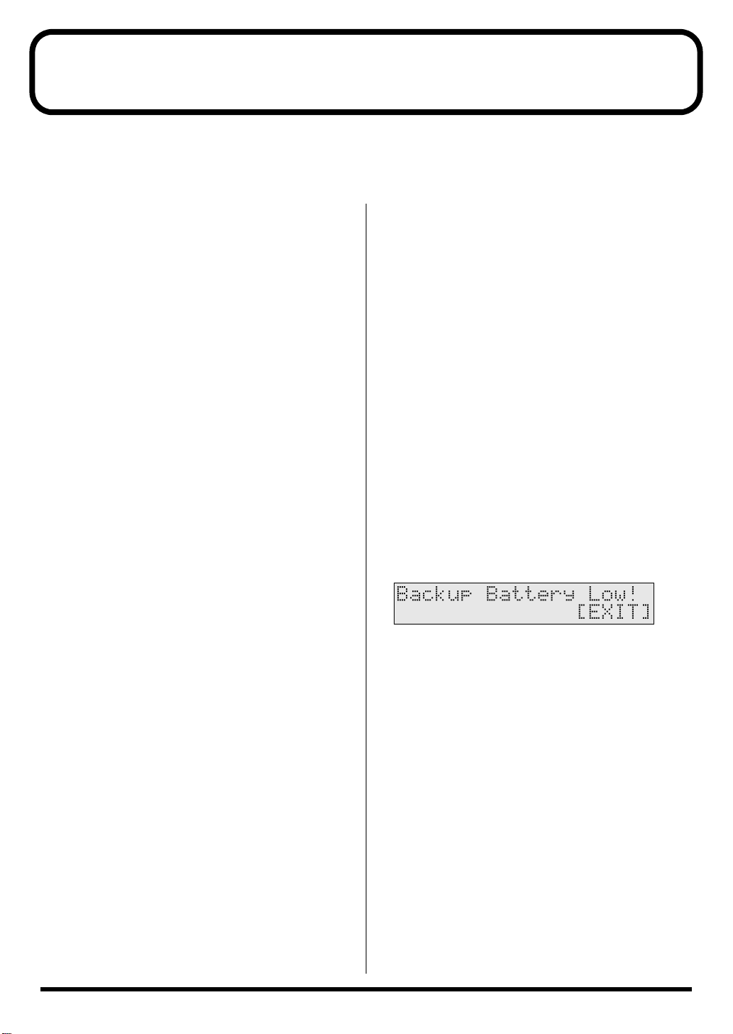
501b
• This unit contains a battery which powers the unit’s
memory circuits while the main power is off. When this
battery becomes weak, the message shown below will
appear in the display. Once you see this message, have
the battery replaced with a fresh one as soon as possible
to avoid the loss of all data in memory. To have the
battery replaced, consult with your retailer, the nearest
Roland Service Center, or an authorized Roland
distributor, as listed on the “Information” page.
Maintenance
401a
• For everyday cleaning wipe the unit with a soft, dry
cloth or one that has been slightly dampened with
water. To remove stubborn dirt, use a cloth impregnated with a mild, non-abrasive detergent. Afterwards,
be sure to wipe the unit thoroughly with a soft, dry
cloth.
402
• Never use benzine, thinners, alcohol or solvents of any
kind, to avoid the possibility of discoloration and/or
deformation.
4
Page 5

Additional Precautions
551
• Please be aware that the contents of memory can be
irretrievably lost as a result of a malfunction, or the
improper operation of the unit. To protect yourself
against the risk of loosing important data, we
recommend that you periodically save a backup copy
of important data you have stored in the unit’s memory
in another MIDI device (e.g., a sequencer).
552
• Unfortunately, it may be impossible to restore the
contents of data that was stored in the unit’s memory or
another MIDI device (e.g., a sequencer) once it has been
lost. Roland Corporation assumes no liability
concerning such loss of data.
553
• Use a reasonable amount of care when using the unit’s
buttons, sliders, or other controls; and when using its
jacks and connectors. Rough handling can lead to
malfunctions.
554
• Never strike or apply strong pressure to the display.
556
• When connecting / disconnecting all cables, grasp the
connector itself—never pull on the cable. This way you
will avoid causing shorts, or damage to the cable’s
internal elements.
558a
• To avoid disturbing your neighbors, try to keep the
unit’s volume at reasonable levels. You may prefer to
use headphones, so you do not need to be concerned
about those around you (especially when it is late at
night).
558c
• Since sound vibrations can be transmitted through
floors and walls to a greater degree than expected, take
care not to allow such sound to become a nuisance to
neighbors, especially at night and when using
headphones. Although the drum pads and pedals are
designed so there is a minimal amount of extraneous
sound produced when they’re struck, rubber heads
tend to produce louder sounds compared to mesh
heads. You can effectively reduce much of the
unwanted sound from the pads by switching to mesh
heads.
559a
• When you need to transport the unit, package it in the
box (including padding) that it came in, if possible.
Otherwise, you will need to use equivalent packaging
materials.
562
• Use a cable from Roland to make the connection. If
using some other make of connection cable, please note
the following precautions.
• Some connection cables contain resistors. Do not use
cables that incorporate resistors for connecting to
this unit. The use of such cables can cause the sound
level to be extremely low, or impossible to hear. For
information on cable specifications, contact the
manufacturer of the cable.
IMPORTANT NOTES
5
Page 6

Contents
USING THE UNIT SAFELY ........................................................................2
IMPORTANT NOTES..................................................................................4
Contents.....................................................................................................6
Features ...................................................................................................12
How to Use This Manual.........................................................................14
Composition of This Manual..................................................................................................14
Terms Used in This Manual ..................................................................................................14
Setup Guide ...................................................15
Panel Descriptions..................................................................................16
Front Panel............................................................................................................................16
Rear Panel ............................................................................................................................18
Making the Settings.................................................................................19
Mounting the TD-6 to the Stand ............................................................................................19
Connecting the Pads and the Pedals....................................................................................20
About Polarity Switch...........................................................................................................21
Connecting Two Pads to Trigger Inputs 5/6 (TOM2/AUX) and 7/8 (TOM3/4)........21
Connecting Two Kick Trigger Units...................................................................................22
Connecting Headphones, Audio Equipment, Amps, and Other Gear ...................................23
Turning On/Off the Power.......................................................................24
Turning Off the Power ...........................................................................................................25
Restoring the Factory Settings (Factory Reset)...................................26
Listening to the Demo Songs.................................................................28
Selecting the Pad Type...........................................................................30
Adjusting the Sensitivity of the Pad......................................................32
About the Pads........................................................................................34
Trigger Inputs and the Pads You Can Use............................................................................34
Trigger Input Functions........................................................................................................ 34
Combinations of Pad and Trigger Type.............................................................................35
Recommended Parameters for the Pads ............................................................................ 36
Playing the Pads ...................................................................................................................37
Pad Head Shots and Rim Shots...........................................................................................37
Cross Stick...............................................................................................................................37
Cymbal Bow Shots/Edge Shots/Bell Shots....................................................................... 38
Cymbal Choke........................................................................................................................39
Hi-Hat Control Pedal .............................................................................................................39
6
Page 7

Contents
Quick Start.....................................................41
Choosing a Drum Kit...............................................................................42
Playing While Listening to the Metronome/Click .................................43
Switching the Click On and Off..............................................................................................43
Adjusting the Click Volume (Level)........................................................................................44
Adjusting the Click Tempo.....................................................................................................45
Playing Along with Songs ......................................................................46
Choosing a Song and Playing Back......................................................................................46
Choosing a Song .................................................................................................................... 46
Playing Back a Song .............................................................................................................. 47
Adjusting the Song Volume...................................................................................................48
Setting the Backing Part (Melodic Instruments etc.) Volume.........................................48
Setting the Drums and Percussion Volume.......................................................................48
Temporarily Changing the Tempo of a Song ........................................................................49
Muting the Pre-programmed Drums in Songs.......................................................................50
Using the Pads to Play Songs................................................................52
Playing with a CD, Tape, or MD (Using MIX IN Jack) ...........................53
Using the TD-6 As a General MIDI Sound Module................................54
Advanced Use................................................55
Chapter 1 Creating Your Own Drum Kit..................(Kit Edit) ..............56
About Drum Kits and the Drum Kit Screen............................................................................56
About the Drum Kits.............................................................................................................56
About the Drum Kit Screen.................................................................................................. 57
Choosing a Drum Kit ....................................................................(Drum Kit)........................57
Choosing the Pad to Edit.......................................................................................................57
Choosing a Pad by Hitting It ...............................................................................................57
Choosing on the TD-6 ...........................................................................................................58
Notation Used in the Screen .................................................................................................58
Helpful Functions for Edit ......................................................................................................58
Listening the INST (Instrument) assigned to a Pad ...........(Preview) ............................ 58
Locking the Setting Screen While Editing One Instrument
Choosing an Instrument ........................................................................................................59
About the Instruments..........................................................................................................59
Choosing from the Group Names.........................................(Inst Group) .......................59
Choosing an Instrument.........................................................(Inst)....................................60
Instrument Settings ......................................................................(INST)..............................60
Adjusting the Volume of the Pad..........................................(Level)................................. 61
Setting the Pan Position..........................................................(Pan).................................... 61
Adjusting the Pitch..................................................................(Pitch).................................. 61
Adjusting the Decay (Length of Sound)...............................(Decay)................................ 61
...(Note Chase) ...................... 59
7
Page 8

Contents
Ambience Settings .......................................................................(AMBIENCE)...................62
Switching Ambience On/Off.................................................(Ambience Switch)............62
Ambience “Send” Level for Each Instrument .....................(Ambience Send Level) .... 62
Choose “Location” Where the Drums are Played ..............(Studio Type).....................62
Changing the Wall Surface Material.....................................(Wall Type) ........................63
Determine the Room Size.......................................................(Room Size)........................ 63
Adjusting the Entire Drum Kit’s Overall Ambience ..........(Ambience Level).............. 63
Equalizer Settings ........................................................................(EQUALIZER)..................64
Switching the Equalizer On/Off
Adjusting the Sound ...............................................................(High Gain, Low Gain).....64
Settings for Various Functions .....................................................(CONTROL) ....................64
Playing a Song by Hitting a Pad............................................(Pad Pattern)...................... 65
Control the “Level” of the Pattern with Playing Dynamics
Pitch Control
with the Hi-Hat Control Pedal On/Off for Each Pad ........(Pitch Control Assign)......66
MIDI Note Number for Each Pad .........................................(Note Number).................. 66
MIDI Gate Time for Each Pad................................................(Gate Time) ........................ 67
Overall Drum Kit Settings.............................................................(COMMON) .....................68
Overall Drum Kit Volume .....................................................(Master Volume) ...............68
Adjusting the Volume of the Pedal Hi-Hat Sound.............(Pedal Hi-Hat Volume)....68
Setting the Range for the Pitch Control
with the Hi-Hat Control Pedal
Naming the Drum Kit.............................................................(Kit Name)..........................69
Copying a Drum Kit ......................................................................(COPY)............................69
Restoring the Factory Settings for the Edited Drum Kit..................................................70
Switching the Order of the Drum Kits...........................................(EXCHANGE)..................70
............................................. (Master Equalizer Switch)
...(Pad Pattern Velocity) ......65
...................................................... (Pedal Pitch Control Range)
..64
...68
Chapter 2 Making the Pad and Trigger Settings.....(SETUP/TRIG) .....71
About the Screen Display......................................................................................................71
Notation Used in the Screen.................................................................................................71
About the Input Indicator ....................................................................................................71
Selecting the Pad Type............................................................(Trigger Type).................... 71
Setting the Pad Sensitivity and Making Other Settings................(TRIGGER BASIC)..........72
Adjusting the Pad Sensitivity ................................................(Sensitivity)........................ 73
Setting the Minimum Levels for the Pads............................(Threshold)......................... 73
Adjust How Playing Dynamics Changes the Volume.......(Trigger Curve).................. 73
Eliminate Crosstalk Between Pads........................................(Crosstalk Cancel)............. 74
Fine-Tuning the Trigger Parameter Settings
Adjusting the Trigger Signal Detection Time......................(Scan Time) ........................75
Detecting Trigger Signal Attenuation
and Cancelling Incorrect Triggering.....................................(Retrigger Cancel) .............75
Double Triggering Prevention...............................................(Mask Time).......................75
Setting Rim Sensitivity on the PD-120 and PD-80R............(Rim Sens) ..........................76
Using the TD-6 with Acoustic Triggers..................................................................................76
.................................(TRIGGER ADVANCED)
..74
Chapter 3 Global Settings for the TD-6 ...................(SETUP/UTILITY,
Factory Reset) ...77
Making the Global Settings ..........................................................(UTILITY).........................77
Display Contrast Adjustment................................................(LCD Contrast) .................. 77
Percussion Part Volume Control...........................................(Percussion Part Level).....77
8
Page 9

Contents
Backing Instruments Volume Control..................................(Backing Level).................. 78
Muting Parts of a Song............................................................(Mute) .................................78
Tuning the TD-6.......................................................................(Master Tune) ....................78
Preview Volume Control........................................................(Preview Velocity) ............79
Checking the Remaining Amount of Memory....................(Available Memory) .........79
Restoring the Factory Settings.....................................................(Factory Reset)................79
Chapter 4 Setting the Metronome............................(Click Edit)...........80
Switching the Click On/Off............................................................(Click) ..............................80
Tempo Adjustment .......................................................................(Tempo)...........................80
Setting the Way the Click Sounds.........................................................................................80
Volume Adjustment................................................................(Click Level).......................80
Setting the Time Signature.....................................................(Time Signature)................ 81
Setting the Interval ..................................................................(Interval).............................81
Selecting the Click Sound.......................................................(Inst).................................... 81
Stereo Position..........................................................................(Pan)....................................81
Inserting a Count Before Playback or Recording
...................(Play Count In, Rec Count In)
..81
Chapter 5 Editing Songs...........................................(SONG Edit).........82
About Songs and the Song Screen.......................................................................................82
About Songs ........................................................................................................................... 82
About the Song Screen..........................................................................................................83
Choosing a Song...................................................................................................................84
Choosing from a Category .....................................................(Song Category).................84
Choosing a Song ......................................................................(Song)..................................84
Playing Back a Song .............................................................................................................84
Convenient Function for Playback...................................................................................... 84
Adjusting the Song Volume...................................................................................................85
Muting a Selected Part.................................................................(Part Mute) ......................85
Overall Song Settings...................................................................(COMMON) .....................86
Setting the Tempo....................................................................(Tempo) .............................. 86
Selecting How the Song Plays Back (LOOP, 1SHOT, TAP)
Playing Back the Song from the First Note/Event .............(Quick Play).......................87
Reset Time When Using Tap Playback.................................(Reset Time) ....................... 87
Preventing Layering of Sounds in Tap Playback................(Tap Exclusive Switch)..... 87
Protecting User Song Settings................................................(Song Lock) ........................ 87
Naming a Song.........................................................................(Song Name)......................88
Part Settings.................................................................................(PART) ............................88
Choosing Percussion Set and Instruments ..........................(Percussion Set, Inst).........89
Adjusting the Part Volume.....................................................(Level).................................89
Adjusting the Stereo Position.................................................(Pan).................................... 90
Adjusting the Amount of Ambience.....................................(Ambience Send Level) ....90
Adjusting the Bend Range......................................................(Bend Range) .....................90
Copying a Song............................................................................(COPY)............................90
Deleting a Song............................................................................(DELETE)........................91
Erasing Performance Data in a Song...........................................(ERASE)..........................92
...(Play Type)......................... 86
9
Page 10

Contents
Chapter 6 Recording a Song
Preparations for Recording ...................................................................................................93
When Recording Pad Performances...................................................................................93
Recording Performances by External MIDI Devices........................................................93
How To Record
Setting the Time Signature.....................................................(Time Signature)................ 94
Setting the Number of Measures...........................................(Length) ..............................94
Setting the Song Tempo..........................................................(Tempo) ..............................94
Quantize During Recording...................................................(Quantize) ..........................95
Selecting the Recording Method
(Loop All, Loop1, Loop2, Replace)........................................(Recording Mode) .............95
Start Recording with a Pad or Pedal Trigger.......................(Hit Pad Start)....................95
....................................................................................(RECORDING STANDBY)
.............................................. (Realtime Recording)
Chapter 7 Making the MIDI Settings ........................(SETUP/MIDI,
BULK DUMP) .....96
About MIDI ............................................................................................................................96
MIDI Connectors ................................................................................................................... 96
MIDI Channels and Multi-timbral Sound Modules......................................................... 96
How the Internal Sequencer Operates................................................................................97
Making the MIDI Settings .............................................................(MIDI COMMON).............97
Automatically Switching Instrument Settings Screens......(Note Chase)......................98
When Using as MIDI Controller
for External MIDI Device Only..............................................(Local Control)...................98
Synchronizing with an External MIDI Device ....................(Sync Mode).......................98
Setting Priority for Playing Drums and Percussion ...........(Channel 10 Priority)........99
Hi-Hat Control Pedal Data Reduction..................................(Pedal Data Thin) .............. 99
Switch to the GM (General MIDI) Mode..............................(GM Mode) ......................100
Preventing the TD-6 from Switching
to GM (General MIDI) Mode .................................................(Rx GM ON).....................100
Mixing MIDI Signals Coming to the MIDI IN
with Real Time Performance on the Pads............................(Soft Thru)........................ 101
Set the Device ID......................................................................(Device ID).......................101
Setting the TD-6 So That Program Changes
Are Not Transmitted ..................................................(Tx PC Sw) .......................102
Are Not Received........................................................(Rx PC Sw) ....................... 102
MIDI Channel Settings for a Part..................................................(MIDI PART)..................102
MIDI Messages Stop Function for Specific Parts
in GM (General MIDI) Mode.........................................................(GM PART)....................103
Saving Data to an External MIDI Device......................................(BULK DUMP)...............103
Returning Saved Data to the TD-6....................................................................................104
..93
..94
Chapter 8 Features Using MIDI and Setting Examples......................105
About Transmitting/Receiving Program Changes ...............................................................105
Triggering an External Sound Device by Playing the TD-6.................................................105
Combining with an External MIDI Sequencer......................................................................106
Importing Sequence Data from an External MIDI Device
to the TD-6’s Internal Sequencer .......................................................................................106
Recording Your Performance to an External Sequencer................................................106
Using the TD-6 As a Sound Module....................................................................................107
10
Page 11

Contents
Appendices .................................................. 109
Troubleshooting....................................................................................110
No Sound ............................................................................................................................110
No Sound/Low volume from Device Connected to the MIX IN Jack ...................................112
Drum Kit Does Not Sound As Intended...............................................................................112
Pad Does Not Sound As Intended ......................................................................................113
Song Does Not Sound As Intended ....................................................................................114
Sound is distorted................................................................................................................114
Problems Operating the TD-6 .............................................................................................115
Display Is Too Light Or Too Dark........................................................................................115
Messages and Error Messages............................................................116
System and Battery Error Messages...................................................................................116
Messages and Error Messages Related to Sequencers and Songs...................................116
Messages and Error Messages Related to MIDI.................................................................117
Drum Kit List..........................................................................................118
Drum Instrument List............................................................................120
Preset Percussion Set List...................................................................124
Backing Instrument List........................................................................126
Preset Song List....................................................................................128
Parameter List .......................................................................................130
MIDI Implementation .............................................................................135
Block Diagram .......................................................................................151
Specifications........................................................................................152
Index.......................................................................................................153
11
Page 12

Features
Full Palette of Internal Sounds for All Uses,
from Practice to Live Performance
■ Includes 99 Different Drum Kits
You can immediately start playing any of a variety of drum kits, just by selecting the drum kit.
Whether for practice or live performances, these kits can be applied in a wide range of situations.
■ 1, 042 Drum Instruments
You can combine different drum instruments used in a wide range of musical genres to create your
own original drum kits.
■ 150 Different Preset Songs
To get right down to practicing, you merely need to select a Preset song. Then you can play the
drum part just by muting only the Preset song’s drum performance.
You also get 100 internal songs that you can use to record your own drum performances (User
songs).
■ 262 Backing Instruments
The TD-6’s abundance of backing instruments allow you to record in a variety of musical genres.
Rich Expression
■ Cross Stick Technique Available (p. 37)
■ Play Rim Shots (p. 37), Cymbal Edge Shots (p. 38),
and Use Cymbal Choking (p. 39)
■ Pitch Control Available with the Hi-Hat Control Pedal (p. 66)
You can use the hi-hat control pedal to change the pitch of the pad instruments.
12
Page 13
Function and Operations Perfect for Live
Performances
■ Flat Top Design for Great Visibility
■ Buttons Light for Easy Operation, Even On Stage
■ Large [INC/+] and [DEC/-] Buttons That Can Be Operated Even
with Drum Sticks
Convenient Functions for Practicing
■ Includes Metronome (Click) (p. 80)
■ Includes Part Mute Function for Muting of Specific Parts
When Playing With Preset Songs (p. 50, p. 78)
Features
Expandability/Compatibility
■ Also Compatible With
Pads (PD-5, PD-6, PD-7, PD-9, PD-80, PD-80R, PD-100, PD-120)
Cymbals (CY-6, CY-12H, CY-14C, CY-15R)
Kick Trigger Units (KD-5, KD-7, KD-80, KD-120)
Hi-Hat Control Pedals (FD-7, FD-6; FD-6 is included with TD-6K)
■ Use the TD-6 As a MIDI Sound Module With an External
Sequencer (p. 106)
■ Support for General MIDI (p. 54, p. 100)
The TD-6 has a GM mode that can play back GM scores.
This mode includes a function allowing you to mute the sound only of a specified part during
playback of GM scores. This is a very convenient feature for practicing and playing along.
General MIDI ( ) System
General MIDI is a set of recommendations which seeks to provide a way to go beyond the
limitations of proprietary designs, and standardize the MIDI capabilities of sound
generating devices. Sound generating devices and music files that meet the General MIDI
standard bear the General MIDI logo ( ).
Music files bearing the General MIDI logo can be played back using any General MIDI
sound generating unit to produce essentially the same musical performance.
13
Page 14
How to Use This Manual
Composition of This Manual
This owner’s manual is organized as follows.
Setup Guide (p. 15)
For those using the TD-6 for the first time, this volume explains the
preparations needed for playing sounds, including how to set up
the stand, make pad settings, and turn on the TD-6’s power.
Also provided are explanations of how to combine the TD-6
with other optional pads for fullest utilization of the TD-6’s
features and functions.
Quick Start (p. 41)
This contains descriptions explaining how to easily enjoy
performing with the TD-6’s numerous internal drum kits and
Preset songs.
Advanced Use (p. 55)
The TD-6 allows you use the drum kits you like to create new drum
kits and to create songs from recordings of what you play.
This section provides detailed explanations of all of the TD-6’s
functions.
• Chapter 1 Functions For Creating Drum Kits (p. 56)
Here are the settings used for creating sounds.
• Chapter 2 Functions For Correctly Performing with
the Pads (p. 71)
This describes the settings you need to make in order to
get the most expression from the TD-6 and pads.
• Chapter 3 TD-6 Settings (p. 77)
Included in this section are settings such as display
contrast and song volume that are applied to the TD-6
as a whole.
• Chapters 4–6 Using the sequencer and related
functions (p. 80)
Found here are metronome (click) settings, as well as
song performance, recording, editing, and other settings
for sequencers.
• Chapters 7–8 MIDI Settings and Examples of How
MIDI Is Used (p. 96)
This chapter explains how to use MIDI —whether it be
for saving data to an external device, or for using the
TD-6 as a General MIDI sound module.
Terms Used in This Manual
• Button names are enclosed in square brackets “[ ],” as in
[KIT] button.
• (p. **) indicates a reference page.
• Steps in operations may be abbreviated as described
below.
[KIT] ➝ [EDIT]
1. Press [KIT].
2. Press [EDIT].
[SHIFT] + [KIT]
1. While holding down [SHIFT], press [KIT].
• The functions of some buttons, such as [EDIT (SETUP)],
change if pressed while [SHIFT] is held down; the
function that is enabled when [SHIFT] is held down is
shown in parentheses.
• Symbols appearing before the beginning of sentences in
the manual have the following meanings.
These indicate cautionary notes. Be sure to read
them.
These are memos containing information
regarding settings and functions. Read it as
necessary.
These are useful hints for operation. Read it as
necessary.
These point to reference information. Read it as
necessary.
These are descriptions of terminology. Read it as
necessary.
* The explanations in this manual include illustrations that depict
what should typically be shown by the display. Note, however, that
your unit may incorporate a newer, enhanced version of the system
(e.g., includes newer sounds), so what you actually see in the
display may not always match what appears in the manual.
Appendices (p. 109)
If you run into problems, refer to “Troubleshooting” to make sure
that the settings are correct. If an error message appears during
operation, refer to “Messages and Error Messages” and take
appropriate action. This section also provides various lists, and the
MIDI implementation charts.
14
Page 15

Setup Guide
Setup Guide
15
Page 16
Panel Descriptions
Front Panel
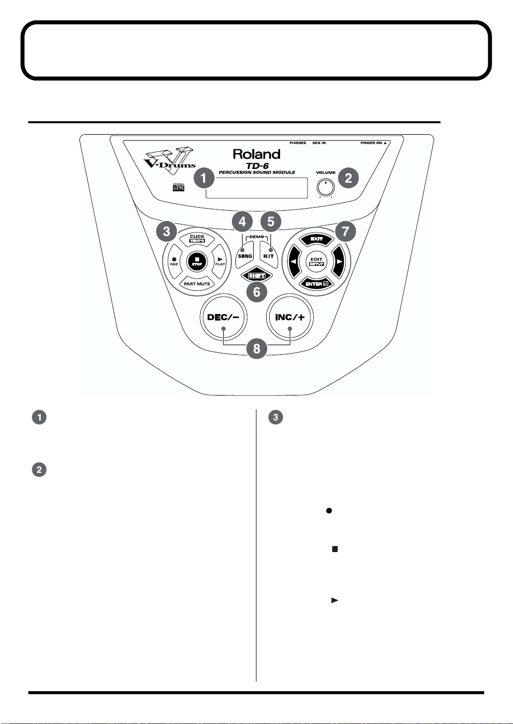
fig.P-022
Display
The screen displays information, indicating the
drum kit name, song name, and settings etc.
VOLUME Knob
Adjusts the volume of the TD-6 (p. 25). Even
when headphones are connected, sound will still
be output from the various output jacks.
16
Sequencer Section
• CLICK (TEMPO) Button
Turn the click on/off (p. 43).
When you hold down the [SHIFT] button and
press the [CLICK (TEMPO)] button, the
tempo settings screen appears in the display
(p. 45, p. 49).
• REC Button
Calls up the recording settings screen
(Recording Standby; p. 94).
• STOP Button
Stop song playback (p. 47). When pressed
while the song is stopped, this returns you to
the beginning of the song.
• PLAY Button
Play back the song (p. 47). Starts recording if
pressed when the TD-6 is in recording
standby mode (p. 94).
• PART MUTE Button
Mutes the performance of specified parts (p.
50).
Page 17

Panel Descriptions
SONG Button
Calls up the song’s basic settings screen (p. 83).
KIT Button
Calls up the drum kit’s basic settings screen (p.
57).
SHIFT Button
Used in conjunction with other buttons.
Operation Function
[SHIFT] + [KIT] Gives a preview of the sound
of the instrument assigned to
the selected pad (Preview; p.
58)
[SHIFT] +
[ ], [ ]
[SHIFT] +
[CLICK (TEMPO)]
[SHIFT] +
[EDIT (SETUP)]
[SHIFT] + [SONG] Displays the volume settings
[SHIFT] +
[PLAY ]
[SHIFT] +
[STOP ]
[SHIFT] +
[PART MUTE]
[SHIFT] +
[INC/+], [DEC/-]
• Selects the trigger input
(Trigger Select; p. 58)
• Deletes or inserts one
character when setting
drum kit names and song
names (p. 69, p. 88)
Displays the tempo settings
screen (p. 45, p. 49)
For making overall settings for
the TD-6 (Setup; p. 71, p. 77, p.
93)
screen for the backing
instruments (melodic and
other instruments) (p. 48)
While the song is playing
back, the buttons
corresponding to the
percussion pad drum tones
are lit (p. 47).
Jumps to songs that have not
been used (new User songs)
(p. 93)
Displays the settings screen
for muting parts (p. 78)
• For making large changes
at a time in the values of
settings
• Changes instrument groups
and song categories (p. 59,
p. 84)
• Switches uppercase and
lowercase letters and
symbols when setting
drum kit names and song
names (p. 69, p. 88)
Editing section
• EXIT Button
Returns to the previous stage screen. When
pressed a number of times, the display returns
to either the Drum Kit screen or the Song
screen.
•, Button
These switch the screen if pressed when “ ”
or “ ” is shown in the display.
You can select the trigger input by holding
down the [SHIFT] button and pressing [ ]
or [ ] (p. 58).
In the SONG screen, rewinding and fast
forwarding are carried out in one-measure
units (p. 47).
• EDIT (SETUP) Button
Displays the drum kit or song settings screen.
By holding down the [SHIFT] button and
pressing the [EDIT (SETUP)] button, you can
make overall settings for the TD-6.
• ENTER Button
Switches the screen if pressed when “ ” is
shown in the display.
INC/+ (Increment) Button,
DEC/- (Decrement) Button
These are used to switch drum kits and songs
and to make changes in the settings values.
• Pressing the [INC/+] button increases the
value, and pressing the [DEC/-] button
decreases the value.
• When making an on/off setting, [INC/+] will
turn the setting on and [DEC/-] will turn it
off.
• When [SHIFT] is held down and [INC/+] or
[DEC/-] is pressed, settings values are then
changed in larger increments or decrements.
• When [INC/+] is held down and then [DEC/-]
is pressed, settings values increase rapidly;
when [DEC/+] is held down and then [INC/-]
is pressed, settings values then decrease
rapidly.
Setup Guide
17
Page 18
Panel Descriptions
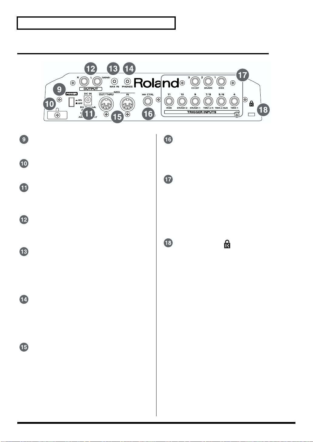
Rear Panel
fig.P-023
POWER Switch
Switch turns the power on/off (p. 24).
Cord Hook
Anchor the power cord (p. 23).
AC Adaptor Jack
Connect the supplied AC adaptor to this jack (p.
23).
OUTPUT Jacks (L (MONO), R)
Connect these to your amp or audio system. For
monaural output use the L/MONO jack (p. 23).
MIX IN Jack
Connect this to your CD, MD, cassette player, or
other similar device (p. 53).
The sound that is input to this jack will be output
from the OUTPUT jacks and the PHONES jack.
PHONES Jack
A pair of stereo headphones can be connected to
this jack (p. 23).
Even when headphones are connected, sound
will still be output from the output jacks.
HH CTRL (Hi-Hat Control) Jack
Connect a hi-hat control pedal (the optional FD7 or FD-6; FD-6 is included with the TD-6K) here.
(p. 20)
TRIGGER INPUTS
Use these inputs to connect optional pads,
cymbals, and kick trigger units to the TD-6 (p.
20).
For more detailed information on each trigger
input, refer to “Trigger Inputs and the Pads You
Can Use” (p. 34).
Security Slot ( )
http://www.kensington.com/
MIDI Connectors (IN, OUT/THRU)
Use these connectors when using a MIDI
sequencer, MIDI keyboard, or other MIDI device
to play sounds with the TD-6, when using the
TD-6 and pads to play sounds from an external
MIDI sound generator, or when saving the TD6’s settings to, or loading settings from a MIDI
sequencer.
18
Page 19
Set p G ide
Making the Settings
Mounting the TD-6 to the Stand
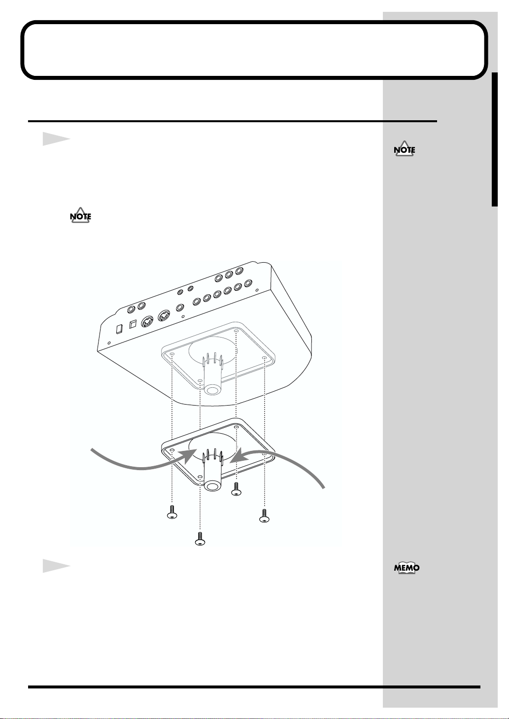
1
Attach the stand holder (included with the optional drum stand) to the
TD-6.
Using the screws attached to the bottom panel, attach the holder so the unit
is oriented as shown in the diagram.
Use the 8 mm screws (M5 x 8) provided with the TD-6. Use of other screws
may result in damage to the unit.
fig.P-009.e
• When turning the unit
upside-down, get a
bunch of newspapers or
magazines, and place
them under the four
corners or at both ends
to prevent damage to
the buttons and controls.
Also, you should try to
orient the unit so no
buttons or controls get
damaged.
• When turning the unit
upside-down, handle
with care to avoid
dropping it, or allowing
it to fall or tip over.
Narrow
2
Attach the TD-6 and stand holder to the drum stand (such as the
optional MDS-6, MDS-7U, MDS-8, or MDS-10).
For details on assembling the drum stand and attaching the TD-6, refer to the
owner’s manual for the drum stand.
Wide
To attach the TD-6 to a
cymbal stand or other such
stand, you may want to
use the optional APC-33
All Purpose Clamp to
secure the stand holder. It
can be attached to a pipe of
10.5 mm–30 mm radius.
19
Page 20
Making the Settings
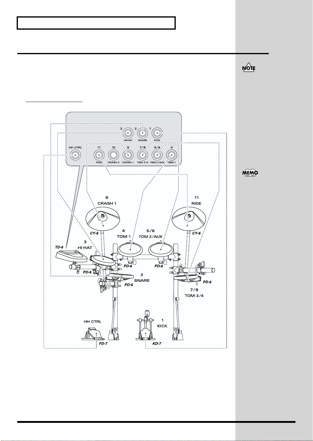
Connecting the Pads and the Pedals
Using the provided cables, connect the pads, cymbal pads, hi-hat control
pedal, and kick trigger unit.
Carefully refer to the numbers shown in the illustration and connect to the
appropriate TRIGGER INPUT jacks on the TD-6's rear panel.
Setting Example
fig.P-011.e
TRIGGER INPUT jacks
Before using pads with
mesh heads (PD-80, PD80R, PD-100, PD-120, KD80, or KD-120), be sure to
adjust the head tension.
Striking the head when the
head tension is loose may
damage the sensor. For
more information on
adjusting the head tension,
refer to the owner’s
manual for each pad.
For fullest performance
expression, make exclusive
use of Roland’s line of
optional pads (PD-5, PD-6,
PD-7, PD-9, PD-80, PD80R, PD-100, and PD-120),
cymbals (CY-6, CY-12H,
CY-14C, and CY-15R), and
kick trigger units (KD-7,
KD-80, and KD-120).
20
Page 21

■ About Polarity Switch
If you are using the PD-7, PD-9, or KD-7, move the pad’s polarity switch to
the “- (Roland)” position. For more detailed information regarding the
polarity switch, refer to your PD-7, PD-9, or KD-7 owner’s manual.
fig.P-011a.e
POLARITY
+
- (Roland)
■ Connecting Two Pads to Trigger Inputs
5/6 (TOM2/AUX) and 7/8 (TOM3/4)
Making the Settings
Setup Guide
With the optional cable (PCS-31) or standard insert cable, two pads may be
connected to the trigger inputs 5/6 (TOM2/AUX) and 7/8 (TOM3/4).
fig.P-012.e
TD-6 Rear Panel
These trigger inputs do not
handle rim sounds.
PD-6
21
Page 22
Making the Settings
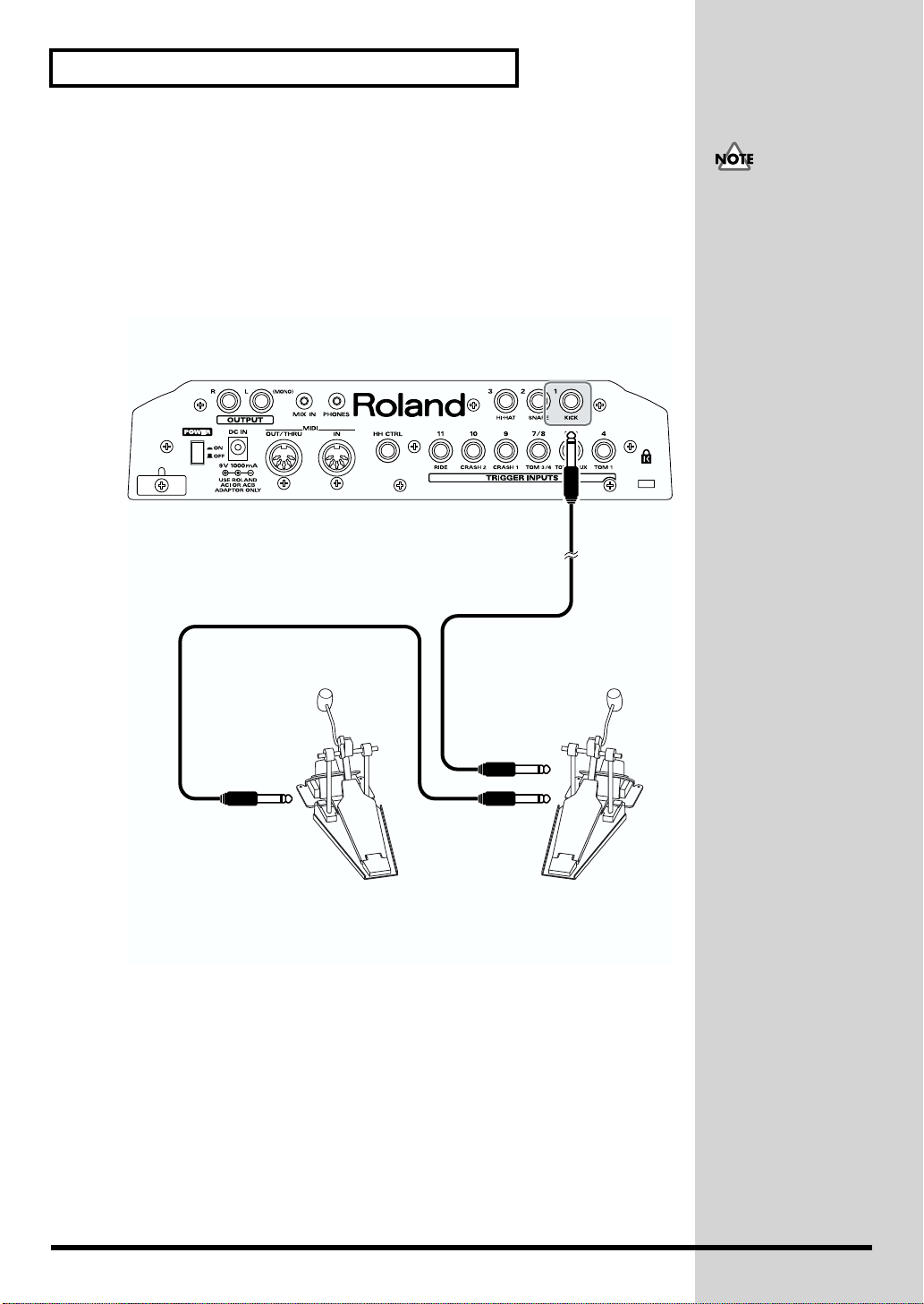
■ Connecting Two Kick Trigger Units
When using the KD-7 kick trigger unit (optional), you can connect two KD-7s
together for twin pedal performances.
When connecting two KD-7s with the KD-7’s Mix In jack, the Kick Trigger
signal is slightly weakened. In this case, raise the sensitivity for the trigger
inputs to which the KD-7’s are connected (SETUP/TRIG BASIC/Sensitivity;
p. 73).
fig.P-013.e
TD-6 Rear Panel
When using two KD-7s,
you cannot assign different
instruments to each unit
individually.
Output Jack
Output Jack
Mix In Jack
Kick Trigger Units (KD-7)
+
Kick Pedals
22
Page 23
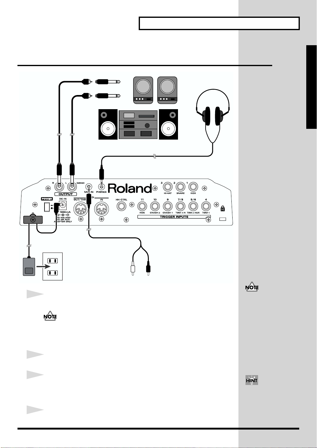
Connecting Headphones, Audio
b
J
Equipment, Amps, and Other Gear
fig.P-010
R
Making the Settings
L
Stereo miniature phone type
Setup Guide
CD/MD deck, cassette player, etc.
1
Turn off the power of all devices before you make connections.
To prevent malfunction and/or damage to speakers or other devices, always
turn down the volume, and turn off the power on all devices before making
any connections.
2
Connect the supplied AC adaptor to the AC adaptor jack.
3
Connect the OUTPUT L(MONO) and R jacks on the rear panel to your
audio system or amp. If using headphones, connect them to the
PHONES jack.
4
Plug the AC adaptor plug into a power outlet.
To prevent the inadvertent
disruption of power to
your unit (should the plug
e pulled out accidentally),
and to avoid applying
undue stress to the AC
adaptor jack, anchor the
power cord using the cord
hook, as shown in the
illustration.
Using the TD-6’s MIX IN
ack, allows you to play
along with a CD or other
such sound input (p. 53).
23
Page 24
Turning On/Off the Power
b
Once the connections have been completed (p. 23), turn on power to your
various devices in the order specified. By turning on devices in the wrong order,
you risk causing malfunction and/or damage to speakers and other devices.
fig.P-001
1, 5 3
5
1
Turn the [VOLUME] knob completely to the left to lower the volume to
the minimum level.
2
Turn down the volume control on the connected amp or audio system.
3
Press the [POWER] button to turn on the power.
Precautions When Turning on the Power
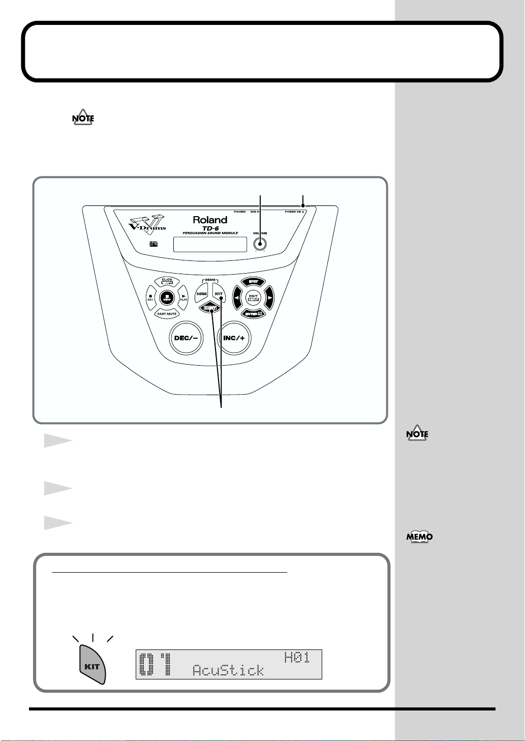
After the power is turned on, the drum kit name (shown in the
following figure) appears in the display; do NOT press any pad
or pedal until [KIT] has lighted.
fig.P-002ai
This unit is equipped with
a protection circuit. A brief
interval (a few seconds)
after power up is required
efore the unit will operate
normally.
If the hi-hat control pedal
(the optional FD-7; or for
the TD-6K exclusively, the
FD-6) is pressed when the
power is turned on, control
of the hi-hat’s opening and
closing will not work
correctly. Striking the pads
when turning on the
power degrades the pad
response when the pads
are struck lightly.
24
Page 25
4
Turn on the power to the connected amp or audio system.
5
Press [SHIFT] + [KIT] or strike the pad, and while listening to the
sound, gradually bring up [VOLUME] to adjust the volume level.
Also raise the volume level of the connected amp or audio system to the
appropriate level.
No Sound Even When Pressing [SHIFT] + [KIT]
Check the following points.
When Using an Amp or Audio System
• Is the amp or audio system volume setting correct?
• Are the TD-6 and the amp or audio system connected correctly?
• Is there a problem with any connector cable?
• Have the input select settings of your audio system or amp been
made correctly?
When using headphones:
• Are the headphones connected to the [PHONES] jack?
Turning On/Off the Power
Caution Concerning
Volume
If the volume levels used
when striking the pads are
left unchanged when
playing back demo songs
or other songs, the volume
may increase suddenly,
which may cause ear pain
and damaged speakers.
Before playing back songs
or patterns, rotate the
[VOLUME] knob
counterclockwise to lower
the volume levels, then
readjust to a suitable
volume while listening to
the playback.
Setup Guide
Turning Off the Power
1
Completely turn down the volume of the TD-6 and any connected
external devices.
2
Turn off the power to all external devices.
3
Press the TD-6’s [POWER] switch to turn off the power.
25
Page 26
Restoring the Factory Settings (Factory Reset)
j
This restores the pad and instrument settings, song data, and other
information stored in the TD-6 to the original factory settings.
fig.P-003
21
All data and settings
stored in the TD-6 are lost
in carrying out this
operation. Use the “Bulk
Dump” operation to save
crucial data and settings to
an external MIDI device
(SETUP/BULK DUMP/
Bulk Dump; p. 103).
4 3, 5, 6
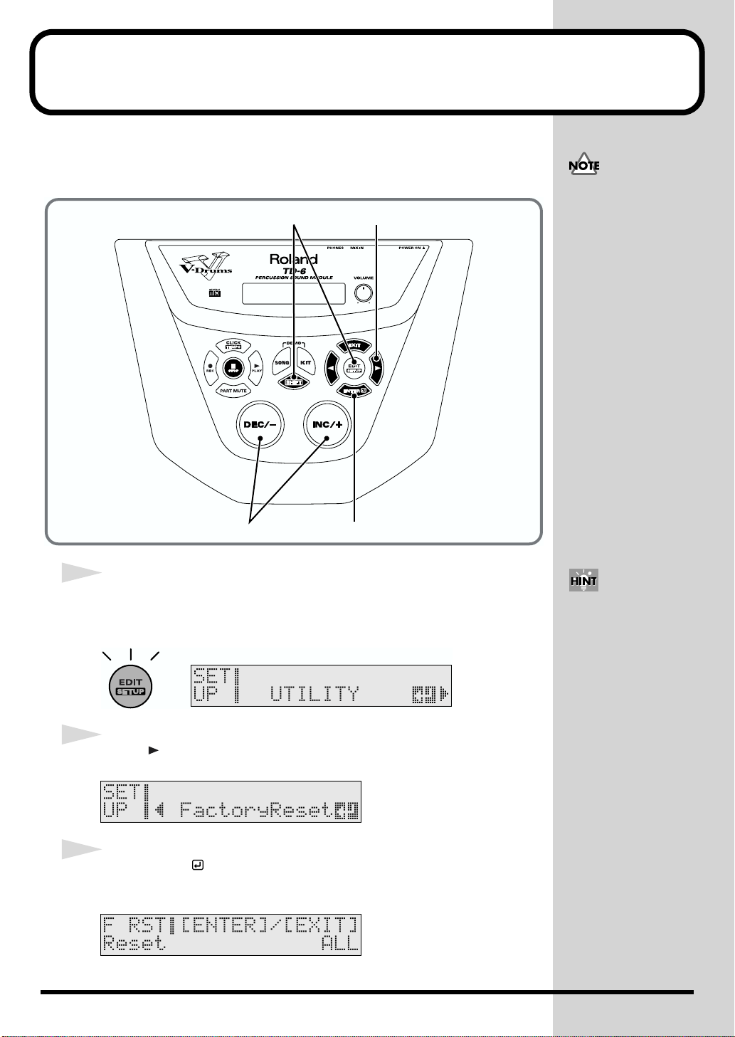
1
While holding down [SHIFT], press [EDIT (SETUP)].
[EDIT (SETUP)] lights.
fig.P-004ai
2
Press [ ] to select “FactoryReset.”
fig.P-005_50
3
Press [ENTER ].
The Factory Reset screen appears.
fig.P-006_50
When [SHIFT] and
[EDIT (SETUP)] are held
down when the power is
turned on, the display
umps to the Factory Reset
screen. When carrying out
Factory Reset, read from
Step 4.
26
Page 27
Restoring the Factory Settings (Factory Reset)
4
Press [INC/+] or [DEC/-] to select the parameter you want to restore to
factory settings.
Here, select “ALL” to restore all of the settings to the original factory
values.
ALL:
All internal settings will be restored to the factory settings.
THIS DRUM KIT:
Only the settings for the currently selected drum kit are restored to
the factory settings.
ALL DRUM KITS:
The settings for all of the TD-6’s internal drum kits are restored to the
factory settings.
ALL SONGS:
All of the TD-6’s internal song data is restored to the factory settings.
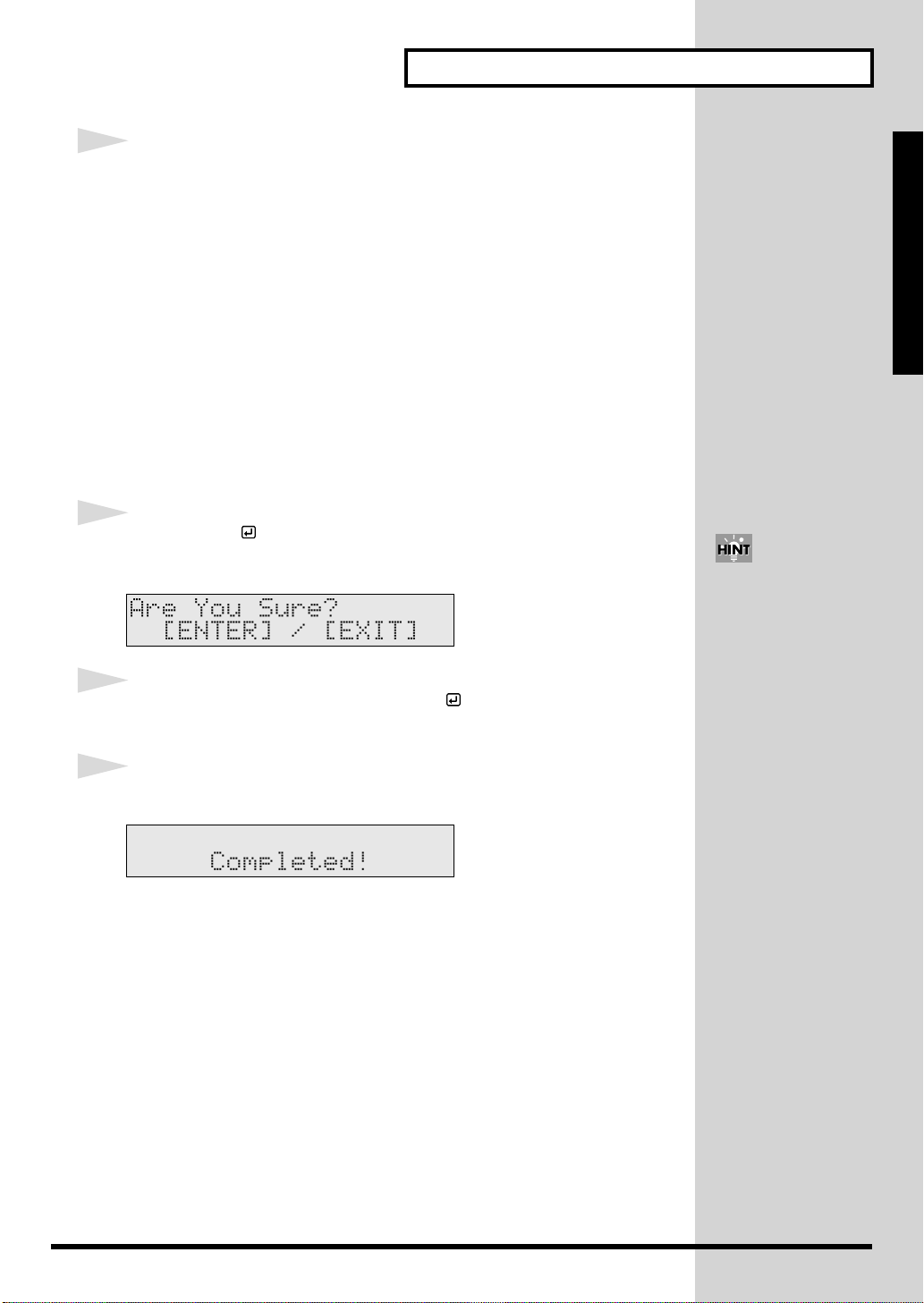
5
Press [ENTER ].
Setup Guide
The confirmation screen appears.
fig.P-007_50
6
If you’re ready to proceed, press [ENTER ], and the Factory Reset
operation will be executed.
7
When the Factory Reset is finished, the Completed screen appears.
fig.P-008_50
Press [EXIT] to cancel the
operation.
27
Page 28
Listening to the Demo Songs
The TD-6 features four demo songs demonstrating the TD-6’s sounds and
expressive capabilities.
The drums played on the demo songs were played in real time into a
sequencer.
fig.P-029
5341
1
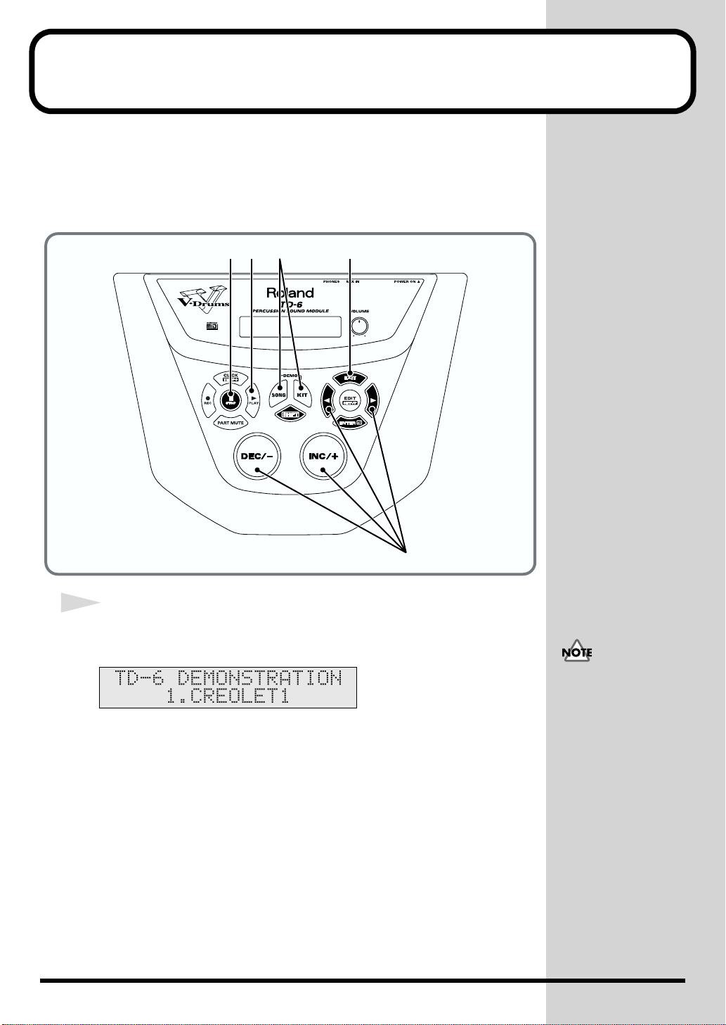
While holding down [KIT], press [SONG].
The “DEMONSTRATION” screen appears.
fig.P-030_50
2
• All rights reserved.
Unauthorized use of this
material for purposes
other than private,
personal enjoyment is a
violation of applicable
laws.
• No data for the music
that is played will be
output from MIDI OUT.
28
Page 29

2
b
b
Press [INC/+] or [DEC/-], or press [ ] or [ ] to select the song to
play back.
1. CREOLET1
Copyright © 2001, Roland Corporation
Drum kit being used: #72 “RoseWood”
Listening to the Demo Songs
Setup Guide
2. CREOLET2
Copyright © 2001, Roland Corporation
Drum kit being used: #20 “Natural”
3. TC R&B
Copyright © 2001, Roland Corporation
Drum kit being used: #1 “AcuStick’
4. SNAG LTN
Copyright © 2001, Roland Corporation
Drum kit being used: #3 “Groove”
3
Press [PLAY ].
Playback of the demo songs begins, and the four demo songs are played
continuously in sequence.
4
When you want to stop the performance, press [STOP ].
5
When you have finished listening to the demo song, press [KIT],
[SONG] or [EXIT].
Caution Concerning
Volume
If the volume levels used
when striking the pads are
left unchanged when
playing back demo songs,
the volume may increase
suddenly, which may
cause ear pain and
damaged speakers. When
playing back demo songs,
rotate [VOLUME] to the
left (counterclockwise) to
ring the volume level
ack down, then while
playing back the song,
readjust the volume to an
appropriate level.
29
Page 30
Selecting the Pad Type
j
Make the settings for the type of pads to be used (trigger type) to ensure that
the TD-6 accurately receives what is being played on the pads.
Set each trigger input as described below.
Settings optimized for the TD-6K are provided in factory settings on the
TD-6.
fig.P-014
8 1
The following parameters
are automatically set to the
most efficient values for
each pad when you select
the trigger type.
Basic Trigger Parameters
(SETUP/TRIG BASIC; p.
72)
• Sensitivity
• Threshold
• TrigCurve
Advanced Trigger
Parameters
(SETUP/TRIG ADVNCD;
p. 74)
• Scan Time
• Retrig Cancel
• Mask Time
• Rim Sens
1
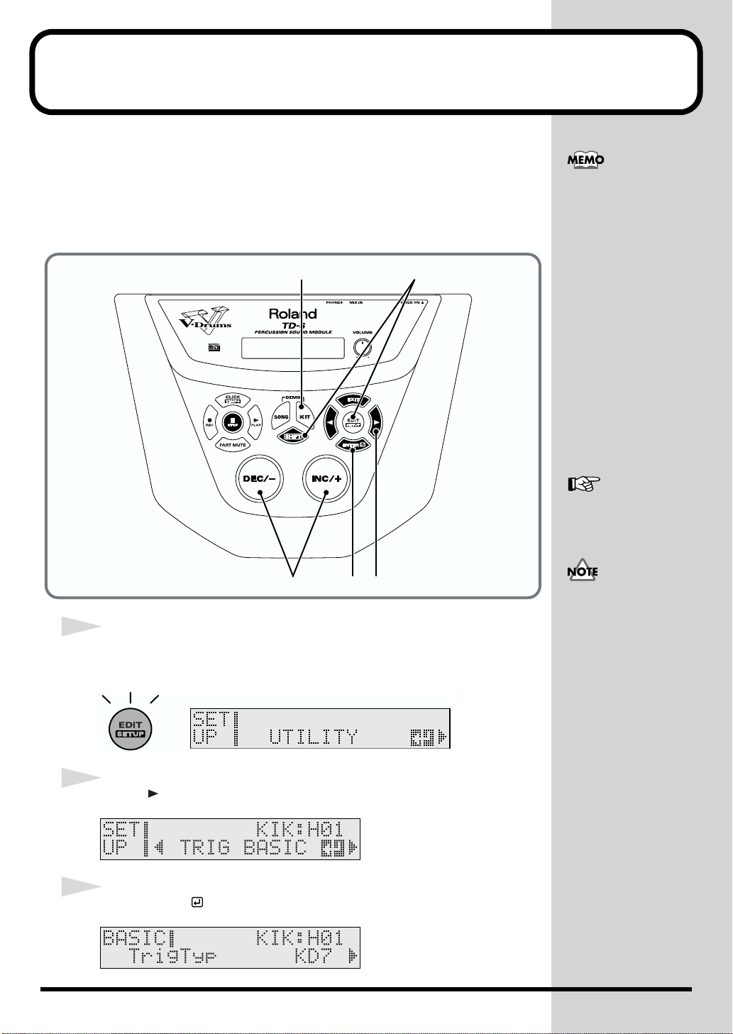
While holding down [SHIFT], press [EDIT (SETUP)].
[EDIT (SETUP)] lights.
fig.P-015ai
2
Press [ ] to select “TRIG BASIC.”
fig.SETUP-BASIC_50 (SETUP-BASIC)
3
Press [ENTER ].
fig.P-016_50
For the most suitable
values for each trigger
type, refer to p. 36.
236
You may need to adjust
the value since these are
ust the reference value.
30
Page 31

4
b
Strike the pad you wish to set.
The setting screen for the struck pad appears.
5
Select the most suitable trigger type from the following chart for the
pad you are using.
Pad Trigger Type Pad Trigger Type
PD-5 PD7/9 CY-6 CY6
PD-6 PD6 CY-12H CY Type
PD-7 PD7/9 CY-14C CY Type
PD-9 PD7/9 CY-15R CY Type
PD-80 PD80/100 KD-5 KD7
PD-80R PD80R KD-7 KD7
PD-100 PD80/100 KD-80 KD Type
PD-120 PD120 KD-120 KD Type
Selecting the Pad Type
You can also make the
selection by pressing
[SHIFT] + [ ] or
[SHIFT] + [ ] (Trigger
Select).
Setup Guide
6
Press [INC/+] or [DEC/-] to select the trigger type.
7
Repeat Steps 4–6 to set the trigger type for each pad.
8
Press [KIT].
[KIT] lights, and the Drum Kit screen appears.
fig.P-017ai
9
Strike the pads and press the pedals to check the following.
• Are sounds being played with all pads and pedals?
• Is the right instrument for each pad being played?
If the correct sound is not being played, check the pad settings once more and
refer to “Troubleshooting” (p. 110).
These settings apply to
oth the head and the rim.
31
Page 32

Adjusting the Sensitivity of the Pad
You may wish to adjust the sensitivity of the pads to accommodate your
personal taste and style of performing. Adjusting the TD-6’s sensitivity
allows you to change the correlation between your playing velocity (strength)
and the response and volume of the sound.
fig.P-018
8 1
The sensitivity setting is
automatically set to the
most efficient values for
each pad when you select
the trigger type (p. 30).
Adjust as needed.
1
While holding down [SHIFT], press [EDIT (SETUP)].
[EDIT (SETUP)] lights.
fig.P-019ai
2
Press [ ] to select “TRIG BASIC.”
fig.SETUP-BASIC_50 (SETUP-BASIC)
3
Press [ENTER ].
2, 436
32
Page 33

4
b
Press [ ] to select “Sensitivity.”
fig.P-020_50
5
Strike the pad you wish to set.
The setting screen for the struck pad appears.
6
Press [INC/+] or [DEC/-] to adjust the sensitivity of the pads.
Here you can make a setting of 1–16.
Higher settings result in higher sensitivity, so that the pad will produce a
loud volume even when struck softly.
Lower settings result in lower sensitivity, so that the pad will produce a low
volume even when struck forcefully.
Adjusting the Sensitivity of the Pad
You can also make the
selection by pressing
[SHIFT] + [ ] or
[SHIFT] + [ ] (Trigger
Select).
Setup Guide
These settings apply to
oth the head and the rim.
Setting the Overall Target
Set the sensitivity so that the indicator reaches the maximum position when
you play with your maximum dynamics. A flag, such as shown in the
following, is raised when the indicator reaches the maximum position
().
fig.P-020aai.e
Indicator
Indicator (Maximum)Maximum Indication
7
Repeat Steps 5 and 6 to make any other necessary pad sensitivity
adjustments.
8
Press [KIT].
[KIT] lights, and the Drum Kit screen appears.
fig.P-021ai
With electronic drum kits,
overall volume is another
important element.
Listening at low volumes
may make it seem that
there is too little change in
volume, so you might raise
the sensitivity excessively
without really needing to.
In order to make these
settings correctly, adjust
the volume of amps or
headphones to appropriate
levels.
33
Page 34

About the Pads
Trigger Inputs and the Pads You Can Use
Although you can use previous model pads, kick trigger units, and other
such devices with the TD-6, there may be incompatibilities between pads and
trigger inputs, which may prevent you from being able to perform on some
pads.
■ Trigger Input Functions
The following shows the available trigger input functions.
fig.P-024.e
3
HI-HAT
Head 3
Rim 3
2
SNARE
Head 2
Rim 2
1
KICK
Head 1
Use the cable provided
with the pad to connect the
pad to the TD-6. The rim
sound becomes
unavailable when you use
a monaural cable to
connect a pad that is
capable of playing rim
shots and chokes.
11
RIDE
Head 11
Rim 11
10
CRASH2
Head 10
Rim 10
9
CRASH1
Head 9
Rim 9
7
TOM3
Head 7
8
TOM4
Head 8
5
TOM2
Head 5
6
AUX
Head 6
*1 *1
4
TOM1
Head 4
Rim 4
*1: By using an optional cable (the PCS-31) or standard insert cable, you can
use two pads to a single trigger input jack. When using the cable
provided with the pad to connect a single pad, use “Trigger Input 5
(TOM2)” and “Trigger Input 7 (TOM 3)”. For more on how to make the
necessary connections, refer to p. 21.
34
Page 35

■ Combinations of Pad and Trigger Type
To enjoy full use of all the functionality offered by the TD-6 and your pads, be sure to review
the following chart and select the pads best suited for your aims.
fig.P-024a.e
Trigger Input Jacks
1
(KIK)2(SNR)3(HH)4(T1)5(T2)6(AUX)7(T3)8(T4)9(CR1)10(CR2)11(RD)
Rim, Choke
Rim, Choke
Head (Bow)
Rim (Edge),
Head (Bow)
Rim (Edge),
Head (Bow)
Rim (Edge),
Head (Bow)
Rim (Edge/Bow),
*1
Head
Head
Head
Head
Head
Head
Head
Head
Head
Head
Rim
Head
Head
Rim
Choke
Choke
Choke
Choke
KD-5
KD-7
KD-80
KD-120
Kick T rigger Units
PD-5
PD-6
PD-7
PD-9
PadsCymbals
PD-80
PD-80R
PD-100
PD-120
CY-6
CY-12H
CY-14C
CY-15R
O: Can be used.
X: Cannot be used.
Slash: These trigger inputs do not handle rim sounds.
*1: When choking is applied to the CY-15R, you can then play either edge shots or bell
shots.
*2: TRIGGER INPUTS 6 (AUX) and 8 (TOM) can only be used when using an optional
cable (PCS-31) or standard insert cable to connect two pads to one trigger input jack.
For more detailed information, refer to the previous section.
OOOOOOOOOOO
OOOOOOOOOOO
OOOOOOOOOOO
OOOOOOOOOOO
OOOOOOOOOOO
OOOOOOOOOOO
OOOOOOOOOOO
OOO OOO
OOOOOOOOOOO
OOO OOO
OOOOOOOOOOO
OOOOOOOOOOO
OXX XXX
OOOOOOOOOOO
OOOOOOOOOOO
OXX XXX
OOOOOOOOOOO
OOO OOO
OOOOOOOOOOO
OOO OOO
OOOOOOOOOOO
OOO OOO
OOOOOOOOOOO
OOO OOO
About the Pads
Setup Guide
*2
35
Page 36

About the Pads
■ Recommended Parameters for the Pads
The trigger parameters (except the Xtalk Cancel) are automatically set to the most efficient
values for each pad when you select the trigger type.
You may need to adjust the value since these are just the reference value. Make settings for
the parameters as needed (Basic Trigger Parameters: p. 72; Advanced Trigger Parameters:
p. 74).
fig.P-024b.e
Basic Trigger Parameters Advanced T rigger Parameters
Xtalk Cancel
KD-80
Kick T rigger Unit
KD-120
PadCymbal
PD-80
PD-80R
PD-100
PD-120
CY-12H
CY-14C
CY-15R
Others
KD-5
KD-7
PD-5
PD-6
PD-7
PD-9
CY-6
TrigTypPad
KD7
KD7
KD Type
KD Type
PD7/9
PD6
PD7/9
PD7/9
PD80/100
PD80R
PD80/100
PD120
CY6
CY Type
CY Type
CY Type
Other 1
Other 2
AcDrTrig
Sensitivity Threshold TrigCurve
85LINEAR 20 2.0 5 8
85LINEAR 20 2.0 5 8
10 4 LINEAR 20 2.0 5 4
10 4 LINEAR 20 2.0 5 4
83LINEAR 40 0.5 3 4
73LINEAR 40 1.0 3 4
83LINEAR 40 0.5 3 4
83LINEAR 40 0.5 3 4
83LINEAR 40 1.0 3 4
81LINEAR 40 1.0 3 4 11
83LINEAR 40 1.0 3 4
91LINEAR 20 1.6 3 4 7
10 3 LINEAR 30 2.0 3 8
10 3 LINEAR 30 0.5 3 8
10 3 LINEAR 30 0.5 3 8
10 3 LINEAR 30 0.5 3 8
83LINEAR 40 1.5 3 4
83LINEAR 40 3.0 3 8
12 5 LINEAR 40 3.0 3 12
Scan Time
Retrig Cancel
Mask Time Rim Sens
36
The “Xtalk Cancel (Crosstalk Cancel)” value does not change when the trigger type is
changed. It should be adjusted as necessary to match the actual state of your configuration
and the environment in which it is being used (SETUP/TRIG BASIC/Xtalk Cancel; p. 74).
• For details about “Other 1” and “Other 2,” refer to p. 72.
• Use the “AcDrTrig” setting when you use acoustic drums to sound the TD-6. For details
refer to “Using the TD-6 with Acoustic Triggers” (p. 76).
Page 37

Playing the Pads
■ Pad Head Shots and Rim Shots
When you perform a head shot, the head instrument is played; rim shots
produce the sound of the rim instrument.
To play a rim shot, you must strike both the head and the rim of the pad
simultaneously.
PD-7, PD-9, PD-80R, PD-120:
Both head and rim shots are available.
PD-5, PD-6, PD-80, PD-100:
Only head shots are available
fig.P-025.e
Head Shot Rim Shot
About the Pads
Setup Guide
When using rim shots on
the PD-80R or PD-120,
connect the pad to
TRIGGER INPUT 2
(SNARE).
Head
Head
■ Cross Stick
When you perform a cross stick, the rim instrument is played.
When using the PD-80R or PD-120 to play the cross stick, be sure that you only
strike the rim (outer edge) of the pad. Placing your hand on the head (center
area) of the pad prevents the cross stick sound from being played properly.
fig.P-025a.e
Rim
Rim
Head
Rim
Head
Rim
• When using rim shots
on the PD-80R or PD120, connect the pad to
TRIGGER INPUT 2
(SNARE).
• The cross stick is also
referred to as a “closed
rim shot.”
By selecting the
instruments with “XS”
after the instrument name,
playing a rim shot
produces a rim shot tone,
and cross sticking gives a
cross stick tone.
37
Page 38

About the Pads
b
■ Cymbal Bow Shots/Edge Shots/Bell Shots
When you perform a bow shot, the head instrument is played; edge shots and
bell shots produce the sound of the rim instrument.
CY-6, CY-12H, CY-14C:
Capable of bow shots and edge shots.
CY-15R:
In addition to bow shots, either edge shots or bell shots can be played.
Bell shots are played by striking the bell with the shoulder of the stick.
fig.P-026.e
Bow Shot
Bow
Edge Shot
When playing edge shots
with the CY-15R, use the
BOW/EDGE output; for
ell shots, use the BOW/
BELL output.
Edge
Bell Shot
Bell
CY-15R
38
Page 39

■ Cymbal Choke
By striking a pad and then squeezing the rim portion of the pad, you can
mute the note while the note is still sounding. This performance technique is
known as choking.
fig.P-027.e
About the Pads
Setup Guide
Hi-Hat Control Pedal
By connecting a hi-hat control pedal (the optional FD-7; or for the TD-6K
exclusively, the FD-6), you can obtain consecutive control of the hi-hat’s
opening and closing.
fig.P-028.e
FD-7
Open Hi-Hat:
Strike the hi-hat without pressing the pedal
Closed Hi-Hat:
Strike the hi-hat with the pedal pressed
Foot Open:
Completely press down the pedal
Foot Closed:
Press the pedal and then immediately release it
39
Page 40

40
Page 41

Quick Start
Quick Start
41
Page 42

Choosing a Drum Kit
The TD-6 comes with 99 preset drum kits. Now’s probably a good time for
you to try out the drum kits by selecting and playing them.
fig.Q-001
1
2
1
Press [KIT].
To see which drum sets
can be selected here, refer
to “Drum Kit List” (p. 118).
A drum kit is a collection
of settings that includes
each pad’s instrument
settings, the effect settings,
and other settings. For
details, refer to p. 56.
A drum kit performance is
recorded in preset song #1
“DRUMS.”
By switching drum kits
during playback of preset
song #1 (p. 46), you can
listen to and compare a
variety of different drum
kits.
[KIT] lights, and the “DRUM KIT” screen appears.
fig.Q-002ai
2
Press [INC/+] or [DEC/-] to select the drum kit.
Pattern Inadvertently Starts Playing When Pad is Struck
Drum kits feature a setting whereby a pad can be struck to start playback of
a song (Pad Pattern function; p. 65).
• To stop the song currently playing:
Press the [STOP ] button on the panel (the [PLAY ] light goes off).
• To stop the song from playing when the pad is struck:
Turn the Pad Pattern feature off (KIT/CONTROL/PadPtn; p. 65).
42
To see which drum set
using the Pad Pattern
function, refer to “Drum
Kit List” (p. 118).
Page 43

Playing While Listening to the Metronome/Click
Switching the Click On and Off
Try using metronome (click).
You can switch the click sound on and off by pressing [CLICK].
[CLICK] lights when set to play the sound.
fig.Q-003.e
Click is played Click is not played
Lit Unlit
fig.Q-004a
1
You can select the
instrument sound and beat
used for the click.For
details, refer to the p. 80.
Quick Start
1
Press [CLICK].
[CLICK] lights, and the click sound begins to play.
fig.Q-006
43
Page 44

Playing While Listening to the Metronome/Click
Adjusting the Click Volume (Level)
fig.Q-004
52
4
1
Confirm that [EDIT] is not lit.
If [EDIT] lights, you can press [KIT] or [SONG] to turn it off.
fig.Q-005
2
Press [CLICK].
[CLICK] lights, and the click sound begins to play.
fig.Q-006
3
Press [EDIT].
[EDIT] lights, and the click volume settings screen appears.
fig.Q-007_50
1, 3
44
4
Press [INC/+] or [DEC/-] to select the volume.
5
When you finish making settings, press [EXIT] to end the procedure.
Page 45

Adjusting the Click Tempo
fig.Q-008
Playing While Listening to the Metronome/Click
421
Quick Start
3
1
Press [CLICK].
[CLICK] lights, and the click sound begins to play.
fig.Q-006
2
While holding down [SHIFT], press [CLICK (TEMPO)].
The Tempo screen appears.
fig.Q-009_50
3
Press [INC/+] or [DEC/-] to select the tempo.
4
When you finish making settings, press [EXIT] to end the procedure.
The “Tempo” screen is removed from the display.
45
Page 46

Playing Along with Songs
Choosing a Song and Playing Back
The TD-6 features a sequencer that can record and play back accompaniment
tracks and drum performances.
This sequencer comes loaded with 150 Preset (internal) songs.
fig.Q-010
134
2
You can record songs
yourself. For details, refer
to the p. 93.
The song stops suddenly
when playing the pads:
Striking the pad set the
pad pattern function while
a song is playing back will
cause song playback to
switch to the newly
selected song. Some
“songs” are very short, a
few notes, or even one
chord. So “sudden” stops
can be caused by
accidently triggering one
of these short songs.
For more on this function,
refer to p. 65 and p. 114.
■ Choosing a Song
1
Press [SONG].
[SONG] lights, and the SONG screen appears.
fig.Q-011ai
2
Press [INC/+] or [DEC/-] to select the song.
46
To see which songs can be
selected here, refer to
“Preset Song List” (p. 128).
By holding down [SHIFT]
and pressing [INC/+] or
[DEC/-], you can select the
song category.
Page 47

■ Playing Back a Song
3
Press the [PLAY ] button, and the song will begin playing.
[PLAY ] lights.
fig.Q-012
4
To stop playback of the song, press [STOP ].
The [PLAY ] light goes out.
fig.Q-013
Playing Along with Songs
Quick Start
When playback of a song is stopped, you can do the following.
• Pressing [STOP ], returns you to the beginning of the song.
• Pressing [ ], advances you to the next measure.
• Pressing [ ], returns you to the previous measure.
Convenient Function for Playback
When playing back a Preset song, you can have the buttons corresponding to
the drums being played light up.
You can also have the buttons light even when drum tones are muted,
making this convenient for practicing with the Preset songs.
1. Hold down [SHIFT] and press [PLAY ].
Playback of the song begins, and the buttons corresponding to the
performance of the percussion part drums light up.
Hi-Hat
High T om Low T om
Kick
Mid T om
Snare
Cymbals
For details, refer to p. 84.
This function cannot be
used with songs in which
drum performances are
recorded to the drum kit
part. (The performance of
the preset song #1
“DRUMS” is recorded to
the drum kit part.)
2. To stop the playback, press [STOP ].
47
Page 48

Playing Along with Songs
Adjusting the Song Volume
You can adjust the song volume to correct the drum kit volume balance.
Song volume consists of the two following adjustments.
Backing Volume:
Adjusts the volume of melodic instruments etc. other than percussion.
Percussion Part Volume:
Adjusts the volume of the drums and percussion sounds.
fig.Q-016
351
The volume set here is
applied to all songs.
2, 4
■
Setting the Backing Part (Melodic Instruments etc.) Volume
1
While holding down [SHIFT], press [SONG].
The screen for setting the volume level of the melodic instruments etc. appears.
fig.Q-018_50
2
Press [INC/+] or [DEC/-] to select the volume.
• The volume balance
• Here, adjust the volume
■ Setting the Drums and Percussion Volume
3
Press [ ].
The screen for setting the volume level of the drums and percussion appears.
fig.Q-017_50
among the parts is
adjusted in the “Level”
(SONG/PART/Level; p.
89)
of the percussion part.
Although drum
performances in the
Preset songs are
recorded to the
percussion part (except
for preset song #1
“DRUMS”), when you
create your own songs,
what you play on the
pads is recorded to the
drum kit part. The
volume level of the
drum kit part is adjusted
in the “MasterVolume”
(Master Volume) (KIT/
COMMON/
MasterVolume; p. 68).
48
Page 49

Playing Along with Songs
4
Press [INC/+] or [DEC/-] to select the volume.
5
When you finish making settings, press [SONG] to end the procedure.
Temporarily Changing the Tempo of a Song
You can temporarily change the tempo of a song while playback is in
progress. The song returns to its preset tempo when a different song is
selected.
fig.Q-014
31
Quick Start
2
1
While holding down [SHIFT], press [CLICK (TEMPO)].
The Tempo settings screen appears.
fig.Q-015_50
2
Press [INC/+] or [DEC/-] to select the tempo.
3
When you finish making settings, press [EXIT] to end the procedure.
49
Page 50

Playing Along with Songs
b
Muting the Pre-programmed Drums in Songs
You can mute just the drums recorded in a song. So you can play along.
Try this using Song #8, “URBAN.”
fig.Q-019
3 1
Part Mute settings remain
in effect even when the
song is switched.
Note numbers for muted
drum sounds are
predetermined and cannot
e changed.
Refer to p. 125 for a list of
mute note numbers.
24, 5
1
Press [SONG].
[SONG] lights, and the SONG screen appears.
fig.Q-020ai
2
Press [INC/+] or [DEC/-] to select Song #8.
fig.Q-021_50
50
Page 51

3
Press the [PLAY ] button, and the song will begin playing.
[PLAY ] lights.
fig.Q-022
4
Press [PART MUTE].
[PART MUTE] lights, and the drum sound are muted.
fig.Q-023
5
To hear the drums, press [PART MUTE] once more.
Playing Along with Songs
At the factory settings,
pressing [PART MUTE]
mutes only percussion part
drum tones.
Quick Start
The [PART MUTE] light goes out.
fig.Q-023a
By pressing [SHIFT] +
[PART MUTE], you can
change the part to be
muted (SETUP/UTILITY/
Mute; p. 78).
51
Page 52

Using the Pads to Play Songs
The pads can also be set so that they start the performance of songs when
struck (Pad Pattern function).
This function is available only with electronic drums.
The Pad Pattern function is already selected in Drum Kit #14, “1ManBand.”
Use this kit to try out this function.
fig.Q-024
1
2
• Make the following
•
settings when selecting
the Pad Pattern function
yourself.
“Pad Ptn (Pad Pattern)”
(KIT/CONTROL/Pad
Ptn;
p. 65
), “Pad Ptn
Velo (Pad Pattern
Velocity)” (KIT/
CONTROL/Pad Ptn
p. 65
Velo;
The following are
auxiliary functions
available when you use
songs in which Tap
Playback or One Shot
Playback is specified.
“Quick Play”
(SONG/COMMON/
Quick Play; p. 87),
“Reset Time”
(SONG/COMMON/
Reset Time; p. 87),
“Tap Exc Sw (Tap
Exclusive Switch”
(SONG/COMMON/
Tap Exc Sw; p. 87)
)
52
1
Press [KIT].
[KIT] lights, and the “DRUM KIT” screen appears.
fig.Q-025ai
2
Press [INC/+] or [DEC/-] to select Drum Kit #14.
fig.Q-026_50
3
Playback of the song begins when the following pads are struck.
1 KICK:
You can play the bass-line note by note (step by step) with your kick drum.
9 CRASH1 Rim: The chords progress when you strike the pad.
The following drum kits
use the Pad Pattern
function.
• #13 “Syn&Bass”
• #18 “DrumSolo”
• #97 “Tabla”
Refer to “Drum Kit List” (p.
118) to find other drum
kits.
Page 53

Playing with a CD, Tape, or MD (Using MIX IN Jack)
b
b
Using the TD-6’s MIX IN jack allows you to play along with a CD or other
external audio sources.
1
Make the connections as shown in the following figure.
fig.Q-027.e
Headphones,
audio equipment, amp, etc.
cassette player, etc.
CD/MD deck,
OUTPUT jack
Use the plug that
matches the device
you are listening with.
To prevent malfunction
and/or damage to
speakers or other devices,
always turn down the
volume, and turn off the
power on all devices
efore making any
connections.
Quick Start
Stereo miniature phone type
MIX IN jack
TD-6
2
When you begin playback of the CD deck or other device, the
performance is then audible through the headphones, audio
equipment, amp, or other device.
Adjust the volume level of
the playback device when
correcting the volume
alance between the CD or
other sound input and the
drum kit.
53
Page 54

Using the TD-6 As a General MIDI Sound
Module
The TD-6 features GM mode, allowing it to play back GM scores (music data
for GM sound generators) from an External Sequencer. The TD-6 has a
function that lets you mute only the drum sounds in GM mode, making this
a very useful feature. For details, refer to “Switch to the GM (General MIDI)
Mode (GM Mode)” (p. 100) and “MIDI Messages Stop Function for Specific
Parts in GM (General MIDI) Mode (GM PART)” (p. 103).
When Using the TD-6 as a GM Sound Module (p. 100)
• The TD-6 functions as a 16-part multi-timbre sound module.
• The internal sequencer is disabled.
• Drum kit parts cannot be played using MIDI messages sent from an
external device. They can be played only by playing pads connected
to the TD-6.
The TD-6 can also be used
as a sound module along
with MIDI keyboards and
MIDI sequencers (p. 107).
54
Page 55

Advanced Use
Advanced Use
55
Page 56

Chapter 1 Creating Your Own Drum Kit
(Kit Edit)
Parameters That Can Be Set Here
fig.01-001.e
KIT
INST (Instrument Settings) (p. 60)
Inst
Level
Pan
Pitch
Decay
AMBIENCE (Ambience Settings) (p. 62)
Ambience Switch
Ambience Send Level
Studio Type
Wall Type
Room Size
Ambience Level
You can restore drum kits with changed settings to their
original factory settings. Refer to “Restoring the Factory
Settings for the Edited Drum Kit” (p. 70).
fig.01-002.e
Drum Kit #99
Drum Kit #1
Pad Settings
KICK
Head1
TOM2
Head5
SNARE
Head2
Rim2
AUX
Head6
HI-HAT
Head3
Rim3
TOM3
Head7
TOM1
Head4
Rim4
TOM4
Head8
EQUALIZER (Equalizer Settings) (p. 64)
Master Equalizer Switch
High Gain
Low Gain
CONTROL (Settings for Various Functions) (p. 64)
Pad Pattern
Pad Pattern Velocity
Pitch Control Assign
Note Number
Gate Time
COMMON (Overall Drum Kit Settings) (p. 68)
Master Volume
Pedal Hi-Hat Volume
Pitch Control Range
Drum Kit Name
COPY (Copying Drum Kits) (p. 69)
CRASH1
Head9
Rim9
Ambience Settings
On/Off, Performance Space, Wall Surface,
Room Size, Amount of Ambience
CRASH2
Head10
Rim10
Instrument Settings
Inst, Level, Pan, Pitch, Decay
Settings for Various Functions
Pad Pattern Function Settings,
Pitch Control Function Settings,
MIDI Note Number,
MIDI Gate Time
RIDE
Head11
Rim11
EXCHANGE (Exchanging Drum Kits) (p. 70)
Equalizer Settings
On/Off, High Gain, Low Gain
About Drum Kits and the Drum Kit Screen
About the Drum Kits
A drum kit is a collection of settings, including how each
pad’s sound is played, effects settings, hi-hat control pedal
settings, etc.
• There are 99 drum kits altogether.
• You can change the drum kits you like to create new
drum kits.
• Changed settings are saved automatically.
Overall Drum Kit Settings
Overall Drum Kit Volume, Drum Kit Name,
Hi-Hat Control Pedal
56
Page 57

Chapter 1 Creating Your Own Drum Kit (Kit Edit)
About the Drum Kit Screen
The screen displayed when [KIT] is pressed is referred to as
the Drum Kit screen.
fig.01-003ai
4
312
1 Drum Kit Number
Displays the number of the currently selected drum kit.
2 Drum Kit Name
The name of the currently selected drum kit is displayed.
3 Currently Selected Pad
The trigger input number for the selected pad is indicated.
“” appears when a head is selected, and “ ” appears
when the rim is selected.
For instructions on selecting pads, refer to p. 57.
4 GM Mode On/Off
While in GM mode, “ ” appears in the screen.
Otherwise, in normal mode, nothing is indicated. For more
detailed information about GM mode, refer to p. 100.
Choosing a Drum Kit (Drum Kit)
When a drum kit is selected, each pad’s settings, ambience, EQ
settings, etc. are switched.
To see what drum kits are provided with the factory settings,
refer to the “Drum Kit List” (p. 118).
1. Press [KIT].
[KIT] lights, and the Drum Kit screen appears.
fig.01-004_50
2. Press [INC/+] or [DEC/-] to select the drum kit.
Drum Kit: 1–99
Choosing the Pad to Edit
The following two methods can be used for selecting the pad
for which you want to make settings.
Choosing a Pad by Hitting It
1. Press [KIT], then [EDIT].
[KIT] and [EDIT] light.
fig.KIT-INST_50
1
GM Mode is normally off when the power is turned on.
2. Press [ENTER ].
3. Strike the pad to be set.
The setting screen for the struck pad appears.
fig.01-006ai.e
Trigger input number
of the struck pad
You can make settings preventing the display from switching
to the instrument’s settings screen even when the pad is
struck. When the TD-6 is set so that the screen does not switch,
the trigger input number appears in brackets ([ ]). For more
detailed information, refer to “Locking the Setting Screen
While Editing One Instrument (Note Chase)” (p. 59).
fig.01-007ai
57
Page 58

Chapter 1 Creating Your Own Drum Kit (Kit Edit)
Choosing on the TD-6
1. Press [KIT], then [EDIT].
[KIT] and [EDIT] light.
fig.KIT-INST_50
2. Press [ENTER ].
The instrument selection screen appears.
fig.01-008_50
3. Hold down [SHIFT] and press [ ] or [ ] to
select the trigger input number for the pad
being set.
The trigger input number being selected for the set pad is
indicated in the upper right of the screen.
The trigger input numbers are shown in the following
sequence.
H01 ➝ H02 ➝ R02 ➝ H03 ➝ R03 ➝ H04 ➝ R04 ➝ H05 ➝
H06 ➝ H07 ➝ H08 ➝ H09 ➝ R09 ➝ H10 ➝ R10 ➝ H11 ➝
R11
fig.01-009ai.e
Selecting the Trigger Input Number
Notation Used in the Screen
Trigger input numbers and names are indicated in instrument
settings screens.
fig.KIT-INST_50
Screen Name Screen Name
KIK KICK T3 TOM3
SNR SNARE T4 TOM4
HH HI-HAT CR1 CRASH1
T1 TOM1 CR2 CRASH2
T2 TOM2 RD RIDE
AUX AUX
Helpful Functions for Edit
Listening the INST (Instrument) assigned to a Pad (Preview)
Even when no pad is connected to the TD-6, you can select
trigger input numbers and make settings while checking out
instrument sounds.
• Settings screens for trigger inputs to which no pad is
connected and for rim trigger inputs for which the
connected pads are not capable of producing rim sounds
are also displayed.
• Trigger Inputs 6 (AUX) and 8 (TOM4) can be used only
when two pads are connected to Trigger Input jacks 5/6
(TOM2/AUX) and 7/8 (TOM3/4) (p. 21).
58
The preview velocity is set in “Preview Velo (Preview
Velocity)” (SETUP/UTILITY/Preview Velo; p. 79).
1. Hold down [SHIFT] and press [ ] or [ ] to
select the trigger input number.
The trigger input number for the selected pad is indicated
in the upper right of the screen.
2. While holding down [SHIFT], press [KIT]
You can preview instruments.
Page 59

Chapter 1 Creating Your Own Drum Kit (Kit Edit)
Locking the Setting Screen While Editing One Instrument (Note Chase)
Note Chase is a function in which a pad is selected either by
striking the pad or when MIDI data corresponding to that pad
is received. The display automatically switches to the settings
screen when the pad settings are made.
To prevent the settings screen from switching if you happen to
tap or touch other pads while making settings, set this to
“OFF.”
If you want to set other pads with this setting remaining at
“OFF,” you can switch settings screens by holding down
[SHIFT] and pressing [ ] or [ ] to select the trigger input
number.
1. While holding down [SHIFT], press [EDIT
(SETUP)].
[EDIT] lights.
2. Press [ ] to select “MIDI COMMON.”
fig.SETUP-MIDICMN_50
3. Press [ENTER ].
fig.01-010_50
Choosing an Instrument
About the Instruments
The TD-6 features 1,024 different instruments which are
categorized into 13 separate groups, such as KICK, SNARE,
and TOM.
You can individually adjust the Level, Pan, Pitch, and Decay
settings for instruments set to the pads.
Choosing from the Group Names (Inst Group)
Find and select instruments from the Group names.
To see which instrument groups can be selected here, refer to
“Drum Instrument List” (p. 120).
1. Confirm that [CLICK] is not lit.
If this lights, press [CLICK] to extinguish it.
2. Press [KIT], then [EDIT].
[KIT] and [EDIT] light.
fig.KIT-INST_50
1
4. Press [DEC/-] to select “OFF.”
Even when another pad is struck, the pad settings screen
is prevented from switching.
fig.01-011_50
5. When you finish making settings, press [KIT] to
end the procedure.
When “Note Chase” is set to “OFF,” the trigger input
number appears in brackets ([ ]).
fig.01-011aai.e
3. Press [ENTER ].
4. Strike the pad you wish to set.
The setting screen for the struck pad appears.
fig.01-012ai.e
Instrument Group
Instrument Number Instrument Name
Trigger Input
Number
5. Hold down [SHIFT] and press [INC/+] or [DEC/-]
to select the instrument group.
Inst Group:
KICK, SNARE, TOM, HI-HAT, CRASH, RIDE,
PERC, SPECIAL, MELODIC, VOICES, REVERSE,
FIXED HI-HAT, OFF
59
Page 60

Chapter 1 Creating Your Own Drum Kit (Kit Edit)
Choosing an Instrument (Inst)
Select the instrument you want to sound when the pad is
struck.
To see which instruments can be selected here, refer to “Drum
Instrument List” (p. 120).
No sound is played if the pads are struck when the instrument
is set to “1024 OFF.”
• When the “HI-HAT” instrument group is selected for a
pad, you can then use a hi-hat control pedal (the optional
FD-7; or for the TD-6K exclusively, the FD-6) to control
the opening and closing of the hi-hat.
• When the hi-hat control pedal (the optional FD-7; or for
the TD-6K exclusively, the FD-6) is pressed, the pedal hihat tone automatically switches according to the
instrument set for the Trigger Input 3 (HI-HAT) head.
The closed hi-hat (foot) can not be changed separately.
1. Confirm that [CLICK] is not lit.
If this lights, press [CLICK] to extinguish it.
2. Press [KIT], then [EDIT].
[KIT] and [EDIT] light.
fig.KIT-INST_50
Instrument Settings (INST)
You can each adjust the Level, Pan, Pitch, and Decay settings
for each instruments assigned to a pad.
1. Confirm that [CLICK] is not lit.
If this lights, press [CLICK] to extinguish it.
2. Press [KIT], then [EDIT].
[KIT] and [EDIT] light.
fig.KIT-INST_50
3. Press [ENTER ].
4. Press [ ] or [ ] to select the parameter to be
set.
fig.01-015ai.e
Parameter to set
5. Strike the pad you wish to set.
The setting screen for the struck pad appears.
6. Press [INC/+] or [DEC/-] to make the setting.
fig.01-016ai.e
3. Press [ENTER ].
4. Strike the pad you wish to set.
The setting screen for the struck pad appears.
fig.01-012ai.e
Instrument Group
Instrument Number Instrument Name
Trigger Input
Number
5. Press [INC/+] or [DEC/-] to select the
instrument.
You can select the instrument group by holding down
[SHIFT] and pressing [INC/+] or [DEC/-] (p. 59).
Inst: 1–1024
60
Value
7. When you finish making settings, press [KIT] to
end the procedure.
Page 61

Chapter 1 Creating Your Own Drum Kit (Kit Edit)
Adjusting the Volume of the Pad (Level)
Adjusts the volume of the instrument. Raising the value will
increase the volume. With a setting of “0,” no sound is
produced.
Make the adjustment here when correcting the volume
balance between instruments.
The pedal hi-hat volume is set in “Pedal HH Vol (Pedal HiHat Volume)” (KIT/COMMON/Pedal HH Vol; p. 68).
fig.01-017_50
Level: 0–127
Setting the Pan Position (Pan)
This adjusts the instrument’s pan setting (the perceived
position of the sound between left and right speakers).
Adjusting the Pitch (Pitch)
Adjusts the pitch of the instrument. The pitch is raised the
higher the value is set. When set to “0,” the sound is played at
the instrument’s default value.
For some instruments, raising or lowering the value beyond a
certain point may not produce further change.
fig.01-019_50
Pitch: -480–+480
Adjusting the Decay (Length of Sound) (Decay)
Adjusts the decay of the instrument’s sound. Higher settings
will result in a longer decay time. When set to “0,” the sound
is played at the instrument’s default value.
1
• Pan settings apply to both the head and rim. The rim
settings value appears in parentheses. If either the head
or rim settings are changed, the settings for the other are
changed automatically.
fig.01-017a_50
• This setting is applied only when connected in stereo.
fig.01-018_50
Pan: L15–CENTER–R15, RANDOM, ALTERNATE
L15: Sound is positioned at the extreme left.
CENTER: Sound is positioned in the center.
R15: Sound is positioned at the extreme right.
RANDOM: The panning changes randomly each time the
pad is struck.
ALTERNATE: The panning alternately switches between left
and right each time the pad is struck.
For some instruments, raising or lowering the value beyond a
certain point may not produce further change.
fig.01-020.e
Volume
-31 0
Decay
fig.01-021_50
+31
Time
Decay: -31–+31
61
Page 62

Chapter 1 Creating Your Own Drum Kit (Kit Edit)
Ambience Settings (AMBIENCE)
Here you can choose (on a per drum kit basis) the location,
room size, wall material, etc.
1. Press [KIT], then [EDIT].
[KIT] and [EDIT] light.
2. Press [ ] to select “AMBIENCE.”
fig.KIT-AMB_50
3. Press [ENTER ].
4. Press [ ] or [ ] to select the parameter you
wish to edit.
fig.01-022ai.e
Parameter to set
5. Press [INC/+] or [DEC/-] to make the setting.
fig.01-023ai.e
Value
6. When you finish making settings, press [KIT] to
end the procedure.
Ambience “Send” Level for Each Instrument (Ambience Send Level)
You can adjust the ambience level for each instrument
individually. The ambience effect deepens the higher the
value is set. When set to “0,” no ambience is applied.
Strike a pad to select it, then make the setting.
The entire drum kit’s overall ambience depth is set in “Amb
Level (Ambience Level)” (KIT/AMBIENCE/Amb Level; p.
63).
fig.01-025_50
AmbSendLevel (Ambience Send Level):0–127
Choose “Location” Where the Drums are Played (Studio Type)
The TD-6 includes nine different internal Studio Types you
can select for the drum “location.” Before you make detailed
settings, use this setting to select the basic type of acoustic
environment in which you will be playing.
fig.01-026_50
Switching Ambience On/Off (Ambience Switch)
This switches the ambience on and off.
fig.01-024_50
Ambience Sw (Ambience Switch): OFF, ON
62
Studio (Studio Type):
LIVING (Living Room), BATHROOM,
STUDIO (Recording Studio), GARAGE,
LOCKER (Locker Room), THEATER, CAVE,
GYM (Gymnasium),
STADIUM (Domed Stadium)
Page 63

Chapter 1 Creating Your Own Drum Kit (Kit Edit)
Changing the Wall Surface Material (Wall Type)
Select the surface material of the walls in the room in which
the drums are played.
fig.01-027_50
WallType (Wall Type): WOOD, PLASTER, GLASS
WOOD:
Simulates the sound of a wood-walled room producing a
warm sound.
PLASTER:
Simulates a plaster-walled room producing a more “naturally
live” sound.
GLASS:
Simulates a glass-walled room producing a very bright
ambience.
Determine the Room Size (Room Size)
Select the size the room in which the drums are played.
Adjusting the Entire Drum Kit’s Overall Ambience (Ambience Level)
Adjusts the amount of overall ambience level used for each
drum kit. The ambience effect deepens the higher the value is
set. When set to “0,” no ambience is applied.
The ambience level for each individual instrument is set in
“Amb Snd Lvl (Ambience Send Level)” (KIT/AMBIENCE/
(AmbSendLevel; p. 62).
fig.01-029_50
Amb Level (Ambience Level): 0–127
1
fig.01-028_50
Room Size: SMALL, MEDIUM, LARGE
Ambience
Send Level
Drum Kit
Head x 11
Rim x 6
Part
Part1–4
Percussion
Level
Level
Level
x 17
x 4
Master
Volume
Pan
Ambience
Send Level
Pan
Ambience
Send Level
x 17
x 17
x 4
x 4
Ambience
Studio
Wall Type
Room Size
Amb Level
Equalizer
High Gain
Low Gain
63
Page 64

Chapter 1 Creating Your Own Drum Kit (Kit Edit)
Equalizer Settings (EQUALIZER)
A two-band equalizer (for high and low frequency ranges) is
used to adjust the sound of each drum kit.
An equalizer lets you boost or cut specified frequency ranges
to adjust the tone. You can make separate settings for the
amount of boost or cut (the gain) in the high-frequency and
low-frequency ranges.
1. Confirm that [CLICK] is not lit.
If this lights, press [CLICK] to extinguish it.
2. Press [KIT], then [EDIT].
[KIT] and [EDIT] light.
3. Press [ ] to select “EQUALIZER.”
fig.KIT-EQ_50
4. Press [ENTER ].
5. Press [ ] or [ ] to select the parameter you
wish to edit.
fig.01-030ai.e
Parameter to set
6. Press [INC/+] or [DEC/-] to make the setting.
fig.01-031ai.e
Adjusting the Sound (High Gain, Low Gain)
Set the amount of boost or cut (GAIN) in the high frequencies
(HIGH) and low frequencies (LOW). Raise to boost the sound,
lower to cut. The equalizer has no effect when “GAIN” is set
to “0.”
fig.01-033_50 (KIT EDIT-HighGain)
High Gain: -12dB–+12dB
fig.01-034_50 (KIT EDIT-LowGain)
Low Gain: -12dB–+12dB
Settings for Various Functions (CONTROL)
These are settings for a variety of different features, such as
one that lets you start a song by striking a pad (Pad Pattern
function; p. 65) and a function whereby you can use the hi-hat
control pedal to control instrument pitches (Pitch Control; p.
66), along with MIDI Note Number and MIDI Gate Time
settings.
Value
7. When you finish making settings, press [KIT] to
end the procedure.
Switching the Equalizer On/Off (Master Equalizer Switch)
Switches the equalizer on and off.
fig.01-032_50
Master EQ Sw (Master Equalizer Switch):
OFF, ON
64
1. Confirm that [CLICK] is not lit.
If this lights, press [CLICK] to extinguish it.
2. Press [KIT], then [EDIT].
[KIT] and [EDIT] light.
3. Press [ ] to select “CONTROL.”
fig.KIT-CTRL_50 (KIT EDIT-CTRL)
4. Press [ENTER ].
5. Press [ ] or [ ] to select the parameter you
wish to edit.
fig.01-035ai.e
Parameter to set
Page 65

Chapter 1 Creating Your Own Drum Kit (Kit Edit)
6. Strike the pad you wish to set.
The setting screen for the struck pad appears.
7. Press [INC/+] or [DEC/-] to make the setting.
fig.01-036ai.e
Value
8. When you finish making settings, press [KIT] to
end the procedure.
Playing a Song by Hitting a Pad (Pad Pattern)
The Pad Pattern function is a feature that lets you start the
performance of pre-specified songs by striking the pads. This
function provides a very convenient way to use songs during
a live performance or when practicing.
The Song Set “LOOP” or “ONE SHOT”
LOOP: After the song is played back all the way to the end,
playback then repeats, starting at the beginning of the song.
ONE SHOT: Playback stops once the end of the song is
reached. Each time the pad is struck returns you to the
beginning of the song and starts playback.
When triggering/playing a song that is set to “LOOP” or
“ONE SHOT” mode, if you trigger another song (from a pad,
also in “LOOP” or “ONE SHOT” mode then the last song
played will have priority. Don't forget that some “songs” are
very short, a few notes, or even one chord. So “sudden” stops
can be caused by accidently triggering one of these short
songs. Always check your Pad Pattern settings.
If you have switched a song whose instrument settings are
different, the sound may be interrupted for an instant.
The Song Set “Tap”
The sounds are played back in sequence each time the pad is
struck.
If you are playing a song set “LOOP” or “ONE SHOT” and
you then play a song set to TAP playback....then you can use/
listen to both at the same time.
• To see which songs can be selected here, refer to “Preset
Song List” (p. 128).
• For the play type of the song, refer to p. 86.
• You can select the song Category by holding down
[SHIFT] and pressing [INC/+] or [DEC/-].
• You can preview a song by holding down [SHIFT] and
pressing [KIT].
• To prevent the sound of an instrument assigned to a pad
from playing, set the instrument’s “Level” to “0” (KIT/
INST/Level; p. 61).
• You can get a stronger response when striking the pads
by playing back with the song’s velocity changed (KIT/
CONTROL/Pad Ptn Velo; p. 65).
• The TD-6 features auxiliary functions for songs set to One
Shot Playback and Tap Playback.
For more details, refer to
“Quick Play” (SONG/COMMON/Quick Play; p. 87),
“Reset Time” (SONG/COMMON/Reset Time; p. 87),
and “Tap Exc Sw (Tap Exclusive Switch)” (SONG/
COMMON/Tap Exc Sw; p. 87).
fig.01-037ai.e
Play Type Song Number
Song Name
Pad Ptn (Pad Pattern): OFF, 1–250
Control the “Level” of the Pattern with Playing Dynamics (Pad Pattern Velocity)
When performing with the Pad Pattern function, you can have
the velocity used for playback of the song change according to
the force with which the pads are struck. When set to “OFF,”
the song is played back using the velocity specified for the
song, regardless of how strongly the pads are struck.
• This setting cannot be made in GM mode (p. 100).
• When “Pad Ptn (Pad Pattern)” is set to “OFF,” a
horizontal line ( ) is displayed, and you cannot make
this setting. Refer to the previous section, then after
selecting the song, make the setting.
fig.01-037a_50
1
• This setting cannot be made in GM mode (p. 100).
• Performances using the Pad Pattern function cannot be
recorded to sequencers.
fig.01-038_50
Pad Ptn Velo (Pad Pattern Velocity): OFF, ON
65
Page 66

Chapter 1 Creating Your Own Drum Kit (Kit Edit)
Pitch Control with the Hi-Hat Control Pedal On/Off for Each Pad (Pitch Control Assign)
Pitch Control is a function that lets you change the pitch of an
instrument assigned to a pad according to the amount the hihat control pedal is pressed. Releasing the pedal returns the
instrument to its original pitch.
Here, make the Pitch Control on/off setting for each pad.
When set to “OFF,” the instrument’s pitch remains
unchanged.
The range over which the pitch changes is set in
“PchCtrlRange (Pitch Control Range)” (KIT/COMMON/
PchCtrlRange; p. 68).
• To prevent the pedal hi-hat sound from being played
when the hi-hat pedal is pressed, set “Pedal HH Vol
(Pedal Hi-Hat Volume)” to “0” (KIT/COMMON/Pedal
HH Vol; p. 68).
• To make pitch changes occur more smoothly, set
“PdlDataThin (Pedal Data Thin)” to “1” or “OFF”
(SETUP/MIDI COMMON/PdlDataThin; p. 99).
MIDI Note Number for Each Pad (Note Number)
In each drum kit, you can set the MIDI note numbers to be
transmitted/received by each pad.
For the hi-hat, make the setting only for the note number for
the Open Hi-Hat (default setting is 46 (A#2)). With this setting,
the closed hi-hat (initial settings value of 42 (F#2)) and pedal
hi-hat (initial settings value of 44 (G#2)) are changed together
to the open setting.
This setting cannot be made in GM mode (p. 100).
When the open hi-hat note number is set to “60 (C4),” the note
number for the closed hi-hat becomes “56 (G#3)” and the note
number for the pedal hi-hat becomes “58 (A#3).”
For information on factory-set note number settings, refer to
“Drum Kit Note Numbers” (p. 125) in the “Preset Percussion
Set List.”
fig.01-041_50
fig.01-039_50
Pitch Ctrl (Pitch Control Assign): OFF, ON
Note No. (Note Number): 0 (C -) –127 (G 9)
Sounding an External MIDI Device by
Playing Pads Connected to the TD-6
Specify the MIDI note numbers (key numbers on a keyboard)
that will be transmitted by the TD-6 when the pads are struck.
Set this to the note number of the sound that you wish to play
on the external sound module or sampler.
Using an External MIDI Device to Play
TD-6 Drum Kit Part Sounds
(TD-6 Used As Sound Module)
Specify the note number corresponding to the pad. When the
TD-6 receives the note number specified here, the instrument
assigned to the pad is played.
On the TD-6, the drum kit part and percussion part can both
be set to Channel 10 at the same time.
When two parts are set to channel 10, you should also set
“CH10Priority (Channel 10 Priority)” to determine whether
66
Page 67

Chapter 1 Creating Your Own Drum Kit (Kit Edit)
the instrument (the drum kit part) or the percussion set
instrument (the percussion part) is to be played when the note
number is received (SETUP/MIDI COMMON/CH10Priorty;
p. 99).
When Setting Multiple Pads to the Same Note
Number
When using an external MIDI device to play TD-6 drum kits,
if overlapping note numbers are received, the instrument
assigned to the pad connected to the lowest-numbered trigger
input is sounded.
When note numbers for the head and rim are duplicated, the
head instrument is played.
When the pad is struck, the note number set for the pad is
sent.
When the same note number is assigned to more than one
pad, then “ ” appears in the settings screen for the pad that
is prevented from sounding even when the Note Number is
received.
fig.01-040ai
MIDI Gate Time for Each Pad (Gate Time)
For each pad, you can specify the length of time the note will
“hold” during transmission from the MIDI OUT.
Percussion sound modules normally produce sound only in
response to “Note on” messages, and ignore “Note off”
messages. However general-purpose sound modules or
samplers do receive the note-off messages that are transmitted
and respond by turning off the sound.
At the factory settings, the Gate Time setting is set to the
minimum value, since a drum sound module will likely not
make use of it. If a sound module received this data as it is
receiving a Note OFF message, the interval will be too short,
so most sounds will not be played (or it may sound like barely
perceptible noise). To avoid this problem, set a longer gate
time for each pad that is to be played.
This setting cannot be made in GM mode (p. 100).
fig.01-045_50
1
The following appears in the display when “38 (D2)” is
specified for the head (H02) and rim (R02) of Trigger Input 2
(SNARE) and the head (H04) of Trigger Input 4 (TOM1).
fig.01-042ai.e
Trigger Input 2 (SNARE) Head
Trigger Input 2 (SNARE) Rim
Trigger Input 4 (TOM1) Head
In this case, when Note Number 38 (D2) is received, the
instrument assigned to the HEAD of TRIGGER INPUT 2
(SNARE) is played.
Gate Time: 0.1–8.0 sec (0.1 sec. steps)
67
Page 68

Chapter 1 Creating Your Own Drum Kit (Kit Edit)
Overall Drum Kit Settings (COMMON)
Make the settings for each drum kit.
1. Confirm that [CLICK] is not lit.
If this lights, press [CLICK] to extinguish it.
2. Press [KIT], then [EDIT].
[KIT] and [EDIT] light.
3. Press [ ] to select “COMMON.”
fig.KIT-CMN_50
4. Press [ENTER ].
5. Press [ ] or [ ] to select the parameter you
wish to edit.
fig.01-046ai.e
Parameter to set
6. Press [INC/+] or [DEC/-] to make the setting.
fig.01-047ai.e
Value
7. When you finish making settings, press [KIT] to
end the procedure.
Adjusting the Volume of the Pedal Hi-Hat Sound (Pedal Hi-Hat Volume)
For each drum kit, you can adjust the volume of the pedal hihat that sound (when the hi-hat control pedal is pressed). The
higher the value is set, the greater the volume. With a setting
of “0,” no sound is produced.
Set the volume level of other pads with the “Level” setting
(KIT/INST/Level; p. 61).
fig.01-049_50 (KIT-COMMON-Pedal-Hat)
Pedal HH Vol (Pedal Hi-Hat Volume): 0–15
Setting the Range for the Pitch Control with the Hi-Hat Control Pedal (Pedal Pitch Control Range)
Pitch Control is a function that lets you change the pitch of an
instrument assigned to a pad according to the amount the hihat control pedal is pressed.
Releasing the pedal returns the instrument to its original pitch.
The degree to which the pitch is to change when the hi-hat
control pedal is pressed is set in semitone (half-step)
increments from -24 (down two octaves) to +24 (up two
octaves). When set to “0,” there is no change in pitch.
Overall Drum Kit Volume (Master Volume)
You can adjust the overall volume of the drum kit while
preserving the volume balance between each of the pads. The
higher the value is set, the greater the volume. With a setting
of “0,” no sound is produced.
The volume balance among the pads is adjusted in the “Level”
(KIT/INST/Level; p. 61).
fig.01-048_50
MasterVolume (Master Volume): 0–127
68
Pitch Control is turned on and off in the “Pitch Ctrl (Pitch
Control)” setting (KIT/CONTROL/Pitch Ctrl; p. 66).
• To prevent the pedal hi-hat sound from being played
when the hi-hat pedal is pressed, set “Pedal HH Vol
(Pedal Hi-Hat Volume)” to “0” (KIT/COMMON/Pedal
HH Vol; p. 68).
• To have changes in pitch occur smoothly, set
“PdlDataThin (Pedal Data Thin)” to “1” or “OFF”
(SETUP/MIDI COMMON/PdlDataThin; p. 99).
fig.01-050_50
PchCtrlRange (Pedal Pitch Control Range):
-24–+24
Page 69

Chapter 1 Creating Your Own Drum Kit (Kit Edit)
Naming the Drum Kit (Kit Name)
Each kit can be given a name of up to 8 characters.
Press [ ] or [ ] to move the cursor (under bar) to the
character you want to change, then press [INC/+] or [DEC/-]
to select the character.
• Holding down [SHIFT] and pressing [INC/+] switches
through the following sequence: uppercase alphabet ➝
lowercase alphabet ➝ 0 ➝ ! ➝ space. Holding down
[SHIFT] and pressing [DEC/-] switches through the
sequence in reverse order.
• Holding down [SHIFT] and pressing [ ] deletes the
character at the cursor position and closes the resulting
space by shifting forward the characters that follow.
• Holding down [SHIFT] and pressing [ ] inserts a space
at the character at the cursor position and shifts back the
characters that follow.
fig.01-051_50
4. Press [ENTER ].
5. Press [INC/+] or [DEC/-] to select the copy-
source drum kit.
fig.01-052ai.e
Drum Kit NameDrum Kit Number
6. Press [ ].
The copy destination drum kit selection screen appears.
7. Press [INC/+] or [DEC/-] to select the copydestination drum kit.
fig.01-053ai.e
Drum Kit NameDrum Kit Number
8. Press [ENTER ].
Press [EXIT] to cancel the operation.
fig.01-054_50
1
KitName (Drum Kit Name): 8 characters
The following characters may be used.
fig.lettersai.e
space
Copying a Drum Kit (COPY)
You can copy the instrument, ambience, equalizer, and all
other settings in a drum kit.
Executing this operation deletes the content of the copy
destination, so check all content carefully before carrying out
this operation.
1. Confirm that [CLICK] is not lit.
If this lights, press [CLICK] to extinguish it.
2. Press [KIT], then [EDIT].
[KIT] and [EDIT] light.
3. Press [ ] to select “COPY.”
fig.KIT-COPY_50
9. Press [ENTER ] to execute the operation.
When you have finished copying the drum kit, the
Completed screen appears.
fig.01-055_50
10.When you finish copying, press [KIT] to end the
procedure.
Src (Copy Source):
P01–P99 (Factory Setting Drum Kits),
U01–U99 (Drum Kits)
Select a drum kit marked with “ ” as the copy source (P01–
P99) to restore original factory drum kits.
Dst (Copy Destination):
U01–U99 (Drum Kits)
69
Page 70

Chapter 1 Creating Your Own Drum Kit (Kit Edit)
Restoring the Factory Settings for the Edited Drum Kit
You can restore reconfigured drum kits to their original
factory conditions.
Drum Kit Copy Function
Follow the procedure described on p. 69 to select a drum kit
marked with “ ” (P01–P99) as the copy source.
Factory Reset Function
1. Select the drum kit that you want to return to
factory conditions.
2. Follow the procedure for Factory Reset (p. 79)
to select “THIS DRUM KIT.”
Switching the Order of the Drum Kits (EXCHANGE)
You can switch (exchange) the place in order of any two drum
kits.
1. Confirm that [CLICK] is not lit.
If this lights, press [CLICK] to extinguish it.
2. Press [KIT], then [EDIT].
[KIT] and [EDIT] light.
7. Press [INC/+] or [DEC/-] to select the (second)
drum kit to be exchanged.
fig.01-057ai.e
Drum Kit NameDrum Kit Number
8. Press [ENTER ].
Press [EXIT] to cancel the operation.
fig.01-058_50
9. Press [ENTER ] to execute the operation.
When you have finished exchanging the drum kits, the
Completed screen appears.
fig.01-059_50
10.When you finish exchanging, press [KIT] to end
the procedure.
Src (Exchange Source):
U01–U99 (Drum Kits)
Dst (Exchange Destination):
U01–U99 (Drum Kits)
3. Press [ ] to select “EXCHANGE.”
fig.KIT-XCHG_50
4. Press [ENTER ].
5. Press [INC/+] or [DEC/-] to select the (first)
drum kit to be exchanged.
fig.01-056ai.e
Drum Kit NameDrum Kit Number
6. Press [ ].
70
Page 71

Chapter 2 Making the Pad and Trigger Settings
(SETUP/TRIG)
Parameters That Can Be Set Here
fig.02-001.e
SETUP
TRIGGER BASIC (Pad Sensitivity Settings) (p. 72)
Trigger Type
Sensitivity
Threshold
Trigger Curve
Crosstalk Cancel
TRIGGER ADVANCED (Detailed Pad Settings) (p. 74)
Scan Time
Retrigger Cancel
Mask Time
Rim Sensitivity
About the Screen Display
Notation Used in the Screen
Trigger input numbers and names are indicated in pad and
trigger settings screens.
fig.SETUP-BASIC
Screen Name Screen Name
KIK KICK T3 TOM3
SNR SNARE T4 TOM4
HH HI-HAT CR1 CRASH1
T1 TOM1 CR2 CRASH2
T2 TOM2 RD RIDE
AUX AUX
Selecting the Pad Type (Trigger Type)
To ensure that the TD-6 accurately receives signals sent from
the pads, be sure to specify the trigger type (the type of pads
being used).
Set each trigger input as described below.
Setting the trigger type allows the TD-6 to accurately detect
the force used to strike the pads and avoid secondary
sounding of a pad (retriggering). You can also set this up for
PD-80R and PD-120 rim shots.
After making the trigger type settings, adjust the pad
sensitivity and carry out other adjustments as needed.
When you set the Trigger Type, the following parameters are
automatically set to the most efficient values.
They should be adjusted as necessary to match the actual state
of your configuration and the environment in which it is being
used.
Basic Trigger Parameter
(SETUP/TRIG BASIC; p. 72)
• Sensitivity
• Threshold
• TrigCurve
Advanced Trigger Parameter
(SETUP/TRIG ADVNCD; p. 74)
• Scan TIme
• Retrig Cancel
• Mask Time
• Rim Sens
2
About the Input Indicator
The input indicator is indicated in the pad and trigger settings
screens as shown in the following. A flag is raised when the
indicator reaches the maximum position ( ).
fig.P-020aai.e
Indicator
Indicator (Maximum)Maximum Indication
For the most suitable values for each trigger type, refer to p.
36.
1. While holding down [SHIFT], press [EDIT
(SETUP)].
[EDIT] lights.
2. Press [ ] to select “TRIG BASIC.”
fig.SETUP-BASIC_50
71
Page 72

Chapter 2 Making the Pad and Trigger Settings (SETUP/TRIG)
3. Press [ENTER ].
fig.02-002ai.e
4. Strike the pad you wish to set.
The setting screen for the struck pad appears.
This setting applies to both the head and rim.
5. Find the trigger type for the pad you are using
from the following chart.
Pad Trigger Type Pad Trigger Type
PD-5 PD7/9 CY-6 CY6
PD-6 PD6 CY-12H CY Type
PD-7 PD7/9 CY-14C CY Type
PD-9 PD7/9 CY-15R CY Type
PD-80 PD80/100 KD-5 KD7
PD-80R PD80R KD-7 KD7
PD-100 PD80/100 KD-80 KD Type
PD-120 PD120 KD-120 KD Type
7. When you finish making settings, press [KIT] or
[SONG] to end the procedure.
TrigTyp (Trigger Type):
PD6, PD7/9, PD-80/100, PD80R, PD120, KD7,
KD Type, CY6, CY Type, Other 1, Other 2,
AcDrTrig
Setting the Pad Sensitivity and Making Other Settings (TRIGGER BASIC)
You can make more detailed settings for the pad type and
sensitivity.
The following parameters (Basic Trigger Parameters except
the “Xtalk Cancel”) are automatically set to the most efficient
values for each pad when you select the “TrigTyp (Trigger
Type)” (SETUP/TRIG BASIC/TrigTyp; p. 71).
Make the settings for each parameter as needed.
1. While holding down [SHIFT], press [EDIT
(SETUP)].
[EDIT] lights.
• Use the “AcDrTrig” setting when you use acoustic drums
to sound the TD-6. For details refer to “Using the TD-6
with Acoustic Triggers” (p. 76).
• When using a pad made by another manufacturer, first
select “PD7/9” and try playing the pad. (For a kick, select
“KD Type.”) If, with this setting, the pad striking force
does not produce a stable volume, try a setting of “P1.” A
setting of “P2” will be even more stable, but since the Scan
Time (p. 69) will be even longer, the interval from when
the pad is struck until the sound is heard will be slightly
(approximately 0.003 seconds) longer, or it will be difficult
to obtain changes based on playing dynamics. The “Other
1" and “Other 2" settings are for use with pads with trigger
output waveforms that have a slow attack.
There may be no improvement of conditions when nonRoland pads are used, even after changing the trigger
parameter settings. For fullest expression in performance,
we recommend the exclusive use of Roland pads.
6. Press [INC/+] or [DEC/-] to make the setting.
fig.02-003ai.e
Value
2. Press [ ] to select “TRIG BASIC.”
fig.SETUP-BASIC_50
3. Press [ENTER ].
4. Press [ ] or [ ] to select the parameter you
wish to edit.
fig.02-004ai.e
Parameter to set
5. Strike the pad you wish to set.
The settings screen for the struck pad appears, and the
input indicator fluctuates.
6. Press [INC/+] or [DEC/-] to make the setting.
fig.02-005ai.e
Value
7. When you finish making settings, press [KIT] or
[SONG] to end the procedure.
72
Page 73

Chapter 2 Making the Pad and Trigger Settings (SETUP/TRIG)
Volume
Striking Force
LINEAR
Adjusting the Pad Sensitivity (Sensitivity)
Adjust the sensitivity of the pad to regulate the pad response.
Higher settings result in higher sensitivity, so that the pad will
produce a loud volume even when struck softly.
Adjust the “Sensitivity” value so that the strongest strikes
cause the input indicator (p. 71) to reach nearly all the way to
the maximum level.
fig.02-006_50
Sensitivity: 1–16
Setting the Minimum Levels for the Pads (Threshold)
This setting allows a trigger signal to be received only when
the pad is struck harder than a specified force. This can be
used to prevent a pad from sounding in response to
extraneous vibrations from another pad.In the following
example, B will sound but A and C will not sound.
fig.02-007.e
Threshold
CBA
Adjust How Playing Dynamics Changes the Volume (Trigger Curve)
This setting allows to control the relation between the velocity
(striking force) and changes in volume (the dynamic curve.)
Adjust this curve until the response feels as natural as
possible.
fig.02-009_50
TrigCurve (Trigger Curve):
LINEAR, EXP1, EXP2, LOG1, LOG2, SPLINE,
LOUD1, LOUD2
LINEAR:
The standard setting. This produces the most natural correspondence
between the strength of the strike and the change in volume.
fig.02-010.e
EXP1,EXP2:
Compared to LINEAR, a strong strike will produce a greater change.
fig.02-011.e
Volume Volume
2
When set to a higher value, no sound is produced when the
pad is struck lightly.
Gradually raise the “Threshold” value while striking the pad.
Check this and adjust accordingly. Repeat this process until
you get the perfect setting for your playing style.
fig.02-008_50
Threshold: 0–15
EXP2EXP1
Striking Force
LOG1,LOG2:
Compared to LINEAR, a soft strike will produce a greater change.
fig.02-012.e
Volume Volume
Striking Force
LOG2LOG1
73
Page 74

Chapter 2 Making the Pad and Trigger Settings (SETUP/TRIG)
SPLINE:
Extreme changes are made in response to the force used to
strike the pad.
fig.02-013.e
Volume
Striking Force
SPLINE
LOUD1, LOUD2:
Changes made in response to the striking force are minor,
maintaining a volume level at which it is easy to play. When
using drum triggers, these settings help maintain stable levels.
fig.02-014.e (LOUD)
Volume Volume
The pad’s settings screen is not switched when “Note Chase” is
set to “OFF” (SETUP/MIDI COMMON/Note Chase; p. 59, p. 98).
fig.02-025_50
Xtalk Cancel (Crosstalk Cancel):
OFF, 20, 25, 30, 35, 40, 45, 50, 55, 60, 65,
70, 75, 80
Fine-Tuning the Trigger Parameter Settings (TRIGGER ADVANCED)
The following parameters (Advanced Trigger Parameters) are
Striking Force
LOUD2LOUD1
automatically set to the most efficient values for each pad
when you select the TRIGGER TYPE (SETUP/TRIG BASIC/
TrigTyp; p. 71), and don’t require adjustment, except if you
experience any of the problems that are discussed below.
Eliminate Crosstalk Between Pads (Crosstalk Cancel)
When two pads are mounted on the same stand, the vibration
produced by hitting one pad may trigger the sound from
another pad unintentionally (This is called crosstalk.) You
can avoid this problem by adjusting Crosstalk Cancel on the
pad that is sounding inadvertently.
If the value is set too high, then when two pads are played
simultaneously, the one that is struck less forcefully will not
sound. So be careful and set this parameter to the minimum
value required to prevent such crosstalk. With a setting of
“OFF,” crosstalk prevention does not function.
In some cases, you can prevent crosstalk between two pads
you have connected by increasing the distance between the
pads.
Example:
When hitting a snare pad, the hi-hat cymbal also
sounds
Set the “Xtalk Cancel (Crosstalk Cancel) for the pad being
used for the hi-hat while striking the snare pad. Striking the
snare pad, raise the “CROSSTALK” setting for the hi-hat
cymbal pad from “OFF” through “20,” “25.”.. until crosstalk
no longer occurs. As this value is raised, the hi-hat cymbal pad
will be less prone to receive crosstalk from other pads.
1. While holding down [SHIFT], press [EDIT (SETUP)].
[EDIT] lights.
2. Press [ ] to select “TRIG ADVNCD.”
fig.SETUP-ADVNCD_50 (SETUP-ADVNCD)
3. Press [ENTER ].
4. Press [ ] or [ ] to select the parameter you
wish to edit.
fig.02-017ai.e
Parameter to set
5. Strike the pad you wish to set.
The settings screen for the struck pad appears, and the
input indicator fluctuates.
6. Press [INC/+] or [DEC/-] to make the setting.
fig.02-018ai.e
Value
7. When you finish making settings, press [KIT] or
[SONG] to end the procedure.
74
Page 75

Chapter 2 Making the Pad and Trigger Settings (SETUP/TRIG)
Adjusting the Trigger Signal Detection Time (Scan Time)
Since the rise time of the trigger signal waveform may differ
slightly depending on the characteristics of each pad or
acoustic drum trigger (drum pickup), you may notice that
identical hits (velocity) may produce sound at different
volumes. If this occurs, you can adjust the “SCAN TIME” so
that your velocity of playing can be detected more precisely.
As the value is set higher, the time it takes for the sound to be
played increases.
fig.02-019.e
Scan Time
Time
Making the settings
While repeatedly hitting the pad at a constant force, gradually
raise the Scan Time value from 0 msec, until the resulting
volume stabilizes at the loudest level. At this setting, try both
soft and loud strikes, and make sure that the volume changes
appropriately.
fig.02-020_50
Scan Time: 0–4.0 (ms) (0.1ms steps)
Detecting Trigger Signal Attenuation and Cancelling Incorrect Triggering (Retrigger Cancel)
Playing snare drum pads and other devices with
commercially available acoustic drum triggers attached may
result in altered waveforms, which may also cause inadvertent
sounding at Point A in the following figure.
fig.02-021.e
played fast (roll etc.). Set this to the lowest value possible
while still ensuring that there is no retriggering.
You can also eliminate this problem of retriggering with the
Mask Time setting. Mask Time does not detect trigger signals
if they occur within the specified amount of time after the
previous trigger signal was received. Retrigger Cancel detects
the attenuation of the trigger signal level, and triggers the
sound after internally determining which trigger signals were
actually generated when the head was struck, while weeding
out the other false trigger signals that need not trigger a
sound.
Making the settings
While repeatedly striking the pad, raise the “Retrig Cancel”
value until retriggering no longer occurs.
fig.02-022_50
Retrig Cancel (Retrigger Cancel): 1–16
Double Triggering Prevention (Mask Time)
On a kick pad, for example, if the beater bounces back and
strikes the pad a second time immediately after the intended
stroke—or, like with acoustic drums if you leave the bass
drum beater against the head—it can cause a single strike to
“double trigger” (two sounds instead of the intended one).
The Mask Time setting helps to prevent such problems. Once
a pad has been hit, any additional trigger signals occurring
within the specified “MASKTIME” (0–64 msec) will be
ignored.
When set to a high value, it then becomes easy for sounds to
be omitted when the kick is struck repeatedly in rapid
succession. Set this to as low a value as you can.
fig.02-023.e
Mask Time
2
A
Time
This occurs in particular at the decaying edge of the
waveform. Retrigger Cancel detects such distortion in and
prevents retriggering from occurring.
Although setting this to a high value prevents retriggering, it
then becomes easy for sounds to be omitted when the drums
Time
Sound not produced
If two or more sounds are being produced when you strike the
head just once, then adjust Retrigger Cancel.
75
Page 76

Chapter 2 Making the Pad and Trigger Settings (SETUP/TRIG)
Making the settings
While stepping on the pad being used for the kick, raise the
“Mask Time” value until there is no more bouncing (sounds
made by the rebounding of the beater).
fig.02-024_50
Mask Time: 0–64ms (4ms steps)
Setting Rim Sensitivity on the PD120 and PD-80R (Rim Sens)
When a PD-80R or PD-120 is used for TRIGGER INPUT 2
(SNARE), you can then adjust the Rim Sensitivity.
Setting this to a higher value makes it easier to get rim sounds.
When set to “OFF,” playing a rim shot produces the head
instrument’s sound. Increasing the value excessively may
cause the rim instrument to sound as well when the head is
struck.
• This can be adjusted only when the Trigger Input 2
“Trigger Type (Trig Type)” is set to either “PD80R” or
“PD120” (SETUP/TRIG BASIC/Trig Type; p. 71).
• When the trigger type is set to something other than
“PD80R” or “PD120,” or when a trigger input other than
Trigger Input 2 is selected, a horizontal line ( )
appears, and you cannot make the setting.
fig.02-015_50
• You cannot adjust the rim sensitivity of the PD-7 and PD-
9. Both rim and head use the same values.
fig.02-016_50
Rim Sens (Rim Sensitivity): OFF, 1–15
Using the TD-6 with Acoustic Triggers
First, attach a commercially available acoustic drum trigger to
the acoustic drums. When finished, proceed with the
following settings.
1. Set the trigger type to “AcDrTrig.”
(SETUP/TRIG BASIC/Trig Type; p. 71)
2. Set “Threshold” to “0” as a reference value.
(SETUP/TRIG BASIC/Threshold; p. 73)
3. Set “TrigCurve (Trigger Curve)” to “LINEAR” as
a reference value.
(SETUP/TRIG BASIC/TrigCurve; p. 73)
4. Set the “Sensitivity.”
(SETUP/TRIG BASIC/Sensitivity; p. 73)
5. Set the “Scan Time.”
(SETUP/TRIG ADVNCD/Scan Time; p. 75)
Strike the head several times with the same force, and
adjust this parameter if the volume is uneven.
6. Set the “Retrig Cancel (Retrigger Cancel).”
(SETUP/TRIG ADVNCD/Retrig Cancel; p. 75)
This prevents multiple notes from sounding when a
drum is struck once (mainly for a snare drum or toms).
7. Set the “Mask Time.”
(SETUP/TRIG ADVNCD/Mask Time; p. 75)
On a kick drum, this prevents two sounds instead of the
intended “one.”
8. Set the “Xtalk Cancel (Crosstalk Cancel).”
(SETUP/TRIG BASIC/Xtalk Cancel; p. 74)
This prevents other instruments with drum triggers from
sounding when a drum to which a drum trigger has been
attached is struck. If a higher value is set, and if two pads
are played simultaneously, the one that is struck less
forcefully will not sound. Set this to as low a value as you
can.
9. Set the “Threshold.”
(SETUP/TRIG BASIC/Threshold; p. 73)
If notes are unintentionally sounded even after you have
adjusted the “CROSSTALK” setting, adjust the
“THRESHOLD.” Setting this to a higher value may
prevent sounds from being produced when the pad is
struck lightly. Set this to as low a value as you can.
10.Set the “TrigCurve (Trigger Curve).”
(SETUP/TRIG BASIC/TrigCurve; p. 73)
If changes in playing dynamics do not produce a natural
change in the volume of the TD-6 instrument, adjust this
parameter.
76
Page 77

Chapter 3 Global Settings for the TD-6
(SETUP/UTILITY, Factory Reset)
Parameters That Can Be Set Here
fig.03-001.e
SETUP
UTILITY (Overall Settings) (p. 77)
LCD Contrast
Percussion Part Level
Backing Level
Mute
Master Tune
Preview Velocity
Available Memory
Factory Reset (Restoring the Factory Settings) (p. 79)
Making the Global Settings (UTILITY)
Overall settings that apply to the entire TD-6.
1. While holding down [SHIFT], press [EDIT
(SETUP)].
[EDIT] lights.
fig.SETUP-GENERAL_50
2. Press [ENTER ].
Display Contrast Adjustment (LCD Contrast)
The display contrast is strongly influenced by the location of
the TD-6 and the lighting of the room it’s in. Adjust this
parameter when needed. A larger value results in a brighter
screen.
fig.03-004_50
LCD Contrast: 1–16
Percussion Part Volume Control (Percussion Part Level)
This adjusts the volume of the percussion part.
Raising the value will increase the volume. With a setting of
“0,” no sound is produced.
• This setting cannot be made in GM mode (p. 100).
• This volume setting is applied to all songs. Even when
songs are switched, the setting does not change.
3
3. Press [ ] or [ ] to select the parameter you
wish to edit.
fig.03-002ai.e
Parameter to set
4. Press [INC/+] or [DEC/-] to make the setting.
fig.03-003ai.e
Value
5. When you finish making settings, press [KIT] or
[SONG] to end the procedure.
The volume level of the drum kit part is adjusted in the
“MasterVolume (Master Volume)” (KIT/COMMON/
MasterVolume; p. 68).
fig.03-004a_50
PercPrtLevel (Percussion Part Level): 0–127
77
Page 78

Chapter 3 Global Settings for the TD-6 (SETUP/UTILITY, Factory Reset)
Backing Instruments Volume Control (Backing Level)
This adjusts the volume of the backing part (Parts 1–4).
Raising the value will increase the volume. With a setting of
“0,” no sound is produced.
• This setting cannot be made in GM mode (p. 100).
• This volume setting is applied to all songs. Even when
songs are switched, the setting does not change.
• The volume level of the drum kit part is adjusted in the
“MasterVolume (Master Volume)” (KIT/COMMON/
MasterVolume; p. 68).
• Adjust the volume level of each part to correct the
volume balance among the parts (SONG/PART/Level; p.
89).
• Hold down [SHIFT] and press [SONG] to jump to this
screen.
fig.03-005_50
BackingLevel (Backing Level): 0–127
muting note numbers, refer to the “Preset Percussion Set
List” (p. 124).
• Performances using the TD-6 and pads are recorded as a
drum kit part.
fig.03-006_50
Mute:
SongDrum, SongDrm/Prc, UserDrmPart, Part1,
Part2, Part3, Part4, Part1-4
SongDrum:
Mutes only the drum instruments in the percussion part (the
percussion instruments still sound). This is convenient when
performing with Preset songs.
SongDrm/Prc:
All percussion part instruments are muted.
UserDrmPart:
Mutes the performance recorded to the drum kit part. This is
convenient when you want to perform along with songs you
have recorded yourself.
Part1, Part2, Part3, Part4:
The individual parts are muted.
Part1-4:
All Parts 1–4 are muted.
Muting Parts of a Song (Mute)
Select the part that is to be muted when [PART MUTE] is
pressed. [PART MUTE] lights while the muting is in effect.
This setting cannot be made in GM mode (p. 100).
Hold down [SHIFT] and press [PART MUTE] to jump to this
screen.
• This setting remains in effect even when songs are
switched and when the TD-6 is played using data from
an external MIDI device.
• All percussion instruments in the Preset songs (except for
Preset song #1 “DRUMS”) are recorded to the percussion
parts.
• Note numbers for muted drum instruments are
predetermined and cannot be changed. For more on
78
Tuning the TD-6 (Master Tune)
This tunes Parts 1–4 as a whole.
The reference pitch is 440.0 Hz.
Tuning of the drum kit part and percussion part instruments
is not affected by this setting.
fig.03-007_50 (SETUP-GENERAL-MasterTune)
MasterTune (Master Tune):
415.3–466.2 (Hz) (0.1 Hz steps)
Page 79

Chapter 3 Global Settings for the TD-6 (SETUP/UTILITY, Factory Reset)
Preview Volume Control (Preview Velocity)
This sets the velocity used when an instrument is previewed.
Raising the value will increase the volume. With a setting of
“0,” no sound is produced.
fig.03-008_50
Preview Velocity: 0–127
Checking the Remaining Amount of Memory (Available Memory)
You can check the amount of available memory.
fig.03-009_50
AvailMemory (Available Memory): 0–100%
2. Press [ ] to select “FactoryReset”
fig.P-005_50
3. Press [ENTER ].
The Factory Reset screen appears.
4. Press [INC/+] or [DEC/-] to select the parameter
you want to restore to factory settings.
fig.P-006_50
Value
5. Press [ENTER ].
Press [EXIT] to cancel the operation.
The confirmation screen appears.
fig.P-007_50
6. If you’re ready to proceed, press [ENTER ],
and the Factory Reset operation will be
executed.
Restoring the Factory Settings (Factory Reset)
This restores the pad and instrument settings, song data, and
other information stored in the TD-6 to the original factory
settings.
All data and settings stored in the TD-6 are lost in carrying out
this operation. Use the “Bulk Dump” operation to save crucial
data and settings to an external MIDI device (SETUP/BULK
DUMP/Bulk Dump; p. 103).
When [SHIFT] and [EDIT (SETUP)] are held down when the
power is turned on, the display jumps to the Factory Reset
screen. When carrying out Factory Reset, read from step 4.
1. While holding down [SHIFT], press [EDIT
(SETUP)].
[EDIT (SETUP)] lights.
7. When the Factory Reset is finished, the
Completed screen appears.
fig.P-008_50
Reset (Factory Reset):
ALL, THIS DRUM KIT, ALL DRUM KITS,
ALL SONGS
ALL:
All internal settings will be restored to the factory settings.
THIS DRUM KIT:
Only the settings for the currently selected drum kit are
restored to the factory settings.
ALL DRUM KITS:
The settings for all of the TD-6’s internal drum kits are
restored to the
factory settings.
ALL SONGS:
All of the TD-6’s internal song data is restored to the factory
settings.
3
79
Page 80

Chapter 4 Setting the Metronome
(Click Edit)
Parameters That Can Be Set Here
fig.04-001.e
CLICK (Click Settings) (p. 80)
Click Level
Time Signature
Interval
Inst
Pan
Play Count In
Rec Count In
Switching the Click On/Off (Click)
You can switch the click sound on and off by pressing [CLICK].
[CLICK] lights while the click sound is set to be played.
fig.04-002.e
Click is played Click is not played
Lit Unlit
fig.04-004_50
TEMPO: 20–260
Setting the Way the Click Sounds
Settings that determine how the click sounds, volume, time
signature etc.
1. Confirm that [EDIT] is not lit.
If this lights, press [KIT] or [SONG] to extinguish it.
2. Press [CLICK].
[CLICK] lights, and the click sound begins to play.
3. Press [EDIT].
4. Press [ ] or [ ] to select the parameter you
wish to edit.
fig.04-005ai.e
Click cannot be used in GM mode (p. 100).
Tempo Adjustment (Tempo)
For each song selected, the tempo of the click changes to the
tempo specified for that song.
1. Press [CLICK].
[CLICK] lights, and the click sound begins to play.
2. While holding down [SHIFT], press [CLICK
(TEMPO)].
The “TEMPO” screen appears.
fig.04-003_50
3. Press [INC/+] or [DEC/-] to select the tempo.
4. When you finish making settings, press [EXIT]
to end the procedure.
The “TEMPO” screen disappears.
Parameter to set
5. Press [INC/+] or [DEC/-] to make the setting.
fig.04-006ai.e
Value
6. When you finish making settings, press [KIT] or
[SONG] to end the procedure.
Volume Adjustment (Click Level)
Adjusts the volume of the click sound. Raising the value will
increase the volume. With a setting of “0,” no sound is
produced.
fig.04-007_50
Click Level: 0–127
80
Page 81

Chapter 4 Setting the Metronome (Click Edit)
Setting the Time Signature (Time Signature)
Specify the time signature of the click sound.When the
numerator is set to “0,” no accent is added to the first beat. The
metronome click sound then plays at a fixed volume.
It is not possible to change the time signature of the metronome
clicks while a song is playing back. The metronome clicks
corresponds to the time signature of the song.
fig.04-008_50 (CLICK-Time Signature)
Time Sig (Time Signature):
0–13/2, 0–13/4, 0–13/8, 0–13/16
Setting the Interval (Interval)
Setting How the Sound Plays (Interval).
fig.04-009_50
Stereo Position (Pan)
You can localize the metronome click within the stereo sound
field.
The effect set here is applied only when connected in stereo.
fig.04-011_50
Pan: L15–Center–R15
L15: Sound is positioned at the extreme left.
CENTER: Positions the sound in the center.
R15: Sound is positioned at the extreme right.
Inserting a Count Before Playback or Recording (Play Count In, Rec Count In)
You can have a count sound (click) inserted before recording
or playback of a song begins.
Interval:
1/2 (half note), 3/8 (dotted quarter note),
1/4 (quarter note), 1/8 (eighth note),
1/12 (12th note), 1/16 (16th note)
Selecting the Click Sound (Inst)
You can choose the sound for the metronome click. When the
parameter is set to “VOICE,” the click is sound becomes a
human voice.
fig.04-010_50
Inst:
VOICE, CLICK, BEEP, METRONOME, CLAVES,
WOOD BLOCK, STICKS, CROSS STICK,
TRIANGLE, COWBELL, CONGA, TALKING DRM,
MARACAS, CABASA, CUICA, AGOGO,
TAMBOURINE, SNAPS, 909 SNARE, 808
COWBELL
fig.04-012_50
PlyCountIn (Play Count In):
OFF, 1MEAS, 2MEAS
fig.04-013_50
RecCountIn (Rec Count In):
OFF, 1MEAS, 2MEAS
OFF:
Playback/recording will begin without a count-in.
1MEAS:
Playback/recording begins after a 1-measure count-in.
2MEAS:
Playback/recording begins after a 2-measure count-in.
4
81
Page 82

Chapter 5 Editing Songs (SONG Edit)
Parameters That Can Be Set Here
fig.05-001a.e
SONG
COMMON (Overall Settings) (p. 86)
Tempo
Play Type
Quick Play
Reset Time
Tap Exclusive Switch
Song Lock
Song Name
PART (Pad Settings) (p. 88)
Percussion Set/Inst
Level
Pan
Ambience Send Level
Bend Range
COPY (Copying Songs) (p. 90)
DELETE (Deleting Songs) (p. 91)
ERASE (Erasing Songs) (p. 92)
About Songs and the Song Screen
About Songs
The TD-6’s sequencer organizes music into six parts. The
Drum Kit part is used to record/play back what is played on
the pads. Additionally, Part 1, Part 2, Part 3, and Part 4 are the
four backing instrument parts (backing parts), and there is
another Percussion part.
The collective performance of these six parts is called a song.
Sequencer cannot be used in GM mode (p. 100).
Using Preset Songs
You cannot save any changes you make to the settings in
preset songs. While you can make temporary changes to these
settings, they revert to the settings already selected for that
preset song when another song is selected.
Furthermore, preset songs cannot be edited or recorded.
• The following appears in the display when you attempt to
change the settings. Press [EXIT] to dismiss the message.
• The following is displayed when the [REC ] is pressed
with a Preset song selected and select a new user song
automatically.
If you want to change, edit, or record any preset song settings,
copy them to a user song (p. 90). When user song settings are
altered, the changes are saved automatically.
About Preset Song Copyright
The sounds, phrases and songs contained in this product are
sound recordings protected by copyright. Roland hereby grants to
purchasers of this product the permission to utilize the sound
recordings contained in this product for the creation and
recording of original musical works; provided however, the
sound recordings contained in this product may not be sampled,
downloaded or otherwise re-recorded, in whole or in part, for any
other purpose, including but not limited to the transmission of all
or any part of the sound recordings via the internet or other
digital or analog means of transmission, and/or the manufacture,
for sale or otherwise, of any collection of sampled sounds, phrases
or patterns, on CD-ROM or equivalent means.
The sound recordings contained in this product are the original
works of Roland Corporation. Roland is not responsible for the
use of the sound recordings contained in this product, and
assumes no liability for any infringement of any copyright of any
third party arising out of use of the sounds, phrases and patterns
in this product.
Preset (Internal) Songs (Songs 1–150)
What the various parts should play has already been
recorded. The performances in Preset patterns cannot be
changed, deleted, or recorded. These songs come in handy for
backing during drum practice, or for live performances.
Drum performances in the Preset songs (except song #1
“DRUMS”) are recorded to the percussion part.
82
User Songs (Songs 151–250)
These are songs that can be recorded and edited. You can
record performances exactly as they are played using the pads
or an external MIDI keyboard (Realtime Recording; p. 93).
Changes in User song settings are saved automatically.
Page 83

Chapter 5 Editing Songs (SONG Edit)
fig.05-001.e
Song #250
Song #1
Overall Settings
Tempo, Play Type, Song Lock, Song Name
Part Settings
Drum Kit Part (p. 56)
Percussion Part
Backing Part
Part1
Part2
Part3
Part4
Part Settings
Inst, Level, Pan*,
Ambience Send Level, Bend Range*
*: This setting cannot be made
for percussion part
Performance Data
Drum Kit Part
Percussion Part
Part1
Part2
Part3
Part4
Pad
External
MIDI Device
About the Song Screen
The screen that appears when [SONG] is pressed is called the
Song screen.
fig.05-002ai.e
45
21
1 Song Category
Shows the category of the currently selected song.
2 Song Number
Shows the number of the currently selected song.
3 Song Name
Shows the name of the currently selected song.
4 Beat
5 Playback Method Setting (p. 86)
This indicates the song playback type.
6 Measure Number
The current measure number is indicated. Pressing
[PLAY ] starts playback from the beginning of the measure
indicated here.
7 Beat
The current beat is indicated.
fig.05-003ai.e
3 6 7
8
5
Only the performance data is recorded to the drum kit part.
When the song is played back, the settings of instruments and
effects etc. of the current selected drum kit are used.
9
8 Song Lock Setting
“” appears with User songs that have Song Lock (p. 87) set
to “ON.”
9 New User Song
“” indicates a new User song.
83
Page 84

Chapter 5 Editing Songs (SONG Edit)
Choosing a Song
Part settings are switched when a song is selected.
To see which songs can be selected here, refer to “Preset Song
List” (p. 128).
Choosing from a Category (Song Category)
Select songs by searching the category names.
1. Press [SONG].
[SONG] lights, and the SONG screen appears.
fig.05-005_50
2. Hold down [SHIFT] and press [INC/+] or [DEC/-]
to select the song category.
SONG CATEGORY:
DRUMS, ROCK, METAL, BALLAD, R&B, BLUES,
POPS, R&R, COUNTRY, JAZZ, FUSION, DANCE,
REGGAE, LATIN, BRAZIL, BASICPTN, LOOP,
1SHOT, TAP, USER
Choosing a Song (Song)
1. Press [SONG].
[SONG] lights, and the SONG screen appears.
fig.05-004_50
2. Press [INC/+] or [DEC/-] to select the song.
SONG: 1–250
Playing Back a Song
1. Select the song that you wish to play back
(foregoing paragraph).
2. Press [PLAY ].
[PLAY ] lights, and playback of the song begins.
3. To stop playback of the song, press [STOP ].
The [PLAY ] light goes out, and the song returns to
the beginning of the measure that was being played back.
When playback of a song is stopped, you can do the following.
• Pressing [STOP ], returns you to the beginning of the
song.
• Pressing [ ], advances you to the next measure.
• Pressing [ ], returns you to the previous measure.
• To temporarily change the tempo of the song, hold down
[SHIFT] and press [CLICK] (p. 86).
• To insert a count before playback of the song, set
“PlyCountIn (Play Count In)” (CLICK/PlyCountIn; p. 81).
Convenient Function for Playback
During playback of a song, you can have the buttons
corresponding to the drums being played in the percussion
part light up.
You can also have the buttons light even when Part Mute (p.
85) is in use, making this convenient for practicing with the
Preset songs.
Drum Instrument Button Lit Note Number
Kick [PART MUTE] 35, 36
Snare
Low Tom [KIT] 41, 43
Hi-Hat [REC] 42, 44, 46
Mid Tom [SONG] 45, 47
Hi Tom [CLICK] 48, 50
Cymbal [EDIT] 49, 51, 52, 53, 55, 57, 59
[PLAY ]
37, 38, 39, 40
84
Hi-Hat
High T om Low T om
Kick
Mid T om
Snare
Cymbals
Page 85

Even when “9 Perc Only” or “10 Special” is selected for the
percussion set, the buttons still light up according to the note
numbers.
Chapter 5 Editing Songs (SONG Edit)
3. Press [ ].
The screen for setting the volume of the percussion part
appears.
fig.05-007_50
• The correspondence between the lighted buttons and
note numbers is predetermined and cannot be changed.
• This function cannot be used with songs in which drum
performances are recorded to the drum kit part.
1. Select the song to be played back (p. 84).
2. Hold down [SHIFT] and press [PLAY ].
Playback of the song begins, and the buttons
corresponding to the performance of the percussion part
drums light up.
3. To stop the playback, press [STOP ].
Adjusting the Song Volume
You can adjust the volume of the song in the backing parts
(Parts 1–4) and the percussion part.
Raising the value will increase the volume. With a setting of
“0,” no sound is produced.
This volume setting is applied to all songs.
• Although drum performances in the Preset songs are
recorded to the “percussion part,” when you create your
own songs, what you play on the pads is recorded to the
“drum kit part.” The volume level of the drum kit part is
adjusted in the “MasterVolume” (Master Volume) (KIT/
COMMON/MasterVolume; p. 68).
• Adjust the volume level of each part to correct the
volume balance among the parts (SONG/PART/Level; p.
89).
4. Press [INC/+] or [DEC/-] to make the setting.
5. When you finish making settings, press [SONG]
to end the procedure.
fig.05-008_50
BackingLevel (Backing Level): 0–127
fig.05-009_50
PercPrtLevel (Percussion Part Level): 0–127
Muting a Selected Part (Part Mute)
Each time [PART MUTE] is pressed the mute is alternately
turned on or off. [PART MUTE] lights when the mute is on.
At the factory settings, only percussion part drum tones are
muted.
fig.05-010.e
Muted Not muted
Lit Unlit
5
1. While holding down [SHIFT], press [SONG].
The screen for setting the volume of the backing parts
appears.
fig.05-006_50
2. Press [INC/+] or [DEC/-] to make the setting.
The part to be muted here is selected in “Mute” (SETUP/
UTILITY/Mute; p. 78). Hold down [SHIFT] and press [PART
MUTE] to jump to the settings screen.
Settings for muted parts are applied to all songs.
85
Page 86

Chapter 5 Editing Songs (SONG Edit)
Overall Song Settings (COMMON)
Make the settings for each song.
• If you want to save any changes made to Preset song
settings, first copy the song to a User Song before making
the changes (SONG/COPY; p. 90). Changes made to a
Preset song are only temporary, so when you select a
different song, the song reverts to its predetermined part
settings. Changes made to Preset songs cannot be saved.
• Settings of parts which have the Song Lock (SONG/
COMMON/Song Lock; p. 87) set to “ON” cannot be
changed. Make the settings after setting this to “OFF.”
1. Confirm that [CLICK] is not lit.
If this lights, press [CLICK] to extinguish it.
2. Press [SONG], then [EDIT].
[SONG] and [EDIT] light.
fig.SONG-CMN_50
3. Press [ENTER ].
4. Press [ ] or [ ] to select the parameter you
wish to edit.
fig.05-011ai.e
Temporarily Changing the Tempo
of a Song During Playback
You can temporarily change the tempo of a song while it
is being played back.
When another song is selected, the song reverts to the
tempo (SONG/COMMON/Tempo) preset for that song.
This is convenient for practicing or other times when you
want to temporarily change to tempo for playback.
1. While holding down [SHIFT], press [CLICK].
The Tempo screen appears.
fig.05-014_50
2. Press [INC/+] or [DEC/-] to make the setting.
Selecting How the Song Plays Back (LOOP, 1SHOT, TAP) (Play Type)
This specifies how songs will be played back. When
[PLAY ] is pressed or when the pad specified with the Pad
Pattern function (p. 65) is struck, then the song is played back
using the type specified here.
Parameter to set
5. Press [INC/+] or [DEC/-] to make the setting.
fig.05-012ai.e
Value
6. When you finish making settings, press [SONG]
to end the procedure.
Setting the Tempo (Tempo)
You can set the tempo for each song individually. When a song is
selected, the tempo you specify here will be set automatically.
Changes made to a Preset song are temporary, and when you select
a different song, the song reverts to its predetermined settings.
fig.05-013_50
Tempo: 20–260
• User songs recorded with “Quantize” (p. 95) set to “OFF”
may not play back correctly with Tap Playback.
• New songs cannot be set to “Tap.” Change this after first
recording something to the song.
fig.05-015_50
PLAY TYPE: LOOP, 1SHOT, TAP
LOOP ( ):
After the pattern is played back all the way to the end,
playback then repeats, starting at the beginning of the song.
Playback continues until [STOP ] is pressed.
1SHOT (ONE SHOT) ( ):
Playback stops once the end of the song is reached.
When set to Pad Pattern Function (p. 65), each time the pad is
struck returns you to the beginning of the song and starts
playback.
TAP ( ):
The sounds in the song are played back one by one in
sequence each time [PLAY ] is pressed.
When set to Pad Pattern Function (p. 65), the sounds are
played back in sequence each time the pad is struck.
86
Page 87

Chapter 5 Editing Songs (SONG Edit)
Playing Back the Song from the First Note/Event (Quick Play)
This is an auxiliary function available when “LOOP” or
“1SHOT” is specified as the Play Type for the song (SONG/
COMMON/Play Type; previous section).
Quick Play starts playback of the pattern from the first note
(first event) even if when you recorded the pattern, you left a
pause at the beginning. For example if you had just played/
recorded freely, ignoring the tempo clock.
When “Quick Play” is set to “ON,” stopping playback of the
song returns you to the beginning of the song.
The blank portion is played when you return to the beginning
of the song while in Loop Playback.
fig.05-016_50
Quick Play: OFF, ON
Reset Time When Using Tap Playback (Reset Time)
This is an auxiliary function available when “TAP” is specified as
the Play Type for the song (SONG/COMMON/Play Type; p. 86).
This feature automatically returns you to the beginning of the
song if during Tap Playback the song is not played back within a
specified interval. This value sets the time from when the song
was last played back; if the set time elapses, then returns to the
beginning before it is next played back.
When performing with the Pad Pattern function, if you start
playback by striking a pad and then do not strike the pad again
within the specified interval, the song is returned to the beginning.
If it is set to “OFF,” this function will be disabled.
Preventing Layering of Sounds in Tap Playback (Tap Exclusive Switch)
This is an auxiliary function available when “TAP” is specified as
the Play Type for the song (SONG/COMMON/Play Type; p. 86).
In Tap playback, if one sound is set to play before the previous
sound has finished playing, this setting allows you to either
have the previous sound stop and the subsequent sound start
playing (ON) or have the two sounds layered (OFF).
fig.05-018_50
Tap Exc SW (Tap Exclusive Switch): OFF, ON
OFF:
The previous sound continues to play to the end, while the
subsequent sound is superimposed on it.
ON:
The previous sound stops while in progress, and the
subsequent sound starts playing.
Protecting User Song Settings (Song Lock)
To prevent accidental erasure or editing, you can lock User songs.
If you attempt to change the settings of a song for which this
set to “ON,” a warning screen appears, and you cannot
change the settings.
However, you cannot select this during recording of a song or
when a new User song is selected by pressing [SHIFT] +
[STOP ]. Since you can also lock unused User Songs, then in
situations such as when using the TD-6 as a sound module, it’s
a good idea to lock songs when you want to save their settings.
[] appears in the Song screen when a User Song is locked.
fig.05-018aai
5
fig.05-017_50
Reset Time: OFF, 0.1–8.0s (0.1 sec steps)
The settings screen does not appear when a Preset song is
selected.
fig.05-019_50
Song Lock: OFF, ON
87
Page 88

Chapter 5 Editing Songs (SONG Edit)
Naming a Song (Song Name)
You can use up to eight characters when naming a User song.
Press [ ] or [ ] to move the cursor (under bar) to the
character you want to change, then press [INC/+] or [DEC/-]
to select the character.
The settings screen does not appear when a Preset song is
selected.
• Holding down [SHIFT] and pressing [INC/+] switches
through the following sequence: uppercase alphabet ➝
lowercase alphabet ➝ 0 ➝ ! ➝ space. Holding down
[SHIFT] and pressing [DEC/-] switches through the
sequence in reverse order.
• Holding down [SHIFT] and pressing [ ] deletes the
character at the cursor position and closes the resulting
space by shifting forward the characters that follow.
• Holding down [SHIFT] and pressing [ ] inserts a space
the character at the cursor position and shifts back the
characters that follow.
fig.05-020_50
Part Settings (PART)
Set the backing parts (Parts 1–4) and percussion part in each
song.
• Changes made to a Preset song are only temporary, and
when you select a different song, the song reverts to its
predetermined part settings. If you want to save any
changes made to Preset song settings, first copy the song
to a User Song before making the changes (SONG/
COPY; p. 90).
• Settings of parts which have the Song Lock (SONG/
COMMON/Song Lock; p. 87) set to “ON” cannot be
changed. Make the settings after setting this to “OFF.”
For the drum kit part settings, refer to Chapter 1.
1. Confirm that [CLICK] is not lit.
If this lights, press [CLICK] to extinguish it.
2. Press [SONG], then [EDIT].
[SONG] and [EDIT] light.
3. Press [ ] or [ ] to select the part to be set.
fig.05-021ai.e
SngName (Song Name): 8 characters
The following characters may be used.
fig.lettersai.e
space
Part to set
4. Press [ENTER ].
5. Press [ ] or [ ] to select the parameter you
wish to edit.
fig.05-022ai.e
Parameter to set
6. Press [INC/+] or [DEC/-] to make the setting.
fig.05-023ai.e
Value
7. When you finish making settings, press [SONG]
to end the procedure.
88
Page 89

Choosing Percussion Set and Instruments (Percussion Set, Inst)
Select a percussion set for the percussion part and instruments
for Parts 1–4.
Percussion Part
The TD-6 features ten Preset percussion sets that are ready to use.
You cannot change the content of the Preset percussion sets.
Chapter 5 Editing Songs (SONG Edit)
Variation Tone:
This is a type of tone that varies slightly from that of the
instrument number. The number of variation tones varies
with the instrument number.
fig.05-024ai.e
Capital sounds
Instrument Number
To see which percussion sets can be selected here, refer to the
“Preset Percussion Set List” (p. 124).
Percussion Set:
A collection of a number of percussion instruments. A
different percussion instrument is assigned to each note
number, so multiple instruments can be used at one time.
fig.05-025ai.e
Percussion Set Number
Percussion Set Name
Set (Percussion Set): 1–10
Parts 1–4
You can select all internal tones in sequence, including
variation tones.
You can switch instrument groups for the backing instruments
by holding down [SHIFT] and pressing [INC/+] or [DEC/-].
Instrument Name
Variation sounds
Display When a Variation
Tone is Used
Backing Inst: 1–128
Adjusting the Part Volume (Level)
Specifies the volume at each point. Raising the value will
increase the volume. With a setting of “0,” no sound is
produced.
Adjust here to balance the volume levels of the different parts.
fig.05-026_50
LEVEL: 0–127
5
To see which backing instruments and instrument groups can
be selected here, refer to the “Backing Instrument List” (p.
126).
Instrument numbers correspond to the program numbers (1–
128).
89
Page 90

Chapter 5 Editing Songs (SONG Edit)
Adjusting the Stereo Position (Pan)
Adjusts the pan (the perceived location of the sound between
the left and right speakers).
The effect set here applies only when connected in stereo.
Percussion parts do not feature the Pan setting.
fig.05-027_50
Pan: L15–Center–R15
L15: Sound is positioned at the extreme left.
CENTER: Sound is positioned in the center.
R15: Sound is positioned at the extreme right.
Adjusting the Amount of Ambience (Ambience Send Level)
You can adjust the ambience level for each part individually.
The ambience effect deepens the higher the value is set. When
set to “0,” no ambience is applied.
Adjusting the Bend Range (Bend Range)
This adjusts the degree to which the pitch of the sound is
changed when the maximum Pitch Bend is received from an
external MIDI device.
This can be set from “0” to “24” (two octaves) in semitone
steps. When set to “0,” no change is made.
Percussion parts do not feature the Bend range setting.
fig.05-029_50
Bend Range: 0–24
Copying a Song (COPY)
This is used to copy Preset songs and User songs to other User
songs.
Part instruments and volume and other settings are copied
just as they are.
Executing this operation deletes the content of the copy
destination, so check all content carefully before carrying out
this operation.
The specified ambience effect is applied to the currently
selected drum kit. To check how the effect sounds, select a
drum kit that has the Ambience Switch set to “ON.” (KIT/
AMBIENCE/Ambience SW; p. 62)
fig.05-028_50
AmbSendLevel: 0–127
90
1. Confirm that [CLICK] is not lit.
If this lights, press [CLICK] to extinguish it.
2. Press [SONG], then [EDIT].
[SONG] and [EDIT] light.
3. Press [ ] to select “COPY.”
fig.SONG-COPY_50
4. Press [ENTER ].
5. Press [ ] or [ ] to select the copy source
song.
fig.05-030ai.e
Copy source song
6. Press [ ].
The copy destination song selection screen appears.
Page 91

Chapter 5 Editing Songs (SONG Edit)
7. Press [INC/+] or [DEC/-] to select copy
destination song.
You can select a song that has not yet been used by
holding down [SHIFT] and pressing [STOP ]. New
User songs are indicated by “ ” in the display.
fig.05-031ai.e
Copy destination song
8. Press [ENTER ].
Press [EXIT] to cancel the operation.
fig.05-032_50
9. Press [ENTER ] to execute the operation.
When you have finished copying the song, the
Completed screen appears.
fig.05-033_50
10.When you finish copying, press [SONG] to end
the procedure.
Deleting a Song (DELETE)
This deletes all of the song’s settings, turning the song into a
new User song.
1. Confirm that [CLICK] is not lit.
If this lights, press [CLICK] to extinguish it.
2. Press [SONG], then [EDIT].
[SONG] and [EDIT] light.
3. Press [ ] to select “DELETE.”
fig.SONG-DEL_50
4. Press [ENTER ].
5. Press [INC/+] or [DEC/-] to select the song to be
deleted.
fig.05-034ai.e
Song being deleted
6. Press [ENTER ].
Press [EXIT] to cancel the operation.
fig.05-035_50
Src (Copy Source): 1–250
Dst (Copy Destination): 151–250
7. Press [ENTER ] to execute the operation.
When you have finished deleting the song, the
Completed screen appears.
fig.05-036_50
5
8. When you finish deleting, press [SONG] to end
the procedure.
SONG (Delete Song): 151–250
91
Page 92

Chapter 5 Editing Songs (SONG Edit)
Erasing Performance Data in a Song (ERASE)
This erases the User song. Only the performance data is
erased, and the beat, measure length, parts, and the song’s
other settings are left intact. You can also erase specific parts.
1. Confirm that [CLICK] is not lit.
If this lights, press [CLICK] to extinguish it.
2. Press [SONG], then [EDIT].
[SONG] and [EDIT] light.
3. Press [ ] to select “ERASE.”
fig.SONG-ERASE_50
4. Press [ENTER ].
5. Press [INC/+] or [DEC/-] to select the song to be
erased.
fig.05-037ai.e
SONG (Erase Song): 151–250
Part (Erase Part):
ALL, KIT, PERC, PART1, PART2, PART3, PART4
ALL:
The performance data for all parts is erased.
KIT:
The performance data for the drum part is erased.
PERC:
The performance data for the percussion part is erased.
PART1:
The performance data for Part 1 is erased.
PART2:
The performance data for Part 2 is erased.
PART3:
The performance data for Part 3 is erased.
PART4:
The performance data for Part 4 is erased.
Song being erased
6. Press [ ].
7. Press [INC/+] or [DEC/-] to select the part to be
erased.
fig.05-038ai.e
Part being erased
8. Press [ENTER ].
Press [EXIT] to cancel the operation.
fig.05-039_50
9. Press [ENTER ] to execute the operation.
When you have finished erasing the song or part, the
Completed screen appears.
fig.05-040_50
10.When you finish erasing, press [SONG] to end
the procedure.
92
Page 93

Chapter 6 Recording a Song
(Realtime Recording)
Parameters That Can Be Set Here
fig.06-001.e
RECORDING STANDBY (Recording Settings) (p. 94)
Time Signature
Length
Tempo
Quantize
Recording Mode
Hit Pad Start
What is played on the pads or on an external MIDI keyboard
can be recorded (Realtime Recording).
The performance of the hi-hat control pedal is also recorded.
• Sequencer cannot be used in GM mode (p. 100).
• The amount that can be recorded to the TD-6 is limited.
Please keep in mind that even though there are 100 user
songs, the amount of memory available will be determined
by how much data is recorded into each song.
• Recording the hi-hat control pedal performance data
consumes a large amount of memory. Make the settings
related to recording performance data in “PdlDataThin
(Pedal Data Thin)” (SETUP/MIDI COMMON/
PdlDataThin; p. 99).
• You can check the amount of available memory in
“AvailMemory (Available Memory)” (SETUP/UTILITY/
AvailMemory; p. 79).
Preparations for Recording
2. Record using the procedure described in “How
To Record (RECORDING STANDBY)” (p. 94).
Recording Performances by External MIDI Devices
1. Match the external MIDI device’s MIDI
transmission channel with the MIDI channel of
the part to be recorded.
(SETUP/MIDI PART Part CH; p. 102)
Part Factory Preset
MIDI Channel
Drum Kit Part CH10
Percussion Part CH10
Part 1 CH1
Part 2 CH2
Part 3 CH3
Part 4 CH4
2. Select CH10 to layer the drum kit part and
percussion part together; when recording from
an external MIDI device, then set “CH10Priority
(Channel 10 Priority)” to determine whether the
drum kit part or the percussion part is to be
recorded.
(SETUP/MIDI COMMON/CH10Priority; p. 99)
3. Select the User Song to be recorded (p. 84).
You can select a new User song by holding down [SHIFT]
and pressing [STOP ] while in the Song screen.
New User songs are indicated by “ ” in the display.
Before starting to record, first make the MIDI, part, and other
such settings.
When Recording Pad Performances
Only the performance data is recorded to the drum kit part.
When the song is played back, the settings of instruments and
effects etc. of the current selected drum kit are used.
1. Select the User Song to be recorded (p. 84).
You can select a new User song by holding down [SHIFT]
and pressing [STOP ] while in the Song screen.
New User songs are indicated by “ ” in the display.
If there are no new User songs available, you can delete
an unneeded song (SONG/DELETE; p. 91).
If there are no new User songs available, you can delete
an unneeded song (SONG/DELETE; p. 91).
4. Select the part instrument or percussion set to
be recorded (SONG/PART/Inst; p. 89).
Program Change and Bank Select messages transmitted
from an external MIDI device are not recorded by the
sequencer. Use the TD-6 to select the part instruments.
5. Make the other settings for the part to be
recorded. (SONG/PART; p. 88)
6. Record using the procedure described in “How
To Record (RECORDING STANDBY)” (p. 94).
93
6
Page 94

Chapter 6 Recording a Song (Realtime Recording)
How To Record (RECORDING STANDBY)
1. Prepare for recording using the procedure
described in “Preparations for Recording” (p. 93).
2. Press [SONG] ➝ [REC ].
[PLAY ] flashes, while [SONG], [REC ] and
[CLICK] light up.
• If a Preset song is selected when you press [REC ],
then a new User song is selected automatically. In this
case, new User songs that have Song Lock (SONG/
COMMON/Song Lock; p. 87) set to “ON” cannot be
selected.
• If there are no new User songs available, delete any
unneeded songs (SONG/DELETE; p. 91).
• To cancel the recording, press [STOP ] or [EXIT].
3. Press [ ] or [ ] to select the parameter you
wish to edit.
fig.06-003ai.e
Parameter to set
4. Press [INC/+] or [DEC/-] to make the setting.
fig.06-004ai.e
Setting the Time Signature (Time Signature)
This specifies the beat of the song to be recorded.
The time signature cannot be changed when recording
additional material to a previously recorded song.
fig.06-005_50
Time Sig (Time Signature):
1–13/2, 1–13/4, 2–13/8, 4–13/16
Setting the Number of Measures (Length)
This specifies the measure length in the song being recorded.
When “REPLACE” is specified as the recording mode
(SONG/REC/RecMode; p. 95), the measure length setting is
unnecessary. The recorded measure length is automatically
specified as the “Length.”
fig.06-006_50
Value
5. Press [PLAY ] to begin recording.
[PLAY ] stops flashing and remains lit, and recording
begins.
The following appears in the upper left of the screen
during recording.
fig.06-004aai
To insert a count before recording, set “RecCountIn
(Recording Count In)” (CLICK/RecCountIn; p. 81).
6. Play with pads or MIDI keyboards to record.
7. Press [STOP ] to stop recording.
The [PLAY ] and [REC ] lights go out.
94
Length: 1–999
Setting the Song Tempo (Tempo)
This specifies the tempo used when recording and playing
back the song.
fig.06-007_50
Tempo: 20–260
Page 95

Chapter 6 Recording a Song (Realtime Recording)
Quantize During Recording (Quantize)
“Quantize” is a function that corrects mistakes or
discrepancies in the timing of the performance being
recorded.
Timing problems almost always occur when recording
performances using pads, a MIDI keyboard, or other
instruments. This function corrects timing mistakes and
allows you to make recordings with accurate timing.
fig.06-008.e
First beat Second beat
Actual performance
Recorded performance
This is usually set to the shortest note appearing in the phrase
to be recorded. When set to “OFF,” the pattern is then
recorded with the timing used in performance.
Carry out the quantize when recording a song using Tap
Playback. You may be unable to play back the song correctly
with Tap Playback if quantize is set to “OFF” when the song is
recorded.
Selecting the Recording Method (Loop All, Loop1, Loop2, Replace) (Recording Mode)
Selects how recording will take place.
fig.06-010_50
RecMode (Recording Mode):
REPLACE, LOOP ALL, LOOP 1, LOOP 2
REPLACE:
Recording continues until [STOP ] is pressed. All data
previously recorded in the all parts is erased.
LOOP ALL:
The entire song repeats, and the new material is layered onto
the previous performance.
LOOP1:
The measure starting from the point where recording begins is
repeated, and the new material is layered onto the previous
performance.
LOOP2:
The two measures starting from the point where recording
begins are repeated, and the new material is layered onto the
previous performance.
fig.06-009_50
Quantize:
(8th note), (8th note triplets),
(16th note), (16th note triplets),
(32nd note), (32nd note triplets),
(64th note), OFF
Start Recording with a Pad or Pedal Trigger (Hit Pad Start)
This function starts the recording process the instant you
strike a pad or pedal.
The “RecCountIn (Recording Count In)” setting is disregarded
(CLICK/RecCountIn; p. 81).
fig.06-011_50
HitPadStart (Hit Pad Start): OFF, ON
95
6
Page 96

Chapter 7 Making the MIDI Settings
(SETUP/MIDI, BULK DUMP)
Parameters That Can Be Set Here
fig.07-005.e
SETUP
MIDI COMMON (MIDI Settings) (p. 97)
Note Chase
Local Control
Sync Mode
Channel 10 Priority
Pedal Data Thin
GM Mode
Rx GM ON
Soft Thru
Device ID
Tx PC Switch
Rx PC Switch
MIDI PART (MIDI Channel Settings for a Part) (p. 102)
GM PART
(MIDI Messages Stop Function in GM Mode) (p. 103)
BULK DUMP
(Saving Data to an External MIDI Device) (p. 103)
About MIDI
MIDI (Musical Instrument Digital Interface) is a standard
that allows performance data and other information to be
exchanged among electronic musical instruments and
computers. MIDI With a MIDI cable connecting MIDI devices
that are equipped with MIDI connectors, you can play
multiple instruments with a single keyboard, have multiple
MIDI instruments perform in ensemble, program the settings
to change automatically to match the performance as the song
progresses, and more.
While using only pads with the TD-6, there is no need to have
any detailed knowledge of MIDI. For those who wish to use
MIDI keyboards to record patterns on the TD-6, use it as a
sound module with external sequencers, or learn the TD-6 at a
more advanced level, the following explains such matters
related to MIDI.
MIDI Connectors
The TD-6 has the following two types of MIDI connectors.
fig.07-001
MIDI IN Connector Function
This receives MIDI messages transmitted from an external
MIDI device. When it receives MIDI messages, the TD-6
performs a variety of actions such as playing sounds and
switching drum kits and part instruments.
MIDI OUT/THRU Connector Function
MIDI messages are transmitted from this connector to external
MIDI devices. The TD-6 transmits pad and sequencer
performance data from the MIDI OUT/THRU connector. You
can also transmit various settings content, songs, and other
data you want to save to another device (Bulk Dump; p. 103).
The TD-6 MIDI OUT and MIDI THRU connectors are
combined into a single connector. The function is selected in
the “Soft Thru” setting (SETUP/MIDI COMMON/SOFT
Thru; p. 101). When “Soft Thru” is set to “ON,” pad and
sequencer performance data are transmitted to an external
device as is along with messages received at the MIDI IN
connector.
As shipped from the factory, this is set to MIDI OUT.
MIDI Channels and Multi-timbral Sound Modules
MIDI can send numerous streams of performance data over a single
MIDI cable. This is made possible by MIDI channels. MIDI channels
allow messages intended for a given instrument to be distinguished
from messages intended for another instrument. In some ways,
MIDI channels are similar to television channels. By changing
channels on a television you can view programs from many
different broadcast stations. This is because the television set has
thus been directed to selectively display only the information being
transmitted by a particular station. In the same way, MIDI also
allows a device to select the information intended for that device
out of the variety of information that is being transmitted to it.
fig.07-002.e
The cable from the antenna carries the TV
signals from many broadcast stations.
Station A
Station B
Station C
The TV is set to the channel of the station
you wish to watch.
There are sixteen MIDI channels, numbered 1–16. Set the receiving
device so that it will receive only the channel that it needs to receive.
Example:
Set the TD-6 to send Channel 1 and Channel 2, then set sound
module A to receive only Channel 1 and sound module B only
Channel 2. In this way, sound module A plays the guitar part
and sound module B plays the bass part.
96
Page 97

Chapter 7 Making the MIDI Settings (SETUP/MIDI, BULK DUMP)
fig.07-003.e
MIDI OUT
MIDI
Keyboard
Transmit Channel: 1, 2
MIDI THRU
Sound
Module A
Sound
Module B
MIDI IN
Receive Channel: 1
MIDI IN
Receive Channel: 2
When used as a sound module, the TD-6 can receive on up to
six of the sixteen MIDI channels (16 channels in GM mode).
Sound modules like the TD-6 which can receive multiple MIDI
channels simultaneously to play different sounds on each
channel are called “multi-timbral sound modules.”
How the Internal Sequencer Operates
A sequencer is an electronic instrument used for recording and
playback of performances. The TD-6 features such a sequencer
function. The TD-6 comes with 150 different built-in performance
songs (Preset songs) which can be used for drum practice and
other purposes. You can also create your own songs.
fig.07-004.e
External Sound Module
For playback, the performance data that has been recorded to
the sequencer is sent to the sound module, which produces
the sound. The data for each of the sequencer’s parts causes
the corresponding part in the internal sound module to be
played. When performance data is recorded, the performance
data from pads and MIDI keyboards is sent to the sequencer;
the data recorded here is then sent to the sound module for
playback.
When recording drum kit and percussion set performance, the
performance data is sent to the drum kit part and percussion
part according to the setting of channel 10 priority (SETUP/
MIDI COMMON/CH10Priorty; p. 99).
When using the TD-6 as a GM sound module, the internal
sequencer is disabled.
Making the MIDI Settings (MIDI COMMON)
Make the TD-6’s MIDI settings.
1. While holding down [SHIFT], press [EDIT
(SETUP)].
[EDIT] lights.
2. Press [ ] to select “MIDI COMMON.”
fig.SETUP-MIDICMN_50
Pad
MIDI Keyboard
TD-6
Internal Sequencer
Drum Kit Part
Percussion Part
Part 1
Part 2
Part 3
Part 4
Internal
Sound Generator
3. Press [ENTER ].
4. Press [ ] or [ ] to select the parameter you
wish to edit.
fig.07-006ai.e
Parameter to set
5. Press [INC/+] or [DEC/-] to make the setting.
fig.07-007ai.e
Value
6. When you finish making settings, press [KIT] or
[SONG] to end the procedure.
97
7
Page 98

Chapter 7 Making the MIDI Settings (SETUP/MIDI, BULK DUMP)
Automatically Switching Instrument Settings Screens (Note Chase)
Note Chase is a function in which a pad is selected either by
striking the pad or when MIDI data corresponding to that pad
is received.
When set to “OFF,” the pad’s settings screen is prevented
from switching, even when MIDI data for a pad is received.
Here, the trigger input number appears in brackets ([ ]).
If you want to set other pads with this setting remaining at
“OFF,” you can switch settings screens by holding down [SHIFT]
and pressing
[] or [ ]
to select the trigger input number.
• The settings screen does not appear in GM mode.
• If you make connections and record as shown, with a
fig.07-010_50
setting of Local On, duplicate notes will be re-transmitted
to the TD-6 and will not be played correctly.
fig.07-008_50
Note Chase: OFF, ON
When Using as MIDI Controller for External MIDI Device Only (Local Control)
This setting is required when you wish to record your pads and
internal sequencer performance on an external MIDI sequencer.
The performance data from the pads and internal sequencer,
rather than being sent directly to the sound module section (Local
Control Off), is first sent to the external sequencer, and then on to
the TD-6’s sound module.
fig.07-009.e
Pad
Trigger Input
TD-6
Internal
Sequencer
Trigger MIDI
Converter
OUT/THRU
LocalControl (Local Control): OFF, ON
OFF:
The pads and internal sequencer are disconnected from the
TD-6’s internal sound generator. Striking the pads does not
cause sound to be produced by the internal sound generator.
ON:
The pads and internal sequencer are connected to the TD-6’s
internal sound generator. Sounds are produced by the internal
sound generator when the pads are struck.
Synchronizing with an External MIDI Device (Sync Mode)
This section discusses the settings that allow an external MIDI
sequencer and the TD-6’s sequencer to be synchronized. The
device that is playing back is called the “master” and the
device that is synchronizing to the playback is called the
“slave.”
The settings screen does not appear in GM mode.
fig.07-011_50
LocalControl:
OFF
Internal Sound Generator
98
IN
OUT
External MIDI Sequencer
IN
Sync Mode: INT, EXT, REMOTE
INT (INTERNAL):
The TD-6’s tempo setting is used in playback and recording.
EXT (EXTERNAL):
The TD-6’s sequencer operates in accord with external tempo
data.
REMOTE:
Playback begins, pauses, and stops in accord with data from
the external device, but the TD-6’s tempo setting is used for
the playback tempo.
Page 99

Chapter 7 Making the MIDI Settings (SETUP/MIDI, BULK DUMP)
Setting Priority for Playing Drums and Percussion (Channel 10 Priority)
This setting is necessary when both drum kit part and
percussion part are simultaneously assigned to Channel 10.
When note numbers to which percussion part’s instruments
are assigned (18 (F#0)–96 (C7)) are assigned to the pads, then
select which instrument sounds are to be played when the
note number is received.
When recording MIDI keyboard performances (p. 93) or
loading external sequencer data to the TD-6 (p. 106), the data
is stored to the sounded part according to this setting.
fig.07-012.e
CH10
Percussion
Part
Std 1 T2
Med16 Cr
Std 1 T1
Pop Rd
China18”
Pop Rdb
Tambrn 1
Splsh12”
Cowbell1
Quik16Cr
VibraSlp
Pop Rde
R8Bng Hi
R8Bng Lo
Conga Mt
Conga Sl
Conga Op
Note No.
C3
48
49
50
51
52
53
54
55
56
57
58
59
C4
60
61
62
63
64
Drum Kit
Part
4/TOM1
9/CRASH1
4/TOM1 Rim
11/RIDE
10/CRASH2 Rim
11/RIDE Rim
9/CRASH1 Rim
10/CRASH2
The settings screen does not appear in GM mode.
fig.07-013_50
CH10Priorty (Channel 10 Priority): KIT, PERC
KIT (Drum Kit Part):
When overlapping note numbers are received, the drum kit
part’s instrument (the pad instrument) is sounded.
PERC (Percussion Part):
The percussion part’s instrument is always played.
Hi-Hat Control Pedal Data Reduction (Pedal Data Thin)
This function allows you to prevent an excessive amount of
data from being transmitted from the pedal to the internal
sequencer or via the MIDI OUT.
When you want to make smooth changes in the pitch control
with the Hi-Hat control Pedal, set this to “1” or “OFF.”
The settings screen does not appear in GM mode.
fig.07-014_50
PERC
Std 1 T2
Med16 Cr
Std 1 T1
Pop Rd
China18”
Pop Rdb
Tambrn 1
Splsh12”
Cowbell1
Quik16Cr
VibraSlp
Pop Rde
R8Bng Hi
R8Bng Lo
Conga Mt
Conga Sl
Conga Op
CH10 Priority
Note No.
C3
48
49
50
51
52
53
54
55
56
57
58
59
C4
60
61
62
63
64
KIT
4/TOM1
9/CRASH1
4/TOM1 Rim
11/RIDE
10/CRASH2 Rim
11/RIDE Rim
Tambrn 1
9/CRASH1 Rim
Cowbell1
10/CRASH2
VibraSlp
Pop Rde
R8Bng H
R8Bng Lo
Conga Mt
Conga Sl
Conga Op
PdlDataThin (Pedal Data Thin): OFF, 1, 2
OFF:
Data sent from the pedal is not reduced.
1:
This reduces the data sent from the pedal. Usually, “1” is
selected.
2:
This reduces the data sent from the pedal. This setting results
in even less data than when “1” is selected.
99
7
Page 100

Chapter 7 Making the MIDI Settings (SETUP/MIDI, BULK DUMP)
Switch to the GM (General MIDI) Mode (GM Mode)
The TD-6 features a GM mode—a convenient way to play
back GM score data (music files for General MIDI sound
module).
While in GM mode, “ ” appears in the drum kit screen.
fig.07-015aai
For more on the GM system, refer to p. 13.
To ensure proper playback of GM scores, set the TD-6 to GM
mode.
Setting this to “ON” initializes the TD-6’s internal sound
generator for use with GM, while the GM System percussion
set (Standard Set) is assigned to Part 10, and Piano 1 is
assigned to all other parts.
The TD-6 switches to GM mode at the following times.
• When Switching to GM Mode
• When it receives a GM System On message from an
external MIDI device
• When the TD-6 has received a GM System On message as
the result of playing back a song containing a GM System
On message on an external MIDI device
To mute the performance of a specific part in GM mode, you
can make the appropriate setting for “GM PART” (SETUP/
GM PART/Part Rx Sw; p. 103).
• You cannot use the TD-6 to make changes to the part
settings. Change the setting by sending the Control
Change Bank Select (CC0#, CC32#) and Program Change
(PC) from the external MIDI device.
• When the power is turned on, “GM Mode” is ordinarily
set to “OFF.”
• Drum kit parts cannot be played using MIDI messages
sent from an external device. They can be played only by
playing pads connected to the TD-6.
• Sequencers cannot be used in GM mode. The [SONG],
[PLAY ], [STOP ], [REC ], [CLICK], and [PART
MUTE] buttons are disabled. Also, [SHIFT] + [CLICK
(TEMPO)] cannot be used.
• Some parameters cannot be set in GM mode. For more
detailed information, refer to “Parameter List” (p. 130).
• Program changes in GM mode are predetermined, and
thus cannot be changed. Use the program changes in the
“Preset Percussion Set List” (p. 124) and “Backing
Instrument List” (p. 126).
• The pan of the percussion set is based on how the set
sounds from where the drums are played. Be aware that
the panning recommended with General MIDI is
reversed.
fig.07-015_50
GM Mode: OFF, ON
Preventing the TD-6 from Switching to GM (General MIDI) Mode (Rx GM ON)
This setting prevents the TD-6 from switching to GM mode,
even when a “GM System ON message” is received from an
external MIDI device.
fig.07-016_50
RX GM ON: OFF, ON
OFF:
Even when a “GM System ON message” is received, the TD-6
does not switch to GM mode. If you wish to switch to GM
mode, follow the procedures described on foregoing
paragraph to switch manually.
ON:
When a “GM System ON message” is received, the TD-6
switches to GM mode.
GM System On Message
This is a message which switches a device to an operating
mode that is compatible with the GM system, or to
initialize a sound generator so that it will be compatible
with the GM system.
When “RX GM ON” is set to “OFF,” the GM System ON
message is ignored.
100
 Loading...