

Page 1

vrLn?
1
.After
the
the POWER switch0at ON
2
.Use the INPUT LEVEL switch0and
the output level control of the instrument or external preamp to adjust the
signal level so that the green LEVEL
INDICATOR
cator lights, the input level is too high
and distortion might be caused
making
BYPASS
I
wi'
the connections,
switch0at
0
lights
set
OFF
and
.
. If the red indi-
.
3
.Set the EFFECT MODE switch
at OFF and set the OUTPUT LEVEL
switch
. Control the output sound level by
4
means of the volume control on the
device (mixer, amplifier, etc
ed to the SBF-325 output
m
as needed
.
.
0
.) connect-
5
. Try the EFFECT MODE switch
the MODULATION Section controls,
the FEEDBACK control
PHASE switches
sounds
.
6
. When volume adjustment is neces-
sary, it is preferable to adjust in the
units connected to the SBF-325 output
.
0,
0 0
0 ,
and the
for various
NAMES AND FUNCTIONS OF THE CONTROLS
INPUT SECTION
CHANNEL A INPUT Jack
CHANNEL B INPUT Jack
Low level signals such as guitar or bass
guitar require the use of a preamp such
as the Roland SIP-300 or SIP-301
When only one input jack is used, the
input is automatically connected to
both inputs
.
BYPASS SECTION
BYPASS Switch Q
The BYPASS switch0makes direct
connections between the inputs and
outputs
. This means that the POWER
switch0may be left at OFF when the
SBF-325 is in the BYPASS mode and
that the gain in the BYPASS mode is
unity
. With the BYPASS switch
OFF, the gain will depend on the setting of the INPUT LEVEL switch
and the OUTPUT LEVEL switch
(see diagram)
.
0
.
INPUT LEVEL Switch
Set to match the output level of the
input
.signal
.
INPUT LEVEL INDICATOR
The green indicator shows the presence
of an input signal
lights when the input level is high
enough to produce distortion
0
0
; the red indicator
.
0
(CAUTION
ance, the BYPASS switch
cause click noise)
0
0
0
: If used during perform-
0
may
.
If the BYPASS switch0is to be used
during performance, it will be necessary
to set the INPUT LEVEL0and OUT-
PUT LEVEL
gain through the flanger circuits is
unity
: INPUT at H and OUTPUT at L
or INPUT at L and OUTPUT at H
4
m
switches so that the
;
.
Page 2
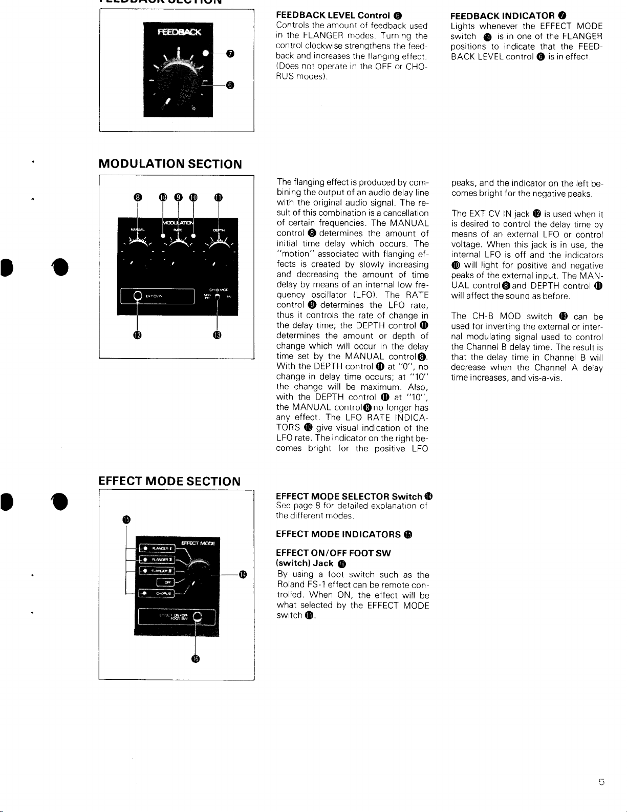
FEEDBACK LEVEL Control
Controls the amount of feedback used
in the FLANGER modes
control clockwise strengthens the feed-
back and increases the flanging effect
(Does not operate in the OFF or CHORUS modes)
.
0
. Turning the
.
FEEDBACK INDICATOR
Lights whenever the EFFECT MODE
switchmis in one of the FLANGER
positions to indicate that the FEED-
BACK LEVEL control0is in effect
0
.
MODULATION
SECTION
The flanging effect is produced by combining the output of an audio delay line
with the original audio signal
sult of this combination is a cancellation
of certain frequencies
control @ determines the amount of
initial time delay which occurs
"motion" associated with flanging effects is created by slowly increasing
and decreasing the amount of time
delay by means of an internal low fre-
quency oscillator (LFO)
control
0
thus it controls the rate of change in
the delay time
determines the amount or depth of
change which will occur in the delay
time set by the MANUAL controlO
With the DEPTH control
change in delay time occurs
the change will be maximum
with the DEPTH control0at
the MANUAL controlOno longer has
any effect
TORSmgive visual indication of the
LFO rate
comes bright for the positive LFO
determines the LFO rate,
; the DEPTH control
. The LFO RATE INDICA-
. The indicator on the right be-
. The re-
. The MANUAL
. The
. The RATE
at "0",
0
; at "10"
. Also,
"10",
0
no
peaks, and the indicator on the left becomes bright for the negative peaks
The EXT CV IN jack
is desired to control the delay time by
means of an external LFO or control
voltage
internal LFO is off and the indicators
0
will light for positive and negative
peaks of the external input
UAL controlOand DEPTH control
will affect the sound as before
The CH-B MOD switch ® can be
used for inverting the external or internal modulating signal used to control
the Channel B delay time
.
that the delay time in Channel B will
decrease when the Channel A delay
time increases, and vis-a-vis
.
0
is used when it
. When this jack is in use, the
. The MAN-
m
.
. The result is
.
EFFECT MODE SECTION
EFFECT MODE SELECTOR Switch
See page 8 for detailed explanation of
the different modes
EFFECT MODE INDICATORS
EFFECT ON/OFF FOOT SW
(switch) Jack
By using a foot switch such as the
Roland FS-1 effect can be remote con-
trolled
. When ON, the effect will be
what selected by the EFFECT MODE
switch ®
.
.
0
5
Page 3

~
~
~
~
~
~
PHASE and OUTPUT SECTIONS
CHANNEL A PHASE
CHANNEL B PHASE
At INV, the flanging effect will become
weak for the fundamental of the sound,
but strong for the overtones
OUTPUT LEVEL
Set to match the input level of the
device connected to the OUTPUT
jacks
0 4D
Switch
Switch
Switch
0
m
m
.
CHANNEL A OUTPUT Jack
CHANNEL B OUTPUT Jack
POWER Switch
with indicator
®
REAR PANEL
CHANNEL A INPUT Jack
CHANNEL B INPUT Jack
When connections are made simultaneously to both front and rear panel
inputs, the front panel jacks have
priority
. This means that in the studio,
the rear panel jacks can be used for the
studio normal connections and the
front panel jacks for temporary patching
.
(A
©
CHANNEL A OUTPUT Jack
CHANNEL
As with the inputs, the front panel
jacks have priority
B OUTPUT Jack
.
©
GND
(ground)
For making common ground connections with other equipment
Terminal
C
.
6
6
Page 4

The first flanging effects in recording
studios were produced by feeding an
audio signal to two tape recorders and
mixing the outputs from the playback
. If a light finger pressure is ap-
heads
plied to the supply reel on one of the
machines, it will run slightly slower,
thus giving a slight delay to one of the
. When this slightly delayed
outputs
sound is mixed with nondelayed sound,
the result is that certain frequencies
are cancelled
the effect which can be heard when
standing near a runway as a jet plane
takes off
cancelled as the direct sound from the
plane is combined with the delayed
sound reflected from the runway
amount of delay changes as the plane
moves off into the distance
studio, this effect is known as flanging
because it was first produced by finger
pressure applied to the flange of the
tape reel
. The effect is similar to
. Certain frequencies are
. The
. In the
.
Modern digital technology has made it
possible to design solid state audio
delay lines which can be used to imitate
the original tape flanging effect
output of the delay line is combined
with the original signal source
actual frequencies which are cancelled
as a result of this combination will
depend on the amount of the time
used
. In most flangers, the delay time
is controlled by an internal low frequency oscillator (LFO) which sweeps
the delay time above and below a pre-
determined center delay time
SBF-325 the MANUAL control Q is
used to set this initial center delay time,
thus it determines the initial frequency
cancellations which will occur
RATE control©controls the frequency
of the internal LFO, thus it controls the
rate of the delay time changes
DEPTH control
away from the center frequency posi-
tion the time delay will vary
BACK control®induces positive feedback into the circuit which tends to accent the flanging effect
determines how far
m
.
. The
. The
. In the
. The
. The
. The FEED-
7
Page 5

i nC rLMI
FLANGER
.
Cn vrCnM
I
nvu rowluta
Monaural flanging mode
In this mode, the Channel B delay line
is not used and the Channel A delay
line output is connected to both OUTPUTjacks
Stereo flanging mode
Produces a wide three-dimensional
effect using two independent delay
lines
duced by putting the CH-B MOD
switch ® in the INV (invert) position
00
FLANGER
. A "seesaw" effect can be pro-
II
.
.
.
Example setting for a strong flanging
effect
. Set
. CENTER FREQ control
as desired
Example settings for stereo flanging
.
*If both INPUTS
.
•
0©
are used when
in the FLANGER I mode, the CHANNEL A INPUT jack0will have priority
Also, the CH-B MOD switch ® and
the CHANNEL B PHASE switch
have no effect
Using only one output for monaural
sound produces an effect like that of
the FLANGER I mode
.
.
.
0
FLANGER III
Cross-mixing stereo flanging mode
A stereo flanging effect using the two
delay lines and a panning effect to pro-
duce wide, space filling sound
CHORUS
Chorus mode
This mode produces chorus sounds by
means of the delay lines
.
.
.
.
The effect is a little like phase shifted
sound with the addition of a light
depth giving chorus effect
the FEEDBACK control0will produce
large changes in the sound
MANUAL control@
Set at a relatively low position in relation to the fundamental (pitch) of the
input sound
•
When using in the monaural mode,
the effect is similar to that of the
. Changing
.
.
FLANGER II mode sound
~
T
he
FEEDBACK control@ does not
work in the CHORUS mode
.
.
it
RATE control0:
Counterclockwise
lessened
Clockwise
When using CHORUS in stereo, the
CH B MOD switch ® is often set at
H
INV
.
: chorus effect is
: chorus effect with vibrato
.
 Loading...