

Page 1
Copyright © 2013 ROLAND CORPORATION
All rights reserved. No part of this publication may be reproduced in any form without the written permission of
ROLAND CORPORATION.
Page 2
USING THE UNIT SAFELY
Before using this unit, carefully read the sections entitled: “USING THE UNIT SAFELY” and “IMPORTANT NOTES” ( p. 2; p. 4). These sections provide
important information concerning the proper operation of the unit. Additionally, in order to feel assured that you have gained a good grasp of every
feature provided by your new unit, Owner’s manual should be read in its entirety. The manual should be saved and kept on hand as a convenient
reference.
About WARNING and CAUTION Notices
Used for instructions intended to alert the
user to the risk of death or severe injury
should the unit be used improperly.
Used for instructions intended to alert the
user to the risk of injury or material
damage should the unit be used
improperly.
* Material damage refers to damage or
other adverse effects caused with
respect to the home and all its
furnishings, as well to domestic animals
or pets.
ALWAYS OBSERVE THE FOLLOWING
WARNING
Concerning the AUTO OFF function
The power to this unit will be
turned o automatically after a
predetermined amount of time has
passed since its buttons or controls
were last operated (AUTO OFF
function). If you do not want the
power to be turned o automatically,
disengage the AUTO OFF function
(p. 25).
Do not disassemble or modify by yourself
Do not open (or modify in any way)
the unit or its AC adaptor.
Do not repair or replace parts by yourself
Do not attempt to repair the unit,
or replace parts within it (except
when this manual provides specic
instructions directing you to do so).
Refer all servicing to your retailer, the
nearest Roland Service Center, or an
authorized Roland distributor, as listed
on the “Information” sheet.
Do not use or store in the following types of locations
• Subject to temperature extremes
(e.g., direct sunlight in an enclosed
vehicle, near a heating duct, on top
of heat-generating equipment); or
are
• Damp (e.g., baths, washrooms, on
wet oors); or are
• Exposed to steam or smoke; or are
• Subject to salt exposure; or are
• Humid; or are
• Exposed to rain; or are
• Dusty or sandy; or are
• Subject to high levels of vibration
and shakiness.
Do not place in an unstable location
Make sure you always have the unit
placed so it is level and sure to remain
stable. Never place it on stands that
could wobble, or on inclined surfaces.
Use only the included AC adaptor and the correct
voltage
Be sure to use only the AC adaptor
included with the unit. Also, make
sure the line voltage at the installation
matches the input voltage specied
on the AC adaptor’s body. Other AC
adaptors may use a dierent polarity,
or be designed for a dierent voltage,
so their use could result in damage,
malfunction, or electric shock.
Use only the included power cord
Use only the attached power-supply
cord. Also, the included power cord
must not be used with any other
device.
Do not bend the power cord or place heavy objects
on it
Do not excessively twist or bend the
power cord, nor place heavy objects
on it. Doing so can damage the cord,
producing severed elements and short
circuits. Damaged cords are re and
shock hazards!
Avoid extended use at high volume
This unit, either alone or in
combination with an amplier and
headphones or speakers, may be
capable of producing sound levels
that could cause permanent hearing
loss. Do not operate for a long period
of time at a high volume level, or at
a level that is uncomfortable. If you
experience any hearing loss or ringing
in the ears, you should immediately
stop using the unit, and consult an
audiologist.
About the Symbols
The symbol alerts the user to important instructions or
warnings.The specific meaning of the symbol is
determined by the design contained within the triangle. In
the case of the symbol at left, it is used for general
cautions, warnings, or alerts to danger.
The symbol alerts the user to items that must never be
carried out (are forbidden). The specific thing that must
not be done is indicated by the design contained within
the circle. In the case of the symbol at left, it means that
the unit must never be disassembled.
The symbol alerts the user to things that must be
carried out. The specific thing that must be done is
indicated by the design contained within the circle. In the
case of the symbol at left, it means that the power-cord
plug must be unplugged from the outlet.
WARNING
WARNING
Don’t allow foreign objects or liquids to enter unit;
never place containers with liquid on unit
Do not place containers containing
liquid (e.g., ower vases) on this
product. Never allow foreign objects
(e.g., ammable objects, coins, wires)
or liquids (e.g., water or juice) to enter
this product. Doing so may cause
short circuits, faulty operation, or
other malfunctions.
Turn o the unit if an abnormality or malfunction
occurs
Immediately turn the unit o, remove
the AC adaptor from the outlet, and
request servicing by your retailer, the
nearest Roland Service Center, or an
authorized Roland distributor, as listed
on the “Information” sheet when:
• The AC adaptor, the power-supply
cord, or the plug has been damaged;
or
• If smoke or unusual odor occurs; or
• Objects have fallen into, or liquid has
been spilled onto the unit; or
• The unit has been exposed to rain
(or otherwise has become wet); or
• The unit does not appear to operate
normally or exhibits a marked
change in performance.
Adults must provide supervision in places where
children are present
When using the unit in locations
where children are present, be careful
so no mishandling of the unit can
take place. An adult should always be
on hand to provide supervision and
guidance.
2
Page 3
USING THE UNIT SAFELY
Overview Quick Guide Getting Ready IN/OUT/Monitor
WARNING
Do not drop or subject to strong impact
Protect the unit from strong impact.
(Do not drop it!)
Do not share an outlet with an unreasonable number
of other devices
Do not force the unit’s powersupply cord to share an outlet with
an unreasonable number of other
devices. Be especially careful when
using extension cords—the total
power used by all devices you have
connected to the extension cord’s
outlet must never exceed the power
rating (watts/amperes) for the
extension cord. Excessive loads can
cause the insulation on the cord to
heat up and eventually melt through.
Do not use overseas
Before using the unit in a foreign
country, consult with your retailer, the
nearest Roland Service Center, or an
authorized Roland distributor, as listed
on the “Information” sheet
Handle batteries carefully
• Batteries must never be recharged,
heated, taken apart, or thrown into
re or water.
• Never expose batteries to excessive
heat such as sunshine, re or the like.
• Incorrect handling of batteries,
rechargeable batteries, or a
battery charger can cause leakage,
overheating, re, or explosion.
Before use, you must read and
strictly observe all of the precautions
that accompany the batteries,
rechargeable batteries, or battery
charger.
• When using rechargeable
batteries and a charger, use only
the combination of rechargeable
batteries and charger specied by
the battery manufacturer.
CAUTION
Place in a well ventilated location
The unit and the AC adaptor should
be located so their location or position
does not interfere with their proper
ventilation.
When disconnecting an AC adaptor, grasp it by the
plug
To prevent conductor damage, always
grasp the AC adaptor by its plug when
disconnecting it from this unit or from
a power outlet.
Periodically clean the AC adaptor’s plug
At regular intervals, you should
unplug the AC adaptor and clean
it by using a dry cloth to wipe all
dust and other accumulations away
from its prongs. Also, disconnect the
power plug from the power outlet
whenever the unit is to remain unused
for an extended period of time. Any
accumulation of dust between the
power plug and the power outlet can
result in poor insulation and lead to
re.
CAUTION
Manage cables for safety
Try to prevent cords and cables from
becoming entangled. Also, all cords
and cables should be placed so they
are out of the reach of children.
Avoid climbing on top of the unit, or placing heavy
objects on it
Never climb on top of, nor place heavy
objects on the unit.
Do not connect or disconnect the AC adaptor with wet
hands
Never handle the AC adaptor or its
plugs with wet hands when plugging
into, or unplugging from, an outlet or
this unit.
Disconnect everything before moving the unit
Before moving the unit, disconnect
the AC adaptor and all cords coming
from external devices.
Unplug the AC adaptor from the outlet before
cleaning
Before cleaning the unit, turn it o
and unplug the AC adaptor from the
outlet (p. 24).
If there is a possibility of lightning strike, disconnect
the AC adaptor from the outlet
Whenever you suspect the possibility
of lightning in your area, disconnect
the AC adaptor from the outlet.
Handle batteries carefully
If used improperly, batteries may
explode or leak and cause damage
or injury. In the interest of safety,
please read and observe the following
precautions (p. 23).
• Carefully follow the installation
instructions for batteries, and
make sure you observe the correct
polarity.
• Avoid using new batteries together
with used ones. In addition, avoid
mixing dierent types of batteries.
• Remove the batteries whenever
the unit is to remain unused for an
extended period of time.
• Never keep batteries together with
metallic objects such as ballpoint
pens, necklaces, hairpins, etc.
• Used batteries must be disposed
of in compliance with whatever
regulations for their safe disposal
that may be observed in the region
in which you live.
Handle the ground terminal carefully
If you remove the screw from the
ground terminal, be sure to replace
it; don’t leave it lying around where
it could accidently be swallowed by
small children. When refastening the
screw, make that it is rmly fastened,
so it won’t come loose.
CAUTION
Precautions concerning use of phantom power supply
Always turn the phantom power o
when connecting any device other
than condenser microphones that
require phantom power. You risk
causing damage if you mistakenly
supply phantom power to dynamic
microphones, audio playback devices,
or other devices that don’t require
such power. Be sure to check the
specications of any microphone
you intend to use by referring to the
manual that came with it.
(This instrument’s phantom power: 48 V DC, 10
mA per channel)
Take care not to get burned
Batteries may reach a high
temperature; please be careful to
avoid burning yourself.
Handle leaking batteries carefully
• If uid has leaked from a battery,
make sure not to touch it with your
bare hands.
• If any of the leaking uid gets
into your eyes, the loss of vision
may result. Do not rub your eyes;
use clean water to ush them
thoroughly. Then, promptly see a
doctor.
• Burning of the skin or dermatitis may
result if uid has gotten onto your
skin or clothing. Use clean water
to ush aected areas thoroughly;
then, promptly see a doctor.
• Using a soft cloth, carefully wipe
any remaining uid from the inside
of the battery compartment. Then,
install new batteries.
Recording/Playback
Mixer Timecode File Operation USB Appendix
3
Page 4
IMPORTANT NOTES
Power Supply
• Do not connect this unit to same electrical
outlet that is being used by an electrical
appliance that is controlled by an
inverter or a motor (such as a refrigerator,
washing machine, microwave oven, or air
conditioner). Depending on the way in which
the electrical appliance is used, power supply
noise may cause this unit to malfunction
or may produce audible noise. If it is not
practical to use a separate electrical outlet,
connect a power supply noise lter between
this unit and the electrical outlet.
• The AC adaptor will begin to generate heat
after long hours of consecutive use. This is
normal, and is not a cause for concern.
• The use of an AC adaptor is recommended
as the unit’s power consumption is relatively
high. Should you prefer to use batteries,
please use the alkaline or rechargeable NiMH type.
• To prevent malfunction and equipment
failure, always make sure to turn o the
power on all your equipment before you
make any connections.
Power Supply: Use of Batteries
• When installing or replacing batteries, always
turn this unit o and disconnect any other
devices you may have connected. This way,
you can prevent malfunction and damage.
• If operating this unit on batteries, please
use alkaline batteries or rechargeable Ni-MH
batteries.
Placement
• Using the unit near power ampliers (or
other equipment containing large power
transformers) may induce hum. To alleviate
the problem, change the orientation of this
unit; or move it farther away from the source
of interference.
• This device may interfere with radio and
television reception. Do not use this device
in the vicinity of such receivers.
• Noise may be produced if wireless
communications devices, such as cell
phones, are operated in the vicinity of this
unit. Such noise could occur when receiving
or initiating a call, or while conversing.
Should you experience such problems, you
should relocate such wireless devices so they
are at a greater distance from this unit, or
switch them o.
• Do not expose the unit to direct sunlight,
place it near devices that radiate heat, leave
it inside an enclosed vehicle, or otherwise
subject it to temperature extremes. Excessive
heat can deform or discolor the unit.
• When moved from one location to another
where the temperature and/or humidity is
very dierent, water droplets (condensation)
may form inside the unit. Damage or
malfunction may result if you attempt to use
the unit in this condition. Therefore, before
using the unit, you must allow it to stand for
several hours, until the condensation has
completely evaporated.
• Depending on the material and temperature
of the surface on which you place the unit, its
rubber feet may discolor or mar the surface.
You can place a piece of felt or cloth
under the rubber feet to prevent this from
happening. If you do so, please make
sure that the unit will not slip or move
accidentally.
• Do not place containers or anything else
containing liquid on top of this unit. Also,
whenever any liquid has been spilled on the
surface of this unit, be sure to promptly wipe
it away using a soft, dry cloth.
Maintenance
• For everyday cleaning wipe the unit with a
soft, dry cloth or one that has been slightly
dampened with water. To remove stubborn
dirt, use a cloth impregnated with a mild,
non-abrasive detergent. Afterwards, be sure
to wipe the unit thoroughly with a soft, dry
cloth.
• Never use benzine, thinners, alcohol or
solvents of any kind, to avoid the possibility
of discoloration and/or deformation.
Repairs and Data
• Please be aware that all data contained in
the unit’s memory may be lost when the unit
is sent for repairs. Important data should
always be backed up USB ash drives, SD
cards, SDHC cards, or written down on paper
(when possible). During repairs, due care
is taken to avoid the loss of data. However,
in certain cases (such as when circuitry
related to memory itself is out of order), we
regret that it may not be possible to restore
the data, and Roland assumes no liability
concerning such loss of data.
Additional Precautions
• Please be aware that the contents of
memory can be irretrievably lost as a result
of a malfunction, or the improper operation
of the unit. Data stored on an SD card or
USB ash drive has a nite lifespan, and may
be lost simply with the passage of time. To
protect yourself against the risk of loosing
important data, we recommend that you
back up important data to another location
such as a computer.
• Unfortunately, it may be impossible to
restore the contents of data that was stored
in the unit’s memory, USB ash drives, SD
cards, SDHC cards, once it has been lost.
Roland Corporation assumes no liability
concerning such loss of data.
• Use a reasonable amount of care when using
the unit’s buttons, sliders, or other controls;
and when using its jacks and connectors.
Rough handling can lead to malfunctions.
• Never strike or apply strong pressure to the
display.
• When disconnecting all cables, grasp the
connector itself—never pull on the cable.
This way you will avoid causing shorts, or
damage to the cable’s internal elements.
• To avoid disturbing others nearby, try to
keep the unit’s volume at reasonable levels.
• When you need to transport the unit,
package it in the box (including padding)
that it came in, if possible. Otherwise, you
will need to use equivalent packaging
materials.
• Some connection cables contain resistors.
Do not use cables that incorporate resistors
for connecting to this unit. The use of such
cables can cause the sound level to be
extremely low, or impossible to hear. For
information on cable specications, contact
the manufacturer of the cable.
Using External Memories
• USB ash drives, SD cards, SDHC cards, are
constructed using precision components;
handle the memories, cards carefully, paying
particular note to the following.
• To prevent damage to the cards from static
electricity, be sure to discharge any static
electricity from your own body before handling
the cards.
• Do not touch or allow metal to come into
contact with the contact portion of the cards.
• Do not bend, drop, or subject cards to strong
shock or vibration.
• Do not keep cards in direct sunlight, in closed
vehicles, or other such locations.
• Do not allow cards to become wet.
• Do not disassemble or modify the cards.
Copyright
• It is forbidden by law to make an audio
recording, video recording, copy or
revision of a third party’s copyrighted work
(musical work, video work, broadcast, live
performance, or other work), whether
in whole or in part, and distribute, sell,
lease, perform, or broadcast it without the
permission of the copyright owner.
• Do not use this product for purposes that
could infringe on a copyright held by a
third party. We assume no responsibility
whatsoever with regard to any infringements
of third-party copyrights arising through
your use of this product
• This product can be used to record or
duplicate audio or visual material without
being limited by certain technological copyprotection measures. This is due to the fact
that this product is intended to be used for
the purpose of producing original music or
video material, and is therefore designed
so that material that does not infringe
copyrights belonging to others (for example,
your own original works) can be recorded or
duplicated freely.
• MMP (Moore Microprocessor Portfolio)
refers to a patent portfolio concerned with
microprocessor architecture, which was
developed by Technology Properties Limited
(TPL). Roland has licensed this technology
from the TPL Group.
• The SD logo (
) are trademarks of SD-3C, LLC.
(
• ASIO is a trademark and software of
Steinberg Media Technologies GmbH.
• This product contains eCROS integrated
software platform of eSOL Co.,Ltd. eCROS is a
trademark of eSOL Co., Ltd. in Japan.
• Company names and product names
appearing in this document are registered
trademarks or trademarks of their respective
owners.
• Roland, BOSS are either registered
trademarks or trademarks of Roland
Corporation in the United States and/or
other countries.
) and SDHC logo
4
Page 5
Contents
Overview Quick Guide Getting Ready IN/OUT/Monitor
USING THE UNIT SAFELY . . . . . . . . . . . . . . . . . . . . . . . . . . . . . . . . . . . . . . . . . . 2
IMPORTANT NOTES . . . . . . . . . . . . . . . . . . . . . . . . . . . . . . . . . . . . . . . . . . . . . . 4
Overview . . . . . . . . . . . . . . . . . . . . . . . . . . . . . . . . . . . . . . . . . . . . . . . . . . . . . . . .6
Panel Description . . . . . . . . . . . . . . . . . . . . . . . . . . . . . . . . . . . . . . . . . . . . . . . . . . . . . . . . 6
Front Panel . . . . . . . . . . . . . . . . . . . . . . . . . . . . . . . . . . . . . . . . . . . . . . . . . . . . . . . . 6
Side Panel (Left) . . . . . . . . . . . . . . . . . . . . . . . . . . . . . . . . . . . . . . . . . . . . . . . . . . . 7
Side Panel (Right) . . . . . . . . . . . . . . . . . . . . . . . . . . . . . . . . . . . . . . . . . . . . . . . . . . 8
Rear Panel . . . . . . . . . . . . . . . . . . . . . . . . . . . . . . . . . . . . . . . . . . . . . . . . . . . . . . . . . 8
Top Panel . . . . . . . . . . . . . . . . . . . . . . . . . . . . . . . . . . . . . . . . . . . . . . . . . . . . . . . . . 9
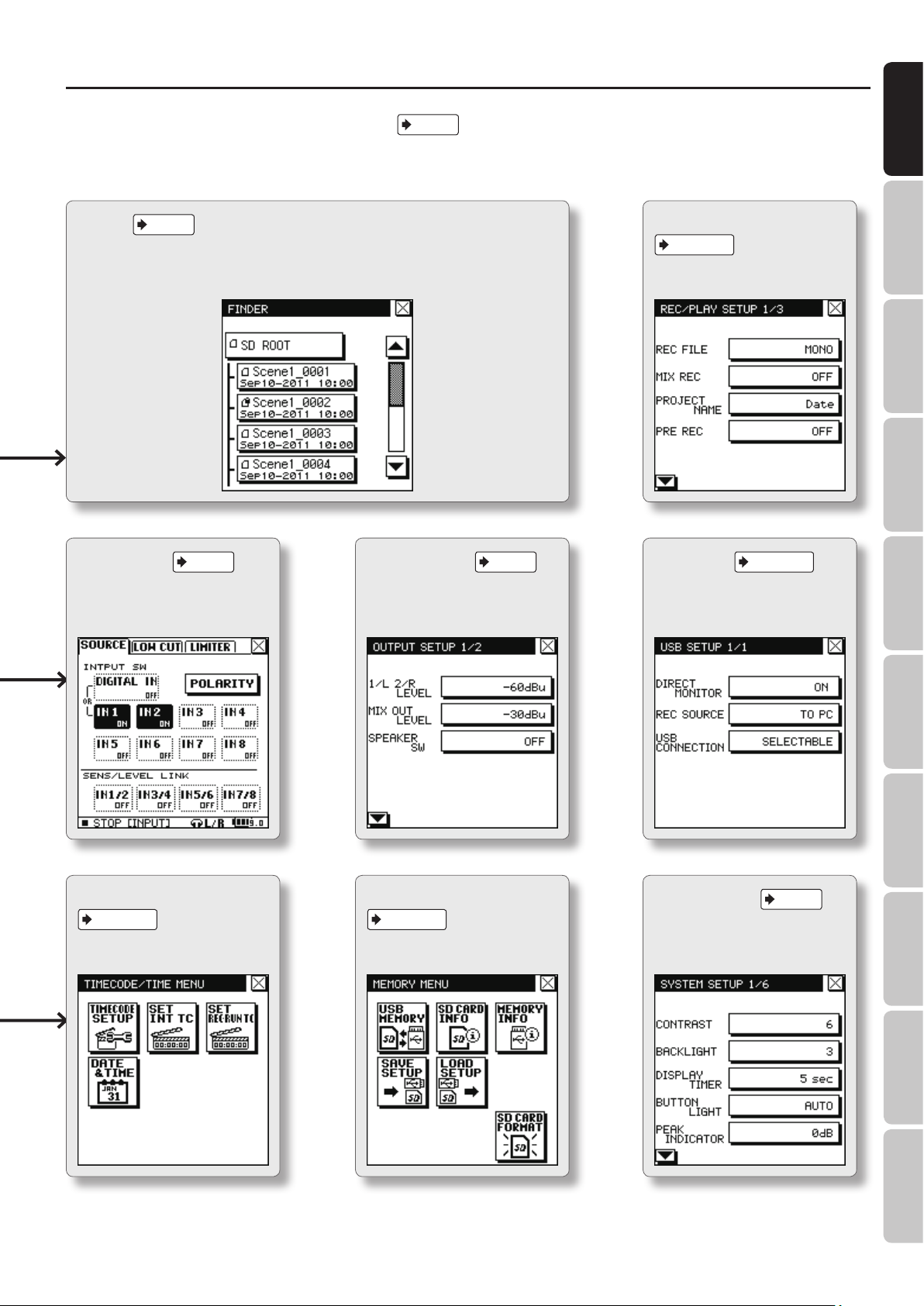
Items in the Screen . . . . . . . . . . . . . . . . . . . . . . . . . . . . . . . . . . . . . . . . . . . . . . . . . . . . . .10
Home Screen . . . . . . . . . . . . . . . . . . . . . . . . . . . . . . . . . . . . . . . . . . . . . . . . . . . . .10
MENU Screen . . . . . . . . . . . . . . . . . . . . . . . . . . . . . . . . . . . . . . . . . . . . . . . . . . . . .12
What Is a Project? . . . . . . . . . . . . . . . . . . . . . . . . . . . . . . . . . . . . . . . . . . . . . . . . . . . . . . .14
Project File Structure . . . . . . . . . . . . . . . . . . . . . . . . . . . . . . . . . . . . . . . . . . . . .14
BWF and iMXL . . . . . . . . . . . . . . . . . . . . . . . . . . . . . . . . . . . . . . . . . . . . . . . . . . . .14
Quick Guide . . . . . . . . . . . . . . . . . . . . . . . . . . . . . . . . . . . . . . . . . . . . . . . . . . . .15
Setup . . . . . . . . . . . . . . . . . . . . . . . . . . . . . . . . . . . . . . . . . . . . . . . . . . . . . . . . . .23
Preparing the Power Supply . . . . . . . . . . . . . . . . . . . . . . . . . . . . . . . . . . . . . . . . . . . . .23
Installing Batteries . . . . . . . . . . . . . . . . . . . . . . . . . . . . . . . . . . . . . . . . . . . . . . . .23
Connecting the AC adaptor . . . . . . . . . . . . . . . . . . . . . . . . . . . . . . . . . . . . . . .24
Using External Power Sources . . . . . . . . . . . . . . . . . . . . . . . . . . . . . . . . . . . . .24
Turning the Power On/O . . . . . . . . . . . . . . . . . . . . . . . . . . . . . . . . . . . . . . . . 25
Preventing the Power from Automatically Turning O (AUTO OFF) .25
Setting the Date and Time . . . . . . . . . . . . . . . . . . . . . . . . . . . . . . . . . . . . . . . . . . . . . . .26
SD Card . . . . . . . . . . . . . . . . . . . . . . . . . . . . . . . . . . . . . . . . . . . . . . . . . . . . . . . . . . . . . . . . .26
Inserting an SD Card . . . . . . . . . . . . . . . . . . . . . . . . . . . . . . . . . . . . . . . . . . . . . .26
Formatting an SD Card . . . . . . . . . . . . . . . . . . . . . . . . . . . . . . . . . . . . . . . . . . . .27
Removing an SD Card. . . . . . . . . . . . . . . . . . . . . . . . . . . . . . . . . . . . . . . . . . . . .27
Input Settings . . . . . . . . . . . . . . . . . . . . . . . . . . . . . . . . . . . . . . . . . . . . . . . . . .28
Input Settings . . . . . . . . . . . . . . . . . . . . . . . . . . . . . . . . . . . . . . . . . . . . . . . . . . . . . . . . . . .28
Input Source Settings . . . . . . . . . . . . . . . . . . . . . . . . . . . . . . . . . . . . . . . . . . . .28
Connections . . . . . . . . . . . . . . . . . . . . . . . . . . . . . . . . . . . . . . . . . . . . . . . . . . . . . . . . . . . . 28
Audio Input from a Digital Device . . . . . . . . . . . . . . . . . . . . . . . . . . . . . . . . .29
Low Cut Filter Settings . . . . . . . . . . . . . . . . . . . . . . . . . . . . . . . . . . . . . . . . . . .29
Limiter Settings . . . . . . . . . . . . . . . . . . . . . . . . . . . . . . . . . . . . . . . . . . . . . . . . . .30
Input Level and Input Sensitivity Settings . . . . . . . . . . . . . . . . . . . . . . . . . . . . . . . .31
Output Settings . . . . . . . . . . . . . . . . . . . . . . . . . . . . . . . . . . . . . . . . . . . . . . . . . 32
Output Settings . . . . . . . . . . . . . . . . . . . . . . . . . . . . . . . . . . . . . . . . . . . . . . . . . . . . . . . . .32
Switching the Output Level of the Analog Output Jacks (MIX L/
OUT 1, MIX R/OUT 2) . . . . . . . . . . . . . . . . . . . . . . . . . . . . . . . . . . . . . . . . . . . . . .
Connections . . . . . . . . . . . . . . . . . . . . . . . . . . . . . . . . . . . . . . . . . . . . . . . . . . . . . . . . . . . . 32
Switching the Maximum Output Level of the MIX OUT (STEREO)
jack . . . . . . . . . . . . . . . . . . . . . . . . . . . . . . . . . . . . . . . . . . . . . . . . . . . . . . . . . . . . . .
Selecting the Output Audio for OUT 1/2, 3/4, 5/6, and 7/8 . . . . . . . . . .33
Switching the Internal Speakers ON/OFF . . . . . . . . . . . . . . . . . . . . . . . . . .33
32
33
Monitor Settings . . . . . . . . . . . . . . . . . . . . . . . . . . . . . . . . . . . . . . . . . . . . . . . .34
Monitor Screen . . . . . . . . . . . . . . . . . . . . . . . . . . . . . . . . . . . . . . . . . . . . . . . . . . . . . . . . . .34
Settings for Headphone Monitoring . . . . . . . . . . . . . . . . . . . . . . . . . . . . . . .34
PFL (Pre Fader Listen) . . . . . . . . . . . . . . . . . . . . . . . . . . . . . . . . . . . . . . . . . . . . .34
REALTIME ANALYZER . . . . . . . . . . . . . . . . . . . . . . . . . . . . . . . . . . . . . . . . . . . . . 34
Recording/Playback . . . . . . . . . . . . . . . . . . . . . . . . . . . . . . . . . . . . . . . . . . . . .35
Recording Settings . . . . . . . . . . . . . . . . . . . . . . . . . . . . . . . . . . . . . . . . . . . . . . . . . . . . . .35
Specifying the Input (Recording) Channels . . . . . . . . . . . . . . . . . . . . . . . .35
Selecting the Audio File Type . . . . . . . . . . . . . . . . . . . . . . . . . . . . . . . . . . . . .35
MIX REC . . . . . . . . . . . . . . . . . . . . . . . . . . . . . . . . . . . . . . . . . . . . . . . . . . . . . . . . . .35
Choosing the Project Naming Method . . . . . . . . . . . . . . . . . . . . . . . . . . . .35
Pre-Recording . . . . . . . . . . . . . . . . . . . . . . . . . . . . . . . . . . . . . . . . . . . . . . . . . . . .36
Sampling Rate . . . . . . . . . . . . . . . . . . . . . . . . . . . . . . . . . . . . . . . . . . . . . . . . . . . .36
Bit Depth . . . . . . . . . . . . . . . . . . . . . . . . . . . . . . . . . . . . . . . . . . . . . . . . . . . . . . . . .37
Basic Operation for Recording . . . . . . . . . . . . . . . . . . . . . . . . . . . . . . . . . . . . . . . . . . .37
Marker . . . . . . . . . . . . . . . . . . . . . . . . . . . . . . . . . . . . . . . . . . . . . . . . . . . . . . . . . . . . . . . . . .38
Basic Operation for Playback . . . . . . . . . . . . . . . . . . . . . . . . . . . . . . . . . . . . . . . . . . . .39
Playback Settings . . . . . . . . . . . . . . . . . . . . . . . . . . . . . . . . . . . . . . . . . . . . . . . . . . . . . . .39
PLAY MODE . . . . . . . . . . . . . . . . . . . . . . . . . . . . . . . . . . . . . . . . . . . . . . . . . . . . . .39
PLAY REPEAT . . . . . . . . . . . . . . . . . . . . . . . . . . . . . . . . . . . . . . . . . . . . . . . . . . . . .40
AB REPEAT . . . . . . . . . . . . . . . . . . . . . . . . . . . . . . . . . . . . . . . . . . . . . . . . . . . . . . .40
MS Mic Settings . . . . . . . . . . . . . . . . . . . . . . . . . . . . . . . . . . . . . . . . . . . . . . . . . . . . . . . . .41
MS MIC DECODER . . . . . . . . . . . . . . . . . . . . . . . . . . . . . . . . . . . . . . . . . . . . . . . .41
MS-MIC LEVEL . . . . . . . . . . . . . . . . . . . . . . . . . . . . . . . . . . . . . . . . . . . . . . . . . . . .41
MS-MIC WIDE . . . . . . . . . . . . . . . . . . . . . . . . . . . . . . . . . . . . . . . . . . . . . . . . . . . . .41
Using a Footswitch to Remotely Control Recording or Playback . . . . . . . . . . .42
Assigning a Function to the Footswitch . . . . . . . . . . . . . . . . . . . . . . . . . . .42
Mixer . . . . . . . . . . . . . . . . . . . . . . . . . . . . . . . . . . . . . . . . . . . . . . . . . . . . . . . . . . .43
MIXER Screen . . . . . . . . . . . . . . . . . . . . . . . . . . . . . . . . . . . . . . . . . . . . . . . . . . . . . . . . . . . 43
Adjusting the MIX LEVEL . . . . . . . . . . . . . . . . . . . . . . . . . . . . . . . . . . . . . . . . . . . . . . . . . 43
PAN . . . . . . . . . . . . . . . . . . . . . . . . . . . . . . . . . . . . . . . . . . . . . . . . . . . . . . . . . . . . . . . . . . . . .44
MUTE ON/OFF . . . . . . . . . . . . . . . . . . . . . . . . . . . . . . . . . . . . . . . . . . . . . . . . . . . . . . . . . .44
LINK ON/OFF . . . . . . . . . . . . . . . . . . . . . . . . . . . . . . . . . . . . . . . . . . . . . . . . . . . . . . . . . . . .45
EQ ON/OFF . . . . . . . . . . . . . . . . . . . . . . . . . . . . . . . . . . . . . . . . . . . . . . . . . . . . . . . . . . . . .45
Editing the EQ . . . . . . . . . . . . . . . . . . . . . . . . . . . . . . . . . . . . . . . . . . . . . . . . . . . .45
MASTER LIMITER . . . . . . . . . . . . . . . . . . . . . . . . . . . . . . . . . . . . . . . . . . . . . . . . . . . . . . . . 46
Adjusting the Output Level . . . . . . . . . . . . . . . . . . . . . . . . . . . . . . . . . . . . . . . . . . . . . .46
Recording a Two-channel Mix . . . . . . . . . . . . . . . . . . . . . . . . . . . . . . . . . . . . . . . . . . . .46
TIMECODE . . . . . . . . . . . . . . . . . . . . . . . . . . . . . . . . . . . . . . . . . . . . . . . . . . . . . .47
TIMECODE MODE . . . . . . . . . . . . . . . . . . . . . . . . . . . . . . . . . . . . . . . . . . . . . . . . . . . . . . .47
FRAME RATE . . . . . . . . . . . . . . . . . . . . . . . . . . . . . . . . . . . . . . . . . . . . . . . . . . . . . . . . . . . .48
TIMECODE OUTPUT . . . . . . . . . . . . . . . . . . . . . . . . . . . . . . . . . . . . . . . . . . . . . . . . . . . . .48
Internal Timecode . . . . . . . . . . . . . . . . . . . . . . . . . . . . . . . . . . . . . . . . . . . . . . . . . . . . . . .49
Manually Jamming to External Timecode. . . . . . . . . . . . . . . . . . . . . . . . . . . . . . . . .49
Specifying the REC-RUN Start Time . . . . . . . . . . . . . . . . . . . . . . . . . . . . . . . . . . . . . . .49
SLATE . . . . . . . . . . . . . . . . . . . . . . . . . . . . . . . . . . . . . . . . . . . . . . . . . . . . . . . . . .50
SLATE TONE . . . . . . . . . . . . . . . . . . . . . . . . . . . . . . . . . . . . . . . . . . . . . . . . . . . . . . . . . . . . .50
Specifying the Output Destination for the Slate Tone . . . . . . . . . . . . . .50
SLATE MIC . . . . . . . . . . . . . . . . . . . . . . . . . . . . . . . . . . . . . . . . . . . . . . . . . . . . . . . . . . . . . .50
Using the Slate Mic to Record on Desired Tracks of the Recorder . . .50
Project and Folder Operations . . . . . . . . . . . . . . . . . . . . . . . . . . . . . . . . . . .51
Basic Operation in the Finder . . . . . . . . . . . . . . . . . . . . . . . . . . . . . . . . . . . . . . . . . . . .51
Opening a Project . . . . . . . . . . . . . . . . . . . . . . . . . . . . . . . . . . . . . . . . . . . . . . . . . . . . . . .52
Copying a Project . . . . . . . . . . . . . . . . . . . . . . . . . . . . . . . . . . . . . . . . . . . . . . . . . . . . . . . 52
Moving a Project . . . . . . . . . . . . . . . . . . . . . . . . . . . . . . . . . . . . . . . . . . . . . . . . . . . . . . . .53
Deleting a Project or Folder . . . . . . . . . . . . . . . . . . . . . . . . . . . . . . . . . . . . . . . . . . . . . .53
Renaming a Project or Folder . . . . . . . . . . . . . . . . . . . . . . . . . . . . . . . . . . . . . . . . . . . .54
Viewing Information About the Project . . . . . . . . . . . . . . . . . . . . . . . . . . . . . . . . . .54
Protecting a Project (Protect). . . . . . . . . . . . . . . . . . . . . . . . . . . . . . . . . . . . . .54
Repairing a Project . . . . . . . . . . . . . . . . . . . . . . . . . . . . . . . . . . . . . . . . . . . . . . . . . . . . . .55
Creating a Folder/Sorting Projects . . . . . . . . . . . . . . . . . . . . . . . . . . . . . . . . . . . . . . .55
Creating a Folder at the Root Directory . . . . . . . . . . . . . . . . . . . . . . . . . . . .55
Creating a Folder Within a Folder . . . . . . . . . . . . . . . . . . . . . . . . . . . . . . . . . .56
Sorting Projects . . . . . . . . . . . . . . . . . . . . . . . . . . . . . . . . . . . . . . . . . . . . . . . . . .56
Backing Up and Loading the R-88’s Settings . . . . . . . . . . . . . . . . . . . . . .58
Creating a Backup . . . . . . . . . . . . . . . . . . . . . . . . . . . . . . . . . . . . . . . . . . . . . . . . . . . . . . .58
Loading a Backup into the R-88 . . . . . . . . . . . . . . . . . . . . . . . . . . . . . . . . . . . . . . . . . .58
Viewing Information About the Media . . . . . . . . . . . . . . . . . . . . . . . . . . . . . . . . . . .58
Copying a Project to USB Flash Drive / Loading from USB Flash
Drive . . . . . . . . . . . . . . . . . . . . . . . . . . . . . . . . . . . . . . . . . . . . . . . . . . . . . . . . . . .59
Copying a Project . . . . . . . . . . . . . . . . . . . . . . . . . . . . . . . . . . . . . . . . . . . . . . . . . . . . . . . 59
Connecting to Your Computer via USB . . . . . . . . . . . . . . . . . . . . . . . . . . .60
USB Connection Mode Setting . . . . . . . . . . . . . . . . . . . . . . . . . . . . . . . . . . . . . . . . . . .60
Exchanging Files With Your Computer (Storage) . . . . . . . . . . . . . . . . . . . . . . . . . .61
Connecting the R-88 to Your Computer. . . . . . . . . . . . . . . . . . . . . . . . . . . .61
Disconnecting from Your Computer . . . . . . . . . . . . . . . . . . . . . . . . . . . . . . .62
Using the R-88 as an Audio Interface . . . . . . . . . . . . . . . . . . . . . . . . . . . . . . . . . . . . .63
Block Diagram for Audio Interface Connection . . . . . . . . . . . . . . . . . . . .63
Installing the USB Driver . . . . . . . . . . . . . . . . . . . . . . . . . . . . . . . . . . . . . . . . . .64
Simultaneous Recording on the R-88 Itself . . . . . . . . . . . . . . . . . . . . . . . .64
Listening to the Computer’s Playback Through the R-88 . . . . . . . . . . . .64
Parameter List . . . . . . . . . . . . . . . . . . . . . . . . . . . . . . . . . . . . . . . . . . . . . . . . . .65
Error Messages . . . . . . . . . . . . . . . . . . . . . . . . . . . . . . . . . . . . . . . . . . . . . . . . .69
Troubleshooting . . . . . . . . . . . . . . . . . . . . . . . . . . . . . . . . . . . . . . . . . . . . . . . .70
Specications . . . . . . . . . . . . . . . . . . . . . . . . . . . . . . . . . . . . . . . . . . . . . . . . . . .72
R-88 Block Diagram . . . . . . . . . . . . . . . . . . . . . . . . . . . . . . . . . . . . . . . . . . . . .74
Index . . . . . . . . . . . . . . . . . . . . . . . . . . . . . . . . . . . . . . . . . . . . . . . . . . . . . . . . . . .77
Recording/Playback
Mixer Timecode File Operation USB Appendix
5
Page 6
Overview
Panel Description
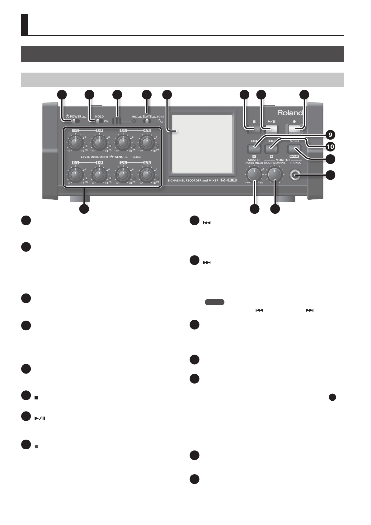
Front Panel
1 2 53 4 6 7 8
9
10
11
12
13
1
[POWER] switch
Slide this switch in the direction of the arrow to turn the power on/
o (p. 25).
2
[HOLD] switch
When the power is on, setting the [HOLD] switch in the ON position
will disable operation of the knobs, buttons, touch panel, and
master level. Disabling these controls will help prevent unintended
operation.
You can specify which controls to disable by using <SYSTEM
SETUP>Ú<HOLD> (p. 66).
3
SLATE MIC
This mic allows you to break into the input audio and record
comments such as credits or take numbers (p. 50).
4
[SLATE] switch
This switch turns on the slate mic or outputs a slate tone (p. 50). If
you slide the switch to the “MIC” position and hold it there for two
seconds, the slate mic will turn on. If you slide the switch to the
“TONE” position and hold it there for two seconds, a slate tone will
be output.
5
Touch panel display
This touch panel shows various information for the R-88, and also
allows you to make settings and perform operations (p. 10).
6
[ ] (STOP) button
This button stops playback or recording.
7
[ ] (PLAY/PAUSE) button
Press this button to start playback, or to pause playback or
recording.
8
[ ] (REC) button
This button starts recording. During recording, the indicator will
light. If you pause during recording, the indicator will blink.
6
14 15
9
[ ] (−) button
Press this button to move to the beginning of the project, or to
select the previous project. By holding down this button, you can
rewind through the project. You can do this during playback or
while stopped. When making various settings on the R-88, this
button decreases the value of the selected parameter.
10
[ ] (+) button
Press this button to select the next project. By holding down
this button, you can fast-forward through the project. You can
do this during playback or while stopped. When making various
settings on the R-88, this button increases the value of the selected
parameter.
MEMO
If you press both the [
the selected value will return to its default setting.
11
[MENU] (HOME) button
This button lets you make various settings for the R-88, such as
recording/playback settings and specifying the date and time (p. 12).
If the home screen is not displayed, this button takes you back to
the home screen.
12
PHONES jack
You can connect headphones here (p. 32).
13
[LEVEL]/[SENS] knob (1/L–8/R),
] (−) button and the [ ] (+) button,
PK (PEAK) indicator
These knobs adjust the input levels from the XLR input jacks
(1/L–8/R) located on the right side panel (p. 31). The inner knob
adjusts LEVEL, and the outer ring adjusts SENS.
The [LEVEL] knobs can be switched between two functions: input
level setting or mixer fader (Level Knob Mode p. 43).
The PK (PEAK) indicator at the right of each knob will light when the
input volume is excessive.
You can change the level at which the PK indicator will light
(SYSTEM SETUP–PEAK INDICATOR p. 66).
14
[MASTER] knob
This knob adjusts the output volume of the mixer. Press this knob to
access the mixer edit screen (p. 43).
15
[MONITOR] knob
This knob adjusts the volume of the headphones and speakers.
Press this knob to access the monitor setting screen (Headphone
setting/PFL /REALTIME ANALYZER).
25
Page 7
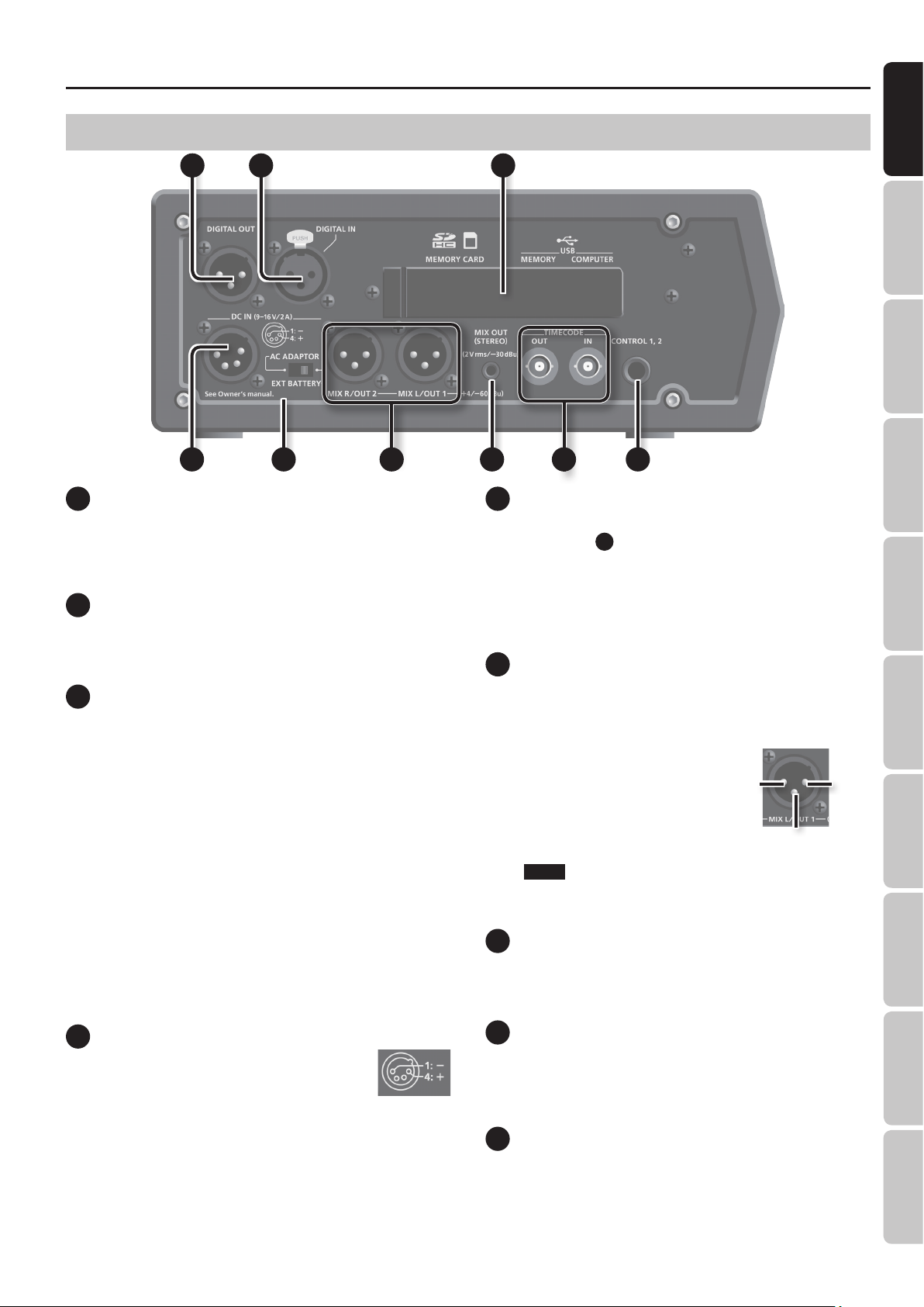
Side Panel (Left)
Overview
Overview Quick Guide Getting Ready IN/OUT/Monitor
16
17 18
19 20 22 24
16
DIGITAL OUT jack
This jack outputs a digital signal. You can connect digital devices,
such as speakers or mixers, with an XLR type cable (AES/EBU, IEC
60958-4 compliant). The internal mixer’s two-channel mix is output
here as a digital signal.
17
DIGITAL IN jack
If you want to record a digital signal, connect a XLR type cable to
this jack. The digital input signal is recorded in stereo with the L
channel on track 1 and the R channel on track 2.
18
Rubber ap
Open this cover to expose the SD card slot, USB MEMORY port,
and USB COMPUTER port.
SD card slot
Insert the SD card into this slot (p. 26).
USB MEMORY port
You can connect a commercially available USB ash drive to this
port. A project recorded on the R-88 can be copied to your USB
ash drive as a backup. A backup from your USB ash drive can also
be loaded into the R-88.
USB COMPUTER port
Use a commercially available USB cable to connect this to your
computer. This allows projects recorded on the R-88 to be
transferred to your computer, or WAV les from your computer to
be copied to the R-88 for playback (p. 60).
You can also use the R-88 as a USB audio interface (p. 63).
2321
20
External power supply select switch
This switch selects the type of external power supply connected to
the DC IN jack
Set this to the AC ADAPTOR position if using an AC adaptor, or
to EXT BATTERY if using a commercially available external power
supply.
* If this is set to EXT BATTERY, you must specify the nal voltage
(p. 24).
21
Analog Output (MIX L/OUT 1, MIX R/OUT 2) jacks
These are XLR balanced output jacks. As the audio output, you can
select either specic tracks or the output of the internal mixer (twochannel mix). You can switch the output level (+4 dBu/-60 dBu). For
details, refer to “Output Settings” (p. 32).
* This instrument is equipped with
balanced (XLR) type jacks. Wiring
diagrams for these jacks are
shown at right. Make connections
after rst checking the wiring
diagrams of other equipment you
intend to connect.
NOTE
Do not supply phantom power from an external device to these
output jacks.
22
MIX OUT (STEREO) jack
This is a stereo-mini output jack. It outputs the output of the
internal mixer (two-channel mix). You can switch the output level (2
Vrms/-30 dBu). For details, refer to “Output Settings” (p. 32).
19
.
1: GND 2: HOT
3: COLD
Recording/Playback
Mixer Timecode File Operation USB Appendix
19
DC IN jack
You can connect either the included AC adaptor
or a commercially available cable for an external
power device. For details, refer to “Connecting the
AC adaptor” (p. 24), or ”Using External Power Sources”
(p. 24).
23
TIMECODE IN/OUT jacks
You can connect devices with a timecode port. This allows you to
records the timecode in the R-88 when the recording starts (IN) and
to output the R-88 internal timecode (OUT). For details on recording
the timecode, see ”TIMECODE” (p. 47).
24
CONTROL 1, 2 jack
You can connect a footswitch here (BOSS FS-6 or FS-5U; sold
separately), then use it to control playback, recording, or rewind (p.
42).
7
Page 8
Overview
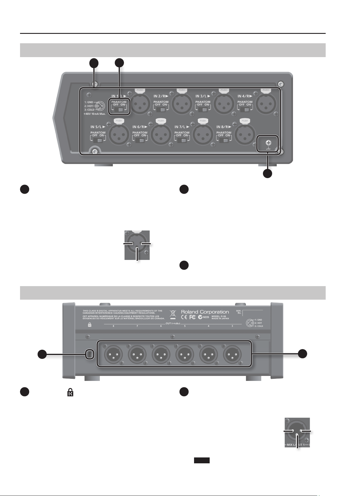
Side Panel (Right)
25
25
Analog input (IN 1/L–IN 8/R) jacks
These are analog audio input jacks equipped with mic preamps.
Each of the XLR input jacks 1-8 can be used as a monaural input,
providing a total of 8 input channels. Alternatively, XLR input jacks 1
and 2, 3 and 4, 5 and 6, and 7 and 8 can be used as four stereo-input
channels. For details, refer to “Input Settings” (p. 28).
* This instrument is equipped with
balanced (XLR) type jacks. Wiring
diagrams for these jacks are
shown at right. Make connections
after rst checking the wiring
diagrams of other equipment you
intend to connect.
26
2: HOT 1: GND
3: COLD
27
26
[PHANTOM] switch
These switches turn on/o the phantom power that is supplied to
each XLR input jack.
* Always turn the phantom power o when connecting any
device other than condenser microphones that require
phantom power. You risk causing damage if you mistakenly
supply phantom power to dynamic microphones, audio
playback devices, or other devices that don’t require such
power. Be sure to check the specications of any microphone
you intend to use by referring to the manual that came with it.
(This instrument’s phantom power: 48 V DC, 10 mA per channel)
27
Ground Terminal
Refer to “About the Ground Terminal” (p. 9).
Rear Panel
28
28
Security slot ( )
You can attach a commercial available security cable to this slot to
prevent theft.
http://www.kensington.com/
8
29
Analog Output (OUT 3–OUT 8) jack
These are XLR balanced output jacks. As the audio output signal,
you can choose either specic tracks or the output of the internal
mixer (two-channel mix). The output level is xed at +4 dBu.
* This instrument is equipped with
balanced (XLR) type jacks. Wiring
diagrams for these jacks are
shown at right. Make connections
after rst checking the wiring
diagrams of other equipment you
intend to connect.
NOTE
Do not supply phantom power from an external device to these
output jacks.
1: GND 2: HOT
3: COLD
29
Page 9
Top Panel
30
31
Overview
Overview Quick Guide Getting Ready IN/OUT/Monitor
Recording/Playback
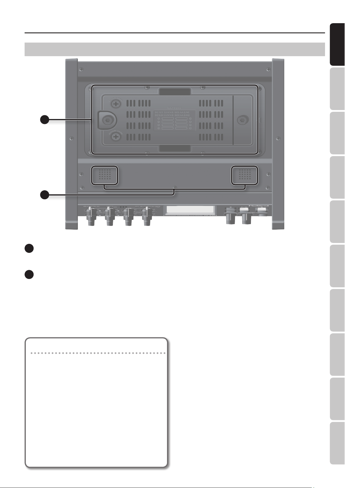
30
Battery case
Install batteries here. The entire battery case can be removed and
installed with the batteries (p. 23).
31
Internal speakers
These are built-in speakers for monitoring. If you want to hear
sound from the internal speakers, access the MENU item OUTPUT
SETUP, and turn SPEAKER SW “ON.” For details, refer to “Switching
the Internal Speakers ON/OFF” (p. 33).
* No sound will be output while using headphones or while
recording.
About the Ground Terminal (p. 8)
Depending on the circumstances of a particular setup, you
may experience a discomforting sensation, or perceive that
the surface feels gritty to the touch when you touch this
device, microphones connected to it, or the metal portions of
other objects. This is due to an innitesimal electrical charge,
which is absolutely harmless. However, if you are concerned
about this, connect the ground terminal (p. 8) with an external
ground. When the unit is grounded, a slight hum may occur,
depending on the particulars of your installation. If you
are unsure of the connection method, contact the nearest
Roland Service Center, or an authorized Roland distributor, as
listed on the “Information” sheet
* Unsuitable places for connection
• Water pipes (may result in shock or electrocution)
• Gas pipes (may result in re or explosion)
• Telephone-line ground or lightning rod (may be
dangerous in the event of lightning)
Mixer Timecode File Operation USB Appendix
9
Page 10
Overview
Items in the Screen
Home Screen
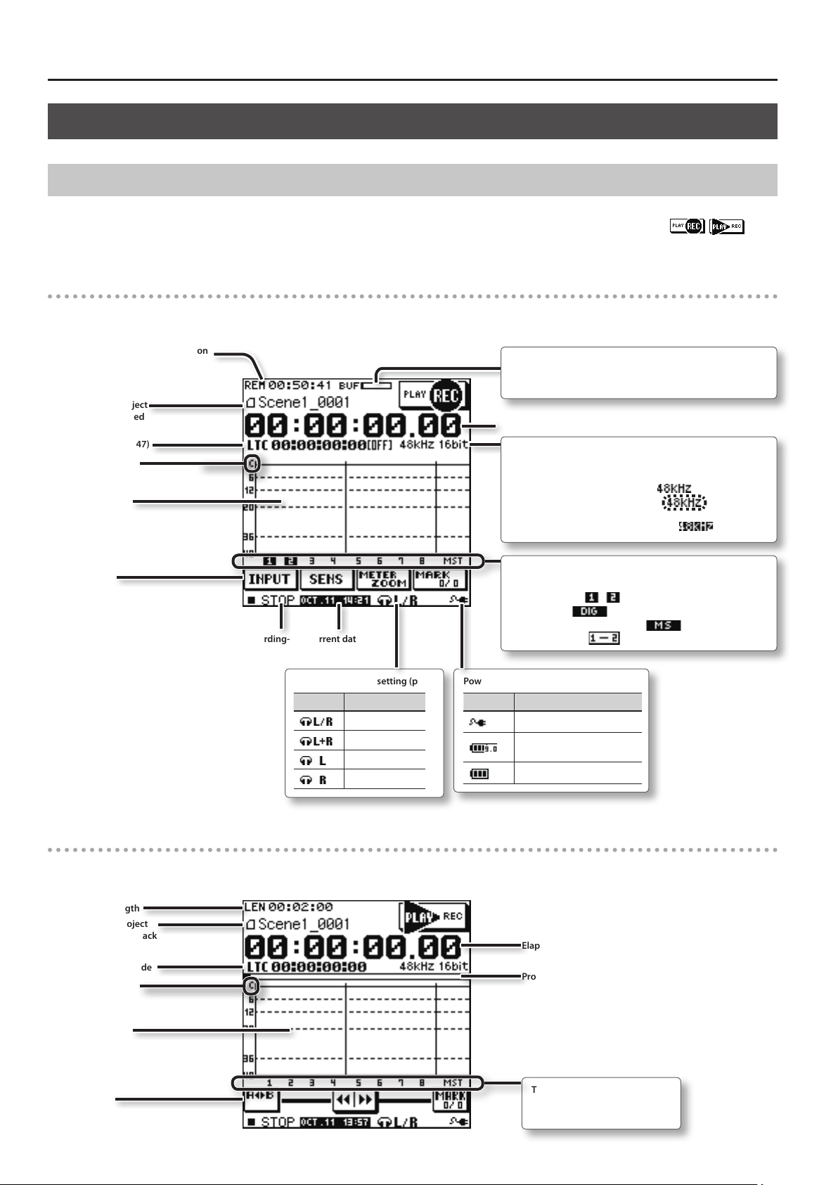
The screen that appears when you turn on the power is called the home screen.
The home screen will switch in tandem with record or playback operations. If you want to switch screens while stopped, touch
upper right of the screen.
Home screen for recording
This is the recording-standby screen. In this state, the audio input can be monitored at all times, and recording can be started at any moment.
in the
Remaining recordable time on
the SD card
* “REM” will blink when the
remaining time runs low.
Name of project
being recorded
Timecode (p. 47)
Clip indicator
Level meter
Buttons
Record/recording-
standby status
Current date and
time
Headphone output setting (p. 34)
Icon Settings
Stereo
L+R MIX mono
L mono
R mono
Buer indicator
Movement of this meter toward the right indicates that it is
taking a longer time to write data to the SD card.
Elapsed recording time of the project
Recording settings
The sampling rate indication will change depending on the
status of DIGITAL IN.
• No digital connection/No signal =
• Abnormal digital signal reception=
(The sampling rate is incorrect)
• Digital signal being received normally=
Track number
The display will change depending on the settings.
• INPUT SW ON =
• DIGITAL IN =
• INPUT MS-MIC DECODER ON =
• INPUT LINK ON =
Power supply status (p. 23)
Icon Power Supply
AC Adaptor
External Power Supply (the
number is the nal voltage)
Battery
(black text)
(blinking)
(highlighted)
Home screen for playback
This is the playback-standby screen. Audio input is muted while this screen is displayed.
Project length
Name of project
being played back
Project timecode
Clip indicator
Level meter
Buttons
10
Elapsed playback time of the project
Progress bar
Track number
The numbers are shown only for
tracks that contain recorded data.
Page 11
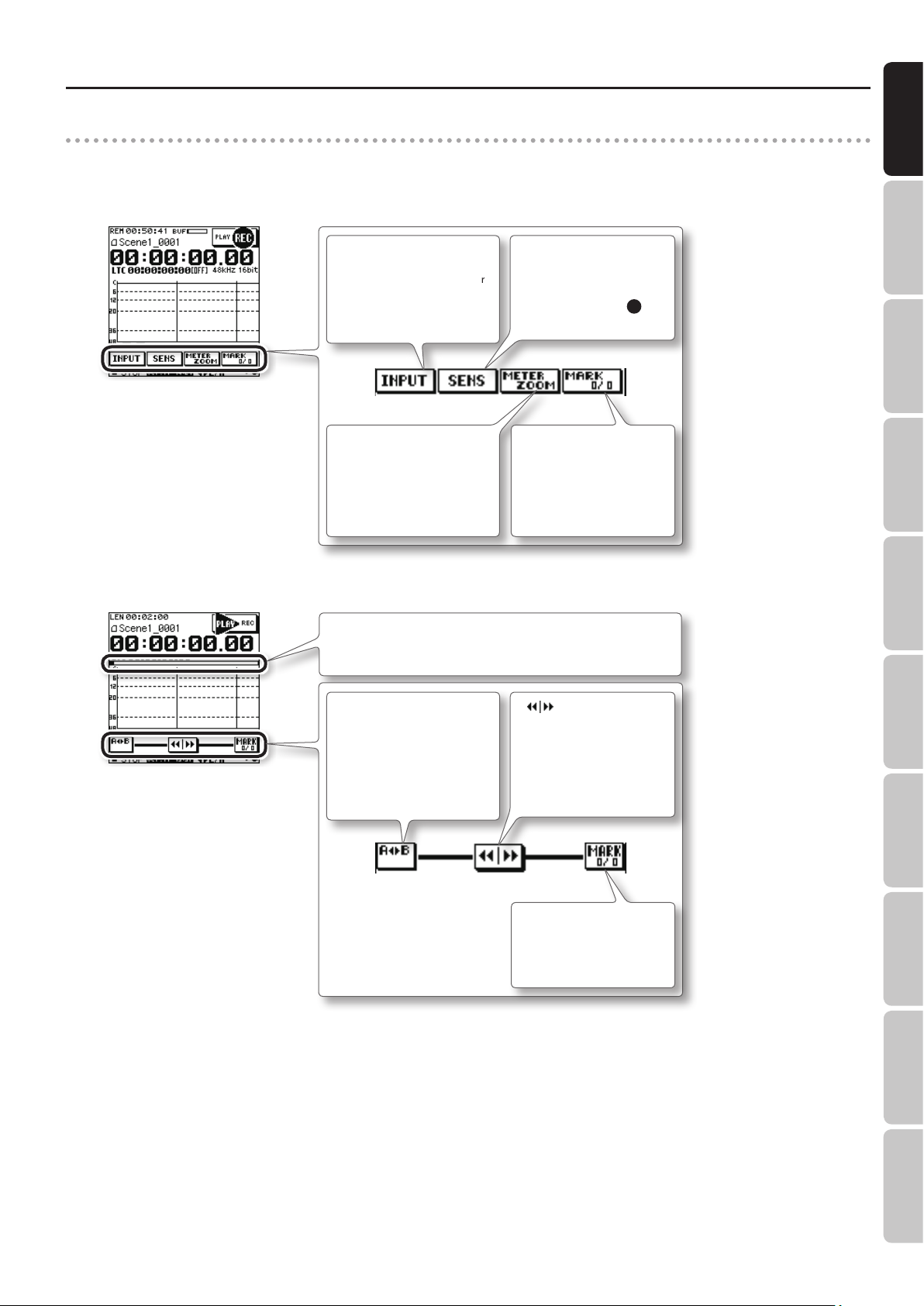
Buttons in the home screen
By touching the buttons in the bottom of the record/stop or playback home screens, you can edit the various input settings, specify how the level
meters will be displayed, and assign markers within the project.
During recording
Overview
Overview Quick Guide Getting Ready IN/OUT/Monitor
During playback
<INPUT> button
Switch each input on/o,
specify low cut, and make limiter
settings (p. 28).
<METER ZOOM> button
Magnies the 20 dB region of the
level meter display.
Progress Bar
Indicated the playback position.
By touching this you can jump to the desired playback position.
<A-B> button
Repeatedly play back the
specied region (AB repeat)
within the project(p. 40).
<SENS> button
Check the sensitivity setting
of each input. The value of the
sensitivity setting is adjusted
using the [SENS] knobs
(p. 6) on the front panel.
<MARK> button (during
recording)
Assigns a marker within the
project (p. 38). By touching this
button during recording, you
can assign a marker to the
current location.
< > button
By touching and sliding this
button to the left or right, you
can rewind or fast-forward the
project. Rewind or fast-forward
will become faster as you move
the button farther from the
center.
13
Recording/Playback
Mixer Timecode File Operation USB Appendix
<MARK> button
Touch this button to access the
Marker screen (p. 38).
11
Page 12
Overview
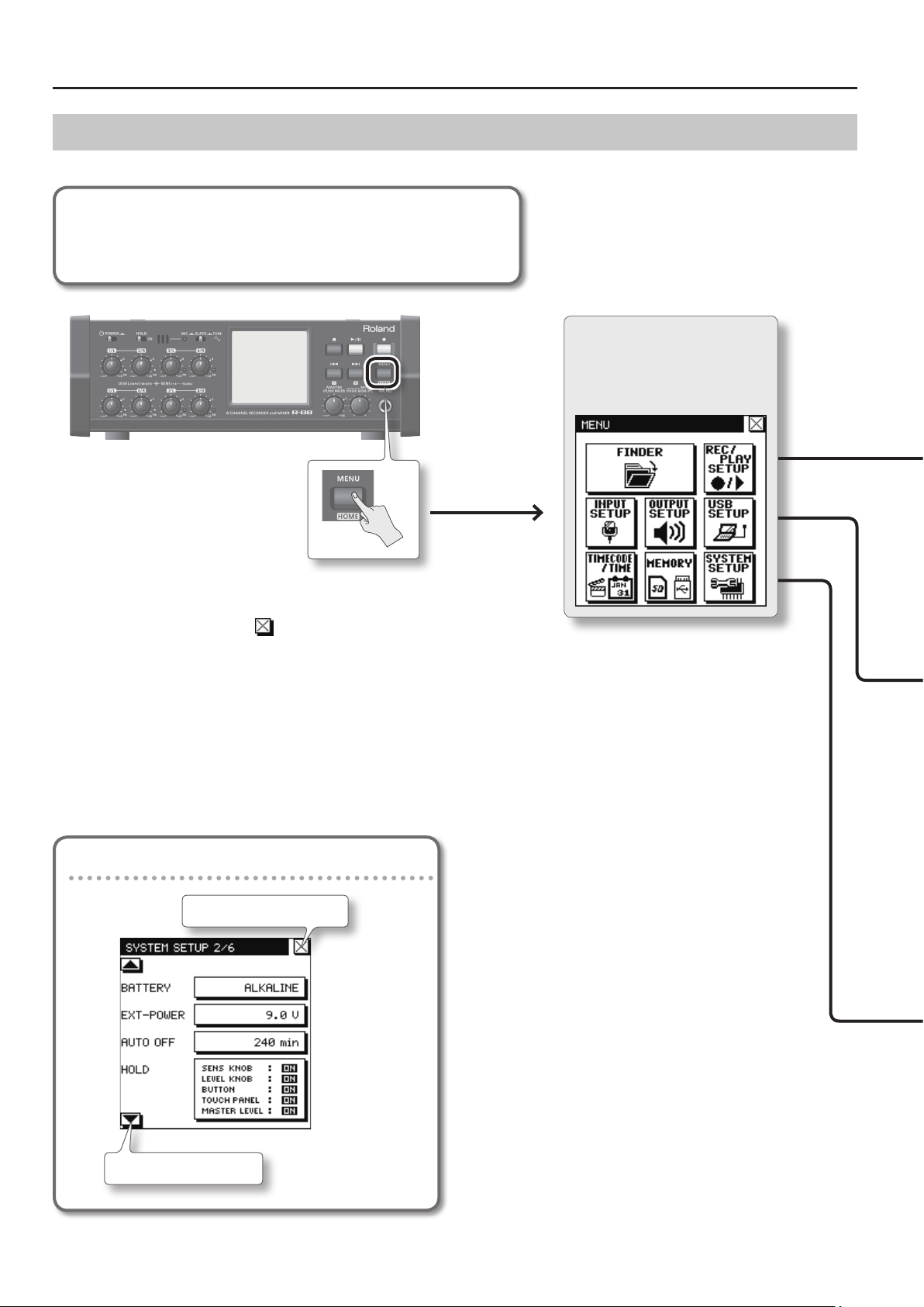
MENU Screen
This screen will appear when you press the [MENU] (HOME) button.
In this manual, operations starting from the MENU screen are expressed as follows.
<Example>
Select <REC/PLAY SETUP>, and then select <REC FILE>.
[MENU]Ú<REC/PLAY SETUP>Ú<REC FILE>
MENU
This is the main menu screen.
To return to the previous screen, press
the [MENU] (HOME) button once again,
or touch
* By pressing the [MENU] (HOME) button you
can instantly return to the home screen from
any level.
in the screen.
Basic Operation of each screen
Go back to the previous screen
Touch one of these icons to access the corresponding
setting screen.
Go to the next page
The explanations in this manual include illustrations that depict what should typically be shown by the display. Note, however, that your unit may
incorporate a newer, enhanced version of the system, so what you actually see in the display may not always match what appears in the manual.
12
Page 13
Overview
Overview Quick Guide Getting Ready IN/OUT/Monitor
• For details on each screen, refer to the pages listed on
• For details of each parameter, refer to “Parameter List” (p. 65).
FINDER
Manage projects and folders.
INPUT SETUP
Make input settings.
p. 51
p. 28
P. XX
.
OUTPUT SETUP
Make output settings.
p. 32
REC/PLAY SETUP
p. 35, p. 39
Make recording and playback settings.
USB SETUP
Make settings for using the R-88 as a USB
audio interface.
p. 60, p. 63
Recording/Playback
TIMECODE/TIME MENU
p. 47, p. 26
Make settings for the timecode, date,
and time.
MEMORY MENU
p. 58, p. 27
Make settings for SD cards and USB ash
drives.
SYSTEM SETUP
Make settings for the R-88 itself.
p. 66
Mixer Timecode File Operation USB Appendix
13
Page 14
Overview
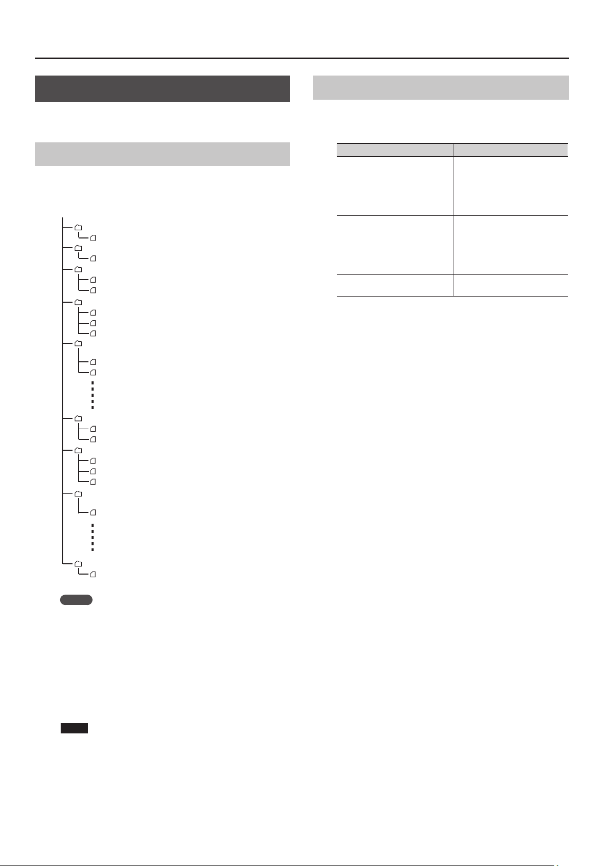
What Is a Project?
On the R-88, the data that you record and play back are handled in
units called “projects.”
Project File Structure
If you connect the R-88 to your computer, you can see how these
folders and les are organized (p. 61).
/Root
R88_0001.PJT
R88_0001_1.WAV
R88_0002.PJT
R88_0002_1.WAV
R88_0003.PJT
R88_0003_1.WAV
R88_0003_2.WAV
R88_0004.PJT
R88_0004_1.WAV
R88_0004_2.WAV
R88_0004_3.WAV
R88_0004_M.PJT
R88_0004_M_L.WAV
R88_0004_M_R.WAV
(Monaural 1-channel project)
(Monaural WAV)
(Stereo 1-channel project)
(Stereo WAV)
(Monaural 2-channel project)
(Monaural WAV)
(Monaural WAV)
(Monaural 3-channel project)
(Monaural WAV)
(Monaural WAV)
(Monaural WAV)
(Monaural 2-channel project created by
making a 2-channel mix of R88_0004.PJT)
(Monaural WAV)
(Monaural WAV)
BWF and iMXL
The WAV les recorded by the R-88 are in BWF (Broadcast Wave
Format). The recording start time and the following iXML metadata
will be included in the le.
iXML metadata Explanation
This will record the date if the
PROJECT NAME setting (p. 35) is
<SCENE>
<TAKE>
<SPEED><TIMECODE_RATE>
<SPEED><TIMECODE_FLAG>
* The iXML metadata is not loaded at the time of playback.
“Date”, or the specied text string if
the setting is “U1–U8.”
If you edit the project name, this
data will also be changed.
This will record the time if the
PROJECT NAME setting (p. 35) is
“Date”, or a sequential number if the
setting is “U1–U8.”
If you edit the project name, this
data will also be changed.
This records the TIMECODE RATE.
R88_0005.PJT
R88_0005_1.WAV
R88_0005_2.WAV
R88_0006.PJT
R88_0006_1.WAV
R88_0006_2.WAV
R88_0006_3.WAV
R88_0006_M.PJT
R88_0006_M_0.WAV
SETUP
SETUP.TXT
(Stereo 2-channel project)
(Stereo WAV)
(Stereo WAV)
(Stereo 3-channel project)
(Stereo WAV)
(Stereo WAV)
(Stereo WAV)
(Stereo 1-channel project created by
making a 2-channel mix of R88_0006.PJT)
(Stereo WAV)
Backup of the R-88’s settings (p. 58)
MEMO
If MIX REC (p. 35) is ON, a stereo two-channel mix project will be
recorded simultaneously with the multitrack project.
For example, if you’re recording a multitrack project named
“R88_0004.PJT,” a 2-channel mix project named “R88_0004_M.
PJT” will be recorded at the same time.
The 2-channel mix project will be saved with the le names
R88_0001_M_L.WAV and R88_0001_M_R.WAV when recording
in monaural, or the le name R88_0001_M_0.WAV when
recording in stereo.
14
NOTE
If you use your computer to modify, delete, or rename the
les within a project, the R-88 may be unable to play back the
project.
Page 15
1
This Quick Guide explains basic operation.
For details, refer to the pages shown by the
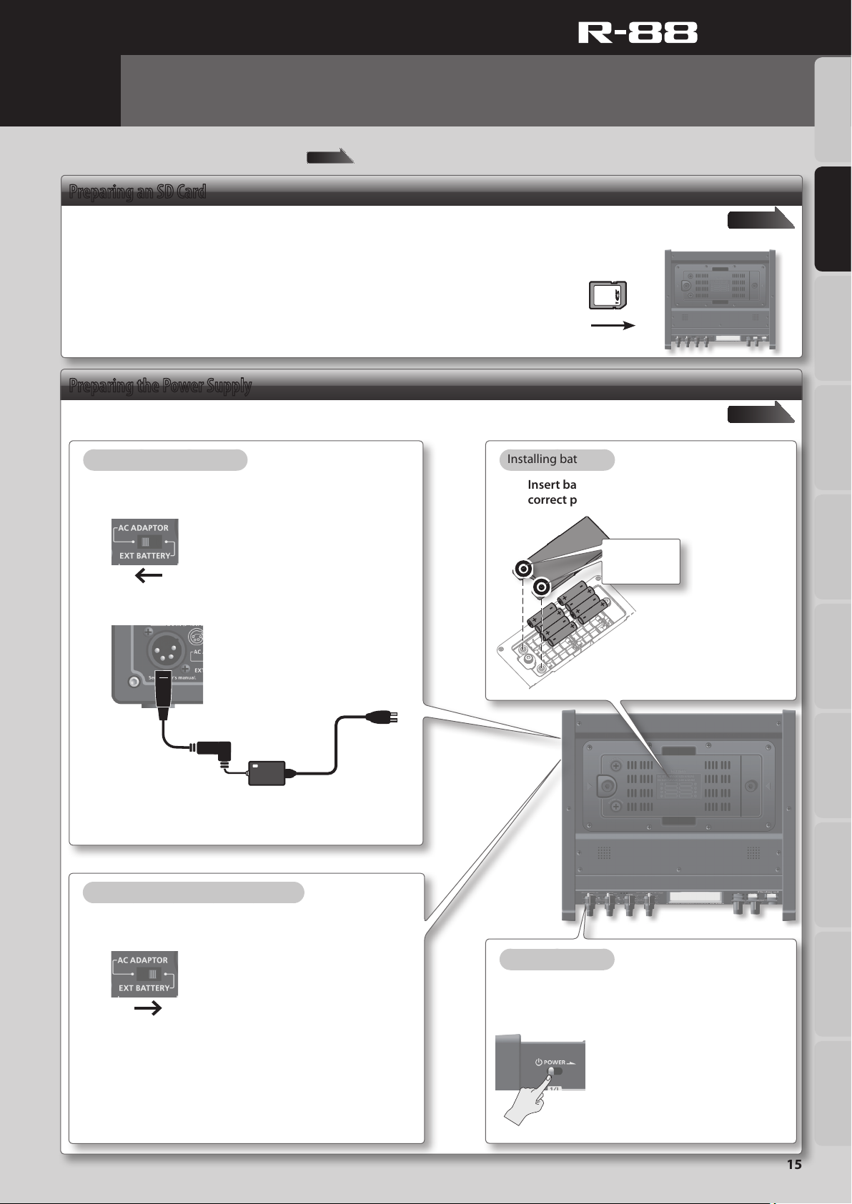
Getting Ready
Preparing an SD Card
page XX
Quick Guide
Overview Quick Guide Getting Ready IN/OUT/Monitor
symbol.
Insert a commercially available SD card.
1. Open the rubber ap located on the left side panel.
* The cover may break if you use excessive force.
2. Insert the SD Card.
Preparing the Power Supply
Prepare batteries, an external power supply, or the AC adaptor.
Connecting the AC adaptor.
1. On the side panel (left), set the external power supply
select switch to “AC ADAPTOR.”
2. Connect the AC adaptor.
Label facing
upward
Installing batteries
Insert batteries, taking care to observe the
correct polarity.
Loosen these
two screws.
page 26
page 23
Recording/Playback
Connecting the external power supply
1. On the side panel (left), set the external power supply
select switch to “EXT BATTERY.”
2. Connect the cable of a commercially available external
power supply to the DC IN jack.
3. Specify the nal voltage.
* For details on making this setting, refer to “Using External
Power Sources” (p. 24).
Mixer Timecode File Operation USB Appendix
Turn on the power
Slide the [POWER] switch on the front panel in
the direction of the arrow, and hold it there for
several seconds.
15
Page 16
Quick Guide
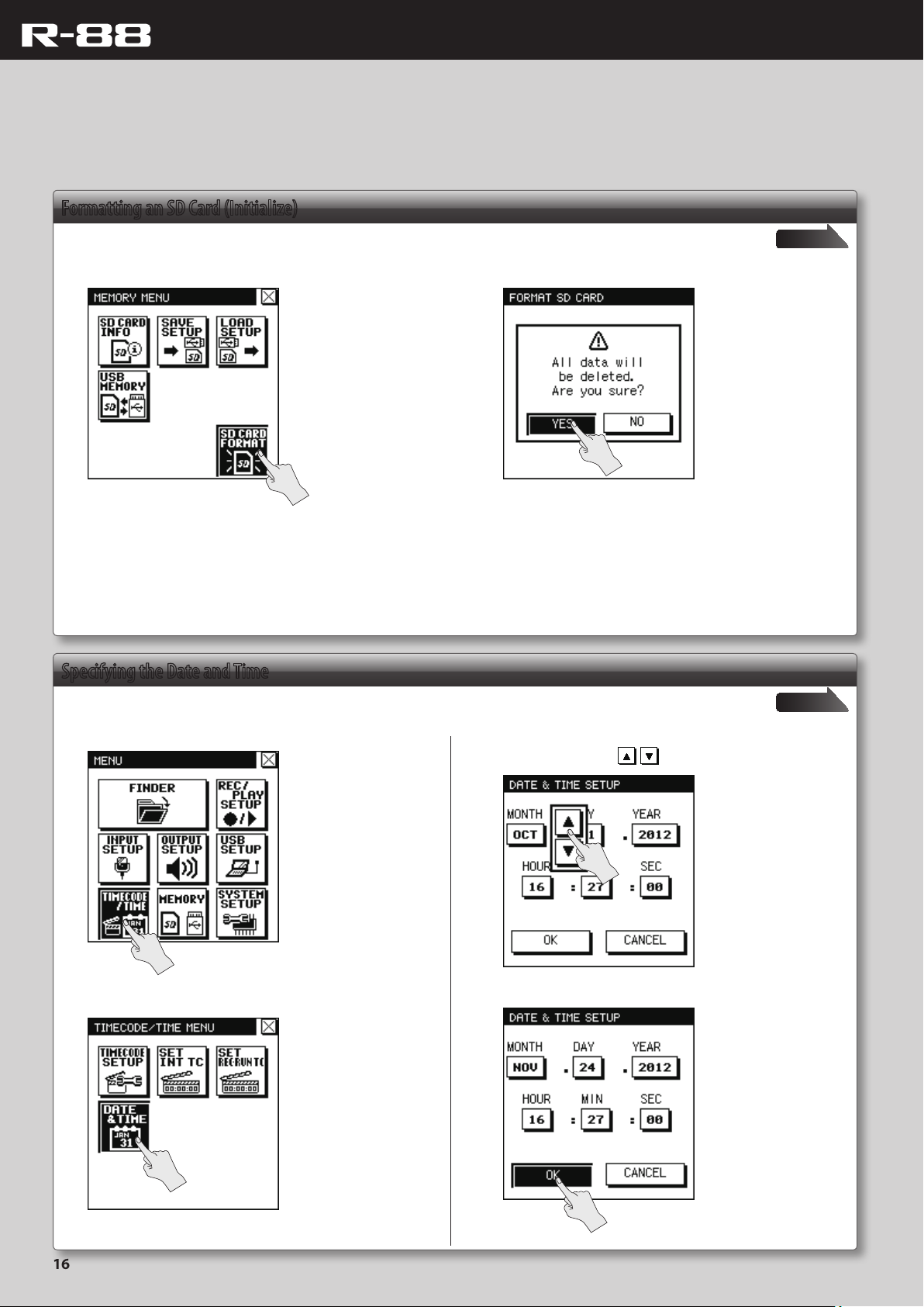
Formatting an SD Card (Initialize)
Before using an SD card for the rst time, you must rst format (initialize) the SD card.
1. Choose [MENU]Ú<MEMORY>Ú<SD CARD FORMAT>. 2. Touch <YES>.
Formatting will begin. When formatting is nished, the display will
indicate “COMPLETED!.”
Specifying the Date and Time
page 27
Here’s how to set the date and time of the R-88’s internal clock.
1. Choose [MENU]Ú<TIMECODE/TIME>.
2. Touch <DATE & TIME>.
page 26
3. Specify the date and time.
Touch each item, and use to set the date and time.
4. Touch <OK> to conrm the setting.
16
Page 17
Quick Guide
2
This section explains the basic settings for recording, and the procedures for recording and playback.
Recording
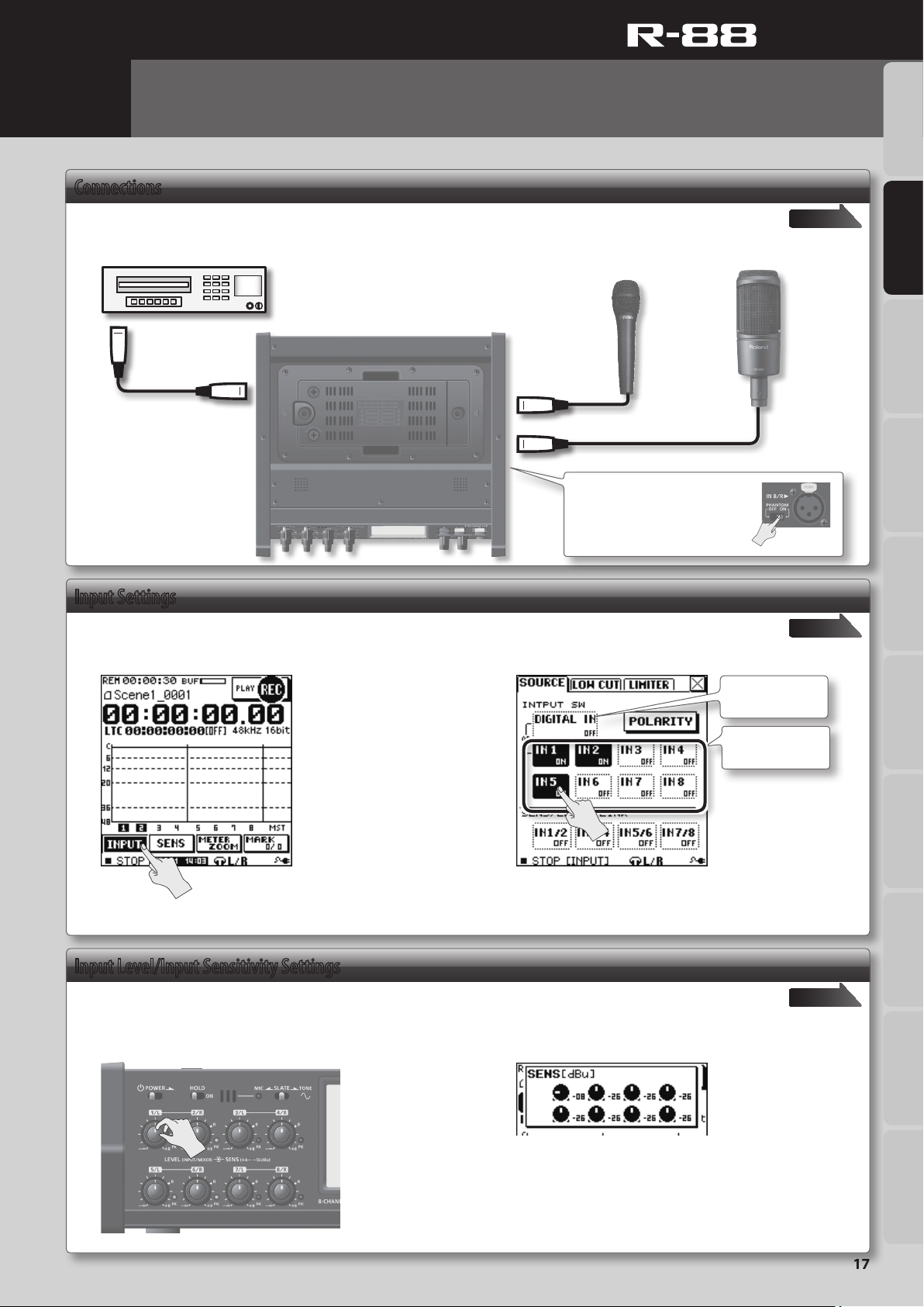
Connections
Connect your recording mics or recording sources to the R-88’s input jacks.
CD player or other audio source
Equipment that has
a digital output jack
(XLR)
DIGITAL IN
IN 1/L–IN 8/R
Dynamic Mic Condenser Mic
Setting of the Phantom Power
Set the [PHANTOM] switch (p. 8) to
“ON” when you have connected a
condenser microphones that require
phantom power.
Overview Quick Guide Getting Ready IN/OUT/Monitor
page 28
Recording/Playback
Input Settings
Turn on the inputs that you want to record. Recording is possible only for inputs that are turned on.
1. In the home screen (recording) (p. 10), touch <INPUT>.
* You can also access the input
setup screens by pressing
[MENU]
Ú<INPUT SETUP>.
2. Touch the icon for each input to turn it on/o.
Input Level/Input Sensitivity Settings
Adjust the sensitivity and input level for each input to be recorded.
Use the [LEVEL]/[SENS] knobs to adjust the level and
sensitivity.
When you move a [SENS] knob (outer), the current value is shown
in the screen.
page 28
Input from the
DIGITAL IN jack
Input from the IN
1/L–IN 8/R jacks
* DIGITAL IN cannot be used
simultaneously with IN 1
and IN 2.
page 31
Mixer Timecode File Operation USB Appendix
For details on adjusting the input level, refer to “Adjusting the
input level” (p. 31).
* The level cannot be adjusted for DIGITAL IN.
17
Page 18
Quick Guide
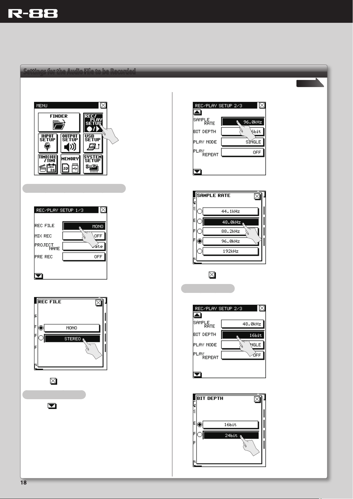
Settings for the Audio File to be Recorded
Choose the type of audio le to be recorded (mono/stereo), and choose the sampling rate and bit depth.
1. Choose [MENU]Ú<REC/PLAY SETUP>.
Choose the type of audio le (stereo/mono)
6. Touch the <SAMPLE RATE> item.
7. Touch the rate that you want to use.
2. Touch the <REC FILE> item.
page 35
3. Touch the type that you want to set.
4. Touch to close the <REC FILE> window.
Choose the sampling rate
5. Press so that 2/3 is displayed.
8. Touch to close the <SAMPLE RATE> window.
Choose the bit depth
9. Touch the <BIT DEPTH> item.
10. Touch the bit depth that you want to use.
18
Page 19
Quick Guide
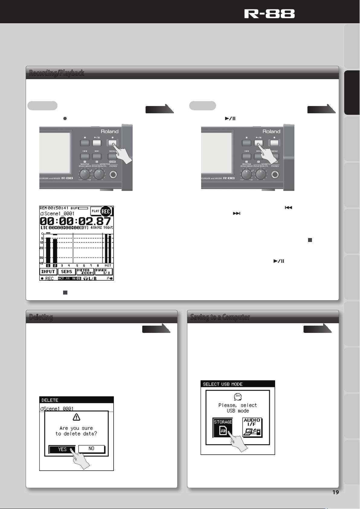
Recording/Playback
Recording will take place using the input settings and audio le settings you made on p. 17 and p. 18. You can then play back the recorded le.
Overview Quick Guide Getting Ready IN/OUT/Monitor
Recording
1. Press the [ ] (REC) button.
The button will light, and recording will begin.
page 37 page 39
Playback
1. Press the [ ] button.
The recorded project will begin playing back.
During playback, you can hold down the [
hold down the [ ] button to fast-forward. When you release the
respective button, playback will resume.
When playback reaches the end of the project, it will stop. If you
want to stop before the end of the project, press the [
button.
During playback, you can press the [
playback. When you press the button once again, playback will
resume from the location at which you paused.
] button to rewind, or
] (STOP)
] button to pause
Recording/Playback
Mixer Timecode File Operation USB Appendix
2. Press the [ ] (STOP) button to stop recording.
Deleting
Here’s how to delete a recorded project.
page 53
1. Choose [MENU]Ú<FINDER>.
2. Touch the name of the project or folder that you want to
delete.
The recorded project will blink.
3. Touch <DELETE>.
4. Touch <YES>.
Saving to a Computer
Here’s how to save a recorded project to your
computer.
page 61
1. Start up your computer.
2. Use a commercially available USB cable to connect the
R-88 to your computer.
3. Touch <STORAGE>.
* Only if you’ve selected “SELECTABLE”
4. On your computer, copy the desired le(s) from the SD
card.
19
Page 20
Quick Guide
3
The R-88 allows you to create a two-channel stereo mix of the audio from the IN 1–IN 8 and DIGITAL IN inputs during recording, or from the audio of the
tracks of a previously recorded project. This section explains basic operation of the mixer functionality.
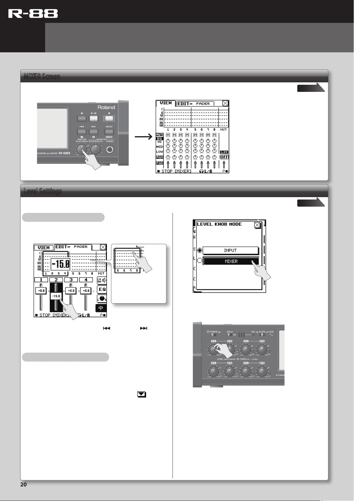
Mixer
MIXER Screen
Press the [MASTER] knob on the front panel.
Level Settings
Here’s how to adjust the input levels during recording, or the levels of each track during playback.
Adjustment using the touch panel
2. Touch <MIXER>.
page 43
page 43
1. Touch a slider to display EDIT–FADER screen.
2. Touch a slider and drag it up or down.
To see the CH. 5–CH. 8
settings, touch the area on
the level meter to switch the
display.
To make ne adjustments, use the [ ] (−) button or [ ] (+)
button (p. 43).
3. Touch the <VIEW> tab to return to the VIEW screen.
Adjustment using the [LEVEL] knobs
You can also adjust the levels by using the [LEVEL] knobs (1/L–8/R)
on the front panel.
1. Choose [MENU]Ú<SYSTEM SETUP>Ú<LEVEL KNOB
MODE>.
<LEVEL KNOB MODE> is located on page 3/6. Touch to access
3/6.
* If the LEVEL KNOB mode is set to MIXER, the INPUT LEVEL is
xed at 0 dB.
3. Use the [LEVEL] knobs to adjust the level.
* If the LEVEL KNOB MODE is set to MIXER, you can’t use the on-
screen sliders to adjust the level.
20
Page 21
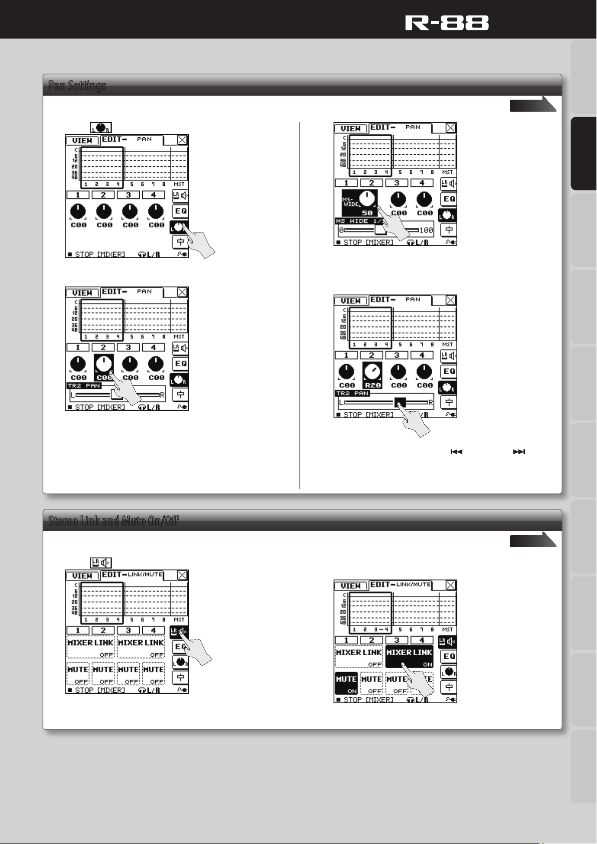
Pan Settings
Quick Guide
Overview Quick Guide Getting Ready IN/OUT/Monitor
Here’s how to adjust each input’s pan during recording, or the pan of each track during playback.
1. Touch to access the pan adjustment screen.
This will adjust “MS-MIC WIDE” on channels for which the MS mic
decoder (p. 41) is on.
2. Touch the knob that you want to adjust.
3. Drag the slider to the left or right to adjust the pan.
page 44
Recording/Playback
A slider will appear in the bottom of the screen.
Stereo Link and Mute On/O
Here’s how to turn stereo link (p. 45) and mute (p. 44) on/o.
1. Touch .
To make ne adjustments, use the [ ] (−) button or [ ] (+)
button (p. 44).
page 44
2. Touch <MIXER LINK> or <MUTE> for the channel whose
setting you want to turn on/o.
Mixer Timecode File Operation USB Appendix
21
Page 22
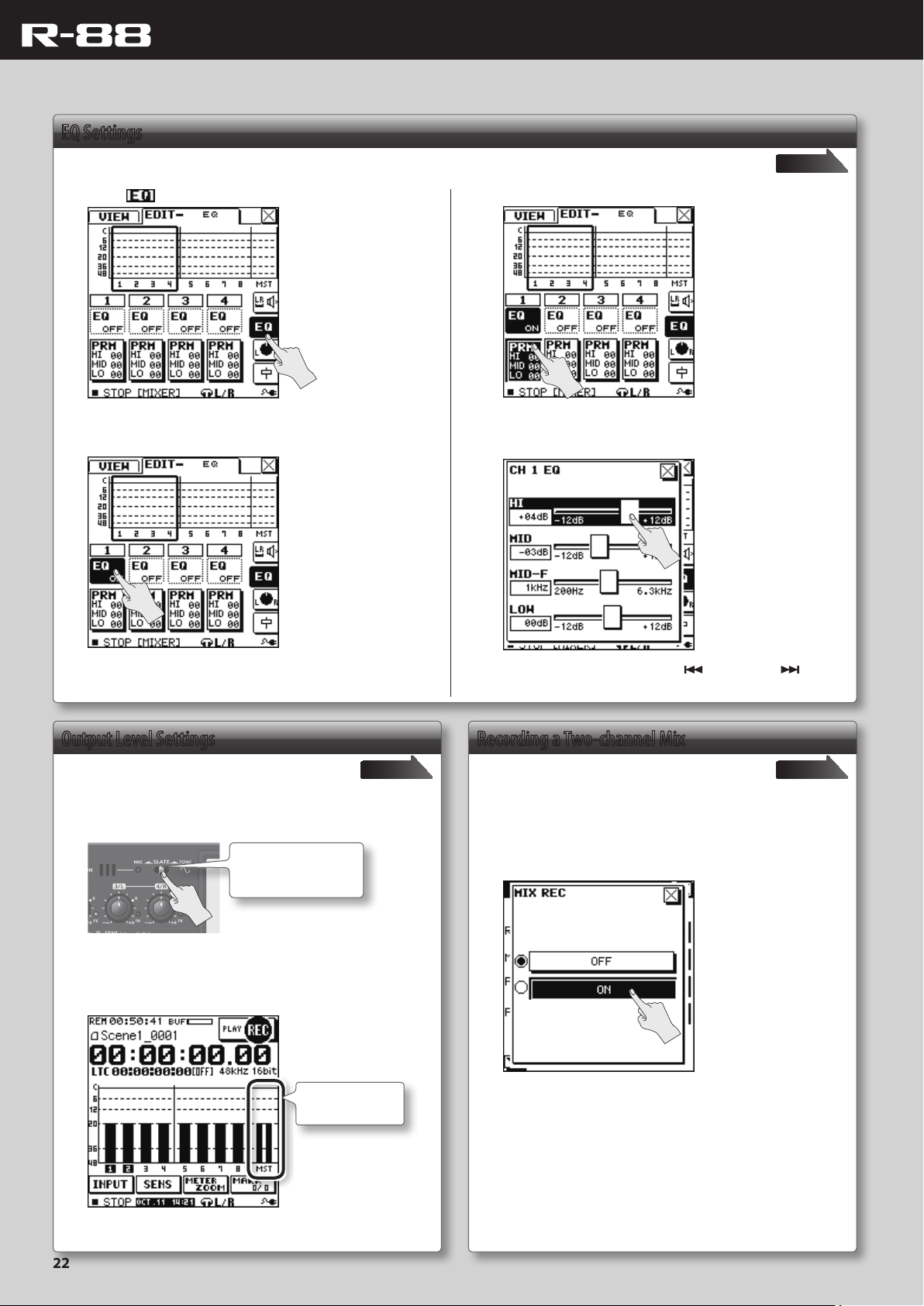
EQ Settings
Quick Guide
Here’s how to make EQ settings.
1. Touch .
2. Touch <EQ> of the channel whose setting you want to
turn on/o.
page 45
3. Touch <PRM>.
4. Touch the slider for a parameter, and drag it left or right
to adjust its value.
Output Level Settings
Here’s how to adjust the output level to achieve the
appropriate level when the R-88 is connected to an
external device.
page p. 46
1. Activate the slate tone (p. 50).
Slide the switch to the
TONE position and hold
it there for two seconds.
* The slate tone cannot be output when the home screen is in
playback mode.
2. Adjust the [MASTER LEVEL] knob so that the MASTER
LEVEL meter (MST) is at the appropriate level.
MASTER LEVEL
Meter
To make ne adjustments, use the [ ] (−) button or [ ] (+)
button (p. 45).
Recording a Two-channel Mix
You can record a separate two-channel stereo mix
project simultaneously while recording a multitrack
project.
page 35
1. Choose [MENU]Ú<REC/PLAY SETUP>Ú<MIX REC>.
2. Touch <ON>.
3. Make the appropriate adjustments to the input level of
the connected device.
22
Page 23
Setup
Overview Quick Guide Getting Ready IN/OUT/Monitor
Preparing the Power Supply
The R-88 can operate using an AC adaptor, batteries, or an external
power device.
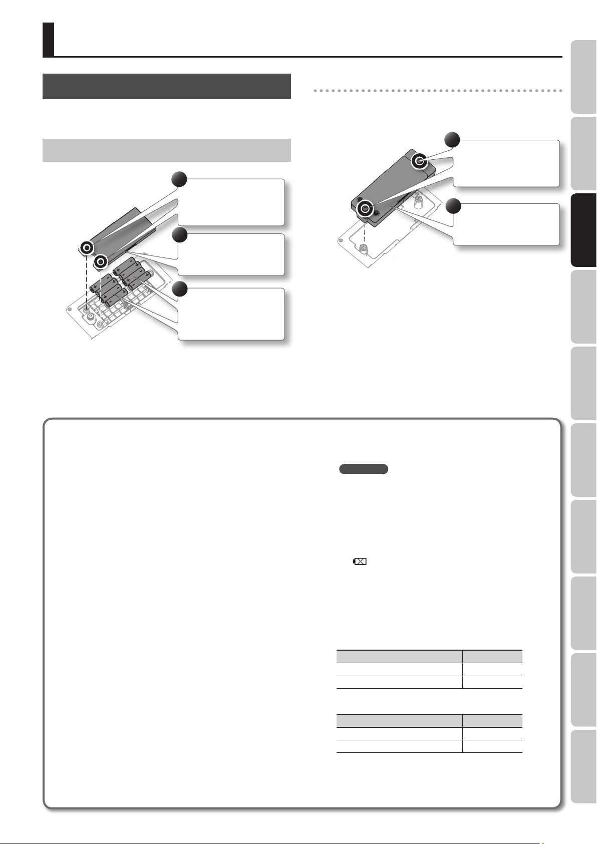
Installing Batteries
1
Loosen the screws
from these two
locations.
2
Remove the battery
compartment cover.
3
Insert batteries,
taking care to observe
the correct polarity.
* We recommend that you keep batteries installed in the unit
even though you’ll be powering it with the AC adaptor. That
way, you’ll be able to continue a performance even if the cord of
the AC adaptor gets accidently disconnected from the unit.
* If operating this unit on batteries, please use alkaline batteries,
rechargeable Ni-MH batteries.
Removing the battery case
Although it is possible to replace the batteries without removing
the battery case, battery replacement will be easier if you remove
the battery case.
1
Loosen the screws
from these two
locations.
2
Remove the battery
case.
Recording/Playback
Note when using the R-88 on batteries
If used improperly, batteries may explode or leak and cause
damage or injury. In the interest of safety, please read and
observe the following precautions.
• Carefully follow the installation instructions for batteries, and
make sure you observe the correct polarity.
• Avoid using new batteries together with used ones. In
addition, avoid mixing dierent types of batteries.
• Remove the batteries whenever the unit is to remain unused
for an extended period of time.
• Never keep batteries together with metallic objects such as
ballpoint pens, necklaces, hairpins, etc.
• Incorrect handling of batteries, rechargeable batteries, or
a battery charger can cause leakage, overheating, re, or
explosion. Before use, you must read and strictly observe
all of the precautions that accompany the batteries,
rechargeable batteries, or battery charger.
• When using rechargeable batteries and a charger, use only
the combination of rechargeable batteries and charger
specied by the battery manufacturer.
Types of batteries that can be used
• AA alkaline batteries (LR6)
• AA rechargeable Ni-MH batteries (HR6)
Choose <MENU>Ú<SYSTEM SETUP>Ú<BATTERY>(p. 66), and
specify the battery that you’re using.
* The R-88 cannot recharge rechargeable Ni-MH batteries.
You’ll need to use a battery charger designed for
rechargeable Ni-MH batteries.
certain period of time without performing any operation, the
display will dim or the unit’s power will turn o, depending on
the power conservation setting.
REFERENCE
“Parameter List” (p. 65)
* To prevent the power from turning o automatically, Choose
[MENU]Ú<SYSTEM SETUP> and turn the AUTO OFF setting
OFF. For details, refer to ”Turning the Power On/O” (p. 25).
Remaining battery indication
When the remaining battery power runs low, a battery low
icon appears in the lower right of the display. When
this appears, install fresh batteries as soon as possible. If
you continue to use the unit in this state, the display will
indicate“Battery Low,” and nally the R-88 will stop functioning
entirely.
Expected battery life under continuous use:
• 96 kHz, 8 channel, phantom power on with total of 40 mA
Type of battery Battery life
Alkaline battery (AA, LR6) Approx. 1 hours
Rechargeable Ni-MH battery (AA, HR6) Approx. 2 hours
• 96 kHz, 2 channel, phantom power o
Type of battery Battery life
Alkaline battery (AA, LR6) Approx. 3 hours
Rechargeable Ni-MH battery (AA, HR6) Approx. 4 hours
Mixer Timecode File Operation USB Appendix
Power conservation function
The R-88 has a power conservation function, which prevents
unnecessary battery consumption. If you leave the unit for a
* These gures will vary depending on the specications of
the batteries and the actual conditions of use.
23
Page 24
Setup
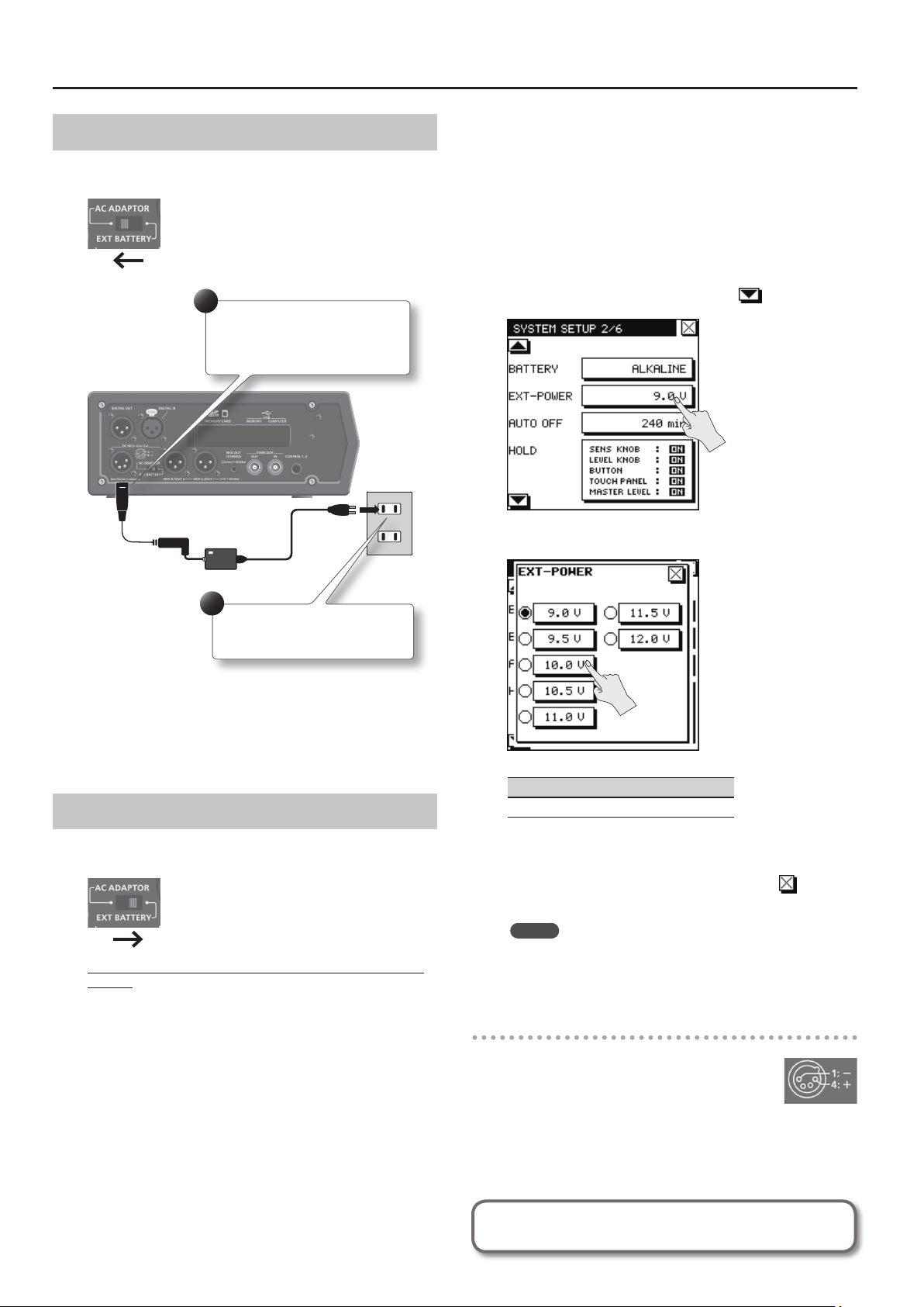
Connecting the AC adaptor
If you are using an AC adaptor, you must set the external power
supply select switch to “AC ADAPTOR.”
1
Connect the plug of the AC
adaptor to the R-88’s DC IN
jack.
* When using an external power source, even when power is
automatically cut o, the R-88 starts within 30 seconds after
power is turned back on. During this period, the nal voltage
settings can be changed.
* Read the following to set the nal voltage for the R-88.
Setting the nal voltage
1.
Choose [MENU]Ú<SYSTEM SETUP>.
2. Touch <EXT POWER>.
<EXT POWER> is located on page 2/6. Touch to access 2/6.
2
Plug the AC adaptor into an
AC power outlet.
* Place the AC adaptor so the side with the indicator (see
illustration) faces upwards and the side with textual information
faces downwards.
The indicator will light when you plug the AC adaptor into an
AC outlet.
* Be sure to use the AC adaptor included with this product.
Using External Power Sources
If you are using an external power supply, you must set the external
power supply select switch to “EXT BATTERY.”
When using an external power supply, be sure to set the nal
voltage.
The nal voltage refers to the voltage when voltage can no longer
be supplied because the capacity of the external power source is
reduced and voltage decreases as electricity is consumed.
If the nal voltage is not properly set for the external power source,
the remaining power display cannot be shown. Refer to the user’s
manual of the external power supply for the nal voltage value.
Furthermore, when the “Battery Low” message is displayed, the
recording automatically stops, and the power automatically turns
o. Change the external power source.
3. Touch the nal voltage value that you want to specify.
Setting
9.0 V, 9.5 V, 10.0 V, 10.5 V, 11.0 V, 11.5 V, 12.0 V
4. Press the [MENU] (HOME) button to return to the home
screen.
You can also return to the home screen by touching a number
of times.
MEMO
If an external power source is connected, the R-88 will not
switch to battery operation even if the voltage of the external
power source drops below the nal voltage.
DC IN jack pin conguration
Make sure that the wiring of your external
power source matches the R-88’s power supply
connector. Be aware that malfunctions will occur
if you connect an external power source that is
wired dierently.
24
Refer to the user’s manual for the external power source when using an
external power source.
Page 25

Turning the Power On/O
* Once everything is properly connected (p. 28, p. 32), be sure to
follow the procedure below to turn on their power. If you turn
on equipment in the wrong order, you risk causing malfunction
or equipment failure.
Slide the [POWER] switch in the
direction of the arrow and hold
it there for several seconds to
turn the power on/o.
When you turn on the power, the start-up screen will appear in the
display, and then the home screen will appear.
Setup
Overview Quick Guide Getting Ready IN/OUT/Monitor
Preventing the Power from
Automatically Turning O (AUTO OFF)
The power to this unit will be turned o automatically
after a predetermined amount of time has passed since its
buttons or controls were last operated (AUTO OFF function).
If you do not want the power to be turned o automatically,
disengage the AUTO OFF function as follows.
1. Choose [MENU]Ú<SYSTEM SETUP>Ú<AUTO OFF>.
<AUTO OFF> is located on page 2/6. Touch to access
2/6.
* This unit is equipped with a protection circuit. A brief interval (a
few seconds) after turning the unit on is required before it will
operate normally.
* Before turning the unit on/o, always be sure to turn the volume
down. Even with the volume turned down, you might hear some
sound when switching the unit on/o. However, this is normal
and does not indicate a malfunction.
Recording/Playback
2. Touch <OFF>.
Mixer Timecode File Operation USB Appendix
NOTE
• Any settings that you are in the process of editing will be
lost when the power is turned o. If you have any settings
that you want to keep, you should save them beforehand.
• To restore power, turn the power on again.
25
Page 26

Setup
Setting the Date and Time
1. Choose [MENU]Ú<TIMECODE/TIME>.
2. Touch <DATE & TIME>.
The calendar and clock setting screen will appear.
Date
Time
3. Specify the date and time.
Touch each item, and use to set the date and time.
SD Card
The R-88 stores recorded data on the SD card.
Inserting an SD Card
1. Make sure that the power is o.
2. Open the Rubber ap located on the left side panel.
* The cover may break if you use excessive force.
3. Insert the SD card.
With the label surface of the SD card facing upward, insert it gently.
Label facing
upward
4. When you’ve nished setting all items, touch <OK>.
By touching <CANCEL> you can return to the previous screen
without making settings.
5. Press the [MENU] (HOME) button to return to the home
screen.
You can also return to the home screen by touching a number
of times.
NOTE
• Forcibly inserting the SD card in the wrong orientation may
damage the R-88 or the SD card. Please use caution.
• Press the SD card rmly all the way in.
4. Close the Rubber ap.
5. Switch on the power (p. 25).
MEMO
If an unformatted SD card is inserted in the R-88, the screen will
indicate “SD Unformatted.”
26
Page 27

Formatting an SD Card
If the SD card is being used for the rst time, you must format the
card before it can be used.
NOTE
• When you format an SD card, all data on the card will be erased.
If the card contains important data, back it up to your computer
rst.
• You must format the SD card on the R-88 itself. An SD card
formatted on a device other than the R-88 might not work
correctly in the R-88.
1. Make sure that the SD card you want to format is inserted
in the SD card slot.
2. Choose [MENU]Ú<MEMORY>.
3. Touch <SD CARD FORMAT>.
Setup
Overview Quick Guide Getting Ready IN/OUT/Monitor
The card will be formatted.
When formatting has been completed, the following screen will
appear.
4. To format the card, touch <YES>.
5. Press the [MENU] (HOME) button to return to the home
screen.
You can also return to the home screen by touching a number
of times.
Removing an SD Card
1. Switch o the R-88’s power (p. 25).
2. Open the Rubber ap.
3. Gently press the SD card inward, and then release your
nger.
When the SD card pops out, remove it.
NOTE
Do not insert or remove an SD card while the power is on. The data
on the SD card may be lost if you do so.
Recording/Playback
Mixer Timecode File Operation USB Appendix
About SD cards
• The R-88 supports SDHC cards.
• Never insert or remove an SD card/SDHC card while this unit’s power is on. Doing so may corrupt the unit’s data or the data on the SD card/
SDHC card.
• Some memory card types or memory cards from some manufacturers may not record or play back properly on the R-88.
• Carefully insert the SD card/SDHC card all the way in—until it is rmly in place.
The SD card write protect feature (LOCK)
The contents of the SD card/SDHC card can be protected by write protecting it. To write protect a card, slide the write
protect switch on the side of the SD card/SDHC card to the “LOCK” position. Unlock write protect to delete data on the
card.
Write protect switch
27
Page 28

Input Settings
The R-88’s right side panel provides eight analog XLR input jacks, while its left side panel provides one digital input jack; you can record from up to
eight inputs simultaneously.
Connections
CD player or other audio source
Dynamic Mic Condenser Mic
Equipment that has
a digital output jack
(XLR)
DIGITAL IN
IN 1/L–IN 8/R
* To prevent malfunction and equipment failure, always turn down the
volume, and turn o all the units before making any connections.
* When connection cables with resistors are used, the volume level
of the connected equipment may be low. If this happens, use
connection cables that do not contain resistors.
Input Settings
From the home screen (recording), use the <INPUT> (p. 11) to access
the input setting screens.
* You can also access the input setup screens by pressing [MENU]
Ú<INPUT SETUP>.
Input Source Settings
You can turn each input on/o or switch its polarity.
You can also turn linking on/o for the IN 1/2, IN 3/4, IN 5/6, and IN
7/8 input levels and sensitivity.
Input on/o settings
1. From the Home screen, choose <INPUT>.
2. Touch the icon for each input to turn it on/o.
Turn on the inputs that you want to use for recording, and turn o
the other inputs.
Switching the polarity
1. Touch <POLARITY>.
2. Touch the inputs whose polarity you want to invert.
* If the sampling rate (p. 36) is 192 kHz, only IN 1–IN 4 can be used.
28
“INVERT” will be shown on the icon for an input when its polarity is
inverted.
Page 29

Input Settings
Overview Quick Guide Getting Ready IN/OUT/Monitor
Input level and sensitivity link on/o
The input level and sensitivity settings can be linked for each pair
IN 1 and IN 2, IN 3 and IN 4, IN 5 and IN 6, and IN 7 and IN 8. This is
convenient when making stereo recordings.
1. Touch the icon of the desired pair to turn link on/o.
Audio Input from a Digital Device
You can connect a digital device to the DIGITAL IN jack of the left
side panel (p. 7), and input audio from it.
1. From the home screen (recording), choose <INPUT>.
Low Cut Filter Settings
When using a mic, you can use a low cut lter to reduce unwanted
low-frequency noise. Touch the <LOW CUT> tab; then turn the low
cut lter on/o for each input and specify the cuto frequency.
On/o settings
1. From the home screen (recording), choose
<INPUT>Ú<LOW CUT>.
2. Touch the icon for each input to turn it on/o.
Recording/Playback
Cuto frequency settings
2. Touch <DIGITAL IN> to turn on input from the DIGITAL IN
jack.
* The IN 1/IN 2 (analog input jacks) cannot be used
simultaneously with the DIGITAL IN jack.
* The input status of the digital signal is shown in the home
screen (p. 10).
1. Touch <PARAM>.
Mixer Timecode File Operation USB Appendix
The “LOW CUT PARAM” screen will appear.
29
Page 30

Input Settings
2. Touch the input whose cuto frequency you want to
specify.
3. Touch the desired cuto frequency.
Threshold and release time settings
You can adjust the level at which the limiter will be applied
(“threshold”), and the time over which the compression eect
disappears after the signal has fallen below the threshold level
(“release time”).
1. Touch <PARAM>.
“LIMITER PARAM” screen will appear.
Limiter Settings
A limiter is provided for each input, allowing the input levels to be
compressed so that the recording will not be distorted even if loud
sounds are input. Touch the <LIMITER> tab, and you can turn each
input’s limiter on/o and adjust its threshold and release time.
On/o settings
1. From the home screen (recording), choose
<INPUT>Ú<LIMITER>.
2. Touch the icon for each input to turn it on/o.
2. Touch the input whose threshold and release time you
want to adjust.
3. Drag the <THRESHOLD> slider or <RELEASE> slider to the
left or right to specify the value.
Once you’ve touched the slider, you can also use the [ ] (−)
button and [ ] (+) button on the front panel to edit the value.
30
Page 31

Input Settings
Overview Quick Guide Getting Ready IN/OUT/Monitor
Limiter channel link settings
Limiter channel link is a function that lets you group multiple inputs
so that the identical compression eect will be applied to all of
those inputs when any input in that group exceeds the threshold
level. The R-88 lets you create four such groups.
1. Touch <LINK>.
“LIMITER CH LINK” screen will appear.
Input Level and Input Sensitivity Settings
Here’s how to adjust the sensitivity and input level of each input.
* When recording in stereo, it is convenient to link the knobs of
the left and right channels (p. 29).
* The level cannot be adjusted for DIGITAL IN.
1. Turn on the inputs that you want to use for recording (p. 28).
2. Use the [LEVEL]/[SENS] knobs (p. 6) to adjust the level and
sensitivity.
When you move a [SENS] knob, the current value will appear in the
screen.
Recording/Playback
2. Select the group for which you want to specify link
settings.
3. Touch the inputs that you want to add to the group.
Knob Setting
-56 dBu, -50 dBu, -44 dBu, -38 dBu,
SENS
-32 dBu, -26 dBu, -20 dBu, -14 dBu,
-8 dBu, -2 dBu, +4 dBu
Adjusting the input level
1. Turn the [SENS] knob (outer) all the way to the left.
2. Set the [LEVEL] knob (inner) to 0.
3. While inputting audio, turn the [SENS] knob toward the
right.
While watching the level meter, adjust the level appropriately. If
you are unable to obtain the appropriate level using only the [SENS]
knob, use the [LEVEL] knob to adjust the input level.
* If the LEVEL KNOB MODE (p. 20) is set to MIXER, the INPUT LEVEL
is xed at 0 dB.
Howling could be produced depending on the location of
microphones relative to speakers. This can be remedied by:
1. Changing the orientation of the microphone(s).
2. Relocating microphone(s) at a greater distance from speakers.
3. Lowering volume levels.
Mixer Timecode File Operation USB Appendix
31
Page 32

Output Settings
The R-88 provides a DIGITAL OUT jack and analog output jacks (MIX L/OUT 1, MIX R/OUT 2) on the left side panel, and analog output jacks (OUT 3–
OUT 8) on the rear panel. You can adjust the output audio and output level for each jack.
Connections
Amplied speakers/Mixers
Equipment that has a
digital input jack (XLR)
DIGITAL OUT
MIX L/OUT 1, MIX R/OUT 2
* To prevent malfunction and equipment failure, always turn down the
volume, and turn o all the units before making any connections.
* When connection cables with resistors are used, the volume level
of the connected equipment may be low. If this happens, use
connection cables that do not contain resistors.
OUT 3–8
Mixer
PHONES
Output Settings
Switching the Output Level of the Analog Output Jacks (MIX L/OUT 1, MIX R/OUT 2)
You can switch the output level (+4 dBu/-60 dBu) of the left side
panel’s analog output jacks (OUT 1 MIX L/OUT 2 MIX R).
1. Choose [MENU]Ú<OUTPUT SETUP>.
2. Touch <1/L 2/R LEVEL>.
3. Touch the value that you want to specify.
32
Page 33

Switching the Maximum Output Level of the MIX OUT (STEREO) jack
You can switch the maximum output level (2 Vrms/-30 dBu) of the
left side panel’s MIX OUT (STEREO) jack.
1. Choose [MENU]Ú<OUTPUT SETUP>.
2. Touch <MIX OUT LEVEL>.
3. Touch the value that you want to specify.
Output Settings
Overview Quick Guide Getting Ready IN/OUT/Monitor
3. Select the audio (track) that you want to output.
Switching the Internal Speakers ON/OFF
Here’s how to switch the top panel internal speakers on/o.
1. Choose [MENU]Ú<OUTPUT SETUP>.
2. Touch <SPEAKER SW>.
Selecting the Output Audio for OUT 1/2, 3/4, 5/6, and 7/8
With respect to each of output jacks, you can specify the track
whose audio will be output.
1. Choose [MENU]Ú<OUTPUT SETUP>.
2. Select the output (OUT 1/2–7/8 MODE) you want to
change the setting.
The mode setting for each output is located on page 2/2. Touch
to access 2/2.
Recording/Playback
Mixer Timecode File Operation USB Appendix
3. Touch <ON> or <OFF>.
* No sound will be produced from the speakers while headphones
are connected or while in the recording home screen.
33
Page 34

Monitor Settings
Here’s how to specify the sound to be monitored via the headphone
jack on the front panel.
REFERENCE
“R-88 Block Diagram” (p. 74)
PFL (Pre Fader Listen)
The audio being input from IN 1–IN 8 can be monitored individually
without passing through the mixer section.
MEMO
• If headphones are not connected, you can turn on the internal
speakers (p. 33) to monitor through the internal speakers.
• An alarm tone can be sounded from the monitor output when
recording begins or when an error occurs.
Make this setting in <MENU>Ú<SYSTEM SETUP>Ú<PEAK
ALARM >–<ALARM TONE LEVEL> (p. 66).
Monitor Screen
The monitor screen will appear when you press the [MONITOR]
knob (p. 6) on the front panel.
Settings for Headphone Monitoring
You can monitor one of the following choices: L/R stereo twochannel mix created by the mixer section, the L+R mix, only L, or
only R.
1. Touch one of the buttons below “PHONES OUTPUT” to
select the sound that you want to monitor.
1. Touch one of the buttons below “PFL” to select the input
that you want to monitor.
To return to monitoring the two-channel mix, touch one of the
buttons below “PHONES OUTPUT.”
* The PFL setting will be cancelled when you exit the monitor
screen.
REALTIME ANALYZER
The upper part of the screen is a REALTIME ANALYZER, which shows
the spectrum of the currently monitored source in real time.
In the lower part of the screen you can choose the source to be
monitored.
The buttons below “PFL” show the frequency distribution of the
currently selected sound in real time.
This is a useful way to nd a channel that contains noise, or to
investigate the frequency response of the room.
Button Explanation
L/R Output L and R of the two-channel mix in stereo
L+R
L
R
Combine L and R of the two-channel mix and output the
same sound from left and right
Output only the L channel of the two-channel mix from
left and right
Output only the R channel of the two-channel mix from
left and right
34
MEMO
The frequency response will also be aected by the mic you use.
Page 35

Recording/Playback
Overview Quick Guide Getting Ready IN/OUT/Monitor
Recording Settings
You can specify the type of le that will be recorded, the recording
source, the sampling rate, and recording format.
Specifying the Input (Recording) Channels
When recording, turn on the input channels that you want to record
and turn o the other input channels. For details on turning inputs
on/o, refer to “Input Settings” (p. 28).
Selecting the Audio File Type
Select either stereo or mono.
1. Choose [MENU]Ú<REC/PLAY SETUP>Ú<REC FILE>.
2. Touch the desired type.
Choosing the Project Naming Method
Here you can choose whether to name the project by date or by a
specied scene name and sequential number.
1. Choose [MENU]Ú<REC/PLAY SETUP>Ú<PROJECT NAME>.
2. Touch the desired name format.
Setting Explanation
Date Each le name will be the date and time.
U1:–U8:
The name of each le will be the selected text
followed by a sequential number (by default, the
text will be “Scene1”–”Scene8”).
Recording/Playback
MIX REC
Here you can choose whether to create a separate stereo two-track
mix project simultaneously while recording the multitrack project.
1. Choose [MENU]Ú<REC/PLAY SETUP>Ú<MIX REC>.
2. If you want to create a two-track mix, touch <ON>.
MEMO
• If you choose Date, and the date is (for example) November 24,
2012 at 16:57:00, the project name will be “121124_165700.”
• If you choose “Scene1” as the name, each project le name
will be followed by a four-digit number; e.g., “Scene1_0001,”
“Scene1_0002,” ...
Mixer Timecode File Operation USB Appendix
Editing the scene name
3. Touch <EDIT> for the scene name that you want to edit.
4. Touch to move the cursor to the location at
which you want to insert a character.
MEMO
The two-track mix project will be saved with the name “(name of
the multitrack project)_M.”
* MIX REC cannot be used when the sampling rate (p. 36) is 192 kHz.
35
Page 36

Recording/Playback
5. Touch the letter keys to enter characters.
Each time you touch a letter key, the character will change in the
order of A, B, and C. Touch <Type> to switch between uppercase,
lowercase, and numerals.
Touch <Del> to delete the character at the cursor location.
To conrm the edited name, touch <OK>.
If you decide to cancel, touch <CANCEL>.
MEMO
• On the R-88, you can only rename le names that consist of
ASCII characters (single-byte alphanumeric characters).
• You cannot rename a le name that contains double-byte
characters such as Japanese.
• You won’t be able to delete all the characters. There will always
be one remaining character.
Pre-Recording
The R-88 provides a pre-recording function that can retroactively
make the recording start up to ve seconds prior to the moment
you press the record button.
Even for situations in which you’re not sure when the desired sound
will begin, such as when recording outdoors, this function ensures
that you can record without missing the rst moments of the
sound.
1. Choose [MENU]Ú<REC/PLAY SETUP>Ú<PRE REC>.
2. Choose the number of seconds that will be captured prior
to the moment you press the record button.
Characters that can be used
(space) ! # $ % & ' ( ) + , - . 0 1 2 3 4 5 6 7 8 9 ; = @
A B C D E F G H I J K L M N O P Q R S T U V W X Y Z ] ^ _ `
a b c d e f g h i j k l m n o p q r s t u v w x y z { }
Sampling Rate
Choose the sampling rate that’s appropriate for the intended
purpose of the recorded data.
1. Choose [MENU]Ú<REC/PLAY SETUP>Ú<SAMPLE RATE>.
<SAMPLE RATE> is located on page 2/3. Touch to access 2/3.
36
Page 37

2. Touch the desired sampling rate.
Bit Depth
Here you can select the bit depth of the recorded data.
1. Choose [MENU]Ú<REC/PLAY SETUP>Ú<BIT DEPTH>.
<BIT DEPTH> is located on page 2/3. Touch to access 2/3.
Recording/Playback
Overview Quick Guide Getting Ready IN/OUT/Monitor
Basic Operation for Recording
Stop Play/Pause Record
1. Press [ ] (REC) button.
The button will light, and recording will begin.
2. Touch the desired bit depth.
2. Press [ ] (STOP) button to stop recording.
MEMO
• To delete the recorded project, please refer to “Deleting a
Project or Folder” (p. 53)
• To pause, press [
paused state, press [ ] button once again.
• During recording, you can press [
marker within the project. For details, refer to “Using the [ ]
(REC) button to assign a marker“ (p. 38).
] button. To resume recording from the
] (REC) button to assign a
Recording/Playback
Mixer Timecode File Operation USB Appendix
37
Page 38

Recording/Playback
Marker
Here’s how to assign a marker within the project.
If you’ve assigned markers, you can quickly move to a previously
marked location during playback.
Assigning a marker during recording
1. Start recording.
2. At the moment you want to assign a marker, touch
<MARK>.
Assigning a marker to a previously recorded project
1. In the playback home screen (p. 10), touch <MARK>.
2. Use the [ ] button, [ ] button, [ ] button, and
[
] button to play, fast-forward, or fast-rewind to nd
the location at which you want to assign a marker.
3. When you’ve found the location at which you want to
assign a marker, touch <SET>.
Using the [ ] (REC) button to assign a marker
If you’ve set REC BUTTON FUNCTION to “REC/MARK,” you
can also assign a marker by pressing the [ ] (REC) button.
A marker will also be assigned if you turn on the slate mic
during recording.
1. Choose [MENU]Ú<SYSTEM SETUP>Ú<REC BUTTON
FUNCTION>.
<REC BUTTON FUNCTION> is located on page 3/6. Touch
to access 3/6.
2. Touch <REC/MARK>.
Marker indication
(number of markers passed/number
of markers in the project)
The number of markers will be shown. Markers are numbered
sequentially starting at the beginning of the project.
A maximum of 99 markers can be assigned. Repeat steps 2 and 3 to
assign markers at the desired locations.
Moving to a marker
Touch < > to move to the marker that precedes the current
location. Touch < > to move to the marker that follows the current
location.
Deleting a marker
Touch <CLR> to delete a marker you’ve assigned. Markers will be
deleted starting with the marker that precedes the current location.
38
Page 39

Recording/Playback
Overview Quick Guide Getting Ready IN/OUT/Monitor
Basic Operation for Playback
Stop Play/Pause Record
Rewind / Move to previous song
(beginning of song)
1. Access the home screen.
2. Use [ ]/[ ] buttons to select the project that you want
to play.
You can also choose a project from the nder menu. For detail,
please refer to “Opening a Project” (p. 52)
3. Press [ ] button to play the project.
During playback, you can hold down [ ] button to rewind, or
[ ] button to fast-forward. Normal playback will resume when
you release the button.
Fast-forward /Move to
next song
Playback Settings
You can specify the order in which projects will play, and how
repeat playback will occur.
PLAY MODE
You can specify how the projects will be played. In addition to
playing projects consecutively from the rst project, you can play
just the selected project.
1. Choose [MENU]Ú<REC/PLAY SETUP>Ú<PLAY MODE>.
<PLAY MODE> is located on page 2/3. Touch to access 2/3.
Recording/Playback
2. Touch the desired PLAY MODE.
* For some types of SD card, the data reading speed may not keep
up when rewinding or fast-forwarding during playback, causing
the rewind or fast-forward operation to stop. If this occurs, press
] button to stop playback. Then play back once again.
[
4. Use [MASTER] knob (p. 6) to adjust the volume.
5. Press [ ] to stop playback.
Mixer Timecode File Operation USB Appendix
Setting Explanation
SINGLE Play one project
SEQUENTIAL Sequentially play the projects in the current folder
MEMO
Projects can be sorted by name, descending order of date, or
ascending order of date. For details, refer to “Creating a Folder/
Sorting Projects” (p. 55).
39
Page 40

Recording/Playback
PLAY REPEAT
Here’s how to make the project play repeatedly for the selected play
mode.
1. Choose [MENU]Ú<REC/PLAY SETUP>Ú<PLAY REPEAT>.
<PLAY REPEAT> is located on page 2/3. Touch to access 2/3.
2. Turn the repeat play setting on/o.
AB REPEAT
The AB Repeat function lets you repeatedly play a specied portion
of a project.
1. Play the project.
2. Specify the beginning of the repeat (point A).
Touch < > of the playback home screen (p. 10). That point will
be specied as the beginning (point A) of repeat playback.
3. Specify the end of the repeat (point B).
Touch < > once again. That point will be specied as the end
(point B) of repeat playback, and playback of the A–B region will
begin repeating.
Setting Explanation
OFF Don’t play repeatedly
ON Play repeatedly
Combination of PLAY MODE and PLAY REPEAT
The following table shows how the PLAY MODE and PLAY REPEAT
settings can be combined.
PLAY MODE PLAY REPEAT Explanation
SINGLE
SEQUENTIAL
OFF Play only one project and then stop
ON Play one project repeatedly
OFF Play sequentially and then stop
ON Play sequentially repeatedly
Cancelling the setting
• Once A and B have been specied, touching < > once
again will cancel the A and B settings.
• To stop playback, press the [
settings (A and B) will be retained, but playback will stop.
] button. The repeat playback
40
Page 41

MS Mic Settings
You can use MS mics that can directly output the mid and side
signals. An MS mic creates stereo sound by combining sound from
a main microphone (unidirectional) that records central sounds
(mid-signal: M) and a bidirectional microphone that records lateral
sounds (side signal: S).
MS MIC DECODER
Here you can turn the MS mic decoder on/o. This can be turned
on/o for each channel pair of the recorder, mixer, and player.
1. Choose [MENU]Ú<REC/PLAY SETUP>Ú<MS-MIC
DECODER>.
<MS-MIC DECODER> is located on page 3/3. Touch to access
3/3.
Recording/Playback
Overview Quick Guide Getting Ready IN/OUT/Monitor
2. Touch the pair whose level you want to adjust, and move
the slider left or right.
MS-MIC WIDE
Here you can adjust the stereo width of the MS mic.
1. Choose [MENU]Ú<REC/PLAY SETUP>Ú<MS-MIC WIDE>.
<MS-MIC LEVEL> is located on page 3/3. Touch to access 3/3.
2. Touch the pair that you want to turn on/o.
* Of the “to REC” and “to MIX” settings, it is not possible to enable
“to REC” by itself.
MS-MIC LEVEL
Here you can adjust the level of the MS mic.
1. Choose [MENU]Ú<REC/PLAY SETUP>Ú<MS-MIC LEVEL>.
<MS-MIC LEVEL> is located on page 3/3. Touch to access 3/3.
Recording/Playback
Mixer Timecode File Operation USB Appendix
2. Touch the pair whose level you want to adjust, and move
the slider left or right.
MEMO
In the mixer pan setting screen (p. 44), you can also adjust the MSMIC WIDE setting of channels whose MS mic decoder is turned
on.
41
Page 42

Recording/Playback
Using a Footswitch to Remotely Control Recording or Playback
If a footswitch (BOSS FS-6 or FS-5U; sold separately) is connected, you can use your foot to control operations such as playback, recording, and
rewind.
Side Panel (Left)
1/4-inch phone type
1/4-inch phone type
When you connect one FS-5U When you connect two FS-5Us When you connect an FS-6
CONTROL 1,2 jack
One of
these can be
connected.
Stereo 1/4-inch phone type Stereo 1/4-inch phone type
Tip of the stereo 1/4-inch phone type
TIP
Stereo 1/4-inch phone type
RING
1/4-inch phone type
x 2
OR
CTL1 CTL2
POLARITY switch
MEMO
Never connect or disconnect a footswitch while this unit’s power is on.
(Red) (White)
Assigning a Function to the Footswitch
1. Choose [MENU]Ú<SYSTEM SETUP>Ú<CTL1 FUNCTION>,
or <CTL2 FUNCTION>.
<CTL1 FUNCTION> and <CTL2 FUNCTION> are located on page
3/6. Touch
to access 3/6.
OR
CTL2CTL1 CTL1
MODE and POLARITY switches
2. Touch the function that you want to choose.
42
CTL 1/CTL 2 Explanation
STOP Stop recording/playback.
REC Start recording.
PLAY Start playback.
FF Fast-forward.
REW Rewind.
REC/STOP
PLAY/STOP
PLAY(MOMENT) Play only while the footswitch is held down.
SET MARKER Assign a marker.
PREV MARKER Move to the previous marker.
NEXT MARKER Move to the next marker.
Alternately record or stop each time the footswitch
is operated.
Alternately playback or stop each time the
footswitch is operated.
Page 43

Mixer
The MIXER screen allows you to create a two-channel stereo mix,
during recording from the audio coming into each input, or during
playback from the audio recorded on each track.
Overview Quick Guide Getting Ready IN/OUT/Monitor
Adjusting the MIX LEVEL
Here’s how to adjust the level of each channel.
MIXER Screen
Press the [MASTER] knob (p. 6) on the front panel to access the VIEW
screen where you can see the CH. 1–CH. 8 settings.
In the upper part of the screen, touch the <EDIT> tab to access the
MIXER (EDIT) screen.
1. In the MIXER (EDIT) screen, touch a slider and drag it up or
down to adjust the level.
MEMO
To make ne adjustments to the value, use the [
and [ ] (+) button (p. 6).
] (−) button
Using the [LEVEL] knobs (1/L–8/R) to make
adjustments (LEVEL KNOB MODE)
You can also use the [LEVEL] knobs (1/L–8/R) on the front panel to
adjust the mix level.
1. Choose [MENU]Ú<SYSTEM SETUP>.
Recording/Playback
MEMO
To see the CH. 5–CH. 8 settings, touch the CH. 5–CH. 8 area on
the level meter to switch the display.
2. Touch <LEVEL KNOB MODE>.
<LEVEL KNOB MODE> is located on page 3/6. Touch to access
3/6.
3. Touch <MIXER>.
Mixer Timecode File Operation USB Appendix
* If the LEVEL KNOB mode is set to MIXER, the INPUT LEVEL is xed
at 0 dB.
* If the LEVEL KNOB MODE is set to MIXER, you can’t use the on-
screen sliders to adjust the level.
43
Page 44

Mixer
PAN
Here’s how to adjust the pan of each channel.
1. Touch to switch to the pan adjustment screen.
3. Touch the slider and drag it left or right to adjust the pan.
Pan settings will have the following eect on the volume that is
output to master.
2. Touch the knob that you want to adjust.
A slider will appear in the bottom of the screen.
Pan Setting Left Right
C00 -3 dB -3 dB
L00 ±0 dB -∞
R00 -∞ ±0 dB
MEMO
To make ne adjustments to the value, use the [
and [ ] (+) button (p. 6).
MUTE ON/OFF
Here’s how to turn mute on/o for each channel.
1. Touch .
] (−) button
On channels whose MS mic decoder is turned on, this adjusts the
stereo width (MS WIDE) (p. 41).
44
2. Touch <MUTE> for the channel whose setting you want to
turn on/o.
Page 45

LINK ON/OFF
Here’s how to turn stereo link on/o.
If link is on, fader values, mute on/o, and EQ settings will be linked.
1. Touch .
2. Touch <MIXER LINK> for the channel whose setting you
want to turn on/o.
Mixer
Overview Quick Guide Getting Ready IN/OUT/Monitor
2. Touch <EQ> for the channel whose setting you want to
turn on/o.
Editing the EQ
1. Touch <PRM> for the channel whose EQ settings you want
to edit.
EQ ON/OFF
Here’s how to turn EQ on/o.
1. Touch .
2. Touch the slider for a parameter, and drag it left or right to
edit the value.
MEMO
You can also use the [
front panel to edit the value (p. 6).
] (−) button and [ ] (+) button on the
Recording/Playback
Mixer Timecode File Operation USB Appendix
45
Page 46

Mixer
MASTER LIMITER
Here’s how to make settings for the master limiter.
1. Touch the MST area on the level meter.
The MASTER limiter setting screen will appear.
2. Touch <LIMITER (MASTER)> to turn the limiter on/o.
Adjusting the Output Level
Here’s how to adjust the output level so it’s appropriate for the
external device that’s connected.
1. Activate the slate tone (p. 50).
* The slate tone will not be output when the home screen is in
playback mode.
Slide the switch to the
TONE position and hold
it there for two seconds.
2. Adjust the [MASTER LEVEL] knob so that the MASTER
LEVEL meter (MST) indicates the appropriate level.
MASTER LEVEL
METER
3. Touch the slider for the desired parameter, and drag it left
or right to edit the value.
MEMO
You can also use the [
front panel to edit the value (p. 6).
] (−) button and [ ] (+) button on the
3. On the connected device, adjust the input level
appropriately.
Recording a Two-channel Mix
A stereo two-track mix project can be recorded separately from
and simultaneously with the multitrack recording. For details on
settings, refer to “MIX REC” (p. 35).
46
Page 47

TIMECODE
Overview Quick Guide Getting Ready IN/OUT/Monitor
TIMECODE MODE
Here’s how to specify the timecode mode.
1. Choose [MENU]Ú<TIMECODE/TIME>Ú<TIMECODE
SETUP>
2. Touch the mode that you want to use.
Ú<TIMECODE MODE>.
MODE Explanation
External timecode sent from a connected device will be
recorded. The R-88’s audio clock will synchronize to the
external timecode. Recording will begin automatically
when valid timecode is received, and recording will stop
when timecode reception stops.
* Recording will start immediately when valid timecode
EXT SYNC REC
EXT REC
is received.
* The R-88 will also respond to the [
the [ ] (STOP) button.
* If external timecode stops being input, automatically
jammed internal timecode will be recorded.
* The R-88’s audio clock will vary. Use EXT REC if you
want to x the R-88’s audio clock.
The external timecode sent from a connected device
will be recorded. Recording will begin automatically
when valid timecode is received, and recording will stop
when timecode reception stops.
* Recording will start immediately when valid timecode
is received.
* The R-88 will also respond to the [
the [ ] (STOP) button.
* If external timecode stops being input, automatically
jammed internal timecode will be recorded.
] (REC) button and
] (REC) button and
In the home screen, the currently specied timecode mode is
shown at the right of the timecode indication.
This will indicate [EXT] if EXT SYNC, EXT (AUTO JAM), EXT SYNC
AUTO REC, or EXT AUTO REC is specied.
Recording/Playback
MODE Explanation
OFF Timecode will not be recorded.
The R-88’s internal timecode will be recorded. Timecode
INT
RTC
REC-RUN
EXT SYNC
EXT
(AUTO JAM)
will always be running.
The time can be specied in the internal timecode
setting menu, either manually or by jamming.
The internal clock will be recorded instead of timecode.
* The internal clock time will be output as timecode
from TIMECODE OUT jack.
The R-88’s internal timecode will be recorded. Timecode
will run only while recording.
* When the power is turned on, or when the REC-RUN
START TC setting has been made, timecode will start
running from REC-RUN START TC.
The external timecode sent from a connected device
will be recorded.
The R-88’s audio clock will synchronize to the external
timecode.
* The R-88’s audio clock will vary. Use EXT (AUTO JAM) if
you want to x the R-88’s audio clock.
* If external timecode stops being input, automatically
jammed internal timecode will be recorded.
The external timecode sent from a connected device
will be recorded.
* If external timecode stops being input, automatically
jammed internal timecode will be recorded.
TIMECODE MODE
Mixer Timecode File Operation USB Appendix
MEMO
If the timecode mode is EXT SYNC, EXT (AUTO JAM), EXT SYNC
AUTO REC, or EXT AUTO REC, and timecode cannot be received
correctly, the [EXT] indication at the right of the timecode
indication in the recorder screen will blink (e.g., when timecode
is not being sent from the external device, or if it is being sent
but does not match the R-88’s frame rate).
47
Page 48

TIMECODE
FRAME RATE
Here’s how to specify the frame rate.
1. Choose [MENU]Ú<TIMECODE/TIME>Ú<TIMECODE
SETUP>Ú<FRAME RATE>.
2. Touch the desired frame rate.
TIMECODE OUTPUT
Here’s how to specify the timecode mode to be output from the
TIMECODE OUT jack
1. Choose [MENU]Ú<TIMECODE/TIME>Ú<TIMECODE
SETUP>Ú<TIMECODE OUTPUT>.
2. Touch the desired mode.
FRAME RATE Explanation
23.976
24 This is the standard rate used in lm.
25 This is the rate for PAL video.
29.97 This is the rate for NTSC color.
29.97D This adjusts NTSC to match real time.
30 This is the standard rate for black and white television.
30D This is a rate for special situations.
This is the most commonly used rate for high
denition video recording.
Mode Explanation
GENERATE The internal timecode will be output at all times.
REPRO The timecode recorded during recording will be output.
THRU
The timecode received from the device connected to
the TIMECODE IN jack will be output without modication from the TIMECODE OUT jack.
48
Page 49

TIMECODE
Overview Quick Guide Getting Ready IN/OUT/Monitor
Internal Timecode
Here’s how to set the time of the internal timecode.
1. Choose [MENU]Ú<TIMECODE/TIME>Ú<SET INT TC>.
2. Touch the number that you want to edit, and use
to edit the value.
3. Touch <SET> to apply the edited values to the timecode.
Manually Jamming to External Timecode
Here’s how you can read the timecode being output from a device
connected to the TIMECODE IN jack, and apply it to the <CURRENT>
(current time) of the internal timecode.
1. Choose [MENU]Ú<TIMECODE/TIME>Ú<SET INT TC>.
2. Touch <JAM SET> to apply the timecode sent from the
external device.
The timecode sent from the external device will be shown in
<CURRENT> (current time).
Recording/Playback
The specied time will be shown in <CURRENT> (current time).
Mixer Timecode File Operation USB Appendix
Specifying the REC-RUN Start Time
When REC RUN mode is selected (p. 47), here’s how to specify the
start time (REC RUN TC).
1. Choose [MENU]Ú<TIMECODE/TIME>Ú<SET REC RUN TC>.
2. Touch the number that you want to edit, and use
to edit the value.
If TIMECODE MODE is set to REC-RUN, this time will advance only
during recording.
3. Touch <SET> to apply the edited values to the timecode.
49
Page 50

SLATE
You can use the [SLATE] switch (p. 6) on the front panel to activate
the slate mic (p. 6) or produce a slate tone.
SLATE TONE
If you slide the [SLATE] switch to the “TONE” position and hold it
there for two seconds, a slate tone will be produced.
The slate tone can be recorded on all tracks of the recorder.
The slate tone will continue sounding even after you release the
[SLATE] switch. It will turn o when you slide the switch once again.
Specifying the Output Destination for the Slate Tone
1. Choose [MENU]Ú<SYSTEM SETUP>Ú<SLATE TONE
ROUTING>.
<SLATE TONE> is located on page 5/6. Touch to access 5/6.
SLATE MIC
When you slide the [SLATE] switch to the “MIC” position and hold
it there for two seconds, the MIC indicator will light and the slate
mic will turn on. You can use the slate mic to record credits or
comments for the scene on each track of the recorder.
The slate mic will turn o when you release the switch.
Using the Slate Mic to Record on Desired Tracks of the Recorder
1. Choose [MENU]Ú<SYSTEM SETUP>Ú<SLATE MIC ON/
OFF>.
<SLATE MIC ON/OFF> is located on page 5/6. Touch to access
5/6.
2. Select the output destination for the slate tone.
Output
destination
MIX Output only to the internal mixer’s output.
MIX+REC
MIX+OUT
ALL
Explanation
Output to the internal mixer’s output and to all tracks
of the recorder. The slate tone will not be output to
OUTPUT or to USB.
Output to the internal mixer’s output, to OUTPUT, and
to USB. The slate tone will not be recorded.
Output to the internal mixer’s output, to all tracks of the
recorder, to OUTPUT, and to USB.
2. Touch the icon for each channel to turn it on/o.
MEMO
• If the slate mic’s track setting is ON, it will be output to all
destinations (recorder, OUTPUT jacks, and USB).
• For details about slate mic and slate tone routing, refer to ”R-88
Block Diagram” (p. 74).
50
Page 51

Project and Folder Operations
Overview Quick Guide Getting Ready IN/OUT/Monitor
The R-88 stores recorded projects on the SD card.
The “Finder” screen provides various functions for listing, deleting,
or copying these projects. You can also create folders and move
projects between folders to manage your data.
REFERENCE
“Creating a Folder/Sorting Projects” (p. 55)
Basic Operation in the Finder
Project operations
Choose [MENU]Ú<FINDER>.
1.
2. Touch the name of the project that you want to manage.
Use to scroll.
Folder operations
Choose [MENU]Ú<FINDER>.
1.
2. Touch the folder that you want to manage.
MEMO
To move into a folder, touch [
name. To exit the folder, touch [
] at the right of the folder
].
3. Touch an icon to select the desired function.
Recording/Playback
3. Touch an icon to select the desired function.
List of nder operations
Project operations
Icon Function Procedure
SELECT
COPY Copies the project. p. 52
MOVE Moves the project. p. 53
DELETE Deletes the project. p. 53
RENAME Renames the project. p. 54
INFO
REPAIR
Folder operations
Icon Function Procedure
SELECT
DELETE Deletes the folder. p. 53
RENAME Renames the folder. p. 54
INFO Shows information about the folder. p. 54
Selects the project and moves to the
home screen.
Shows information about the project.
Alternatively, protects the project name.
Repairs the project.
* This menu item is shown only if the
R-88 has detected a damaged project.
Selects the rst project of the selected
folder and moves to the home screen.
Mixer Timecode File Operation USB Appendix
p. 52
p. 54
p. 55
p. 52
51
Page 52

Project and Folder Operations
Opening a Project
Here’s how to select and play a project from the list of recorded
projects.
When you select a folder, the current location will change to the
selected folder, and the rst project in the folder will open and
return to the home screen.
You can also record into the selected folder.
1. Choose [MENU]Ú<FINDER>.
2. Touch the name of the project or folder that you want to
manage.
3. Touch <SELECT>.
Copying a Project
1. Choose [MENU]Ú<FINDER>.
2. Touch the name of the project that you want to copy.
3. Touch <COPY>.
4. Touch the copy-destination folder.
The project will be copied.
The project will be selected, and you will return to the home screen.
52
Page 53

Project and Folder Operations
Overview Quick Guide Getting Ready IN/OUT/Monitor
Moving a Project
1. Choose [MENU]Ú<FINDER>.
2. Touch the name of the project that you want to move.
3. Touch <MOVE>.
4. Touch the move-destination folder.
The project will be moved.
Deleting a Project or Folder
1. Choose [MENU]Ú<FINDER>.
2. Touch the name of the project or folder that you want to
delete.
3. Touch <DELETE>.
4. To delete, touch <YES>. If you decide to cancel without
deleting, touch <NO>.
When deleting a folder, the following message will appear if the
folder is not empty; deletion of the folder will not be possible.
Try the procedure again after the folder has been emptied.
Recording/Playback
Disabling nder’s delete function
If desired, you can make it impossible to choose <DELETE> in the
FINDER MENU.
1. Choose [MENU]Ú<SYSTEM SETUP>Ú<DELETE BUTTON>.
<DELETE BUTTON> is located on page 6/6. Touch to access
6/6.
2. Touch <DISABLE>.
Mixer Timecode File Operation USB Appendix
53
Page 54

Project and Folder Operations
Renaming a Project or Folder
1. Choose [MENU]Ú<FINDER>.
2. Touch the name of the project or folder that you want to
rename.
3. Touch <RENAME>.
4. Touch the arrow keys to move the cursor to the location at
which you want to insert a character.
5. Touch the letter keys to enter characters.
Viewing Information About the Project
1. Choose [MENU]Ú<FINDER>.
2. Touch the name of the project whose information you
want to view.
3. Touch <INFO>.
Protecting a Project (Protect)
You can protect a project so that it cannot be erased or renamed
accidentally.
1. Choose [MENU]Ú<FINDER>.
2. Touch the name of the project that you want to protect.
3. Touch <INFO>.
Each time you touch a letter key, the character will change in the
order of A, B, and C. Touch <Type> to switch between uppercase,
lowercase, and numerals.
Touch <Del> to delete the character at the cursor location.
To conrm the edited name, touch <OK>.
If you decide to cancel, touch <CANCEL>.
MEMO
• On the R-88, you can only rename le names that consist of
ASCII characters (single-byte alphanumeric characters).
• You cannot rename a le name that contains double-byte
characters such as Japanese.
• If an identical name already exists, the screen will indicate
“Already Exists.” Please specify a dierent name.
• You won’t be able to delete all the characters. There will always
be one remaining character.
Characters that can be used
(space) ! # $ % & ‘ ( ) + , - . 0 1 2 3 4 5 6 7 8 9 ; = @
A B C D E F G H I J K L M N O P Q R S T U V W X Y Z ] ^ _ `
a b c d e f g h i j k l m n o p q r s t u v w x y z { }
4. Touch <NO>.
MEMO
If you turn Protect on, a lock icon is displayed.
54
* To disable protection, touch <YES> in step 4.
Page 55

Project and Folder Operations
Overview Quick Guide Getting Ready IN/OUT/Monitor
Repairing a Project
If you inadvertently disconnect the adaptor or remove the SD card
during recording, the project will be damaged and unplayable.
In some cases you may be able to use the Repair function to make
the project playable.
* Depending on how badly the project is damaged, there may be
cases in which the project cannot be repaired.
1. Choose [MENU]Ú<FINDER>.
2. Touch the name of the project.
The <REPAIR> icon is shown only if the project has been damaged.
3. Touch <REPAIR>.
Creating a Folder/Sorting Projects
You can create folders on the SD card to manage your projects. You
can also sort the projects in the root directory or in a folder.
Creating a Folder at the Root Directory
Here’s how to create a folder at the root directory of the SD card.
1. Choose [MENU]Ú<FINDER>.
2. Touch <SD ROOT>.
Recording/Playback
3. Touch <NEW>.
4. Touch <YES>.
The project will be repaired.
Mixer Timecode File Operation USB Appendix
“New Folder” will be created.
55
Page 56

Project and Folder Operations
Creating a Folder Within a Folder
Here’s how to create a new folder within an existing folder.
1. Choose [MENU]Ú<FINDER>.
2. Move into the folder in which you want to create the new
folder.
Touch at the right of the move-destination folder name.
3. Touch the folder name shown at the top.
Sorting Projects
Here’s how to sort the les alphabetically or in order of their date.
1. Choose [MENU]Ú<FINDER>.
2. Move into the folder whose projects you want to sort. If
you want to sort the root directory, touch <SD ROOT>.
Touch at the right of the move-destination folder name.
3. Touch the folder name shown at the top.
4. Touch <NEW>.
“New Folder” will be created.
4. Touch <SORT>.
56
Page 57

5. Choose the desired sort mode.
Mode Explanation
NAME Sort by name.
DATE (FROM OLDEST) Sort from the oldest project.
DATE (FROM NEWEST) Sort from the newest project.
MEMO
If you sort by name, the les will be sorted according to the
following rules.
(space) ! # $ % & ‘ ( ) + , - . 0 1 2 3 4 5 6 7 8 9 ; = @
A B C D E F G H I J K L M N O P Q R S T U V W X Y Z ] ^ _ `
a b c d e f g h i j k l m n o p q r s t u v w x y z { }
Double-byte characters
• File names starting with “.” are not shown.
• Files having a le name extension of anything other than “.WAV”
are not shown.
Project and Folder Operations
Overview Quick Guide Getting Ready IN/OUT/Monitor
Recording/Playback
Mixer Timecode File Operation USB Appendix
57
Page 58

Backing Up and Loading the R-88’s Settings
You can back up the R-88’s settings to a USB ash drive or SD card.
Backed-up settings also can be restored to the R-88, or loaded into
a dierent R-88 unit.
Creating a Backup
1. Choose [MENU]Ú<MEMORY>Ú<SAVE SETUP>.
2. Specify the save-destination media.
Loading a Backup into the R-88
1. Choose [MENU]Ú<MEMORY>Ú<LOAD SETUP>.
2. Specify the media containing the backup that you want
to load.
Icon Media
USB ash drive
SD Card
3. Touch the folder in which you want to save the settings.
4. Touch <SAVE SETUP> to create the backup.
3. Touch the backup le that you want to load.
4. Touch <LOAD SETUP>.
58
Viewing Information About the Media
1. Choose [MENU]Ú<MEMORY>Ú<MEMORY INFO>.
2. Choose the media whose information you want to view.
SD INFO View the SD card’s capacity and remaining space.
USB MEMORY INFO
View the USB ash drive’s capacity and remaining
space.
Page 59

Copying a Project to USB Flash Drive / Loading from USB Flash Drive
Overview Quick Guide Getting Ready IN/OUT/Monitor
In the [MENU]Ú<MEMORY>Ú<USB MEMORY> menu, you can
copy a project from the SD card to a USB ash drive, or load a
project from a USB ash drive into the SD card. You can also
perform various operations on projects on a USB ash drive as in
the nder screen (p. 51).
Copying a Project
1. Choose [MENU]Ú<MEMORY>Ú<USB MEMORY>.
2. Specify the media containing the project that you want to
copy.
5. Specify the copy-destination media.
6. Touch the copy-destination folder.
Recording/Playback
3. Touch the name of the project that you want to copy.
4. Touch <COPY>.
The project will be copied.
NOTE
Carefully insert the USB ash drive all the way in—until it is
rmly in place.
List of USB MEMORY operations
Project operations/Folder operations
Icon Function
COPY Copies the project.
MOVE Moves the project.
DELETE Deletes the project.
RENAME Renames the project.
INFO
Shows information about the project. Alternatively,
protects the project.
Mixer Timecode File Operation USB Appendix
59
Page 60

Connecting to Your Computer via USB
If you use an USB cable to connect the R-88 to your computer, you’ll
be able to do the following things.
USB Connection Mode Setting
Storage
Projects in the R-88’s SD card can be backed up to your computer,
and WAV les from your computer can be written to the R-88’s SD
card.
REFERENCE
“Exchanging Files With Your Computer (Storage)” (p. 61)
Audio Interface
The audio being input to the R-88 can also be recorded via USB into
software on your computer.
Sound being played back by software on your computer can also
be heard through headphones connected to the R-88’s PHONES
jack, or recorded on the R-88. In addition, sound being played back
by software on your computer can be mixed with the R-88’s input
and re-input to your computer.
REFERENCE
“Using the R-88 as an Audio Interface” (p. 63)
* In order to use the R-88’s AUDIO I/F mode, you must rst install
the USB driver in your computer. For detail, please refer to
”Installing the USB Driver” (p. 64).
When the R-88 is connected to your computer via a USB cable,
you can specify whether it will operate as a storage device or as an
audio interface. If you choose “SELECTABLE” (default setting), you’ll
be able to make this choice when you connect it.
1. Choose [MENU]Ú<USB SETUP>Ú<USB CONNECTION>.
2. Touch the desired mode.
Mode Explanation
SELECTABLE
STORAGE
AUDIO I/F
A selection screen will appear when you connect
the R-88 to your computer via USB.
The R-88 will be in storage mode when it is
connected via USB to your computer.
The R-88 will operate as an audio interface when it
is connected via USB to your computer.
60
Page 61

Exchanging Files With Your Computer (Storage)
WAV les can be copied from the R-88 to your computer, or from
your computer to the R-88. To copy les, use your computer to drag
and drop them.
Connecting the R-88 to Your Computer
1. Start up your computer.
2. Make sure that an SD card is inserted in the R-88’s SD card
slot.
REFERENCE
“Inserting an SD Card” (p. 26)
3. Switch on the R-88’s power (“Turning the Power On/O”
(p. 25).
4. Use a commercially available USB cable to connect the
R-88 to your computer.
USB COMPUTER portR-88 Side Panel (L)
Computer
5. Select the mode (only if you’ve chosen “SELECTABLE”).
Touch <STORAGE>.
If the USB CONNECTION (p. 60) is set to “SELECTABLE,” a selection
screen will appear when you connect the R-88 to your computer,
allowing you to select either storage mode or audio interface mode.
Connecting to Your Computer via USB
When the R-88 is connected to the computer, the “USB STORAGE”
screen will appear in the R-88’s display.
* If you’ve chosen “STORAGE” as the USB CONNECTION mode (p. 60),
this screen will appear when you use a USB cable to connect the
R-88 to your computer.
Your computer will recognize the R-88’s SD card in the following
way.
OS Appearance on the Computer
Windows
Mac OS Appears on the desktop with a name such as NO NAME.
NOTE
• When connecting the USB cable to your computer, grasp the
base of the connector, and avoid touching the metallic portion
of the plug.
• During playback or recording, the R-88 will not be recognized
by the computer even if it is connected. When playback or
recording is stopped, it will be recognized.
• The R-88’s various functions are unavailable in the “USB
STORAGE” screen when connected to a computer. Operations of
the buttons or switches will be ignored.
• If your computer displays the message “Insert a disk with this
type of le ...,” click <Cancel>.
• If the R-88 is connected in storage mode, the input and output
audio will not be heard.
Appears in My Computer or Explorer under a name such as
removable disk.
Overview Quick Guide Getting Ready IN/OUT/Monitor
Recording/Playback
Mixer Timecode File Operation USB Appendix
61
Page 62

Connecting to Your Computer via USB
Disconnecting from Your Computer
Here’s how to disconnect the R-88 from your computer. You must
use the following procedure to end the connection before you
disconnect the USB cable.
NOTE
Do not switch o the R-88’s power, disconnect the USB cable,
or remove the SD card while the R-88 is connected to your
computer.
Windows 7
1. In the Windows task tray, click icon, and then icon.
2. Click on the message “Eject R-88” appears above the task
tray.
When you see the message “Safe to Remove the Hardware,” you
can disconnect the USB cable that’s between the R-88 and your
computer.
Windows Vista/Windows XP
1. Double-click the Safely Remove Hardware icon
located in the Windows task tray.
The “Safely Remove Hardware” dialog box will appear.
Mac OS
1. Drag “NO NAME” into the trash in the dock.
When you drag to the location of the trash at the right edge of the
dock, the trash can will change to
connection.
2. Stop the connection.
When the “NO NAME” or “Unnamed” icon disappears from the
desktop, you can disconnect the USB cable that’s between the R-88
and your computer. Alternatively, you can switch o the R-88’s
power.
When you disconnect the USB cable, the R-88 will change from the
“USB STORAGE” screen back to the home screen (playback).
* While under most conditions, a computer similar to the above
will permit normal operation of the R-88, Roland cannot
guarantee compatibility solely on these factors. This is due
to numerous variables that may inuence the processing
environment, such as dierences in motherboard design and
the particular combination of other devices involved.
, allowing you to stop the
2. In the list of hardware devices shown, choose the item
corresponding to the R-88.
OS Indication
Windows Vista USB mass storage device
Windows XP USB mass storage device
3. In the dialog box, click <Stop>.
4. Click <OK>.
When the stop hardware device dialog box appears, choose the
item corresponding to the R-88’s SD card, and click <OK>.
5. Disconnect the connection.
When you see the message “The device (or USB disk) can now be
safely removed from the computer,” you can disconnect the USB
cable that’s between the R-88 and your computer.
When you disconnect the USB cable, the R-88 will change from the
“USB STORAGE” screen back to the home screen (playback).
62
Page 63

Connecting to Your Computer via USB
Using the R-88 as an Audio Interface
The audio input from the R-88 can be recorded via USB into software on your computer. At the same time, recording and playback can be carried out
on the R-88.
* USB audio interface functionality is not available when the sampling rate is 192 kHz.
* If DIGITAL IN is selected as the input, or if TIMECODE MODE is set to EXT SYNC or EXT SYNC AUTO REC, the audio input may be interrupted for
some devices. If the audio input is interrupted, either avoid using DIGITAL IN, or set TIMECODE MODE to something other than EXT SYNC or EXT
SYNC AUTO REC.
* The audio interface will operate at the sampling rate that is specied by the SAMPLE RATE setting in REC/PLAY SETUP. You cannot play back a
project of a sampling rate dierent than this setting.
Block Diagram for Audio Interface Connection
to PC from PC
CH 1–8
Overview Quick Guide Getting Ready IN/OUT/Monitor
INPUT
IN 1–8
PFL 1–8
PLAYER
TRACK 1–8
2MIX
SLATE
MIC/TONE
REC/
PLAY
REC/
PLAY
MIC/TONE
CH 1–8
2MIX
Direct
Monitor SW
MIXER
CH 1–8
2MIX
MIC/TONE
FROM PC/
TO PC
RECORDER
TRACK 1–8
2MIX
MIC/TONE
OUTPUT
OUT 1–8
2MIX
MIC/TONE
MONITOR
PFL 1–8
2MIX
Recording/Playback
Mixer Timecode File Operation USB Appendix
63
Page 64

Connecting to Your Computer via USB
Installing the USB Driver
In order to use the R-88’s AUDIO I/F mode, you must rst install the
USB driver in your computer.
1. Install the USB driver in your computer.
The R-88’s dedicated driver can be downloaded from the Roland
website.
Roland website
http://www.roland.com/
Refer to the Roland website for details on the operating
requirements. The program and procedure for installing the driver
will dier depending on your system. Carefully read the Readme.
htm le included with the downloaded le.
Simultaneous Recording on the R-88 Itself
The audio being input to the R-88 can also be recorded on the
R-88 itself while simultaneously recording into software on your
computer.
1. Choose [MENU]Ú<USB SETUP>Ú<REC SOURCE>(p. 65).
Listening to the Computer’s Playback Through the R-88
Audio played back by your computer can be heard via USB through
the output system connected to the R-88. This audio can also be
recorded by the R-88 itself.
1. In the audio playback software on your computer, switch
the audio output destination to the R-88.
For details on switching the audio output destination, refer to the
manual for the software you’re using.
Recording the computer’s playback on the R-88 itself
1. Choose [MENU]Ú<USB SETUP>Ú<REC SOURCE>(p. 65).
2. Choose <FROM PC>.
2. Choose <TO PC>.
Setting Explanation
TO PC Signal from the R-88 being input to the computer
FROM PC Signal from the computer being input to the R-88
3. Press the [MENU] (HOME) button to return to the home
screen.
You can also return to the home screen by touching a number
of times.
Setting Explanation
TO PC Signal from the R-88 being input to the computer
FROM PC Signal from the computer being input to the R-88
3. Press the [MENU] (HOME) button to return to the home
screen.
You can also return to the home screen by touching a number
of times.
64
Page 65

Parameter List
MENU Screen (p. 12)
Category Menu item / Eect Value (default value: bold) page
REC/PLAY SETUP
OUTPUT SETUP
USB SETUP
TIMECODE/TIME
REC FILE
Selects the type of le to be recorded.
MIX REC
Species whether a separate two-channel mix project will
also be recorded when recording a multitrack project.
PROJECT NAME
Species how the project name is to be assigned.
PRE REC
Species the pre-recording setting.
SAMPLE RATE
Species the sampling rate for recording.
BIT DEPTH
Species the bit depth for recording.
PLAY MODE
Species the order in which projects will play.
PLAY REPEAT
Species whether Repeat will be enabled.
MS-MIC DECODER
Turns the MS mic decoder on/o.
MS-MIC LEVEL
Adjusts the MS-MIC LEVEL.
MS-MIC WIDE
Adjust the stereo width of the MS mic.
* This is the same setting as in the PAN screen when MS mic
decoder (p. 41) is on.
1/L 2/R LEVEL
Switches the output level of the analog output jacks (MIX L/
OUT 1, MIX R/OUT 2).
MIX OUT LEVEL
Switches the output level of the MIX OUT (STEREO) jack.
SPEAKER SW
Turns the internal speakers on/o.
OUT 1/2 MODE
OUT 3/4 MODE OFF, MIX, TR1/2, TR3/4, TR5/6, TR7/8
OUT 5/6 MODE OFF, MIX, TR1/2, TR3/4, TR5/6, TR7/8
OUT 7/8 MODE OFF, MIX, TR1/2, TR3/4, TR5/6, TR7/8
DIRECT MONITOR
Turns direct monitor on/o.
REC SOURCE
Species the recording source when connected to a
computer.
USB CONNECTION
Species the mode when USB-connected to a computer.
TIMECODE SETUP
SET INT TC
SET REC RUN TC
DATE & TIME Species the date and time. − p. 26
Specify which audio, from which
recording track, will be output
from the various output jacks.
TIMECODE MODE
Species the timecode mode.
FRAME RATE
Species the frame rate.
TIMECODE OUTPUT
Species the timecode output
mode.
CURRENT/EXT
Displays the internal timecode/
external device’s timecode.
MANUAL
Manually species the current time
of the internal timecode.
Species the REC RUN starting
time.
MONO, STEREO p. 35
OFF, ON p. 35
Date, U1: Scene1, U2: Scene2, U3: Scene3,
U4: Scene4, U5: Scene5, U6: Scene6, U7: Scene7, U8: Scene8
OFF, 1sec, 2sec, 3sec, 4sec, 5sec p. 36
44.1kHz, 48.0kHz, 88.2kHz, 96.0kHz, 192kHz p. 36
16bit, 24bit p. 37
SINGLE, SEQUENTIAL p. 39
OFF, ON p. 40
to REC
to MIX
PLAY
1-2, 3-4, 5-6, 7-8 0–100–120 p. 41
1-2, 3-4, 5-6, 7-8 0–50–100 p. 41
-60dBu, +4dBu p. 32
-30dBu, 2Vrms p. 33
OFF, ON p. 33
OFF, MIX, TR1/2, TR3/4, TR5/6, TR7/8
OFF, ON –
FROM PC, TO PC p. 64
SELECTABLE, STORAGE, AUDIO I/F p. 60
OFF, INT, RTC, REC-RUN, EXT SYNC,
EXT (AUTO JAM), EXT SYNC AUTO REC,
EXT AUTO REC
23.976, 24, 25, 29.97, 29.97D, 30, 30D p. 48
GENERATE, REPRO, THRU p. 48
− p. 49
− p. 49
CH 1-2: OFF, ON
CH 3-4: OFF, ON
CH 5-6: OFF, ON
CH 7-8: OFF, ON
Overview Quick Guide Getting Ready IN/OUT/Monitor
p. 35
p. 41
Recording/Playback
Mixer Timecode File Operation USB Appendix
p. 33
p. 47
65
Page 66

Parameter List
Category Menu item / Eect Value (default value: bold) page
MEMORY
SYSTEM SETUP
SD CARD INFO
Displays information about the SD card.
SAVE SETUP
Backs up the R-88’s settings to an SD card or USB ash drive.
LOAD SETUP
Loads settings that were saved to an SD card or USB ash
drive.
USB MEMORY
Copies a project between SD card and USB ash drive.
SD CARD FORMAT
Formats the SD card.
CONTRAST
Adjusts the contrast of the characters in the display.
BACKLIGHT
Adjusts the brightness of the display backlight.
DISPLAY TIMER
Species the time after which the display backlight will
be darkened if no operation has been performed. (Units:
seconds)
BUTTON LIGHT
Species the brightness of the button lights.
PEAK INDICATOR
Species the level at which the PK indicators will light.
BATTERY
Species the type of battery that is installed.
EXT POWER
Selects the nal voltage of an external power supply.
AUTO OFF
Species the time after which the power will turn o if no
operation has been performed. (Units: minutes)
LEVEL KNOB Disables operation of the LEVEL knobs.
SENS KNOB Disables operation of the SENS knobs.
HOLD
Species the controls that will be
disabled by the [HOLD] switch.
REC BUTTON FUNCTION
Species what will happen when you press the [REC] button.
REC STOP BUTTON
Species the response speed of the [STOP] button.
By setting this to “HOLD 2 Sec,” it lets you prevent the R-88
from stopping in the event that your hand accidentally
brushes against the [STOP] button.
STOP MODE
Species the home screen accessed by pressing the [STOP]
button.
LEVEL KNOB MODE
Species the function of the [LEVEL] knobs: adjusting
the input levels during recording, or acting as the mixer’s
channel faders.
CTL1 FUNCTION
Species the function of the footswitch (CTL1).
CTL2 FUNCTION
Species the function of the footswitch (CTL2).
PEAK ALARM
Turns on/o the alarm tone that is sounded when the input
level reaches the peak.
REMAIN ALARM
Turns on/o the alarm tone that is sounded when the SD
card’s free space runs low.
BATTERY ALARM
Turns on/o the alarm tone that is sounded when the
battery runs low.
MEDIA SLOW ALARM
Turns on/o the alarm tone that is sounded when data could
not be written to the SD card fast enough.
BUTTON
TOUCH PANEL Disables operation of the touch panel.
MASTER LEVEL
− –
− p. 58
− p. 58
− p. 59
− p. 27
1–5–10 −
1–3–4 −
OFF, 2 sec, 5 sec, 10 sec, 20 sec −
AUTO, DIM, BRIGHT −
-24dB–0dB −
ALKALINE, Ni-MH p. 23
9.0V, 9.5V, 10.0V, 10.5V, 11.0V, 11.5V, 12.0V p. 24
OFF, 5 min, 10 min, 30 min, 60 min, 120 min, 240 min p. 25
Disables operation of the [
(PLAY/PAUSE), [
buttons, and [SLATE] switch.
Disables knob rotation operations.
Knob press operations will not be disabled.
REC, REC/MARK p. 38
IMMEDIATE, HOLD 2 Sec −
REC, REC/PLAY p. 10
INPUT, MIXER p. 43
STOP, REC, PLAY, FF, REW, REC/STOP,
PLAY/STOP, PLAY(MOMENT), SET MARKER, PREV MARKER, NEXT MARKER
STOP, REC, PLAY, FF, REW, REC/STOP,
PLAY/STOP, PLAY(MOMENT), SET MARKER, PREV MARKER, NEXT MARKER
How the alarm will sound:
“. . . . “
How the alarm will sound:
“. . . . “
How the alarm will sound:
“. . . . “
How the alarm will sound:
“— — — — “
] (STOP), [ ] (−), [ ] (+)
] (REC), [ ]
ENABLE, DISABLE p. 6
OFF, ON
p. 42
p. 42
–
–
–
–
66
Page 67

Parameter List
Category Menu item / Eect Value (default value: bold) page
SYSTEM SETUP
REC START/STOP TONE
Turns on/o the alarm tone that is sounded when recording
starts or ends.
ALARM TONE LEVEL
Adjusts the level of the alarm tone.
SLATE TONE ROUTING
Species the routing of the slate tone.
SLATE MIC ON/OFF
Turns the slate mic on/o for each track.
FOLDER ON BOOT
Species whether the folder last selected before power-o
(LAST) or the root folder will be selected (RESET ) the next
time the R-88 is started up.
DELETE BUTTON
Enables/disables deletion of les from the FINDER menu.
PANEL CALIBRATION
Calibrates the response position of the touch panel.
FACTORY RESET
Resets the R-88 to the factory-set condition.
OFF, ON –
0–50–100 –
MIX, MIX+REC, MIX+OUT, ALL p. 50
OFF, ON p. 50
LAST, RESET –
ENABLE, DISABLE p. 53
− –
− –
Home Screen (p. 10)
Category Menu item / Eect Value (default value: bold) page
DIGITAL IN: OFF, ON
IN 1–IN 2: OFF, ON
IN 3–IN 8: OFF, ON
IN 1/IN 2–IN 7/IN 8: OFF, ON p. 29
IN 1–IN 8: OFF, ON p. 29
IN 1–IN 8: 60Hz, 120Hz, 240Hz p. 29
IN 1–IN 8: OFF, ON p. 30
INPUT
SOURCE
LOW CUT
INPUT SW
Turns each input on/o.
SENS/LEVEL LINK
Turns SENS/LEVEL link on/o for IN 1/IN 2–IN
7/IN 8.
LOW CUT
Turns each input’s low cut lter on/o.
PARAM SETTING
Species the cuto frequency of each input’s
low cut lter.
LIMITER
Turns each input’s limiter on/o.
Overview Quick Guide Getting Ready IN/OUT/Monitor
Recording/Playback
p. 28
Mixer Timecode File Operation USB Appendix
SENS
LIMITER
SENS
Adjusts the input sensitivity.
PARAM SETTING
Species the threshold and
release time of each input’s
limiter.
THRESHOLD -24dB – -6dB – 00dB
RELEASE 0.03s–0.3s–8s
-56dBu, -50dBu, -44dBu, -38dBu, -32dBu, -26dBu, -20dBu,
-14dBu, -8dBu, -2dBu, +4dBu
p. 30
p. 31
67
Page 68

Parameter List
MIXER Screen (p. 43)
Category Menu item / Eect Value (default value: bold) page
1-8
MASTER
LINK 1/2, 3/4, 5/6, 7/8
Turns stereo link on/o.
MUTE
Turns mute on/o for each channel.
EQ
Turns the EQ on/o for each channel.
EQ PARAM
Edits the EQ parameters for each channel.
FADER
Sets the level of each channel.
PAN
Sets the pan of each channel.
LIMITER (MASTER)
Turns the master limiter on/o.
THRESHOLD
Species the threshold of the master limiter.
RELEASE
Species the release time of the master limiter.
OFF, ON p. 45
OFF, ON p. 44
OFF, ON p. 45
HI -12 dB–0 dB–+12 dB
MID -12 dB–0 dB–+12 dB
MID-F 200 Hz–1 kHz–6.3 kHz
LOW -12 dB–0 dB–+12 dB
-∞–0–+8dB p. 43
L50–C00–R50 p. 44
OFF, ON
-24dB – -6dB – 00dB
0.03s–0.3s–8s
p. 45
p. 46
Monitor Screen (p. 34)
Menu item / Eect Value (default value: bold) page
PFL
Individually monitors each audio input.
PHONES OUTPUT
Selects the sound to be monitored through headphones.
CH1, CH2, CH3, CH4, CH5, CH6, CH7, CH8 p. 34
L/R, L+R, L, R p. 34
68
Page 69

Error Messages
Message Problem
Already Exist An identically named le or folder exists. Please use a dierent name to create the le or folder.
Battery Low The batteries or the external power supply have run low. Please replace the batteries or use an AC adaptor.
Cannot Change Name The le cannot be renamed because the le name contains double-byte characters.
Clock is Initialized Power for the internal clock was lost, so the internal clock has been initialized. Please specify the date and time.
Disconnect USB Cable
File is Protected The le is protected. Turn Write Protect OFF before you execute the operation.
File Size Over 2 GB The le contains too much data.
File System Error There is a problem with the SD card. Format the SD card on the R-88.
Folder is not empty The folder already contains le(s). Try the procedure again after the les in the folder have been erased.
HOLD is ON The operation is not possible because the [HOLD] switch is on. Turn the [HOLD] switch o if you want to perform an operation.
Improper Project This project is of a format that the R-88 cannot use.
Name is Too Long The name is too long. Shorten the name of the le.
No Card No SD card is inserted. Insert an SD card into the R-88 (p. 26).
NO USB Memory Device!
Now Playing Currently playing. Stop playback if you want to perform an operation.
Now Recording Currently recording. Stop recording if you want to perform an operation.
Root Folder Full The root folder is full. Erase les or move them to a dierent location.
Sample rate doesn’t match
Scene number Over
SD Card Full
SD Card is Locked The SD card is locked. Remove the SD card and turn o the Lock setting.
SD Card Slow
SETUP File is not found The setup le was not found.
Too Many Projects
Unformatted SD Card The SD card has not been formatted. Format the SD card on the R-88.
Unsupported USB MEMORY
USB Audio is not available
USB Memory Full
Wrong Destination You can’t copy/move within the same folder.
The power cannot be turned o while a USB cable is connected to your computer. Disconnect the USB cable and then turn o the
power.
A USB ash drive cannot be detected. Since it can take some time for a USB ash drive to be detected, please wait a while and then
try again. Alternatively, connect the USB ash drive correctly.
Playback is not possible because the sampling rate of the project you attempted to play while in USB Audio connection mode
diers from the USB Audio sampling rate.
Signals of a sampling rate dierent than the R-88’s recording setting cannot be input to DIGITAL IN jack.
When U1-U8 are selected as the PROJECT NAME, a new recording cannot be started because the automatically assigned consecutive number has exceeded the maximum value.
The PROJECT NAME will be created in the range ****_0001 – ****_9999.
The SD card has insucient free space. Free up space on the card after backing up les to your computer, by erasing les, or by
formatting the card.
Writing to the SD card could not be performed fast enough. Please use an SD card that is known to work with the R-88. In some
cases, repeated writing and deleting of les may cause the les to become fragmented on the SD card, impairing the processing
capability. If so, please reformat the SD card.
The number of projects in a single folder is approaching 2,000. If more than 2000 projects are recorded in a single folder, projects
beyond 2,000 will not be visible in the R-88’s nder.
Select a folder that contains fewer projects, or create a new folder.
This USB ash drive is not supported.
USB ash drives with high current draw will not work.
USB Audio cannot be used when the sampling rate is 192 kHz.
Set the sampling rate to 96 kHz or lower.
The USB ash drive has insucient free space. Free up space on the card by copying les to your personal computer and making
backups, or by erasing les.
Overview Quick Guide Getting Ready IN/OUT/Monitor
Recording/Playback
Mixer Timecode File Operation USB Appendix
69
Page 70

Troubleshooting
Problems with Recording
Problem Cause Page
You cannot record correctly if the input setting is not set correctly. p. 28
When recording from connected microphones, make sure that the microphones are properly connected to the XLR input
jacks. Also check the setting of the Phantom power switch.
Recording is not possible if the SD card is not inserted correctly. Turn o the power, and re-insert the SD card. p. 26
Cannot record
Recording begins at a dierent
point than when you started
Recorded sound is distorted
The volume level of the
connected instrument is too low
Project was divided unexpectedly
The SD card will not work properly unless it was formatted on the R-88. If the card was formatted using a computer, it
might have the wrong format. In this case, it might stop immediately after recording is started, or recording might not
occur correctly.
Recording will not be possible if the SD card has less than 1M bytes of free space. p. 66, p. 72
You can’t record from IN 5–8 when the sampling rate is 192 kHz. p. 28
When recording a two-track mix, the recording will be at a low volume if the [MASTER] knob is turned too low. p. 46
If PRE-REC is on, the sound will be recorded starting at the point before you press the [
The sound will be distorted if the input level or the input sens is too high.
Refer to “Input Level and Input Sensitivity Settings” (p. 31), and adjust the level appropriately.
If the output of the internal mixer is distorted, adjust the channel faders of the mixer, or adjust the master fader. p. 43, p. 46
Could you be using a connection cable that contains a resistor?
Use a connection cable that does not contain a resistor.
The R-88 will automatically divide the project if the le currently being recorded exceeds a size of 2 GB. –
] (REC) button.
p. 8, p. 28
p. 27
p. 36
p. 31
p. 28, p. 32
Problems with Playback
Problem Cause Page
If the [MONITOR] knob is turned too far down, the volume may be too low for you to hear.
Gradually increase the [MONITOR] knob.
No sound
No sound from the internal
speakers
Can’t play back the recorded
project
Can’t play back
The USB ash drive contains a
le, but the R-88 will not play it
Skips occur in the sound
If the [MASTER] knob is turned too far down, the volume may be too low for you to hear.
Gradually increase the [MASTER] knob.
If the output assignments are not set appropriately, sound is not output. p. 33
Make sure that your headphones or speakers are connected correctly. p. 32
Make sure that <MENU>
this setting is OFF.
No sound is output from the internal speakers if headphones are connected. p. 32
To prevent acoustic feedback, no sound is output from the internal speakers except during playback. p. 32
If you inadvertently disconnect the adaptor or remove the SD card during recording, the project will be damaged and
cannot be played. In some cases you may be able to use the project Repair function to recover it.
If you record more than 2,000 projects in a single folder, projects exceeding 2,000 will not be visible in the R-88’s nder;
however, they have been captured correctly as recorded data, and can be transferred to your computer via USB.
Make sure that the le name is assigned correctly. The R-88 cannot use les that have a name that begins with a “.” (period). p. 35, p. 54
The R-88 can only play les with a le name extension of .WAV. p. 14
A damaged le cannot be played. You might be able to recover the le by using the Repair function. p. 55
The R-88 cannot directly play les from the external memory device. In order to play a le located on the external memory
device, copy the le onto the R-88 SD card, and then play it.
As you repeatedly write and delete project les, the les on the SD memory card become fragmented, and this slows
down the processing speed. If you continue recording in this state, the message “SD Card Slow” is shown, and skips may
occur in the recorded project. If making important recordings, you should consistently delete all projects together when
nished with them. Repeated deletion of data causes the SD memory card to become fragmented, possibly causing
recording to fail.
Ú<OUTPUT SETUP>Ú<SPEAKER SW> is ON. No sound is output from the internal speakers if
p. 6
p. 6, p. 46
p. 33
p. 55
p. 61
p. 59
p. 53
70
Page 71

Troubleshooting
Problems with the Computer
Problem Cause Page
R-88 not recognized when
connected to your computer
via USB
Cannot close the connection
with the R-88
USB ash drive connected in
the R-88 is not visible from the
computer
Problems related to the audio
interface
The R-88 will not be recognized by your computer if you connect it when the “MENU” screen is displayed, or during
playback or recording. Please disconnect the USB cable, and try again.
When using Windows and if Explorer or any other software referencing the SD memory card is open when you attempt
to close the USB connection between the R-88 and your computer, the error message “An error occurred while removing
USB mass storage device — Unable to close device ‘unspecied volume.’ Please execute Stop Device again later.” will
appear, and you will be unable to disconnect the R-88. Close all software or windows that are referencing the SD memory
card. Then execute “Safely Remove Hardware” once again.
The USB ash drive connected in the R-88 cannot be viewed from the computer. –
Please refer to the README for the driver, which can be found on the Roland web site. p. 64
Problems with R-88 Operation
Problem Cause Page
Make sure that the AC adaptor or an external power supply is correctly connected. If you’re using batteries, make sure that
the battery case is correctly installed, and that the batteries are oriented correctly, without any batteries out of place. It
may be that the batteries have run low; install fresh batteries.
Power won’t turn on
Display becomes dim The display will be dimmed if no operation is performed during the specied Display Timer interval. p. 66
Your settings return to their
original value
Project names and folder names
in the Home screen or Finder
are garbled
Power turns o unexpectedly
Internal clock is reset
Touch panel does not perform
as expected
The message “batteries low”
appears while AC adaptor is
being used
Footswitch does not work as
expected
Check whether the [HOLD] switch is o. If it is on, the panel [POWER] switch will be inoperable. p. 6
The power will not turn on if the external power supply voltage is too high. The R-88 is compatible with 9–16 V. p. 24
If the R-88’s power can’t be switched on even though there’s no problem with the AC adaptor or batteries, it may have
malfunctioned. Please contact nearest Roland Service Center as listed on the “Information” sheet.
When you reset the R-88 to its factory settings, all settings made using the “MENU” screen or the like will return to their
original values. Please make the desired settings again.
If the R-88’s power is turned o without using its power switch (e.g., by a battery failure or disconnected AC adaptor), the
settings you made will return to their original values. Please make the desired settings again.
The characters that are not “Available characters” are not displayed properly. In addition, there are cases when RENAME
will not be performed correctly.
Depending on the AUTO OFF setting, power will turn o automatically if no operation is performed for a specied length
of time.
Check to make sure that the setting for the end voltage (external) is appropriate.
Check to make sure that the setting for the type of batteries (alkaline, rechargeable Ni-MH batteries) to be used is correct.
If you’re using batteries or external source, power will turn o when the batteries run low. Please install fresh batteries. p. 23
If the AC adaptor or external power source is connected, or if batteries are installed, the internal clock will obtain its power
from those sources. If several days pass with the batteries removed and the AC adaptor disconnected, the internal clock
will return to its default setting. When you turn on the power in this state, the message “Clock is Initialized” will appear. If
this message appears, please reset the date and time.
Carry out adjustment of the panel. p. 67
Check to make sure that the External power supply select switch (p. 7) is set to “ADAPTOR.” p. 24
Refer to “Using a Footswitch to Remotely Control Recording or Playback,” and verify that the connection is correct. Also
verify that the mode and polarity switches are set correctly. The FS-5L cannot be used.
p. 60
p. 62
p. 23
–
p. 12, p. 65
p. 12, p. 65
p. 35, p. 54
p. 25, p. 66
p. 23, p. 66
p. 26
p. 42
Overview Quick Guide Getting Ready IN/OUT/Monitor
Recording/Playback
Mixer Timecode File Operation USB Appendix
71
Page 72

Specications
Roland R-88: 8-CHANNEL RECORDER and MIXER
Recorder Part
Channels Sampling Frequency
Format BWF (mono, stereo)
Data Type
Recording Media
Recording Time (UNIT: hours, using 32 GB SDHC memory card)
Sampling Frequency/Bit Depth
44.1 kHz/16 bits 100 50 25 12 10
44.1 kHz/24 bits 67 33 16 8.4 6.7
48 kHz/16 bits 92 46 23 11 9.2
48 kHz/24 bits 61 30 15 7.7 6.1
88.2 kHz/16 bits 50 25 12 6.3 5.0
88.2 kHz/24 bits 33 16 8.4 4.2 3.3
96 kHz/16 bits 46 23 11 5.7 4.6
96 kHz/24 bits 30 15 7.7 3.8 3.0
192 kHz/16 bits 23 11 5.7 – –
192 kHz/24 bits 15 7.7 3.8 – –
Sampling Frequency 44.1, 48, 88.2, 96, 192 kHz
Bit Depth 16 bits, 24 bits
SDHC Memory Card 4–32 GB
SD Memory Card 2 GB
Recording channels
1 ch 2 ch 4 ch 8 ch 10 ch
44.1, 48, 88.2 and 96 kHz 8 channels + 2 channels (stereo mix from built-in mixer)
192 kHz 4 channels
* These recording times are approximate. Actual results may vary somewhat.
* If more than one recorded le exists, the total recordable time will be less.
Pre-Recording OFF, 1, 2, 3, 4, 5 second(s)
Mixer Part
Mixing Channels
Channel Strip 3-band equalizer, Fader, Pan, MS microphone decoder
Master Fader, Limiter
Input 8 channels
Output 2 channels (stereo)
Audio Input Part
Signal Processing AD Conversion: 24 bits
AD Dynamic Range 120 dB or greater ([SENS] knob = +4 dBu)
Channel Eects Limiter, Low Cut, MS microphone decoder
XLR type (Phantom powered)
* When sampling frequency is 192 kHz, IN 5–8 jacks are inactive.
Chooses with [SENS] knob -56, -50, -44, -38, -32, -26, -20, -14, -8, -2, +4 dBu
IN 1–8 jacks
(Analog Inputs)
DIGITAL IN jack
Phantom Power 48 +/- 4 V 10 mA per 1 channel (8 channels of phantom power available simultaneously)
Slate Microphone Built-in
Nominal Input Level
Maximum Input
Level
Input Impedance
XLR type (AES/EBU, conforms to IEC 60958-4)
* When using Digital Input, IN 1–2 jacks are inactive.
LEVEL KNOB MODE
+26 dBu
Mic Input ([SENS] knob = -56– -20 dBu) 3.4 k ohms
Line Input ([SENS] knob = -14–+4 dBu) 5.6 k ohms
INPUT Changes with the [LEVEL] knob positions in the range of -innity– +8 dB.
MIXER The INPUT LEVEL is xed at 0 dB.
72
Page 73

Audio Output Part
Signal Processing DA Conversion: 24 bits
XLR type
OUT 1–2 jacks
(Analog Outputs)
OUT 3–8 jacks
(Analog Outputs)
MIX OUT jack
(Analog Outputs)
DIGITAL OUT jack
PHONES jack
Built-in Speaker Stereo
Slate Tone 1 kHz, -20 dBFS
Monitor Pre Fader Listening (PFL), REALTIME ANALYZER, Alarm Tone
Output Buses Channel 1–2, Channel 3–4, Channel 5–6, Channel 7–8, Stereo mix from built-in mixer
Output Level +4 dBu, -60 dBu
Maximum Output Level +24 dBu
Output Impedance 600 ohms
XLR type
* When sampling frequency is 192 kHz, OUT 5–8 jacks are inactive.
Output Buses Channel 1–2, Channel 3–4, Channel 5–6, Channel 7–8, Stereo mix from built-in mixer
Output Level +4 dBu
Maximum Output Level +24 dBu
Output Impedance 600 ohms
Stereo miniature phone type
Output Buses Stereo mix from built-in mixer
Maximum Output Level 2 Vrms, -30 dBu
Output Impedance 1 k ohm
XLR type (AES/EBU, conforms to IEC 60958-4)
Output Buses Stereo mix from built-in mixer
Stereo 1/4-inch phone type
Output Level 80 mW (32 ohms)
Output Impedance 10 ohms
Specications
Overview Quick Guide Getting Ready IN/OUT/Monitor
Recording/Playback
Characteristics
Residual Noise Level
(IHF-A)
Total Harmonic Distortion
+ Noise
Frequency Response 20 Hz–40 kHz (0/-3 dB, Sampling frequency = 96 kHz–192 kHz)
OUT 1–8 -80 dBu or less ([LEVEL (INPUT/MIXER)] knobs = -innity)
MIX OUT -90 dBu or less ([LEVEL (INPUT/MIXER)] knobs = -innity)
0.02 % or less ([SENS] knob = +4 dBu, [LEVEL] knob = 0)
Other Terminals
USB Type A
USB (MEMORY) port
USB (COMPUTER) port
TIMECODE (OUT, IN) jacks
CONTROL 1, 2 jack
USB Mass Storage Class (USB 2.0/1.1)
* USB HDD cannot be used.
USB Type mini B
USB Mass Storage Class (USB 2.0/1.1)
USB-AUDIO (Hi-Speed USB, Input: 10 channels, Output: 8 channels)
* When sampling frequency is 192 kHz, the USB audio is inactive.
BNC coaxial type (Conforms SMPTE 12M-1999)
Mode OFF, INT, RTC, REC-RUN, EXT SYNC, EXT (AUTO JAM), EXT SYNC AUTO REC, EXT AUTO REC
Frame Rate * 23.976, 24, 25, 29.97, 29.97D, 30, 30D
1/4-inch TRS phone type
REC, PLAY, STOP, etc.
Others
Display Graphic LCD 160 x 160 dots (touch screen)
Indicators IN 1–8 PK indicators, SLATE MIC indicator, REC indicator, PLAY indicator
Power Supply
Current Draw 1.5 A
Dimensions
Weight
(including batteries)
Accessories Owner ’s Manual, AC adaptor
Options (sold separately) R-88 carrying (CB-R88), Footswitch (BOSS FS-5U), Dual Footswitch (BOSS FS-6), Footswitch cable (PCS-31L)
AC adaptor (using 4-pin XLR type connector conversion cable), Alkaline battery (AA, LR6) or Rechargeable Ni-MH battery (AA, HR6) x 8,
External power supply (4-pin XLR type, 9–16 V)
260 (W) x 235 (D) x 93 (H) mm
10-1/4 (W) x 9-1/4 (D) x 3-11/16 (H) inches
2.7 kg
6 lbs
Mixer Timecode File Operation USB Appendix
* 0 dBu = 0.775 Vrms
* In the interest of product improvement, the specications and/or appearance of this unit are subject to change without prior notice.
73
Page 74

R-88 Block Diagram
Detailed block diagram
INPUT
DIGITAL
IN
IN 1
IN 2
p. 28
SENS
L
R
Input SW
PEAK
A/D LCF
Sens Level Link 1/2
A/D
LCF
Level
Digital In
Input SW
PFL 1-8
INPUT 1-8
Peak
MS (REC)
LIM
MS
LIM
LCF
IN 3
IN 4
IN 5
IN 6
IN 7
IN 8
* Peaks are shown by the PK indicator.
* MS mic settings are made in REC/PLAY SETUP.
PLAYER
p. 39
Track 1
Track 2
Track 3
Track 4
Track 5
Track 6
Track 7
Track 8
A/D
Sens Level Link 3/4
A/D
A/D
Sens Level Link 5/6
A/D
A/D
Sens Level Link 7/8
A/D
Select in the nder
LCF
LCF
LCF
LCF
LCF
p. 6
p. 41
LIM
MS
LIM
LIM
MS
LIM
LIM
MS
LIM
Home screen
REC/PLAY
74
SLATE
MIC
TONE
2Mix L
2Mix R
p. 50
A/D
AGC
Always ON
Page 75

R-88 Block Diagram
Overview Quick Guide Getting Ready IN/OUT/Monitor
MS decoder operation
MS SW setting ON/OFF
Home
screen
REC MON PLAY INPUT MIXER
OFF OFF OFF OFF
REC
OFF ON OFF ON
ON ON ON OFF
PLAY
p. 41
SLATE MIC, TONE
OFF OFF
ON ON
2MIX L, R
RECORDER
SEL
SEL
SEL
SEL
SEL
SEL
SEL
SEL
p. 76
Input
Meter
p. 35
Rec SW (=Input SW)
MIX REC
* Meters are shown in the recording home screen.
OUTPUT
p. 32
Output
Meter
D/A
D/A
p. 35
p. 10
+4/-60 dBu
PAD
PAD
Track 1
Track 2
Track 3
Track 4
Track 5
Track 6
Track 7
Track 8
2Mix L
2Mix R
OUT 1
Recording/Playback
OUT 2
MIXER
MS
MS
MS
MS
p. 43
MS SW MUTE FADER PAN
CH. METER
EQ
MIXER Link 1/2
EQ
EQ
MIXER Link 3/4
EQ
EQ
MIXER Link 5/6
EQ
EQ
MIXER Link 7/8
EQ
SLATE:
MIC
/OFF
/TONE
MASTER
FADER
MASTER
METER
LIM
LIM
* Peaks are shown in the
MIXER screen.
p. 43
* MS mic settings are made
in REC/PLAY SETUP.
p. 41
D/A
D/A
SEL
D/A
D/A
D/A
D/A
p. 76
D/A
D/A
* Meters are shown in the playback home screen.
MONITOR
PHONES OUT:
STEREO
/L+R
/L
/R
PFL 1-8
p. 34
Switched by
operating
PFL
ALARM
p. 34
RTA
ALARM
TONE
LEVEL
p. 34
MONITOR
LEVEL
p. 66
D/A
D/A
Switched by
connecting
headphones
+4 dBu
+4 dBu
+4 dBu
+4 dBu
+4 dBu
+4 dBu
2 Vrms/-30 dBu
PAD
PAD
p. 10
SPEAKER SW
p. 33
OUT 3
OUT 4
OUT 5
OUT 6
OUT 7
OUT 8
MIX
OUT
DIGITAL
OUT
PHONES
SPEAKER
Mixer Timecode File Operation USB Appendix
* REALTIME ANALYZER is shown in the monitor screen.
p. 34
75
Page 76

R-88 Block Diagram
RECORDER SELECTOR block diagram
8
3
2
1
from SLATE MIC
from INPUT 1
from SLATE TONE
SLATE TONE ROUTING
OFF
/REC
/OUT
/REC+OUT
OUTPUT SELECTOR block diagram
SLATE TONE ROUTING
OFF
/REC ONLY
/OUT ONLY
/REC+OUT
from TRACK 1
from TRACK 2
TRACK 1
MIC SW
TRACK 1
MIC SW
TRACK 2
MIC SW
p. 50
p. 50
SLATE SW:
MIC
/OFF
/TONE
p. 50
OUTPUT 1
METER
OUTPUT 2
METER
to RECORDING TRACK 1
OUT 1/2 MODE:
OFF
/MIX
/TR1/2
/TR3/4
/TR5/6
/TR7/8
p. 33
to OUT 1
to OUT 2
from TRACK 7
from TRACK 8
from SLATE MIC
from SLATE TONE
from 2MIX L
from 2MIX R
USB SELECTOR block diagram
TONE ROUTING
OFF
/REC
/OUT
/REC+OUT
from TRACK 2
TRACK 7
MIC SW
TRACK 8
MIC SW
TRACK 1
MIC SW
SLATE SW:
MIC
/OFF
/TONE
OUTPUT 7
METER
OUTPUT 8
METER
to IN 1
OUT 1/2 MODE:
OFF
/MIX
/TR1/2
/TR3/4
/TR5/6
/TR7/8
p. 33
to OUT 7
to OUT 8
76
from TRACK 8
from SLATE MIC
from SLATE TONE
from 2MIX L
from 2MIX R
TRACK 1
MIC SW
to IN 8
to MIX L
to MIX R
Page 77

Index
Overview Quick Guide Getting Ready IN/OUT/Monitor
A
<A-B> button . . . . . . . . . . . . . . . . . . . . . . . . . . . . . . . . . . . . 11
AB REPEAT . . . . . . . . . . . . . . . . . . . . . . . . . . . . . . . . . . . . . . . 40
AC adaptor . . . . . . . . . . . . . . . . . . . . . . . . . . . . . . 15, 23, 24
Analog Input (IN 1/L–IN 8/R) jack . . . . . . . . . . . . . . . . . . 8
Analog Output jack . . . . . . . . . . . . . . . . . . . . . . . . . 7, 8, 32
Audio Input from a Digital Device . . . . . . . . . . . . . . . . 29
Audio Interface . . . . . . . . . . . . . . . . . . . . . . . . . . . . . . . . . . 63
Auto O . . . . . . . . . . . . . . . . . . . . . . . . . . . . . . . . . . . . . 25, 66
B
Backup . . . . . . . . . . . . . . . . . . . . . . . . . . . . . . . . . . . . . . . . . . 58
battery case . . . . . . . . . . . . . . . . . . . . . . . . . . . . . . . . . . 9, 23
bit depth . . . . . . . . . . . . . . . . . . . . . . . . . . . . . . . . 18, 37, 65
Buer indicator . . . . . . . . . . . . . . . . . . . . . . . . . . . . . . . . . . 10
BWF . . . . . . . . . . . . . . . . . . . . . . . . . . . . . . . . . . . . . . . . . . . . . 14
C
Clip indicator . . . . . . . . . . . . . . . . . . . . . . . . . . . . . . . . . . . . 10
CONTROL 1, 2 jack . . . . . . . . . . . . . . . . . . . . . . . . . . . . 7, 42
Copying a Project . . . . . . . . . . . . . . . . . . . . . . . . . . . . 52, 59
Creating a Folder . . . . . . . . . . . . . . . . . . . . . . . . . . . . . . . . . 55
Cuto frequency . . . . . . . . . . . . . . . . . . . . . . . . . . . . . . . . . 29
D
Date and Time . . . . . . . . . . . . . . . . . . . . . . . . . . . . . . . 16, 26
DC IN jack . . . . . . . . . . . . . . . . . . . . . . . . . . . . . . . . . . . . 7, 24
DIGITAL IN jack . . . . . . . . . . . . . . . . . . . . . . . . . . . . . . . . 7, 29
DIGITAL OUT jack . . . . . . . . . . . . . . . . . . . . . . . . . . . . . . . . . 7
E
EQ . . . . . . . . . . . . . . . . . . . . . . . . . . . . . . . . . . . . . . . . . . . 22, 45
EXT (AUTO JAM) . . . . . . . . . . . . . . . . . . . . . . . . . . . . . . . . . 47
EXT BATTERY. . . . . . . . . . . . . . . . . . . . . . . . . . . . . . . 7, 15, 24
External Power Sources . . . . . . . . . . . . . . . . . . . . . . . . . . 24
External power supply select switch . . . . . . . . . . . . . . . 7
External timecode . . . . . . . . . . . . . . . . . . . . . . . . . . . . . . . 49
EXT SYNC . . . . . . . . . . . . . . . . . . . . . . . . . . . . . . . . . . . . . . . . 47
EXT SYNC REC. . . . . . . . . . . . . . . . . . . . . . . . . . . . . . . . . . . . 47
F
le type. . . . . . . . . . . . . . . . . . . . . . . . . . . . . . . . . . . . . . 18, 35
nal voltage . . . . . . . . . . . . . . . . . . . . . . . . . . . . . . . 7, 15, 24
Finder . . . . . . . . . . . . . . . . . . . . . . . . . . . . . . . . . . . . . . . . . . . 51
Footswitch . . . . . . . . . . . . . . . . . . . . . . . . . . . . . . . . . . . . . . . 42
Formatting an SD Card . . . . . . . . . . . . . . . . . . . . . . . 16, 27
frame rate . . . . . . . . . . . . . . . . . . . . . . . . . . . . . . . . . . . . . . . 48
FWD [
] (+) button . . . . . . . . . . . . . . . . . . . . . . . . . . . . . 6
G
GENERATE . . . . . . . . . . . . . . . . . . . . . . . . . . . . . . . . . . . . . . . 48
Grounding Terminal . . . . . . . . . . . . . . . . . . . . . . . . . . . . . . . 8
H
Headphone Monitoring . . . . . . . . . . . . . . . . . . . . . . . . . . 34
[HOLD] switch . . . . . . . . . . . . . . . . . . . . . . . . . . . . . . . . . . . . 6
home screen . . . . . . . . . . . . . . . . . . . . . . . . . . . . . . . 6, 10, 67
I
iMXL . . . . . . . . . . . . . . . . . . . . . . . . . . . . . . . . . . . . . . . . . . . . . 14
<INPUT> button . . . . . . . . . . . . . . . . . . . . . . . . . . . . . . . . . 11
Input Level . . . . . . . . . . . . . . . . . . . . . 6, 17, 20, 28, 29, 31
Input Sensitivity . . . . . . . . . . . . . . . . . . . . . . . . . . . . . 17, 31
Input Settings. . . . . . . . . . . . . . . . . . . . . . . . . . . . . . . . 17, 28
INT . . . . . . . . . . . . . . . . . . . . . . . . . . . . . . . . . . . . . . . . . . . . . . 47
Internal Speakers . . . . . . . . . . . . . . . . . . . . . . . . . . . . . 9, 33
Internal Timecode . . . . . . . . . . . . . . . . . . . . . . . . . . . . . . . . 49
J
Jam. . . . . . . . . . . . . . . . . . . . . . . . . . . . . . . . . . . . . . . . . . 47, 49
L
[LEVEL] knob . . . . . . . . . . . . . . . . . . . . . . . . . . . 6, 17, 20, 43
LEVEL KNOB MODE . . . . . . . . . . . . . . . . . . . . . . . . . . . . . . 43
Level Meter . . . . . . . . . . . . . . . . . . . . . . . . . . . . . . . . . . . . . . 10
Limiter . . . . . . . . . . . . . . . . . . . . . . . . . . . . . . . . . . . . . . . . . . . 30
Limiter channel link . . . . . . . . . . . . . . . . . . . . . . . . . . . . . . 31
link . . . . . . . . . . . . . . . . . . . . . . . . . . . . . . . . . . . . . . 21, 29, 45
Low Cut Filter . . . . . . . . . . . . . . . . . . . . . . . . . . . . . . . . . . . . 29
M
<MARK> button . . . . . . . . . . . . . . . . . . . . . . . . . . . . . . . . . 11
Marker . . . . . . . . . . . . . . . . . . . . . . . . . . . . . . . . . . . . . . . . . . . 38
[MASTER] knob . . . . . . . . . . . . . . . . . . . . . . . . . . . . . . . . . . . 6
Master Limiter . . . . . . . . . . . . . . . . . . . . . . . . . . . . . . . . . . . 46
Maximum Output Level . . . . . . . . . . . . . . . . . . . . . . . . . . 33
[MENU/HOME] button . . . . . . . . . . . . . . . . . . . . . . . . 6, 12
MENU Screen . . . . . . . . . . . . . . . . . . . . . . . . . . . . . . . . 12, 65
<METER ZOOM> button . . . . . . . . . . . . . . . . . . . . . . . . . . 11
Mixer . . . . . . . . . . . . . . . . . . . . . . . . . . . . . . . . . . . . . . . . 20, 43
MIXER Screen . . . . . . . . . . . . . . . . . . . . . . . . . 20, 43, 68, 75
MIX LEVEL . . . . . . . . . . . . . . . . . . . . . . . . . . . . . . . . . . . . . . . 43
MIX OUT (STEREO) jack . . . . . . . . . . . . . . . . . . . . . . . . 7, 33
MIX REC . . . . . . . . . . . . . . . . . . . . . . . . . . . . . . . . . . . . . . . . . 35
[MONITOR] knob . . . . . . . . . . . . . . . . . . . . . . . . . . . . . . . . . . 6
Monitor Screen . . . . . . . . . . . . . . . . . . . . . . . . . . . . . . 34, 68
Monitor Settings . . . . . . . . . . . . . . . . . . . . . . . . . . . . . . . . . 34
Moving a Project . . . . . . . . . . . . . . . . . . . . . . . . . . . . . . . . . 53
MS mic . . . . . . . . . . . . . . . . . . . . . . . . . . . . . . . . . . . . . . . . . . 41
MS MIC DECODER . . . . . . . . . . . . . . . . . . . . . . . . . . . . . . . . 41
MS-MIC LEVEL . . . . . . . . . . . . . . . . . . . . . . . . . . . . . . . . . . . 41
MS Mic Settings . . . . . . . . . . . . . . . . . . . . . . . . . . . . . . . . . . 41
MS-MIC WIDE . . . . . . . . . . . . . . . . . . . . . . . . . . . . . . . . 21, 41
Mute . . . . . . . . . . . . . . . . . . . . . . . . . . . . . . . . . . . . . . . . 21, 44
O
Output Level . . . . . . . . . . . . . . . . . . . . . . . . . . . . . . . . . 22, 46
Output Settings . . . . . . . . . . . . . . . . . . . . . . . . . . . . . . . . . . 32
P
Pan . . . . . . . . . . . . . . . . . . . . . . . . . . . . . . . . . . . . . . . . . . 21, 44
Parameter List . . . . . . . . . . . . . . . . . . . . . . . . . . . . . . . . . . . 65
PFL . . . . . . . . . . . . . . . . . . . . . . . . . . . . . . . . . . . . . . . . . . . . . . 34
[PHANTOM] switch . . . . . . . . . . . . . . . . . . . . . . . . . . . . 8, 17
PHONES jack . . . . . . . . . . . . . . . . . . . . . . . . . . . . . . . . . . . . . . 6
PK (PEAK) indicator . . . . . . . . . . . . . . . . . . . . . . . . . . . . . . . 6
PLAY MODE . . . . . . . . . . . . . . . . . . . . . . . . . . . . . . . . . . . . . . 39
[
] (PLAY/PAUSE) button . . . . . . . . . . . . . . . . . . . . . . 6
PLAY REPEAT . . . . . . . . . . . . . . . . . . . . . . . . . . . . . . . . . . . . . 40
polarity . . . . . . . . . . . . . . . . . . . . . . . . . . . . . . . . . . . . . . . . . . 28
[POWER] switch . . . . . . . . . . . . . . . . . . . . . . . . . . . . . . . . . . . 6
Pre-Recording . . . . . . . . . . . . . . . . . . . . . . . . . . . . . . . . . . . 36
Progress bar . . . . . . . . . . . . . . . . . . . . . . . . . . . . . . . . . . . . . 11
Project File Structure . . . . . . . . . . . . . . . . . . . . . . . . . . . . . 14
Project Naming Method . . . . . . . . . . . . . . . . . . . . . . . . . . 35
Protecting a project . . . . . . . . . . . . . . . . . . . . . . . . . . . . . . 54
R
REALTIME ANALYZER . . . . . . . . . . . . . . . . . . . . . . . . . . . . . 34
[
] (REC) button . . . . . . . . . . . . . . . . . . . . . . . . . . . . . . . . . . 6
REC-RUN . . . . . . . . . . . . . . . . . . . . . . . . . . . . . . . . . . . . . 47, 49
release time . . . . . . . . . . . . . . . . . . . . . . . . . . . . . . . . . . . . . 30
Repairing a Project . . . . . . . . . . . . . . . . . . . . . . . . . . . . . . . 55
REPRO . . . . . . . . . . . . . . . . . . . . . . . . . . . . . . . . . . . . . . . . . . . 48
[REW [
RTC . . . . . . . . . . . . . . . . . . . . . . . . . . . . . . . . . . . . . . . . . . . . . . 47
Rubber ap . . . . . . . . . . . . . . . . . . . . . . . . . . . . . . . . 7, 15, 26
] (−) button . . . . . . . . . . . . . . . . . . . . . . . . . . . . . 6
S
Sampling Rate . . . . . . . . . . . . . . . . . . . . . . . . . . . 18, 36, 65
scene name . . . . . . . . . . . . . . . . . . . . . . . . . . . . . . . . . . . . . . 35
SD Card . . . . . . . . . . . . . . . . . . . . . . . . . . . . . . . . . . . . . . 15, 26
SD card slot . . . . . . . . . . . . . . . . . . . . . . . . . . . . . . . . . . . . . . . 7
Security slot . . . . . . . . . . . . . . . . . . . . . . . . . . . . . . . . . . . . . . 8
<SENS> button . . . . . . . . . . . . . . . . . . . . . . . . . . . . . . . . . . 11
[SENS] knob . . . . . . . . . . . . . . . . . . . . . . . . . . . . . . . . . . 6, 17
slate mic . . . . . . . . . . . . . . . . . . . . . . . . . . . . . . . 6, 38, 50, 67
SLATE MIC . . . . . . . . . . . . . . . . . . . . . . . . . . . . . . . . . . . . . . . . 6
[SLATE] switch . . . . . . . . . . . . . . . . . . . . . . . . . . . . . . . . . . . . 6
slate tone . . . . . . . . . . . . . . . . . . . . . . . . . . 6, 22, 46, 50, 67
Sorting Projects . . . . . . . . . . . . . . . . . . . . . . . . . . . . . . . . . . 56
[
] (STOP) button . . . . . . . . . . . . . . . . . . . . . . . . . . . . . . . . . 6
Storage . . . . . . . . . . . . . . . . . . . . . . . . . . . . . . . . . . . . . . . . . . 61
T
threshold . . . . . . . . . . . . . . . . . . . . . . . . . . . . . . . . . . . . . . . . 30
THRU . . . . . . . . . . . . . . . . . . . . . . . . . . . . . . . . . . . . . . . . . . . . 48
TIMECODE . . . . . . . . . . . . . . . . . . . . . . . . . . . . . . . . . . . . . . . 47
TIMECODE IN/OUT jack . . . . . . . . . . . . . . . . . . . . . . . . . . . . 7
Timecode mode . . . . . . . . . . . . . . . . . . . . . . . . . . . . . . . . . 47
timecode output . . . . . . . . . . . . . . . . . . . . . . . . . . . . . . . . . 48
Touch panel display . . . . . . . . . . . . . . . . . . . . . . . . . . . . . . . 6
Two-channel Mix. . . . . . . . . . . . . . . . . . . . . . . . . . . . . . . . . 22
U
USB. . . . . . . . . . . . . . . . . . . . . . . . . . . . . . . . . . . . . . . . . . 59, 60
USB COMPUTER port . . . . . . . . . . . . . . . . . . . . . . . . . . . . . . 7
USB Connection Mode . . . . . . . . . . . . . . . . . . . . . . . . . . . 60
USB Driver . . . . . . . . . . . . . . . . . . . . . . . . . . . . . . . . . . . . . . . 64
USB MEMORY port . . . . . . . . . . . . . . . . . . . . . . . . . . . . . . . . 7
V
VIEW screen . . . . . . . . . . . . . . . . . . . . . . . . . . . . . . . . . . . . . 43
Recording/Playback
Mixer Timecode File Operation USB Appendix
77
Page 78

For the U.K.
For EU Countries
IMPORTANT: THE WIRES IN THIS MAINS LEAD ARE COLOURED IN ACCORDANCE WITH THE FOLLOWING CODE.
BLUE:
BROWN:
As the colours of the wires in the mains lead of this apparatus may not correspond with the coloured markings identifying
the terminals in your plug, proceed as follows:
The wire which is coloured BLUE must be connected to the terminal which is marked with the letter N or coloured BLACK.
The wire which is coloured BROWN must be connected to the terminal which is marked with the letter L or coloured RED.
Under no circumstances must either of the above wires be connected to the earth terminal of a three pin plug.
This product complies with the requirements of EMC Directive 2004/108/EC.
NEUTRAL
LIVE
For the USA
FEDERAL COMMUNICATIONS COMMISSION
RADIO FREQUENCY INTERFERENCE STATEMENT
This equipment has been tested and found to comply with the limits for a Class B digital device, pursuant to Part 15 of the
FCC Rules. These limits are designed to provide reasonable protection against harmful interference in a residential
installation. This equipment generates, uses, and can radiate radio frequency energy and, if not installed and used in
accordance with the instructions, may cause harmful interference to radio communications. However, there is no guarantee
that interference will not occur in a particular installation. If this equipment does cause harmful interference to radio or
television reception, which can be determined by turning the equipment off and on, the user is encouraged to try to correct the
interference by one or more of the following measures:
– Reorient or relocate the receiving antenna.
– Increase the separation between the equipment and receiver.
– Connect the equipment into an outlet on a circuit different from that to which the receiver is connected.
– Consult the dealer or an experienced radio/TV technician for help.
This device complies with Part 15 of the FCC Rules. Operation is subject to the following two conditions:
(1) this device may not cause harmful interference, and
(2) this device must accept any interference received, including interference that may cause undesired operation.
This equipment requires shielded interface cables in order to meet FCC class B limit.
Any unauthorized changes or modifications not expressly approved by the party responsible for compliance could void the user’s
authority to operate the equipment.
For Canada
NOTICE
This Class B digital apparatus meets all requirements of the Canadian Interference-Causing Equipment Regulations.
AVIS
Cet appareil numérique de la classe B respecte toutes les exigences du Règlement sur le matériel brouilleur du Canada.
For C.A. US (Proposition 65
WARNING
This product contains chemicals known to cause cancer, birth defects and other reproductive harm, including lead.
For the USA
DECLARATION OF CONFORMITY
Compliance Information Statement
Model Name :
Type of Equipment :
Responsible Party :
Address :
Telephone :
R-88
Portable Recorder
Roland Corporation U.S.
5100 S. Eastern Avenue, Los Angeles, CA 90040-2938
(323) 890-3700
)
78
Page 79

For EU Countries
Overview Quick Guide Getting Ready IN/OUT/Monitor
For China
Recording/Playback
Mixer Timecode File Operation USB Appendix
79
Page 80

* 5 1 0 0 0 3 3 0 7 4 - 0 1 ** 5 1 0 0 0 3 3 0 7 4 - 0 1 *
 Loading...