

Page 1
Owner’s Manual
Before using this unit,
carefully read the sections
entitled: “USING THE UNIT
SAFELY” (p. 2, 3) and
“Important Notes” (p. 4).
These sections provide
important information
concerning the proper
operation of the unit.
Additionally, in order to feel
assured that you have gained
a good grasp of every feature
provided by your new unit,
this Owner’s Manual should
be read in its entirety. The
manual should be saved and
kept on hand as a convenient
reference.
Thank you, and congratulations on your choice of the Roland PK-25A Pedal Keyboard.
In addition to the pedal keyboard, which greatly enhances enjoyment in playing the
organ, the PK-25A MIDI pedal keyboard unit also features an expression pedal that
lends precise and dynamic volume expression to performances, a foot switch that enables pedal control over a variety of Roland VK-88/VK-8 combo organ functions, and
a hold pedal for sustaining notes.
Features
●
Twenty five-note pedal keyboard and removable expression pedal
The PK-25A features a twenty five-note pedal keyboard for maximum enjoyment of
organ playing. The built-in expression pedal can be removed from the pedal keyboard
unit to make the unit more compact for transportation.
●
Foot switches for controlling the VK-88/VK-8
Two foot switches are built into the expression pedal. When the PK-25A is connected
to a Roland VK-88 or VK-8 combo organ, you can then switch settings of the Roland
VK-88 or VK-8 as you perform without removing your foot from the expression pedal
or your hands from the keyboard.
●
Hold pedal
A Hold pedal is provided. You can easily operate for additional expressive
possibilities when playing sustain-type sounds.
04122301 ’05-11-1N
*04122301-01 *
●
Single-cable connection to the VK-88
When connecting the PK-25A to the VK-88, the PK cable is the only connection
required–no need for MIDI cables, analog cables, or an AC adaptor. This makes setup
quick and easy.
●
Switching MIDI Channels and Octave Shift
The PK-25A also features a MIDI channel switching knob that allows you to match the
MIDI channel settings with other equipment when the PK-25A is connected to an
external MIDI device other than a Roland combo organ (VK Series). Furthermore, you
can use Octave Shift to change the pitch in octave increments.
Conventions used in this manual
Pages in this manual where you can find additional information are indicated like this: (p. **).
Copyright © 2005 ROLAND CORPORATION
All rights reserved. No part of this publication may be reproduced in any form without the written permission of ROLAND CORPORATION.
Page 2
For the U.K.
IMPORTANT: THE WIRES IN THIS MAINS LEAD ARE COLOURED IN ACCORDANCE WITH THE FOLLOWING CODE.
As the colours of the wires in the mains lead of this apparatus may not correspond with the coloured markings identifying
the terminals in your plug, proceed as follows:
The wire which is coloured BLUE must be connected to the terminal which is marked with the letter N or coloured BLACK.
The wire which is coloured BROWN must be connected to the terminal which is marked with the letter L or coloured RED.
Under no circumstances must either of the above wires be connected to the earth terminal of a three pin plug.
USING THE UNIT SAFELY
BLUE:
BROWN:
NEUTRAL
LIVE
Used for instructions intended to alert
the user to the risk of death or severe
injury should the unit be used
improperly.
Used for instructions intended to alert
the user to the risk of injury or material
damage should the unit be used
improperly.
* Material damage refers to damage or
other adverse effects caused with
respect to the home and all its
furnishings, as well to domestic
animals or pets.
The symbol alerts the user to important instructions
or warnings.The specific meaning of the symbol is
determined by the design contained within the
triangle. In the case of the symbol at left, it is used for
general cautions, warnings, or alerts to danger.
The symbol alerts the user to items that must never
be carried out (are forbidden). The specific thing that
must not be done is indicated by the design contained
within the circle. In the case of the symbol at left, it
means that the unit must never be disassembled.
The ● symbol alerts the user to things that must be
carried out. The specific thing that must be done is
indicated by the design contained within the circle. In
the case of the symbol at left, it means that the powercord plug must be unplugged from the outlet.
001
• Before using this unit, make sure to read the
instructions below, and the Owner’s Manual.
..........................................................................................................
002c
• Do not open (or modify in any way) the unit or its
AC adaptor.
..........................................................................................................
003
• Do not attempt to repair the unit, or replace parts
within it (except when this manual provides
specific instructions directing you to do so). Refer
all servicing to your retailer, the nearest Roland
Service Center, or an authorized Roland
distributor, as listed on the “Information” page.
..........................................................................................................
004
• Never use or store the unit in places that are:
• Subject to temperature extremes (e.g., direct
sunlight in an enclosed vehicle, near a heating
duct, on top of heat-generating equipment); or
are
• Damp (e.g., baths, washrooms, on wet floors);
or are
• Humid; or are
• Exposed to rain; or are
• Dusty; or are
• Subject to high levels of vibration.
..........................................................................................................
007
• Make sure you always have the unit placed so it is
level and sure to remain stable. Never place it on
stands that could wobble, or on inclined surfaces.
..........................................................................................................
008c
• Be sure to use only the AC adaptor supplied with
the unit. Also, make sure the line voltage at the
installation matches the input voltage specified on
the AC adaptor’s body. Other AC adaptors may
use a different polarity, or be designed for a
different voltage, so their use could result in
damage, malfunction, or electric shock.
..........................................................................................................
009
• Do not excessively twist or bend the power cord,
nor place heavy objects on it. Doing so can
damage the cord, producing severed elements
and short circuits. Damaged cords are fire and
shock hazards!
..........................................................................................................
011
• Do not allow any objects (e.g., flammable
material, coins, pins); or liquids of any kind
(water, soft drinks, etc.) to penetrate the unit.
..........................................................................................................
2
Page 3
012c
• Immediately turn the power off, remove the AC
adaptor from the outlet, and request servicing by
your retailer, the nearest Roland Service Center,
or an authorized Roland distributor, as listed on
the “Information” page when:
• The AC adaptor or the power-supply cord has
been damaged; or
• If smoke or unusual odor occurs
• Objects have fallen into, or liquid has been
spilled onto the unit; or
• The unit has been exposed to rain (or otherwise
has become wet); or
• The unit does not appear to operate normally
or exhibits a marked change in performance.
..........................................................................................................
013
• In households with small children, an adult
should provide supervision until the child is
capable of following all the rules essential for the
safe operation of the unit.
..........................................................................................................
014
• Protect the unit from strong impact.
(Do not drop it!)
..........................................................................................................
015
• Do not force the unit’s power-supply cord to
share an outlet with an unreasonable number of
other devices. Be especially careful when using
extension cords—the total power used by all
devices you have connected to the extension
cord’s outlet must never exceed the power rating
(watts/amperes) for the extension cord. Excessive
loads can cause the insulation on the cord to heat
up and eventually melt through.
..........................................................................................................
016
• Before using the unit in a foreign country, consult
with your retailer, the nearest Roland Service
Center, or an authorized Roland distributor, as
listed on the “Information” page.
103b
• At regular intervals, you should unplug the AC
adaptor and clean it by using a dry cloth to wipe
all dust and other accumulations away from its
prongs. Also, disconnect the power plug from the
power outlet whenever the unit is to remain
unused for an extended period of time. Any
accumulation of dust between the power plug
and the power outlet can result in poor insulation
and lead to fire.
..........................................................................................................
104
• Try to prevent cords and cables from becoming
entangled. Also, all cords and cables should be
placed so they are out of the reach of children.
..........................................................................................................
106
• Never climb on top of, nor place heavy objects on
the unit.
..........................................................................................................
107d
• Never handle the AC adaptor body, or its output
plugs, with wet hands when plugging into, or
unplugging from, an outlet or this unit.
..........................................................................................................
108b
• Before moving the unit, disconnect the AC
adaptor and all cords coming from external
devices.
..........................................................................................................
109b
• Before cleaning the unit, turn off the power and
unplug the AC adaptor from the outlet (p. 7).
..........................................................................................................
110b
• Whenever you suspect the possibility of lightning
in your area, disconnect the AC adaptor from the
outlet.
..........................................................................................................
118b
• Keep the included knob bolts in a safe place out of
children’s reach, so there is no chance of them
being swallowed accidentally.
..........................................................................................................
101b
• The unit and the AC adaptor should be located so
their location or position does not interfere with
their proper ventilation.
..........................................................................................................
102d
• Always grasp only the output plug or the body of
the AC adaptor when plugging into, or
unplugging from, this unit or an outlet.
..........................................................................................................
3
Page 4

Important Notes
In addition to the items listed under “USING THE UNIT SAFELY” on page 2 and 3, please read and observe the following:
Power Supply
301
• Do not connect this unit to same electrical outlet that is
being used by an electrical appliance that is controlled by
an inverter (such as a refrigerator, washing machine,
microwave oven, or air conditioner), or that contains a
motor. Depending on the way in which the electrical
appliance is used, power supply noise may cause this unit
to malfunction. If it is not practical to use a separate
electrical outlet, connect a power supply noise filter
between this unit and the electrical outlet.
302
• The AC adaptor will begin to generate heat after long
hours of consecutive use. This is normal, and is not a
cause for concern.
307
• Before connecting this unit to other devices, turn off the
power to all units. This will help prevent malfunctions
and/or damage to speakers or other devices.
Placement
352a
• This device may interfere with radio and television
reception. Do not use this device in the vicinity of such
receivers.
352b
• Noise may be produced if wireless communications
devices, such as cell phones, are operated in the vicinity of
this unit. Such noise could occur when receiving or initiating a call, or while conversing. Should you experience
such problems, you should relocate such wireless devices
so they are at a greater distance from this unit, or switch
them off.
354b
• Do not expose the unit to direct sunlight, place it near
devices that radiate heat, leave it inside an enclosed
vehicle, or otherwise subject it to temperature extremes.
Also, do not allow lighting devices that normally are used
while their light source is very close to the unit (such as a
piano light), or powerful spotlights to shine upon the
same area of the unit for extended periods of time.
Excessive heat can deform or discolor the unit.
355b
• When moved from one location to another where the
temperature and/or humidity is very different, water
droplets (condensation) may form inside the unit. Damage
or malfunction may result if you attempt to use the unit in
this condition. Therefore, before using the unit, you must
allow it to stand for several hours, until the condensation
has completely evaporated.
356
• Do not allow rubber, vinyl, or similar materials to remain
on the unit for long periods of time. Such objects can
discolor or otherwise harmfully affect the finish.
358
• Do not allow objects to remain on top of the keyboard or
pedal board. This can be the cause of malfunction, such as
keys ceasing to produce sound.
359
• Do not paste stickers, decals, or the like to this instrument.
Peeling such matter off the instrument may damage the
exterior finish.
360
• Depending on the material and temperature of the surface
on which you place the unit, its rubber feet may discolor
or mar the surface.
You can place a piece of felt or cloth under the rubber feet
to prevent this from happening. If you do so, please make
sure that the unit will not slip or move accidentally.
Maintenance
401b
• To clean the unit, use a dry, soft cloth; or one that is
slightly dampened. Try to wipe the entire surface using an
equal amount of strength, moving the cloth along with the
grain of the wood. Rubbing too hard in the same area can
damage the finish.
402
• Never use benzine, thinners, alcohol or solvents of any
kind, to avoid the possibility of discoloration and/or
deformation.
Additional Precautions
553
• Use a reasonable amount of care when using the unit’s
buttons, sliders, or other controls; and when using its jacks
and connectors. Rough handling can lead to malfunctions.
556
• When connecting / disconnecting all cables, grasp the
connector itself—never pull on the cable. This way you
will avoid causing shorts, or damage to the cable’s
internal elements.
558b
• To avoid disturbing your neighbors, try to keep the unit’s
volume at reasonable levels (especially when it is late at
night).
559a
• When you need to transport the unit, package it in the box
(including padding) that it came in, if possible. Otherwise,
you will need to use equivalent packaging materials.
4
Page 5

Index
USING THE UNIT SAFELY..............................................................................2
Important Notes..................................................................................................4
Names and Functions ........................................................................................6
Connections .........................................................................................................8
Attaching the Expression Pedal...................................................................8
Connecting to the VK-88...............................................................................9
Connecting to the VK-8...............................................................................10
Connecting to External MIDI Devices Other than the VK-88/VK-8....11
Setting the MIDI Channel....................................................................12
Changing the Pitch (Octave Shift)......................................................12
Troubleshooting................................................................................................13
Error Messages.............................................................................................13
Specifications.....................................................................................................14
MIDI Implementation ......................................................................................15
MIDI Implementation Chart ...........................................................................16
5
Page 6
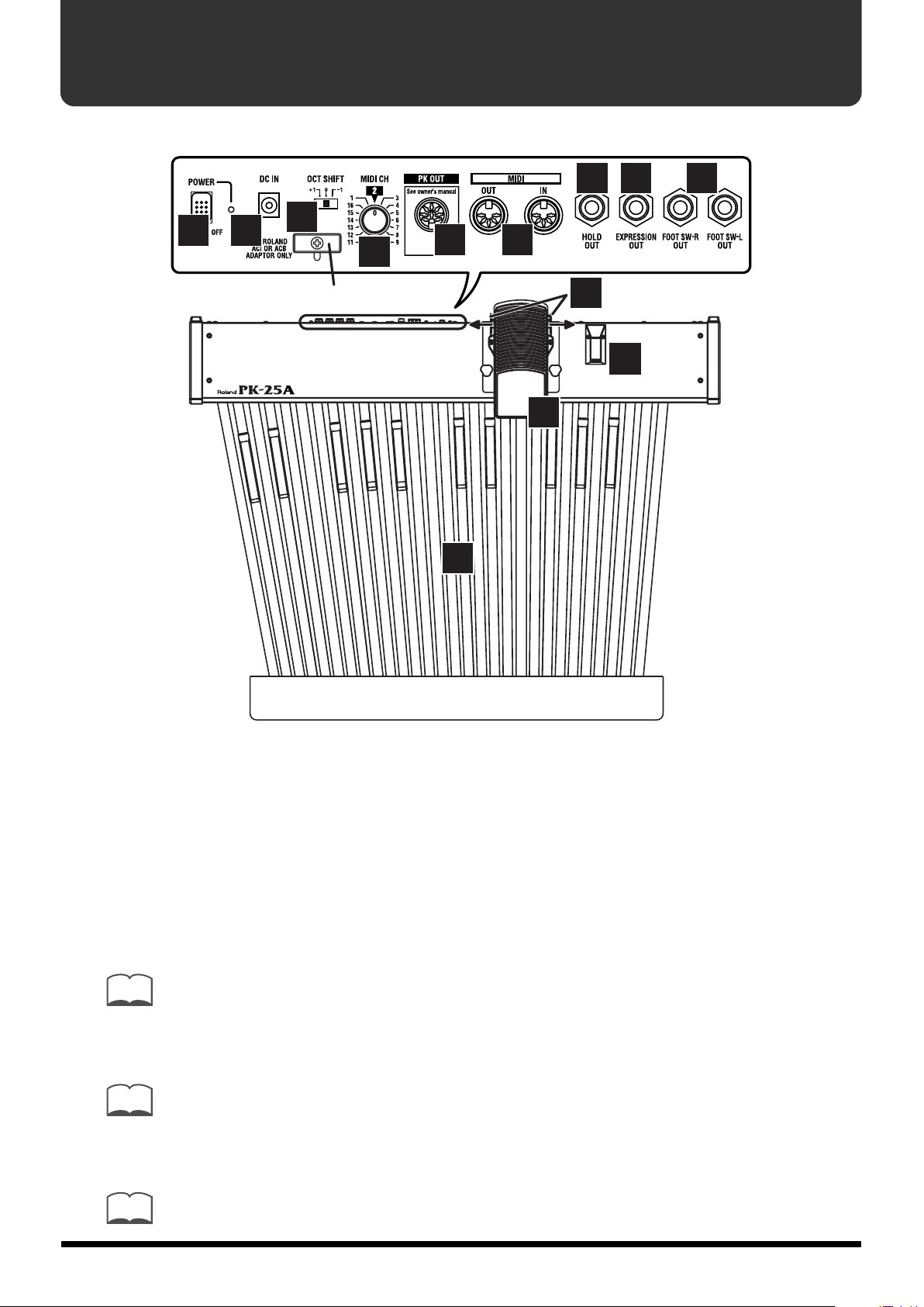
Names and Functions
Rear Panel
11 12 13
5 6
7
Cord Hook
8
9 10
3
4
2
1
1.
2.
3.
MEMO
4.
MEMO
5.
Pedal Keyboard
The PK-25A features a 25-note pedal keyboard that is ideal for organ performance.
Expression Pedal
Advancing the pedal will increase the volume, and returning the pedal toward yourself
will decrease the volume. For instructions on connecting it, refer to page 8.
Foot Switches
Two foot switches are built on the sides of the expression pedal.
You can control the connected devices by pressing the foot switch.
For more information on the foot switch functions when the PK-25A is connected to a VK-88 or
VK-8, refer to “Connecting to the VK-88” (p. 9) or “Connecting to the VK-8” (p. 10).
Hold Pedal
Pressing down on the Hold pedal holds (sustains) the sound from the connected device.
For more information on the foot switch functions when the PK-25A is connected to a VK-88 or
VK-8, refer to “Connecting to the VK-88” (p. 9) or “Connecting to the VK-8” (p. 10).
POWER Switch
This turns the power of the PK-25A on/off.
6
MEMO
If the PK cable is used to connect the PK-25A to the VK-88, the PK-25A will turn on/off in
tandem with the VK-88. The power switch of the PK-25A need not be switched on/off.
Page 7

6.
Cord Hook
The cord of the supplied
AC Adaptor
To the Power Outlet
DC IN Jack
Connect the supplied AC adaptor to this jack.
To prevent the inadvertent disruption of power to
your unit (should the plug be pulled out accidentally), and to avoid applying undue stress to the
AC adaptor jack, anchor the power cord using the
cord hook, as shown in the illustration.
7.
8.
9.
NOTE
10.
11.
OCT SHIFT (Octave Shift) Switch
When the PK-25A is connected to an external MIDI device other than a VK-88 or VK-8,
this switch allows you to transpose the pitch in octave units to match that of the connected device (p. 12).
MIDI CH (MIDI Channel Switching) Knob
This knob allows you to match the MIDI channel settings with other equipment when
the PK-25A is connected to an external MIDI device other than a VK-88 or VK-8 (p. 12).
PK OUT Connector
Use the PK cable that is supplied with the VK-88 to connect this connector to the VK-88.
After connecting to the VK-88, make sure to set the PEDAL KEYBOARD [SELECT]
switch on the VK-88’s rear panel to PK IN (VK-88 Owner’s Manual, p. 22).
Do not attempt to use any cable other than the PK cable, since this will cause malfunctions. This connector
cannot be used with the VK-8.
MIDI Connectors
Connect a VK-8 or external MIDI device here.
Use a MIDI cable (sold separately) to make the connections.
HOLD OUT (Hold Pedal output) Jack
This jack outputs the on/off data from the hold pedal.
Use a monaural cable (phone-phone) (sold separately) to make the connections.
NOTE
12.
NOTE
NOTE
13.
NOTE
If a cable is connected to this jack, Hold data will not be sent from the PK OUT connector or the MIDI
OUT connector.
EXPRESSION OUT (Expression pedal output) Jack
This jack outputs the data from the expression pedal.
Use a stereo cable (phone-phone) (sold separately) to make the connections.
The expression pedal is designed only for Roland/Boss products. Connecting it to products made by
manufacturers other than Roland or Boss may cause malfunctions.
If a cable is connected to this jack, Expression data will not be output from the PK OUT connector or
MIDI OUT connector.
FOOT SW-L OUT/FOOT SW-R OUT (Foot switch L output /Foot switch
R output) Jacks
These jacks output on/off data from the foot switches.
Use a monaural cable (phone-phone) (sold separately) to make the connections.
If a cable is connected to these jacks, on/off data from the foot switches will not be output from the PK OUT
connector or the MIDI OUT connector.
7
Page 8

Connections
2
Attaching the Expression Pedal
The PK-25A is shipped with the expression pedal detached. Before connecting the PK25A to another device, please attach the expression pedal.
NOTE
When attaching or detaching the expression pedal, be careful not to step on a knob bolt. When removing
the knob bolts, place them out of the reach of children. If a knob bolt is accidentally swallowed, consult a
doctor immediately.
To prevent malfunction and/or damage to speakers or other devices, always turn down the volume, and
turn off the power on all devices before making any connections.
1. Connect the expression pedal cable
to the connector in the upper part of
the PK-25A.
. While being careful not to pinch the
cable, place the expression pedal on
the PK-25A.
3. Use the three supplied knob bolts to
fasten the expression pedal, making
sure that the bolt holes are aligned.
Supplied Knob Bolts
(three point)
Knob bolt
View from Rear
NOTE
The connector in the upper part of the PK-25A is only for connecting the supplied expression pedal.
Connecting this to any device other than the PK-25A’s own expression pedal could result in malfunction.
8
Page 9

Connecting to the VK-88
Use the PK cable that is supplied with the VK-88 to connect the VK-88 and PK-25A.
MEMO
The supplied AC adaptor is not used. The PK-25A will be turned on/off by the power switch of
the VK-88, regardless of the position of the PK-25A’s own power switch.
PK IN Jack
PK cable that is supplied
with the VK-88
PK OUT Jack
The VK-88 includes a PK cable that is longer than
*
the PK cable supplied with the PK-25A. If you are
connecting the PK-25A to a VK-88, we recommend
using the PK cable that is supplied with the VK-88.
1.
2.
3.
NOTE
4.
5.
6.
NOTE
MEMO
Make sure that the VK-88’s power is turned off.
Set the PEDAL KEYBOARD [SELECT] switch (located on the rear panel
of the VK-88) to the PK IN position.
Use the PK cable that is supplied with the VK-88 to connect the VK88’s PK IN connector to the PK-25A’s PK OUT connector.
Once the connections have been completed, turn on power to your various devices in the order specified. By
turning on devices in the wrong order, you risk causing malfunction and/or damage to speakers and other
devices.
As explained on the VK-88 Owner’s Manual, turn on the power of the
VK-88.
Make sure that the indicator on the rear panel of the PK-25A is lit.
Play the pedal keyboard. If you hear the pedal part of the VK-88,
connections are complete.
This unit is equipped with a protection circuit. A brief interval (a few seconds) after power up is required
before the unit will operate normally.
If connecting the PK-25A to a VK-88, set the OCT SHIFT (Octave Shift) switch to the “0” position.
9
Page 10

MEMO
You can select the part that will be sustained when you press the Hold pedal.
→
HOLD PEDAL ASSIGN (VK-88 Owner’s Manual, p. 80)
MEMO
A variety of functions can be assigned to each foot switch (L/R).
→
PK FOOT L ASSIGN (VK-88 Owner’s Manual, p. 68)
→
PK FOOT R ASSIGN (VK-88 Owner’s Manual, p. 68)
Connecting to the VK-8
Use a MIDI cable to connect the VK-8 and PK-25A.
MIDI Cable
MIDI OUT Connector
MIDI PEDAL IN Connector
10
1.
2.
3.
NOTE
4.
5.
6.
Make sure that the power of the VK-8 and PK-25A is turned off.
Use a MIDI cable to connect the VK-8’s MIDI PEDAL IN connector to the
PK-25A’s MIDI OUT connector.
Connect the appropriate end of the AC adaptor to the DC IN jack. Then
connect the other end to a standard AC outlet.
Once the connections have been completed, turn on power to your various devices in the order specified. By
turning on devices in the wrong order, you risk causing malfunction and/or damage to speakers and other
devices.
Turn on the power of the PK-25A, and make sure that the indicator on
the PK-25A’s rear panel is lit.
As described in the VK-8 Owner’s Manual, turn on the power of the VK-
8.
Make sure that the Sub-Keyboard Function is on (VK-8 Owner’s
Manual p. 58).
Page 11

7.
Play the pedal keyboard. If the pedal part is heard from the VK-8,
connections are complete.
NOTE
MEMO
MEMO
MEMO
MEMO
This unit is equipped with a protection circuit. A brief interval (a few seconds) after power up is required
before the unit will operate normally.
Once you have made connections as described above, you can use the switches and pedals to
control the following functions.
•
Expression pedal: Control the volume of all parts of the Organ, and the Other Tones.
•
Foot switch L: Switch the rotary effect between slow/fast.
•
Foot switch R: Turn the rotary effect brake on/off.
•
Hold pedal: Hold (sustain) the sound of the Organ voice and Other Tones.
If connecting the PK-25A to a VK-8, set the OCT SHIFT (Octave Shift) switch to the “0” position.
When the PK-25A’s FOOT SW-L OUT/FOOT SW-R OUT/HOLD OUT jack is connected to the
VK-8’s CONTROL PEDAL jack, you can assign a variety of functions to the foot switch. Use a
mono cable (phone-phone) to make connections.
→
Assigning a Function to the Control Pedal (VK-8 Owner’s Manual, p. 40)
When the PK-25A’s EXPRESSION OUT jack is connected to the VK-8’s EXPRESSION PEDAL
jack, you can use the expression pedal to simultaneously control the volume of all parts of the
Organ and the Other Tones. Use a stereo cable (phone-phone) to make connections.
→
Using the Expression Pedal (VK-8 Owner’s Manual, p. 39)
When the PK-25A’s HOLD OUT jack is connected to the VK-8’s HOLD PEDAL jack, you can
play can sustain the sound by pressing the pedal. Use a monaural cable (phone-phone) to make
connections.
→
Using the Hold Pedal to Sustain the Sound (VK-8 Owner’s Manual, p. 42)
MEMO
NOTE
The PK-25A provides a “MIDI Merge” feature, which allows you to have the MIDI messages
received at MIDI IN be combined with the MIDI messages produced by playing the PK-25A
itself. The resulting merged data stream is then transmitted from the MIDI OUT connector.
Turn off the power of the PK-25A after turning off the power of VK-8.
Connecting to External MIDI Devices Other than the VK-88/VK-8
Use a MIDI cable to connect external MIDI devices to the PK-25A.
MEMO
1.
2.
MEMO
The PK-25A provides a “MIDI Merge” feature, which allows you to have the MIDI messages
received at MIDI IN be combined with the MIDI messages produced by playing the PK-25A
itself. The resulting merged data stream is then transmitted from the MIDI OUT connector.
Make sure that the power of the external device and PK-25A is turned
off.
Use a MIDI cable to connect the external device’s MIDI IN connector to
the PK-25A’s MIDI OUT connector.
If necessary, connect the FOOT SW-L OUT, FOOT SW-R OUT, and/or HOLD OUT jacks to the
corresponding connectors on the external MIDI device.
11
Page 12

NOTE
Once the connections have been completed, turn on power to your various devices in the order specified. By
turning on devices in the wrong order, you risk causing malfunction and/or damage to speakers and other
devices.
3.
4.
5.
6.
7.
NOTE
Turn on the power of the PK-25A, and make sure that the indicator on
the PK-25A’s rear panel is lit.
Turn on the power to the external MIDI device according to the
instructions in the owner’s manual for the device.
Set the PK-25A’s MIDI channel.
→
“Setting the MIDI Channel” (Next section)
Set the MIDI channel on the external MIDI device to match the channel
set for the PK-25A.
Play the pedal keyboard. If the pedal part is heard from the VK-8,
connections are complete.
Turn off the power of the PK-25A after turning off the power of the external MIDI device.
Setting the MIDI Channel
When connecting the PK-25A to external MIDI devices other than the VK-88 or VK-8, set
the PK-25A’s MIDI channel and the MIDI channel on the external MIDI device to the
same channel.
1.
MEMO
Turn the MIDI CH (MIDI Channel Switching) knob on the PK-25A’s rear
panel to switch the MIDI channel.
Setting the MIDI channel is unnecessary when the PK-25A is connected to a VK-88 or VK-8.
Changing the Pitch (Octave Shift)
You can change the pitch in octave increments, allowing you to match the pitch to that
of the connected device.
1.
MEMO
Switch the Octave Shift setting with the OCT SHIFT (Octave Shift)
switch on the PK-25A’s rear panel.
Set the switch to the “+1” position to raise the pitch one octave or to the “-1” position to
lower the pitch one octave.
If connecting the PK-25A to a VK-88 or VK-8, set the OCT SHIFT (Octave Shift) switch to the “0”
position.
12
Page 13

Appendix
Troubleshooting
If the PK-25A does not function as you expect, please check the following points first. If this does not resolve the
problem, contact your dealer or a nearby Roland service center.
◆
●
The power (indicator) does not come on when I turn on the
power switch.
◆
If the PK-25A is connected to a device that cannot use the
PK cable (such as the VK-8), the supplied AC adaptor
must be used. After connecting the AC adaptor correctly,
turn the power switch on.
●
The power (indicator) does not turn on/off when I turn the
PK-25A’s power switch on/off.
◆
The PK-25A’s power is switched on/off in ta
ndem with the VK-88 when it is connected to the VK-88
using the PK cable that is supplied with the VK-88. Make
sure that the VK-88’s power is turned on and the PK
cable is connected correctly.
●
The foot switch, hold pedal, and/or expression pedal do
not operate correctly.
◆
Make sure that the expression pedal cable is correctly
connected to the connector on the upper part of the PK25A (p. 7).
◆
If the PK cable is used to connect the PK-25A to the VK-88
•
Make sure that the cable is connected correctly (p. 7).
•
Check the settings of the switches or pedals.
Foot switch: VK-88 Owner’s Manual, p. 68 (PK FOOT
L ASSIGN/PK FOOT R ASSIGN)
Hold pedal: VK-88 Owner’s Manual, p. 80 (HOLD
PEDAL ASSIGN)
Expression pedal: VK-88 Owner’s Manual,
p. 82 (ORCHESTRAL TONES EXPRESSION)
◆
If a MIDI cable is used to connect the PK-25A to the VK-8
•
Check that the MIDI cable is connected correctly (p. 8).
•
If you wish to use the expression pedal to control the
volume of the Other Tones, use a stereo cable (phonephone) to connect the PK-25A’s EXPRESSION OUT
jack to the VK-8’s EXPRESSION PEDAL jack, or the
PK-25A’s EXPRESSION OUT jack to the VK-8’s
CONTROL PEDAL jack. (VK-8 Owner’s Manual, p.
40–41)
If MIDI and analog cables are used to connect the PK25A to the VK-8
•
Make sure that the polarity of the VK-8’s CONTROL
PEDAL jack is set to “Standard.” (VK-8 Owner’s
Manual, p. 56)
•
Make sure that a function is assigned to the VK-8’s
CONTROL PEDAL jack. (VK-8 Owner’s Manual, p.
40–41)
•
Use a stereo cable (phone-phone) when connecting the
PK-25A’s EXPRESSION OUT jack to the VK-8’s
EXPRESSION PEDAL jack, or the PK-25A’s
EXPRESSION OUT jack to the VK-8’s CONTROL
PEDAL jack.
●
Cannot assign a function to the foot switch.
◆
When the PK-25A is connected to the VK-8 without using
analog cables, functions other than Rotary Slow/Fast
(foot pedal L) and Rotary Brake (foot pedal R) cannot be
assigned.
●
No sound plays.
◆
When connecting to any external MIDI device other than
the VK-88 or VK-8, you must match the PK-25A’s MIDI
channel to the MIDI channel set for the connected device.
◆
If connecting the PK-25A to a VK-8, switch the SubKeyboard Function to ON. (VK-8 Owner’s Manual, p. 56)
●
Sounds are not playing correctly.
◆
Confirm whether or not the Octave Shift switch is set
correctly. If the PK-25A is connected to a VK-88 or VK-8,
set the Octave Shift switch to the “0” position.
Error Messages
In the following situations, the indicator of the rear panel of PK-25A will blink for several seconds.
Situation 1: It is possible that the MIDI cable has been
disconnected or is damaged.
Action 1: Check the MIDI cable connections.
Situation 1: MIDI data could not be received correctly.
Action 1: If the indicator continues blinking for an
extended period of time, there is a problem
with the content of the MIDI data.
13
Page 14

Specifications
Pedalboard: 25 keys
• Control: Expression Pedal
• Connectors: PK OUT Jack
• Power: DC 9 V: AC adaptor, or supplied from VK-88 via PK cable
Foot Switch (L, R)
Damper (Hold) Switch
MIDI CH (MIDI Channel Switching) Knob
OCT SHIFT (Octave Shift) Switch
Power Switch
MIDI Connectors (IN, OUT)
HOLD OUT Jack
EXPRESSION OUT Jack
FOOT SW-R OUT Jack
FOOT SW-L OUT Jack
DC IN Jack
• Current Draw: 120 mA (DC 9 V)
• Dimensions: 1068 (W) x 885 (D) x 283 (H) mm
42-1/16 (W) x 34-7/8 (D) x 11-3/16 (H) inches
• Weight: 29.0 kg / 63 lbs 15 oz
• Accessories: Owner’s Manual
AC Adaptor
PK cable
• Options: MIDI Cable, Analog Cable (Stereo, Monaural)
* In the interest of product improvement, the specifications and/or appearance of this unit are
subject to change without prior notice.
14
Page 15

MIDI Implementation
Model: PK-25A (MIDI Pedal Keyboard)
Date: Oct. 20, 2005
Version: 1.00
1. Recognized Receive Data
■
System Realtime Messages
Status
FEH
* By receiving an Active Sensing message, this unit enters the mode timing the interval
between incoming MIDI messages. If the interval exceeds 500 ms, this unit transmits
Note Off messages corresponding to the transmitted notes being On, and returns from
this mode.
2. Transmitted Data
■
Channel Voice Messages
●
Note off
Status
8nH kkH 40H
n = MIDI channel: 0H - FH (ch.1 - 16)
kk = note number: 18H - 48H (24 - 72)
●
Note on
Status
9nH kkH 78H
n = MIDI channel: 0H - FH (ch.1 - 16)
kk = note number: 18H - 48H (24 - 72)
●
Control Change
❍
Expression (Controller number 11)
Status
BnH 0BH vvH
n = MIDI channel: 0H - FH (ch.1 - 16)
vv = expression: 00H - 7FH (0 - 127)
* If the EXPRESSION OUT jack on the rear panel is in use, this unit doesn’t send
Expression message via MIDI.
2nd byte 3rd byte
2nd byte 3rd byte
2nd byte 3rd byte
■
System Realtime Message
●
Active sensing
Status
FEH
* This will be transmitted constantly at intervals of approximately 250 ms.
■
System Exclusive Messages
“Data Set 1 (DT1)” to control VK-8/7 is the only System Exclusive messages transmitted by
PK-25A.
●
Data Set1 DT1
Status
F0H 41H, 10H, 00H, 08H, 12H, aaH, F7H
Byte Remarks
F0H Exclusive status
41H ID number (Roland)
10H device ID
00H model ID
08H model ID (VK-7)
12H command ID (DT1)
aaH address MSB: The most significant byte of the address
bbH address
ccH address
ddH address LSB: The least significant byte of the address
eeH data: The actual data to be transmitted.
sum checksum
F7H EOX (End Of Exclusive)
* This unit sends the following messages to control ROTARY SOUND of the VK-8/7.
F0 41 10 00 08 12 02 00 10 3D ... F7
(Rotary Speed: Transmit by FOOT SW-L)
F0 41 10 00 08 12 02 00 10 3E ... F7
(Rotary Rotation: Transmit by FOOT SW-R)
Data byte Status
bbH, ccH, ddH, eeH, sum
❍
General Purpose Controller 3 (Controller number 18)
Status
BnH 12H vvH
n = MIDI channel: 0H - FH (ch.1 - 16)
vv = control value: 00H, 7FH (0, 127)
* This message will be sent by operating a foot switch locating left side of the expression
pedal.
* If a FOOT SW-L OUT jack on the rear panel is in use, the unit doesn’t send this message
via MIDI.
❍
General Purpose Controller 4 (Controller number 19)
Status
BnH 13H vvH
n = MIDI channel: 0H - FH (ch.1 - 16)
vv = control value: 00H, 7FH (0, 127)
* This message will be sent by operating a foot switch locating right side of the expression
pedal.
* If a FOOT SW-R OUT jack on the rear panel is in use, the unit doesn’t send this message
via MIDI.
❍
Hold 1 (Controller number 64)
Status
BnH 40H vvH
n = MIDI channel: 0H - FH (ch.1 - 16)
vv = control value: 00H, 7FH (0, 127)
* If a HOLD OUT jack on the rear panel is in use, the unit doesn’t send Hold 1 message via
MIDI.
2nd byte 3rd byte
2nd byte 3rd byte
2nd byte 3rd byte
15
Page 16

MIDI Implementation Chart
MIDI FOOTPEDAL
Date : Oct. 20, 2005
Model PK-25A
Function…
Basic
Channel
Mode
Note
Number :
Velocity
After
Touch
Pitch Bend x
Default
Changed
Default
Messages
Altered
True Voice
Note ON
Note OFF
Key’s
Ch’s
MIDI Implementation Chart
1 – 16
1 – 16
Mode 3
x
****************
24 – 72
****************
O (9n, v=120)
O (8n, v=64)
x
x
11
O
18
O
19
O
64
O
x
x
x
x
x
x
x
x
x
x
x
x
x
x
x
Version : 1.00
RemarksRecognizedTransmitted
Expression
General Purpose 3
General Purpose 4
Hold 1
Control
Change
Prog
Change
System Exclusive
System
Common
System
Real Time
Aux
Message
: True #
SongPos
SongSel
Tune
Clock
Commands
All Sound OFF
Reset All Controllers
Local ON/OFF
All Notes OFF
Active Sensing
Reset
x
****************
O *1
x
x
x
x
x
x
x
x
x
O
x
x
x
x
x
x
x
x
x
x
x
x
x
O
x
Notes
Mode 1 : OMNI ON, POLY
Mode 3 : OMNI OFF, POLY
16
*1 For controlling Rotary Sound of the VK-8/7
Mode 2 : OMNI ON, MONO
Mode 4 : OMNI OFF, MONO
O : Yes
x : No
Page 17

Information When you need repair service, call your nearest Roland Service Center or authorized Roland
distributor in your country as shown below.
AFRICA
EGYPT
Al Fanny Trading Office
9, EBN Hagar A1 Askalany
Street,
ARD E1 Golf, Heliopolis,
Cairo 11341, EGYPT
TEL: 20-2-417-1828
REUNION
Maison FO - YAM Marcel
25 Rue Jules Hermann,
Chaudron - BP79 97 491
Ste Clotilde Cedex,
REUNION ISLAND
TEL: (0262) 218-429
SOUTH AFRICA
That Other Music Shop(PTY)Ltd.
11 Melle St., Braamfontein,
Johannesbourg,
SOUTH AFRICA
TEL: (011) 403 4105
FAX: (011) 403 1234
Paul Bothner(PTY)Ltd.
Royal Cape Park, Unit 24
Londonderry Road, Ottery 7800
Cape Town, SOUTH AFRICA
TEL: (021) 799 4900
ASIA
CHINA
Roland Shanghai Electronics
Co.,Ltd.
5F. No.1500 Pingliang Road
Shanghai 200090, CHINA
TEL: (021) 5580-0800
Roland Shanghai Electronics
Co.,Ltd.
(BEIJING OFFICE)
10F. No.18 3 Section Anhuaxili
Chaoyang District Beijing
100011 CHINA
TEL: (010) 6426-5050
Roland Shanghai Electronics
Co.,Ltd.
(GUANGZHOU OFFICE)
2/F., No.30 Si You Nan Er Jie
Yi Xiang, Wu Yang Xin Cheng,
Guangzhou 510600, CHINA
TEL: (020) 8736-0428
HONG KONG
Tom Lee Music Co., Ltd.
Service Division
22-32 Pun Shan Street, Tsuen
Wan, New Territories,
HONG KONG
TEL: 2415 0911
Parsons Music Ltd.
8th Floor, Railway Plaza, 39
Chatham Road South, T.S.T,
Kowloon, HONG KONG
TEL: 2333 1863
INDIA
Rivera Digitec (India) Pvt. Ltd.
409, Nirman Kendra
Mahalaxmi Flats Compound
Off. Dr. Edwin Moses Road,
Mumbai-400011, INDIA
TEL: (022) 2493 9051
INDONESIA
PT Citra IntiRama
J1. Cideng Timur No. 15J-150
Jakarta Pusat
INDONESIA
TEL: (021) 6324170
KOREA
Cosmos Corporation
1461-9, Seocho-Dong,
Seocho Ku, Seoul, KOREA
TEL: (02) 3486-8855
MALAYSIA
Roland Asia Pacific Sdn. Bhd.
45-1, Block C2, Jalan PJU 1/39,
Dataran Prima, 47301 Petaling
Jaya, Selangor, MALAYSIA
TEL: (03) 7805-3263
PHILIPPINES
G.A. Yupangco & Co. Inc.
339 Gil J. Puyat Avenue
Makati, Metro Manila 1200,
PHILIPPINES
TEL: (02) 899 9801
SINGAPORE
SWEE LEE MUSIC
COMPANY PTE. LTD.
150 Sims Drive,
SINGAPORE 387381
TEL: 6846-3676
TAIWAN
ROLAND TAIWAN
ENTERPRISE CO., LTD.
Room 5, 9fl. No. 112 Chung
Shan N.Road Sec.2, Taipei,
TAIWAN, R.O.C.
TEL: (02) 2561 3339
THAILAND
Theera Music Co. , Ltd.
330 Soi Verng NakornKasem,
New Road, Sumpantawongse,
Bangkok 10100, THAILAND
TEL: (02) 224-8821
VIETNAM
SAIGON MUSIC
DISTRIBUTOR
(TAN DINH MUSIC)
138 Tran Quang Khai Street
Dist. 1, Ho Chi Minh City
VIETNAM
TEL: (08) 848-4068
AUSTRALIA/
NEW ZEALAND
AUSTRALIA/
NEW ZEALAND
Roland Corporation
Australia Pty.,Ltd.
38 Campbell Avenue
Dee Why West. NSW 2099
AUSTRALIA
For Australia
Tel: (02) 9982 8266
For New Zealand
Tel: (09) 3098 715
CENTRAL/LATIN
AMERICA
ARGENTINA
Instrumentos Musicales S.A.
Av.Santa Fe 2055
(1123) Buenos Aires
ARGENTINA
TEL: (011) 4508-2700
BARBADOS
A&B Music Supplies LTD
12 Webster Industrial Park
Wildey, St.Michael, Barbados
TEL: (246)430-1100
BRAZIL
Roland Brasil Ltda.
Rua San Jose, 780 Sala B
Parque Industrial San Jose
Cotia - Sao Paulo - SP, BRAZIL
TEL: (011) 4615 5666
CHILE
Comercial Fancy II S.A.
Rut.: 96.919.420-1
Nataniel Cox #739, 4th Floor
Santiago - Centro, CHILE
TEL: (02) 688-9540
COLOMBIA
Centro Musical Ltda.
Cra 43 B No 25 A 41 Bododega 9
Medellin, Colombia
TEL: (574)3812529
COSTA RICA
JUAN Bansbach Instrumentos
Musicales
Ave.1. Calle 11, Apartado 10237,
San Jose, COSTA RICA
TEL: 258-0211
CURACAO
Zeelandia Music Center Inc.
Orionweg 30
Curacao, Netherland Antilles
TEL:(305)5926866
DOMINICAN REPUBLIC
Instrumentos Fernando Giraldez
Calle Proyecto Central No.3
Ens.La Esperilla
Santo Domingo,
Dominican Republic
TEL:(809) 683 0305
ECUADOR
Mas Musika
Rumichaca 822 y Zaruma
Guayaquil - Ecuador
TEL:(593-4)2302364
EL SALVADOR
OMNI MUSIC
75 Avenida Norte y Final
Alameda Juan Pablo II,
Edificio No.4010 San Salvador,
EL SALVADOR
TEL: 262-0788
GUATEMALA
Casa Instrumental
Calzada Roosevelt 34-01,zona 11
Ciudad de Guatemala
Guatemala
TEL:(502) 599-2888
HONDURAS
Almacen Pajaro Azul S.A. de C.V.
BO.Paz Barahona
3 Ave.11 Calle S.O
San Pedro Sula, Honduras
TEL: (504) 553-2029
MARTINIQUE
Musique & Son
Z.I.Les Mangle
97232 Le Lamantin
Martinique F.W.I.
TEL: 596 596 426860
Gigamusic SARL
10 Rte De La Folie
97200 Fort De France
Martinique F.W.I.
TEL: 596 596 715222
MEXICO
Casa Veerkamp, s.a. de c.v.
Av. Toluca No. 323, Col. Olivar
de los Padres 01780 Mexico
D.F. MEXICO
TEL: (55) 5668-6699
NICARAGUA
Bansbach Instrumentos
Musicales Nicaragua
Altamira D'Este Calle Principal
de la Farmacia 5ta.Avenida
1 Cuadra al Lago.#503
Managua, Nicaragua
TEL: (505)277-2557
PANAMA
SUPRO MUNDIAL, S.A.
Boulevard Andrews, Albrook,
Panama City, REP. DE
PANAMA
TEL: 315-0101
PARAGUAY
Distribuidora De
Instrumentos Musicales
J.E. Olear y ESQ. Manduvira
Asuncion PARAGUAY
TEL: (595) 21 492147
PERU
Audionet
Distribuciones Musicales SAC
Juan Fanning 530
Miraflores
Lima - Peru
TEL: (511) 4461388
TRINIDAD
AMR Ltd
Ground Floor
Maritime Plaza
Barataria Trinidad W.I.
TEL: (868) 638 6385
URUGUAY
Todo Musica S.A.
Francisco Acuna de Figueroa
1771
C.P.: 11.800
Montevideo, URUGUAY
TEL: (02) 924-2335
VENEZUELA
Instrumentos Musicales
Allegro,C.A.
Av.las industrias edf.Guitar
import
#7 zona Industrial de Turumo
Caracas, Venezuela
TEL: (212) 244-1122
EUROPE
AUSTRIA
Roland Elektronische
Musikinstrumente HmbH.
Austrian Office
Eduard-Bodem-Gasse 8,
A-6020 Innsbruck, AUSTRIA
TEL: (0512) 26 44 260
BELGIUM/FRANCE/
HOLLAND/
LUXEMBOURG
Roland Central Europe N.V.
Houtstraat 3, B-2260, Oevel
(Westerlo) BELGIUM
TEL: (014) 575811
CZECH REP.
K-AUDIO
Kardasovska 626.
CZ-198 00 Praha 9,
CZECH REP.
TEL: (2) 666 10529
DENMARK
Roland Scandinavia A/S
Nordhavnsvej 7, Postbox 880,
DK-2100 Copenhagen
DENMARK
TEL: 3916 6200
FINLAND
Roland Scandinavia As, Filial
Finland
Elannontie 5
FIN-01510 Vantaa, FINLAND
TEL: (0)9 68 24 020
GERMANY
Roland Elektronische
Musikinstrumente HmbH.
Oststrasse 96, 22844
Norderstedt, GERMANY
TEL: (040) 52 60090
GREECE
STOLLAS S.A.
Music Sound Light
155, New National Road
Patras 26442, GREECE
TEL: 2610 435400
HUNGARY
Roland East Europe Ltd.
Warehouse Area ‘DEPO’ Pf.83
H-2046 Torokbalint,
HUNGARY
TEL: (23) 511011
IRELAND
Roland Ireland
G2 Calmount Park, Calmount
Avenue, Dublin 12
Republic of IRELAND
TEL: (01) 4294444
ITALY
Roland Italy S. p. A.
Viale delle Industrie 8,
20020 Arese, Milano, ITALY
TEL: (02) 937-78300
NORWAY
Roland Scandinavia Avd.
Kontor Norge
Lilleakerveien 2 Postboks 95
Lilleaker N-0216 Oslo
NORWAY
TEL: 2273 0074
POLAND
MX MUSIC SP.Z.O.O.
UL. Gibraltarska 4.
PL-03664 Warszawa POLAND
TEL: (022) 679 44 19
PORTUGAL
Roland Iberia, S.L.
Portugal Office
Cais das Pedras, 8/9-1 Dto
4050-465, Porto, PORTUGAL
TEL: 22 608 00 60
ROMANIA
FBS LINES
Piata Libertatii 1,
535500 Gheorgheni,
ROMANIA
TEL: (266) 364 609
RUSSIA
MuTek
Dorozhnaya ul.3,korp.6
117 545 Moscow, RUSSIA
TEL: (095) 981-4967
SPAIN
Roland Iberia, S.L.
Paseo García Faria, 33-35
08005 Barcelona SPAIN
TEL: 93 493 91 00
SWEDEN
Roland Scandinavia A/S
SWEDISH SALES OFFICE
Danvik Center 28, 2 tr.
S-131 30 Nacka SWEDEN
TEL: (0)8 702 00 20
SWITZERLAND
Roland (Switzerland) AG
Landstrasse 5, Postfach,
CH-4452 Itingen,
SWITZERLAND
TEL: (061) 927-8383
UKRAINE
TIC-TAC
Mira Str. 19/108
P.O. Box 180
295400 Munkachevo,
UKRAINE
TEL: (03131) 414-40
UNITED KINGDOM
Roland (U.K.) Ltd.
Atlantic Close, Swansea
Enterprise Park, SWANSEA
SA7 9FJ,
UNITED KINGDOM
TEL: (01792) 702701
MIDDLE EAST
BAHRAIN
Moon Stores
No.16, Bab Al Bahrain Avenue,
P.O.Box 247, Manama 304,
State of BAHRAIN
TEL: 17 211 005
CYPRUS
Radex Sound Equipment Ltd.
17, Diagorou Street, Nicosia,
CYPRUS
TEL: (022) 66-9426
IRAN
MOCO INC.
No.41 Nike St., Dr.Shariyati Ave.,
Roberoye Cerahe Mirdamad
Tehran, IRAN
TEL: (021) 285-4169
ISRAEL
Halilit P. Greenspoon & Sons
Ltd.
8 Retzif Ha'aliya Hashnya St.
Tel-Aviv-Yafo ISRAEL
TEL: (03) 6823666
JORDAN
MUSIC HOUSE CO. LTD.
FREDDY FOR MUSIC
P. O. Box 922846
Amman 11192 JORDAN
TEL: (06) 5692696
KUWAIT
EASA HUSAIN AL-YOUSIFI
& SONS CO.
Abdullah Salem Street,
Safat, KUWAIT
TEL: 243-6399
LEBANON
Chahine S.A.L.
Gerge Zeidan St., Chahine
Bldg., Achrafieh, P.O.Box: 165857
Beirut, LEBANON
TEL: (01) 20-1441
OMAN
TALENTZ CENTRE L.L.C.
Malatan House No.1
Al Noor Street, Ruwi
SULTANATE OF OMAN
TEL: 2478 3443
QATAR
Al Emadi Co. (Badie Studio &
Stores)
P.O. Box 62, Doha, QATAR
TEL: 4423-554
SAUDI ARABIA
aDawliah Universal
Electronics APL
Corniche Road, Aldossary
Bldg., 1st Floor, Alkhobar,
SAUDI ARABIA
P.O.Box 2154, Alkhobar 31952
SAUDI ARABIA
TEL: (03) 898 2081
SYRIA
Technical Light & Sound
Center
Rawda, Abdul Qader Jazairi St.
Bldg. No. 21, P.O.BOX 13520,
Damascus, SYRIA
TEL: (011) 223-5384
TURKEY
ZUHAL DIS TICARET A.S.
Galip Dede Cad. No.37
Beyoglu - Istanbul / TURKEY
TEL: (0212) 249 85 10
U.A.E.
Zak Electronics & Musical
Instruments Co. L.L.C.
Zabeel Road, Al Sherooq Bldg.,
No. 14, Grand Floor, Dubai,
U.A.E.
TEL: (04) 3360715
NORTH AMERICA
CANADA
Roland Canada Music Ltd.
(Head Office)
5480 Parkwood Way
Richmond B. C., V6V 2M4
CANADA
TEL: (604) 270 6626
Roland Canada Music Ltd.
(Toronto Office)
170 Admiral Boulevard
Mississauga On L5T 2N6
CANADA
TEL: (905) 362 9707
U. S. A.
Roland Corporation U.S.
5100 S. Eastern Avenue
Los Angeles, CA 90040-2938,
U. S. A.
TEL: (323) 890 3700
As of December 10, 2005 (ROLAND)
17
Page 18

For EU Countries
This product complies with the requirements of European Directive 89/336/EEC.
For the USA
FEDERAL COMMUNICATIONS COMMISSION
RADIO FREQUENCY INTERFERENCE STATEMENT
This equipment has been tested and found to comply with the limits for a Class B digital device, pursuant to Part 15 of the
FCC Rules. These limits are designed to provide reasonable protection against harmful interference in a residential
installation. This equipment generates, uses, and can radiate radio frequency energy and, if not installed and used in
accordance with the instructions, may cause harmful interference to radio communications. However, there is no guarantee
that interference will not occur in a particular installation. If this equipment does cause harmful interference to radio or
television reception, which can be determined by turning the equipment off and on, the user is encouraged to try to correct the
interference by one or more of the following measures:
– Reorient or relocate the receiving antenna.
– Increase the separation between the equipment and receiver.
– Connect the equipment into an outlet on a circuit different from that to which the receiver is connected.
– Consult the dealer or an experienced radio/TV technician for help.
This device complies with Part 15 of the FCC Rules. Operation is subject to the following two conditions:
(1) This device may not cause harmful interference, and
(2) This device must accept any interference received, including interference that may cause undesired operation.
Unauthorized changes or modification to this system can void the users authority to operate this equipment.
This equipment requires shielded interface cables in order to meet FCC class B Limit.
For Canada
NOTICE
This Class B digital apparatus meets all requirements of the Canadian Interference-Causing Equipment Regulations.
18
AVIS
Cet appareil numérique de la classe B respecte toutes les exigences du Règlement sur le matériel brouilleur du Canada.
 Loading...