

Page 1
OWNER’S MANUAL
Thank you, and congratulations on your choice of the Roland (FA-76).
Before using this unit, carefully read the sections entitled: “IMPORTANT SAFETY
INSTRUCTIONS” (Owner’s Manual p. 2), “USING THE UNIT SAFELY” (Owner’s
Manual p. 3), and “IMPORTANT NOTES” (Owner’s Manual p. 4). These sections
provide important information concerning the proper operation of the unit.
Additionally, in order to feel assured that you have gained a good grasp of every
feature provided by your new unit, Quick Start, Owner’s Manual, Sound/
Parameter List, and Q&A should be read in its entirety. The manual should be
saved and kept on hand as a convenient reference.
Copyright © 2001 ROLAND CORPORATION
All rights reserved. No part of this publication may be reproduced in any form without
the written permission of ROLAND CORPORATION.
Page 2
CAUTION
RISK OF ELECTRIC SHOCK
DO NOT OPEN
ATTENTION: RISQUE DE CHOC ELECTRIQUE NE PAS OUVRIR
CAUTION: TO REDUCE THE RISK OF ELECTRIC SHOCK,
DO NOT REMOVE COVER (OR BACK).
NO USER-SERVICEABLE PARTS INSIDE.
REFER SERVICING TO QUALIFIED SERVICE PERSONNEL.
The lightning flash with arrowhead symbol, within an
equilateral triangle, is intended to alert the user to the
presence of uninsulated “dangerous voltage” within the
product’s enclosure that may be of sufficient magnitude to
constitute a risk of electric shock to persons.
The exclamation point within an equilateral triangle is
intended to alert the user to the presence of important
operating and maintenance (servicing) instructions in the
literature accompanying the product.
INSTRUCTIONS PERTAINING TO A RISK OF FIRE, ELECTRIC SHOCK, OR INJURY TO PERSONS.
IMPORTANT SAFETY INSTRUCTIONS
SAVE THESE INSTRUCTIONS
WARNING - When using electric products, basic precautions should always be followed, including the following:
1. Read these instructions.
2. Keep these instructions.
3. Heed all warnings.
4. Follow all instructions.
5. Do not use this apparatus near water.
6. Clean only with a damp cloth.
7. Do not block any of the ventilation openings. Install in
accordance with the manufacturers instructions.
8. Do not install near any heat sources such as radiators,
heat registers, stoves, or other apparatus (including
amplifiers) that produce heat.
9. Do not defeat the safety purpose of the polarized or
grounding-type plug. A polarized plug has two blades with
one wider than the other. A grounding type plug has two
blades and a third grounding prong. The wide blade or the
third prong are provided for your safety. When the provided
plug does not fit into your outlet, consult an electrician for
replacement of the obsolete outlet.
WARNING:
IMPORTANT:
As the colours of the wires in the mains lead of this apparatus may not correspond with the coloured markings identifying
the terminals in your plug, proceed as follows:
The wire which is coloured GREEN-AND-YELLOW must be connected to the terminal in the plug which is marked by the
letter E or by the safety earth symbol or coloured GREEN or GREEN-AND-YELLOW.
The wire which is coloured BLUE must be connected to the terminal which is marked with the letter N or coloured BLACK.
The wire which is coloured BROWN must be connected to the terminal which is marked with the letter L or coloured RED.
THIS APPARATUS MUST BE EARTHED
THE WIRES IN THIS MAINS LEAD ARE COLOURED IN ACCORDANCE WITH THE FOLLOWING CODE.
GREEN-AND-YELLOW: EARTH, BLUE: NEUTRAL, BROWN: LIVE
10. Protect the power cord from being walked on or pinched
particularly at plugs, convenience receptacles, and the
point where they exit from the apparatus.
11. Only use attachments/accessories specified by the
manufacturer.
12. Never use with a cart, stand, tripod, bracket,
or table except as specified by the
manufacturer, or sold with the apparatus.
When a cart is used, use caution when
moving the cart/apparatus combination to
avoid injury from tip-over.
13. Unplug this apparatus during lightning storms or when
unused for long periods of time.
14. Refer all servicing to qualified service personnel. Servicing
is required when the apparatus has been damaged in any
way, such as power-supply cord or plug is damaged, liquid
has been spilled or objects have fallen into the apparatus,
the apparatus has been exposed to rain or moisture, does
not operate normally, or has been dropped.
For the U.K.
2
Page 3
Used for instructions intended to alert
the user to the risk of death or severe
injury should the unit be used
improperly.
Used for instructions intended to alert
the user to the risk of injury or material
damage should the unit be used
improperly.
* Material damage refers to damage or
other adverse effects caused with
respect to the home and all its
furnishings, as well to domestic
animals or pets.
The symbol alerts the user to important instructions
or warnings.The specific meaning of the symbol is
determined by the design contained within the
triangle. In the case of the symbol at left, it is used for
general cautions, warnings, or alerts to danger.
The symbol alerts the user to items that must never
be carried out (are forbidden). The specific thing that
must not be done is indicated by the design contained
within the circle. In the case of the symbol at left, it
means that the unit must never be disassembled.
The ● symbol alerts the user to things that must be
carried out. The specific thing that must be done is
indicated by the design contained within the circle. In
the case of the symbol at left, it means that the powercord plug must be unplugged from the outlet.
001
• Before using this unit, make sure to read the instructions
below, and the Owner’s Manual.
........................................................................................................................
002b
• Do not open or perform any internal modifications on the
unit. (The only exception would be where this manual
provides specific instructions which should be followed in
order to put in place user-installable options; see p. 196.)
........................................................................................................................
003
• Do not attempt to repair the unit, or replace parts within it
(except when this manual provides specific instructions
directing you to do so). Refer all servicing to your retailer,
the nearest Roland Service Center, or an authorized
Roland distributor, as listed on the “Information” page.
........................................................................................................................
004
• Never use or store the unit in places that are:
• Subject to temperature extremes (e.g., direct sunlight
in an enclosed vehicle, near a heating duct, on top of
heat-generating equipment); or are
• Damp (e.g., baths, washrooms, on wet floors); or are
• Humid; or are
• Exposed to rain; or are
• Dusty; or are
• Subject to high levels of vibration.
........................................................................................................................
005
• This unit should be used only with a rack or stand that is
recommended by Roland.
........................................................................................................................
006
• When using the unit with a rack or stand recommended
by Roland, the rack or stand must be carefully placed so it
is level and sure to remain stable. If not using a rack or
stand, you still need to make sure that any location you
choose for placing the unit provides a level surface that
will properly support the unit, and keep it from wobbling.
........................................................................................................................
008a
• The unit should be connected to a power supply only of
the type described in the operating instructions, or as
marked on the unit.
........................................................................................................................
008e
• Use only the attached power-supply cord.
........................................................................................................................
009
• Do not excessively twist or bend the power cord, nor place
heavy objects on it. Doing so can damage the cord,
producing severed elements and short circuits. Damaged
cords are fire and shock hazards!
........................................................................................................................
010
• This unit, either alone or in combination with an amplifier
and headphones or speakers, may be capable of
producing sound levels that could cause permanent
hearing loss. Do not operate for a long period of time at a
high volume level, or at a level that is uncomfortable. If
you experience any hearing loss or ringing in the ears, you
should immediately stop using the unit, and consult an
audiologist.
........................................................................................................................
011
• Do not allow any objects (e.g., flammable material, coins,
pins); or liquids of any kind (water, soft drinks, etc.) to
penetrate the unit.
........................................................................................................................
013
• In households with small children, an adult should
provide supervision until the child is capable of following
all the rules essential for the safe operation of the unit.
........................................................................................................................
014
• Protect the unit from strong impact.
(Do not drop it!)
........................................................................................................................
015
• Do not force the unit’s power-supply cord to share an
outlet with an unreasonable number of other devices. Be
especially careful when using extension cords—the total
power used by all devices you have connected to the
extension cord’s outlet must never exceed the power
rating (watts/amperes) for the extension cord. Excessive
loads can cause the insulation on the cord to heat up and
eventually melt through.
........................................................................................................................
3
Page 4
USING THE UNIT SAFELY
016
• Before using the unit in a foreign country, consult with
your retailer, the nearest Roland Service Center, or an
authorized Roland distributor, as listed on the “Information” page.
........................................................................................................................
022a
• Always turn the unit off and unplug the power cord
before attempting installation of the circuit board (SRJV80/SRX Series; Quick Start p. 3–4).
........................................................................................................................
101a
• The unit should be located so that its location or position
does not interfere with its proper ventilation.
........................................................................................................................
101c
• This unit for use only with Roland keyboard stand KS-12.
Use with other stands is capable of resulting in instability
causing possible injury.
........................................................................................................................
102b
• Always grasp only the plug on the power-supply cord
when plugging into, or unplugging from, an outlet or this
unit.
........................................................................................................................
104
• Try to prevent cords and cables from becoming entangled.
Also, all cords and cables should be placed so they are out
of the reach of children.
........................................................................................................................
106
• Never climb on top of, nor place heavy objects on the unit.
........................................................................................................................
107b
• Never handle the power cord or its plugs with wet hands
when plugging into, or unplugging from, an outlet or this
unit.
........................................................................................................................
108a
• Before moving the unit, disconnect the power plug from
the outlet, and pull out all cords from external devices.
........................................................................................................................
109a
• Before cleaning the unit, turn off the power and unplug
the power cord from the outlet (Quick Start p. 5).
........................................................................................................................
110a
• Whenever you suspect the possibility of lightning in your
area, pull the plug on the power cord out of the outlet.
........................................................................................................................
115a
• Install only the specified circuit board(s) (SR-JV80/SRX
Series). Remove only the specified screws (p. 196, p. 198).
........................................................................................................................
118
• Should you remove screws, make sure to put them in a
safe place out of children’s reach, so there is no chance of
them being swallowed accidentally.
........................................................................................................................
IMPORTANT NOTES
In addition to the items listed under “IMPORTANT SAFETY INSTRUCTIONS” and “USING THE UNIT SAFELY” on pages 2 and 3, please
read and observe the following:
Power Supply
301
• Do not use this unit on the same power circuit with any device
that will generate line noise (such as an electric motor or variable
lighting system).
307
• Before connecting this unit to other devices, turn off the power to
all units. This will help prevent malfunctions and/or damage to
speakers or other devices.
Placement
351
• Using the unit near power amplifiers (or other equipment
containing large power transformers) may induce hum. To
alleviate the problem, change the orientation of this unit; or move
it farther away from the source of interference.
352
• This device may interfere with radio and television reception. Do
not use this device in the vicinity of such receivers.
353
• Observe the following when using the unit’s floppy disk drive.
For further details, refer to “Before Using Floppy Disks.”
• Do not place the unit near devices that produce a strong
magnetic field (e.g., loudspeakers).
• Install the unit on a solid, level surface.
• Do not move the unit or subject it to vibration while the drive
is operating.
354a
• Do not expose the unit to direct sunlight, place it near devices that
radiate heat, leave it inside an enclosed vehicle, or otherwise
subject it to temperature extremes. Excessive heat can deform or
discolor the unit.
355
• To avoid possible breakdown, do not use the unit in a wet area,
such as an area exposed to rain or other moisture.
358
• Do not allow objects to remain on top of the keyboard. This can be
the cause of malfunction, such as keys ceasing to produce sound.
4
Page 5
IMPORTANT NOTES
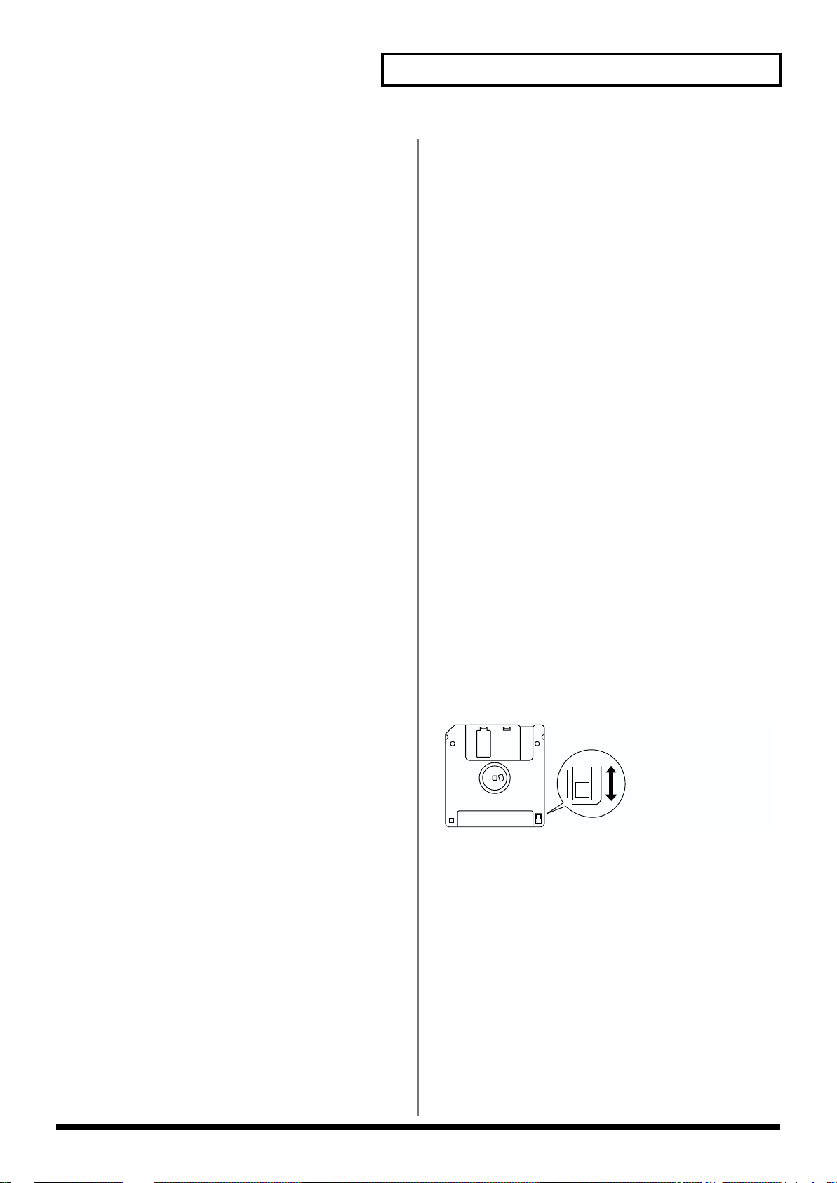
Protect tab
Write (writing permitted)
Protect (writing prohibited)
Maintenance
401a
• For everyday cleaning wipe the unit with a soft, dry cloth or one
that has been slightly dampened with water. To remove stubborn
dirt, use a cloth impregnated with a mild, non-abrasive detergent.
Afterwards, be sure to wipe the unit thoroughly with a soft, dry
cloth.
402
• Never use benzine, thinners, alcohol or solvents of any kind, to
avoid the possibility of discoloration and/or deformation.
Additional Precautions
551
• Please be aware that the contents of memory can be irretrievably
lost as a result of a malfunction, or the improper operation of the
unit. To protect yourself against the risk of loosing important data,
we recommend that you periodically save a backup copy of
important data you have stored in the unit’s memory on a floppy
disk.
552
• Unfortunately, it may be impossible to restore the contents of data
that was stored on a floppy disk, in the unit’s memory or another
MIDI device (e.g., a sequencer) once it has been lost. Roland
Corporation assumes no liability concerning such loss of data.
553
• Use a reasonable amount of care when using the unit’s buttons,
sliders, or other controls; and when using its jacks and connectors.
Rough handling can lead to malfunctions.
554
• Never strike or apply strong pressure to the display.
556
• When connecting / disconnecting all cables, grasp the connector
itself—never pull on the cable. This way you will avoid causing
shorts, or damage to the cable’s internal elements.
557
• A small amount of heat will radiate from the unit during normal
operation.
558a
• To avoid disturbing your neighbors, try to keep the unit’s volume
at reasonable levels. You may prefer to use headphones, so you do
not need to be concerned about those around you (especially
when it is late at night).
559a
• When you need to transport the unit, package it in the box
(including padding) that it came in, if possible. Otherwise, you
will need to use equivalent packaging materials.
561
• Use only the specified expression pedal (EV-5; sold separately). By
connecting any other expression pedals, you risk causing
malfunction and/or damage to the unit.
604
• To insert a disk, push it gently but firmly into the drive—it will
click into place. To remove a disk, press the EJECT button firmly.
Do not use excessive force to remove a disk which is lodged in the
drive.
605a
• Never attempt to remove a floppy disk from the drive while the
drive is operating (the indicator is lit); damage could result to both
the disk and the drive.
606
• Remove any disk from the drive before powering up or down.
607
• To prevent damage to the disk drive’s heads, always try to hold
the floppy disk in a level position (not tilted in any direction)
while inserting it into the drive. Push it in firmly, but gently.
Never use excessive force.
608
• To avoid the risk of malfunction and/or damage, insert only
floppy disks into the disk drive. Never insert any other type of
disk. Avoid getting paper clips, coins, or any other foreign objects
inside the drive.
Handling Floppy Disks
651
• Floppy disks contain a plastic disk with a thin coating of magnetic
storage medium. Microscopic precision is required to enable
storage of large amounts of data on such a small surface area. To
preserve their integrity, please observe the following when
handling floppy disks:
• Never touch the magnetic medium inside the disk.
• Do not use or store floppy disks in dirty or dusty areas.
• Do not subject floppy disks to temperature extremes (e.g.,
direct sunlight in an enclosed vehicle). Recommended temperature range: 10 to 50° C (50 to 122° F).
• Do not expose floppy disks to strong magnetic fields, such as
those generated by loudspeakers.
652
• Floppy disks have a “write protect” tab which can protect the disk
from accidental erasure. It is recommended that the tab be kept in
the PROTECT position, and moved to the WRITE position only
when you wish to write new data onto the disk.
Before Using Floppy Disks
Handling the Floppy Disk Drive
602
• Install the unit on a solid, level surface in an area free from
vibration. If the unit must be installed at an angle, be sure the
installation does not exceed the permissible range: upward, 2°;
downward, 18°.
603
• Avoid using the unit immediately after it has been moved to a
location with a level of humidity that is greatly different than its
former location. Rapid changes in the environment can cause
condensation to form inside the drive, which will adversely affect
the operation of the drive and/or damage floppy disks. When the
unit has been moved, allow it to become accustomed to the new
environment (allow a few hours) before operating it.
653
• The identification label should be firmly affixed to the disk.
Should the label come loose while the disk is in the drive, it may
be difficult to remove the disk.
654
• Store all disks in a safe place to avoid damaging them, and to
protect them from dust, dirt, and other hazards. By using a dirty
or dust-ridden disk, you risk damaging the disk, as well as
causing the disk drive to malfunction.
5
Page 6
How To Use This Manual
This owner’s manual is organized as follows. Before you start
reading it, we’d like to suggest going through the Quick Start
manual. For parameter lists, sound lists, and MIDI implementation,
refer to the separate “Sound/Parameter List.” In addition, the
separate “Q&A” provides answers for frequently asked questions
about the Fantom, and example applications for your reference.
Overview of the Fantom
This explains the structure of the Fantom, and basic operation.
Reading it is essential for understanding Fantom operational
procedures.
Playing in Patch Mode
This explains how to play the Fantom in Patch mode. Reading it is
essential for understanding Fantom operational procedures.
Creating a Patch
This chapter explains how to create patches, and describes what the
patch parameters do and how they are composed. Read this chapter
when you wish to create patches.
Creating a Rhythm Set
This chapter explains how to create rhythm sets, and describes what
the rhythm set parameters do and how they are composed. Read this
chapter when you wish to create rhythm sets.
Recording a Song
This explains how to record a song using the Fantom’s sequencer.
Reading it is essential for understanding Fantom operational
procedures.
Editing a Song
This chapter explains song editing and song settings in detail. Read
this when you wish to edit a song that you’ve recorded.
Playing Phrase with One Finger
(RPS Function)
This explains the settings of the RPS (Realtime Phrase Sequence)
function, and how to use it for performance. Read this chapter when
you wish to use the RPS.
Changing Tones in Realtime
This explains how to use the D Beam controller and realtime
controllers to modify the sound, and how to make the necessary
settings. Read this when you want to modify the sound in realtime.
Applying Effects
This chapter explains how to make settings for the Fantom’s onboard
effects, and describes the type and operation of each effect. Be sure to
read this when adding effects to patches and performances.
Playing in Performance Mode
This explains how to play the Fantom in Performance mode.
Reading it is essential for understanding Fantom operational
procedures.
Creating a Performance
This chapter explains how to create performances, and describes
what the performance parameters do and how they are composed.
Read this chapter when you wish to create performances.
Playing in Multitimbre Mode
This explains how to play the Fantom in Multitimbre mode. Reading
it is essential for understanding Fantom operational procedures.
Creating a Multitimbre
This explains how to create a multitimbre, and the functions and
structure of the multitimbre parameters. Read this when you wish to
create a multitimbre.
Playing Back a Song
This explains how to play back a song using the Fantom’s sequencer.
Reading it is essential for understanding Fantom operational
procedures.
Settings Common to All Modes
(System Function)
This chapter describes how the System parameters that determine
the Fantom’s operation environment work and how these
parameters are organized. Read it as necessary.
Disk-Related Functions (Disk Utility)
This chapter covers disk-related operations such as saving data to
disk and loading data from disk. Read it as necessary.
Transmitting Sound Settings/
Restoring the Factory Settings
This explains how to transmit data to an external MIDI device or to
the Fantom (Data Transfer), and how to restore all data of the
Fantom to the factory settings (Factory Reset). Read it as necessary.
Installing the Wave Expansion Board
This explains how to install a Wave Expansion Board (sold
separately). Read it as necessary.
6
Page 7
Notation Used in This Owner’s Manual
To make operation procedures easy to understand, the following
notation system is adopted:
Characters and numbers in square brackets [ ] indicate buttons and
knobs on the front panel. For example, [MODE] indicates the MODE
button, and [CURSOR] indicates the cursor buttons
( , ,,).
(p. **) refers to pages within the manual.
In this manual, when any particular parameter is referred to, the
name of the parameter is given, and this is then followed (in
parenthesis) by information detailing its mode/edit group. For
example: Mono/Poly parameter (PATCH/General).
Below are the meanings of the symbols preceding certain sentences
in the text.
These are notes. Be sure to read them.
How To Use This Manual
The display screens printed in this owner’s manual are based on
the factory settings. However, please be aware that in some cases
they may differ from the actual factory settings.
These are reference memos. Read it as necessary.
These are hints for operating the Fantom. Read it as necessary.
These provide information from related reference pages. Read it
as necessary.
7
Page 8

Contents
IMPORTANT NOTES ...............................................................................4
How To Use This Manual........................................................................6
Notation Used in This Owner’s Manual...................................................................................... 7
Main Features........................................................................................14
Panel Descriptions................................................................................16
Front Panel.................................................................................................................................................16
Rear Panel..................................................................................................................................................18
Overview of the Fantom .......................................................................19
How the Fantom Is Organized...............................................................................................................19
Basic Structure...............................................................................................................................19
Classification of Fantom Sound Types.......................................................................................19
About Simultaneous Polyphony................................................................................................. 21
About Memory..........................................................................................................................................22
Temporary Memory......................................................................................................................22
Rewritable Memory......................................................................................................................22
Non-Rewritable Memory............................................................................................................. 22
About the Onboard Effects ..................................................................................................................... 23
Effect Types....................................................................................................................................23
How Effects Units Work in Different Modes............................................................................23
About the Sequencer................................................................................................................................ 24
What Is a Song? .............................................................................................................................24
What Is a Track?............................................................................................................................24
Songs and the Sound Generator Mode...................................................................................... 25
How Phrase Tracks, Parts and MIDI Channels Interact.......................................................... 25
Positions for Storing a Song......................................................................................................... 26
Basic Operation of the Fantom...............................................................................................................27
Switching the Sound Generator Mode ([MODE])....................................................................27
Switching Screens from the Menu ([MENU])........................................................................... 28
Viewing a List of Patches or Other Data ([LIST]).....................................................................28
About the [1]–[8] Buttons.............................................................................................................28
Moving the Cursor........................................................................................................................29
Modifying a Value ........................................................................................................................29
Assigning a Name.........................................................................................................................30
Playing in Patch Mode..........................................................................31
About the PATCH PLAY Screen............................................................................................................31
Displaying PATCH PLAY Screen............................................................................................... 31
Selecting a Patch .......................................................................................................................................32
Selecting Favorite Patches (Favorite Sound).............................................................................33
Selecting Patches from the List....................................................................................................33
Auditioning Patches (Phrase Preview)......................................................................................34
Selecting Patches by Category (Patch Finder) ..........................................................................34
Transposing the Keyboard in Octave Units (Octave Shift)................................................................ 35
Transposing the Keyboard in Semitone Steps (Transpose)................................................................ 36
Selecting the Tones That Will Sound (Tone On/Off).......................................................................... 36
Playing Single Notes (Mono).................................................................................................................. 37
Creating Smooth Pitch Changes (Portamento) ....................................................................................37
Playing Arpeggios (Arpeggiator)...........................................................................................................38
Holding an Arpeggio.................................................................................................................... 38
Simulating a Rhythm Guitar .......................................................................................................38
Using an External MIDI Keyboard to Play Arpeggios............................................................39
Making Arpeggiator Settings......................................................................................................39
8
Page 9

Contents
Playing Percussion Instruments.............................................................................................................40
Selecting a Rhythm Set................................................................................................................. 40
Playing a Rhythm Set ...................................................................................................................41
Playing Rhythm Patterns from the Keyboard......................................................................................41
Holding the Playback of a Rhythm Pattern ..............................................................................41
Making Rhythm Pattern Settings................................................................................................ 41
Creating a Patch....................................................................................42
How to Make the Patch Settings ............................................................................................................42
Initializing Patch Settings (Init)................................................................................................... 43
Copying Patch Settings (Copy)...................................................................................................43
Cautions When Selecting a Waveform ......................................................................................44
Saving Patches You’ve Created (Write) ................................................................................................45
Auditioning the Save-Destination Patch (Compare) ...............................................................46
Registering a Favorite Patch (Favorite Sound).........................................................................46
Functions of Patch Parameters ...............................................................................................................47
Settings Common to the Entire Patch (General).......................................................................47
Arpeggiator Settings (Arpeggio) ................................................................................................51
Realtime Controller / D Beam Controller Settings (Controller)............................................52
Setting Effects for a Patch (Effects/MFX/MFX Control/Chorus/Reverb)..........................53
Matrix Control Settings (Matrix Ctrl)......................................................................................... 54
Changing How a Tone Is Sounded (TMT) ................................................................................56
Modifying Waveforms (Wave) ...................................................................................................59
Modifying Pitch (Pitch)................................................................................................................60
Modifying the Brightness of a Sound with a Filter (TVF).......................................................62
Adjusting the Volume (TVA) ......................................................................................................64
Modulating Sounds (LFO)........................................................................................................... 66
Creating a Rhythm Set .........................................................................69
How to Make the Rhythm Set Settings .................................................................................................69
Initializing Rhythm Set Settings (Init)........................................................................................ 69
Copying Rhythm Set Settings (Copy)........................................................................................70
Cautions When Selecting a Waveform ......................................................................................71
Saving Rhythm Sets You’ve Created (Write) .......................................................................................72
Auditioning the Save-Destination Rhythm Set (Compare) ....................................................73
Registering Favorite Rhythm Sets (Favorite Sound)................................................................ 73
Functions of Rhythm Set Parameters ....................................................................................................74
Settings Common to the Entire Rhythm Set (General)............................................................74
Rhythm Pattern Settings (Rhythm Ptn) .....................................................................................75
Realtime Controller / D Beam Controller Settings (Controller)............................................76
Setting Effects for a Rhythm Set (Effects/MFX/MFX Control/Chorus/Reverb)............... 77
Changing How a Rhythm Tone Is Sounded (WMT) ...............................................................77
Modifying Pitch (Pitch)................................................................................................................79
Modifying the Brightness of a Sound with a Filter (TVF).......................................................80
Adjusting the Volume (TVA) ......................................................................................................82
Playing in Performance Mode..............................................................84
About the PERFORMANCE PLAY Screen...........................................................................................84
Displaying PERFORMANCE PLAY Screen..............................................................................84
Selecting a Performance...........................................................................................................................85
Selecting Favorite Performances (Favorite Sound).................................................................. 86
Selecting Performances from the List......................................................................................... 86
Combining and Playing Sounds Together (Layer)..............................................................................87
Playing Different Sounds in Different Areas of the Keyboard (Split) ..............................................87
Playing Arpeggios in a Specific Region of the Keyboard...................................................................88
Playing Rhythm Patterns in a Specific Region of the Keyboard .......................................................89
9
Page 10

Contents
Using the Fantom As a Master Keyboard.............................................................................................90
Changing the Connections between Keyboard and Sound Generator (Zone) ....................90
Confirming MIDI Information for Each Part (Part Information) ......................................................90
Creating a Performance .......................................................................91
How to Make the Performance Settings................................................................................................91
Initializing Performance Settings (Init)......................................................................................91
Copying Performance Settings (Copy) ......................................................................................92
Saving Performance You’ve Created (Write).......................................................................................93
Registering a Favorite Performance (Favorite Sound) ............................................................ 93
Functions of Performance Parameters...................................................................................................94
Settings Common to the Entire Performance (General).......................................................... 94
Arpeggiator Settings (Arpeggio) ................................................................................................95
Rhythm Pattern Settings (Rhythm Ptn) .....................................................................................96
Realtime Controller / D Beam Controller Settings (Controller)............................................97
Zone Settings (Zone)..................................................................................................................... 98
Making Settings for Each Part (Part)........................................................................................ 100
Making Settings for Receiving MIDI (MIDI)...........................................................................103
Setting Effects for a Performance (Effects/MFX/MFX Control/Chorus/Reverb)...........104
Scale Tune Settings (Scale Tune)...............................................................................................104
Changing the Settings of the Patch Assigned to a Part..................................................................... 105
Playing in Multitimbre Mode ..............................................................106
About the MULTITIMBRE PLAY screen............................................................................................ 106
Displaying the MULTITIMBRE PLAY screen ........................................................................106
Selecting a Multitimbre..........................................................................................................................107
Selecting Multitimbres from a List ...........................................................................................107
Playing Back a Song...............................................................................................................................108
Selecting a Part to Play from the Keyboard (Current Part)..............................................................108
Selecting a Part to Play Individually (Solo)........................................................................................ 108
Silencing the Playback of a Specific Part (Mute)................................................................................ 109
Assigning a Different Patch to a Part ..................................................................................................109
Adjusting the Volume and Pan of Each Part......................................................................................109
Recording an Arpeggio Performance.................................................................................................. 110
Recording the Performance of a Rhythm Pattern..............................................................................110
Confirming MIDI Information for Each Part (Part Information).........................................111
Creating a Multitimbre........................................................................112
How to Make the Multitimbre Settings...............................................................................................112
Initializing Multitimbre Settings (Init).....................................................................................112
Copying Multitimbre Settings (Copy) .....................................................................................113
Saving Multitimbre You’ve Created (Write)......................................................................................114
Functions of Multitimbre Parameters..................................................................................................115
Settings Common to the Entire Multitimbre (General)......................................................... 115
Making Settings for Each Part (Part)........................................................................................ 115
Making Settings for Receiving MIDI (MIDI)...........................................................................118
Setting Effects for a Multitimbre (Effects/MFX/MFX Control/Chorus/Reverb)............120
Scale Tune Settings (Scale Tune)...............................................................................................120
Changing the Settings of the Patch Assigned to a Part..................................................................... 121
10
Page 11

Contents
Playing Back a Song...........................................................................122
Playing a Song Immediately from Disk (Quick Play)....................................................................... 122
Playing Back Songs Consecutively (Chain Play)...............................................................................122
Creating a Chain.......................................................................................................................... 122
Saving a Chain to Disk (Save) ...................................................................................................123
Loading a Chain from Disk (Load)........................................................................................... 124
Playing a Chain ...........................................................................................................................124
Various Playback Methods ...................................................................................................................124
Fast-Forward and Rewind During Playback ..........................................................................124
Playing Back Correctly from the Middle of the Song (MIDI Update)................................. 124
Muting the Playback of a Specific Instrument........................................................................125
Changing the Playback Tempo of a Song................................................................................125
Playing a Song Back at a Fixed Tempo (Muting the Tempo Track) ....................................125
Playing Back a S-MRC Format Song ........................................................................................125
Playing Back a Song Repeatedly (Loop Play).........................................................................125
Using the D Beam Controller to Start/Stop Song Playback .................................................126
Recording Songs ................................................................................127
Two Recording Methods............................................................................................................ 127
Before You Record a New Song ...........................................................................................................127
Select the Sound to be Used for Recording .............................................................................127
Erasing the Song from Internal Memory (Song Initialize)....................................................127
Specify the Time Signature........................................................................................................ 128
Recording Your Performance as You Play It (Realtime Recording) ...............................................129
Basic Operation for Realtime Recording .................................................................................129
Recording Tempo Changes in a Song (Tempo Recording)................................................... 130
Loop Recording and Punch-In Recording...............................................................................130
Correct the Timing of Your Playing as You Record (Recording Quantize) .......................131
Selecting the Sequencer Data that will Be Recorded (Recording Select) ............................131
Erasing Unwanted Data While You Record (Realtime Erase).............................................. 132
Auditioning Sounds or Phrases While Recording (Rehearsal Function)............................ 132
Inputting Data One Step at a Time (Step Recording)........................................................................ 132
Inputting Notes and Rests .........................................................................................................132
Assigning a Pattern to a Phrase Track .....................................................................................134
Saving a Recorded Song on Disk .........................................................................................................135
Editing Songs......................................................................................136
Loading the Song You Want to Edit.................................................................................................... 136
Using Different Sound Generators for Each Track ................................................................136
Silencing the Playback of a Track (Mute) ................................................................................137
Overall Settings for the Song................................................................................................................137
Assigning a Name to a Song (Song Name) .............................................................................137
Assigning a Name to a Pattern (Pattern Name) .....................................................................138
Assigning Markers (Locate Positions) to a Song....................................................................138
Specifying the Area of a Song that will Repeat (Loop Points)..............................................139
Editing Sequencer Data Over the Specified Range (Track Edit) .....................................................139
Basic Operation for Track Editing ............................................................................................139
Aligning a Song’s Timing (Quantize) ......................................................................................140
Erasing Unwanted Performance Data (Erase)........................................................................142
Deleting Unwanted Measures (Delete)....................................................................................143
Copying Phrases (Copy) ............................................................................................................143
Inserting a Blank Measure (Insert Measure)...........................................................................145
Transpose the Key (Transpose).................................................................................................145
Changing the Velocity (Volume) (Change Velocity) .............................................................146
Changing the MIDI Channel (Change Channel).................................................................... 147
Modifying the Length of Notes (Change Gate Time)............................................................ 147
Combining Two Phrase Tracks or Patterns into One (Merge) .............................................148
11
Page 12

Contents
Extracting and Moving a Part of Sequencer Data (Extract)..................................................149
Shifting Performance Data Forward and Back (Shift Clock)................................................ 150
Thinning Out the Sequencer Data (Data Thin)....................................................................... 151
Swapping Two Phrase Tracks or Patterns (Exchange).......................................................... 152
Adjusting the Song’s Playback Time (Time Fit) .....................................................................152
Deleting Blank Measures (Truncate)........................................................................................153
Editing Individual Items of Sequencer Data (Micro Edit)................................................................153
Viewing Sequencer Data (in the Microscope Window) ........................................................153
Sequencer Data Handled by a Phrase Track/Pattern............................................................ 154
Viewing sequencer data (View)................................................................................................ 155
Editing the Sequencer Data .......................................................................................................155
Inserting Sequencer Data (Create)............................................................................................156
Erasing Sequencer Data (Erase) ................................................................................................156
Moving Sequencer Data (Move) ...............................................................................................157
Copying Sequencer Data (Copy) ..............................................................................................157
Changing the Tempo Midway Through the Song .................................................................158
Changing the Time Signature Midway Through the Song................................................... 158
Playing a Phrase at the Touch of a Finger (RPS Function) ............159
Before You Use the RPS Function........................................................................................................159
Record a Pattern..........................................................................................................................159
Settings for the RPS Function.................................................................................................... 159
Using the RPS Function While You Perform...................................................................................... 160
Performing with the RPS Function from an External MIDI Keyboard............................... 161
Recording a Performance Using the RPS Function................................................................161
Modifying the Sound in Real Time ....................................................162
Waving Your Hand Over the D Beam to Modify the Sound (D Beam Controller)...................... 162
Making Settings for the D Beam Controller............................................................................ 162
Using Knobs or Buttons to Modify the Sound (Realtime Controller) ............................................ 163
Making Realtime Controller Settings....................................................................................... 163
Using a Pedal to Modify the Sound (Control Pedal)......................................................................... 164
Making Control Pedal Settings .................................................................................................164
Adding Effects.....................................................................................165
Turning Effects On and Off................................................................................................................... 165
Applying Effects in Patch Mode .......................................................................................................... 165
Specifying How the Sound Will Be Output (Effects).............................................................165
Signal Flow Diagram and Parameters .....................................................................................166
Applying Effects in Performance Mode or Multitimbre Mode.......................................................170
Specifying How the Sound Will Be Output (Effects).............................................................170
Signal Flow Diagram and Parameters .....................................................................................171
Making Multi-Effects Settings (MFX/MFX Control) ........................................................................174
Setting Procedure........................................................................................................................ 174
Functions of Parameters............................................................................................................. 175
Making Chorus Settings (Chorus) .......................................................................................................176
Setting Procedure........................................................................................................................ 176
Functions of Parameters............................................................................................................. 176
Making Reverb Settings (Reverb) ........................................................................................................177
Setting Procedure........................................................................................................................ 177
Functions of Parameters............................................................................................................. 177
12
Page 13

Contents
Settings Common to All Modes (System Function) ........................178
How to Make the System Function Settings....................................................................................... 178
Initializing the System Settings (Init)....................................................................................... 178
Saving the System Settings (Write)......................................................................................................178
Functions of System Parameters ..........................................................................................................179
Settings Common to the Entire System (General)..................................................................179
Sequencer Settings (Sequencer).................................................................................................180
MIDI Settings (MIDI)..................................................................................................................182
Controller Settings (Controller) ................................................................................................184
Equalizer settings (EQ)...............................................................................................................185
Phrase Preview Settings (Preview)...........................................................................................185
Scale Tune settings (Scale Tune)...............................................................................................186
Disk-Related Functions (Disk Utility)................................................187
About Disk Utility.................................................................................................................................. 187
Basic Disk Utility Operations................................................................................................................187
Selecting the Type of Files Displayed in the File List (View)........................................................... 188
Loading a File from Disk into the Fantom (Load)............................................................................. 188
Loading Individual Tracks/Patterns of Song Data................................................................ 188
Loading Individual Items of Sound Data................................................................................189
Saving Data on Disk (Save)...................................................................................................................189
Copying a File to Another Name (Copy)............................................................................................190
Renaming a File (Rename) ....................................................................................................................191
Deleting Unwanted Files (Delete)........................................................................................................191
Executing Disk-Related Functions (Tools).......................................................................................... 191
Preparing a Disk for Use by the Fantom .................................................................................191
Modifying the Name of the Disk..............................................................................................192
Checking Files Recorded on Disk............................................................................................. 192
Creating a Duplicate Disk..........................................................................................................193
Transmitting Sound Settings/Reset to Default Factory Settings ...194
Transmitting Sound Settings (Data Transfer) ....................................................................................194
Transmitting Data to an External MIDI Device......................................................................194
Transmitting Data to User Memory.........................................................................................195
Reset to Default Factory Settings (Factory Reset)..............................................................................195
Installing the Wave Expansion Board...............................................196
Cautions When Installing an Wave Expansion Board...................................................................... 196
How to Install a Wave Expansion Board............................................................................................196
Checking the Installed Wave Expansion Boards...............................................................................197
Installation de la carte d’expansion Wave
(French language for Canadian Safety Standard) ...........................198
Précautions à prendre lors de l’installation d’une carte d’expansion Wave .................................198
Installation d’une carte d’expansion Wave ........................................................................................198
Vérification des cartes d’extension audio aprés installation............................................................199
Specifications......................................................................................200
13
Page 14
Main Features
● A synthesizer with the operability
and playability of a musical
instrument
The category of synthesizers known as “workstations”—consisting
of a sound generator section that creates the sound, a controller
section, and a sequencer section to produce music—has taken its
own evolutionary path, adding various new functionality that opens
up new possibilities of musical expression and creation. On the other
hand, access to such functionality has generally been provided
through a restrictive, complex interface, which has all too often
hampered the creativity of the musician.
The Fantom not only features superb operability for performance,
but also is comprehensively designed to support the musician’s
creativity in every area, including composition. It lets you work
seamlessly through every aspect of the music production process,
from performance to composition, allowing you to hold onto your
inspiration.
● Consolidated interface design with
large graphic LCD
The Fantom features a large quarter-VGA sized LCD. The graphical
display uses four levels of grayscale to simultaneously show all
relevant settings for sounds or sequencer operations, guaranteeing
smooth operation.
Since a large amount of data can be displayed at once, buttons and
knobs are laid out simply, letting you access a desired parameter
with a minimum of operation. The interface is designed with your
creativity as the first priority.
● Top-level sound generator for
maximum expressive power
The Fantom contains the same type of 64-voice/16-part multitimbral
sound generator as on the XV-5080, acclaimed by music production
professionals. The total of 896 preset patches include new patches
that have been tuned specifically for the Fantom to take advantage of
its keyboard, knobs, and other realtime controllers.
Four-level velocity switching lets you move between four stereo
waves, for the same amazing expressive power as on the XV-5080.
The spaciousness of the sound field, tonal changes controlled by
velocity, and endless details of expressive nuance are at your
fingertips. Matrix Control lets you vary large numbers of parameters
at once, and can be controlled using realtime controllers such as the
knobs and D Beam control. The Fantom’s dynamic expressive power
can be controlled by simple operations.
Wave Expansions Boards can also be installed to freely customize
your Fantom for your favorite musical styles or applications. Two
slots for the SRX series expansion boards allow the addition of highquality sounds using a maximum of 64 M bytes of high-quality wave
memory, and another slot lets you install one of the wide selection of
SR-JV80 series expansion boards.
In addition to four parallel outputs, which can be used as two stereo
pairs, S/P DIF digital out (both optical and coaxial) is also provided.
The Fantom is a great match for any digital recording system.
● Power effects including COSM
effects
The effects indispensable for synthesizer sound creation are
provided—in studio quality.
For reverb, a DSP equivalent to SRV-3030 quality is built-in,
delivering clear reverb with smooth decays.
The total of 90 types of multi-effects (M-FX) include not only effects
such as RSS, 3D delay, and slicer, but also effects that use Roland’s
proprietary COSM modeling technology, such as guitar amp
simulations, guitar multi’s, bass multi’s, and keyboard multi’s.
In Multitimbre mode and Performance mode, three types of M-FX
can be used simultaneously, letting you use different M-FX effects on
a desired part. What’s more, a two-band EQ is provided for each
output jack.
● Comprehensive music production
with a superior performance
sequencer based on the MRC-Pro
The Fantom contains a 16-track sequencer based on the MRC-Pro
sequencer, delivering high resolution that captures every expressive
detail of your performance, and providing speedy data entry and
editing for both realtime and step recording. In conjunction with the
power sound generator, the Fantom is a serious music production
environment in a single package.
In addition, the Fantom lets you start recording immediately from
any mode (whether you are editing sounds or performing), simply
by pressing the [REC] button. You can record your improvisations in
real time, and create songs based on your captured inspirations.
It goes without saying that you can use Micro editing to edit your
recorded data in every detail. Since the large display lets you view 16
tracks of recorded data at once, editing can be performed faster,
more efficiently, and in greater detail than on previous workstations.
Sequencer data can be saved and loaded in the native MRC format
or as SMF. The built-in floppy disk drive makes it easy to exchange
data with another sequencer or computer.
The Fantom boasts a new Multitimbre mode. By displaying 16 parts
simultaneously, this lets you quickly create orchestrations, and
makes song arrangements simple and intuitive.
14
Page 15
Main Features
● Functions that stimulate your
creativity
The Fantom provides numerous functions that enhance its
playability for realtime performance, and let you develop this into
musical productions.
Numerous drum patterns based in actual professional drum playing
are built in. Twelve types of pattern variations including fills are
assigned to an octave of the keyboard, allowing you to perform the
drum part in real time. In addition, the drums can be made to play at
a steady, natural tempo, regardless of the timing at which you press
the keys.
A newly developed arpeggiator is also built-in. In addition to
complex phrases that would be impossible to play by hand, you can
also use the arpeggiator to play phrases that are similar to actual
performance. Furthermore, the D Beam and other realtime
controllers can be used to modify the arpeggio style. This not only
makes for a dramatic leap in expressive potential during a live
performance, but also supports your own playing.
Phrases played by rhythm patterns or the arpeggiator can be
recorded on the sequencer just as they are played. Your realtime
performance can be saved instantly as song data, or even used as a
template for a step-recorded phrase.
In addition, patterns created on the sequencer can be triggered by
the keyboard and played by the RPS (Realtime Phrase Sequence)
function. Rhythm patterns and complex phrases created using the
arpeggiator can be recorded on the sequencer, and then played in
real time, for amazing live performance possibilities.
● Designed to be a true musical
instrument
In a departure from the straight-line design of previous
workstations, the Fantom features a distinctive design, which
proclaims its worthiness as a true musical instrument, while at the
same time projecting a sense of quiet dignity.
● General MIDI- and General MIDI 2-
Compatible
The Fantom is compatible with both General MIDI and General
MIDI 2 standards. Any General MIDI and/or General MIDI 2
compatible music data (GM score) can be played back on the
Fantom.
General MIDI
General MIDI is a set of recommendations which seeks to
provide a way to go beyond the limitations of proprietary
designs, and standardize the MIDI capabilities of sound
generating devices. Sound generating devices and music files
that meet the General MIDI standard bear the General MIDI
logo ( ). Music files bearing the General MIDI logo can be
played back using any General MIDI sound generating unit to
produce essentially the same musical performance.
General MIDI 2
The upwardly compatible General MIDI 2 ( )
recommendations pick up where the original General MIDI left
off, offering enhanced expressive capabilities, and even greater
compatibility. Issues that were not covered by the original
General MIDI recommendations, such as how sounds are to be
edited, and how effects should be handled, have now been
precisely defined. Moreover, the available sounds have been
expanded. General MIDI 2 compliant sound generators are
capable of reliably playing back music files that carry either the
General MIDI or General MIDI 2 logo.
In some cases, the conventional form of General MIDI, which
does not include the new enhancements, is referred to as
“General MIDI 1” as a way of distinguishing it from General
MIDI 2.
15
Page 16

Panel Descriptions
5
Front Panel
2
3
1
4
6
10
1
Floppy Disk Drive
3.5” 2DD/2HD floppy disks can be used. To remove the disk, press
the eject button located at the right of the disk drive.
Subsequently, this manual will abbreviate “floppy disk” as “disk.”
2
D BEAM
You can apply a variety of effects to sounds simply by moving your
hand. → (p. 162)
[ON/OFF]
Switches the D Beam controller on/off.
5
[ ]–[ ]
The operation will depend on the parameter or function that is
assigned.
Perform functions related to the arpeggiator, rhythm pattern
function, and sequencer playback and recording.
[ARPEGGIO]
Switches the Arpeggiator on/off.
[RHYTHM]
Switches Rhythm pattern function on/off.
[RESET]
Moves the song position to the first measure. → (p. 124)
7 8 9
3
Volume Slider
Adjusts the overall volume that is output from the rear panel
OUTPUT jacks and PHONES jack. → (Quick Start; p. 4)
4
REALTIME CONTROL
You can assign a variety of parameters and functions to the four
knobs and four buttons, and use them to modify the sound in
realtime. → (p. 163)
[ ]–[ ]
The operation will depend on the parameter or function that is
assigned.
[BWD]
Moves the song position to the first beat of the previous measure. →
(p. 124)
[FWD]
Moves the song position to the first beat of the next measure. → (p.
124)
[STOP/PLAY]
Controls sequencer stop/play.
While stopped, you can hold down [SHIFT] and operate this to
perform MIDI Update. → (p. 124)
[REC]
The display changes to the Recording Standby window. → (p. 129)
16
Page 17
Panel Descriptions
9
10
VALUE Dial
This is used to modify values. If you hold down [SHIFT] as you turn
the VALUE dial, the value will change in greater increments. → (p.
29)
[DEC], [INC]
This is used to modify values. If you keep on holding down one
button while pressing the other, the value change accelerates. If you
press one of these buttons while holding down [SHIFT], the value
will change in bigger increments. → (p. 29)
[CURSOR]
Moves the cursor location up/down/left/right. → (p. 29)
[SHIFT]/[REGISTRY]
SHIFT: This button is used in conjunction with other buttons to
execute various functions.
REGISTRY: By holding down this button and pressing [1]–[8], you
can register a favorite sound. → (p. 46, p. 73, p. 94)
[BEAT] (Beat Indicator)
This blinks in sync with the tempo and beat of the song.
6
Display
This displays information regarding the operation you are
performing
7
[1]–[8]
These buttons let you select/register your favorite patches or
performances. The lower part of the screen will show the names of
the favorite sounds you’ve registered. → (p. 28)
During editing, these buttons execute a variety of functions, and
their function will differ depending on the screen. → (p. 28)
8
[MODE]
Opens the MODE window. → (p. 27)
[JUMP]/[BANK]
JUMP: This button is used in conjunction with the cursor buttons to
jump the cursor location.
BANK: By holding down this button and pressing [1]–[8], you can
select the favorite sound bank. → (p. 33, p. 86)
[EXIT]
Return to the PLAY screen, or close the currently open window. In
some screens, this causes the currently executing function to be
aborted.
Pitch Bend/Modulation Lever
This allows you to control pitch bend or apply vibrato. → (Quick
Start; p. 27)
[MENU]
Opens the MENU window. The contents of the menu will depend on
the current mode. → (p. 28)
[LIST]
Opens the LIST window. The contents of the list will depend on the
current location of the cursor. → (p. 28)
17
Page 18
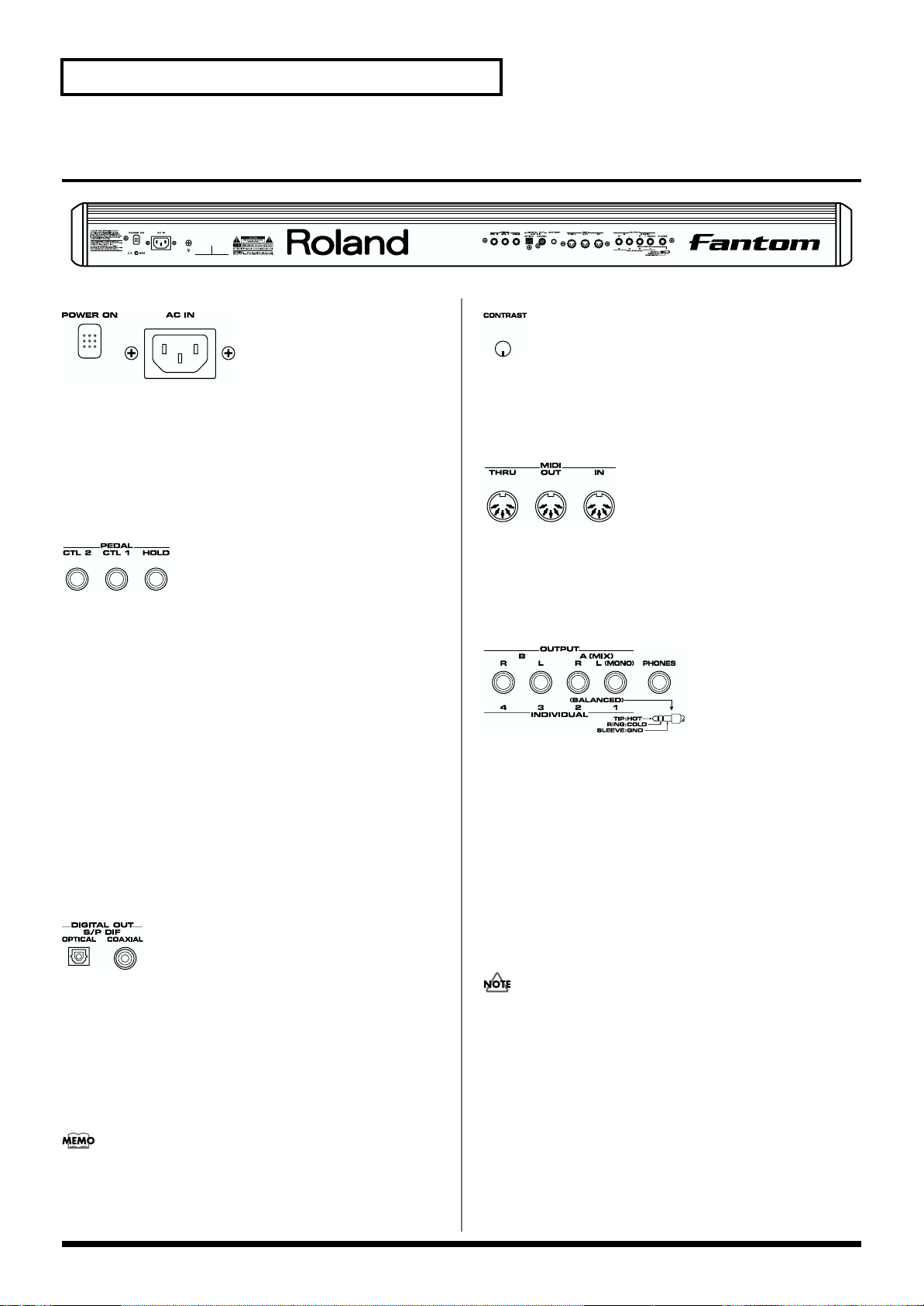
Panel Descriptions
Rear Panel
fig.00-02
fig.00-03
POWER ON Switch
Press to turn the power on/off. → (Quick Start; p. 4)
AC Inlet
Connect the included power cord to this inlet. → (Quick Start; p. 3)
fig.00-04
CTL 1, CTL 2 PEDAL Jack
You can connect optional expression pedals (EV-5, etc.) to these
jacks. By assigning a desired function to a pedal, you can use it to
select or modify sound or perform various other control. You can
also connect optional pedal switches (DP-2, DP-6, etc.) to sustain
sound. → (Quick Start; p. 29)
HOLD PEDAL Jack
An optional pedal switch (DP-2, DP-6, etc.) can be connected to this
jack for use as a hold pedal. → (Quick Start; p. 28)
This can also be set so it supports the use of half-pedaling
techniques. So, after connecting an optional expression pedal (EV-5,
etc.), you can employ pedal work to achieve even finer control in
performances in which piano tones are used. → (p. 184)
fig.00-05
fig.00-06
CONTRAST Knob
Adjusts the display contrast. → (Quick Start; p. 5)
fig.00-07
MIDI Connectors (IN, OUT, THRU)
These connectors can be connected to other MIDI devices to receive
and transmit MIDI messages.
fig.00-08
OUTPUT A (MIX) Jacks (L (MONO), R)
These jacks output the audio signal to the connected mixer/amplifier
system in stereo. For mono output, use the L jack. → (Quick Start; p.
3)
OUTPUT B Jacks (L, R)
These jacks output the audio signal to the connected mixer/amplifier
system in stereo.
INDIVIDUAL 1–4 Jacks
These jacks output audio signals in mono to an amp or mixer.
DIGITAL OUT Connectors
(S/P DIF OPTICAL, S/P DIF COAXIAL)
The Fantom features both optical and coaxial digital out connectors
(conforming to S/P DIF).
These connectors output a digital audio signal (stereo). The output
signal is identical to the signal that is output from the OUTPUT A
(MIX) jacks.
S/P DIF is a digital interface format used for consumer digital
audio devices.
18
The setting determining whether these jacks are used as stereo
OUTPUT jacks or monaural INDIVIDUAL jacks is made with
the Output Assign setting (p. 168, p. 172).
PHONES Jack
This is the jack for connecting headphones (sold separately). →
(Quick Start; p. 3)
Page 19
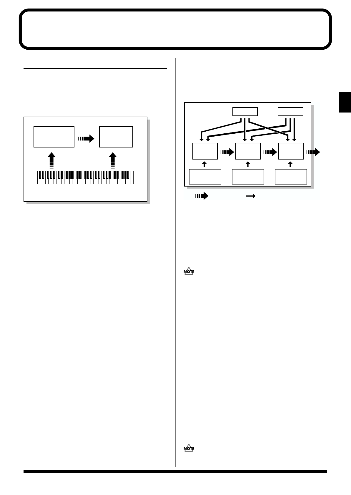
Overview of the Fantom
WG
Pitch
Envelope
TVF
TVF
Envelope
TVA
Envelope
TVA
LFO 1 LFO 2
control signal
Tone
audio signal
How the Fantom Is Organized
Basic Structure
Broadly speaking, the Fantom consists of a keyboard controller
section, a sound generator section, and a sequencer section.
These sections are internally connected via MIDI.
fig.01-01.e
Sequencer
Section
Recording
Keyboard Controller Section (controllers
such as keyboard, pitch bend lever, etc.)
Playback
Keyboard Controller Section
This section consists of the keyboard, pitch bend/modulation lever,
panel knobs and buttons, and D Beam controller. It also includes any
pedals that may be connected to the rear panel. The performance
information generated when you do things such as press/release a
key, or depress the hold pedal is converted into MIDI messages and
sent to the sound generator section, sequencer section, and/or an
external MIDI device.
Sound Generator Section
The sound generator section produces the sound. It receives MIDI
messages from the keyboard controller section and sequencer section
and/or from an external MIDI device, generates musical sound
according to the MIDI messages that were received, and outputs the
sound as an analog signal from the output jacks or headphone jack.
Sequencer Section
This section records operations of the keyboard controller section as
MIDI messages, and transmits the recorded MIDI messages to the
sound generator section. MIDI messages recorded on the sequencer
can also be transmitted from the MIDI OUT connector to allow the
Fantom to also control external MIDI devices.
Sound
Generator
Section
Play
Tones
On the Fantom, the tones are the smallest unit of sound. However, it
is not possible to play a tone by itself. The patch is the unit of sound
which can be played, and the tones are the basic building blocks
which make up the patch.
fig.01-02.e
Tones consist of the following five components.
WG (Wave Generator)
Specifies the PCM waveform (wave) that is the basis of the sound,
and determines how the pitch of the sound will change.
The Fantom has 1,083 different waveforms. All patches built into the
Fantom consist of combinations of tones which are created based on
these waveforms.
There are four wave generators for each rhythm tone (percussion
instrument sounds).
TVF (Time Variant Filter)
Specifies how the frequency components of the sound will change.
TVA (Time Variant Amplifier)
Specifies the volume changes and the sound’s position in a stereo
soundfield.
Envelope
You use Envelope to initiate changes to occur to a sound over time.
There are separate envelopes for Pitch, TVF (filter), and TVA (volume).
For example if you wish to modify the way in which the sound attacks
or decays over time, you would adjust the TVA envelope.
Overview of the Fantom
Classification of Fantom Sound Types
When using the Fantom, you will notice that a variety of different
categories come into play when working with sounds. What follows
is a simple explanation of each sound category.
LFO (Low Frequency Oscillator)
Use the LFO to create cyclic changes (modulation) in a sound. The
Fantom has two LFOs. Either one or both can be applied to effect the
WG (pitch), TVF (filter) and/or TVA (volume). When an LFO is
applied to the WG pitch, a vibrato effect is produced. When an LFO is
applied to the TVF cutoff frequency, a wah effect is produced. When
an LFO is applied to the TVA volume, a tremolo effect is produced.
LFO is not included in the rhythm tones (percussion instrument
sounds).
19
Page 20
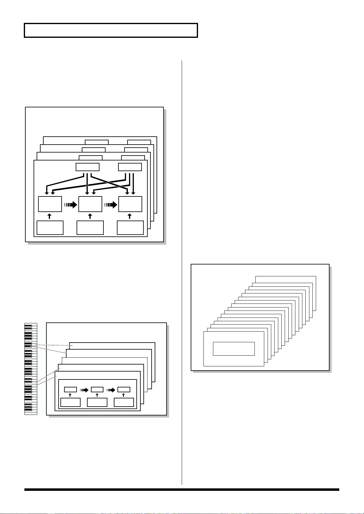
Overview of the Fantom
Performance/Multitimbre
Part 16
Part 1
Patch/
Rhythm Set
Patches
Patches are the basic sound configurations that you play during a
performance. Each patch can be configured by combining up to four
tones. How the four tones are combined is determined by the
Structure Type parameter (PATCH/TMT) (p. 56).
fig.01-03.e
Patch
Tone 4
Tone 3
Tone 2
Tone 1
WG
Pitch
Envelope
LFO 1 LFO 2
TVF
TVF
Envelope
TVA
TVA
Envelope
Rhythm Sets
Rhythm sets are groups of a number of different percussion
instrument sounds. Since percussion instruments generally do not
play melodies, there is no need for a percussion instrument sound to
be able to play a scale on the keyboard. It is, however, more
important that as many percussion instruments as possible be
available to you at the same time. Therefore, each key (note number)
of a rhythm set will produce a different percussion instrument.
fig.01-04.e
Each percussion instrument consists of the following four elements.
(For details, refer to the explanations for “Tones.”)
WG (Wave Generator)
TVF (Time Variant Filter)
TVA (Time Variant Amplifier)
Envelope
Multitimbre
A multitimbre consists of a patch or rhythm set assigned to each of
the 16 parts, and can simultaneously handle 16 sounds. This allows
you to create a set of sounds for use with a song you create on the
sequencer, or to enjoy ensemble performance. From the keyboard,
you can play only the currently selected part (the “current part”).
Because the Fantom sound generator can control multiple sounds
(instruments) it is called a Multi-timbral sound generator.
Performances
A performance is like a multitimbre in that it also has a patch or
rhythm set assigned to each of the 16 parts, and can simultaneously
handle 16 sounds. However, unlike a multitimbre, you can play
multiple parts simultaneously from the keyboard, allowing you to
play multiple patches simultaneously (Layer) or in separate regions
of the keyboard (Split).
fig.01-05.e
Rhythm Set
Note Number 97 (C#7)
Note Number 36 (C2)
Note Number 35 (B1)
Rhythm Tone (Percussion instrument sound)
WG
Pitch
Envelope
20
Note Number 98 (D7)
TVF
TVF
Envelope
TVA
TVA
Envelope
Part
A part is the place to which a patch or rhythm set is assigned when
using the Fantom in Multitimbre mode or Performance mode. A
single multitimbre/performance comprises sixteen parts, with a
patch or rhythm set being assigned to each part.
Page 21
About Simultaneous Polyphony
The Fantom can play a maximum of 64 sounds simultaneously. The
following paragraphs discuss what this means, and what will
happen when more than 64 simultaneous voices are requested from
the Fantom.
Calculating the Number of Voices
Being Used
The Fantom is able to play up to 64 notes simultaneously. The
polyphony, or the number of voices (sounds) does not refer only to
the number of sounds actually being played, but changes according
to the number of tones used in the patches, and the number of
Waves used in the tones. The following method is used to calculate
the number of sounds used for one patch being played.
(Number of Sounds Being Played) x (Number of tones Used by
Patches Being Played) x (Number of Waves Used in the tones)
For example, with a patch combining four tones, each of which uses
two Waves, the actual number of sounds being played comes to 8.
Also, when playing in Multitimbre mode or Performance mode, the
number of sounds for each part is counted to obtain the total number
of sounds for all parts.
Overview of the Fantom
It is not possible to make Voice Reserve settings that would
cause the total of all parts to be greater than 64 voices.
Overview of the Fantom
How a Patch Sounds
When the Fantom is requested to play more than 64 voices
simultaneously, currently sounding notes will be turned off to make
room for newly requested notes. The note with the lowest priority
will be turned off first. The order of priority is determined by the
Voice Priority setting (p. 47).
Voice Priority can be set either to “LAST” or “LOUDEST.” When
“LAST” is selected, a newly requested note that exceeds the 64 voice
limit will cause the first-played of the currently sounding notes to be
turned off. When “LOUDEST” is selected, the quietest of the
currently sounding notes will be turned off. Usually, “LAST” is
selected.
Note Priority in Multitimbre/
Performance Mode
Since Multitimbre/Performance mode is usually used to play an
ensemble consisting of several patches, it is important to decide
which parts take priority. Priority is specified by the Voice Reserve
settings (p. 47). When a note within a patch needs to be turned off to
make room for a new note, the Voice Priority setting of the patch
will apply.
Voice Reserve
The Fantom has a Voice Reserve function that lets you reserve a
minimum number of notes that will always be available for each
part. For example if Voice Reserve is set to “10” for part 16, part 16
will always have 10 notes of sound-producing capacity available to it
even if a total of more than 64 notes (total for all parts) are being
requested. When you make Voice Reserve settings, you need to take
into account the number of notes you want to play on each part as
well as the number of tones used by the selected patch (p. 102, p.
118).
21
Page 22
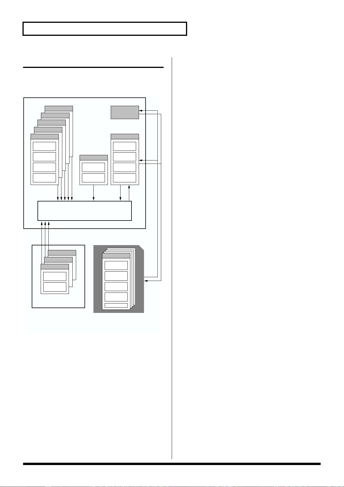
Overview of the Fantom
About Memory
Patch and performance settings are stored in what is referred to as
memory. There are three kind of memory: temporary, rewritable,
and non-rewritable.
fig.01-06.e
Fantom
Preset E (PR-E)
Preset D (PR-D)
Preset C (PR-C)
Preset B (PR-B)
Preset A (PR-A)
Patch
128
Rhythm Set
16
* 1
Multitimbre
16
* 1
Performance
64
* 1
Select
EXP C Slot (XP-C)
EXP B Slot (XP-B)
EXP A Slot (XP-A)
Patch
Rhythm Set
Wave Expansion Board
GM (GM2)
Patch
256
Rhythm Set
9
* 2
Temporary Area
System
User (USER)
Patch
128
Rhythm Set
16
Multitimbre
16
Performance
64
Data File (.SVD)
Patch
128
Rhythm Set
16
Multitimbre
16
Performance
64
System
WriteSelectSelectSelect
Load
Save
Rewritable Memory
System Memory
System memory stores system parameter settings that determine
how the Fantom functions.
User Memory
User memory is where you normally store the data you need. USER
memory contains 128 patches, 16 rhythm sets, 16 multitimbres, and
64 performances.
Disk (Optional: 3.5” 2DD, 2HD)
Patches, multitimbres, performances, and system settings can be
stored on disk together as a single file.
Non-Rewritable Memory
Preset Memory
Data in Preset memory cannot be rewritten. However, you can call
up settings from preset memory into the temporary area, modify
them and then store the modified data in rewritable memory (except
GM2).
Wave Expansion Boards
(optional: SR-JV80/SRX Series)
The Fantom can be equipped with up to three Wave Expansion
Boards (one SR-JV80 series, two SRX series). Wave Expansion Boards
contain Wave data, as well as patches and rhythm sets that use this
Wave data, which can be called directly into the temporary area and
played.
Disk
* 1 Only in PR-A (PRST)
* 2 The selected Patches/Rhythm Sets cannot be changed.
Temporary Memory
Temporary Area
This is the area that holds the data for the patch, multitimbre, or
performance that you’ve selected using the panel buttons.
When you play the keyboard or play back a sequence, sound is
produced based on data in the temporary area. When you edit a
patch, multitimbre, or performance, you do not directly modify the
data in memory; rather, you call up the data into the temporary area,
and edit it there.
Settings in the temporary area are temporary, and will be lost when
the power is turned off or when you select another patch/
multitimbre/performance. To keep the settings you have modified,
you must write them into rewritable memory.
22
Page 23
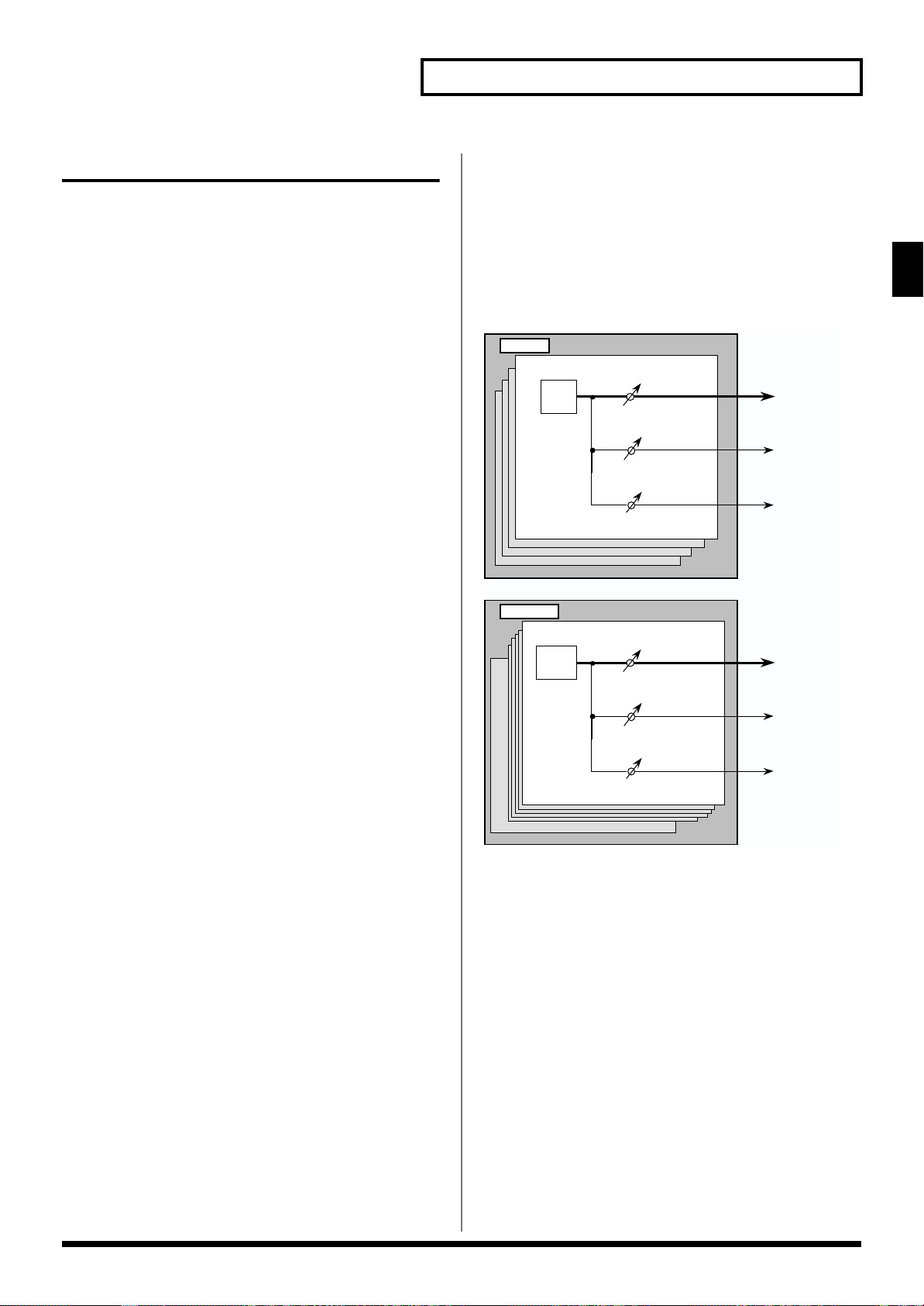
Overview of the Fantom
Chorus
Reverb
TONE
Multi-Effects
Patch
Chorus
Reverb
RHYTHM
TONE
Multi-Effects
Rhythm Set
A0
C8
About the Onboard Effects
Effect Types
The Fantom has three built-in effect units, and you can
independently edit each unit’s settings.
Multi-Effects
The multi-effects are multi-purpose effects that completely change
the sound type by changing the sound itself. Contained are 90
different effects types; select and use the type that suits your aims. In
addition to effects types composed of simple effects such as
Distortion, Flanger, and other such effects, you can also set up a
wide variety of other effects, even connecting effects in series or in
parallel. Furthermore, while chorus and reverb can be found among
the multi-effects types, the following chorus and reverb are handled
with a different system.
Chorus
Chorus adds depth and spaciousness to the sound. You can select
whether to use this as a chorus effect or a delay effect.
Reverb
Reverb adds the reverberation characteristics of halls or
auditoriums. Four different types are offered, so you can select and
use the type that suits your purpose.
How Effects Units Work in Different Modes
In Patch Mode
The multi-effects, chorus and reverb effects can be set up
individually for each patch/rhythm set. Adjusting the signal level to
be sent to each effects unit (Send Level) provides control over the
effect intensity that’s applied to each tone.
fig.01-07
Overview of the Fantom
23
Page 24
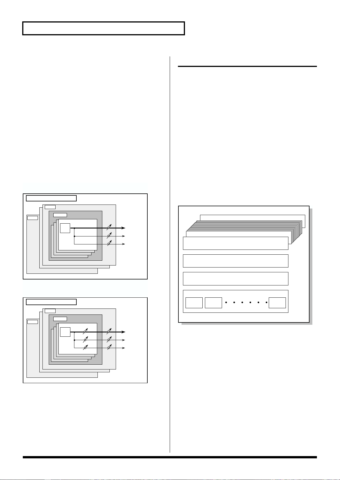
Overview of the Fantom
In the Performance Mode or
Multitimbre Mode
The multi-effects, chorus and reverb effects can be set individually
for each performance and multitimbre. The intensity of each effect
will be set for each part (Fig. 1), but the Send Level setting for each
tone can also influence effect intensity (Fig. 2).
When you apply effects in Performance mode or Multitimbre mode,
the effect settings of the patch or rhythm set assigned to each part
will be ignored, and the effect settings of the performance or
multitimbre will be used. Thus, the effects for the same patch or
rhythm set may differ when played in Patch mode and in
Performance/Multitimbre mode. However, depending on the
settings, you can have effect settings for a patch or rhythm set
assigned to a part applied to the entire performance/multitimbre (p.
173, p. 174). In addition, when using the multi-effects settings of a
performance or multitimbre, you can use three different multi-effects
simultaneously, depending on the effect type (p. 175).
fig.01-08.e
Fig.1 – When Output Assign parameter is set to “MFX”
(the output settings for Tone are ignored)
Performance/Multitimbre
Part 1
Part16
Patch
TONE
Multi-Effects
Chorus
Reverb
About the Sequencer
A sequencer records keyboard performance and controller
movements as MIDI messages (sequencer data). As the data plays
back, the recorded MIDI messages are sent to a sound generator
which will produce the required sounds. The sequencer actually
plays instruments instead of the musician, and since it can record a
musical performance, it is a tape recorder as well.
But in reality a sequencer doesn’t record sound, but actually the
steps that cause the sound generator to produce sound, so it offers
several advantages. Sound quality is always excellent, the equivalent
of first-generation tape, no matter how many times the data plays
back; tempo changes have no effect on pitch; detailed editing is
possible, etc.
What Is a Song?
For the Fantom, musical performance data for one song or
composition is referred to as a song. A song combines sequencer
data recorded on Phrase tracks 1–16, a Tempo track, a Beat track and
a Pattern track, as discussed below.
fig.01-09.e
Song
Phrase track 16
Phrase track 2
Phrase track 1
Fig.2 – When Output Assign parameter is set to “PAT”
(the output settings for Tone are valid)
Performance/Multitimbre
Part 1
Part16
Patch
TONE
Multi-Effects
Chorus
Reverb
Tempo track
Beat track
Pattern track
Pattern1Pattern
2
Pattern
100
What Is a Track?
Each section of a song which stores musical performance data is
called a track.
Phrase Tracks 1–16
Phrase tracks record the musical performance. Each Phrase track
records musical performance data for 16 MIDI channels. Totally, up
to 16 tracks x 16 MIDI channels of data can be recorded. It’s helpful if
you’ve made decision prior to recording such as recording melody
on Phrase track 1, bass on Phrase track 2, drums on Phrase track 10,
and accompaniment on the remaining Phrase tracks.
24
Page 25
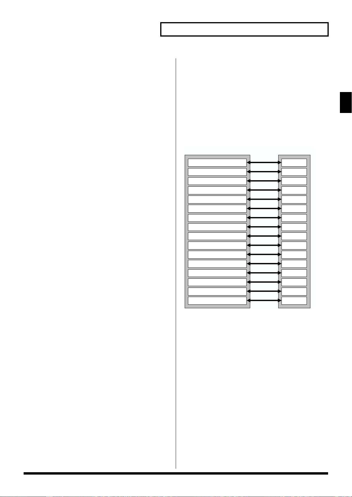
Overview of the Fantom
Tempo Track
The Tempo track records tempo changes of a song over time. It can
be used for tempo changes during a song. If a song has the same
tempo from beginning to end, the Tempo track can be ignored.
When a song is first recorded on the Fantom, a tempo setting at the
time of recording will be stored at the beginning of the Tempo track.
Therefore when song playback starts from the beginning, the song
will always play back at this initial tempo.
Thus playback tempo is determined by the Tempo track setting. If
you modify the tempo during playback, the overall tempo of the
song will be controlled by the setting you make.
Beat Track
The Beat track records the time signature of each measure of a song.
Set the Beat track when recording a new song, or when you want to
change time signature during a song.
Pattern Track
You can also use the Pattern track to record musical passages,
separately from the Phrase tracks. Musical data in the Pattern track is
regarded as separate Patterns. Up to 100 Patterns can be created, and
each Pattern can contain data for 16 MIDI channels, as with Phrase
tracks.
Patterns can be assigned to a Phrase track, so if you are using
repetitive phrases such as drums and bass, it is convenient to record
each musical phrase in a pattern, and then use the MICROSCOPE
screen to assign the pattern to the track (p. 134). In this case, the
Phrase track contains only the Pattern Call numbers that refer to the
desired Pattern, and not the actual Pattern data. Therefore the same
Pattern can be used any number of times with a negligible increase
in memory used.
The RPS function (p. 159) for immediate playback also applies to
Patterns. Patterns are therefore convenient for live performance, if
you’ve recorded necessary sequencer data as Patterns and take them
to the gig.
Patterns also make fine scratch-pads for musical ideas.
How Phrase Tracks, Parts and MIDI Channels Interact
When the sound generator is in Multitimbre mode, you will need to
be aware of how the phrase tracks, parts, and MIDI channels
correspond to one another. Otherwise, you may not hear the sounds
you expect, or song editing may be more difficult than it should be.
For this reason, we recommend that you always maintain the direct
numerical correspondence between Phrase tracks 1–16, parts 1–16,
and MIDI channels 1–16. These are the settings that will be in effect
when the power is turned on, or after you perform the Song
Initialize operation (p. 127).
fig.01-10.e
Sequencer
Phrase track 1
Phrase track 2
Phrase track 3
Phrase track 4
Phrase track 5
Phrase track 6
Phrase track 7
Phrase track 8
Phrase track 9
Phrase track 10
Phrase track 11
Phrase track 12
Phrase track 13
Phrase track 14
Phrase track 15
Phrase track 16
Ch 1
Ch 2
Ch 3
Ch 4
Ch 5
Ch 6
Ch 7
Ch 8
Ch 9
Ch 10
Ch 11
Ch 12
Ch 13
Ch 14
Ch 15
Ch 16
Sound Generator
Part 1
Part 2
Part 3
Part 4
Part 5
Part 6
Part 7
Part 8
Part 9
Part 10
Part 11
Part 12
Part 13
Part 14
Part 15
Part 16
Overview of the Fantom
Songs and the Sound Generator Mode
The Fantom’s sequencer can be used at any time, regardless of the
mode of the sound generator (Patch/Multitimbre/Performance).
Normally, when recording or playing back a song, you will put the
sound generator in Multitimbre mode. The reason for this is that in
this mode, only the sound of the specified MIDI channel will be
heard when you record while playing the keyboard of the Fantom,
and that when the song is played back, the parts can independently
play up to 16 different sounds. Thus, this mode is suitable for
recording and playing back a song that uses an ensemble of multiple
instruments, such as drums, bass, and piano.
If you wish to record your playing using a layered/split
performance, set the sound generator to Performance mode.
If you wish to record your playing using a single sound, you can set
the sound generator to Patch mode.
25
Page 26
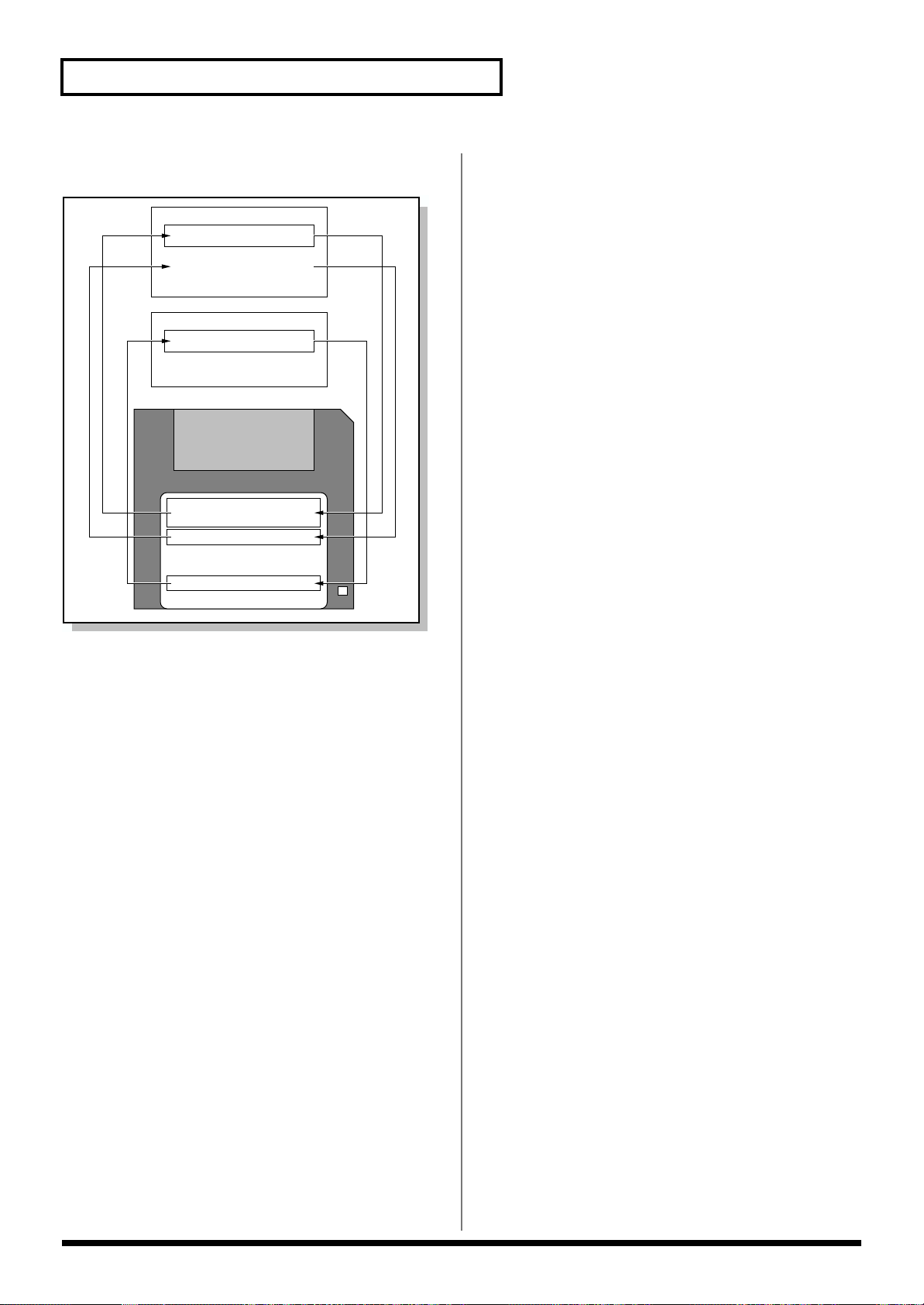
Overview of the Fantom
Positions for Storing a Song
fig.01-11.e
Load Save
Sequencer Section
Internal Memory
Sound Generator Section
User Memory
Disk
Song file
Standard MIDI file
Chain file
Data file
Disk
When keeping a recorded or edited song in internal memory, save it
to disk as a song file. Up to 99 songs can be saved to a single disk.
A disk can contain five file types. The three-letter symbol shown in
parentheses ( ) is a file name extension that distinguishes the
different file types.
Song File (.SVQ)
This file is a song created on the Fantom. It is called an MRC Pro
song. Other MRC Pro songs include those created on the XP-60/80.
Standard MIDI File (.MID)
Standard MIDI File is a standard file format that allows sequencer
data to be exchanged between most musical applications. Fantom
files can be saved as Standard MIDI Files. This also allows you to
play back commercially available music data (GM scores) that is
compatible with the GM/GM2 system.
Chain File (.SVC)
Chain Play is a function that successively plays back songs stored on
the disk, in the specified order.
Data File (.SVD)
This file contains Sound Generator and System settings.
Internal Memory
The sequencer has an area called internal memory that can
temporarily store one song. So we call this temporary song Internal
Song.
To play back a song saved to a disk with the Fantom, it doesn’t have
to be loaded into internal memory. Only when you’re going to
record a song or edit a song saved to disk, do you have to load it into
internal memory. Since only one song can be worked on during
recording or editing, all the internal memory has to do is store one
song (about 120,000 notes).
The song in internal memory is volatile and will be lost when the
power is turned off. To keep a song, you must save it to disk.
26
Page 27
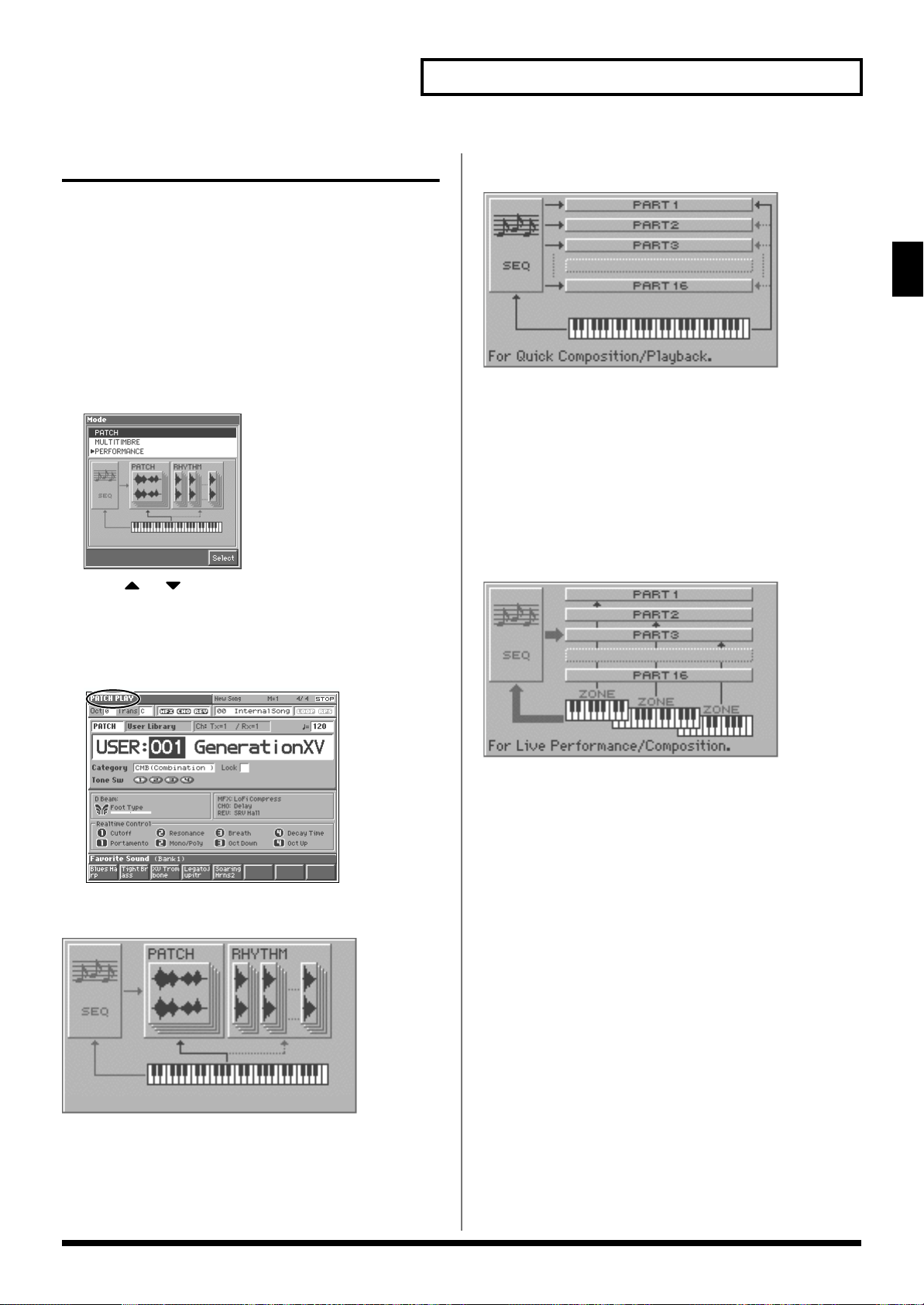
Overview of the Fantom
Basic Operation of the Fantom
Switching the Sound Generator Mode ([MODE])
The Fantom has three sound generating modes: Patch mode,
Multitimbre mode, and Performance mode. You can select the sound
generating mode (state) that is most appropriate for how you are
playing the Fantom.
Use the following procedure to switch between these modes.
1. Press [MODE].
The Mode window appears.
fig.01-12_50
2. Press or to select the desired mode, and then press
[8 (Select)].
When you select a mode, the PLAY screen of the corresponding
mode appears. In each mode, the upper left of the PLAY screen
will indicate the mode.
fig.01-13
Multitimbre Mode
fig.01-15
Overview of the Fantom
This mode is suitable when you are using the sequencer to create a
song, or when playing song data. When creating songs or playing
song data, a different MIDI channel is assigned for each patch used
in a part. Such a set of sounds selected for each part to play is called
a multitimbre.
The keyboard controller section and the sound generator section are
connected by a single MIDI channel (the receive channel of the
current part).
Performance Mode
fig.01-16
Patch Mode
fig.01-14
This mode is used to play individual sounds (patches or rhythm
sets) from the keyboard. If a rhythm set is selected, you can play
percussion instruments from the keyboard.
The keyboard controller section and the sound generator section are
connected by a single MIDI channel (the patch receive channel).
This mode allows you to combine multiple sounds (patches or
rhythm sets) to create complex setups, or to use the Fantom as a
master keyboard. You can play patches together (Layer) or divide
the keyboard into two regions and play different patches in each
region (Split).
The keyboard controller section and sound generator section are
connected according to the zone settings.
27
Page 28

Overview of the Fantom
Switching Screens from the Menu ([MENU])
The Fantom has a variety of screens and windows in which its
numerous functions can be executed, and you can move between
these screens as desired.
Use the following procedure to access the desired screen or window.
1. Press [MENU].
The Menu window appears.
fig.01-17_50
2. Press or to select the desired screen/window, and
then press [8 (Select)].
The screen/window for the desired function appears.
The screens/windows that can be selected from the Menu
window will depend on the mode of the sound generator.
Window
The somewhat smaller screens that appear temporarily on top
of the normal screens are called windows. Various types of
windows appears according to the situation. Some display lists,
others allow you to make settings, and still others ask you to
confirm an operation.
fig.01-17a.e
Viewing a List of Patches or Other Data ([LIST])
The Fantom can display sound lists and favorite lists. You can select
and audition patches from these lists, and register your own favorite
patches.
Use the following procedure to display these lists.
1. Use [CURSOR] to move the cursor to the object (e.g., patch
number) for which you wish to view a list.
2. Press [LIST].
The desired list window appears, according to the cursor
location.
fig.01-18_50
About the [1]–[8] Buttons
In the PLAY screen, the eight [1]–[8] buttons located below the
display allow you to select/register your favorite patches or
performances, and the lower area of the display will show the names
of the sounds that are registered as favorite sounds.
In other screens, these buttons execute various functions, and their
operation will differ depending on the screen.
fig.01-19
Window
Press [EXIT] to close the window. Some windows will close
automatically when an operation is performed.
28
Page 29
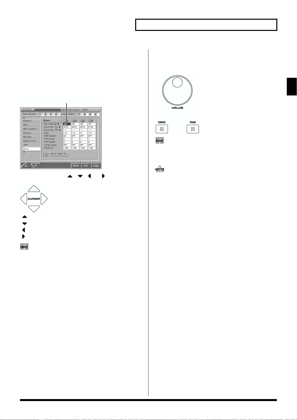
Overview of the Fantom
Moving the Cursor
A single screen or window displays multiple parameters or items for
selection. To edit the setting of a parameter, move the cursor to the
value of that parameter. To select an item, move the cursor to that
item. The cursor is a black rectangle, and the parameter value or item
you select with the cursor will be highlighted (displayed in inverse
video).
fig.01-19a.e
Cursor
Move the cursor with the , , and (cursor buttons).
fig.01-20
Modifying a Value
To modify the value, use the VALUE dial or the [INC]/[DEC]
buttons.
fig.01-21
In each screen of the Fantom, you can use the cursor to move the
area displayed as black characters on white background, and
modify its value.
Each parameter has its own range of possible values, so you
cannot set any value smaller than the minimum value or greater
than the maximum value.
Overview of the Fantom
: moves the cursor up.
: moves the cursor down.
: moves the cursor to the left.
: moves the cursor to the right.
• By holding down [SHIFT] and pressing a cursor button, you can
make the cursor location jump to the edge of the same block.
• By holding down [JUMP] and pressing a cursor button, you can
make the cursor location jump to another block.
• If you hold down one cursor button while you also press the
cursor button for the opposite direction, the cursor will move
more rapidly in the direction of the first-pressed cursor button.
VALUE Dial
Rotating the VALUE dial clockwise increases the value,
counterclockwise decreases the value. Holding down [SHIFT] as you
move the VALUE dial increases value increments so you can make
large value changes faster.
[INC] and [DEC]
Pressing [INC] increases the value, and [DEC] decreases it. Keep the
button pressed for continuous adjustment. For faster value increases,
keep [INC] pressed down and press [DEC]. For decreasing value
faster, keep [DEC] pressed down and press [INC].
If you press [INC] or [DEC] while holding down [SHIFT], the value
increments will get bigger.
29
Page 30
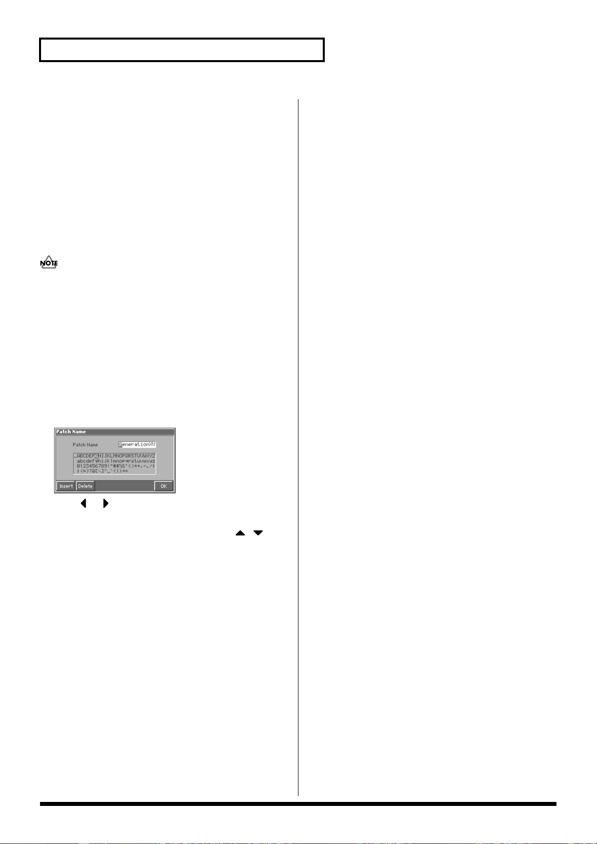
Overview of the Fantom
Assigning a Name
On the Fantom, you can assign names to each patch, rhythm set,
multitimbre, performance, Song, and Pattern. The procedure is the
same for any type of data.
1. Press [CURSOR] to move the cursor to the location where
you wish to input a character.
2. Turn the VALUE dial, or press [INC]/[DEC] to specify the
character.
Available characters/symbols are:
space, A–Z, a–z, 0–9, ! " # $ % & ’ ( ) * + , - . / : ; < = > ? @ [ \ ] ^ _
` { | } → ←
File names and volume label names may not contain lowercase
characters or certain symbols (" * + , . / : ; < = > ? [ \ ] | → ←).
Assigning a Name Using a Name
Window
You can use a Name window to assign a name. As the Name
window displays a list of characters that can be entered, you can
quickly select a desired character.
1. In a naming screen, move the cursor to the text input
location, and press [LIST].
The Name window appears.
fig.01-22_50
2. Press or to move the cursor to the location where you
wish to input a character.
3. Either turn the VALUE dial or use [INC], [DEC], , to
select the character that you wish to input.
To insert a space at the cursor location, press [3 (Insert)].
To delete the character at the cursor position, press [4 (Delete)].
4. Repeat steps 2 and 3 as necessary.
5. Press [8 (OK)] to finalize the name.
30
Page 31

Playing in Patch Mode
Indicates the current sound generating mode.
Displays the type of effect used.
Indicates the song file name.
Indicates the name of the currently selected song,
the measure location, the time signature, and the sequencer status.
Indicates the group of the selected patch.
Patch/rhythm set select switch
Determines whether you will be selecting patches or rhythm sets.
Indicates the MIDI transmit channel (Tx Ch)
and receive channel (Rx Ch).
This indicates the function that is assigned to the D Beam controller,
and the response status of the D Beam controller.
Indicates/sets the tempo at which the song,
Arpeggio or rhythm pattern is played.
Indicates the tone
On/Off status.
Indicates/selects the
patch category.
Selects whether the patch
category will be locked.
Indicates/selects the group, number,
and name of the selected patch.
Indicates the functions that are assigned to each
realtime controller knob (●) and button (■).
The value will be displayed when you turn the knob.
Indicates the names of the patches or
rhythm sets that can be selected by [1]–[8].
Sets the Octave Shift (Oct)
and the Transpose (Trans).
Switches multi-effects (MFX),
chorus (CHO),
and reverb (REV) on and off.
Turns the RPS function on/off (RPS).
Turns Loop Play on/off (LOOP).
Patch mode is the mode in which you can play the keyboard using a
single sound (patch or rhythm set). If a rhythm set is selected, you
can play percussion instruments from the keyboard.
About the PATCH PLAY Screen
Displaying PATCH PLAY Screen
To access the PATCH PLAY screen, use the following procedure.
1. Press [MODE].
The Mode window appears.
fig.01-12_50
2. Press or to select a “PATCH,” and then press [8
(Select)].
You will enter Patch mode, and the PATCH PLAY screen
appears.
fig.PATCH_50
Functions in the PATCH PLAY Screen
fig.02-01.e
Playing in Patch Mode
31
Page 32

Playing in Patch Mode
Selecting a Patch
The Fantom has six patch groups, including the User group and
Preset groups A–E and GM, with each group storing 128 patches
(256 in GM), for a total of 1,024 patches. What’s more, you can
further expand your options by installing up to three optional Wave
Expansion Boards (one SR-JV80, two SRX series), enabling you to
select from a huge assortment of available patches.
USER
This is the group inside the Fantom which can be rewritten. patches
you yourself create can be stored in this group. The Fantom includes
128 preset patches.
PR-A–E (Preset A–E)
This is the group inside the Fantom which cannot be rewritten.
However you may modify the settings of the currently selected
patch, and then store the modified patch in User memory. Banks A–
E already contain 128 prepared patches each, for a total of 640
patches.
GM (GM2)
This is an internal group of patches compatible with General MIDI 2,
a system of MIDI function specifications designed to transcend
differences between makers and types of devices; these patches
cannot be overwritten. Furthermore, settings of currently selected
patches from this group cannot be changed. The Fantom includes
256 preset patches.
XP-A–C (Wave Expansion Boards installed in
EXP-A–C Slots)
These are groups used when using patches from Wave Expansion
Boards installed in the EXP A–C slots, and cannot be rewritten.
However you may modify the settings of the currently selected
patch, and then store the modified patch in User memory. The
number of onboard patches depends on the specific Wave Expansion
Boards installed.
1. Access the PATCH PLAY screen (p. 31).
fig.02-02.e
Patch group
Patch number
2. Make sure that the patch/rhythm set select switch is set to
“PATCH.”
If it is set to “RHYTHM,” turn the VALUE dial or press [DEC] to
change it to “PATCH.”
3. Press [CURSOR] to move the cursor to the patch group.
4. Turn the VALUE dial, or press [INC]/[DEC] to select a patch
group.
USER: User
PR-A–E: Preset A–E
GM: GM (GM2)
XP-A–C: Wave Expansion Boards installed in EXP-A–C Slots
5. Press [CURSOR] to move the cursor to the patch number.
6. Turn the VALUE dial, or press [INC]/[DEC] to select a patch
number.
XP-A–C patches can be selected only if a Wave Expansion Board
is installed in the corresponding slot.
XP-A (EXP A slot): SR-JV80 series (sold separately)
XP-B, C (EXP B, C slots): SRX series (sold separately)
32
Page 33

Selecting Favorite Patches (Favorite Sound)
You can bring together your favorite and most frequently used
patches in one place by registering them in the Favorite sound. By
using this function, you can rapidly select favorite patches from
internal memory or a Wave Expansion Board.
If a patch stored in a Wave Expansion Board has been registered
as a Favorite Sound, it cannot be selected unless the
corresponding wave expansion board is installed.
Playing in Patch Mode
By pressing [7 (Prevu)] you can audition the sound of the patch,
by means of a phrase preselected as being suitable for that
particular type (category) of patch (Phrase Preview).
4. To switch banks, press to move the cursor to the “Bank
1–8” tab, and press or to select the desired bank.
5. After switching the bank, press to move the cursor within
the list, and press or to select the patch.
6. When you press [8 (Select)], the patch will be selected, and
the Favorite List window will close.
Playing in Patch Mode
For instructions on how to register to the Favorite Sounds, refer
to “Registering a Favorite Patch (Favorite Sound)” (p. 46).
Selecting from [1]–[8]
1. Access the PATCH PLAY screen (p. 31).
2. Press [1]–[8] to select a patch.
fig.02-03.e
Press [1]–[8] to select a patch
3. To switch the favorite sound bank, hold down [JUMP] and
press [1]–[8].
Selecting from the Favorite List Window
1. In the PATCH PLAY screen, make sure that the cursor is
located at the patch group or patch number.
2. While holding down [SHIFT], press [LIST]
The Favorite List window appears.
fig.02-04_50
Selecting Patches from the List
You can display a list of patches and select a patch from that list.
1. In the PATCH PLAY screen, make sure that the cursor is
located at the patch group or patch number.
2. Press [LIST].
The Patch List window appears.
fig.01-18_50
3. Press or to choose the patch.
4. To switch patch groups, press to move the cursor to the
patch group tab, and press or to select the patch
group.
5. After switching the patch group, press to move the
cursor within the list, and press or to select the
patch.
6. Press [EXIT] to close the Patch List window.
In the Patch List window, you can press [7 (Ctg)] to add a check
mark (✔) and switch to viewing a list organized by category.
Here you can select patches by category (p. 34).
3. Press or to choose the patch.
33
Page 34

Playing in Patch Mode
Auditioning Patches (Phrase Preview)
The Fantom allows you to preview patches by hearing a phrase
appropriate for each type of patch.
1. Access the Patch List window (p. 33).
fig.01-18_50
2. Press and hold [8 (Prevu)].
The patch selected in the Patch List window will be sounded.
3. Release your finger from [8 (Prevu)], and the phrase will stop
playing.
• If you wish to change the phrase that is played by Phrase
Preview, you can edit the Patch Category parameter (PATCH/
General) (p. 47).
• If you wish to change how the phrase is played by Phrase
Preview, you can edit the Preview Mode parameter (SYSTEM/
General) (p. 185).
5. Press to move the cursor to “Lock,” and turn the VALUE
dial or press [INC] to add a check mark (✔).
fig.02-05
Now you can select patches within the category you selected in
step 4.
6. Use [CURSOR] to move the cursor to the patch group or
patch number, and turn the VALUE dial or use [INC]/[DEC] to
select the patch.
When the cursor is located at the Patch group, you can select the
group. When the cursor is located at the Patch number, you can
specify the number.
Selecting from the Patch List Window
1. Access the Patch List window (p. 33).
fig.01-18_50
Selecting Patches by Category (Patch Finder)
The Fantom provides a “Patch Search function” (Patch Finder)
which allows you to specify a type (category) of patch so that you
can quickly find the desired patch. There are a total of 38 categories.
1. Access the PATCH PLAY screen (p. 31).
2. Make sure that the patch/rhythm set select switch is set to
“PATCH.”
If it is set to “RHYTHM,” turn the VALUE dial or press [DEC] to
change it to “PATCH.”
3. Use [CURSOR] to move the cursor to “Category.”
4. Turn the VALUE dial, or press [INC]/[DEC] to select the
desired category.
2. Press [7 (Ctg)] to add a check mark (✔).
The display will show a list of patches organized by category.
fig.02-06_50
3. Press to move the cursor to the category tab, and
press or to select the category.
A list of the patches in the selected category will be displayed.
4. Press to move the cursor in the list, and
press or to select a patch.
34
By pressing [8 (Prevu)] you can audition the sound of the patch
being played by a phrase suitable for the corresponding type
(category) of patch (Phrase Preview).
Page 35

Playing in Patch Mode
5. Press [EXIT] to close the Patch List window.
The following categories can be selected.
Category Contents
- - - No Assign No assign
PNO AC.Piano Acoustic Piano
EP EL.Piano Electric Piano
KEY Keyboards Other Keyboards
(Clav, Harpsichord etc.)
BEL Bell Bell, Bell Pad
MLT Mallet Mallet
ORG Organ Electric and Church Organ
ACD Accordion Accordion
HRM Harmonica Harmonica, Blues Harp
AGT AC.Guitar Acoustic Guitar
EGT EL.Guitar Electric Guitar
DGT DIST.Guitar Distortion Guitar
BS Bass Acoustic & Electric Bass
SBS Synth Bass Synth Bass
STR Strings Strings
ORC Orchestra Orchestra Ensemble
WND Wind Winds (Oboe, Clarinet etc.)
FLT Flute Flute, Piccolo
BRS AC.Brass Acoustic Brass
SBR Synth Brass Synth Brass
SAX Sax Sax
HLD Hard Lead Hard Synth Lead
SLD Soft Lead Soft Synth Lead
HIT Hit&Stab Orchestra Hit, Hit
TEK Techno Synth Techno Synth
PLS Pulsating Pulsating Synth
FX Synth FX Synth FX (Noise etc.)
SYN Other Synth Poly Synth
BPD Bright Pad Bright Pad Synth
SPD Soft Pad Soft Pad Synth
VOX Vox Vox, Choir
PLK Plucked Plucked (Harp etc.)
ETH Ethnic Other Ethnic
FRT Fretted Fretted Inst (Mandolin etc.)
PRC Percussion Percussion
SFX Sound FX Sound FX
BTS Beat&Groove Beat and Groove
DRM Drums Drum Set
CMB Combination Other patches which use Split and
Layer
Transposing the Keyboard in Octave Units (Octave Shift)
The Octave Shift function transposes the pitch of the keyboard in 1
octave units (-3– +3 octaves).
For playing a bass part more easily using your right hand, transpose
the keyboard down by 1 or 2 octaves.
1. Access the PATCH PLAY screen (p. 31).
2. Use [CURSOR] to move the cursor to “Oct.”
fig.02-07
3. Either turn the VALUE dial or use [INC]/[DEC] to specify the
amount of pitch shift (-3–+3 octaves).
There is a single Octave Shift setting (Setup parameter) for the
entire Fantom. The changed setting will be remembered even if
you switch patches or performances.
If you assign “OCT UP/DOWN” as a function to be controlled
by the realtime control buttons ([ ]–[ ]), you can easily
change the Octave Shift by pressing these buttons.
Playing in Patch Mode
35
Page 36

Playing in Patch Mode
Transposing the Keyboard in Semitone Steps (Transpose)
Transpose changes keyboard pitch in units of semitones.
This function is useful when you play transposed instruments such
as trumpet or clarinet following a printed score.
1. Access the PATCH PLAY screen (p. 31).
2. Use [CURSOR] to move the cursor to “Trans.”
fig.02-08
3. Either turn the VALUE dial or use [INC]/[DEC] to adjust the
Transpose setting (G–F#: -5–+6 semitones).
Selecting the Tones That Will Sound (Tone On/Off)
Since a patch is a combination of up to four tones, you can switch
unwanted (tones out of the four) off and get just the sound of a
specific tone.
1. Access the PATCH PLAY screen (p. 31).
2. Press [MENU] to open the Menu window.
3. Press or to select a “Patch Edit,” and then press [8
(Select)].
The Patch Edit screen appears.
4. Use [CURSOR] to move the cursor to “Tone Switch.”
fig.02-09
There is a single Transpose setting (Setup parameter) for the
entire Fantom. The changed setting will be remembered even if
you switch patches or performances.
If you assign “TRNS UP/DOWN” as a function to be controlled
by the realtime control buttons ([ ]–[ ]), you can easily
change the Transpose by pressing these buttons.
5. Turn the VALUE dial or press [INC]/[DEC] to turn each tone
on/off. From the left, these are Tone Switches 1–4.
Assigning a check mark (✔) will turn the tone on, and
removing the check mark will turn it off.
• If you want just one or two tones to sound in a patch, turn the
others off and store that setting on a patch. This cuts
nonessential use of the Fantom’s simultaneous voices.
• By holding down [JUMP] and pressing [1]–[4], you can switch a
tone on/off.
36
Page 37

Playing in Patch Mode
Playing Single Notes (Mono)
When using a patch for a naturally monophonic instrument such as
sax or flute, it is effective to play in mono.
1. Access the PATCH PLAY screen (p. 31).
2. Press [MENU] to open the Menu window.
3. Press or to select a “Patch Edit,” and then press [8
(Select)].
The Patch Edit screen appears.
4. Press [1 (▲)] or [2 (▼)] to select the “General” tab.
A screen like the one shown below appears.
fig.03-01_50
5. Use [CURSOR] to move the cursor to “Mono/Poly.”
6. Turn the VALUE dial or press [DEC] to select “MONO.”
Now you can play in mono mode.
If you assign “MONO/POLY” as a function to be controlled by
the realtime control buttons ([ ]–[ ]), you can easily switch
between mono/poly by pressing a button.
Creating Smooth Pitch Changes (Portamento)
Portamento is an effect which smoothly changes the pitch from the
first-played key to the next-played key. By applying portamento
when Mono mode is selected (see the preceding item), you can
simulate performance effects such as slurring on a violin.
1. Access the PATCH PLAY screen (p. 31).
2. Press [MENU] to open the Menu window.
3. Press or to select a “Patch Edit,” and then press [8
(Select)].
The Patch Edit screen appears.
4. Press [1 (▲)] or [2 (▼)] to select the “General” tab.
A screen like the one shown below appears.
fig.03-01_50
5. Use [CURSOR] to move the cursor to “Portamento Switch.”
6. Turn the VALUE dial or press [INC] to select “ON.”
You’re ready to play portamento.
7. When you want to change the portamento setting, edit the
following parameters in the screen of step 4.
Portamento Mode, Portamento Type, Portamento Start,
Portamento Time
Playing in Patch Mode
See (p. 48) for each parameter’s functions.
8. Turn the VALUE dial or press [INC]/[DEC] to get the value
you want.
9. Press [EXIT] to return to the PATCH PLAY screen and play.
If you assign “CC65 (Portamento)” as a function to be controlled
by the realtime control buttons ([ ]–[ ]), you can use a
button to easily turn portamento on/off.
37
Page 38

Playing in Patch Mode
Playing Arpeggios (Arpeggiator)
The Arpeggiator provides for the play of the various notes in chords.
With the Arpeggiator, you can play arpeggios that use the
component notes of a chord, just by pressing the chord. In addition
to normal arpeggios, you can also accurately simulate rhythm guitar
or strumming techniques depending on the Arpeggiator settings.
The Arpeggiator can in fact be used as a handy automatic arranger.
1. Access the PATCH PLAY screen (p. 31).
2. Press [ARPEGGIO] to turn the Arpeggiator on.
3. Play a chord on the keyboard.
The Fantom will play an arpeggio, according to the notes
forming the chord you have just voiced.
4. To finish playing arpeggios, press [ARPEGGIO] again so the
indicator turns off.
Holding an Arpeggio
By using the following procedure, you can produce arpeggios even
without continuing to press the keyboard.
1. Hold down [SHIFT] and press [ARPEGGIO].
The [ARPEGGIO] indicator will begin blinking.
2. Play a chord.
3. If you play a different chord or notes while the arpeggio is
being held, the arpeggio will change accordingly.
4. To cancel Arpeggio Hold, hold down [SHIFT] and press
[ARPEGGIO] simultaneously once again.
Simulating a Rhythm Guitar
You can simulate a rhythm guitar by following the procedure below.
1. Access the PATCH PLAY screen, and select a guitar patch
(p. 31).
2. Hold down [JUMP] and press [ARPEGGIO].
The Arpeggio window appears.
fig.02-12_50
3. Use [CURSOR] to move the cursor to “Style.”
4. Either turn the VALUE dial or use [INC]/[DEC] to select the
one you want from “AG CUTTING PHR.”
5. Press [ARPEGGIO] to turn the Arpeggiator on.
6. Play a chord on the keyboard.
Guitar strumming will begin according to the notes in the chord
you pressed.
If you assign Cutoff (CC74) or Resonance (CC71) to the realtime
control knobs (p. 163) and turn these knobs while you play, you
can apply a wah effect to the guitar strumming.
When Using a Hold Pedal
If you play an arpeggio while pressing the hold pedal, the arpeggio
will continue to be played even if you release the chord.
1. Connect an optional pedal switch (DP-2, DP-6, etc.) to the
HOLD PEDAL jack.
2. Press [ARPEGGIO] to turn the Arpeggiator on.
3. Play a chord while pressing the hold pedal.
4. If you play a different chord or notes while the arpeggio is
being held, the arpeggio will change accordingly.
38
Page 39

Playing in Patch Mode
Using an External MIDI Keyboard to Play Arpeggios
You can also use the keyboard of an external MIDI instrument to
play arpeggios.
1. Use a MIDI cable to connect the Fantom’s MIDI IN connector
to the MIDI OUT connector of the external MIDI keyboard.
2. Access the PATCH PLAY screen (p. 31).
3. Press [ARPEGGIO] to turn the Arpeggiator on.
4. Press [MENU] to open the Menu window.
5. Press or to select a “System Edit,” and then press
[8 (Select)].
The System Edit screen appears.
6. Press [1 (▲)] or [2 (▼)] to select the “MIDI” tab.
A screen like the one shown below appears.
fig.02-13_50
7. Use [CURSOR] to move the cursor to “Remote Keyboard
Sw.”
8. Turn the VALUE dial or press [INC] to select “ON.”
9. Play your external MIDI keyboard.
Making Arpeggiator Settings
1. Hold down [JUMP] and press [ARPEGGIO].
The Arpeggio window appears.
fig.02-12_50
Playing in Patch Mode
In this window you can set the following arpeggiator
parameters.
Switch: Switches the Arpeggiator on/off.
Hold: Switch between Hold On/Hold Off for the Arpeggiator
performance.
Style: Specify the basic performance style of the arpeggio.
Variation: Select the variation (performance pattern) for each
arpeggio style.
Motif: Specify the order in which the component notes of the
chord will be sounded.
Key Trigger: Specify the timing at which the arpeggio is to
begin playing.
Tempo (=SEQ): Specify the tempo of an arpeggio.
Accent Rate: Vary the strength and note length of the accents to
modify the rhythmic feel (groove) of the performance.
Shuffle Rate: Create shuffle rhythms by modifying the timing at
which notes are sounded.
Shuffle Resolution: Specify the timing of the notes in terms of
note value.
Velocity: Specify the note strength of the keys you play.
Octave Range: Specify the range of the arpeggio performance,
in octave units.
In arpeggio settings, the Style (Arpeggio Style) is particularly
important. The playback pattern of the arpeggio is determined
mainly by this selection.
For details regarding each parameter, refer to “Arpeggiator
Settings (Arpeggio)” (p. 51).
2. Press [CURSOR] to move the cursor to each parameter, and
either turn the VALUE dial or press [INC] or [DEC] to make
the setting.
3. Press [8 (Close)] to close the Arpeggio window.
Arpeggiator settings can be saved with each patch as part of the
patch settings. This means that you can create patches that
contain the most effective settings.
39
Page 40

Playing in Patch Mode
Playing Percussion Instruments
In Patch mode, you can play percussion instruments from the
keyboard by selecting a rhythm set. As the rhythm tone assigned to
each key varies by the rhythm set selected, you can play a wide
range of percussion instruments.
Selecting a Rhythm Set
The Fantom has three rhythm set groups, including the User group,
Preset group and GM group, with 16 rhythm sets in the User group,
16 rhythm sets in Preset group, and 9 rhythm sets in GM group, for a
total of 41 rhythm sets. What’s more, you can further expand your
options by installing up to three optional Wave Expansion Boards
(one SR-JV80, two SRX series), enabling you to select from a large
selection of rhythm sets.
USER
This is the group inside the Fantom which can be rewritten. rhythm
sets you yourself create can be stored in this group. The Fantom
includes 16 preset rhythm sets.
PRST (Preset)
This is the group inside the Fantom which can be rewritten.
However, you can modify the settings of the currently selected
rhythm set, and then save the modified settings in User memory.
The Fantom contains 16 preset rhythm sets.
1. Access the PATCH PLAY screen (p. 31).
2. Use [CURSOR] to move the cursor to “PATCH.”
fig.02-14
3. Turn the VALUE dial, or press [INC] to select “RHYTHM.”
A screen like the following appears, allowing you to select a
rhythm set.
fig.02-15.e
Rhythm set group
Rhythm set number
GM (GM2)
This is an internal group of rhythm sets compatible with General
MIDI 2, a system of MIDI function specifications designed to
transcend differences between makers and types of devices; these
rhythm sets cannot be overwritten. Furthermore, settings of
currently selected rhythm sets from this group cannot be changed.
The Fantom includes nine preset rhythm sets.
XP-A–C (Wave Expansion Boards installed in
EXP-A–C Slots)
These groups are for when using rhythm sets from a Wave
Expansion Board installed in slots EXP A–C, and cannot be
rewritten. However, you can modify the settings of the currently
selected rhythm set, and then save the modified settings in User
memory. The number of onboard rhythm sets depends on the
specific Wave Expansion Boards installed.
A Rhythm Set XP-A–C cannot be accessed if the Wave
Expansion Board it belongs to has not been installed.
XP-A (EXP A slot): SR-JV80 series (sold separately)
XP-B, C (EXP B, C slots): SRX series (sold separately)
4. Press [CURSOR] to move the cursor to the rhythm set
group.
5. Turn the VALUE dial or press [INC]/[DEC] to select the
rhythm set group.
USER: User
PRST: Preset
GM: Preset GM (GM2)
XP-A–C: Wave Expansion Boards installed in EXP-A–C Slots
6. Press [CURSOR] to move the cursor to the rhythm set
number.
7. Turn the VALUE dial or press [INC]/[DEC] to select the
rhythm set number.
You can select favorite rhythm sets in the same way as when
selecting patches. For details on the procedure, refer to
“Selecting Favorite Patches (Favorite Sound)” (p. 33).
40
Page 41

Playing in Patch Mode
Playing a Rhythm Set
1. Select the rhythm set that you wish to play.
2. Press a key on the keyboard to play a percussion
instrument.
Below the rhythm set name, the screen shows the note name of
the key you pressed, and the name of the percussion instrument
(rhythm tone name) assigned to that key.
fig.02-16.e
Note name
Rhythm tone name
Playing Rhythm Patterns from the Keyboard
The Fantom contains various Rhythm patterns. Simply by pressing a
single key, you can play the Rhythm patterns.
1. Access the PATCH PLAY screen, and select a rhythm set (p.
40).
2. Press [RHYTHM] to make the indicator light.
3. Press a key to which a Rhythm pattern is assigned.
The Rhythm pattern assigned to the key you pressed will sound.
4. To stop playing Rhythm patterns, press [RHYTHM] once
again to make the indicator go dark.
Holding the Playback of a Rhythm Pattern
If you perform the following operation, you can play the Rhythm
pattern without having to continue holding down the key.
1. Hold down [SHIFT] and press [RHYTHM].
The [RHYTHM] indicator will begin blinking.
2. Press a key to which a Rhythm pattern is assigned.
3. If you press another key while Hold is in effect, the Rhythm
pattern will change accordingly.
4. To cancel Rhythm Pattern Hold, hold down [SHIFT] and
press [RHYTHM] simultaneously once again.
When Using a Hold Pedal
By holding down the Hold pedal while you play the Rhythm
pattern, you can make the Rhythm pattern continue sounding even
after you release the key.
1. Connect an optional pedal switch (DP-2, DP-6, etc.) to the
HOLD PEDAL jack.
2. Press [RHYTHM].
3. Hold down the Hold pedal, and press a key to which a
Rhythm pattern is assigned.
4. If you press another key while Hold is in effect, the Rhythm
pattern will change accordingly.
Making Rhythm Pattern Settings
1. Hold down [JUMP] and press [RHYTHM].
The Rhythm Pattern window appears.
fig.02-17_50
In this window you can set the following Rhythm pattern
parameters.
Switch: Switch Rhythm pattern playback on/off.
Hold: Switch between Hold On/Hold Off for the Rhythm
pattern playback.
Style: Specify the basic performance style of the Rhythm
pattern.
Key Trigger: Specify the timing at which the Rhythm pattern is
to begin playing.
Tempo (=SEQ): Specify the tempo of Rhythm pattern playback.
Accent Rate: Adjust the accent strength or note length to
modify the rhythm feel (groove) of the performance.
Shuffle Rate: Adjust the note timing to produce shuffle
rhythms.
Shuffle Resolution: Specify the timing of the notes in terms of a
note value.
Velocity: Specify the note strength for the keys you play.
Note Assign: Specify the keyboard note that will play the
Rhythm pattern.
In rhythm pattern parameters, the Style (Rhythm Pattern Style)
setting is particularly important. The playback pattern of the
rhythm is determined mainly by this selection.
For details regarding each parameter, refer to “Rhythm Pattern
Settings (Rhythm Ptn)” (p. 75).”
2. Press [CURSOR] to move the cursor to each parameter, and
either turn the VALUE dial or press [INC] or [DEC] to make
the setting.
3. Press [8 (Close)] to close the Rhythm Pattern window.
Rhythm pattern settings can be saved with each rhythm set as
part of the rhythm set settings. This allows you to create a
rhythm set that uses the most effective settings.
Playing in Patch Mode
41
Page 42

Creating a Patch
With the Fantom, you have total control over a wide variety of
settings. Each item that can be set is known as a parameter. When
you change the values of parameters, you are doing what is referred
to as Editing. This chapter explains the procedures used in creating
patches, and the functions of the patch parameters.
How to Make the Patch Settings
Start with an existing patch and edit it to create a new patch. Since a
patch is a combination of up to any four tones, you should listen to
how the individual tones sound before you edit.
Four Tips for Editing Patches
● Select a patch that is similar to the sound you wish to
create (p. 32).
It’s hard to create a new sound that’s exactly what you want if
you just select a patch and modify its parameters at random. It
makes sense to start with a patch whose sound is related to
what you have in mind.
● Decide which tones will sound (p. 36).
When creating a patch, it is important to decide which tones
you are going to use. In the Patch Edit screen, set Tone Switch
1–4 to specify whether each tone will sound (on), or not (off). It
is also important to turn off unused tones to avoid wasting
voices, unnecessarily reducing the number of simultaneous
notes you can play. Tones for which the Tone Switch displays a
check mark (✔) will sound.
● Check the Structure setting (p. 56).
The important Structure parameter (PATCH/TMT) determines
how the four tones combine. Before you select new tones, make
sure you understand how the currently selected tones are
affecting each other.
● Turn Effects off (p. 165).
Since the Fantom effects have such a profound impact on its
sounds, turn them off to listen to the sound itself so you can
better evaluate the changes you’re making. Since you will hear
the original sound of the patch itself when the effects are turned
off, the results of your modifications will be easier to hear.
Actually, sometimes just changing effects settings can give you
the sound you want.
1. Access the PATCH PLAY screen, and select the patch
whose settings you wish to modify (p. 32).
You cannot edit the patches in the PR-E (GM2) group.
If you want to create all your patches from the ground up, rather
than the patches that have already been prepared, carry out the
Initialize operation (p. 43).
2. Press [MENU].
The Menu window appears.
fig.01-17_50
3. Press or to select a “Patch Edit,” and then press [8
(Select)].
The Patch Edit screen appears.
fig.02-10_50
4. The parameters are organized into several editing groups.
Press [1 (▲)] or [2 (▼)] to select the tab for the editing group
that contains the parameter you wish to edit.
For details on how the parameters are grouped, refer to
“Parameter list” (Sound/Parameter List).
5. Use [CURSOR] to move the cursor to the parameter you
wish to modify.
42
• Some of the parameters have a “” symbol. This indicates that
if you press [LIST] when setting one of these parameters, the
related window will appear. For example if you press [LIST] at a
parameter that requires you to specify a name, the Name
window will appear.
• When all the parameters cannot be shown within a single
settings screen, a scroll bar will be displayed at the right side of
the screen. In such cases, press to scroll the screen
downward.
Page 43

• If you have selected a screen for parameters that can be set for
each tone, first move the cursor to the parameter that you want
to edit, and then press or to select a tone. From the left,
this is tone 1–4.
• If you want to simultaneously edit the same parameter for
multiple tones, move the cursor to “Tone Select” in the upper
part of the Patch Edit screen, and assign a check mark (✔) to
each tone that you want to edit. From the left, these correspond
to Tone Select 1–4.
• To switch a tone on/off, move the cursor to the “Tone Switch” in
the upper part of the Patch Edit screen, and make the desired
settings. From the left, these are Tone Switches 1–4. Assigning a
check mark (✔) will turn the tone on, and removing the check
mark will turn it off.
6. Turn the VALUE dial or press [INC]/[DEC] to get the value
you want.
If you’ve selected two or more tones, your editing will modify
the parameter values for all selected tones by the same amount.
7. Repeat steps 4–6 to complete a patch.
8. If you wish to save the changes you’ve made, press [6
(Write)] to perform the Save operation (p. 45). If you do not
wish to save changes, press [EXIT] to return to the PATCH
PLAY screen.
If you return to the PATCH PLAY screen without saving, the
display will indicate “EDITED,” reminding you that the patch
settings have been modified.
If you turn off the power or select a different sound while the
display indicates “EDITED,” your edited patch will be lost.
Initializing Patch Settings (Init)
“Initialize” means to return the settings of the currently selected
sound to a standard set of values or to the factory settings.
The Initialize operation will affect only the currently selected
sound; the sounds that are stored in user memory will not be
affected. If you wish to restore all of the Fantom’s settings to
their factory values, perform a Factory Reset (p. 195).
1. Access the PATCH PLAY screen, and select the patch that
you wish to initialize (p. 32).
2. Access the Patch Edit screen (p. 42).
3. Press [7 (Init)].
The Patch Initialize window appears.
fig.03-02_50
4. Move the cursor to “Type,” and select the initialization type.
Creating a Patch
Type (Initialize Type)
There are three initialize methods. Select either of them depending
on the application.
DEFAULT: Resets the currently selected patch in the Temporary
memory to the standard values. This is called a Initial Data. Use this
setting when you wish to create a sound from scratch.
PRESET: Resets the currently selected patch in user memory to the
factory settings.
MFX TEMPLATE: The multi-effect settings of the currently selected
patch will be set to the MFX template settings.
If the currently selected patch is preset memory (PR-A–E) data,
initializing with the “PRESET” setting will set the values to those
of the identically numbered user memory.
For details regarding MFX template, refer to “MFX Template
List” (Sound/Parameter List).
5. If you’ve set the initialization type to “MFX TEMPLATE,”
move the cursor to “Template” and select an MFX template.
6. Press [8 (Execute)].
The initialization will be carried out, and you’ll be returned to
the Patch Edit screen.
Copying Patch Settings (Copy)
This operation copies the settings of any desired patch to the
currently selected patch. You can use this feature to make the editing
process faster and easier.
Basic Procedure for Patch Copy
1. Access the PATCH PLAY screen, and select the copy-
destination patch (p. 32).
2. Access the Patch Edit screen (p. 42).
3. Press [8 (Copy)].
The Patch Copy window appears.
fig.03-03_50
4. Move the cursor to “Mode,” and select the data that you
wish to copy.
Three types of copy are available: Patch Name Copy, Patch
Effects Copy, and Patch Tone Copy. You should select the one
that is relevant to the type of data you wish to copy. For details
refer to “Types of Patch Copy” (following section).
5. Move the cursor to “Source,” and select the copy-source
sound.
6. Press [8 (Execute)] to execute the copy.
7. Press [EXIT] to return to the Patch Edit screen.
Creating a Patch
43
Page 44

Creating a Patch
Types of Patch Copy
Patch Name Copy (NAME)
The name of the patch, rhythm set, multitimbre, or performance will
be copied to the currently selected patch.
fig.03-03_50
Patch Effects Copy (MFX/CHORUS/REVERB)
The effect settings of the patch, rhythm set, multitimbre, or
performance will be copied to the currently selected patch.
fig.03-04_50
Effect contents that will be copied (Mode)
MFX: Multi-effects settings
CHORUS: Chorus settings
REVERB: Reverb settings
If you want to copy the multi-effect settings of a multitimbre or
performance, select the MFX (MFX-A–MFX-C) whose data will be
copied.
Patch Tone Copy (TONE)
Tone settings of a patch will be copied to the tone you specify of the
current patch.
fig.03-05.e
Copy-source tone Copy-destination tone
To specify the currently selected patch as the copy source, set
“Source” to “TEMP.”
The Compare Function
For the Patch Effect Copy and Patch Tone Copy operations, you
can use the Compare function.
The Compare function allows you to play the copy-source
patch. To do so, press [1 (Compare)] to open the following
window. The copy-source patch can be switched in this
window as well, but it is not possible to select GM group
patches. After selecting the desired patch, return to the previous
window by pressing [1 (Copy)].
fig.03-06_50
• The Compare function cannot be used with Patch Effect
Copy if “RHYTHM,” “MULTITIMBRE” or
“PERFORMANCE” is selected as the copy source (Source).
• The patch auditioned using the Compare function may
sound slightly different than when it is played normally.
Cautions When Selecting a Waveform
The sounds of the Fantom are based on complex PCM waveforms,
and if you attempt to make settings that are contrary to the type of
the original waveform, the results will not be as you expect.
The internal waveforms of the Fantom fall into the following two
groups.
One-shot: These waveforms contain sounds that have short decays.
A one-shot waveform records the initial rise and fall of the sound.
Some of the Fantom’s one-shot waveforms are sounds that are
complete in themselves, such as percussive instrument sounds. The
Fantom also contains many other one-shot waveforms that are
elements of other sounds. These include attack components such as
piano-hammer sounds and guitar fret noises.
Looped: These waveforms include sounds with long decays as well
as sustained sounds. Loop waveforms repeatedly play back (loop)
the portion of the waveform after the sound has reached a relatively
steady state. The Fantom’s looped waveforms also include
components of other sounds, such as piano-string resonant
vibrations and the hollow sounds of brass instruments.
44
Page 45

Creating a Patch
The following diagram shows an example of sound (electric organ)
that combines one-shot and looped waveforms.
fig.03-07.e
TVA ENV for looped Organ
waveform (sustain portion)
Level
TVA ENV for one-shot Key
-click waveform (attack portion)
Resulting TVA ENV
change
+=
Time
Note off
Note off
Cautions When Using a One-shot
Waveform
It is not possible to use the envelope to modify a one-shot waveform
to create a decay that is longer than the original waveform, or to turn
it into a sustaining sound. If you were to program such an envelope,
you would be attempting to shape a portion of the sound that simply
doesn’t exist, and the envelope would have no effect.
Cautions When Using a Loop
Waveform
With many acoustic instruments such as piano and sax, extreme
timbral changes occur during the first few moments of each note.
This initial attack is what defines much of the instrument’s character.
For such waveforms, it is best to use the complex tonal changes of
the attack portion of the waveform just as they are, and to use the
envelope only to modify the decay portion. If you attempt to use the
envelope to modify the attack portion as well, the characteristics of
the original waveform may prevent you from getting the sound that
you intend.
fig.03-08.e
Level
Tone change stored
with the wave
Looped portion
Saving Patches You’ve Created (Write)
Changes you make to sound settings are temporary, and will be lost
if you turn off the power or select another sound. If you want to keep
the modified sound, you must save it in the internal USER group
(user memory)
When you modify the settings of a patch, the PATCH PLAY screen
will indicate “EDITED.” Once you save the patch into internal
memory (user memory), the “EDITED” indication goes away.
When you perform the save procedure, the data that previously
occupied the save destination will be lost. However, the factory
setting data can be recovered by performing the Initialization
procedure (p. 43).
1. Make sure that the patch you wish to save is selected.
2. Press [MENU].
The Menu window appears.
fig.01-17_50
3. Press or to select a “Patch Edit,” and then press [8
(Select)].
The Patch Edit screen appears.
fig.02-10_50
Creating a Patch
Envelope
for the TVF filter
Resulting
tone change
Time
4. Press [6 (Write)].
The Patch Write window appears.
fig.03-09.e
Save-destination patch
5. Press or to specify the save-destination patch.
45
Page 46

Creating a Patch
By pressing [7 (Compare)] you can check the save-destination
patch (Compare function).
6. Press [8 (Execute)].
The display will indicate Are you sure?.”
7. Press [8 (OK)] to execute the save operation. To cancel the
operation, press [EXIT].
Auditioning the Save-Destination Patch (Compare)
Before you save a patch, you can audition the patch which currently
occupies the save destination to make sure that it is one you don’t
mind overwriting. This can help prevent important patches from
being accidentally overwritten and lost.
1. Follow the procedure in “Saving Patches You’ve Created
(Write)” through step 5 to select the save destination.
2. Press [7 (Compare)].
The Patch Compare window appears, making it possible to
sound the currently selected save destination patch.
fig.03-10.e
Save-destination patch
Using [1]–[8] to Register
1. Access the PATCH PLAY screen, and select the patch that
you wish to register (p. 32).
2. Hold down [JUMP (BANK)] and press a [1]–[8] to select the
bank in which you wish to register the sound.
3. Hold down [SHIFT (REGISTRY)] and press a [1]–[8] to select
the button at which you wish to register the sound.
The display will indicate “Register OK?.”
4. Press [8 (OK)] to execute the registration. To cancel the
operation, press [EXIT].
Using the Favorite List Window to
Register
1. Access the PATCH PLAY screen to select the patch that you
wish to register (p. 32).
2. Make sure that you are in the PATCH PLAY screen, and that
the cursor is located at the patch group or the patch
number.
3. While holding down [SHIFT], press [LIST]
The Favorite List window appears.
fig.02-04_50
3. Play the keyboard to sound the save destination patch, then
check whether you really want to overwrite it.
The patch auditioned using the Compare function may sound
slightly different than when it is played normally.
4. If you wish to change the save destination, re-specify the
save-destination patch by using [INC]/[DEC].
5. Press [7 (Write)] to return to the Patch Write window.
6. Press [8 (Execute)] once again to execute the Save
operation.
Registering a Favorite Patch (Favorite Sound)
You can bring together your favorite and most frequently used
patches in one place by registering them in the Favorite sound. By
using this function you can rapidly select favorite patches from
internal memory or a Wave Expansion Board. You can register a
total of 64 sounds (8 sounds x 8 banks) as favorite sounds.
For details on selecting a favorite sound, refer to “Selecting
Favorite Patches (Favorite Sound)” (p. 33).
4. Press to move the cursor to the “Bank 1–8” tab, and
press or to select the bank in which you wish to
register the patch.
5. Press to move the cursor within the list, and
press or to select the number to which you wish to
register. The number you select here corresponds to [1]–[8].
6. Press [5 (Regist)] to execute the registration.
• By pressing [6 (Remove)] you can cancel the patch registration
that is selected in the Favorite List window.
• By pressing [7 (Prevu)] you can audition the sound of the
registered patch (Phrase Preview).
7. When you have finished registering favorite sounds, press
[EXIT] to close the Favorite List window.
46
Page 47

Creating a Patch
Functions of Patch Parameters
This section explains the functions the different patch parameters
have, as well as the composition of these parameters.
Parameters marked with a “★” can be controlled using specified
MIDI messages (Matrix Control). Settings in the Control screen
will determine how these parameters are controlled (p. 54).
Settings Common to the Entire Patch (General)
fig.03-01_50
For details on the setting, refer to “How to Make the Patch
Settings” (p. 42).
Voice Priority
This determines how notes will be managed when the maximum
polyphony is exceeded (64 voices).
Value
LAST: The last-played voices will be given priority, and currently
sounding notes will be turned off in order, beginning with the firstplayed note.
LOUDEST: The voices with the loudest volume will be given
priority, and currently sounding notes will be turned off, beginning
with the lowest-volume voice.
Analog Feel (Analog Feel Depth)
Specifies the depth of 1/f modulation that is to be applied to the
patch. (1/f modulation is a pleasant and naturally-occurring ratio of
modulation that occurs in a babbling brook or rustling wind.)
By adding this “1/f modulation,” you can simulate the natural
instability characteristic of an analog synthesizer.
Value: 0–127
Mono/Poly
Specifies whether the patch will play polyphonically (POLY) or
monophonically (MONO). The “MONO” setting is effective when
playing a solo instrument patch such as sax or flute.
Value
MONO: Only the last-played note will sound.
POLY: Two or more notes can be played simultaneously.
Creating a Patch
General
Patch Name
You can assign a name of up to 12 characters to the patch.
Value: space, A–Z, a–z, 0–9, ! " # $ % & ’ ( ) * + , - . / : ; < = > ? @ [ \ ]
^ _ ` { | } → ←
For details on assigning names, refer to “Assigning a Name” (p.
30).
Patch Category
Specifies the type (category) of the patch.
The Patch Finder uses this setting. It also determines the phrase that
will be sounded when using the Phrase Preview function.
For details on the possible category names, refer to (p. 35).
Cutoff Offset
Cutoff Frequency Offset alters the cutoff frequency of the overall
patch, while preserving the relative differences between the cutoff
frequency values set for each tone in the Cutoff Freq parameters
(PATCH/TVF) (p. 62).
Range: -63– +63
* Cutoff Frequency: the frequency at which the filter begins to have an
effect on the waveform’s frequency components.
This value is added to the cutoff frequency value of a tone, so if
the cutoff frequency value of any tone is already set to “127”
(maximum), positive “+” settings here will not produce any
change.
Resonance Offset
Resonance Offset alters the resonance of the overall patch, while
preserving the relative differences between the resonance values set
for each tone in the Resonance parameter (PATCH/TVF) (p. 63).
Range: -63– +63
* Resonance: emphasizes the overtones in the region of the cutoff
frequency, adding character to the sound.
This value is added to the resonance value of a tone, so if the
resonance value of any tone is already set to “127” (maximum),
positive “+” settings here will not produce any change.
47
Page 48

Creating a Patch
Attack Time Offset
Attack Time Offset alters the attack time of the overall patch, while
preserving the relative differences between the attack time values set
for each tone in the Env Time 1 parameters (PATCH/TVA) (p. 66).
Range: -63– +63
* Attack Time: The time it takes for a sound to reach maximum volume
after the key is pressed and sound begun.
This value is added to the attack time value of a tone, so if the
attack time value of any tone is already set to “127” (maximum),
positive “+” settings here will not produce any change.
Release Time Offset
Release Time Offset alters the release time of the overall patch, while
preserving the relative differences between the release time values
set for each tone in the Env Time 4 parameters (PATCH/TVA) (p.
66).
Range: -63– +63
* Release Time: The time from when you take your finger off the key
until the sound disappears.
This value is added to the release time value of a tone, so if the
release time value of any tone is already set to “127” (maximum),
positive “+” settings here will not produce any change.
Velocity Sens Offset (Velocity Sensitivity Offset)
Velocity Sensitivity Offset alters the Velocity Sensitivity of the
overall patch while preserving the relative differences between the
Velocity Sensitivity values set for each tone in the parameters below.
Cutoff V-Sens parameter (PATCH/TVF) (p. 63)
Level V-Sens parameter (PATCH/TVA) (p. 65)
Range: -63– +63
* Velocity: Pressure with which the key is pressed.
Tempo (Patch Tempo)
When Patch Clock Source is set to “PATCH,” this setting value is
effective.
Value: 20–250
The Patch Tempo Clock does not transmit clock messages from
the MIDI OUT connector.
Legato Switch (Solo Legato Switch)
Solo Legato is valid when the Mono/Poly parameter (PATCH/
General) is set to “MONO.” This setting specifies whether the Solo
Legato function will be used (ON) or not (OFF).
Value: OFF, ON
With the Legato Switch parameter “ON,” pressing a key while
continuing to press a previous key causes the note to change pitch to
the pitch of the most recently pressed key, sounding all the while.
This creates a smooth transition between notes, which is effective
when you wish to simulate the hammering-on and pulling-off
techniques used by a guitarist.
Legato Retrigger (Legato Retrigger Switch)
The Legato Retrigger is valid when the Mono/Poly parameter
(PATCH/General) is set to “MONO” and the Legato Switch
parameter is set to “ON.” The setting determines whether sounds
are replayed (ON) or not (OFF) when performing legato. Normally
you will leave this parameter “ON.” When “OFF,” when one key is
held down and another key is then pressed, only the pitch changes,
without the attack of the latter key being played. Set this to “OFF”
when performing wind and string phrases or when using
modulation with the mono synth keyboard sound.
Value: OFF, ON
Portamento Switch
Specifies whether the portamento effect will be applied (ON) or not
(OFF).
Value: OFF, ON
This value is added to the velocity sensitivity value of a tone, so
if the velocity sensitivity value of any tone is already set to “+63”
(maximum), positive “+” settings here will not produce any
change.
Clock Source (Patch Clock Source)
The LFO cycle, multi-effects changes, Phrase Loop, and Tone Delay
time can be synchronized to a clock (tempo). When this is used by
the patch, this Clock Source setting determines the clock which will
be used.
Value
PATCH: The Patch Tempo will be used.
SEQUENCER: Synchronize to the clock of the Fantom’s sequencer
or of an external sequencer.
For details on using clock (tempo), refer to (Q&A p. 16).
48
Portamento
Portamento is an effect which smoothly changes the pitch from
the first-played key to the next-played key. By applying
portamento when the Mono/Poly parameter (PATCH/General)
is “MONO,” you can simulate slide performance techniques on
a violin or similar instrument.
Page 49

Creating a Patch
Portamento Mode
Specifies the performance conditions for which portamento will be
applied.
Value
NORMAL: Portamento will always be applied.
LEGATO: Portamento will be applied only when you play legato
(i.e., when you press the next key before releasing the previous key).
Portamento Type
Specifies the type of portamento effect.
Value
RATE: The time it takes will depend on the distance between the
two pitches.
TIME: The time it takes will be constant, regardless of how far apart
in pitch the notes are.
Portamento Start
When another key is pressed during a pitch change produced by
portamento, a new pitch change will begin. This setting specifies the
pitch at which the change will begin.
Value
PITCH: Starts a new portamento when another key is pressed while
the pitch is changing.
fig.Potra-1.e
Pitch
C5
Portamento Time
When portamento is used, this specifies the time over which the
pitch will change. Higher settings will cause the pitch change to the
next note to take more time.
Value: 0–127
Bend Range Up (Pitch Bend Range Up)
Specifies the degree of pitch change in semitones when the Pitch
Bend lever is all the way right. For example, if this parameter is set to
“12,” the pitch will rise one octave when the pitch bend lever is
moved to the right-most position.
Value: 0– +48
Bend Range Down (Pitch Bend Range Down)
Specifies the degree of pitch change in semitones when the Pitch
Bend lever is all the way left. For example if this is set to “-48” and
you move the pitch bend lever all the way to the left, the pitch will
fall 4 octaves.
Value: -48–0
Patch Tone
Env Mode (Tone Envelope Mode)
When a loop waveform (p. 44) is selected, the sound will normally
continue as long as the key is pressed. If you want the sound to
decay naturally even if the key remains pressed, set this to “NO
SUS.”
Range: NO SUS, SUST
Creating a Patch
D4
C4
Time
press D4 key
press C5 key
press C4 key
NOTE: Portamento will begin anew from the pitch where the current
change would end.
fig.Potra-2.e
Pitch
C5
D4
C4
Time
press D4 key
press C5 key
press C4 key
If a one-shot type Wave (p. 44) is selected, it will not sustain even
if this parameter is set to “SUST.”
Delay Mode (Tone Delay Mode)
Selects the type of tone delay.
fig.Delay Mode.e
No Tone Delay
Note on
Note off
49
Page 50

Creating a Patch
Tone Delay
This produces a time delay between the moment a key is
pressed (or released), and the moment the tone actually begins
to sound. You can also make settings that shift the timing at
which each tone is sounded. This differs from the Delay in the
internal effects, in that by changing the sound qualities of the
delayed tones and changing the pitch for each tone, you can
also perform arpeggio-like passages just by pressing one key.
You can also synchronize the tone delay time to the specified
tempo (Patch Tempo), or to the tempo of the sequencer (p. 48).
OFF-N: Rather than being played while the key is pressed, the tone
begins to play once the period of time specified in the Delay Time
parameter has elapsed after release of the key. This is effective in
situations such as when simulating noises from guitars and other
instruments.
fig.OFF-N.e
Delay time
Note on
Note off
• If you are not going to use Tone Delay, set the Delay Mode
parameter to “NORM” and Delay Time parameter to “0.”
• If the Structure parameter (PATCH/TMT) is set in the range
of “2”–”10,” the output of tones 1 and 2 will be combined
into tone 2, and the output of tones 3 and 4 will be
combined into tone 4. For this reason, tone 1 will follow the
settings of tone 2, and tone 3 will follow the settings of tone
4 (p. 56).
Value
NORM: The tone begins to play after the time specified in the Delay
Time parameter has elapsed.
fig.NORM.e
Delay time
Note on
Note off
HOLD: Although the tone begins to play after the time specified in
the Delay Time parameter has elapsed, if the key is released before
the time specified in the Delay Time parameter has elapsed, the tone
is not played.
fig.HOLD.e
OFF-D: Rather than being played while the key is pressed, the tone
begins to play once the period of time specified in the Delay Time
parameter has elapsed after release of the key. Here, however,
changes in the TVA Envelope begin while the key is pressed, which
in many cases means that only the sound from the release portion of
the envelope is heard.
fig.OFF-D.e
Delay time
Note on
Note off
If you have selected a waveform that is a decay-type sound (i.e.,
a sound that fades away naturally even if the key is not
released), selecting “OFF-N” or “OFF-D” may result in no sound
being heard.
Delay Time (Tone Delay Time)
Specifies the time from when the key is pressed (or if the Delay
Mode parameter is set to “OFF-N” or “OFF-D,” the time from when
the key is released) until when the tone will sound.
Value: 0–127, Note
Tone Delay Time specifies the beat length for the synchronized
tempo when the tempo that specifies the elapsed time until the tone
is sounded (Patch Tempo) is synchronized with the tempo set in a
sequencer.
(Example)
For a tempo of 120 (120 quarter notes occur in 1 minute (60 seconds))
50
Note on
Delay time
Note off
No sound
played
Setting Delay time
(half note)
(quarter note)
(eighth note)
1 second (60 / 60 =1 (second))
0.5 seconds (60 / 120= 0.5 (seconds))
0.25 seconds (60 / 240= 0.25 (seconds))
Rx Bender (Tone Receive Pitch Bend Switch)
For each tone, specify whether MIDI Pitch Bend messages will be
received (ON), or not (OFF).
Value: OFF, ON
Page 51

Creating a Patch
Rx Expression (Tone Receive Expression
Switch)
For each tone, specify whether MIDI Expression messages will be
received (ON), or not (OFF).
Value: OFF, ON
Rx Hold-1 (Tone Receive Hold-1 Switch)
For each tone, specify whether MIDI Hold-1 messages will be
received (ON), or not (OFF).
Value: OFF, ON
If “NO SUS” is selected for Env Mode parameter (PATCH/
General), this setting will have no effect.
Rx Pan Mode
For each tone, specify how pan messages will be received.
Value
CONT: Whenever Pan messages are received, the stereo position of
the tone will be changed.
K-ON: The pan of the tone will be changed only when the next note
is played. If a pan message is received while a note is sounding, the
panning will not change until the next key is pressed.
The channels cannot be set so as not to receive Pan messages.
Redamper Sw (Tone Redamper Switch)
You can specify, on an individual tone basis, whether or not the
sound will be held when a Hold 1 message is received after a key is
released, but before the sound has decayed to silence. If you want to
sustain the sound, set this “ON.” When using this function, also set
the Rx Hold-1 parameter “ON.” This function is effective for piano
sounds.
Value: OFF, ON
Arpeggiator Settings (Arpeggio)
fig.03-11_50
Arpeggio
Switch (Arpeggio Switch)
Switches the Arpeggiator on/off.
Value: OFF, ON
Hold (Arpeggio Hold Switch)
Switch between Hold On/Hold Off for the Arpeggiator
performance.
Value: OFF, ON
Style (Arpeggio Style)
Specifies the basic way in which the arpeggio will be played.
For details regarding Arpeggio Style, refer to “Arpeggio Style
List” (Sound/Parameter List).
Variation (Arpeggio Variation)
The arpeggiator provides several variations (performance patterns)
for each arpeggio style. This parameter selects the variation number.
The number of variations will differ according to the arpeggio style.
Motif (Arpeggio Motif)
Sets the order in which notes of the chord will sound.
Value
UP: Notes you press will be sounded, beginning from low to high.
DOWN: Notes you press will be sounded, from high to low.
UP&DOWN: Notes you press will be sounded, from low to high, and
then back down from high to low.
RANDOM: Notes you press will be sounded, in random order.
NOTE ORDER: Notes you press will be sounded in the order in
which you pressed them. By pressing the notes in the appropriate
order you can produce melody lines. Up to 128 notes will be
remembered.
GLISSANDO: Each chromatic step between the highest and lowest
notes you press will sound in succession, repeating upward and
downward. Press only the lowest and the highest notes.
CHORD: All notes you press will sound simultaneously.
AUTO1: The timing at which keys will sound will be assigned
automatically, giving priority to the lowest key that was pressed.
AUTO2: The timing at which keys will sound will be assigned
automatically, giving priority to the highest key that was pressed.
PHRASE: Pressing a single key will sound the phrase based on the
pitch of that key. If multiple keys are pressed, the last-pressed key
will be valid.
Creating a Patch
For details on the setting, refer to “How to Make the Patch
Settings” (p. 42).
Accent Rate (Arpeggio Accent Rate)
Modifies the strength of accents and the length of the notes to adjust
the “groove” feel of the arpeggio. A setting of “100%” will produce
the most pronounced groove feel.
Value: 0–100%
51
Page 52

Creating a Patch
Shuffle Rate (Arpeggio Shuffle Rate)
This setting lets you modify the note timing to create shuffle
rhythms.
With a setting of “50%” the notes will be spaced evenly. As the value
is increased, the note timing will have more of a “dotted” (shuffle)
feel.
Value: 0–100%
fig.Shuffle Rate
Shuffle Rate = 50%
50 50 50 50
Shuffle Rate = 90%
90 10 90 10
Shuffle Resolution (Arpeggio Shuffle
Resolution)
Specify the timing resolution in terms of a note value. The note value
can be specified as either an 16th note or a eighth note.
Value: ,
Keyboard Velocity (Arpeggio Keyboard
Velocity)
Specifies the loudness of the notes that you play.
If you want the velocity value of each note to depend on how
strongly you play the keyboard, set this parameter to “REAL.” If you
want each note to have a fixed velocity regardless of how strongly
you play the keyboard, set this parameter to the desired value (1–
127).
Value: REAL, 1–127
Octave Range (Arpeggio Octave Range)
Sets the key range in octaves over which arpeggio will take place. If
you want the arpeggio to sound using only the notes that you
actually play, set this parameter to “0.” To have the arpeggio sound
using the notes you play and notes 1 octave higher, set this
parameter to “+1.” A setting of “-1” will make the arpeggio sound
using the notes you play and notes 1 octave lower.
Value: -3– +3
Realtime Controller / D Beam Controller Settings (Controller)
fig.03-12_50
For details on the setting, refer to “How to Make the Patch
Settings” (p. 42).
Knob
Assign 1–4 (Realtime Control Knob Assign 1–4)
Specify the functions that will be controlled by the [ ]–[ ] knobs.
Value
OFF: The realtime control knob will not be used.
CC01–31, 33–95: Controller numbers 1–31, 33–95
For more information about Control Change messages, please
refer to “MIDI Implementation” (Sound/Parameter List).
PITCH BEND: Pitch Bend
AFTERTOUCH: Aftertouch
TEMPO: Tempo
ARP VAR: Arpeggio Variation
ARP ACCENT: Arpeggio Accent Rate
ARP SHFFLE: Arpeggio Shuffle Rate
ARP OCTAVE: Arpeggio Octave Range
Key Trigger (Arpeggio Key Trigger)
Turn this “ON” if you want the arpeggio to start at the moment that
you press the key. If you want the arpeggio to start playing in
synchronization with the sequencer or rhythm pattern, turn this
“OFF.”
Value: OFF, ON
52
Switch
Assign 1–4 (Realtime Control Button Assign 1–
4)
Specify the functions that will be controlled by the [ ]–[]
buttons.
Value
OFF: The realtime control button will not be used.
CC01–31, 33–95: Controller numbers 1–31, 33–95
For more information about Control Change messages, please
refer to “MIDI Implementation” (Sound/Parameter List).
Page 53

Creating a Patch
BEND UP: Raises the pitch in semitone steps (up to 4 octaves
higher).
BEND DOWN: Lowers the pitch in semitone steps (up to 4 octaves
lower).
AFTERTOUCH: Aftertouch
OCT UP: Raises the key range in octave steps (up to 3 octaves
higher).
OCT DOWN: Lowers the key range in octave steps (up to 3 octaves
lower).
TRNS UP: Raises the key range in semitone steps (up to 6 semitones
higher).
TRNS DOWN: Lowers the key range in semitone steps (up to 5
semitones lower).
TAP TEMPO: Tap tempo (a tempo specified by the interval at which
you press the button).
MONO/POLY: Pressed to toggle between polyphonic (POLY) and
monophonic (MONO) play of a patch.
ARP HOLD: Switch between Hold On/Hold Off for the Arpeggiator
performance.
Mode 1–4 (Realtime Control Button Mode 1–4)
Specify how the [ ]–[ ] buttons are to operate.
Value
MOMENTARY: The button will be on only while you are pressing
(holding) it, and will be off when you release your finger from the
button.
LATCH: The button will switch on/off each time you press it.
BEND UP: Raises the pitch in semitone steps (up to 4 octaves
higher).
BEND DOWN: Lowers the pitch in semitone steps (up to 4 octaves
lower).
AFTERTOUCH: Aftertouch
NOTE: Play the sound of the most recently pressed key.
OCT UP: Raises the key range in octave steps (up to 3 octaves
higher).
OCT DOWN: Lowers the key range in octave steps (up to 3 octaves
lower).
START/STOP: Starts/Stops the sequencer.
TAP TEMPO: Tap tempo (a tempo specified by the interval at which
you move your hand over the D Beam controller).
ARP SWITCH: Switches the Arpeggiator on/off.
ARP VAR: Arpeggio Variation
ARP ACCENT: Arpeggio Accent Rate
ARP SHFFLE: Arpeggio Shuffle Rate
ARP OCT UP: The range in which the arpeggio is sounded will rise
in steps of an octave (maximum 3 octaves).
ARP OCT DW: The range in which the arpeggio is sounded will
lower in steps of an octave (maximum 3 octaves).
Polarity (D Beam Polarity)
Switch the polarity of the D Beam controller.
With a setting of “REVERSE,” the direction of control for the D Beam
controller will be inverted.
Range: STANDARD, REVERSE
Creating a Patch
D Beam
Switch (D Beam Switch)
Switches the D Beam controller on/off.
Value: OFF, ON
Assign (D Beam Assign)
Specifies the function controlled by the D Beam controller.
Value
OFF: The D Beam controller will not be used.
CC01–31, 33–95: Controller numbers 1–31, 33–95
For more information about Control Change messages, please
refer to “MIDI Implementation” (Sound/Parameter List).
Range Lower (D Beam Range Lower)
Specify the lower limit of the range of the D Beam controller. Values
below this setting will not be output.
Value: 0–UPPER
Range Upper (D Beam Range Upper)
Specify the upper limit of the range of the D Beam controller. Values
above this setting will not be output.
Value: LOWER–127
Setting Effects for a Patch (Effects/ MFX/MFX Control/Chorus/Reverb)
For details regarding effect settings, refer to the pages shown
below.
• “Applying Effects in Patch Mode” (p. 165)
• “Making Multi-Effects Settings (MFX/MFX Control)” (p. 174)
• “Making Chorus Settings (Chorus)” (p. 176)
• “Making Reverb Settings (Reverb)” (p. 177)
53
Page 54

Creating a Patch
Matrix Control Settings (Matrix Ctrl)
fig.03-13_50
For details on the setting, refer to “How to Make the Patch
Settings” (p. 42).
Matrix Control
Ordinarily, if you wanted to change tone parameters using an
external MIDI device, you would need to send System
Exclusive messages—MIDI messages designed exclusively for
the Fantom. However, System Exclusive messages tend to be
complicated, and the amount of data that needs to be
transmitted can get quite large.
For that reason, a number of the more typical of the Fantom’s
tone parameters have been designed so they accept the use of
Control Change (or other) MIDI messages for the purpose of
making changes in their values. This provides you with a
variety of means of changing the way patches are played. For
example, you can use the Pitch Bend lever to change the LFO
cycle rate, or use the keyboard’s touch to open and close a filter.
The function which allows you use MIDI messages to make
these changes in realtime to the tone parameters is called the
Matrix Control. Up to four Matrix Controls can be used in a
single patch.
To use the Matrix Control, specify which MIDI message (Source
parameter) will be used to control which parameter
(Destination parameter), and how greatly (Sns parameter), and
the tone to which the effect is applied (Tone parameter).
Source 1–4 (Matrix Control Source 1–4)
Sets the MIDI message used to change the tone parameter with the
Matrix Control.
Value
OFF: Matrix control will not be used.
CC01–31, 33–95: Controller numbers 1–31, 33–95
For more information about Control Change messages, please
refer to “MIDI Implementation” (Sound/Parameter List).
PITCH BEND: Pitch Bend
AFTERTOUCH: Aftertouch
SYS CTRL1–SYS CTRL4: MIDI messages used as common matrix
controls.
VELOCITY: Velocity (pressure you press a key with)
KEYFOLLOW: Key follow (keyboard position with C4 as 0)
TEMPO: The specified tempo (patch tempo/sequencer tempo) or the
tempo of an external MIDI sequencer.
LFO1: LFO 1 cycle rate
LFO2: LFO 2 cycle rate
PITCH ENV: Pitch envelope
TVF ENV: TVF envelope
TVA ENV: TVA envelope
Velocity and Key follow correspond to Note messages.
• You can use the tempo as a Matrix Control. This lets you change
the tone settings in realtime according to changes in the Tempo.
When synchronizing to the patch tempo, set the Clock Source
parameter (PATCH/General) to “PATCH,” and specify the
patch tempo with the Tempo parameter (PATCH/General).
To synchronize to the sequencer tempo, set the Clock Source
parameter (PATCH/General) to “SEQUENCER,” set the Sync
Mode parameter (SYSTEM/Sequencer) to “MASTER,” and
specify the sequencer tempo with “ =**” in the upper part of
the PLAY screen.
When synchronizing to the tempo of the connected MIDI
sequencer, set the Clock Source parameter (PATCH/General) to
“SEQUENCER,” and set the Sync Mode parameter (SYSTEM/
Sequencer) to “SLAVE MIDI.”
• Although there are no MIDI messages for LFO 1 through TVA
Envelope, they can be used as Matrix Control. In this case, you
can change the tone settings in realtime by playing patches.
• If you want to use common controllers for the entire Fantom,
select “SYS CTRL1”–”SYS CTRL4.” MIDI messages used as
System Control 1–4 are set with the Sys Ctrl 1–4 Source
parameters (SYSTEM/Control) (p. 184).
54
Page 55

• There are parameters that determine whether or not Pitch Bend,
Controller Number 11 (Expression) and Controller Number 64
(Hold 1) are received (p. 51). When these settings are “ON,” and
the MIDI messages are received, then when any change is made
in the settings of the desired parameter, the Pitch Bend,
Expression, and Hold 1 settings also change simultaneously. If
you want to change the targeted parameters only, then set these
to “OFF.”
• There are parameters that let you specify whether specific MIDI
messages will be received for each channel in a multitimbre or
performance (p. 103, p. 119). When a patch with Matrix Control
settings is assigned to a part, confirm that any MIDI messages
used for the Matrix Control will be received. If the Fantom is set
up such that reception of MIDI messages is disabled, then the
Matrix Control will not function.
Destination 1–4 (Matrix Control Destination 1–
4)
Matrix Control Destination selects the tone parameter that is to be
controlled when using the Matrix Control. The following parameters
can be controlled. When not controlling parameters with the Matrix
Control, set this to “OFF.” Up to four parameters can be specified for
each Matrix Control, and controlled simultaneously.
In this manual, Parameters that can be controlled using the
Matrix Control are marked with a “H.”
Creating a Patch
● Changing the Pitch Envelope
PIT ENV A-TIME: Changes the Env Time 1 parameter of the pitch
envelope.
PIT ENV D-TIME: Changes the Env Time 2 and Env Time 3
parameters of the pitch envelope.
PIT ENV R-TIME: Changes the Env Time 4 parameter of the pitch
envelope.
● Changing the TVF Envelope
TVF ENV A-TIME: Changes the Env Time 1 parameter of the TVF
envelope.
TVF ENV D-TIME: Changes the Env Time 2 and Env Time 3
parameters of the TVF envelope.
TVF ENV R-TIME: Changes the Env Time 4 parameter of the TVF
envelope.
● Changing the TVF Envelope
TVA ENV A-TIME: Changes the Env Time 1 parameter of the TVA
envelope.
TVA ENV D-TIME: Changes the Env Time 2 and Env Time 3
parameters of the TVA envelope.
TVA ENV R-TIME: Changes the Env Time 4 parameter of the TVA
envelope.
● Splitting Tones That Are Played
TMT
Creating a Patch
● Opening and Closing the Filter
CUTOFF: Changes the cutoff frequency.
RESONANCE: Emphasizes the overtones in the region of the cutoff
frequency, adding character to the sound.
● Changing the Volume, Pan, and Pitch
LEVEL: Changes the volume level.
PAN: Changes the pan.
PITCH: Changes the pitch.
● Changing How the Effects Are Applied
DRY LEVEL: Changes the volume of dry sounds.
CHORUS SEND: Changes the amount of chorus.
REVERB SEND: Changes the amount of reverb.
● Applying LFO to Modulate Sounds
LFO1/LFO2 PCH DEPTH: Changes the vibrato depth.
LFO1/LFO2 TVF DEPTH: Changes the wah depth.
LFO1/LFO2 TVA DEPTH: Changes the tremolo depth.
LFO1/LFO2 PAN DEPTH: Changes the effect that the LFO will have
on pan.
LFO1/LFO2 RATE: Changes the speed of the LFO cycles.
• If the Matrix Control is used to split tones, set the TMT Vel
Control parameter (PATCH/TMT) to “OFF,” and the TMT
Control Sw parameter (PATCH/Matrix Ctrl) to “ON” (p. 56, p.
58).
• If the Matrix Control is used to split tones, we recommend
setting the Matrix Control Sens to “+63.” Selecting a lower value
may prevent switching of the tones. Furthermore, if you want to
reverse the effect, set the value to “-63.”
• If you want to use matrix control to switch smoothly between
tones, use the Key Fade Lower and Key Fade Upper parameters
(PATCH/TMT) (p. 58). The higher the values set, the smoother
the switch is between the tones.
● Changing the Depth of Frequency
Modulation for FXM
FXM DEPTH
● Changing Specific Multi-Effects Parameters
MFX CTRL1–4: Change the parameter that was specified by MFX
Control 1–4 Assign parameter.
No effects are available, even with the Matrix Control, when the
settings are such that no multi-effects are applied.
55
Page 56

Creating a Patch
Sns 1–4 (Matrix Control Sens 1–4)
Sets the amount of the Matrix Control’s effect that is applied. If you
wish to modify the selected parameter in a positive (+) direction –
i.e., a higher value, toward the right, or faster etc. – from its current
setting, select a positive (+) value. If you wish to modify the selected
parameter in a negative (-) direction – i.e., a lower value, toward the
left, or slower etc. – from its current setting, select a negative (-)
value. When both positive and negative are selected, the changes are
greater as the value increases. Set it to “0” if you don’t want this
effect.
Value: -63– +63
Tone 1–4 (Tone Control Switch 1–4)
Matrix Control Tone selects the tone to which the effect is applied
when using the Matrix Control.
Value
✔: The effect will be applied.
R: The effect will be applied in reverse.
TMT Control Sw (TMT Control Switch)
Use the Matrix Control to enable (ON), or disable (OFF) sounding of
different tones.
Value: OFF, ON
You can also cause different tones to sound in response to notes
played at different strengths (velocity) on the keyboard (p. 58).
However, the Matrix Control and the keyboard velocity cannot
be used simultaneously to make different tones to sound. When
you want to make the different tones to sound, set the TMT Vel
Control parameter (PATCH/TMT) to “OFF.”
Changing How a Tone Is Sounded (TMT)
fig.03-14_50
For details on the setting, refer to “How to Make the Patch
Settings” (p. 42).
TMT
Structure 1 & 2, 3 & 4 (Structure Type 1 & 2, 3
& 4)
Determines how tone 1 and 2, or tone 3 and 4 are connected.
Value: 1–10
The following 10 different Types of combination are available.
fig.Struct-01
TYPE 1
TONE 1 (3)
TONE 2 (4)
WG
WG
TVATVF
TVF TVA
With this type, tones 1 and 2 (or 3 and 4) are independent. Use this
type when you want to preserve PCM sounds or create and combine
sounds for each tone.
fig.Struct-02
TYPE 2
TONE 1 (3)
TONE 2 (4)
WG
WG
TVA
TVF
TVF TVA
This type stacks the two filters together to intensify the
characteristics of the filters. The TVA for tone 1 (or 3) controls the
volume balance between the two tones.
fig.Struct-03
TYPE 3
TONE 1 (3)
TONE 2 (4)
WG
WG
TVA TVF
B
TVF TVA
This type mixes the sound of tone 1 (3) and tone 2 (4), applies a filter,
and then applies a booster to distort the waveform.
56
Page 57

Creating a Patch
fig.Struct-04
TYPE 4
TONE 1 (3)
TONE 2 (4)
WG
TVA TVF
WG
B
TVF TVA
This type applies a booster to distort the waveform, and then
combines the two filters. The TVA for tone 1 (or 3) controls the
volume balance between the two tones and adjusts booster level.
fig.Struct-05
TYPE 5
TONE 1 (3)
TONE 2 (4)
WG
TVA TVF
WG
R
TVF TVA
This type uses a ring modulator to create new overtones, and
combines the two filters. The tone 1 (3) TVA will control the volume
balance of the two tones, adjusting the depth of ring modulator.
fig.Struct-06
TYPE 6
TONE 1 (3)
TONE 2 (4)
WG
TVA TVF
WG
R
TVF TVA
This type uses a ring modulator to create new overtones, and in
addition mixes in the sound of tone 2 (4) and stacks the two filters.
Since the ring-modulated sound can be mixed with tone 2 (4), tone 1
(3) TVA can adjust the amount of the ring-modulated sound.
fig.Struct-07
TYPE 7
TONE 1 (3)
TONE 2 (4)
WG
WG
TVATVF
R
TVF TVA
This type applies a filter to tone 1 (3) and ring-modulates it with tone
2 (4) to create new overtones.
fig.Struct-08
TYPE 8
TONE 1 (3)
TONE 2 (4)
WG
WG
TVATVF
R
TVF TVA
This type sends the filtered tone 1 (3) and tone 2 (4) through a ring
modulator, and then mixes in the sound of tone 2 (4) and applies a
filter to the result.
fig.Struct-09
TYPE 9
TONE 1 (3)
TONE 2 (4)
WG
WG
TVATVF
TVF TVA
R
This type passes the filtered sound of each tone through a ring
modulator to create new overtones. The tone 1 (3) TVA will control
the volume balance of the two tones, adjusting the depth of ring
modulator.
fig.Struct-10
TYPE 10
TONE 1 (3)
TONE 2 (4)
WG
WG
TVATVF
TVF TVA
R
This type passes the filtered sound of each tone through a ring
modulator to create new overtones, and also mixes in the sound of
tone 2 (4). Since the ring-modulated sound can be mixed with tone 2
(4), tone 1 (3) TVA can adjust the amount of the ring-modulated
sound.
• If you select a tone while on the Structure screen, the tone paired
with the selected tone will also be selected.
• When TYPE 2–10 is selected and one tone of a pair is turned off,
the other tone will be sounded as TYPE 1 regardless of the
displayed setting.
• If you limit the keyboard area in which a tone will sound
(Keyboard Range p. 58) or limit the range of velocities for which
it will sound (Velocity Range p. 59), the result in areas or ranges
where the tone does not sound is just as if the tone had been
turned off. This means that if TYPE 2–10 is selected and you
create a keyboard area or velocity range in which one tone of a
pair does not sound, notes played in that area or range will be
sounded by the other tone as TYPE 1 regardless of the displayed
setting.
Booster 1&2, 3&4 (Booster Gain)
When a Structure Type of TYPE 3 or TYPE 4 is selected, you can
adjust the depth of the booster. The booster increases the input
signal in order to distort the sound. This creates the distortion effect
frequently used with electric guitars. Higher settings will produce
more distortion.
Value: 0, +6, +12, +18
Creating a Patch
57
Page 58

Creating a Patch
Range Lower
Range Upper
Fade Lower
Fade Upper
Level
Pitch
Booster
The Booster is used to distort the incoming signal.
fig.Booster-1.e
Booster level
In addition to using this to create distortion, you can use the
waveform (WG1) of one of the tones as an LFO which shifts the
other waveform (WG2) upward or downward to create
modulation similar to PWM (pulse width modulation). This
parameter works best when you use it in conjunction with the
Wave Gain parameter (PATCH/Wave) (p. 59).
fig.Booster-2.e
Uses WG1 as LFO
WG1
TVA
Adjusts WG1 output
Booster
WG2
WG2
Adds to WG1
Distorted area of the
Waveform changes
Key Fade Lower (Keyboard Fade Width Lower)
This determines what will happen to the tone’s level when a note
that’s lower than the tone’s specified keyboard range is played.
Higher settings produce a more gradual change in volume. If you
don’t want the tone to sound at all when a note below the keyboard
range is played, set this parameter to “0.”
Value: 0–127
Key Range Lower (Keyboard Range Lower)
Specifies the lowest note that the tone will sound for each tone.
Value: C-1–UPPER
Key Range Upper (Keyboard Range Upper)
Specifies the highest note that the tone will sound for each tone.
Value: LOWER–G9
If you attempt to raise the lower key higher than the upper key,
or to lower the upper key below the lower key, the other value
will be automatically modified to the same setting.
Key Fade Upper (Keyboard Fade Width Upper)
This determines what will happen to the tone’s level when a note
that’s higher than the tone’s specified keyboard range is played.
Higher settings produce a more gradual change in volume. If you
don’t want the tone to sound at all when a note below the keyboard
range is played, set this parameter to “0.”
Value: 0–127
fig.Key Range.e
Shift in waveform by WG1
Ring Modulator
A ring modulator multiplies the waveforms of two tones with
each other, generating many new overtones (inharmonic
partials) which were not present in either waveform. (Unless
one of the waveforms is a sine wave, evenly-spaced frequency
components will not usually be generated.)
As the pitch difference between the two waveforms changes the
harmonic structure, the result will be an unpitched metallic
sound. This function is suitable for creating metallic sounds
such as bells.
fig.Ring Mod
TMT Vel Control (TMT Velocity Control Switch)
TMT Velocity Control determines whether a different tone is played
(ON) or not (OFF) depending on the force with which the key is
played (velocity).
When set to “RND,” the patch’s constituent tones will sound
randomly, regardless of any Velocity messages.
Value: OFF, ON, RND
Instead of using Velocity, you can also have tones substituted
using the Matrix Control (p. 55). However, the keyboard velocity
and the Matrix Control cannot be used simultaneously to make
different tones to sound. When using the Matrix Control to
switch tones, set the TMT Vel Control parameter to “OFF.”
58
Page 59

Creating a Patch
Vel Fade Lower (Velocity Fade Width Lower)
This Determines what will happen to the tone’s level when the tone
is played at a velocity lower than its specified velocity range. Higher
settings produce a more gradual change in volume. If you want
notes played outside the specified key velocity range to not be
sounded at all, set this to “0.”
Value: 0–127
Vel Range Lower (Velocity Range Lower)
This sets the lowest velocity at which the tone will sound. Make
these settings when you want different tones to sound in response to
notes played at different strengths.
Value: 1–UPPER
Vel Range Upper (Velocity Range Upper)
This sets the highest velocity at which the tone will sound. Make
these settings when you want different tones to sound in response to
notes played at different strengths.
Value: LOWER–127
If you attempt to set the Lower velocity limit above the Upper, or
the Upper below the Lower, the other value will automatically
be adjusted to the same setting.
When using the Matrix Control to have different tones played,
set the lowest value (Lower) and highest value (Upper) of the
value of the MIDI message used.
Vel Fade Upper (Velocity Fade Width Upper)
This determines what will happen to the tone’s level when the tone is
played at a velocity greater than its specified velocity range. Higher settings
produce a more gradual change in volume. If you want notes played outside
the specified key velocity range to not be sounded at all, set this to “0.”
Value: 0–127
fig.Vel Range.e
Level
Velocity
For details on the setting, refer to “How to Make the Patch
Settings” (p. 42).
Wave
Wave Group
Selects the group for the waveform that is to be the basis of the tone.
Value
INT: Waveforms stored in internal memory
XP-A: Waveform stored in a Wave Expansion Board (SR-JV80 series)
installed in EXP-A slots.
XP-B: Waveforms residing on a Wave Expansion Board (SRX series)
installed in the EXP B slot
XP-C: Waveforms residing on a Wave Expansion Board (SRX series)
installed in the EXP C slot
You cannot select a waveform group of a Wave Expansion Board
that is not installed.
Wave No. (L) (Wave Number (L))
Wave No. (R) (Wave Number (R))
Selects the basic waveform for a tone. Along with the Wave number,
the Wave name appears at the lower part of the display.
When in monaural mode, only the left side (L) is specified. When in
stereo, the right side (R) is also specified.
Value: ----, 1–1083
Gain (Wave Gain)
Sets the gain (amplification) of the waveform. The value changes in 6
dB (decibel) steps—an increase of 6 dB doubles the waveform’s gain.
If you intend to use the Booster to distort the waveform’s sound, set
this parameter to its maximum value (p. 57).
Value: -6, 0, +6, +12
FXM Switch
This sets whether FXM will be used (ON) or not (OFF).
Value: OFF, ON
Creating a Patch
Fade Lower
Range Lower
Fade Upper
Range Upper
Modifying Waveforms (Wave)
fig.03-15_50
FXM
FXM (Frequency Cross Modulation) uses a specified waveform
to apply frequency modulation to the currently selected
waveform, creating complex overtones. This is useful for
creating dramatic sounds or sound effects.
FXM Color
Specifies how FXM will perform frequency modulation. Higher
settings result in a grainier sound, while lower settings result in a
more metallic sound.
Value: 1–4
59
Page 60

Creating a Patch
FXM Depth ★
Specifies the depth of the modulation produced by FXM.
Value: 0–16
Tempo Sync (Wave Tempo Sync)
When you wish to synchronize a Phrase Loop to the clock (tempo),
set this to “ON.” This is valid only when an optional Wave
Expansion Board, such as “SR-JV80-10: BASS&DRUMS,” is installed,
and you have selected a tone which uses a waveform that displays
tempo (BPM).
Value: OFF, ON
• When the Tempo Sync parameter is set to “ON,” settings related
to Pitch (p. 60) and FXM (p. 59) are disabled.
• When the Tempo Sync parameter is set to “ON,” set the Delay
Time parameter (PATCH/General) to “0.” With other settings, a
delay effect will be applied, and you will be not be able to play
as you expect.
Phrase Loop
Phrase loop refers to the repeated playback of a phrase that’s
been pulled out of a song (e.g., by using a sampler). One
technique involving the use of Phrase Loops is the excerpting of
a Phrase from a pre-existing song in a certain genre, for example
dance music, and then creating a new song with that Phrase
used as the basic motif. This is referred to as “Break Beats.”
Patch F Tune (Patch Fine Tune)
Adjusts the pitch of the patch’s sound up or down in 1-cent steps (+/
-50 cents).
Value: -50– +50
One cent is 1/100th of a semitone.
Octave Shift
Adjusts the pitch of the patch’s sound up or down in units of an
octave (+/-3 octaves).
Value: -3– +3
Stretch Tune (Stretch Tune Depth)
This setting allows you to apply “stretched tuning” to the patch.
(Stretched tuning is a system by which acoustic pianos are normally
tuned, causing the lower range to be lower and the higher range to
be higher than the mathematical tuning ratios would otherwise
dictate.) With a setting of “OFF,” the patch’s tuning will be equal
temperament. A setting of “3” will produce the greatest difference in
the pitch of the low and high ranges.
Value: OFF, 1–3
The diagram shows the pitch change relative to equal temperament
that will occur in the low and high ranges. This setting will have a
subtle effect on the way in which chords resonate.
fig.Stretch.e
Pitch difference from
equal temperament
Parameter value
3
2
Modifying Pitch (Pitch)
fig.03-16_50
For details on the setting, refer to “How to Make the Patch
Settings” (p. 42).
Pitch
Patch C Tune (Patch Coarse Tune) ★
Adjusts the pitch of the patch’s sound up or down in semitone steps
(+/-4 octaves).
Value: -48– +48
1
OFF
1
2
3
Low note range
High note range
OFF
Tone C Tune (Tone Coarse Tune) ★
Adjusts the pitch of the tone’s sound up or down in semitone steps
(+/-4 octaves).
Value: -48– +48
Tone F Tune (Tone Fine Tune) ★
Adjusts the pitch of the tone’s sound up or down in 1-cent steps (+/50 cents).
Value: -50– +50
One cent is 1/100th of a semitone.
60
Page 61

Creating a Patch
T1 T2 T3 T4
L3
L4
L2
L1
L0
Note off
Pitch
Time
Note on
T: Time L: Level
Rnd Pitch Depth (Random Pitch Depth)
This specifies the width of random pitch deviation that will occur
each time a key is pressed. If you do not want the pitch to change
randomly, set this to “0.” These values are in units of cents (1/100th
of a semitone).
Value: 0, 1, 2, 3, 4, 5, 6, 7, 8, 9, 10, 20, 30, 40, 50, 60, 70, 80, 90, 100, 200,
300, 400, 500, 600, 700, 800, 900, 1000, 1100, 1200
Pitch KF (Pitch Key Follow)
This specifies the amount of pitch change that will occur when you
play a key one octave higher (i.e., 12 keys upward on the keyboard).
If you want the pitch to rise one octave as on a conventional
keyboard, set this to “+100.” If you want the pitch to rise two
octaves, set this to “+200.” Conversely, set this to a negative value if
you want the pitch to fall. With a setting of “0,” all keys will produce
the same pitch.
Value: -200, -190, -180, -170, -160, -150, -140, -130, -120, -110, -100, -90,
-80, -70, -60, -50, -40, -30, -20, -10, 0, +10, +20, +30, +40, +50, +60, +70,
+80, +90, +100, +110, +120, +130, +140, +150, +160, +170, +180, +190,
+200
fig.Pitch KF.e
Pitch
+200
+100
+50
0
-50
Env T4 V-Sens (Pitch Envelope Time 4 Velocity
Sensitivity)
Use this parameter when you want key release speed to impact on
Time 4 value of the pitch envelope. If you want Time 4 to be speeded
up for quickly released notes, set this parameter to a positive (+) value.
If you want it to be slowed down, set this to a negative (-) value.
Value: -63– +63
Env Time KF (Pitch Envelope Time Key Follow)
Use this setting if you want the pitch envelope times (Time 2–Time
4) to be affected by the keyboard location. Based on the pitch
envelope times for the C4 key, positive (+) settings will cause notes
higher than C4 to have increasingly shorter times, and negative (-)
settings will cause them to have increasingly longer times. Larger
settings will produce greater change.
Value: -100, -90, -80, -70, -60, -50, -40, -30, -20, -10, 0, +10, +20, +30,
+40, +50, +60, +70, +80, +90, +100
fig.Time KF.e
Time
+100
+50
0
-50
-100
C4C3C2C1 C5 C6 C7
Key
Creating a Patch
C4C3C2C1 C5 C6 C7
-100-200
Env Depth (Pitch Envelope Depth)
Adjusts the effect of the Pitch Envelope. Higher settings will cause
the pitch envelope to produce greater change. Negative (-) settings
will invert the shape of the envelope.
Value: -12– +12
Env V-Sens (Pitch Envelope Velocity Sensitivity)
Keyboard playing dynamics can be used to control the depth of the
pitch envelope. If you want the pitch envelope to have more effect
for strongly played notes, set this parameter to a positive (+) value. If
you want the pitch envelope to have less effect for strongly played
notes, set this to a negative (-) value.
Value: -63– +63
Env T1 V-Sens (Pitch Envelope Time 1 Velocity
Sensitivity)
This allows keyboard dynamics to affect the Time 1 of the Pitch
envelope. If you want Time 1 to be speeded up for strongly played
notes, set this parameter to a positive (+) value. If you want it to be
slowed down, set this to a negative (-) value.
Value: -63– +63
Key
Env Level 0–4 (Pitch Envelope Level 0–4)
Specify the pitch envelope levels (Level 0–Level 4). It determines
how much the pitch changes from the reference pitch (the value set
with Coarse Tune or Fine Tune on the Pitch screen) at each point.
Positive (+) settings will cause the pitch to be higher than the
standard pitch, and negative (-) settings will cause it to be lower.
Value: -63– +63
Env Time 1–4 (Pitch Envelope Time 1–4) ★
Specify the pitch envelope times (Time 1–Time 4). Higher settings
will result in a longer time until the next pitch is reached. (For
example, Time 2 is the time over which the pitch changes from Level
1 to Level 2.)
Value: 0–127
fig.Pitch Env.e
61
Page 62

Creating a Patch
Modifying the Brightness of a Sound with a Filter (TVF)
fig.03-17_50
For details on the setting, refer to “How to Make the Patch
Settings” (p. 42).
TVF
Filter Type
Selects the type of filter. A filter is a function that cuts off a specific
frequency band to change a sounds brightness, thickness, and other
qualities.
Value
OFF: No filter is used.
LPF: Low Pass Filter. This reduces the volume of all frequencies
above the cutoff frequency (Cutoff Freq). in order to round off, or
un-brighten, the sound. This is the most common filter used in
synthesizers.
BPF: Band Pass Filter. This leaves only the frequencies in the region
of the cutoff frequency (Cutoff Freq), and cuts the rest. This can be
useful when creating distinctive sounds.
HPF: High Pass Filter. This cuts the frequencies in the region below
the cutoff frequency (Cutoff Freq). This is suitable for creating
percussive sounds emphasizing their higher ones.
PKG: Peaking Filter. This emphasizes the frequencies in the region
of the cutoff frequency (Cutoff Freq). You can use this to create wahwah effects by employing an LFO to change the cutoff frequency
cyclically.
LPF2: Low Pass Filter 2. Although frequency components above the
Cutoff frequency (Cutoff Freq) are cut, the sensitivity of this filter is
half that of the LPF. This makes it a comparatively warmer low pass
filter. This filter is good for use with simulated instrument sounds
such as the acoustic piano.
LPF3: Low Pass Filter 3. Although frequency components above the
Cutoff frequency (Cutoff Freq) are cut, the sensitivity of this filter
changes according to the Cutoff frequency. While this filter is also
good for use with simulated acoustic instrument sounds, the nuance
it exhibits differs from that of the LPF2, even with the same TVF
Envelope settings.
If you set “LPF2” or “LPF3,” the setting for the Resonance
parameter will be ignored.
Cutoff Freq (Cutoff Frequency) ★
Selects the frequency at which the filter begins to have an effect on
the waveform’s frequency components.
Value: 0–127
With “LPF/LPF2/LPF3” selected for the Filter Type parameter,
lower cutoff frequency settings reduce a tone’s upper harmonics for
a more rounded, warmer sound. Higher settings make it sound
brighter.
If “BPF” is selected, harmonic components will change depending
on the TVF Cutoff Frequency setting. This can be useful when
creating distinctive sounds.
With “HPF” selected, higher Cutoff Frequency settings will reduce
lower harmonics to emphasize just the brighter components of the
sound.
With “PKG” selected, the harmonics to be emphasized will vary
depending on Cutoff Frequency setting.
To edit the overall patch while preserving the relative
differences in the Cutoff Frequency values set for each tone, set
the Cutoff Offset parameter (PATCH/General) (p. 47).
Cutoff KF (Cutoff Frequency Key Follow)
Use this parameter if you want the cutoff frequency to change
according to the key that is pressed. Relative to the cutoff frequency
at the C4 key (center C), positive (+) settings will cause the cutoff
frequency to rise for notes higher than C4, and negative (-) settings
will cause the cutoff frequency to fall for notes higher than C4.
Larger settings will produce greater change.
Value: -200, -190, -180, -170, -160, -150, -140, -130, -120, -110, -100, -90,
-80, -70, -60, -50, -40, -30, -20, -10, 0, +10, +20, +30, +40, +50, +60, +70,
+80, +90, +100, +110, +120, +130, +140, +150, +160, +170, +180, +190,
+200
fig.Cutoff KF.e
Cutoff frequency
(Octave)
+200
+2
+1
o
-1
-2
C4C3C2C1 C5 C6 C7
The cutoff frequency key follow setting appearing at the lower
part of the TVF settings screen graphically depict the current
values of the settings. Solid lines represent the cutoff frequency
key follow setting, while dotted lines are used for the TVA bias
settings. This lets you compare the TVF cutoff frequency key
follow setting and the TVA bias settings while you make
settings.
+100
+50
0
-50
-100-200
Key
62
Page 63

Creating a Patch
1234567
Cutoff V-Curve (Cutoff Frequency Velocity
Curve)
Selects one of the following seven curves that determine how
keyboard playing dynamics (velocity) influence the cutoff frequency.
Set this to “FIXED” when the Cutoff frequency is not to be changed
according to the force with which the keys are pressed.
Value: FIXED, 1–7
fig.Curve-7
1234567
Cutoff V-Sens (Cutoff Velocity Sensitivity)
Use this parameter when changing the cutoff frequency to be
applied as a result of changes in playing velocity. If you want
strongly played notes to raise the cutoff frequency, set this
parameter to positive (+) settings. If you want strongly played notes
to lower the cutoff frequency, use negative (-) settings.
Value: -63– +63
To edit the overall patch while preserving the relative
differences in the Cutoff Frequency Velocity Sensitivity values
set for each tone, set the Velocity Sens Offset parameter
(PATCH/General) (p. 48). However, this setting is shared by the
Level V-Sens parameter (PATCH/TVA) (p. 65).
Resonance ★
Emphasizes the portion of the sound in the region of the cutoff
frequency, adding character to the sound. Excessively high settings
can produce oscillation, causing the sound to distort.
Value: 0–127
To edit the overall patch while preserving the relative
differences in the Resonance values set for each tone, set the
Resonance Offset parameter (PATCH/General) (p. 47).
fig.Resonance.e
LPF BPF HPF PKG
Level
High
Frequency
Cutoff frequency
parameter value
Reso V-Sens (Resonance Velocity Sensitivity)
This allows keyboard velocity to modify the amount of Resonance. If
you want strongly played notes to have a greater Resonance effect,
set this parameter to positive (+) settings. If you want strongly
played notes to have less Resonance, use negative (-) settings.
Value: -63– +63
Env Depth (TVF Envelope Depth)
Specifies the depth of the TVF envelope. Higher settings will cause
the TVF envelope to produce greater change. Negative (-) settings
will invert the shape of the envelope.
Value: -63– +63
Env V-Curve (TVF Envelope Velocity Curve)
Selects one of the following 7 curves that will determine how
keyboard playing dynamics will affect the TVF envelope. Set this to
“FIXED” when the amount of TVF Envelope applied is not to be
changed according to the force with which the keys are pressed.
Value: FIXED, 1–7
fig.Curve-7
Env V-Sens (TVF Envelope Velocity Sensitivity)
Specifies how keyboard playing dynamics will affect the depth of the
TVF envelope. Positive (+) settings will cause the TVF envelope to
have a greater effect for strongly played notes, and negative (-)
settings will cause the effect to be less.
Value: -63– +63
Env T1 V-Sens (TVF Envelope Time 1 Velocity
Sensitivity)
This allows keyboard dynamics to affect the Time 1 of the TVF
envelope. If you want Time 1 to be speeded up for strongly played
notes, set this parameter to a positive (+) value. If you want it to be
slowed down, set this to a negative (-) value.
Value: -63– +63
Env T4 V-Sens (TVF Envelope Time 4 Velocity
Sensitivity)
The parameter to use when you want key release speed to control
the Time 4 value of the TVF envelope. If you want Time 4 to be
speeded up for quickly released notes, set this parameter to a
positive (+) value. If you want it to be slowed down, set this to a
negative (-) value.
Value: -63– +63
Creating a Patch
Low
63
Page 64

Creating a Patch
C-1 G9
+
0
–
C-1 G9
+
0
–
C-1 G9
+
0
–
C-1 G9
+
0
–
+
0
–
+
0
–
LOWER
LO&UP
UPPER
ALL
Bias Point
Level
Level
Level
Level
Key
Key
Key
Key
Bias Point
Bias Point
Bias Point
Env Time KF (TVF Envelope Time Key Follow)
Use this setting if you want the TVA envelope times (Time 2–Time 4)
to be affected by the keyboard location. Based on the TVF envelope
times for the C4 key (center C), positive (+) settings will cause notes
higher than C4 to have increasingly shorter times, and negative (-)
settings will cause them to have increasingly longer times. Larger
settings will produce greater change.
Value: -100, -90, -80, -70, -60, -50, -40, -30, -20, -10, 0, +10, +20, +30,
+40, +50, +60, +70, +80, +90, +100
fig.Time KF.e
Time
+100
+50
0
-50
-100
C4C3C2C1 C5 C6 C7
Key
Env Level 0–4 (TVF Envelope Level 0–4)
Specify the TVF envelope levels (Level 0–Level 4). These settings
specify how the cutoff frequency will change at each point, relative
to the standard cutoff frequency (the cutoff frequency value
specified in the TVF screen).
Value: 0–127
Env Time 1–4 (TVF Envelope Time 1–4) ★
Specify the TVF envelope times (Time 1–Time 4). Higher settings
will lengthen the time until the next cutoff frequency level is
reached. (For example, Time 2 is the time over which Level 1 will
change to Level 2.)
Value: 0–127
fig.TVF Env.e
T1 T2 T3 T4
Adjusting the Volume (TVA)
fig.03-18_50
For details on the setting, refer to “How to Make the Patch
Settings” (p. 42).
TVA
Patch Level
Specifies the volume of the patch.
Value: 0–127
Tone Level ★
Sets the volume of the tone. This setting is useful primarily for
adjusting the volume balance between tones.
Value: 0–127
Bias
Bias causes the volume to be affected by the keyboard position. This
is useful for changing volume through keyboard position (pitch)
when playing acoustic instruments.
fig.Bias.e
Cutoff
Frequency
The envelopes appearing at the lower part of the TVF settings
screen graphically depict the current values of the settings. Solid
lines represent the TVF envelope, while dotted lines are used for
the TVA envelope. This lets you compare the TVF and TVA
envelopes while you make settings.
64
L0
L1
Note on
T: Time L: Level
L3
L2 L4
Note off
Time
Bias Level
Adjusts the angle of the volume change that will occur in the
selected Bias Direction. Larger settings will produce greater change.
Negative (-) values will invert the change direction.
Value: -100, -90, -80, -70, -60, -50, -40, -30, -20, -10, 0, +10, +20, +30,
+40, +50, +60, +70, +80, +90, +100
Page 65

Creating a Patch
Bias Position
Specifies the key relative to which the volume will be modified.
Value: C-1–G9
Bias Direction
Selects the direction in which change will occur starting from the
Bias Position.
Value
LOWER: The volume will be modified for the keyboard area below
the Bias Point.
UPPER: The volume will be modified for the keyboard area above
the Bias Point.
LO&UP: The volume will be modified symmetrically toward the left
and right of the Bias Point.
ALL: The volume changes linearly with the bias point at the center.
The bias settings appearing at the lower part of the TVA settings
screen graphically depict the current values of the settings. Solid
lines represent the bias settings, while dotted lines are used for
the TVF cutoff frequency key follow setting. This lets you
compare the TVA bias settings and the TVF cutoff frequency key
follow setting while you make settings.
Level V-Curve (TVA Level Velocity Curve)
You can select from seven curves that determine how keyboard
playing strength will affect the volume. If you do not want the
volume of the tone to be affected by the force with which you play
the key, set this to “FIXED.”
Value: FIXED, 1–7
fig.Curve-7
Tone Pan ★
Sets the pan of the tone. “L64” is far left, “0” is center, and “63R” is
far right.
Value: L64–0–63R
Pan KF (Pan Key Follow)
Use this parameter if you want key position to affect panning.
Positive (+) settings will cause notes higher than C4 key (center C) to
be panned increasingly further toward the right, and negative (-)
settings will cause notes higher than C4 key (center C) to be panned
toward the left. Larger settings will produce greater change.
Value: -100– +100
fig.Pan KF.e
Pan
R
o
L
C4C3C2C1 C5 C6 C7
+100
+50
0
-50
-100
Key
Rnd Pan Depth (Random Pan Depth)
Use this parameter when you want the stereo location to change
randomly each time you press a key. Higher settings will produce a
greater amount of change.
Value: 0–63
Creating a Patch
1234567
Level V-Sens (TVA Level Velocity Sensitivity)
Set this when you want the volume of the tone to change depending
on the force with which you press the keys. Set this to a positive (+)
value to have the changes in tone volume increase the more
forcefully the keys are played; to make the tone play more softly as
you play harder, set this to a negative (-) value.
Value: -63– +63
If you wish to make adjustments to the entire patch while
maintaining the relative values of TVA Level Velocity Sensitivity
among tones, adjust the Velocity Sens Offset parameter
(PATCH/General) (p. 48). However, this setting is shared by the
Cutoff V-Sens parameter (PATCH/TVF) (p. 63).
Patch Pan
Specifies the pan of the patch. “L64” is far left, “0” is center, and
“63R” is far right.
Value: L64–0–63R
Alter Pan Depth (Alternate Pan Depth)
This setting causes panning to be alternated between left and right
each time a key is pressed. Higher settings will produce a greater
amount of change. “L” or “R” settings will reverse the order in
which the pan will alternate between left and right. For example if
two tones are set to “L” and “R” respectively, the panning of the two
tones will alternate each time they are played.
Value: L63–0–63R
When any value from Type “2”–”10” is selected for the Structure
parameter (PATCH/TMT) in the Pan KF, Rnd Pan Depth, Alter
Pan Depth parameter settings, the output of tones 1 and 2 are
joined in tone 2, and the output of tones 3 and 4 are joined in
tone 4. For this reason, tone 1 will follow the settings of tone 2,
and tone 3 will follow the settings of tone 4 (p. 56).
Env T1 V-Sens (TVA Envelope Time 1 Velocity
Sensitivity)
This allows keyboard dynamics to affect the Time 1 of the TVA
envelope. If you want Time 1 to be speeded up for strongly played
notes, set this parameter to a positive (+) value. If you want it to be
slowed down, set this to a negative (-) value.
Value: -63– +63
65
Page 66

Creating a Patch
T1 T2 T3 T4
L3
L1
L2
Note off
Level
Time
Note on
T: Time L: Level
Env T4 V-Sens (TVA Envelope Time 4 Velocity
Sensitivity)
The parameter to use when you want key release speed to control
the Time 4 value of the TVA envelope. If you want Time 4 to be
speeded up for quickly released notes, set this parameter to a
positive (+) value. If you want it to be slowed down, set this to a
negative (-) value.
Value: -63– +63
Env Time KF (TVA Envelope Time Key Follow)
Use this setting if you want the TVA envelope times (Time 2–Time 4)
to be affected by the keyboard location. Based on the TVA envelope
times for the C4 key (center C), positive (+) settings will cause notes
higher than C4 to have increasingly shorter times, and negative (-)
settings will cause them to have increasingly longer times. Larger
settings will produce greater change.
Value: -100, -90, -80, -70, -60, -50, -40, -30, -20, -10, 0, +10, +20, +30,
+40, +50, +60, +70, +80, +90, +100
fig.Time KF.e
Time
+100
+50
0
Env Level 1–3 (TVA Envelope Level 1–3)
Specify the TVA envelope levels (Level 1–Level 3). These settings
specify how the volume will change at each point, relative to the
standard volume (the Tone Level value specified in the TVA screen).
Value: 0–127
fig.TVA Env.e
The envelopes appearing at the lower part of the TVA settings
screen graphically depict the current values of the settings. Solid
lines represent the TVA envelope, while dotted lines are used for
the TVF envelope. This lets you compare the TVA and TVF
envelopes while you make settings.
Modulating Sounds (LFO)
fig.03-19_50
-50
-100
C4C3C2C1 C5 C6 C7
Key
Env Time 1–4 (TVA Envelope Time 1–4) ★
Specify the TVA envelope times (Time 1– Time 4). Higher settings
will lengthen the time until the next volume level is reached. (For
example, Time 2 is the time over which Level 1 will change to Level
2.)
Value: 0–127
To edit the overall patch while preserving the relative
differences in the Env Time 1 parameter (Attack Time) values set
for each tone, set the Attack Time Offset parameter (PATCH/
General) (p. 48). Similarly, to edit the overall patch while
preserving the relative differences in the Env Time 4 parameter
(Release Time) values set for each tone, set the Release Time
Offset parameter (PATCH/General) (p. 48).
66
For details on the setting, refer to “How to Make the Patch
Settings” (p. 42).
An LFO (Low Frequency Oscillator) causes change over a cycle
in a sound. Each tone has two LFOs (LFO1/LFO2), and these can
be used to cyclically change the pitch, cutoff frequency and
volume to create modulation-type effects such as vibrato, wah
and tremolo. Both LFOs have the same parameters so only one
explanation is needed.
LFO
1:/2:Waveform (LFO1/LFO2 Waveform)
Selects the waveform of the LFO.
Value
SIN: Sine wave
TRI: Triangle wave
SAW-U: Sawtooth wave
SAW-D: Sawtooth wave (negative polarity)
Page 67

SQR: Square wave
RND: Random wave
BND-U: Once the attack of the waveform output by the LFO is
allowed to develop in standard fashion, the waveform then
continues without further change.
BND-D: Once the decay of the waveform output by the LFO is
allowed to develop in standard fashion, the waveform then
continues without further change.
TRP: Trapezoidal wave
S&H:
Sample & Hold wave (one time per cycle, LFO value is changed)
CHAOS: Chaos wave
If you set this to “BND-U” or “BND-D,” you must turn the 1:/2:Key
Trigger parameter to “ON.” If this is “OFF,” it will have no effect.
1:/2:Rate (LFO1/LFO2 Rate) ★
Adjusts the modulation rate, or speed, of the LFO.
Value: 0–127, Note
LFO Rate sets the beat length for the synchronized tempo when the
tempo that specifies the LFO cycle (Patch Tempo) is synchronized
with the tempo set in a sequencer.
(Example)
For a tempo of 120 (120 quarter notes occur in 1 minute (60 seconds))
Setting Delay time
(half note)
(quarter note)
(eighth note)
1 second (60 / 60 =1 (second))
0.5 seconds (60 / 120= 0.5 (seconds))
0.25 seconds (60 / 240= 0.25 (seconds))
Creating a Patch
When using violin, wind, or certain other instrument sounds in a
performance, rather than having vibrato added immediately
after the sounds are played, it can be effective to add the vibrato
after the note is drawn out somewhat. If you set the 1:/2:Delay
Time in conjunction with the 1:/2:Pitch Depth parameter and 1:/
2:Rate parameter, the vibrato will be applied automatically
following a certain interval after the key is pressed. This effect is
called Delay Vibrato.
1:/2:Delay Time KF (LFO1/LFO2 Delay Time
Key Follow)
Adjusts the value for the 1:/2:Delay Time parameter depending on
the key position, relative to the C4 key (center C). To decrease the
time that elapses before the LFO effect is applied (the effect is
continuous) with each higher key that is pressed in the upper
registers, select a positive value; to increase the elapsed time, select a
negative value. Larger settings will produce greater change. If you do
not want the elapsed time before the LFO effect is applied (the effect
is continuous) to change according to the key pressed, set this to “0.”
Value: -100, -90, -80, -70, -60, -50, -40, -30, -20, -10, 0, +10, +20, +30,
+40, +50, +60, +70, +80, +90, +100
fig.Time KF.e
Time
+100
+50
0
Creating a Patch
This setting will be ignored if the 1:/2:Waveform parameter is
set to “CHAOS.”
1:/2:Offset (LFO1/LFO2 Offset)
Raises or lowers the LFO waveform relative to the central value
(pitch or cutoff frequency). Positive (+) settings will move the
waveform so that modulation will occur from the central value
upward. Negative (-) settings will move the waveform so that
modulation will occur from the central value downward.
Value: -100, -50, 0, +50, +100
1:/2:Rate Detune (LFO1/LFO2 Rate Detune)
LFO Rate Detune makes subtle changes in the LFO cycle rate (1:/
2:Rate parameter) each time a key is pressed. Higher settings will
cause greater change.
Value: 0–127
1:/2:Delay Time (LFO1/LFO2 Delay Time)
Delay Time (LFO Delay Time) specifies the time elapsed before the
LFO effect is applied (the effect continues) after the key is pressed (or
released).
Value: 0–127
-50
-100
C4C3C2C1 C5 C6 C7
Key
1:/2:Fade Mode (LFO1/LFO2 Fade Mode)
Specifies how the LFO will be applied.
Value: ON <, ON >, OFF <, OFF >
After referring to “How to Apply the LFO” (p. 68), change the
setting until the desired effect is achieved.
1:/2:Fade Time (LFO1/LFO2 Fade Time)
Specifies the time over which the LFO amplitude will reach the
maximum (minimum).
Value: 0–127
After referring to “How to Apply the LFO” (p. 68), change the
setting until the desired effect is achieved.
After referring to “How to Apply the LFO” (p. 68), change the
setting until the desired effect is achieved.
67
Page 68

Creating a Patch
1:/2:Key Trigger (LFO1/LFO2 Key Trigger)
This specifies whether the LFO cycle will be synchronized to begin
when the key is pressed (ON) or not (OFF).
Value: OFF, ON
1:/2:Pitch Depth (LFO1/LFO2 Pitch Depth) ★
Specifies how deeply the LFO will affect pitch.
Value: -63– +63
1:/2:TVF Depth (LFO1/LFO2 TVF Depth) ★
Specifies how deeply the LFO will affect the cutoff frequency.
Value: -63– +63
1:/2:TVA Depth (LFO1/LFO2 TVA Depth) ★
Specifies how deeply the LFO will affect the volume.
Value: -63– +63
1:/2:Pan Depth (LFO1/LFO2 Pan Depth) ★
Specifies how deeply the LFO will affect the pan.
Value: -63– +63
Positive (+) and negative (-) settings for the Depth parameter
result in differing kinds of change in pitch and volume. For
example, if you set the Depth parameter to a positive (+) value
for one tone, and set another tone to the same numerical value,
but make it negative (-), the modulation phase for the two tones
will be the reverse of each other. This allows you to shift back
and forth between two different tones, or combine it with the
Pan setting to cyclically change the location of the sound image.
When the Structure parameter (PATCH/TMT) is set to any
value from “2” through “10,” the output of tones 1 and 2 will be
combined into tone 2, and the output of tones 3 and 4 will be
combined into tone 4. This applies to the 1:/2:Pan Depth
parameter settings. For this reason, tone 1 will follow the settings
of tone 2, and tone 3 will follow the settings of tone 4 (p. 56).
How to Apply the LFO
● Apply the LFO gradually after the key is pressed
fig.LFO-1.e
Pan
Delay
Time
Note on
Fade Time
Depth
high (more)
Pitch
Cutoff Frequency
Level
low (less)
Fade Mode: ON <
Fade Time: The time over which the LFO amplitude will reach the
maximum after the Delay Time has elapsed.
Delay Time: The time from when the keyboard is played until the
LFO begins to be applied.
● Apply the LFO immediately when the key is
pressed, and then gradually begin to
decrease the effect
fig.LFO-2.e
high (more)
Pitch
Cutoff Frequency
Level
Pan
low (less)
Note on
Delay Time
Fade Time
Depth
Fade Mode: ON >
Fade Time: The time over which the LFO amplitude will reach the
minimum after the Delay Time has elapsed.
Delay Time: The time that the LFO will continue after the keyboard
is played.
● Apply the LFO gradually after the key is
released
fig.LFO-3.e
high (more)
Pitch
Cutoff Frequency
Level
Pan
low (less)
Note
Delay
Time
Fade Time
Depth
Note
off
on
Fade Mode: OFF <
Fade Time: The time over which the LFO amplitude will reach the
maximum after the Delay Time has elapsed.
Delay Time: The time from when the keyboard is released until the
LFO begins to be applied.
● Apply the LFO from when the key is pressed
until it is released, and gradually begin to
decrease the effect when the key is released
fig.LFO-4.e
Note off
Delay
Time
Fade Time
Depth
high (more)
Cutoff Frequency
Pitch
Level
low (less)
Pan
Note on
Fade Mode: OFF >
Fade Time: The time over which the LFO amplitude will reach the
minimum after the Delay Time has elapsed.
Delay Time: The time that the LFO will continue after the keyboard
is released.
68
Page 69

Creating a Rhythm Set
With the Fantom, you have total control over a wide variety of
settings. Each item that can be set is known as a parameter. When
you change the values of parameters, you are doing what is referred
to as Editing. This chapter explains the procedures used in creating
rhythm sets, and the functions of the rhythm set parameters.
How to Make the Rhythm Set Settings
Start with an existing rhythm set and edit it to create a new rhythm
set. Rhythm sets are created from a collection of multiple rhythm
tones (percussion instruments). You can change the assignments of
the rhythm tones for each key with rhythm set edit.
1. Access the PATCH PLAY screen, and select the rhythm set
whose settings you wish to modify (p. 40).
You cannot edit the rhythm sets in the PR-E (GM2) group.
If you want to create all your rhythm sets from the ground up,
rather than the rhythm sets that have already been prepared,
carry out the Initialize operation (p. 69).
2. Press [MENU].
The Menu window appears.
fig.04-01_50
5. Use [CURSOR] to move the cursor to the parameter you
wish to modify.
• Some of the parameters have a “” symbol. This indicates that
if you press [LIST] when setting one of these parameters, the
related window will appear. For example if you press [LIST] at a
parameter that requires you to specify a name, the Name
window will appear.
• When all the parameters cannot be shown within a single
settings screen, a scroll bar will be displayed at the right side of
the screen. In such cases, press to scroll the screen
downward.
Creating a Rhythm Set
• If you have selected a screen of parameters that can be specified
individually for each rhythm tone, move the cursor to “Key”
(located in the upper part of the Rhythm Edit screen), and
specify the key (rhythm tone) whose settings you want to edit.
You can also press a note on the keyboard to specify the key.
• To switch a wave on/off, move the cursor to the “Wave Switch”
in the upper part of the Rhythm Edit screen, and make the
desired settings. From the left, these are Wave Switches 1–4.
Assigning a check mark (✔) will turn the wave on, and
removing the check mark will turn it off.
6. Turn the VALUE dial or press [INC]/[DEC] to get the value
you want.
7. Repeat steps 4–6 to complete a rhythm set.
8. If you wish to save the changes you’ve made, press [6
(Write)] to perform the Save operation (p. 72). If you do not
wish to save changes, press [EXIT] to return to the PATCH
PLAY screen.
If you return to the PATCH PLAY screen without saving, the
display will indicate “EDITED,” reminding you that the rhythm
set settings have been modified.
3. Press or to select “Rhythm Edit,” and then press [8
(Select)].
The Rhythm Edit screen appears.
fig.04-02_50
4. The parameters are organized into several editing groups.
Press [1 (▲)] or [2 (▼)] to select the tab for the editing group
that contains the parameter you wish to edit.
For details on how the parameters are grouped, refer to
“Parameter list” (Sound/Parameter List).
If you turn off the power or select a different sound while the
display indicates “EDITED,” your edited rhythm set will be lost.
Initializing Rhythm Set Settings (Init)
“Initialize” means to return the settings of the currently selected
sound to a standard set of values or to the factory settings.
The Initialize operation will affect only the currently selected
sound; the sounds that are stored in user memory will not be
affected. If you wish to restore all of the Fantom’s settings to
their factory values, perform a Factory Reset (p. 195).
1. Access the PATCH PLAY screen, and select the rhythm set
that you wish to initialize (p. 40).
2. Access the Rhythm Edit screen (p. 69).
69
Page 70

Creating a Rhythm Set
3. Press [7 (Init)].
The Rhythm Initialize window appears.
fig.04-03_50
4. Move the cursor to “Type,” and select the initialization type.
Type (Initialize Type)
There are three initialize methods. Select either of them depending
on the application.
DEFAULT: Resets the currently selected rhythm set in the
Temporary memory to the standard values. This is called a ‘Initial
Data.’ Use this setting when you wish to create a sound from scratch.
PRESET: Resets the currently selected rhythm set in user memory to
the factory settings.
MFX TEMPLATE: The multi-effect settings of the currently selected
patch will be set to the MFX template settings.
If the currently selected rhythm set is preset memory (PRST)
data, initializing with the “PRESET” setting will set the values to
those of the identically numbered user memory.
For details regarding MFX template, refer to “MFX Template
List” (Sound/Parameter List).
5. If you’ve set the initialization type to “DEFAULT” or
“PRESET,” move the cursor to “Mode” and select the
initialization mode.
Mode (Initialize Mode)
ALL: The rhythm set will be initialized.
KEY: A rhythm tone will be initialized. Move the cursor to “Key”
and select the rhythm tone that will be initialized. Key (rhythm tone)
settings can be made by pressing a note.
6. If you’ve set the initialization type to “MFX TEMPLATE,”
move the cursor to “Template” and select an MFX template.
7. Press [8 (Execute)].
The initialization will be carried out, and you’ll be returned to
the Rhythm Edit screen.
Copying Rhythm Set Settings (Copy)
This operation copies the settings of any desired rhythm set to the
currently selected rhythm set. You can use this feature to make the
editing process faster and easier.
Basic Procedure for Rhythm Set Copy
1. Access the PATCH PLAY screen, and select the copy-
destination rhythm set (p. 40).
2. Access the Rhythm Edit screen (p. 69).
3. Press [8 (Copy)].
The Rhythm Copy window appears.
fig.04-04_50
4. Move the cursor to “Mode,” and select the data that you
wish to copy.
Three types of copy are available: Rhythm Set Name Copy,
Rhythm Set Effects Copy, and Rhythm Tone Copy. You
should select the one that is relevant to the type of data you wish
to copy. For details refer to “Types of Rhythm Set Copy”
(following section).
5. Move the cursor to “Source,” and select the copy-source
sound.
6. Press [8 (Execute)] to execute the Copy operation.
7. Press [EXIT] to return to the Rhythm Edit screen.
Types of Rhythm Set Copy
Rhythm Set Name Copy (NAME)
The name of a patch, rhythm set, multitimbre, or performance will
be copied to the currently selected rhythm set.
fig.04-04_50
70
Page 71

Rhythm Set Effects Copy (MFX/CHORUS/
REVERB)
The effect settings of a patch, rhythm set, multitimbre, or
performance will be copied to the currently selected rhythm set.
fig.04-05_50
Effect contents that will be copied (Mode)
MFX: Multi-effects settings
CHORUS: Chorus settings
REVERB: Reverb settings
If you want to copy the multi-effect settings of a multitimbre or
performance, select the MFX (MFX-A–MFX-C) whose data will be
copied.
Creating a Rhythm Set
The Compare Function
For the Rhythm Tone Copy and Rhythm Set Effect Copy
operations, you can use the Compare function.
The Compare function allows you to play the copy-source
rhythm set. To do so, press [1 (Compare)] to open the following
window. The copy-source rhythm set can be switched in this
window as well, but it is not possible to select GM group
rhythm sets. After selecting the desired rhythm set, return to the
previous screen by pressing [1 (Copy)].
fig.04-07_50
Creating a Rhythm Set
Rhythm Tone Copy (KEY)
Individual rhythm tone (percussion sound) settings assigned to each
key will be copied to each key in the current rhythm set.
fig.04-06.e
Copy-source Key Copy-destination Key
• To specify the currently selected rhythm set as the copy source,
set “Source” to “TEMP.”
• The copy-source and copy-destination key can also be specified
by pressing a key on the keyboard.
• The Compare function cannot be used with Rhythm Set
Effect Copy if “PATCH,” “MULTITIMBRE” or
“PERFORMANCE” is selected as the copy-source (Source).
• The rhythm set auditioned using the Compare function
may sound slightly different than when it is played
normally.
Cautions When Selecting a Waveform
The sounds of the Fantom are based on complex PCM waveforms,
and if you attempt to make settings that are contrary to the type of
the original waveform, the results will not be as you expect.
The internal waveforms of the Fantom fall into the following two
groups.
One-shot: These waveforms contain sounds that have short decays.
A one-shot waveform records the initial rise and fall of the sound.
Some of the Fantom’s one-shot waveforms are sounds that are
complete in themselves, such as percussive instrument sounds. The
Fantom also contains many other one-shot waveforms that are
elements of other sounds. These include attack components such as
piano-hammer sounds and guitar fret noises.
Looped: These waveforms include sounds with long decays as well
as sustained sounds. Loop waveforms repeatedly play back (loop)
the portion of the waveform after the sound has reached a relatively
steady state. The Fantom’s looped waveforms also include
components of other sounds, such as piano-string resonant
vibrations and the hollow sounds of brass instruments.
71
Page 72

Creating a Rhythm Set
Cautions When Using a One-shot
Waveform
It is not possible to use the envelope to modify a one-shot waveform
to create a decay that is longer than the original waveform, or to turn
it into a sustaining sound. If you were to program such an envelope,
you would be attempting to shape a portion of the sound that simply
doesn’t exist, and the envelope would have no effect.
Cautions When Using a Loop
Waveform
With many acoustic instruments such as piano and sax, extreme
timbral changes occur during the first few moments of each note.
This initial attack is what defines much of the instrument’s character.
For such waveforms, it is best to use the complex tonal changes of
the attack portion of the waveform just as they are, and to use the
envelope only to modify the decay portion. If you attempt to use the
envelope to modify the attack portion as well, the characteristics of
the original waveform may prevent you from getting the sound that
you intend.
fig.03-08.e
Level
Looped portion
Tone change stored
with the wave
Saving Rhythm Sets You’ve Created (Write)
Changes you make to sound settings are temporary, and will be lost
if you turn off the power or select another sound. If you want to keep
the modified sound, you must save it in the internal USER group
(user memory)
When you modify the settings of a rhythm set, the PATCH PLAY
screen will indicate “EDITED.” Once you save the rhythm set into
internal memory (user memory), the “EDITED” indication goes
away.
When you perform the save procedure, the data that previously
occupied the save destination will be lost. However, the factory
setting data can be recovered by performing the Initialization
procedure (p. 69).
1. Make sure that the Rhythm Set you wish to save is selected.
2. Press [MENU].
The Menu window appears.
fig.04-01_50
Envelope
for the TVF filter
Resulting
tone change
Time
3. Press or to select “Rhythm Edit,” and then press [8
(Select)].
The Rhythm Edit window appears.
fig.04-02_50
4. Press [6 (Write)].
The Rhythm Write window appears.
fig.04-08.e
Save-destination rhythm set
72
5. Press or to specify the save-destination rhythm set.
Page 73

By pressing [7 (Compare)] you can check the save-destination
rhythm set (Compare function).
6. Press [8 (Execute)].
The display will indicate “Are you sure?”
7. Press [8 (OK)] to execute the save operation. To cancel the
operation, press [EXIT].
Auditioning the Save-Destination Rhythm Set (Compare)
Before you save a rhythm set, you can audition the rhythm set which
currently occupies the save destination to make sure that it is one
you don’t mind overwriting. This can help prevent important
rhythm sets from being accidentally overwritten and lost.
1. Follow the procedure in “Saving Rhythm Sets You’ve
Created (Write)” through step 5 to select the save
destination.
2. Press [7 (Compare)].
The Rhythm Compare window appears, making it possible to
sound the currently selected save destination rhythm set.
fig.04-09.e
Save-destination rhythm set
Creating a Rhythm Set
Using [1]–[8] to Register
1. Access the PATCH PLAY screen, and select the rhythm set
that you wish to register (p. 40).
2. Hold down [JUMP (BANK)] and press a [1]–[8] to select the
bank in which you wish to register the sound.
3. Hold down [SHIFT (REGISTRY)] and press a [1]–[8] to select
the button at which you wish to register the sound.
The display will indicate “Register OK ?”
4. Press [8 (OK)] to execute the registration. To cancel the
operation, press [EXIT].
Using the Favorite List Window to
Register
1. Access the PATCH PLAY screen to select the rhythm set
that you wish to register (p. 40).
2. Make sure that you are in the PATCH PLAY screen, and that
the cursor is located at the rhythm set group or the rhythm
set number.
3. While holding down [SHIFT], press [LIST]
The Favorite List window appears.
fig.02-04_50
Creating a Rhythm Set
3. Play the keyboard to sound the save destination rhythm set,
then check whether you really want to overwrite it.
The rhythm set auditioned using the Compare function may
sound slightly different than when it is played normally.
4. If you wish to change the save destination, re-specify the
save-destination rhythm set by using or .
5. Press [7 (Write)] to return to the Rhythm Write window.
6. Press [8 (Execute)] once again to execute the Save
operation.
Registering Favorite Rhythm Sets (Favorite Sound)
You can bring together your favorite and most frequently used
rhythm sets in one place by registering them in the Favorite sound.
By using this function you can rapidly select favorite rhythm sets
from internal memory or a Wave Expansion Board. You can register
a total of 64 sounds (8 sounds x 8 banks) as favorite sounds.
For details on selecting a favorite sound, refer to ““Selecting
Favorite Patches (Favorite Sound)” (p. 33).
4. Press to move the cursor to the “Bank 1–8” tab, and
press or to select the bank in which you wish to
register the rhythm set.
5. Press to move the cursor within the list, and
press or to select the number to which you wish to
register. The number you select here corresponds to [1]–[8].
6. Press [5 (Regist)] to execute the registration.
• By pressing [6 (Remove)] you can cancel the rhythm set
registration that is selected in the Favorite List window.
• By pressing [7 (Prevu)] you can audition the sound of the
registered rhythm set (Phrase Preview).
7. When you have finished registering favorite sounds, press
[EXIT] to close the Favorite List window.
73
Page 74

Creating a Rhythm Set
Functions of Rhythm Set Parameters
This section explains the functions the different rhythm set
parameters have, as well as the composition of these parameters.
Settings Common to the Entire Rhythm Set (General)
fig.04-10a_50
For details on the setting, refer to “How to Make the Rhythm
Set Settings” (p. 69).
General
Rhythm Name (Rhythm Set Name)
You can assign a name of up to 12 characters to the rhythm set.
Value: space, A–Z, a–z, 0–9, ! " # $ % & ’ ( ) * + , - . / : ; < = > ? @ [ \ ]
^ _ ` { | } → ←
For details on assigning names, refer to “Assigning a Name” (p.
30).
Clock Source (Rhythm Set Clock Source)
The LFO cycle, multi-effects changes, Phrase Loop, and Tone Delay
time can be synchronized to a clock (tempo). When this is used by
the rhythm set, this Clock Source setting determines the clock which
will be used.
Value
RHYTHM: The Rhythm Set Tempo will be used.
SEQUENCER: Synchronize to the clock of the Fantom’s sequencer
or of an external sequencer.
For details on using clock (tempo), refer to (Q&A; p. 16).
Tempo (Rhythm Set Tempo)
When Rhythm Clock Source is set to “RHYTHM,” this setting value
is effective.
Rhythm Tone
Tone Name (Rhythm Tone Name)
You can assign a name of up to 12 characters to the rhythm tone.
Value: space, A–Z, a–z, 0–9, ! " # $ % & ’ ( ) * + , - . / : ; < = > ? @ [ \ ]
^ _ ` { | } → ←
For details on assigning names, refer to “Assigning a Name” (p.
30).
Assign Type
Assign Type sets the way sounds are played when the same key is
pressed a number of times.
Value
MULTI: Layer the sound of the same keys. Even with continuous
sounds where the sound plays for an extended time, such as with
crash cymbals, the sounds are layered, without previously played
sounds being eliminated.
SINGLE: Only one sound can be played at a time when the same key
is pressed. With continuous sounds where the sound plays for an
extended time, the previous sound is stopped when the following
sound is played.
Mute Group
On an actual acoustic drum set, an open hi-hat and a closed hi-hat
sound can never occur simultaneously. To reproduce the reality of
this situation, you can set up a Mute Group.
The Mute Group function allows you to designate two or more
rhythm tones that are not allowed to sound simultaneously. Up to 31
Mute Groups can be used. rhythm tones that are not belong to any
such group should be set to “OFF.”
Value: OFF, 1–31
Env Mode (Rhythm Tone Envelope Mode)
When a loop waveform (p. 71) is selected, the sound will normally
continue as long as the key is pressed. If you want the sound to
decay naturally even if the key remains pressed, set this to “NO
SUS.”
Value: NO SUS, SUST
If a one-shot type Wave (p. 71) is selected, it will not sustain even
if this parameter is set to “SUST.”
Bend Range (Rhythm Tone Pitch Bend Range)
Specifies the amount of pitch change in semitones (4 octaves) that
will occur when the Pitch Bend Lever is moved. The amount of
change when the lever is tilted is set to the same value for both left
and right sides.
Value: 0–48
The Rhythm Set Tempo Clock does not transmit clock messages
from the MIDI OUT connector.
74
Rx Expression (Rhythm Tone Receive
Expression Switch)
For each rhythm tone, specify whether MIDI Expression messages
will be received (ON), or not (OFF).
Value: OFF, ON
Page 75

Creating a Rhythm Set
Rx Hold-1 (Rhythm Tone Receive Hold-1
Switch)
For each rhythm tone, specify whether MIDI Hold-1 messages will
be received (ON), or not (OFF).
If “NO SUS” is selected for Env Mode parameter (RHYTHM/
General), this setting will have no effect.
Rx Pan Mode (Rhythm Tone Receive Pan
Mode)
For each rhythm tone, specify how pan messages will be received.
Value
CONTINUOUS: Whenever Pan messages are received, the stereo
position of the tone will be changed.
KEY-ON: The pan of the tone will be changed only when the next
note is played. If a pan message is received while a note is sounding,
the panning will not change until the next key is pressed.
The channels cannot be set so as not to receive Pan messages.
Rhythm Pattern Settings (Rhythm Ptn)
fig.04-10_50
Style (Rhythm Pattern Style)
Select the basic playback style of the Rhythm pattern.
For details regarding Rhythm Pattern Style, refer to “Rhythm
Pattern Style List” (Sound/Parameter List).
Accent Rate (Rhythm Pattern Accent Rate)
Modifies the strength of accents and the length of the notes to adjust
the “groove” feel of the Rhythm pattern. A setting of “100%” will
produce the most pronounced groove feel.
Value: 0–100%
Shuffle Rate (Rhythm Pattern Shuffle Rate)
This setting lets you modify the note timing to create shuffle
rhythms.
With a setting of “50%” the notes will be spaced evenly. As the value
is increased, the note timing will have more of a “dotted” (shuffle)
feel.
Value: 0–100%
fig.Shuffle Rate
Shuffle Rate = 50%
50 50 50 50
Shuffle Rate = 90%
90 10 90 10
Shuffle Resolution (Rhythm Pattern Shuffle
Resolution)
Specify the timing resolution in terms of a note value. The note value
can be specified as either an 16th note or a eighth note.
Value: ,
Creating a Rhythm Set
For details on the setting, refer to “How to Make the Rhythm
Set Settings” (p. 69).
Rhythm Ptn (Rhythm Pattern)
Switch (Rhythm Pattern Switch)
Switch Rhythm pattern playback on/off.
Value: OFF, ON
Hold (Rhythm Pattern Hold Switch)
Switch between Hold On/Hold Off for the Rhythm pattern
playback.
Value: OFF, ON
Keyboard Velocity (Rhythm Pattern Keyboard
Velocity)
Specifies the loudness of the notes that you play.
If you want the velocity value of each note to depend on how
strongly you play the keyboard, set this parameter to “REAL.” If you
want each note to have a fixed velocity regardless of how strongly
you play the keyboard, set this parameter to the desired value (1–
127).
Value: REAL, 1–127
Note Assign (Rhythm Pattern Note Assign)
Specify the note name of the lowest note in the key range that will
play the Rhythm pattern. The Rhythm pattern can be played in a
one-octave range starting from the key you specify here.
Value: C-1–G9
Key Trigger (Rhythm Pattern Key Trigger)
Turn this “ON” if you want the rhythm pattern to start at the
moment that you press the key. If you want the rhythm pattern to
start playing in synchronization with the sequencer or arpeggio, turn
this “OFF.”
Value: OFF, ON
75
Page 76

Creating a Rhythm Set
Realtime Controller / D Beam Controller Settings (Controller)
fig.04-11_50
For details on the setting, refer to “How to Make the Rhythm
Set Settings” (p. 69).
Knob
Assign 1–4 (Realtime Control Knob Assign 1–4)
Specify the functions that will be controlled by the [ ]–[ ] knobs.
Value
OFF: The realtime control knob will not be used.
CC01–31, 33–95: Controller numbers 1–31, 33–95
BEND UP: Raises the pitch in semitone steps (up to 4 octaves
higher).
BEND DOWN: Lowers the pitch in semitone steps (up to 4 octaves
lower).
AFTERTOUCH: Aftertouch
OCT UP: Raises the key range in octave steps (up to 3 octaves
higher).
OCT DOWN: Lowers the key range in octave steps (up to 3 octaves
lower).
TRNS UP: Raises the key range in semitone steps (up to 6 semitones
higher).
TRNS DOWN: Lowers the key range in semitone steps (up to 5
semitones lower).
TAP TEMPO: Tap tempo (a tempo specified by the interval at which
you press the button).
PTN HOLD: Switch between Hold On/Hold Off for the Rhythm
pattern playback.
Mode 1–4 (Realtime Control Button Mode 1–4)
Specify how the [ ]–[ ] buttons are to operate.
Value
MOMENTARY: The button will be on only while you are pressing
(holding) it, and will be off when you release your finger from the
button.
LATCH: The button will switch on/off each time you press it.
For more information about Control Change messages, please
refer to “MIDI Implementation” (Sound/Parameter List).
PITCH BEND: Pitch Bend
AFTERTOUCH: Aftertouch
TEMPO: Tempo
PTN ACCENT: Rhythm Pattern Accent Rate
PTN SHFFLE: Rhythm Pattern Shuffle Rate
Switch
Assign 1–4 (Realtime Control Button Assign 1–
4)
Specify the functions that will be controlled by the [ ]–[]
buttons.
Value
OFF: The realtime control button will not be used.
CC01–31, 33–95: Controller numbers 1–31, 33–95
For more information about Control Change messages, please
refer to “MIDI Implementation” (Sound/Parameter List).
D Beam
Switch (D Beam Switch)
Switches the D Beam controller on/off.
Value: OFF, ON
Assign (D Beam Assign)
Specifies the function controlled by the D Beam controller.
Value
OFF: The D Beam controller will not be used.
CC01–31, 33–95: Controller numbers 1–31, 33–95
For more information about Control Change messages, please
refer to “MIDI Implementation” (Sound/Parameter List).
76
Page 77

Creating a Rhythm Set
BEND UP: Raises the pitch in semitone steps (up to 4 octaves
higher).
BEND DOWN: Lowers the pitch in semitone steps (up to 4 octaves
lower).
AFTERTOUCH: Aftertouch
NOTE: Play the sound of the most recently pressed key.
OCT UP: Raises the key range in octave steps (up to 3 octaves
higher).
OCT DOWN: Lowers the key range in octave steps (up to 3 octaves
lower).
START/STOP: Starts/Stops the sequencer.
TAP TEMPO: Tap tempo (a tempo specified by the interval at which
you move your hand over the D Beam controller).
PTN SWITCH: Switch Rhythm pattern playback on/off.
PTN ACCENT: Rhythm Pattern Accent Rate
PTN SHFFLE: Rhythm Pattern Shuffle Rate
Polarity (D Beam Polarity)
Switch the polarity of the D Beam controller.
With a setting of “REVERSE,” the direction of control for the D Beam
controller will be inverted.
Range: STANDARD, REVERSE
Range Lower (D Beam Range Lower)
Specify the lower limit of the range of the D Beam controller. Values
below this setting will not be output.
Value: 0–UPPER
Changing How a Rhythm Tone Is Sounded (WMT)
fig.04-12_50
Creating a Rhythm Set
For details on the setting, refer to “How to Make the Rhythm
Set Settings” (p. 69).
With rhythm tones, sounds are created by combining up to four
Waves (eight for stereo).
Tips on Creating a Rhythm Tone
The Waves for the bass drum, snare, hi-hat, toms, and other
percussion instruments are each assigned to one rhythm tone.
When adding 3D effects to the sound, make the Pan settings for
each rhythm tone individually.
Range Upper (D Beam Range Upper)
Specify the upper limit of the range of the D Beam controller. Values
above this setting will not be output.
Value: LOWER–127
Setting Effects for a Rhythm Set (Effects/MFX/MFX Control/Chorus/ Reverb)
For details regarding effect settings, refer to the pages shown
below.
• “Applying Effects in Patch Mode” (p. 165)
• “Making Multi-Effects Settings (MFX/MFX Control)” (p. 174)
• “Making Chorus Settings (Chorus)” (p. 176)
• “Making Reverb Settings (Reverb)” (p. 177)
WMT
Wave Group
Select the groups containing the Waves comprising the rhythm tone.
Value
INT: Waveforms stored in internal memory
XP-A: Waveform stored in a Wave Expansion Board (SR-JV80 series)
installed in EXP-A slots.
XP-B: Waveforms residing on a Wave Expansion Board (SRX series)
installed in the EXP B slot
XP-C: Waveforms residing on a Wave Expansion Board (SRX series)
installed in the EXP C slot
You cannot select a waveform group of a Wave Expansion Board
that is not installed.
77
Page 78

Creating a Rhythm Set
Wave No. (L) (Wave Number (L))
Wave No. (R) (Wave Number (R))
This selects the Waves comprising the rhythm tone. Along with the
Wave number, the Wave name appears at the lower part of the
display.
When in monaural mode, only the left side (L) is specified. When in
stereo, the right side (R) is also specified.
Value: ----, 1–1083
Wave Gain
Sets the gain (amplification) of the waveform. The value changes in 6
dB (decibel) steps—an increase of 6 dB doubles the waveform’s gain.
Value: -6, 0, +6, +12
FXM Switch
This sets whether FXM will be used (ON) or not (OFF).
Value: OFF, ON
Phrase Loop
Phrase loop refers to the repeated playback of a phrase that’s
been pulled out of a song (e.g., by using a sampler). One
technique involving the use of Phrase Loops is the excerpting of
a Phrase from a pre-existing song in a certain genre, for example
dance music, and then creating a new song with that Phrase
used as the basic motif. This is referred to as “Break Beats.”
Coarse Tune
Adjusts the pitch of the waveform’s sound up or down in semitone
steps (+/-4 octaves).
Value: -48– +48
The Coarse Tune of the entire rhythm tone is set by the Tone
Coarse parameter (RHYTHM/Pitch) (p. 79).
FXM
FXM (Frequency Cross Modulation) uses a specified waveform
to apply frequency modulation to the currently selected
waveform, creating complex overtones. This is useful for
creating dramatic sounds or sound effects.
FXM Color
Specifies how FXM will perform frequency modulation. Higher
settings result in a grainier sound, while lower settings result in a
more metallic sound.
Value: 1–4
FXM Depth
Specifies the depth of the modulation produced by FXM.
Value: 0–16
Tempo Sync (Wave Tempo Sync)
When you wish to synchronize a Phrase Loop to the clock (tempo),
set this to “ON.” This is valid only when an optional Wave
Expansion Board, such as “SR-JV80-10: BASS&DRUMS,” is installed,
and you have selected a tone which uses a waveform that displays
tempo (BPM).
Value: OFF, ON
When the Tempo Sync parameter is set to “ON,” settings related
to Pitch (p. 79) and FXM (p. 78) are disabled.
Fine Tune
Adjusts the pitch of the waveform’s sound up or down in 1-cent
steps (+/-50 cents).
Value: -50– +50
One cent is 1/100th of a semitone.
The Fine Tune of the entire rhythm tone is set by the Tone Fine
Tune parameter (RHYTHM/Pitch) (p. 79).
Wave Pan
This specifies the pan of the waveform. “L64” is far left, “0” is center,
and “63R” is far right.
Value: L64–0–63R
The pan of the entire rhythm tone is set by the Tone Pan
parameter (RHYTHM/TVA) (p. 82).
Rnd Pan Sw (Random Pan Switch)
Use this setting to cause the waveform’s panning to change
randomly each time a key is pressed (ON) or not (OFF).
Value: OFF, ON
The range of the panning change is set by the Rnd Pan Depth
parameter (RHYTHM/TVA) (p. 82).
Alter Pan Sw (Alternate Pan Switch)
This setting causes panning of the waveform to be alternated
between left and right each time a key is pressed. Set Alternate Pan
Switch to “ON” to pan the Wave according to the Alter Pan Depth
parameter (RHYTHM/TVA) (p. 82) settings, or to “REV” when you
want the panning reversed. If you do not want the panning to
change each time a key is pressed, set this to “OFF.”
Range: OFF, ON, REV
78
Page 79

Creating a Rhythm Set
Wave Level
You can set the volume of the waveform.
Value: 0–127
The volume level of each rhythm tone is set with the Tone Level
parameter (RHYTHM/TVA); the volume levels of the entire
rhythm set is set with the Rhythm Level parameter (RHYTHM/
TVA) (p. 82).
Velocity Control (Velocity Control Switch)
WMT Velocity Control determines whether a different rhythm tone
is played (ON) or not (OFF) depending on the force with which the
key is played (velocity).
When set to “RND,” the rhythm set’s constituent rhythm tones will
sound randomly, regardless of any Velocity messages.
Value: OFF, ON, RND
Vel Fade Lower (Velocity Fade Width Lower)
This Determines what will happen to the tone’s level when the tone
is played at a velocity lower than its specified velocity range. Higher
settings produce a more gradual change in volume. If you want
notes played outside the specified key velocity range to not be
sounded at all, set this to “0.”
Value: 0–127
Vel Range Lower (Velocity Range Lower)
This sets the lowest velocity at which the waveform will sound.
Make these settings when you want different waveforms to sound in
response to notes played at different strengths.
Value: 1–UPPER
Modifying Pitch (Pitch)
fig.04-13_50
Creating a Rhythm Set
For details on the setting, refer to “How to Make the Rhythm
Set Settings” (p. 69).
Pitch
Tone Coarse Tune (Rhythm Tone Coarse Tune)
Selects the pitch at which a rhythm tone sounds.
Value: C-1– G9
Set the coarse tuning for Waves comprising the rhythm tones
with the Coarse Tune parameter (RHYTHM/WMT) (p. 78).
Tone Fine Tune (Rhythm Tone Fine Tune)
Adjusts the pitch of the rhythm tone’s sound up or down in 1-cent
steps (+/-50 cents).
Value: -50– +50
Vel Range Upper (Velocity Range Upper)
This sets the highest velocity at which the waveform will sound.
Make these settings when you want different waveforms to sound in
response to notes played at different strengths.
Value: LOWER–127
If you attempt to set the Lower velocity limit above the Upper, or
the Upper below the Lower, the other value will automatically
be adjusted to the same setting.
Vel Fade Upper (Velocity Fade Width Upper)
This determines what will happen to the tone’s level when the tone
is played at a velocity greater than its specified velocity range.
Higher settings produce a more gradual change in volume. If you
want notes played outside the specified key velocity range to not be
sounded at all, set this to “0.”
Value: 0–127
fig.Vel Range.e
Level
Velocity
Fade Lower
Range Lower
Fade Upper
Range Upper
One cent is 1/100th of a semitone.
Set the fine tuning for Waves comprising the rhythm tones with
the Fine Tune parameter (RHYTHM/WMT) (p. 78).
Random Pitch Depth
This specifies the width of random pitch deviation that will occur
each time a key is pressed. If you do not want the pitch to change
randomly, set this to “0.” These values are in units of cents (1/100th
of a semitone).
Value: 0, 1, 2, 3, 4, 5, 6, 7, 8, 9, 10, 20, 30, 40, 50, 60, 70, 80, 90, 100, 200,
300, 400, 500, 600, 700, 800, 900, 1000, 1100, 1200
Env Depth (Envelope Depth)
Adjusts the effect of the Pitch Envelope. Higher settings will cause
the pitch envelope to produce greater change. Negative (-) settings
will invert the shape of the envelope.
Value: -12– +12
79
Page 80

Creating a Rhythm Set
Env V-Sens (Pitch Envelope Velocity Sensitivity)
Keyboard playing dynamics can be used to control the depth of the
pitch envelope. If you want the pitch envelope to have more effect
for strongly played notes, set this parameter to a positive (+) value. If
you want the pitch envelope to have less effect for strongly played
notes, set this to a negative (-) value.
Value: -63– +63
Env T1 V-Sens (Pitch Envelope Time 1 Velocity
Sensitivity)
This allows keyboard dynamics to affect the Time 1 of the Pitch
envelope. If you want Time 1 to be speeded up for strongly played
notes, set this parameter to a positive (+) value. If you want it to be
slowed down, set this to a negative (-) value.
Value: -63– +63
Env T4 V-Sens (Pitch Envelope Time 4 Velocity
Sensitivity)
Use this parameter when you want key release speed to impact on
Time 4 value of the pitch envelope. If you want Time 4 to be speeded
up for quickly released notes, set this parameter to a positive (+)
value. If you want it to be slowed down, set this to a negative (-)
value.
Value: -63– +63
Env Level 0–4 (Pitch Envelope Level 0–4)
Specify the pitch envelope levels (Level 0–Level 4). It determines
how much the pitch changes from the reference pitch (the value set
with Coarse Tune or Fine Tune on the Pitch screen) at each point.
Positive (+) settings will cause the pitch to be higher than the
standard pitch, and negative (-) settings will cause it to be lower.
Value: -63– +63
Env Time 1–4 (Pitch Envelope Time 1–4)
Specify the pitch envelope times (Time 1–Time 4). Higher settings
will result in a longer time until the next pitch is reached. (For
example, Time 2 is the time over which the pitch changes from Level
1 to Level 2.)
Value: 0–127
fig.Pitch Env.e
T1 T2 T3 T4
Pitch
L0
L1
Note on
T: Time L: Level
L3
Note off
L2
Time
L4
Modifying the Brightness of a Sound with a Filter (TVF)
fig.04-14_50
For details on the setting, refer to “How to Make the Rhythm
Set Settings” (p. 69).
TVF
Filter Type
Selects the type of filter. A filter is a function that cuts off a specific
frequency band to change a sounds brightness, thickness, and other
qualities.
Value
OFF: No filter is used.
LPF: Low Pass Filter. This reduces the volume of all frequencies
above the cutoff frequency (Cutoff Frequency). in order to round off,
or un-brighten, the sound. This is the most common filter used in
synthesizers.
BPF: Band Pass Filter. This leaves only the frequencies in the region
of the cutoff frequency (Cutoff Frequency), and cuts the rest. This
can be useful when creating distinctive sounds.
HPF: High Pass Filter. This cuts the frequencies in the region below
the cutoff frequency (Cutoff Frequency). This is suitable for creating
percussive sounds emphasizing their higher ones.
PKG: Peaking Filter. This emphasizes the frequencies in the region
of the cutoff frequency (Cutoff Frequency). You can use this to create
wah-wah effects by employing an LFO to change the cutoff
frequency cyclically.
LPF2: Low Pass Filter 2. Although frequency components above the
Cutoff frequency (Cutoff Frequency) are cut, the sensitivity of this
filter is half that of the LPF. This makes it a comparatively warmer
low pass filter. This filter is good for use with simulated instrument
sounds such as the acoustic piano.
LPF3: Low Pass Filter 3. Although frequency components above the
Cutoff frequency (Cutoff Frequency) are cut, the sensitivity of this
filter changes according to the Cutoff frequency. While this filter is
also good for use with simulated acoustic instrument sounds, the
nuance it exhibits differs from that of the LPF2, even with the same
TVF Envelope settings.
80
If you set “LPF2” or “LPF3,” the setting for the Resonance
parameter will be ignored.
Page 81

Creating a Rhythm Set
1234567
Cutoff Frequency
Selects the frequency at which the filter begins to have an effect on
the waveform’s frequency components.
Value: 0–127
With “LPF/LPF2/LPF3” selected for the Filter Type parameter,
lower cutoff frequency settings reduce a tone’s upper harmonics for
a more rounded, warmer sound. Higher settings make it sound
brighter.
If “BPF” is selected, harmonic components will change depending
on the TVF Cutoff Frequency setting. This can be useful when
creating distinctive sounds.
With “HPF” selected, higher Cutoff Frequency settings will reduce
lower harmonics to emphasize just the brighter components of the
sound.
With “PKG” selected, the harmonics to be emphasized will vary
depending on Cutoff Frequency setting.
Cutoff V-Curve (Cutoff Frequency Velocity
Curve)
Selects one of the following seven curves that determine how
keyboard playing dynamics (velocity) influence the cutoff frequency.
Set this to “FIXED” when the Cutoff frequency is not to be changed
according to the force with which the keys are pressed.
Value: FIXED, 1–7
fig.Curve-7
1234567
Cutoff V-Sens (Cutoff Velocity Sensitivity)
Use this parameter when changing the cutoff frequency to be
applied as a result of changes in playing velocity. If you want
strongly played notes to raise the cutoff frequency, set this
parameter to positive (+) settings. If you want strongly played notes
to lower the cutoff frequency, use negative (-) settings.
Value: -63– +63
Resonance
Emphasizes the portion of the sound in the region of the cutoff
frequency, adding character to the sound. Excessively high settings
can produce oscillation, causing the sound to distort.
Value: 0–127
fig.Resonance.e
LPF BPF HPF PKG
Level
High
Frequency
Cutoff frequency
Resonance V-Sens (Resonance Velocity
Sensitivity)
This allows keyboard velocity to modify the amount of Resonance. If
you want strongly played notes to have a greater Resonance effect,
set this parameter to positive (+) settings. If you want strongly
played notes to have less Resonance, use negative (-) settings.
Value: -63– +63
Env Depth (TVF Envelope Depth)
Specifies the depth of the TVF envelope. Higher settings will cause
the TVF envelope to produce greater change. Negative (-) settings
will invert the shape of the envelope.
Value: -63– +63
Env V-Curve (TVF Envelope Velocity Curve)
Selects one of the following 7 curves that will determine how
keyboard playing dynamics will affect the TVF envelope. Set this to
“FIXED” when the amount of TVF Envelope applied is not to be
changed according to the force with which the keys are pressed.
Value: FIXED, 1–7
fig.Curve-7
Env V-Sens (TVF Envelope Velocity Sensitivity)
Specifies how keyboard playing dynamics will affect the depth of the
TVF envelope. Positive (+) settings will cause the TVF envelope to
have a greater effect for strongly played notes, and negative (-)
settings will cause the effect to be less.
Value: -63– +63
Env T1 V-Sens (TVF Envelope Time 1 Velocity
Sensitivity)
This allows keyboard dynamics to affect the Time 1 of the TVF
envelope. If you want Time 1 to be speeded up for strongly played
notes, set this parameter to a positive (+) value. If you want it to be
slowed down, set this to a negative (-) value.
Value: -63– +63
Env T4 V-Sens (TVF Envelope Time 4 Velocity
Sensitivity)
The parameter to use when you want key release speed to control
the Time 4 value of the TVF envelope. If you want Time 4 to be
speeded up for quickly released notes, set this parameter to a
positive (+) value. If you want it to be slowed down, set this to a
negative (-) value.
Value: -63– +63
Creating a Rhythm Set
parameter value
Low
Env Level 0–4 (TVF Envelope Level 0–4)
Specify the TVF envelope levels (Level 0–Level 4). These settings
specify how the cutoff frequency will change at each point, relative
to the standard cutoff frequency (the cutoff frequency value
specified in the TVF screen).
Value: 0–127
81
Page 82

Creating a Rhythm Set
1234567
Env Time 1–4 (TVF Envelope Time 1–4)
Specify the TVF envelope times (Time 1– Time 4). Higher settings
will lengthen the time until the next cutoff frequency level is
reached. (For example, Time 2 is the time over which Level 1 will
change to Level 2.)
Value: 0–127
fig.TVF Env.e
T1 T2 T3 T4
Cutoff
Frequency
L0
Note on
L3
L2 L4
L1
Time
Note off
The volume levels of the Waves from which the rhythm tone is
composed is set with the WMT1–4 Wave Level parameter
(RHYTHM/WMT) (p. 79).
Level V-Curve (TVA Level Velocity Curve)
You can select from seven curves that determine how keyboard
playing strength will affect the volume. If you do not want the
volume of the rhythm tone to be affected by the force with which
you press the key, select “FIXED.”
Value: FIXED, 1–7
fig.Curve-7
T: Time L: Level
The envelopes appearing at the lower part of the TVF settings
screen graphically depict the current values of the settings. Solid
lines represent the TVF envelope, while dotted lines are used for
the TVA envelope. This lets you compare the TVF and TVA
envelopes while you make settings.
Adjusting the Volume (TVA)
fig.04-15_50
For details on the setting, refer to “How to Make the Rhythm
Set Settings” (p. 69).
TVA
Rhythm Level (Rhythm Set Level)
Sets the volume of the rhythm set.
Value: 0–127
Level V-Sens (TVA Level Velocity Sensitivity)
Set this when you want the volume of the rhythm tone to change
depending on the force with which you press the keys. Set this to a
positive (+) value to have the changes in rhythm tone volume
increase the more forcefully the keys are played; to make the tone
play more softly as you play harder, set this to a negative (-) value.
Value: -63– +63
Tone Pan (Rhythm Tone Pan)
Sets the pan for the rhythm tone. “L64” is far left, “0” is center, and
“63R” is far right.
Value: L64–0–63R
Set the Pan for Waves comprising the rhythm tones with the
Wave Pan parameter (RHYTHM/WMT) (p. 78).
Random Pan Depth
Use this parameter when you want the stereo location to change
randomly each time you press a key. Higher settings will produce a
greater amount of change.
Value: 0–63
Alternate Pan Depth
This setting causes panning to be alternated between left and right
each time a key is pressed. Higher settings will produce a greater
amount of change. “L” or “R” settings will reverse the order in
which the pan will alternate between left and right. For example if
two rhythm tones are set to “L” and “R” respectively, the panning of
the two rhythm tones will alternate each time they are played.
Value: L63–0–63R
The volume levels of the Waves from which the rhythm tone is
composed is set with the Wave Level parameter (RHYTHM/
WMT) (p. 79).
Tone Level (Rhythm Tone level)
Sets the volume of the rhythm tone. Use this parameter to adjust the
volume balance between rhythm tones.
Value: 0–127
82
Env T1 V-Sens (TVA Envelope Time 1 Velocity
Sensitivity)
This allows keyboard dynamics to affect the Time 1 of the TVA
envelope. If you want Time 1 to be speeded up for strongly played
notes, set this parameter to a positive (+) value. If you want it to be
slowed down, set this to a negative (-) value.
Value: -63– +63
Page 83

Env T4 V-Sens (TVA Envelope Time 4 Velocity
Sensitivity)
The parameter to use when you want key release speed to control
the Time 4 value of the TVA envelope. If you want Time 4 to be
speeded up for quickly released notes, set this parameter to a
positive (+) value. If you want it to be slowed down, set this to a
negative (-) value.
Value: -63– +63
Env Time 1–4 (TVA Envelope Time 1–4)
Specify the TVA envelope times (Time 1– Time 4). Higher settings
will lengthen the time until the next volume level is reached. (For
example, Time 2 is the time over which Level 1 will change to Level
2.)
Value: 0–127
Env Level 1–3 (TVA Envelope Level 1–3)
Specify the TVA envelope levels (Level 1–Level 3). These settings
specify how the volume will change at each point, relative to the
standard volume (the Rhythm Tone Level value specified in the TVA
screen).
Value: 0–127
fig.TVA Env.e
T1 T2 T3 T4
Creating a Rhythm Set
Creating a Rhythm Set
Level
L2
L1
Note on
T: Time L: Level
The envelopes appearing at the lower part of the TVA settings
screen graphically depict the current values of the settings. Solid
lines represent the TVA envelope, while dotted lines are used for
the TVF envelope. This lets you compare the TVA and TVF
envelopes while you make settings.
L3
Note off
Time
83
Page 84

Playing in Performance Mode
Performance mode is where you can combine multiple sounds
(patches or rhythm sets) to create complex sounds, or use the
Fantom as a master keyboard. You can also create and play layers
(patches played together) or splits (separate patches played from
different areas of the keyboard).
About the MIDI Connection Settings
(Zone and Part)
Although the Fantom’s keyboard controller section and sound
generator section are connected internally using a MIDI
connection, in Performance mode, you can then make even
more detailed settings affecting the way the connection works
between the keyboard controller section and the sound
generator section, as well as with an external MIDI device.
At the factory standard settings, shown below, there is a one-toone correspondence between the zone, the MIDI transmit/
receive channel, and the part.
fig.05-01.e
Zone 16 (MIDI transmit channel 16)
Zone 2 (MIDI transmit channel 2)
Zone 1 (MIDI transmit channel 1)
Part 16 (MIDI receive channel 16)
Part 2 (MIDI receive channel 2)
Part 1 (MIDI receive channel 1)
Patch/
Rhythm Set
About the PERFORMANCE PLAY Screen
Displaying PERFORMANCE PLAY Screen
To access the PERFORMANCE PLAY screen, use the following
procedure.
1. Press [MODE].
The Mode window appears.
fig.01-12_50
2. Press or to select “PERFORMANCE,” and then
press [8 (Select)].
You will enter Performance mode, and the PATCH PLAY screen
appears.
fig.PERFORM_50
Under these conditions, you could simply consider that “each
of the zones from 1 to 16 is linked in a one-to-one
relationship with its numerical counterpart among parts 1
to 16”. In other words, you can use zone 1 when controlling
part 1, zone 2 is when controlling part 2, and so on.
In this manual, the expression “the zone and part are
linked” refers to the condition whereby a zone’s MIDI
transmit channel and a part’s MIDI receive channel are
matched in this one-to-one relationship.
84
Page 85

Playing in Performance Mode
Functions in the PERFORMANCE PLAY
Screen
fig.05-02.e
Indicates the current sound generating mode.
Indicates the name of the currently selected song,
the measure location, the time signature, and the sequencer status.
Sets the Octave Shift (Oct)
and the Transpose (Trans).
Indicates the song file name.
Switches multi-effects (MFX),
chorus (CHO),
and reverb (REV) on and off.
Indicates the group of the selected performance.
Indicates the MIDI receive channel used for switching
performances from an external MIDI device.
Indicates/selects the group, number,
and name of the selected performance.
This indicates the region that can be used for normal keyboard performance (ZONE),
the region in which arpeggios can be played (ARP), and the region in which
rhythm patterns can be played (RHY).
Turns the RPS function on/off (RPS).
Turns Loop Play on/off (LOOP).
Indicates/sets the tempo at which the song,
Arpeggio or rhythm pattern is played.
Selecting a Performance
The Fantom has two performance groups, including the User group
and Preset groups, with each group storing 64 performances, for a
total of 128 performances.
USER
This is the group inside the Fantom which can be rewritten.
Performances you yourself create can be stored in this group. The
Fantom contains 64 preset performances.
PRST (Preset)
This is the group inside the Fantom which cannot be rewritten.
However you may modify the settings of the currently selected
performance, and then store the modified performance in User
memory. The Fantom contains 64 preset performances.
1. Access the PERFORMANCE PLAY screen (p. 84).
fig.05-03.e
Performance group
Performance number
Playing in Performance Mode
This indicates the function that is assigned to the D Beam controller,
and the response status of the D Beam controller.
Displays the type of effect used.
Indicates the functions that are assigned to each
realtime controller knob (●) and button (■).
The value will be displayed when you turn the knob.
Indicates the names of the performances
that can be selected by [1]–[8].
2. Press [CURSOR] to move the cursor to the performance
group.
3. Turn the VALUE dial, or press [INC]/[DEC] to select a
performance group.
USER: User
PRST: Preset
4. Press [CURSOR] to move the cursor to the performance
number.
5. Turn the VALUE dial or press [INC]/[DEC] to select the
performance number.
85
Page 86

Playing in Performance Mode
Selecting Favorite Performances (Favorite Sound)
You can bring together your favorite and most frequently used
performances in one place by registering them in the Favorite sound.
By using this function you can quickly select your favorite
performances from internal memory.
For instructions on how to register to the Favorite Sounds, refer
to “Registering a Favorite Performance (Favorite Sound)” (p.
93).
Selecting from [1]–[8]
1. Access the PERFORMANCE PLAY screen (p. 84).
2. Press [1]–[8] to select a performance.
fig.05-04.e
Press [1]–[8] to select a performance
3. To switch the favorite sound bank, hold down [JUMP] and
press [1]–[8].
Selecting Performances from the List
You can display a list of performances and select a performance from
that list.
1. In the PERFORMANCE PLAY screen, make sure that the
cursor is located at the performance group or performance
number.
2. Press [LIST].
The Performance List window appears.
fig.05-06_50
3. Press or to choose the performance.
4. To switch the performance group, press to move the
cursor to the performance group tab, and
press or to select the performance group.
5. After switching the performance group, press to move
the cursor within the list, and press or to select the
performance.
6. Press [EXIT] to close the Performance List window.
Selecting from the Favorite List Window
1. In the PERFORMANCE PLAY screen, make sure that the
cursor is located at the performance group or performance
number.
2. While holding down [SHIFT], press [LIST]
The Favorite List window appears.
fig.05-05_50
3. Press or to select a performance.
4. To switch banks, press to move the cursor to the “Bank
1–8” tab, and press or to select the desired bank.
5. After switching the bank, press to move the cursor within
the list, and press or to select the performance.
6. When you press [8 (Select)] the performance will be
selected, and the Favorite List window will close.
86
Page 87

Playing in Performance Mode
Part 1: Strings
Part 1 + Part 2:
(Strings + Piano)
Part 2: Piano
Key range specified for Performance
Key range specified for Patch
The range in which notes will play
Combining and Playing Sounds Together (Layer)
In Performance mode you can play the sounds of all zones whose
Internal Switch is on, and all connected parts. Combining the parts
will produce, thicker, fatter sounds.
fig.05-07.e
Part 1
(Rx ch.1)
Rx ch.: Receive Channel
Tx ch.: Transmit Channel
1. Access the PERFORMANCE PLAY screen (p. 84).
2. Press [MENU] to open the Menu window.
3. Press or to select “Performance Edit,” and then
press [8 (Select)].
The Performance Edit screen appears.
4. Press [1 (▲)] or [2 (▼)] to select the “Zone” tab.
A screen like the one shown below appears.
fig.05-08_50
5. Use [CURSOR] to move the cursor to “Int Switch.”
6. Press or to select the zone that is connected to the
part you want to play.
7. Turn the VALUE dial or press [INC] to select “ON.”
8. Repeat steps 5–7 to turn the Internal Switch on for all zones
that are connected to the parts you want to play.
9. When you are finished making settings, press [EXIT] to
return to the PERFORMANCE PLAY screen, and begin
playing.
Part 2
(Rx ch.2)
Internal
Switch: On
Zone 1 (Tx ch.1)
Zone 2 (Tx ch.2)
Zone 15 (Tx ch.15)
Zone 16 (Tx ch.16)
Part 15
(Rx ch.15)
Part 16
(Rx ch.16)
Playing Different Sounds in Different Areas of the Keyboard (Split)
In Performance mode you can divide the keyboard and play a
different patch in each area (this is called “split”). As the note range
that plays each zone can be specified individually, you can split the
keyboard into a maximum of 16 sections.
For instance, you can play strings in the lower range, piano in the
upper range, and both sounds in the middle range.
fig.05-09.e
Playing in Performance Mode
A split performance is one application of a layer performance.
Changing the key range of each patch in the layer performance
results in a split performance.
• If the Key Range of the patch has been set (p. 58), the sound will
be heard for keys in the area for which the key ranges of the
patch and performance overlap.
fig.05-10.e
• In a performance, you can specify the range over which each
part will sound (p. 102), but if you will be playing the
performance from the keyboard of the Fantom, we recommend
that you use the zone settings explained here to specify the
keyboard range, instead of specifying the range of each part.
1. Access the PERFORMANCE PLAY screen (p. 84).
2. Refer to the procedure for the preceding section
“Combining and Playing Sounds Together (Layer),” and turn
the Internal Screen on for each zone that is connected to a
part you want to play.
87
Page 88

Playing in Performance Mode
3. Make sure the Performance Edit screen is displayed, and
press [1 (▲)] or [2 (▼)] to select the “Zone” tab.
A screen like the one shown below appears.
fig.05-08_50
4. To set the lower limit of the range, use [CURSOR] to move
the cursor to “Key Range Lower.” To set the upper limit of
the range, move the cursor to “Key Range Upper.”
5. Press or to select the zone whose range you want to
set.
6. Turn the VALUE dial or press [INC]/[DEC] to specify the
range.
Playing Arpeggios in a Specific Region of the Keyboard
In Patch mode, when you press [ARPEGGIO] to turn the arpeggiator
on, the keyboard will allow you to play arpeggios. On the other
hand, it will no longer be possible to play normally.
However, in Performance mode, you can split the keyboard to
divide it into a range for normal playing and a range for arpeggio
playing. This setting, for instance, allows you to play arpeggios with
the left hand and a melody with the right hand.
1. Access the PERFORMANCE PLAY screen (p. 84).
2. As described in the procedure for “Combining and Playing
Sounds Together (Layer)” (p. 87), turn on the Internal Switch
for the zone that is connected to the part whose sound you
want to play.
3. Make sure that the Performance Edit screen is displayed,
and press [1 (▲)] or [2 (▼)] to select the “Arpeggio” tab.
A screen like the one shown below appears.
fig.05-11_50
By specifying sections for different zones so that they overlap
each other, you can combine two or more patches only in a
specific section.
7. When you are finished making settings, press [EXIT] to
return to the PERFORMANCE PLAY screen, and begin
playing.
4. Use [CURSOR] to move the cursor to “Zone Number.”
5. Turn the VALUE dial or press [INC] or [DEC] to select the
zone linked to the part for which arpeggios are to be played.
6. Next, specify the range of the zone. Press [2 (▼)] to select
the “Zone” tab.
A screen like the one shown below appears.
fig.05-08_50
88
7. To set the lower limit of the range, use [CURSOR] to move
the cursor to “Key Range Lower.” To set the upper limit,
move the cursor to “Key Range Upper.”
8. Press or to select the zone that you set in step 5.
Page 89

Playing in Performance Mode
9. Turn the VALUE dial or press [INC]/[DEC] to specify the
range of notes.
This specifies the range of the zone that is connected to the part
that will be played by the arpeggios.
10.Press or to select a zone that is connected to a part
that is not playing arpeggios.
11.Set the key range of the zones linked to the parts other than
the part for which arpeggios are played so that this range
does not overlap with the key range over which the
arpeggios are played.
12.When you are finished making settings, press [EXIT] to
return to the PERFORMANCE PLAY screen, and begin
playing.
The zone that plays the arpeggio will be displayed as “ARP,”
and will be enabled when you press [ARPEGGIO].
Playing Rhythm Patterns in a Specific Region of the Keyboard
In Performance mode, you can create a split keyboard setup that
divides the keyboard into a region for normal keyboard playing, and
a separate region for playing rhythm patterns. For example, you
could hold a rhythm pattern while you play a melody. In addition,
you could specify a region for arpeggio performance, and use this to
produce an accompaniment while you play the melody—an easy
way to produce ensemble performances.
1. Access the PERFORMANCE PLAY screen (p. 84).
2. As described in the procedure for “Combining and Playing
Sounds Together (Layer)” (p. 87), turn on the Internal Switch
for the zone that is connected to the part whose sound you
want to play.
3. Make sure the PERFORMANCE EDIT screen is displayed,
and press [1 (▲)] or [2 (▼)] to select the “Rhythm Ptn” tab.
A screen like the one shown below appears.
fig.05-12_50
7. Turn the VALUE dial or press [INC]/[DEC] to specify the
lowest key (note name) of the range that is to play the
rhythm pattern.
The rhythm pattern can be played in a one-octave range starting
from the key you specify here.
8. Next, specify the range of the zone. Press [2 (▼)] to select
the “Zone” tab.
A screen like the one shown below appears.
fig.05-08_50
Playing in Performance Mode
9. To set the lower limit of the range, use [CURSOR] to move
the cursor to “Key Range Lower.” To set the upper limit of
the range, move the cursor to “Key Range Upper.”
10.Press or to select the zone that you set in step 5.
11.Turn the VALUE dial or press [INC]/[DEC] to specify the
range. Specify a keyboard range extending one octave
above the key you specified in step 7.
This specifies the range of the zone connected to the part that is
to play the rhythm pattern.
12.Press or to select a zone that is connected to a part
other than the part that is to play the rhythm pattern.
13.Set the range of the zones that are connected to parts other
than the part that plays the rhythm pattern, so that they do
not overlap the zone that plays the rhythm pattern.
14.When you are finished making settings, press [EXIT] to
return to the PERFORMANCE PLAY page, and begin playing.
The zone that plays the rhythm pattern will be displayed as
“RHY,” and will be enabled when you press [RHYTHM].
4. Use [CURSOR] to move the cursor to “Zone Number.”
5. Turn the VALUE dial or press [INC]/[DEC] to specify the zone
that is connected to the part that is to play the rhythm
pattern.
6. Use [CURSOR] to move the cursor to “Note Assign.”
89
Page 90

Playing in Performance Mode
Using the Fantom As a Master Keyboard
Although the Fantom’s keyboard controller section and sound
generator section are connected internally using a MIDI connection,
in Performance mode, you can then make even more detailed
settings affecting the way the connection works between the
keyboard controller section and the sound generator section, as well
as with an external MIDI device.
This allows the keyboard of the Fantom to freely control the internal
sound generator or external sound generators as a master keyboard.
Changing the Connections between Keyboard and Sound Generator (Zone)
In general, connections within the Fantom are made by matching the
MIDI transmit channel of the keyboard (zone) with the MIDI receive
channel of the sound generator (part). Then you can specify whether
the internal sound generator will be played, or an external sound
generator connected to the MIDI OUT connector will be played.
fig.05-13.e
Part 1
(Rx ch.1)
Part 2
(Rx ch.2)
Part 15
(Rx ch.15)
Part 16
(Rx ch.16)
Confirming MIDI Information for Each Part (Part Information)
In Performance mode, the reception status of MIDI messages that
control various things can be viewed for each part. This is useful
when you want to check whether the sound generator is responding
correctly to the keyboard, or to operations from an external MIDI
controller.
1. Access the PERFORMANCE PLAY screen (p. 84).
2. Press [MENU] to open the Menu window.
3. Press or to select “Part Information,” and then
press [8 (Select)].
The Part Information window appears.
fig.05-14_50
4. Press [8 (Type)]
The Type window appears.
fig.05-15_50
Internal Switch
Zone 1 (Tx ch.1)
Zone 2 (Tx ch.2)
Rx ch.: Receive Channel
Tx ch.: Transmit Channel
To change the connections between the keyboard and the sound
generator, make the following settings.
External Switch
MIDI OUT
Zone 15 (Tx ch.15)
Zone 16 (Tx ch.16)
● Zone Settings (p. 98)
Transmit Channel: Specify the MIDI transmit channel (1–16) of the
keyboard (zone).
Int Switch (Internal Switch): Turn this “ON” if you want to sound
the internal sound generator of the Fantom.
Ext Switch (External Switch): Turn this “ON” if you want to sound
an external sound generator connected to the MIDI OUT connector.
● Part Settings (p. 103)
Receive Channel: Specify the MIDI receive channel of the internal
sound generator (part).
5. Press or to select the message that you want to
check, and then press [8 (Select)].
Modulation: Modulation Information
Breath: Breath Information
Foot Type: Foot type Information
Volume: Volume Information
Panpot: Panpot Information
Expression: Expression Information
Hold 1: Hold 1 Information
Pitch Bend: Pitch Bend Information
Aftertouch: Aftertouch Information
Voices: Voice Information (The number of voices used)
Sys Control1–4: System Control 1–4 Information
The MIDI message specified as the Sys Ctrl 1–4 Source
parameter (SYSTEM/Controller).
● External Sound Generator Settings
This sets the MIDI receive channel.
90
Page 91

Creating a Performance
With the Fantom, you have total control over a wide variety of
settings. Each item that can be set is known as a parameter. When
you change the values of parameters, you are doing what is referred
to as Editing. This chapter explains the procedures used in creating
performances, and the functions of the performance parameters.
How to Make the Performance Settings
Start with an existing performance and edit it to create a new
performance. But before you do, try to envision what the entire
performance will sound like and decide which patch or rhythm set
to assign to each of 16 parts.
1. Access the PERFORMANCE PLAY screen, and select the
performance whose settings you wish to modify (p. 85).
If you want to create all your performances from the ground up,
rather than the performances that have already been prepared,
carry out the Initialize operation (p. 91).
2. Press [MENU].
The Menu window appears.
fig.06-01_50
6. Turn the VALUE dial or press [INC]/[DEC] to get the value
7. Repeat steps 4–6 to complete a performance.
8. If you wish to save the changes you’ve made, press [6
• Some of the parameters have a “” symbol. This indicates that
if you press [LIST] when setting one of these parameters, the
related window will appear. For example if you press [LIST] at a
parameter that requires you to specify a name, the Name
window will appear.
• When all the parameters cannot be shown within a single
settings screen, a scroll bar will be displayed at the right side of
the screen. In such cases, press to scroll the screen
downward.
If you have selected a screen for parameters that can be set for
each part or zone, first move the cursor to the parameter that you
wish to edit, and then press or to select the part or zone.
you want.
Creating a Performance
(Write)] to perform the Save operation (p. 93). If you do not
wish to save changes, press [EXIT] to return to the
PERFORMANCE PLAY screen.
If you return to the PERFORMANCE PLAY screen without
saving, the display will indicate “EDITED,” reminding you that
the performance settings have been modified.
3. Press or to select “Performance Edit,” and then
press [8 (Select)].
The performance Edit screen appears.
fig.06-02_50
4. The parameters are organized into several editing groups.
Press [1 (▲)] or [2 (▼)] to select the tab for the editing group
that contains the parameter you wish to edit.
If you turn off the power or select a different sound while the
display indicates “EDITED,” your edited performance will be
lost.
Initializing Performance Settings (Init)
“Initialize” means to return the settings of the currently selected
sound to a standard set of values or to the factory settings.
The Initialize operation will affect only the currently selected
sound; the sounds that are stored in user memory will not be
affected. If you wish to restore all of the Fantom’s settings to
their factory values, perform a Factory Reset (p. 195).
1. Access the PERFORMANCE PLAY screen, and select the
performance that you wish to initialize (p. 85).
2. Access the Performance Edit screen (p. 91).
3. Press [7 (Init)].
The Performance Initialize window appears.
fig.06-03_50
For details on the parameter groupings, refer to “Parameter
list” (Sound/Parameter List).
5. Use [CURSOR] to move the cursor to the parameter you
wish to modify.
4. Move the cursor to “Type,” and select the initialization type.
91
Page 92

Creating a Performance
Type (Initialize Type)
There are three initialize methods. Select either of them depending
on the application.
DEFAULT: Resets the currently selected performance in the
Temporary memory to the standard values. This is called a ‘Initial
Data.’ Use this setting when you wish to create a sound from scratch.
PRESET: Resets the currently selected performance in user memory
to the factory settings.
MFX TEMPLATE: The multi-effect settings of the currently selected
performance will be set to the MFX template settings.
If the currently selected performance is preset memory (PRST)
data, initializing with the “PRESET” setting will set the values to
those of the identically numbered user memory.
For details regarding MFX template, refer to “MFX Template
List” (Sound/Parameter List).
5. If you’ve set the initialization type to “MFX TEMPLATE,”
move the cursor to “Template” and select an MFX template.
Then move the cursor to “MFX,” and select the relevant MFX
(MFX-A–MFX-C).
6. Press [8 (Execute)].
The initialization will be carried out, and you’ll be returned to
the Performance Edit screen.
5. Move the cursor to “Source,” and select the copy-source
sound.
6. Press [8 (Execute)] to execute the copy.
7. Press [EXIT] to return to the Performance Edit screen.
Types of Performance Copy
Performance Name Copy (NAME)
The name of a patch, rhythm set, multitimbre, or performance will
be copied to the currently selected performance.
fig.06-04_50
Performance Effects Copy (MFX/CHORUS/
REVERB)
The effect settings of a patch, rhythm set, multitimbre, or
performance will be copied to the currently selected performance.
fig.06-05.e
Copying Performance Settings (Copy)
This operation copies the settings of any desired performance to the
currently selected performance. You can use this feature to make the
editing process faster and easier.
Basic Procedure for Performance Copy
1. Access the PERFORMANCE PLAY screen, and select the
copy-destination performance (p. 85).
2. Access the Performance Edit screen (p. 91).
3. Press [8 (Copy)].
The Performance Copy window appears.
fig.06-04_50
4. Move the cursor to “Mode,” and select the data that you
wish to copy.
Three types of copy are available: Performance Name Copy,
Performance Effects Copy, and Performance Part Copy. You
should select the one that is relevant to the type of data you wish
to copy. For details refer to “Types of Performance Copy”
(following section).
Copy-source multieffects
Effect contents that will be copied (Mode)
MFX: Multi-effects settings
CHORUS: Chorus settings
REVERB: Reverb settings
If you want to copy the multi-effect settings of a multitimbre or
performance, select the MFX (MFX-A–MFX-C) whose data will be
copied.
Copy-destination multieffects
Performance Part Copy (PART)
Part settings of a performance will be copied to the part you specify
of the current performance.
fig.06-06.e
Copy-source part Copy-destination part
To specify the currently selected performance as the copy source,
set “Source” to “TEMP.”
92
Page 93

Creating a Performance
Saving Performance You’ve Created (Write)
Changes you make to sound settings are temporary, and will be lost
if you turn off the power or select another sound. If you want to keep
the modified sound, you must save it in the internal USER group
(user memory)
When you modify the settings of a performance, the
PERFORMANCE PLAY screen will indicate “EDITED.” Once you
save the performance into internal memory (user memory), the
“EDITED” indication goes away.
When you perform the save procedure, the data that previously
occupied the save destination will be lost. However, the factory
setting data can be recovered by performing the Initialization
procedure (p. 91).
1. Make sure that performance you wish to save is selected.
2. Press [MENU].
The Menu window appears.
fig.06-01_50
6. Press [8 (Execute)].
The display will indicate “Are you sure?”
7. Press [8 (OK)] to execute the save operation. To cancel the
operation, press [EXIT].
When Changing the Settings for the
Patch or Rhythm Set Assigned to a
Part in a Performance
After changing the settings for the patch or rhythm set assigned to a
part in a performance, if you then try to save the performance
without first saving the changes in the settings, the following
message appears.
fig.06-08_50
If you do not need to keep the patch or rhythm set settings, press [8
(Execute)] to save the performance.
If you want to keep the patch or rhythm set settings, press [7 (Write
Part)] to access the Performance Part Write window.
fig.06-09_50
Creating a Performance
3. Press or to select “Performance Edit,” and then
press [8 (Select)].
The Performance Edit screen appears.
fig.06-02_50
4. Press [6 (Write)].
The Performance Write window appears.
fig.06-07.e
Save-destination performance
An indication of “EDITED” will appear for the part for which the
assigned patch or rhythm set was edited. If you want to edit the
patch or rhythm set settings for more than one part, press [3 (▲)] or
[4 (▼)] to select the part.
Specify the save-destination patch and press [8 (Execute)]. The patch
or rhythm set will be saved; then you’ll be returned to the
Performance Write window, where you need to save the
performance once again.
Registering a Favorite Performance (Favorite Sound)
You can bring together your favorite and most frequently used
performances in one place by registering them in the Favorite sound.
By using this function you can rapidly select favorite performances
from internal memory or a Wave Expansion Board. You can register
a total of 64 sounds (8 sounds x 8 banks) as favorite sounds.
For details on selecting a favorite sound, refer to “Selecting
Favorite Performances (Favorite Sound)” (p. 86).
5. Press or to specify the save-destination
performance.
93
Page 94

Creating a Performance
Using [1]–[8] to Register
1. Access the PERFORMANCE PLAY screen, and select the
performance that you wish to register (p. 85).
2. Hold down [JUMP (BANK)] and press a [1]–[8] to select the
bank in which you wish to register the sound.
3. Hold down [SHIFT (REGISTRY)] and press a [1]–[8] to select
the button at which you wish to register the sound.
The display will indicate “Register OK ?”
4. Press [8 (OK)] to execute the registration. To cancel the
operation, press [EXIT].
Using the Favorite List Window to
Register
1. Access the PERFORMANCE PLAY screen to select the
performance that you wish to register (p. 85).
2. Make sure that you are in the PERFORMANCE PLAY screen,
and that the cursor is located at the performance group or
the performance number.
3. While holding down [SHIFT], press [LIST]
The Favorite List window appears.
fig.06-10_50
Functions of Performance Parameters
This section explains the functions the different performance
parameters have, as well as the composition of these parameters.
Settings Common to the Entire Performance (General)
fig.06-02_50
For details on the setting, refer to “How to Make the
Performance Settings” (p. 91).
4. Press to move the cursor to the “Bank 1–8” tab, and
press or to select the bank in which you wish to
register the performance.
5. Press to move the cursor within the list, and
press or to select the number to which you wish to
register. The number you select here corresponds to [1]–[8].
6. Press [5 (Regist)] to execute the registration.
By pressing [6 (Remove)] you can cancel the performance
registration that is selected in the Favorite List window.
7. When you have finished registering favorite sounds, press
[EXIT] to close the Favorite List window.
General
Performance Name
You can assign a name of up to 12 characters to the performance.
Value: space, A–Z, a–z, 0–9, ! " # $ % & ’ ( ) * + , - . / : ; < = > ? @ [ \ ]
^ _ ` { | } → ←
For details on assigning names, refer to “Assigning a Name” (p.
30).
You can assign a name to the performance of up to 12 characters.
Seq Tempo Override (Sequencer Tempo
Override)
Specify whether the sequencer tempo will change (ON), or will not
change (OFF) when you switch performances. The tempo following
the change is specified by the Overriding Tempo parameter. If, after
switching performances, you want the arpeggiator and rhythm
pattern settings specified for that performance to be played at an
appropriate tempo, turn this “ON.”
Value: OFF, ON
Overriding Tempo
If you want the sequencer tempo to change when you switch
performances, specify the tempo that will follow this change. This
setting is valid when the Seq Tempo Override parameter is “ON.”
Value: 20–250
94
Page 95

Creating a Performance
Arpeggiator Settings (Arpeggio)
fig.05-11_50
For details on the setting, refer to “How to Make the
Performance Settings” (p. 91).
Arpeggio
Switch (Arpeggio Switch)
Switches the Arpeggiator on/off.
Value: OFF, ON
Hold (Arpeggio Hold Switch)
Switch between Hold On/Hold Off for the Arpeggiator
performance.
Value: OFF, ON
Style (Arpeggio Style)
Specifies the basic way in which the arpeggio will be played.
For details regarding Arpeggio Style, refer to “Arpeggio Style
List” (Sound/Parameter List).
Variation (Arpeggio Variation)
The arpeggiator provides several variations (performance patterns)
for each arpeggio style. This parameter selects the variation number.
The number of variations will differ according to the arpeggio style.
Motif (Arpeggio Motif)
Sets the order in which notes of the chord will sound.
Value
UP: Notes you press will be sounded, beginning from low to high.
DOWN: Notes you press will be sounded, from high to low.
UP&DOWN: Notes you press will be sounded, from low to high, and
then back down from high to low.
RANDOM: Notes you press will be sounded, in random order.
NOTE ORDER: Notes you press will be sounded in the order in
which you pressed them. By pressing the notes in the appropriate
order you can produce melody lines. Up to 128 notes will be
remembered.
GLISSANDO: Each chromatic step between the highest and lowest
notes you press will sound in succession, repeating upward and
downward. Press only the lowest and the highest notes.
CHORD: All notes you press will sound simultaneously.
AUTO1: The timing at which keys will sound will be assigned
automatically, giving priority to the lowest key that was pressed.
AUTO2: The timing at which keys will sound will be assigned
automatically, giving priority to the highest key that was pressed.
PHRASE: Pressing a single key will sound the phrase based on the
pitch of that key. If multiple keys are pressed, the last-pressed key
will be valid.
Accent Rate (Arpeggio Accent Rate)
Modifies the strength of accents and the length of the notes to adjust
the “groove” feel of the arpeggio. A setting of “100%” will produce
the most pronounced groove feel.
Value: 0–100%
Shuffle Rate (Arpeggio Shuffle Rate)
This setting lets you modify the note timing to create shuffle
rhythms.
With a setting of “50%” the notes will be spaced evenly. As the value
is increased, the note timing will have more of a “dotted” (shuffle)
feel.
Value: 0–100%
fig.Shuffle Rate
Shuffle Rate = 50%
50 50 50 50
Shuffle Rate = 90%
90 10 90 10
Shuffle Resolution (Arpeggio Shuffle
Resolution)
Specify the timing resolution in terms of a note value. The note value
can be specified as either an 16th note or a eighth note.
Value: ,
Keyboard Velocity (Arpeggio Keyboard
Velocity)
Specifies the loudness of the notes that you play.
If you want the velocity value of each note to depend on how
strongly you play the keyboard, set this parameter to “REAL.” If you
want each note to have a fixed velocity regardless of how strongly
you play the keyboard, set this parameter to the desired value (1–
127).
Value: REAL, 1–127
Octave Range (Arpeggio Octave Range)
Sets the key range in octaves over which arpeggio will take place. If
you want the arpeggio to sound using only the notes that you
actually play, set this parameter to “0.” To have the arpeggio sound
using the notes you play and notes 1 octave higher, set this
parameter to “+1.” A setting of “-1” will make the arpeggio sound
using the notes you play and notes 1 octave lower.
Value: -3– +3
Creating a Performance
95
Page 96

Creating a Performance
Key Trigger (Arpeggio Key Trigger)
Turn this “ON” if you want the arpeggio to start at the moment that
you press the key. If you want the arpeggio to start playing in
synchronization with the sequencer or rhythm pattern, turn this
“OFF.”
Value: OFF, ON
Zone Number (Arpeggio Zone Number)
Specify the zone for arpeggio performance. The Arpeggio
performance corresponding to the part connected to the zone set
here is played.
Value: 1–16
Rhythm Pattern Settings (Rhythm Ptn)
fig.05-12_50
Accent Rate (Rhythm Pattern Accent Rate)
Modifies the strength of accents and the length of the notes to adjust
the “groove” feel of the Rhythm pattern. A setting of “100%” will
produce the most pronounced groove feel.
Value: 0–100%
Shuffle Rate (Rhythm Pattern Shuffle Rate)
This setting lets you modify the note timing to create shuffle
rhythms.
With a setting of “50%” the notes will be spaced evenly. As the value
is increased, the note timing will have more of a “dotted” (shuffle)
feel.
Value: 0–100%
fig.Shuffle Rate
Shuffle Rate = 50%
50 50 50 50
Shuffle Rate = 90%
90 10 90 10
Shuffle Resolution (Rhythm Pattern Shuffle
Resolution)
Specify the timing resolution in terms of a note value. The note value
can be specified as either an 16th note or a eighth note.
Value: ,
For details on the setting, refer to “How to Make the
Performance Settings” (p. 91).
Rhythm Ptn (Rhythm Pattern)
Switch (Rhythm Pattern Switch)
Switch Rhythm pattern playback on/off.
Value: OFF, ON
Hold (Rhythm Pattern Hold Switch)
Switch between Hold On/Hold Off for the Rhythm pattern
playback.
Value: OFF, ON
Style (Rhythm Pattern Style)
Select the basic playback style of the Rhythm pattern.
Value
For details regarding Rhythm Pattern Style, refer to “Rhythm
Pattern Style List” (Sound/Parameter List).
Keyboard Velocity (Rhythm Pattern Keyboard
Velocity)
Specifies the loudness of the notes that you play.
If you want the velocity value of each note to depend on how
strongly you play the keyboard, set this parameter to “REAL.” If you
want each note to have a fixed velocity regardless of how strongly
you play the keyboard, set this parameter to the desired value (1–
127).
Value: REAL, 1–127
Note Assign (Rhythm Pattern Note Assign)
Specify the note name of the lowest note in the key range that will
play the Rhythm pattern. The Rhythm pattern can be played in a
one-octave range starting from the key you specify here.
Value: C-1–G9
Key Trigger (Rhythm Pattern Key Trigger)
Turn this “ON” if you want the rhythm pattern to start at the
moment that you press the key. If you want the rhythm pattern to
start playing in synchronization with the sequencer or arpeggio, turn
this “OFF.”
Value: OFF, ON
Zone Number (Rhythm Pattern Zone Number)
Specify the zone that will play the Rhythm pattern. The Rhythm
pattern will be played for the part that is connected to the zone you
specify here.
Value: 1–16
96
Page 97

Creating a Performance
Realtime Controller / D Beam Controller Settings (Controller)
fig.06-11_50
For details on the setting, refer to “How to Make the
Performance Settings” (p. 91).
Knob
Assign 1–4 (Realtime Control Knob Assign 1–4)
Specify the functions that will be controlled by the [ ]–[ ] knobs.
Value
OFF: The realtime control knob will not be used.
CC01–31, 33–95: Controller numbers 1–31, 33–95
For more information about Control Change messages, please
refer to “MIDI Implementation” (Sound/Parameter List).
PITCH BEND: Pitch Bend
AFTERTOUCH: Aftertouch
TEMPO: Tempo
ARP VAR: Arpeggio Variation
ARP ACCENT: Arpeggio Accent Rate
ARP SHFFLE: Arpeggio Shuffle Rate
ARP OCTAVE: Arpeggio Octave Range
PTN ACCENT: Rhythm Pattern Accent Rate
PTN SHFFLE: Rhythm Pattern Shuffle Rate
Zone 1–4 (Realtime Control Knob Zone
Number 1–4)
Specify the zone that will be controlled by each knob [ ]–[ ].
The effect will apply only to the part that is connected to the zone
you specify here.
Value: 1–16
Switch
Assign 1–4 (Realtime Control Button Assign 1–
4)
Specify the functions that will be controlled by the [ ]–[]
buttons.
Value
OFF: The realtime control button will not be used.
CC01–31, 33–95: Controller numbers 1–31, 33–95
For more information about Control Change messages, please
refer to “MIDI Implementation” (Sound/Parameter List).
BEND UP: Raises the pitch in semitone steps (up to 4 octaves
higher).
BEND DOWN: Lowers the pitch in semitone steps (up to 4 octaves
lower).
AFTERTOUCH: Aftertouch
OCT UP: Raises the key range in octave steps (up to 3 octaves
higher).
OCT DOWN: Lowers the key range in octave steps (up to 3 octaves
lower).
TRNS UP: Raises the key range in semitone steps (up to 6 semitones
higher).
TRNS DOWN: Lowers the key range in semitone steps (up to 5
semitones lower).
TAP TEMPO: Tap tempo (a tempo specified by the interval at which
you press the button).
MONO/POLY: Pressed to toggle between polyphonic (POLY) and
monophonic (MONO) play of a patch.
ARP HOLD: Switch between Hold On/Hold Off for the Arpeggiator
performance.
PTN HOLD: Switch between Hold On/Hold Off for the Rhythm
pattern playback.
ZONE INT: Turn the Internal Switch on/off for the zone.
ZONE EXT: Turn the External Switch on/off for the zone.
Mode 1–4 (Realtime Control Button Mode 1–4)
Specify how the [ ]–[ ] buttons are to operate.
Value
MOMENTARY: The button will be on only while you are pressing
(holding) it, and will be off when you release your finger from the
button.
LATCH: The button will switch on/off each time you press it.
Zone 1–4 (Realtime Control Button Zone
Number 1–4)
Specify the zone that will be controlled by each button [ ]–[ ].
The effect will apply only to the part that is connected to the zone
you specify here.
Value: 1–16
Creating a Performance
97
Page 98

Creating a Performance
D Beam
Switch (D Beam Switch)
Switches the D Beam controller on/off.
Value: OFF, ON
Assign (D Beam Assign)
Specifies the function controlled by the D Beam controller.
Value
OFF: The D Beam controller will not be used.
CC01–31, 33–95: Controller numbers 1–31, 33–95
For more information about Control Change messages, please
refer to “MIDI Implementation” (Sound/Parameter List).
BEND UP: Raises the pitch in semitone steps (up to 4 octaves
higher).
BEND DOWN: Lowers the pitch in semitone steps (up to 4 octaves
lower).
AFTERTOUCH: Aftertouch
NOTE: Play the sound of the most recently pressed key.
OCT UP: Raises the key range in octave steps (up to 3 octaves
higher).
OCT DOWN: Lowers the key range in octave steps (up to 3 octaves
lower).
START/STOP: Starts/Stops the sequencer.
TAP TEMPO: Tap tempo (a tempo specified by the interval at which
you move your hand over the D Beam controller).
ARP SWITCH: Switches the Arpeggiator on/off.
ARP VAR: Arpeggio Variation
ARP ACCENT: Arpeggio Accent Rate
ARP SHFFLE: Arpeggio Shuffle Rate
ARP OCT UP: The range in which the arpeggio is sounded will rise
in steps of an octave (maximum 3 octaves).
ARP OCT DW: The range in which the arpeggio is sounded will
lower in steps of an octave (maximum 3 octaves).
PTN SWITCH: Switch Rhythm pattern playback on/off.
PTN ACCENT: Rhythm Pattern Accent Rate
PTN SHFFLE: Rhythm Pattern Shuffle Rate
Polarity (D Beam Polarity)
Switch the polarity of the D Beam controller.
With a setting of “REVERSE,” the direction of control for the D Beam
controller will be inverted.
Range: STANDARD, REVERSE
Range Lower (D Beam Range Lower)
Specify the lower limit of the range of the D Beam controller. Values
below this setting will not be output.
Value: 0–UPPER
Zone (D Beam Zone Number)
Specify the zone that will be controlled by the D Beam controller.
The effect will apply to the part that is connected to the zone you
specify here.
Value: 1–16
Zone Settings (Zone)
fig.05-08_50
For details on the setting, refer to “How to Make the
Performance Settings” (p. 91).
Transmit Channel
Specifies the MIDI transmit channel for each zone.
Value: 1–16
Int Switch (Internal Switch)
Specifies, for each zone, whether or not the keyboard controller
section will be connected to the internal sound generator.
Normally this is left “ON,” but if you wish to use the Fantom’s
keyboard and controllers to control only external sound modules, set
it to “OFF.”
Value: OFF, ON
Ext Switch (External Switch)
Determines, for each zone, whether or not data generated by the
keyboard controller section is sent as MIDI messages from the MIDI
OUT connector.
Normally you will leave this “ON,” but you can turn it “OFF” when
you do not want the Fantom to control external sound generators.
Value: OFF, ON
Ext Bank Select MSB (External Bank Select
MSB)
If you want a Bank Select number MSB (controller number 0) to also
be transmitted when you switch performances, specify the value that
you want to transmit (0–127) for each zone. If you do not want this
message to be transmitted, set this to “---.”
Value: 0–127, ---
Range Upper (D Beam Range Upper)
Specify the upper limit of the range of the D Beam controller. Values
above this setting will not be output.
Value: LOWER–127
98
The data of the zone for which the External Switch is turned off
will not be transmitted.
Page 99

Ext Bank Select LSB (External Bank Select LSB)
Key range specified for Performance
Key range specified for Patch
The range in which notes will play
If you want a Bank Select number LSB (controller number 32) to also
be transmitted when you switch performances, specify the value that
you want to transmit (0–127) for each zone.
Value: 0–127
The data of the zone for which the External Switch is turned off
will not be transmitted.
Ext Program Number (External Program
Change Number)
If you want a Program Change number to also be transmitted when
you switch performances, specify the value that you want to
transmit (0–127) for each zone. If you do not want this message to be
transmitted, set this to “---.”
Value: 1–128, ---
The data of the zone for which the External Switch is turned off
will not be transmitted.
Creating a Performance
When the Key Range (p. 59) is set for each individual tone in a
patch, sounds are produced in the range where the Key Range of
each tone and the Key Range for the zone overlap.
fig.05-10.e
If you attempt to raise the lower key higher than the upper key,
or to lower the upper key below the lower key, the other value
will be automatically modified to the same setting.
Control Bender (Control Pitch Bend Switch)
For each zone, specify whether MIDI Pitch Bend messages will be
transmitted (ON), or not (OFF).
Value: OFF, ON
Creating a Performance
Ext Level (External Level)
If you want Volume messages to also be transmitted when you select
a performance, specify the desired value (0–127) for the zone. If you
do not want this message to be transmitted, set this to “---.”
Value: 0–127, ---
The data of the zone for which the External Switch is turned off
will not be transmitted.
Ext Pan (External Pan)
If you want Pan messages to also be transmitted when you select a
performance, specify the desired value (L64–0–63R) for the zone. If
you do not want this message to be transmitted, set this to “---.”
Value: L64–0–63R, ---
The data of the zone for which the External Switch is turned off
will not be transmitted.
Key Range Lower (Keyboard Range Lower)
Specifies the lowest note that the tone will sound for each zone.
Value: C-1–UPPER
Key Range Upper (Keyboard Range Upper)
Specifies the highest note that the tone will sound for each zone.
Value: LOWER–G9
Control Aftertouch (Control Aftertouch Switch)
For each zone, specify whether MIDI Aftertouch messages will be
transmitted (ON), or not (OFF).
Value: OFF, ON
Control Modulation (Control Modulation
Switch)
For each zone, specify whether MIDI Modulation messages will be
transmitted (ON), or not (OFF).
Value: OFF, ON
Control Hold Pedal (Control Hold Pedal Switch)
For each zone, you can specify whether control messages from a
pedal connected to the HOLD PEDAL jacks will be transmitted
(ON), or not (OFF).
Value: OFF, ON
Control Pedal 1, 2 (Control Pedal 1, 2 Switch)
For each zone, you can specify whether control messages from a
pedal connected to the CTL 1 and CTL 2 PEDAL jacks will be
transmitted (ON), or not (OFF).
Value: OFF, ON
99
Page 100

Creating a Performance
Making Settings for Each Part (Part)
fig.06-13_50
For details on the setting, refer to “How to Make the
Performance Settings” (p. 91).
Patch/Rhythm (Patch/Rhythm Set)
Sets the assignment of a patch (PAT) or rhythm set (RHY) to each of
the parts.
Coarse Tune and Octave Shift
The Coarse Tune and Fine Tune parameters, along with the
Octave Shift parameter, can all be seen as doing the same thing
to the sound, i.e., changing the pitch of the sound. For example,
if C4 (Middle C) is played with the Coarse Tune parameter set
to “+12,” the note produced is C5 (one octave above C4). For
example, if C4 (Middle C) is played with the Octave Shift
parameter set to “+1,” the note produced is C5 (one octave
above C4).
However, internally these function very differently. When the
Coarse Tune parameter is set to “+12,” the pitch itself is raised
one octave. On the other hand, when the Octave Shift parameter
is set to “+1,” it is the same as pressing the keys one octave up.
In other words, use the Coarse Tune parameter when changing
the pitch, and the Octave Shift parameter when you want to
shift the entire keyboard, for example, when the number of keys
is insufficient.
Patch Bank
Selects the group to which the desired patch or rhythm set belongs.
Value
USR: User
PRA–E: Preset A–E
GM: GM (GM2)
XPA–C: Wave Expansion Boards installed in EXP-A–C Slots
Patch Number
Selects the desired patch or rhythm set by its number.
Value: 001–***
Level (Part Level)
Adjust the volume of each part. This setting’s main purpose is to
adjust the volume balance between parts.
Value: 0–127
Pan (Part Pan)
Adjust the pan of each part. “L64” is far left, “0” is center, and “63R”
is far right.
Value: L64–0–63R
Coarse Tune (Part Coarse Tune)
Adjusts the pitch of the part’s sound up or down in semitone steps
(+/-4 octaves).
Value: -48– +48
Fine Tune (Part Fine Tune)
Adjusts the pitch of the part’s sound up or down in 1-cent steps (+/50 cents).
Value: -50– +50
One cent is 1/100th of a semitone.
Mono/Poly (Part Mono/Poly)
Set this parameter to “MON” when the patch assigned to the part is
to be played monophonically, or to “POL” when the patch is to be
played polyphonically. When using the setting of the patch assigned
to each part (p. 47), set this to “PAT.”
Value: MON, POL, PAT
For the part to which the rhythm set is assigned, this setting is
ignored.
Legato Switch (Part Legato Switch)
You can add legato when performing monophonically. Legato is a
playing style in which the spaces between notes are smoothed,
creating a flowing feel with no borders between the notes. This
creates a smooth transition between notes, which is effective when
you wish to simulate the hammering-on and pulling-off techniques
used by a guitarist.
Turn this parameter “ON” when you want to use the Legato feature
and “OFF” when you don’t. When using the setting of the patch
assigned to each part (p. 48), set this to “PAT.”
Value: OFF, ON, PAT
100
For the part to which the rhythm set is assigned, this setting is
ignored.
 Loading...