

Page 1
Thank you for purchasing the MIDI keyboard controller PCR-1.
Before using this unit, carefully read the sections entitled: “USING
THE UNIT SAFELY” and “IMPORTANT NOTES” (OWNER’S
MANUAL p. 2–4). These sections provide important information
concerning the proper operation of the unit. Additionally, in order
to feel assured that you have gained a good grasp of every feature
provided by your new unit, Owner’s manual should be read in its
entirety. The manual should be saved and kept on hand as a
convenient reference.
Copyright © 2004 ROLAND CORPORATION
All rights reserved. No part of this publication may be reproduced in any
form without the written permission of ROLAND CORPORATION.
Page 2
USING THE UNIT SAFELY
Used for instructions intended to alert
the user to the risk of death or severe
injury should the unit be used
improperly.
Used for instructions intended to alert
the user to the risk of injury or material
damage should the unit be used
improperly.
* Material damage refers to damage or
other adverse effects caused with
respect to the home and all its
furnishings, as well to domestic
animals or pets.
001
• Before using this unit, make sure to read the
instructions below, and the Owner’s Manual.
................................................................................................
002a
• Do not open or perform any internal modifications on the unit.
................................................................................................
003
• Do not attempt to repair the unit, or replace
parts within it (except when this manual
provides specific instructions directing you
to do so). Refer all servicing to your retailer,
the nearest Roland Service Center, or an
authorized Roland distributor, as listed on
the “Information” page.
................................................................................................
004
• Never use or store the unit in places that are:
• Subject to temperature extremes (e.g.,
direct sunlight in an enclosed vehicle, near
a heating duct, on top of heat-generating
equipment); or are
• Damp (e.g., baths, washrooms, on wet
floors); or are
• Humid; or are
• Exposed to rain; or are
• Dusty; or are
• Subject to high levels of vibration.
................................................................................................
007
• Make sure you always have the unit placed
so it is level and sure to remain stable. Never
place it on stands that could wobble, or on
inclined surfaces.
................................................................................................
The symbol alerts the user to important instructions
or warnings.The specific meaning of the symbol is
determined by the design contained within the
triangle. In the case of the symbol at left, it is used for
general cautions, warnings, or alerts to danger.
The symbol alerts the user to items that must never
be carried out (are forbidden). The specific thing that
must not be done is indicated by the design contained
within the circle. In the case of the symbol at left, it
means that the unit must never be disassembled.
The ● symbol alerts the user to things that must be
carried out. The specific thing that must be done is
indicated by the design contained within the circle. In
the case of the symbol at left, it means that the powercord plug must be unplugged from the outlet.
009
010
• This unit, either alone or in combination with
an amplifier and headphones or speakers,
may be capable of producing sound levels
that could cause permanent hearing loss. Do
not operate for a long period of time at a high
volume level, or at a level that is uncomfortable. If you experience any hearing loss or
ringing in the ears, you should immediately
stop using the unit, and consult an audiologist.
................................................................................................
011
• Do not allow any objects (e.g., flammable
material, coins, pins); or liquids of any kind
(water, soft drinks, etc.) to penetrate the unit.
................................................................................................
012d
• Immediately turn the power off, and request
servicing by your retailer, the nearest Roland
Service Center, or an authorized Roland
distributor, as listed on the “Information”
page when:
• If smoke or unusual odor occurs
• Objects have fallen into, or liquid has been
spilled onto the unit; or
• The unit has been exposed to rain (or
otherwise has become wet); or
• The unit does not appear to operate
normally or exhibits a marked change in
performance.
................................................................................................
2
Page 3

USING THE UNIT SAFELY
013
• In households with small children, an adult
should provide supervision until the child is
capable of following all the rules essential for
the safe operation of the unit.
................................................................................................
014
• Protect the unit from strong impact.
(Do not drop it!)
................................................................................................
023
• DO NOT play a CD-ROM disc on a conventional audio CD player. The resulting sound
may be of a level that could cause permanent
hearing loss. Damage to speakers or other
system components may result.
................................................................................................
104
• Try to prevent cords and cables from
becoming entangled. Also, all cords and
cables should be placed so they are out of the
reach of children.
................................................................................................
106
• Never climb on top of, nor place heavy
objects on the unit.
................................................................................................
108c
• Disconnect all cords coming from external
devices before moving the unit.
................................................................................................
3
Page 4

IMPORTANT NOTES
In addition to the items listed under “USING THE UNIT SAFELY” on page 2 -3, please read and observe the
following:
Power Supply
307
• Before connecting this unit to other devices, turn off
the power to all units. This will help prevent malfunctions and/or damage to speakers or other devices.
Placement
352a
• This device may interfere with radio and television
reception. Do not use this device in the vicinity of
such receivers.
352b
• Noise may be produced if wireless communications
devices, such as cell phones, are operated in the
vicinity of this unit. Such noise could occur when
receiving or initiating a call, or while conversing.
Should you experience such problems, you should
relocate such wireless devices so they are at a greater
distance from this unit, or switch them off.
354a
• Do not expose the unit to direct sunlight, place it near
devices that radiate heat, leave it inside an enclosed
vehicle, or otherwise subject it to temperature
extremes. Excessive heat can deform or discolor the
unit.
355b
• When moved from one location to another where the
temperature and/or humidity is very different, water
droplets (condensation) may form inside the unit.
Damage or malfunction may result if you attempt to
use the unit in this condition. Therefore, before using
the unit, you must allow it to stand for several hours,
until the condensation has completely evaporated.
358
• Do not allow objects to remain on top of the
keyboard. This can be the cause of malfunction, such
as keys ceasing to produce sound.
Maintenance
401a
• For everyday cleaning wipe the unit with a soft, dry
cloth or one that has been slightly dampened with
water. To remove stubborn dirt, use a cloth impregnated with a mild, non-abrasive detergent. Afterwards, be sure to wipe the unit thoroughly with a
soft, dry cloth.
402
• Never use benzine, thinners, alcohol or solvents of
any kind, to avoid the possibility of discoloration
and/or deformation.
Repairs and Data
452
• Please be aware that all data contained in the unit’s
memory may be lost when the unit is sent for repairs.
Important data should always be backed up in
another MIDI device (e.g., a sequencer), or written
down on paper (when possible). During repairs, due
care is taken to avoid the loss of data. However, in
certain cases (such as when circuitry related to
memory itself is out of order), we regret that it may
not be possible to restore the data, and Roland
assumes no liability concerning such loss of data.
Additional Precautions
551
• Please be aware that the contents of memory can be
irretrievably lost as a result of a malfunction, or the
improper operation of the unit. To protect yourself
against the risk of loosing important data, we
recommend that you periodically save a backup copy
of important data you have stored in the unit’s
memory in another MIDI device (e.g., a sequencer).
552
• Unfortunately, it may be impossible to restore the
contents of data that was stored in the unit’s memory
once it has been lost. Roland Corporation assumes no
liability concerning such loss of data.
553
• Use a reasonable amount of care when using the
unit’s buttons, sliders, or other controls; and when
using its jacks and connectors. Rough handling can
lead to malfunctions.
556
• When connecting / disconnecting all cables, grasp
the connector itself—never pull on the cable. This
way you will avoid causing shorts, or damage to the
cable’s internal elements.
558a
• To avoid disturbing your neighbors, try to keep the
unit’s volume at reasonable levels. You may prefer to
use headphones, so you do not need to be concerned
about those around you (especially when it is late at
night).
559a
• When you need to transport the unit, package it in
the box (including padding) that it came in, if
possible. Otherwise, you will need to use equivalent
packaging materials.
562
4
Page 5

• Use a cable from Roland to make the connection. If
using some other make of connection cable, please
note the following precautions.
• Some connection cables contain resistors. Do not
use cables that incorporate resistors for
connecting to this unit. The use of such cables can
cause the sound level to be extremely low, or
impossible to hear. For information on cable
specifications, contact the manufacturer of the
cable.
Handling CD-ROMs
801
• Avoid touching or scratching the shiny underside
(encoded surface) of the disc. Damaged or dirty CDROM discs may not be read properly. Keep your
discs clean using a commercially available CD
cleaner.
204
Copyright
851
• Unauthorized recording, distribution, sale, lending,
public performance, broadcasting, or the like, in
whole or in part, of a work (musical composition,
video, broadcast, public performance, or the like)
whose copyright is held by a third party is
prohibited by law.
852b
• When exchanging audio signals through a digital
connection with an external instrument, this unit can
perform recording without being subjected to some
of the restrictions of the Serial Copy Management
System (SCMS). This is because the unit is intended
solely for musical production, and is designed not to
be subject to restrictions as long as it is used to
record works (such as your own compositions) that
do not infringe on the copyrights of others. (SCMS is
a feature that prohibits second-generation and later
copying through a digital connection. It is built into
MD recorders and other consumer digital-audio
equipment as a copyright-protection feature.)
853
• Do not use this unit for purposes that could infringe
on a copyright held by a third party. We assume no
responsibility whatsoever with regard to any
infringements of third-party copyrights arising
through your use of this unit.
IMPORTANT NOTES
206j
* Windows® is known officially as: “Microsoft®
Windows® operating system.”*Microsoft and
Windows are registered trademarks of Microsoft
Corporation.
206e
* The screen shots in this document are used in
compliance with the guidelines of the Microsoft
Corporation.
207
* Apple and Macintosh are registered trademark of
Apple Computer, Inc.
209
* MacOS is a trademark of Apple Computer, Inc.
231
* OMS is a registered trademark of Opcode Systems,
Inc.
232
* FreeMIDI is a trademark of Mark of the Unicorn, Inc.
5
Page 6
Contents of the package
The PCR-1 includes the following items. When you open the package, first make sure that all items are
included. If any are missing, contact the dealer where you purchased the PCR-1.
●
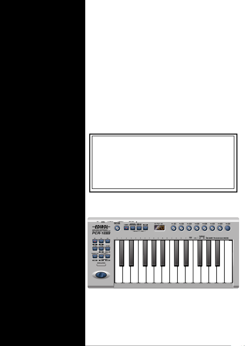
USB Audio Interface / MIDI Keyboard Controller PCR-1
fig.pcr-1
●
USB cable
Use this to connect the USB connector of your computer with the USB connector of the
PCR-1. For details on connections and driver installation, refer to
: p. 31 ).
* Please use only the included USB cable. If you require a replacement due to loss or damage, please contact a
“EDIROL/Roland Service Center” listed in the “Information” section at the end of this manual.
Setup (Windows
: p. 14 /
Macintosh
●
CD-ROM
This contains drivers and editors for use with the PCR-1.
●
Template sheets (two sheets)
One of these templates lists the messages that are assigned to the knobs and sliders (controllers) by
GM2 memory (memory no. 0). A blank sheet is also included for you to make a note of your own
controller settings.
●
Owner’s Manual
This is the manual you are reading. Please keep it on hand for reference.
6
Page 7

Quick page reference table
Before you begin
Using the audio functionality
Using the MIDI functionality
Making system settings
Trouble Shooting
Driver Installation
Settings p. 44
Names of things and what they do p. 9
Table of operating modes p. 50
System settings p. 93
Audio and MIDI flow p. 43
Playing sounds on your computer p. 46
Recording sound on your computer p. 47
Digital recording the output of the PCR-1 on a CD/MD/DAT p. 49
Startup mode p. 51
Features Useful When Playing p. 52
Pitch Bend p. 52
Modulation p. 52
Octave Shift p. 52
Transpose p. 52
Changing memory sets p. 59
Transmitting the current controller values all at once p. 60
Assign MIDI messages p. 61
Note Assign p. 63
Aftertouch Assign p. 65
Control Change Assign p. 68
Program Change Assign p. 71
RPN/NRPN Assign p. 74
Sys Ex. Assign p. 77
Tempo Assign p. 85
Copying a MIDI message assignment p. 86
Canceling a MIDI message assignment p. 87
Saving a memory set p. 88
Transmitting/receiving bulk data p. 89
Protecting a memory set p. 92
F8 Clock p. 94
Velocity Offset p. 94
Keyboard Port Set p. 94
H-Activity On / Off p. 95
USB MIDI Driver Mode p. 95
Startup Memory p. 95
Factory Reset p. 95
Pitch Bend Time p. 97
USB Audio Sampling Frequency p. 96
USB Audio Driver Mode p. 96
Direct Monitor On / Off p. 97
Pitch Bend Time p. 97
Modulation Setting p. 97
Problems related to the USB driver p. 106
Problems when using the PCR-1 p. 111
p. 14, p. 31
7
Page 8

Contents
USING THE UNIT SAFELY............... 3
IMPORTANT NOTES ........................ 4
Contents of the package ................. 6
Quick page reference table............. 7
Names of things and what they do 9
Panel................................................................ 9
Rear Panel..................................................... 12
Setup ......................13
Getting Connected and Installing
Drivers (Windows) ......................... 14
Installing the driver..................................... 14
Settings and checking ................................. 26
Getting Connected and Installing
Drivers (Macintosh) ....................... 31
Mac OS X users ............................................ 31
Installing the driver............................... 31
Setting the audio device........................ 32
Mac OS 9 users............................................. 33
Installing the PCR-1 driver................... 33
Setting the driver ................................... 34
Installing the ASIO driver .................... 38
Selecting Sounds on a Sound Module
(Sending Program Change / Bank Select
Massages)......................................................55
Transmitting a Reset message.................... 58
Changing the Memory Sets........................ 59
Transmitting the current controller values
all at once (SNAPSHOT)............................. 60
Assign MIDI messages (EDIT)................... 61
NOTE ASSIGN .......................................63
AFTERTOUCH ASSIGN....................... 65
CONTROL CHANGE ASSIGN ...........68
PROGRAM CHANGE ASSIGN...........71
RPN / NRPN ASSIGN.......................... 74
Sys Ex. ASSIGN...................................... 77
TEMPO ASSIGN .................................... 85
Copying a MIDI message assignment
(ASSIGN COPY) ..........................................86
Canceling a MIDI message assignment
(NO ASSIGN).............................................. 87
Saving a memory set (SAVE)..................... 88
Transmitting/receiving bulk data
(BULK).......................................................... 89
Protecting a memory set (PROTECT)....... 92
System settings ............................. 93
Appendices ............. 99
Operation ...............41
Basic use ........................................ 42
Basic connections......................................... 42
Audio and MIDI flow ................................. 43
Input / output devices ............................... 44
Use audio functionality ................. 46
Playing sounds on your computer............ 46
Recording sound on your computer ........ 47
Digitally recording sound from your
computer....................................................... 49
Use MIDI functionality ................... 50
Table of operating modes........................... 50
Startup mode................................................ 51
Features Useful When Playing .................. 52
Setting the MIDI Transmit Channel ......... 53
8
Memory sets................................. 100
Troubleshooting .......................... 106
Problems related to the USB driver.........106
Problems when using the PCR-1............. 111
MIDI implementation.................... 117
Main specifications...................... 122
index ............................................. 123
Page 9
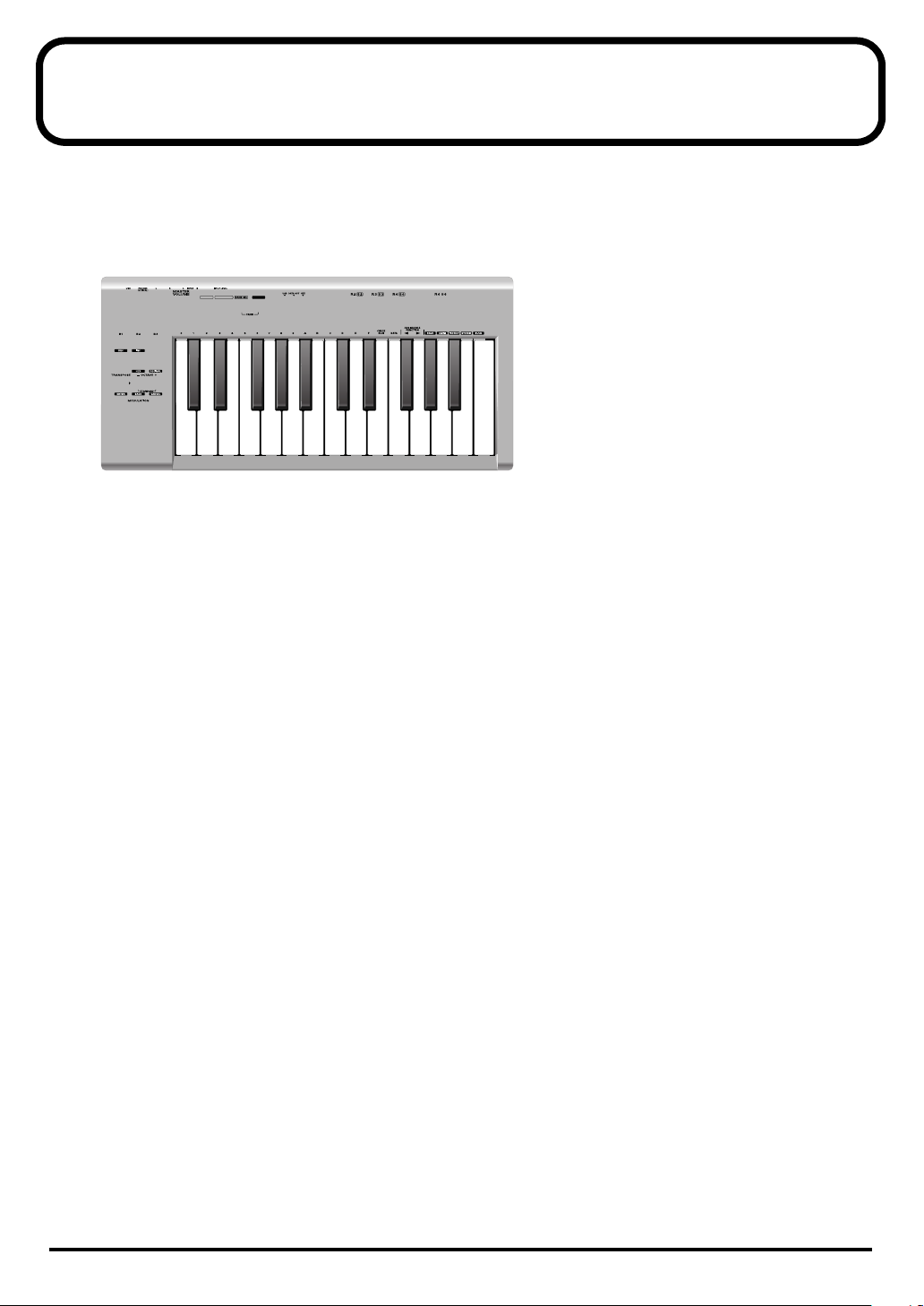
Names of things and what they do
Panel
fig.panel-1
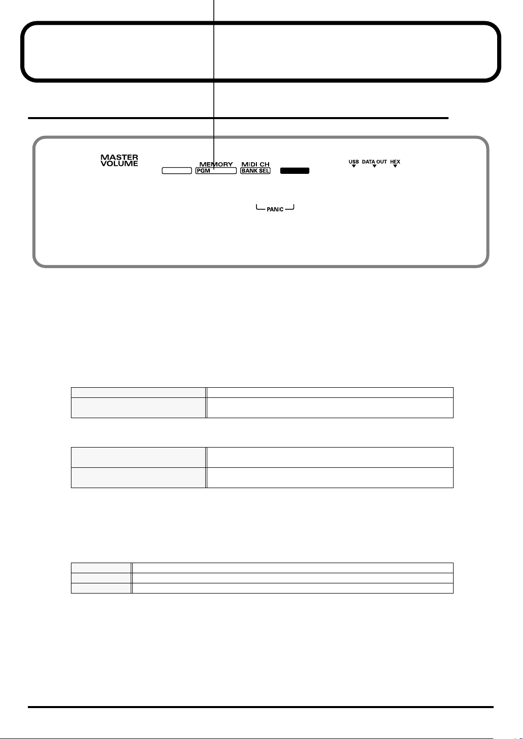
1 Master volume knob
This adjusts the volume that is output from the headphone jack, the master output jacks.
* This does not effect the volume that is output from the digital output jacks.
2 SHIFT Button
Use this in conjunction with other buttons.
3 MEMORY / PGM CHANGE Button
Press the[MEMORY] Button
Press the
then press the
[SHIFT]
[MEMORY]
so it is lit, and
.
Accesses memories that are stored within the PCR-1.
Transmits program change messages on the current channel.
4 MIDI CH / BANK SEL Button
Press the [MIDI CH] Button
Press the
then press the
[SHIFT]
[MIDI CH]
so it is lit, and
.
Specifies the transmission channel (
keyboard and bender.
Transmits bank select messages on the current channel.
5 EDIT Button
Used to assign MIDI messages to the controllers.
6 Display
Indicates the current status and various other information.
USB
DATA OUT
HEX
Lights if the PCR-1 is connected to your computer via USB.
This will blink when MIDI messages are transmitted via USB or MIDI OUT.
Lights when the value shown in the display is hexadecimal.
“current channel”
) for the
9
Page 10
Names of things and what they do
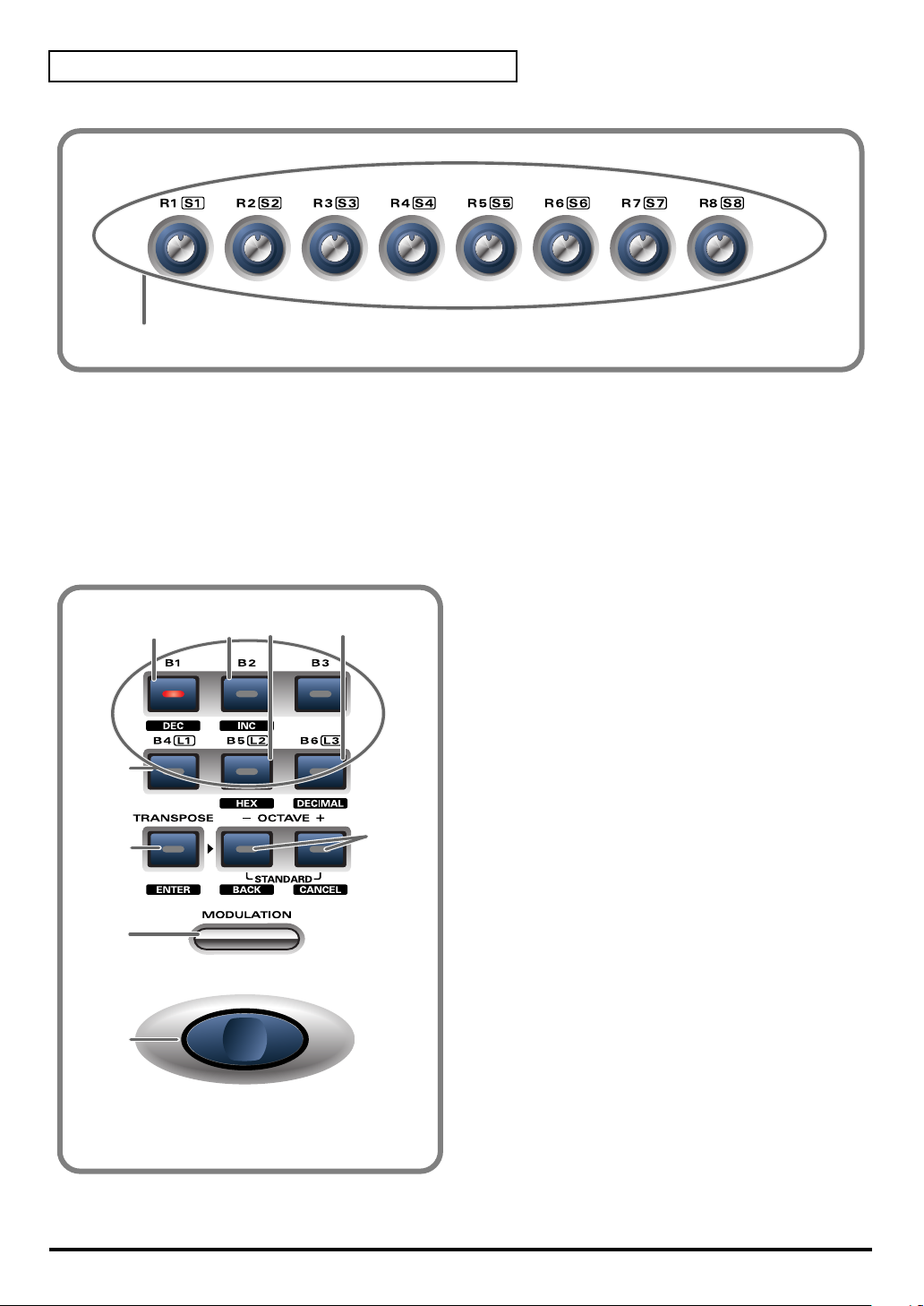
fig.panel-2
7
7 Controllers [R1] – [R8] , [S1] ( [SHIFT] + [R1] ) – [S8] ( [SHIFT] + [R8] )
You can assign MIDI messages to these controllers.
(➝Assign MIDI messages (EDIT)
When the
the button is lit (SHIFT ON), they correspond to [S1]--[S8].
[SHIFT]
button is unlit (SHIFT OFF), these controllers correspond to [R1]--[R8]. When
(p. 61))
fig.panel-3
12
13
15
16
8 DEC Button
9
8
10 11
Decreases the value of a setting by one (except
in
PLAY mode
(p. 51)).
9 INC Button
Increases the value of a setting by one (except
in
PLAY mode
(p. 51)).
10 HEX Button
14
When not in
mode to Hexadecimal (Hexadecimal input
mode).
PLAY mode
(p. 51), sets the input
11 DECIMAL Button
When not in
mode to Decimal (Decimal input mode).
PLAY mode
(p. 51), sets the input
12 Controllers [B1] – [B6], [L1] – [L3]
You can assign MIDI messages to these
controllers.(➝Assign MIDI messages (EDIT)
(p. 61))
10
Page 11

Names of things and what they do
13 TRANSPOSE / ENTER Button
Use
[TRANSPOSE]
Also, in any mode except PLAY mode, it functions as the
press to confirm the settings you’ve made.
+
[OCTAVE -/+]
to transpose the pitch of the keyboard in semitone steps.
[ENTER]
button, which you need to
14 OCTAVE - / +
Press
[OCTAVE - / +]
When not in PLAY mode, use these buttons to return to the previous setting item (the
button) or to cancel the setting and return to PLAY mode (the
to shift the pitch of the keyboard up or down in steps of an octave.
[CANCEL]
button).
15 MODULATION Button
This button can be used to apply vibrato.
16 BENDER Switch
This switch can be used to modify the pitch.
[BACK]
11
Page 12
Names of things and what they do
Rear Panel
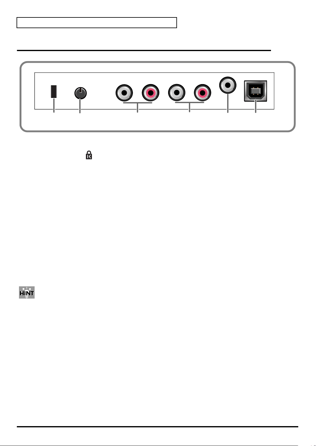
fig.rear
17
18
19 20
21
17 Security Slot ( )
http://www.kensington.com/
18 Input volume
This dual concentric knob adjusts the input level to
input jacks L and R
.
19 Input jacks (PCA Pin Type)
These are input jacks for analog audio signals. You can connect dynamic mics, guitars, or audio
devices. You must set the
have connected.
If you connect a guitar or mic only to the L jack or R jack, the signal will be monaural.
Input select switch
to the position appropriate for the device you
20 Master output jacks (PCA Pin Type)
These are analog audio output jacks. You can connect them to your external monitor speaker
system.
21 Digital output jack / Headphone jack
* The same jack serves as both the headphone jack and digital output jack.
fig.hint
Optical
These are digital jacks for connecting optical cables. Digital jacks for connecting coaxial cables
are labeled Coaxial.
22
• Use these jacks to output digital audio to a digital audio device such as a MD/DAT.
On the PCR-1, the input from the input jacks cannot be output directly to the Digital output
connector.
• You can connect a set of headphones to this jack. The headphone jack will output the same
signal as the master output jacks and digital output jacks. Sound will be output from the
master output jacks even if headphones are connected.
22 USB connector
Use this when connecting the PCR-1 to your computer via a USB cable.
12
Page 13

Setup
This section explains how to install the drivers needed for connecting the PCR-1 to a computer,
and make the necessary settings.
Getting Connected and Installing Drivers (Windows)........... (p. 14)
Getting Connected and Installing Drivers (Macintosh).......... (p. 31)
What is a driver?
A “driver” is software that transfers data between the PCR-1 and application software running
on your computer, when your computer and the PCR-1 are connected by a USB cable. The
driver sends data from your application to the PCR-1, and from the PCR-1 to your application.
13
Page 14
Getting Connected and Installing Drivers (Windows)
Installing the driver
The installation procedure will differ depending on your system.
Please proceed to one of the following sections, depending on the system you
use.
• Windows XP users ........................................................... (p. 14)
• Windows 2000 users......................................................... (p. 20)
• Windows Me/98 users .................................................... (p. 25)
Windows XP users
If you are using Windows
1
Disconnect all USB cables except for a USB keyboard and USB mouse (if
used).
2
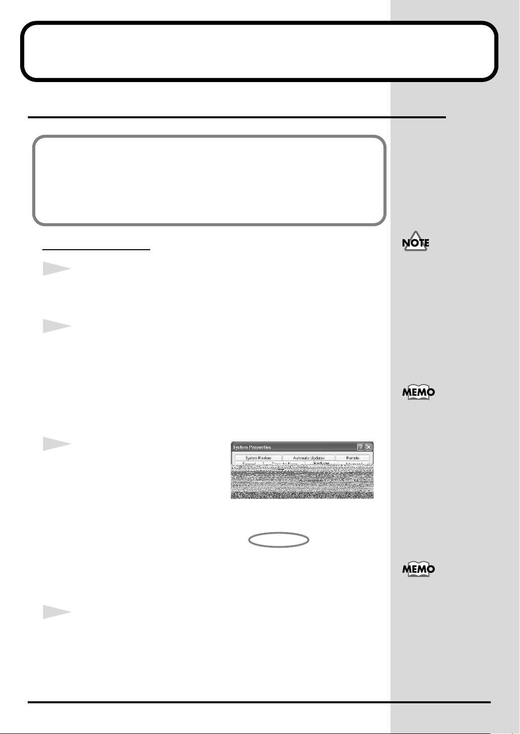
Open the
1.
System Properties
Click the Windows
Panel.
dialog box.
start
menu, and from the menu, select Control
XP Professional, you must
log on using a user name
with an administrative
account type (e.g.,
Administrator). For details
on user accounts, please
consult the system
administrator of your
computer.
2.
In
“Pick a category”
3.
In
“or pick a Control Panel icon”
fig.2-1
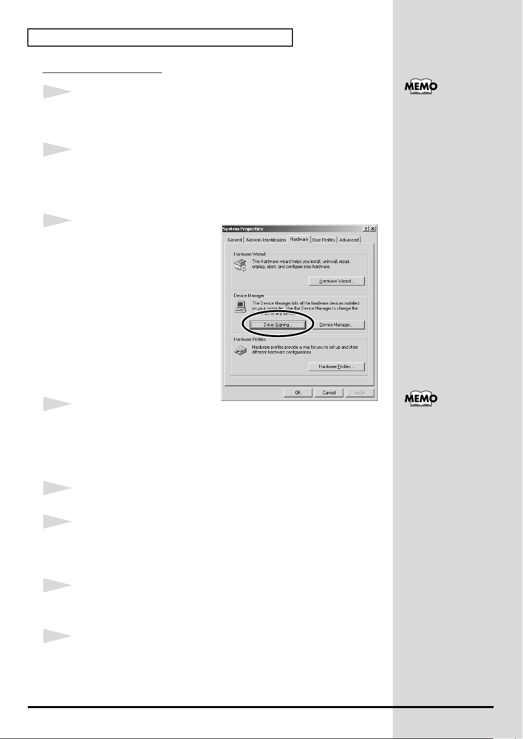
3
Click the
click
Open the
dialog box.
4
Make sure that
“Ignore”
If it is set to
If it is not set to
“Block”). Then change the setting to
Hardware
[Driver Signing]
Driver Signing Options
.
“Ignore”
tab, and then
“What action do you want Windows to take?”
“Ignore”
, click
“Performance and Maintenance”
, click the
.
, simply click
, make a note of the current setting (“Warn” or
[OK]
.
“Ignore”
System
and click
icon.
[OK].
.
is set to
Depending on how your
system is set up, the
System icon may be
displayed directly in the
Control Panel (the Classic
view). In this case, double-
click the System icon.
If you changed “What
action do you want
Windows to take?”, you
must restore the previous
setting after you have
installed the driver. (If you
changed “What action do
you want Windows to
take?” (p. 18))
14
Page 15
5
Click
[OK]
to close the
System Properties
Getting Connected and Installing Drivers (Windows)
dialog box.
6
Exit all currently running software (applications).
Also close any open windows. If you are using virus checking or similar
software, be sure to exit it as well.
7
Prepare the CD-ROM.
Insert the CD-ROM into the CD-ROM drive of your computer.
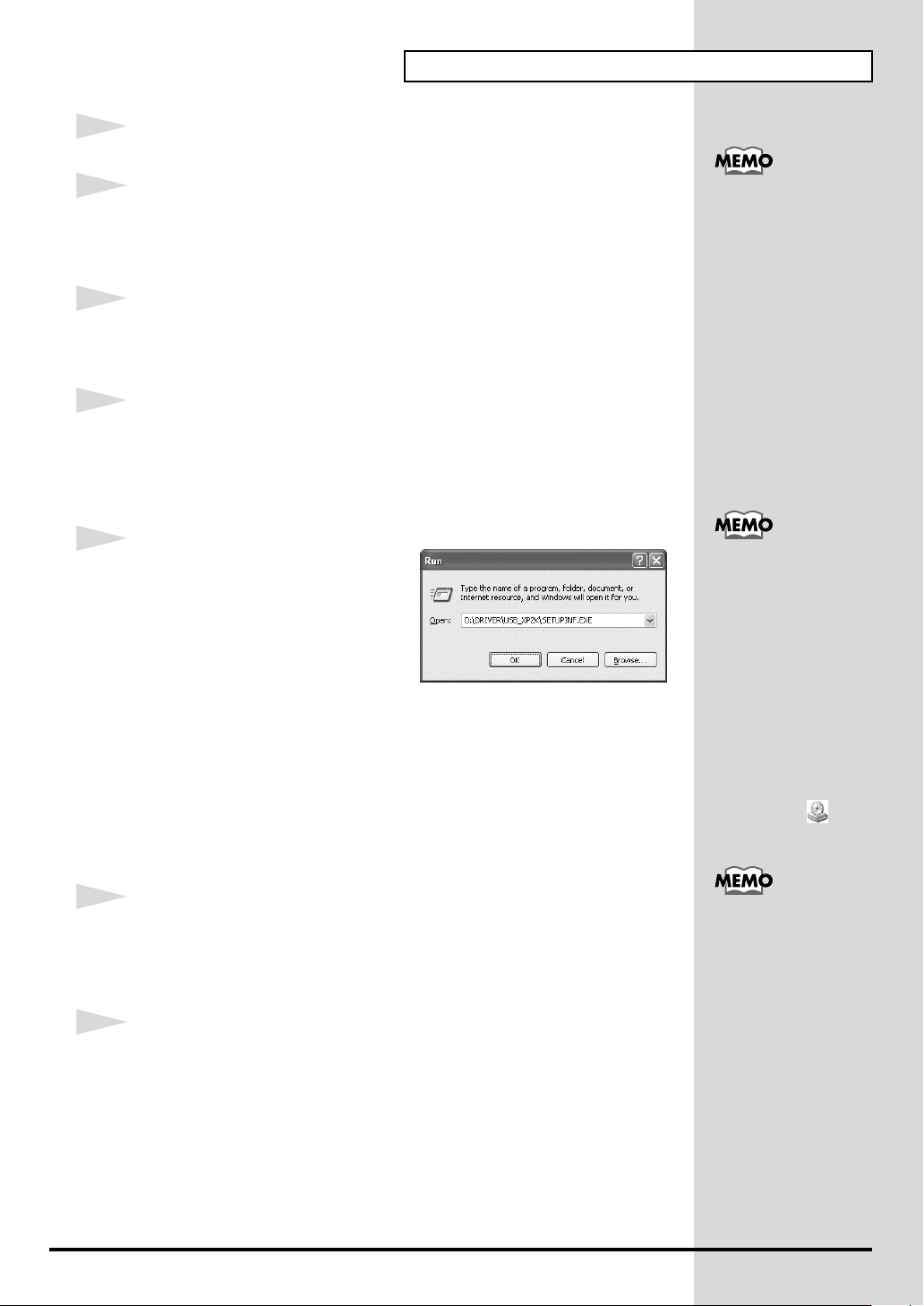
8
Click the Windows
“Run...”
The
“Run...”
fig.2-3_30
9
Specify the name of the file you want
to execute.
Enter the following into the
field, and click
(drive name) : \Driver\USB_XP2K\SETUPINF.EXE
The
SetupInf
You are now ready to install the driver.
* In the explanatory example shown here, the drive name is given as
name
“D:”
may be different for your system. Specify the drive name of your CD-
ROM drive.
start
button. From the menu that appears, select
dialog box will appear.
“Open”
[OK]
.
dialog box will appear.
“D:”
. The drive
If the screen indicates
“Windows can perform
the same action each
time you insert a disk or
connect a device with
this kind of file”, click
[Cancel].
To check the drive name
Click the Start button, and
choose My Computer from
the menu that appears. In
the window that appears,
check the drive name of
the CD-ROM drive into
which you inserted the
CD-ROM in step 7.
The drive name is the (D:)
or (E:) displayed by the
CD-ROM drive .
10
Use the
Near the task bar, your computer will indicate
Please wait.
11
The
Select
[Next]
USB cable
Found New Hardware Wizard
“Install from a list or specific location (Advanced)”
.
to connect the
PCR-1
to your
will appear.
computer
“Found New Hardware”
.
, and click
This unit is equipped with
.
a protection circuit. A brief
interval (a few seconds)
after connecting the USB
cable is required before the
unit will operate normally.
15
Page 16
Getting Connected and Installing Drivers (Windows)
fig.2-7_20
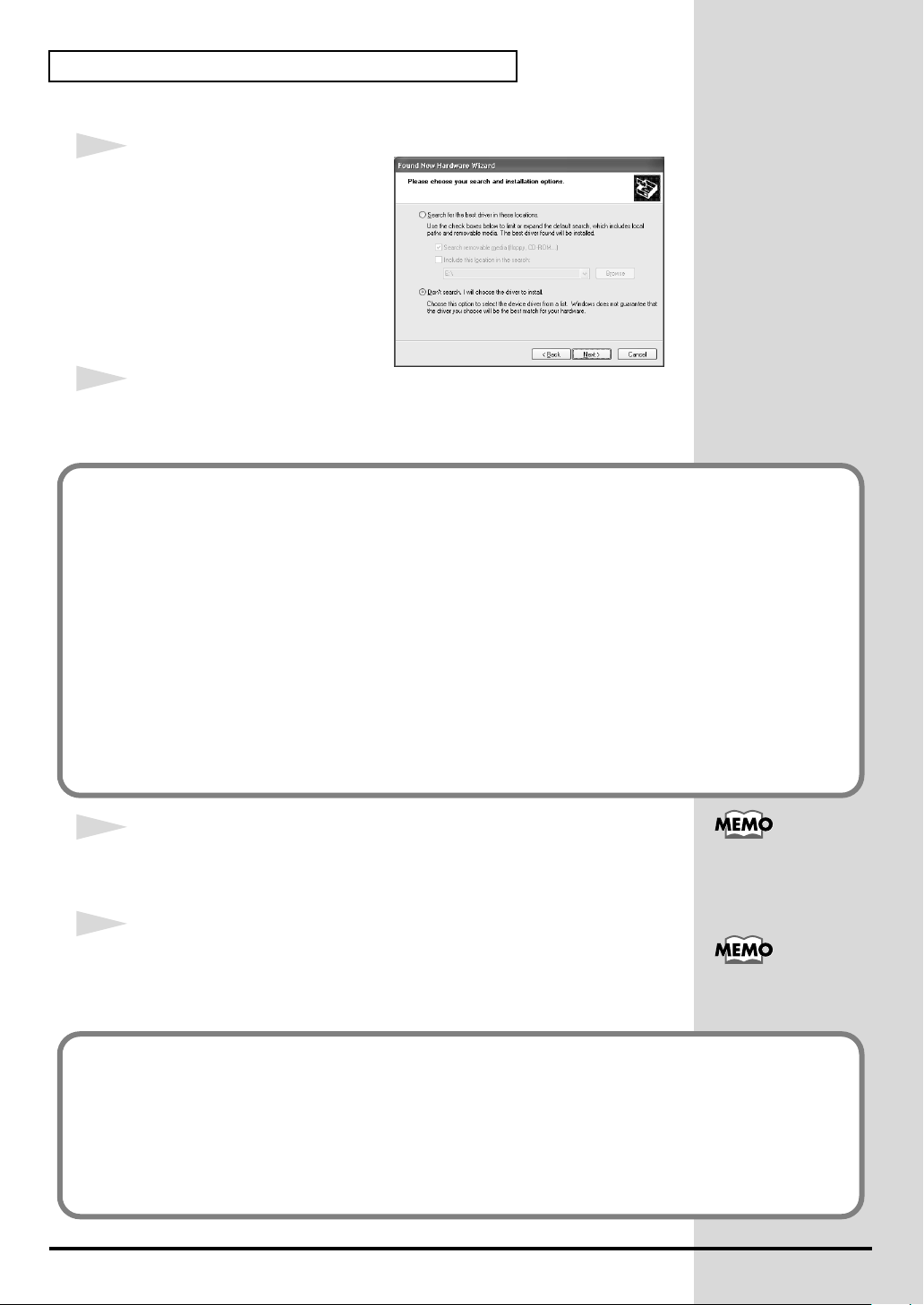
12
The screen will indicate
choose your search and
installation options”
Select
“Don’t search. I will choose
the driver to install”
[Next]
.
13
Make sure that the
“EDIROL PCR-1 MIDI”
If the “What action do you want Windows to take?” (Step 4) setting was not set to “Ignore”, a
“Hardware Installation” dialog box will appear.
“Please
.
, and click
“Model”
, and click
field indicates
[Next]
. Driver installation will begin.
“EDIROL PCR-1 WAVE”
or
If “What action do you want Windows to take?” is set to “Warn”
A dialog box with a “!” symbol will appear.
1. Click [Continue Anyway].
2. Continue the installation.
If “What action do you want Windows to take?” is set to “Block”
A dialog box with a “x” symbol will appear.
1. Click [OK].
2. When the “Found New Hardware Wizard” appears, click [Finish].
3. Return to step 1 (p. 14) and re-install the driver from the beginning of the procedure.
14
The
Insert Disk
Click
[OK]
15
The
Files Needed
Input the following into the
(drive name):\DRIVER\USB_XP2K
If the “What action do you want Windows to take?” (Step 4) setting was not set to “Ignore”, a
“Hardware Installation” dialog box will appear.
dialog box will appear.
.
dialog box will appear.
“Copy files from”
field, and click
[OK]
The Insert Disk dialog
may not appear. In that
case, proceed to the next
step.
.
Specify the drive name of
your CD-ROM drive..
If “What action do you want Windows to take?” is set to “Warn”
A dialog box with a “!” symbol will appear.
1. Click [Continue Anyway].
2. Continue the installation.
16
Page 17
16
The screen will indicate
Click
[Finish]
17
The
Found New Hardware Wizard
select
“Install from a list or specific location (Advanced)”
[Next]
.
fig.2-7_20
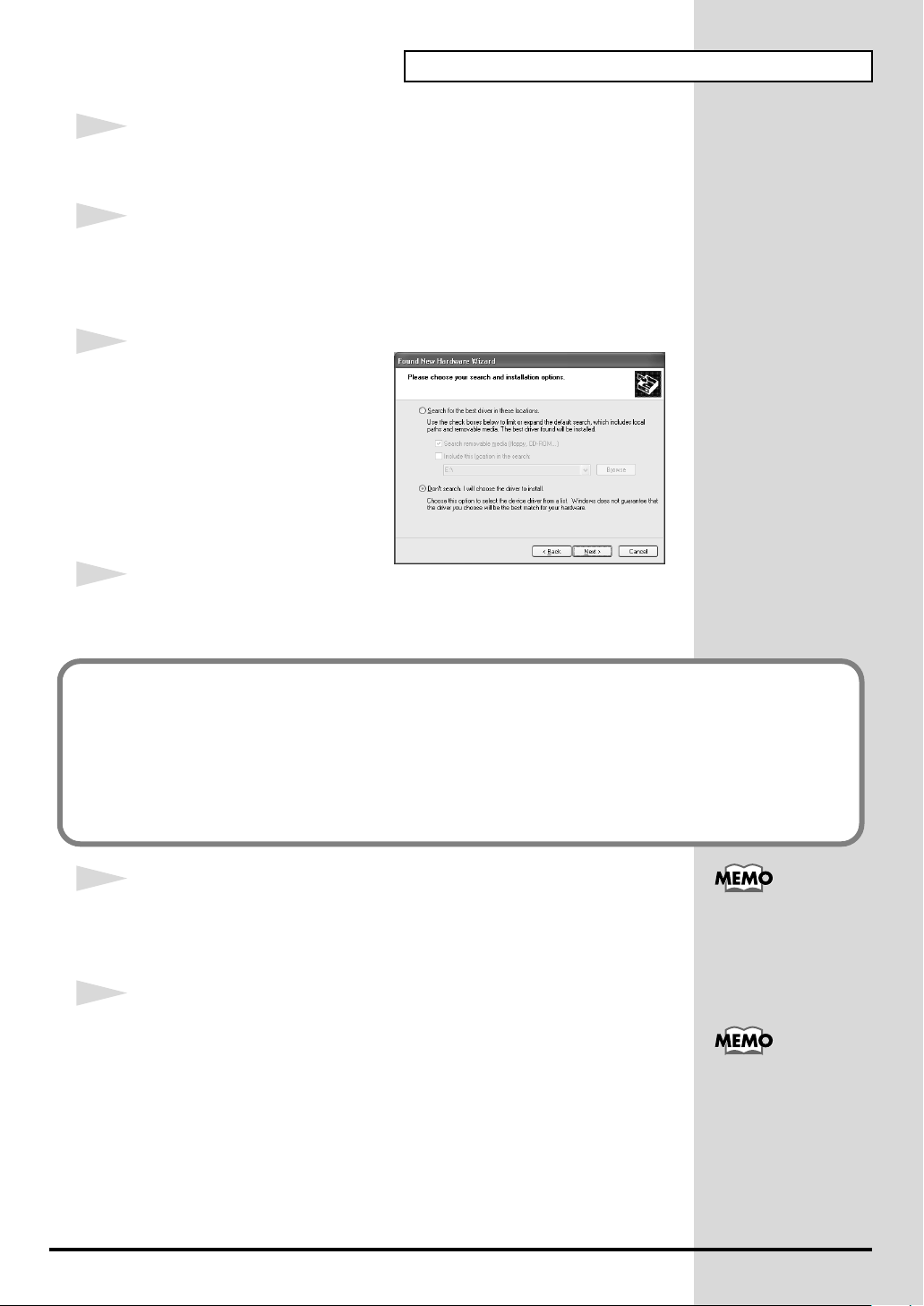
18
The screen will indicate
choose your search and
installation options”
Select
“Don’t search. I will choose
the driver to install”
[Next]
.
19
Make sure that the
“EDIROL PCR-1 MIDI”
.
Getting Connected and Installing Drivers (Windows)
“Completing the Found New Hardware Wizard”
will appear again.
, and click
“Please
.
, and click
“Model”
field indicates
, and click
“EDIROL PCR-1 WAVE”
[Next]
. Driver installation will begin.
.
or
If the “What action do you want Windows to take?” (Step 4) setting was not set to “Ignore”, a
“Hardware Installation” dialog box will appear.
If “What action do you want Windows to take?” is set to “Warn”
A dialog box with a “!” symbol will appear.
1. Click [Continue Anyway].
2. Continue the installation.
20
The
Insert Disk
Click
[OK]
21
The
Files Needed
Input the following into the
(drive name):\DRIVER\USB_XP2K
dialog box will appear.
.
dialog box will appear.
“Copy files from”
field, and click
[OK]
The Insert Disk dialog
may not appear. In that
case, proceed to the next
step.
.
Specify the drive name of
your CD-ROM drive.
17
Page 18
Getting Connected and Installing Drivers (Windows)
If the “What action do you want Windows to take?” (Step 4) setting was not set to “Ignore”, a
“Hardware Installation” dialog box will appear.
If “What action do you want Windows to take?” is set to “Warn”
A dialog box with a “!” symbol will appear.
1. Click [Continue Anyway].
2. Continue the installation.
22
The screen will indicate
Click
[Finish]
Wait until
23
When driver installation has been completed, the
dialog box will appear.
Click
[Yes]
.
“Found New Hardware”
. Windows will restart automatically.
“Completing the Found New Hardware Wizard”
appears near the taskbar.
System Settings Change
.
If the System Settings
Change
not appear, restart
Windows from the Start
menu.
If you changed “What action do you want Windows to
take?”
If you changed the What action do you want Windows to take? (p. 14)
setting, restore the original setting after Windows restarts.
1. Log on to Windows using the user name of an administrative account
(e.g., Administrator).
2. Click the Windows start button, and from the menu that appears, select
Control Panel.
3. In “Pick a category,” click “Performance and Maintenance”.
4. In “or pick a Control Panel icon”, click the System icon. The System
Properties dialog box will appear.
5. Click the Hardware tab, and then click [Driver Signing]. The Driver
Signing Options dialog box will appear.
6. Return the What action do you want Windows to take? setting to the
original setting (either “Warn” or “Block”), and click [OK].
7. Click [OK]. The System properties dialog box will close.
Depending on how your
system is set up, the
System icon may be
displayed directly in the
Control Panel (classic
view). In this case, double-
click the System icon.
dialog box does
18
This completes installation of the driver.
Next, we recommend that you enable background processing on your computer, so MIDI and
audio processing will be as smooth as possible.(➔ Enabling background processing (p. 19))
Page 19
■
Enabling background processing
In Windows XP, make settings to enable background processing. If you fail
to make this setting, you may experience interruptions in the sound. To
ensure that MIDI and audio processing occurs smoothly, use the following
procedure to make settings.
1
Open the
1.
2.
System Properties
Click the Windows start menu, and from the menu, select Control
Panel.
In
“Pick a category”
dialog box.
, click
“Performance and Maintenance”
Getting Connected and Installing Drivers (Windows)
.
3.In “or pick a Control Panel icon”
2
Click the
3
At the right of the
The
4
Click the
fig.2-30a
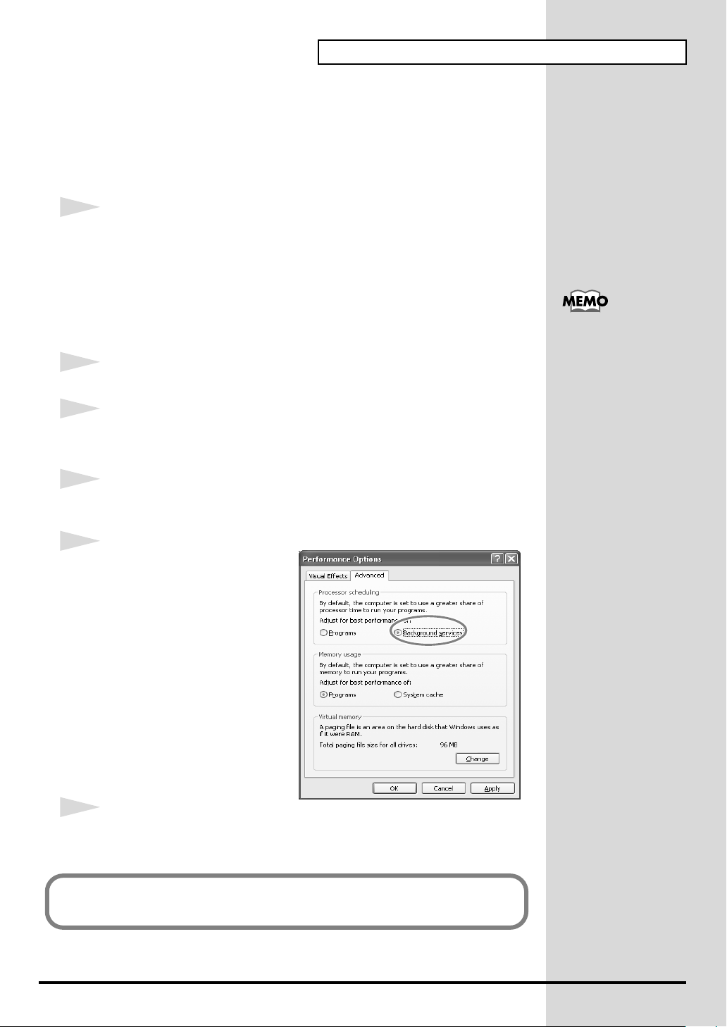
5
In the
field, select
services”
Advanced
Performance Options
Advanced
Processor Scheduling
“Background
, and click
tab.
Performance
tab.
[OK]
, click the
field, click
dialog box will appear.
.
[Settings]
System
.
icon.
Depending on how your
system is set up, the
System icon may be
displayed directly in the
Control Panel (the Classic
view). In this case, double-
click the System icon.
6
In the
System Properties
The
System Properties
Next, make MIDI device and audio device settings.
(➝Specifying the audio and MIDI input/output destination (p. 26))
dialog box, click
dialog box will close.
[OK]
.
19
Page 20
Getting Connected and Installing Drivers (Windows)
Windows 2000 users
1
Disconnect all USB cables except for a USB keyboard and USB mouse (if
used).
2
Open the
Click the Windows
Settings | Control Panel
fig.05-2_30
3
Click the
click
The
dialog box will appear.
System Properties
Start
button, and from the menu that appears, select
. In
Hardware
[Driver Signing]
Driver Signing Options
tab, and then
.
dialog box.
Control Panel
, double-click the
System
Log on to Windows as a
user with administrative
privileges (such as
Administrator)
icon.
4
Make sure that
If it is set to
If it is not set to “Ignore”, make a note of the current setting (“Warn” or
“Block”). Then change the setting to
5
Click
[OK]
6
Exit all currently running software (applications).
Also close any open windows. If you are using virus checking or similar
software, be sure to exit it as well.
7
Prepare the CD-ROM.
Insert the CD-ROM into the CD-ROM drive of your computer.
8
Click the Windows
“Run...”
The
“Run...”
“File signature verification”
“Ignore”
to close the
dialog box will appear.
, simply click
System Properties
Start
button. From the menu that appears, select
[OK]
.
“Ignore”
is set to
and click
dialog box.
“Ignore”
[OK]
.
.
If you changed “File
signature verification”,
you must restore the
previous setting after you
have installed the driver.
(➝If you changed “File
signature verification” (p.
23))
20
Page 21
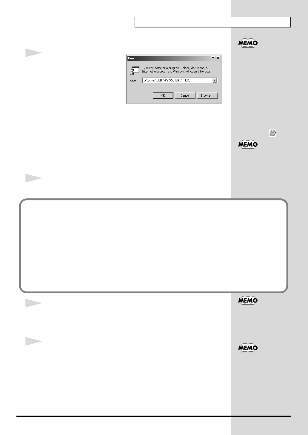
fig.05-5_30
b
Getting Connected and Installing Drivers (Windows)
9
In the dialog box that appears,
input the following into the
“Open”
(drive name) : \Driver\USB_XP2K\SETUPINF.EXE
The
You are now ready to install the driver.
* In the explanatory example shown here, the drive name is given as “D:”. The drive
name
ROM drive.
10
Use the
If the “File signature verification” (Step 4) setting was not set to “Ignore”, a “Digital Signature Not
Found” dialog box will appear.
field, and click
SetupInf
“D:”
dialog box will appear.
may be different for your system. Specify the drive name of your CD-
USB cable
[OK]
.
to connect the
PCR-1
to your
computer
.
To check the drive name
In the Windows desktop,
double-click the My
Computer icon. In the
window that appears,
check the drive name of
the CD-ROM drive into
which you inserted the
CD-ROM in step7.
The drive name is the (D:)
or (E:) displayed by the
CD-ROM drive .
This unit is equipped with
a protection circuit. A brief
interval (a few seconds)
after connecting the USB
cable is required before the
unit will operate normally.
If “File signature verification” is set to “Warn”
1. Click [Yes].
2. Continue the installation.
If “File signature verification” is set to “Block”
1. Click [OK].
2. When the “Found New Hardware Wizard” appears, click [Finish].
3. Return to step 1 (p. 20) and re-install the driver from the beginning of the procedure.
11
The
Insert Disk
Click
[OK]
12
The
Files Needed
Input the following into the
(drive name) : \DRIVER\USB_XP2K
dialog box will appear.
.
dialog box will appear.
“Copy files from”
field, and click
[OK]
If the Insert Disk dialog
ox does not appear,
proceed to the next step.
.
Specify the drive name of
your CD-ROM drive.
21
Page 22
Getting Connected and Installing Drivers (Windows)
b
b
If the “File signature verification” (Step 4) setting was not set to “Ignore,” a “Digital Signature Not
Found” dialog box will appear.
If “File signature verification” is set to “Warn”
1. Click [Yes].
2. Continue the installation.
13
The screen will indicate
Click
[Finish]
14
The
System Settings Change
Click
[Yes]
Log on to Windows as a user with administrative privileges (e.g.,
Administrator).
.
. Windows will restart automatically.
“Completing the Found New Hardware Wizard”
dialog box will appear.
.
15
After you have logged on to Windows, the
appear again.Click
16
The
Files Needed
Input the following into the
(drive name) : \DRIVER\USB_XP2K
If the “File signature verification” (Step 4) setting was not set to “Ignore,” a “Digital Signature Not
Found” dialog box will appear.
[OK]
.
dialog box will appear.
“Copy files from”
Insert Disk
field, and click
dialog box will
[OK]
.
If the Insert Disk dialog
ox does not appear,
proceed to the next step.
Specify the drive name of
your CD-ROM drive.
If “File signature verification” is set to “Warn”
1. Click [Yes].
2. Continue the installation.
17
The screen will indicate
Click
[Finish]
“Completing the Found New Hardware Wizard”
.
If the Found New
.
Hardware Wizard dialog
ox does not appear,
proceed to the next step.
22
Page 23

Getting Connected and Installing Drivers (Windows)
18
The
System Settings Change
Click
[Yes]
. Windows will restart automatically.
If the
System Settings Change
Windows from the Start menu.
dialog box may appear.
dialog box does not appear, restart
If you changed “File signature verification”
If you changed the “File signature verification” (p. 20) setting, restore
the original setting after Windows restarts.
1. After Windows restarts, log in to Windows as a user with
administrative privileges, (such as Administrator).
2. In the Windows desktop, right-click the My Computer icon, and
from the menu that appears, select Properties. The System
Properties dialog box will appear.
3. Click the Hardware tab, and then click [Driver Signing]. The Driver
Signing Options dialog box will appear.
4. Return the “File signature verification” setting to the original
setting (either “Warn” or “Block”), and click [OK].
5. Click [OK]. The System Properties dialog box will close.
If the System Settings
Change
not appear, restart
Windows from the Start
menu.
dialog box does
This completes installation of the driver.
Next, we recommend that you enable background processing on your
computer, so MIDI and audio processing will be as smooth as possible.
(➔ Enabling background processing (p. 24))
23
Page 24
Getting Connected and Installing Drivers (Windows)
■
Enabling background processing
In Windows 2000, make settings to enable background processing. If you fail
to make this setting, you may experience interruptions in the sound. To
ensure that MIDI and audio processing occurs smoothly, use the following
procedure to make settings.
1
Click the Windows
Settings | Control Panel
2
Click the
3
At the right of the
The
Performance Options
fig.back2000
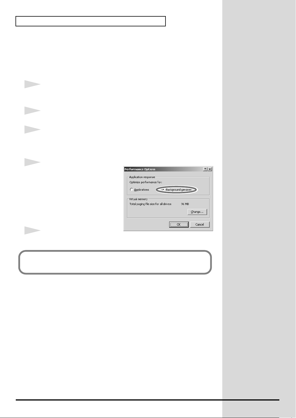
4
In the
Application response
choose
“Background services”
and click
Advanced
[OK]
Start
tab.
Performance
.
button, and from the menu that appears, select
. In
Control Panel
field, click
dialog box will appear.
field,
, double-click the
[Performance Options]
System
icon.
.
5
Click
[OK]
to close the
Next, make MIDI device and audio device settings.
(➝Specifying the audio and MIDI input/output destination (p. 26))
System Properties
dialog box.
24
Page 25

Getting Connected and Installing Drivers (Windows)
Windows Me/98 users
1
With the PCR-1 disconnected, start up Windows.
Disconnect all USB cables except for a USB keyboard and USB mouse (if
used).
If you are using virus checking or similar software, be sure to exit it as well.
2
Exit all currently running software (applications).
Also close any open windows. If you are using virus checking or similar
software, be sure to exit it as well.
3
Prepare the CD-ROM.
Insert the CD-ROM into the CD-ROM drive of your computer.
4
Click the Windows
The
“Run...”
fig.05-13_30
5
In the dialog box that appears,
input the following into the
“Open”
(drive name) : \Driver\USB_ME98\SETUPINF.EXE
field, and click
Start
button. From the menu that appears, select
dialog box will appear.
[OK]
.
Run...
.
To check the drive name
In the Windows desktop,
double-click the My
Computer icon. In the
window that appears,
check the drive name of
the CD-ROM drive into
which you inserted the
CD-ROM in step3.
The drive name is the (D:)
or (E:) displayed by the
CD-ROM drive .
The
SetupInf
You are now ready to install the driver.
* In the explanatory example shown here, the drive name is given as
name
“D:”
ROM drive.
6
Use the
The driver will be installed automatically.
7
In the SetupInf dialog box, click
Next, make MIDI device and audio device settings.
(➝Specifying the audio and MIDI input/output destination (p. 26))
dialog box will appear.
may be different for your system. Specify the drive name of your CD-
USB cable
to connect the
[OK]
PCR-1
.
to your
computer
“D:”
.
. The drive
This unit is equipped with
a protection circuit. A brief
interval (a few seconds)
after connecting the USB
cable is required before the
unit will operate normally.
If a message recommends
that you restart Windows,
restart Windows as
directed.
25
Page 26
Getting Connected and Installing Drivers (Windows)
Settings and checking
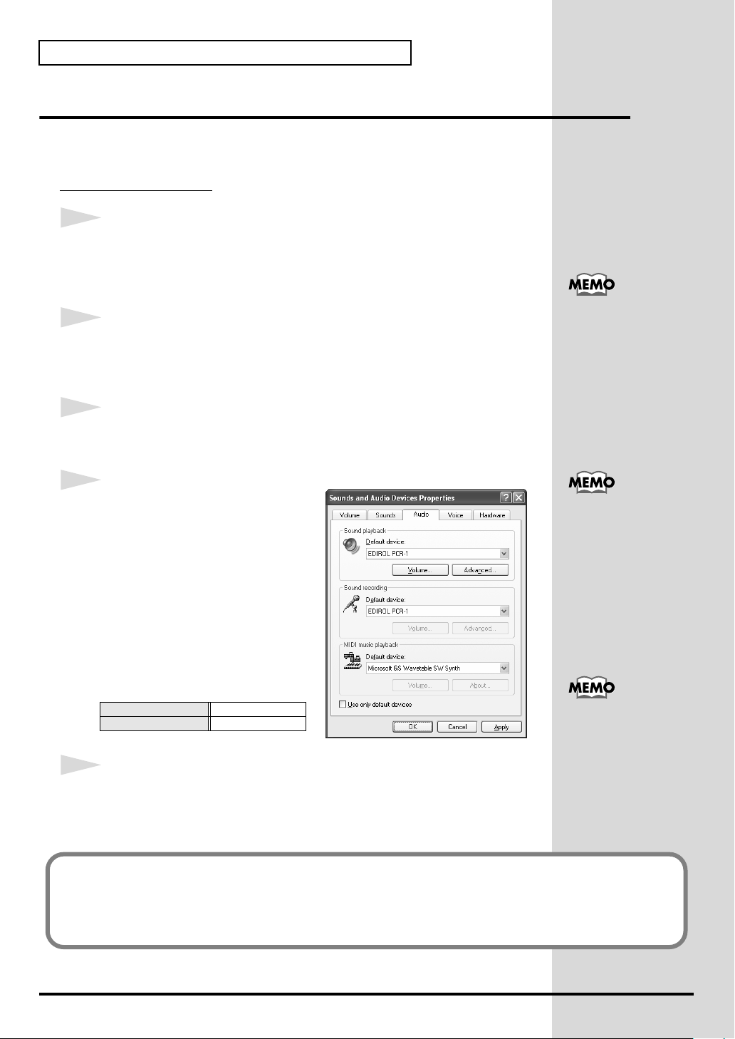
Specifying the audio and MIDI input/output destination
■
Windows XP users
1
Open
Control Panel
.
Click the Windows
Control Panel
2
Open the
In
“or pick a Control Panel icon”
3
Click the
fig.XP_J
4
For
located at the right of
, and select the following from the list
that appears.
Sounds and Audio Devices Properties
“Pick a category”
Audio
MIDI music playback
start
.
click
tab.
[Default device]
button, and from the menu that appears, select
dialog box.
“Sound, Speech, and Audio Devices”
, click the
, click the
sounds and Audio Devices
. Next, in
icon.
Depending on how your
system is set up, the
Sounds and Audio
Devices icon may be
displayed directly in the
Control Panel (the Classic
view). In this case, double-
click the Sounds and
Audio Devices icon.
For details on the PCR-1’s
input/output devices,
refer to Input / output
devices (p. 44)
26
Sound playback
Sound recording
5
Close the
Click
This completes settings for using the PCR-1 with an application that uses the standard
Windows device settings, such as Media Player.
For details on how to make these settings, refer to the owner’s manual for your software.
For details on the PCR-1’s input/output devices, refer to Input / output devices (p. 44).
Sounds and Audio Devices Properties
[OK]
to complete the settings.
EDIROL PCR-1
EDIROL PCR-1
dialog box.
For details on adjusting the
audio latency and using
ASIO Direct Monitor, refer
to Taking full advantage
(p. 29).
Page 27
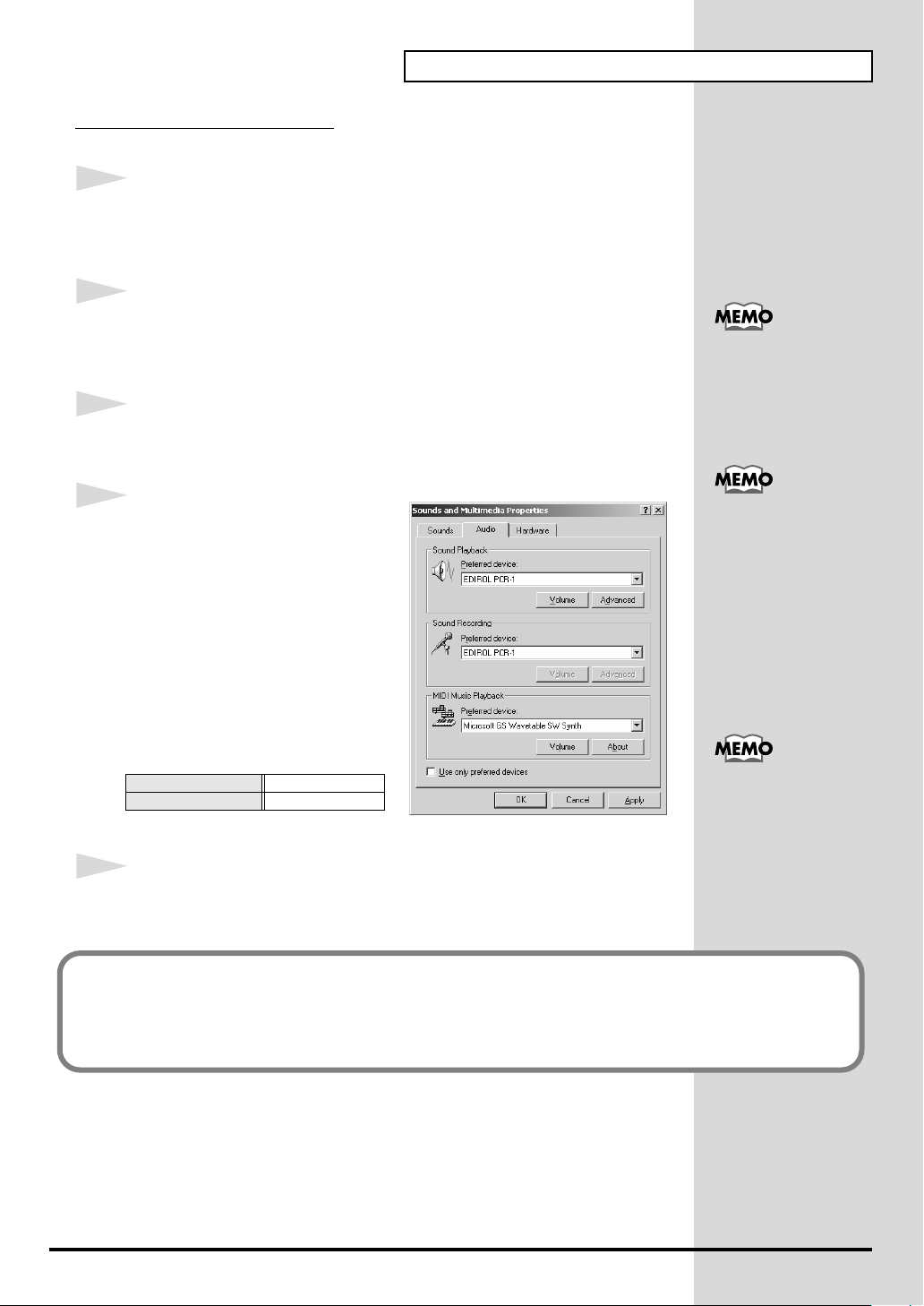
Windows 2000 / Me users
1
Open
Control Panel
.
Getting Connected and Installing Drivers (Windows)
Click the Windows
Settings | Control Panel
2
Open the
In
“Sounds and Multimedia Properties”
3
Click the
fig.MEe
4
For
located at the right of
device]
the list that appears.
Sounds and Multimedia Properties
Control Panel
Audio
MIDI music playback
, and select the following from
Start
, double-click the
tab.
[Preferred
button, and from the menu that appears, select
.
.
Sounds and Multimedia
dialog box.
, click the
icon to open the
If the Sound and
Multimedia icon is not
displayed, click “Show all
control panel options” in
the frame at the left.
For details on the PCR-1’s
input/output devices,
refer to Input / output
devices (p. 44).
Sound playback
Sound recording
5
Close the
Click
This completes settings for using the PCR-1 with an application that uses the standard
Windows device settings, such as Media Player.
For details on how to make these settings, refer to the owner’s manual for your software.
For details on the PCR-1’s input/output devices, refer to Input / output devices (p. 44).
Sounds and Audio Devices Properties
[OK]
to complete the settings.
EDIROL PCR-1
EDIROL PCR-1
dialog box.
For details on adjusting the
audio latency and using
ASIO Direct Monitor, refer
to Taking full advantage
(p. 29).
27
Page 28
Getting Connected and Installing Drivers (Windows)
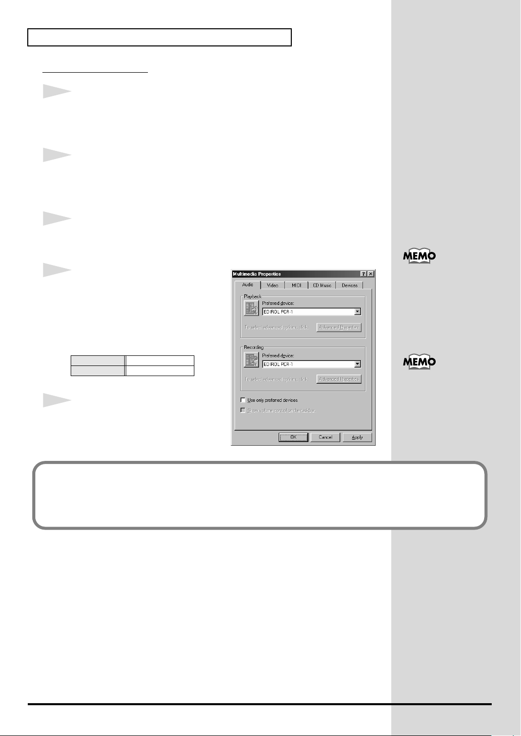
Windows 98 users
1
Open
Control Panel
.
Click the Windows
Settings | Control Panel
2
Open the
In
Properties”
3
Click the
fig.98_E
4
Specify the
Click the
Recording
selections from the list that appears,
and click
Playback
Recording
5
Close the
dialog box.
Click
Multimedia Properties
Control Panel
Audio
“Preferred device”
Playback
field, make the following
[Apply]
Multimedia Properties
[OK]
to complete the settings.
Start
, double-click the
dialog box.
tab.
field and
.
EDIROL PCR-1
EDIROL PCR-1
button, and from the menu that appears, select
.
dialog box.
Multimedia
.
icon to open the
“Multimedia
For details on the PCR-1’s
input/output devices,
refer to Input / output
devices (p. 44)
For details on adjusting the
audio latency and using
ASIO Direct Monitor, refer
to Taking full advantage
(p. 29).
28
This completes settings for using the PCR-1 with an application that uses the standard
Windows device settings, such as Media Player.
For details on how to make these settings, refer to the owner’s manual for your software.
For details on the PCR-1’s input/output devices, refer to Input / output devices (p. 44).
Page 29
■
b
Taking full advantage
Getting Connected and Installing Drivers (Windows)
Adjusting the audio latency
You can change the driver settings to adjust the
adjust the latency, change the
1
Open the
1.
2.
2
Adjust the driver buffer size.
The following setting will produce the shortest latency.
Set
3
Click
4
Restart the application that is using the PCR-1.
5
Play back audio data on your application.
“Driver Settings”
Open
“Control Panel”
Double-click
The
Driver Settings
“Audio Buffer Size”
[OK]
“EDIROL PCR-1”
to close the
Buffer Size
dialog box.
.
icon.
dialog box will appear.
to the far
driver settings
left (Min)
dialog box.
latency
in the
driver settings
.
of the audio. To
dialog box.
Latency is the time delay
from when an application
plays back audio data until
the sound is actually heard
from an audio device such
as the PCR-1.
In Windows XP, click
"Switch to Classic View"
to select Classic View on
your computer. If you're
not in Classic View, the
EDIROL PCR-1 icon won't
e shown.
In Windws Me, click
"Show all Control Panel
Options.”
If you are using an
application that has a
function for testing audio
devices, get it to perform
its tests.
If interruptions occur in the sound, repeat step 1 to step 5, and gradually increase
the buffer size specified in step 2 until interruptions no longer occur.
Depending on the
application you are using,
there may be a buffer size
or latency adjustment
function among the audio
settings of the application
as well. For details, refer to
the operation manual for
your application.
29
Page 30
Getting Connected and Installing Drivers (Windows)
b
Using ASIO Direct Monitor
If the PCR-1's
control the PCR-1's Direct Monitor settings from your ASIO 2.0 compatible
software.
DIRECT MONITOR ON / OFF
setting (p. 97) is
AUTO
, you can
1
Open the
1.
2.
2
Make the following settings.
Check the
3
Click
“Driver Settings”
Open the
Double-click
The
Driver Settings
“Use ASIO Direct Monitor”
[OK]
to close the
dialog box.
“Control Panel”
“EDIROL PCR-1”
dialog box will appear.
driver settings
In Windows XP, click
“Switch to classic view”
icon.
check box.
dialog box.
to switch the display to the
classic view. EDIROL
PCR-1 icon will not be
displayed unless the
classic view is selected.
In Windows Me, click
“View all Control Panel
options.”
When using ASIO Direct
Monitor, monitoring may
switch on/off at
unexpected times,
depending on the
application settings and on
the recording procedure. If
this occurs, uncheck the
check box in step 2 to
disable ASIO Direct
Monitor.
Depending on your
application, there may also
e an ASIO Direct
Monitor setting among the
audio settings of your
application. For details,
refer to the operation
manual for your
application.
30
Page 31

Getting Connected and Installing Drivers (Macintosh)
The installation procedure will differ depending on your system.
Please proceed to one of the following sections, depending on the system you
use.
• Mac OS X users ................................................................. (p. 31)
• Mac OS 9 users.................................................................. (p. 33)
Mac OS X users
■
Installing the driver
1
Disconnect all USB cables other than those for your keyboard and mouse,
and restart your Macintosh.
2
Prepare the CD-ROM.
Insert the CD-ROM into the CD-ROM drive of your computer.
3
In the
Driver (Mac OS X)
PCR1USBDriver.pkg.
4
The display will indicate
Installer”
5
The display will indicate
Click the drive in which the operating system is installed to select it, and then
click
6
The display will indicate
Click
7
The display will indicate
your computer when the installation is done”
Click
8
The display will indicate
Click
This completes installation of the PCR-1 driver.
. Click
[Continue]
[Continue]
Install
[Continue Installation]
[Restart]
.
or
Upgrade
to restart your computer.
folder of the CD-ROM, double-click
“Welcome to the EDIROL PCR-1 USB Driver
.
“Select a Destination”
“Easy Install”
.
“Installing this software requires you to restart
.
“The software was successfully installed”
.
.
.
If the “Authenticate”
dialog box appears during
the installation, input the
password and click “OK.”
Select your startup disk as
the drive.
If the “Authenticate”
dialog box appears during
the installation, input the
password and click “OK.”
.
9
Next, make MIDI device and audio device settings.
31
Page 32

Getting Connected and Installing Drivers (Macintosh)
■
Setting the audio device
1
2
Use the
Open
USB cable
“System Preferences”
to connect the
and click
PCR-1
to your
“Sound”
computer
.
This unit is equipped with
a protection circuit. A brief
.
interval (a few seconds)
after connecting USB cable
is required before the unit
will operate normally.
3
In the
Sound Effects
“EDIROL PCR-1 44.1 kHz”
4
In the
Output
tab, set
PCR-1 44.1 kHz”
5
In the
Input
tab, set
1 44.1 kHz”
When you have finished making settings, close the dialog box.
* You'll need to make MIDI device settings within the sequencer you're using. For
details, refer to the owner's manual for your sequencer software.
.
tab, set
“Choose a device for sound output”
.
“Choose a device for sound input”
“Play alerts and sound effects through”
.
to
to
“EDIROL PCR-
to
“EDIROL
Although “44.1 kHz” is
used for the purpose of
explanation within this
document, this changes
depending on the actual
setting of the sampling
frequency select on your
PCR-1 (p. 96).
Once set this way, all
sounds from your
Macintosh (including
audio alerts) will be output
only through the PCR-1,
not from the speakers of
your Macintosh.
When using the PCR-1 with your software
Before using the PCR-1 with your software, please note the following points.
• Use the USB cable to connect the PCR-1 to your computer before you start up your software.
• Do not disconnect the USB cable from the PCR-1 while your software is running.
• Quit your software before you disconnect the USB cable from the PCR-1.
• Turn off the Sleep function of your Macintosh.
• The PCR-1 will not operate in the Mac OS X Classic environment. Use the PCR-1 when the
Classic environment is not running.
For details on how to make these settings, refer to the owner’s manual for your software.
For details on the PCR-1’s input/output devices, refer to Input / output devices (p. 44).
32
Page 33

Mac OS 9 users
■
Installing the PCR-1 driver
Use either OMS or FreeMIDI as the MIDI driver.
Getting Connected and Installing Drivers (Macintosh)
The included
or FreeMIDI.
* Either OMS or FreeMIDI must be installed in your Macintosh, as appropriate for the
sequencer software you are using.
If a PCR-1 is already connected to your Macintosh when you install the driver, a
message like the following will appear when the Macintosh is started up.
Perform the steps described below as appropriate for the message that is
displayed.
If the screen indicates:
“Software needed for the USB device “PCR-1” is not available. Would you
like to look for the software on the Internet?” → click [Cancel].
If the screen indicates:
“The software needed to use the USB device “PCR-1” cannot be found.
Please refer to the device documentation to install the necessary
software”.
Use the following procedure to install the PCR-1 driver.
1
Exit all currently running software (applications).
If you are using a virus checker or similar software, be sure to exit this as well.
PCR-1 driver
is an add-on module for using the PCR-1 with OMS
→ click [OK].
OMS can be found in the
OMS 2.3.8 E folder within
the OMS (Mac OS 9)
folder of the CD-ROM. If
you would like to know
more about OMS, refer to
OMS_2.3_Mac.pdf which
can be found in the same
folder.
If you install OMS or
FreeMIDI after installing
the PCR-1 driver, you
must install the PCR-1
driver once again.
Disconnect the PCR-1 from
the Macintosh before you
perform the installation.
2
Prepare the CD-ROM.Insert the CD-ROM into the CD-ROM drive.
3
Double-click the
OS 9)
folder of the CD-ROM) to start up the installer.
4
Verify the
fig.05-20
5
If a message like the following is
displayed, click
The other currently running
applications will exit, and
installation will continue.
6
A dialog box will indicate
Click
[Restart]
PCR-1 Driver-E Installer
Install Location
[Continue]
to restart your Macintosh.
, and click
.
Installation was successful
icon (found in the
[Install]
.
Driver E (Mac
The installation location
will be shown differently
depending on your
system. Make sure that
you have selected the
startup disk for the system
you are currently using.
.
33
Page 34

Getting Connected and Installing Drivers (Macintosh)
■
Setting the driver
If you are using FreeMIDI, proceed to
FreeMIDI settings
OMS settings
1
Use the
fig.3-3
2
From the CD-ROM, drag the
Setting
folder on the hard disk of your Macintosh to copy it there.
fig.3-4
3
In the
installed OMS, double-click
fig.3-5_35
4
If a dialog box like the one shown
here appears, click
confirmation
appear, so click
USB cable
folder into the
Opcode - OMS Applications
to connect the
Driver E (Mac OS 9) - OMS
Opcode - OMS Applications
OMS Setup
[Turn It Off]
dialog box will then
[OK]
.
. A
PCR-1
to your
folder where you
to start it up.
(p. 36).
computer
This unit is equipped with
.
a protection circuit. A brief
interval (a few seconds)
after connecting the USB
cable is required before the
unit will operate normally.
If you are using the PCR-1
in conjunction with other
MIDI devices, make
settings as described in
Readme_E.htm located in
the Driver E (Mac OS 9)
folder of the CD-ROM.
We recommend that you
turn off AppleTalk, by
selecting Chooser from the
Apple menu.
34
fig.3-6_35
5
The
Create a New Studio Setup
dialog box will appear. Click
[Cancel]
If you accidentally clicked
[Cancel]
.
in the next screen.
[OK]
, click
Page 35

fig.3-8_35
6
Choose
menu.
“Open”
from the
File
Getting Connected and Installing Drivers (Macintosh)
From the
you copied in
1
file, and click
A screen like the one shown here
will appear.
fig.3-9_35
7
From the
MIDI Setup
In the
that appears, check
background
fig.3-10_40
8
From the
Current
* If you are unable to select
Current
and you may continue to the next step.
OMS Setting
step 3
[Open]
Edit
menu, select
.
OMS MIDI Setup
, and click
File
menu, choose
.
, it has already been applied,
folder that
, select the
.
OMS
dialog box
Run MIDI in
[OK]
.
Make
Make
PCR-
A diamond mark (◊) indicate in the settings are enabled.
9
Verify that MIDI transmission and
reception can be performed correctly. From the
Studio
.
fig.OMS3
10
Try moving the fader of the PCR-1.
If the arrow beside number 1 or 2 in
the diagram at right blinks, the
settings have been made correctly.
Studio
menu, choose
Test
For details on the PCR-1’s
input/output devices,
refer to Input / output
devices (p. 44).
35
Page 36

Getting Connected and Installing Drivers (Macintosh)
11
Exit
OMS Setup
.
From the
appears, click
This completes installation of the driver.
Next, make MIDI device settings in your sequencer or other software.
For details on how to make these settings, refer to the owner’s manual for your software.
For details on the PCR-1’s input / output devices, refer to Input / output devices (p. 44).
File
menu, choose
[OK]
[Exit]
. If the
AppleTalk confirmation
to close the dialog box.
dialog box
FreeMIDI settings
1
Use the
2
From the CD-ROM, drag the
into the
to copy it there.
3
Open the
installed
4
The first time you start up, use the following procedure.
1.
A dialog box saying
Click
2.
The
Click
3.
The
Click
USB cable
FreeMIDI Applications
FreeMIDI Applications
FreeMIDI
[Continue]
FreeMIDI Preferences
[Cancel]
About Quick Setup
[Cancel]
to connect the
, and double-click the
“Welcome to FreeMIDI!”
.
.
dialog box will appear.
.
PCR-1
to your
Driver E (Mac OS 9) - FreeMIDI Setting
folder on the hard disk of your Macintosh
folder from the location into which you
FreeMIDI Setup
dialog box will appear.
computer
will appear.
.
icon to start it up.
folder
This unit is equipped with
a protection circuit. A brief
interval (a few seconds)
after connecting the USB
cable is required before the
unit will operate normally.
If you are using the PCR-1
in conjunction with other
MIDI devices, make
settings as described in
Readme_E.htm located in
the Driver E (Mac OS 9)
folder of the CD-ROM.
When “OMS is installed
on this computer...”
appears, click [FreeMIDI].
36
Page 37

Getting Connected and Installing Drivers (Macintosh)
5
From the
6
Select
click
7
Verify that MIDI transmission and reception occur correctly.
From the
fig.FreeMIDI_40
8
Try moving the fader of the PCR-1.
If the number 1 or 2 in the diagram
at right blinks, the settings have
been made correctly.
9
Once again choose the
the test.
File
PCR-1
[Open]
MIDI
menu, choose
from the
.
menu, choose
FreeMIDI Setting
MIDI
Open
.
folder you copied in
Check Connections
menu command
step 3
.
Check Connections
, and
to end
If you are unable to select
Open, make settings as
follows.
1.From the File menu,
choose FreeMIDI
Preference.
2.Uncheck “Use OMS
when available.”
3. Close FreeMIDI.
4. Return to step 4 and
continue the procedure.
For details on the PCR-1’s
input/output devices,
refer to Input / output
devices (p. 44).
10
From the
This completes installation of the driver.
Next, make MIDI device settings in your sequencer or other software.
For details on how to make these settings, refer to the owner’s manual for your software.
For details on the PCR-1’s input/output devices, refer to Input / output devices (p. 44).
File
menu, choose
Quit
to exit
FreeMIDI Setup
.
37
Page 38

Getting Connected and Installing Drivers (Macintosh)
b
■
Installing the ASIO driver
You must install the PCR-1 driver even if you will be using only audio on the
PCR-1. Be sure to install the PCR-1 driver before you install the ASIO driver.
(➔Installing the PCR-1 driver
This section explains how to install the ASIO driver that allows the PCR-1 to
be used by your sequencer software or audio editing software.
For details on installation and settings of the ASIO driver, be sure to also read
the
Driver E (Mac OS 9) - Readme_E.htm
The PCR-1 cannot play back audio data from the Macintosh’s sound
manager (such as audio CDs and alert sounds).
The ASIO driver of the PCR-1 supports the following audio input/output
channels.
• Audio input ........ 24/16 bit 1 stereo ch. (2 monaural chs.)
• Audio output ...... 24/16 bit 1 stereo ch. (2 monaural chs.)
Here we will explain how to install the ASIO 1.0 16 bit-compatible driver.
If your ASIO-compatible software supports ASIO 2.0 or recording/
playback of 24 bit audio data, using the following drivers will provide a
higher quality environment.
(p. 33))
document on the CD-ROM.
ASIO (Steinberg Audio
Stream In/Out Interface)
This is an audio interface
standard promoted by the
Steinberg Corporation.
When the PCR-1 is used
with ASIO-compatible
software, the
synchronization precision
will be improved, allowing
a more sophisticated music
production environment.
ASIO-compatible software
ASIO2.0-compatible 24 bit compatible
✕ ✕ PCR-1 ASIO 1.0 16 bit
✕ ❍ PCR-1 ASIO 1.0 24 bit
❍ ✕ PCR-1 ASIO 2.0 16 bit
❍ ❍ PCR-1 ASIO 2.0 24 bit
1
From the
ASIO1.0 16bit]
you are using (e.g., Cubase VST, Logic Audio, Digital Performer, Metro, or
SPARK LE).
2
Start up your ASIO-compatible software.
3
Open the
select
Driver E (Mac OS 9) - ASIO
to the
ASIO Drivers
Audio setting
[PCR-1 ASIO1.0 16bit]
dialog box of your ASIO-compatible software, and
as the
folder of the CD-ROM, copy
folder of the ASIO-compatible software
ASIO Device
Driver to use
.
[PCR-1
The Audio setting dialog
ox will be named
differently depending on
your software. For details
refer to the manual of your
software.
For details on adjusting the
audio latency and using
ASIO Direct Monitor, refer
to Taking full advantage
(p. 39).
38
Page 39

■
Taking full advantage
Getting Connected and Installing Drivers (Macintosh)
Adjusting the audio latency
You can change the driver settings to adjust the
adjust the latency, change the
1
Open the
Open the
ASIO-compatible application.
2
Adjust the driver buffer size.
The following setting will produce the shortest latency.
Set
3
Click
4
Restart the application that is using the PCR-1.
5
Play back audio data on your application.
“Driver Settings”
ASIO Control Panel
“Buffer Size”
[OK]
to close the
to the far left (Min).
Buffer Size
dialog box.
from the
driver settings
dialog box.
latency
in the
driver settings
Audio Settings
of the audio. To
dialog box.
dialog box of your
Latency is the time delay
from when an application
plays back audio data until
the sound is actually heard
from an audio device such
as the PCR-1.
The name of the Audio
Settings dialog box and the
procedure for opening the
ASIO Control Panel will
differ depending on your
application. For details,
refer to the operation
manual for your
application.
If you are using an
application that has a
function for testing audio
devices, get it to perform
its tests.
If interruptions occur in the sound, repeat step 1 to step 5, and gradually increase
the buffer size specified in step 2 until interruptions no longer occur.
Depending on the
application you are using,
there may be a buffer size
or latency adjustment
function among the audio
settings of the application
as well. For details, refer to
the operation manual for
your application.
39
Page 40

Getting Connected and Installing Drivers (Macintosh)
b
Using
1
2
3
ASIO Direct Monitor
If the PCR-1's
control the PCR-1's Direct Monitor settings from your ASIO 2.0 compatible
software.
Open the
Open the
ASIO-compatible application.
Check the
Click
[OK]
DIRECT MONITOR ON / OFF
“Driver Settings”
ASIO Control Panel
“Use ASIO Direct Monitor”
to close the
dialog box.
from the
driver settings
setting (p. 97) is
Audio Settings
check box.
dialog box.
dialog box of your
AUTO
, you can
The name of the Audio
Settings dialog box and the
procedure for opening the
ASIO Control Panel will
differ depending on your
application. For details,
refer to the operation
manual for your
application.
When using ASIO Direct
Monitor, monitoring may
switch on/off at
unexpected times,
depending on the
application settings and on
the recording procedure. If
this occurs, uncheck the
check box in step 2 to
disable ASIO Direct
Monitor.
Depending on your
application, there may also
e an ASIO Direct
Monitor setting among the
audio settings of your
application. For details,
refer to the operation
manual for your
application.
40
Page 41

Operation
The PCR-1 is a controller that transmits MIDI messages. You cannot perform using only the
PCR-1 by itself. You will need to connect it to a sound module or computer.
The various controllers (
message you want to get the control you need for your particular setup. For details on the
messages that can be assigned, refer to
[R1–R8] , [S1–S8] , [B1–B6] , [L1–L3]
Assign MIDI messages (EDIT)
) can be assigned almost any
(p. 61).
41
Page 42

Basic use
Basic connections
fig.connect-basic
42
* To prevent malfunction and/or damage to speakers or other devices, always turn down the volume, and
turn off the power on all devices before making any connections.
If you connect as shown in the diagram, you will be able to monitor the playback from your
software or the sound from instruments or audio devices connected to the PCR-1.
Page 43

Audio and MIDI flow
■
Audio flow (Block diagram)
fig.diagram
INPUT
AUDIO INPUT
LEVEL
Basic use
USB
DIGITAL OUT(OPTICAL)
■
MIDI flow
When using a USB
fig.flow-usb
MIDI OUT DEVICE
EDIROL PCR-1
MIDI IN DEVICE
EDIROL PCR-1 1
EDIROL PCR 1 2
* For an explanation of the items in the diagram, refer to
* For details on the actual operation, refer to
DIRECT MONITOR(p.97)
connection
PCR-1PC
USB
BULK RECEPTION
PORT 1
PORT 2 /
BULK TRANSMISSION
Input / output devices
Use MIDI functionality
MASTER
VOLUME
(p. 50).
AUDIO OUTPUT
PHONES
(p. 44).
43
Page 44

Basic use
Input / output devices
In order to obtain the best performance from your software, you must make the appropriate
input/output device settings.
For details on these settings, refer to the owner’s manual for your software.
* If you are unable to select the PCR-1 in the device settings for your software, it is possible that the PCR-
1 driver was not installed correctly. Please reinstall the driver.
Audio Devices
Audio output device
EDIROL PCR-1
This sends audio signals from your computer to the PCR-1. If you are using Media Player
you will normally choose this. You should also use this if you are using an application
such as SONAR in WDM driver mode or a Direct Sound application.
MME EDIROL PCR-1 Out
This sends audio signals from your computer to the PCR-1. Use this if you are using an
application that does not have a WDM driver mode, or if you want to use 24-bit audio
with a non-ASIO application .
* Windows XP/2000 only
Audio input devices
EDIROL PCR-1
This receives audio signals sent from the PCR-1 to your computer. Normally, you should
use this. You should also use this when using an application such as SONAR in WDM
driver mode.
MME EDIROL PCR-1 In
This receives audio signals sent from the PCR-1 to your computer. Use this if you are using an application that does not have a WDM driver mode, or if you want to use 24-bit
audio with a non-ASIO application .
* Windows XP/2000 only
ASIO device
EDIROL PCR-1
Select “EDIROL PCR-1” as the ASIO setting for your application if you are using the
PCR-1 with an ASIO application such as Cubase.
* To prevent audio loops from causing oscillation or double monitoring, turn monitoring off in
your application or use the ASIO Direct Monitor setting.
44
MIDI Devices
MIDI OUT device
PCR-1 (Mac OS 9: PCR-1 1)
This is the bulk reception port. When receiving bulk data into the PCR-1, select PCR-1 as
the output port for your sequencer software or other program.
MIDI IN device
PCR-1 1
PCR-1 2
These ports receive messages from the keyboard, bender switch, and controllers.
The port assignment determines how the keyboard, bender switch, and controllers are
mapped to
You may find it convenient to select
mance on a software synthesizer or for recording on a sequencer track, and select
2
for messages used to control a sequencer (e.g., sequencer start/stop, or track fader con-
trol).
PCR-1
1
, select
PCR-1 1
2 is also the bulk transmission port. When transmitting bulk data from the
PCR-1 2
or
PCR-1 2
as the input port for your sequencer software.
.
PCR-1 1
for messages used for real-time perfor-
PCR-1
PCR-
Page 45

Two MIDI ports
Some sequencer software that supports MIDI controllers lets you independently specify the MIDI
input port used for recording MIDI tracks (the “MIDI IN port”) and the MIDI input port used to control
the software (the “CTRL IN port”).
Sequencer software
Tra c k
Record on
Tra c k
tracks
THRU
Software
synthesizer
MIDI IN port MIDI OUT por t CTRL IN port
PCR-1
MIDI sound module
The output destination of the MIDI messages transmitted when you operate the PCR-1’s knobs, and
buttons can be specified separately for each controller. (Assign MIDI messages (EDIT) (p. 61))
fig.midi-port.e
Normally, you will connect your MIDI keyboard to the
MIDI IN port, and use it for recording your
performance on tracks or using the MIDI Thru
function of your software to play sound modules or
soft synthesizers. The MIDI messages sent here have
the meaning that is assigned to them by the MIDI
specification. In other words, when you play the
keyboard, note messages will be transmitted and
recorded on the track, and the sound module that
receives these messages will produce sound.
fig.midi-port2.e
In contrast, the data received from the CTRL IN port is
used to operate your software in the same way as data
from your computer’s mouse or keyboard; it will not
be recorded on the tracks or “thru-ed” to your sound
module or soft synthesizer. The MIDI messages sent
here are interpreted in a completely different way than
defined in the MIDI specification.
For this reason, messages that are input from the CTRL
IN port are not normally “thru-ed” to your sound
module or soft synthesizer.
For example, even if you play your keyboard to send a
note-on message, the software that receives this
message will not produce a note; instead, it might
interpret this message as meaning that the PLAY/
STOP button had been pressed.
The actual operation that will occur will depend on the
software you are using.
fig.midi-port3.e
Since the same MIDI message can be interpreted in
completely different ways, as described above, the
software lets you specify the MIDI IN port and CTRL
IN port separately so that the two types can be
distinguished.
When the PCR-1 is connected via USB, you can select
either of the two MIDI ports (PCR-1 1, PCR-1 2) as the
output destination for MIDI messages produced by the
faders, knobs, and buttons of the PCR-1.
In other words, by assigning “PCR-1 1” as your
software’s MIDI IN port and “PCR-1 2” as its CTRL IN
port, you can do things like using the button
operations to control mixer operations in your
software while using the knobs to edit your software
synthesizer.
Basic use
45
Page 46

Use audio functionality
In order to play sounds on your computer from the PCR-1, you will need to first install the
driver and make device settings. (➝Windows (p. 14) , Macintosh (p. 31)
You must also turn on the PCR-1’s USB Audio functionality. (➝USB AUDIO ON/OFF (p. 96))
Playing sounds on your computer
Here’s how you can listen to audio playback from your computer from the PCR-1 or
headphones connected to the PCR-1. Play back audio data (e.g., .WAV data).
fig.connect-play
USB cable
Signal flow
Audio cable
OUTPUT
External input jacks
Headphones
(AUX IN, LINE IN)
Stereo set,
Monitor speakers, etc.
* You will no longer hear sound from the internal speaker of your computer.
* The PCR-1 is not equipped with its own MIDI sound generator. This means that MIDI data from your
computer cannot be played by the PCR-1.
* If the sampling frequency is set to 96 kHz REC, you will not hear the playback sound from your
application .(
➝
USB AUDIO MODE SETTING
(p. 96))
* Some connection cables contain a resistor. Do not use a cable with a built-in resistor to connect with the
PCR-1. Doing so may make the sound extremely weak, or inaudible. Use the cable without a built-in
resistor (eg.,Roland PCS series).
To prevent malfunction and/or damage to speakers or other devices, always turn down the
volume, and turn off the power on all devices before making any connections.
46
Page 47

Use audio functionality
Recording sound on your computer
(using your
application to record sound from external audio device)
fig.PCrec
Setting
• Use the
that you using.
• You must set the PCR-1’s sample rate to match the sampling frequency used by your
application.(➝
In order for the sampling frequency setting to take effect, you exit applications and disconnect
the USB cable from the PCR-1, then connect it again.
• If
from the headphone jack and the master output jacks. is ON, use the
9) to adjust the monitor level.
* Adjusting the monitor level will not change the recording level.
Input volume
USB AUDIO MODE SETTING
Direct Monitor
(p. 12) to adjust the input level.Check the input level on the application
(p. 96))
(p. 97) is ON, the signal input through the audio input jacks will be output
Master volume knob
(p.
47
Page 48
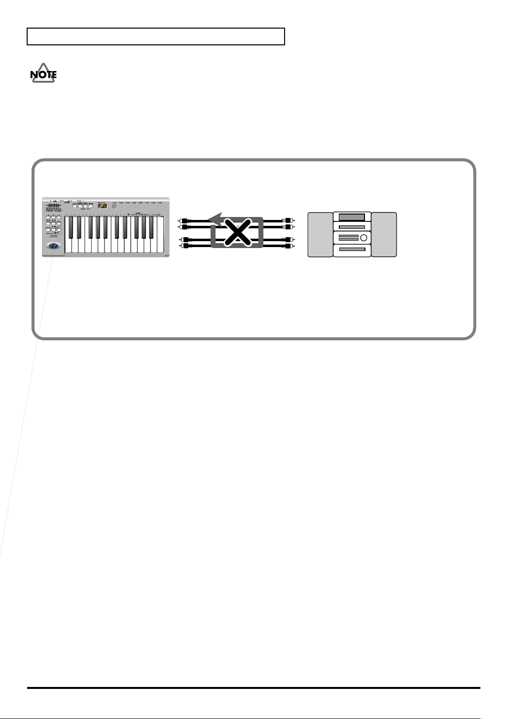
Use audio functionality
Don’t connect anything to input jacks you are not using.
Howling could be produced depending on the location of microphones relative to speakers.
This can be remedied by:
1.Changing the orientation of the microphone (s)/ 2.Relocating microphone (s) at a greater
distance from speakers/ 3.Lowering volume levels.
Be careful of looped connections
fig.loop
Example of loop connecttion
INPUT
LINE OUT
Audio amp
(Cassette deck,
Record Player)
OUTPUT
LINE IN
If the PCR-1 is connected as shown above to a device that outputs (“thru-s”) the input audio
(such as a cassette player that is in recording mode), turning on the Input monitor switch will
cause the sound to loop between the PCR-1 and the other device, causing oscillation and
producing an unexpectedly high volume. Be aware that such connections may cause the system
to malfunction, or your speakers to be damaged.
48
Page 49

Use audio functionality
Digitally recording sound from your computer
fig.digital.e
Connections
Use an optical digital cable to connect your recording device to the
* Signals input through the PCR-1's input jacks cannot be directly output from the digital output jack.
The digital output jack always outputs only the audio signal that is being sent from the computer.
Digital output jack
.
Setting the Sampling frequency
Set your audio playback software, the PCR-1, and your digital recording device (e.g., MD or
DAT) to the same
Whenever you’ve changed the sampling frequency, you must exit any applications you are
using, disconnect the USB cable from the PCR-1, then connect it again.
* The PCR-1 does not support professional digital audio formats.
Don’t connect anything to input jacks you are not using.
sampling frequency
(p. 96).
49
Page 50

Use MIDI functionality
Table of operating modes
You can switch modes at any time, as shown below.
Mode Switching modes Explanation
PLAY mode
(p. 51)
When you turn on the power, the PCR-1 will
start up in PLAY mode.
Transmit MIDI messages
by playing the keyboard
or operating the controllers.
MIDI Channel mode
(MIDI CH)
(p. 53)
Program Change mode
(PROGRAM CHANGE)
(p. 56)
Bank mode
(BANK)
(p. 57)
Panic mode
(PANIC)
(p. 58)
Memory mode
(MEMORY)
(p. 59)
Press the
Press the
it is lit, and then
press the
CHANGE]
Press the
it is lit, and then
press the
SEL]
Simultaneously,
Press the
and the
Press the
]
.
[MIDI CH]
[SHIFT]
[PGM
.
[SHIFT]
[BANK
.
[MIDI CH]
[EDIT]
[MEMORY
.
so
so
.
Set the transmit channel
(
current channel
for the keyboard and
bender lever.
Transmit program change
messages on the
channel
Transmit bank select messages (MSB, LSB) on the
current channel
Stop “stuck” notes or other problems with the
sound on a connected
MIDI sound module.
Recall a memory set from
internal memory into the
current memory
(p. 53).
p. 53)
current
(p. 53).
(p. 88).
50
Snapshot mode
(SNAPSHOT)
(p. 60)
Edit mode
(EDIT)
(p. 61)
Simultaneously,
Press the
RY]
CH]
Press the
[MEMO-
and the
[EDIT]
[MIDI
Transmit the current values of controllers (
R8]
or
[S1–S8]
.
Assign MIDI messages to
the controllers, transmit/
receive bulk data, or make
system settings.
[R1–
) at once.
You are returned to Play mode once a setting or a process has been completed within the other
modes. If you want to return to Play mode without completing a setting or operation, press the
button for the current mode (i.e., the button that is lit). Alternatively, press the
[CANCEL]
button. The setting you were in the process of making will be discarded.
Page 51

Startup mode
fig.connect-out1
PLAY mode
When you power up the PCR-1, it will start up in PLAY mode.
In PLAY mode, playing the keyboard will transmit note messages to play the connected MIDI
device.
The display will show the
In PLAY mode, you can play the keyboard to produce sound on a connected sound module,
and also use various other functions, such as operating the bender switch to change the pitch
of the currently sounding note (Pitch Bend), using the modulation button to add vibrato
(Modulation), or switching the octave (Octave Shift).
current channel
Use MIDI functionality
(p. 53).
In order to send MIDI messages from the PCR-1 to your application, perform the following
steps.
1
Set the MIDI channel the PCR-1 will use to transmit to the same channel on the application is
using to receive on.
Use MIDI Channel mode to set the
(➝MIDI Channel mode (MIDI CH)
2
Select a
(➝”Selecting Sounds on a Sound Module”
3
Once you have finished making settings, try playing the keyboard.
When you play the keyboard in
* Since the PCR-1 does not contain a sound generator, you cannot play MIDI data using the PCR-1 alone.
sound
on your
MIDI sound module
MIDI transmit channel
(p. 53)).
.
(p. 55)).
PLAY mode
, MIDI messages are sent to the application.
.
51
Page 52

Use MIDI functionality
Features Useful When Playing
Applying Pitch
Changes to Notes
(Pitch Bend)
Modifying the Sound
of Notes
(Modulation)
Changing Octaves
(Octave Shift)
Transpose the Pitch
of the Keyboard
(Transpose)
fig.MEMO
Move the
apply subtle pitch changes to notes.
PITCH BEND TIME
reach its maximum after the
* The amount of pitch change ("bend range") depends on the settings of your
Pressing the
the sound in real time (usually by adding a vibrato effect).
MODULATION SETTING
(CC#01) transmitted when you press the
* The type of change this produces in the sound depends on the settings of your
You can press
keyboard (the Octave Shift function). This lets you play a wider range of notes
than would normally be accessible from the 25 keys.
Press
to lower the range an additional octave. Permissible settings for this range from
-4 to 5 octaves.
*
* If you simultaneously press
You can press
to transpose the keyboard in semitone steps (the Transpose function).
You can transpose the pitch in a range of -12–12 (semitones).
* If you press and hold
* If you hold down
BENDER Switch
sound module.
Modulation Button
sound module.
[OCTAVE -]
[OCTAVE -]
[OCTAVE -] or [OCTAVE +]
setting.
setting will be reset to 0, restoring the normal pitch range of the keyboard.
according to the current Transpose setting.
[OCTAVE +]
once to lower the pitch range one octave. Press it once again
[TRANSPOSE]
, the Transpose setting will be reset to 0.
(left or right) to transmit
(p. 97) specifies the time it is to take for the
bender switch
will transmit
(p. 97) specifies the value of the
or
[OCTAVE +]
will light according to the current Octave Shift
[OCTAVE -]
+
[OCTAVE +]
[TRANSPOSE], [OCTAVE -]
[TRANSPOSE]
has been pressed.
Modulation Button
to raise or lower the pitch range of the
and
and simultaneously press
Pitch Bend
Modulation
[OCTAVE +]
or
[TRANSPOSE] + [OCTAVE -]
messages, changing
Modulation message
.
, the Octave Shift
or
[OCTAVE +]
messages, and
pitch bend
will light
[OCTAVE -]
While playing the keyboard, move the Bender Switch to the left to lower the pitch of the
currently selected patch, or to the right to raise its pitch. This is known as
pitch bend
.
You can also apply vibrato by gently pressing the Modulation button. This is known as
modulation
.
If you press the Modulation Button and the same time move Bender Switch to the right or left,
you can apply both effects at once.
to
and
Octave Shift
and
Transpose
can be set independently.
To switch the PCR-1 to PLAY mode...
The PCR-1 will automatically start up in PLAY mode when you connect the PCR-1 to your
computer by USB cable.
To return to PLAY mode from another mode (➝Setting the MIDI Transmit Channel
press the button of the current mode (i.e., the button that is lit).
Alternatively, you can press the
[CANCEL]
making will be cancelled.
52
(p. 53)),
button. In this case, the setting you had been
Page 53

Setting the MIDI Transmit Channel
Use MIDI functionality
To control your sound module, set the PCR-1's
selected on your sound module. Use MIDI Channel mode to set the
MIDI Channel mode (
fig.MIDIch-1
MIDI CH)
current channel
to the MIDI receive channel that's
current channel
.
fig.MIDIch
1
Press the
The
channel setting.
[MIDI CH]
[MIDI CH]
button.
button will light. The display will show the current
53
Page 54

Use MIDI functionality
* The setting will be cancelled if you press another button instead of the
[ENTER]
button.
OMNI
If you turn the Omni setting ON, all messages will be transmitted on the current channel
regardless of the channel that is specified for each controller.
Also, all messages will be transmitted to the KEYBOARD PORT SET (p. 94) regardless of the
port that is specified for each controller.
fig.edt
1. Press the [EDIT] button.
The display will indicate “EDT”.
fig.omn
2. Press the [OMNI] key.
The display will blink “OMN”.
3. Confirm what’s indicated and press the [ENTER] button.
4. The display will show the current setting.
0 OMNI OFF
1 OMNI ON
5. Use the [DEC] [INC] buttons or the [0] or [1] keys to select the mode.
6. Press the [ENTER] button.
Messages will be transmitted on the channel and port specified
for each controller.
Messages will be transmitted on the current channel from the
Keyboard Port, regardless of the channel and port specified for
each controller.
Setting the input mode
fig.hexdec
If you are not in Play mode, you can use one of two ways to input a numerical
value into the PCR-1; Decimal input mode or Hexadecimal input mode.
If you want to input decimal numbers, press the [DECIMAL] button. If you
want to input hexadecimal numbers, press the [HEX] button. When you
connect the PCR-1 to your computer by USB cable, the PCR-1 will start up in
Decimal mode.
Decimal and hexadecimal numbers correspond as follows.
Decimal:0–127
Hexadecimal:00–7F
However, for MIDI CH and PROGRAM CHANGE, the values are as follows.
Decimal Hexadecimal
MIDI CH 1–16 00–0F
PROGRAM CHANGE 1–128 00-7F
* Normally, the display will show three digits when using Decimal input mode. For this reason, there will
be no indication of the parameter you are now inputting, and you may lose track of what you are doing.
If this occurs, you can temporarily switch back to Hexadecimal mode to check the parameter you are
inputting. Then switch back to Decimal mode and continue.
54
Page 55

Use MIDI functionality
Selecting Sounds on a Sound Module
(Sending Program Change / Bank Select Massages)
To select a sound on your MIDI sound module, transmit a Program Change in
Change mode
To select a sound from a different bank, first use
that switches the bank. Then transmit a program change.
* You must send the Bank Select message before sending the Program Change message.
.
Bank mode
to transmit a Bank Select message
Program
What is a bank?
MIDI sound modules organize their numerous sounds in various groups according to the
category of sound.
These groups are called “banks.”
Program Change messages can only select sounds within the same bank, but by using these in
conjunction with Bank Select messages, you can select different variations of sound.
* The way in which sounds are organized will differ for each sound module. For details, refer to the owner’s
manual of the sound module you are using.
•
Program Change Mode (PROGRAM CHANGE)
•
Bank mode (BANK)
(p. 57)
(p. 56)
55
Page 56

Use MIDI functionality
Program Change Mode (
This mode lets you transmit a program change message on the
fig.PC-1_90
fig.program
1
Press the
[SHIFT]
button so it is lit.
PROGRAM CHANGE)
current channel
(p. 53).
2
Press the
The
program change that was transmitted most recently.
* The
1Use the
change you want to transmit.
DEC
INC
00–0F
3
Press the
The
The setting will be cancelled if you press another button instead of the
[PGM CHANGE]
[PGM CHANGE]
[HEX]
or
[DECIMAL]
[DEC] [INC]
Change the current value by -1
Change the current value by +1
The input value
HEX
DECIMAL
[ENTER]
program change
button will light. The display will indicate the
buttons or the
...00–7F
button.
has now been transmitted.
button.
button will also light according to the input mode (p. 54).
[0] – [F]
...1–128
keys of the keyboard to specify the program
[ENTER]
button.
56
Page 57

Use MIDI functionality
Bank mode (
This mode lets you transmit a bank select (MSB, LSB) message on the
program change message you most recently transmitted (specified) in
(p. 56) will also be transmitted following the bank select message.
fig.BANK2_90
fig.bank
1
Press the
BANK)
[SHIFT]
button so it is lit.
current channel
Program Change mode
. The
2
Press the
The
transmitted bank select (MSB) value.
* The
fig.BANK-2
3
First, specify the
Use the
bank select MSB that you want to transmit.
4
Press the
The setting will be cancelled if you press another button instead of the
fig.BANK-3
5
Next, specify the bank select LSB (CC#32).
The display will indicate the most recently transmitted bank select (LSB) value.
Use the
bank select LSB that you want to transmit.
6
Press the
The bank select has now been transmitted.
[BANK SEL]
[BANK SEL]
[HEX]
or
[DECIMAL]
[DEC] [INC]
[ENTER]
[DEC] [INC]
[ENTER]
button.
will light. The display will indicate the most recently
button will also light according to the input mode (p. 54).
bank select MSB
buttons or the
button.
buttons or the
button.
(CC#00).
[0]
–
[F]
[0] – [F]
keys of the keyboard to specify the
keys of the keyboard to specify the
[ENTER]
button.
The setting will be cancelled if you press another button instead of the
[ENTER]
button.
57
Page 58

Use MIDI functionality
Transmitting a Reset message
(What to do if there are “stuck” MIDI notes)
If notes on a connected MIDI sound module become “stuck”, or if there is something wrong
with the sound, you can execute the Panic function to solve the problem.
When you execute the Panic function,
messages will be transmitted on all channels.
All sound off, All notes off
, and
Reset all controllers
Panic Mode (
fig.panic2_90
2
fig.panic
1
Simultaneously press the
The
[MIDI CH]
PANIC)
button and
1
[MIDI CH]
[EDIT]
button will light.
button and
[EDIT]
button.
58
2
Press the
The
The Panic function has now been executed.
[ENTER]
[MIDI CH]
button.
button and
[EDIT]
button will blink several times.
Page 59

Changing the Memory Sets
When the PCR-1 is shipped, its internal memory contains sixteen different settings. For details
on the contents of each memory number, refer to
You will use Memory mode to change the Memory sets.
Memory sets
Use MIDI functionality
(p. 100).
Memory mode (
fig.memory2_90
3
fig.memory
1
Press the
The
[MEMORY]
number that you selected most recently.
MEMORY)
21
[MEMORY]
button.
button will light. The display will indicate the memory
2
Use the
number that you want to recall.
3
Press the
The memory has now been recalled.
The setting will be cancelled if you press another button instead of the
For details on customizing (editing) the controller settings, refer to Assign MIDI messages
(EDIT) (p. 61).
If you edit the controller settings of a memory you recall, and want to keep your changes, you
must save the memory before powering down the PCR-1. For the procedure, refer to Saving a
memory set (SAVE) (p. 88).
[DEC] [INC]
[ENTER]
buttons or the
button.
[0] – [F]
keys of the keyboard to specify the memory
[ENTER]
button.
59
Page 60

Use MIDI functionality
Transmitting the current controller values all at once (SNAPSHOT)
Once you have set the various controllers to the desired settings, you can transmit a detailed
description of this state in the form of a “snapshot”. When you execute this function, the current
values of the controllers
[R1–R8]
or
[S1–S8]
will be transmitted.
* When the
S8] will be transmitted.
fig.MEMO
This is convenient when you want to record the state of these controllers together at the
beginning of a song in your sequencer, as the initial values.
[SHIFT]
button is off,
[R1–R8] will be transmitted. When the
Snapshot mode (SNAPSHOT)
fig.snap2_90
[SHIFT]
button is on,
[S1–
60
fig.snap
1
Simultaneously press the
The
[MEMORY]
2
Press the
The
[MEMORY]
The snapshot will be transmitted.
and
[ENTER]
button and
[MIDI CH]
button.
[MEMORY]
buttons will light.
[MIDI CH]
button and the
button will blink several times.
[MIDI CH]
button.
Page 61

Assign MIDI messages (EDIT)
You can assign the following functions to a controller.
You will use Edit mode to assign MIDI messages.
Use MIDI functionality
NOTE
AFTERTOUCH
CONTROL CHANGE
PROGRAM CHANGE
RPN
NRPN
Sys Ex
TEMPO (20-250)
NOTE ASSIGN
AFTERTOUCH ASSIGN
CONTROL CHANGE ASSIGN
PROGRAM CHANGE ASSIGN
RPN / NRPN ASSIGN
RPN / NRPN ASSIGN
Sys Ex. ASSIGN
TEMPO ASSIGN
(p. 63) You can copy assigned messages to
(p. 65)
(p. 74)
(p. 74)
(p. 77)
(p. 85)
(p. 68)
(p. 71)
another controller, or cancel an assignment. For details, refer to
ing a MIDI message assignment
(ASSIGN COPY)
ing a MIDI message assignment
(NO ASSIGN)
(p. 86) or
(p. 87).
* If you want to assign a single-byte system message (system realtime message, tune request) or a freely
specified message of up to 24 bytes, refer to
Sys Ex. ASSIGN
(p. 77).
Edit mode ( EDIT )
fig.EDIT2_90
Copy-
Cancel-
61
Page 62

Use MIDI functionality
Specifying the button mode
When you make Assign settings (p. 61) in Edit mode to assign a message to a button, you must
specify the operating mode of the button (button mode).
When you use a button as a controller, turning the button on will transmit the maximum
specified value, and turning it off will transmit the minimum value.
1. Press the [0] or [1] key to select either Latch mode or Toggle mode.
0 Latch mode
1 Toggle mode
2. Press the [ENTER] button.
Specifying the port
When you are making Assign settings (p. 61) in Edit mode and have selected Advanced mode,
you must specify the USB port to which the message assigned to the controller will be sent
when using a USB connection.
The setting will turn on when you press the button, and off
when you release it. The button will remain lit while you are
pressing it.
The setting will alternate on/off each time you press the button. The button will light when an On message is transmitted,
and will go dark when an Off message is transmitted.
1. Press a key [1] – [3] to select the port.
1 PORT 1 Messages will be sent to “PCR-1 1”
2 PORT 2 Messages will be sent to “PCR-1 2”
3 PORT 1, 2 Messages will be sent to both “PCR-1 1” and “PCR-1 2”
2. Press the [ENTER] button.
* For details on the port, refer to Input / output devices (p. 44).
62
Page 63

■
NOTE ASSIGN
Here’s how to assign a Note message to a controller. In addition to being used to play sounds,
note messages can also be used to control a sequencer.
Mode Keyboard Velocity Port
Basic mode
fig.edt2
1
Press the
The display will indicate “EDT.”
fig.r-1
2
Slightly move the controller to which you want to assign a Note message. In the
case of a button, press that button.
The display will indicate the number of the selected controller.
[EDIT]
Use MIDI functionality
button.
3
Verify that the display shows the correct controller number, and press the
fig.nt0
4
Press an
to get "NT0" to appear in the display.
fig.c
5
Press the
The display will indicate “C–.”
6
Input the channel. Use the
fig.n
7
Press the
The display will indicate “N–.”
8
Input the note number. Use the
number.
ASSIGNABLE FUNCTION
[ENTER]
[ENTER]
button.
[DEC] [INC]
button.
[DEC] [INC]
key ( ) on the keyboard enough times
buttons or the
buttons or the
[0]–[F]
[ENTER]
keys to specify the channel.
[0] – [F]
keys to specify the note
button.
9
Press the
10
If you are making an assignment for a button, specify the button mode.
(➝Specifying the button mode
[ENTER]
button.
(p. 62))
63
Page 64

Use MIDI functionality
Advanced mode 1
Advanced mode 1 of NOTE ASSIGN lets you specify the velocity value in addition to the items
of Basic mode.
1.
Press the
2.
Slightly move the controller to which you want to assign a Note message. In the case of a
button, press that button.
The display will indicate the number of the selected controller.
3.
Verify that the display indicates the correct controller, and press the
4.
Using the
in the display, then press the
5.
Press the
6.
Input the channel.
7.
Press the
8.
Input the note number.
fig.v
9.
Press the
The display will indicate “V–.”
10.
Input the velocity.
fig.p
11.
Press the
The display will indicate “P–.”
12.
Specify the output port. (➝Specifying the port
[EDIT]
button.
ASSIGNABLE FUNCTION
[1]
key of the keyboard.
[ENTER]
[ENTER]
[ENTER]
[ENTER]
button.
button.
button.
button.
[ENTER]
button.
keys ( ) on the keyboard, get "NT0" to appear
*1 Reference
(p. 62))
*1 Reference
13.
If you are making an assignment for a button, specify the button mode.
(➝Specifying the button mode
• If you set
[S1] – [S8] , [R1] – [R8]
(p. 62))
to NOTE ASSIGN, setting the controller to the maximum
position will transmit the specified velocity value.
• If you assign this to
[B1] – [B6]
, the specified velocity value will be transmitted when you
turn the controller on. When you turn the controller off, a note message with a velocity value
of 0 will be transmitted.
*1 The -- area displays the currently set value. If it has not been set, the default setting will be displayed. Even if you change the type or mode
64
of the MIDI message that is assigned, the default setting will be displayed. This will be lit if the value is the same as the currently set value,
or will blink if the value is different.
Page 65

■
AFTERTOUCH ASSIGN
Here’s how to assign an Aftertouch message to a controller.
Mode Keyboard Message Value range Port
Basic mode 0 Channel Pressure 0-127 (00–7FH) Port 1
Advanced mode 1 1 Channel Pressure Assignable Assignable
Advanced mode 2 2 Polyphonic Key Pressure 0-127 (00–7FH) Port 1
Advanced mode 3 3 Polyphonic Key Pressure Assignable Assignable
Basic mode
fig.edt2
1
Press the
The display will indicate “EDT.”
fig.r-1
2
Slightly move the controller to which you want to assign an Aftertouch
message. In the case of a button, press that button.
The display will indicate the number of the selected controller.
[EDIT]
button.
Use MIDI functionality
3
Verify that the display shows the correct controller number, and press the
fig.at1
4
Press an
to get "AT0" to appear in the display.
fig.c
5
Verify that the display is correct, and press the
The display will indicate “C–”.
6
Input the channel. Use the
7
Press the
8
If you are making an assignment for a button, specify the button mode.
(➝Specifying the button mode
ASSIGNABLE FUNCTION
[DEC] [INC]
[ENTER]
button.
(p. 62))
key ( ) on the keyboard enough times
[ENTER]
buttons or the
button.
[0] – [F]
[ENTER]
keys to specify the channel.
button.
*1 Reference
*1 The -- area displays the currently set value. If it has not been set, the default setting will be displayed. Even if you change the type or mode
of the MIDI message that is assigned, the default setting will be displayed. This will be lit if the value is the same as the currently set value,
or will blink if the value is different.
65
Page 66

Use MIDI functionality
Advanced mode 1–3
Advanced mode 1 of AFTERTOUCH ASSIGN lets you specify the upper and lower limits of the
aftertouch value in addition to the items of Basic mode. Advanced modes 2 and 3 let you specify
an aftertouch message for an individual note (Polyphonic Key Pressure) instead of specifying
the channel.
1.
fig.at1
Press the
2.
Slightly move the controller to which you want to assign an Aftertouch message. In the
case of a button, press that button.
The display will indicate the number of the selected controller.
3.
Verify that the display indicates the correct controller, and press the
4.
Using the
"AT0" to appear in the display, then press the
The display will indicate the selected mode.
5.
Press the
6.
Input the channel.
7.
Press the
[EDIT]
[ENTER]
[ENTER]
button.
ASSIGNABLE FUNCTION
button.
button.
[ENTER]
keys ( ) on the keyboard, get
[1]
-
[3]
key of the keyboard.
button.
8.
If you are using Advanced modes 2 or 3, input the note number.
9.
If you are using Advanced modes 2 or 3, press the
10.
If you are using Advanced modes 1 or 3, specify the upper limit and lower limit of the
value as described in
and specify the output port.
11.
If you are using Advanced modes 1 or 3, specify the output port.(➝Specifying the port
(p. 62))
12.
If you are making an assignment for a button, specify the button mode.
(➝Specifying the button mode
Specifying the range of values (upper and lower limits)
(p. 62))
[ENTER]
button.
(p. 67) ,
66
Page 67

Specifying the range of values (upper and lower limits)
*1 Reference
If in Edit mode you selected an Assign type (p. 61) that lets you specify the range of values, you
will need to specify the upper limit and lower limit of the value.
* Normally, when using Decimal input mode, the value you are specifying appears in the display as a three
digit number. This means that there is no indication of which parameter you are currently entering, so
you may lose track of what you are doing. If this occurs, you can temporarily switch to Hex input mode
to check the parameter that you are now inputting. Then switch back to Decimal input mode and
continue. (
fig.max
1. The following display will appear.
➝
Setting the input mode (p. 54))
Use MIDI functionality
2. Use the [DEC] [INC] buttons or the [0] – [F] keys to specify the upper limit.
fig.min
3. Press the [ENTER] button.
The following display will appear.
4. Use the [DEC] [INC] buttons or the [0] – [F] keys to specify the
lower limit.
5. Press the [ENTER] button.
*1 Reference
*1 The -- area displays the currently set value. If it has not been set, the default setting will be displayed. Even if you change the type or mode
of the MIDI message that is assigned, the default setting will be displayed. This will be lit if the value is the same as the currently set value,
or will blink if the value is different.
67
Page 68

Use MIDI functionality
■
CONTROL CHANGE ASSIGN
Here’s how to assign a control change message to a controller.
Mode keyboard Value range Port
Basic mode 0 00–7FH PORT 1
Advanced mode 1 1 Assignable Assignable
Advanced mode 2 2 Simulates a rotary encoder Assignable
Basic mode
fig.edt2
1
Press the
The display will indicate “EDT”.
fig.r-1
2
Slightly move the controller to which you want to assign a Control Change
message. In the case of a button, press that button.
The display will indicate the number of the selected controller.
[EDIT]
button.
3
Confirm what’s indicated, and press the
fig.cc0
4
Press an
to get "CC0" to appear in the display.
fig.c
5
Confirm what’s indicated, and press the
The display will indicate “C–”.
6
Input the channel. Use the
fig.n
7
Press the
The display will indicate “N–”.
8
Use the
9
Press the
ASSIGNABLE FUNCTION
[ENTER]
[DEC] [INC]
[ENTER]
button.
buttons or the
button.
key ( ) on the keyboard enough times
[DEC] [INC]
[0] – [F]
[ENTER]
[ENTER]
buttons or the
button.
button.
[0] – [F]
keys to specify the control change number.
keys to specify the channel.
*1 Reference
*1 Reference
10
If you are making an assignment for a button, specify the button mode.
(➝Specifying the button mode
*1 The -- area displays the currently set value. If it has not been set, the default setting will be displayed. Even if you change the type or mode
68
of the MIDI message that is assigned, the default setting will be displayed. This will be lit if the value is the same as the currently set value,
or will blink if the value is different.
(p. 62))
Page 69

Advanced mode 1
Advanced mode 1 of CONTROL CHANGE ASSIGN lets you specify the upper and lower limits
of the control change value in addition to the items of Basic mode.
1.
fig.p
Press the
2.
Slightly move the controller to which you want to assign a Control Change message. In
the case of a button, press that button.
The display will indicate the number of the selected controller.
3.
Confirm what’s indicated, and press the
4.
Using the
in the display, then press the
The display will indicate “CC1”.
5.
Press the
6.
Input the channel.
7.
Press the
8.
Input the control change number.
9.
Press the
10.
Specify the range of values. (➝Specifying the range of values (upper and
lower limits)
The display will indicate “P–”.
[EDIT]
button.
ASSIGNABLE FUNCTION
[1]
key of the keyboard.
[ENTER]
[ENTER]
[ENTER]
button.
button.
button.
(p. 67))
[ENTER]
button.
keys ( ) on the keyboard, get "CC0" to appear
Use MIDI functionality
*1 Reference
11.
Specify the output port. (➝Specifying the port
12.
If you are making an assignment for a button, specify the button mode.
(➝Specifying the button mode
(p. 62))
(p. 62))
*1 The -- area displays the currently set value. If it has not been set, the default setting will be displayed. Even if you change the type or mode
of the MIDI message that is assigned, the default setting will be displayed. This will be lit if the value is the same as the currently set value,
or will blink if the value is different.
69
Page 70

Use MIDI functionality
Advanced mode 2
Advanced mode 2 simulates the operation of a conventional rotary encoder. If this is assigned
to a controller, moving that controller toward the right (upward) of center will have the same
effect as turning the encoder clockwise, and moving the controller toward the left (downward)
of center will have the same effect as turning the encoder counterclockwise. As the controller is
moved further away from the center, the result will be the same as if the rotary encoder were
moved more quickly.
You can assign advanced mode 2 to a button, but it will not function.
1.
Press the
2.
Slightly move the controller to which you want to assign a Control Change message.
The display will indicate the number of the selected controller.
3.
Confirm what’s indicated, and press the
4.
Using the
in the display, then press the
The display will indicate “CC2”.
5.
Press the
6.
Input the channel.
[EDIT]
button.
ASSIGNABLE FUNCTION
[2]
key of the keyboard.
[ENTER]
button.
[ENTER]
button.
keys ( ) on the keyboard, get "CC0" to appear
fig.p
7.
Press the
8.
Input the control change number. Use the
[ENTER]
button.
specify the control change number.
9.
Press the
[ENTER]
button.
The display will indicate “P–”.
10.
Specify the output port. (➝Specifying the port
[DEC] [INC]
(p. 62))
buttons or the
[0] – [F]
keys to
*1 Reference
*1 The -- area displays the currently set value. If it has not been set, the default setting will be displayed. Even if you change the type or mode
70
of the MIDI message that is assigned, the default setting will be displayed. This will be lit if the value is the same as the currently set value,
or will blink if the value is different.
Page 71

■
PROGRAM CHANGE ASSIGN
Here’s how to assign a program change message to a controller.
Mode Number Effect Bank Port
Basic mode 0 Fixed value Not output PORT 1
Advanced mode 1 1 Assignable range of values Not output PORT 1
Advanced mode 2 2 Fixed value Output Assignable
Advanced mode 3 3 PC DEC Not output PORT 1
Advanced mode 4 4 PC INC Not output PORT 1
Basic mode
fig.edt2
1
Press the
The display will indicate “EDT.”
fig.r-1
2
Slightly move the controller to which you want to assign a Program Change
message. In the case of a button, press that button.
The display will indicate the number of the selected controller.
[EDIT]
button.
Use MIDI functionality
3
Confirm what’s indicated, and press the
fig.pc0
4
Press an
to get "PC0" to appear in the display.
fig.c
5
Confirm what’s indicated, and press the
The display will indicate “C–”.
6
Input the channel. Use the
fig.n
7
Press the
The display will indicate “N–”.
8
Use the
9
Press the
ASSIGNABLE FUNCTION
[ENTER]
[DEC] [INC]
[ENTER]
button.
buttons or the
button.
key ( ) on the keyboard enough times
[DEC] [INC]
[0]
[ENTER]
[ENTER]
buttons or the
–
[F]
button.
button.
[0] – [F]
keys to specify the program change number.
keys to specify the channel.
*1 Reference
*1 Reference
* If you assign Basic mode to
position will transmit the assigned program change messages.
*1 The -- area displays the currently set value. If it has not been set, the default setting will be displayed. Even if you change the type or mode
of the MIDI message that is assigned, the default setting will be displayed. This will be lit if the value is the same as the currently set value,
or will blink if the value is different.
[S1] – [S8]
or
[R1] – [R8]
, moving the controller up to the maximum
71
Page 72

Use MIDI functionality
Advance mode 1, 2
Advanced mode 1 of PROGRAM CHANGE ASSIGN lets you specify the upper and lower
limits of the program change value. Advanced mode 2 lets you transmit BANK LSB/MSB
settings in addition to the program change.
1.
Press the
2.
Slightly move the controller to which you want to assign a Program Change message. In
the case of a button, press that button. The display will indicate the number of the selected
controller.
3.
Confirm what’s indicated, and press the
Advanced mode 1
—Specifying the range of values
4.
Using the
in the display, then press the
5.
Press the
6.
Input the channel.
7.
Press the
[EDIT]
button.
ASSIGNABLE FUNCTION
[1]
key of the keyboard.
[ENTER]
[ENTER]
button.
button.
[ENTER]
button.
keys ( ) on the keyboard, get "PC0" to appear
8.
Specify the range of values. (➝Specifying the range of values (upper and lower limits)
(p. 67))
Advanced mode 2
—Transmitting bank data
4.
Using the
in the display, then press the
5.
Press the
6.
Input the channel.
7.
Press the
fig.bank-2
8.
Specify the bank select MSB (CC#00). Use the
–
[F]
keys to specify the MSB.
9.
Press the
fig.BANK-3
10.
Specify the bank select LSB (CC#32). Use the
–
[F]
keys to specify the LSB.
11.
Press the
12.
Input the program change number.
fig.p
13.
Press the
The display will indicate “P–”.
14.
Specify the output port. (➝Specifying the port
ASSIGNABLE FUNCTION
[2]
key of the keyboard.
[ENTER]
[ENTER]
[ENTER]
[ENTER]
[ENTER]
button.
button.
button.
button.
button.
keys ( ) on the keyboard, get "PC0" to appear
[DEC] [INC]
[DEC] [INC]
(p. 62))
buttons or the
buttons or the
[0]
*1 Reference
[0]
*1 Reference
*1 Reference
*1 The -- area displays the currently set value. If it has not been set, the default setting will be displayed. Even if you change the type or mode
72
of the MIDI message that is assigned, the default setting will be displayed. This will be lit if the value is the same as the currently set value,
or will blink if the value is different.
Page 73

Advanced modes 3 and 4
Advanced mode 3 lets you assign the Program Change Decrement function (
controller.
Advanced mode 4 lets you assign the Program Change Increment function (
controller.
1.
Press the
2.
Slightly move the controller to which you want to assign Program Change DEC/INC. In
the case of a button, press that button.
The display will indicate the number of the selected controller.
3.
Confirm what’s indicated, and press the
4.
Using the
in the display, then press the
5.
Press the
[EDIT]
button.
ASSIGNABLE FUNCTION
[3] or [4]
[ENTER]
button.
[ENTER]
keys ( ) on the keyboard, get "PC0" to appear
key of the keyboard.
button.
Program Change Decrement function (PC DEC)
This transmits a program change that is one less than the previously transmitted program
change number.
PC DEC
PC INC
Use MIDI functionality
) to a
) to a
Program Change Increment function (PC INC)
This transmits a program change that is one greater than the previously transmitted program
change number.
The PC DEC or PC INC is transmitted on the current channel, just as in Program Change Mode
(PROGRAM CHANGE) (p. 56). The value that is actually transmitted will appear in the display.
• In the explanation here, the “previously transmitted program number” refers to the one that
was last transmitted by Advanced Mode 3 or 4 or in Program Change Mode (PROGRAM
CHANGE) (p. 56).
• Program changes transmitted by basic mode or advanced modes 1 and 2 will not affect the
increment/decrement functions.
73
Page 74

Use MIDI functionality
■
RPN / NRPN ASSIGN
Here’s how you can assign an RPN or NRPN message to a controller.
Mode Keyboard
Basic mode 0 0-127 (00–7FH) Not transmitted PORT 1
Advanced mode 1 1 Assignable 0-127 (00–7FH) Assignable
fig.edt2
1
Press the
The display will indicate “EDT”.
fig.r-1
2
Slightly move the controller to which you want to assign an RPN or NRPN
message. In the case of a button, press that button.
The display will indicate the number of the selected controller.
3
Confirm what’s indicated, and press the
fig.rp0
4
Press an
to get "RP0" to appear in the display.
fig.np0
* If you want to assign an NRPN message, press the
is the same as for RPN.
[EDIT]
button.
ASSIGNABLE FUNCTION
Data entry MSB
(CC#6) range
[ENTER]
key ( ) on the keyboard enough times
button.
[NRPN]
Data entry LSB
(CC#38) range
key. The following procedure
Port
fig.c
5
Confirm what’s indicated, and press the
The display will blink “C–”.
6
Input the channel. Use the
7
Press the
fig.BANK-2
8
Use the
(CC#101) or NRPN MSB (CC#99).
*1 The -- area displays the currently set value. If it has not been set, the default setting will be displayed. Even if you change the type or mode
74
of the MIDI message that is assigned, the default setting will be displayed. This will be lit if the value is the same as the currently set value,
or will blink if the value is different.
[ENTER]
[DEC] [INC]
button.
[DEC] [INC]
buttons or the
[ENTER]
buttons or the
[0] – [F]
keys to specify the RPN MSB
button.
[0] – [F]
*1 Reference
keys to specify the channel.
*1 Reference
Page 75

9
Press the
fig.BANK-3
10
Use the
(CC#100) or NRPN LSB (CC#98).
11
Press the
12
If you are making an assignment for a button, specify the button mode.
[ENTER]
[DEC] [INC]
[ENTER]
button.
buttons or the
button.
[0] – [F]
keys to specify the RPN LSB
Use MIDI functionality
*1 Reference
(➝Specifying the button mode
(p. 62))
*1 The -- area displays the currently set value. If it has not been set, the default setting will be displayed. Even if you change the type or mode
of the MIDI message that is assigned, the default setting will be displayed. This will be lit if the value is the same as the currently set value,
or will blink if the value is different.
75
Page 76

Use MIDI functionality
Advanced mode
In Advanced mode for RPN/NRPN, you can specify the upper and lower limit of the data entry
MSB (CC#06) value when the RPN/NRPN message is transmitted, as well as the various
settings available in Basic mode.
1.
Press the
2.
Slightly move the controller to which you want to assign the RPN or NRPN message. In
the case of a button, press that button.
The display will indicate the number of the selected controller.
3.
Confirm what’s indicated, and press the
4.
Using the
in the display, then press the
[EDIT]
button.
ASSIGNABLE FUNCTION
[1]
key of the keyboard.
[ENTER]
button.
keys ( ) on the keyboard, get "RP0" to appear
* If you want to assign an NRPN message, press the
as for RPN.
5.
Press the
6.
Input the channel. Use the
7.
Press the
8.
Use the
[ENTER]
[ENTER]
[DEC] [INC]
button.
[DEC] [INC]
button.
buttons or the
NRPN MSB (CC#99).
9.
10.
Press the
Use the
[ENTER]
[DEC] [INC]
button.
buttons or the
NRPN LSB (CC#98).
11.
fig.p
Press the
12.
Specify the lower limit of the data entry MSB (CC#06) value. (➝Specifying
[ENTER]
button.
the range of values (upper and lower limits)
The display will indicate “P–.”
13.
Specify the output port. (➝Specifying the port
14.
If you are making an assignment for a button, specify the button mode.
(➝Specifying the button mode
buttons or the
[0] – [F]
[0] – [F]
(p. 62))
[NRPN]
key. The following procedure is the same
[0] – [F]
keys to specify the channel.
keys to specify the RPN MSB (CC#101) or
keys to specify the RPN LSB (CC#100) or
(p. 67))
*1 Reference
(p. 62))
*1 The -- area displays the currently set value. If it has not been set, the default setting will be displayed. Even if you change the type or mode
76
of the MIDI message that is assigned, the default setting will be displayed. This will be lit if the value is the same as the currently set value,
or will blink if the value is different.
Page 77

■
Sys Ex. ASSIGN
Here’s how you can assign a system exclusive message to a controller. Advanced mode 2 lets
you assign a single-byte system message (System realtime message, tune request).
Advanced modes 3 and 4 let you assign any desired message. (Input up to 24 bytes)
Use MIDI functionality
[EDIT]
Key-
board
button.
Mode Value range Required ending Notes/restrictions
Single byte system message
Any desired
MIDI message
Any desired
MIDI message
– –
Default range Specified number of bytes
Assignable Specified number of bytes
Sys Ex. ASSIGN items
[0–5, 7, 9, D, E] [DATA][CHECKSUM]
tons are invalid
[CHECKSUM]
invalid
[CHECKSUM]
invalid
Mode
Basic mode 0 Sys Ex. message Default range Input F7 1st byte fixed at F0
Advanced mode 1 1 Sys Ex. message Assignable Input F7 1st byte fixed at F0
Advanced mode 2 2
Advanced mode 3 3
Advanced mode 4 4
Sys Ex. ASSIGN can calculate the checksum automatically, and lets you specify a variable (data)
range or embed a channel/block number within the message. (
In Sys Ex. ASSIGN, the input mode will be HEX mode.
fig.edt2
1
Press the
The display will indicate “EDT”.
fig.r-1
2
Slightly move the controller to which you want to assign the system exclusive
message. In the case of a button, press that button.
The display will indicate the number of the selected controller.
but-
button is
button is
(p. 79))
3
Confirm what’s indicated, and press the
fig.se0
4
Press an
to get "SE0" to appear in the display.
5
If you want to select an Advanced mode, press a key from
The selected mode will blink in the display.
6
Confirm what’s indicated, and press the
Then continue with the procedure described in Basic mode or Advanced mode (p. 78).
For some actual examples of settings, refer to
messages
ASSIGNABLE FUNCTION
(p. 82).
[ENTER]
key ( ) on the keyboard enough times
[ENTER]
button.
[1]
to
[4]
.
button.
Examples of assigning system exclusive
77
Page 78

Use MIDI functionality
For Basic mode or Advanced mode 1
The display will blink “F0”, which is the first byte (starting status byte) of a system exclusive
message. (This cannot be changed.)
fig.f0
7.
Confirm what’s indicated, and press the
8.
Use the
9.
Press the
10.
Input the third and subsequent bytes in the same way.
11.
When you have finished inputting the message, use the keyboard to enter
[0] – [F]
[ENTER]
keys to input the second byte.
button.
specifying the ending status byte “F7”.
12.
Press the
13.
If Advanced mode1, specify the range of values. (➝Specifying the range of values
(upper and lower limits)
14.
Specify the output port. (➝Specifying the port
15.
If you are making an assignment for a button, specify the button mode.
(➝Specifying the button mode
[ENTER]
button.
(p. 67))
(p. 62))
For Advanced mode 2
fig.f0
The display will indicate “F-.”
[ENTER]
(p. 62))
button.
[F]
and
[7]
,
7.
Use the
[6], [8], [A] – [C], [F]
8.
Press the
9.
Specify the output port. (➝Specifying the port
[ENTER]
button.
For Advanced modes 3 or 4
fig.BANK-3
The display will indicate “L–”.
7.
Use the
bytes you want to input.
8.
Press the
9.
Use the
10.
Press the
11.
Input the second and subsequent bytes in the same way.
12.
After you have input the number of bytes you specified in step 7, the PCR-1 will check
whether the messages you’ve input are indeed valid MIDI messages. If there is a problem,
the display will indicate “ERR”.
In this case, you should press the
you can input the values over again.
13.
If Advanced mode4, specify the range of values. (➝Specifying the range of values
(upper and lower limits)
14.
Specify the output port. (➝Specifying the port
15.
If you are making an assignment for a button, specify the button mode.
(
[0] – [F]
[0] – [F]
keys of the keyboard to specify the number (decimal) of
[ENTER]
button.
keys to input the first byte.
[ENTER]
button.
(p. 67))
➝Specifying the button mode (p. 62))
keys to specify the system message.
(p. 62))
[ENTER]
button, which takes you back to step 7, where
(p. 62))
*1 Reference
*1 The -- area displays the currently set value. If it has not been set, the default setting will be displayed. Even if you change the type or mode
78
of the MIDI message that is assigned, the default setting will be displayed. This will be lit if the value is the same as the currently set value,
or will blink if the value is different.
Page 79

■
Sys Ex. ASSIGN items
•
Specifying the checksum
•
Specifying the location of the data
•
Inputting channel/block data
Specifying the checksum
The PCR-1 can automatically calculate the checksum of a system exclusive message and embed
it in the message. In order to use this function, you must use the following procedure to specify
the starting location from which the checksum is calculated, and the location at which the
checksum is inserted. You can also select the type of checksum.
For an actual example, please read the Sys Ex.ASSIGN section
fig.css
1.
fig.cs1
Press the
calculation should begin.
The display will indicate “CSS” (Checksum Start).
If you press the
2.
Press the
3.
Continue inputting data.
4.
Press the
inserted.
The display will indicate “CS1” (Checksum type 1).
[CHECKSUM]
[CHECKSUM]
[ENTER]
[CHECKSUM]
(p. 79)
(p. 80)
(p. 81)
Bend Pitch Control
key before you input the byte at which checksum
key once again, “CSS” (Checksum Start) will be cancelled.
button.
key at the location where the checksum should be
Use MIDI functionality
(p. 84).
5.
Press the
[ENTER]
button.
Checksum types
There are two types of checksum, as follows.
1 CHECKSUM TYPE 1
2 CHECKSUM TYPE 2
fig.cs12
Switching the type
If you want to switch to
key after you press
To switch back to
type 2
[CHECKSUM]
type 1
, press the
, press the
in step 4.
[1]
key.
[2]
This is the method used by Roland and most
other manufacturers
Select this if the method other than type 1 is
used
[CHECKSUM]
*1
[CHECKSUM]
[2]
[1]
79
Page 80

Use MIDI functionality
Specifying the location of the data
Here’s how to specify the location and data type of the variable portion (data) within a system
exclusive message.
The range of data values will be the default range in the case of Basic mode or Advanced mode
3. In the case of Advanced modes 1 and 4, you can specify the range of data values.
For an actual example, please read the Sys Ex. ASSIGN section
1.
Press the
The display will indicate “DT0”.
2.
Use the
[DATA]
[0] – [4]
key at the location where you want to input the data.
keys to select the type of data.
Master Volume
(p. 83).
Data
number
DT0
Data type Default range Target of range setting
7bit
00H–7F
(specified upper/lower limits)
Example
* In the case of DT1–DT4 (data consisting of two or more bytes), a data area will automatically be allocated
for the next byte, and “-DT” will be displayed. (This cannot be changed.)
3.
Press the
4.
If you selected DT1 through DT4, the display will indicate “-DT”.
Press the
[ENTER]
[ENTER]
button.
button.
80
Page 81

Inputting channel/block data
If a system exclusive message includes a channel or GS block number, here’s how to specify the
type and the value of the upper bits. For the channel and block number, the setting of the
current channel
but corresponds to the
channel for the sake of convenience.)
Current channel 1 2 3 4 5 6 7 8 9 10 11 12 13 14 15 16
CH
BL
For an actual example, refer to
1.
Press the
block number, to select “0CH” for the channel or “0BL” for the block.
fig.chbl
2.
Use the
The “0” in the display will change to the numerical value that you input.
will be inserted as the lower bits. (The block number is not actually a channel,
“part”
within a GS sound module. On the PCR-1, this corresponds to the
0 1 2 3 4 5 6 7 8 9 A B C D E F
1 2 3 4 5 6 7 8 9 0 A B C D E F
[DATA]
[DATA]
[0] – [7]
Bend Pitch Control
key several times at the location where you want to input the channel/
keys to input the value of the upper four bits.
(p. 84) in the section on the Edit Mode.
[DATA]
[DATA]
[DATA]
Use MIDI functionality
3.
Press the
[ENTER]
button.
81
Page 82

Use MIDI functionality
■
Examples of assigning system exclusive messages
•
GM2 System On
•
Master Volume
•
Bend Pitch Control
(p. 82)
(p. 83)
(p. 84)
GM2 System On
F0 7E 7F 09 03 F7
Here’s how to assign a GM2 System On system exclusive message in
1.
Press the
The display will indicate “EDT”.
2.
Slightly move the controller to which you want to assign the system exclusive message. In
the case of a button, press that button.
The display will indicate the number of the selected controller.
3.
Confirm what’s indicated, and press the
4.
Press an
"SE0" to appear in the display.
5.
Confirm what’s indicated, and press the
The display will indicate “F0”, which is the first byte (beginning status) of a system
exclusive message. This cannot be changed. (This cannot be changed.)
[EDIT]
button.
ASSIGNABLE FUNCTION
[ENTER]
key ( ) on the keyboard enough times to get
[ENTER]
button.
button.
Basic mode
.
6.
Confirm what’s indicated, and press the
7.
Use the
8.
Confirm what’s indicated, and press the
9.
Use the
10.
Confirm what’s indicated, and press the
Input the fourth and fifth bytes in the same way.
11.
Finally, use the
12.
Confirm what’s indicated, and press the
13.
Specify the output port. (➝Specifying the port
14.
If you are making an assignment for a button, specify the button mode. (➝Specifying the
button mode
The GM2 System On message has now been assigned.
[7]
[7]
and
[E]
keys to input the second byte “7E”.
and
[F]
keys to input the third byte “7F”.
[F]
and
[7]
keys to input the ending status byte “F7”.
(p. 62))
[ENTER]
[ENTER]
[ENTER]
[ENTER]
(p. 62))
button.
button.
button.
button.
82
Page 83

Master Volume
F0 7F 7F 04 01 vL vM F7
Since a Master Volume message has a data range of 00 00–7F 7F and we do not need to specify
the range, we will use
MSB, we will select “DT3” (p. 80) when we input the data.
1.
Press the
The display will indicate “EDT”.
2.
Slightly move the controller to which you want to assign the system exclusive message. In
the case of a button, press that button.
The display will indicate the number of the selected controller.
3.
Confirm what’s indicated, and press the
4.
Press an
"SE0" to appear in the display.
5.
Confirm what’s indicated, and press the
The display will indicate “F0,” which is the first byte (beginning status) of a system
exclusive message. (This cannot be changed.)
6.
Confirm what’s indicated, and press the
[EDIT]
ASSIGNABLE FUNCTION
Basic mode
button.
. Since the two bytes of data are in the order of LSB and then
[ENTER]
key ( ) on the keyboard enough times to get
[ENTER]
[ENTER]
button.
button.
button.
Use MIDI functionality
7.
Use the
8.
Confirm what’s indicated, and press the
Input the third, fourth and fifth bytes in the same way.
9.
Since the sixth byte is the data area, press the
The display will indicate “DT3”.
10.
Confirm what’s indicated, and press the
11.
Since we selected “DT3” as the sixth byte, the seventh byte will automatically be allocated
as the data area and cannot be modified.
12.
Confirm what’s indicated, and press the
13.
Use the
14.
Confirm what’s indicated, and press the
15.
Specify the output port. (➝Specifying the port
16.
If you are making an assignment for a button, specify the button mode. (➝Specifying the
button mode
The Master Volume message has now been assigned.
[7]
[F]
and
and
(p. 62))
[F]
keys to input the second byte “7F”.
[ENTER]
[ENTER]
[ENTER]
[7]
keys to input the ending status byte “F7”.
[ENTER]
button.
[DATA]
button.
button.
button.
(p. 62))
key, and then press
[3]
.
83
Page 84

Use MIDI functionality
Bend Pitch Control
Since the GS Bend Pitch Control message has a
data range of 40H–58H (0–24 semitones), we will
select
Advanced mode 1
the range. Since the data format is one byte, we
will select “DT0” (p. 80) when inserting the data.
1.
Press the
[EDIT]
button.
The display will indicate “EDT”.
2.
Slightly move the controller to which you want
to assign the system exclusive message. In the
case of a button, press that button.
The display will indicate the number of the
selected controller.
3.
Confirm what’s indicated and press
4.
Using the
ASSIGNABLE FUNCTION
() on the keyboard, get "SE0" to appear in
the display, then press the
keyboard.
The display will indicate “SE1”.
5.
Confirm what’s indicated and press
The display will blink “F0”, which is the first byte
(beginning status) of a system exclusive message.
(This cannot be changed.)
6.
Confirm what’s indicated and press
7.
Use the
[4]
and
[1]
“41”.
8.
Confirm what’s indicated and press
Input the third, fourth and fifth bytes in the same
way.
9.
Since the sixth byte is the beginning of the
checksum calculation area, press the
[CHECKSUM]
key to specify this byte as the
beginning of the area for which the checksum
will be calculated.
, which lets us specify
[ENTER]
keys
[1]
key of the
[ENTER]
[ENTER]
keys to input the second byte
[ENTER]
fig.checksum
Block number
F0 41 10 42 12 40 2x 10 DATA SUM F7
Address Data Checksum
Checksum calculation region
14.
Confirm what’s indicated and press
15.
In the same way, enter bytes 8.
16.
Since the ninth byte is the data area, press the
[DATA]
The display will indicate “DT0.”
17.
.
18.
press the
location at which the checksum will be input.
The display will blink “CS1” (Checksum Type 1).
19.
20.
.
ending status “F7.”
21.
22.
data area.
.
23.
24.
area.
.
25.
26.
(➝Specifying the port
27.
specify the button mode.
(
key.
Confirm what’s indicated and press
Since the ten byte will contain the checksum,
[CHECKSUM]
key to specify the
Confirm what’s indicated and press
Press the
[F]
and then
[7]
keys to input the
Confirm what’s indicated and press
Next, specify an upper limit value of “58” for the
Press
[ENTER]
.
Specify a lower limit value of “40” for the data
Press
[ENTER]
.
Specify the output port.
(p. 62))
If you are making an assignment for a button,
➝Specifying the button mode (p. 62))
1 byte
[ENTER]
[ENTER]
[ENTER]
[ENTER]
.
.
.
.
10.
Confirm what’s indicated and press
11.
Input the sixth byte.
12.
Since the seventh byte will have “2” in the upper
bits and the block number in the lower bits, press
[DATA]
three times.
The display will indicate “0BL”.
13.
To specify “2” for the upper bits, press the
key.
The display will indicate “2BL”.
84
[ENTER]
[2]
.
The GS Bend Pitch Control message has been
assigned.
Page 85

■
TEMPO ASSIGN
You can assign a controller to adjust the speed (20–250) of the F8 Clock message.
* In order to transmit F8 Clock messages, the F8 CLOCK setting must be “ON”.
(➝“F8 CLOCK ON/OFF”
fig.edt2
1
Press the
The display will indicate “EDT.”
2
Slightly move the controller to which you want to assign
TEMPO. In the case of a button, press that button.
The display will indicate the number of the selected controller.
fig.r-1
3
Confirm what’s indicated and press the
4
Press an
to get "TMP" to appear in the display.
fig.tmp
[EDIT]
ASSIGNABLE FUNCTION
button.
(p. 94))
[ENTER]
key ( ) on the keyboard enough times
button.
Use MIDI functionality
5
Confirm what’s indicated and press the
6
If you are making the assignment for a button, specify the button mode.
(➝Specifying the button mode
In the case of a button, the value will be fixed at maximum (250) for ON, and minimum (20) for
OFF.
(p. 62))
[ENTER]
button.
85
Page 86

Use MIDI functionality
Copying a MIDI message assignment (ASSIGN COPY)
Here’s how a message assigned to a controller can be copied to another controller.
fig.edt2
1
Press the
The display will indicate “EDT”.
fig.r-1
2
Slightly move the controller to which you want to copy the assignment (the
“copy destination”). In the case of a button, press that button.
The display will indicate the number of the selected controller.
3
Confirm what’s indicated and press the
fig.cpy
[EDIT]
button.
[ENTER]
button.
4
Slightly move the controller whose assignment you want to copy (the “copy
source”). In the case of a button, press that button.
The display will indicate “CPY”.
5
Press the
The display will blink the copy-source controller number.
fig.s-1
6
Confirm what’s indicated and press the
[ENTER]
button.
[ENTER]
button.
86
Page 87

Canceling a MIDI message assignment (NO ASSIGN)
Here’s how you can cancel the message assigned to a controller. Once its assignment is
cancelled, no message will be transmitted when you operate that particular controller.
fig.edt2
1
Press the
The display will indicate “EDT”.
fig.r-1
2
Slightly move the controller whose assignment you want to cancel. In the case of
a button, press that button.
The display will indicate the number of the selected controller.
3
Confirm what’s indicated and press the
fig.noa
[EDIT]
button.
[ENTER]
button.
Use MIDI functionality
4
Press an
to get "NOA" to appear in the display.
5
Press the
fig.yes
6
The display will blink “YES,” so press the
ASSIGNABLE FUNCTION
[ENTER]
button.
key ( ) on the keyboard enough times
[ENTER]
button once again.
87
Page 88

Use MIDI functionality
Saving a memory set (SAVE)
Here’s how to save the settings of the
You can save settings into internal memory numbers 1–F.
You cannot save to memory number 0 (GM2).
* After you edit the settings, perform the “SAVE” operation as needed. If you turn off the power without
performing “SAVE”, your changes will be lost.
fig.edt2
1
Press the
The display will indicate “EDT”.
fig.sav
2
Press the
The display will blink “SAV.”
fig.ptc
3
Confirm what’s indicated and press the
If the display indicates “PTC”, it means that the Save could not be carried out
because the PROTECT setting (p. 92) is on. Turn PROTECT off, and then try the
operation once again from step 1.
[EDIT]
[SAVE]
button.
key.
current memory
[ENTER]
button.
into internal memory.
4
Select a memory number 1–F. Use the
save-destination memory number.
The specified memory number will blink in the display.
5
Confirm what’s indicated and press the
[DEC] [INC]
[ENTER]
buttons or the
button.
[1] – [F]
keys to specify the
About the memories of the PCR
The PCR has the following sixteen memories.
Memory number 0 GM2 SET Cannot be saved
Memory number 1
:
Memory number F
“Current memory” is a location into which you can recall one of these memories.
In order to use one of the saved memories, you must recall it into current memory as described
in Memory mode (MEMORY) (p. 59).
The contents of current memory will be lost when you turn off the power. If you have modified
the settings in current memory, perform the “SAVE” operation if you want to keep your
changes.
You can set the STARTUP MEMORY (p. 95) setting to specify the memory that will be loaded
into current memory when you turn on the power.
User memories
(15)
Can be saved
88
Page 89

Transmitting/receiving bulk data (BULK)
Bulk dump allows a large amount of data to be transferred in a single operation. For example,
this can be used to store all settings of a device into a computer or sequencer.
Use MIDI functionality
* When you transmit or receive Bulk data, the contents of the
current memory settings as needed before you perform this operation.
Receive mode
fig.edt2
1
Press the
The display will indicate “EDT”.
fig.blr
2
Press the
The display will blink “BLR” (Bulk Receive).
fig.rs
3
Confirm what’s indicated and press the
isplay will indicate “RS”, and the “S” will blink.
4
Use the
[EDIT]
button.
[BULK]
[DEC] [INC]
key.
buttons or the
[ENTER]
[0] [1]
keys to select the mode.
current memory
button.
will be lost. Save the
0 SINGLE BULK
1 ALL BULK
fig.rs1
5
Confirm what’s indicated and press the
The third digit of the display will blink, and the PCR-1 will wait to receive bulk
data.
The received data will overwrite the current memory. Memories 1–F will not be affected.
The received data will overwrite memories 1–F.
[ENTER]
button.
89
Page 90

Use MIDI functionality
About the display in Bulk mode
fig.bulk-dis
Receive
indicates Receive mode or
6
1st digit:
Tr ansmit mode
Single Bulk or All Bulk
Transmit
2nd digit:
Transmit bulk data from your sequencer or other device.
SINGLE
BULK
ALL
BULK
Waiting to receive
(blinking)
Waiting to transmit
(blinking)
Transmitting
Tr ansmitting/Receiving/Waiting states
3rd digit: indicates
receiving
transmitting
Specify “PCR” (Mac OS 9: PCR-1 1) as the MIDI output device for your sequencer software. For
details on this setting, refer to the manual of your sequencer software.
For details on the port that will be used to transfer bulk data, refer to
Input / output devices
(p. 44).
fig.end
7
When the PCR finishes receiving the bulk data, the display will indicate “END”.
90
Error display
fig.err
If the data could not be received correctly, the display will blink “ERR”.
If this occurs, press the [CANCEL] button to cancel the “ERR” display.
Once “ERR” has been dismissed, perform the bulk reception procedure over
again, from step 1.
8
Confirm what’s indicated and press the
[ENTER]
button.
Page 91

Transmit mode
fig.edt2
1
Press the
The display will indicate “EDT”.
2
Press the
fig.blt
3
Press the
The display will blink “BLT” (Bulk Transmit).
fig.ts
4
Confirm what’s indicated and press the
The display will indicate “TS”, and the “S” will blink.
5
Use the
[EDIT]
button.
[BULK]
[1]
[DEC] [INC]
key.
key.
buttons or the
[0] [1]
[ENTER]
keys to select the mode.
button.
Use MIDI functionality
0 SINGLE BULK
1 ALL BULK
6
Confirm what’s indicated and press the
fig.ts-1
7
The third digit of the display will blink, and the PCR-1 will wait to transmit
bulk data.
8
Press the
On your sequencer software, specify “PCR -1 2” as the MIDI input device. For details on this
setting, refer to the manual of your sequencer software.
For details on the port that will be used to transfer bulk data, refer to
(p. 44).
fig.end
9
When the PCR finishes receiving the bulk data, the display will indicate “END”.
[ENTER]
button.
The currently recalled memory (the current memory) will
be transmitted as bulk data
All memories (memories 1–F) will be transmitted as bulk
data.
[ENTER]
button.
Input / output devices
10
Confirm what’s indicated and press the
[ENTER]
button.
91
Page 92

Use MIDI functionality
Protecting a memory set (PROTECT)
If you turn the Protect setting ON,
will be disabled.
fig.edt2
1
Press the
The display will indicate “EDT”.
fig.ptc
2
Press the
The display will blink “PTC”.
3
Confirm what’s indicated and press the
4
The display will show the current setting.
[EDIT]
button.
[PROTECT]
0 PROTECT OFF
1 PROTECT ON
key.
ALL BULK
[ENTER]
(p. 89) reception and
button.
Allow changes.
Prohibit changes.
SAVE
(p. 88) operations
5
6
Use the
Press the
[DEC] [INC]
[ENTER]
buttons or the
button.
[0] [1]
keys to select the mode.
92
Page 93

System settings
Here’s how you can make various system settings for the PCR-1.
fig.edt2
1
Press the
The display will indicate “EDT”.
fig.sy0
2
Press the
The display will indicate “SY0”.
3
Use the
press the
Confirm what’s indicated and use the appropriate method to make the setting.
F8 CLOCK ON/OFF
F8 CLOCK DEFAULT
TEMPO
F8 CLOCK PORT SET 2
VELOCITY OFFSET 3
KEYBOARD PORT
SET
H-ACTIVITY ON /
OFF
USB MIDI DRIVER
MODE
STARTUP MEMORY 7
FACTORY RESET 8
USB AUDIO ON /
OFF
USB AUDIO MODE
SETTING
DIRECT MONITOR
ON / OFF
PITCH BEND TIME D
MODULATION SETTING
[0]
Mode
[EDIT]
button.
[SYSTEM]
-
[8]
,
[ENTER]
key.
[A] - [E]
keys to specify the System setting that you want to set, and then
button.
Key-
board
0 Specify whether F8 Clock is to be transmitted. OFF p. 94
If “F8 CLOCK ON/OFF” is ON, specify the default value
of the F8 Clock. After the power is turned on, this tempo
1
will continue to be output until you move a controller to
which TEMPO is assigned.
If “F8 CLOCK ON / OFF” is ON, specify the port from
which the F8 Clock is to be transmitted.
The value you specify here will be added to the velocity of
the notes played from the keyboard.
* If the result of the addition would exceed 7FH, the velocity will
be 7FH.
Specify the port from which messages produced by the
4
BENDER lever of the keyboard are to be transmitted.
Turn this ON if you are using certain applications (such as
Pro Tools LE).
5
When ON, “90 00 7F” will be output from PCR 2 approximately every 500 ms.
Specify the type of USB MIDI driver used for USB connec-
6
tion.
* The setting will take effect the next time you turn on the power
Specify the memory that will be selected when the power
is turned on.
Restore all settings of the PCR-1 to their factory-set condition.
Switch the USB AUDIO functionality ON / OFF.
A
The setting will take effect the next time you turn on the power
Specify the USB AUDIO sampling frequency and driver
B
mode.
* The setting will take effect the next time you turn on the power
Make Direct Monitor settings (Sending the input signal
C
from the audio input jacks directly to the PCR-1’s headphone jack).
Specify the time it is to take for the maximum pitch bend to
be reached after you press the bender switch. Higher settings for this value produce a slower pitch bend.
Specify the value of the
E
transmitted when you press the
Content of the setting Default
Modulation message
Modulation Button
(CC#01)
.
Setting
method
120 p. 94
PORT 1 p. 94
0
PORT 1 p. 94
OFF
Original
Driver
GM2 p. 95
- p. 95
ON
44.1kHz
(AD-
VANCE)
ON p. 97
2 p. 97
127 p. 97
p. 94
p. 95
p. 95
p. 96
p. 96
93
Page 94

System settings
F8 CLOCK ON / OFF (Keyboard : 0)
Perform steps 1-3.
fig.hyo
4.
Use the
/ OFF.
The display will indicate either “ON” or “OFF”.
5.
Press the
[DEC] [INC]
[ENTER]
buttons or the
button.
[0]
or
[1]
F8 CLOCK DEFAULT TEMPO (Keyboard : 1)
Perform steps 1-3.
4.
Use the
TEMPO. (Value range 20-250)
The specified value will indicate in the display.
5.
Press the
[DEC] [INC]
[ENTER]
buttons or the
button.
[0] - [F]
keys to specify F8 CLOCK DEFAULT
F8 CLOCK PORT SET (Keyboard : 2)
Perform steps 1-3.
4.
Use the
(➝Specifying the port
The specified port will indicate in the display.
[DEC] [INC]
buttons or the
(p. 62))
[1] - [3]
keys to specify F8 CLOCK PORT SET .
keys to switch F8 CLOCK ON
0 OFF
1 ON
5.
Press the
[ENTER]
button.
VELOCITY OFFSET (Keyboard : 3)
Perform steps 1-3.
4.
Use the
(Value range 0-127)
The specified value will indicate in the display.
5.
Press the
[DEC] [INC]
[ENTER]
buttons or the
button.
[0] - [F]
KEYBOARD PORT SET (Keyboard : 4)
Perform steps 1-3.
4.
Use the
(➝Specifying the port
The specified port will indicate in the display.
5.
Press the
[DEC] [INC]
[ENTER]
buttons or the
(p. 62))
button.
[1] - [3]
keys to specify VELOCITY OFFSET.
keys to specify KEYBOARD PORT SET.
94
Page 95

H-ACTIVITY ON / OFF (Keyboard : 5)
fig.hyo
Perform steps 1-3.
4.
Use the
[DEC] [INC]
buttons or the
[0]
or
[1]
ON / OFF.
The display will indicate either “ON” or “OFF”.
5.
Press the
[ENTER]
button.
USB MIDI DRIVER MODE (Keyboard : 6)
Perform steps 1-3.
4.
Use the
[DEC] [INC]
MODE.
buttons or the
[0]
or
[1]
0 OFF
keys to switch H-ACTIVITY
1 ON
keys to specify the USB MIDI DRIVER
System settings
0 Original driver
1 Generic driver
*
FPT = Fast Processing Technology for MIDI Transmission:
Effective use is made of the USB bandwidth according to the amount of MIDI data to be transmitted,
ensuring that MIDI data processing will always occur optimally.
5.
Press the
[ENTER]
button.
STARTUP MEMORY (Keyboard : 7)
Perform steps 1–3.
4.
Use the
MEMORY setting.
0 GM2 MEMORY
1
5.
Press the
[DEC] [INC]
[ENTER]
buttons or the
LAST ACCESS
MEMORY
button.
[0]
FPT technology is used to perform high-speed MIDI transfer. Normally, we recommend that you use this mode.
Select this if you are using the standard MIDI driver provided by your operating system.
or
[1]
keys to specify the GM2/LAST ACCESS
When the PCR starts up, memory number 0 (GM2) will
be loaded into
state in which the power was turned off.
Upon power-up, the PCR-1 will recall the memory that
was last recalled or saved into
current memory
(p. 88) regardless of the
current memory
(p. 88).
FACTORY RESET (Keyboard : 8)
Perform steps 1–3.
fig.rst
4.
The display will indicate “RST”.
fig.yes
5.
Press the
The display will blink “YES”.
6.
Press the
[ENTER]
[ENTER]
button.
button.
95
Page 96

System settings
USB AUDIO ON / OFF (Keyboard : A)
The USB AUDIO ON/OFF setting will take effect when you reconnect the USB cable.
Perform steps 1–3.
fig.hyo
4.
Use the
[DEC] [INC]
buttons or the
[0]
or
[1]
keys to switch USB AUDIO ON
/ OFF.
The display will indicate either “ON” or “OFF”.
5.
Press the
[ENTER]
button.
USB AUDIO MODE SETTING (Keyboard : B)
The USB AUDIO ON/OFF setting will take effect when you reconnect the USB cable.
Perform steps 1–3.
4.
Use the
FREQUENCY or DRIVER MODE.
[DEC] [INC]
buttons or the
[0]
-
[5]
keys to switch USB AUDIO SAMPLING
0 OFF
1 ON
0
1
2
3
4 44.1kHz
5 48kHz
5.
Press the
[ENTER]
44.1kHz
(ADVANCE)
48kHz
(ADVANCE)
96kHz PLAY
(ADVANCE)
96kHz REC
(ADVANCE)
button.
Advanced mode
The special driver will be used, allowing audio to be recorded/played with high quality and stable timing. In
Advanced mode, audio signals can be transferred between the PCR-1 and the computer at a resolution of
bits
and sampling frequencies of
lect this mode if you are using an application that allows high-quality audio recording/playback, such as
an application that supports 24 bit audio or an ASIOcompatible application. We recommend that you normally use this mode.
44.1 / 48 / 96 kHz
24
. Se-
Standard driver mode
The standard driver provided by the operating system
will be used. Audio data will be transferred between the
PCR-1 and your computer with
pling frequency of
are using the Mac OS 9 sound manager.
44.1/48 kHz
16-bit
depth and a sam-
.Use this setting if you
96
Page 97

DIRECT MONITOR ON / OFF (Keyboard : C)
Perform steps 1–3.
4.
Use the
[DEC] [INC]
buttons or the
[0]
-
[2]
keys to switch DIRECT MONITOR ON / OFF.
System settings
0 OFF
1 AUTO
2ON
5.
Press the
[ENTER]
button.
The input signal from the audio input jacks will not be sent to the
headphone jack, or master output jacks.
Settings or operations in your ASIO 2.0 application (e.g., Cubase)
will switch Direct Monitor ON / OFF.
The input signal from the audio input jacks will be output to the
PCR-1’s speakers, headphone jack, and master output jacks.
PITCH BEND TIME (Keyboard : D)
Perform steps 1-3.
4.
Use the
range 0-5)
The specified value will indicate in the display.
5.
Press the
[DEC] [INC]
[ENTER]
buttons or the
button.
[0] - [5]
MODULATION SETTING (Keyboard : E)
Perform steps 1-3.
4.
Use the
(Value range 0-127)
The specified value will indicate in the display.
[DEC] [INC]
buttons or the
[0] - [F]
keys to specify MODULATION SETTING.
keys to specify PITCH BEND TIME . (Value
5.
Press the
[ENTER]
button.
97
Page 98

MEMO
98
Page 99

Appendices
This section contains troubleshoooting information and explanations of convenient
functions.You may read this material as necessary.
Memory sets
Troubleshooting
MIDI implementation
Main specifications
..................................................................................p. 100
...........................................................................p. 106
...................................................................p. 117
......................................................................p. 122
99
Page 100

Memory sets
With the factory settings, the GM2 set shown in the illustration is assigned to the controllers.
Use the included template.
The following memory sets are also provided.
GM2 set (MEMORY: 0)
MCR-8 MODE 3 (SONAR 2) SET
MCR-8 MODE 3 (SONAR 2) - A (MEMORY: 1).... (p. 101)
MCR-8 MODE 3 (SONAR 2) - B (MEMORY: 2) ....(p. 101)
MCR-8 MODE 3 (SONAR 2) - C (MEMORY: 3) .... (p. 101)
MCR-8 MODE 3 (SONAR 2) - D (MEMORY: 4).... (p. 101)
MCR-8 MODE 4 (Cubase 5/SX) SET
MCR-8 MODE 4 (Cubase 5/SX) - A (MEMORY: 5)(p. 102)
MCR-8 MODE 4 (Cubase 5/SX) - B (MEMORY: 6)(p. 102)
MCR-8 MODE 4 (Cubase 5/SX) - C (MEMORY: 7))(p. 102)
MCR-8 MODE 4 (Cubase 5/SX) - D (MEMORY: 8)(p. 102)
For details on settings for actually using each memory set with your application, refer to the Read Me file for
each memory set, located in the Memory Files folder of the CD-ROM.
Since the PCR-1 does not have controllers [P1] and [P2], the PCR-1 itself is unable to transmit or edit the
messages assigned to these controllers.
(Internally, the PCR-1 does maintain data for [P1] and [P2].)
In order to maintain memory set compatibility with other models in the PCR series, all memory sets include
the data for [P1] and [P2] when they are bulk-dumped.
.................................... (p. 100)
.................. (p. 101)
............ (p. 102)
H-COMPATIBLE (ProTools LE, Digital Performer 3)
SET (MEMORY: 9)
GS SET
XG SET
..................................................................... (p. 103)
GS-A (MEMORY: A) .......................................................(p. 103)
GS-B (MEMORY: B)......................................................... (p. 104)
GS-C (MEMORY: C)........................................................(p. 104)
..................................................................... (p. 105)
XG-A (MEMORY: D).......................................................(p. 105)
XG-B (MEMORY: E) ........................................................(p. 105)
.................................................. (p. 103)
■
GM2 set (MEMORY: 0)
R1 FILTER CUTOFF CC 74(4A) 0(00) - 127(7F) 1 1
R2 FILTER RESONANCE CC 71(47) 0(00) - 127(7F) 1 1
R3 VIBRATO RATE CC 76(4C) 0(00) - 127(7F) 1 1
R4 VIBRATO DEPTH CC 77(4D) 0(00) - 127(7F) 1 1
R5 VIBRATO DELAY CC 78(4E) 0(00) - 127(7F) 1 1
R6 COARSE TUNING RPN 0/2(00/02) 0/-(00/–) - 127/-(7F/–) 1 1
R7 FINE TUNING RPN 0/1(00/01) 0/0(00/00) - 127/127(7F/7F) 1 1
R8 PAN (CHANNEL) CC 10(0A) 0(00) - 127(7F) 1 1
S1 PORTAMENTO TIME CC 5(05) 0(00) - 127(7F) 1 1
S2 AFTERTOUCH CHANNEL PRESSURE 0(00) - 127(7F) 1 1
S3 ENVELOPE ATTACK CC 73(49) 0(00) - 127(7F) 1 1
S4 ENVELOPE DECAY CC 75(4B) 0(00) - 127(7F) 1 1
S5 ENVELOPE RELEASE CC 72(48) 0(00) - 127(7F) 1 1
S6 CHORUS CC 93(5D) 0(00) - 127(7F) 1 1
S7 REVERB CC 91(5B) 0(00) - 127(7F) 1 1
S8 VOLUME (CHANNEL) CC 7(07) 0(00) - 127(7F) 1 1
B1 PROGRAM CHANGE DEC PROGRAM CHANGE min:1(00) - B2 PROGRAM CHANGE INC PROGRAM CHANGE max:128(7F) - B3 PORTAMENTO ON/OFF CC 65(41) 0(00) / 127(7F) 1 1
B4 POLY MODE ON B0 7F 00 - 1 1
B5 MONO MODE ON B0 7E 01 - 1 1
B6 GM2 SYSTEM ON F0 7E 7F 09 03 F7 - - 1
L1 STOP FC - - 2
L2 START FA - - 2
L3 CONTINUE FB - - 2
P1 HOLD CC 64(40) 0(00) / 127(7F) 1 1
P2 EXPRESSION CC 11(0B) 0(00) - 127(7F) 1 1
Parameter Message (Hex.) Range (Hex.) Ch. Port
100
 Loading...