

Page 1
Owner’s Manual
Thank you, and congratulations on your choice of the Roland
PC-70.
The PC-70 is an easy-to-operate, dedicated keyboard
controller for GS compatible sound modules.
Before using this unit, carefully read the sections entitled:
“USING THE UNIT SAFELY” and “IMPORTANT
NOTES” (p. 3; p. 6). These sections provide important
information concerning the proper operation of the unit.
Additionally, in order to feel assured that you have gained
a good grasp of every feature provided by your new unit,
Owner’s manual should be read in its entirety. The manual
should be saved and kept on hand as a convenient
reference.
Copyright © 2000 ROLAND CORPORATION
All rights reserved. No part of this publication may be reproduced in any form
without the written permission of ROLAND CORPORATION.
GS ( ) is a registered trademark of Roland Corporation.
Page 2
For EU Countries
This product complies with the requirements of European Directive 89/336/EEC.
For the USA
FEDERAL COMMUNICATIONS COMMISSION
RADIO FREQUENCY INTERFERENCE STATEMENT
This equipment has been tested and found to comply with the limits for a Class B digital device, pursuant to Part 15 of the
FCC Rules. These limits are designed to provide reasonable protection against harmful interference in a residential
installation. This equipment generates, uses, and can radiate radio frequency energy and, if not installed and used in
accordance with the instructions, may cause harmful interference to radio communications. However, there is no guarantee
that interference will not occur in a particular installation. If this equipment does cause harmful interference to radio or
television reception, which can be determined by turning the equipment off and on, the user is encouraged to try to correct the
interference by one or more of the following measures:
– Reorient or relocate the receiving antenna.
– Increase the separation between the equipment and receiver.
– Connect the equipment into an outlet on a circuit different from that to which the receiver is connected.
– Consult the dealer or an experienced radio/TV technician for help.
Unauthorized changes or modification to this system can void the users authority to operate this equipment.
This equipment requires shielded interface cables in order to meet FCC class B Limit.
For Canada
NOTICE
This Class B digital apparatus meets all requirements of the Canadian Interference-Causing Equipment Regulations.
AVIS
Cet appareil numérique de la classe B respecte toutes les exigences du Règlement sur le matériel brouilleur du Canada.
IMPORTANT: THE WIRES IN THIS MAINS LEAD ARE COLOURED IN ACCORDANCE WITH THE FOLLOWING CODE.
BLUE:
BROWN:
As the colours of the wires in the mains lead of this apparatus may not correspond with the coloured markings identifying
the terminals in your plug, proceed as follows:
The wire which is coloured BLUE must be connected to the terminal which is marked with the letter N or coloured BLACK.
The wire which is coloured BROWN must be connected to the terminal which is marked with the letter L or coloured RED.
Under no circumstances must either of the above wires be connected to the earth terminal of a three pin plug.
NEUTRAL
LIVE
For the U.K.
2
Page 3
USING THE UNIT SAFELY
Used for instructions intended to alert
the user to the risk of death or severe
injury should the unit be used
improperly.
Used for instructions intended to alert
the user to the risk of injury or material
damage should the unit be used
improperly.
* Material damage refers to damage or
other adverse effects caused with
respect to the home and all its
furnishings, as well to domestic
animals or pets.
001
• Before using this unit, make sure to
read the instructions below, and the
Owner’s Manual.
..................................................................................................
002c
• Do not open (or modify in any way)
the unit or its AC adaptor.
..................................................................................................
003
• Do not attempt to repair the unit, or
replace parts within it (except when
this manual provides specific instructions directing you to do so). Refer all
servicing to your retailer, the nearest
Roland Service Center, or an authorized Roland distributor, as listed on
the "Information" page.
..................................................................................................
004
• Never use or store the unit in places
that are:
• Subject to temperature extremes
(e.g., direct sunlight in an enclosed
vehicle, near a heating duct, on top
of heat-generating equipment); or
are
• Damp (e.g., baths, washrooms, on
wet floors); or are
• Humid; or are
• Exposed to rain; or are
• Dusty; or are
• Subject to high levels of vibration.
The symbol alerts the user to important instructions
or warnings.The specific meaning of the symbol is
determined by the design contained within the
triangle. In the case of the symbol at left, it is used for
general cautions, warnings, or alerts to danger.
The symbol alerts the user to items that must never
be carried out (are forbidden). The specific thing that
must not be done is indicated by the design contained
within the circle. In the case of the symbol at left, it
means that the unit must never be disassembled.
The ● symbol alerts the user to things that must be
carried out. The specific thing that must be done is
indicated by the design contained within the circle. In
the case of the symbol at left, it means that the powercord plug must be unplugged from the outlet.
007
• Make sure you always have the unit
placed so it is level and sure to remain
stable. Never place it on stands that
could wobble, or on inclined surfaces.
..................................................................................................
008c
• Be sure to use only the AC adaptor
supplied with the unit. Also, make
sure the line voltage at the installation
matches the input voltage specified on
the AC adaptor’s body. Other AC
adaptors may use a different polarity,
or be designed for a different voltage,
so their use could result in damage,
malfunction, or electric shock.
..................................................................................................
009
• Do not excessively twist or bend the
power cord, nor place heavy objects
on it. Doing so can damage the cord,
producing severed elements and short
circuits. Damaged cords are fire and
shock hazards!
..................................................................................................
011
• Do not allow any objects (e.g.,
flammable material, coins, pins); or
liquids of any kind (water, soft drinks,
etc.) to penetrate the unit.
3
Page 4
012c
• Immediately turn the power off,
remove the AC adaptor from the
outlet, and request servicing by your
retailer, the nearest Roland Service
Center, or an authorized Roland
distributor, as listed on the "Information" page when:
• The AC adaptor or the power-
supply cord has been damaged; or
• Objects have fallen into, or liquid
has been spilled onto the unit; or
• The unit has been exposed to rain
(or otherwise has become wet); or
• The unit does not appear to operate
normally or exhibits a marked
change in performance.
..................................................................................................
013
• In households with small children, an
adult should provide supervision until
the child is capable of following all the
rules essential for the safe operation of
the unit.
..................................................................................................
014
• Protect the unit from strong impact.
(Do not drop it!)
..................................................................................................
015
• Do not force the unit’s power-supply
cord to share an outlet with an unreasonable number of other devices. Be
especially careful when using
extension cords—the total power used
by all devices you have connected to
the extension cord’s outlet must never
exceed the power rating (watts/
amperes) for the extension cord.
Excessive loads can cause the
insulation on the cord to heat up and
eventually melt through.
..................................................................................................
016
• Before using the unit in a foreign
country, consult with your retailer, the
nearest Roland Service Center, or an
authorized Roland distributor, as
listed on the "Information" page.
101b
• The unit and the AC adaptor should
be located so their location or position
does not interfere with their proper
ventilation.
..................................................................................................
102d
• Always grasp only the plug or the
body of the AC adaptor when
plugging into, or unplugging from, an
outlet or this unit.
..................................................................................................
103b
• Whenever the unit is to remain
unused for an extended period of
time, disconnect the AC adaptor.
..................................................................................................
104
• Try to prevent cords and cables from
becoming entangled. Also, all cords
and cables should be placed so they
are out of the reach of children.
..................................................................................................
106
• Never climb on top of, nor place heavy
objects on the unit.
..................................................................................................
107d
• Never handle the AC adaptor body, or
its plugs, with wet hands when
plugging into, or unplugging from, an
outlet or this unit.
..................................................................................................
108b
• Before moving the unit, disconnect the
AC adaptor and all cords coming from
external devices.
..................................................................................................
109b
• Before cleaning the unit, turn off the
power and unplug the AC adaptor
from the outlet (p. 10).
..................................................................................................
110b
• Whenever you suspect the possibility
of lightning in your area, disconnect
the AC adaptor from the outlet.
4
Page 5

Table of Contents
USING THE UNIT SAFELY .....................................................................3
IMPORTANT NOTES...............................................................................6
About the PC-70................................................................................................... 7
What is the General MIDI?................................................................................. 7
What is the General MIDI 2?.............................................................................. 7
What is the GS Format? ...................................................................................... 7
Main Features....................................................................................................... 8
Panel Descriptions................................................................................. 9
Power..................................................................................................... 10
Setting Up the PC-70............................................................................ 10
Sound Module Setup......................................................................................... 10
Desk Top Music Setup ...................................................................................... 11
Powering Up.......................................................................................... 12
Setting the MIDI Channel (MIDI Transmit Channel)...........................12
Selecting Sounds on a GS Sound Module
(Sending Program Change/Bank Select Messages) .........................13
Features Useful When Playing............................................................ 15
Changing Octaves................................................................................ 16
Controlling a Sound Module with the DATA ENTRY Slider..............17
Troubleshooting................................................................................... 23
Specifications....................................................................................... 26
5
Page 6

IMPORTANT NOTES
291a
In addition to the items listed under “USING THE UNIT SAFELY” on page 3, please read and
observe the following:
Power Supply
301
• Do not use this unit on the same power circuit
with any device that will generate line noise
(such as an electric motor or variable lighting
system).
302
• The AC adaptor will begin to generate heat
after long hours of consecutive use. This is
normal, and is not a cause for concern.
307
• Before connecting this unit to other devices,
turn off the power to all units. This will help
prevent malfunctions and/or damage to
speakers or other devices.
Placement
352
• This device may interfere with radio and
television reception. Do not use this device in
the vicinity of such receivers.
354a
• Do not expose the unit to direct sunlight,
place it near devices that radiate heat, leave it
inside an enclosed vehicle, or otherwise
subject it to temperature extremes. Excessive
heat can deform or discolor the unit.
355
• To avoid possible breakdown, do not use the
unit in a wet area, such as an area exposed to
rain or other moisture.
358
• Do not allow objects to remain on top of the
keyboard. This can be the cause of
malfunction, such as keys ceasing to produce
sound.
Maintenance
401a
• For everyday cleaning wipe the unit with a
soft, dry cloth or one that has been slightly
dampened with water. To remove stubborn
dirt, use a cloth impregnated with a mild,
non-abrasive detergent. Afterwards, be sure
to wipe the unit thoroughly with a soft, dry
cloth.
402
• Never use benzine, thinners, alcohol or
solvents of any kind, to avoid the possibility
of discoloration and/or deformation.
Additional Precautions
553
• Use a reasonable amount of care when using
the unit’s buttons, sliders, or other controls;
and when using its jacks and connectors.
Rough handling can lead to malfunctions.
554
• Never strike or apply strong pressure to the
display.
556
• When connecting / disconnecting all cables,
grasp the connector itself—never pull on the
cable. This way you will avoid causing shorts,
or damage to the cable’s internal elements.
558a
• To avoid disturbing your neighbors, try to
keep the unit’s volume at reasonable levels.
You may prefer to use headphones, so you do
not need to be concerned about those around
you (especially when it is late at night).
559a
• When you need to transport the unit, package
it in the box (including padding) that it came
in, if possible. Otherwise, you will need to use
equivalent packaging materials.
• When you turn on the power, never push
keys or buttons. This can be the cause of
malfunction.
6
Page 7
■
About the PC-70
The Roland PC-70 is a MIDI keyboard controller. It does not contain any sound-generating
circuitry, since it is designed to provide for the convenient transmission of Program Change
and Bank Select messages, as well as a variety of other MIDI messages (such as reverb and
chorus information) to an external sound module. It is particularly suited for controlling
sound modules that comply with the GS Format. (Called simply “GS sound modules” in the
following.)
■
What is the General MIDI?
General MIDI is a set of recommendations which seeks to provide a way to go beyond the
limitations of proprietary designs, and standardize the MIDI capabilities of sound generating
devices. Sound generating devices and music files that meet the General MIDI standard bear
the General MIDI logo ( ).
Music files bearing the General MIDI logo can be played back using any General MIDI sound
generating unit to produce essentially the same musical performance.
■
What is the General MIDI 2?
The upwardly compatible General MIDI 2 ( ) recommendations pick up where the
original General MIDI left off, offering enhanced expressive capabilities, and even greater
compatibility.
Issues that were not covered by the original General MIDI recommendations, such as how
sounds are to be edited, and how effects should be handled, have now been precisely
defined. Moreover, the available sounds have been expanded.
General MIDI 2 compliant sound generators are capable of reliably playing back music files
that carry either the General MIDI or General MIDI 2 logo.
In some cases, the conventional form of General MIDI, which does not include the new
enhancements, is referred to as “General MIDI 1” as a way of distinguishing it from General
MIDI 2.
■
What is the GS Format?
The GS Format ( ) is Roland’s set of specifications for standardizing the performance of
sound generating devices. In addition to including support for everything defined by the
General MIDI, the highly compatible GS Format additionally offers an expanded number of
sounds, provides for the editing of sounds, and spells out many details for a wide range of
extra features, including effects such as reverb and chorus. Designed with the future in mind,
the GS Format can readily include new sounds and support new hardware features when
they arrive.
About the Sounds Contained in a GS Sound Module
A GS sound module contains 128 basic sounds (Capital Tones) and a number of Variation
Tones. The mapping for the Capital Tones is compatible with Level 1 of the General MIDI
System. Capital Tones are stored in Bank 0, while the Variations are stored in Banks 1
through 127. The selection of Variation Tones that are made available will be different
depending on the sound module. You should check the manual for any module you are
going to use, and familiarize yourself with the sound collection it contains.
7
Page 8

About the Drum Sets Provided by a GS Sound Module
The Drum Channel (ch. 10) provides for the use of several Variation Sets in addition to the
basic Drum Set (Standard Set: PC #1). Drum Sets are selected using Program Change
messages. The types of Variation Sets that are made available will be different depending on
the sound module. Refer to the manual for the module you are using so you know what
kinds of drum sets it contains.
* If a Variation Tone or Variation Drum Set you have requested is not found in the GS module you are
using, the module may not sound at all, or an incorrect sound may be played.
■
Main Features
Superb Playability and Expressiveness
Since this standard 49-key keyboard also provides response to velocity, it allows you to
express even the finest nuances. In addition, an Octave Shift feature allows you to
conveniently shift the soundable range up or down by an octave. Moreover, it is equipped
with a pitch/modulation wheel, and provides a jack for connecting a damper pedal.
Complete Range of Control Features
Since the keyboard provides for sound selections that use combinations of Program Change
and Bank Select messages (value for CC 00 and CC 32), you can also select any of the
Variation Tones that may be available on a GS sound module.
In addition, a variety of continuous controllers (Control Changes) can be assigned to the data
entry slider. The slider can then be used for variable control over the desired parameter
(reverb or chorus depth, for example) on a GS sound module.
Viewing the contents of the LED display allows you to operate easily and precisely.
Makes Desk Top Music (DTM) More Enjoyable
The PC-70 is very compact, so it requires only a minimal amount of desktop space. The
keyboard is sure to become an invaluable part of any DTM setup, since it can be used for
real-time or step recording, as well as for practice while listening to “minus-one” playback.
8
Page 9
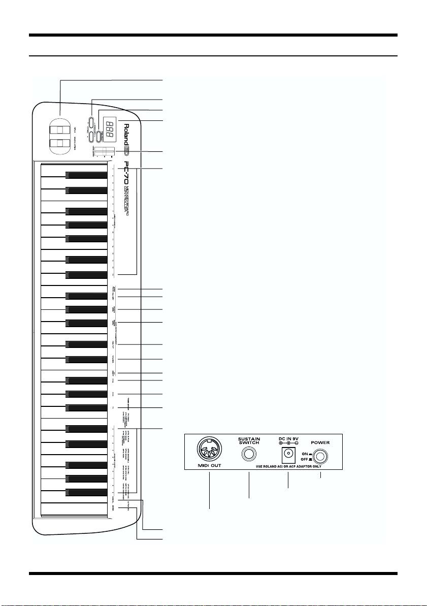
Panel Descriptions
fig.Panel.e
[1] PITCH / MODULATION Wheels
[2] OCTAVE UP / DOWN / STANDARD Buttons
[3] MIDI / SELECT Button
[4] DISPLAY(LED)
[5] DATA ENTRY Slider
[6] MIDI CHANNELS (1 to 16)
[7] AFTERTOUCH
[8] VELOCITY
[9] CHORUS LEVEL
[10] REVERB LEVEL
[11] PANPOT
[12] VOLUME
[13] CC SELECT(Select Control Change)
[14] CC32
[15] CC00
[16] PC(Program Change)
[17] NUMERIC ENTRY Section (0 to 9)
[22] AC Adapter Jack
[21] SUSTAIN SWITCH Jack
[20] MIDI OUT Connector
[18] CANCEL
[19] ENTER
[23] POWER Switch
9
Page 10

Power
How to Connect the AC Adaptor
The PC-70 can be powered by an AC adaptor.
Be sure to use only the attached AC adaptor. Using any other adaptor may cause
malfunction or electric shock.
1.
Check that the unit is OFF.
2.
Connect the AC adaptor to the AC Adaptor jack, then connect the plug to a power
outlet.
* To prevent malfunction and/or damage to speakers or other devices, always turn down the volume,
and turn off the power on all devices before making any connections.
* If the unit is to remain unused for an extended period of time, unplug the AC adaptor.
Setting Up the PC-70
The PC-70 is a MIDI controller. Although it contains no sound-generating circuitry of its
own, it can effectively control external units (sound module, computer, etc.) by transmitting
a wide variety of MIDI messages.
To ensure maximum benefit from your system, be sure to read this manual and the manuals
for all external equipment.
■
Sound Module Setup
Connect between the MIDI OUT connector on the PC-70 and the MIDI IN connector on the
sound module.
* To prevent malfunction and/or damage to speakers or other devices, always turn down the volume,
and turn off the power on all devices before making any connections.
fig.PC70-SC.e
10
MIDI IN
MIDI OUT
Sound Module
PC-70
OUTPUT
jacks
LINE IN jacks,
AUX jacks,
or TAPE IN jacks
Monitor speakers
(self-powered)
INPUT jacks
Stereo set, etc.
Page 11

■
Desk Top Music Setup
* When connecting your computer with a sound module, use only a cable which is designed for the
model of computer you are using and its particular kind of connector.
* If the sound module has a COMPUTER switch, make sure it is set to the appropriate position. The
correct position will vary depending on the type of computer, the way you are connecting with it, and
the requirements of the software you are using.
Computer Connected Using the Serial Connector on the Sound
Module
fig.PC70-Serial.e
RS-232C Connector
Computer Cable
Computer
Connector
Computer Switch
(Select one that is sutable for your computer.)
GS Sound Module
MIDI IN
Computer
MIDI OUT
PC-70
Computer Connected Using the MIDI IN Connector on the Sound
Module
fig.PC70-MPU.e
Computer Switch (MIDI)
GS Sound Module
MIDI IN
MIDI OUT
Computer
MIDI IN
PC-70
MIDI OUT
11
Page 12

Powering Up
* Once the connections have been completed (p. 10), turn on power to your various devices in the order
specified. By turning on devices in the wrong order, you risk causing malfunction and/or damage to
speakers and other devices.
Power to the various devices should be turned on in the appropriate order. First, turn on the
units from which MIDI messages will originate (computer, PC-70). Next, turn on the sound
module, then the audio reproduction equipment. This unit’s
its rear panel.
Power off your system in the reverse order.
* This unit is equipped with a protection circuit. A brief interval (a few seconds) after power up is
required before the unit will operate normally.
power switch [23]
is located on
Setting the MIDI Channel (MIDI Transmit Channel)
To control the sound module, set the MIDI channel the PC-70 will use to transmit on to the
same channel the module is using to receive on. If the sound module is multitimbral, set the
channel on the PC-70 so it matches the MIDI channel of the Part in the module that you wish
to control.
fig.MidiCh.e
MIDI Channel
12
[Procedure]
1.
Press
MIDI/SELECT [3]
2.
Select the MIDI channel by pressing one of the 16 keys in the
[6]
.
3.
Press
MIDI/SELECT [3]
(LED will show “SEL”).
again to confirm your selection.
MIDI channel section
Page 13

Selecting Sounds on a GS Sound Module (Sending Program Change/Bank Select Messages)
Program Change/Bank Select messages are used for changing Tones for an ordinary
instrument Part, and for changing Drum Sets for the Drum Part (GS: ch. 10).
Changing Sounds in a GS Sound Module
To change Tones in a GS module, you need to send the Bank Select message (consists of the
values for Controller Numbers [CC] 00 and 32) together with the Program Number.
The value of Controller Number 00 (MSB) and that of Controller Number 32 (LSB) work
together as a pair to specify a Bank. The Program Number that comes immediately after
completes the switch to the desired sound.
On the PC-70, these three messages are always sent as one set:
• Value of Controller Number 00 (MSB)
• Value of Controller Number 32 (LSB)
• Program Number xx
* You can conveniently refer to the GS/GM sound group list printed on the upper-right part of the
PC-70’s panel when specifying a Program Number.
[Procedure]
1.
Set the MIDI transmit channel to match that of the desired Part (in the sound module).
2.
Press
MIDI/SELECT [3]
3.
Press the
4.
Select the value of Controller Number 00 by pressing keys in the
section [17]
5.
Press
6.
Press the
7.
Select the value of Controller Number 32 by pressing keys in the
section [17]
8.
Press
9.
Press the
10.
Select the Program Number by pressing keys in the
11.
Press
12.
Press
G#4 black key (CC 00) [15]
.
ENTER [19]
F#4 black key (CC 32) [14]
.
ENTER [19]
A#4 black key (Program Change [PC]) [16]
ENTER [19]
MIDI/SELECT [3]
(LED will show “SEL”).
.
NUMERIC ENTRY
.
.
NUMERIC ENTRY
.
.
NUMERIC ENTRY section [17]
.
again to confirm your selection.
.
13
Page 14

[Example]
How to select the sound of Variation No. 8, Instrument No. 3 (Piano 3w) on the SC8850:
1. Set the MIDI transmit channel to match that of the desired Part in the module.
2. Press MIDI/SELECT [3] (LED will show “SEL”).
3. Press the G#4 black key (CC 00) [15].
4. Press the “8” key in the NUMERIC ENTRY section [17].
5. Press ENTER [19].
6. Press the F#4 black key (CC 32) [14].
7. Press the “4” key in the NUMERIC ENTRY section [17].
8. Press ENTER [19].
9. Press the A#4 black key (PC) [16].
10. Press the “3” key in the NUMERIC ENTRY section [17].
11. Press ENTER [19].
12. Press MIDI/SELECT [3] again to confirm your selection.
Changing Drum Sets in a GS Sound Module
The Drum Part (ch. 10) of a GS module does not respond to Bank Select messages. However,
if you try to send only a Program Change message from the PC-70, a Bank Select message
will end up being transmitted along with it anyway because the data for the last sound
specified will have been retained in memory. For this reason, you should always send a
value of 0 for Controller Numbers 00 and 32 first, then send the Program Number in order to
make sure you obtain the Drum Set you need.
[Procedure]
1.
Set the MIDI transmit channel to 10.
2.
Press
MIDI/SELECT [3]
3.
Press the
4.
Press the “0” key in the
5.
Press
6.
Press the
7.
Press the “0” key in the
8.
Press
9.
Press the
10.
Select the Program Number by pressing keys in the
11.
Press
12.
Press
G#4 black key (CC 00) [15]
ENTER [19]
F#4 black key (CC 32) [14]
ENTER [19]
A#4 black key (PC) [16]
ENTER [19]
MIDI/SELECT [3]
(LED will show “SEL”).
.
NUMERIC ENTRY section [17]
.
.
NUMERIC ENTRY section [17]
.
.
.
again to confirm your selection.
.
.
NUMERIC ENTRY section [17]
.
14
Page 15

[Example]
How to select the PC #49 Drum set (ORCHESTRA Set) on the SC-8850:
1. Set the MIDI transmit channel to 10.
2. Press MIDI/SELECT [3] (LED will show “SEL”).
3. Press the G#4 black key (CC 00) [15].
4. Press the “0” key in the NUMERIC ENTRY section [17].
5. Press ENTER [19].
6. Press the F#4 black key (CC 32) [14].
7. Press the “0” key in the NUMERIC ENTRY section [17].
8. Press ENTER [19].
9. Press the A#4 black key (PC) [16].
10. Press the “4” key and then “9” in the NUMERIC ENTRY section [17].
11. Press ENTER [19].
12. Press MIDI/SELECT [3] again to confirm your selection.
Features Useful When Playing
Applying Pitch Changes to Notes (Pitch Bend)
Move the BENDER wheel [1] (up or down) to transmit Pitch Bend messages, and apply
subtle pitch changes to notes.
* The Pitch Bend range varies depending on how it is set on the sound module.
Modifying the Sound of Notes: Modulation (CC 01)
Moving the MODULATION wheel [1] (up or down) will transmit Modulation messages,
changing the sound in real time (usually by adding a vibrato effect).
* The change obtained with this message will vary depending on the settings for your sound module (the
section which handles modulation), or the Tone selected.
Adding a Sustain Effect to Notes: Hold 1 (CC 64)
After connecting a pedal switch, you can depress it while playing to send the Hold 1 message
(CC 64), causing notes that were playing to be sustained. If an electric organ or other
normally sustained type sound was being sounded, the notes will continue for as long as you
have the pedal down. The pedal switch should be connected to the SUSTAIN SWITCH jack
[21] on the rear of the unit.
Depressing the pedal will transmit an ON value (127), while releasing it will transmit an OFF
value (0).
* The Hold 1 (CC 64) function can be assigned to the DATA ENTRY slider [5], allowing you to obtain
the damper effect by moving the slider.
15
Page 16

Changing Octaves
Using the OCTAVE [2] buttons (UP, DOWN), the soundable range of the keyboard can be
shifted up or down by one octave, making it possible to access all of the notes from C0 to C8.
Ex.) Shift the Sound Range Up One Octave: OCTAVE UP
Press UP in the OCTAVE [2] once; the keyboard will now offer notes within a range an
octave higher.
fig.Octave1
C3 (48) C7 (96)
Ex.) Shift the Sound Range Down One Octave: OCTAVE DOWN
Press DOWN in the OCTAVE [2] once; the keyboard will now offer notes within a range an
octave lower.
fig.Octave2
C1 (24) C5 (72)
Return to the Normal Sound Range: STANDARD
Press UP and DOWN simultaneously.
fig.Octave3
C2 (36) C6 (84)
16
Page 17

Controlling a Sound Module with the DATA ENTRY Slider
The following functions can be assigned to the DATA ENTRY slider:
Function nameDescription
Channel Aftertouch Alters notes currently being played
VelocityChanges dynamics
Reverb Send Level (CC 91)Sets the depth of Reverb
Chorus Send Level (CC 93)Sets the depth of Chorus
Volume (CC 07)Sets the volume level of the Part
Panpot (CC 10)Sets sound position (localization in the stereo sound field)
CC 00 to 127Depends on the selected Controller Number
* Since a slider control accesses digital information, it might not produce any noticeable change in the
value if moved by only a small amount. If this happens, move the slider up and down once, then set the
value.
Altering the Timbre of Notes Currently Being Played (Channel
Aftertouch)
The keyboard on the PC-70 cannot transmit Channel Aftertouch messages. However, such
messages can be transmitted by assigning the Channel Aftertouch function to the DATA
ENTRY slider on the PC-70.
Channel Aftertouch is a function that lets you alter notes (that have already been played) by
applying additional pressure on the keys. The PC-70 can create this Aftertouch effect—
simply move the DATA ENTRY slider after Aftertouch has been assigned to it.
fig.aftertouch.e
Aftertouch
[Procedure]
1. Set the MIDI transmit channel to match that of the desired Part.
2. Press MIDI/SELECT [3] (LED will show “SEL”).
3. Press the F3 white key (AFTER TOUCH) [7].
4. Press MIDI/SELECT [3] again to confirm your selection. Now, when you move the
DATA ENTRY slider, Channel Aftertouch messages (with a value reflecting the
slider’s position) will be transmitted.
* A GS sound module will not respond to Aftertouch messages while it remains set at its factory
defaults. For details, refer to the owner’s manual for the sound module you are using. Computer users
should consult the owner’s manual for their software, since it may be possible to select a response for
Channel Aftertouch within the software.
17
Page 18

Changing the Velocity Sensitivity: Velocity
Whenever a key is pressed on the instrument, the value for velocity will be transmitted along
with the note information. The following setting allows you to choose the sensitivity of the
response to velocity (range of possible change).
fig.VeloCurv.e
Slider position: minimum
Slider position: center
Slider position: maximum
fig.velocity.e
[Procedure]
Velocity value
Strength of key touch
Velocity value
Strength of key touch
Velocity value
Strength of key touch
Velocity
1. Set the MIDI channel to match that of the Part (sound module) to be controlled.
2. Press MIDI/SELECT [3] (LED will show “SEL”).
3. Press the F#3 black key (VELOCITY) [8].
4. Press MIDI/SELECT [3] again to confirm your selection. Move the DATA ENTRY
slider to select the minimum value, thus setting the desired range for velocity. With
the slider at its maximum, velocity values within the entire 1–127 range can be
generated.
18
Page 19

Changing the Chorus Depth: Chorus Send Level (CC 93)
This function allows you to set the Chorus depth for each Part.
fig.chorus.e
Chorus Depth
[Procedure]
1. Set the MIDI transmit channel to match that of the desired Part.
2. Press MIDI/SELECT [3] (LED will show “SEL”).
3. Press the A#3 black key (CHORUS LEVEL) [9].
4. Press MIDI/SELECT [3] again to confirm your selection. Now you can use the DATA
ENTRY slider to select the value transmitted for the Chorus Send Level (Effect 3
Depth).
* When a sound module other than a GS module is being used, the relevant parameter may not correctly
respond to CC 93 messages.
Changing the Reverb Depth: Reverb Send Level (CC 91)
This function allows you to set the Reverb depth for each Part.
fig.reverb.e
Reverb Depth
[Procedure]
1. Set the MIDI transmit channel to match that of the desired Part.
2. Press MIDI/SELECT [3] (LED will show “SEL”).
3. Press the G#3 black key (REVERB LEVEL) [10].
4. Press MIDI/SELECT [3] again to confirm your selection. Now you can use the DATA
ENTRY slider to select the value transmitted for the Reverb Send Level (Effect 1
Depth).
* When a sound module other than a GS or General MIDI module is being used, the relevant parameter
may not correctly respond to CC 91 messages.
19
Page 20

Setting the Sound Location: Panpot (CC 10)
When the module is connected so its sounds are produced in stereo, this parameter
determines the stereo placement (L/R) of the individual sounds produced. For the Drum
Part (ch. 10), it alters in a relative manner the overall Panpot setting for percussive
instruments (the overall orientation of the Drum Part on a GS module).
fig.pan.e
Pan
[Procedure]
1. Set the MIDI transmit channel to match that of the desired Part.
2. Press MIDI/SELECT [3] (LED will show “SEL”).
3. Press the C#4 black key (PANPOT) [11].
4. Press MIDI/SELECT [3] again to confirm your selection. Now you can use the DATA
ENTRY slider to set the value to be transmitted for the Panpot. With the slider at the
center, the sound will be oriented in the center. When pulled all the way forward, the
sound will be heard from the extreme left. When pushed completely back, the sound
will come from the right.
Changing the Volume: Volume (CC 07)
This function allows you to adjust the volume level for each Part.
fig.volume.e
20
Volume
[Procedure]
1. Set the MIDI transmit channel to match that of the desired Part.
2. Press MIDI/SELECT [3] (LED will show “SEL”).
3. Press the D#4 black key (VOLUME) [12].
4. Press MIDI/SELECT [3] again to confirm your selection. Now you can use the DATA
ENTRY slider to set the value that will be transmitted for the Volume.
Page 21

Assigning Other Controllers (CC 00 to 127) to the DATA ENTRY
Slider
By assigning a controller number to the DATA ENTRY slider, the slider can be used for
controlling a wide range of features on your sound module.
Any controller numbered from 0 to 95 (Continuous Controllers) can be assigned. Since the
PC-70 isn’t equipped with a display which allows you to monitor data when transmitting it,
it is not suited for operations which involve Registered and Non-Registered Parameter
Numbers.
Controllers 00 through 95 (Continuous Controllers)
Controller No. Control Function
0. Bank Select MSB
1. Modulation
2. Breath Controller
3. Undefined
4. Foot Controller
5. Portamento Time
6. Data Entry (Used with RPN/NRPN)
7. Main Volume
8. Balance
9. Undefined
10. Panpot
11. Expression Pedal
12. Effect Control 1
13. Effect Control 2
14–15 Undefined
16. General Purpose Controller 1
17. General Purpose Controller 2
18. General Purpose Controller 3
19. General Purpose Controller 4
20–31 Undefined
32. Bank Select LSB
33–63 LSB for controllers 1-31
64. Hold 1 (Damper)
65. Portamento
66. Sostenuto
67. Soft Pedal
68. Undefined
69. Hold 2 (Freeze)
70–79 Undefined
80. General Purpose Controller 5
81. General Purpose Controller 6
82. General Purpose Controller 7
83. General Purpose Controller 8
84–90 Undefined
91. Effect 1 (External Effect) Depth
(GS/General MIDI: Reverb Send Level)
92. Effect 2 (Tremolo) Depth
93. Effect 3 (Chorus) Depth (GS: Chorus Send Level)
94. Effect 4 (Celeste) Depth
95. Effect 5 (Phaser) Depth
21
Page 22

Controllers 96 and above (NRPN/RPN, Channel Mode Messages)
fig.controller.e
[Procedure]
Controller No. Control Function
96. Data Increment
97. Data Decrement
98. Non-Registered Parameter Number LSB
99. Non-Registered Parameter Number MSB
100. Registered Parameter Number LSB
101. Registered Parameter Number MSB
102–120 Undefined
121–127 Reserved for Channel Mode Messages
Select CC Numeric Key Pad Enter
1. Set the MIDI transmit channel to match that of the desired Part.
2. Press MIDI/SELECT [3] (LED will show “SEL”).
3. Press the F4 white key (CC SELECT) [13].
4. Select the Controller Number by pressing keys in the NUMERIC ENTRY section [17].
5. Press ENTER [19].
6. Press MIDI/SELECT [3] again to confirm your selection. Now you can use the DATA
ENTRY slider to transmit the value of the specified Controller Number.
22
Page 23

Troubleshooting
Q: The unit cannot be switched on; or it doesn’t work at all.
A: Check if you are using the attached AC adaptor. Use only the attached adaptor—using
any other adaptor may result in damage, malfunction or electric shock.
Q: The sound module does not respond to the movement of the DATA ENTRY slider.
A: Check if the correct function is assigned to the DATA ENTRY slider. Also, note that the
module will sometimes not respond if the slider is moved only slightly. If you are
unsure, pull the slider all the way down first and then set it to the desired position.
Q: The sound you have requested cannot be selected.
A: Some GS modules, such as those in the Sound Canvas series, have a switch which allows
you to turn on or off the reception of Program Change messages and/or Bank Select
messages. Be sure this switch is turned ON.
A: Could the sound module have received a GM System On message (the message that
orders a module to function as a General MIDI sound module) before you sent Bank
Select messages? Since Bank Selects are not recognized in the General MIDI System Level
1 specifications, the module will ignore them if it is currently behaving as a General
MIDI device. To correct this situation, send a GS Reset message (which retrieves the GS
default settings), or simply switch the module off, then on again.
* The PC-70 cannot transmit GS Reset messages.
A: When specifying the change in sound, did you supply the complete set of values (values
for CC 00/CC 32 and Program Number)? When a change in sound is made using the PC70, the complete set of three values (value for CC 00 and CC 32, then the Program
number) is transmitted, even if only the Program Number has been specified. Note also
that the values for a sound selection remain stored in memory until the next sound has
been successfully selected. So, if even one out of the complete set of three values is
mistakenly not supplied, part of the previous values could be sent along with the newly
specified ones. As a result, you might not obtain the sound you hoped for.
A: Does your computer music application use Program Numbers 0 to 127 for sound
selection? Since the PC-70 uses numbers 1 to 128, you may need to add one to the
number being selected to obtain the correct sound.
Q: The GS module does not respond to Aftertouch messages.
A: A GS sound module will not respond to Aftertouch messages when it’s in its default
mode. Therefore, you need to set the Aftertouch parameters using Exclusive messages.
(Refer to the MIDI Implementation for the sound module in question.) If using a
computer-based system, you may be able to easily make the required settings using the
software.
23
Page 24

fig.MIDI-Imp.e
Version : 1.00
Remarks
Date : May. 12, 2000
X
X
XXX
Transmitted Recognized
MIDI Implementation Chart
MIDI Keyboard controller
Model PC-70
1
1–16
Function...
Default
Changed
Basic
Channel
Mode 3
X
Default
Messages
Mode
X
0–127
**************
Altered
Note
X
X
**************
True Voice
Number :
X
O
X
Note On
Note Off
Velocity
X
X
X
O
Key's
Channel's
After
Touch
X
X
* 1
O
O
0–127
Pitch Bend
Control
Change
24
Page 25

fig.MIDI-Imp.e
X : No
O : Yes
X
X
X
XXX
X
X
XXX
X
1–128
X
**************
: True Number
Program
Change
System Exclusive
XXX
: Song Position
: Song Select
System
Common
X
: Tune Request
: Clock
System
X
XXXXO
: Commands
Real Time
Reset All Controller
: All Sound Off
:
: Local On/Off
Aux
X
* 1 Messages are tx over particular conditions.
: All Notes Off
: Active Sensing
: System Reset
Messages
Notes
Mode 2 : OMNI ON, MONO
Mode 4 : OMNI OFF, MONO
Mode 1 : OMNI ON, POLY
Mode 3 : OMNI OFF, POLY
25
Page 26

Specifications
Keyboard
49 keys (velocity sensitive)
MIDI Control
MIDI Channels (1 to 16)
Octave Shift (Up, Down, Standard) (Note Numbers 0 to 127)
Bender/Modulation Wheel (Modulation On/Off)
Data Entry Slider
Controller Numbers 00/32 (GS Variation selection)
Channel Aftertouch
Velocity
Chorus Send Level
Reverb Send Level
Panpot
Volume
Others (Controller Numbers 0 to 127)
Display
7 segments, 3 characters (LED)
Rear Panel
Power Switch, Sustain Switch jack, AC Adaptor jack, and MIDI OUT connector
Power Supply
DC 9 V: AC Adaptor (ACP or ACI series)
Current Draw
160 mA
Dimensions
844 (W) x 210 (D) x 73 (H) mm
33-1/4 (W) x 8-5/16 (D) x 2-7/8 (H) inches
Weight
2.7 kg/6 lbs
Accessories
Owner's Manual, MIDI Cable, Pedal Switch, AC Adaptor
* In the interest of product improvement, the specifications and/or appearance of this unit are subject to
change without prior notice.
26
Page 27

Information
When you need repair service, call your nearest Roland/EDIROL Service Center or authorized Roland/EDIROL distributor
in your country as shown below.
AFRICA
AFRICA
EGYPT
Al Fanny Trading Office
P.O. Box 2904,
El Horrieh Heliopolos, Cairo,
EGYPT
TEL: (02) 4185531
REUNION
Maison FO - YAM Marcel
25 Rue Jules MermanZL
Chaudron - BP79 97491
Ste Clotilde REUNION
TEL: 28 29 16
SOUTH AFRICA
That Other Music Shop
(PTY) Ltd.
11 Melle Street (Cnr Melle and
Juta Street)
Braamfontein 2001
Republic of SOUTH AFRICA
TEL: (011) 403 4105
Paul Bothner (PTY) Ltd.
17 Werdmuller Centre Claremont
7700
Republic of SOUTH AFRICA
P.O. Box 23032
Claremont, Cape Town
SOUTH AFRICA, 7735
TEL: (021) 64 4030
ASIA
CHINA
Beijing Xinghai Musical
Instruments Co., Ltd.
6 Huangmuchang Chao Yang
District, Beijing, CHINA
TEL: (010) 6774 7491
HONG KONG
Tom Lee Music Co., Ltd.
Service Division
22-32 Pun Shan Street, Tsuen
Wan, New Territories,
HONG KONG
TEL: 2415 0911
INDIA
Rivera Digitec (India) Pvt. Ltd.
409, Nirman Kendra Mahalaxmi
Flats Compound Off. Dr. Edwin
Moses Road, Mumbai-400011,
INDIA
TEL: (022) 498 3079
INDONESIA
PT Citra IntiRama
J1. Cideng Timur No. 15J-150
Jakarta Pusat
INDONESIA
TEL: (021) 6324170
KOREA
Cosmos Corporation
Service Station
261 2nd Floor Nak-Won Arcade
Jong-Ro ku, Seoul, KOREA
TEL: (02) 742 8844
MALAYSIA
Bentley Music SDN BHD
140 & 142, Jalan Bukit Bintang
55100 Kuala Lumpur,MALAYSIA
TEL: (03) 2443333
PHILIPPINES
G.A. Yupangco & Co. Inc.
339 Gil J. Puyat Avenue
Makati, Metro Manila 1200,
PHILIPPINES
TEL: (02) 899 9801
SINGAPORE
CRISTOFORI MUSIC PTE
LTD
Blk 3014, Bedok Industrial Park E,
#02-2148, SINGAPORE 489980
TEL: 243 9555
TAIWAN
ROLAND TAIWAN
ENTERPRISE CO., LTD.
Room 5, 9fl. No. 112 Chung Shan
N.Road Sec.2, Taipei, TAIWAN,
R.O.C.
TEL: (02) 2561 3339
THAILAND
Theera Music Co. , Ltd.
330 Verng NakornKasem, Soi 2,
Bangkok 10100, THAILAND
TEL: (02) 2248821
VIETNAM
Saigon Music
138 Tran Quang Khai St.,
District 1
Ho Chi Minh City
VIETNAM
TEL: (08) 844-4068
AUSTRALIA/
NEW ZEALAND
NEW ZEALAND
Roland Corporation (NZ) Ltd.
97 Mt. Eden Road, Mt. Eden,
Auckland 3, NEW ZEALAND
TEL: (09) 3098 715
CENTRAL/LATIN
AMERICA
ARGENTINA
Instrumentos Musicales S.A.
Florida 656 2nd Floor
Office Number 206A
Buenos Aires
ARGENTINA, CP1005
TEL: (54-11) 4- 393-6057
BRAZIL
Roland Brasil Ltda.
R. Coronel Octaviano da Silveira
203 05522-010
Sao Paulo BRAZIL
TEL: (011) 3743 9377
MEXICO
Casa Veerkamp, s.a. de c.v.
Av. Toluca No. 323 Col. Olivar de
los Padres 01780 Mexico D.F.
MEXICO
TEL: (525) 668 04 80
La Casa Wagner de
Guadalajara s.a. de c.v.
Av. Corona No. 202 S.J.
Guadalajara, Jalisco Mexico
C.P.44100 MEXICO
TEL: (3) 613 1414
PANAMA
Productos Superiores, S.A.
Calle Canfield-Albrook, Panama
REP. DE PANAMA
TEL: (507) 315-0101
URUGUAY
Todo Musica
Cuareim 1488, Montevideo,
URUGUAY
TEL: 5982-924-2335
VENEZUELA
Musicland Digital C.A.
Av. Francisco de Miranda,
Centro Parque de Cristal, Nivel
C2 Local 20 Caracas
VENEZUELA
TEL: (02) 285 9218
EUROPE
AUSTRIA
Roland Austria GES.M.B.H.
Siemensstrasse 4, P.O. Box 74,
A-6063 RUM, AUSTRIA
TEL: (0512) 26 44 260
BELGIUM/HOLLAND/
LUXEMBOURG
Roland Benelux N. V.
Houtstraat 3 B-2260 Oevel
(Westerlo) BELGIUM
TEL: (014) 575811
DENMARK
Roland Scandinavia A/S
Nordhavnsvej 7, Postbox 880
DK-2100 Copenhagen
DENMARK
TEL: (039)16 6200
FRANCE
Roland France SA
4, Rue Paul Henri SPAAK
Parc de l'Esplanade F 77 462 St.
Thibault Lagny Cedex FRANCE
TEL: 01 600 73 500
FINLAND
Roland Scandinavia As,
Filial Finland
Lauttasaarentie 54 B
Fin-00201 Helsinki, FINLAND
TEL: (9) 682 4020
GERMANY
Roland Elektronische
Musikinstrumente
Handelsgesellschaft mbH.
Oststrasse 96, 22844 Norderstedt,
GERMANY
TEL: (040) 52 60090
GREECE
STOLLAS S.A.
Music Sound Light
155, New National Road
26422 Patras, GREECE
TEL: 061-435400
HUNGARY
Intermusica Ltd.
Warehouse Area ‘DEPO’ Pf.83
H-2046 Torokbalint, HUNGARY
TEL: (23) 511011
IRELAND
Roland Ireland
Audio House, Belmont Court,
Donnybrook, Dublin 4.
Republic of IRELAND
TEL: (01) 2603501
ITALY
Roland Italy S. p. A.
Viale delle Industrie, 8
20020 Arese Milano, ITALY
TEL: (02) 937-78300
NORWAY
Roland Scandinavia Avd.
Kontor Norge
Lilleakerveien 2 Postboks 95
Lilleaker N-0216 Oslo
NORWAY
TEL: 273 0074
POLAND
P. P. H. Brzostowicz
UL. Gibraltarska 4.
PL-03664 Warszawa POLAND
TEL: (022) 679 44 19
PORTUGAL
Tecnologias Musica e Audio,
Roland Portugal, S.A.
RUA DE SANTA CARARINA
131 - 4000 Porto -PORTUGAL
TEL: (02) 208 44 56
ROMANIA
FBS LINES
Plata Libertatii 1.
RO-4200 Cheorgheni
TEL: (066) 164-609
RUSSIA
Slami Music Company
Sadojava-Triumfalnaja st., 16
103006 Moscow, RUSSIA
TEL: 095 209 2193
SPAIN
Roland Electronics
de España, S. A.
Calle Bolivia 239 08020 Barcelona,
SPAIN
TEL: (93) 308 1000
SWEDEN
Roland Scandinavia A/S
SWEDISH SALES OFFICE
Danvik Center 28, 2 tr.
S-131 30 Nacka SWEDEN
TEL: (08) 702 0020
SWITZERLAND
Roland (Switzerland) AG
Musitronic AG
Gerberstrasse 5, CH-4410 Liestal,
SWITZERLAND
TEL: (061) 921 1615
UKRAINE
TIC-TAC
Mira Str. 19/108
P.O. Box 180
295400 Munkachevo, UKRAINE
TEL: (03131) 414-40
UNITED KINGDOM
Roland (U.K.) Ltd.
Atlantic Close, Swansea
Enterprise Park SWANSEA
SA7 9FJ,
UNITED KINGDOM
TEL: (01792) 700139
MIDDLE EAST
BAHRAIN
Moon Stores
Bab Al Bahrain Road,
P.O. Box 20077
State of BAHRAIN
TEL: 211 005
CYPRUS
Radex Sound Equipment Ltd.
17 Diagorou St., P.O. Box 2046,
Nicosia CYPRUS
TEL: (02) 453 426
ISRAEL
Halilit P. Greenspoon &
Sons Ltd.
8 Retzif Fa'aliya Hashnya St.
Tel-Aviv-Yaho ISRAEL
TEL: (03) 6823666
JORDAN
AMMAN Trading Agency
Prince Mohammed St. P.O. Box
825 Amman 11118 JORDAN
TEL: (06) 4641200
KUWAIT
Easa Husain Al-Yousifi
P.O. Box 126 Safat 13002
KUWAIT
TEL: 5719499
LEBANON
A. Chahine & Fils
P.O. Box 16-5857 Gergi Zeidan St.
Chahine Building, Achrafieh
Beirut, LEBANON
TEL: (01) 335799
OMAN
OHI Electronics & Trading
Co. LLC
P.O. Box 889 Muscat
Sultanate of OMAN
TEL: 959085
QATAR
Badie Studio & Stores
P.O. Box 62,
DOHA QATAR
TEL: 423554
SAUDI ARABIA
aDawliah Universal
Electronics APL
P.O. Box 2154 ALKHOBAR 31952,
SAUDI ARABIA
TEL: (03) 898 2081
SYRIA
Technical Light & Sound
Center
Khaled Ibn Al Walid St.
P.O. Box 13520
Damascus - SYRIA
TEL: (011) 2235 384
TURKEY
Barkat Muzik aletleri ithalat
ve ihracat Ltd Sti
Siraselviler cad.Guney is hani 8486/6, Taksim. Istanbul. TURKEY
TEL: (0212) 2499324
U.A.E.
Zak Electronics & Musical
Instruments Co.
Zabeel Road, Al Sherooq Bldg.,
No. 14, Grand Floor DUBAI
U.A.E.
P.O. Box 8050 DUBAI, U.A.E.
TEL: (04) 3360715
AUSTRALIA
EDIROL Australia Pty. Ltd.
72 Central Avenue
Oak Flats NSW 2529
AUSTRALIA
TEL: (02) 4258 9040
U. S. A. / CANADA
EDIROL Corporation North
America
808 Harrison Ave., Suite 2010
P.O. Box 4919
Blaine, WA 98231
U. S. A.
TEL: (360) 332-4211
EUROPE
EDIROL (Europe) Ltd.
Studio 3.4 114 Power Road
London W4 5PY
U. K.
TEL: +44 (0) 20 8747 5949
As of May 12, 2000 (EDIROL)
Page 28

02343089 ’00-6-C4-11SK
 Loading...