

Page 1

PC-300
MIDI Keyboard Controller
Owner’s Manual
Bedienungsanleitung
Mode d’emploi
Handleiding
Manuale d’uso
Manual del usuario
Page 2

Page 3

Thank you, and congratulations on your choice of the Roland PC-300.
The PC-300 is an easy-to-operate, dedicated keyboard controller for GS compatible sound
modules fitted with a USB connector. This connection offers the advantage that the PC-300
can also be powered via USB, while ensuring compatibility with the new connection standard for both IBM PC compatible and Macintosh® computers.
Please take the time to read through this Owner’s Manual. That way you can feel assured
that you understand every feature the unit offers, and will enjoy many years of trouble-free
operation.
Owner’s Manual
1
Copyright © 2000 Roland Europe Spa
All rights reserved. No part of this publication may be reproduced in any form without the
written permission of Roland Europe Spa - Acquaviva Picena (AP) - Italy.
ENGLISH
Page 4

1. Contents
2
PC-300
2. About the PC-300 . . . . . . . . . . . . . . . . . . . . . . . . . . . . . . . . . . . . . . . . . . . . . . . . . .3
What is the GS Format (g)? . . . . . . . . . . . . . . . . . . . . . . . . . . . . . . . . . . . . . . . . . . . . .3
3. Main features of the PC-300 . . . . . . . . . . . . . . . . . . . . . . . . . . . . . . . . . . . . . . . . . .4
4. Important notes . . . . . . . . . . . . . . . . . . . . . . . . . . . . . . . . . . . . . . . . . . . . . . . . . . . .5
5. Panel descriptions . . . . . . . . . . . . . . . . . . . . . . . . . . . . . . . . . . . . . . . . . . . . . . . . . .6
6. Connecting & setting up the PC-300 . . . . . . . . . . . . . . . . . . . . . . . . . . . . . . . . . . . .7
Power supply . . . . . . . . . . . . . . . . . . . . . . . . . . . . . . . . . . . . . . . . . . . . . . . . . . . . . . . . . .7
Setting up the PC-300 . . . . . . . . . . . . . . . . . . . . . . . . . . . . . . . . . . . . . . . . . . . . . . . . . . .8
Powering up . . . . . . . . . . . . . . . . . . . . . . . . . . . . . . . . . . . . . . . . . . . . . . . . . . . . . . . . . .10
Setting the MIDI transmit channel . . . . . . . . . . . . . . . . . . . . . . . . . . . . . . . . . . . . . . . .11
Selecting sounds . . . . . . . . . . . . . . . . . . . . . . . . . . . . . . . . . . . . . . . . . . . . . . . . . . . . . .11
Selecting Drum Sets on a GS sound module . . . . . . . . . . . . . . . . . . . . . . . . . . . . . . . .12
7. Various useful functions . . . . . . . . . . . . . . . . . . . . . . . . . . . . . . . . . . . . . . . . . . . .13
Temporarily changing the pitch of a note (Pitch Bend) . . . . . . . . . . . . . . . . . . . . . . .13
Adding vibrato (Modulation) . . . . . . . . . . . . . . . . . . . . . . . . . . . . . . . . . . . . . . . . . . . .13
Holding the notes your play (Sustain) . . . . . . . . . . . . . . . . . . . . . . . . . . . . . . . . . . . . .13
8. Changing octaves . . . . . . . . . . . . . . . . . . . . . . . . . . . . . . . . . . . . . . . . . . . . . . . . .14
9. Controlling a sound module with the DATA ENTRY slider . . . . . . . . . . . . . . . . . .15
Altering the timbre (Channel Aftertouch) . . . . . . . . . . . . . . . . . . . . . . . . . . . . . . . . . .15
Changing the velocity sensitivity . . . . . . . . . . . . . . . . . . . . . . . . . . . . . . . . . . . . . . . . .16
Reverb level . . . . . . . . . . . . . . . . . . . . . . . . . . . . . . . . . . . . . . . . . . . . . . . . . . . . . . . . . .16
Chorus level . . . . . . . . . . . . . . . . . . . . . . . . . . . . . . . . . . . . . . . . . . . . . . . . . . . . . . . . . .16
Setting the sound location: Panpot . . . . . . . . . . . . . . . . . . . . . . . . . . . . . . . . . . . . . . . .17
Changing the volume . . . . . . . . . . . . . . . . . . . . . . . . . . . . . . . . . . . . . . . . . . . . . . . . . .17
If notes are stuck: Panic . . . . . . . . . . . . . . . . . . . . . . . . . . . . . . . . . . . . . . . . . . . . . . . . .17
Assigning other control changes to the DATA ENTRY slider . . . . . . . . . . . . . . . . . . .18
10. Troubleshooting . . . . . . . . . . . . . . . . . . . . . . . . . . . . . . . . . . . . . . . . . . . . . . . . . .19
11. Specifications . . . . . . . . . . . . . . . . . . . . . . . . . . . . . . . . . . . . . . . . . . . . . . . . . . . .20
Page 5

2. About the PC-300
3
Owner’s Manual
The Roland PC-300 is a MIDI keyboard
controller designed to provide for the convenient transmission of Program Change
and Bank Select messages, as well as a variety of other MIDI messages (such as
Reverb and Chorus information) to an
external sound module. It contains no
internal sound source. It is particularly
suited for controlling sound modules that
comply with the GS Format. (Called simply “GS sound modules” in the following.)
What is the GS Format (g)?
The GS Format is a standardized set of
specifications for Roland’s sound sources
which defines the manner in which multitimbral sound generating units will
respond to MIDI messages. All devices
compatible with the GS Format bear the
GS logo. Every module or device with the
GS logo will respond in the same way to
the MIDI messages sent from the PC-300.
Note: All Roland GS sound modules also fully
support Level 1 of the General MIDI System
(
m).
In 1990, the MIDI standard incorporated
the Program Change/Bank Select message
cluster (selection of sounds using both
program numbers and control change
numbers CC00 and CC32). The GS
Format accommodates this form of sound
selection, which allows for a much larger
number of sounds to be selected.
About the sounds contained in a GS
sound module
A GS sound module contains 128 basic
sounds (“Capital Tones”) and a number of
Variation Tones. The mapping for the
Capital Tones is compatible with Level 1 of
the General MIDI System. Capital Tones
are stored in bank 0, while the Variations
are stored in banks 1 through 127. The
number of available Variation Tones
depends on the sound module you are
using. Please see the manual of the sound
module(s) your are using to find out how
may sounds there are and how to access
them.
About the Drum Sets Provided by a GS
Sound Module
The MIDI channel used for the Rhythm
Set/Drum Set/Drum Part of a GM/GS
module (MIDI channel 10) provides for
the use of several Variation Sets in addition to the basic Drum Set (Standard Set:
program change number PC01). Though
most Drum Sets can be selected using program change messages, the module your
are using may also contain a number of
Variation Sets. Please see its manual for
details.
Note: If a Variation Tone or Variation Drum
Set you have requested is not available in the
GS module you are using, the module may not
sound at all, or use a Drum Set with different
sounds.
ENGLISH
Page 6

3. Main features of the PC-300
4
PC-300
USB connector
The PC-300 comes with a USB connector
that allows you to connect it to an IBM
compatible PC or a Macintosh® computer
fitted with USB connectors (iMac®, G4,
etc.). This connector allows for high-speed
data transfer and supplying power to the
connected devices.
USB drivers
The PC-300 is supplied with various USB
drivers for both IBM compatible and
Macintosh® computers. See the included
booklet for details.
Superb playability and expressiveness
This standard 49-key keyboard velocity
sensitive and therefore allows you to
express even the finest nuances. In addition, an Octave Shift feature allows you to
conveniently shift the soundable range up
or down. Moreover, the PC-300 is
equipped with a Pitch Bend/Modulation
lever, and provides a SUSTAIN SWITCH
jack for connecting a Sustain/Hold pedal.
Complete range of control
features
Since the keyboard provides for sound
selection that uses combinations of
Program Change and Bank Select messages (CC 00 and CC 32), you can also
select any of the Variation Tones that may
be available on a GS sound module.
In addition, a variety of continuous controllers (Control Changes) can be assigned
to the DATA ENTRY slider. The slider can
then be used for controlling the desired
parameter (Reverb or Chorus Depth, for
example) of a GS sound module.
Makes Desk Top Music (DTM)
more enjoyable
The PC-300 is very compact, so it requires
only a minimal amount of desktop space.
The PC-300 is sure to become an invaluable part of any DTM setup, since it can
be used for real-time or step recording, as
well as for practice while listening to
“minus-one” playback.
Page 7

4. Important notes
5
Owner’s Manual
Be sure to only use the supplied Roland
ACA series adapter. Use of any other AC
adapter could result in damage, malfunction or electric shock.
Power supply
• Before connecting this unit to other devices,
turn off the power to all units; this will help
prevent damage or malfunction.
• Be sure to set the POWER switch on the rear
panel according to the power source you are
using (adapter or USB).
• Do not use this unit on the same power circuit
with any device that will generate line noise,
such as an electric motor or variable lighting
system.
• The power requirement for this unit is indicated
next to the DC IN connector (rear panel) as
well as on the adapter’s nameplate. Be sure that
the outlet you choose meets this requirement.
• Avoid damaging the adapter’s power cord: do
not step on it, place heavy objects on it, etc.
• When disconnecting the AC adapter from the
power outlet, grasp the plug itself; never pull on
the cord.
• If the unit is to remain unused for an extended
period of time, unplug the adapter.
Placement
• Do not subject the unit to temperature
extremes (e.g., direct sunlight in an enclosed
vehicle). Avoid using or storing the unit in
dusty or humid areas, or areas that are subject
to high levels of vibration.
• Using the unit near power amplifiers (or other
equipment containing large power transformers) may induce hum.
• This device may interfere with radio and television reception. Do not use it in the vicinity of
such receivers.
Maintenance
• For everyday cleaning wipe the unit with a soft,
dry cloth or one that has been slightly dampened with water. To remove stubborn dirt, use a
mild, non-abrasive detergent. Afterwards, be
sure to wipe the unit thoroughly with a soft, dry
cloth.
• Never use benzene, thinners, alcohol or solvents
of any kind, to avoid the possibility of discoloration and/or deformation.
Additional precautions
• Protect the unit from strong impact.
• Do not allow objects or liquids of any kind to
penetrate the unit. In the event of such an
occurrence, discontinue use immediately.
Contact qualified service personnel as soon as
possible.
• A small amount of heat will radiate from the
unit during normal operation.
• Before using the unit in a foreign country, consult with qualified service personnel.
• Should the unit malfunction, or if you suspect
there is a problem, discontinue use immediately.
Contact qualified service personnel as soon as
possible.
• To avoid the risk of electric shock, do not open
the unit.
ENGLISH
Page 8

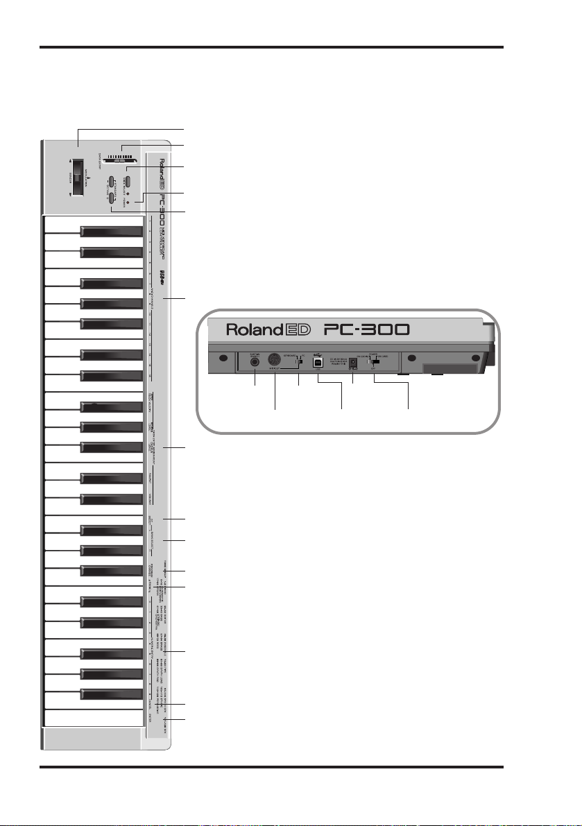
5. Panel descriptions
6
PC-300
[1] BENDER/MODULATION lever
[2] DATA ENTRY slider
[3] MIDI SELECT button & indicator
[5] OCTAVE [–]/[+] buttons
[6] MIDI CHANNELS keys
[7] DATA ENTRY ASSIGNMENT keys
SUSTAIN SWITCH
connector
MIDI OUT
connector
[8] CC SELECT key
[9] BANK SELECT [L] & [H] keys
[10] PROGRAM CHANGE key
[11] PANIC keys
[12] NUMERIC ENTRY keys
[13] CANCEL key
[14] ENTER key
KEYBOARD/PC
select switch
USB connector
DC IN
connector
POWER DC IN/USB
switch
[4] POWER indicator
Page 9
6. Connecting & setting up the PC-300
7
Owner’s Manual
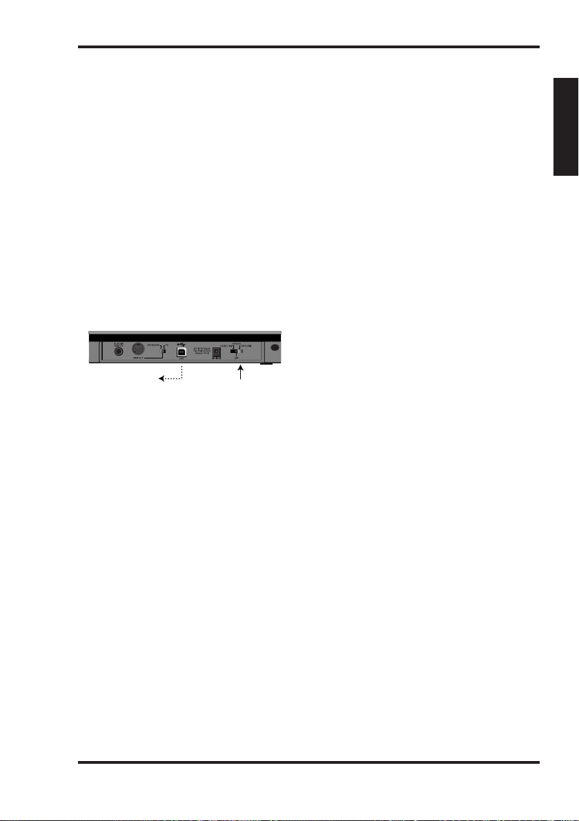
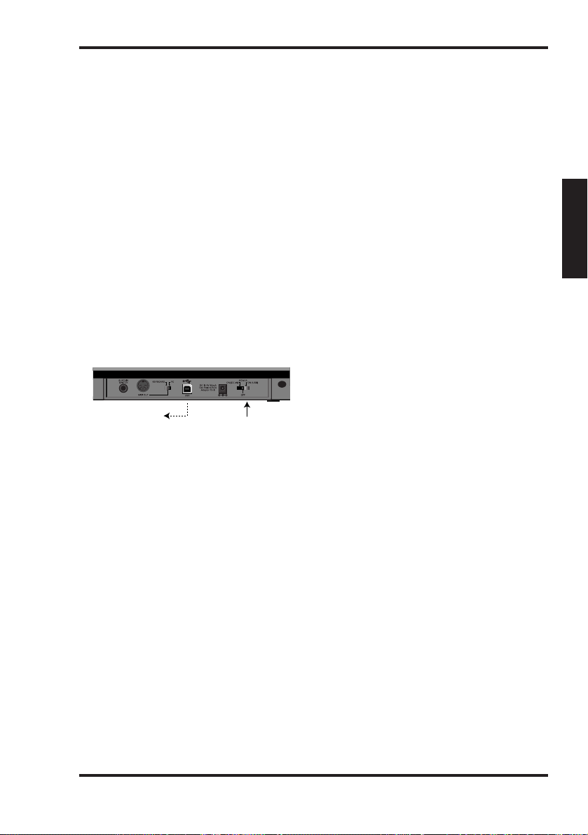
The PC-300 can be powered using the
supplied adapter, or via a USB connection
with your computer.
Power supply
Using the USB power supply
1.
Connect the PC-300’s USB port to a
free USB port of your PC (see page 10).
This requires the use of the supplied USB
cable.
2.
Switch on your computer.
Using the supplied adapter
Note: Be sure to use only the specified AC
adapter (ACA series). Using any other type
may cause malfunction or electric shock.
Note: If the unit is to remain unused for an
extended period of time, unplug the power
cord.
1.
Check that the PC-300 is OFF.
2.
Connect the AC adapter to the DC IN
jack, and the other end to a power outlet.
Set to "ON (USB)"
To a USB connector of
you computer
ENGLISH
Page 10
Setting up the PC-300
The PC-300 is a MIDI controller. It contains no sound-generating circuitry of its own, but
it can effectively control external units (sound module, computer, etc.) by transmitting a
wide variety of MIDI messages.
To ensure maximum benefit from your system, be sure to read this manual and the manuals for the external equipment you are using.
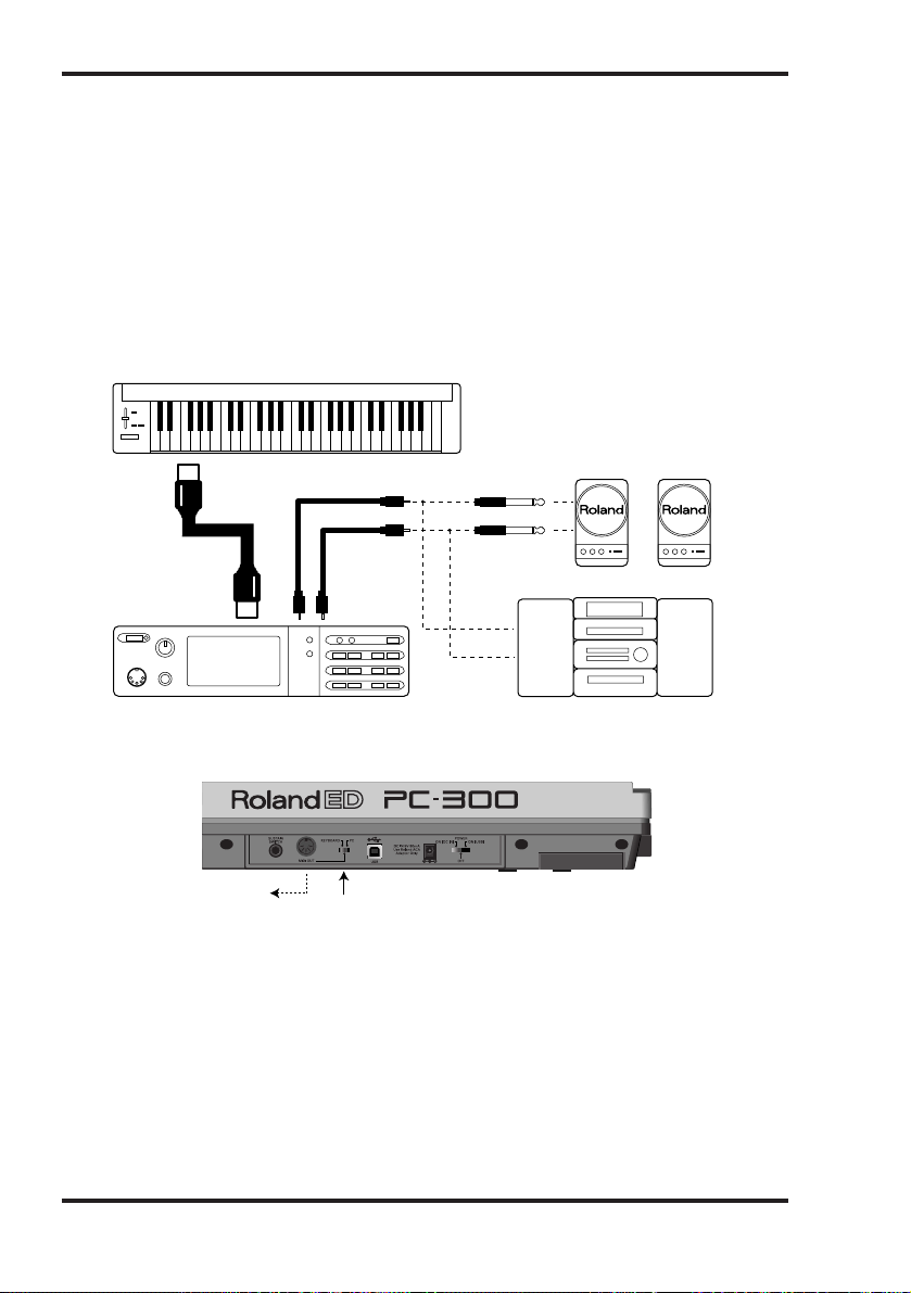
Controlling other MIDI devices
1.
Connect the PC-300’s MIDI OUT port to the MIDI IN connector on the sound module
you wish to control.
2.
Set the PC-300’s KEYBOARD/PC switch to “KEYBOARD”.
Desk Top Music setup
When connecting your computer with a sound module via a serial connection, use only a
serial cable which is designed for the model of computer you are using and its particular
kind of connector.
If the sound module has a COMPUTER/TO HOST switch, be sure to set it to the appropriate position. This will vary depending on the type of computer, the way you are connecting
it, and the requirements of the software you are using.
Select "KEYBOARD"
To MIDI IN of the
sound module
MIDI OUT
connector
MIDI IN
connector
PC-300
Sound module
Stereo set, etc.
OUTPUT jacks
Monitor speakers
(powered)
INPUT jacks
LINE IN,
AUX, or TAPE IN
8
PC-300
Page 11
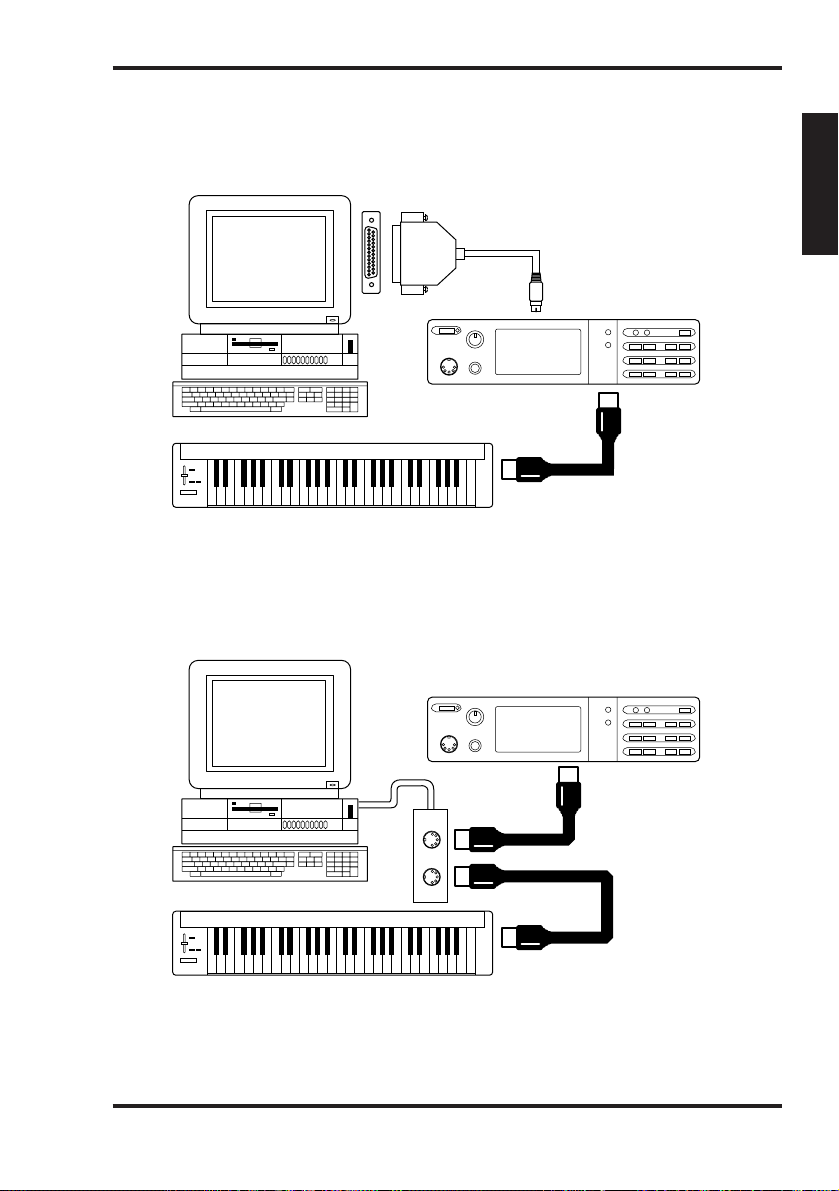
Computer connected using the serial connector on the sound module
1.
Connect the PC-300’s MIDI OUT port to the MIDI IN connector on the sound module
you wish to control.
2.
Set the PC-300’s KEYBOARD/PC switch to “KEYBOARD”. See page 8.
Computer connected via the MIDI IN connector on the sound module
1.
Connect the PC-300’s MIDI OUT port to the MIDI IN connector on the MIDI process-
ing unit (MPU series, sound card, or the like).
2.
Set the PC-300’s KEYBOARD/PC switch to “KEYBOARD”. See page 8.
Note: This setup requires that you activate the sequencer program’s MIDI Thru/Soft Thru/MIDI
Echo function.
MIDI OUT connector
MIDI IN
connector
COMPUTER switch
(set to MIDI)
Sound module
Computer
MIDI OUT
connector
MIDI IN connector
MIDI OUT connector
COMPUTER
connector
MIDI IN
connector
RS-232C connector
COMPUTER switch
(set to PC-2)
PC-300
Sound module
Computer
Computer cable
9
Owner’s Manual
ENGLISH
Page 12
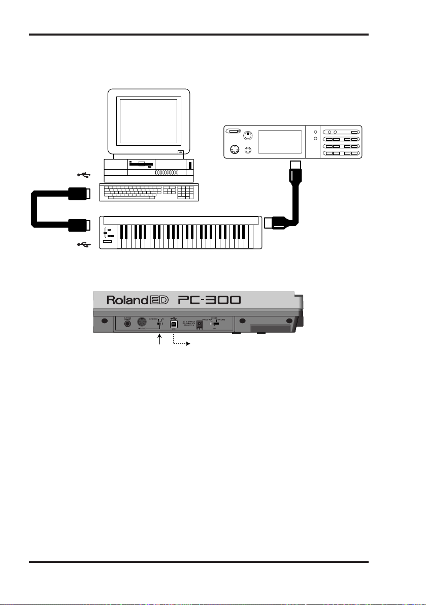
Computer connected via the USB port
1.
Connect the PC-300’s USB port to a free USB port on your computer.
2.
Set the PC-300’s KEYBOARD/PC switch to “PC”.
Powering up
1.
Power to the various devices should be turned on in the appropriate order:
• First, switch on the units from which MIDI messages will originate (here, the PC-300).
The PC-300’s POWER indicator lights.
Note: If the PC-300 is powered using the ACA series adapter, set the POWER switch to the “ON
(DC IN)” position. If it is connected to a USB port, set the POWER switch to the “ON (USB)”
position. In that case, there is no need for the adapter.
• Next, switch on the sound module, then the audio reproduction equipment.
2.
Power off your system in the reverse order.
Note: This unit is equipped with a circuitry protection feature. A brief interval after power up is
required before the unit will operate normally.
Select "PC"
To a USB port of
your computer
MIDI IN
connector
COMPUTER switch
(set to MIDI)
PC-300
Sound module
Computer
MIDI OUT
connector
USB connector
USB connector
10
PC-300
Page 13

Setting the MIDI transmit
channel
To control the sound module, set the
PC-300’s MIDI channel to the same channel on which the module is receiving. If
the sound module is multitimbral, set the
channel on the PC-300 so it matches the
MIDI channel of the module’s Part that
you wish to control.
[Procedure]
1.
Press MIDI/SELECT [3] (the LED will
light).
2.
Select the MIDI channel by pressing
one of the MIDI CHANNELS keys [6].
3.
Press MIDI/SELECT [3] again (the LED
will go out).
Selecting sounds
Program Change/Bank Select messages are
used for changing Tones for an instrument
Part, and for changing Drum Sets for the
Drum Part (MIDI channel 10).
Changing sounds in a GS sound module
To change Tones in a GS module, you
need to send Bank Select messages using
control changes CC00 (called “H” here)
and CC32 (called “L”), followed by the
desired Program Number (PC).
The desired sound bank needs to be specified using both an “H”and an “L” value.
Be aware that only sending these two messages is not enough for selecting another
sound. You also need to transmit a
Program Change number.
On the PC-300, these three messages are
always sent as one set:
• Value of control change CC00 (“H”);
• Value of control change CC32 (“L”);
• Program Number.
Note: You can refer to the GS/GM sound
group list printed on the upper-right part of
the PC-300’s panel when specifying a Program
Number. See also the manual of the module
your are using.
[Procedure]
1.
Set the MIDI transmit channel to
match that of the Part or module you
wish to control.
See “Setting the MIDI transmit channel”.
2.
Press MIDI/SELECT [3] (the LED will
light).
3.
Press the black G#4 key (“H”) [9].
4.
Set the “H”value (CC00) by pressing
the appropriate keys in the NUMERIC
ENTRY section [12].
For single-digit program numbers (1~9),
pressing the corresponding key is enough.
Note: Press the [CANCEL] key [13] to erase
these values and start again.
5.
Press ENTER [14].
6.
Press the black F#4 key (“L”) [9].
7.
Set the “L” value (CC32) by pressing the
appropriate keys in the NUMERIC
ENTRY section [12].
For single-digit program numbers (1~9),
pressing the corresponding key is enough.
8.
Press ENTER [14].
9.
Press the black A#4 key (“Program
Change”) [10].
10.
Select the program number by pressing the appropriate keys in the NUMERIC
ENTRY section [12].
11.
Press ENTER [14].
12.
Press MIDI/SELECT [3] again (the
LED will go out).
11
Owner’s Manual
ENGLISH
Page 14

[Example]
Selecting Variation 8, instrument 3 (Piano
3w) on an SC-8850:
1.
Set the MIDI transmit channel to
match that of the Part or module you
wish to control.
2.
Press MIDI/SELECT [3] (the LED will
light).
3.
Press the black G#4 key (“H”) [9].
4.
Press the “8” key in the NUMERIC
ENTRY section [12].
5.
Press ENTER [14].
6.
Press the black F#4 key (“L”) [9].
7.
Press the “0” key in the NUMERIC
ENTRY section [12].
Note: “L” corresponds to CC32. This Bank
Select message is sometimes used for selecting
other sound module modes. If so, several “L”
values are supported. See the module’s manual
for details.
8.
Press ENTER [14].
9.
Press the black A#4 key (“Program
Change”) [10].
10.
Press the “3” key in the NUMERIC
ENTRY section [12].
11.
Press ENTER [14].
12.
Press MIDI/SELECT [3] again (the
LED will go out).
Selecting Drum Sets on a GS
sound module
The Drum Part (MIDI channel 10) of a
GS module does not respond to Bank
Select messages. However, if you try to
send only a Program Change message
from the PC-300, a Bank Select message
will end up being transmitted along with
it anyway because the data for the last
sound specified will have been retained in
memory. For this reason, you should
always send the value “0” for “H” and “L”,
followed by the Program Number in order
to make sure you obtain the Drum Set you
need.
Note: “L” corresponds to CC32. This Bank
Select message is sometimes used for selecting
other sound module modes. If so, several “L”
values are supported. See the module’s manual
for details.
[Procedure]
1.
Set the MIDI transmit channel to 10.
See page 11.
2.
Press MIDI/SELECT [3] (the LED will
light).
3.
Press the black G#4 key (“H”) [9].
4.
Press the “0” key (C#5) in the NUMER-
IC ENTRY section [12].
Note: Press the [CANCEL] key [13] to erase
these values and start again.
5.
Press ENTER [14].
6.
Press the black F#4 key (“L”) [9].
7.
Press the “0” key (C#5) in the NUMER-
IC ENTRY section [12].
8.
Press ENTER [14].
9.
Press the black A#4 key (“Program
Change”) [10].
10.
Select the program number by pressing the appropriate keys in the NUMERIC
ENTRY section [12].
Example: to select the PC #49 Drum Set
(ORCHESTRA Set) on an SC-8850, Press
the “4” and then the “9” key.
11.
Press ENTER [14].
12.
Press MIDI/SELECT [3] again (the
LED will go out).
12
PC-300
Page 15

7. Various useful functions
13
Owner’s Manual
Temporarily changing the pitch
of a note (Pitch Bend)
Move the BENDER/MODULATION lever
[1] left or right to transmit Pitch Bend
messages, and apply subtle pitch changes
to the notes you are playing.
Note: The Pitch Bend range (amount of pitch
change) varies depending on the setting of the
Part or module being controlled.
Adding vibrato (Modulation)
Moving the BENDER/MODULATION
lever [1] forward (away from you) will
transmit Modulation messages (CC01),
changing the sound in real time (usually
by adding a vibrato effect).
Note: The change obtained with this message
will vary depending on the settings for your
sound module. In some cases, the filter or volume will be modulated, producing a WahWah
or tremolo effect.
Holding the notes your play
(Sustain)
Connect an optional DP-2, DP-6 or BOSS
FS-5U footswitch to the SUSTAIN
SWITCH jack. Press it while playing one
or several notes to send Hold 1 messages
(CC64), causing the notes to be sustained.
If an electric organ or another sustained
sound is used, the notes will continue for
as long as you have the pedal down.
Pressing the pedal will transmit an ON
value (127), while releasing it will transmit
an OFF value (0).
Note: The CC 64 (Hold 1) function can be
assigned to the DATA ENTRY slider, allowing
you to obtain the damper effect by moving the
slider.
ENGLISH
Page 16

8. Changing octaves
14
PC-300
Standard (no OCTAVE SHIFT)
C2 (36)
C6 (84)
C3 (48) C7 (96)
OCTAVE SHIFT: +2 octaves
C4 (60)
C8 (108)
OCTAVE SHIFT: +3 octaves
C5 (72)
C9 (120)
OCTAVE SHIFT: +4 octaves
C6 (84)
G9 (127)
OCTAVE SHIFT: +1 octave (UP)
Standard (no OCTAVE SHIFT)
C2 (36)
C6 (84)
C1 (24) C5 (72)
OCTAVE SHIFT: –2 octaves
C0 (12)
C4 (60)
OCTAVE SHIFT: –3 octaves
C–1 (0)
C3 (48)
OCTAVE SHIFT: –1 octave (DOWN)
Using the OCTAVE [5] buttons ([+],
[–]), the soundable range of the keyboard can be shifted up or down,
allowing you to access notes that lie
beyond the range covered by the
PC-300’s 49 keys.
Selecting a higher octave: OCTAVE
[+]
Press [+] once to raise the note numbers transmitted by the keyboard by
one octave. Repeat this to shift the
keyboard two octaves higher. By
pressing this button four times, you
can raise the keyboard’s pitch by 4
octaves.
Note: When shifting the keyboard 4
octaves up, the gray keys do not
transmit notes messages.
Selecting a lower octave: OCTAVE
[–]
Press [–] once to lower the note numbers transmitted by the keyboard by
one octave. As you can see, this will
shift the C2 one octave to the right,
while the C6 is no longer available.
Repeat this procedure to lower the
pitch by up to 3 octaves.
Returning to the normal sound
range: STANDARD
Press [+] and [–] simultaneously.
Page 17
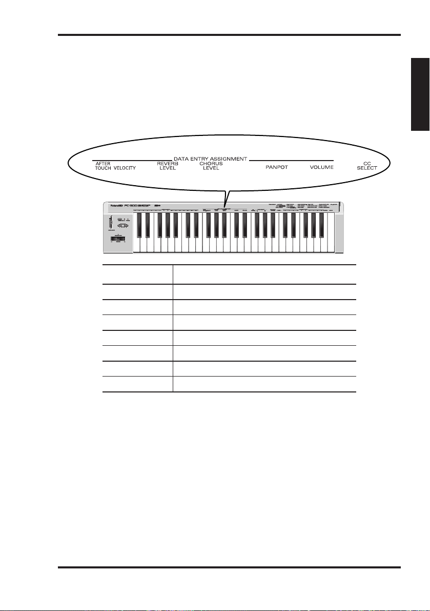
9. Controlling a sound module with the DATA
ENTRY slider
The following functions can be assigned to the DATA ENTRY slider:
15
Owner’s Manual
Note: In some cases, moving the slider only
slightly may not produce any noticeable
change. If this happens, move the slider up
and down once, then set the value.
Altering the timbre (Channel
Aftertouch)
The PC-300’s keyboard does not transmit
Channel Aftertouch messages. You can,
however, achieve a similar result by assigning Channel Aftertouch to the DATA
ENTRY slider and moving it up and down
to obtain the desired effect.
Channel Aftertouch is a function that lets
you alter notes (that have already been
played) by applying additional pressure on
the keys.
1.
Set the MIDI transmit channel to
match that of the Part or module you
wish to control.
See “Setting the MIDI transmit channel”
on page 11.
2.
Press MIDI/SELECT [3] (the LED will
light).
Function name Description
Channel Aftertouch Alters the notes currently being played (volume, pitch, filter)
Velocity Changes the dynamics (timbre, volume)
Reverb Level (CC 91) Sets the depth of the Reverb effect
Chorus Level (CC 93) Sets the depth of the Chorus effect
Panpot (CC 10) Sets the sound position (localization in the stereo sound field)
Volume (CC 07) Sets the volume level of the Part
CC Select Depends on the selected controller number
ENGLISH
Page 18

3.
Press the white F3 key (AFTER
TOUCH) in the DATA ENTRY ASSIGNMENT section [7].
4.
Press MIDI/SELECT [3] again (the LED
will go out).
Now, when you move the DATA ENTRY
slider, Channel Aftertouch messages (with
a value reflecting the slider’s position) will
be transmitted.
Note: A GS sound module only responds to
Aftertouch messages if you change its default
setting. Computer users should consult the
owner’s manual of their software, since it may
be possible to assign Channel Aftertouch to the
desired function (volume, pitch, filter) from
within the software.
Changing the velocity
sensitivity
Whenever a key is pressed, the PC-300 not
only transmits the corresponding note
number but also a value describing how
hard you pressed the key. The VELOCITY
function allows you to set the range of
transmitted velocity messages.
1.
Set the MIDI transmit channel to
match that of the Part or module you
wish to control.
See “Setting the MIDI transmit channel”
on page 11.
2.
Press MIDI/SELECT [3] (the LED will
light).
3.
Press the black F#3 key (VELOCITY).
4.
Press MIDI/SELECT [3] again (the LED
will go out).
Move the DATA ENTRY slider to select the
velocity sensitivity value. With the slider at
its maximum, velocity values within the
entire 1~127 range can be transmitted.
Reverb level
This function allows you to set the Reverb
depth for the Part or module you are controlling, and thus to specify how much
Reverb will be added to the Part’s sound.
1.
Set the MIDI transmit channel to
match that of the Part or module you
wish to control.
See “Setting the MIDI transmit channel”
on page 11.
2.
Press MIDI/SELECT [3] (the LED will
light).
3.
Press the black G#3 key (REVERB
LEVEL).
4.
Press MIDI/SELECT [3] again (the LED
will go out).
Now you can use the DATA ENTRY slider
to set the Reverb Send Level (Effect 1
Depth, CC91) of the receiving Part or
module.
Note: On a sound module other than a GS or
General MIDI module, the relevant parameter
may not correctly respond to CC91 messages.
Chorus level
This function allows you to set the Chorus
depth for the Part or module you are controlling.
1.
Set the MIDI transmit channel to
match that of the Part or module you
wish to control.
See “Setting the MIDI transmit channel”
on page 11.
2.
Press MIDI/SELECT [3] (the LED will
light).
3.
Press the black A#3 key (CHORUS
LEVEL).
4.
Press MIDI/SELECT [3] again (the LED
will go out).
Now you can use the DATA ENTRY slider
16
PC-300
Page 19

to set the Chorus Send Level (Effect 3
Depth, CC93) of the receiving Part or
module.
Note: On a sound module other than a GS or
General MIDI module, the relevant parameter
may not correctly respond to CC93 messages.
Setting the sound location:
Panpot
When the module is connected in stereo,
this parameter determines the stereo
placement (L/R) of the individual sounds
produced. For the Drum Part (MIDI
channel 10), it shifts the overall stereo
placement of percussive instruments (the
overall orientation of the Drum Part on a
GS module).
1.
Set the MIDI transmit channel to
match that of the Part or module you
wish to control.
See “Setting the MIDI transmit channel”
on page 11.
2.
Press MIDI/SELECT [3] (the LED will
light).
3.
Press the black C#4 key (PANPOT) in
the DATA ENTRY ASSIGNMENT section
[7].
4.
Press MIDI/SELECT [3] again (the LED
will go out).
Now you can use the DATA ENTRY slider
to set the Panpot value to be transmitted.
With the slider at the center, the sound
will be oriented in the center. When pulled
all the way forward, the sound will be
heard from the extreme right. When
pushed completely back, the sound will
come from the left.
Note: The Panpot settings work just the other
way around on modules such as the Roland
MT-32, TD-8, and certain others.
Changing the volume
This function allows you to adjust the volume level for the Part you are controlling.
1.
Set the MIDI transmit channel to
match that of the Part or module you
wish to control.
See “Setting the MIDI transmit channel”
on page 11.
2.
Press MIDI/SELECT [3] (the LED will
light).
3.
Press the black D#4 key (VOLUME).
4.
Press MIDI/SELECT [3] again (the LED
will go out).
Now you can use the DATA ENTRY slider
to set the volume (CC07) of the part being
controlled.
If notes are stuck: Panic
The PC-300 also features a PANIC function that allows you to transmit a series of
MIDI messages that will silence the receiving instruments in case some notes go on
sounding forever:
1.
Press MIDI/SELECT [3] (the LED will
light).
2.
Simultaneously press the white B4 and
C5 keys (“PANIC”) [11].
This will cause the PC-300 to transmit socalled “Reset” data:
• Note-off for all note numbers (0~127)
on all MIDI channels;
• Reset All Controllers on all MIDI chan-
nels.
17
Owner’s Manual
ENGLISH
Page 20

Assigning other control changes to the DATA ENTRY slider
The above messages (Panpot,Volume, etc.) are the basic control change numbers almost
any module receives. There may, however, be other parameters you wish to control in realtime. To do so, assign the control change number of the desired parameter to the DATA
ENTRY slider, and do your thing.
Any controller between CC00 and CC127 can be assigned. Since the PC-300 isn’t equipped
with a display that allows you to monitor the data being transmitted, it is probably not
suited for Registered or Non-Registered Parameter Numbers (RPN or NRPN). Also note
that CC00 and CC32 are usually used as Bank Select messages and that sending a value for
these controllers without a subsequent Program Change number may have no effect at all.
Controllers 00 through 95 (continuous controllers)
18
PC-300
CC . . . . . .Control Function
00 . . . . . . .Bank Select MSB (“H”)
01 . . . . . . .Modulation
02 . . . . . . .Breath Controller
03 . . . . . . .Undefined
04 . . . . . . .Foot Controller
05 . . . . . . .Portamento Time
06 . . . . . . .Data Entry (Used with RPN/NRPN)
07 . . . . . . .Main Volume
08 . . . . . . .Balance
09 . . . . . . .Undefined
10 . . . . . . .Panpot
11 . . . . . . .Expression Pedal
12 . . . . . . .Effect Control 1
13 . . . . . . .Effect Control 2
14~15 . . . .Undefined
16 . . . . . . .General Purpose Controller 1
17 . . . . . . .General Purpose Controller 2
18 . . . . . . .General Purpose Controller 3
19 . . . . . . .General Purpose Controller 4
20~31 . . . .Undefined
32 . . . . . . .Bank Select LSB (“L”)
33~63 . . . .LSB for controllers 1-31
64 . . . . . . .Hold 1 (Damper)
65 . . . . . . .Portamento
66 . . . . . . .Sostenuto
67 . . . . . . .Soft Pedal
68 . . . . . . .Undefined
69 . . . . . . .Hold 2 (Freeze)
70~79 . . . .Undefined
80 . . . . . . .General Purpose Controller 5
81 . . . . . . .General Purpose Controller 6
82 . . . . . . .General Purpose Controller 7
83 . . . . . . .General Purpose Controller 8
84~90 . . . .Undefined
91 . . . . . . .Effect 1 (External Effect) Depth
(GS/General MIDI: Reverb Send
Level)
92 . . . . . . .Effect 2 (Tremolo) Depth
93 . . . . . . .Effect 3 (Chorus) Depth
(GS: Chorus Send Level)
94 . . . . . . .Effect 4 (Celeste) Depth
95 . . . . . . .Effect 5 (Phaser) Depth
CC96 and above (NRPN/RPN, Channel Mode Messages)
CC . . . . . .Control Function
96 . . . . . . .Data Increment
97 . . . . . . .Data Decrement
98 . . . . . . .Non-Registered Parameter Number
LSB
99 . . . . . . .Non-Registered Parameter Number
MSB
100 . . . . . .Registered Parameter Number LSB
101 . . . . . .Registered Parameter Number MSB
102~120 . .Undefined
121~127 . .Reserved for Channel Mode
Messages
Page 21

[Assigning a control change]
1.
Set the MIDI transmit channel to
match that of the Part or module you
wish to control.
See “Setting the MIDI transmit channel”
on page 11.
2.
Press MIDI/SELECT [3] (the LED will
light).
3.
Press the white F4 key (CC SELECT)
[8].
4.
Select the Controller Number by pressing keys in the NUMERIC ENTRY section
[12].
5.
Press ENTER [14].
6.
Press MIDI/SELECT [3] again (the LED
will go out).
Now you can use the DATA ENTRY slider
to transmit values for the specified
Controller Number.
19
Owner’s Manual
10. Troubleshooting
Q: The PC-300 cannot be switched on or
doesn’t work at all.
A: Check if you are using the correct AC
adapter. (Use only the specified adapter).
A: Check the setting of the POWER switch:
set it to “ON (DC IN)” if you are using
the supplied adapter, and to “ON (USB)”
when powering the PC-300 via the USB
connector. Do not forget to establish a
USB connection with your computer.
Q: The sound module does not respond to the
movements of the DATA ENTRY slider.
A: Check whether the correct function is
assigned to the DATA ENTRY slider.
Also, note that the module will sometimes not respond if the slider is moved
only slightly. If you are unsure, pull the
slider all the way down first and then set
it to the desired position.
A: Check the PC-300’s MIDI transmit
channel (see page 11) and set it so that it
corresponds to the Part’s or module’s
receive channel.
Q: The sound you have requested cannot be
selected.
A: Some GS modules, such as those in the
Sound Canvas series, have a switch
which allows you to turn on or off the
reception of Program Change messages
and/or Bank Select messages. Be sure this
switch is turned ON.
A: Could the sound module have received a
GM System On message (the message
that tells a module to function as a
General MIDI sound module) before
you sent Bank Select messages? Since
Bank Selects are not recognized by the
General MIDI System Level 1 specifications, the module will ignore them if it is
currently behaving as a General MIDI
device. To correct this situation, send a
GS Reset message (which retrieves the
GS default settings), or simply switch the
module off, then on again.
Note: The PC-300 cannot transmit GS Reset
messages.
A: Did you transmit the complete sequence
of values (“H”, “L” and Program
Number)? The PC-300 always transmits
CC00/CC32/PC clusters, even if only the
ENGLISH
Page 22

Program Number has been specified.
Note also that the Bank Select values are
memorized until the next sound has
been successfully selected. So, if even one
out of the complete set of three values is
mistakenly not supplied, part of the previous values could be sent along with the
newly specified ones. As a result, you
might not obtain the sound you need.
A: Does your computer music application
use Program Numbers 0~127 for sound
selection? Since the PC-300 uses numbers 1~128, you may need to add one to
the number being selected to obtain the
correct sound.
Q: The GS module does not respond to
Aftertouch messages.
A: By default, a GS sound module does not
respond to Aftertouch messages.
Therefore, you need to set the Aftertouch
parameters using Exclusive messages.
(Refer to the MIDI Implementation for
the sound module in question.) If using
a computer-based system, you may be
able to easily make the required settings
using the software.
20
PC-300
11. Specifications
Keyboard
49 keys (velocity sensitive)
MIDI control
MIDI Channels (1~16)
Octave Shift (Up/Down, Standard, all note
numbers between 00 and 127)
Bender/Modulation lever
Data Entry slider: Controller Numbers
00/32 (GS Variation selection), Channel
Aftertouch, Velocity, Reverb Send Level,
Chorus Send Level, Volume, Panpot, CC
Select (control change numbers
CC00~127)
Rear panel
Power Switch, Sustain Switch jack, AC IN
jack, MIDI OUT connector, USB connector, KEYBOARD/PC switch
Power supply
DC 9 V: AC adapter, USB
Current draw
80 mA
Dimensions
816 (W) x 175 (D) x 80 (H) mm
32-1/8 x 6-15/16 x 3-3/16 inches
Weight
2.5 kg / 5 lbs 9 oz
Accessories
Owner’s Manual, MIDI cable, USB cable,
adapter
Options
DP-2/DP-6 Footswitch
Note: In the interest of product development,
the specifications and/or appearance of this
unit are subject to change without prior
notice.
Page 23
Herzlichen Glückwunsch und vielen Dank, dass Sie sich für das PC-300 MIDI-Keyboard
von Roland entschieden haben.
Das PC-300 ist ein anwenderfreundliches MIDI-Keyboard für GS-kompatible Module mit
einem USB-Anschluss. Der Vorteil dieses Anschlusstyps ist, dass das PC-300 auch über die
USB-Verbindung mit Strom versorgt werden kann und zugleich kompatibel ist mit dem
neuen Standard für sowohl IBM PC-kompatible als auch Macintosh® Computer.
Bitte lesen Sie sich diese Bedienungsanleitung vollständig durch, um alle gebotenen
Funktionen kennenzulernen und über Jahre hinaus Freude an Ihrem PC-300 zu haben.
Bedienungsanleitung
1
Copyright © 2000 Roland Europe Spa
Alle Rechte vorbehalten. Nachdruck oder Vervielfältigung jeglicher Art dieser Bedienungsanleitung
ist ohne die schriftliche Genehmigung von Roland Europe S.p.a. nicht erlaubt.
DEUTSCH
Page 24

1. Inhalt
2
PC-300
2. Vorstellung des PC-300 . . . . . . . . . . . . . . . . . . . . . . . . . . . . . . . . . . . . . . . . . . . . . .3
Was ist das GS-Format (g)? . . . . . . . . . . . . . . . . . . . . . . . . . . . . . . . . . . . . . . . . . . . . .3
3. Wichtigste Funktionen des PC-300 . . . . . . . . . . . . . . . . . . . . . . . . . . . . . . . . . . . . .4
4. Wichtige Hinweise . . . . . . . . . . . . . . . . . . . . . . . . . . . . . . . . . . . . . . . . . . . . . . . . . .5
5. Vorder- und Rückseite . . . . . . . . . . . . . . . . . . . . . . . . . . . . . . . . . . . . . . . . . . . . . . .6
6. Anschließen und Einstellen des PC-300 . . . . . . . . . . . . . . . . . . . . . . . . . . . . . . . . .7
Stromversorgung . . . . . . . . . . . . . . . . . . . . . . . . . . . . . . . . . . . . . . . . . . . . . . . . . . . . . . .7
Anschließen des PC-300 . . . . . . . . . . . . . . . . . . . . . . . . . . . . . . . . . . . . . . . . . . . . . . . . .8
Einschalten der Anlage . . . . . . . . . . . . . . . . . . . . . . . . . . . . . . . . . . . . . . . . . . . . . . . . .10
Einstellen des MIDI-Übertragungskanals . . . . . . . . . . . . . . . . . . . . . . . . . . . . . . . . . .11
Klangauswahl . . . . . . . . . . . . . . . . . . . . . . . . . . . . . . . . . . . . . . . . . . . . . . . . . . . . . . . . .11
Auswahl eines Drum Sets für ein GS-Modul . . . . . . . . . . . . . . . . . . . . . . . . . . . . . . . .12
7. Funktionen für ein expressiveres Spiel . . . . . . . . . . . . . . . . . . . . . . . . . . . . . . . . .13
Beugen der gespielten Noten (Pitch Bend) . . . . . . . . . . . . . . . . . . . . . . . . . . . . . . . . .13
Hinzufügen von Vibrato (Modulation) . . . . . . . . . . . . . . . . . . . . . . . . . . . . . . . . . . . .13
Halten der gespielten Noten (Sustain) . . . . . . . . . . . . . . . . . . . . . . . . . . . . . . . . . . . . .13
8. Ändern der Oktavlage . . . . . . . . . . . . . . . . . . . . . . . . . . . . . . . . . . . . . . . . . . . . . .14
9. Ansteuern des Moduls mit dem DATA ENTRY-Regler . . . . . . . . . . . . . . . . . . . . . .15
Ändern der Klangfarbe (Kanal-Aftertouch) . . . . . . . . . . . . . . . . . . . . . . . . . . . . . . . . .15
Ändern der Anschlagempfindlichkeit . . . . . . . . . . . . . . . . . . . . . . . . . . . . . . . . . . . . .16
Reverb Level . . . . . . . . . . . . . . . . . . . . . . . . . . . . . . . . . . . . . . . . . . . . . . . . . . . . . . . . . .16
Chorus Level . . . . . . . . . . . . . . . . . . . . . . . . . . . . . . . . . . . . . . . . . . . . . . . . . . . . . . . . .16
Einstellen der Stereoposition: Panpot . . . . . . . . . . . . . . . . . . . . . . . . . . . . . . . . . . . . . .17
Ändern der Lautstärke . . . . . . . . . . . . . . . . . . . . . . . . . . . . . . . . . . . . . . . . . . . . . . . . . .17
Bei Notenhängern: Panic . . . . . . . . . . . . . . . . . . . . . . . . . . . . . . . . . . . . . . . . . . . . . . . .17
Andere Steuerbefehle für den DATA ENTRY-Regler . . . . . . . . . . . . . . . . . . . . . . . . . .18
10. Beheben kleiner Störungen . . . . . . . . . . . . . . . . . . . . . . . . . . . . . . . . . . . . . . . . .19
11. Technische Daten . . . . . . . . . . . . . . . . . . . . . . . . . . . . . . . . . . . . . . . . . . . . . . . . .20
Page 25

2. Vorstellung des PC-300
3
Bedienungsanleitung
Das PC-300 MIDI-Keyboard von Roland
ist ein Controller, mit welchem Bank- und
Programmwechselbefehle sowie eine ganze
Reihe anderer MIDI-Befehle (darunter
Reverb- und Chorus-Meldungen) zu
externen Modulen übertragen werden
können. Es enthält keine interne
Klangerzeugung, eignet sich aber zum
Steuern von Modulen, die das GS-Format
unterstützen. (Im weiteren Verlauf wollen
wir dieses schlicht “GS-Module” nennen.)
Was ist das GS-Format (g)?
Das GS-Format stellt eine Ergänzung zur
MIDI-Norm dar, die Roland für einige
seiner Module entwickelt hat. Das GSFormat bezieht sich auf die Art, wie
elektronische Instrumente die
empfangenen MIDI-Befehle auswerten.
Alle zum GS-Format kompatiblen
Instrumente führen das GS-Logo und
haben den Vorteil, dass sie sich bei
Empfang der vom PC-300 gesendeten
MIDI-Daten gleich verhalten.
Anmerkung: Alle GS-Module von Roland sind
außerdem hundertprozentig General MIDI
Level 1-kompatibel (
m).
1990 wurde die MIDI-Norm dahingehend
erweitert, dass neben Klangspeichern auch
Klangbänke angewählt werden können
(die Bankanwahl erfolgt mit den
Steuerbefehlen CC00 und CC32, während
die Klanganwahl weiterhin von den
Programmwechsel-Befehlen geregelt
wird). Das GS-Format unterstützt dieses
vielseitigere System.
Klangspeicherstruktur eines GS-Moduls
Ein GS-Modul bietet 128 Basisklänge (die
“Capitals”) sowie eine Reihe von
Klangvariationen. Die Zuordnung der
Basisklänge zu den Programmnummern
entspricht dem General MIDI-System
(Level 1). Die Capitals befinden sich in
Bank 0, während sich die Variationen in
den Bänken 1~127 befinden. Welche
Variationen genau belegt sind, richtet sich
nach dem jeweiligen Modell. Am besten
legen Sie die Bedienungsanleitung des
verwendeten Moduls in Griffweite.
Die “Drum Sets” eines GS-Moduls
MIDI-Kanal 10 (der “Schlagzeugkanal”)
bietet neben dem am häufigsten
verwendeten Standard Set
(Programmnummer PC01) mehrere
Schlagzeugvariationen. Auch die Drum
Sets (Schlagzeugklänge) kann man mit
Programmwechseln aufrufen. Da sich das
Drum Set-Angebot ebenfalls nach dem
verwendeten Modul richtet, schauen Sie
bitte in der Bedienungsanleitung Ihres
Instrumentes nach, welche Drum Sets
belegt sind.
Anmerkung: In bestimmten Fällen ist der
verlangte Variationsklang bzw. das Variation
Drum Set auf dem Empfänger nicht belegt. Je
nach dem verwendeten Empfängermodul
werden die Noten dann entweder überhaupt
nicht oder nicht mit dem gewünschten Klang
(den gewünschten Schlagzeugklängen)
gespielt.
DEUTSCH
Page 26

3. Wichtigste Funktionen des PC-300
4
PC-300
USB-Anschluss
Das PC-300 ist mit einer USB-Buchse
ausgestattet und kann also direkt mit
einem IBM-kompatiblen PC oder
Macintosh®-Computer (iMac®, G4 usw.)
verbunden werden. USB erlaubt nicht nur
einen schnellen Datentransfer, sondern
auch die Stromversorgung der
angeschlossenen Geräte.
USB-Treiber
Zum Lieferumfang des PC-300 gehören
mehrere USB-Treiber für sowohl IBMkompatible als auch Macintosh®-Com-
puter. Alles Weitere hierzu erfahren Sie in
dem beiliegenden Heft.
Ausgesprochen musikalisch
Dank des anschlagdynamischen 49Tastenmanuals können Sie mit dem
PC-300 ausdrucksstark musizieren.
Außerdem bietet das PC-300 eine
Oktavierungsfunktion, mit der man den
Notenbereich nach links oder rechts
verschieben kann. Schließlich sind auch
ein Pitch Bend/Modulation-Hebel sowie
eine Anschlussbuchse für ein Haltepedal
(SUSTAIN SWITCH) belegt.
Umfassende MIDI-Kontrolle
Mit dem PC-300 kann man Klänge
externer Module anwählen, indem man
Programm- und Bankwechselbefehle
sendet (Bankwechsel= Steuerbefehle CC00
und CC32). Es kann also jeder beliebige
GS-Klang aufgerufen werden.
Darüber hinaus kann man dem DATA
ENTRY-Regler eine große Anzahl von
MIDI-Steuerbefehlen zuordnen und den
gewünschten Parameter (Hall- oder
Chorus-Tiefe zum Beispiel) dann bequem
mit dem Regler einstellen.
Macht DTM (Desk Top Music)
noch schöner
Dank seiner kompakten Abmessungen,
passt das PC-300 bestimmt auf Ihren
Schreibtisch. Es wird mit Sicherheit ein
wichtiger Bestandteil Ihrer
Computermusik-Anlage. Das PC-300
erlaubt nicht nur, eigene Stücke in Echtzeit
oder Schritt für Schritt aufzuzeichnen,
sondern auch die Melodie zu einem
Standard MIDI File zu spielen (Minus
One).
Page 27

4. Wichtige Hinweise
5
Bedienungsanleitung
Verwenden Sie immer nur das empfohlene
Netzteil (ACA). Die Verwendung anderer
Netzteile kann zu Schäden oder
Stromschlägen führen.
Stromspeisung
• Schalten Sie das PC-300 sowie die übrigen
Geräte aus, bevor Sie sie miteinander verbinden.
Nur so ist sichergestellt, dass nichts beschädigt
wird.
• Stellen Sie den POWER-Schalter auf der
Rückseite immer der gewählten
Stromversorgung entsprechend (Netzteil oder
USB) ein.
• Schließen Sie das PC-300 niemals an einen
Stromkreis an, mit dem Sie bereits ein Gerät
verbunden haben, das Störspannungen
generiert.
• Die Spannungsanforderungen des PC-300
finden Sie neben dem DC IN-Anschluss sowie
auf dem Typenschild des Netzteils. Wählen Sie
immer eine Steckdose, die diesen Ansprüchen
genügt.
• Achten Sie darauf, dass das Kabel des Netzteils
nicht gequetscht wird. Stellen keine schweren
Gegenstände darauf.
• Ziehen Sie beim Lösen des Netzanschlusses
immer am Stecker und niemals am Kabel, um
das Reißen der Adern zu vermeiden.
• Wenn Sie das PC-300 längere Zeit nicht
verwenden möchten, lösen Sie am besten den
Netzanschluss.
Aufstellung
• Meiden Sie extreme Temperaturen (direktes
Sonnenlicht, Auto usw.). Stellen Sie das PC-300
nicht an einen staubigen, feuchten oder stark
vibrierenden Ort.
• Bei Verwendung des PC-300 in der Nähe einer
Endstufe usw. kann es zu Störspannungen
kommen.
• Dieses Gerät kann den Radio- bzw.
Fernsehempfang beeinträchtigen. Stellen Sie das
PC-300 notfalls woanders hin.
Pflege
• Wischen Sie das PC-300 mit einem weichen,
trockenen bzw. leicht angefeuchteten Tuch ab.
Hartnäckigen Schmutz können Sie mit einer
milden Seifenlauge entfernen. Wischen Sie das
Instrument anschließend wieder trocken.
• Verwenden Sie zum Reinigen niemals
Waschbenzin, Lösungsmittel oder Alkohol, um
das Gehäuse nicht unnötig zu beschädigen.
Weitere Vorsichtsmaßnahmen
• Behandeln Sie das PC-300 mit der gebotenen
Umsicht.
• Lassen Sie weder Metallgegenstände noch
Flüssigkeiten in das Geräteinnere gelangen.
Geschieht das doch, schalten Sie das Instrument
bitte sofort aus und wenden sich an Ihren
Roland-Händler.
• Eine leichte Erwärmung dieses Instruments
während des Betriebes ist völlig normal.
• Bevor Sie das PC-300 im Ausland verwenden,
erkundigen Sie sich bitte bei Ihrem Händler
nach der dort verwendeten Netzspannung.
• Wenn das PC-300 nicht mehr erwartungsgemäß
funktioniert, schalten Sie es sofort aus. Reichen
Sie es danach bei Ihrem Händler zur Reparatur
ein.
• Um den Garantieanspruch zu wahren, öffnen
Sie das PC-300 am besten niemals selbst.
DEUTSCH
Page 28
5. Vorder- und Rückseite
6
PC-300
[1] BENDER/MODULATION-Hebel
[2] DATA ENTRY-Regler
[3] MIDI SELECT-Taster & -Diode
[5] OCTAVE [–]/[+] Taster
[6] MIDI CHANNELS-Tasten
[7] DATA ENTRY ASSIGNMENT-Tasten
SUSTAIN SWITCHBuchse
MIDI OUTBuchse
[8] CC SELECT-Taste
[9] BANK SELECT [L] & [H] Tasten
[10] PROGRAM CHANGE-Taste
[11] PANIC-Taste
[12] NUMERIC ENTRY-Tasten
[13] CANCEL-Taste
[14] ENTER-Taste
KEYBOARD/PCBuchse
USB-Anschluss
DC INBuchse
POWER DC IN/USBSchalter
[4] POWER-Diode
Page 29
6. Anschließen und Einstellen des PC-300
7
Bedienungsanleitung
Das PC-300 kann entweder mit dem
beiliegenden Netzteil oder über eine USBVerbindung mit dem Computer mit Strom
versorgt werden.
Stromversorgung
Stromspeisung über die USB-Verbindung
1.
Verbinden Sie den USB-Anschluss des
PC-300 mit einer freien USB-Buchse Ihres
PCs (siehe Seite 10).
Verwenden Sie hierfür das beiliegende
USB-Kabel.
2.
Schalten Sie den Computer ein.
Verwendung des beiliegenden Netzteils
Anmerkung: Verwenden Sie ausschließlich das
beiliegende Netzteil (ACA-Serie). Die
Verwendung anderer Netzteile kann zu
Schäden oder sogar Stromschlägen führen.
Anmerkung: Wenn Sie das PC-300 längere
Zeit nicht verwenden möchten, lösen Sie bitte
den Netzanschluss.
1.
Schauen Sie nach, ob das PC-300
ausgeschaltet ist (OFF).
2.
Verbinden Sie das Netzteil mit der DC
IN-Buchse und dessen großen Stecker mit
einer Netzsteckdose.
Auf "ON (USB)" stellen
des Computers
DEUTSCH
Page 30

Anschließen des PC-300
Das PC-300 ist ein MIDI-Manual (Master Keyboard). Es enthält zwar keinen Tongenerator,
kann aber andere Instrumente (Soundmodule, Rechner usw.) ansteuern.
Um wirklich alle Möglichkeiten des PC-300 auszuschöpfen, lesen Sie sich am besten diese
Bedienungsanleitung sowie die Anleitung der übrigen Instrumente gründlich durch.
Ansteuern anderer MIDI-Instrumente
1.
Verbinden Sie die MIDI OUT-Buchse des PC-300 mit dem MIDI IN-Anschluss des
Soundmoduls, das Sie ansteuern möchten.
2.
Stellen Sie den KEYBOARD/PC-Schalter des PC-300 auf “KEYBOARD”.
Desk Top Music-Einsatz
Zum Verbinden des Soundmoduls mit Ihrem Rechner verwenden Sie am besten nur ein
dafür geeignetes Kabel. Erkundigen Sie sich bei Ihrem Händler nach dem richtigen
Kabeltyp.
Wenn das Soundmodul mit einem COMPUTER/TO HOST-Schalter ausgestattet ist, stellen
Sie ihn bitte den Anforderungen entsprechend ein. Das richtet sich jeweils nach dem
Rechnertyp, dem Einsatzbereich sowie den Anforderungen des verwendeten Programms.
Wählen Sie"KEYBOARD"
Zur MIDI IN-Buchse
des Soundmoduls
MIDI OUTBuchse
MIDI INBuchse
PC-300
Modul
Stereoanlage usw.
OUTPUTBuchsen
Aktivboxen
INPUT-Buchsen
LINE IN,
AUX oder TAPE IN
8
PC-300
Page 31

Serielle Verbindung des Rechners mit dem Soundmodul
1.
Verbinden Sie die MIDI OUT-Buchse des PC-300 mit dem MIDI IN-Anschluss des
Soundmoduls, das Sie ansteuern möchten.
2.
Stellen Sie den KEYBOARD/PC-Schalter des PC-300 auf “KEYBOARD”. Siehe Seite 8.
MIDI-Verbindung des Rechners mit dem Soundmodul
1.
Verbinden Sie die MIDI OUT-Buchse des PC-300 mit der MIDI IN-Buchse der MIDI-
Schnittstelle (MPU-Serie usw.).
2.
Stellen Sie den KEYBOARD/PC-Schalter des PC-300 auf “KEYBOARD”. Siehe Seite 8.
Anmerkung: Dieser Verbindungstyp setzt voraus, dass die MIDI Thru/Soft Thru/MIDI EchoFunktion des Sequenzer-Programms eingeschaltet ist.
MIDI OUT-Buchse
MIDI INBuchse
COMPUTER-Schalter
(auf MIDI stellen)
Soundmodul
Computer
MIDI OUTBuchse
MIDI IN-Buchse
MIDI OUT-Buchse
COMPUTERAnschluß
MIDI INBuchse
RS-232C-Buchse
COMPUTER-Schalter
(auf PC-2 stellen)
PC-300
Soundmodul
Computer
Computerkabel
9
Bedienungsanleitung
DEUTSCH
Page 32

USB-Verbindung mit dem Computer
1.
Schließen Sie die USB-Buchse des PC-300 an einen USB-Port des Computers an.
2.
Stellen Sie den KEYBOARD/PC-Schalter des PC-300 auf “PC”.
Einschalten der Anlage
1.
Schalten Sie die einzelnen Geräte Ihrer Anlage immer in der richtigen Reihenfolge ein:
• Schalten Sie immer zuerst die Geräte ein, die MIDI-Daten senden (hier also das PC-300).
Die POWER-Diode des PC-300 leuchtet nun.
Anmerkung: Wenn Sie das PC-300 über das beiliegende Netzteil speisen, müssen Sie den POWERSchalter auf “ON (DC IN)” stellen. Haben Sie es an einen USB-Port angeschlossen, so müssen Sie
den POWER-Schalter auf “ON (USB)” stellen. In dem Fall brauchen Sie das Netzteil nicht.
• Schalten Sie anschließend das Soundmodul, den Computer und die Aktivboxen o.ä. ein.
2.
Schalten Sie die Anlage in umgekehrter Reihenfolge wieder aus.
Anmerkung: Das PC-300 ist mit einer Schutzschaltung ausgestattet. Daher dauert es nach
Einschalten ein paar Sekunden, bis es voll funktionstüchtig ist.
Wählen Sie "PC"
Zu einem USB-Port
des Computers
MIDI INBuchse
COMPUTER-Schalter
(auf MIDI stellen)
PC-300
Soundmodul
Computer
MIDI OUTBuchse
USB-Anschluss
USB-Anschluss
10
PC-300
Page 33

Einstellen des MIDIÜbertragungskanals
Das PC-300 funktioniert nur
erwartungsgemäß, wenn es auf dem
MIDI-Kanal sendet, auf dem das
Soundmodul empfängt. Da Sie
wahrscheinlich ein multitimbrales
Soundmodul verwenden, müssen Sie den
MIDI-Kanal wählen, der dem
anzusteuernden Part zugewiesen ist.
[So wird’s gemacht]
1.
Drücken Sie den MIDI/SELECT-Taster
[3] (seine Diode leuchtet).
2.
Wählen Sie den MIDI-Kanal, indem Sie
eine MIDI CHANNELS-Taste [6]
drücken.
3.
Drücken Sie MIDI/SELECT [3] noch
einmal (die Diode erlischt).
Klangauswahl
Für die Auswahl des gewünschten Klanges
für einen Part bzw. eines Drum Sets für
den Schlagzeug-Part (MIDI-Kanal 10)
werden Bank- und ProgrammwechselBefehle gesendet.
Klangauswahl für ein GS-Modul
Um einen Klang eines GS-Moduls
anzuwählen, müssen Sie einerseits Bankwechselbefehle mit den ControllerNummern CC00 (“H”) und CC32 (“L”)
und andererseits einen ProgrammwechselBefehl (PC) senden.
Die benötigte Klangbank muss immer mit
einem “H”- und “L”-Wert angegeben
werden. Andererseits wird kein Klang
aufgerufen, wenn Sie nur diese beiden
Befehle senden. Es muss auch eine
Programmnummer übertragen werden.
Das PC-300 sendet daher immer Befehlssätze mit folgenden Elementen:
• Einen Wert für Steuerbefehl CC00 (“H”);
• Einen Wert für Steuerbefehl CC32 (“L”);
• Eine Programmnummer.
Anmerkung: Siehe die GS/GMKlangbankübersicht rechts oben auf der
Frontplatte des PC-300 für die Wahl der
benötigten Programmnummer. Siehe
außerdem die Bedienungsanleitung des
angesteuerten Moduls.
[So wird’s gemacht]
1.
Wählen Sie für das PC-300 den MIDIKanal, auf dem der gewünschte Part oder
das Modul empfängt.
Siehe “Einstellen des MIDI-
Übertragungskanals”.
2.
Drücken Sie den MIDI/SELECT-Taster
[3] (seine Diode leuchtet).
3.
Drücken Sie die Taste G#4 (“H”) [9].
4.
Stellen Sie den “H”-Wert (CC00) ein,
indem Sie die betreffenden Tasten der
NUMERIC ENTRY-Sektion [12] drücken.
Für einstellige Programmnummern (1~9)
braucht nur eine Taste gedrückt zu
werden.
Anmerkung: Drücken Sie die [CANCEL]Taste [13], wenn Sie den falschen Wert
eingegeben haben.
5.
Drücken Sie ENTER [14].
6.
Drücken Sie die schwarze F#4-Taste
(“L”) [9].
7.
Stellen Sie den “L”-Wert (CC32) ein,
indem Sie die betreffenden Tasten der
NUMERIC ENTRY-Sektion [12] drücken.
Für einstellige Programmnummern (1~9)
braucht nur eine Taste gedrückt zu
werden.
8.
Drücken Sie ENTER [14].
9.
Drücken Sie die schwarze A#4-Taste
(“Program Change”) [10].
10.
Geben Sie die benötigte
11
Bedienungsanleitung
DEUTSCH
Page 34

Programmnummer mit den Tasten der
NUMERIC ENTRY-Sektion [12] ein.
11.
Drücken Sie ENTER [14].
12.
Drücken Sie MIDI/SELECT [3] noch
einmal (die Diode erlischt).
[Beispiel]
Auswahl von Variation 8, Instrument 3
(Piano 3w) eines SC-8850:
1.
Wählen Sie für das PC-300 den MIDIKanal, auf dem der gewünschte Part oder
das Modul empfängt.
2.
Drücken Sie den MIDI/SELECT-Taster
[3] (seine Diode leuchtet).
3.
Drücken Sie die Taste G#4 (“H”) [9].
4.
Drücken Sie die Taste “8” in der
NUMERIC ENTRY-Sektion [12].
5.
Drücken Sie ENTER [14].
6.
Drücken Sie die schwarze F#4-Taste
(“L”) [9].
7.
Drücken Sie die Taste “0” in der
NUMERIC ENTRY-Sektion [12].
Anmerkung: “L” entspricht CC32. Dieser
Bankwechselbefehl wird bisweilen für die
Auswahl eines anderen Modul-Modus’
verwendet. Es werden dann mehrere “L”-
Werte unterstützt. Siehe die
Bedienungsanleitung des Moduls.
8.
Drücken Sie ENTER [14].
9.
Drücken Sie die schwarze A#4-Taste
(“Program Change”) [10].
10.
Drücken Sie die Taste “3” in der
NUMERIC ENTRY-Sektion [12].
11.
Drücken Sie ENTER [14].
12.
Drücken Sie MIDI/SELECT [3] noch
einmal (die Diode erlischt).
Auswahl eines Drum Sets für
ein GS-Modul
Der Schlagzeugpart (MIDI-Kanal 10)
eines GS-Moduls wertet
Bankwechselbefehle nicht aus. Beim
Senden eines Programmwechsel-Befehls
werden aber sowieso auch zwei
Bankadressen übertragen, weil sich das
PC-300 die zuletzt gewählten Werte merkt.
Aus diesem Grund müssen Sie für “H”
und “L” den Wert “0” eingeben und erst
danach die Programmnummer wählen.
Nur dann ist sichergestellt, dass das
richtige Drum Set gewählt wird.
Anmerkung: “L” entspricht CC32. Dieser
Bankwechselbefehl wird bisweilen für die
Auswahl eines anderen Modul-Modus’
verwendet. Es werden dann mehrere “L”-
Werte unterstützt. Siehe die
Bedienungsanleitung des Moduls.
[So wird’s gemacht]
1.
Wählen Sie MIDI-Kanal “10”.
Siehe Seite 11.
2.
Drücken Sie den MIDI/SELECT-Taster
[3] (seine Diode leuchtet).
3.
Drücken Sie die Taste G#4 (“H”) [9].
4.
Drücken Sie die Taste “0” (C#5) in der
NUMERIC ENTRY-Sektion [12].
Anmerkung: Drücken Sie die [CANCEL]Taste [13], wenn Sie den falschen Wert
eingegeben haben.
5.
Drücken Sie ENTER [14].
6.
Drücken Sie die schwarze F#4-Taste
(“L”) [9].
7.
Drücken Sie die Taste “0” (C#5) in der
NUMERIC ENTRY-Sektion [12].
8.
Drücken Sie ENTER [14].
9.
Drücken Sie die schwarze A#4-Taste
(“Program Change”) [10].
10.
Geben Sie die benötigte
Programmnummer mit den Tasten der
NUMERIC ENTRY-Sektion [12] ein.
Beispiel: um das Drum Set PC #49
(ORCHESTRA) eines SC-8850 zu wählen,
müssen Sie zuerst die “4” und danach die
“9” eingeben.
12
PC-300
Page 35

11.
Drücken Sie ENTER [14].
12.
Drücken Sie MIDI/SELECT [3] noch einmal (die Diode erlischt).
13
Bedienungsanleitung
7. Funktionen für ein
expressiveres Spiel
Beugen der gespielten Noten
(Pitch Bend)
Schieben Sie den
BENDER/MODULATION-Hebel [1] nach
links oder rechts, um Pitch Bend-Befehle
zu senden, mit denen die Tonhöhe der
gespielten Noten zeitweilig geändert
werden kann.
Anmerkung: Das Pitch Bend-Intervall
(“Range”) richtet sich nach der betreffenden
Einstellung für den Part oder das Modul.
Hinzufügen von Vibrato
(Modulation)
Schieben Sie den
BENDER/MODULATION-Hebel [1] zur
Geräterückseite, um Modulationsbefehle
zu senden. Diese beeinflussen dann die
gespielten Noten (in der Regel wird ein
Vibrato-Effekt erzeugt).
Anmerkung: Wie intensiv das Vibrato ist,
richtet sich nach den Einstellungen des
angesteuerten Moduls. In bestimmten Fällen
wird das Filter bzw. die Lautstärke beeinflusst,
so dass ein WahWah- bzw. Tremolo-Effekt
entsteht.
Halten der gespielten Noten
(Sustain)
Schließen Sie einen optionalen DP-2, DP-6
oder BOSS FS-5U Fußtaster an die
SUSTAIN SWITCH-Buchse an und
betätigen Sie ihn, während Sie eine oder
mehrere Noten spielen, um einen Hold 1Befehl zu senden (CC64). Dieser sorgt
dafür, dass die Noten gehalten werden. Bei
bestimmten Klängen, wie z.B. Orgel
werden die Noten sogar so lange gehalten,
bis Sie den Fußtaster wieder freigeben.
Bei Betätigen des Fußtasters wird ein AnBefehl gesendet (Wert 127). Wenn Sie ihn
wieder freigeben, wird ein Aus-Befehl
gesendet (0).
Anmerkung: Die CC 64-Funktion (Hold 1)
kann auch dem DATA ENTRY-Regler
zugeordnet werden, so dass die Noten auch
durch Bewegen des Reglers gehalten werden
können.
DEUTSCH
Page 36

8. Ändern der Oktavlage
14
PC-300
Normale Tonhöhe (OCTAVE SHIFT aus)
C2 (36)
C6 (84)
C3 (48) C7 (96)
OCTAVE SHIFT: +2 Oktaven
C4 (60)
C8 (108)
OCTAVE SHIFT: +3 Oktaven
C5 (72)
C9 (120)
OCTAVE SHIFT: +4 Oktaven
C6 (84)
G9 (127)
OCTAVE SHIFT: +1 Oktave
Normale Tonhöhe (OCTAVE SHIFT aus)
C2 (36)
C6 (84)
C1 (24) C5 (72)
OCTAVE SHIFT: –2 Oktaven
C0 (12)
C4 (60)
OCTAVE SHIFT: –3 Oktaven
C–1 (0)
C3 (48)
OCTAVE SHIFT: –1 Oktave
Mit den Tastern OCTAVE [5] ([+]
und [–]) kann der Bereich der
Tastatur verschoben werden, so dass
Sie Noten spielen können, die sich
links und rechts des von den 49
Tasten abgedeckten Bereiches liegen.
Einstellen einer höheren Oktave:
OCTAVE [+]
Drücken Sie einmal den [+]-Taster,
um die von der Tastatur gesendeten
Notennummern um eine Oktave
anzuheben. Wiederholen Sie diesen
Vorgang, um die Tastatur zwei
Oktaven höher zu transponieren.
Drücken Sie den Taster viermal, um
die Tastatur vier Oktaven höher zu
transponieren.
Anmerkung: Wenn Sie die Tastatur
tatsächlich vier Oktaven höher
transponieren, senden die grau
markierten Tasten keine Notenbefehle
mehr.
Einstellen einer tieferen Oktave:
OCTAVE [–]
Drücken Sie den [–]-Taster einmal,
um die Tastatur eine Oktave tiefer zu
transponieren. Wie Sie sehen, wird
das C2 dann um eine Oktave nach
rechts verschoben, während das C6
nicht mehr gespielt werden kann.
Wiederholen Sie diesen Bedienschritt,
um die Tastatur bis zu drei Oktaven
tiefer zu transponieren.
Rückkehr zur normalen Tonhöhe:
STANDARD
Drücken Sie [+] und [–] gleichzeitig.
Page 37

9. Ansteuern des Moduls mit dem DATA ENTRYRegler
Folgende Funktionen (MIDI-Befehle) lassen sich dem DATA ENTRY-Regler zuordnen:
15
Bedienungsanleitung
Anmerkung: In bestimmten Fällen erzielen Sie
nicht sofort den beabsichtigten Effekt.
Schieben Sie den Regler dann erst ganz nach
unten und stellen Sie danach den gewünschten
Wert ein.
Ändern der Klangfarbe (KanalAftertouch)
Die Tastatur des PC-300 kann zwar keine
Aftertouch-Befehle senden, aber das lässt
sich mit dem DATA ENTRY-Regler höchst
elegant lösen: ordnen Sie dem Regler die
Aftertouch-Funktion zu.
Kanal-Aftertouch ist ein Befehl, mit dem
man (bereits angeschlagene) Noten durch
hinunter Drücken der betreffenden Tasten
verzieren kann. Beim PC-300 müssen Sie
zum Senden dieser Befehle allerdings den
DATA ENTRY-Regler verwenden.
1.
Wählen Sie für das PC-300 den MIDIKanal, auf dem der gewünschte Part oder
das Modul empfängt.
Siehe “Einstellen des MIDI-
Übertragungskanals” auf Seite 11.
2.
Drücken Sie den MIDI/SELECT-Taster
[3] (seine Diode leuchtet).
Funktion Beschreibung
Kanal-Aftertouch Dient zum Ändern der Noten, die Sie gerade spielen (Lautstärke, Tonhöhe, Filter)
Velocity Ändert die Anschlagdynamik (Klangfarbe, Lautstärke)
Reverb Level (CC 91) Ändert den Hallanteil des angesteuerten Klangs
Chorus Level (CC 93) Ändert den Chorus-Anteil des angesteuerten Klangs
Panpot (CC 10) Dient zum Einstellen der Stereoposition (Panorama)
Volume (CC 07) Ändert die Lautstärke des angesteuerten Klangs
CC Select Die Funktion richtet sich nach der Steuerbefehlsnummer
DEUTSCH
Page 38

3.
Drücken Sie die weiße F3-Taste (AFTER
TOUCH) in der DATA ENTRY
ASSIGNMENT-Sektion [7].
4.
Drücken Sie MIDI/SELECT [3] noch
einmal (die Diode erlischt).
Wenn Sie nun den DATA ENTRY-Regler
betätigen, sendet das PC-300 KanalAftertouch-Befehle, deren Wert jeweils der
Reglerposition entspricht.
Anmerkung: Wenn Sie die Werksvorgabe des
Soundmoduls nicht ändern, ignoriert es
Aftertouch-Befehle. Wie man diese Funktion
aktiviert, entnehmen Sie bitte der
Bedienungsanleitung des Moduls. Wenn Sie
einen Rechner mit Sequenzer-Programm
verwenden, sollten Sie in der Anleitung des
Programms nachschauen, ob man diese
Funktion eventuell vom Programm aus
einstellen kann.
Ändern der
Anschlagempfindlichkeit
Bei Drücken einer Taste sendet das PC-300
nicht nur die betreffende Notennummer,
sondern auch einen Wert, der beschreibt,
wie hart Sie die Taste angeschlagen haben.
Mit der VELOCITY-Funktion können Sie
das Anschlagverhalten ändern.
1.
Wählen Sie für das PC-300 den MIDIKanal, auf dem der gewünschte Part oder
das Modul empfängt.
Siehe “Einstellen des MIDI-
Übertragungskanals” auf Seite 11.
2.
Drücken Sie den MIDI/SELECT-Taster
[3] (seine Diode leuchtet).
3.
Drücken Sie die schwarze F#3-Taste
(VELOCITY).
4.
Drücken Sie MIDI/SELECT [3] noch
einmal (die Diode erlischt).
Stellen Sie mit dem DATA ENTRY-Regler
die gewünschte Dynamikstufe ein.
Befindet sich der Regler in der
Höchstposition, so werden alle
Anschlagwerte (1~127) gesendet.
Reverb Level
Mit dieser Funktion können Sie den
Hallanteil des angesteuerten Parts/Moduls
ändern und somit bestimmt, wie stark der
Klang “verhallt” wird.
1.
Wählen Sie für das PC-300 den MIDIKanal, auf dem der gewünschte Part oder
das Modul empfängt.
Siehe “Einstellen des MIDI-
Übertragungskanals” auf Seite 11.
2.
Drücken Sie den MIDI/SELECT-Taster
[3] (seine Diode leuchtet).
3.
Drücken Sie die schwarze G#3-Taste
(REVERB LEVEL).
4.
Drücken Sie MIDI/SELECT [3] noch
einmal (die Diode erlischt).
Nun können Sie mit dem DATA ENTRYRegler den Hallanteil (Effect 1 Depth,
CC91) des Parts oder Moduls ändern.
Anmerkung: Wenn Ihr Modul weder GS- noch
General MIDI-kompatibel ist, wertet es diese
Befehle (CC91) unter Umständen nicht
erwartungsgemäß aus.
Chorus Level
Mit dieser Funktion können Sie den
angesteuerten Part mit mehr oder weniger
Chorus versehen.
1.
Wählen Sie für das PC-300 den MIDIKanal, auf dem der gewünschte Part oder
das Modul empfängt.
Siehe “Einstellen des MIDI-
Übertragungskanals” auf Seite 11.
2.
Drücken Sie den MIDI/SELECT-Taster
[3] (seine Diode leuchtet).
3.
Drücken Sie die schwarze A#3-Taste
(CHORUS LEVEL).
4.
Drücken Sie MIDI/SELECT [3] noch
einmal (die Diode erlischt).
16
PC-300
Page 39

Nun können Sie den Chorus-Anteil mit
dem DATA ENTRY-Regler ändern (dieser
sendet dann Effect 3 Depth-Befehle).
Anmerkung: Wenn Ihr Modul weder GS- noch
General MIDI-kompatibel ist, wertet es diese
Befehle (CC93) unter Umständen nicht
erwartungsgemäß aus.
Einstellen der Stereoposition:
Panpot
Wenn Sie das Modul mit einem StereoVe r s t ärker oder Aktivboxen verbunden
haben, können Sie den angesteuerten Part
mit dieser Funktion weiter links oder
rechts im Klangbild anordnen. Im Falle
des Schlagzeug-Parts (MIDI-Kanal 10)
ändern Sie dann allerdings die
Stereoposition aller Schlagzeugklänge (d.h.
eine verhältnismäßige Verschiebung aller
Klänge des Drum Sets).
1.
Wählen Sie für das PC-300 den MIDIKanal, auf dem der gewünschte Part oder
das Modul empfängt.
Siehe “Einstellen des MIDI-
Übertragungskanals” auf Seite 11.
2.
Drücken Sie den MIDI/SELECT-Taster
[3] (seine Diode leuchtet).
3.
Drücken Sie die schwarze C#4-Taste
(PANPOT) in der DATA ENTRY
ASSIGNMENT-Sektion [7].
4.
Drücken Sie MIDI/SELECT [3] noch
einmal (die Diode erlischt).
Nun dient der DATA ENTRY-Regler zum
Senden von Panorama-Daten, mit denen
man die Stereoposition des angesteuerten
Klangs bestimmen kann. Je weiter Sie den
Regler nach unten schieben, desto weiter
rechts befindet sich der Klang. Wenn Sie
den Regler ganz hochfahren, befindet sich
der Klang hart links.
Anmerkung: Bei bestimmten Modulen, wie
dem MT-32 oder TD-8 usw. verhält sich die
Panoramafunktion genau umgekehrt.
Ändern der Lautstärke
Mit dieser Funktion können Sie die
Lautstärke des angesteuerten Parts ändern.
1.
Wählen Sie für das PC-300 den MIDIKanal, auf dem der gewünschte Part oder
das Modul empfängt.
Siehe “Einstellen des MIDI-
Übertragungskanals” auf Seite 11.
2.
Drücken Sie den MIDI/SELECT-Taster
[3] (seine Diode leuchtet).
3.
Drücken Sie die schwarze D#4-Taste
(VOLUME).
4.
Drücken Sie MIDI/SELECT [3] noch
einmal (die Diode erlischt).
Nun können Sie die Lautstärke mit dem
DATA ENTRY-Regler einstellen (CC07).
Bei Notenhängern: Panic
Das PC-300 bietet außerdem eine PANICFunktion. Diese sendet eine Reihe von
MIDI-Befehlen, mit denen hängen
gebliebene Noten ausgeschaltet werden
können:
1.
Drücken Sie den MIDI/SELECT-Taster
[3] (seine Diode leuchtet).
2.
Drücken Sie sowohl die H4- als auch
die C5-Taste (“PANIC”) [11].
Das PC-300 sendet nun sogenannte
“Reset”-Daten:
• Note-aus-Befehle für alle
Notennummern (0~127) aller MIDIKanäle;
• Reset All Controllers auf allen MIDI-
Kanälen.
17
Bedienungsanleitung
DEUTSCH
Page 40

Andere Steuerbefehle für den DATA ENTRY-Regler
Die bis jetzt erwähnten Befehle (Panorama, Lautstärke usw.) werden von fast jedem
Instrument empfangen. Vielleicht möchten Sie aber auch noch andere Parameter des
Moduls ansteuern. Ordnen Sie dem DATA ENTRY-Regler dann den betreffenden
Steuerbefehl zu und senden Sie die Befehle mit diesem Regler.
Es können alle Steuerbefehle zwischen CC00 und CC127 gesendet werden. Das PC-300
bietet jedoch kein Display und erlaubt also nicht die Überwachung der gesendeten Werte.
Aus diesem Grunde eignet es sich wahrscheinlich nicht für Registered und Non-Registered
Parameter Numbers (RPN bzw. NRPN). Bedenken Sie außerdem, dass CC00 und CC32
allgemein als Bankwechselbefehle verwendet werden, so dass das Senden eines Wertes für
einen dieser Steuerbefehle oftmals kein hörbares Ergebnis zur Folge hat.
Steuerbefehle CC00 bis 95 (stufenlose Befehle)
18
PC-300
CC . . . . . .Steuerbefehl
00 . . . . . . .Bankwechsel-MSB (“H”)
01 . . . . . . .Modulation
02 . . . . . . .Breath Controller (Blaswandler)
03 . . . . . . .Keine feste Funktion
04 . . . . . . .Fußschweller
05 . . . . . . .Portamento-Geschwindigkeit
06 . . . . . . .Dateneingabe (für RPN/NRPN)
07 . . . . . . .Lautstärke
08 . . . . . . .Balance
09 . . . . . . .Keine feste Funktion
10 . . . . . . .Panorama (Stereoposition)
11 . . . . . . .Expression-Pedal
12 . . . . . . .Effektsteuerung 1
13 . . . . . . .Effektsteuerung 2
14~15 . . . .Keine feste Funktion
16 . . . . . . .Mehrzweckbefehl 1
17 . . . . . . .Mehrzweckbefehl 2
18 . . . . . . .Mehrzweckbefehl 3
19 . . . . . . .Mehrzweckbefehl 4
20~31 . . . .Keine feste Funktion
32 . . . . . . .Bankwechsel LSB (“L”)
33~63 . . . .LSB für die Steuerbefehle 1~31
64 . . . . . . .Hold 1 (Dämpferpedal)
65 . . . . . . .Portamento
66 . . . . . . .Sostenuto
67 . . . . . . .Soft-Pedal
68 . . . . . . .Keine feste Funktion
69 . . . . . . .Hold 2 (Freeze)
70~79 . . . .Keine feste Funktion
80 . . . . . . .Mehrzweckbefehl 5
81 . . . . . . .Mehrzweckbefehl 6
82 . . . . . . .Mehrzweckbefehl 7
83 . . . . . . .Mehrzweckbefehl 8
84~90 . . . .Keine feste Funktion
91 . . . . . . .Effekt 1-Anteil (externer Effekt)
(GS/General MIDI: Hallanteil)
92 . . . . . . .Effekt 2-Anteil (Tremolo)
93 . . . . . . .Effekt 3-Anteil (Chorus) (GS:
Chorus-Anteil)
94 . . . . . . .Effekt 4-Anteil (Celeste)
95 . . . . . . .Effekt 5-Anteil (Phaser)
Steuerbefehle CC96 und darüber (NRPN/RPN, Kanalmodusbefehle)
CC . . . . . .Funktion
96 . . . . . . .Daten-Werterhöhung
97 . . . . . . .Daten-Wertverringerung
98 . . . . . . .Nicht registrierte Parameternummer
(NRPN) LSB
99 . . . . . . .Nicht registrierte Parameternummer
(NRPN) MSB
100 . . . . . .Registrierte Parameternummer
(RPN) LSB
101 . . . . . .Registrierte Parameternummer
(RPN) MSB
102~120 . .Keine feste Funktion
121~127 . .Kanalmodusbefehle
Page 41

[Zuordnen eines Steuerbefehls]
1.
Wählen Sie für das PC-300 den MIDIKanal, auf dem der gewünschte Part oder
das Modul empfängt.
Siehe “Einstellen des MIDI-
Übertragungskanals” auf Seite 11.
2.
Drücken Sie den MIDI/SELECT-Taster
[3] (seine Diode leuchtet).
3.
Drücken Sie die weiße F4-Taste (CC
SELECT) [8].
4.
Stellen Sie mit den Tasten der
NUMERIC ENTRY-Sektion die
Befehlsnummer ein [12].
5.
Drücken Sie ENTER [14].
6.
Drücken Sie MIDI/SELECT [3] noch
einmal (die Diode erlischt).
Nun dient der DATA ENTRY-Regler zum
Senden von Werten für den gewählten
Steuerbefehl.
19
Bedienungsanleitung
10. Beheben kleiner Störungen
F: Das PC-300 kann nicht eingeschaltet
werden bzw. funktioniert nicht.
A: Kontrollieren Sie, ob Sie das richtige
Netzteil angeschlossen haben.
(Verwenden Sie nur das beiliegende
Netzteil.)
A: Kontrollieren Sie die Einstellung des
POWER-Schalters: wählen Sie “ON (DC
IN)”, wenn Sie das Netzteil verwenden
bzw.“ON (USB)”, wenn das PC-300 über
die USB-Verbindung gespeist wird.
F: Das Soundmodul führt die Befehle des
DATA ENTRY-Reglers nicht aus.
A: Vielleicht haben Sie dem DATA ENTRY-
Regler die falsche Funktion zugeordnet.
Es könnte jedoch auch sein, dass die
We r tänderung zu geringfügig ist. Am
besten schieben Sie den Regler erst
einmal in die Position des
Mindestwertes. Versuchen Sie es
anschließend noch einmal.
A: Wählen Sie für das PC-300 denselben
MIDI-Kanal (siehe Seite 11) wie für den
Part/das Modul, den/das Sie ansteuern
möchten.
F: Der gewünschte Klang wird nicht
aufgerufen.
A: Manche GS-Module (z.B. der Sound
Canvas-Serie) sind mit einer
Filterfunktion ausgestattet, mit der man
Programm- und Bankwechselbefehle
ignorieren kann. Schalten Sie diese
Filterfunktion aus (Empfang möglich).
A: Haben Sie dem Modul einen GM System
On-Befehl gesendet (so dass es sich nun
wie ein General MIDI-Modul verhält)?
Das General MIDI Level 1-Format
unterstützt MIDI-Bankwechsel nämlich
nicht, so dass Ihr Modul diese Befehle
ignoriert. Das lässt sich beheben, indem
Sie dem Modul einen GS Reset-Befehl
senden (Aufrufen der GS-Vorgaben)
oder es aus- und anschließend wieder
einschalten.
Anmerkung: Das PC-300 sendet GS ResetBefehle.
A: Sind Sie sicher, dass Sie alle zur
Klanganwahl erforderlichen Befehle
gesendet haben (“H”, “L” und
Programmwechsel)? Bitte beachten Sie,
dass das PC-300 auch dann
Bankanwahlbefehle sendet, wenn Sie nur
DEUTSCH
Page 42

eine Programmnummer einstellen.
Außerdem wird eine unvollständige
Befehlsabfolge (z.B. nur die Bank) so
lange gespeichert, bis der Block komplett
ist. Wenn Sie also vorhin einen
unvollständigen Befehlsblock gesendet
haben, werden die bereits eingegebenen
Werte gemeinsam mit dem nächsten
Programmwechsel-Befehl gesendet.
Deshalb wird wahrscheinlich der falsche
Klang aufgerufen.
A: Verwendet Ihr Sequenzer-Programm die
Programmnummern 0~127? In dem Fall
müssen Sie jeweils die nächst höhere
Programmnummer senden, weil das
PC-300 die Nummern 1~128 verwendet.
F: Das GS-Modul ignoriert die Aftertouch-
Befehle.
A: Ab Werk ist ein GS-Modul so eingestellt,
dass es keine Aftertouch-Befehle
empfängt. Diese Funktion müssen Sie
also erst einmal aktivieren (und zwar mit
einem SysEx-Befehl). Vielleicht bietet Ihr
Sequenzer-Programm eine Funktion, mit
der man den Empfang von AftertouchDaten schneller aktivieren kann.
20
PC-300
11. Technische Daten
Tastatur
49 Tasten (anschlagdynamisch)
MIDI-Steuerung
MIDI-Kanäle (1~16)
Octave Shift (höher/tiefer, Standard, alle
Notennummern zwischen 00 und 127)
Bender/Modulation-Hebel
Data Entry-Regler: Steuerbefehle CC00/32
(GS Variationen), Kanal-Aftertouch,
Velocity (Anschlagkurve), Hallanteil,
Chorus-Anteil, Volumen, Panorama, CC
Select (Steuerbefehle CC00~127)
Rückseite
POWER-Schalter, SUSTAIN SWITCHBuchse, AC IN-Buchse, MIDI OUTAnschluss, USB-Anschluss,
KEYBOARD/PC-Schalter
Stromversorgung
DC 9 V: Netzteil, USB
Leistungsaufnahme
80 mA
Abmessungen
816 (B) x 175 (T) x 80 (H) mm
Gewicht
2,5 kg
Lieferumfang
Bedienungsanleitung, MIDI-Kabel, USBKabel, Netzteil
Sonderzubehör
DP-2/DP-6 Fußtaster
Anmerkung: Änderungen der technischen
Daten ohne Vorankündigung jederzeit
vorbehalten. Für Druckfehler wird keine
Haftung übernommen.
Page 43

Nous vous remercions d’avoir porté votre choix sur le PC-300 Roland.
Le PC-300 est un clavier de contrôle MIDI d’utilisation très facile. Il est équipé d’un port
USB permettant de connecter des modules de sons compatibles GS. L’interface USB présente un double avantage: elle offre une alternative pour alimenter le PC-300 et elle assure
la compatibilité avec les derniers ordinateurs IBM PC (ou compatibles) et Macintosh®.
Veuillez lire attentivement chaque section de ce mode d’emploi. Cela vous permettra de
vous familiariser avec chacune des fonctions de votre nouveau clavier et d’éviter tout problème d’utilisation.
Mode d’emploi
1
Copyright © 2000 Roland Europe Spa
Tous droits réservés. Toute forme de reproduction – même partielle – du présent manuel
est strictement interdite sans la permission écrite de Roland Europe Spa.
FRANÇAIS
Page 44

1. Sommaire
2
PC-300
2. Présentation du PC-300 . . . . . . . . . . . . . . . . . . . . . . . . . . . . . . . . . . . . . . . . . . . . . .3
A propos du format GS (g) . . . . . . . . . . . . . . . . . . . . . . . . . . . . . . . . . . . . . . . . . . . . .3
3. Principales fonctions du PC-300 . . . . . . . . . . . . . . . . . . . . . . . . . . . . . . . . . . . . . . .4
4. Informations importantes . . . . . . . . . . . . . . . . . . . . . . . . . . . . . . . . . . . . . . . . . . . .5
5. Description des panneaux . . . . . . . . . . . . . . . . . . . . . . . . . . . . . . . . . . . . . . . . . . . .6
6. Connexion et configuration du PC-300 . . . . . . . . . . . . . . . . . . . . . . . . . . . . . . . . . .7
Source d’alimentation . . . . . . . . . . . . . . . . . . . . . . . . . . . . . . . . . . . . . . . . . . . . . . . . . . .7
Connexion du PC-300 . . . . . . . . . . . . . . . . . . . . . . . . . . . . . . . . . . . . . . . . . . . . . . . . . .8
Mise sous tension . . . . . . . . . . . . . . . . . . . . . . . . . . . . . . . . . . . . . . . . . . . . . . . . . . . . .10
Réglage du canal de transmission MIDI . . . . . . . . . . . . . . . . . . . . . . . . . . . . . . . . . . . .11
Sélection de sons . . . . . . . . . . . . . . . . . . . . . . . . . . . . . . . . . . . . . . . . . . . . . . . . . . . . . .11
Sélection de Drum Sets sur un module de sons GS . . . . . . . . . . . . . . . . . . . . . . . . . . .12
7. Fonctions utiles . . . . . . . . . . . . . . . . . . . . . . . . . . . . . . . . . . . . . . . . . . . . . . . . . . .13
Variation de la hauteur des notes jouées (Pitch Bend) . . . . . . . . . . . . . . . . . . . . . . . .13
Effet de vibrato (Modulation) . . . . . . . . . . . . . . . . . . . . . . . . . . . . . . . . . . . . . . . . . . . .13
Maintien des notes jouées (Sustain) . . . . . . . . . . . . . . . . . . . . . . . . . . . . . . . . . . . . . . .13
8. Transposition d’octaves (Octave Shift) . . . . . . . . . . . . . . . . . . . . . . . . . . . . . . . . .14
9. Pilotage d’un module de sons avec le curseur DATA ENTRY . . . . . . . . . . . . . . . .15
Modification du timbre (Channel Aftertouch) . . . . . . . . . . . . . . . . . . . . . . . . . . . . . .15
Changement de la sensibilité au toucher (Velocity) . . . . . . . . . . . . . . . . . . . . . . . . . . .16
Niveau de réverbération (Reverb Level) . . . . . . . . . . . . . . . . . . . . . . . . . . . . . . . . . . . .16
Niveau de Chorus (Chorus Level) . . . . . . . . . . . . . . . . . . . . . . . . . . . . . . . . . . . . . . . .16
Réglage de panoramique (Panpot) . . . . . . . . . . . . . . . . . . . . . . . . . . . . . . . . . . . . . . . .17
Réglage du volume . . . . . . . . . . . . . . . . . . . . . . . . . . . . . . . . . . . . . . . . . . . . . . . . . . . .17
Blocage de notes: Panic . . . . . . . . . . . . . . . . . . . . . . . . . . . . . . . . . . . . . . . . . . . . . . . . .17
Assignation d’autres messages MIDI au curseur DATA ENTRY . . . . . . . . . . . . . . . . .18
10. Dépannage . . . . . . . . . . . . . . . . . . . . . . . . . . . . . . . . . . . . . . . . . . . . . . . . . . . . . .19
11. Fiche technique . . . . . . . . . . . . . . . . . . . . . . . . . . . . . . . . . . . . . . . . . . . . . . . . . .20
Page 45

2. Présentation du PC-300
3
Mode d’emploi
Le PC-300 Roland est un clavier de
contrôle MIDI. Il est donc conçu pour
transmettre des messages de changement
de programme et de sélection de banque
ainsi qu’une série d’autres messages MIDI
(comme l’intensité de réverbération ou de
Chorus) à un module de sons externe. Le
PC-300 ne contient pas de générateur de
sons interne. Il est en effet destiné au
contrôle de modules de sons compatibles
avec le format GS (que nous conviendrons
d’appeler simplement “modules de sons
GS” dans la suite de ce manuel).
A propos du format GS (g)
Le format GS est un ensemble de spécifi-
cations standardisées pour générateurs de
sons Roland; il définit la manière dont les
générateurs de sons multitimbres répondent aux commandes MIDI. Tout instrument compatible GS est facilement reconnaissable à son logo GS. Quel que soit le
module ou le dispositif GS employé, les
messages MIDI que vous transmettez
depuis le PC-300 produiront toujours un
effet identique.
Remarque: Tous les modules de sons GS de
Roland sont entièrement compatibles avec le
format General MIDI Level 1 (
m).
En 1990, la norme MIDI s’enrichissait avec
les messages sélection de banque (permettant de choisir des sons avec les messages
de changement de programme ainsi que
les commandes de contrôle CC00 et
CC32). Le format GS met à profit cette
combinaison de commandes et permet
donc la sélection d’un nombre de sons
bien plus vaste.
Deux mots sur les sons d’un module GS
Un module de sons GS contient 128 sons
de base (appelés “Capital Tones”) ainsi
qu’une série de sons de variation
(“Variations”). L’agencement des sons de
base se fait conformément au format
General MIDI Level 1. La banque 0
contient les sons de base, tandis que les
sons de variation se trouvent dans les
banques 1~127. Le nombre de variations
disponibles dépend du module de sons
utilisé. Voyez le manuel du module piloté
pour en savoir plus sur le nombre de sons
et la façon de les sélectionner.
Drum Sets d’un module de sons GS
Le canal MIDI 10, utilisé pour la partie
rythmique d’un module GM/GS, permet
de choisir plusieurs Drum Sets outre le kit
de batterie de base (le Standard Set correspondant au numéro de programme
PC01). La plupart des Drum Sets peuvent
être sélectionnés avec des messages de
changement de programme. Cependant,
votre module de sons offre peut-être aussi
des Drum Sets de variation. Pour en savoir
plus, voyez le manuel de votre module.
Remarque: Si le son ou le Drum Set de variation que vous avez tenté de sélectionner n’est
pas disponible sur votre module GS, ce dernier
pourrait ne produire aucun son, voire utiliser
un Drum Set autre que celui spécifié.
FRANÇAIS
Page 46

3. Principales fonctions du PC-300
4
PC-300
Interface USB
Le port USB du PC-300 permet de brancher ce dernier à un ordinateur IBM PC
(ou compatible) ou Macintosh® (iMac®,
G4, etc.) équipé d’un connecteur USB. Ce
format de connexion intelligent assure le
transfert hyper-rapide des données et permet en outre d’alimenter les appareils
connectés.
Pilotes USB
Le PC-300 est livré avec divers pilotes USB
pour ordinateurs IBM PC (ou compatibles) et Macintosh®. Pour en savoir plus,
voyez le fascicule fourni.
D’étonnantes possibilités de
jeu et d’expression
Le clavier standard à 49 touches du
PC-300 est sensible au toucher, ce qui vous
permet de traduire les nuances de jeu les
plus subtiles. Vous disposez aussi d’une
fonction pratique Octave Shift permettant
de transposer la hauteur du clavier. Enfin,
le PC-300 comporte un levier
BENDER/MODULATION et une prise
SUSTAIN SWITCH destinée à brancher
une pédale de maintien.
Des fonctions de contrôle
complètes
Le PC-300 vous permet de choisir les sons
via une combinaison de messages MIDI de
changement de programme et de sélection
de banque (CC00 et CC32). Si votre
module de sons GS propose des sons de
variation, vous pourrez donc les choisir
avec le PC-300.
Vous pouvez en outre contrôler une série
de paramètres avec le curseur DATA
ENTRY en lui assignant des commandes
de contrôle (CC). Cela vous permet, par
exemple, de contrôler l’intensité de l’effet
Reverb ou Chorus sur un module de sons
GS.
Pour une production musicale
assistée par ordinateur (DTM)
pleine de “fun”
Vu son format extrêmement compact, le
PC-300 n’encombrera jamais votre bureau.
Il vous épaulera pour tous vos travaux
d’enregistrement en temps réel et en pas à
pas, tout en vous permettant de vous
entraîner en vous faisant accompagner par
la version “Minus One” de vos morceaux
favoris.
Page 47

4. Informations importantes
5
Mode d’emploi
Utilisez exclusivement l’adaptateur secteur
fourni (adaptateur de la série ACA).
L’utilisation de tout autre adaptateur
pourrait endommager l’instrument, voire
entraîner une panne ou une électrocution.
Alimentation
• Pour prévenir les risques d’endommagement ou
de panne, mettez tous les éléments hors tension
avant d’effectuer une connexion.
• Veillez à régler le commutateur POWER du
panneau arrière sur la source d’alimentation
utilisée (adaptateur secteur ou USB).
• N’utilisez pas cet appareil sur le même réseau de
secteur qu’un dispositif générant du bruit de
ligne, tel qu’un moteur électrique ou un système
d’éclairage à intensité variable.
• Veillez à ce que la tension délivrée par la prise
de courant utilisée soit conforme aux spécifica-
tions d’alimentation de cet appareil. Vous trouverez celles-ci à côté de la prise DC IN (sur le
panneau arrière) ainsi que sur la plaque de
l’adaptateur secteur.
• Manipulez le cordon de l’adaptateur secteur
avec douceur. De même, ne marchez jamais dessus, ne déposez pas d’objets lourds dessus, etc.
• Ne débranchez jamais l’adaptateur secteur en
tirant sur son cordon. Tirez toujours sur la
fiche.
• Si vous n’avez pas l’intention d’utiliser l’appareil
pendant une période prolongée, débranchez
l’adaptateur secteur de la prise de courant.
Emplacement
• Evitez de ranger l’appareil dans des endroits
soumis à des températures extrêmes (en plein
soleil dans une voiture, par exemple). Evitez
également de ranger/d’utiliser l’appareil dans un
endroit particulièrement poussiéreux ou humide, ou dans un endroit soumis à des vibrations
excessives.
• L’utilisation de cet appareil à proximité d’ampli-
ficateurs de puissance (ou d’autres appareils
comportant de gros transformateurs) pourrait
produire un bourdonnement.
• Cet appareil pourrait créer des interférences
avec des récepteurs radio ou téléviseurs placés à
proximité. Utilisez cet appareil à une distance
suffisante de ces récepteurs.
Entretien
• Pour nettoyer l’appareil, frottez-le avec un chiffon doux et sec (ou légèrement imbibé d’eau).
Pour des taches rebelles, utilisez un détergent
doux et non abrasif. Veillez ensuite à essuyer
soigneusement l’appareil avec un chiffon doux
et sec.
• N’utilisez jamais de benzène, de diluant, d’alcool ni aucun solvant, car ceux-ci risquent de
décolorer/déformer le boîtier de l’appareil.
Précautions supplémentaires
• Ne soumettez pas l’appareil à des chocs violents.
• Ne laissez pénétrer aucun objet ou liquide à
l’intérieur de l’appareil. Si jamais un objet ou
du liquide a pénétré à l’intérieur du PC-300,
débranchez-le immédiatement du secteur et
contactez un centre de réparation agréé sans
tarder.
• L’appareil chauffe légèrement pendant l’utilisa-
tion. Cette production de chaleur est tout à fait
normale.
• Avant d’utiliser cet appareil dans un autre pays,
renseignez-vous auprès d’un technicien qualifié
sur les spécifications du secteur.
• Si vous remarquez un fonctionnement anormal
ou que vous suspectez une panne, cessez aussitôt d’utiliser l’appareil. Adressez-vous sans tarder à un centre de réparation agréé.
• N’ouvrez jamais le boîtier de l’appareil, car cela
pourrait entraîner une électrocution.
FRANÇAIS
Page 48

5. Description des panneaux
6
PC-300
[1] Levier BENDER/MODULATION
[2] Curseur DATA ENTRY
[3] Bouton & témoin MIDI SELECT
[5] Boutons OCTAVE [–]/[+]
[6] Touches MIDI CHANNELS
[7] Touches DATA ENTRY ASSIGNMENT
Prise SUSTAIN
SWITCH
Prise MIDI OUT
[8] Touche CC SELECT
[9] Touches BANK SELECT [L] & [H]
[10] Touche PROGRAM CHANGE
[11] Touches PANIC
[12] Touches NUMERIC ENTRY
[13] Touche CANCEL
[14] Touche ENTER
Sélecteur
KEYBOARD/PC
Prise USB
Prise DC IN
Commutateur
POWER DC IN/USB
[4] Diode POWER
Page 49

6. Connexion et configuration du PC-300
7
Mode d’emploi
Vous pouvez alimenter le PC-300 avec
l’adaptateur secteur fourni ou en connectant son port USB à votre ordinateur.
Source d’alimentation
Alimentation via USB
1.
Raccordez le port USB du PC-300 à un
port USB libre de votre ordinateur (voyez
la page 10).
Effectuez cette connexion avec le câble
USB fourni.
2.
Mettez votre ordinateur sous tension.
Alimentation via l’adaptateur fourni
Remarque: Utilisez exclusivement l’adaptateur
secteur fourni (série ACA). L’utilisation de
tout autre adaptateur pourrait entraîner une
panne ou une électrocution.
Remarque: Si vous ne comptez pas utiliser le
PC-300 pendant une période prolongée,
débranchez son adaptateur secteur de la prise
de courant.
1.
Assurez-vous que le commutateur
POWER du PC-300 est placé sur “OFF”.
2.
Branchez le cordon de l’adaptateur secteur à la prise DC IN, puis connectez
l’autre extrémité de l’adaptateur à une
prise de courant.
Placez sur "ON (USB)".
Branchez à un port USB
de votre ordinateur.
FRANÇAIS
Page 50

Connexion du PC-300
Le PC-300 est un clavier de contrôle MIDI. Il ne contient pas de générateur de sons interne, car il est destiné à piloter des instruments externes (modules de sons, ordinateur, etc.)
en transmettant toute une série de commandes MIDI.
Nous vous conseillons de lire attentivement le présent manuel et la documentation accompagnant l’équipement externe utilisé. Cela vous permettra de tirer le meilleur parti de votre
système de production musicale.
Pilotage de dispositifs MIDI
1.
Branchez la prise MIDI OUT du PC-300 à la prise MIDI IN du module de sons que
vous voulez piloter.
2.
Réglez le commutateur KEYBOARD/PC du PC-300 sur “KEYBOARD”.
Configuration au sein d’un système de production musicale assistée par ordinateur
Si vous branchez votre ordinateur à un module de sons via une connexion en série, veillez à
utiliser uniquement le câble de série approprié pour votre ordinateur.
Si le module de sons utilisé dispose d’un commutateur COMPUTER/TO HOST, veillez à le
régler sur la position ad hoc. Le réglage de ce commutateur dépend du type d’ordinateur
utilisé, de la connexion de l’ordinateur et des spécifications du logiciel en question.
Réglez sur "KEYBOARD".
Vers la prise MIDI IN
du module de sons
Prise
MIDI OUT
Prise
MIDI IN
PC-300
Module de sons
Installation stéréo, etc.
Prises
OUTPUT
Enceintes actives
Prises INPUT
Prises LINE IN,
AUX ou TAPE IN
8
PC-300
Page 51

Connexion en série de l’ordinateur et du module de sons
1.
Branchez la prise MIDI OUT du PC-300 à la prise MIDI IN du module de sons que
vous voulez piloter.
2.
Réglez le commutateur KEYBOARD/PC du PC-300 sur “KEYBOARD”.Voyez la page 8.
Connexion de l’ordinateur et du module de sons via une interface MIDI
1.
Branchez la prise MIDI OUT du PC-300 à la prise MIDI IN de l’interface MIDI (série
MPU, carte son ou dispositif similaire).
2.
Réglez le commutateur KEYBOARD/PC du PC-300 sur “KEYBOARD”.Voyez la page 8.
Remarque: Cette configuration présuppose que vous activiez la fonction MIDI Thru/Soft
Thru/MIDI Echo du séquenceur logiciel.
Prise MIDI OUT
Prise
MIDI IN
Commutateur COMPUTER
(réglé sur MIDI)
Module de sons
Ordinateur
Prise
MIDI OUT
Prise MIDI IN
Prise MIDI OUT
Prise
COMPUTER
Prise
MIDI IN
Connecteur RS-232C
Commutateur COMPUTER
(réglé sur PC-2)
PC-300
Module de sons
Ordinateur
Câble série
9
Mode d’emploi
FRANÇAIS
Page 52

Connexion de l’ordinateur via le port USB
1.
Raccordez le port USB du PC-300 à un port USB libre de votre ordinateur.
2.
Réglez le commutateur KEYBOARD/PC du PC-300 sur “PC”.
Mise sous tension
1.
Mettez toujours les appareils sous tension en respectant l’ordre suivant:
• Mettez d’abord les dispositifs générant des messages MIDI sous tension (c.-à-d. le
PC-300). La diode POWER du PC-300 s’allume.
Remarque: Si vous alimentez le PC-300 avec l’adaptateur secteur de la série ACA, placez le commutateur POWER sur “ON (DC IN)”; si vous l’alimentez via son port USB, réglez le commutateur
POWER sur “ON (USB)” (vous n’avez pas besoin de l’adaptateur dans ce cas).
• Mettez ensuite le module de sons sous tension, puis votre système audio.
2.
Suivez l’ordre inverse pour mettre les éléments hors tension.
Remarque: Le PC-300 comporte un circuit de protection qui est activé à la mise sous tension du
PC-300; ce dernier passe en mode de fonctionnement normal après un bref délai.
Réglez sur "PC".
Vers le port USB
de votre ordinateur
Prise
MIDI IN
Commutateur COMPUTER
(réglé sur MIDI)
PC-300
Module de sons
Ordinateur
Prise
MIDI OUT
Port USB
Port USB
10
PC-300
Page 53

Réglage du canal de
transmission MIDI
Pour pouvoir piloter le module de sons,
réglez le canal MIDI du PC-300 sur le
canal via lequel le module reçoit les données. Si vous utilisez un module de sons
multitimbre, réglez le canal MIDI du
PC-300 de sorte qu’il corresponde au canal
de la partie que vous voulez piloter sur le
module.
[Procédure]
1.
Appuyez sur le bouton MIDI/SELECT
[3] (la diode s’allume).
2.
Choisissez le canal MIDI en enfonçant
une des touches MIDI CHANNELS [6].
3.
Enfoncez à nouveau le bouton
MIDI/SELECT [3] (la diode s’éteint).
Sélection de sons
Les messages MIDI de changement de
programme/de sélection de banque permettent de sélectionner des sons (Tones)
pour les parties d’instrument ou des
Drum Set pour la partie rythmique (canal
MIDI 10).
Changements de sons sur un module GS
Vous pouvez sélectionner d’autres sons
d’un module GS en lui transmettant un
message de sélection de banque avec les
commandes de contrôle CC00 (que nous
appellerons ici “H”) et CC32 (“L”), suivi
d’un message de changement de programme (PC) spécifiant le son souhaité.
Vous devez spécifier la banque de sons
souhaitée avec les valeurs “H” et “L”.Notez
cependant que ces deux commandes de
contrôle ne suffisent pas à elles seules pour
choisir un autre son: vous devez aussi
transmettre le numéro de programme.
Le PC-300 transmet toujours les trois messages suivants en un bloc:
• Valeur de la commande CC00 (“H”);
• Valeur de la commande CC32 (“L”);
• Numéro de programme.
Remarque: Pour choisir les numéros de programme, vous pouvez vous aider de la liste des
groupes de sons GS/GM imprimée en haut à
droite sur le panneau avant du PC-300. Voyez
aussi le manuel du module utilisé.
[Procédure]
1.
Assignez au PC-300 le même canal
MIDI que celui de la partie ou du module
que vous voulez piloter.
Voyez “Réglage du canal de transmission
MIDI”.
2.
Appuyez sur le bouton MIDI/SELECT
[3] (la diode s’allume).
3.
Enfoncez la touche noire G#4 (“H”) [9].
4.
Réglez la valeur “H” (CC00) en
appuyant sur la ou les touches ad hoc de
la section NUMERIC ENTRY [12].
Pour les numéros de programme 1~9,
appuyez simplement sur la touche correspondante.
Remarque: En cas d’erreur, appuyez sur
[CANCEL] [13] et effectuez à nouveau le
réglage.
5.
Appuyez sur la touche ENTER [14].
6.
Enfoncez la touche noire F#4 (“L”) [9].
7.
Réglez la valeur “L” (CC32) en
appuyant sur les touches ad hoc de la section NUMERIC ENTRY [12].
Pour les numéros de programme 1~9,
appuyez simplement sur la touche correspondante.
8.
Appuyez sur la touche ENTER [14].
9.
Appuyez sur la touche noire A#4
(“Program Change”) [10].
10.
Choisissez le numéro de programme
souhaité avec les touches de la section
NUMERIC ENTRY [12].
11.
Appuyez sur la touche ENTER [14].
12.
Enfoncez à nouveau le bouton
11
Mode d’emploi
FRANÇAIS
Page 54

MIDI/SELECT [3] (la diode s’éteint).
[Exemple]
Sélection du son de variation 8, instrument 3 (Piano 3w) sur un SC-8850:
1.
Assignez au PC-300 le même canal
MIDI que celui de la partie ou du module
que vous voulez piloter.
2.
Appuyez sur le bouton MIDI/SELECT
[3] (la diode s’allume).
3.
Enfoncez la touche noire G#4 (“H”) [9].
4.
Appuyez sur la touche “8” de la section
NUMERIC ENTRY [12].
5.
Appuyez sur la touche ENTER [14].
6.
Enfoncez la touche noire F#4 (“L”) [9].
7.
Appuyez sur la touche “0” de la section
NUMERIC ENTRY [12].
Remarque: “L” correspond à la commande de
contrôle CC32. Ce message de sélection de
banque sert parfois à choisir d’autres modes
du module de sons. Dans ce cas, plusieurs
valeurs seront affectées à “L”. Pour en savoir
plus, reportez-vous au manuel du module utilisé.
8.
Appuyez sur la touche ENTER [14].
9.
Appuyez sur la touche noire A#4
(“Program Change”) [10].
10.
Appuyez sur la touche “3” de la section
NUMERIC ENTRY [12].
11.
Appuyez sur la touche ENTER [14].
12.
Enfoncez à nouveau le bouton
MIDI/SELECT [3] (la diode s’éteint).
Sélection de Drum Sets sur un
module de sons GS
La partie rythmique (canal MIDI 10) d’un
module de sons GS ne répond pas aux
messages de sélection de banque.
Cependant, si vous transmettez uniquement un changement de programme
depuis le PC-300, ce dernier enverra égale-
ment un message Bank Select, car les
valeurs du dernier son choisi seront tou-
jours dans la mémoire. Nous vous
conseillons donc de toujours spécifier la
valeur “0” pour “H” et “L”, suivie du
numéro de programme. De cette manière,
vous êtes sûr d’obtenir le Drum Set voulu.
Remarque: “L” correspond à la commande de
contrôle CC32. Ce message de sélection de
banque sert parfois à choisir d’autres modes
du module de sons. Dans ce cas, plusieurs
valeurs seront affectées à “L”. Pour en savoir
plus, reportez-vous au manuel du module utilisé.
[Procédure]
1.
Réglez le canal de transmission MIDI
sur 10.
Voyez la page 11.
2.
Appuyez sur le bouton MIDI/SELECT
[3] (la diode s’allume).
3.
Enfoncez la touche noire G#4 (“H”) [9].
4.
Appuyez sur la touche “0” (C#5) de la
section NUMERIC ENTRY [12].
Remarque: En cas d’erreur, appuyez sur
[CANCEL] [13] et effectuez à nouveau le
réglage.
5.
Appuyez sur la touche ENTER [14].
6.
Enfoncez la touche noire F#4 (“L”) [9].
7.
Appuyez sur la touche “0” (C#5) de la
section NUMERIC ENTRY [12].
8.
Appuyez sur la touche ENTER [14].
9.
Appuyez sur la touche noire A#4
(“Program Change”) [10].
10.
Choisissez le numéro de programme
souhaité avec les touches de la section
NUMERIC ENTRY [12].
Exemple: Pour choisir le Drum Set PC #49
(ORCHESTRA) sur un SC-8850, appuyez
sur la touche “4” puis sur la touche “9”.
11.
Appuyez sur la touche ENTER [14].
12.
Enfoncez à nouveau le bouton
MIDI/SELECT [3] (la diode s’éteint).
12
PC-300
Page 55

7. Fonctions utiles
13
Mode d’emploi
Variation de la hauteur des
notes jouées (Pitch Bend)
Le levier BENDER/MODULATION [1]
vous permet de contrôler la hauteur des
notes jouées sur le clavier. Quand vous
déplacez ce levier vers la gauche ou vers la
droite, le PC-300 transmet des messages
MIDI Pitch Bend.
Remarque: L’intervalle de Pitch Bend (quanti-
té de variation de hauteur) dépend du réglage
de la partie ou du module piloté.
Effet de vibrato (Modulation)
Quand vous poussez le levier
BENDER/MODULATION [1] vers l’avant
du PC-300, ce dernier transmet un message de modulation (CC01) et modifie le
son en temps réel (généralement en ajoutant un effet de vibrato).
Remarque: La modulation produite par ce
message dépend des réglages définis sur le
module de sons utilisé. Dans certains cas, la
modulation portera sur le filtre ou le volume,
produisant alors respectivement un effet
WahWah ou un effet de trémolo.
Maintien des notes jouées
(Sustain)
Connectez un commutateur au pied DP-2,
DP-6 ou BOSS FS-5U (disponibles en
option) à la prise SUSTAIN SWITCH du
PC-300. Appuyez sur le commutateur ou
la pédale pendant que vous jouez une ou
plusieurs notes sur le PC-300: ce dernier
transmet alors des messages MIDI de
maintien (Hold 1; CC64), qui ont pour
effet de maintenir les notes jouées. Si vous
utilisez un son d’orgue électrique ou un
autre son de type maintenu, les notes
retentissent tant que vous enfoncez la
pédale.
Quand vous enfoncez la pédale, le PC-300
transmet la valeur ON (127). Il transmet la
valeur OFF (0) quand vous relâchez la
pédale.
Remarque: Vous pouvez aussi assigner la commande de contrôle CC64 (Hold 1) au curseur
DATA ENTRY. Vous obtiendrez alors l’effet de
maintien en déplaçant le curseur.
FRANÇAIS
Page 56

8. Transposition d’octaves (Octave Shift)
14
PC-300
Standard (pas de transposition OCTAVE SHIFT)
C2 (36)
C6 (84)
C3 (48) C7 (96)
OCTAVE SHIFT: +2 octaves
C4 (60)
C8 (108)
OCTAVE SHIFT: +3 octaves
C5 (72)
C9 (120)
OCTAVE SHIFT: +4 octaves
C6 (84)
G9 (127)
OCTAVE SHIFT: +1 octave (vers le haut)
Standard (pas de transposition OCTAVE SHIFT)
C2 (36)
C6 (84)
C1 (24) C5 (72)
OCTAVE SHIFT: –2 octaves
C0 (12)
C4 (60)
OCTAVE SHIFT: –3 octaves
C–1 (0)
C3 (48)
OCTAVE SHIFT: –1 octave (vers le bas)
Les boutons OCTAVE [5] ([+],[ –])
vous permettent de transposer la
hauteur du clavier vers le haut ou vers
le bas par pas d’une octave. Grâce à
cette fonction, le PC-300 vous permet
de jouer des notes situées en dehors
de la plage de son clavier à 49
touches.
Transposition vers le haut: OCTAVE
[+]
Appuyez une fois sur le bouton [+]
pour transposer les numéros de note
transmis par le clavier d’une octave
vers le haut. Appuyez à nouveau sur
ce bouton pour transposer le clavier
deux octaves plus haut. Vous pouvez
augmenter la hauteur du clavier de 4
octaves maximum (en appuyant
quatre fois sur ce bouton).
Remarque: Quand vous transposez la
hauteur du clavier de 4 octaves vers le
haut, les notes illustrées ci-contre en grisé
ne transmettent pas de messages de note.
Transposition vers le bas: OCTAVE
[–]
Appuyez une fois sur le bouton [–]
pour transposer les numéros de note
transmis par le clavier d’une octave
vers le bas. Comme le montre l’illus-
tration ci-contre, la note C2 est déca-
lée d’une octave vers la droite, tandis
que la note C6 n’est plus disponible.
Vous pouvez diminuer la hauteur du
clavier de 3 octaves maximum en
appuyant trois fois sur ce bouton.
Retour à la plage de jeu normale:
STANDARD
Appuyez simultanément sur les boutons [+] et [–].
Page 57

9. Pilotage d’un module de sons avec le curseur
DATA ENTRY
Voici les fonctions que vous pouvez assigner au curseur DATA ENTRY:
15
Mode d’emploi
Remarque: Selon la fonction envisagée, de
faibles mouvements du curseur DATA ENTRY
pourraient ne produire aucun effet audible.
Dans ce cas, glissez ce curseur de haut en bas,
puis réglez la valeur.
Modification du timbre
(Channel Aftertouch)
Le clavier du PC-300 ne transmet pas de
messages Channel Aftertouch. Vous pouvez toutefois obtenir un résultat similaire
en assignant la fonction Channel
Aftertouch au curseur DATA ENTRY et en
glissant ce dernier de haut en bas.
L’Aftertouch de canal est une fonction per-
mettant de modifier les notes jouées avec
la pression exercée après avoir enfoncé une
ou plusieurs touches.
1.
Assignez au PC-300 le même canal
MIDI que celui de la partie ou du module
que vous voulez piloter.
Voyez “Réglage du canal de transmission
MIDIӈ la page 11.
2.
Appuyez sur le bouton MIDI/SELECT
[3] (la diode s’allume).
3.
Appuyez sur la touche blanche F3
(AFTER TOUCH) de la section DATA
ENTRY ASSIGNMENT [7].
Nom de la fonction Description
Channel Aftertouch Modifie les notes maintenues (volume, hauteur, filtre).
Velocity Influence la dynamique (timbre, volume).
Reverb Level (CC 91) Spécifie l’intensité de l’effet Reverb.
Chorus Level (CC 93) Spécifie l’intensité de l’effet Chorus.
Panpot (CC 10) Définit l’emplacement du son dans l’image stéréo.
Volume (CC 07) Règle le volume de la partie.
Select CC Dépend du numéro de contrôle choisi.
FRANÇAIS
Page 58

4.
Enfoncez à nouveau le bouton
MIDI/SELECT [3] (la diode s’éteint).
Quand vous déplacez le curseur DATA
ENTRY, le PC-300 transmet des messages
Channel Aftertouch (d’une valeur correspondant à la position du curseur).
Remarque: Un module de sons GS répond
uniquement aux messages Aftertouch si vous
changez ses réglages d’usine. Si vous utilisez
un séquenceur logiciel, nous vous conseillons
de vous reporter à son manuel, car votre logiciel permet peut-être d’activer l’Aftertouch de
canal du module.
Changement de la sensibilité
au toucher (Velocity)
Chaque fois que vous enfoncez une
touche, le PC-300 transmet le numéro de
note correspondant ainsi qu’une valeur
représentant votre toucher. La fonction
VELOCITY permet de régler quelles
valeurs de toucher sont transmises.
1.
Assignez au PC-300 le même canal
MIDI que celui de la partie ou du module
que vous voulez piloter.
Voyez “Réglage du canal de transmission
MIDIӈ la page 11.
2.
Appuyez sur le bouton MIDI/SELECT
[3] (la diode s’allume).
3.
Appuyez sur la touche noire F#3
(VELOCITY).
4.
Enfoncez à nouveau le bouton
MIDI/SELECT [3] (la diode s’éteint).
Choisissez la valeur de sensibilité au toucher avec le curseur DATA ENTRY.
Lorsque le curseur se trouve en position
maximum, le PC-300 peut transmettre la
plage entière de toucher (1~127).
Niveau de réverbération
(Reverb Level)
Cette fonction permet de régler le niveau
de Reverb pour la partie/le module piloté.
Vous pouvez déterminer la quantité de
réverbération ajoutée au son de la partie.
1.
Assignez au PC-300 le même canal
MIDI que celui de la partie ou du module
que vous voulez piloter.
Voyez “Réglage du canal de transmission
MIDIӈ la page 11.
2.
Appuyez sur le bouton MIDI/SELECT
[3] (la diode s’allume).
3.
Appuyez sur la touche noire G#3
(REVERB LEVEL).
4.
Enfoncez à nouveau le bouton
MIDI/SELECT [3] (la diode s’éteint).
Réglez le niveau d’envoi de Reverb (intensité de l’effet 1, CC91) de la partie ou du
module recevant les messages avec le curseur DATA ENTRY.
Remarque: Pour un module de sons d’un format autre que GS ou General MIDI, le paramètre en question pourrait ne pas répondre de
la manière souhaitée aux messages CC91.
Niveau de Chorus (Chorus
Level)
Cette fonction permet de régler le niveau
de Chorus pour la partie/le module piloté.
1.
Assignez au PC-300 le même canal
MIDI que celui de la partie ou du module
que vous voulez piloter.
Voyez “Réglage du canal de transmission
MIDIӈ la page 11.
2.
Appuyez sur le bouton MIDI/SELECT
[3] (la diode s’allume).
3.
Appuyez sur la touche noire A#3
(CHORUS LEVEL).
4.
Enfoncez à nouveau le bouton
MIDI/SELECT [3] (la diode s’éteint).
16
PC-300
Page 59

Vous pouvez maintenant utiliser le curseur
DATA ENTRY pour régler le niveau d’en-
voi de Chorus (intensité de l’effet 3, CC93)
de la partie ou du module recevant les
messages.
Remarque: Pour un module de sons d’un format autre que GS ou General MIDI, le paramètre en question pourrait ne pas répondre de
la manière souhaitée aux messages CC93.
Réglage de panoramique
(Panpot)
Si vous avez connecté votre module de
sons à un amplificateur stéréo, vous pouvez définir l’emplacement des sons individuels dans l’image stéréo à l’aide de cette
fonction. Pour la partie rythmique (canal
MIDI 10), cette fonction décale la position
stéréo de tous les instruments de percussion (l’image stéréo de la partie de batterie
dans le cas d’un module GS).
1.
Assignez au PC-300 le même canal
MIDI que celui de la partie ou du module
que vous voulez piloter.
Voyez “Réglage du canal de transmission
MIDIӈ la page 11.
2.
Appuyez sur le bouton MIDI/SELECT
[3] (la diode s’allume).
3.
Appuyez sur la touche noire C#4 (PANPOT) de la section DATA ENTRY ASSIGNMENT [7].
4.
Enfoncez à nouveau le bouton
MIDI/SELECT [3] (la diode s’éteint).
Vous pouvez maintenant spécifier la valeur
de panoramique transmise avec le curseur
DATA ENTRY. Quand ce curseur est en
position centrale, le son se trouve au
centre de l’image stéréo. Si vous glissez le
curseur jusqu’à sa position maximum, le
son sera reproduit sur le canal droit.
Quand le curseur est à la position minimum, le son est reproduit sur le canal
gauche.
Remarque: Ces réglages de panoramique pourraient produire des résultats tout à fait
inverses sur certains modules, tels que le
Roland MT-32, TD-8 et d’autres modèles.
Réglage du volume
Cette fonction sert à régler le niveau de
volume de la partie pilotée.
1.
Assignez au PC-300 le même canal
MIDI que celui de la partie ou du module
que vous voulez piloter.
Voyez “Réglage du canal de transmission
MIDIӈ la page 11.
2.
Appuyez sur le bouton MIDI/SELECT
[3] (la diode s’allume).
3.
Appuyez sur la touche noire D#4
(VOLUME).
4.
Enfoncez à nouveau le bouton
MIDI/SELECT [3] (la diode s’éteint).
Vous pouvez maintenant spécifier le volume (CC07) de la partie pilotée avec le curseur DATA ENTRY.
Blocage de notes: Panic
La fonction PANIC du PC-300 vous sera
utile si jamais vous rencontrez un blocage
des notes sur l’instrument recevant les
données: grâce à cette fonction, vous pourrez envoyer un message MIDI pour “faire
taire” le récepteur.
1.
Appuyez sur le bouton MIDI/SELECT
[3] (la diode s’allume).
2.
Appuyez simultanément sur les touches
blanches B4 et C5 (“PANIC”) [11].
Le PC-300 transmet les données “Reset”:
• Coupure de toutes les notes (0~127) sur
tous les canaux MIDI;
• Neutralisation des fonctions de jeu (mes-
sage Reset All Controllers) sur tous les
canaux MIDI.
17
Mode d’emploi
FRANÇAIS
Page 60

Assignation d’autres messages MIDI au curseur DATA ENTRY
Les messages décrits ci-dessus (Panpot, Volume, etc.) sont les numéros de contrôle élémen-
taires reconnus par pratiquement tout module de sons. Vous pouvez toutefois piloter
d’autres paramètres en temps réel. Pour ce faire, assignez simplement le numéro de contrôle du paramètre voulu au curseur DATA ENTRY.
Vous pouvez choisir parmi les commandes de contrôle CC00~CC127. Nous vous décon-
seillons d’utiliser des commandes RPN ou NRPN (numéro de paramètre répertorié ou non
répertorié) avec le PC-300. Le PC-300 ne propose en effet pas d’écran permettant de vérifier les valeurs transmises. Notez également que CC00 et CC32 sont des commandes géné-
ralement réservées aux messages de sélection de banque (Bank Select). Par conséquent, si
vous transmettez un message de sélection de banque sans le faire suivre d’un message de
changement de programme (Program Change), le message risque de ne produire aucun
changement.
Commandes de contrôle 00 à 95 (fonctions de jeu continues)
18
PC-300
CC . . . . . .Fonction assignée
00 . . . . . . .Sélection de banque (MSB) (“H”)
01 . . . . . . .Modulation
02 . . . . . . .Contrôleur de souffle
03 . . . . . . .Non définie
04 . . . . . . .Contrôleur au pied
05 . . . . . . .Temps de Portamento
06 . . . . . . .Entrée de données (avec
RPN/NRPN)
07 . . . . . . .Volume général
08 . . . . . . .Balance
09 . . . . . . .Non définie
10 . . . . . . .Panoramique
11 . . . . . . .Pédale d’expression
12 . . . . . . .Contrôle de l’effet 1
13 . . . . . . .Contrôle de l’effet 2
14~15 . . . .Non définie
16 . . . . . . .Commande générale 1
17 . . . . . . .Commande générale 2
18 . . . . . . .Commande générale 3
19 . . . . . . .Commande générale 4
20~31 . . . .Non définie
32 . . . . . . .Sélection de banque (LSB) (“L”)
33~63 . . . .LSB pour les commandes 1~31
64 . . . . . . .Pédale de maintien (Hold 1)
65 . . . . . . .Commutateur de Portamento
66 . . . . . . .Pédale tonale (Sostenuto)
67 . . . . . . .Pédale douce (Soft)
68 . . . . . . .Non définie
69 . . . . . . .Pédale de maintien 2 (Freeze)
70~79 . . . .Non définie
80 . . . . . . .Commande générale 5
81 . . . . . . .Commande générale 6
82 . . . . . . .Commande générale 7
83 . . . . . . .Commande générale 8
84~90 . . . .Non définie
91 . . . . . . .Intensité d’effet 1 (effet externe)
(GS/GM: niveau d’envoi de Reverb)
92 . . . . . . .Intensité d’effet 2 (Tremolo)
93 . . . . . . .Intensité d’effet 3 (Chorus) (GS:
niveau d’envoi de Chorus)
94 . . . . . . .Intensité d’effet 4 (Celeste)
95 . . . . . . .Intensité d’effet 5 (Phaser)
Commandes de contrôle CC96 et supérieures (NRPN/RPN, messages Channel Mode)
CC . . . . . .Fonction assignée
96 . . . . . . .Incrémentation de données
97 . . . . . . .Décrémentation de données
98 . . . . . . .Commande NRPN (LSB)
99 . . . . . . .Commande NRPN (MSB)
100 . . . . . .Commande RPN (LSB)
101 . . . . . .Commande RPN (MSB)
102~120 . .Non définie
121~127 . .Réservées aux messages de mode de
canal (Channel Mode)
Page 61

[Assignation d’une commande de
contrôle]
1.
Assignez au PC-300 le même canal
MIDI que celui de la partie ou du module
que vous voulez piloter.
Voyez “Réglage du canal de transmission
MIDIӈ la page 11.
2.
Appuyez sur le bouton MIDI/SELECT
[3] (la diode s’allume).
3.
Appuyez sur la touche blanche F4 (CC
SELECT) [8].
4.
Choisissez le numéro de contrôle en
appuyant sur la touche correspondante de
la section NUMERIC ENTRY [12].
5.
Appuyez sur la touche ENTER [14].
6.
Enfoncez à nouveau le bouton
MIDI/SELECT [3] (la diode s’éteint).
Vous pouvez maintenant contrôler le paramètre choisi en transmettant des valeurs
avec le curseur DATA ENTRY.
19
Mode d’emploi
10. Dépannage
Q: Le PC-300 ne peut pas être mis sous ten-
sion ou ne fonctionne pas.
R: Assurez-vous que vous utilisez bien
l’adaptateur secteur correct. (Utilisez
uniquement l’adaptateur spécifié.)
R: Vérifiez la position du commutateur
POWER: placez-le sur “ON (DC IN)” si
vous utilisez l’adaptateur fourni et sur
“ON (USB)” si vous avez connecté le
PC-300 via son port USB. N’oubliez pas
de raccorder le câble au port USB de
votre ordinateur.
Q: Le module de sons ne répond pas aux
messages transmis par l’action du curseur
DATA ENTRY.
R: Vérifiez si vous avez assigné la fonction
correcte au curseur DATA ENTRY. Notez
en outre que le module pourrait ignorer
de faibles mouvements du curseur. Pour
vous assurer que tout est OK, baissez le
curseur à fond, puis placez-le à la position voulue.
R: Vérifiez le canal de transmission MIDI
assigné au PC-300 (voyez la page 11) et
réglez-le sur le canal utilisé par la partie
ou le module recevant les messages.
Q: Impossible de sélectionner les sons.
R: Certains modules de sons GS, tels que
ceux de la série Sound Canvas, disposent
d’un commutateur permettant d’activer
ou de couper la réception des messages
Program Change et/ou Bank Select.
Assurez-vous que ce commutateur est
réglé sur ON.
R: Le module de sons a-t-il reçu un message
GM System On (invitant le module à
fonctionner comme un module de sons
GM) avant la transmission du message
de sélection de banque? Dans ce cas, le
module ignore ces messages car ceux-ci
ne sont pas compatibles avec le format
General MIDI Level 1. Pour corriger ce
problème, envoyez un message GS Reset
(initialisation des réglages GS) au module ou mettez-le hors tension avant de le
remettre sous tension.
Remarque: Le PC-300 ne peut pas transmettre
de messages GS Reset.
R: Avez-vous bien transmis toutes les
valeurs (“H”, “L” et le numéro de pro-
gramme)? Le PC-300 transmet toujours
les messages CC00/CC32/PC en bloc,
même si vous n’avez spécifié que le
FRANÇAIS
Page 62

numéro de programme. Notez en outre
que les valeurs de banque restent mémo-
risées jusqu’à ce que le son en question
ait été effectivement choisi. Ainsi, si vous
ne transmettez pas les trois valeurs
nécessaires, les valeurs manquantes
pourraient être remplacées par des
valeurs spécifiées pour le message précé-
dent. Dans ce cas, vous n’obtiendrez pas
le son souhaité.
R: Le logiciel employé utilise-t-il les numé-
ros de programme 0~127 pour le choix
des sons? Le PC-300 utilise les numéros
1~128. Selon les cas, il vous faudra peut-
être augmenter les numéros spécifiés de
1 pour obtenir les sons souhaités.
Q: Le module de sons GS ne répond pas aux
messages d’Aftertouch.
R: Par défaut, les modules de sons GS ne
répondent pas aux messages
d’Aftertouch. Par conséquent, vous devez
régler les paramètres d’Aftertouch au
moyen de messages SysEx. (Pour en
savoir plus, voyez le tableau d’implémen-
tation MIDI du module de sons en question.) Si vous utilisez un ordinateur, vous
pourrez probablement effectuer les
réglages nécessaires sans aucune difficulté.
20
PC-300
11. Fiche technique
Clavier
49 touches (sensibles au toucher)
Contrôle MIDI
Canaux MIDI (1~16)
Fonction Octave Shift (+/–, Standard, tous
les numéros de note de 00 à 127)
Levier Bender/Modulation
Curseur Data Entry: sélection des sons de
variation GS (CC 00/32), Aftertouch de
canal, toucher, niveau d’envoi Reverb,
niveau d’envoi Chorus, volume, panoramique, choix des commandes de contrôle
(CC00~127)
Panneau arrière
Commutateur POWER DC IN/USB, prise
SUSTAIN SWITCH, prise AC IN, prise
MIDI OUT, port USB, commutateur KEYBOARD/PC
Alimentation
Adaptateur secteur (DC 9 V), USB
Consommation électrique
80 mA
Dimensions
816 (L) x 175 (P) x 80 (H) mm
Poids
2,5 kg
Accessoires
Manuel d’utilisation, câble MIDI, câble
USB, adaptateur
Options
Commutateur au pied DP-2/DP-6
Remarque: Dans l’intérêt du développement
de ses produits, Roland se réserve le droit de
modifier les spécifications et/ou l’aspect de cet
instrument sans avis préalable.
Page 63

Bedankt voor uw aankoop van de PC-300 van Roland.
De PC-300 is een gebruiksvriendelijk MIDI-klavier voor GS-compatibele modules, die
bovendien voorzien is van een USB-aansluiting. Deze aansluiting biedt het voordeel dat de
PC-300 ook via USB gevoed kan worden en tegelijk compatibel is met de nieuwe connector-standaard voor zowel IBM PC-compatibele als Macintosh®-computers.
Lees deze handleiding aandachtig door om er zeker van te zijn dat u kennis maakt met alle
functies en jarenlang zonder noemenswaardige problemen met de PC-300 kunt werken.
Handleiding
1
Copyright © 2000 Roland Europe Spa
Alle rechten voorbehouden. Niets uit deze uitgave mag, geheel of gedeeltelijk, worden
gepubliceerd zonder de voorafgaande schriftelijke toestemming van Roland Europe Spa.
NEDERLANDS
Page 64

1. Inhoud
2
PC-300
2. Over de PC-300 . . . . . . . . . . . . . . . . . . . . . . . . . . . . . . . . . . . . . . . . . . . . . . . . . . . .2
Wat is het GS-formaat (g)? . . . . . . . . . . . . . . . . . . . . . . . . . . . . . . . . . . . . . . . . . . . . .3
3. Belangrijkste functies van de PC-300 . . . . . . . . . . . . . . . . . . . . . . . . . . . . . . . . . . .3
4. Belangrijke opmerkingen . . . . . . . . . . . . . . . . . . . . . . . . . . . . . . . . . . . . . . . . . . . .4
5. Beschrijving van de panelen . . . . . . . . . . . . . . . . . . . . . . . . . . . . . . . . . . . . . . . . . .5
6. Opstellen en aansluiten van de PC-300 . . . . . . . . . . . . . . . . . . . . . . . . . . . . . . . . .6
Voeding . . . . . . . . . . . . . . . . . . . . . . . . . . . . . . . . . . . . . . . . . . . . . . . . . . . . . . . . . . . . . .7
Aansluiten van de PC-300 . . . . . . . . . . . . . . . . . . . . . . . . . . . . . . . . . . . . . . . . . . . . . . . .7
Inschakelen . . . . . . . . . . . . . . . . . . . . . . . . . . . . . . . . . . . . . . . . . . . . . . . . . . . . . . . . . .1 0
Instellen van het MIDI-zendkanaal . . . . . . . . . . . . . . . . . . . . . . . . . . . . . . . . . . . . . . .10
Klanken kiezen . . . . . . . . . . . . . . . . . . . . . . . . . . . . . . . . . . . . . . . . . . . . . . . . . . . . . . . .11
Drum Sets van een GS-module kiezen . . . . . . . . . . . . . . . . . . . . . . . . . . . . . . . . . . . . .12
7. Verschillende handige functies . . . . . . . . . . . . . . . . . . . . . . . . . . . . . . . . . . . . . . .12
Buigen van de gespeelde noten (Pitch Bend) . . . . . . . . . . . . . . . . . . . . . . . . . . . . . . . .13
Vibrato toevoegen (Modulation) . . . . . . . . . . . . . . . . . . . . . . . . . . . . . . . . . . . . . . . . .13
Langer aanhouden van noten (Sustain-pedaal) . . . . . . . . . . . . . . . . . . . . . . . . . . . . . .13
8. Ander octaaf kiezen . . . . . . . . . . . . . . . . . . . . . . . . . . . . . . . . . . . . . . . . . . . . . . .13
9. Gebruik van de DATA ENTRY-regelaar voor het instellen van parameters . . . . .14
Veranderen van de klankkleur (kanaal Aftertouch) . . . . . . . . . . . . . . . . . . . . . . . . . . .15
Veranderen van de aanslaggevoeligheid . . . . . . . . . . . . . . . . . . . . . . . . . . . . . . . . . . . .16
Reverb Level . . . . . . . . . . . . . . . . . . . . . . . . . . . . . . . . . . . . . . . . . . . . . . . . . . . . . . . . . .16
Chorus Level . . . . . . . . . . . . . . . . . . . . . . . . . . . . . . . . . . . . . . . . . . . . . . . . . . . . . . . . .16
Instellen van de stereopositie: Panpot . . . . . . . . . . . . . . . . . . . . . . . . . . . . . . . . . . . . . .17
Instellen van het volume . . . . . . . . . . . . . . . . . . . . . . . . . . . . . . . . . . . . . . . . . . . . . . . .17
Als de noten blijven hangen: Panic . . . . . . . . . . . . . . . . . . . . . . . . . . . . . . . . . . . . . . . .17
Andere functies voor de DATA ENTRY-regelaar . . . . . . . . . . . . . . . . . . . . . . . . . . . . .17
10. Verhelpen van storingen . . . . . . . . . . . . . . . . . . . . . . . . . . . . . . . . . . . . . . . . . . .19
11. Specificaties . . . . . . . . . . . . . . . . . . . . . . . . . . . . . . . . . . . . . . . . . . . . . . . . . . . . .20
Page 65

2. Over de PC-300
3
Handleiding
De PC-300 van Roland is een MIDI-controleklavier waarmee u o.a. programmaen bankkeuze-commando’s, maar ook een
reeks andere MIDI-commando’s (Reverb-
en Chorus-informatie) naar een externe
module kunt zenden. Hij bevat geen interne klankopwekking. De PC-300 is speciaal
bedoeld voor het aansturen van GS-compatibele instrumenten. (In het volgende
noemen we die gewoon “GS-modules”.)
Wat is het GS-formaat (g)?
Het GS-formaat is een geheel van specificaties voor klankmodules van Roland.
Deze specificaties slaan vooral op de
manier waarop de klankbronnen de ontvangen MIDI-commando’s uitvoeren. Alle
GS-compatibele instrumenten zijn voorzien van het GS-logo. En alle instrumenten
waarop het GS-logo prijkt voeren de
MIDI-commando’s van de PC-300 op een
voorspelbare manier uit.
Opmerking: Alle GS-modules van Roland zijn
volledig compatibel met Level 1 van het
General MIDI System (
m).
In 1990 werd de MIDI-standaard in die
zin opgewaardeerd dat naast programmakeuze- ook bankkeuzecommando’s (meer
bepaald de controlecommando’s CC00 en
CC32) voor het kiezen van geluiden konden worden gebruikt. Het GS-formaat
ondersteunt deze klankkeuzemethode,
zodat u echt alle beschikbare klanken via
MIDI kunt kiezen. De bankkeuze werkt
echter niet voor de Drum Sets (MIDIkanaal 10).
Structuur van de klankgeheugens in een
GS-module
Een GS-module biedt 128 basisklanken
(de zgn. Capital Sounds) en een aantal
variaties (Variation Tones) daarop. De toewijzing van de Capital Tones aan de programmanummers komt overeen met de
indeling van het General MIDI systeem.
De Capitals bevinden zich in bank 0, terwijl de variaties in de banken 1~127 opgeslagen zijn. Onthoud echter dat het aantal
variaties verschilt van module tot module.
Het is dus een goed idee om er de handleiding van de modules bij te nemen om tijdens het kiezen van klanken niet voor verrassingen te staan.
De “Drum Sets” van een GS-module
Voor MIDI-kanaal 10 (het “slagwerkka-
naal”) kunt u naast de vaakst gebruikte
Drum Set (de Standard Set, programmanr.
1) ook een aantal andere Drum Sets kiezen. Drum Sets kunnen enkel met programmakeuze-commando’s worden opge-
roepen. Ook voor de Drum Sets geldt dat
hun aard en aantal verschillen naar gelang
de module. Reden te meer dus om de
handleiding van de module erbij te nemen
als u dat daarnet nog niet hebt gedaan.
Opmerking: Als de gevraagde Variation-Tone
of Variation Drum Set op uw GS-module niet
bestaat, kan het gebeuren dat u, na kiezen van
een dergelijke Drum Set hetzij helemaal niets
of de verkeerde klanken hoort. Houd daar
rekening mee.
NEDERLANDS
Page 66

3. Belangrijkste functies van de PC-300
4
PC-300
USB-connector
De PC-300 is uitgerust met een USB-connector die u met een gelijksoortige aansluiting van een IBM PC-compatibele of
Macintosh®-computer (iMac®, G4 enz.)
kunt verbinden. Deze aansluiting laat een
snelle overdracht van grote hoeveelheden
data toe en kan bovendien voor het voeden van de aangesloten apparaten worden
gebruikt.
USB-drivers
De PC-300 wordt geleverd met een aantal
USB-drivers voor zowel IBM PC-compatibele- en Macintosh®-computers. Zie het
bijgeleverde boekje voor meer details.
Door en door muzikaal
Dankzij het aanslaggevoelige 49-toetsen
klavier kunt u op de PC-300 net zo muzikaal spelen als op veel duurdere modellen.
Bovendien is hij uitgerust met een Octave
Shift-functie waarmee u het klavier hoger
of lager kunt transponeren. Verder bevat
de PC-300 een BENDER/MODULATIONhendel en een aansluiting voor een demperpedaal (SUSTAIN SWITCH).
Verregaande MIDI-controle
Op de PC-300 is het kiezen van gelijk
welke Variation Tone een fluitje van een
cent. Zoals eerder gezegd, kunt u namelijk
ook waarden voor de controlecommando’s
CC00 en CC32 (bankkeuze) zenden. Het is
dus zonder meer mogelijk om alle geluiden van de aangestuurde GS-module op te
roepen.
Verder laat de PC-300 toe om eender welk
MIDI-controlecommando aan de DATA
ENTRY-regelaar toe te wijzen. Die regelaar
kunt u dan gebruiken om een bepaalde
parameter (bv. de Reverb- of Chorus-diepte) van een GS-module in te stellen.
Uitermate geschikt voor DTM
(Desk Top Music)
Dankzij de compacte afmetingen vindt u
vast wel een plaatsje voor de PC-300 op
uw bureau. Hij vormt een belangrijk
onderdeel van uw muziek-met-de-computer toepassingen omdat u ermee kunt
opnemen (Realtime of stap-voor-stap),
maar ook de melodie bij een begeleiding
op diskette kunt spelen (Minus One).
Page 67

4. Belangrijke opmerkingen
5
Handleiding
Gebruik enkel de bijgeleverde ACA-adapter. Het gebruik van een andere adapter
zou de PC-300 kunnen beschadigen of een
kortsluiting kunnen veroorzaken.
Voeding
• Schakel de PC-300 en de overige instrumenten
altijd uit voordat u ze op elkaar aansluit. Op die
manier bent u er zeker van dat u de luidsprekers
e.d. niet opblaast.
• Zet de POWER-schakelaar achterop de PC-300
in stand van de gebruikte voedingsbron (adapter of USB).
• Sluit de adapter nooit aan op een stopcontact
waarop andere apparaten, die brom of ruis veroorzaken (b.v. dimmers, motoren enz.) of veel
vermogen trekken, zijn aangesloten.
• De vereiste netspanning vindt u aan de achterkant, naast de DC IN-aansluiting en op het
naamplaatje van de adapter. Controleer eerst of
de netspanning in uw streek daarmee overeenkomt.
• Plaats geen zware voorwerpen op het snoer van
de adapter en zorg dat er niemand over kan
struikelen.
• Trek, bij het verbreken van de aansluiting op het
lichtnet, altijd aan de stekker zelf en nooit aan
het snoer om de draden niet te beschadigen.
• Als u de PC-300 langere tijd niet wenst te
gebruiken, verbreekt u best de aansluiting op
het lichtnet.
Opstelling
• Om problemen te vermijden, dient u de PC-300
te beschermen tegen direct zonlicht, hitte, vochtigheid en stof. Gebruik hem nooit op stoffige
plaatsen of op plaatsen die onderhevig zijn aan
sterke trillingen.
• Plaats de PC-300 niet te dicht in de buurt van
een neonlicht, een fluorescerende lamp, een
eindtrap of ander materiaal dat ruis kan veroorzaken.
• Het zou kunnen dat de PC-300 de ontvangst
van uw TV of radio beïnvloedt. Plaats hem in
voorkomend geval iets verder van de betrokken
ontvanger vandaan.
Onderhoud
• Gebruik, voor het reinigen van het instrument,
enkel een zachte, droge of licht bevochtigde
doek. Om hardnekkig vuil te verwijderen,
gebruikt u een neutraal reinigingsmiddel. Wrijf
de PC-300 daarna droog met een zachte doek.
• Gebruik nooit oplosmiddelen zoals bv. verfverdunners want deze kunnen de behuizing en de
serigrafie beschadigen.
Bijkomende voorzorgsmaatregelen
• Behandel de PC-300 zachtjes.
• Laat geen voorwerpen (muntstukken, metalen
draad enz.) of vloeistoffen (water, alcohol enz.)
in het inwendige terechtkomen. Gebeurt dat
toch, schakel de PC-300 dan meteen uit en
neem contact op met uw Roland-dealer.
• Tijdens het gebruik wordt de PC-300 warm. Dit
is volledig normaal.
• Neem contact op met de dichtstbijzijnde
Roland-hersteldienst voordat u de PC-300 in
het buitenland gebruikt.
• Als de PC-300 niet naar behoren werkt, schakel
hem dan onmiddellijk uit en neem contact op
met uw dealer of de Roland hersteldienst.
• Open nooit de behuizing om geen onnodige
risico’s te lopen.
NEDERLANDS
Page 68

5. Beschrijving van de panelen
6
PC-300
[1] BENDER/MODULATION-hendel
[2] DATA ENTRY-regelaar
[3] MIDI SELECT-knop & -indicator
[5] OCTAVE [–]/[+] knoppen
[6] MIDI CHANNELS-toetsen
[7] DATA ENTRY ASSIGNMENT-toetsen
SUSTAIN SWITCHconnector
MIDI OUTconnector
[8] CC SELECT-toets
[9] BANK SELECT [L] & [H] toetsen
[10] PROGRAM CHANGE-toets
[11] PANIC-toetsen
[12] NUMERIC ENTRY-toetsen
[13] CANCEL-toets
[14] ENTER-toets
KEYBOARD/PCselect switch
USB-connector
DC IN
conn-ector
POWER DC IN/USBswitch
[4] POWER-indicator
Page 69

6. Opstellen en aansluiten van de PC-300
7
Handleiding
De PC-300 kan hetzij met de bijgeleverde
adapter, hetzij via zijn USB-aansluiting
gevoed worden.
Voeding
Voeding via de USB-aansluiting
1.
Sluit de USB-connector van de PC-300
aan op een vrije USB-poort van uw PC
(zie blz. 10).
Gebruik hiervoor de bijgeleverde USBkabel.
2.
Schakel de computer in.
Gebruik van de bijgeleverde adapter
Opmerking: Gebruik uitsluitend de bijgeleverde adapter. Met andere modellen zou u de
PC-300 kunnen beschadigen of een kortsluiting kunnen veroorzaken.
Opmerking: Als u de PC-300 langere tijd niet
wenst te gebruiken, verbreekt u het best de
aansluiting op het lichtnet.
1.
Schakel de PC-300 uit (OFF).
2.
Sluit de kleine stekker van de adapter
aan op de DC IN-aansluiting en de grote
op een stopcontact.
Op "ON (USB)" zetten
van de computer
NEDERLANDS
Page 70

Aansluiten van de PC-300
De PC-300 is een MIDI-controleklavier en bevat dus geen interne klankbron. U kunt hem
echter gebruiken voor een efficiënte controle van externe klankbronnen (modules, computer enz.), omdat hij een groot aantal MIDI-commando’s kan zenden.
Lees alle navolgende punten zorgvuldig door en neem bovendien de handleiding van de
aangestuurde instrumenten bij de hand.
Aansturen van externe MIDI-instrumenten
1.
Sluit de MIDI OUT-poort van de PC-300 aan op de MIDI IN-connector van de module
die u wilt aansturen.
2.
Zet de KEYBOARD/PC-schakelaar van de PC-300 op “KEYBOARD”.
Desk Top Music-gebruik
Voor de aansluiting van de klankmodule op uw computer gebruikt u het best enkel een
speciaal daarvoor geschikte seriële kabel. Vraag aan uw dealer welk type kabel u nodig hebt.
Als uw module met een COMPUTER/TO HOST-schakelaar uitgerust is, moet u hem in de
juiste stand zetten. De te kiezen stand is afhankelijk van de computer, de manier waarop u
de module wilt gebruiken en de vereisten van het sequencerprogramma.
Kies "KEYBOARD"
Naar MIDI IN
van de module
MIDI OUTaansluiting
MIDI INaansluiting
PC-300
Module
HiFi-keten enz.
OUTPUT jacks
Actieve luidsprekers
INPUT-connectors
LINE IN,
AUX of TAPE IN
8
PC-300
Page 71

Computer aangesloten op de seriële poort van de module
1.
Sluit de MIDI OUT-poort van de PC-300 aan op de MIDI IN-connector van de module
die u wilt aansturen.
2.
Zet de KEYBOARD/PC-schakelaar van de PC-300 op “KEYBOARD”. Zie blz. 8.
Computer aangesloten op de MIDI IN-connector van de module
1.
Verbind de MIDI OUT-poort van de PC-300 met de MIDI IN-aansluiting van de MIDI-
interface (MPU-serie, geluidskaart e.d.).
2.
Zet de KEYBOARD/PC-schakelaar van de PC-300 op “KEYBOARD”. Zie blz. 8.
Opmerking: Bij dit aansluitingstype wordt ervan uitgegaan dat u de MIDI Thru/Soft Thru/MIDI
Echo-functie van het sequencerprogramma activeert.
MIDI OUT-connector
MIDI INconnector
COMPUTER-schakelaar
(op MIDI zetten)
Module
Computer
MIDI OUTconnector
MIDI IN-connector
MIDI OUT-connector
COMPUTERaansluiting
MIDI INconnector
RS-232C connector
COMPUTER-schakelaar
(op PC-2 zetten)
PC-300
Module
Computer
Computerkabel
9
Handleiding
NEDERLANDS
Page 72

Aansluiten op de computer via de USB-poort
1.
Verbind de USB-poort van de PC-300 met een vrije USB-aansluiting van de computer.
2.
Zet de the KEYBOARD/PC-schakelaar van de PC-300 op “PC”.
Inschakelen
1.
Schakel de verschillende apparaten altijd in de juiste volgorde in:
• Schakel eerst de apparaten in die MIDI-data zenden (hier de PC-300). De POWER-indicator van de PC-300 licht op.
Opmerking: Als u de PC-300 via de adapter van stroom voorziet, moet u de POWER-schakelaar op
“ON (DC IN)” zetten. Verkiest u de stroomvoorziening via USB, zet de POWER-schakelaar dan op
“ON (USB)”. In dat geval hebt u de adapter niet nodig.
• Schakel vervolgens de module en daarna de versterking in.
2.
Schakel de verschillende apparaten in omgekeerde volgorde weer uit.
Opmerking: De PC-300 bevat een veiligheidscircuit. Daarom duurt het na inschakelen een paar
seconden voordat u hem kunt gebruiken.
Kies "PC"
Naar een USB-poort
van de computer
MIDI INconnector
COMPUTER-schakelaar
(op MIDI zetten)
PC-300
Module
Computer
MIDI OUTconnector
USB-connector
USB-connector
10
PC-300
Page 73

Instellen van het MIDI-zendkanaal
Om een module aan te sturen moet u op
de PC-300 het MIDI-kanaal kiezen waarop
de module ontvangt. Is de module multitimbraal, dan moet het MIDI-kanaal van
PC-300 overeenkomen met dat van de
Part die u wilt aansturen.
[Werkwijze]
1.
Druk op MIDI/SELECT [3] (de indica-
tor licht op).
2.
Kies het MIDI-kanaal door op één van
de MIDI CHANNELS-toetsen [6] te drukken.
3.
Druk nog een keer op MIDI/SELECT
[3] (de indicator dooft weer).
Klanken kiezen
Voor het kiezen van klanken en Drum Sets
(MIDI-kanaal 10) dient u met de PC-300
programma- en bankkeuzecommando’s te
zenden.
Klanken van een GS-module kiezen
Voor de keuze van een klank van een GSmodule moet u eerst twee bankkeuzecommando’s zenden: MIDI-controlenummers
CC00 (hier “H”) en CC32 (“L”). Die moe-
ten gevolgd worden door een programmakeuze-commando (PC).
Hierbij zijn de waarden voor “H” en “L”
bepalend voor de keuze van de juiste bank.
Het daaropvolgende programmakeuzecommando zorgt echter pas dat er daadwerkelijk een klank wordt gekozen. Enkel
bankkeuze-commando’s zijn dus niet vol-
doende voor de klankkeuze.
Daarom zendt de PC-300 de benodigde
commando’s altijd als één geheel:
• Waarde voor controlenummer CC00
(“H”);
• Waarde voor controlenummer CC32
(“L”);
• Programmanummer.
Opmerking: Voor de keuze van het programmanummer kunt u gebruik maken van het
GS/GM-klankoverzicht rechtsboven op het
bedieningspaneel van de PC-300. Zie ook de
handleiding van de aangestuurde module.
[Werkwijze]
1.
Kies het MIDI-kanaal dat overeenkomt
met dat van de gewenste Part of module.
Zie “Instellen van het MIDI-zendkanaal”.
2.
Druk op MIDI/SELECT [3] (de indica-
tor licht op).
3.
Druk op de zwarte G#4-toets (“H”) [9].
4.
Stel de “H”-waarde (CC00) in met
behulp van de toetsen in de NUMERIC
ENTRY-sectie [12].
Voor de eerste 9 getallen (1~9) hoeft u
maar één toets in te drukken.
Opmerking: Druk op CANCEL [13] als u zich
vergist hebt. Hierdoor wist u het ingevoerde
cijfer. Doe het daarna nog eens over.
5.
Druk op ENTER [14].
6.
Druk op de zwarte F#4-toets (“L”) [9].
7.
Stel de “L”-waarde (CC32) in met de
toetsen van de NUMERIC ENTRY-sectie
[12].
Voor de eerste 9 getallen (1~9) hoeft u
maar één toets in te drukken.
8.
Druk op ENTER [14].
9.
Druk op de zwarte A#4-toets
(“Program Change”) [10].
10.
Voer nu het benodigde programmanummer in met de toetsen van de NUMERIC ENTRY-sectie [12].
11.
Druk op ENTER [14].
12.
Druk nog een keer op MIDI/SELECT
[3] (de indicator dooft weer).
11
Handleiding
NEDERLANDS
Page 74

[Voorbeeld]
Om variatie 8 van instrument 3 (Piano
3w) op een SC-8850 te kiezen:
1.
Kies het MIDI-kanaal dat overeenkomt
met dat van de gewenste Part of module.
2.
Druk op MIDI/SELECT [3] (de indica-
tor licht op).
3.
Druk op de zwarte G#4-toets (“H”) [9].
4.
Druk op de “8”-toets in de NUMERIC
ENTRY-sectie [12].
5.
Druk op ENTER [14].
6.
Druk op de zwarte F#4-toets (“L”) [9].
7.
Druk op de “0”-toets in de NUMERIC
ENTRY-sectie [12].
Opmerking: “L” komt overeen met CC32. Dit
bankkeuze-commando dient soms voor het
kiezen van een andere module-mode. In dat
geval worden er verschillende “L”-waarden
ondersteund. Zie de handleiding van de
module voor meer details.
8.
Druk op ENTER [14].
9.
Druk op de zwarte A#4-toets
(“Program Change”) [10].
10.
Druk op “3”-toets in de NUMERIC
ENTRY-sectie [12].
11.
Druk op ENTER [14].
12.
Druk nog een keer op MIDI/SELECT
[3] (de indicator dooft weer).
Drum Sets van een GS-module
kiezen
De Drum Part (MIDI-kanaal 10) heeft
geen bankkeuzecommando’s nodig voor
het kiezen van Drum Sets. Telkens als u
vanop de PC-300 een programmakeuzecommando zendt, wordt er echter een
bankkeuze-commando aan toegevoegd dat
overeenkomt met de laatst geselecteerde
bank. Daarom raden we aan om vóór de
keuze van een Drum Set telkens de waarde
“0” voor “H” en “L” te zenden. Op die
manier weet u namelijk zeker dat de juiste
Drum Set gekozen wordt.
Opmerking: “L” komt overeen met CC32. Dit
bankkeuze-commando dient soms voor het
kiezen van een andere module-mode. In dat
geval worden er verschillende “L”-waarden
ondersteund. Zie de handleiding van de
module voor meer details.
[Werkwijze]
1.
Zet het MIDI-kanaal op “10”.
Zie blz. 11.
2.
Druk op MIDI/SELECT [3] (de indica-
tor licht op).
3.
Druk op de zwarte G#4-toets (“H”) [9].
4.
Druk op de “0”-toets (C#5) in de
NUMERIC ENTRY-sectie [12].
Opmerking: Druk op CANCEL [13] als u zich
vergist hebt. Hierdoor wist u het ingevoerde
cijfer. Doe het daarna nog eens over.
5.
Druk op ENTER [14].
6.
Druk op de zwarte F#4-toets (“L”) [9].
7.
Druk op de “0”-toets (C#5) in de
NUMERIC ENTRY-sectie [12].
8.
Druk op ENTER [14].
9.
Druk op de zwarte A#4-toets
(“Program Change”) [10].
10.
Voer nu het benodigde programmanummer in met de toetsen van de NUMERIC ENTRY-sectie [12].
Voorbeeld: om de Drum Set PC #49
(ORCHESTRA) van een SC-8850 te kiezen, moet u de toets “4” en vervolgens “9”
indrukken.
11.
Druk op ENTER [14].
12.
Druk nog een keer op MIDI/SELECT
[3] (de indicator dooft weer).
12
PC-300
Page 75

7. Verschillende handige functies
13
Handleiding
Buigen van de gespeelde
noten (Pitch Bend)
Door de BENDER/MODULATION-hendel [1] tijdens het spelen van een noot
naar links of rechts te schuiven vermindert
c.q. verhoogt u de toonhoogte van die
noot.
Opmerking: Het Pitch Bend-interval verschilt
naar gelang de instellingen van de aangestuurde module.
Vibrato toevoegen
(Modulation)
Door de BENDER/MODULATION-hendel [1] tijdens het spelen van een noot
naar de achterkant van de PC-300 te drukken zorgt u dat de PC-300 een modulatiecommando zendt (dit commando voorziet
de gespeelde noten meestal van vibrato).
Opmerking: Ook in dit geval staat het bereikte
effect in functie van de gekozen klank en de
bijbehorende instellingen (omdat de werking
van het modulatiecommando programmeerbaar is). In bepaalde gevallen wordt het filter
of het volume gemoduleerd, wat dan voor een
WahWah- of tremolo-effect zorgt.
Langer aanhouden van noten
(Sustain-pedaal)
Sluit een optionele DP-2, DP-6 of BOSS
FS-5U voetschakelaar aan op de SUSTAIN
SWITCH-connector. Trap hem in, terwijl
u één of verschillende noten speelt, om
Hold 1-commando’s te zenden (CC64),
zodat de gespeelde noten langer worden
aangehouden. Als u net een orgelklank
gebruikt, worden de noten zo lang aangehouden tot u de voetschakelaar weer
loslaat.
Bij het intrappen van de voetschakelaar
wordt een aan-commando verzonden
(waarde 127). Als u hem weer loslaat,
wordt een uit-commando (waarde 0) verzonden.
Opmerking: De CC 64-functie (Hold 1) kunt
u ook aan de DATA ENTRY-regelaar toewijzen. Dit laat toe om de demperfunctie met de
regelaar te sturen.
NEDERLANDS
Page 76

8. Ander octaaf kiezen
14
PC-300
Standard (OCTAVE SHIFT uit)
C2 (36)
C6 (84)
C3 (48) C7 (96)
OCTAVE SHIFT: +2 octaven
C4 (60)
C8 (108)
OCTAVE SHIFT: +3 octaven
C5 (72)
C9 (120)
OCTAVE SHIFT: +4 octaven
C6 (84)
G9 (127)
OCTAVE SHIFT: +1 octaaf hoger
Standard (OCTAVE SHIFT uit)
C2 (36)
C6 (84)
C1 (24) C5 (72)
OCTAVE SHIFT: –2 octaven
C0 (12)
C4 (60)
OCTAVE SHIFT: –3 octaven
C–1 (0)
C3 (48)
OCTAVE SHIFT: –1 octaaf (lager)
Met de OCTAVE [5] knoppen ([+] en
[–]) kunt u het nootbereik van het
klavier verschuiven en dus noten spelen die buiten de toonomvang van de
49 toetsen van de PC-300 liggen.
Hoger octaaf kiezen: OCTAVE [+]
Druk één keer op [+] om de door het
klavier verzonden nootnummers één
octaaf te verhogen. Herhaal deze stap
om het klavier twee octaven hoger te
transponeren. Als u deze knop vier
keer indrukt, wordt het klavier vier
octaven hoger getransponeerd.
Opmerking: Als u het klavier 4 octaven
hoger transponeert, zenden de grijze toetsen geen nootcommando’s meer.
Lager octaaf kiezen: OCTAVE [–]
Druk één keer op [–] om de door het
klavier verzonden nootnummers één
octaaf lager te transponeren. Zoals u
ziet, verhuist de C2 dan één octaaf
verder naar rechts, terwijl u de C6
niet meer kunt spelen. Herhaal deze
procedure om het klavier tot 3 octaven lager te transponeren.
Terugkeer naar de normale toonhoogte: STANDARD
Druk [+] en [–] tegelijkertijd in.
Page 77

9. Gebruik van de DATA ENTRY-regelaar voor het
instellen van parameters
Aan de DATA ENTRY-regelaar kunt u de volgende functies toewijzen:
15
Handleiding
Opmerking: Soms is de waardeverandering zó
klein dat u ze niet hoort. Om te zorgen dat de
nieuwe waarde naar behoren wordt ingesteld,
kunt u de regelaar het best even in de minimumstand schuiven en hem dan in de
gewenste positie plaatsen.
Veranderen van de klankkleur
(kanaal Aftertouch)
Hoewel het klavier van de PC-300 geen
Aftertouch-commando’s zendt, kunt u de
Aftertouch-functie aan de DATA ENTRYregelaar toewijzen.
Kanaal-Aftertouch is een commando dat
toelaat de gespeelde noten te versieren
door de reeds ingedrukte toetsen nog verder in te drukken. Op de PC-300 bereikt u
hetzelfde effect door de Aftertouch aan de
DATA ENTRY-regelaar toe te wijzen.
1.
Kies het MIDI-kanaal dat overeenkomt
met dat van de gewenste Part of module.
Zie “Instellen van het MIDI-zendkanaal”
op blz. 11.
2.
Druk op MIDI/SELECT [3] (de indica-
tor licht op).
Functie Beschrijving
Channel Aftertouch Verandert de noten die u net speelt (volume, toonhoogte, filter)
Velocity Verandert de dynamiek (klankkleur, volume)
Reverb Level (CC 91) Laat toe om het galmaandeel te veranderen
Chorus Level (CC 93) Laat toe om het Chorus-aandeel te veranderen
Panpot (CC 10) Bepaalt de stereopositie van de klank (in het geluidsbeeld)
Volume (CC 07) Bepaalt het volume van de aangestuurde Part
CC Select Laat toe om een functie naar keuze aan te sturen
NEDERLANDS
Page 78

3.
Druk op de witte F3-toets (AFTER
TOUCH) in de DATA ENTRY ASSIGNMENT-sectie [7].
4.
Druk nog een keer op MIDI/SELECT
[3] (de indicator dooft weer).
Door nu de DATA ENTRY-regelaar te
gebruiken kunt u zorgen dat de PC-300 de
Aftertouch-waarde zendt die overeenkomt
met de positie van de regelaar.
Opmerking: Als u de fabrieksinstelling van de
GS-module niet verandert, ontvangt ze geen
Aftertouch-commando’s. In de handleiding
van de module vindt u hoe de Aftertouchfunctie kan worden ingeschakeld. Als u een
computer gebruikt, zou het kunnen dat u de
Aftertouch-functie via het gebruikte programma kunt inschakelen.
Veranderen van de aanslaggevoeligheid
Telkens als u een noot speelt, wordt er niet
alleen een nootcommando, maar ook een
aanslagwaarde verzonden. Met de VELOCITY-functie kunt u echter bepalen hoe
uw aanslagwaarden worden vertaald, zodat
er rekening wordt gehouden met uw
manier van spelen.
1.
Kies het MIDI-kanaal dat overeenkomt
met dat van de gewenste Part of module.
Zie “Instellen van het MIDI-zendkanaal”
op blz. 11.
2.
Druk op MIDI/SELECT [3] (de indicator licht op).
3.
Druk op de zwarte F#3-toets (VELOCITY).
4.
Druk nog een keer op MIDI/SELECT
[3] (de indicator dooft weer).
Kies met de DATA ENTRY-regelaar de
aanslagcurve. Door de maximumwaarde te
kiezen zorgt u dat alle aanslagwaarden
(1~127) kunnen worden verzonden.
Reverb Level
Met deze functie kunt u zorgen dat de
aangestuurde Part of module van meer –of
net minder– galm (Reverb) wordt voorzien.
1.
Kies het MIDI-kanaal dat overeenkomt
met dat van de gewenste Part of module.
Zie “Instellen van het MIDI-zendkanaal”
op blz. 11.
2.
Druk op MIDI/SELECT [3] (de indica-
tor licht op).
3.
Druk op de zwarte G#3-toets (REVERB
LEVEL).
4.
Druk nog een keer op MIDI/SELECT
[3] (de indicator dooft weer).
Nu dient de DATA ENTRY-regelaar voor
het bepalen van het Reverb-aandeel (Effect
1 Depth, CC91) van de aangestuurde Part
of module.
Opmerking: Als uw module noch GM-, noch
GS-compatibel is, zou het kunnen dat er iets
anders gebeurt wanneer u dit commando
(CC91) zendt.
Chorus Level
Met deze functie kunt u het Chorus-aandeel van de aangestuurde Part of module
veranderen.
1.
Kies het MIDI-kanaal dat overeenkomt
met dat van de gewenste Part of module.
Zie “Instellen van het MIDI-zendkanaal”
op blz. 11.
2.
Druk op MIDI/SELECT [3] (de indica-
tor licht op).
3.
Druk op de zwarte A#3-toets (CHORUS
LEVEL).
4.
Druk nog een keer op MIDI/SELECT
[3] (de indicator dooft weer).
Nu dient de DATA ENTRY-regelaar voor
het bepalen van het Chorus-aandeel
(Effect 3 Depth, CC93) van de aangestuurde Part of module.
16
PC-300
Page 79

Opmerking: Als uw module noch GM-, noch
GS-compatibel is, zou het kunnen dat er iets
anders gebeurt wanneer u dit commando
(CC93) zendt.
Instellen van de stereopositie:
Panpot
Als u de module op een stereoversterker of
twee actieve luidsprekers aangesloten hebt,
kunt u een Part met deze functie eender
waar tussen het linker en rechter kanaal
plaatsen. Als u dat voor de Drum Part
(kanaal 10) doet, verandert de stereopositie van alle slagwerkklanken (d.w.z. een
relatieve verschuiving van alle slagwerkklanken van de gekozen Drum Set).
1.
Kies het MIDI-kanaal dat overeenkomt
met dat van de gewenste Part of module.
Zie “Instellen van het MIDI-zendkanaal”
op blz. 11.
2.
Druk op MIDI/SELECT [3] (de indica-
tor licht op).
3.
Druk op de zwarte C#4-toets (PANPOT) in de DATA ENTRY ASSIGNMENT-sectie [7].
4.
Druk nog een keer op MIDI/SELECT
[3] (de indicator dooft weer).
De DATA ENTRY-regelaar dient nu voor
het bepalen van de stereopositie van een
Part. Schuif de regelaar in de minimumstand als u wilt dat de Part zich helemaal
rechts bevindt. Zet de regelaar in het midden om de Part precies in het midden van
het stereobeeld te plaatsen. Als u de regelaar helemaal naar boven schuift, bevindt
de Part zich links in het stereobeeld.
Opmerking: De Panpot-parameter van de
MT-32, TD-8 en nog een aantal andere
modules werkt precies andersom.
Instellen van het volume
Met deze functie kunt u het volume van
de aangestuurde Part bepalen.
1.
Kies het MIDI-kanaal dat overeenkomt
met dat van de gewenste Part of module.
Zie “Instellen van het MIDI-zendkanaal”
op blz. 11.
2.
Druk op MIDI/SELECT [3] (de indica-
tor licht op).
3.
Druk op de zwarte D#4-toets (VOLU-
ME).
4.
Druk nog een keer op MIDI/SELECT
[3] (de indicator dooft weer).
Nu dient de DATA ENTRY-regelaar voor
het zenden van volumecommando’s
(CC07).
Als de noten blijven hangen:
Panic
De PC-300 biedt ook een PANIC-functie,
die een aantal MIDI-commando’s zendt
waarmee u alle noten kunt uitschakelen
die niet meer van alleen uitgaan.
1.
Druk op MIDI/SELECT [3] (de indica-
tor licht op).
2.
Druk tegelijkertijd op de witte B4- en
C5-toets (“PANIC”) [11].
De PC-300 zendt nu “Reset”-data:
• Noot-uit-commando’s voor alle noot-
nummers (0~127) van alle MIDI-kanalen.
•“Reset All Controllers” op alle MIDI-
kanalen.
17
Handleiding
NEDERLANDS
Page 80

Andere functies voor de DATA ENTRY-regelaar
De hierboven vermelde controlecommando’s (panorama, volume enz.) worden door vrij-
wel elke module ontvangen. Misschien wilt u echter ook nog andere parameters van een
module via MIDI aansturen. Dat is zonder meer mogelijk wanneer u het betreffende controlecommando aan de DATA ENTRY-regelaar toewijst en die dan voor de instelling
gebruikt.
U kunt gelijk welk controlecommando tussen CC00 en CC127 aan deze regelaar toewijzen.
De PC-300 biedt echter geen display, zodat u de ingevoerde waarden niet kunt controleren
alvorens ze te verzenden. Hij lijkt dan ook minder geschikt voor het sturen van Registered
en Non-Registered Parameter Numbers (RPN of NRPN). Onthoud bovendien dat CC00 en
CC32 in de regel voor de bankkeuze worden gebruikt, zodat het zenden van deze commando’s zonder navolgend programmakeuze-commando niet altijd iets oplevert.
Controlecommando’s CC00 tot 95 (traploze commando’s)
18
PC-300
CC . . . . . .Functie
00 . . . . . . .MSB voor de bankkeuze (“H”)
01 . . . . . . .Modulatie
02 . . . . . . .Breath Controller
03 . . . . . . .Geen functie
04 . . . . . . .Zwelpedaal
05 . . . . . . .Portamento-tijd
06 . . . . . . .Data-ingave (voor RPN/NRPN)
07 . . . . . . .Volume
08 . . . . . . .Balance
09 . . . . . . .Geen functie
10 . . . . . . .Panorama (stereopositie)
11 . . . . . . .Expressie (zwelpedaal)
12 . . . . . . .Effectsturing 1
13 . . . . . . .Effectsturing 2
14~15 . . . .Geen functie
16 . . . . . . .Algemeen commando 1
17 . . . . . . .Algemeen commando 2
18 . . . . . . .Algemeen commando 3
19 . . . . . . .Algemeen commando 4
20~31 . . . .Geen functie
32 . . . . . . .LSB voor de bankkeuze (“L”)
33~63 . . . .LSB voor de controlecommando’s
1~31
64 . . . . . . .Hold 1 (demper)
65 . . . . . . .Portamento
66 . . . . . . .Sostenuto
67 . . . . . . .Soft-pedaal
68 . . . . . . .Geen functie
69 . . . . . . .Hold 2 (Freeze)
70~79 . . . .Geen functie
80 . . . . . . .Algemeen commando 5
81 . . . . . . .Algemeen commando 6
82 . . . . . . .Algemeen commando 7
83 . . . . . . .Algemeen commando 8
84~90 . . . .Geen functie
91 . . . . . . .Effect 1-aandeel (extern effect)
(GS/General MIDI: Reverb Send)
92 . . . . . . .Effect 2-aandeel (Tremolo)
93 . . . . . . .Effect 3-aandeel (Chorus) (GS:
Chorus Send)
94 . . . . . . .Effect 4-aandeel (Celeste)
95 . . . . . . .Effect 5-aandeel (Phaser)
CC96 en hoger (NRPN/RPN, kanaalmode-commando’s)
CC . . . . . .Functie
96 . . . . . . .Waardeverhoging
97 . . . . . . .Waardevermindering
98 . . . . . . .Non-Registered Parameter Number
LSB
99 . . . . . . .Non-Registered Parameter Number
MSB
100 . . . . . .Registered Parameter Number LSB
101 . . . . . .Registered Parameter Number MSB
102~120 . .Geen functie
121~127 . .Voorbehouden aan kanaalmode-
commando’s
Page 81

[Controlecommando toewijzen]
1.
Kies het MIDI-kanaal dat overeenkomt
met dat van de gewenste Part of module.
Zie “Instellen van het MIDI-zendkanaal”
op blz. 11.
2.
Druk op MIDI/SELECT [3] (de indica-
tor licht op).
3.
Druk op de witte F4-toets (CC
SELECT) [8].
4.
Gebruik de toetsen van de NUMERIC
ENTRY-sectie [12] voor het invoeren van
het controlenummer.
5.
Druk op ENTER [14].
6.
Druk nog een keer op MIDI/SELECT
[3] (de indicator dooft weer).
De DATA ENTRY-regelaar dient nu voor
het zenden van waarden voor het gekozen
controlecommando.
19
Handleiding
10. Verhelpen van storingen
V: De PC-300 kan niet worden ingeschakeld
of doet het niet.
A: Controleer even of u de juiste adapter
gebruikt. (Gebruik enkel de bijgeleverde
adapter.)
A: Controleer de stand van de POWER-
schakelaaar: zet hem op “ON (DC IN)”
als u de bijgeleverde adapter gebruikt, en
op “ON (USB)” als u de PC-300 via de
USB-verbinding van stroom voorziet.
Vergeet niet, de PC-300 op een USBpoort aan te sluiten.
V: De module reageert niet op de comman-
do’s van de DATA ENTRY-regelaar.
A: Misschien hebt u de verkeerde functie
toegewezen aan de DATA ENTRY-regelaar. Het zou echter ook kunnen dat de
waardeverandering te klein is. Schuif de
regelaar in de minimumstand en probeer
het daarna nog een keer.
A: Controleer even het zendkanaal van de
PC-300 (zie blz. 11) en zorg dat dit overeenkomt met het ontvangstkanaal van de
Part of de module.
V: De module kiest de verkeerde klank.
A: Sommige GS-modules (bv. van de Sound
Canvas-serie) zijn uitgerust met een filter
voor de ontvangst van programma- en
bankkeuze-commando’s. Schakel dit fil-
ter uit (ontvangst mogelijk).
A: Heeft de module een GM System On-
commando ontvangen (zodat ze nu
dienst doet als General MIDI module)?
General MIDI System Level 1 negeert
namelijk bankkeuze-commando’s, zodat
de module er geen rekening mee houdt.
Dit kunt u oplossen door een GS Resetcommando naar de module te zenden
(laden van de GS-instellingen) of door
de module even uit en daarna weer in te
schakelen.
Opmerking: De PC-300 kan geen GS Resetcommando’s zenden.
A: Weet u zeker dat u alle commando’s voor
de keuze van de klank hebt verzonden
(“H”, “L” en programmanummer)?
Onthoud verder dat de PC-300 ook een
bankkeuzecommando zendt als u enkel
een programmanummer instelt.
Bovendien wordt een onvolledige commandoreeks (bv. enkel de bankkeuze) zo
NEDERLANDS
Page 82

lang onthouden tot de reeks compleet is.
Als u dus daarstraks enkel bankkeuzecommando’s verzonden hebt, worden die
waarden samen met het volgende programmakeuze-commando verzonden,
met als gevolg dat de verkeerde klank
wordt gekozen.
A: Werkt het sequencerprogramma met de
programmanummers 0~127? In dat
geval moet u telkens het op de gewenste
waarde volgende nummer zenden omdat
de PC-300 de nummers 1~128 hanteert.
V: De GS module negeert Aftertouch-com-
mando’s.
A: Bij levering is een GS-module zo inge-
steld dat ze geen rekening houdt met
Aftertouch-commando’s. Deze functie
moet u dus eerst inschakelen (met
behulp van een SysEx-commando).
Misschien biedt uw sequencerprogramma echter een functie waarmee u de ontvangst van Aftertouch-commando’s snel-
ler kunt activeren.
20
PC-300
11. Specificaties
Klavier
49 toetsen (aanslaggevoelig)
MIDI-sturing
MIDI-kanaal (1~16)
Octave Shift (hoger/lager, Standard, alle
nootnummers tussen 00 en 127)
Bender/Modulation-hendel
Data Entry-regelaar: controlenummers
00/32 (GS-variaties), kanaal Aftertouch,
Velocity, Reverb Send Level, Chorus Send
Level, Volume, Panpot, CC Select (controlecommando’s CC00~127)
Achterpaneel
Power-schakelaar, Sustain Switch-aansluiting, DC IN-aansluiting, MIDI OUT-connector, USB-connector, KEYBOARD/PCschakelaar
Voeding
DC 9 V: adapter, USB
Opgenomen vermogen
80 mA
Afmetingen
816 (B) x 175 (D) x 80 (H) mm
Gewicht
2,5 kg
Accessoires
Handleiding, MIDI-kabel, USB-kabel,
adapter
Opties
DP-2/DP-6 voetschakelaar
Opmerking: Wijzigingen van het ontwerp en
de specificaties zonder voorafgaande kennisgeving voorbehouden.
Page 83

Grazie e congratulazioni per la vostra scelta del Roland PC-300.
Il PC-300 é un controller MIDI per moduli compatibili GM/GS equipaggiato con un connettore USB. Questa connessione offre il vantaggio che il PC-300 può essere anche alimentato via USB, garantendo inoltre la compatibilità con il nuovo standard di collegamento per
computer IBM PC compatibili e Macintosh® .
Vi consigliamo di leggere accuratamente questo manuale d’uso . In questo modo potrete
essere sicuri di capire tutte le funzioni che questo dispositivo può offrirvi e godere a lungo
del vostro strumento senza problemi.
Manuale d’uso
1
Copyright © 2000 Roland Europe Spa
Tutti i diritti riservati. Nessuna parte di quest apubblicazione può essere riprodotta
in qualsiasi forma senza il permesso scritto di Roland Europe Spa.
ITALIANO
Page 84

1. Indice
2
PC-300
2. Circa il PC-300 . . . . . . . . . . . . . . . . . . . . . . . . . . . . . . . . . . . . . . . . . . . . . . . . . . . . .3
Cosa é il formato GS (g)? . . . . . . . . . . . . . . . . . . . . . . . . . . . . . . . . . . . . . . . . . . . . . .3
3. Caratteristiche principali del PC-300 . . . . . . . . . . . . . . . . . . . . . . . . . . . . . . . . . . . .4
4. Note importanti . . . . . . . . . . . . . . . . . . . . . . . . . . . . . . . . . . . . . . . . . . . . . . . . . . . .5
5. Descrizione del pannello . . . . . . . . . . . . . . . . . . . . . . . . . . . . . . . . . . . . . . . . . . . . .6
6. Collegamenti & impostazioni del PC-300 . . . . . . . . . . . . . . . . . . . . . . . . . . . . . . . .7
Alimentazione . . . . . . . . . . . . . . . . . . . . . . . . . . . . . . . . . . . . . . . . . . . . . . . . . . . . . . . . .7
Impostare il PC-300 . . . . . . . . . . . . . . . . . . . . . . . . . . . . . . . . . . . . . . . . . . . . . . . . . . . .8
Accensione . . . . . . . . . . . . . . . . . . . . . . . . . . . . . . . . . . . . . . . . . . . . . . . . . . . . . . . . . . .10
Impostare il canale MIDI di trasmissione . . . . . . . . . . . . . . . . . . . . . . . . . . . . . . . . . .11
Selezione di suoni . . . . . . . . . . . . . . . . . . . . . . . . . . . . . . . . . . . . . . . . . . . . . . . . . . . . .11
Selezionare un Drum Sets su un modulo GS . . . . . . . . . . . . . . . . . . . . . . . . . . . . . . . .12
7. Altre Funzioni utili . . . . . . . . . . . . . . . . . . . . . . . . . . . . . . . . . . . . . . . . . . . . . . . . .13
Cambiare temporaneamente l’intonazione di una nota(Pitch Bend) . . . . . . . . . . . . .13
Aggiungere vibrato (Modulation) . . . . . . . . . . . . . . . . . . . . . . . . . . . . . . . . . . . . . . . . .13
Mantenere le note che suonate (Sustain) . . . . . . . . . . . . . . . . . . . . . . . . . . . . . . . . . . .13
8. Cambiare Ottave . . . . . . . . . . . . . . . . . . . . . . . . . . . . . . . . . . . . . . . . . . . . . . . . . . .14
9. Controllare un modulo sonoro con lo slider DATA ENTRY . . . . . . . . . . . . . . . . . .15
Alterare il timbro (Channel Aftertouch) . . . . . . . . . . . . . . . . . . . . . . . . . . . . . . . . . . .15
Cambiare la sensibilità della tastiera . . . . . . . . . . . . . . . . . . . . . . . . . . . . . . . . . . . . . .16
Livello Reverb . . . . . . . . . . . . . . . . . . . . . . . . . . . . . . . . . . . . . . . . . . . . . . . . . . . . . . . .16
Livello Chorus . . . . . . . . . . . . . . . . . . . . . . . . . . . . . . . . . . . . . . . . . . . . . . . . . . . . . . . .16
Impostare la posizione sonora : Panpot . . . . . . . . . . . . . . . . . . . . . . . . . . . . . . . . . . . .17
Cambiare il volume . . . . . . . . . . . . . . . . . . . . . . . . . . . . . . . . . . . . . . . . . . . . . . . . . . . .17
Se le note sono bloccate : Panic . . . . . . . . . . . . . . . . . . . . . . . . . . . . . . . . . . . . . . . . . . .17
Assegnare altri Control Changes allo slider DATA ENTRY . . . . . . . . . . . . . . . . . . . . .18
10. Soluzione ai problemi . . . . . . . . . . . . . . . . . . . . . . . . . . . . . . . . . . . . . . . . . . . . .19
11. Specifiche . . . . . . . . . . . . . . . . . . . . . . . . . . . . . . . . . . . . . . . . . . . . . . . . . . . . . . .20
Page 85

2. Il PC-300
3
Manuale d’uso
Il Roland PC-300 é un controller MIDI
progettato per l’invio ad un modulo sonoro esterno di Program Change, messaggi
Bank Select, ed una varietà di altri messaggi MIDI (come informazioni di Reverb e
Chorus) ad un modulo sonoro esterno.
Questo strumento non contiene una generazione sonora interna. E’ particolarmente
adatto per controllare moduli sonori che
siano conformi al formato GS . (Chiamati
semplicemente di seguito “Moduli sonori
GS ” .)
Cosa é il formato GS (g)?
Il formato GS é un set standardizzato di
specifiche per generazioni sonore Roland
che definisce la maniera nella quale un
modulo sonoro multitimbrico risponde ai
messaggi MIDI . Tutti i dispositivi compatibili con il formato GS mostrano il logo
GS. Ogni modulo o dispositivo con il logo
GS risponde alla stessa maniera ai messaggi MIDI inviati dal PC-300.
Nota: Tutti i moduli sonori GS della Roland
sono anche pienamente compatibili con il
livello 1 del sistema General MIDI (
m).
Nel 1990, lo standard MIDI incorpora il
messaggio Program Change/Bank Select
(selezione di suoni usando entrambi,
numeri di programma e control change
CC00 e CC32). Il Formato GS utilizza
questo sistema di selezione dei suoni che
permette una selezione di suoni molto più
estesa.
I suoni contenuti in un modulo sonoro
GS
Un modulo sonoro GS contiene 128 suoni
base (“Capital Tones”) ed un numero di
Variation Tones. La posizione dei suoni
Capital Tones é compatibile con il livello 1l
1 del sistema General MIDI. I
Capital Tones sono memorizzati nel banco
0, mentre le Variations sono memorizzate
nei banchi che vanno dall 1 al 127. il
numero di Variation Tones disponibile
dipende dal modulo sonoro che state
usando. Fate riferimento al manuale del
modulo sonoro che state usando per sapere quanti Variation Sound ci sono e come
accedere ad essi.
I Drum Sets disponibili in un modulo
sonoro GS
Il canale MIDI usato per la parte ritmica
Rhythm Set/Drum Set/Drum di un modulo GM/GS (Canale MIDI 10) permette di
selezionare diversi Drum Sets in aggiunta
a quello di base (Standard Set: program
change number PC01). Sebbene la maggior parte dei Drum Sets possono essere
selezionati usando messaggi di program
change, il modulo sonoro che state usando
potrebbe contenere un certo numero di
Variation Sets. Fate riferimento al manuale
d’uso del modulo per ulteriori dettagli.
Note: Se un Variation Tone o un Variation
Drum Set che avete richiesto non é disponibile
nel modulo GS che state usando, il modulo
potrebbe non suonare, o usare un Drum Set
con suoni differenti.
ITALIANO
Page 86

3. Caratteristiche principali del PC-300
4
PC-300
Connessioni USB
Il PC-300 é dotato di un connettore USB
che permette il collegamento ad un computer PC IBM compatibile o ad un
Macintosh® dotati di connessioni USB
(iMac®, G4, etc.). Questi connettori permettono un trasferimento di dati ad alta
velocità e forniscono alimentazione ai
dispositivi collegati.
USB drivers
Il PC-300 viene fornito con differenti drivers USB sia per computer IBM compatibili che Macintosh® . Fate riferimento alla
documentazione allegata.
Ottima suonabilità ed espressività
La tastiera standard a 49-tasti é sensibile
alla dinamica e perciò permette di riprodurre anche le più piccole sfumature della
vostra esecuzione. La funzione Octave
Shift vi permette di spostare convenientemente le ottave di riferimento. Inoltre, il
PC-300 é equipaggiata con una leva Pitch
Bend/Modulation, e dispone di una presa
posteriore per il collegamento di un pedale
Sustain/Hold.
Serie completa di caratteristiche di controllo
Il PC-300 permette la selezione dei suoni
utilizzando una combinazione di messaggi
Program Change e Bank Select (CC 00 e
CC 32), in questo modo potete facilmente
selezionare qualsiasi Variation Tones
disponibile su un modulo sonoro GS.
Sono inoltre disponibili una serie controller continui (Control Changes) che possono essere assegnati allo slider DATA
ENTRY. Lo slider può quindi essere usato
per controllare il parametro che desiderate
(Reverb o Chorus Depth, ad esempio) di
un modulo sonoro GS.
La Desk Top Music (DTM) più
facile
Il PC-300 é veramente molto compatto,
quindi richiede uno spazio minimo sulla
vostra scrivania. Il PC-300 può quindi
diventare uno degli elementi fondamentali
di un sistema DTM, utilizzato per la registrazione in Real Time o Step by Step,
come pure per suonare sopra una base
preregistrata “minus-one”.
Page 87

4. Note importanti
5
Manuale d’uso
Assicuratevi di utilizzare solamente l’adat-
tatore Roland ACA di serie. L’uso di qual-
siasi altro adattatore AC potrebbe danneggiare lo strumento o causare malfunzionamenti allo stesso..
Alimentazione
• Prima di collegare questa unità ad altri dispositivi, spegnete tutti gli apparati; questa operazione previene da malfunzionamenti o danneggiamenti degli stessi.
• Assicuratevi di posizionare il selettore POWER
sul pannello posteriore in accordo alla sorgente
di alimentazione usata (adattatore o USB).
• Non usate questo dispositivo sullo stesso circuito che alimenti apparati che possano generare
disturbi elettrici come motori elettrici o sistemi
di illuminazione regolabile.
• La tensione di alimentazione di questo dispositivo é indicata a fianco del connettore DC IN
(pannello posteriore) come pure sopra l’adatta-
tore. Assicuratevi che la vostra presa di corrente
corrisponda alle caratteristiche indicate.
• Evitate di danneggiare il cordone di alimentazione: non calpestatelo, non ponete oggetti
pesanti sopra il cavo, etc.
• Quando scollegate l’adattatore AC dalla presa
afferratelo sempre per il corpo e non tirate il
cavo.
• Se lo strumento dovesse rimanere inutilizzato
per un lungo periodo, scollegate l’adattatore.
Posizionamento
• Non esponete lo strumento a temperature estreme (ad esempio sotto il sole all’interno di un
veicolo chiuso). Evitate l’uso in luoghi umidi o
polverosi, o aree soggette ad elevati livelli di
vibrazioni.
• L’utilizzo dello strumento vicino ad amplificatori di potenza (o altri apparati contenenti grossi
trasformatori ) potrebbe indurre ronzio.
• Questo dispositivo potrebbe interferire con la
ricezione di Radio e Televisioni. Non usatelo in
prossimità di questi ricevitori.
Manutenzione
• Per la pulizia quotidiana usate un panno morbido e asciutto, oppure leggermente inumidito
con acqua .Per rimuovere macchie o sporco più
resistente usate un detergente leggero e non
abrasivo. Successivamente asciugate lo strumento accuratamente con un panno asciutto.
• Non usate alcool o solventi di qualsiasi tipo per
evitare la possibilità di scolorimenti e deformazioni.
Precauzioni Aggiuntive
• Proteggete lo strumento dagli urti.
• Non permettete a liquidi di penetrare all’inter-
no dello strumento. In caso dovesse succedere,
spegnete lo strumento immediatamente e contattate personale qualificato al più presto.
• Una certa quantità di calore viene normalmente
irradiata dall’unità durante il normale funzionamento.
• Prima di usare lo strumento in un paese estero
consultate personale qualificato.
• Nel caso l’unità presentasse malfunzionamenti,
o se sospettate che possa esserci qualche problema, spegnete immediatamente lo strumento.
Contattate personale qualificato al più presto.
• Per evitare il rischio di scossa elettrica, non
aprite mai l’unità.
ITALIANO
Page 88

5. Descrizione del Pannello
6
PC-300
[1] Leva BENDER/MODULATION
[2] DATA ENTRY slider
[3] Pulsante MIDI SELECT e indicatore
[5] Pulsanti OCTAVE [–]/[+]
[6] Pulsanti MIDI CHANNELS
[7] Tasti DATA ENTRY ASSIGNMENT
Presa
SUSTAIN
Presa
MIDI OUT
[8] Tasti CC SELECT
[9] Tasti BANK SELECT [L] e [H]
[10] Tasti PROGRAM CHANGE
[11] Tasti PANIC
[12] Tasti NUMERIC ENTRY
[13] Tasto CANCEL
[14] Tasto ENTER
switch
KEYBOARD/PC
Presa USB
Presa
DC IN
switch
POWER DC IN/USB
[4] Indicatore POWER
Page 89

6. Collegamenti ed impostazioni del PC-300
7
Manuale d’uso
Il PC-300 può essere alimentato tramite
l’adattatore fornito, o tramite una connessione USB al vostro computer.
Alimentazione
Usare l’alimentazione USB
1.
Collegate la presa USB del PC-300ad
una presa USB libera del vostro PC (vedi
pag. 10).
Questo collegamento necessita del cavo
USB fornito in dotazione.
2.
Accendete il vostro computer.
Usare l’adattatore fornito in dotazione
Nota: Assicuratevi di usare solamente l’adat-
tatore (Mod ACA ). L’uso di qualsiasi altro
adattatore potrebbe causare malfunzionamenti.
Nota: Se l’unità rimanesse inutilizzata per un
lungo periodo di tempo staccate il cordone di
alimentazione.
1.
Controllate che il PC-300 sia spento.
2.
Collegate il cavo dell'adattatore AC alla
presa DC IN del PC-300 e l’altro capo alla
presa di corrente.
Impostare su "ON (USB)"
Alla presa USB
ITALIANO
Page 90

Impostazioni del PC-300
Il PC-300 é un controller MIDI. Non contiene circuiti di generazione sonora al suo interno, ma può effettivamente controllare dispositivi esterni (moduli sonori, computer, etc.)
trasmettendo una grande varietà di messaggi MIDI .
Per garantirvi le massime prestazioni dal vostro sistema, assicuratevi di leggere i manuali
dei dispositivi esterni che state usando.
Controllo di altri dispositivi MIDI
1.
Collegate la presa MIDI OUT del PC-300 alla presa MIDI IN del modulo sonoro che
volete controllare.
2.
Impostate lo switch KEYBOARD/PC del PC-300 nella posizione “KEYBOARD”.
Setup per Desk Top Music
Quando collegate il vostro computer con un modulo sonoro tramite una connessione
seriale, usate solamente un cavo seriale dedicato al modello di computer che state usando .
Se il modulo sonoro dispone di uno switch COMPUTER/TO HOST, assicuratevi di impostarlo nella posizione appropriata. La posizione può variare a seconda del tipo di computer
che state usando , il modo nel quale lo collegate, ed il software che state usando.
Selezionate
Al MIDI IN
del modulo sonoro
Presa
MIDI OUT
Presa
MIDI IN
PC-300
Modulo Sonoro
Stereo set, etc.
Jacks OUTPUT
Monitor speakers
(amplificati)
Jacks INPUT
LINE IN,
AUX, o TAPE IN
8
PC-300
Page 91

Collegamento al Computer usando la presa seriale del modulo sonoro
1.
Collegate la presa MIDI OUT del PC-300 alla presa MIDI IN del modulo sonoro che
volete controllare .
2.
Impostate lo switch KEYBOARD/PC del PC-300 in posizione “KEYBOARD”.
Vedi pag 8.
Collegamento al computer tramite la presa MIDI IN del modulo sonoro
1.
Collegate la presa MIDI OUT del PC-300 alla presa MIDI IN dell’interfaccia MIDI
(Serie MPU, sound card, o simile).
2.
Impostate lo switch KEYBOARD/PC del PC-300 in posizione “KEYBOARD”.
Vedi Pag. 8.
Presa MIDI OUT
Presa MIDI IN
COMPUTER switch
(impostare su MIDI)
Modulo sonoro
Computer
Presa MIDI OUT
Presa MIDI IN
Presa
MIDI OUT
Presa
COMPUTER
Presa
MIDI IN
Connettore RS-232C
COMPUTER switch
(impostare su PC-2)
PC-300
Modulo Sonoro
Computer
Cavo Computer
9
Manuale d’uso
ITALIANO
Page 92

Nota: Questo setup richiede di attivare la funzione MIDI Thru/Soft Thru/MIDI Echo del programma che state usando.
Collegamento al Computer tramite la porta USB
1.
Collegate la porta USB del PC-300 ad una porta USB libera del vostro computer.
2.
Impostate lo switch KEYBOARD/PC del PC-300 in posizione “PC”.
Accensione
1.
Accendete i vari dispositivi che devono essere accesi nell’ordine appropriato:
• Primo, accendete l’unità dalla quale vengono generati i messaggi MIDI (in questo caso, il
PC-300). L’indicatore “POWER ” del PC-300 si accende.
Nota: Se il PC-300 é alimentato tramite l’adattatore ACA, impostate lo switch POWER in posizione “ON (DC IN)”. Se invece é collegato ad una porta USB , impostate lo switch POWER in posizio-
ne “ON (USB)”. In questo caso, non c’é bisogno dell’adattatore.
• Successivamente, accendete il modulo sonoro quindi il dispositivo di riproduzione sonora.
2.
Spegnete il sistema in ordine inverso.
Nota: Questo dispositivo é equipaggiato con un circuito di protezione. Un breve intervallo dopo
l’accensione é normale prima che l’unità possa funzionare correttamente.
Seleziona "PC"
Alla porta USB del
vostro computer
Presa
MIDI IN
COMPUTER switch
(impostare su MIDI)
PC-300
Modulo Sonoro
Computer
Presa
MIDI OUT
Presa USB
Presa USB
10
PC-300
Page 93

Impostare il canale MIDI di trasmissione
Per controllare il modulo sonoro, impostate il canale MIDI del PC-300 sullo stesso
canale nel quale il modulo riceve.
Se il modulo sonoro é multitimbrico
impostate il canale MIDI del PC-300 in
modo che corrisponda al canale MIDI
della parte che volete controllare.
[Procedura]
1.
Premete MIDI/SELECT [3] (il LED si
accende).
2.
Selezionate il canale MIDI premendo
uno dei tasti MIDI CHANNELS [6].
3.
Premete nuovamente MIDI/SELECT
[3] (il LED si spegne).
Selezione di Suoni
I messaggi di Program Change/Bank Select
sono usati per cambiare suono su una
parte strumentale, e per cambiare Drum
Sets su una parte Drum (Canale MIDI
10).
Cambiare suono in un modulo GS.
Per cambiare suono in un modulo GS,
dovete inviare un messaggio di Bank Select
usando i control changes CC00 (chiamati
qui “H”) e CC32 (chiamati “L”), seguiti
dal Program Number desiderato (PC).
Il sound bank desiderato deve essere specificato usando entrambe i valori “H” e “L”.
Fate attenzione che non é sufficiente inviare questi due messaggi per selezionare un
suono. Dovete anche trasmettere un
numero di Program Change.
Nel PC-300, questi tre messaggi sono
inviati come un unico blocco:
• Valore del control change CC00 (“H”);
• Valore del control change CC32 (“L”);
• Numero Programma
Nota: Potete fare riferimento alla tabella
GS/GM sound group stampata nella parte in
alto a destra del pannello del PC-300 quando
dovete specificare un Numero di Programma.
Consultate anche il manuale del modulo che
state usando.
[Procedura]
1.
Impostate il canale MIDI di trasmissione in modo che coincida con quello della
parte o del modulo che volete controllare.
Vedi “Impostazione del canale MIDI di
trasmissione”.
2.
Premete MIDI/SELECT [3] (Il LED si
accende).
3.
Premete il tasto nero Sol#4 (“H”) [9].
4.
Impostate il valore “H” (CC00) pre-
mendo i tasti appropriati nella sezione
NUMERIC ENTRY [12].
Per numeri di programma ad una sola
cifra (1~9), é sufficiente premere un solo
tasto.
Nota: Premete il tasto [CANCEL] [13] per cancellare i valori immessi e ricominciare da capo.
5.
Premete ENTER [14].
6.
Premete il tasto nero Fa#4 (“L”) [9].
7.
Impostate il valore “L” (CC32) premen-
do i tasti appropriati nella sezione
NUMERIC ENTRY [12].
Per numeri di programma ad una sola cifra
(1~9), é sufficiente premere un solo tasto.
8.
Premete ENTER [14].
9.
Premete il tasto nero La#4 (“Program
Change”) [10].
10.
Selezionate il numero di programma
premendo i tasti appropriati nella sezione
NUMERIC ENTRY [12].
11.
Premete ENTER [14].
12.
Premete nuovamente MIDI/SELECT
[3] (il LED si spegne).
11
Manuale d’uso
ITALIANO
Page 94

[Esempio]
Selezionare Variation 8, strumento 3
(Piano 3w) su un SC-8850:
1.
Impostate il canale MIDI di trasmissione in modo che coincida con quello della
parte o del modulo che volete controllare.
2.
Premete MIDI/SELECT [3] (il LED si
accende).
3.
Premete il tasto nero Sol#4 (“H”) [9].
4.
Premete il tasto “8” nella sezione
NUMERIC ENTRY [12].
5.
Premete ENTER [14].
6.
Premete il tasto nero Fa#4 (“L”) [9].
7.
Premete il tasto “0” nella sezione
NUMERIC ENTRY [12].
Nota: “L” corrisponde a CC32. Questo mes-
saggio Bank Select viene usato qualche volta
per selezionare altri modi di funzionamento
del modulo sonoro. In questo caso sono supportati diversi valori di “L”. Fate riferimento al
manuale del modulo per ulteriori dettagli.
8.
Premete ENTER [14].
9.
Premete il tasto nero La#4 key
(“Program Change”) [10].
10.
Premete il tasto “3” nella sezione
NUMERIC ENTRY [12].
11.
Premete ENTER [14].
12.
Premete nuovamente MIDI/SELECT
[3] (il LED si spegne).
Selezionare un Drum Sets su
un modulo sonoro GS
La parte Drum (Canale MIDI channel 10)
di un modulo GS non risponde ai messaggi di Bank Select. Tuttavia, se provate ad
inviare solamente un messaggio di
Program Change dal PC-300, viene incluso anche un messaggio di Bank Select poiché i dati dell’ultimo suono selezionato
vengono ritenuti in memoria. Per questa
ragione dovreste sempre specificare i valo-
ri “0”per “H” ed “L”, seguiti dal Program
Number per essere sicuri di ottenere il
Drum Set di cui avete bisogno.
Nota: “L” corrisponde a CC32. Questo mes-
saggio Bank Select viene usato qualche volta
per selezionare altri modi di funzionamento
del modulo sonoro. In questo caso sono supportati diversi valori di “L”. Fate riferimento al
manuale del modulo per ulteriori dettagli.
[Procedura]
1.
Impostate il canale MIDI di trasmissio-
ne a 0.
Vedi Pag. 11.
2.
Premete MIDI/SELECT [3] (Il LED si
accende).
3.
Premete il tasto nero Sol#4 (“H”) [9].
4.
Premete il tasto “0” (Do#5) nella sezio-
ne NUMERIC ENTRY [12].
5.
Premete ENTER [14].
Nota: Premete il pulsante [CANCEL] [13] per
cancellare questi valori .
6.
Premete il tasto nero Fa#4 (“L”) [9].
7.
Premete il tasto “0” (Do#5) nella sezio-
ne NUMERIC ENTRY [12].
8.
Premete ENTER [14].
9.
Premete il tasto nero La#4 (“Program
Change”) [10].
10.
Selezionate il program number premendo i tasti appropriati nella sezione
NUMERIC ENTRY [12].
Esempio: per selezionare PC #49 Drum
Set (ORCHESTRA Set) su un SC-8850,
Premete il tasto “4” e poi “9”.
11.
Premete ENTER [14].
12.
Premete nuovamente MIDI/SELECT
[3] (il LED si spegne).
12
PC-300
Page 95

7. Varie Funzioni utili
13
Manuale d’uso
Cambiare temporaneamente
l'intonazione di una nota (Pitch
Bend)
Muovete la leva BENDER/MODULATION [1] a sinistra o a destra per trasmettere messaggi di Pitch Bend, ed applicare
un cambiamento di intonazione alle note
che state suonando .
Nota: Il range di Pitch Bend (quantità di
cambiamento di intonazione) varia in relazione alle impostazioni delle parti del modulo
sonoro che state controllando.
Aggiungere vibrato
(Modulation)
Se muovete la leva BENDER/MODULATION [1] in avanti il PC-300 trasmette
messaggi di Modulation (CC01), cambiando il suono in tempo reale (di solito
aggiungendo un effetto vibrato).
Nota: Il cambiamento che si ottiene con questo
messaggio dipende dalle impostazioni del
vostro modulo sonoro. In alcuni casi, vengono
variate le impostazioni del filtro o del volume,
producendo effetti Wha Wha o Tremolo.
Mantenere le note che state
suonando(Sustain)
Collegate un o switch a pedale opzionale
DP-2, DP-6 o BOSS FS-5U alla presa
SUSTAIN. Premete pedale mentre suonate
alcune note per inviare il messaggio Hold
1 (CC64), questo messaggio permette il
mantenimento delle note suonate anche
dopo il rilascio dei tasti. Se avete selezionato un suono electric organ o altri suoni
con “Sustain” lungo le note continueranno
a suonare fino a che manterrete premuto il
pedale.
La pressione del pedale trasmette un messaggio “Hold” ON (127), rilasciandolo
viene trasmesso un valore OFF (0).
Nota: La funzione CC 64 (Hold 1) può anche
essere assegnata al DATA ENTRY slider, permettendovi di ottenere l’effetto damper muovendo lo slider.
ITALIANO
Page 96

8. Cambio di Ottave
14
PC-300
Standard (no OCTAVE SHIFT)
DO2 (36)
DO6 (84)
DO3 (48) DO7 (96)
OCTAVE SHIFT: +2 ottave
DO4 (60)
DO8 (108)
OCTAVE SHIFT: +3 ottave
DO5 (72)
DO9 (120)
OCTAVE SHIFT: +4 ottave
DO6 (84)
SOL9 (127)
OCTAVE SHIFT: +1 ottava (UP)
Standard (no OCTAVE SHIFT)
DO2 (36)
DO6 (84)
DO1 (24) DO5 (72)
OCTAVE SHIFT: –2 ottave
DO0 (12)
DO4 (60)
OCTAVE SHIFT: –3 ottave
DO1 (0)
DO3 (48)
OCTAVE SHIFT: –1 ottava (DOWN)
Usando i pulsanti OCTAVE [5] ([+],
[–]), il range totale della tastiera può
essere spostato in alto o in basso permettendovi di avere accesso a molte
più note di quelle che possa coprire la
tastiera a 49 tasti del PC-300.
Selezione di un ottava più alta:
OCTAVE [+]
Premete [+] una volta per innalzare le
note trasmesse di un ottava. Ripetete
questa operazione per trasporre l’in-
tera tastiera un ottava ancora (2
Ottave in totale) .Premendo questo
pulsante quattro volte, potete innalzare il pitch della tastiera di 4 ottave.
Nota: Quando trasponete la tastiera 4
ottave in alto i tasti indicati in grigio
non trasmettono messaggi di nota.
Selezionare un ottava più bassa:
OCTAVE [–]
Premete [–] una volta per trasporre le
note trasmesse dalla tastiera di un
ottava. Come potete vedere questa
operazione traspone la nota DO2 una
ottava più a destra mentre la nota
DO6 non é più disponibile. Ripetete
questa procedura per trasporre in
basso la tastiera fino a 3 ottave.
Tornare al range normale:
STANDARD
Premete contemporaneamente i pulsanti [+] e [–]
Page 97

9. Controllare un modulo sonoro con il
DATA ENTRY slider
Le seguenti funzioni possono essere assegnate al DATA ENTRY slider:
15
Manuale d’uso
Nota: In alcuni casi, muovendo leggermente lo
slider non si ottiene nessun cambiamento
accettabile. Se ciò dovesse avvenire, muovete
su e giù una volta lo slider, quindi impostate il
valore corretto.
Alterare un timbro (Channel
Aftertouch)
La tastiera del PC-300 non trasmette messaggi di Channel Aftertouch . Potete tuttavia ottenere un risultato simile assegnando
il Channel Aftertouch al DATA ENTRY slider e muovendolo su e giù per ottenere
l’effetto desiderato.
Il Channel Aftertouch é una funzione che
vi permette di alterare il suono delle note
che sono già state suonate applicando una
pressione ulteriore sui tasti.
1.
Impostate il canale MIDI di trasmissione in modo che corrisponda a quello della
Parte o del modulo che volete controllare.
Vedi “Impostazione del canale MIDI di
trasmissione ” a pag.11.
2.
Premete MIDI/SELECT [3] (il LED si
accende)
Nome Funzione Descrizione
Channel Aftertouch Altera le note correntemente suonate
Velocity Cambia la dinamica (Timbro, volume)
Reverb Level (CC 91) Imposta la profondità dell'effetto Reverb
Imposta la profondità dell'effetto Chorus
Chorus Level (CC 93)
Panpot (CC 10) Imposta la posizione del suono (localizzazione nel panorama stereo)
Volume (CC 07) Imposta il livello di volume della parte
CC Select Dipende dal numero di Control Change selezionato
(Volume, pitch, filtro)
ITALIANO
Page 98

3.
Premete il tasto bianco Fa3 (AFTER
TOUCH) nella sezione DATA ENTRY
ASSIGNMENT [7].
4.
Premete nuovamente MIDI/SELECT
[3] (il LED si spegne).
Ora, quando muovete il DATA ENTRY slider, vengono inviati messaggi di Channel
Aftertouch (con valore che riflette la posizione dello slider ).
Nota: Un modulo sonoro GS risponde ai messaggi di Aftertouch solamente se cambiate le
impostazioni standard. Gli utilizzatori di
Computer dovrebbero consultare il manuale
del software che stanno usando, poiché potrebbe essere possibile assegnare la funzione
Channel Aftertouch ad una qualsiasi altra
funzione (volume, pitch, filter) direttamente
tramite impostazioni del programma.
Cambiare la velocity sensitivity
Ogni volta che un tasto viene premuto , il
PC-300 non trasmette solamente la nota
corrispondente ma anche un valore che
descrive quanto forte avete premuto il
tasto. La funzione VELOCITY vi permette
di impostare il range dei messaggi velocity
trasmessi
1.
Impostate il canale MIDI di trasmissione in modo che coincida con quello della
parte o del modulo che volete controllare
Vedi “Impostazione del canale MIDI di
trasmissione” a pag. 11.
2.
Premete MIDI/SELECT [3] (il LED si
accende).
3.
Premete il tasto nero Fa#3 (VELOCITY).
4.
Premete nuovamente MIDI/SELECT
[3] (il LED si spegne).
Muovete il DATA ENTRY slider per selezionare il valore desiderato di Velocity
Sensitivity. Con lo slider al massimo , i
valori di velocity vengono trasmessi nel-
l’intero range 1~127 .
Reverb level
Questa funzione vi permette di impostare
il valore di Reverb depth per la parte o per
il modulo che state controllando, e quindi
specificare la quantità di Reverb verrà
aggiunto al suono della Parte.
1.
Impostate il canale MIDI di trasmissione in modo che coincida con quello della
parte o del modulo che volete controllare .
Vedi “Impostazione del canale MIDI di
trasmissione ” a pag. 11.
2.
Premete MIDI/SELECT [3] (il LED si
accende).
3.
Premete il tasto nero Sol#3 (REVERB
LEVEL).
4.
Premete nuovamente MIDI/SELECT
[3] (il LED si spegne).
Ora potete usare il DATA ENTRY slider
per impostare il valore Reverb Send Level
(Effect 1 Depth, CC91) della Parte o del
modulo.
Nota: Su moduli sonori che non rispondono ai
formati GS o General MIDI , questi parametri
potrebbero non corrispondere correttamente a
messaggi CC91.
Chorus level
Questa funzione vi permette di selezionare
il Chorus depth per la parte o modulo che
state controllando.
1.
Impostate il canale MIDI di trasmissione in modo che coincida con il canale
MIDI della parte o del modulo che state
controllando.
Vedi “Impostazione del canale MIDI di
trasmissione ” a pag.11.
2.
Premete MIDI/SELECT [3] (il LED si
accende).
16
PC-300
Page 99

3.
Premete il tasto nero La#3 (CHORUS
LEVEL).
4.
Premete nuovamente MIDI/SELECT
[3] (il LED si spegne).
Ora potete usare il DATA ENTRY slider
per impostare il Chorus Send Level (Effect
3 Depth, CC93) della parte Parte o del
modulo.
Nota: Su moduli sonori che non rispondono ai
formati GS o General MIDI , questi parametri
potrebbero non corrispondere correttamente a
messaggi CC93.
Impostare la posizione del
suono : Panpot
Quando il modulo é collegato in stereo, é
possibile modificare la posizione (L/R) dei
suoni individuali. Per la parte Drum
(Canale MIDI 10), é possibile invece
modificare la posizione globale degli strumenti percussivi
1.
Impostate il canale MIDI di trasmissione in modo che coincida con quello della
parte o del modulo che volete controllare.
Vedi “Impostazione del canale MIDI di
trasmissione ” a pag.11.
2.
Premete MIDI/SELECT [3] (il LED si
accende).
3.
Premete il tasto nero Do#4 (PANPOT)
nella sezione DATA ENTRY ASSIGNMENT [7].
4.
Premete nuovamente MIDI/SELECT
[3] (il LED si spegne).
Ora potete usare il DATA ENTRY slider
per impostare il valore di Panpot da trasmettere. Con lo slider in posizione centrale, il suono sarà orientato al centro.
Quando muovete il cursore al massimo, il
suono proverrà completamente da destra.
Quando muovete il cursore al minimo il
suono proverrà completamente da sinistra.
Cambiare il volume
Questa funzione vi permette di regolare il
livello di volume per la parte che state
controllando.
1.
Impostate il canale MIDI di trasmissione in modo che coincida con quello della
parte o del modulo che volete controllare.
Vedi “Impostazione del canale MIDI di
trasmissione ” a pag.11.
2.
Premete MIDI/SELECT [3] (il LED si
accende).
3.
Premete il tasto nero Re#4 (VOLUME).
4.
Premete nuovamente MIDI/SELECT
[3] (il LED si spegne).
Ora potete usare il DATA ENTRY slider
per impostare il valore di Volume (CC-07)
da trasmettere.
Se alcune note sono bloccate:
Panic
Il PC-300 dispone inoltre di un pulsante
PANIC che vi permette di trasmettere una
serie di messaggi MIDI che sbloccano le
note bloccate sullo strumento controllato:
1.
Premete MIDI/SELECT [3] (il LED si
accende).
2.
Premete simultaneamente i tasti Si4 e
Do 5 (“PANIC”) [11].
Questa operazione forza il PC-300 a trasmettere i cosiddetti “Reset” data:
• Note-off per tutte le note (0~127) su
tutti i canali MIDI;
• Reset All Controllers on all MIDI chan-
nels.
Assegnazione di altri control
changes al DATA ENTRY slider
17
Manuale d’uso
ITALIANO
Page 100

I messaggi che seguono (Panpot, Volume, etc.) sono i messaggi di control change che la
maggior parte dei moduli sonoro ricevono. Tuttavia potrebbero esserci altri parametri da
controllare in Real Time. Per effettuare questa operazione, assegnate il numero di control
change del parametro che desiderate controllare al DATA ENTRY slider.
Qualsiasi controllo tra CC00 e CC127 può essere assegnato al Data Entry Slider.
Poiché il PC-300 non dispone di un display che vi permetta di visualizzare i dati che state
trasmettendo, non é consigliabile assegnare RPN o NRPN. Fate anche attenzione che CC00
e CC32 sono di solito usati come messaggi di Bank Select e quindi l’invio di questi controlli
senza un successivo Program Change potrebbe non sortire effetti.
Controllers da 00 a 95 (controlli continui)
CC . . . . . .Control Function
00 . . . . . . .Bank Select MSB (“H”)
18
PC-300
01 . . . . . . .Modulation
02 . . . . . . .Breath Controller
03 . . . . . . .Undefined
04 . . . . . . .Foot Controller
05 . . . . . . .Portamento Time
06 . . . . . . .Data Entry (Used with RPN/NRPN)
07 . . . . . . .Main Volume
08 . . . . . . .Balance
09 . . . . . . .Undefined
10 . . . . . . .Panpot
11 . . . . . . .Expression Pedal
12 . . . . . . .Effect Control 1
13 . . . . . . .Effect Control 2
14~15 . . . .Undefined
16 . . . . . . .General Purpose Controller 1
17 . . . . . . .General Purpose Controller 2
18 . . . . . . .General Purpose Controller 3
19 . . . . . . .General Purpose Controller 4
20~31 . . . .Undefined
32 . . . . . . .Bank Select LSB (“L”)
33~63 . . . .LSB for controllers 1-31
64 . . . . . . .Hold 1 (Damper)
65 . . . . . . .Portamento
66 . . . . . . .Sostenuto
67 . . . . . . .Soft Pedal
68 . . . . . . .Undefined
69 . . . . . . .Hold 2 (Freeze)
70~79 . . . .Undefined
80 . . . . . . .General Purpose Controller 5
81 . . . . . . .General Purpose Controller 6
82 . . . . . . .General Purpose Controller 7
83 . . . . . . .General Purpose Controller 8
84~90 . . . .Undefined
91 . . . . . . .Effect 1 (External Effect) Depth
(GS/General MIDI: Reverb Send
Level)
92 . . . . . . .Effect 2 (Tremolo) Depth
93 . . . . . . .Effect 3 (Chorus) Depth
(GS: Chorus Send Level)
94 . . . . . . .Effect 4 (Celeste) Depth
95 . . . . . . .Effect 5 (Phaser) Depth
CC96 e superiori (NRPN/RPN, Channel
Mode Messages)
CC . . . . . .Control Function
96 . . . . . . .Data Increment
97 . . . . . . .Data Decrement
98 . . . . . . .Non-Registered Parameter Number
LSB
99 . . . . . . .Non-Registered Parameter Number
MSB
100 . . . . . .Registered Parameter Number LSB
101 . . . . . .Registered Parameter Number MSB
102~120 . .Undefined
121~127 . .Reserved for Channel Mode
Messages
 Loading...