

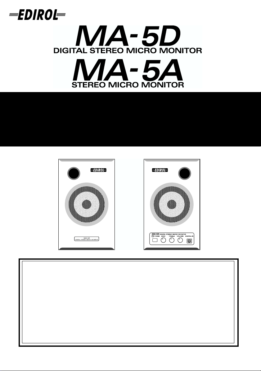
取扱説明書 /
Owner's Manual
Bedienungsanleitung / Mode d’emploi
Manuale d’uso / Manual del usuario
この機器を正しくお使いいただくために、ご使用前に「安全上のご注意」(P.2、3)と「使用上のご注意」
(P.4)をよくお読みください。また、この機器の優れた機能を十分ご理解いただくためにも、取扱説明書
をよくお読みください。取扱説明書は必要なときにすぐに見ることができるよう、手元に置いてください。
2002 ローランド株式会社
©
本書の一部、もしくは全部を無断で複写・転載することを禁じます。
Before using this unit, carefully read the sections entitled: “USING THE UNIT SAFELY” and “IMPORTANT
NOTES” (pp. 9--11). These sections provide important information concerning the proper operation of the
unit. Additionally, in order to feel assured that you have gained a good grasp of every feature provided by
your new unit, Owner’s manual should be read in its entirety. The manual should be saved and kept on hand
as a convenient reference.
Copyright © 2002 ROLAND CORPORATION
All rights reserved. No part of this publication may be reproduced in any form without the written
permission of ROLAND CORPORATION.
02902734 1*KG
安全上のご注意
安全上のご注意
火災・感電・傷害を防止するには
注意の意味について警告と
取扱いを誤った場合に、使用者が
警告
注意
死亡または重傷を負う可能性が想
定される内容を表わしています。
取扱いを誤った場合に、使用者が
傷害を負う危険が想定される場合
および物的損害のみの発生が想定
される内容を表わしています。
※物的損害とは、家屋・家財およ
び家畜・ペットにかかわる拡大
損害を表わしています。
以下の指示を必ず守ってください
警告 警告
001
● この機器を使用する前に、以下の指示
と取扱説明書をよく読んでください。
......................................................................................................
002c
● この機器および AC アダプターを分解
したり、改造したりしないでください。
......................................................................................................
003
● 修理/部品の交換などで、取扱説明書
に書かれていないことは、絶対にしな
いでください。必ずお買い上げ店また
はローランド・サービスに相談してく
ださい。
......................................................................................................
004
● 次のような場所での使用や保存はし
ないでください。
○温度が極端に高い場所(直射日光の
当たる場所、暖房機器の近く、発熱
する機器の上など)
○水気の近く(風呂場、洗面台、濡れ
た床など)や湿度の高い場所
○雨に濡れる場所
○ホコリの多い場所
○振動の多い場所
図記号の例
は、注意(危険、警告を含む)を表わしていま
す。
具体的な注意内容は、 の中に描かれています。
左図の場合は、「一般的な注意、警告、危険」を
表わしています。
は、禁止(してはいけないこと)を表わしてい
ます。
具体的な禁止内容は、 の中に描かれています。
左図の場合は、「分解禁止」を表わしています。
●
は、強制(必ずすること)を表わしています。
具体的な強制内容は、●の中に描かれています。
左図の場合は、「電源プラグをコンセントから抜
くこと」を表わしています。
007
●この機器を、ぐらついた台の上や傾い
た場所に設置しないでください。必ず
安定した水平な場所に設置してくださ
い。
.....................................................................................................
008c
●AC アダプターは、必ず付属のものを、
AC 100V の電源で使用してください。
.....................................................................................................
010
●この機器を単独で、あるいはヘッドホ
ン、アンプ、スピーカーと組み合わせ
て使用した場合、設定によっては永久
的 な難聴になる程度の音量になりま
す。大音量で、長時間使用しないでく
ださい。万一、聴力低下や耳鳴りを感
じたら、直ちに使用をやめて専門の医
師に相談してください。
.....................................................................................................
011
●この機器に、異物(燃えやすいもの、
硬貨、針金など)や液体(水、ジュー
スなど)を絶対に入れないでください。
2
警告
012b
● 次のような場合は、直ちに電源を切っ
て AC アダプターをコンセントから外
し、お買い上げ店またはローランド・
サービスに修理を依頼してください。
○AC アダプター本体、電源コード、
またはプラグが破損したとき
○異物が内部に入ったり、液体がこぼ
れたりしたとき
○機器が(雨などで)濡れたとき
○機器に異常や故障が生じたとき
......................................................................................................
012d
● 次のような場合は、直ちに電源を切っ
て、お買い上げ店またはローランド・
サービスに修理を依頼してください。
○異物が内部に入ったり、液体がこぼ
れたりしたとき
○機器が(雨などで)濡れたとき
○機器に異常や故障が生じたとき
......................................................................................................
013
● お子様のいるご家庭で使用する場合、
お子様の取り扱いやいたずらに注意し
てください。必ず大人のかたが、監視
/指導してあげてください。
......................................................................................................
014
● この機器を落としたり、この機器に強
い衝撃を与えないでください。
......................................................................................................
注意
102c
●AC アダプターを機器本体やコンセン
トに抜き差しするときは、必ずプラグ
を持ってください。
.....................................................................................................
104
●接続したコードやケーブル類は、繁雑
にならないように配慮してください。
特に、コードやケーブル類は、お子様
の手が届かないように配慮してくださ
い。
.....................................................................................................
106
●この機器の上に乗ったり、機器の上に
重いものを置かないでください。
.....................................................................................................
107c
●濡れた手で AC アダプターのプラグを
持って、機器本体やコンセントに抜き
差ししないでください。
.....................................................................................................
108b
●この機器を移動するときは、AC アダプ
ターをコンセントから外し、外部機器
との接続を外してください。
.....................................................................................................
108c
●この機器を移動するときは、外部機器
との接続を外してください。
.....................................................................................................
118
●光デジタル・コネクターのキャップを
外した場合は、小さなお子様が誤って
飲み込んだりすることのないようお子
様の手の届かないところへ保管してく
ださい。
.....................................................................................................
3
使用上のご注意
291a
2〜 3 ペ ージに記載されている「安全上のご注意」以外に、次のことに注意してください。
電源について
307
● 接続するときは、誤動作やスピーカーなどの破損
を防ぐため、必ずすべての機器の電源を切ってく
ださい。
設置について
351
● この機器の近くにパワー・アンプなどの大型トラ
ンスを持つ機器があると、ハム(うなり)を誘導
することがあります。この場合は、この機器との
間隔や方向を変えてください。
352a
● テレビやラジオの近くでこの機器を動作させる
と、テレビ画面に色ムラが出たり、ラジオから雑
音が出ることがあります。この場合は、この機器
を遠ざけて使用してください。
352b
● 携帯電話などの無線機器を本機の近くで使用す
ると、着信時や発信時、通話時に本機から雑音が
出ることがあります。この場合は、それらの機器
を本機から遠ざけるか、もしくは電源を切ってく
ださい。
354a
● 直射日光の当たる場所や、発熱する機器の近く、
閉め切った車内などに放置しないでください。変
形、変色することがあります。
355
● 故障の原因になりますので、雨や水に濡れる場所
で使用しないでください。
お手入れについて
401a
● 通常のお手入れは、柔らかい布で乾拭きするか、
堅く絞った布で汚れを拭き取ってください。汚れ
が激しいときは、中性洗剤を含んだ布で汚れを拭
き取ってから、柔らかい布で乾拭きしてくださ
い。
402
● 変色や変形の原因となるベンジン、シンナーおよ
びアルコール類は、使用しないでください。
修理について
451c(国内のみ)
●お客様がこの機器や AC アダプターを分解、改造
された場合、以後の性能について保証できなくな
ります。また、修理をお断りする場合もあります。
453
●当社では、この製品の補修用性能部品(製品の機
能を維持するために必要な部品)を、製造打切後
6 年間保有しています。この部品保有期間を修理
可能の期間とさせていただきます。なお、保有期
間が経過した後も、故障箇所によっては修理可能
の場合がありますので、お買い上げ店、または最
寄りのローランド・サービスにご相談ください。
その他の注意について
553
●故障の原因になりますので、ボタン、つまみ、入
出力端子などに過度の力を加えないでください。
556
●ケーブルの抜き差しは、ショートや断線を防ぐた
め、プラグを持ってください。
558b
●音楽をお楽しみになる場合、隣近所に迷惑がかか
らないように、特に夜間は、音量に十分注意して
ください。
559a
●輸送や引っ越しをするときは、この機器が入って
いたダンボール箱と緩衝材、または同等品で梱包
してください。
追加
●持ち運びなどの際
に、図のバスレフ・
ポートに指を入れ
ないでください。
指が抜けなくなる
恐れがあります。
562
●接続には、当社ケーブル(PCS シリーズなど)を
ご使用ください。他社製の接続ケーブルをご使用
になる場合は、次の点にご注意ください。
○ 接続ケーブルには抵抗が入ったものがありま
す。本機との接続には、抵抗入りのケーブル
を使用しないでください。音が極端に小さく
なったり、全く聞こえなくなる場合がありま
す。ケーブルの仕様につきましては、ケーブ
ルのメーカーにお問い合わせください。
4
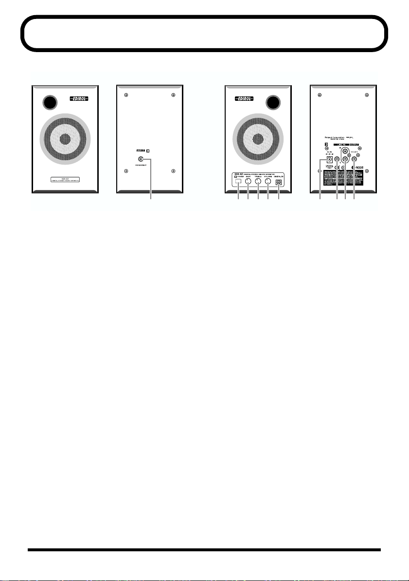
各部の名称とはたらき
fig.2
Left Right
1 2 345A 6 789
1.
L チャンネル・インプット・ジャック
Lチャンネル・アウトプット・ジャックと
接続します。接続には、付属のスピー
カー・ケーブルをご使用ください。
2.
電源スイッチ
パワー/スタンバイ・インジケーター
パワー/スタンバイ・インジケーターは、
スタンバイ状態で赤、電源オンで緑に点灯
します。
9.
L チャンネル・アウトプット・ジャック
L チャンネル・インプット・ジャックと接
続します。
A.
デジタル・インプット・コネクター
(オプティカル)
光デジタル(オプティカル)・ケーブルを接
続するデジタル入力端子です。
MA-5D のみの機能です。
ベースつまみ
3.
低域の音質を調節します。センターでフ
ラットになります。
トレブルつまみ
4.
高域の音質を調節します。センターでフ
ラットになります。
ボリュームつまみ
5.
インプット・ジャックに接続した機器の音
量を調節します。
6.
ACアダプター・ジャック
付属の ACアダプターを接続します。
7.
インプット・ジャック
(ステレオ・ミニ・タイプ)
8.
インプット・ジャック L、R
(RCA ピン・タイプ)
5

接続について
接続および電源投入時のご注意
921
● 他の機器と接続するときは、誤動作やスピーカーなどの破損を防ぐため、必ずすべての機器の音
量を絞った状態で電源を切ってから行ってください。
926â¸
● 抵抗入りの接続ケーブルを使用すると、接続した機器の音量が小さくなることがあります。抵抗
の入っていない接続ケーブルをご使用ください。
941
● 正しく接続したら、必ず次の手順で電源を投入してください。手順を間違えると、誤動作をした
りスピーカーなどが破損する恐れがあります。(電源をオフにするときは、この逆の手順でおこな
います。)
電源を入れる順序..........接続されている機器 → MA-5D/MA-5A
942
● この機器は回路保護のため、電源をオンしてからしばらくは動作しません。
接続例
fig.5j
INPUT
(FROMRIGHT)
OUTPUT
(TOLEFT)
音源、CD/MDプレーヤーなど
MA-5Dのみ
6

主な仕様
デジタル・ステレオ・マイクロ・モニター:MA-5D /ステレオ・マイクロ・モニター:MA-5A
●定格出力
10 W(5W + 5 W)
●スピーカー・ユニット
フルレンジ:7 cm(防磁型)
●再生周波数帯域
70 Hz 〜 20 kHz
●規定入力レベル
ライン:-10 dBu、ステレオ:-10 dBu
●入力インピーダンス
18 kΩ
●コントロール(R チャンネル)
ベースつまみ、トレブルつまみ、
ボリュームつまみ、電源スイッチ
●インジケーター
パワー・インジケーター
●接続端子
Rチャンネル
【フロント(MA-5D のみ)】
デジタル・インプット・コネクター
(オプティカル)
【リア】
インプット・ジャック
(ステレオ・ミニ・タイプ)
インプット・ジャック L、R
(RCAピン・タイプ)
Lチャンネル・アウトプット・ジャック
(RCA ピン・タイプ)
ACアダプター・ジャック
L チャンネル
【リア】
Lチャンネル・インプット・ジャック
(RCA ピン・タイプ)
●エンクロージャー形式
フルレンジ・バスレフ型
●電源
DC 18 V(AC アダプター)
●消費電流
500 mA
●外形寸法
120(幅)×143(奥行)× 194(高さ)mm
●質量
Rチャンネル:1.03 kg
Lチャンネル:0.72 kg
●付属品
取扱説明書、保証書、ACアダプター、
ステレオ・ミニ <-> RCA ピン変換ケーブル、
RCAピン・スピーカー・ケーブル
※ 0 dBu = 0.775 V rms
※ 製品の仕様および外観は、改良のため予告な
く変更することがあります。
お問い合わせの窓口
商品のお取り扱いに関するお問い合わせは
ローランドDTMホットライン
受付時間:午前10時〜午後5時(土、日曜、祝日および弊社規定の休日を除く)
<電話番号>
■大阪 TEL(06)6345-9785 ■東京 TEL(03)3251-5791
<住所>
〒530-0004 大阪市北区堂島浜1-4-16 大和堂島ビル7F
修理に関するお問い合わせは
※上記窓口の名称、所在地、電話番号等は、予告なく変更することがありますのでご了承ください。
商品をお求めの販売店か保証書に同封されている「サービスの窓口」
・・・
に記載の営業所またはサービス・ステーションまでご相談ください。
7
ローランドDTMホットラインまでご相談
・・・
ください。尚、お問い合わせの際には取扱
説明書をご用意ください。
'01.5.1現在(DTM)

Information
When you need repair service, call your nearest EDIROL/Roland Service Center or authorized EDIROL/Roland distributor
in your country as shown below.
AUSTRALIA
EDIROL Australia Pty. Ltd.
72 Central Avenue
Oak Flats NSW 2529
AUSTRALIA
TEL: (02) 4257 9091
http://www.edirol.com.au
EUROPE
EDIROL (Europe) Ltd.
Studio 3.4 114 Power Road
London W4 5PY
U. K.
TEL: +44 (0)20 8747 5949
FAX:+44 (0)20 8747 5948
http://www.edirol.com/europe
Deutschland
TEL: 0700 33 47 65 20
France
TEL: 0810 000 371
Italia
TEL: 02 93778329
U. S. A. / CANADA
EDIROL Corporation North
America
425 Sequoia Drive, Suite 114
Bellingham, WA 98226
U. S. A.
TEL: (360) 594-4276
FAX: (360) 594-4271
http://www.edirol.com/
AFRICAAFRICA
EGYPT
Al Fanny Trading Office
9, EBN Hagar A1 Askalany Street,
ARD E1 Golf, Heliopolis,
Cairo 11341, EGYPT
TEL: 20-2-417-1828
REUNION
Maison FO - YAM Marcel
25 Rue Jules Hermann,
Chaudron - BP79 97 491
Ste Clotilde Cedex,
REUNION ISLAND
TEL: (0262) 218-429
SOUTH AFRICA
That Other Music Shop
(PTY) Ltd.
11 Melle St., Braamfontein,
Johannesbourg, SOUTH AFRICA
P.O.Box 32918, Braamfontein 2017
Johannesbourg, SOUTH AFRICA
TEL: (011) 403 4105
Paul Bothner (PTY) Ltd.
17 Werdmuller Centre,
Main Road, Claremont 7708
SOUTH AFRICA
P.O.BOX 23032, Claremont 7735,
SOUTH AFRICA
TEL: (021) 674 4030
ASIA
CHINA
Beijing Xinghai Musical
Instruments Co., Ltd.
6 Huangmuchang Chao Yang
District, Beijing, CHINA
TEL: (010) 6774 7491
Shanghai Xingtong Acoustics
Equipment CO.,Ltd.
5F. No.1500 Pingliang Road
New East Club Plaza, Shanghai,
CHINA
TEL: (021) 5580-0800
HONG KONG
Tom Lee Music Co., Ltd.
Service Division
22-32 Pun Shan Street, Tsuen
Wan, New Territories,
HONG KONG
TEL: 2415 0911
INDIA
Rivera Digitec (India) Pvt. Ltd.
409, Nirman Kendra Mahalaxmi
Flats Compound Off. Dr. Edwin
Moses Road, Mumbai-400011,
INDIA
TEL: (022) 498 3079
INDONESIA
PT Citra IntiRama
J1. Cideng Timur No. 15J-150
Jakarta Pusat
INDONESIA
TEL: (021) 6324170
KOREA
Cosmos Corporation
1461-9, Seocho-Dong,
Seocho Ku, Seoul, KOREA
TEL: (02) 3486-8855
MALAYSIA
BENTLEY MUSIC SDN BHD
140 & 142, Jalan Bukit Bintang
55100 Kuala Lumpur,MALAYSIA
TEL: (03) 2144-3333
PHILIPPINES
G.A. Yupangco & Co. Inc.
339 Gil J. Puyat Avenue
Makati, Metro Manila 1200,
PHILIPPINES
TEL: (02) 899 9801
SINGAPORE
CRISTOFORI MUSIC PTE
LTD
Blk 3014, Bedok Industrial Park E,
#02-2148, SINGAPORE 489980
TEL: 243 9555
TAIWAN
ROLAND TAIWAN
ENTERPRISE CO., LTD.
Room 5, 9fl. No. 112 Chung Shan
N.Road Sec.2, Taipei, TAIWAN,
R.O.C.
TEL: (02) 2561 3339
THAILAND
Theera Music Co. , Ltd.
330 Verng NakornKasem, Soi 2,
Bangkok 10100, THAILAND
TEL: (02) 2248821
VIETNAM
Saigon Music
138 Tran Quang Khai St.,
District 1
Ho Chi Minh City
VIETNAM
TEL: (08) 844-4068
AUSTRALIA/
NEW ZEALAND
NEW ZEALAND
Roland Corporation Ltd.
32 Shaddock Street, Mount Eden,
Auckland, NEW ZEALAND
TEL: (09) 3098 715
CENTRAL/LATIN
AMERICA
ARGENTINA
Instrumentos Musicales S.A.
Av.Santa Fe 2055
(1123) Buenos Aires
ARGENTINA
TEL: (011) 4508-2700
BRAZIL
Roland Brasil Ltda
Rua San Jose, 780 Sala B
Parque Industrial San Jose
Cotia - Sao Paulo - SP, BRAZIL
TEL: (011) 4615 5666
CHILE
Comercial Fancy II S.A.
Rut.: 96.919.420-1
Nataniel Cox #739, 4th Floor
Santiago - Centro, CHILE
TEL: (02) 688-9540
MEXICO
Casa Veerkamp, s.a. de c.v.
Av. Toluca No. 323, Col. Olivar
de los Padres 01780 Mexico D.F.
MEXICO
TEL: 668-0480
PERU
VIDEO Broadcast S.A.
Portinari 199 (ESQ. HALS)
San Borja, Lima 41
REP. OF PERU
TEL: (01) 4758226
URUGUAY
Todo Musica S.A.
Francisco Acuna de Figueroa 1771
C.P.: 11.800
Montevideo, URUGUAY
TEL: (02) 924-2335
VENEZUELA
Musicland Digital C.A.
Av. Francisco de Miranda,
Centro Parque de Cristal, Nivel
C2 Local 20 Caracas
VENEZUELA
TEL: (212) 285-8586
EUROPE
AUSTRIA
Roland Austria GES.M.B.H.
Siemensstrasse 4, P.O. Box 74,
A-6063 RUM, AUSTRIA
TEL: (0512) 26 44 260
BELGIUM/HOLLAND/
LUXEMBOURG
Roland Benelux N. V.
Houtstraat 3, B-2260, Oevel
(Westerlo) BELGIUM
TEL: (014) 575811
DENMARK
Roland Scandinavia A/S
Nordhavnsvej 7, Postbox 880,
DK-2100 Copenhagen
DENMARK
TEL: (039)16 6200
FRANCE
Roland France SA
4, Rue Paul Henri SPAAK,
Parc de l'Esplanade, F 77 462 St.
Thibault, Lagny Cedex FRANCE
TEL: 01 600 73 500
FINLAND
Roland Scandinavia As,
Filial Finland
Lauttasaarentie 54 B
Fin-00201 Helsinki, FINLAND
TEL: (9) 682 4020
GERMANY
Roland Elektronische
Musikinstrumente HmbH.
Oststrasse 96, 22844 Norderstedt,
GERMANY
TEL: (040) 52 60090
GREECE
STOLLAS S.A.
Music Sound Light
155, New National Road
Patras 26442, GREECE
TEL: (061) 43-5400
HUNGARY
Intermusica Ltd.
Warehouse Area ‘DEPO’ Pf.83
H-2046 Torokbalint, HUNGARY
TEL: (23) 511011
IRELAND
Roland Ireland
Audio House, Belmont Court,
Donnybrook, Dublin 4.
Republic of IRELAND
TEL: (01) 2603501
ITALY
Roland Italy S. p. A.
Viale delle Industrie 8,
20020 Arese, Milano, ITALY
TEL: (02) 937-78300
NORWAY
Roland Scandinavia Avd.
Kontor Norge
Lilleakerveien 2 Postboks 95
Lilleaker N-0216 Oslo
NORWAY
TEL: 273 0074
POLAND
P. P. H. Brzostowicz
UL. Gibraltarska 4.
PL-03664 Warszawa POLAND
TEL: (022) 679 44 19
PORTUGAL
Tecnologias Musica e Audio,
Roland Portugal, S.A.
Cais Das Pedras, 8/9-1 Dto
4050-465 PORTO
PORTUGAL
TEL: (022) 608 00 60
ROMANIA
FBS LINES
Piata Libertatii 1,
RO-4200 Gheorgheni
TEL: (066) 164-609
RUSSIA
MuTek
3-Bogatyrskaya Str. 1.k.l
107 564 Moscow, RUSSIA
TEL: (095) 169 5043
SPAIN
Roland Electronics
de España, S. A.
Calle Bolivia 239, 08020
Barcelona, SPAIN
TEL: (93) 308 1000
SWEDEN
Roland Scandinavia A/S
SWEDISH SALES OFFICE
Danvik Center 28, 2 tr.
S-131 30 Nacka SWEDEN
TEL: (08) 702 0020
SWITZERLAND
Roland (Switzerland) AG
Musitronic AG
Gerberstrasse 5, Postfach,
CH-4410 Liestal, SWITZERLAND
TEL: (061) 927-8383
UKRAINE
TIC-TAC
Mira Str. 19/108
P.O. Box 180
295400 Munkachevo, UKRAINE
TEL: (03131) 414-40
UNITED KINGDOM
Roland (U.K.) Ltd.
Atlantic Close, Swansea
Enterprise Park, SWANSEA
SA7 9FJ,
UNITED KINGDOM
TEL: (01792) 700139
MIDDLE EAST
BAHRAIN
Moon Stores
No.16, Bab Al Bahrain Avenue,
P.O.Box 247, Manama 304,
State of BAHRAIN
TEL: 211 005
CYPRUS
Radex Sound Equipment Ltd.
17, Diagorou Street, Nicosia,
CYPRUS
TEL: (02) 66-9426
IRAN
MOCO, INC.
No.41 Nike St., Dr.Shariyati Ave.,
Roberoye Cerahe Mirdamad
Tehran, IRAN
TEL: (021) 285-4169
ISRAEL
Halilit P. Greenspoon &
Sons Ltd.
8 Retzif Ha’aliya Hashnya St.
Tel-Aviv-Yafo ISRAEL
TEL: (03) 6823666
JORDAN
AMMAN Trading Agency
245 Prince Mohammad St.,
Amman 1118, JORDAN
TEL: (06) 464-1200
KUWAIT
Easa Husain Al-Yousifi
Abdullah Salem Street,
Safat, KUWAIT
TEL: 243-6399
LEBANON
A. Chahine & Fils
Gerge Zeidan St., Chahine Bldg.,
Achrafieh, P.O.Box: 16-5857
Beirut, LEBANON
TEL: (01) 20-1441
QATAR
Badie Studio & Stores
P.O. Box 62,
Doha, QATAR
TEL: 423554
SAUDI ARABIA
aDawliah Universal
Electronics APL
Corniche Road, Aldossary Bldg.,
1st Floor, Alkhobar,
SAUDI ARABIA
P.O.Box 2154, Alkhobar 31952
SAUDI ARABIA
TEL: (03) 898 2081
SYRIA
Technical Light & Sound
Center
Bldg. No. 47,
Khaled Ebn Al Walid St.
Damascus, SYRIA
TEL: (011) 221-1230
TURKEY
Barkat Muzik aletleri ithalat
ve ihracat Ltd Sti
Siraselviler Caddesi Siraselviler
Pasaji No:74/20
Taksim - Istanbul, TURKEY
TEL: (0212) 2499324
U.A.E.
Zak Electronics & Musical
Instruments Co. L.L.C.
Zabeel Road, Al Sherooq Bldg.,
No. 14, Grand Floor, Dubai, U.A.E.
TEL: (04) 3360715
As of January 1, 2002 (EDIROL-1)

USING THE UNIT SAFELY
Used for instructions intended to alert
the user to the risk of death or severe
injury should the unit be used
improperly.
Used for instructions intended to alert
the user to the risk of injury or material
damage should the unit be used
improperly.
* Material damage refers to damage or
other adverse effects caused with
respect to the home and all its
furnishings, as well to domestic
animals or pets.
001
• Before using this unit, make sure to
read the instructions below, and the
Owner’s Manual.
..................................................................................................
002c
• Do not open (or modify in any way)
the unit or its AC adaptor.
..................................................................................................
003
• Do not attempt to repair the unit, or
replace parts within it (except when
this manual provides specific instructions directing you to do so). Refer all
servicing to your retailer, the nearest
Roland Service Center, or an authorized Roland distributor, as listed on
the "Information" page.
..................................................................................................
004
• Never use or store the unit in places
that are:
• Subject to temperature extremes
(e.g., direct sunlight in an enclosed
vehicle, near a heating duct, on top
of heat-generating equipment); or
are
• Damp (e.g., baths, washrooms, on
wet floors); or are
• Humid; or are
• Exposed to rain; or are
• Dusty; or are
• Subject to high levels of vibration.
The symbol alerts the user to important instructions
or warnings.The specific meaning of the symbol is
determined by the design contained within the
triangle. In the case of the symbol at left, it is used for
general cautions, warnings, or alerts to danger.
The symbol alerts the user to items that must never
be carried out (are forbidden). The specific thing that
must not be done is indicated by the design contained
within the circle. In the case of the symbol at left, it
means that the unit must never be disassembled.
The ● symbol alerts the user to things that must be
carried out. The specific thing that must be done is
indicated by the design contained within the circle. In
the case of the symbol at left, it means that the powercord plug must be unplugged from the outlet.
007
• Make sure you always have the unit
placed so it is level and sure to remain
stable. Never place it on stands that
could wobble, or on inclined surfaces.
..................................................................................................
008c
• Be sure to use only the AC adaptor
supplied with the unit. Also, make
sure the line voltage at the installation
matches the input voltage specified on
the AC adaptor’s body. Other AC
adaptors may use a different polarity,
or be designed for a different voltage,
so their use could result in damage,
malfunction, or electric shock.
..................................................................................................
010
• This unit, either alone or in combination with an amplifier and
headphones or speakers, may be
capable of producing sound levels that
could cause permanent hearing loss.
Do not operate for a long period of
time at a high volume level, or at a
level that is uncomfortable. If you
experience any hearing loss or ringing
in the ears, you should immediately
stop using the unit, and consult an
audiologist.
9

011
• Do not allow any objects (e.g.,
flammable material, coins, pins); or
liquids of any kind (water, soft drinks,
etc.) to penetrate the unit.
..................................................................................................
012b
• Immediately turn the power off,
remove the AC adaptor from the
outlet, and request servicing by your
retailer, the nearest Roland Service
Center, or an authorized Roland
distributor, as listed on the "Information" page when:
• The AC adaptor, the power-supply
cord, or the plug has been
damaged; or
• Objects have fallen into, or liquid
has been spilled onto the unit; or
• The unit has been exposed to rain
(or otherwise has become wet); or
• The unit does not appear to operate
normally or exhibits a marked
change in performance.
..................................................................................................
012d
• Immediately turn the power off, and
request servicing by your retailer, the
nearest Roland Service Center, or an
authorized Roland distributor, as
listed on the "Information" page when:
• Objects have fallen into, or liquid
has been spilled onto the unit; or
• The unit has been exposed to rain
(or otherwise has become wet); or
• The unit does not appear to operate
normally or exhibits a marked
change in performance.
..................................................................................................
013
• In households with small children, an
adult should provide supervision until
the child is capable of following all the
rules essential for the safe operation of
the unit.
..................................................................................................
014
• Protect the unit from strong impact.
(Do not drop it!)
102c
• Always grasp only the plug on the AC
adaptor cord when plugging into, or
unplugging from, an outlet or this unit.
..................................................................................................
104
• Try to prevent cords and cables from
becoming entangled. Also, all cords
and cables should be placed so they
are out of the reach of children.
..................................................................................................
106
• Never climb on top of, nor place heavy
objects on the unit.
..................................................................................................
107c
• Never handle the AC adaptor or its
plugs with wet hands when plugging
into, or unplugging from, an outlet or
this unit.
..................................................................................................
108b
• Before moving the unit, disconnect the
AC adaptor and all cords coming from
external devices.
..................................................................................................
108c
• Disconnect all cords coming from
external devices before moving the
unit.
..................................................................................................
118
• Should you remove the optical
connector caps, make sure to put them
in a safe place out of children's reach,
so there is no chance of them being
swallowed accidentally.
10

IMPORTANT NOTES
291a
In addition to the items listed under “USING THE UNIT SAFELY” on page 9--10, please read and
observe the following:
Power Supply
307
• Before connecting this unit to other devices,
turn off the power to all units. This will help
prevent malfunctions and/or damage to
speakers or other devices.
Placement
351
• Using the unit near power amplifiers (or
other equipment containing large power
transformers) may induce hum. To alleviate
the problem, change the orientation of this
unit; or move it farther away from the source
of interference.
352a
• This device may interfere with radio and
television reception. Do not use this device in
the vicinity of such receivers.
352b
• Noise may be produced if wireless communications devices, such as cell phones, are
operated in the vicinity of this unit. Such
noise could occur when receiving or initiating
a call, or while conversing. Should you
experience such problems, you should
relocate such wireless devices so they are at a
greater distance from this unit, or switch
them off.
354a
• Do not expose the unit to direct sunlight,
place it near devices that radiate heat, leave it
inside an enclosed vehicle, or otherwise
subject it to temperature extremes. Excessive
heat can deform or discolor the unit.
355
• To avoid possible breakdown, do not use the
unit in a wet area, such as an area exposed to
rain or other moisture.
Maintenance
401a
• For everyday cleaning wipe the unit with a
soft, dry cloth or one that has been slightly
dampened with water. To remove stubborn
dirt, use a cloth impregnated with a mild,
non-abrasive detergent. Afterwards, be sure
to wipe the unit thoroughly with a soft, dry
cloth.
402
• Never use benzine, thinners, alcohol or
solvents of any kind, to avoid the possibility
of discoloration and/or deformation.
Additional Precautions
553
• Use a reasonable amount of care when using
the unit’s buttons, sliders, or other controls;
and when using its jacks and connectors.
Rough handling can lead to malfunctions.
556
• When connecting / disconnecting all cables,
grasp the connector itself—never pull on the
cable. This way you will avoid causing shorts,
or damage to the cable’s internal elements.
558b
• To avoid disturbing your neighbors, try to
keep the unit’s volume at reasonable levels
(especially when it is late at night).
559a
• When you need to transport the unit, package
it in the box (including padding) that it came
in, if possible. Otherwise, you will need to use
equivalent packaging materials.
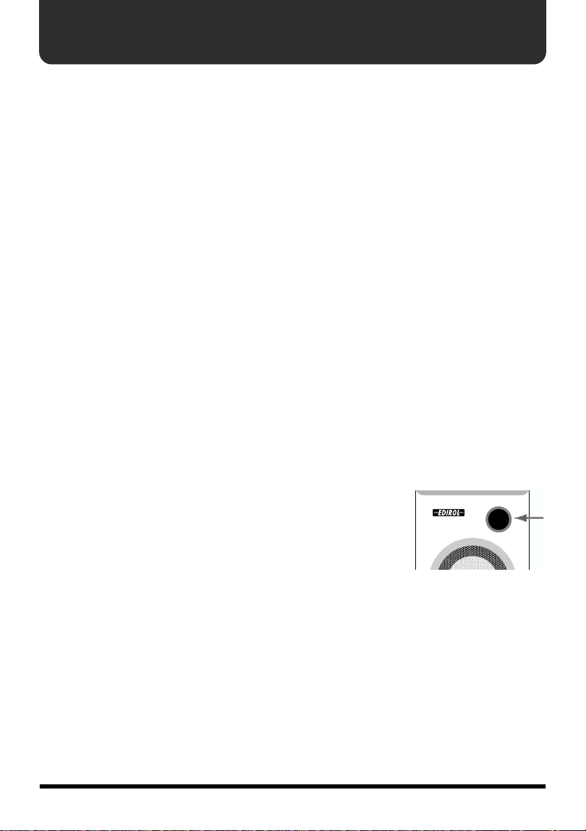
Add
• Be sure to avoid
inserting your
fingers in the
bass reflex ports
when transporting or
moving the
speakers, as your fingers may become
wedged and stuck in the ports.
562
• Use a cable from Roland to make the
connection. If using some other make of
connection cable, please note the following
precautions.
• Some connection cables contain resistors.
Do not use cables that incorporate resistors
for connecting to this unit. The use of such
cables can cause the sound level to be
extremely low, or impossible to hear. For
information on cable specifications, contact
the manufacturer of the cable.
11

IMPORTANT: THE WIRES IN THIS MAINS LEAD ARE COLOURED IN ACCORDANCE WITH THE FOLLOWING CODE.
BLUE:
BROWN:
As the colours of the wires in the mains lead of this apparatus may not correspond with the coloured markings identifying
the terminals in your plug, proceed as follows:
The wire which is coloured BLUE must be connected to the terminal which is marked with the letter N or coloured BLACK.
The wire which is coloured BROWN must be connected to the terminal which is marked with the letter L or coloured RED.
Under no circumstances must either of the above wires be connected to the earth terminal of a three pin plug.
This product complies with the requirements of European Directive 89/336/EEC.
NEUTRAL
LIVE
For the U.K.
For EU Countries
For the USA
FEDERAL COMMUNICATIONS COMMISSION
RADIO FREQUENCY INTERFERENCE STATEMENT
This equipment has been tested and found to comply with the limits for a Class B digital device, pursuant to Part 15 of the
FCC Rules. These limits are designed to provide reasonable protection against harmful interference in a residential
installation. This equipment generates, uses, and can radiate radio frequency energy and, if not installed and used in
accordance with the instructions, may cause harmful interference to radio communications. However, there is no guarantee
that interference will not occur in a particular installation. If this equipment does cause harmful interference to radio or
television reception, which can be determined by turning the equipment off and on, the user is encouraged to try to correct the
interference by one or more of the following measures:
– Reorient or relocate the receiving antenna.
– Increase the separation between the equipment and receiver.
– Connect the equipment into an outlet on a circuit different from that to which the receiver is connected.
– Consult the dealer or an experienced radio/TV technician for help.
This device complies with Part 15 of the FCC Rules. Operation is subject to the following two conditions:
(1) This device may not cause harmful interference, and
(2) This device must accept any interference received, including interference that may cause undesired operation.
Unauthorized changes or modification to this system can void the users authority to operate this equipment.
This equipment requires shielded interface cables in order to meet FCC class B Limit.
For Canada
NOTICE
This Class B digital apparatus meets all requirements of the Canadian Interference-Causing Equipment Regulations.
AVIS
Cet appareil numérique de la classe B respecte toutes les exigences du Règlement sur le matériel brouilleur du Canada.
12

Panel Description
fig.2
Left Right
1 2 345A 6 789
1.
L Channel Input Jack
Connect this to L Channel Output Jack on the
right-side unit. For the connection, use the
included speaker cable.
2.
POWER Switch, POWER/STANDBY Indicator
The POWER/STANDBY Indicator lights up
in red during standby, and lights up in green
when power is on.
3.
BASS Control Knob
4.
TREBLE Control Knob
These adjust the tones of the bass and treble.
Set to center to make the tones flat.
5.
VOLUME Knob
Adjusts the volume of devices connected to
Input Jacks.
6. AC Adaptor Jack
Connect the included AC adaptor to this jack.
7. Input Jack (stereo mini type)
8. Input Jacks L, R (RCA pin type)
9. L Channel Output Jack
Connect this to L Channel Input Jack on the
left-side unit.
MA-5D only
A. Digital Input Connector (Optical)
This is the digital input connector for opticfiber cable.
Bedienfeldbeschreibung.......Deutsch
1. L-Kanal-Eingangsbuchse
Verbinden Sie diese Buchse mit der L-KanalAusgangsbuchse der Einheit auf der rechten
Seite. Verwenden Sie für den Anschluss das
beiliegende Lautsprecherkabel.
2. POWER-Schalter, POWER/STANDBY-
Anzeige
Die POWER/STANDBY-Anzeige leuchtet im
Standby-Betrieb rot. Im Netzbetrieb leuchtet
diese Anzeige grün.
3. BASS-Drehknopf
4. TREBLE-Drehknopf
Mit diesen Bedienelementen werden Bass
und Treble reguliert. Drehen Sie die
Drehknöpfe bis zur Mitte, um einen tiefen
Ton zu erzeugen.
5. VOLUME-Drehknopf
Mit diesem Bedienelement wird die
Lautstärke der an die Eingangsbuchsen
angeschlossenen Geräte geregelt.
6. Netzteilanschluß
Schließen Sie das mitgelieferte Netzteil an
diese Buchse.
7. Eingangsbuchse (Stereo Mini)
8. Eingangsbuchsen L, R(RCA-Stift)
9. L-Kanal-Ausgangsbuchse
Verbinden Sie diese Buchse mit der L-KanalEingangsbuchse der Einheit auf der linken
Seite.
MA-5D
A. Anschluss Digitaleingabe (optisch)
Dies ist der Digitaleingabe-Anschluss für
faseroptische Kabel.
13

Panel Description
Description...........................Français
1. Prise d’entrée canal L (G)
Connectez à la prise de sortie du canal L sur
la droite de l’appareil. Pour la connexion,
utilisez le câble pour enceintes inclus.
2. Commutateur POWER, voyant POWER/
STANDBY
Le voyant POWER/STANDBY est rouge en
mode veille, et vert lorsque l’appareil est
alimenté.
3. Bouton BASS
4. Bouton TREBLE
Ils servent à régler les basses et les aiguës.
Pour obtenir un réglage neutre, mettre les
boutons en position médiane.
5. Bouton VOLUME
Sert à ajuster le volume des appareils
connectés aux jacks d'entrée.
6. Jack pour adaptateur AC
Connectez sur ce jack l'adaptateur AC inclus.
7. Prise d’entrée (type mini-stéréo)
8. Prises d’entrée L, R (type RCA)
9. Prise de sortie canal L (G)
Connectez à la prise de sortie du canal L sur
la gauche de l’appareil.
MA-5D
A. Connecteur d’entrée numérique (optique)
Connecteur d’entrée numérique pour câble
en fibre optique.
Descrizione del pannello.......Italiano
1. Presa d’ingresso canale sinistro
Collegare alla presa d’uscita del canale
sinistro sul lato destro dell’apparecchio. Per
effettuare il collegamento, utilizzare il cavo
per altoparlanti in dotazione.
2. Interruttore POWER, Indicatore POWER/
STANDBY
L’indicatore POWER/STANDBY diventa
rosso in standby e verde quando
l’apparecchio è acceso.
3. Manopola BASS
4. Manopola TREBLE
Regolano i bassi e gli acuti. Regolare al centro
per uniformare il suono.
5. Manopola VOLUME
Regola il volume dei dispositivi collegati alle
prese d'ingresso.
6. Ingresso alimentazione
Collegare qui l’alimentatore di corrente.
7. Presa d’ingresso (tipo mini stereo)
8. Prese d’ingresso L, R (pin tipo RCA)
9. Presa d’uscita canale sinistro
Collegare alla presa d’ingresso del canale
sinistro sul lato sinistro dell’apparecchio.
MA-5D
A. Connettore di ingresso digitale (ottico)
Connettore d’ingresso digitale per il cavo a
fibre ottiche.
Descripción del panel......Español
1. Jack de entrada del canal izquierdo
Conéctelo al jack de salida del canal izquierdo
que se encuentra en el lado derecho de la
unidad. Para la conexión, utilice el cable del
altavoz que viene incluido.
2. Interruptor POWER, Indicador POWER/
STANDBY
El indicador POWER/STANDBY muestra
una luz de color rojo cuando la unidad se
encuentra en modo de espera y una luz de
color verde cuando está encendida.
3. Control BASS
4. Control TREBLE
Estos botones ajustan el tono de los bajos y los
agudos. Cóloquelos en el centro para que los
tonos queden nivelados.
5. Perilla de VOLUMEN
Ajusta el volumen de los dispositivos
conectados a los enchufes de entrada.
6. Jack adaptador AC
Conecte el adaptador AC incluído a este jack.
7. Jack de entrada (stereo mini type)
8. Jacks de entrada (Izquierda, Derecha)
(tipo de patilla RCA)
9. Jack de salida del canal izquierdo
Conéctelo al jack de entrada del canal
izquierdo que se encuentra en el lado
izquierdo de la unidad.
MA-5D
A. Conector de entrada digital (Optical)
Este es el conector de entrada digital para el
cable de fibra óptica.
14

Connections
Precautions When Connecting and Turning on the Power
921
• To prevent malfunction and/or damage to speakers or other devices, always turn down the
volume, and turn off the power on all devices before making any connections.
926_fix
• Using a connection cable that contains a resistor can cause the sound level to be low. Use a
connection cable that does not contain a resistor.
941
• Once the connections have been completed, turn on power to your various devices in the order
specified. By turning on devices in the wrong order, you risk causing malfunction and/or damage
to speakers and other devices. (When turning the power off, reverse this procedure.)
The devices must be turned on in this order.
Connected devices ➔ MA-5D/MA-5A
942
• This unit is equipped with a protection circuit. A brief interval (a few seconds) after power up is
required before the unit will operate normally.
Connection Example
fig.5e
INPUT
(FROM RIGHT)
OUTPUT
(TO LEFT)
Sound Module, CD Player, MD Player, etc.
15
MA-5D
only

Specifications
DIGITAL STEREO MICRO MONITOR: MA-5D
STEREO MICRO MONITOR: MA-5A
Rated Power Output
10 W (5 W + 5 W)
Enclosure
Full-range Bass-reflex type
Speaker Unit
Full-range: 7 cm / 2-13/16 inches
(Magnetically-Shielded)
Frequency Range
70 Hz to 20 kHz
Nominal Input Level
Line: -10 dBu
Stereo: -10 dBu
Input Impedance
18 k ohms
Controls
[R Channel]
BASS Control Knob
TREBLE Control Knob
VOLUME Knob
POWER Switch
Indicator
Power Indicator
Connectors
[R Channel]
Front (MA-5D only):
Digital Input Connector (optical)
Power Supply
DC 18 V (AC Adaptor)
Current Draw
500 mA
Dimensions
120 (W) x 143 (D) x 194 (H) mm
4-3/4 (W) x 5-11/16 (D) x 7-11/16 (H) inches
Weight
[R Channel] 1.03 kg / 2 lbs 5 oz
[L Channel] 0.72 kg / 1 lbs 10 oz
Accessories
Owner's Manual
Conversion Cable
(stereo miniature phone type <-> RCA phono
type)
Speaker Cable (RCA phono type)
AC adaptor
Rear:
Input Jack (stereo miniature phone type)
Input Jacks L, R (RCA phono type)
L Channel Output Jack (RCA phono type)
AC Adaptor Jack
[L Channel]
Rear:
L Channel Input Jack (RCA phono type)
* 0 dBu = 0.775 V rms
* In the interest of product improvement, the
specifications and/or appearance of this unit are
subject to change without prior notice.
16
 Loading...