

Page 1
M-380 RCS
User’s Guide
Roland corporation and its affiliates assume no responsibility for any loss or damage (loss of profits,
loss of data or other economical losses) caused by use of this software. This is applicable even in case
users were notified from Roland Corporation and its affiliates about possibility of such losses.
Copyright © 2009 ROLAND CORPORATION
All rights reserved. No part of this publication may be reproduced in any form without the written
permission of ROLAND CORPORATION
Page 2

2
Page 3

Contents
Contents ..........................................................................................................3
Introduction ....................................................................................................4
About M-380 RCS....................................................................................................................................................................... 4
The two modes of M-380 RCS............................................................................................................................................... 5
Operating requirements ......................................................................................................................................................... 6
Installing M-380 RCS................................................................................................................................................................. 6
Uninstalling M-380 RCS........................................................................................................................................................... 6
About the M-400 Driver .......................................................................................................................................................... 6
Connection to the M-380........................................................................................................................................................ 7
Starting and exiting the application.............................................................9
Starting the application .......................................................................................................................................................... 9
Exiting the application............................................................................................................................................................. 9
Names of things and what they do............................................................. 10
M-380 RCS window.................................................................................................................................................................10
Operations in the main screen area.................................................................................................................................. 14
About the menus.....................................................................................................................................................................15
Using M-380 RCS.......................................................................................... 16
Opening and saving a project.............................................................................................................................................16
Switching between modes ..................................................................................................................................................18
REAC input/output settings.................................................................................................................................................21
Initializing the settings ..........................................................................................................................................................23
Preference settings .................................................................................................................................................................24
LCR System settings................................................................................................................................................................26
M-48 settings.............................................................................................................................................................................27
Offline mode ................................................................................................ 28
Operation in offline mode....................................................................................................................................................28
Work flow in offline mode....................................................................................................................................................28
Online mode................................................................................................. 30
Operation in online mode....................................................................................................................................................30
Synchronization in online mode........................................................................................................................................30
Work flow in online mode ....................................................................................................................................................30
Appendix ...................................................................................................... 32
Warning/error messages.......................................................................................................................................................32
Troubleshooting ......................................................................................................................................................................32
3
Page 4
Introduction
About M-380 RCS
M-380 RCS is application software that runs on Microsoft Windows XP, Microsoft
Windows Vista, or Microsoft Windows 7. It lets you edit M-380 project files, and
remotely control the M-380.
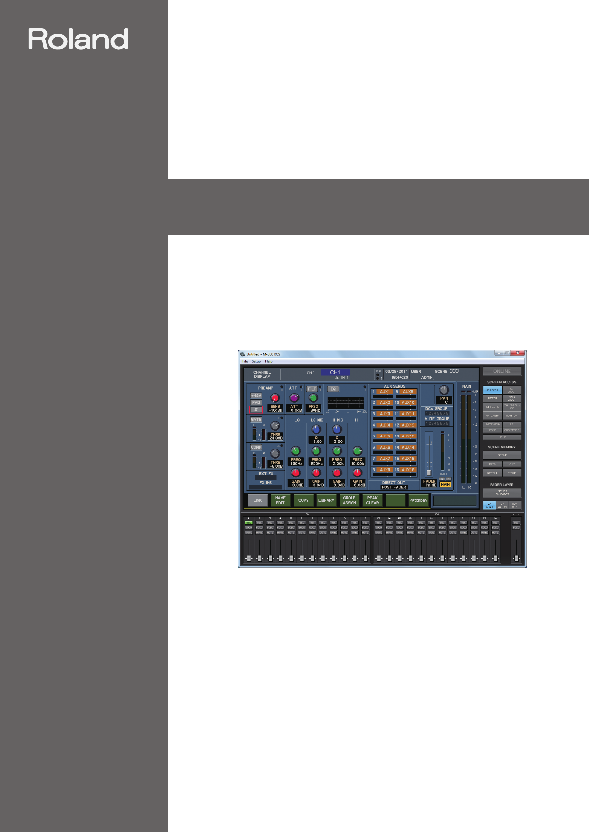
The screen of M-380 RCS is designed to resemble the screen and controllers of the
M-380 itself, and the method of operation is also essentially the same as on the M-
380. This means that the operations you’ve become familiar with on the M-380 can
be used on M-380 RCS, and also that you can use M-380 RCS to familiarize yourself
with operations of the M-380 itself.
fig.ScrRCS.eps
The contents of this document are written with the assumption that the user has all
of the basic knowledge and skills required to operate a Windows computer. Please
read the owner’s manual of your computer if you have questions regarding basic
operations.
4
Page 5
The two modes of M-380 RCS
M-380 RCS has two modes: Offline mode and Online mode.
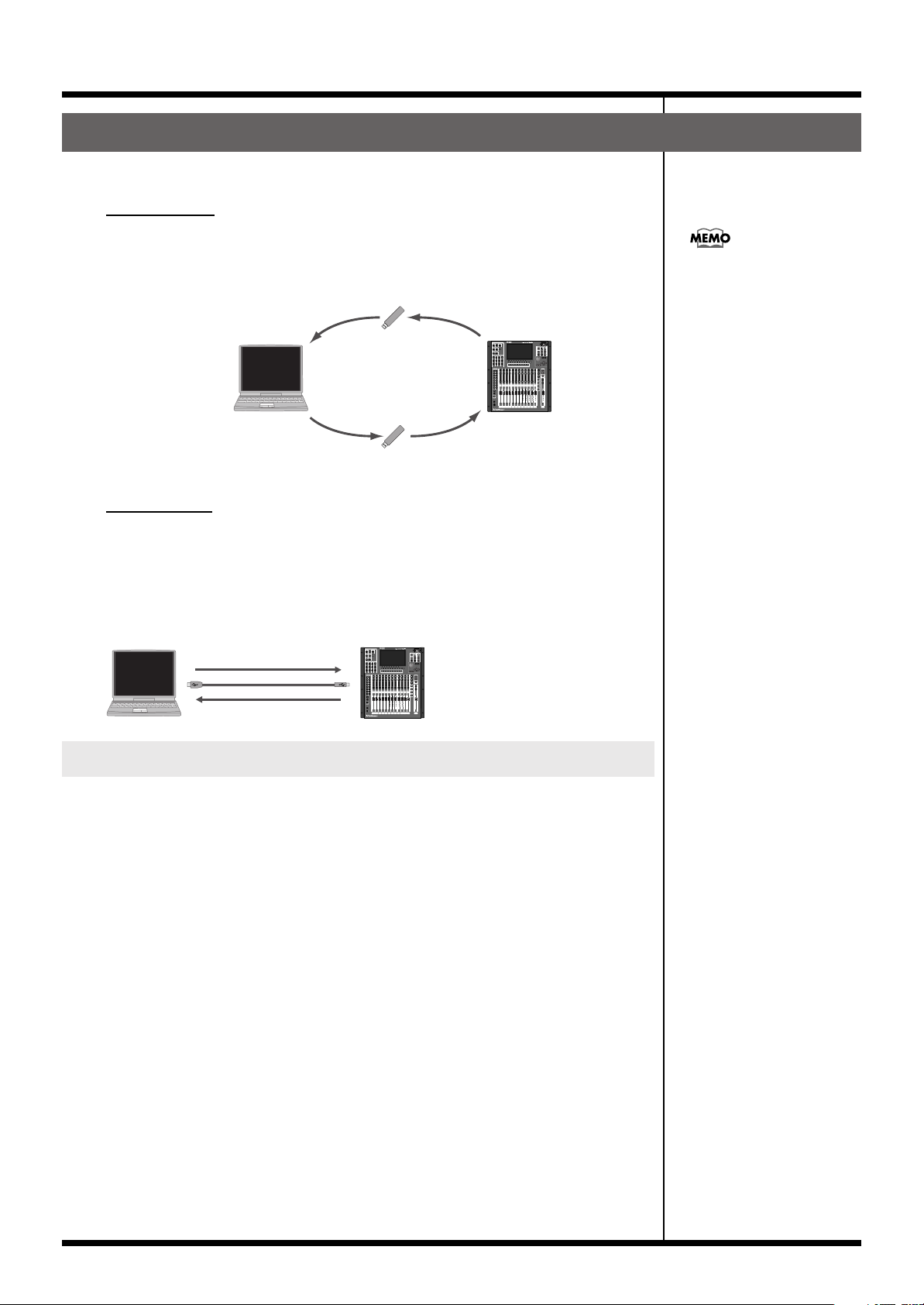
Offline mode
In this mode you can edit an M-380 project file via USB memory. The advantage of
this mode is that you can edit mixer parameters and scene memories even when the
M-380 itself is not at hand.
fig.OfflineEdit.eps
Save the project fileLoad the project file
USB memory
Edit within M-380RCS
Introduction
You can also create a new
project file in M-380 RCS and
load it into the M-380.
USB memory
Load the project fileSave the project file
Online mode
In this mode you can connect your computer to the M-380 via USB, and control the
M-380 remotely. Since M-380 RCS lets you use your mouse and keyboard to control
the M-380, you can operate it in a more intuitive manner. In addition, M-380 RCS can
show a separate screen that is different from the screen shown on the M-380 itself,
letting you view and edit more information simultaneously.
fig.OnlineEdit.eps
Control the M-380
Operations on the M-380 are fed back
Differences from the M-380 itself
M-380 RCS cannot monitor the audio signals within the M-380. Nor can it operate the
following screens, parameters, and buttons.
• SYSTEM screen
• RECORDER screen
• USER screen
• USER FADER layer
• USER button
• MONITOR LEVEL knob setting
• PHONES LEVEL knob setting
• TALKBACK MIC LEVEL knob setting
• [TALKBACK] button
• [SOLO CLEAR] button
The following functionality cannot be used while the M-380 console displays the
analyzer function or the M-48 SOURCE LEVEL/PAN popup.
• The analyzer in the GEQ EDIT popup
• The analyzer in the METER screen Analyzer tab
• The meters of the M-48 SOURCE LEVEL/PAN popup
5
Page 6
Introduction
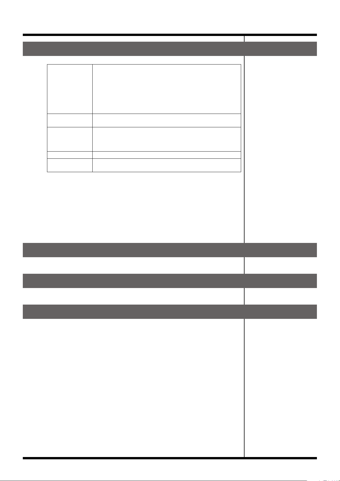
Operating requirements
Supported OS
Supported
computers
CPU/clock Pentium/Celeron or compatible processor, 1.6GHz or faster
Memory 512 MB or more
Screen resolution
and color depth
* This software has been found to work on typical computers that meet the above
requirements, but we do not guarantee that it will operate on all such computers.
Please be aware that differences in design or conditions of use may produce
differences in the processing power of otherwise similar computers.
* You can connect the M-380 to a USB connector that supports USB 2.0. However, even
when connected to a USB 2.0 connector, it will operate only as a USB 1.0/1.1 device.
This will not affect the performance of the M-380 console itself.
Microsoft Windows XP Home Edition/Professional SP 3
Microsoft Windows Vista 32-bit Edition SP 1
Microsoft Windows Vista 64-bit Edition SP 1
Microsoft Windows 7 32-bit Edition
Microsoft Windows 7 64-bit Edition
* M-380 RCS does not work with Microsoft Windows XP Media Center Edition.
A computer that provides a USB connector complying with USB
Specification Revision 1.0 or later USB
* We cannot make guarantees regarding the compatibility of processors.
1024 x 768 pixels or higher, 65,536 colors (16-bit color) or higher
Installing M-380 RCS
Copy the “M-380 RCS” folder to the drive of your computer.
Uninstalling M-380 RCS
Delete the “M-380 RCS” folder that you copied to the drive of your computer.
About the M-400 Driver
In order for M-380 RCS to remotely control the M-380 console, the M-400 Driver for
Windows XP, Windows Vista, or Windows 7 must be installed in your computer.
Download the most recent version of the driver from the following website. For
details on installing the M-400 Driver, refer to the document (HTML file) included
with the driver.
http://www.rolandsystemsgroup.net/
6
Page 7
.
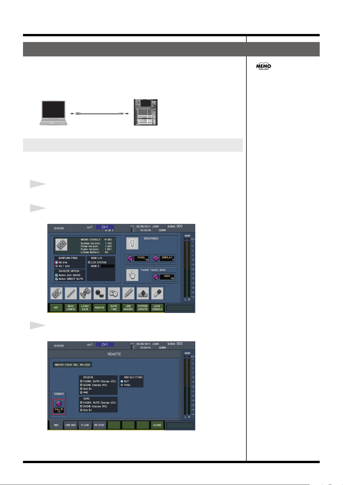
Connection to the M-380
In order to remotely control the M-380 console from M-380 RCS, you’ll need to
connect the M-380 to your computer using a USB cable.
Use a USB cable to connect the M-380 to your computer as shown in the illustration
below.
fig.USBConnection.eps
USB cable
To USB Port
To the rear panel
USB connector
Settings on the M-380 console
In order to remotely control the M-380 from M-380 RCS, make the following settings
on the M-380.
1
Start up the M-380.
Introduction
Use a commercially available
USB cable (one that supports
USB 1.1 or later, and has a
male type A connector and a
male type B connector).
2
Press [SYSTEM] to access the SYSTEM screen.
fig.ScrM4System.eps
3
Press [F4 (REMOTE)] to access the REMOTE popup.
fig.ScrM4SystemRemote.eps
7
Page 8
Introduction
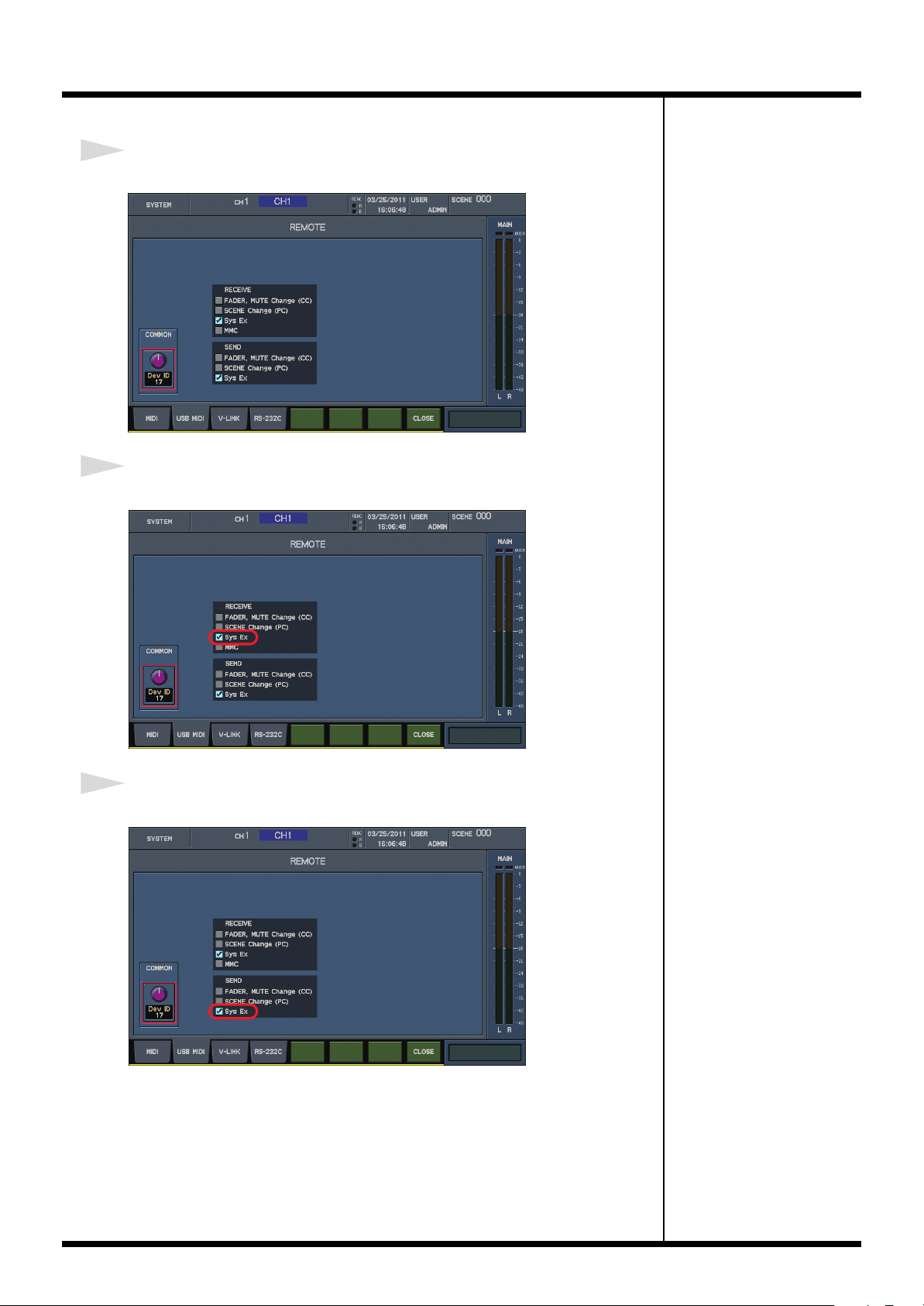
4
Press [F2 (USB MIDI)] to access the USB MIDI tab.
fig.ScrM4SysRemUSB.eps
5
In the RECEIVE section, select the “Sys Ex” button.
fig.ScrM4SysRemUSBSt1.eps
6
In the SEND section, select the “Sys Ex” button.
fig.ScrM4SysRemUSBSt2.eps
8
Page 9
Starting and exiting the application
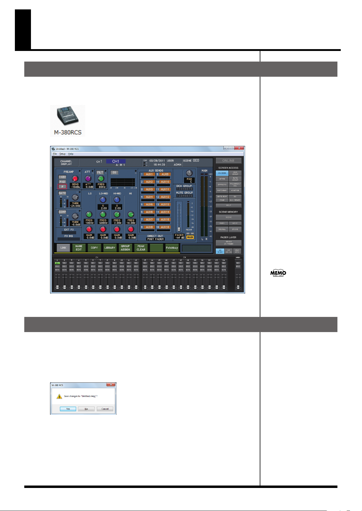
Starting the application
1
In the “M-380 RCS” folder, double-click “M-380 RCS.exe”.
fig.IconRCS.eps
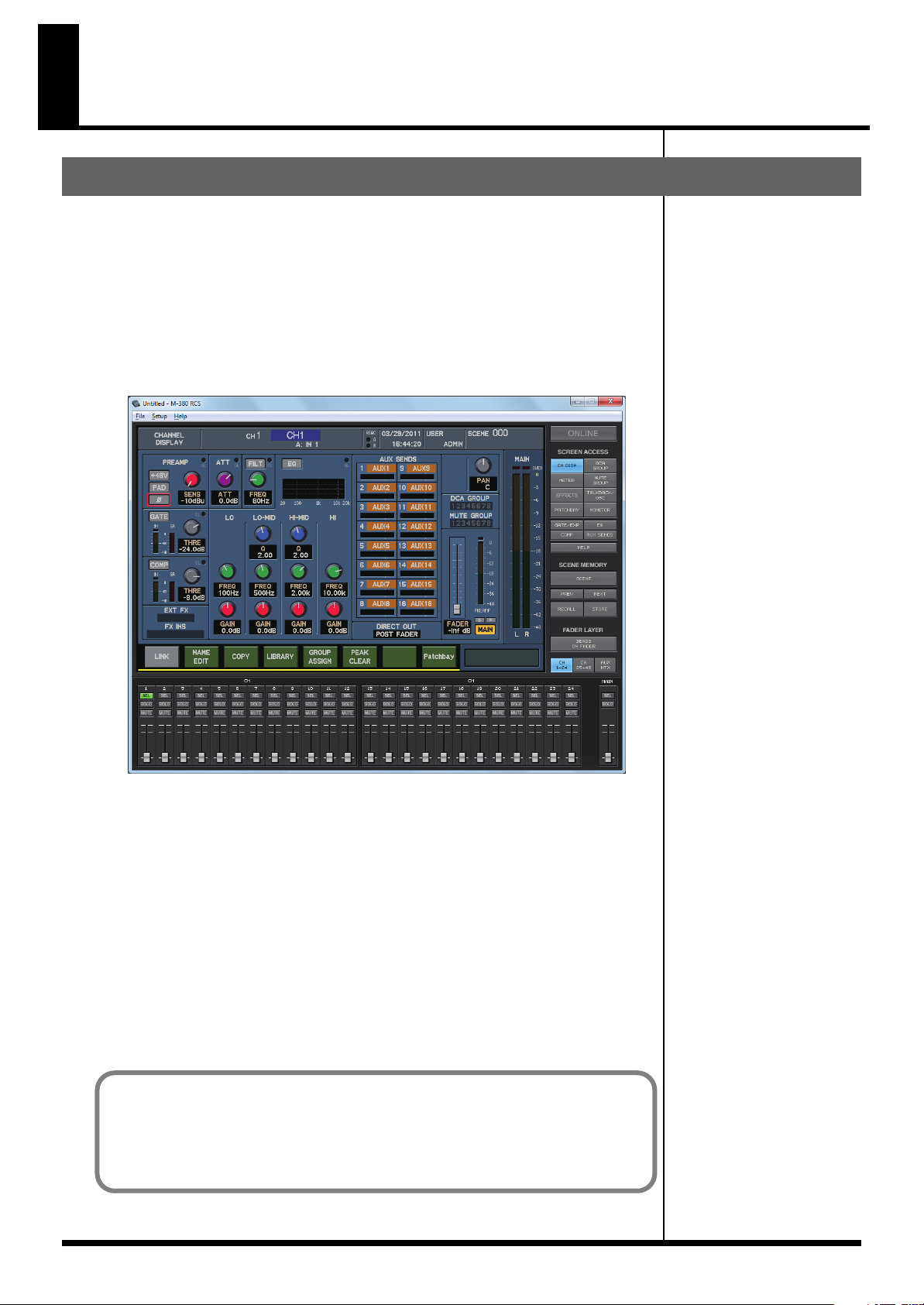
fig.ScrRCS.eps
The application will start up, and the M-380 RCS window will appear.
Exiting the application
2
In the M-380 RCS window, choose “Exit” from the “File” menu.
A message box will appear, asking you to confirm whether you want to save the
current project.
fig.ScrSyncConfirm.eps
• If you click “Yes,” the current project will be saved.
• If you click “No,” the current project will not be saved.
You will exit the application.
A new project will be opened
when the application starts.
9
Page 10
Names of things and what they do
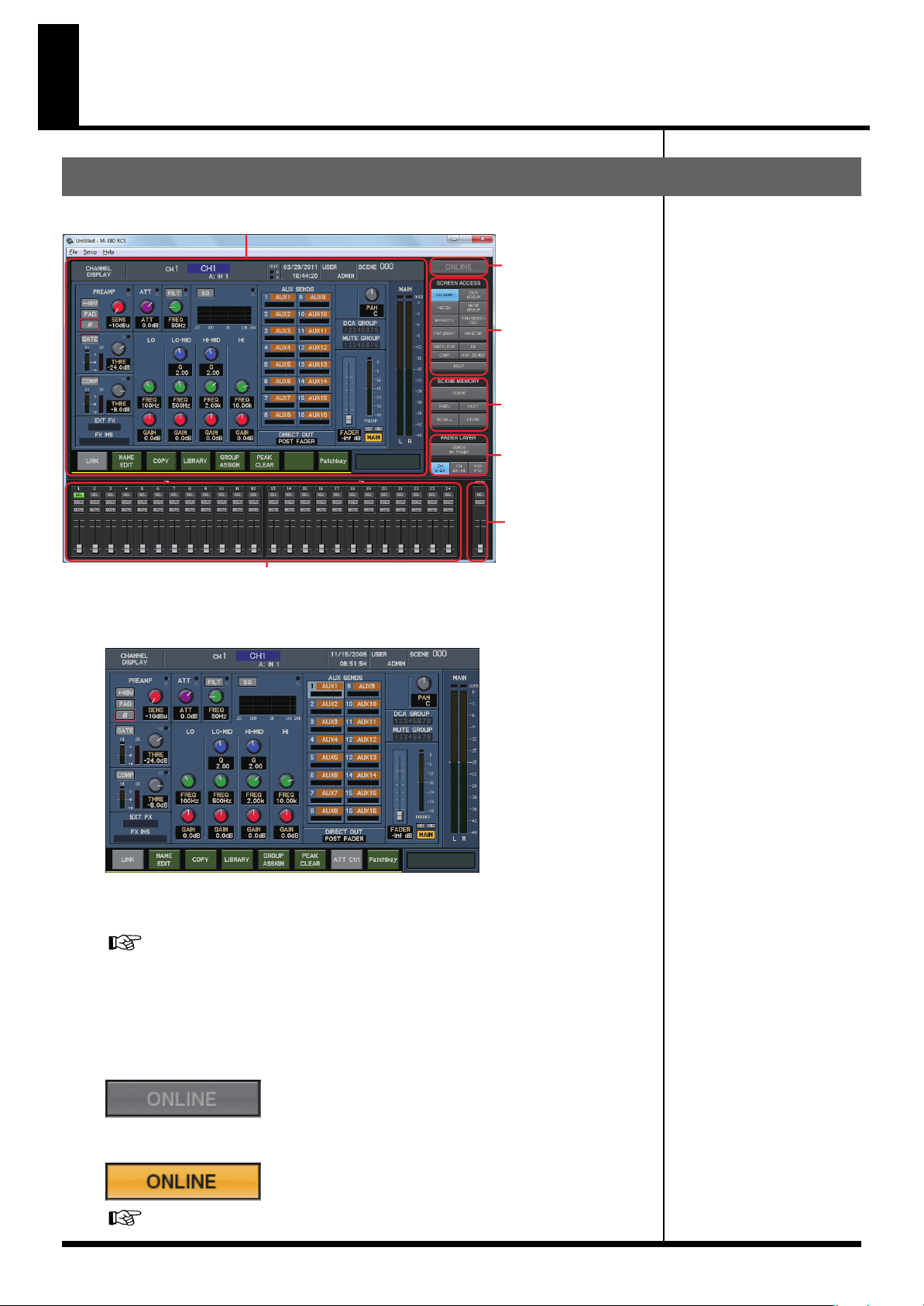
M-380 RCS window
fig.ScrRCSGuide.eps
Basic screen area
Mode button
Screen recall buttons
Scene memory buttons
Fader layer buttons
Main fader module
Fader modules 1–24
Basic screen area
fig.ScrChDisp.eps
This shows a screen of the same design as the screen of the M-380 console itself. You
can use the mouse and keyboard to perform operations in this screen.
"Operations in the main screen area"
(p. 14)
Mode button
This switches the mode of M-380 RCS.
10
●
Offline mode
fig.ScrOffline.eps
●
Online mode
fig.ScrOnline.eps
"Switching between modes"
(p. 18)
Page 11

Screen recall buttons
fig.ScrScreenAccess.eps
These buttons switch the content of the basic screen area. The button
corresponding to the currently shown screen or popup is shown in blue.
CH DISP button Accesses the CHANNEL DISPLAY screen.
METER button Accesses the METER screen.
EFFECTS button Accesses the EFFECTS screen.
PATCHBAY button Accesses the PATCHBAY screen.
DCA GROUP button Accesses the DCA GROUP screen.
MUTE GROUP button Accesses the MUTE GROUP screen.
TALKBACK/OSC button Accesses the TALKBACK/OSC screen.
MONITOR button Accesses the MONITOR screen.
GATE/EXP button Accesses the GATE/EXPANDER popup.
COMP button Accesses the COMPRESSOR popup or LIMITER popup.
EQ button Accesses the EQUALIZER popup.
AUX SENDS button Accesses the AUX SENDS popup.
HELP button Accesses the HELP popup.
Names of things and what they do
Scene memory buttons
fig.ScrScene.eps
These buttons perform scene memory operations for M-380 RCS.
SCENE button Accesses the SCENE screen in the basic screen area. This button is
shown in blue while the SCENE screen is displayed.
PREV button Decrements the scene number by one.
NEXT button Increments the scene number by one.
RECALL button Recalls the mixer parameters from the currently selected scene num-
ber.
STORE button Stores the current mixer parameters to the selected scene number.
11
Page 12

Names of things and what they do
T
Fader layer buttons
fig.ScrLayer.eps
These buttons switch the layer operated by fader modules 1–24. The currently
selected layer is shown in blue.
SENDS ON FADER button
CH1-24 button Assigns CH1–CH24 to fader modules 1–24.
CH25-48 button Assigns CH25–CH48 to fader modules 1–24.
AUX/MTX button or
AUX/DCA button
Accesses the SENDS ON FADER panel.
Assigns AUX1–AUX16 and MATRIX1–MATRIX8,
or AUX1–AUX16 and DCA1–DCA8 to fader modules 1–24.
Fader modules 1–24
fig.ScrFader1-24.eps
Use these faders to operate the input channels, AUX channels, MATRIX channels, and
DCA channels.
SEL button Selects the corresponding channel. The button of the selected chan-
nel is shown in green.
SOLO button Turns a channel’s Solo on/off. The button is shown in orange if Solo is
on.
MUTE button Turns a channel’s Mute on/off. The button is shown in red if Mute is on.
Fader Adjusts the signal level of the channel.
Adjustments made to a
selected channel strip in M-
380 RCS will be reflected in
the appropriate M-380
channel strip, but the M-380
display will not switch its
display to your selected
channel strip in the M-380
RCS.
Main fader module
fig.ScrFaderMain.eps
This fader controls the MAIN L/R.
SEL button Selects the MAIN L/R channel. The button is shown in green when se-
lected.
SOLO button Turns the MAIN L/R channel’s Solo on/off. The button is shown in or-
ange if Solo is on.
Fader Adjusts the signal level of the MAIN L/R channel.
oggling the SEL button, you
will alternate between
selecting the MAIN L channel
and the MAIN R channel.
12
Page 13

SENDS ON FADER Panel
fig.ScrRCSSOF.eps
Names of things and what they do
This panel is shown when SENDS ON FADER button is on.
AUX SELECT 1–16 buttons
SENDS ON FADER button Closes the SENDS ON FADER panel.
CH1-24 button Assigns CH1–CH24 to fader modules 1–24.
CH25-48 button Assigns CH25–CH48 to fader modules 1–24.
AUX/MTX button or
AUX/DCA button
Selects the send-destination AUX.
Assigns AUX1–AUX16 and MATRIX1–MATRIX8,
or AUX1–AUX16 and DCA1–DCA8 to fader modules 1–24.
13
Page 14

Names of things and what they do
T
Operations in the main screen area
The mouse and keyboard are used to perform operations in M-380 RCS’s main screen
area.
Cursor movement
• Up/down/left/right cursor keys
Button operations
• Click a button to turn it on/off
• Move the cursor to a button and press the Enter key to turn it on/off
Function button operations
• Click
• Keyboard “F1” – “F8” keys
Knob operations
• Drag a knob up/down or left/right
• Move the cursor to a knob, and then use the mouse wheel to increase/decrease the value
• Move the cursor to a knob, and press the Page Up key to increase the value or the Page
Down key to decrease it
• Move the cursor to a knob, and press the + key to increase the value or the - key to
decrease it
Fader operations
• Drag a fader knob up/down
• Move the cursor to a fader, and then use the mouse wheel to increase/decrease the value
• Move the cursor to a fader, and press the Page Up key to increase the value or the Page
Down key to decrease it
• Move the cursor to a fader, and press the + key to increase the value or the - key to
decrease it
he cursor is indicated by a
red frame in the Basic screen
area. In M-380 RCS, the cursor
exists only within the Basic
screen area.
You can make fine
adjustments by holding
down the Shift key while you
operate a knob or a fader.
By clicking while you hold
down the Ctrl key, you can
reset the fader value to 0.0
dB.
Send level bar operations
• Drag the bar to left/right
• Move the cursor to a send level bar, and use the mouse wheel to increase/decrease the
value
• Move the cursor to a send level bar, and press the Page Up key to increase the value or
the Page Down key to decrease it
• Move the cursor to a send level bar, and press the + key to increase the value or the - key
to decrease it
By clicking while you hold
down the Ctrl key, you can
reset the value of the send
level bar to 0.0 dB.
List operations
• Use the up/down cursor keys to change the selected item
• Use the mouse wheel to change the selected item
• Drag the scroll bar up/down to scroll the list
Entering a name
In the name entry field of the NAME EDIT popup, you can use the keyboard to enter
a name.
14
Page 15

About the menus
T
File menu
●
New Project
Opens a new project.
●
Open Project...
Opens an existing project (a project that was saved to USB memory by the M-380
console itself, or a project created by M-380 RCS).
●
Save Project
Saves the current project (by overwriting it onto the existing file).
●
Save Project As...
Saves the current project with a different name that you specify.
●
Exit
Exits M-380 RCS.
Names of things and what they do
If you open a project while
online, M-380 RCS will switch
to offline operation.
Setup menu
●
REAC Config...
Opens the REAC Config dialog box.
"REAC input/output settings"
●
Initialize...
Initializes the settings.
"Initializing the settings"
●
Preferences...
Opens the Preferences dialog box.
"Preference settings"
●
LCR Setup...
Opens the LCR Setup dialog box.
"LCR System settings"
Help menu
●
About M-380 RCS...
Opens the About M-380 RCS dialog box, which shows the software version of M380 RCS.
(p. 23)
(p. 24)
(p. 26)
(p. 21)
he REAC Config dialog box
is available only when M-380
RCS is operating offline.
15
Page 16

Using M-380 RCS
Opening and saving a project
Opening a project
Opening a new project
1
From the “File” menu, choose “New Project.”
A message box will appear, asking you to confirm whether you want to save the
current project.
fig.ScrSyncConfirm.eps
• If you click “Yes,” the current project will be saved.
• If you click “No,” the current project will not be saved.
A new project will open.
Opening an existing project file
1
From the “File” menu, choose “Open Project.”
A message box will appear, asking you to confirm whether you want to save the
current project.
fig.ScrSyncConfirm.eps
• If you click “Yes,” the current project will be saved.
• If you click “No,” the current project will not be saved.
fig.ScrOpenProj.eps
16
The “Open” dialog box will appear.
2
Select the desired project file, and click the “Open” button.
The selected project will open.
Project files saved by the M-
380 console itself will be
located in the USB memory’s
“\RSS\M-400\PROJ” folder.
Page 17

Saving a project
Saving a project under its current name (Overwrite)
1
From the “File” menu, choose “Save Project.”
The project will be saved under its current name, overwriting the existing file.
Saving a project under a different name
1
From the “File” menu, choose “Save Project As.”
fig.ScrSaveProjAs.eps
Using M-380 RCS
The “Save As...” dialog box will appear.
2
Specify the file name and location in which you want to save the
project, and click the “Save” button.
The project will be saved.
When a project file saved by M-380 RCS is loaded directly by the M-380 console,
the following settings will not be loaded.
• Settings of the SYSTEM screen (INTERNAL SAMPLING FREQ, BRIGHTNESS, FADER
TOUCH SENSE)
• REAC SETUP settings of the REAC CONFIG popup
• REMOTE popup settings
• USER settings
If you want to save a project
file that you intend to load
into the M-380 console itself,
save the file in your USB
memory’s “\RS\M-400\PROJ”
folder.
17
Page 18

Using M-380 RCS
Switching between modes
Switching to online mode
1
Click the ONLINE button.
fig.ScrOffline.eps
fig.ScrSync1.eps
M-380 RCS will be in offline
mode when you start up or
when you open a project file.
Before you continue, start up
the M-380 console, and use a
USB cable to connect it to
your computer.
The “Synchronize” dialog box will appear.
2
In the “Project” field, specify the project to which you will
synchronize: the project on the M-380 console or the project in M380 RCS.
Read from CONSOLE
Send to CONSOLE The project will be sent from M-380 RCS to the M-380 console.
The project will be loaded from the M-380 console into M-380
RCS.
3
If you selected “Send to CONSOLE” in step 2, use the “Option (Send
to CONSOLE)” field to specify whether you want to send the user
library.
If you select the “Send User Libraries” option, the user library will be sent from M380 RCS to the M-380 console.
4
Click “OK.”
“Send User Libraries” will
overwrite current libraries
unless they are locked. Be
sure to lock or save any
needed M-380 libraries to
USB memory prior to
sending.
18
If you selected “Read from CONSOLE” in step 2, the current project will be closed,
a new project will be opened, and then synchronization will begin.
A message box will ask whether you want to save the current project.
fig.ScrSyncConfirm.eps
• If you click “Yes,” the current project will be saved (by overwriting).
• If you click “No,” the current project will not be saved.
• If you click “Cancel,” project synchronization will be cancelled.
Page 19

If you selected “Send to CONSOLE” in step 2, a message box will ask you to
T
confirm the project synchronization.
fig.ScrSyncConfirm2.eps
When you click “OK,” project synchronization will begin.
Using M-380 RCS
5
When project synchronization is completed, M-380 RCS will switch
to online mode.
fig.ScrOnline.eps
In online mode, you’ll be able to remotely control the M-380 console from M-380
RCS.
If you selected “Send to CONSOLE” in step 2 and the M-380’s scene memory or
user library contains any locked data, a message box will ask you whether you
want to overwrite the data. If you click “OK,” the data will be overwritten. If you
click “Cancel,” project synchronization will be cancelled.
fig.ScrSyncConfirmLock1.eps
he M-380 console will show
a progress message while the
project is being
synchronized. Operations on
the M-380 will be disabled
during this time.
On the “Synchronize” dialog box, you can adjust the data transfer speed.
If an error is shown while synchronization, set the “Transfer” slider to “Slow”
position.
19
Page 20

Using M-380 RCS
Switching to offline mode
1
Click the ONLINE button.
fig.ScrOnline.eps
2
M-380 RCS will switch to offline mode.
fig.ScrOffline.eps
20
Page 21

REAC input/output settings
T
In offline mode, you can make virtual settings for an input/output unit (e.g., S-1608
stage unit, S-0816 FOH unit, S-4000S 40-channel I/O modular rack) that will later be
connected to the M-380 console. This lets you make preamp gain settings or input/
output patching ahead of time, to specify the M-380’s input/output settings that will
be used at the actual performance.
1
From the “Setup” menu, choose “REAC Config.”
fig.ScrReacConf.eps
Using M-380 RCS
Settings in the REAC Config
dialog box are used to
supplement offline mode.
When you load a project on
the M-380 console itself, or
switch to online mode, the
settings for the input/output
units that are actually
connected to the M-380 will
be applied.
he “REAC Config” dialog box
is unavailable in online
mode.
The “REAC Config” dialog box will appear.
2
Access the “REAC A tab” (or “REAC B” tab).
3
From the pulldown menu, select the input/output unit that you will
connect to REAC A (or REAC B).
The pulldown menu gives you the following choices.
(No Device) No connection
S-1608 S-1608 stage unit
S-0816 S-0816 FOH unit
S-4000S S-4000S 40-channel I/O modular rack
S-0808 S-0808 8x8 I/O UNIT
S-4000M REAC MERGE UNIT S-4000M
S-MADI REAC MADI BRIDGE S-MADI
FOH SPLIT M-380 split operating as the FOH console (REAC A only)
4
Access the “REAC B” tab, and make REAC B settings as described in
steps 2 and 3.
Choose FOH if the split from
another M-380 being
operated as a FOH console
will be connected to REAC A
and used as a monitor/
broadcast console.
21
Page 22

Using M-380 RCS
Changing the S-4000S module configuration
If you choose S-4000S in the REAC Config dialog box, a 32-in/8-out configuration will
be applied. To change the S-4000S module configuration, proceed as follows.
fig.ScrReacConfS4KS.eps
1
In the REAC Config dialog box, click the “Config” button.
fig.S4KSConf.eps
The “S-4000S Config” dialog box will appear.
2
Use the Slot1–Slot10 pulldown menus to specify the module for
each slot.
The pulldown menu gives you the following choices.
• Blank (empty slot)
• SI-AD4 (4ch Analog In)
• SI-AES4 (4ch Digital In)
• SO-DA4 (4ch Analog Out)
• SO-AES4 (4ch Digital Out)
3
Press the “OK” button to close the S-4000S Config dialog box.
If an error is displayed in step 3, one of the following situations may have
occurred. Correct the mistake, and click “OK” once again.
• A module of a differing type is incongruously located between modules; e.g., input
module, output module, input module
• A module of a differing type begins at an even-numbered slot
• Only the odd-numbered slot of adjacent odd-numbered/even-numbered slots is
blank
22
Page 23

Initializing the settings
1
From the “Setup” menu, choose “Initialize.”
fig.ScrInit.eps
The “Initialize” dialog box will appear.
2
Place a check mark in the sections that you want to initialize.
• Mixer Parameter
• System Setting
• Scene Memory
• User Library
Using M-380 RCS
3
Click “OK.”
A message box will ask you to confirm the initialization operation.
fig.ScrInitConf.eps
4
Click “OK” to execute the initialization.
23
Page 24

Using M-380 RCS
T
Preference settings
Here’s how to make preference settings within M-380 RCS. The settings you make
here will not be reflected in the M-380 console.
1
From the “Setup” menu, choose “Preferences.”
fig.ScrPref.eps
The “Preferences” dialog box will appear.
2
Select the desired items in the “Preferences” dialog box.
● Level Meter
If you select this, level meter data will be received in online mode.
● Confirmation
These enable/disable various confirmation messages that appear in the basic
screen area. A particular type of confirmation message can be enabled by
selecting the corresponding check box.
Scene/Library Store Confirmation messages when storing a scene or library
Scene/Library Recall Confirmation messages when recalling a scene or library
Patchbay Change Confirmation messages when changing the input/output
● Ch Select
These items specify what will happen when you select a channel. The items you
select will be enabled.
Channel SELECT follows SOLO button
Channel SELECT changes with Layer Selection
CHANNEL DISPLAY follows CH SELECT button
patchbay settings
When you press [SOLO], that channel will be selected.
When you select a fader layer, the most recently
selected channel of that layer will be selected.
Pressing [SEL] will make the CHANNEL DISPLAY
screen appear.
If the processing load of M-
380 RCS is too great in online
mode, you can lighten it by
clearing the Level Meter
check box.
● Home Screen
This chooses the home screen. The screen you select here will be the home
screen.
CHANNEL DISPLAY The CHANNEL DISPLAY screen will be used as the home
METER The METER screen will be used as the home screen.
screen.
he home screen is what
appears when you click the
button of the currently
displayed screen (the button
shown in blue).
24
Page 25

● Fader Layer
This chooses the fader layer buttons (p. 12).
[CH1-24] [CH25-48] [AUX/DCA] CH1-24, CH25-48. AUX/DCA buttons
[CH1-24] [CH25-48] [AUX/MTX] CH1-24, CH25-48, AUX/MTX buttons
● Main Fader
If you select “SENDS ON FADER MASTER”, the MAIN fader module becomes the
send-destination AUX fader, while the SENDS ON FADER mode is on.
● DCA [SEL]
This selects the operation that pressing [SEL] preforms when DCA 1 through 8
has been called up to the fader module section. The selection items are as
indicated below.
OFF [SEL] is disabled.
ASSIGN Access the DCA GROUP ASSIGN popup.
Using M-380 RCS
25
Page 26

Using M-380 RCS
LCR System settings
1
From the “Setup” menu, choose “LCR Setup...”
fig.ScrLCRSetup.eps
The “LCR Setup” dialog box will appear.
2
Use the LCR SYSTEM check box to turn LCR System on/off.
If this check box is selected, LCR System will be on. If it is cleared, LCR System will
be off.
For more information about
the LCR features, refer to the
M-380 owner's manual.
3
If you've selected the LCR SYSTEM check box, use the MAIN C
selection box to select the AUX that will be used as MAIN C.
4
Click “OK.”
A message box will appear, asking you to confirm the operation.
● If the LCR SYSTEM check box is selected
fig.ScrLCRSetup_conf1_e.eps
● If the LCR SYSTEM check box is cleared
fig.ScrLCRSetup_conf2_e.eps
26
5
Click “OK.”
The item shown in the message box of step 4 will be initialized, and the LCR
system setting will be changed.
Page 27

M-48 settings
You can manage and make settings for the M-48 Live Personal Mixer in the same way
you do from the M-380 console.
M-380 RCS cannot use the following functionality.
• Accessing and operating the M-48 LOAD/SAVE popup
• Monitoring the source in the M-48 SOURCE LEVEL/PAN popup
• Updating the M-48 system program
Making M-48 settings in offline mode
In offline mode, the M-48 list in the M-48 MANAGER popup will show a unit
named “Virtual.”
fig.ScrM48Virtual.eps
Using M-380 RCS
For details on the M-48 Live
Personal Mixer, refer to the
“M-48 Owner's Manual.”
For details on M-48 settings,
refer to the M-380 owner's
manual.
Settings you make for the “Virtual” unit can be stored in the M-48 library. Settings
from the M-48 library can be applied to a physical M-48 in the following ways.
● A project file saved by M-380 RCS can be loaded into the M-380
console.
In the SYSTEM screen's LOAD/SAVE popup, select the M-48 LIBRARY check box to
load it.
"Saving a project" (p. 17)
● Switch M-380 RCS to online mode.
The M-48 library data in M-380 RCS can be recalled to a physical M-48 unit.
"Switching to online mode" (p. 18)
You cannot perform the following operations for the “Virtual” unit.
• Edit the unit name “Virtual”
• Store or recall memories
• Set the MEMORY SAFE function, or make output mute settings
Settings made for the
“Virtual” unit will be
discarded when you switch
to online mode. Before
switching to online mode,
you must save these settings
to the M-48 library and then
save the project.
Even if you switch to online
mode, the M-48 library of M-
380 RCS and the M-380
console will remain
unaffected.
M-48 settings in online mode
The M-48 MANAGER popup will show the M-48 units that are actually connected.
You can edit and manage each M-48 unit using the same operations you do from the
M-380 console.
For details on M-48 settings,
refer to the M-380 owner's
manual.
27
Page 28

Offline mode
Operation in offline mode
fig.OfflineEdit.eps
Edit within M-380RCS
Save the project fileLoad the project file
USB memory
USB memory
Offline mode lets you edit M-380 project files when you don’t have an M-380 console
at hand. A project file you’ve edited using M-380 RCS can be loaded by the M-380
console.
Load the project fileSave the project file
Work flow in offline mode
1
On the M-380 console, save a project file to USB memory.
fig.OfflineEditStep1.eps
Save the project file
USB memory
2
Start up M-380 RCS.
fig.ScrRCS.eps
28
A new project will open.
3
In M-380 RCS, open the project file from USB memory.
fig.OfflineEditStep2.eps
Load the project file
USB memory
Project files saved by the M-
380 console will be located in
the “\RSS\M-400\PROJ” folder
of the USB memory.
Page 29

4
Edit the project.
If necessary, use the “Reac Config” dialog box to make REAC input/output
configuration settings.
5
Save the project file, either by overwriting the existing file or under
a different name.
fig.OfflineEditStep3.eps
Save the project file
USB memory
6
Exit M-380 RCS.
7
On the M-380 console, load the project file from USB memory.
fig.OfflineEditStep4.eps
Load the project file
Offline mode
If you’re saving a project file
that you wish to load into the
M-380 console, save it in the
“\RSS\M-400\PROJ” folder of
your USB memory.
USB memory
When a project file saved by M-380 RCS is loaded by the M-380 console, the
following settings will not be loaded.
• Settings of the SYSTEM screen (INTERNAL SAMPLING FREQ, BRIGHTNESS, FADER
TOUCH SENSE)
• REAC SETUP settings of the REAC CONFIG popup
• Settings of the REMOTE popup
• USER settings
29
Page 30

Online mode
Operation in online mode
fig.OnlineEdit.eps
Control the M-380
Operations on the M-380 are fed back
Online mode lets you remotely control the M-380 console from M-380 RCS. Level
meter data from the M-380 console and operations performed on the M-380 console
are also sent to M-380 RCS.
Synchronization in online mode
If you’ve cleared the “Level
Meter” check box in the
preference settings, level
meter data will not be sent
from the M-380 console.
(Preference settings (p. 24))
In online mode, the following operations are synchronized between M-380 RCS and
the M-380 console.
• Mixer parameter operations
• Scene memory recall and store operations
• Scene list editing
• Library recall operations
The following operations are not synchronized.
• Switching between screens
• Storing or renaming user library items
• Selection of scene numbers using the [PREV] [NEXT] buttons, etc.
Work flow in online mode
1
Start up the M-380 console, and use a USB cable to connect it to your
computer.
fig.USBConnection.eps
30
To USB Port
USB cable
To the rear panel
USB connector
Page 31

2
Start up M-380 RCS.
fig.ScrRCS.eps
A new project will open.
3
If necessary, open an existing project file.
Online mode
4
Click the “ONLINE” button to begin synchronizing the project and
enter online mode.
fig.ScrOnline.eps
Switching to online mode (p. 18)
5
In M-380 RCS, remotely control the M-380 console.
fig.OnlineEdit.eps
Control the M-380
Operations on the M-380 are fed back
6
Click the “ONLINE” button to choose offline mode.
fig.ScrOffline.eps
7
Save the project if desired.
8
Exit M-380 RCS.
31
Page 32

Appendix
Warning/error messages
Error messages common to the M-380
Warning/error messages shown in the basic screen area are the same as on the M380 console. For details on warning/error messages, refer to “Warning/error
message list” in the “M-380 owner’s manual.”
Error messages specific to M-380 RCS
Message Explanation
Cannot find M-380 console. The M-380 console was not found.
Can’t get an online connection
with the M-380 console (p. 32)
The M-380 console does not respond. The console does not respond.
Can’t get an online connection
with the M-380 console (p. 32)
The M-380 console refused the
connection.
The USB connection was broken. The USB connection or cable has been
Communication error Communication error has occurred.
S-4000S configuration error The S-4000S configuration has some prob-
The console might be busy doing something else intensive. Try again.
changed in some way as to cause a disconnect.
Can’t get an online connection
with the M-380 console (p. 32)
lem.
Changing the S-4000S module
configuration (p. 22)
Troubleshooting
● Can’t get an online connection with the M-380 console
• The USB cable is not connected correctly
Connection to the M-380 (p. 7)
• The correct settings have not been made on the M-380 console
Settings on the M-380 console (p. 7)
• The M-400 Driver is not installed correctly
About the M-400 Driver (p. 6)
• You’re using an incompatible operating system
Operating requirements (p. 6)
• The data transfer is too fast
(p. 19)
32
2PS
 Loading...