

Page 1
M-200i Remote
Owner's Manual
M-200i Remote is an application for controlling the Roland M-200i V-Mixer live mixing console.
You can remotely control various functions of the M-200i unit using this application. This
document describes the functions of the M-200i Remote.
The explanations in this document include illustrations that depict what should typically
be shown by the display. Note, however, that the application you are using is a newer,
enhanced version, so what you actually see in the display may not always match what
appears in this manual.
Copyright © 2013 ROLAND CORPORATION
All rights reserved. No part of this publication may be reproduced in any form without the written
permission of ROLAND CORPORATION.
* Roland is either registered trademark or trademark of Roland Corporation in the United States and/or other countries.
* All product names mentioned in this document are trademarks or registered trademarks of their respective owners.
1PS
Page 2

Contents
About This Application .........................................................................................3
Overview of This Application ............................................................................................................................................................3
Synchronizing the Operations on the M-200i unit and the Display of iPad ....................................................................3
Channel Operations ..............................................................................................5
About Operating Screens ...................................................................................................................................................................5
About Various Screens on Channel Parameter Section ..........................................................................................................6
Channel Strip Screen ..............................................................................................................................................................6
Change View Mode of the Channel Strip Screen .........................................................................................................7
Switch to Various Setting Screens of the Channel ....................................................................................................................9
CH-EDIT Screen ..................................................................................................................................................................... 11
GATE Screen ........................................................................................................................................................................... 14
COMP Screen ......................................................................................................................................................................... 16
EQ Screen ................................................................................................................................................................................ 17
SENDS Screen ........................................................................................................................................................................ 18
Setting the V-Mixer (DISPLAY Button) ...............................................................20
Call up the Setting Screens ............................................................................................................................................................. 20
METER Screen ...................................................................................................................................................................................... 21
SETUP Screen ....................................................................................................................................................................................... 22
DCA Group Screen ............................................................................................................................................................................. 25
Mute Group Screen ........................................................................................................................................................................... 26
Eects Screen ...................................................................................................................................................................................... 27
GEQ Screen ........................................................................................................................................................................................... 29
USB Recorder Screen ........................................................................................................................................................................ 31
Music Control Screen ........................................................................................................................................................................ 32
About Other Functions .......................................................................................33
About Scene List ................................................................................................................................................................................. 33
About Sends on Fader ...................................................................................................................................................................... 34
About [FUNCTION] ............................................................................................................................................................................ 35
Copy/Paste .............................................................................................................................................................................. 35
Library ....................................................................................................................................................................................... 36
Functions on Various Screens .......................................................................................................................................... 37
2
Page 3
About This Application
Overview of This Application
This application makes it possible to adjust numerous mixing parameters from a variety of listening points on the stage or around
the room, away from the M-200i which is typically positioned in a xed location.
Combined with the easy operation aorded by the iPad’s large screen and Multi-Touch interface, this application makes it easy to
view and control all key M-200i features.
In addition to remote control, physical buttons and knobs on the M-200i can be synchronized with the M-200i Remote parameters.
The M-200i can be controlled simultaneously from up to three iPads:
a) via the dedicated dock cable,
b) the Roland WNA-1100-RL dedicated USB wireless adapter, and
c) a wireless LAN device.
Depending on the size and complexity of the environment, an operator can choose any or all of these connection types.
About Booting and Quitting of this Application
Refer to “Setup Guide” for booting/quitting of this application and the connection with the M-200i unit.
Synchronizing the Operations on the M-200i unit and the Display of iPad
You can synchronize the operations on the M-200i unit (knob/cursor operations, layer selection, etc.) and the display of iPad.
Execute the following settings for synchronization.
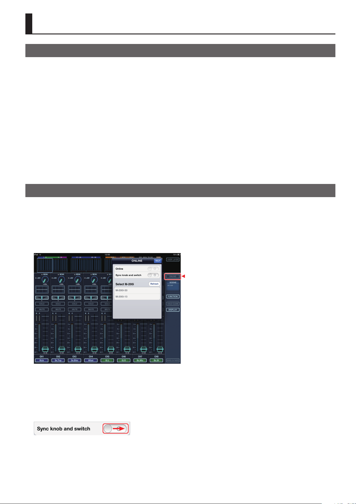
1. Open ONLINE screen
Tap [ONLINE] button to open the ONLINE screen.
* Tap [HELP] button on ONLINE screen to open the “Setup Guide”.
g.open-online.eps
2. Connect the M-200i and the iPad
Read the “Setup Guide” and connect the M-200i and the iPad.
3. Start synchronizing
Tap or slide right the [Sync knob and switch] button. Your operations on the M-200i unit are reected on the displays of the iPad
application.
g.turn-on-sync.eps
4. Terminate the synchronizing
Tap or slide left the [Sync knob and switch] button to terminate synchronized display.
3
Page 4
About This Application
Detailed Settings of Synchronized Display
Open the screen below to execute the detailed settings.
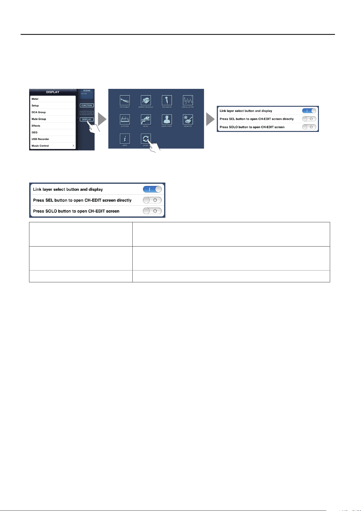
1. Open SYNC screen
Tap [DISPLAY] button and select [SETUP] to open the SETUP screen. Select [SYNC] on the SETUP screen to open the SYNC screen.
g.setup-sync.eps
2. Select the parameters for synchronization
You can select following parameters.
g.sync-parameter.eps
Link layer select button and display Turn this ON to synchronize the layer selection on the M-200i unit and the layer group display on
the Overview Section (p. 5) on this application.
Turn this OFF if you want to operate for dierent layers independently on the M-200i unit and on
Press SEL button to open CH-EDIT screen directly Turn this ON to open the CH-EDIT screen (p. 11) of the channel selected when pressing the
Press SOLO button to open CH-EDIT screen Turn this ON to open the CH-EDIT screen of the channel selected when pressing the [SOLO]
this application.
[SEL] button on the M-200i unit.
If you turn this OFF, the Channel Strip screen (p. 6) that includes the selected channel is
opened. Press the [SEL] button again to open CH-EDIT screen of that channel.
button on the M-200i unit.
If Multiple iPads are Connected
If multiple iPads are connected to the single unit of the M-200i, only the iPad which started synchronized display rst is valid. Other
iPads cannot use the Synchronized Display function.
4
Page 5
Channel Operations
About Operating Screens
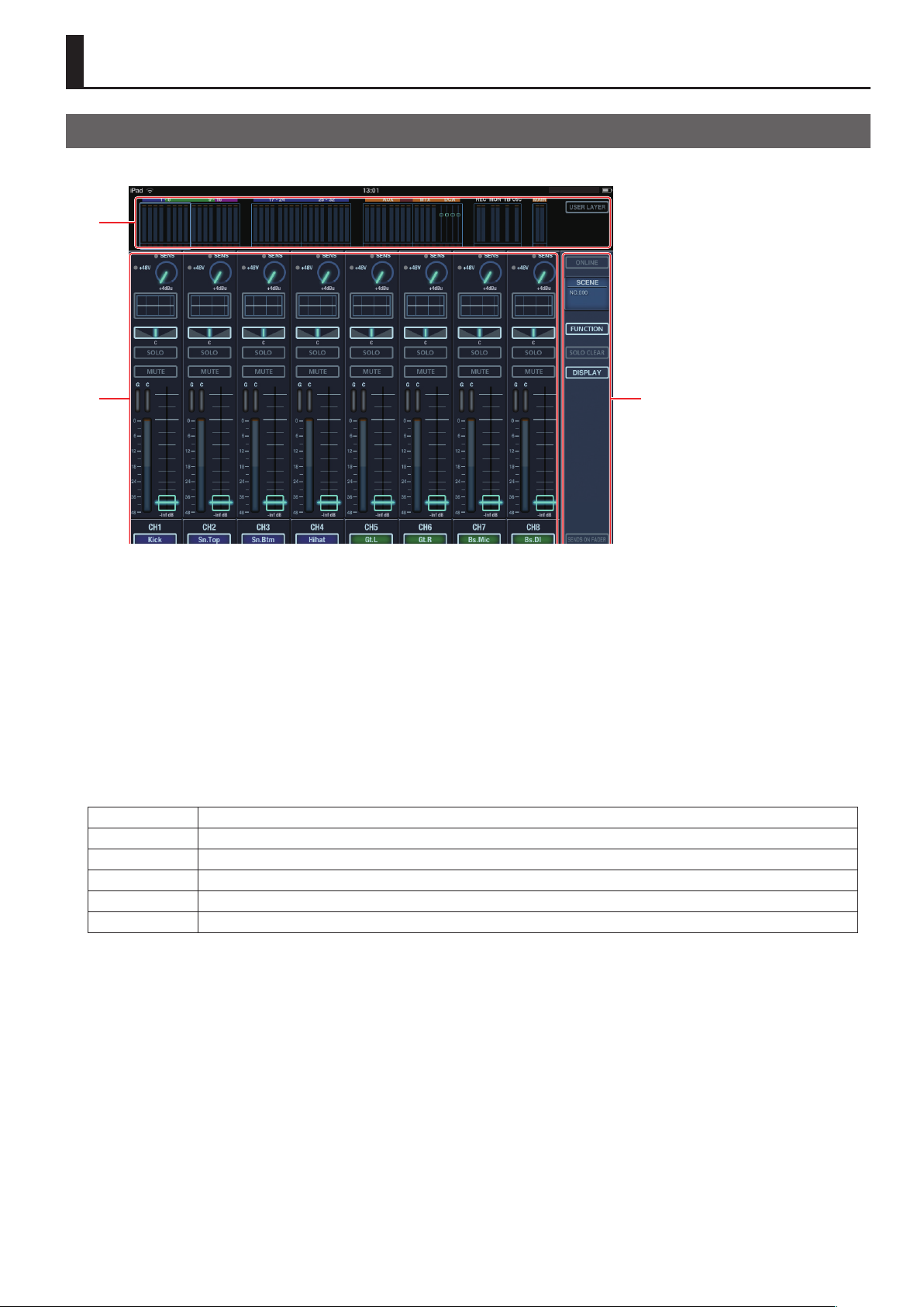
Upon starting the M-200i Remote, the Channel Strip screen as shown below will appear.
g.channel-strip.eps
1
2 3
1 Overview Section
This section displays level meters of in/out channels and mute on/o statuses. Tapping a group of meters will switch the display of
the Channel Parameter section.
• CH 1-8, 9-16, 17-24, 25 - 32
• AUX 1 - 8
• MTX 1-4/DCA 1-4
• REC, MON, TB, OSC
• MAIN LR
You can also switch to user layer screen by tapping the [USER LAYER] button.
2 Channel Parameter Section
You can change various settings of the displayed channel.
3 Side Panel
The following buttons are located on the side panel. You can switch the screen or call up various functions using these buttons.
ONLINE This calls up the popup that is used for connection of the iPad and the M-200i. Refer to the “Setup Guide” for connection.
SCENE This calls up the Scene List (p. 33).
FUNCTION This calls up various functions depending on the current screen (p. 35).
SOLO CLEAR Tap this to clear the solo. If solo of any channel is on, this button ashes.
DISPLAY Tap this to select the type of settings you wish to control on the M-200i (p. 20).
SENDS ON FADER Tap this to switch to Sends on Fader mode (p. 35). You can select the target bus on the popup.
5
Page 6
Channel Operations
About Various Screens on Channel Parameter Section
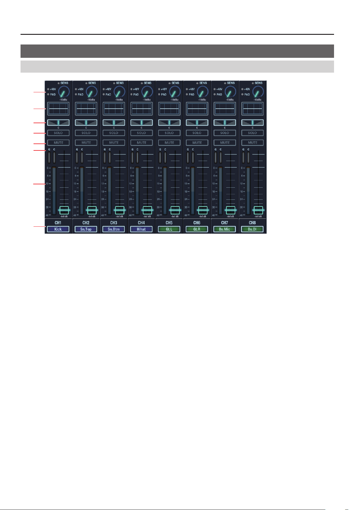
Channel Strip Screen
g.channel-parameter.eps
1
2
3
4
5
6
7
8
1 Preamp Control
• SENS Move the knob with up/down drag operation to control the preamp gain.
The indicator above the knobs light up in green when the signal is detected, light up in orange when clipping.
• +48V The indicator lights up when the phantom power is turned on.
• PAD The indicator lights up when PAD is turned on.
* For channels where no input is patched, SENS/+48V/PAD are not indicated.
2 Channel EQ Display
This part shows the EQ curve for channels. Tap here to switch to the Channel EQ setup screen (p. 17).
3 Pan
Move the sliders with left/right drag operation to control the pan. Double tap the slider to make it return to the center position.
4 SOLO Button
This turns on/o the solo of channels. If solo is turned on for any channel, the [SOLO CLEAR] button on the side panel ashes.
5 MUTE Button
This mutes/unmutes channels.
6 GR Meters
These meters indicate the gain reduction level of channel dynamics. Gate/Comp meters for CH 1-32 and Limiter meters for AUX/
MTX/MAIN.
7 Level Meters and Faders
Meters indicate the level of channels. You can move the fader with up/down drag operation.
8 Channel Label Display
This part displays the channel label and the channel’s label color.
6
Page 7
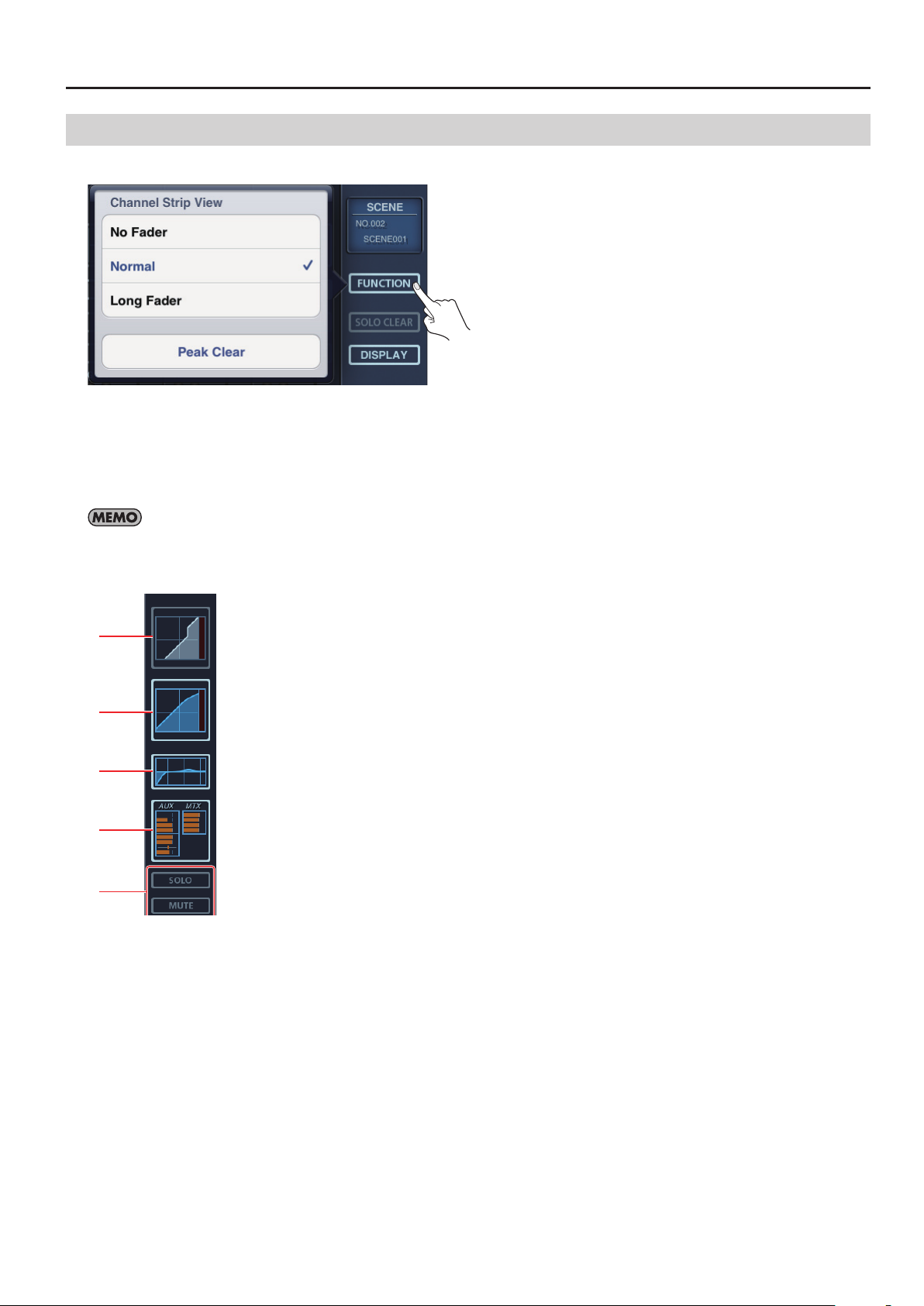
Change View Mode of the Channel Strip Screen
Tap the [FUNCTION] button on side panel to call up the popup below.
g.view-popup.eps
• No Fader
• Normal (default view mode)
• Long Fader
* Tap [Peak Clear] on lower part of the screen to make the peak display of level meters disappear.
No Fader Mode
Channel Operations
No Fader Mode matches when you operate faders on the M-200i unit and do not need to see a display of faders on the iPad.
No Fader Mode of Input Channels
g.input-no-fader.eps
1
2
3
4
5
1 GATE Display
GATE graph is displayed here. Tap this part to open the GATE screen (p. 14).
2 COMP Display
COMP graph is displayed here. Tap this part to open the COMP screen (p. 16).
3 EQ Display
EQ graph is displayed here. Tap this part to open the EQ screen (p. 17).
4 SENDS Display
SENDS setting is displayed here. Tap this part to open the SENDS screen (p. 18).
5 SOLO/MUTE Buttons
Tap to turn on/o solo or mute of the channel.
7
Page 8
Channel Operations
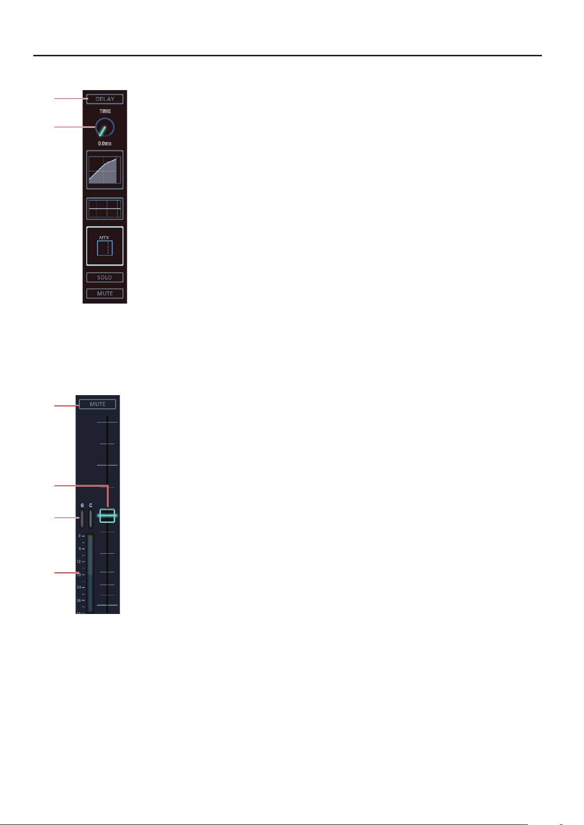
No Fader Mode of Output Channels
g.output-no-fader.eps
1
2
1 DELAY Button
Tap to turn on/o the delay.
2 DELAY TIME
Adjust the delay amount with up/down drag operation.
Long Fader Mode
g.long-fader.eps
1
2
3
4
1 MUTE Button
Tap to turn on/o mute of the channel.
2 Fader
This remotely controls the channel fader.
3 G/C Meters
These indicate the levels described below.
• G Gain reduction level of the GATE
• C Gain reduction level of the COMP
* Depending on the selected channel, these are not displayed.
4 Level Meter
This indicates the channel level.
8
Page 9
Channel Operations
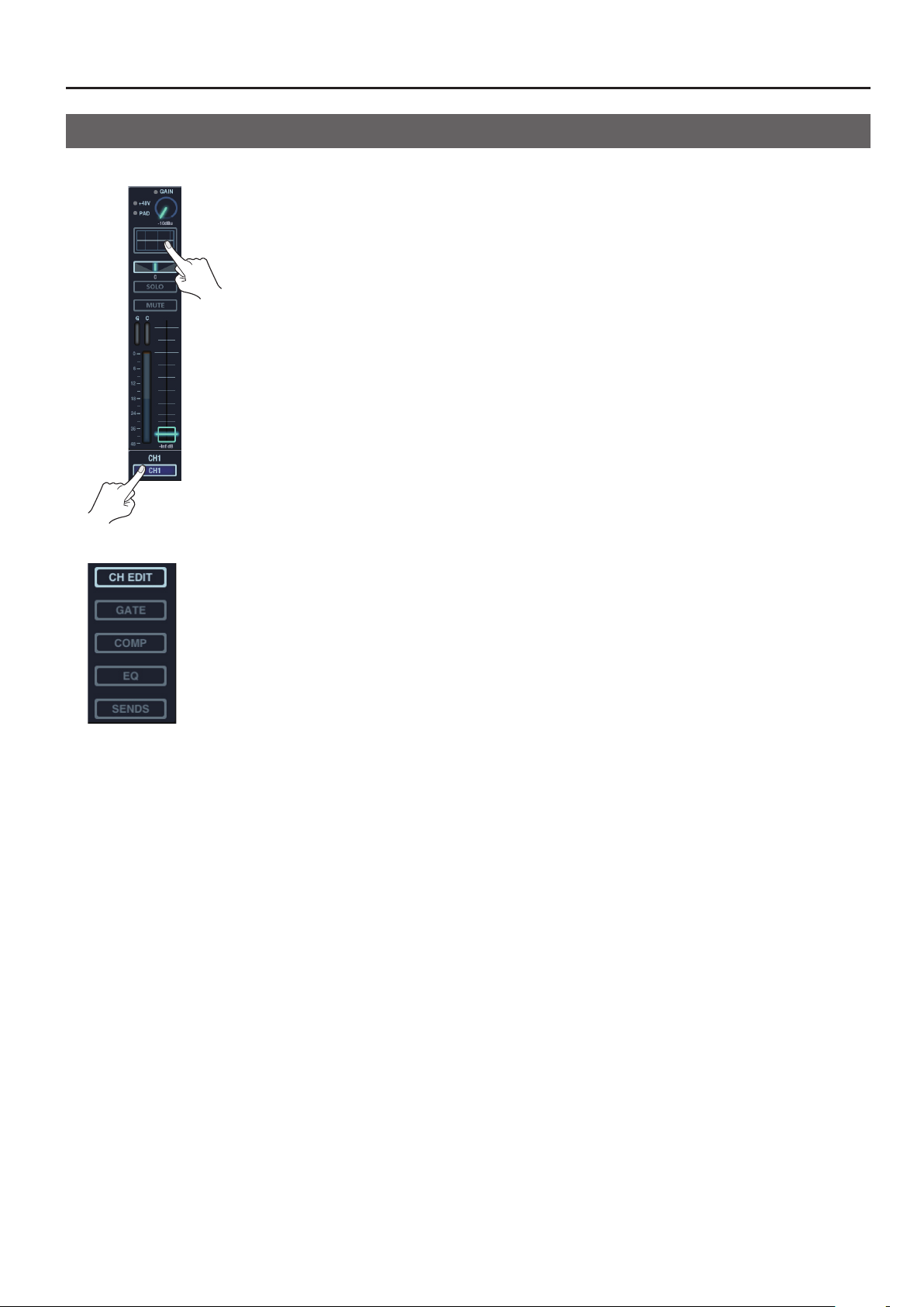
Switch to Various Setting Screens of the Channel
Tap the channel EQ display or channel label display on the channel strip screen to switch to various setting screens of the channel.
g.switch-to-setup.eps
Select the setting screen tapping the buttons on side panel.
g.setup-select.eps
• CH EDIT (p. 11)
• GATE (p. 14)
• COMP (p. 16)
• EQ (p. 17)
• SENDS (p. 18)
* GATE can be selected for input channels only. You cannot select it for output channels.
9
Page 10
Channel Operations
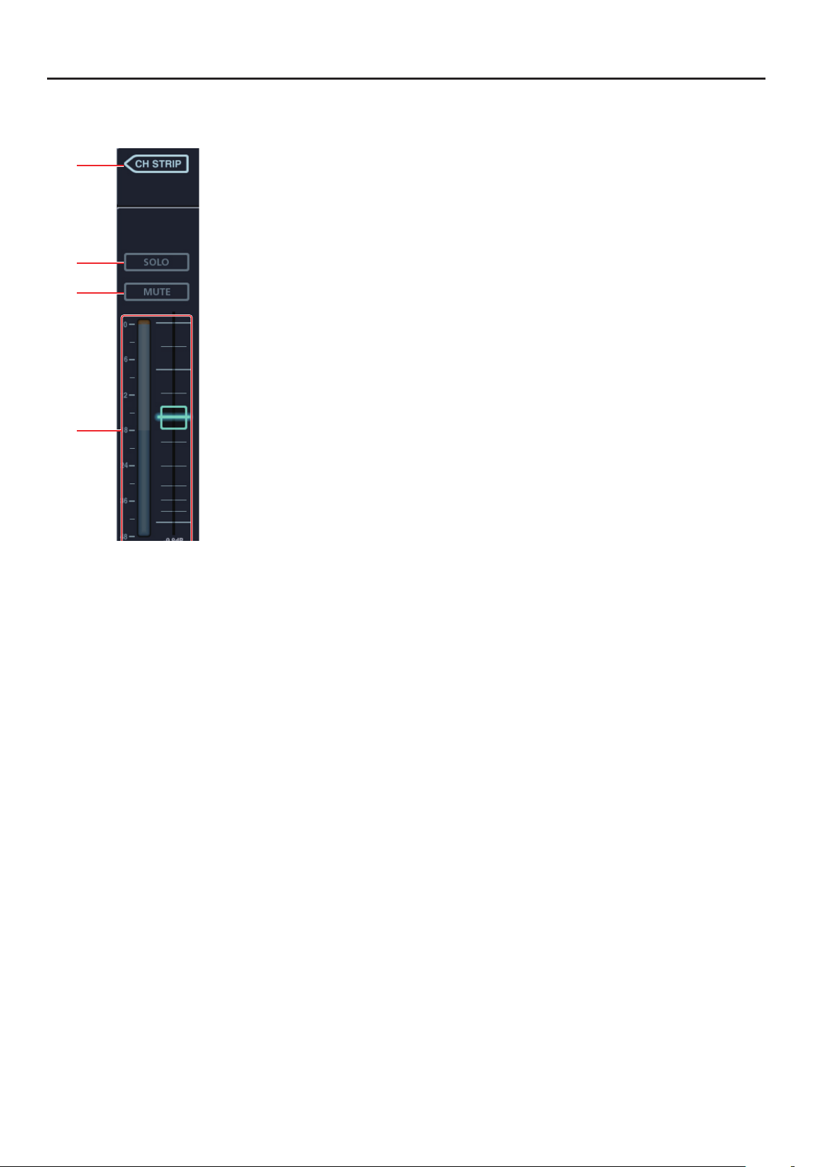
Common Parameters for Various Screens
The parameters below are displayed on left side of CH EDIT screen, GATE screen, COMP screen, EQ screen and SENDS screen
g.meter.eps
1
2
3
4
1 CH STRIP Button
Tap this to return to the channel strip screen.
2 SOLO Button
Tap this to turn on/o solo of the channel.
3 MUTE Button
Tap this to turn on/o mute of the channel.
4 Level Meter and Fader
This indicates the channel level and drag up/down the fader to adjust level.
10
Page 11
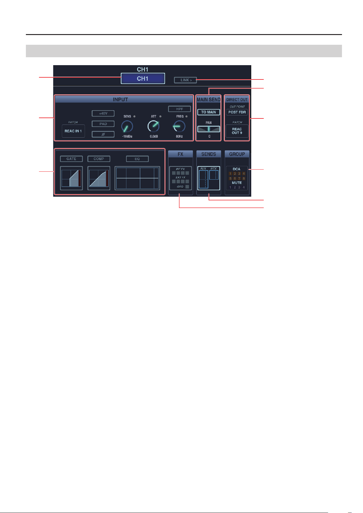
CH-EDIT Screen
g.ch-edit.eps
Channel Operations
1
4
5
2
3
6
7
8
1 Channel Label and Color Label
Tap this to edit channel label and color label. Tap [Name Edit] to open the label name edit screen. Tap [Color Label] to open label
color selection screen.
2 INPUT Section
Use this section to change input settings. Refer to “About Input Section” (p. 12).
* When an output channel is selected, only the attenuator (ATT) appears in this section.
3 Dynamics Section
Turn on/o or call up setting screens of GATE/COMP/EQ. Refer to “About Dynamics Section” (p. 12).
* When an output channel is selected, COMP (LIMITER)/EQ appear in this section.
4 LINK Button
Tap this turn on/o the stereo link of odd/even numbered channels.
5 MAIN SEND
This appears when input channel or AUX is selected. Tap [TO MAIN] to turn on/o the main send use the slider here for pan setting.
6 Output Section
Control the output settings. Refer to “About Output Section” (p. 13).
7 GROUP
This indicates the group assign status of channels. Tap this to call up the assign screen of DCA Group and Mute Group.
8 SENDS
This indicates bus send levels. Tap this to switch to the SENDS screen (p. 18).
9 FX
This indicates the eect assign status to channels. When any eects are assigned, tap this to switch to the Eects/GEQ screen.
11
Page 12
Channel Operations
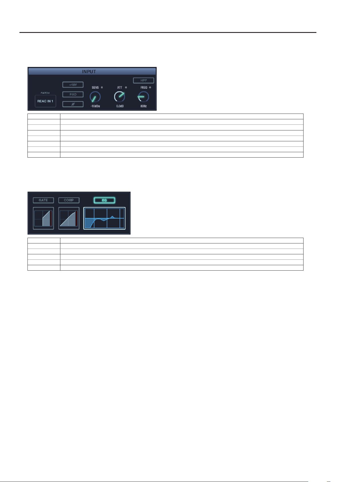
About INPUT Section
* The screen below and the explanations are for input channels. When an output channel is selected, only the attenuator (ATT) setting is possible in
this section.
g.input-senction.eps
PATC H Tap this to open the input patchbay.
+48V Tap this to turn on/o the phantom power supply.
PAD
Polarity Tap this to invert the phase.
SENS Move the knob with up/down drag operation to control the preamp gain.
ATT Move the knob with up/down drag operation to adjust the attenuation.
FREQ Move the knob with up/down drag operation to set the HPF frequency.
HPF Tap this to turn on/o the HPF.
Tap this to turn on/o the PAD. (This is not displayed when there is no PAD function on the preamp assigned to the input channel.)
About Dynamics Section
* The screen below and the explanations are for input channels. When an output channel is selected, only the COMP screen or the EQ screen can
be called up.
g.dynamics-senction.eps
GATE Button Tap this to turn on/o the GATE.
COMP Button Tap this to turn on/o the COMP.
EQ Button Tap this to turn on/o the EQ.
GATE Display Tap this to switch to the GATE screen (p. 14).
COMP Display Tap this to switch to the COMP screen (p. 16).
EQ Deisplay Tap this to switch to the EQ screen (p. 17).
12
Page 13

About Output Section
The setting items are dierent for input channels and output channels.
Output Section of Input Channels
g.output-section-A.eps
OUT POINT Tap this to select the source point of Direct Out.
PATC H Tap this to open the Direct Out patchbay to set the destination for Direct Out.
Output Section of Output Channels
g.output-section-B.eps
Channel Operations
DELAY Button Tap this to turn on/o the delay.
TIME Move the knob with up/down drag operation to adjust the delay amount.
BALANCE Move the slider with left/right drag operation to adjust the output balance. * This slider is displayed only while the output
PATC H Tap this to open the output patchbay to set the destination for the output.
channels are linked.
13
Page 14

Channel Operations
1
GATE Screen
g.gate-edit.eps
2
3
6
7
4
1 GATE ON Button
Tap this to turn on/o the GATE.
2 GATE Button
Tap this to select the gate mode. You can select one from below.
• GATE
• EXPANDER
• DUCKING
3 IN Meter
Move the knob with up/down drag operation to set the threshold.
4 Gate Graph
Drag the point to set threshold (T) and ratio (R).
5 GR/OUT Meter
This indicates the gain reduction level of channel dynamics.
6 KEY-IN Button
Tap this to open KEY-IN setting screen. Refer to the next section, “About KEY-IN”.
7 Gate Parameters
Move the knob with up/down drag operation to set the parameters below.
• THRESH
• RANGE
• ATTACK
• RELEASE
• HOLD
* For details of these parameters, refer to the M-200i’s owner’s manual.
14
Page 15

About KEY-IN
Tap the [KEY-IN] button to switch the gate graph display to below.
g.key-in-mode.eps
1
2
Channel Operations
3
1 SOLO
Tap this to turn on/o solo of key-in signal.
2 SOURCE
Tap this to select the key-in source signal.
3 KEY-IN FILTER Button
Tap this to turn on/o the key-in lter.
4 FILTER TYPE
Tap this to select the key-in lter type.
5 Q
Adjust the Q value of key-in lter in the range of 0.36 - 16.00.
6 FREQ
Adjust the frequency of key-in lter in the range of 20 Hz - 20 kHz.
4
5
6
You can drag the FQ point in the graph to adjust the FREQ value. You can also adjust the Q value with pinch operation.
15
Page 16

Channel Operations
1
COMP Screen
g.comp-edit.eps
2
3
6
7
8
4
1 COMP ON Button
Tap this to turn on/o the compressor.
2 COMPRESSOR/LIMITER Button
Select compressor or limiter.
* You can select limiter for AUX/MTX/MAIN.
3 IN Meter
This indicates the input level of compressor/limiter. Move the knob with up/down drag operation to set the threshold.
4 Compressor Graph
Drag the point to set threshold (T), ratio (R) and gain (G). You can also adjust the knee value with pinch operation.
5 GR/OUT Meter
The GR meter indicates the gain reduction level of compressor/limiter. The OUT meter indicates the output level of compressor/
limiter.
6 KEY-IN Button
Tap this to open KEY-IN setting screen. The setting values are same as the GATE KEY-IN (p. 15).
7 AUTO-GAIN Button
Tap this to turn on/o the auto gain.
8 Comp Parameters
Move the knob with up/down drag operation to set the parameters below.
* For details of these parameters, refer to the M-200i’s owner’s manual.
• THRESH
• RATIO
• ATTACK
• KNEE
• RELEASE
• GAIN
16
Page 17

EQ Screen
1
4
g.EQ-edit.eps
2
Channel Operations
5
6
7
8
3
1 EQ Button
Tap this to turn on/o the EQ.
2 IN Meter
This indicates the EQ input level.
3 EQ Graph
You can drag the GAIN and FREQ of each band. You can also adjust the Q value of the selected band with pinch in/out operation.
Double tap the point to return it to 0 dB position.
4 OUT Meter
This indicates the EQ output level.
5 HPF Button
Tap this to turn on/o the HPF.
6 EQ Band Selector
Tap this to select the EQ band (HPF/LO/LO-MID/HI-MID/HI).
7 EQ Type Selector
Tap this to select the EQ type. The selectable type diers depending on the selected channel.
Input Channels (1 - 32) AUX/MTX/MAIN
LO LO
HI HI
* This does not appear when HPF, LO-MID or HI-MID is selected.
8 EQ Parameters
Move the knob with up/down drag operation to set the parameters below.
• Q
• FREQ
• GAIN
* Q and GAIN do not appear depending on the selected EQ band.
17
Page 18

Channel Operations
12 34
SENDS Screen
g.sends-edit.eps
56
1 Bus Name/Color Display
2 Send Level
Move the slider with left/right drag operation to set the send level.
* Setting is possible even in case the send switch is turned o.
3 Send Switch
Tap this to turn on/o the bus send.
4 Send Point
Select the bus send point for each channel. You can execute settings for all channels if you open the Bus Setup screen described next.
5 Pan
Adjust between L63 - R63 for stereo linked signal to be sent to AUX/MTX.
* This is valid when the target bus is stereo linked.
6 PAN LINK
Tap this to link the input to main pan and the stereo AUX/MTX pan.
* This is valid when the target bus is stereo linked.
Swipe this screen (up/down) to make the AUX/MTX display area appear.
18
Page 19

Channel Operations
Bus Setup Screen
Tap [FUNCTION] button while the SENDS is opened and select [Bus Setup].
If you open this from the SENDS screen of an input channel, you can execute settings for all input channels. If you open from AUX/
MAIN, you can do it for all AUX/MAIN.
g.bus-setup.eps
On this screen, you can execute send point settings for all channels. When all the settings are completed, tap [SET] button located
right upper part of the screen. Then, tap [OK] on the conrmation screen to nalize the settings.
g.bus-setup-set.eps
19
Page 20

Setting the V-Mixer (DISPLAY Button)
Call up the Setting Screens
Tap the [DISPLAY] button on the side panel to open the screen below. Then select the setting item.
* These correspond to the buttons in [DISPLAY] section on M-200i’s top panel.
g.display-button.eps
• METER Screen (p. 21)
• SETUP Screen (p. 22)
• DCA Group Screen (p. 25)
• Mute Group Screen (p. 26)
• Eects Screen (p. 27)
• GEQ Screen (p. 29)
• USB Recorder Screen (p. 31)
• Music Control Screen (p. 32)
20
Page 21

METER Screen
Meters of channel/bus/DCA etc. are displayed on this screen.
g.meter-view.eps
Setting the V-Mixer (DISPLAY Button)
Changing the View Mode
Tap the [FUNCTION] button on the METER screen to open the screen below. You can switch the view mode on this screen.
g.meter-view-function.eps
1
2
3
4
5
1 View Mode Switch
You can switch between the meter view and the fader view. When the fader view is selected, fader positions of channel/bus/DCA
are displayed.
2 Metering Points
Set metering points of channel and bus.
3 Over Level
Set the over level between -18 dB - 0dB.
4 Peak Hold
Turn on/o the peak hold and set the hold time.
5 Peak Clear
Tap to clear the peak hold display.
21
Page 22

Setting the V-Mixer (DISPLAY Button)
SETUP Screen
You can remotely execute various settings of the M-200i from your iPad.
g.SETUP-screen.eps
The setting parameters of the following items are same as those of the M-200i unit. Refer to the M-200i’s owner’s manual.
• SYSTEM
• REAC
• REMOTE
PATCHBAY
Set input/output patchbay. You can apply a setting from the library.
g.patchbay-screens.eps
22
Page 23

MONITOR/SOLO
Select the monitor source and set level/delay. You can adjust solo channel level on this screen.
g.monitor-screen.eps
1
2
3
4
1. Solo Level
2. Monitor Level
3. Delay On/O
4. Delay Time
Setting the V-Mixer (DISPLAY Button)
5
5. Monitor Source Selection
TALKBACK
Tap [TALKBACK ON] to enable or disable the talkback. You can select the talkback source and set the gain/level/output bus on this screen.
g.talkback-screen.eps
1
4
2
3
1. Talkback On/O
2. Talkback Mic Level
3. Talkback Mic Preamp
4. Talkback Output Bus (common with oscillator).
23
Page 24

Setting the V-Mixer (DISPLAY Button)
OSCILLATOR
Tap [OSCILLATOR ON] to enable or disable the oscillator. You can select oscillator type and output bus on this screen.
g.oscllator-screen.eps
1
2
5
3
4
1. Oscillator On/O
2. Oscillator Level
3. Oscillator Type
4. Sine Wave Frequency
5. Oscillator output Bus (common with talkback)
USER PREF
You cab adjust Knob/Fader Reaction Time on this application. The reaction time determines how long a fader or knob has to be
held before it reacts to motion. This helps avoid inadvertent changes due to a casual touch. Reaction time can be set between 0
and 0.5 seconds.
* Other setting parameters are the same as those on the M-200i unit.
g.reaction-time.eps
INFO
Tap this to display the version information of this application and various information of the connected M-200i.
SYNC
Refer to “Detailed Settings of Synchronized Display” (p. 4).
24
Page 25

Setting the V-Mixer (DISPLAY Button)
DCA Group Screen
The DCA group feature enables the batch level adjustment of multiple channels that belong to a DCA group. List of channels that
belong to a DCA group is displayed on the DCA Assign Display below.
g.DCA-group-screen.eps
DCA Assign Display
Select channels to be assigned to a DCA group
1. Select a DCA group
Tap to select a number of DCA group on lower part of the screen. The DCA Group Assign Screen appears.
2. Select channels to be assigned
Tap to select the channels you want to assign. Check marks appear on right side of the selected channel numbers.
g.DCA-group-assign.eps
25
Page 26

Setting the V-Mixer (DISPLAY Button)
Mute Group Screen
The Mute group feature enables the batch muting of multiple channels that belong to a Mute group. List of channels that belong to
a Mute group is displayed on the Mute Assign Display below.
g.mute-group-screen.eps
MUTE Assign Display
Select channels to be assigned to a Mute group
1. Select a Mute group
Tap to select a number of Mute group on lower part of the screen. The Mute Group Assign Screen appears.
2. Select channels to be assigned
Tap to select the channels you want to assign. Check marks appear on right side of the selected channel numbers.
g.mute-group-assign.eps
3. Mute/Unmute
Tap [MUTE] to mute the selected channels. Tap [MUTE ALL OUT ] to mute the all outputs of the M-200i and the outputs of the all the
connected in/out units.
g.mute-on.eps
26
Page 27

Eects Screen
1
Execute FX 1 - 4 settings and EXT FX 1 - 4 settings.
g.eects-screen.eps
Setting the V-Mixer (DISPLAY Button)
2
3
1. Input/Output Level
The IN meter indicates the input level to the eect and the OUT meter indicates the output level from the eect.
2. LR Link
Tap this to link the L and R parameters for the eects below.
• DELAY x 2
• P.SHIFTER x 2
• CH STRIP x 2
• SPH-323 x 2
3. Bypass
Tap to bypass the L/R eects.
27
Page 28

Setting the V-Mixer (DISPLAY Button)
Set the eect parameters on the steps below.
1. Select the eect number
Tap a tab on upper part of the screen and select a eect number (FX 1 - 4 or EXT FX 1 - 4).
g.select-eect-number.eps
2. Call up the FX Library Screen
When one of FX 1 - 4 is selected, you can call up the FX Library by tapping an eect name from the list below. Select an eect and
tap [Recall]. Tap [OK] on the conrmation screen to apply the eect.
* This is not displayed while one of EXT FX 1 - 4 is selected.
g.eect-list.eps
3. Select the Insert/Source Channel
Select the insert and source channels using the [INSERT/SOURCE] section. Tap the channel name display to call up the channel list.
g.insert-ch.eps
* When [AUX OUT] is selected, also select channel of [DESTINATION].
28
Page 29

GEQ Screen
12
GEQ Rack View
Execute GEQ1 - 4 settings.
g.GEQ-screen.eps
Setting the V-Mixer (DISPLAY Button)
3
1. LINK
Link parameters of GEQ 1/2 or GEQ 3/4.
2. In/out Level
The IN meter indicates the input level to GEQ and the OUT meter indicates output level from GEQ.
3. Bypass
Tap to bypass the GEQ.
GEQ Detail View
* See the next page for switching between the GEQ Rack View and the GEQ Detail View.
g.GEQ-detail.eps
1
2
1. Display Area
This area indicates the setting of each frequency bands. A border appears around the band that appears on the GEQ Fader Area.
2. GEQ Fader Area
Move the knob with up/down drag operation to adjust the level. Double tap to return it to the 0 dB position.
29
Page 30

Setting the V-Mixer (DISPLAY Button)
Settings on the GEQ Rack View
1. Select a GEQ
Tap one of GEQ1 - 4 on upper part of the screen to select a GEQ to set.
g.select-GEQ-number.eps
2. Set GEQ
The way to select FX Library, insert channels etc. are same as Eects Screen (p. 27).
* Library, Insert selection, and Bypass functions are only available in Rack View.
3. Switch to the GEQ Detail View
Tap [FUNCTION] and select [Detail View] to switch to the GEQ Detail View.
g.GEQ-view-switch.eps
Settings on the GEQ Detail View
1. Select a Frequency Band
Swipe the boarder on the Display Area.
g.select-frequency.eps
2. Set the level
Move the slider with up/down drag operation to adjust the level.
g.set-GEQ-fader.eps
30
Page 31

Setting the V-Mixer (DISPLAY Button)
USB Recorder Screen
On this screen, you can remotely control Play/Rec from or to the USB memory connected to the M-200i’s USB MEMORY connector.
* This enables the recording of WAV le to or playback from [/RSS/M-400/SONGS] folder in the connected USB memory.
g.USB-recorder-screen.eps
1
2
3
4
5
1. Song List
This shows a list of les that exist in the [/RSS/M-400/SONGS] folder.
2. PLAY/REC Level
This indicates PLAY level during playback or REC level while recording.
3. Control Buttons
The following controls are available:
• REW
• FF
• PLAY/STOP
• REC
4. File Name and Time Indicator
This section indicates the following:
• Current le name
• Playback/Recording time
• Remaining playback time
5. Play Mode Selector
The following play modes are available:
• Play Once
• Loop Once
• Play All
• Loop All
6. File Edit Button
Tap this to edit the name of current le or delete it.
6
31
Page 32

Setting the V-Mixer (DISPLAY Button)
Music Control Screen
You can control the iPad’s music application on this Music Control Screen. You don’t need to quit this application for playback from
the music application.
* In order to output the iPad playback, select channels on Input Patchbay and assign DOCK L and DOCK R of CONSOLE IN.
g.music-control.eps
1
4
2
5
3
1. Control Buttons
Controls of below are possible.
• REW
• PLAY
• FF
2. Play Mode Selector
The following play modes are available:
• Play All
• Loop Once
• Loop All
3. File Name and Time Indicator
This section indicates below.
• Current le name
• Playback Time
• Remaining playback time
4. Songs Button
Select a song to play from iPad’s storage. Select multiple songs to create a playlist.
5. Shue Button
Tap this to turn on/o the shue play.
32
Page 33

About Other Functions
About Scene List
Tap the [SCENE] on side panel to open the scene list popup shown below. Current scene is indicated with the check mark on left
side of scene name.
g.scene-list.eps
Store the scene
Tap to select the scene name/number you want to store. Then tap [STORE] button. The scene name edit screen opens.
g.scene-name-edit.eps
Edit the scene name and tap [Done] on software keyboard to store the scene.
Recall the scene
Tap the scene name/number you want to recall in the list and tap [RECALL] button.
Clear the scene
Tap the scene name/number you want to clear in the list and [CLEAR] button.
Operations on the M-200i RCS
Locking/unlocking of scene operations, on/o of lter are controlled via the “M-200i RCS” (Application Software for PC/Mac). If
these functions are on, they will be reected as displayed below.
g.scene-setup.eps
FilterLock
* You can download the “M-200i RCS” from the Roland website as below.
http://www.rolandsystemsgroup.net/
33
Page 34

About Other Functions
About Sends on Fader
Tap the [SENDS ON FADER] on side panel to turn on the sends on fader function. While this is on, the fader color changes
corresponding to the label color of the target bus. The target bus number is displayed above the button.
g.sends-on-fader-mode.eps
Tap the bus number display to change the target bus. Select the new target bus from the list of bus numbers.
g.sends-on-fader.eps
Tap the [SENDS ON FADER] on side panel again to turn o the sends on fader function.
34
Page 35

About [FUNCTION]
Copy/Paste
Tap [FUNCTION] on side panel of the following screens to copy/paste settings.
• CH EDIT
• GATE
• COMP
• EQ
• SENDS
• EFFECTS
• GEQ
You can copy/paste the settings by the following steps.
1. Execute the settings
Execute and nalize the settings on the source number (channel number/GEQ number etc.).
2. Select [Copy]
Tap [FUNCTION] and select [Copy XX].
* The [XX] part diers depending on the screen you are opening.
g.copy-FX.eps
About Other Functions
3. Select the destination number
Select the destination number (channel number/GEQ number etc.) to paste the settings.
4. Select [Paste]
Tap [FUNCTION] and select [Paste XX]. The copied settings are pasted.
When multiple parameters are copied on CH EDIT screen or EQ screen, you can select parameters to paste. Select parameters to paste and tap
[Done] to nalize the pasting.
If you have pasted wrong settings in error, tap [FUNCTION] and select [Undo XX]. This cancels the pasting.
35
Page 36

About Other Functions
Library
Tap [FUNCTION] on side panel of below screens to call up the library.
• CH EDIT
• GATE
• COMP
• EQ
• FX/GEQ
• INPUT/OUTPUT PATCHBAY
Use presets and library functions by the following steps:
1. Open the setting screen
Select the channel to apply preset and open the setting screen.
2. Open the library
Tap [FUNCTION] on side panel and select [XX Library].
* The [XX] part diers depending on the screen you are opening.
g.call-library.eps
3. Select a preset
Select a preset from the library list.
* On CH EDIT/EQ Library, select parameter to recall on right side of the screen.
g.select-presset.eps
4. Apply the preset
Tap [Recall] button to go to the conrmation screen. Tap [OK] to apply the preset.
36
Page 37

Functions on Various Screens
Tap [FUNCTION] to call up the following functions according to the current active screen:
Channel Strip Screen • Switching of view mode.
CH EDIT Screen • Calling up the Ch Library.
GATE Screen • Calling up the Gate Library.
COMP Screen • Calling up the Comp Library.
EQ Screen
SENDS Screen
METER Screen
GEQ Screen
USB RECORDER Screen
SETUP > MONITOR/SOLO Screen
• Flatting of all the EQ bands.
• Calling up the EQ Library.
• All turning on or all turning o of AUX/MTX bus send.
• Batch setting of send points for all channels.
• Switching of view mode. Setting of metering point.
• Setting of over level.
• Turning on/o of peak hold.
• Setting of peak hold time.
• Switching of view mode.
• Turning on/o of 0.5 dB steps.
• Flatting of all GEQ bands.
• Setting of recording level.
• Selection of source and rec destination channel.
• Switching of solo mode.
• Selection of solo bus send point.
• AUX/MTX Solo follows SENDS ON FADER (If this has a check mark, the solo of the AUX/MTX will be turned on in
tandem with SENDS ON FADER. When SENDS ON FADER mode is turned o, the solo will be turned o).
About Other Functions
Apart from the above, you can execute peak clear using [FUNCTION] on all screens.
37
 Loading...