

Page 1
Parameter Guide
Contents
Shortcut List . . . . . . . . . . . . . . . . . . . . . . . . . . . . . . . . . . . . . . . . . . . . . . 2
Additional Explanation of the Pattern Sequencer . . . . . . . . 3
TR-REC Procedure for a Digital Synth Part or the Analog
Synth Part . . . . . . . . . . . . . . . . . . . . . . . . . . . . . . . . . . . . . . . . . . . . . . 3
Recording Methods Other Than TR-REC, Step Recording, and
Realtime Recording . . . . . . . . . . . . . . . . . . . . . . . . . . . . . . . . . . . . . . 3
Deleting All Notes at a Specic Step . . . . . . . . . . . . . . . . . . . . . . . 3
Tips for Realtime Recording . . . . . . . . . . . . . . . . . . . . . . . . . . . . . . . 3
Note When Recording Eect Knob Movements . . . . . . . . . . . . . . 3
Initial Settings Following Complete Erasure of a Pattern . . . . . . 3
Other Notes . . . . . . . . . . . . . . . . . . . . . . . . . . . . . . . . . . . . . . . . . . . . . . 4
Error Messages . . . . . . . . . . . . . . . . . . . . . . . . . . . . . . . . . . . . . . . . . . . 5
How the JD-Xi Is Structured . . . . . . . . . . . . . . . . . . . . . . . . . . . . . . . 6
Getting Acquainted with the JD-Xi . . . . . . . . . . . . . . . . . . . . . . . . . 6
How a Tone Is Structured . . . . . . . . . . . . . . . . . . . . . . . . . . . . . . . . . 7
Digital Synth Tone . . . . . . . . . . . . . . . . . . . . . . . . . . . . . . . . . . 7
Analog Synth Tone . . . . . . . . . . . . . . . . . . . . . . . . . . . . . . . . . 7
Drum Kit . . . . . . . . . . . . . . . . . . . . . . . . . . . . . . . . . . . . . . . . . . 7
How the Eects Are Structured . . . . . . . . . . . . . . . . . . . . . . . . . . . . 8
Changing the Connection Destination of Each Part . . . . . 9
About the Delay Send Level and Reverb Send Level . . . . 9
About Eect Connections for the Drums Part . . . . . . . . . . 9
About Vocoder/AutoPitch Tones . . . . . . . . . . . . . . . . . . . . . 9
Digital Synth Tone . . . . . . . . . . . . . . . . . . . . . . . . . . . . . . . . . . . . . . . . 15
TONE EDIT: SuperNATURAL Synth Tone . . . . . . . . . . . . . . . . . . . . . 15
Drum Kit . . . . . . . . . . . . . . . . . . . . . . . . . . . . . . . . . . . . . . . . . . . . . . . . . . 20
TONE EDIT: PCM Drum Kit . . . . . . . . . . . . . . . . . . . . . . . . . . . . . . . . 20
Eects . . . . . . . . . . . . . . . . . . . . . . . . . . . . . . . . . . . . . . . . . . . . . . . . . . . . 26
Eect Edit . . . . . . . . . . . . . . . . . . . . . . . . . . . . . . . . . . . . . . . . . . . . . . 26
Eect Parameters . . . . . . . . . . . . . . . . . . . . . . . . . . . . . . . . . . . . . . . . 26
AutoPitch/Vocoder . . . . . . . . . . . . . . . . . . . . . . . . . . . . . . . . . . . . . . . 28
AutoPitch. . . . . . . . . . . . . . . . . . . . . . . . . . . . . . . . . . . . . . . . . . . . . . . 28
Vocoder . . . . . . . . . . . . . . . . . . . . . . . . . . . . . . . . . . . . . . . . . . . . . . . . 28
ARPEGGIO . . . . . . . . . . . . . . . . . . . . . . . . . . . . . . . . . . . . . . . . . . . . . . . . 29
ARPEGGIO . . . . . . . . . . . . . . . . . . . . . . . . . . . . . . . . . . . . . . . . . . . . . . 29
Program List . . . . . . . . . . . . . . . . . . . . . . . . . . . . . . . . . . . . . . . . . . . . . . 30
Preset Program . . . . . . . . . . . . . . . . . . . . . . . . . . . . . . . . . . . . . . . . . . 30
Bank Select/Program Change . . . . . . . . . . . . . . . . . . . . . . . . . . . . . 43
Preset Tone List (Digital Synth) . . . . . . . . . . . . . . . . . . . . . . . . . . . 44
Preset Drum Kit List (Drum Kit) . . . . . . . . . . . . . . . . . . . . . . . . . . . 46
Preset Tone List (Analog Synth) . . . . . . . . . . . . . . . . . . . . . . . . . . . 47
Preset Drum Kit Waveform Assign List . . . . . . . . . . . . . . . . . . . . 48
Program Parameters . . . . . . . . . . . . . . . . . . . . . . . . . . . . . . . . . . . . . . 10
Program Edit . . . . . . . . . . . . . . . . . . . . . . . . . . . . . . . . . . . . . . . . . . . . 10
Analog Synth Tone . . . . . . . . . . . . . . . . . . . . . . . . . . . . . . . . . . . . . . . . 12
TONE EDIT . . . . . . . . . . . . . . . . . . . . . . . . . . . . . . . . . . . . . . . . . . . . . . 12
Copyright © 2015 ROLAND CORPORATION
01
Page 2
Shortcut List
“[A] + [B]” indicates the operation of “holding down the [A] button and press the [B] button.”
Shortcut Explanation
Value [-] + [+] To change the value rapidly, hold down one of the buttons and press the other button.
[Shift] Shows the program name in the top line of the display.
[Shift] + Value [-] [+] Switches the program bank.
[Shift] + [Menu] Jumps to the WRITE screen.
[Shift] + Part Select button
[Shift] + [Enter] Switches sounds within a program, or reverts to the original sound after editing.
[Shift] + ARPEGGIO [ON] Jumps to the Arpeggio Edit screen.
[Shift] + [01]–[04] button
([01]–[08] buttons when the scale setting is
Thirty-second note)
When in Favorite mode
[Shift] + [01]–[16] button
[Shift] + [Erase] Jumps to the Pattern Erase screen.
[Shift] + CURSOR [K]
[Shift] + CURSOR [J]
Long-press [Menu/Write] Jumps to the Portamento setting screen.
[Menu/Write] + [10] button Jumps to the Pattern Copy screen.
[Menu/Write] + [16] button Sends the click sound from the right side of the headphones and the OUTPUT.
When entering a name
[Shift] + [K] button
When entering a name
[Shift] + [J] button
Mutes the selected part. You can also select multiple parts.
To return to the original state, hold down the [Shift] button and press the Part Select button once again.
Switches the measures of the pattern shown by the [01]–[16] buttons during playback or recording.
While you hold down [Shift], buttons [01]–[04] indicate the measure (half-measures if the scale setting is Thirty-second
note).
If the setting is four measures of sixteenth notes, pressing the [Shift] button makes the [01]–[04] buttons light and the
current measure blink. If the setting is four measures of thirty-second notes, pressing the [Shift] button makes the [01]–
[08] buttons light, allowing you to move in half-measure steps.
Switches the Favorite Bank.
In setting screens such as system or edit, moves between major menu items.
Deletes the character at the cursor position.
Inserts a space at the cursor position.
2
Page 3

Additional Explanation of the Pattern Sequencer
TR-REC Procedure for a Digital Synth Part or the Analog Synth Part
You can use TR-REC for a digital synth part or the analog synth part in the same way as for a drum part.
1. Play the key that you want to record using TR-REC.
2. Use the [01]–[16] buttons to illuminate each step at which you want a note to sound.
3. Press the [
5 By pressing the [01]–[16] buttons while you hold down a chord on the keyboard, you can enter chords.
5 Note duration (Gate Time) is xed at 80%. Keyboard dynamics (Velocity) changes depending on the force with which you strike the key.
5 If you want to use TR-REC to re-input notes at a step in which you previously input a note, or which contains notes of a preset pattern, you must
s
] button to play back the pattern.
rst delete the existing notes. With pattern playback stopped, hold down the [Erase] button and press the button of the step number that you
want to erase. When you use step recording or realtime recording, the original notes are automatically deleted and replaced (overwritten) by the
newly entered notes.
Recording Methods Other Than TR-REC, Step Recording, and Realtime Recording
You can also record using the following methods.
1. Hold down the step button ([01]–[16] buttons) at which you want to enter a note.
2. While holding down the step button, play the keyboard.
3. Release the step button.
4. Press the [
5 With this recording method, the originally existing notes are not deleted; the notes you enter are added to the recording.
5 Note duration (Gate Time) is xed at 80%. Keyboard dynamics (Velocity) changes depending on the force with which you strike the key.
s
] button to play back the pattern.
Deleting All Notes at a Specic Step
If notes are recorded in the [01]–[16] buttons, turning o a button that contains a note (making the button go dark) prevents that note from
sounding. This only mutes the note and does not delete it; if you turn on the button once again (making the button light), its note resumes sounding.
If you want to completely erase the notes of a step, stop the pattern, hold down the [Erase] button, and press the button of the step that you want to
erase.
Tips for Realtime Recording
If you realtime-record while the pattern is playing, realtime recording is automatically defeated when you reach the end of the pattern (i.e., the
moment that playback returns to the beginning of the pattern).
If you want to continue realtime recording while the loop plays, turn the SYSTEM parameter “Loop Rec” ON.
Note When Recording Eect Knob Movements
You can use realtime recording to record movements of the Eect 1, Eect 2, Delay, and Reverb knobs.
However since eect knob movements are saved for the entire program, the eect knob movements are not erased even if you erase the entire
pattern.
* Since eect knob movements that you record cannot be erased, you’ll need to re-record.
Initial Settings Following Complete Erasure of a Pattern
If you want to completely erase a pattern, specify All as the target part and then erase; the number of measures is initialized to 1, and the scale will be
sixteenth notes.
3
Page 4

Other Notes
5 Due to the characteristics of the analog circuitry, the Square wave and SubOSC of the analog part might not produce sound in the upper range of
the keyboard.
5 If you use Auto Note to record a pattern, the Pitch Bend Range is xed at 24. If you turn Auto Note OFF and play back the pattern, the pitch change
might be dierent than when recording. If you want a pattern that was recorded with Auto Note to play back in the same way as when it was
recorded, change the Pitch Bend Range to 24.
&
“Program Parameters” (p. 10)
5 If you turn the Envelope knob while a pattern is playing, the envelope movements or the pattern playback might not keep up.
If you record extreme knob movements, pattern playback might not keep up.
If the storage capacity for knob movements reaches its limit, the display indicates “Pattern Full!” and no further recording is possible. You might
be able to solve the problem by reducing the number of parameters whose movement you are recording, or by reducing the number of notes
that are being played back (e.g., reduce the number of instruments for a drum part, or reduce the number of partials for a digital synth part).
5 Vocoder/AutoPitch settings are saved for each program.
5 Vocoder/AutoPitch can be used for only one part. If you select Vocoder/AutoPitch, you can’t select an analog synth part.
5 If you have specied that the click out is sent only from the right side (Owner’s Manual: p. 14), the click sound from the OUTPUT R jack is mixed
with the output if you connect a cable only to the OUTPUT L/MONO jack. In this case, you can connect a cable or a dummy plug to the OUTPUT R
side as well so that the click sound is not sent from OUTPUT L.
4
Page 5
Error Messages
Message Meaning Action
Be aware of the following points when backing up or restoring.
If you use a USB cable to connect the JD-Xi to your computer and execute a backup, a
Read Error!
Sys Mem
Damaged!
MIDI Bu Full!
INT Memory Full! There is insucient space on the internal memory.
MIDI Oine! The MIDI IN connection was broken.
Now Playing!
Now Recording!
Rec Overow!
Pattern Full!
It may be that the le being restored is not a backup le,
or that the le has been damaged.
It may be that the contents of system memory are
damaged.
An unusually large amount of MIDI data was received, and
could not be processed.
Since the JD-Xi is playing, this operation cannot be
executed.
Since the JD-Xi is recording, this operation cannot be
executed.
Since a large amount of recorded data was input all at
once, it could not be processed correctly.
The maximum number of notes that can be recorded in
one pattern has been exceeded; the pattern cannot be
recorded any further.
This indication may appear if a large amount of data, such
as movements of the [Envelope] knob, is being recorded.
No further pattern recording is possible.
folder opens on your computer screen, and you’ll see the folder “JD-Xi.” Copy this entire
“JD-Xi” folder to your computer.
When restoring, you must also copy the entire “JD-Xi” folder.
Backup and restore will not occur correctly if you copy only the “BACKUP” folder or
some of the les that are located within the “JD-Xi” folder.
Execute the factory reset operation.
If this does not solve the problem, contact your dealer or customer support.
Reduce the amount of MIDI messages that are being transmitted.
Initialize unneeded program patterns, and then save again to increase the amount of
free internal memory.
Check that there is no problem with the MIDI cable connected to the JD-Xi’s MIDI IN, and
that the MIDI cable was not disconnected.
Stop playback before you execute the operation.
Stop recording before you execute the operation.
Reduce the amount of recorded data.
Delete unneeded data from the pattern that you’re recording.
5
Page 6
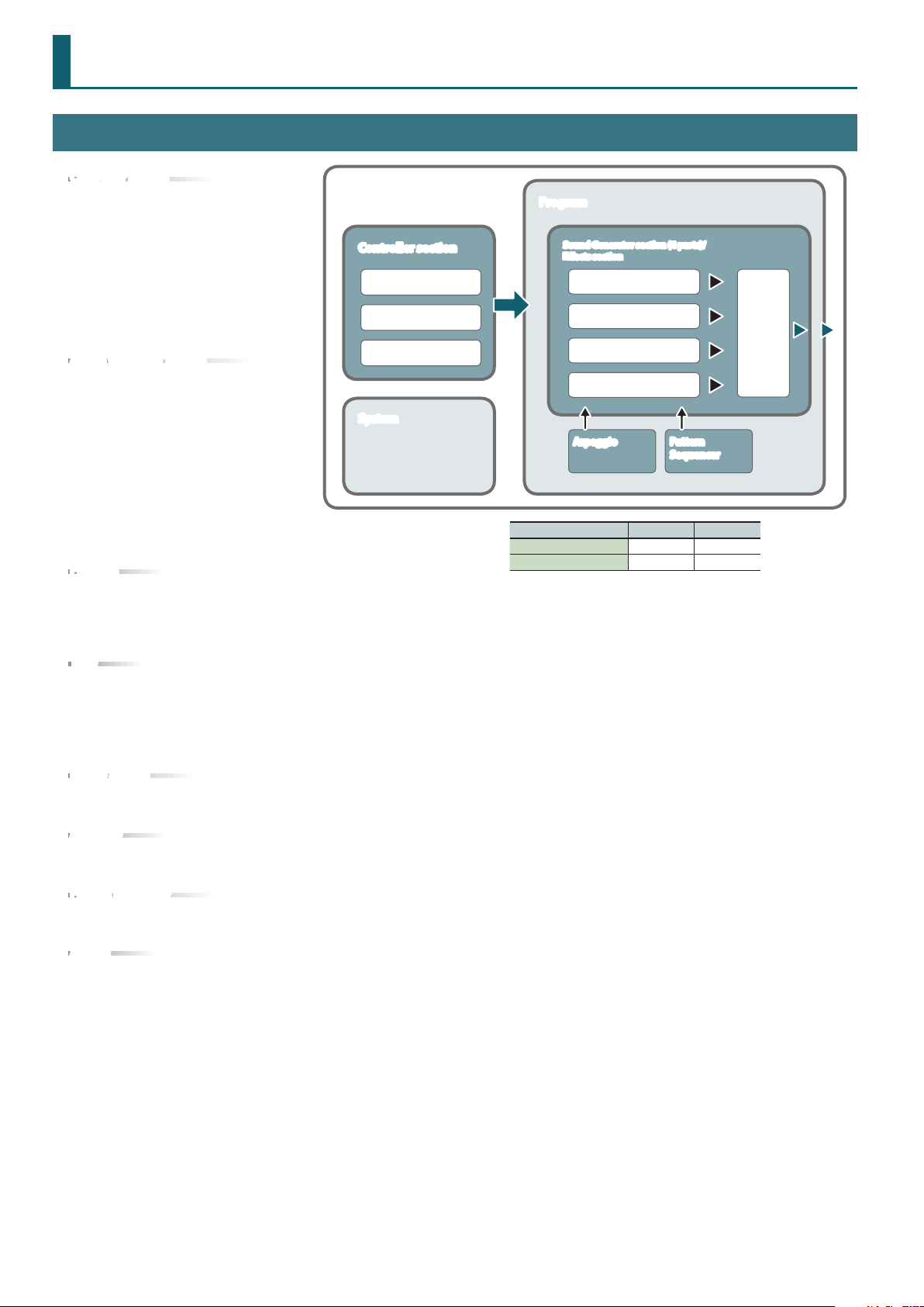
How the JD-Xi Is Structured
Getting Acquainted with the JD-Xi
Controller section
The controller section is what you use for
performing.
For example, a performer’s actions such
as “playing the keyboard” are sent to
the sound generator section, causing it to
produce sound.
The controller section of the JD-Xi consists
of the keyboard, the pitch bend and
modulation wheels, and the panel buttons
and knobs.
Sound generator section
The sound generator section creates the
sound.
In response to the performance data sent
from the controller section, this section
electrically generates the waveform that
is the basis of the sound, and modies the
brightness and loudness to produce an
incredible diversity of sounds.
The JD-Xi’s sound generator section lets
you use the panel knobs and buttons to
instantly change various aspects of the
sound, such as its waveform and pitch, brightness, and loudness.
Program
A program consists of four parts: Digital Synth 1, Digital Synth 2, Drums, and
Analog Synth.
A program you edited can be saved as a user program (64 programs in each bank E–H).
&
“Program Parameters” (p. 10)
Tone
You can select one tone for each part.
For an analog synth tone, the oscillator, sub-oscillator, and lter sections consist of analog circuits.
&
“Analog Synth Tone” (p. 12)
&
“Digital Synth Tone” (p. 15)
&
“Drum Kit” (p. 20)
Eects section
The JD-Xi contains four eect units. Eect settings are saved within each program.
&
“Eects” (p. 26)
Arpeggio
This function automatically plays an arpeggio according to the keys that you hold down. Arpeggio settings are saved within each program.
&
“ARPEGGIO” (p. 29)
Pattern sequencer
This function lets you perform while patterns of several measures play back. You can also create your own original patterns and save them in a
program.
System
This area stores system parameter settings that determine how the JD-Xi operates.
JD-Xi
Controller section
Keyboard
Knobs
Wheels
System
Program
Sound Generator section (4 parts)/
Eects section
Digital Synth 1 part
Digital Synth 2 part
Drums part
Analog Synth part
Arpeggio Pattern
Program Bank Number
Preset program A–D 01–64
User program E–H 01–64
Sequencer
Eects
6
Page 7
How a Tone Is Structured
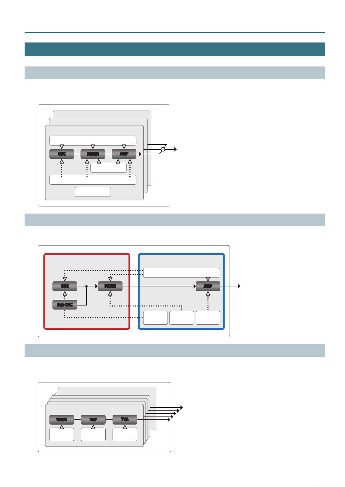
Digital Synth Tone
A digital synth tone contains three sets (Partials 1–3) of OSC (oscillator), FILTER (lter), AMP (amp), and LFO.
Each partial can be turned on/o, allowing you to choose which partials are heard.
&
“Part Output” (p. 10)
PARTIAL 3
PARTIAL 2
PARTIAL 1
LFO
How the JD-Xi Is Structured
OSC FILTER
AFTERTOUCH
MOD LFO
MISC
AMP
Analog Synth Tone
An analog synth tone consists of OSC, Sub OSC, and FILTER implemented by analog circuitry, and a digitally-controlled AMP and LFO.
The OSC, Filter, and AMP each have a separate envelope that can be controlled independently.
Analog circuit
OSC
Sub OSC
(Oct -1/-2)
FILTER AMP
Digital process
Pitch
Envelope
LFO
Filter
Envelope
Amp
Envelope
Drum Kit
A kit contains 26 sets (Partials 1–26) of WAVE, TVF, and TVA.
Each partial has four wave generators.
The 26 partials are assigned to the keyboard (C2–C#4) and can be played as a single instrument.
PARTIAL 26 (C#4)
PARTIAL 1 (C2)
WAVE TVF
Pitch
Envelope
* Each partial has four wave generators.
TVF
Envelope
TVA
TVA
Envelope
7
Page 8
How the JD-Xi Is Structured
JD-Xi Block Diagram (Eect)
WG (Wave Generator)
This selects the PCM waveform that is the basis of the sound, and species how the pitch of the sound changes.
TVF (Time Variant Filter)
This species how the frequency components of the sound change over time.
TVA (Time Variant Amplier)
This creates volume changes and species the pan.
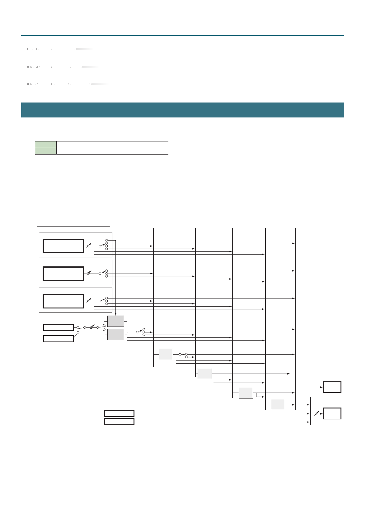
How the Eects Are Structured
As eects, the JD-Xi provides Eect 1, Eect 2, Delay, and Reverb.
For Eect 1 and Eect 2 you can choose from the following eect types.
Eect 1 Distortion, Fuzz, Compressor, Bit Crusher
Eect 2 Flanger, Phaser, Ring Mod, Slicer
* If the Flanger is selected, you can set the Feedback value to 0 and use it as a Chorus.
Each program contains a single set of eect type selection and settings.
For example, a program’s Digital Synth Part 1 cannot have Eect 1 set to Distortion while the same program’s Digital Synth Part 2 has Eect 1 set to
Fuzz.
However as shown below, you can change the connections to specify which eect is used by each part.
Eect block diagram
Digital Synth 2 PART
Digital Synth 1 PART
Digital Synth
Tone
Analog Synth PART
Analog Synth
Tone
Drum PART
Drum Kit
Each Partial
INPUT
MIC
LINE/GUITAR
Part
Level
Part
Level
Part
Level
Input
Level
Part Output
Delay
Send
Reverb Send
Part Output
Delay SendDelay
Reverb Send
Part Output
Delay Send
Reverb Send
Vocoder
Auto Pitch
Click out
USB Audio (Input)
Outputp
Assign
Delay Send
Reverb Send
Eect1
Output
Assign
Delay Send
Reverb Send
Eect2
Delay Send
Reverb Send
Delay
Reverb send
Reverb
Master
Level
OUTPUT
USB Audio
(Output)
PHONES/
OUTPUT
8
Page 9

How the JD-Xi Is Structured
Changing the Connection Destination of Each Part
The Part Output parameter species the eects to which each part is connected (Program Parameter: p. 10).
As the connection destination, you can choose Eect 1, Eect 2, Delay, Reverb, or Direct (no eect applied).
Press the [Eects On/O] button located on the panel of the JD-Xi to specify the eect to which each part is connected. Use the [Part Select] button
to select the part.
You can also specify whether the Eect 1 output is connected to Eect 2 (series connection).
If the Eect 1 Output Assign parameter (p. 26) is set to EFX2, Eect 1 and Eect 2 are connected in series. If it is set to DIR, Eect 1 is not connected to
Eect 2.
For example if you want to use only Distortion on Part 1 and use Flanger on Part 2, set the Eect 1 Output Assign parameter to DIR, set the Part 1 Part
Output (p. 10) to EFX1, and set the Part 2 Part Output to EFX2.
About the Delay Send Level and Reverb Send Level
Delay and Reverb are “send eects.”
The depth of delay and reverb for each part are adjusted by the program parameters “Delay Send Level” and “Reverb Send Level” parameters
(p. 10).
If the Delay Send Level is “0,” no delay is applied even if you turn the panel [Delay] knob.
The panel [Delay] knob aects the Delay Level parameter (p. 26) within the Delay eect.
In the same way, the panel [Reverb] knob aects the Reverb Level parameter (p. 26) within the Reverb eect.
For example, suppose that you want to apply delay to Part 1 when you turn the [Delay] knob, but not to Part 2. In this case, you should raise the Delay
Send Level of Part 1, but set the Delay Send Level of Part 2 to 0.
About Eect Connections for the Drums Part
The Drums part lets you specify the eect connection destination, the Delay Send Level, and the Reverb Send Level for each partial (each instrument
assigned to its own key).
Within the Drum Kit parameters, the Output Assign, Delay Send Level, and Reverb Send Level are set for each partial (each instrument assigned to its
own key) (p. 25).
About Vocoder/AutoPitch Tones
If a Vocoder tone is selected
The currently selected Digital Synth part (Part 1 or Part 2) is connected to the Vocoder eect. You can choose the eect that is connected following
the sound processed by the Vocoder. Within the Vocoder parameters, use the Output Assign parameter to select the connection destination (p. 28).
If an AutoPitch tone is selected
The currently selected Digital Synth part (Part 1 or Part 2) turns o, and the external input (Mic Input or Guitar/Line Input) is connected to AutoPitch.
You can choose the eect that is connected following the sound processed by AutoPitch.
Within the AutoPitch parameters, use the Output Assign parameter to select the connection destination (p. 28).
9
Page 10
Program Parameters
Program Edit
Menu
[Shift] + Cursor [K] [J]
COMMON
MAIN
Parameter
Cursor [K] [J]
Value
Value [-] [+]
Explanation
PROG: COMMON
Tempo 120
Tempo of the program
Tempo MIDI, 5–300
ProgramLevel 0–127 Volume of the program
PROG: MAIN D1
Level 127
PROG: MAIN AN
Level 127
Level 0–127 Volume of each part
Sound Mute OFF, MUTE Temporarily silences (MUTE) each part’s performance, or unmutes it (OFF).
Pan L64–63R
Part Output
Dly Send Lev
(Delay Send Level)
Rev Send Lev
(Reverb Send Level)
Mono/Poly (for the
Analog part, Mono only)
Legato Sw
(Legato Switch)
EFX1, EFX2, DLY, REV,
DIR, KIT
0–127
0–127
MONO, POLY, TONE
OFF, ON, TONE
The Tempo knob adjusts the setting in a range from 60 to 240.
If the SYSTEM parameter Sync Mode is set to SLAVE, only “MIDI” can be selected.
(Since the tempo is synchronized to an external device, it’s not possible to change the tempo
from the JD-Xi.)
PROG: MAIN D2
Level 127
The part that you’re editing is shown in the right of the upper line.
D1/D2
(Digital Synth 1/2), DR (Drums), AN (Analog Synth)
Use the [Part Select] button to switch parts.
Species the stereo position of each part’s sound.
“L64” is far left, “0” is center, and “63R” is far right.
Selects the eect(s) applied to each part.
EFX1: EFX1, EFX2, Delay, and Reverb are applied.
EFX2: EFX2, Delay, and Reverb are applied.
DLY : Delay and Reverb are applied.
REV: Reverb is applied.
DIR: Output without applying any eect.
KIT: Use the settings of each Partial (instrument assigned to its own note) of the Drum Kit.
KIT can be selected only if the Drum part is selected.
If you want to use EFX1 and EFX2 separately for each part, set the Eect 1 parameter Output
Assign to Dir. For details, refer to “Eect block diagram” (p. 8).
You can’t select this parameter if a Vocoder/AutoPitch tone is selected. Make settings within the
Vocoder/AutoPitch parameters (p. 28).
Species the amount of delay applied to each part.
Set this to 0 if you don’t want to apply delay.
You can’t edit this value if Part Output is set to Rev, DIR, or KIT.
Species the amount of reverb applied to each part.
Set this to 0 if you don’t want to apply reverb.
You can’t edit this value if Part Output is set to DIR or KIT.
Choose “MONO” if you want the tone that’s assigned to the part to play monophonically, or
choose “POLY” if you want it to play polyphonically. Choose “TONE” if you want to use the
settings of the tone.
When playing monophonically, you can apply legato. “Legato” is the performance technique in
which notes are smoothly connected from one to the next.
This produces an eect similar to hammering-on or pulling-o when playing a guitar.
Choose “ON” if you want to apply legato, or “OFF” if you don’t. Choose “TONE” if you want to
use the settings of the tone.
PROG: MAIN DR
Level 127
PITCH
10
PROG: PITCH D1
Octave Shift +1
Octave Shift -3–3 Adjusts the pitch of each part in units of an octave (in a range of ±3 octaves).
Coarse Tune -48–+48 Adjusts the pitch of each part in units of a semitone (in a range of ±4 octaves).
Fine Tune -50–+50
Bend Range 0–24, TONE
Porta Sw
(Portamento Switch)
Porta Time
(Portamento Time)
OFF, ON, TONE
0–127, TONE
Adjusts the pitch of each part in units of one cent (in a range of ±50 cents).
One cent is 1/100th of a semitone.
Species in semitone units the amount of pitch change that occurs when you move the pitch
bend wheel (in a range of up to two octaves). The same amount of change occurs when you
move upward or downward.
Choose “TONE” if you want to use the settings of the tone that’s assigned to the part.
Species whether portamento is applied. Choose “ON” if you want portamento to apply, or
“OFF” if not.
Choose “TONE” if you want to use the settings of the tone that’s assigned to the part.
Species the time over which the pitch change occurs when using portamento.
Choose “TONE” if you want to use the settings of the tone that’s assigned to the part.
Page 11
Program Parameters
Menu
[Shift] + Cursor [K] [J]
OFFSET
Parameter
Cursor [K] [J]
Value
Value [-] [+]
Explanation
PROG:OFFSET D1
Cutoff Ofst 0
Cuto Ofst (Cuto Oset) -64–+63 Adjusts the cuto frequency for the tone/drum kit that’s assigned to the part.
Reso Oset
(Resonance Oset)
Attack Ofst (Attack Oset) -64–+63 Adjusts the Attack Time for the tone/drum kit that’s assigned to the part.
Decay Oset -64–+63 Adjusts the Decay Time for the tone/drum kit that’s assigned to the part.
Release Ofst
(Release Oset)
Vibrato Rate -64–+63
Vibrato Depth -64–+63
Vibrato Delay -64–+63
-64–+63 Adjusts the resonance for the tone/drum kit that’s assigned to the part.
-64–+63 Adjusts the Release Time for the tone/drum kit that’s assigned to the part.
Adjusts the vibrato speed of each part (the rate at which the pitch is modulated).
The pitch will be modulated more rapidly for higher settings, and more slowly with lower
settings.
Adjusts the Vibrato Depth (the depth of pitch modulation) for each part.
The pitch will be modulated more greatly for higher settings, and less with lower settings.
Adjusts the time delay until the vibrato (pitch modulation) eect begins. Higher settings will
produce a longer delay time before vibrato begins, while lower settings produce a shorter time.
11
Page 12
Analog Synth Tone
TONE EDIT
Menu
[Shift] + Cursor [K] [J]
COMMON
OSC
Parameter
Cursor [K] [J]
Value
Value [-] [+]
Explanation
TONE: COMMON
Porta SW OFF
Tone Name
Porta Sw
(Portamento Switch)
Porta Time
(Portamento Time)
Legato Sw
(Legato Switch)
Octave Shift -3–+3 Species the octave of the tone.
Bend Range U (Pitch
Bend Range Up)
Bend Range D (Pitch
Bend Range Down)
OFF, ON
0–127
OFF, ON
0–+24
0–-24
Species the name of the tone.
Although you can edit the name and save, this is saved not for individual tones but for the
program.
Species whether portamento is applied. Choose “ON” if you want to apply portamento, or
“OFF” if you don’t.
Species the time over which the pitch change occurs when using portamento. Higher settings
will cause the pitch change to the next note to take more time.
If this is on, pressing a key while the previous key remains held down will cause the pitch to
change to that of the newly pressed key while maintaining the state in which the previous note
was being sounded.
Species the amount of pitch change that occurs when you move the pitch bend wheel all the
way up.
Species the amount of pitch change that occurs when you move the pitch bend wheel all the
way down.
TONE: OSC
Waveform SAW
Waveform SAW, TRI, PW-SQR Selects the waveform.
PWM Depth (Pulse Width
Modulation Depth)
Pulse Width 0–127
Sub OSC OFF, OCT-1, OCT-2
0–127
Species the amount (depth) of LFO that is applied to PW (Pulse Width). If the OSC Wave has
selected PW-SQR, it species the amount of LFO modulation applied to PW (pulse width).
Species the pulse width.
Only if PW-SQR is selected as the OSC Wave, you can specify the width of the square wave’s top
portion (the pulse width) as a percentage of the waveform’s full cycle.
Smaller values produce a narrower pulse, approaching a square wave (pulse width = 50%).
Increasing the value will increase the width, producing a distinctive sound.
Turns the sub-oscillator on/o.
OFF: Sub-oscillator is o
OCT-1: Turns on (mixes) a square wave one octave below.
OCT-2: Turns on (mixes) a square wave two octaves below.
PITCH
FILTER
TONE: PITCH
OSC Pitch 0
OSC Pitch -24–+24 Adjusts the pitch in semitone steps.
OSC Detune -50–+50 Adjusts the pitch in steps of one cent.
Env Attack (Pitch
Envelope Attack Time)
Env Decay (Pitch
Envelope Decay Time)
Env Depth (Pitch
Envelope Depth)
0–127
0–127
-63–+63 Species how much the pitch envelope will aect the pitch.
Species the attack time of the pitch envelope.
This species the time from the moment you press the key until the pitch reaches its highest
(or lowest) point.
Species the decay time of the pitch envelope.
This species the time from the moment the pitch reaches its highest (or lowest) point until it
returns to the pitch of the key you pressed.
TONE: FILTER
Type LPF
Type BYPASS, LPF Species whether to use the analog LPF or not use it (BYPASS).
Cuto 0–127 Species the cuto frequency.
12
Page 13
Analog Synth Tone
Menu
[Shift] + Cursor [K] [J]
FILTER
Parameter
Cursor [K] [J]
Cuto KF
(Cuto Key Follow)
Velo Sens (Filter Envelope
Velocity Sense)
Resonance 0–127 Emphasizes the sound in the region of the lter cuto frequency.
Attack (Filter Envelope
Attack Time)
Decay (Filter Envelope
Decay Time)
Sustain (Filter Envelope
Sustain Level)
Release (Filter Envelope
Release Time)
Depth -63–+63 Species the direction and depth to which the cuto frequency will change.
Value
Value [-] [+]
-100–+100
-63–+63
0–127
0–127
0–127
0–127
Explanation
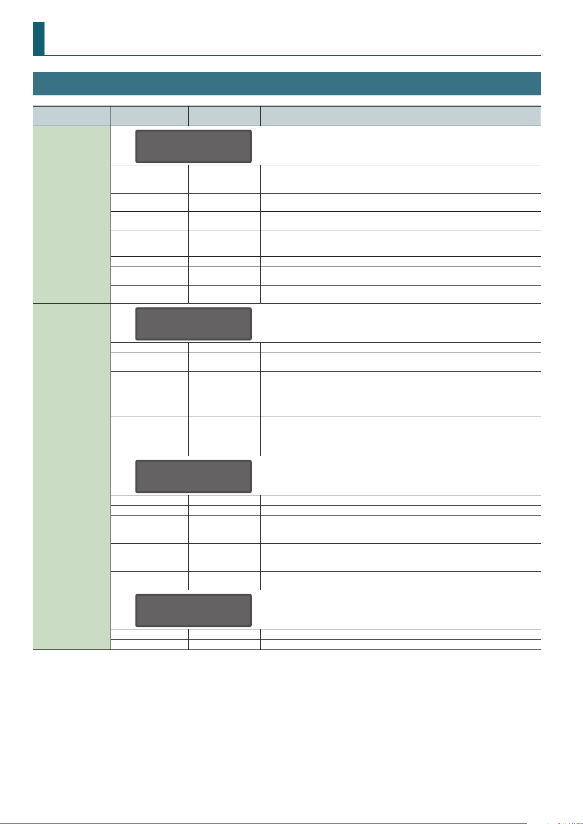
Species how the lter cuto frequency will vary according to the key that you play.
Cuto frequency
(octave)
High
+2
+1
0
-1
-2
C4C3C2 C5 C6
Species how the lter envelope depth will vary according to the strength with which you play
the key.
Species the time from the moment you press the key until the cuto frequency reaches its
highest (or lowest) point.
Species the time from when the cuto frequency reaches its highest (or lowest) point, until it
decays to the sustain level.
Species the cuto frequency that will be maintained from when the attack and decay times
have elapsed until you release the key.
Species the time from when you release the key until the cuto frequency reaches its minimum
value.
+100
+50
0
-50
-100
Value
Low
Key
AMP
TONE: AMP
AMP Level 127
AMP Level 0–127 Volume of the tone
Level V-Sens (Amp Level
Velocity Sense)
Level KF (Amp Level Key
Follow)
Attack (Amp Envelope
Attack Time)
Decay (Amp Envelope
Decay Time)
Sustain (Amp Envelope
Sustain Level)
Release (Amp Envelope
Release Time)
-63–+63 Species how the volume will vary according to the strength with which you play the keyboard.
Specify this if you want to vary the volume according to the position of the key that you play.
-100–+100
0–127
0–127
0–127
0–127
With positive (“+”) settings the volume increases as you play upward from the C4 key (middle C);
with negative (“-”) settings the volume decreases.
Higher values will produce greater change.
Species the attack time of the amp envelope. This species the time from the moment you press
the key until the maximum volume is reached.
Species the decay time of the amp envelope. This species the time from when the maximum
volume is reached, until it decays to the sustain level.
Species the sustain level of the amp envelope. This species the volume level that will be
maintained from when the attack and decay times have elapsed until you release the key.
Species the release time of the amp envelope. This species the time from when you release the
key until the volume reaches its minimum value.
13
Page 14
Analog Synth Tone
Menu
[Shift] + Cursor [K] [J]
LFO
Parameter
Cursor [K] [J]
Value
Value [-] [+]
Explanation
TONE: LFO
Shape TRI
Shape
Rate 0–127 Species the LFO rate when LFO Tempo Sync Sw is OFF.
Tempo Sync OFF, ON If this is ON, the LFO rate can be specied as a note value relative to the tempo.
Sync Note
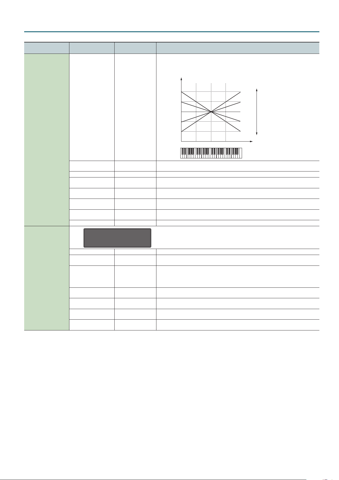
Fade Time 0–127
Key Trigger OFF, ON If this is ON, the LFO cycle will be restarted when you press a key.
Pitch Depth -63–+63 This allows the LFO to modulate the pitch, producing a vibrato eect.
Filter Depth -63–+63 This allows the LFO to modulate the FILTER CUTOFF (cuto frequency), producing a wah eect.
Amp Depth -63–+63 This allows the LFO to modulate the AMP LEVEL (volume), producing a tremolo eect.
Mod Pitch (Modulation
Pitch Depth)
Mod Filter (Modulation
Filter Depth)
Mod Amp (Modulation
Amp Depth)
Mod Rate
(Modulation Rate)
TRI, SIN, SAW, SQR, S&H,
RND
16, 12, 8, 4, 2, 1, 3/4,
2/3, 1/2, 3/8, 1/3, 1/4,
3/16, 1/6, 1/8, 3/32,
1/12, 1/16, 1/24, 1/32
-63–+63
-63–+63
-63–+63
-63–+63
Selects the LFO waveform.
Species the LFO rate when LFO Tempo Sync Sw is ON.
Species the time from when the tone is played until the LFO reaches maximum amplitude.
Fade Time
Species the depth to which the modulation wheel (CC01) can apply modulation to the pitch of
the tone.
Species the depth to which the modulation wheel (CC01) can apply modulation to the FILTER
CUTOFF (cuto frequency).
Species the depth to which the modulation wheel (CC01) can apply modulation to the AMP
LEVEL (volume).
Species how the modulation wheel (CC01) will modify the LFO Rate.
Specify a positive (“+”) setting if you want the LFO Rate to speed up when you increase the
modulation wheel (CC01) value, or specify a negative (“-”) setting if you want the rate to slow
down.
14
Page 15
Digital Synth Tone
TONE EDIT: SuperNATURAL Synth Tone
Each tone has three sets (Partial 1–3) of OSC, FILTER, AMP, and LFO settings.
Menu
[Shift] + Cursor [K] [J]
Parameter
Cursor [K] [J]
Tone Name Species the name of the tone.
Tone Category Selects the tone’s category.
Tone Level 0–127 Adjusts the overall volume of the tone.
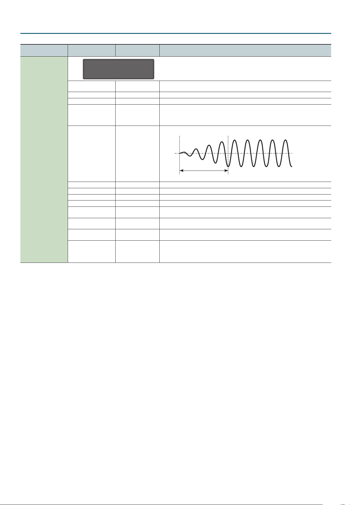
RING Switch OFF, ON
Value
Value [-] [+]
Explanation
Turns ring modulator on/o.
By multiplying partial 1’s OSC and partial 2’s OSC, this creates a complex, metallic-sounding
waveform like that of a bell.
The partial 1’s OSC waveform will change as shown in the illustration, and partial 2’s OSC will be
output with its original waveform.
Setting the partial 1 OSC and the partial 2 OSC to dierent pitches will make the ring modulator
eect more apparent.
Partial 1’s OSC
waveform
Partial 2’s OSC
waveform
Partial 1’s OSC
output waveform
COMMON
If Ring Switch is turned on, the OSC Pulse Width Mod Depth, OSC Pulse Width, and SUPER SAW
Detune of partial 1 and partial 2 cannot be used.
In addition, if an asymmetrical square wave is selected as the OSC waveform, the OSC variation
will be ignored, and there will be a slight dierence in sound compared to the originally selected
waveform.
Wave Shape 0–127
Analog Feel 0–127
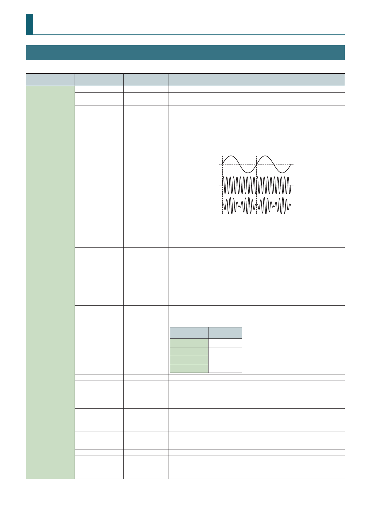
Unison SW
(Unison Switch)
Unison Size 2, 4, 6, 8
Mono/Poly POLY, MONO Species whether notes will sound polyphonically (POLY) or monophonically (MONO).
Legato SW
(Legato Switch)
Porta SW
(Portamento Switch)
Porta Time
(Portamento Time)
Porta Mode
(Portamento Mode)
Octave Shift -3–+3 Species the octave of the tone.
Bend Range U (Pitch
Bend Range Up)
Bend Range D (Pitch
Bend Range Down)
OFF, ON
OFF, ON
OFF, ON Species whether the portamento eect will be applied (ON) or not applied (OFF).
0–127
NORMAL, LEGATO
0–+24
0–-24
Partial 1 will be modulated by the pitch of partial 2. Higher values produce a greater eect.
This has no eect if the partial 1 waveform is PW-SQR or SP-SAW.
Use this to apply “1/f uctuation,” a type of randomness or instability that is present in many
natural systems (such as a babbling brook or whispering breeze) and is perceived as pleasant by
many people.
By applying “1/f uctuation” you can create the natural-sounding instability that is
characteristic of an analog synthesizer.
This layers a single sound.
If the Unison Switch is on, the number of notes layered on one key will change according to the
number of keys you play.
Number of notes assigned to each key when the Unison Switch is on.
Example: If Unison Size is 8
Number of keys
pressed
1 8
2 4 each
3–4 2 each
5–8 1 each
This is valid only if the Mono/Poly parameter is set to “MONO.”
If this is on, pressing a key while the previous key remains held down will cause the pitch to
change to that of the newly pressed key while maintaining the state in which the previous note
was being sounded. This produces an eect similar to hammering-on or pulling-o when playing
a guitar.
Species the time taken for the pitch to change when playing portamento. Higher values
lengthen the time over which the pitch will change to the next note.
NORMAL: Portamento will always be applied.
LEGATO: Portamento will be applied only when you play legato (i.e., when you press the next
key before releasing the previous key).
Species the amount of pitch change that occurs when the pitch bend/modulation lever is
moved all the way to the right.
Species the amount of pitch change that occurs when the pitch bend/modulation lever is
moved all the way to the left.
Number of
notes sounded
15
Page 16
Digital Synth Tone
Menu
[Shift] + Cursor [K] [J]
OSC
PITCH
Parameter
Cursor [K] [J]
TONE:OSC P1
Waveform SP-SAW
Each tone has 3 Partials. The Partial (P1–P3) that is being edited is shown in the upper right of the screen.
Value
Value [-] [+]
Explanation
TONE:OSC P2
Waveform SP-SAW
TONE:OSC P3
Waveform SAW
Selecting partials
You can select and edit the Partial as below.
By pressing the [01] [02] and [03] buttons simultaneously, you can select or edit multiple partials.
For example if [01] [02] and [03] are all on, turning [Cuto] knob will change the cuto frequency of all partials.
Partial 1 select and edit Press the [01] button.
Partial 2 select and edit Press the [02] button.
Partial 3 select and edit Press the [03] button.
Partial 1 turn on Press the [05] button (lit).
Partial 2 turn on Press the [06] button (lit).
Partial 3 turn on Press the [07] button (lit).
SAW
SQR
PW-SQR
Waveform
Variation A, B, C
Wave Number 1–160
PCM Gain -6, 0, +6, +12 [dB]
PWM Depth (Pulse Width
Mod Depth)
Pulse Width 0–127
PW Shift
(Pulse Width Shift)
S-Saw Detune
(Super Saw Detune)
Pitch -24–+24 Adjusts the pitch in semitone steps.
Detune -50–+50 Adjusts the pitch in steps of one cent.
Attack (Pitch Env Attack
Time)
Decay (Pitch Env Decay
Time)
Depth (Pitch Env Depth) -63–+63 This species how much the pitch envelope will aect the pitch.
TRI
SINE
NOISE
SUPER SAW (SP-SAW)
PCM This is a PCM waveform.
0–127
0–127
0–127
0–127
0–127
This waveform contains a sine wave fundamental plus a xed proportion of sine wave harmonics
at all integer multiples of that fundamental.
This waveform contains a sine wave fundamental plus a xed proportion of sine wave harmonics
at odd-numbered multiples of that fundamental.
The overtone structure of this waveform will vary signicantly depending on the width of the
upper portion of the waveform (Pulse Width).
This waveform contains a sine wave fundamental plus a xed proportion of sine wave harmonics
at even-numbered multiples of that fundamental.
This is a sine wave. This is a waveform that produces just a single frequency; it is the basis of all
sound.
This waveform contains all frequencies. It is suitable for percussion instrument sounds or sound
eects.
This produces a tone similar to seven sawtooth waves heard simultaneously. Pitch-shifted sounds
are added to the center sound. It is suitable for strings sounds, and for creating thick sounds.
You can select variations of the currently selected WAVE.
* This has no eect for SP-SAW or PCM.
Selects the PCM waveform.
* This is valid only if PCM is selected for OSC Wave.
Species the gain (amplitude) of the waveform.
The value will change in 6 dB (decibel) steps. Each 6 dB increase doubles the gain.
* This is valid only if PCM is selected for OSC Wave.
Species the amount (depth) of LFO that is applied to PW (Pulse Width).
If the OSC Wave has selected (PW-SQR), you can use this slider to specify the amount of LFO
modulation applied to PW (pulse width).
* If the Ring Switch is on, this has no eect on partials 1 and 2.
Species the pulse width.
Only if (PW-SQR) is selected as the OSC Wave, you can specify the width of the square wave’s top
portion (the pulse width) as a percentage of the waveform’s full cycle.
Smaller values produce a narrower pulse, approaching a square wave (pulse width = 50%).
Increasing the value will increase the width, producing a distinctive sound.
* If the Ring Switch is on, this has no eect on partials 1 and 2.
Shifts the range of change. Normally, you can leave this at 127.
* If the Ring Switch is on, this has no eect on partials 1 and 2.
Species the amount of pitch dierence between the seven sawtooth waves layered within a
single oscillator.
* Higher values will increase the pitch dierence. (OSC Detune applies an equal amount of pitch
dierence between each of the seven sawtooth waves.)
* If the Ring Switch is on, this has no eect on partials 1 and 2.
* This is valid only if SP-SAW is selected for OSC Wave.
Species the attack time of the pitch envelope.
This species the time from the moment you press the key until the pitch reaches its highest
(or lowest) point.
Species the decay time of the pitch envelope.
This species the time from the moment the pitch reaches its highest (or lowest) point until it
returns to the pitch of the key you pressed.
16
Page 17

Digital Synth Tone
Menu
[Shift] + Cursor [K] [J]
FILTER
Parameter
Cursor [K] [J]
Value
Value [-] [+]
Explanation
BYPASS, LPF1, LPF2,
Type
LPF3, LPF4, HPF, BPF,
Selects the type of lter.
PKG
Selects the slope (steepness) of the lter.
For the LPF
Level
Slope (FILTER Slope) -12, -24 [dB]
Cuto 0–127 Species the cuto frequency.
Species how you can make the lter cuto frequency to vary according to the key you play.
Cuto frequency
(OCTAVE)
+2
Cuto KF
(Cuto Key Follow)
-100–+100
+1
0
-1
Frequency
-24 dB
FrequencyCuto
+100
+50
0
-50
-12 dB
High
Value
-2
-100
Low
Velo Sens -63–+63
C4C3C2 C5 C6
Species how you can make the lter envelope depth vary according to the strength with which
you play the key.
Key
Resonance 0–127 Emphasizes the sound in the region of the lter cuto frequency.
Species the time from the
Attack (FILTER Env Attack) 0–127
moment you press the key until
the cuto frequency reaches its
highest (or lowest) point.
Species the time from when
Decay (FILTER Env Decay) 0–127
Sustain (FILTER Env
Sustain)
0–127
the cuto frequency reaches its
highest (or lowest) point, until it
decays to the sustain level.
Species the cuto frequency that
will be maintained from when the
decay time has elapsed until you
release the key.
Cuto
Frequency
Key-on
Species the time from when you
Release (FILTER Env
Release)
0–127
release the key until the cuto
frequency reaches its minimum
value.
Species the direction and depth
Depth (FILTER Env Depth) -63–+63
to which the cuto frequency will
change.
Key-o
DEPTH
Time
17
Page 18

Digital Synth Tone
Menu
[Shift] + Cursor [K] [J]
FILTER HPF Cuto 0–127
AMP
LFO
Parameter
Cursor [K] [J]
Level 0–127 Partial volume.
Level V-Sens -63–+63 Species how the volume will vary according to the strength with which you play the keyboard.
Pan L64–63R Species the stereo position of the partial.
Key Follow
(Amp Level Key Follow)
Attack (AMP Env Attack) 0–127
Decay (AMP Env Decay) 0–127
Sustain (AMP Env Sustain) 0–127
Release
(AMP Env Release)
Shape
Rate 0–127 Species the LFO rate when LFO Tempo Sync Sw is OFF.
Tempo Sync OFF, ON If this is ON, the LFO rate can be specied as a note value relative to the tempo.
Sync Note (LFO Tempo
Sync Note)
Value
Value [-] [+]
-100–+100
0–127
Selects the LFO waveform.
TRI
SIN
SAW
SQR
S&H Sample and Hold (The LFO value will change once each cycle.)
RND Random wave
16, 12, 8, 4, 2, 1, 3/4,
2/3, 1/2, 3/8, 1/3, 1/4,
3/16, 1/6, 1/8, 3/32,
1/12, 1/16, 1/24, 1/32
Explanation
Species the cuto frequency of an independent -6 dB high-pass lter.
BYPASS, LPF, HPF,
-6 dB HPF
Specify this if you want to vary the volume according to the position of the key that you play.
With positive (“+”) settings the volume increases as you play upward from the C4 key (middle C);
with negative (“-”) settings the volume decreases.
Higher values will produce greater change.
Species the time from the
moment you press the key until
the maximum volume is reached.
Species the time from when the
maximum volume is reached, until
it decays to the sustain level.
Species the volume level that
will be maintained from when
the attack and decay times have
elapsed until you release the key.
Species the time from when you
release the key until the volume
reaches its minimum value.
Triangle wave
Sine wave
Sawtooth wave
Square wave
Species the LFO rate when LFO Tempo Sync Sw is ON.
Species the time from when the partial sounds until the LFO reaches its maximum amplitude.
BPF, PKG
Key-on
Key-o
Level
Time
18
Fade Time 0–127
Fade Time
Key Trigger OFF, ON If this is on, the LFO cycle will be restarted when you press a key.
Pitch Depth -63–+63 Allows the LFO to modulate the pitch, producing a vibrato eect.
FILTER Depth -63–+63 Allows the LFO to modulate the FILTER CUTOFF (cuto frequency), producing a wah eect.
AMP Depth -63–+63 Allows the LFO to modulate the AMP LEVEL (volume), producing a tremolo eect.
Pan Depth -63–+63 Allows the LFO to modulate the PAN (stereo position), producing an auto panning eect.
Page 19

Digital Synth Tone
Menu
[Shift] + Cursor [K] [J]
MOD LFO
AFT (AFTERTOUCH)
Parameter
Cursor [K] [J]
Shape
Rate 0–127 Species the LFO rate when ModLFO TempoSyncSw is OFF.
TempoSync OFF, ON If this is ON, the LFO rate can be specied as a note value relative to the tempo.
Sync Note (ModLFO
TempoSyncNote)
Pitch Depth -63–+63 Allows the LFO to modulate the pitch, producing a vibrato eect.
FILTER Depth -63–+63 Allows the LFO to modulate the FILTER CUTOFF (cuto frequency), producing a wah eect.
AMP Depth -63–+63 Allows the LFO to modulate the AMP LEVEL (volume), producing a tremolo eect.
Pan Depth -63–+63 Allows the LFO to modulate the pan (stereo position), producing an auto panning eect.
Rate Control -63–+63
Cuto Sens (Cuto
Aftertouch Sens)
Level Sens (Level
Aftertouch Sens)
Attack Time (Attack Time
Interval Sens)
Release Time (Release
Time Interval Sens)
Porta Time (Portamento
Time Interval Sens)
Value
Value [-] [+]
Selects the MODULATION LFO waveform.
There is an LFO that is always applied to the partial, and a MODULATION LFO for applying modulation with the modulation
controller (CC01).
TRI
SIN
SAW
SQR
S&H Sample and Hold (The LFO value will change once each cycle.)
RND Random wave
16, 12, 8, 4, 2, 1, 3/4,
2/3, 1/2, 3/8, 1/3, 1/4,
3/16, 1/6, 1/8, 3/32,
1/12, 1/16, 1/24, 1/32
-63–+63
-63–+63
0–127
0–127
0–127
Use this to loop the envelope between certain regions during a note-on.
Explanation
Triangle wave
Sine wave
Sawtooth wave
Square wave
Species the LFO rate when ModLFO TempoSyncSw is ON.
Make these settings if you want to change the Modulation LFO Rate when the modulation lever
is operated.
Specify a positive (“+”) setting if you want ModLFO Rate to become faster when you increase
the modulation controller (CC01) value; specify a negative (“-”) setting if you want it to become
slower.
Species how aftertouch pressure will aect the cuto frequency. Specify a positive (“+”) setting
if you want the cuto frequency to rise when the aftertouch message values increase; specify a
negative (“-”) setting if you want the cuto frequency to fall.
Species how aftertouch pressure aects the volume. Specify a positive (“+”) setting if you want
the volume to increase when the aftertouch message values increase; specify a negative (“-”)
setting if you want the volume to decrease.
Shortens the FILTER and AMP Attack Time according to the spacing between note-on events.
Higher values produce a greater eect. With a setting of 0, there will be no eect.
This is eective when you want to play rapid notes using a sound that has a slow attack
(Attack Time).
Shortens the FILTER and AMP Release Time if the interval between one note-on and the next
note-o is brief. Higher values produce a greater eect. With a setting of 0, there will be no eect.
This is eective when you want to play staccato notes using a sound that has a slow release.
Shortens the Portamento Time according to the spacing between note-on events. Higher values
produce a greater eect. With a setting of 0, there will be no eect.
MISC
Mode (Envelope Loop
Mode)
Sync Note (Envelope
Loop Sync Note)
Chroma Porta (Chromatic
Portamento)
Sustain
Attack
OFF The envelope will operate normally.
FREE-RUN
TEMPO-SYNC Species the loop rate as a note value (Sync Note parameter).
Note
OFF, ON If this is turned ON, portamento will operate in semitone steps.
Decay
When the Decay segment has ended, the envelope will return to the Attack. The Attack through
Decay segments will repeat until note-o occurs.
Returns to the Attack at the specied rate. If the Attack+Decay time is shorter than the specied
loop, the sound is maintained at the Sustain Level. If the Attack+Decay time is longer than the
specied loop, the sound returns to the Attack even if the Decay has not completed. This will
continue repeating until note-o occurs.
19
Page 20

Drum Kit
TONE EDIT: PCM Drum Kit
Each kit has 26 sets (Partial 1–26) of WAVE, TVF, and TVA settings.
Each partial has four wave generators. You can assign a dierent note number that will sound each of the 26 partials.
Menu
[Shift] + Cursor [K] [J]
COMMON
Parameter
Cursor [K] [J]
Kit Name
Kit Level 0–127
Assign MULTI, SINGLE
Mute Group OFF, 1–31
Env Mode NO-SUS, SUSTAIN
Bend Range 0–48
Rx Expression OFF, ON
Rx Hold-1 OFF, ON
One Shot Mode OFF, ON
Value
Value [-] [+]
Explanation
Species the name of the drum kit.
You can edit the name and save, but it is saved for the program, not for the individual drum kit.
Sets the volume of the drum kit.
MEMO
The volume of each partial in the drum kit is specied by the TVA Level parameter (p. 24).
The volume of each waveform within a partial is set by the Wave Level parameter (p. 21).
Assign Type sets the way sounds are played when the same key is pressed a number of times.
MULTI: Layer the sound of the same keys. Even with continuous sounds where the sound plays
for an extended time, such as with crash cymbals, the sounds are layered, without previously
played sounds being eliminated.
SINGLE: Only one sound can be played at a time when the same key is pressed. With continuous
sounds where the sound plays for an extended time, the previous sound is stopped when the
following sound is played.
On an actual acoustic drum set, an open hi-hat and a closed hi-hat sound can never occur
simultaneously.
To reproduce the reality of this situation, you can set up a Mute Group.
The Mute Group function allows you to designate two or more drum partials that are not allowed
to sound simultaneously. Up to 31 Mute Groups can be used.
Drum partials that does not belong to any such group should be set to “OFF.”
When a loop waveform is selected, the sound will normally continue as long as the key is
pressed. If you want the sound to decay naturally even if the key remains pressed, set this to
“NO-SUS.”
* If a one-shot type Wave is selected, it will not sustain even if this parameter is set to
“SUSTAIN.”
Species the amount of pitch change in semitones (4 octaves) that will occur when the Pitch
Bend Lever is moved. The amount of change when the lever is tilted is set to the same value for
both left and right sides.
For each drum partial, specify whether MIDI Expression messages will be received (ON), or not
(OFF).
For each drum partial, specify whether MIDI Hold-1 messages will be received (ON), or not (OFF).
NOTE
This has no eect if the Env Mode parameter is set to “NO-SUS.”
The sound will play back until the end of the waveform (or the end of the envelope, whichever
comes rst).
The result will be the same as when the envelope’s Env Mode parameter is set to “NO-SUS.”
WAVE
C 2:WAVE W1
No.L(MONO)137
C 2:WAVE W2
No.L(MONO)458
C 2:WAVE W3
No.L(MONO)458
C 2:WAVE W4
No.L(MONO)458
Each Drum Kit has 26 Partials (26 instruments assigned on keyboard). And each Partial has 4 Wave Generators.
The Partial that is being edited is shown in the upper left of the screen. The Wave (W1–F4) that is being edited is shown in the upper right of the
screen.
You can select and edit the Wave as below.
Wave 1 select and edit Press the [01] button.
Wave 2 select and edit Press the [02] button.
Wave 3 select and edit Press the [03] button.
Wave 4 select and edit Press the [04] button.
Wave 1 turn on Press the [05] button (lit).
Wave 2 turn on Press the [06] button (lit).
Wave 3 turn on Press the [07] button (lit).
Wave 4 turn on Press the [08] button (lit).
20
Page 21

Drum Kit
Menu
[Shift] + Cursor [K] [J]
WAVE
Parameter
Cursor [K] [J]
No.L (Mono)
No.R
Gain -6, 0, +6, +12 [dB]
FXM Switch OFF, ON
FXM Color 1–4
FXM Depth 0–16
Coarse Tune -48–+48
Fine Tune -50–+50
Level 0–127
Pan L64–63R
Random Pan Sw
(Random Pan Switch)
Alter Pan Sw (Alternate
Pan Switch)
WMT Vel Ctrl (WMT
Velocity Control)
Value
Value [-] [+]
OFF, 1–453
OFF, ON
OFF, ON, REVS
OFF, ON, RANDOM
Level
Explanation
Selects the Waves comprising the drum partial. Along with the Wave number, the Wave name
appears at the lower part of the display.
When in monaural mode, only the left side (L) is specied. When in stereo, the right side (R) is also
specied.
Species the gain (amplitude) of the waveform. The value will change in 6 dB (decibel) steps.
Each 6 dB increase doubles the gain.
Sets whether FXM will be used (ON) or not (OFF).
FXM
FXM (Frequency Cross Modulation) uses a specied waveform to apply frequency
modulation to the currently selected waveform, creating complex overtones. This is useful for
creating dramatic sounds or sound eects.
Species how FXM will perform frequency modulation.
Higher settings result in a grainier sound, while lower settings result in a more metallic sound.
Species the depth of the modulation produced by FXM.
NOTE
If Wave Tempo Sync is “ON,” pitch-related settings (p. 22) and FMX-related settings have no
eect.
Adjusts the pitch of the waveform’s sound up or down in semitone steps (+/- 4 octaves).
MEMO
The overall coarse tuning for all of the drum partials is specied by PITCH Coarse Tune (p. 22).
Adjusts the pitch of the waveform’s sound up or down in 1-cent steps (+/-50 cents).
* One cent is 1/100th of a semitone.
MEMO
The overall ne tuning for all of the drum partials is specied by PITCH Fine Tune (p. 22).
Sets the volume of the waveform.
MEMO
The volume of each drum partial is specied by TVA Level (p. 24), and the overall volume of
the entire drum kit is specied by COMMON Kit Level (p. 20).
This species the pan of the waveform.
“L64” is far left, “0” is center, and “63R” is far right.
Use this setting to cause the waveform’s panning to change randomly each time a key is pressed
(ON) or not (OFF).
* To specify the range in which pan is changed, edit Random Pan Depth (p. 24).
This setting causes panning of the waveform to be alternated between left and right each time a
key is pressed.
Set Alter Pan Sw to “ON” to pan the Wave according to the Alter Pan Depth settings, or to
“REVS” when you want the panning reversed.
If you do not want the panning to change each time a key is pressed, set this to “OFF.”
WMT Velocity Control determines whether a dierent drum partial is played (ON) or not (OFF)
depending on the force with which the key is played (velocity).
When set to “RANDOM,” the drum kit’s constituent drum partials will sound randomly,
regardless of any Velocity messages.
WMT
Vel Fade L
(Velo Fade Lower)
Vel Range L
(Velo Range Lower)
Vel Range U
(Velo Range Upper)
Vel Fade U
(Velo Fade Upper)
0–127
1–UPPER
LOWER–127
0–127
Fade Lower
Range Lower Range Upper
Determines what will happen to the tone’s level when the tone is played at a velocity lower than
its specied velocity range. Higher settings produce a more gradual change in volume. If you
want notes played outside the specied key velocity range to not be sounded at all, set this to
“0.”
Sets the lowest velocity at which the waveform will sound. Make these settings when you want
dierent waveforms to sound in response to notes played at dierent strengths.
NOTE
If you attempt to set the lower key velocity above the higher, or the higher key velocity
below the lower, the other setting changes in tandem.
Sets the highest velocity at which the waveform will sound. Make these settings when you want
dierent waveforms to sound in response to notes played at dierent strengths.
This determines what will happen to the tone’s level when the tone is played at a velocity greater
than its specied velocity range.
Higher settings produce a more gradual change in volume.
If you want notes played outside the specied key velocity range to not be sounded at all, set
this to “0.”
Velocity
Fade Upper
21
Page 22

Drum Kit
Menu
[Shift] + Cursor [K] [J]
PITCH
PITCH ENV
Parameter
Cursor [K] [J]
Coarse Tune C-1–G9
Fine Tune -50–+50
Rnd Pch Dpth (Random
Pitch Depth)
Env Depth -12–+12
Env V-Sens -63–+63
Env T1 V-Sens -63–+63
Env T4 V-Sens -63–+63
Env Time 1–4 0–127
Value
Value [-] [+]
0, 1, 2, 3, 4, 5, 6, 7, 8, 9,
10, 20, 30, 40, 50, 60, 70,
80, 90, 100, 200, 300,
400, 500, 600, 700, 800,
900, 1000, 1100, 1200
Explanation
Selects the pitch at which a drum partial sounds.
MEMO
The coarse tune of the waveforms that make up the drum partial is specied by the Wave
Coarse Tune parameter (p. 21).
Adjusts the pitch of the drum partial’s sound up or down in 1-cent steps (+/-50 cents).
* One cent is 1/100th of a semitone.
MEMO
The ne tune of the waveforms that make up the drum partial is specied by the Wave Fine
Tune parameter (p. 21).
Species the width of random pitch deviation that will occur each time a key is pressed. If you do
not want the pitch to change randomly, set this to “0.” These values are in units of cents (1/100th
of a semitone).
Adjusts the eect of the Pitch Envelope. Higher settings will cause the pitch envelope to produce
greater change.
Negative (“-”) settings invert the shape of the envelope.
Keyboard playing dynamics can be used to control the depth of the pitch envelope.
Specify a positive (“+”) setting if you want the pitch envelope to have a greater eect as you play
the key more strongly; specify a negative (“-”) setting if you want the pitch envelope to have less
eect.
Allows keyboard dynamics to aect the Time 1 of the Pitch envelope.
Specify a positive (“+”) setting if you want Time 1 to become faster as you play the key more
strongly; specify a negative (“-”) setting if you want Time 1 to become slower.
Use this parameter when you want key release speed to aect the Time 4 value of the pitch
envelope.
Specify a positive (“+”) setting if you want Time 4 to become faster as you release the key more
quickly; specify a negative (“-”) setting if you want Time 4 to become slower.
Specify the pitch envelope times (Time 1–Time 4).
Higher settings will result in a longer time until the next pitch is reached. (For example, Time 2 is
the time over which the pitch changes from Level 1 to Level 2.)
Specify the pitch envelope levels (Level 0–Level 4).
These specify the amount of pitch change at each point relative to the standard pitch
(Pitch screen) specied by coarse tune (and ne tune). Positive (“+”) settings make the pitch
higher than the standard pitch; negative (“-”) settings make the pitch lower.
T1 T2 T3 T4
Env Level 0–4 -63–+63
Pitch
L0
L1
Key ON Key OFF
L3
L2
T: Time L: Level
Time
L4
22
Page 23

Drum Kit
LPF BPF HPF PKG
Menu
[Shift] + Cursor [K] [J]
TVF
Parameter
Cursor [K] [J]
Filter Type
Cuto 0–127
Value
Value [-] [+]
OFF,
LPF,
BPF,
HPF,
PKG,
LPF2,
LPF3
Explanation
Selects the type of lter. A lter cuts or boosts a specic frequency region to change a sound’s
brightness, thickness, or other qualities.
OFF: The lter is not used.
LPF: Low Pass Filter. Cuts the portion that is above the cuto frequency. By cutting the high-
frequency portion, this gives the sound a milder character. This is the most common lter
used in synthesizers.
BPF: Band Pass Filter. This leaves only the frequencies in the region of the cuto frequency,
and cuts the rest. This can be useful when creating distinctive sounds.
HPF: High Pass Filter. This cuts the frequencies in the region below the cuto frequency. This is
suitable for creating percussive sounds emphasizing their higher ones.
PKG: Peaking Filter. This emphasizes the frequencies in the region of the cuto frequency. This
represents the “resonance” of a drum.
LPF2: Low Pass Filter 2. Although frequency components above the cuto frequency are cut,
the sensitivity of this lter is half that of the LPF. This makes it a comparatively warmer
low pass lter. This lter is good for use with simulated instrument sounds such as the
acoustic piano.
LPF3: Low Pass Filter 3. Although frequency components above the cuto frequency are cut,
the sensitivity of this lter changes according to the Cuto frequency. While this lter
is also good for use with simulated acoustic instrument sounds, the nuance it exhibits
diers from that of the LPF2, even with the same TVF Envelope settings.
LPF HPF BPF PKG
Resonance
Cuto frequency
Cut region
NOTE
If you set “LPF2” or “LPF3,” the setting for the Resonance parameter will be ignored.
Selects the frequency at which the lter begins to have an eect on the waveform’s frequency
components.
With “LPF/LPF2/LPF3” selected for the Filter Type parameter, lower cuto frequency settings
reduce a tone’s upper harmonics for a more rounded, warmer sound. Higher settings make it
sound brighter.
If the Filter Type parameter is set to “BPF,” the cuto frequency setting changes the region of
harmonics that are allowed to sound. This can be useful when creating distinctive sounds.
With “HPF” selected, higher Cuto Frequency settings will reduce lower harmonics to emphasize
just the brighter components of the sound.
With “PKG” selected, the harmonics to be emphasized will vary depending on Cuto Frequency
setting.
Emphasizes the portion of the sound in the region of the cuto frequency, adding character to
the sound. Excessively high settings can produce oscillation, causing the sound to distort.
Resonance 0–127
Cuto V-Crv FIXED, 1–7
Cuto V-Sens -63–+63
High
Frequency
Cuto frequency
Value
Low
Selects one of the following seven curves that determine how keyboard playing dynamics
(velocity) inuence the cuto frequency. Set this to “FIXED” if you don’t want the Cuto
frequency to be aected by the keyboard velocity.
1 2 3 4 5 6 7
Use this parameter when changing the cuto frequency to be applied as a result of changes in
playing velocity.
Specify a positive (“+”) setting if you want the cuto frequency to become higher as you play
more strongly; specify a negative (“-”) setting if you want the cuto frequency to become lower.
23
Page 24

Drum Kit
T1 T2 T3 T4
Menu
[Shift] + Cursor [K] [J]
TVF
Parameter
Cursor [K] [J]
Res V-Sens
(Resonance V-Sns)
Env V-Curve FIXED, 1–7
Env V-Sens -63–+63
Env T1 V-Sens -63–+63
Env T4 V-Sens -63–+63
Env Depth -63–+63
Env Time 1–4 0–127
Value
Value [-] [+]
-63–+63
Explanation
This allows keyboard velocity to modify the amount of Resonance.
Specify a positive (“+”) setting if you want the resonance to increase as you play more strongly;
specify a negative (“-”) setting if you want the resonance to decrease.
Selects one of the following 7 curves that will determine how keyboard playing dynamics will
aect the TVF envelope. Set this to “FIXED” if you don’t want the TVF Envelope to be aected by
the keyboard velocity.
1 2 3 4 5 6 7
Species how keyboard playing dynamics will aect the depth of the TVF envelope.
Specify a positive (“+”) setting if you want the TVF envelope to have a greater eect as you play
more strongly; specify a negative (“-”) setting if you want it to have less eect.
This allows keyboard dynamics to aect the Time 1 of the TVF envelope.
Specify a positive (“+”) setting if you want Time 1 to become faster as you play the key more
strongly; specify a negative (“-”) setting if you want Time 1 to become slower.
The parameter to use when you want key release speed to control the Time 4 value of the TVF
envelope.
Specify a positive (“+”) setting if you want Time 4 to become faster as you release the key more
quickly; specify a negative (“-”) setting if you want Time 4 to become slower.
Species the depth of the TVF envelope. Higher settings will cause the TVF envelope to produce
greater change.
Negative (“-”) settings invert the shape of the envelope.
Specify the TVF envelope times (Time 1–Time 4). Higher settings will lengthen the time until the
next cuto frequency level is reached. (For example, Time 2 is the time over which Level 1 will
change to Level 2.)
Specify the TVF envelope levels (Level 0–Level 4).
These settings specify how the cuto frequency will change at each point, relative to the
standard cuto frequency (the cuto frequency value specied in the TVF screen).
TVF ENV
Env Level 0-4 0–127
Level 0–127
Level V-Curve FIXED, 1–7
TVA
Level V-Sens -63–+63
Pan L64–63R
Rnd Pan Dpth
(Random Pan Depth)
0–63
Cuto
frequency
L0
L2L1 L4
Key ON
T: Time L: Level
Sets the volume of the drum partial. Use this parameter to adjust the volume balance between
drum partials.
L3
Key OFF
Time
MEMO
The volume of the waveform for the drum partial is specied by the Wave Level parameter
(p. 21).
Choose one of the following seven curves to specify how the volume of the drum partial changes
in response to your keyboard playing dynamics.
If you don’t want the volume of the drum partial to change in response to your keyboard
dynamics, choose the “FIXED” setting.
1 2 3 4 5 6 7
Set this when you want the volume of the drum partial to change depending on the force with
which you press the keys.
Specify a positive (“+”) setting if you want the volume of the drum partial to increase as you play
more strongly; specify a negative (“-”) setting if you want the volume to decrease.
Sets the pan for the drum partial. “L64” is far left, “0” is center, and “63R” is far right.
MEMO
Use the Wave Pan parameter (p. 21) to specify the panning of the waveforms that make up
the drum partial.
Use this parameter when you want the stereo location to change randomly each time you press
a key.
Higher settings will produce a greater amount of change.
NOTE
This applies only to waves whose Wave Random Pan Sw parameter (p. 21) is ON.
24
Page 25

Drum Kit
T1 T2 T3 T4
Menu
[Shift] + Cursor [K] [J]
TVA
TVA ENV
Parameter
Cursor [K] [J]
Alt Pan Dpth (Alternate
Pan Depth)
Relative Level -64–+63
Env T1 V-Sens -63–+63
Env T4 V-Sens -63–+63
Env Time 1–4 0–127
Value
Value [-] [+]
L63–63R
Explanation
This setting causes panning to be alternated between left and right each time a key is pressed.
Higher settings will produce a greater amount of change. “L” or “R” settings will reverse the
order in which the pan will alternate between left and right. For example if two drum partials
are set to “L” and “R” respectively, the panning of the two drum partials will alternate each time
they are played.
NOTE
This applies only to waves whose Wave Alter Pan Sw parameter (p. 21) is ON or REVS.
Corrects for the volume of the drum partial.
This parameter is set by the key-based controller system exclusive message. Normally, you
should leave it set to 0.
NOTE
If the drum partial level is set to 127, the volume will not increase beyond that point.
This allows keyboard dynamics to aect the Time 1 of the TVA envelope.
Specify a positive (“+”) setting if you want Time 1 to become faster as you play the key more
strongly; specify a negative (“-”) setting if you want Time 1 to become slower.
The parameter to use when you want key release speed to control the Time 4 value of the TVA
envelope.
Specify a positive (“+”) setting if you want Time 4 to become faster as you release the key more
quickly; specify a negative (“-”) setting if you want Time 4 to become slower.
Specify the TVA envelope times (Time 1–Time 4). Higher settings will lengthen the time until the
next volume level is reached. (For example, Time 2 is the time over which Level 1 will change to
Level 2.)
Specify the TVA envelope levels (Level 1–Level 3).
These settings specify how the volume will change at each point, relative to the standard volume
(the Partial Level value specied in the TVA screen).
OUTPUT
TVA Env Level 1–3 0–127
Output Asgn
(Output Assign)
Output Level 0–127 Species the signal level of each partial.
Dly Send Lev
(Delay Send Level)
Rev Send Lev
(Reverb Send Level)
EFX1, EFX2, DLY, REV,
DIR
0–127 Species the level of the signal sent to the delay for each partial.
0–127 Species the level of the signal sent to the reverb for each partial.
Level
L2
L1
Key ON Key OFF
T: Time L: Level
Species how the sound of each partial will be output.
Time
L3
25
Page 26

Eects
To move between Eect1, Eect2, Delay, and Reverb, hold down the [Shift] button and use the cursor [K] [J] buttons.
Eect Edit
Menu
[Shift] + Cursor [K] [J]
EFFECT1
EFFECT2
Delay
Reverb
Parameter
Cursor [K] [J]
Type
Parameters for each
eect type
Output Asgn
(Output Assign)
Dly Send Lev (Eect1
Delay Send Level)
Rev Send Lev (Eect1
Reverb Send Level)
Type
Parameters for each
eect type
Dly Send Lev (Eect2
Delay Send Level)
Rev Send Lev (Eect2
Reverb Send Level)
Type SINGLE, PAN Selects the type of delay.
Time 0–2600 ms, note Adjusts the delay time.
Tap Time 0–100%
Feedback 0–98% Proportion of delay sound that is returned to the input.
HF Damp (High
Frequency Damp)
Level 0–127 Adjusts the volume of the delay sound.
Rev Send Lev (Delay to
Reverb Send Level)
Type
Time 0–127 Time length of reverberation
HF Damp 200–8000 Hz, BYPASS
Level 0–127 Adjusts the volume of the reverb sound.
Value
Value [-] [+]
00: Thru
01: Distortion
02: Fuzz
03: Compressor
04: Bit Crusher
Edit the parameters for the selected eect type.
&
“Eect Parameters” (p. 26)
DIR, EFX2
0–127 Depth of delay applied to the sound from eect 1.
0–127 Depth of reverb applied to the sound from eect 1.
00: Thru
01: Flanger
02: Phaser
03: Ring Mod
04: Slicer
Edit the parameters for the selected eect type.
&
“Eect Parameters” (p. 26)
0–127 Depth of delay applied to the sound from eect 2.
0–127 Depth of reverb applied to the sound from eect 2.
200–8000 Hz, BYPASS
0–127 Depth of reverb applied to the sound that passes through the delay.
ROOM1, ROOM2,
STAGE1, STAGE2,
HALL1, HALL2
Explanation
Selects the types of eect 1.
Selects the output destination for the sound from eect 1.
DIR: Output to the Output jacks.
EFX2: Output to Eect 2.
If you want to use EFX1 and EFX2 separately for each part, set this parameter to DIR. For details,
refer to the eect block diagram.
Selects the types of eect 2.
Adjusts the delay time of the L-channel relative to the R-channel delay time taken as 100%.
* This can be set if Type = PAN.
Frequency at which to cut the high-frequency portion of the delay sound returned to the input
(BYPASS: no cut).
Species the type of reverb.
Frequency at which to cut the high-frequency portion of the reverb sound.
(BYPASS: no cut)
Eect Parameters
Eect type
Distortion
Fuzz
Compressor
26
Parameter
Cursor [K] [J]
Type 0–5 Selects the type of distortion.
Drive 0–127 Adjusts the depth of distortion.
Presence 0–127 Adjusts the character of the ultra-high-frequency region.
Level 0–127 Adjusts the volume.
Type 0–5 Selects the type of distortion.
Drive 0–127 Adjusts the depth of distortion.
Presence 0–127 Adjusts the character of the ultra-high-frequency region.
Level 0–127 Adjusts the volume.
Threshold 0–127 Level at which compression is applied
Ratio 1: 1–inf: 1 Compression ratio
Attack 0.05–50.0 ms Time from when the input exceeds the Threshold until compression begins
Release 0.05–2000 ms Time from when the input falls below the Threshold until compression is removed
Level 0–127 Adjusts the volume.
Value
Value [-] [+]
Explanation
Page 27

Eects
Eect type
Bit Crusher
Flanger
Phaser
Ring Mod
Slicer
Parameter
Cursor [K] [J]
Rate 0–127 Adjusts the sampling frequency.
Bit 0–127 Adjusts the bit depth.
Filter 0–127 Adjusts the lter depth.
Level 0–127 Adjusts the volume.
Rate 0–127, note Frequency of modulation
Depth 0–127 Depth of modulation
Feedback 0–127 Proportion of the anger sound that is returned to the input
Manual 0–127 Adjusts the basic frequency from which the sound will be modulated.
Balance D100: 0W–D0: 100W Volume balance between the direct sound (D) and the eect sound (W)
Level 0–127 Adjusts the volume.
Rate 0–127, note Adjusts the speed of rotation.
Depth 0–127 Adjusts the depth of the phase eect.
Resonance 0–127 Adjusts the amount of resonance.
Manual 0–127 Adjusts the basic frequency from which the sound will be modulated.
Level 0–127 Adjusts the volume.
Frequency 0–127 Adjusts the frequency at which modulation is applied.
Sens 0–127 Adjusts the amount of frequency modulation applied.
Balance D100: 0W–D0: 100W Volume balance between the direct sound (D) and the eect sound (W)
Level 0–127 Adjusts the volume.
Timing Ptn (Pattern) 0–15 Selects the rhythm pattern by which the sound is sliced.
Rate Note Adjusts the rate at which the sound is sliced.
Attack 0–127 Speed at which the level changes between steps
Trigger Level 0–127
Level 0–127 Adjusts the volume.
Value
Value [-] [+]
Explanation
Species the sensitivity that will trigger playback from the beginning of the selected pattern.
* If you want the Slicer to synchronize to the pattern, set the Trigger Level parameter to 127.
MEMO
When using the Flanger, you can set the Feedback value to 0 and use it as a Chorus eect.
27
Page 28

AutoPitch/Vocoder
AutoPitch
Parameter
Cursor [K] [J]
Level 0–127 Adjusts the volume of the sound that passes through AutoPitch.
Pan L64–63R Adjusts the stereo position of the sound that passes through AutoPitch.
Output Asgn
(Output Assign)
Dly Send Lev
(Delay Send Level)
Rev Send Lev
(Reverb Send Level)
Type
Scale Chromatic, Maj (Min)
Key C–Bm
Value
Value [-] [+]
EFX1, EFX2, DLY, REV, DIR
0–127 Adjusts the amount of delay applied to the sound that passes through AutoPitch.
0–127 Adjusts the amount of reverb applied to the sound that passes through AutoPitch.
Soft, Hard, Electric1,
Electric2
Explanation
Species the output destination of the sound that passes through AutoPitch.
EFX1: Output to Eect 1
EFX2: Output to Eect 2
DLY : Output to Delay
REV: Output to Reverb
DIR: Output without applying an eect
Soft: Corrects the pitch smoothly.
Hard: Corrects the pitch quickly.
Electric 1: Corrects the pitch in a stepwise manner.
Electric 2: Corrects the pitch more strongly than Electric 1. This reproduces the mechanical, step-wise pitch correction
used in pop music.
Chromatic: Corrects the pitch in semitone steps.
Maj (Min): Corrects the pitch to the notes of the scale (Key) you specify.
If the Scale parameter is set to “Maj (Min),” specify the key of the song you’re singing.
For example if the song is in C major, specify “C”; if the song is in A minor, specify “A m.”
Relationship between the key of the song and the key signature (
Major keys
Minor keys
Major keys
and ) of the score
Minor keys
Gender -10–+10
Octave -1, 0, +1 Makes the pitch one octave higher/lower.
Balance D100: 0W–D0: 100W Species the volume balance between the direct sound (D) and the eect sound (W).
Settings in the “-” direction give the voice an increasingly masculine character; settings in the “+” direction give the
voice an increasingly feminine character.
Vocoder
Parameter
Cursor [K] [J]
Tone number 1–256 Selects the instrumental sound.
Level 0–127 Adjusts the output level of the sound that passes through the vocoder.
Pan L64–63R Adjusts the stereo position of the sound that passes through the vocoder.
Output Asgn
(Output Assign)
Dly Send Lev
(Delay Send Level)
Rev Send Lev
(Reverb Send Level)
Envelope Sharp, Soft, Long
Mic Sens 0–127 Species the input sensitivity of the mic.
Synth Level 0–127 Species the input level of the instrumental sound.
Mic Mix Level 0–127
Mic HPF (Mic High Pass
Filter)
Value
Value [-] [+]
EFX1, EFX2, DLY, REV, DIR
0–127 Adjusts the amount of delay that is applied to the sound that passes through the vocoder.
0–127 Adjusts the amount of reverb that is applied to the sound that passes through the vocoder.
BYPASS, 1000–16000 Hz
Explanation
Species the output destination of the sound that passes through the vocoder.
EFX1: Output to Eect 1
EFX2: Output to Eect 2
DLY : Output to Delay
REV: Output to Reverb
DIR: Output without applying an eect
Selects the character of the sound.
SHARP: Emphasizes the human voice.
SOFT: Emphasizes the sound of the instrument.
LONG: Produces a vintage sound with a long decay.
Species the amount of the mic audio passing through the Mic HPF (Mic High Pass Filter) that is added to the output
of the vocoder.
Species the frequency at which the high pass lter (HPF) applied to the mic audio starts to take eect. If this is set to
BYPASS, no lter is applied.
28
Page 29

ARPEGGIO
ARPEGGIO
Parameter
Cursor [K] [J]
(Arpeggio Style) 001–128 This selects the arpeggio’s performance style.
Grid
Duration 30–120%, Full
Motif
Velocity REAL, 1–127
Oct Range -3–+3
Accent 0–100
Value
Value [-] [+]
1/4, 1/8, 1/8L, 1/8H, 1/12,
1/16, 1/16L, 1/16H, 1/24
&
“Selecting
Ascending/Descending
Variations (Motif)”
Explanation
Species the time signature and “swing” of the arpeggio style.
The setting species the note value that one grid unit represents, and the degree of shue (none, light, or heavy).
1/4: Eighth note (two grid sections = one beat)
1/8: Eighth note (two grid sections = one beat)
1/8L: Eighth note shue Light (two grid sections = one beat, with a light shue)
1/8H: Eighth note shue Heavy (two grid sections = one beat, with a heavy shue)
1/12: Eighth note triplet (three grid sections = one beat)
1/16: Sixteenth note (four grid sections = one beat)
1/16L: Sixteenth note shue Light (four grid sections = one beat, with a light shue)
1/16H: Sixteenth note shue Heavy (four grid sections = one beat, with a heavy shue)
1/24: Sixteenth note triplet (six grid sections = one beat)
Species the duration that each note of the arpeggio is sounded.
This determines whether the sounds are played staccato (short and clipped), or tenuto (fully drawn out).
30–120: For example if you specify “30,” each note on the grid (or in the case of tied notes, the last tied note) has a
duration that is 30% of the note value specied by the grid.
Full: Even if the linked grid is not connected with a tie, the same note continues to sound until the point at which the
next new sound is specied.
Species how notes are sounded if you press more keys than the number of notes specied for the arpeggio style.
Refer to “Selecting Ascending/Descending Variations (Motif)” (p. 29).
Species the loudness of the notes that you play.
REAL: If you want the velocity value of each note to depend on how strongly you play the keyboard, set this
parameter to REAL.
1–127: Notes sound at the velocity you specify here, regardless of how strongly you play the keys.
Species the range by which the arpeggio is shifted.
This adds an eect that shifts arpeggios one cycle at a time in octave units (octave range).
You can set the shift range upwards or downwards (up to three octaves up or down).
Species the accent strength for the arpeggio.
With a setting of “100,” the arpeggiated notes will have the velocities that are programmed by the arpeggio style.
With a setting of “0,” all arpeggiated notes will be sounded at a xed velocity.
Selecting Ascending/Descending Variations (Motif)
This selects the method used to play sounds (motif) when you have a greater number of notes than programmed for the Arpeggio Style.
* When the number of keys played is less than the number of notes in the Style, the highest-pitched of the pressed keys is played by default.
Value Explanation
Up (L) Only the lowest of the keys pressed is sounded each time, and the notes play in order from the lowest of the pressed keys.
Up (L&H) Notes from both the lowest and highest pressed keys are sounded each time, and the notes play in order from the lowest of the pressed keys.
Up (_) The notes play in order from the lowest of the pressed keys.
Down (L) Only the lowest of the keys pressed is sounded each time, and the notes play in order from the highest of the pressed keys.
Down (L&H) Notes from both the lowest and highest pressed keys are sounded each time, and the notes play in order from the highest of the pressed keys.
Down (_) The notes play in order from the highest of the pressed keys. No note is played every time.
U/D (L) Notes will be sounded from the lowest to the highest key you press and then back down to the lowest key, with only the lowest key sounded each time.
U/D (L&H)
U/D (_) The notes play in order from the lowest of the pressed keys, and then back again in the reverse order.
Rand (L) Notes will be sounded randomly for the keys you press, with only the lowest key sounded each time.
Rand (_) Only the lowest of the keys pressed is sounded each time, the notes you press will be sounded randomly.
Phrase Pressing just one key will play a phrase based on the pitch of that key. If you press more than one key, the key you press last will be used.
<Example>
Action of a Style starting from the lowest note, “1-2-3-2” when the keys “C-D-E-F-G” are played
Notes from both the lowest and highest pressed keys are sounded each time, and the notes play in order from the lowest of the pressed keys and then back
again in the reverse order.
5 “UP (L)” setting:
C, D, E, D 0 C, E, F, E 0 C, F, G, F (0 repeat)
5 “UP (_)” setting:
C, D, E, D 0 D, E, F, E 0 E, F, G, F (0 repeat)
5 “U/D (L&H)” setting:
C D, G, D 0 C, E, G, E 0 C, F, G, F 0 C, E, G, E (0 repeat)
29
Page 30

Program List
Preset Program
D1 : (Digital Synth Part 1)
D2 : (Digital Synth Part 2)
DR : (Drum Part)
AN : (Analog Synth Part)
A01 Unleash Xi
Genre : Dubstep
D1 : Ah Super Saw Seq
D2 : Scream at me Seq
DR : TR-909 Kit 4
AN : We’reGoingDn
Measure Length : 1
Scale : 1/16
Tempo : 140
MSB : 85
LSB : 64
PC : 1
A02 Dist Seq
Genre : Techno
D1 : Dist Flt TB2 Lead
D2 : LFO ResoPad2 Strings/Pad
DR : Techno Kit 3
AN : SawSweep Bs1
Measure Length : 1
Scale : 1/16
Tempo : 135
MSB : 85
LSB : 64
PC : 2
A03 SPACED
Genre : Tr ap
D1 : SqrTrapPlk 2 Seq
D2 : Unison SynLd Bass
DR : TR-808 Kit 5
AN : Twister 2
Measure Length : 1
Scale : 1/16
Tempo : 71
MSB : 85
LSB : 64
PC : 3
A06 EDM KIDS
Genre : EDM
D1 : HPF Poly 2 Strings/Pad
D2 : Tuned Winds2 FX/Other
DR : TR-808 Kit 6
AN : Buzz Bass
Measure Length : 1
Scale : 1/16
Tempo : 128
MSB : 85
LSB : 64
PC : 6
A07 COME ON BABY
Genre : Tr ap
D1 : Buzz Lead 3 Lead
D2 : Monster Bs 5 Bass
DR : R&B Kit 2
AN : Juxtrans
Measure Length : 1
Scale : 1/32
Tempo : 74
MSB : 85
LSB : 64
PC : 7
A08 Hardstyle 1
Genre : Hardstyle
D1 : OldSchool Ld Bass
D2 : Noise Groove FX/Other
DR : TR-909 Kit 6
AN : ClassicHrdBs
Measure Length : 1
Scale : 1/16
Tempo : 150
MSB : 85
LSB : 64
PC : 8
A11 CARONDO
Genre : Tr ap
D1 : Tekno Lead 5 Lead
D2 : WaveShapeLd2 Lead
DR : TR-808 Kit 8
AN : Springer
Measure Length : 1
Scale : 1/32
Tempo : 70
MSB : 85
LSB : 64
PC : 11
A12 Electro 1
Genre : Electro
D1 : Seq Bass 3 Bass
D2 : Glideator 2 Lead
DR : TR-808 Kit 9
AN : Squeak Bass
Measure Length : 1
Scale : 1/16
Tempo : 124
MSB : 85
LSB : 64
PC : 12
A13 NEUWERK
Genre : Techno
D1 : Sweet 5th 2 Lead
D2 : SqrTrapPlk 3 Seq
DR : Hiphop Kit 4
AN : Sqr Bass 2
Measure Length : 1
Scale : 1/16
Tempo : 130
MSB : 85
LSB : 64
PC : 13
A16 IN DA HOUSE
Genre : House
D1 : SqrFilterBs2 Bass
D2 : Buzz Lead 4 Lead
DR : TR-606 Kit 2
AN : Torque Bass
Measure Length : 1
Scale : 1/16
Tempo : 128
MSB : 85
LSB : 64
PC : 16
A17 Moombahton 1
Genre : Moombahton
D1 : JD RingMod 2 Lead
D2 : Wobble Bs 6 Bass
DR : TR-909 Kit 8
AN : Laser Lead 2
Measure Length : 1
Scale : 1/16
Tempo : 110
MSB : 85
LSB : 64
PC : 17
A18 Seq Phrase 1
Genre : Techno
D1 : FltSweep Pd2 Strings/Pad
D2 : Syn Brass 3 Brass
DR : 707&727 Kit3
AN : Pulse SEQ 1
Measure Length : 1
Scale : 1/16
Tempo : 128
MSB : 85
LSB : 64
PC : 18
A04 GETTIN’CLOSE
Genre : Deep House
D1 : Pluck+SynStr Strings/Pad
D2 : FilterPanPad Bass
DR : 808&7*7 Kit2
AN : Backwards 2
Measure Length : 1
Scale : 1/16
Tempo : 124
MSB : 85
LSB : 64
PC : 4
A05 Trance 1
Genre : Trance
D1 : Pluck Synth2 Seq
D2 : Super Saw 3 Lead
DR : TR-909 Kit 5
AN : Saw Bass 2
Measure Length : 2
Scale : 1/16
Tempo : 135
MSB : 85
LSB : 64
PC : 5
30
A09 DUBBER
Genre : Dubstep
D1 : Wobble Bs 5 Bass
D2 : Noise Snare FX/Other
DR : TR-808 Kit 7
AN : Bacon Bass
Measure Length : 1
Scale : 1/16
Tempo : 84
MSB : 85
LSB : 64
PC : 9
A10 Hip-Hop 1
Genre : Hip-Hop
D1 : DnB Bass 2 Bass
D2 : Harp 2 Keyboard
DR : Hiphop Kit 3
AN : Sqr Lead
Measure Length : 2
Scale : 1/16
Tempo : 100
MSB : 85
LSB : 64
PC : 10
A14 CLIX
Genre : Tr ap
D1 : Tekno Lead 6 Lead
D2 : Monster Bs 6 Bass
DR : TR-909 Kit 7
AN : Fluttertwerk
Measure Length : 1
Scale : 1/16
Tempo : 80
MSB : 85
LSB : 64
PC : 14
A15 PUFFS
Genre : Tr ap
D1 : SqrTrapPlk 4 Seq
D2 : OSC-SyncLd 2 Lead
DR : CR-78 Kit 2
AN : Spitshine
Measure Length : 1
Scale : 1/32
Tempo : 105
MSB : 85
LSB : 64
PC : 15
A19 House 1
Genre : House
D1 : Sync Pad Strings/Pad
D2 : Sqr Bass 1 Bass
DR : EDM Kit 3
AN : Pulse Lead 1
Measure Length : 1
Scale : 1/16
Tempo : 126
MSB : 85
LSB : 64
PC : 19
A20 DRAGON FIRE
Genre : House
D1 : Sonar Pluck2 Seq
D2 : SEQ Saw 2 FX/Other
DR : 909&7*7 Kit2
AN : Snake Glide2
Measure Length : 2
Scale : 1/16
Tempo : 130
MSB : 85
LSB : 64
PC : 20
Page 31

Program List
A21 E-D-M
Genre : EDM
D1 : Seq Bass 4 Bass
D2 : JUNO Sqr Bs2 Bass
DR : TR-808 Kit10
AN : Stream Synth
Measure Length : 1
Scale : 1/16
Tempo : 128
MSB : 85
LSB : 64
PC : 21
A22 EDM 1
Genre : EDM
D1 : SideChainBs3 Bass
D2 : Growl Bass 2 Bass
DR : EDM Kit 4
AN : Sqr SEQ 2
Measure Length : 1
Scale : 1/16
Tempo : 130
MSB : 85
LSB : 64
PC : 22
A23 EDM 2
Genre : EDM
D1 : 5th Stac Bs2 Bass
D2 : EDM Synth 2 Seq
DR : EDM Kit 5
AN : Buzz Saw Ld2
Measure Length : 1
Scale : 1/16
Tempo : 130
MSB : 85
LSB : 64
PC : 23
A26 EDM 4
Genre : EDM
D1 : SuperSaw/SC Seq
D2 : BuzzLd/Legat Lead
DR : EDM Kit 7
AN : SideChainBs1
Measure Length : 2
Scale : 1/16
Tempo : 130
MSB : 85
LSB : 64
PC : 26
A27 EDM 5
Genre : EDM
D1 : Shape Bs/SC Lead
D2 : Buzz Ld/SC Seq
DR : EDM Kit 8
AN : Siren FX 1
Measure Length : 2
Scale : 1/16
Tempo : 130
MSB : 85
LSB : 64
PC : 27
A28 EDM 6
Genre : EDM
D1 : Super Saw 4 Seq
D2 : Fall/Sta&Hol FX/Other
DR : EDM Kit 9
AN : Siren FX 2
Measure Length : 2
Scale : 1/16
Tempo : 130
MSB : 85
LSB : 64
PC : 28
A31 EDM 9
Genre : EDM
D1 : Super Saw 6 Seq
D2 : Trance Key 4 Seq
DR : TR-909 Kit10
AN : Sqr+Sub Bazz
Measure Length : 2
Scale : 1/16
Tempo : 130
MSB : 85
LSB : 64
PC : 31
A32 Big Room 1
Genre : Big Room
D1 : Hatter drop$ Lead
D2 : RiSER 2 Bass
DR : TR-909 Kit11
AN : Kick Sub
Measure Length : 1
Scale : 1/8 Triple
Tempo : 128
MSB : 85
LSB : 64
PC : 32
A33 Big Room 2
Genre : Big Room
D1 : RelaxngBeeps Seq
D2 : Snare Noise Seq
DR : TR-909 Kit12
AN : BigRoom Bass
Measure Length : 1
Scale : 1/16
Tempo : 130
MSB : 85
LSB : 64
PC : 33
A36 Dubstep 1
Genre : Dubstep
D1 : CuttingLead2 Lead
D2 : Wobble Bs 8 Bass
DR : Techno Kit 5
AN : Dubber Bass
Measure Length : 2
Scale : 1/16
Tempo : 140
MSB : 85
LSB : 64
PC : 36
A37 Dubstep 2
Genre : Dubstep
D1 : Grim Grime Bass
D2 : Dirt Lead Lead
DR : EDM Kit 13
AN : Bugs
Measure Length : 1
Scale : 1/16
Tempo : 140
MSB : 85
LSB : 64
PC : 37
A38 SCORPION BIT
Genre : Dubstep
D1 : Sonar Pluck4 Seq
D2 : Sine Lead 2 Lead
DR : EDM Kit 14
AN : Insect 1000
Measure Length : 2
Scale : 1/16
Tempo : 130
MSB : 85
LSB : 64
PC : 38
A24 EDM 3
Genre : EDM
D1 : HPF SweepPd2 Strings/Pad
D2 : Pluck Synth3 Seq
DR : Techno Kit 4
AN : Saw Bass 3
Measure Length : 2
Scale : 1/16
Tempo : 130
MSB : 85
LSB : 64
PC : 24
A25 UPMAN
Genre : EDM
D1 : Trance Key 3 Seq
D2 : SEQ Tri 2 FX/Other
DR : EDM Kit 6
AN : Saw+Sub Bs 2
Measure Length : 2
Scale : 1/16
Tempo : 132
MSB : 85
LSB : 64
PC : 25
A29 EDM 7
Genre : EDM
D1 : Mod Sqr FX/Other
D2 : Super Saw 5 Seq
DR : EDM Kit 10
AN : Buzz/Stacc
Measure Length : 2
Scale : 1/8 Triple
Tempo : 130
MSB : 85
LSB : 64
PC : 29
A30 EDM 8
Genre : EDM
D1 : Sonar Pluck3 Seq
D2 : EDM Synth 3 Seq
DR : TR-909 Kit 9
AN : Saw Buzz 2
Measure Length : 2
Scale : 1/16
Tempo : 130
MSB : 85
LSB : 64
PC : 30
A34 DUBSTOP
Genre : Dubstep
D1 : DistBacking1 Seq
D2 : FlngFallRi Seq
DR : EDM Kit 11
AN : DarkSaw SEQ
Measure Length : 2
Scale : 1/32
Tempo : 130
MSB : 85
LSB : 64
PC : 34
A35 THE ANKH
Genre : Dubstep
D1 : Square Ld 3 Lead
D2 : Wobble Bs 7 Bass
DR : EDM Kit 12
AN : Sick Bass
Measure Length : 2
Scale : 1/16
Tempo : 140
MSB : 85
LSB : 64
PC : 35
A39 PRAWN STAR
Genre : Dubstep
D1 : 106 Bass 4 Bass
D2 : Sine Lead 3 Lead
DR : EDM Kit 15
AN : Phat n Wide
Measure Length : 2
Scale : 1/16
Tempo : 130
MSB : 85
LSB : 64
PC : 39
A40 BENGAL BUS
Genre : Dubstep
D1 : Wobble Bs 9 Bass
D2 : SideChainBs4 Bass
DR : TR-808 Kit11
AN : Bass Mover
Measure Length : 2
Scale : 1/16
Tempo : 130
MSB : 85
LSB : 64
PC : 40
31
Page 32

Program List
A41 Dubstep 3
Genre : Dubstep
D1 : Wah-Wah Strings/Pad
D2 : Harder Pluck Lead
DR : TR-909 Kit13
AN : Fast Wobbles
Measure Length : 1
Scale : 1/16
Tempo : 140
MSB : 85
LSB : 64
PC : 41
A42 Dubstep 4
Genre : Dubstep
D1 : Whoop Echo Seq
D2 : Whoa Lead Lead
DR : TR-909 Kit14
AN : 808 Bass 2
Measure Length : 1
Scale : 1/16
Tempo : 140
MSB : 85
LSB : 64
PC : 42
A43 Dubstep 5
Genre : Dubstep
D1 : Bass Saw Seq
D2 : Arp Lead Lead
DR : TR-909 Kit15
AN : HitThe Floor
Measure Length : 1
Scale : 1/16
Tempo : 140
MSB : 85
LSB : 64
PC : 43
A44 Dubstep 6
Genre : Dubstep
D1 : Tringle Arp Seq
D2 : Sine Bells Seq
DR : TR-909 Kit16
AN : Higher Wob
Measure Length : 1
Scale : 1/16
Tempo : 140
MSB : 85
LSB : 64
PC : 44
A45 Dubstep 7
Genre : Dubstep
D1 : Hip-Hop Lead Lead
D2 : Delay Away Seq
DR : TR-909 Kit17
AN : Crasy Sub
Measure Length : 1
Scale : 1/16
Tempo : 150
MSB : 85
LSB : 64
PC : 45
A46 Dubstep 8
Genre : Dubstep
D1 : Yay Lead Lead
D2 : Wobble Bs 10 Bass
DR : TR-909 Kit18
AN : Saw & Per 2
Measure Length : 2
Scale : 1/16
Tempo : 140
MSB : 85
LSB : 64
PC : 46
A47 Dubstep 9
Genre : Dubstep
D1 : Drty/Vel&Lg1 Bass
D2 : Super Saw 7 Seq
DR : TR-909 Kit19
AN : Saw Buzz 3
Measure Length : 2
Scale : 1/16
Tempo : 140
MSB : 85
LSB : 64
PC : 47
A48 Dubstep 10
Genre : Dubstep
D1 : Dirty /Mod Bass
D2 : Sqr Buzz Ld2 Lead
DR : TR-909 Kit20
AN : Saw&SubBazz
Measure Length : 2
Scale : 1/16
Tempo : 165
MSB : 85
LSB : 64
PC : 48
A49 DRUMSTEP1
Genre : Drumstep
D1 : DirtyFat/Mod Bass
D2 : SawTrap Ld 2 Lead
DR : TR-909 Kit21
AN : Tri Bass 2
Measure Length : 2
Scale : 1/16
Tempo : 175
MSB : 85
LSB : 64
PC : 49
A50 DRUMSTEP2
Genre : Drumstep
D1 : Drty/Vel&Lg2 Bass
D2 : Super Saw 8 Seq
DR : TR-909 Kit22
AN : Tri Bass 3
Measure Length : 2
Scale : 1/16
Tempo : 175
MSB : 85
LSB : 64
PC : 50
A51 Moombahton 2
Genre : Moombahton
D1 : yo son Bass
D2 : Knight Noise Keyboard
DR : TR-808 Kit12
AN : Pulse Lead 2
Measure Length : 1
Scale : 1/16
Tempo : 112
MSB : 85
LSB : 64
PC : 51
A52 ElectroH 1
Genre : Electro House
D1 : Monster Bs 7 Bass
D2 : Reso Bass 6 Bass
DR : EDM Kit 16
AN : Noisy Bass
Measure Length : 2
Scale : 1/16
Tempo : 120
MSB : 85
LSB : 64
PC : 52
A53 ElectroH 2
Genre : Electro House
D1 : ShapeLd /Leg Lead
D2 : Super Saw 9 Seq
DR : EDM Kit 17
AN : Eletro Bass
Measure Length : 2
Scale : 1/16
Tempo : 128
MSB : 85
LSB : 64
PC : 53
A54 ElectroH 3
Genre : Electro House
D1 : Soft Brass 2 Brass
D2 : Ramdom Vox FX/Other
DR : EDM Kit 18
AN : House Bass 2
Measure Length : 2
Scale : 1/16
Tempo : 128
MSB : 85
LSB : 64
PC : 54
A55 Progressive1
Genre : Progressive
D1 : SideChainPd3 Strings/Pad
D2 : Prog Clouds Lead
DR : EDM Kit 19
AN : Fat Sub 1
Measure Length : 1
Scale : 1/16
Tempo : 128
MSB : 85
LSB : 64
PC : 55
House
A56 Progressive2
Genre : Progressive
D1 : PianoTone Strings/Pad
D2 : Revalation 2 Strings/Pad
DR : TR-909 Kit23
AN : House Saw Bs
Measure Length : 2
Scale : 1/16
Tempo : 128
MSB : 85
LSB : 64
PC : 56
House
A57 Progressive3
Genre : Progressive
House
D1 : PlckSyn/Vel1 Seq
D2 : SideChainPd5 Strings/Pad
DR : TR-909 Kit24
AN : Sqr Bass 3
Measure Length : 2
Scale : 1/16
Tempo : 128
MSB : 85
LSB : 64
PC : 57
A58 ACHORDANCE
Genre : Deep House
D1 : ConChord Seq
D2 : Syn Bass 2 Bass
DR : TR-909 Kit25
AN : Soft Bass 2
Measure Length : 1
Scale : 1/16
Tempo : 124
MSB : 85
LSB : 64
PC : 58
A59 STRAIGHT
Genre : Deep House
D1 : StraightChrd Seq
D2 : House Org 3 Keyboard
DR : 808&7*7 Kit3
AN : ClickerBass2
Measure Length : 1
Scale : 1/16
Tempo : 123
MSB : 85
LSB : 64
PC : 59
A60 Deep House 1
Genre : Deep House
D1 : Analog Str 2 Strings/Pad
D2 : Analog Poly5 Seq
DR : 808&909 Kit3
AN : Warm Bass
Measure Length : 2
Scale : 1/16
Tempo : 123
MSB : 85
LSB : 64
PC : 60
32
Page 33

Program List
A61 Deep House 2
Genre : Deep House
D1 : UpBeat Pluck Seq
D2 : Wood Plucks Seq
DR : TR-909 Kit26
AN : Move That Bs
Measure Length : 1
Scale : 1/16
Tempo : 128
MSB : 85
LSB : 64
PC : 61
A62 Deep House 3
Genre : Deep House
D1 : TriangleFeel Seq
D2 : LFO SuperSaw Seq
DR : TR-909 Kit27
AN : The Bass
Measure Length : 1
Scale : 1/16
Tempo : 128
MSB : 85
LSB : 64
PC : 62
A63 Deep House 4
Genre : Deep House
D1 : One Deeper Bass
D2 : 80 Wow Lead
DR : TR-909 Kit28
AN : Fat Sub 2
Measure Length : 1
Scale : 1/16
Tempo : 122
MSB : 85
LSB : 64
PC : 63
B01 House 2
Genre : house
D1 : MeanSuperSaw Seq
D2 : RisngScremer Seq
DR : TR-909 Kit30
AN : Pulled Bass
Measure Length : 1
Scale : 1/16
Tempo : 128
MSB : 85
LSB : 64
PC : 65
B02 CHICAGO
Genre : House
D1 : MinStack Ld2 Lead
D2 : Organ Bass 2 Bass
DR : TR-808 Kit13
AN : Cold Bass
Measure Length : 1
Scale : 1/16
Tempo : 124
MSB : 85
LSB : 64
PC : 66
B03 CLUBBIN’
Genre : House
D1 : S-SawStacLd2 Lead
D2 : Dist TB Sqr2 Lead
DR : TR-808 Kit14
AN : Floor Bass
Measure Length : 1
Scale : 1/16
Tempo : 128
MSB : 85
LSB : 64
PC : 67
B06 TUBULA SWELL
Genre : House
D1 : Dist TB Sqr3 Lead
D2 : LFO Pad 2 Strings/Pad
DR : TR-808 Kit15
AN : Berry Frog
Measure Length : 2
Scale : 1/16
Tempo : 130
MSB : 85
LSB : 64
PC : 70
B07 SUNSET STRIP
Genre : House
D1 : Awakening 2 Strings/Pad
D2 : Organ Bass 3 Bass
DR : Hiphop Kit 5
AN : Underneath
Measure Length : 2
Scale : 1/16
Tempo : 130
MSB : 85
LSB : 64
PC : 71
B08 ORGAN DONOR
Genre : House
D1 : LFO CarvePd2 Strings/Pad
D2 : Organ Bass 4 Bass
DR : Hiphop Kit 6
AN : No. 94 House
Measure Length : 2
Scale : 1/16
Tempo : 130
MSB : 85
LSB : 64
PC : 72
B11 House 4
Genre : House
D1 : Whoop Scream Seq
D2 : Detund S-Saw Lead
DR : TR-909 Kit34
AN : Hit hem Hard
Measure Length : 1
Scale : 1/16
Tempo : 130
MSB : 85
LSB : 64
PC : 75
B12 House 5
Genre : House
D1 : SquaredJumpy Seq
D2 : More Pads Strings/Pad
DR : TR-909 Kit35
AN : Fat Bass
Measure Length : 1
Scale : 1/16
Tempo : 130
MSB : 85
LSB : 64
PC : 76
B13 House 6
Genre : Indie House
D1 : Dark Horn Lead
D2 : Pluck It Bass
DR : 808&909 Kit4
AN : Feedback
Measure Length : 1
Scale : 1/16
Tempo : 112
MSB : 85
LSB : 64
PC : 77
A64 Deep House 5
Genre : Deep House
D1 : SideChainPd2 Strings/Pad
D2 : Porta S-Saw Lead
DR : TR-909 Kit29
AN : Dark Tri Bs
Measure Length : 1
Scale : 1/16
Tempo : 130
MSB : 85
LSB : 64
PC : 64
B04 TRAUMA
Genre : House
D1 : Chow Bass 3 Bass
D2 : Paperclip 2 Seq
DR : TR-909 Kit31
AN : Pumper Bass2
Measure Length : 2
Scale : 1/16
Tempo : 130
MSB : 85
LSB : 64
PC : 68
B05 THE DONK
Genre : House
D1 : JP8 Strings5 Strings/Pad
D2 : Hover Lead 2 Lead
DR : TR-909 Kit32
AN : Slo worn 2
Measure Length : 2
Scale : 1/32
Tempo : 130
MSB : 85
LSB : 64
PC : 69
B09 CHEWY BACCA
Genre : House
D1 : Maker’s 303 Lead
D2 : Saw Lead 2 Lead
DR : 808&7*7 Kit4
AN : Blip
Measure Length : 2
Scale : 1/16
Tempo : 130
MSB : 85
LSB : 64
PC : 73
B10 House 3
Genre : House
D1 : Noise Hit 1 FX/O ther
D2 : Bouncy Pluck Lead
DR : TR-909 Kit33
AN : Up Bass
Measure Length : 1
Scale : 1/16
Tempo : 130
MSB : 85
LSB : 64
PC : 74
B14 PACIFIC+8090
Genre : House
D1 : Lead Sax Brass
D2 : SweepStrings Lead
DR : Hiphop Kit 7
AN : ResoPulseBs2
Measure Length : 1
Scale : 1/16
Tempo : 150
MSB : 85
LSB : 64
PC : 78
B15 House 7
Genre : House
D1 : House Org 4 Keyboard
D2 : Flute 1 Brass
DR : House Kit 2
AN : Sqr+Sub Bs 1
Measure Length : 1
Scale : 1/16
Tempo : 118
MSB : 85
LSB : 64
PC : 79
33
Page 34

Program List
B16 Latin
Genre : Latin
D1 : JD Piano 2 Keyboard
D2 : House Bass 2 Bass
DR : House Kit 3
AN : Porta Tri Ld
Measure Length : 1
Scale : 1/16
Tempo : 118
MSB : 85
LSB : 64
PC : 80
B17 BRISTOL BABY
Genre : Drum & Bass
D1 : Sine Lead 4 Lead
D2 : Noise SEQ 2 FX/Other
DR : Drum&Bs Kit2
AN : Zippers 4
Measure Length : 2
Scale : 1/16
Tempo : 175
MSB : 85
LSB : 64
PC : 81
B18 Drum&Bass 1
Genre : Drum & Bass
D1 : SmallSync Ld Seq
D2 : PchSweep Sin Lead
DR : TR-909 Kit36
AN : OBeat Wob2
Measure Length : 1
Scale : 1/16
Tempo : 140
MSB : 85
LSB : 64
PC : 82
B21 CYCLIC BITE
Genre : Drum & Bass
D1 : Hollow Pad 4 Strings/Pad
D2 : 106 Bass 5 Bass
DR : EDM Kit 22
AN : Squelchy 3
Measure Length : 2
Scale : 1/16
Tempo : 175
MSB : 85
LSB : 64
PC : 85
B22 THE SPEAKER
Genre : Drum & Bass
D1 : Sine Lead 5 Lead
D2 : Bright Pad 2 Strings/Pad
DR : Drum&Bs Kit3
AN : Unsteady Bs
Measure Length : 4
Scale : 1/16
Tempo : 175
MSB : 85
LSB : 64
PC : 86
B23 TURN IT UP
Genre : Drum & Bass
D1 : Detune Bs 2 Bass
D2 : Growl Bass 3 Bass
DR : Hiphop Kit 8
AN : Bo Wop
Measure Length : 2
Scale : 1/16
Tempo : 175
MSB : 85
LSB : 64
PC : 87
B26 Drum&Bass 3
Genre : Drum & Bass
D1 : Vib Wurly 2 Keyboard
D2 : HPF Poly 3 Strings/Pad
DR : Drum&Bs Kit4
AN : Tri Bass 4
Measure Length : 2
Scale : 1/16
Tempo : 170
MSB : 85
LSB : 64
PC : 90
B27 DRUMATIC
Genre : Drum & Bass
D1 : Sweep JD 2 Strings/Pad
D2 : Digital Tp Seq
DR : Drum&Bs Kit5
AN : Deep Bass
Measure Length : 1
Scale : 1/16
Tempo : 160
MSB : 85
LSB : 64
PC : 91
B28 WAR MASTER
Genre : Drum & Bass
D1 : Square Bs 3 Bass
D2 : Vibraphone 2 Keyboard
DR : Drum&Bs Kit6
AN : Tri Bass 5
Measure Length : 2
Scale : 1/16
Tempo : 175
MSB : 85
LSB : 64
PC : 92
B31 WA*SA*BI
Genre : Drum & Bass
D1 : S-Saw Vib Pd Seq
D2 : S-Saw Pad 2 Seq
DR : EDM Kit 23
AN : Saw+Sub Bs 3
Measure Length : 2
Scale : 1/16
Tempo : 185
MSB : 85
LSB : 64
PC : 95
B32 Circadian
Genre : Drum & Bass
D1 : Fall Down Pd FX/Other
D2 : Low Bass 3 Bass
DR : Hiphop Kit10
AN : Saw+Sub SEQ
Measure Length : 2
Scale : 1/32
Tempo : 180
MSB : 85
LSB : 64
PC : 96
B33 Drum&Bass 4
Genre : Drum & Bass
D1 : DnB Bass 3 Bass
D2 : Trance Key 5 Seq
DR : Drum&Bs Kit9
AN : ResoSaw SEQ1
Measure Length : 2
Scale : 1/16
Tempo : 160
MSB : 85
LSB : 64
PC : 97
B19 NOSTALGIA
Genre : Drum & Bass
D1 : Hollow Pad 2 Strings/Pad
D2 : Sqr Bass 2 Bass
DR : EDM Kit 20
AN : Tear Drop 2
Measure Length : 2
Scale : 1/16
Tempo : 175
MSB : 85
LSB : 64
PC : 83
B20 RUBBER BAND
Genre : Drum & Bass
D1 : Hollow Pad 3 Strings/Pad
D2 : MKS-50 Bass2 Bass
DR : EDM Kit 21
AN : Squelchy 2
Measure Length : 2
Scale : 1/16
Tempo : 175
MSB : 85
LSB : 64
PC : 84
B24 ROLLIN!
Genre : Drum & Bass
D1 : Growl Bass 4 Bass
D2 : Growl Bass 5 Keyboard
DR : Hiphop Kit 9
AN : DnB Wobbler2
Measure Length : 2
Scale : 1/16
Tempo : 175
MSB : 85
LSB : 64
PC : 88
B25 Drum&Bass 2
Genre : Drum & Bass
D1 : Alarma Lead
D2 : Ready4u Bass
DR : TR-909 Kit37
AN : Water
Measure Length : 1
Scale : 1/16
Tempo : 180
MSB : 85
LSB : 64
PC : 89
B29 SHACKLES
Genre : Drum & Bass
D1 : Sweet5th SEQ Lead
D2 : HouseResoHit FX/Other
DR : Drum&Bs Kit7
AN : Tri Fall Bs2
Measure Length : 2
Scale : 1/16
Tempo : 180
MSB : 85
LSB : 64
PC : 93
B30 Drumso
Genre : Drum & Bass
D1 : Saw Sweep Pd Strings/Pad
D2 : Dist Sine Bs Bass
DR : Drum&Bs Kit8
AN : Tri Lead 2
Measure Length : 4
Scale : 1/32
Tempo : 192
MSB : 85
LSB : 64
PC : 94
B34 DARK TB
Genre : Techno
D1 : Buzz Lead 5 Lead
D2 : Dist TB Sqr4 Lead
DR : TR-808 Kit16
AN : Pure Comp
Measure Length : 1
Scale : 1/16
Tempo : 128
MSB : 85
LSB : 64
PC : 98
B35 TECHNO LOVE
Genre : Techno
D1 : 106 Bass 6 Bass
D2 : House Bass 3 Bass
DR : TR-808 Kit17
AN : Hamster
Measure Length : 1
Scale : 1/16
Tempo : 128
MSB : 85
LSB : 64
PC : 99
34
Page 35

Program List
B36 HARTFLUR
Genre : Techno
D1 : Dist TB Sqr5 Lead
D2 : Analog Str 3 Strings/Pad
DR : TR-808 Kit18
AN : Fundamental
Measure Length : 1
Scale : 1/16
Tempo : 127
MSB : 85
LSB : 64
PC : 100
B37 CLUBTOOL
Genre : Techno
D1 : Chubby Lead2 Lead
D2 : Tri Stac Ld2 Lead
DR : 808&909 Kit5
AN : Chirp Bass
Measure Length : 1
Scale : 1/16
Tempo : 123
MSB : 85
LSB : 64
PC : 101
B38 CULTURE
Genre : Techno
D1 : MinStack Ld3 Lead
D2 : JD RingMod 3 Lead
DR : 808&7*7 Kit5
AN : Average Bass
Measure Length : 2
Scale : 1/16
Tempo : 125
MSB : 85
LSB : 64
PC : 102
B41 HUUP AMP
Genre : Techno
D1 : LFO Saw SEQ Seq
D2 : Saw+Nz SEQ Seq
DR : 808&909 Kit7
AN : Saw+Sub Bs 4
Measure Length : 1
Scale : 1/16
Tempo : 132
MSB : 85
LSB : 64
PC : 105
B42 Techno 1
Genre : Techno
D1 : SinStackRi Lead
D2 : Saw+Sqr SEQ2 Seq
DR : Techno Kit 7
AN : AcidSaw SEQ2
Measure Length : 1
Scale : 1/16
Tempo : 152
MSB : 85
LSB : 64
PC : 106
B43 STARS
Genre : Techno
D1 : EP SEQ Keyboard
D2 : Trip 2 Mars2 Strings/Pad
DR : 808&7*7 Kit6
AN : Tri Bass 6
Measure Length : 2
Scale : 1/32
Tempo : 128
MSB : 85
LSB : 64
PC : 107
B46 Techno 2
Genre : Techno
D1 : TB Sqr Seq 2 Seq
D2 : S-Saw Pad 3 Seq
DR : Techno Kit 8
AN : Saw Bass 4
Measure Length : 1
Scale : 1/16
Tempo : 132
MSB : 85
LSB : 64
PC : 110
B47 Seq Phrase 2
Genre : Techno
D1 : TB Saw Seq 2 Seq
D2 : Reso S&H Pd2 Strings/Pad
DR : TR-808 Kit20
AN : Pulse+SubBs
Measure Length : 1
Scale : 1/16
Tempo : 130
MSB : 85
LSB : 64
PC : 111
B48 Seq Phrase 3
Genre : Techno
D1 : Seq Bass 5 Bass
D2 : S-SawStacLd3 Lead
DR : Techno Kit 9
AN : Saw SEQ
Measure Length : 1
Scale : 1/16
Tempo : 130
MSB : 85
LSB : 64
PC : 112
B51 AcidHrdstyle
Genre : Acid Hardstyle
D1 : RingMod Lead Lead
D2 : Sweeporama FX/Other
DR : TR-909 Kit40
AN : Tri+SubOSCBs
Measure Length : 1
Scale : 1/16
Tempo : 150
MSB : 85
LSB : 64
PC : 115
B52 TechHouse1
Genre : Tech House
D1 : House Org 5 Keyboard
D2 : Sweet 5th 4 Lead
DR : EDM Kit 24
AN : Tri Bass 8
Measure Length : 1
Scale : 1/16
Tempo : 126
MSB : 85
LSB : 64
PC : 116
B53 TechHouse2
Genre : Tech House
D1 : MinStack Ld4 Lead
D2 : Mute Guitar Keyboard
DR : EDM Kit 25
AN : Tri Bass 9
Measure Length : 1
Scale : 1/16
Tempo : 126
MSB : 85
LSB : 64
PC : 117
B39 IMITATION($)
Genre : Techno
D1 : Saw Backing Strings/Pad
D2 : Tri + Nz SEQ Seq
DR : Techno Kit 6
AN : PortaSawRi
Measure Length : 1
Scale : 1/16
Tempo : 108
MSB : 85
LSB : 64
PC : 103
B40 MOBILE SUIT
Genre : Techno
D1 : Saw+Sqr Wah Seq
D2 : PortaSqrRi Seq
DR : 808&909 Kit6
AN : ResoPulseBs3
Measure Length : 1
Scale : 1/16
Tempo : 102
MSB : 85
LSB : 64
PC : 104
B44 Parabola
Genre : Techno
D1 : Sine SEQ Seq
D2 : Soft Nz Pad Strings/Pad
DR : TR-808 Kit19
AN : Tri Bass 7
Measure Length : 1
Scale : 1/16
Tempo : 125
MSB : 85
LSB : 64
PC : 108
B45 HOTDOGER
Genre : Techno
D1 : Syn Sniper 2 Strings/Pad
D2 : Bend Lead 2 FX/Other
DR : TR-909 Kit38
AN : ResoSaw SEQ2
Measure Length : 2
Scale : 1/16
Tempo : 130
MSB : 85
LSB : 64
PC : 109
B49 Seq Phrase 4
Genre : Techno
D1 : LFO Pad 3 Strings/Pad
D2 : Sweet 5th 3 Lead
DR : 808&909 Kit8
AN : Sqr SEQ 3
Measure Length : 1
Scale : 1/16
Tempo : 130
MSB : 85
LSB : 64
PC : 113
B50 HardHouse
Genre : Techno
D1 : ResoSweepPd1 Strings/Pad
D2 : ResoSaw SEQ1 Seq
DR : TR-909 Kit39
AN : Saw Bass 5
Measure Length : 1
Scale : 1/16
Tempo : 140
MSB : 85
LSB : 64
PC : 114
B54 TechHouse3
Genre : Tech House
D1 : RETROX 139 2 Strings/Pad
D2 : E.Grand 2 Keyboard
DR : EDM Kit 26
AN : Tri Bass 10
Measure Length : 1
Scale : 1/16
Tempo : 126
MSB : 85
LSB : 64
PC : 118
B55 Hardstyle 2
Genre : Hardstyle
D1 : Sliding Lead Lead
D2 : Noise Hit 2 FX/O ther
DR : TR-909 Kit41
AN : SideChainBs2
Measure Length : 1
Scale : 1/16
Tempo : 150
MSB : 85
LSB : 64
PC : 119
35
Page 36

Program List
B56 Hardstyle 3
Genre : Hardstyle
D1 : Synth Crazy Seq
D2 : FallingS-Saw Seq
DR : TR-909 Kit42
AN : HarderKickBs
Measure Length : 1
Scale : 1/16
Tempo : 150
MSB : 85
LSB : 64
PC : 120
B57 Hardstyle 4
Genre : Hardstyle
D1 : SideChainPd4 Strings/Pad
D2 : Lets go fast Lead
DR : TR-909 Kit43
AN : Open Bass
Measure Length : 1
Scale : 1/16
Tempo : 160
MSB : 85
LSB : 64
PC : 121
B58 Hardstyle 5
Genre : Hardstyle
D1 : Ahhh Bass
D2 : Detuner Man Lead
DR : TR-909 Kit44
AN : Big Kick
Measure Length : 1
Scale : 1/16
Tempo : 150
MSB : 85
LSB : 64
PC : 122
B61 Hardcore 2
Genre : Hardcore
D1 : Dist Saw SEQ Seq
D2 : SqrUnisonRif Seq
DR : Hardcore Kit
AN : Dist LFO Bs2
Measure Length : 2
Scale : 1/16
Tempo : 190
MSB : 85
LSB : 64
PC : 125
Techno
B62 Gabbas
Genre : Gabba
D1 : Sqr+Sine Ld Lead
D2 : Pan S-Saw Ld Lead
DR : Gabba Kit
AN : Dist TB Bs 2
Measure Length : 2
Scale : 1/16
Tempo : 202
MSB : 85
LSB : 64
PC : 126
B63 90’S TRANCE
Genre : Trance
D1 : Seq Bass 6 Bass
D2 : House Bass 4 Bass
DR : Techno Kit10
AN : Tranalog
Measure Length : 1
Scale : 1/16
Tempo : 140
MSB : 85
LSB : 64
PC : 127
C01 SHIFTER
Genre : Trance
D1 : 106 Bass 7 Bass
D2 : LFO Pad 4 Strings/Pad
DR : Hiphop Kit11
AN : Trance Bass1
Measure Length : 2
Scale : 1/16
Tempo : 140
MSB : 85
LSB : 65
PC : 1
C02 TEMPER
Genre : Trance
D1 : Filter Bass2 Bass
D2 : SEQ Saw 3 FX/Other
DR : 808&909Kit10
AN : Arpy Synth
Measure Length : 2
Scale : 1/16
Tempo : 140
MSB : 85
LSB : 65
PC : 2
C03 EXILE
Genre : Trance
D1 : 5th Stac Bs3 Bass
D2 : JUNO Sqr Bs3 Bass
DR : 808&909Kit11
AN : Exile Synth
Measure Length : 2
Scale : 1/16
Tempo : 130
MSB : 85
LSB : 65
PC : 3
C06 Trance 3
Genre : Trance
D1 : Dots Seq
D2 : More Bass Bass
DR : TR-909 Kit47
AN : LFO Line
Measure Length : 1
Scale : 1/16
Tempo : 150
MSB : 85
LSB : 65
PC : 6
C07 Trance 4
Genre : Trance
D1 : SuperSaw Hit Seq
D2 : SlidngPtchLd Lead
DR : TR-909 Kit48
AN : More Bass
Measure Length : 1
Scale : 1/16
Tempo : 130
MSB : 85
LSB : 65
PC : 7
C08 NEURAL
Genre : Trance
D1 : Acid SEQ Bass
D2 : SawDetuneSEQ Brass
DR : TR-909 Kit49
AN : DarkSawBass1
Measure Length : 1
Scale : 1/16
Tempo : 136
MSB : 85
LSB : 65
PC : 8
B59 Hardstyle 6
Genre : HardStyle
D1 : UnisonBuzzLd Lead
D2 : SawBuzz Ld 2 Lead
DR : TR-909 Kit45
AN : SawSweep Bs2
Measure Length : 1
Scale : 1/16
Tempo : 150
MSB : 85
LSB : 64
PC : 123
B60 Hardcore 1
Genre : Hardcore
D1 : Sonar Noise FX/Other
D2 : Hover Lead 3 Lead
DR : TR-909 Kit46
AN : Pulse SEQ 2
Measure Length : 2
Scale : 1/16
Tempo : 170
MSB : 85
LSB : 64
PC : 124
Techno
B64 DEEP INSIDE
Genre : Trance
D1 : Buzz Lead 6 Lead
D2 : Soft ResoPd2 Strings/Pad
DR : 808&909 Kit9
AN : Oompf Bass
Measure Length : 2
Scale : 1/16
Tempo : 140
MSB : 85
LSB : 64
PC : 128
C04 TOXIC
Genre : Trance
D1 : Buzz Lead 7 Lead
D2 : Seq Bass 7 Bass
DR : 808&909Kit12
AN : Toxic Bass 2
Measure Length : 2
Scale : 1/16
Tempo : 130
MSB : 85
LSB : 65
PC : 4
C05 Trance 2
Genre : Trance
D1 : Beauty Bass
D2 : Trance Pad Lead
DR : Techno Kit11
AN : Sync Bass
Measure Length : 1
Scale : 1/16
Tempo : 140
MSB : 85
LSB : 65
PC : 5
C09 Trance 5
Genre : Trance
D1 : Pluck /Vel Seq
D2 : SideChainPd6 Seq
DR : TR-909 Kit50
AN : Sqr Bass 4
Measure Length : 2
Scale : 1/16
Tempo : 130
MSB : 85
LSB : 65
PC : 9
C10 Trance 6
Genre : Trance
D1 : S-Saw Pad 4 Seq
D2 : SideChainPd7 Strings/Pad
DR : TR-909 Kit51
AN : Trance Bass2
Measure Length : 2
Scale : 1/16
Tempo : 134
MSB : 85
LSB : 65
PC : 10
36
Page 37

Program List
C11 Trance 7
Genre : Trance
D1 : Clv&Sync/Vel Keyboard
D2 : Sqr Buzz Ld3 Lead
DR : TR-909 Kit52
AN : Psy Bass 4
Measure Length : 2
Scale : 1/16
Tempo : 137
MSB : 85
LSB : 65
PC : 11
C12 Trance 8
Genre : Trance
D1 : BPF Syn Bs 3 Bass
D2 : Super Saw 10 Seq
DR : TR-909 Kit53
AN : Sqr SEQ 4
Measure Length : 1
Scale : 1/16
Tempo : 135
MSB : 85
LSB : 65
PC : 12
C13 DIGI
Genre : Psytrance
D1 : Square Ld 4 Lead
D2 : Reso Bass 7 Bass
DR : Techno Kit12
AN : Psy Bass 5
Measure Length : 2
Scale : 1/16
Tempo : 140
MSB : 85
LSB : 65
PC : 13
C16 R&B
Genre : R&B
D1 : Trem EP 2 Keyboard
D2 : MG Bass 5 Bass
DR : R&B Kit 3
AN : Sine Lead 2
Measure Length : 1
Scale : 1/32
Tempo : 70
MSB : 85
LSB : 65
PC : 16
C17 Hip-Hop 2
Genre : Hip-hop
D1 : D. Mute Gtr2 Keyboard
D2 : Flutter Saw Lead
DR : Hiphop Kit12
AN : Stinger Bass
Measure Length : 1
Scale : 1/16
Tempo : 95
MSB : 85
LSB : 65
PC : 17
C18 Hip-Hop 3
Genre : Hip-hop
D1 : BPF Syn Bs 4 Bass
D2 : Tekno Lead 7 Lead
DR : Hiphop Kit13
AN : Beep Synth
Measure Length : 1
Scale : 1/16
Tempo : 90
MSB : 85
LSB : 65
PC : 18
C21 Hip-Hop 4
Genre : Hip-Hop
D1 : 5th SawLead2 Lead
D2 : Monster Bs 8 Bass
DR : Hiphop Kit14
AN : Sub Bass 2
Measure Length : 2
Scale : 1/16
Tempo : 100
MSB : 85
LSB : 65
PC : 21
C22 SLACK NOIZ
Genre : Hip-Hop
D1 : LFO CarvePd3 Strings/Pad
D2 : JD Piano 3 Keyboard
DR : Hiphop Kit15
AN : Orient Flute
Measure Length : 2
Scale : 1/16
Tempo : 100
MSB : 85
LSB : 65
PC : 22
C23 Hip-Hop 5
Genre : Hip-Hop
D1 : Oldskool Strings/Pad
D2 : Gator Strings/Pad
DR : 808&7*7 Kit8
AN : Robo sweep
Measure Length : 1
Scale : 1/32
Tempo : 75
MSB : 85
LSB : 65
PC : 23
C26 BELFREEZ
Genre : Tr ap
D1 : Fantasy 2 Strings/Pad
D2 : Wide Bass 2 Bass
DR : TR-909 Kit56
AN : Resocut 2
Measure Length : 1
Scale : 1/16
Tempo : 98
MSB : 85
LSB : 65
PC : 26
C27 BAD GIRLZ
Genre : Tr ap
D1 : JD RingMod 4 Lead
D2 : 106 Bass 8 Bass
DR : TR-909 Kit57
AN : Creeper
Measure Length : 1
Scale : 1/16
Tempo : 136
MSB : 85
LSB : 65
PC : 27
C28 DRAGONFLY
Genre : Tr ap
D1 : Awakening 3 Strings/Pad
D2 : 106 Bass 9 Bass
DR : TR-909 Kit58
AN : Sub Pulse
Measure Length : 1
Scale : 1/16
Tempo : 68
MSB : 85
LSB : 65
PC : 28
C14 Psytrance
Genre : Psytrance
D1 : Wobble Bs 11 Bass
D2 : Seq Bass 8 Bass
DR : 808&7*7 Kit7
AN : Psy Bass 6
Measure Length : 2
Scale : 1/16
Tempo : 140
MSB : 85
LSB : 65
PC : 14
C15 VIBRATION
Genre : R&B
D1 : PaperclipHit Seq
D2 : FM E.Piano 3 Keyboard
DR : 707&727 Kit4
AN : ResoSaw Bs 3
Measure Length : 1
Scale : 1/16
Tempo : 82
MSB : 85
LSB : 65
PC : 15
C19 SWAG BABY
Genre : Hip-hop
D1 : Vintager 2 Lead
D2 : SEQ Saw 4 FX/Other
DR : R&B Kit 4
AN : Xi Power Bs
Measure Length : 1
Scale : 1/16
Tempo : 96
MSB : 85
LSB : 65
PC : 19
C20 FLY EAST
Genre : Hip-Hop
D1 : Synth Flute Lead
D2 : Super Saw 11 Seq
DR : TR-808 Kit21
AN : Saw Bass 6
Measure Length : 2
Scale : 1/16
Tempo : 120
MSB : 85
LSB : 65
PC : 20
C24 Trap 1
Genre : Tr ap
D1 : RiSER 3 FX/Other
D2 : Super Saw 12 Lead
DR : TR-909 Kit54
AN : LFBlow
Measure Length : 1
Scale : 1/16
Tempo : 78
MSB : 85
LSB : 65
PC : 24
C25 Trap 2
Genre : Tr ap
D1 : Monster Bs 9 Bass
D2 : EDM Synth 4 Seq
DR : TR-909 Kit55
AN : Celoclip 2
Measure Length : 1
Scale : 1/16
Tempo : 92
MSB : 85
LSB : 65
PC : 25
C29 BURNED
Genre : Tr ap
D1 : HPF Poly 4 Strings/Pad
D2 : Buzz Lead 8 Lead
DR : TR-909 Kit59
AN : Chewy
Measure Length : 1
Scale : 1/16
Tempo : 126
MSB : 85
LSB : 65
PC : 29
C30 Trap 3
Genre : Tr ap
D1 : EDM Synth 5 Seq
D2 : Tri Stac Ld3 Lead
DR : TR-909 Kit60
AN : TriPE
Measure Length : 1
Scale : 1/32
Tempo : 75
MSB : 85
LSB : 65
PC : 30
37
Page 38

Program List
C31 CLAX
Genre : Tr ap
D1 : D-50 Pizz 2 Strings/Pad
D2 : Cincosoft 2 Strings/Pad
DR : TR-909 Kit61
AN : Orange Alert
Measure Length : 1
Scale : 1/16
Tempo : 80
MSB : 85
LSB : 65
PC : 31
C32 CRUTCHES
Genre : Tr ap
D1 : JP8 Strings6 Strings/Pad
D2 : Monster Bs10 Bass
DR : TR-909 Kit62
AN : ZipPhase 2
Measure Length : 1
Scale : 1/32
Tempo : 80
MSB : 85
LSB : 65
PC : 32
C33 Trap 4
Genre : Tr ap
D1 : Buzz Lead 9 Lead
D2 : Psychoscilo2 Strings/Pad
DR : 90’s Kit 2
AN : SawLFO Bass1
Measure Length : 1
Scale : 1/32
Tempo : 74
MSB : 85
LSB : 65
PC : 33
C36 NEEDED
Genre : Tr ap
D1 : Syn Sniper 4 Strings/Pad
D2 : PXZoon 2 Strings/Pad
DR : TR-808 Kit23
AN : Foundry
Measure Length : 1
Scale : 1/16
Tempo : 80
MSB : 85
LSB : 65
PC : 36
C37 THE UNGOOD
Genre : Tr ap
D1 : Trance Key 6 Seq
D2 : Detune Bs 3 Bass
DR : R&B Kit 6
AN : Chatter
Measure Length : 1
Scale : 1/32
Tempo : 96
MSB : 85
LSB : 65
PC : 37
C38 Trap 5
Genre : Tr ap
D1 : Syn Sniper 5 Strings/Pad
D2 : Monster Bs12 Bass
DR : R&B Kit 7
AN : Buzzreed
Measure Length : 1
Scale : 1/32
Tempo : 74
MSB : 85
LSB : 65
PC : 38
C41 Trap 7
Genre : Tr ap
D1 : D-50 Stack 2 Strings/Pad
D2 : LFO CarvePd4 Strings/Pad
DR : TR-808 Kit24
AN : Roomboom
Measure Length : 1
Scale : 1/32
Tempo : 62
MSB : 85
LSB : 65
PC : 41
C42 CLONED
Genre : Tr ap
D1 : Rising SEQ 2 FX/Other
D2 : UnisonSynBs2 Bass
DR : TR-808 Kit25
AN : Icepick
Measure Length : 1
Scale : 1/16
Tempo : 70
MSB : 85
LSB : 65
PC : 42
C43 ANTIHERO
Genre : Tr ap
D1 : SEQ Tri 3 FX/Other
D2 : Syn Vox 2 FX/Other
DR : TR-808 Kit26
AN : SawLFO Bass2
Measure Length : 1
Scale : 1/32
Tempo : 96
MSB : 85
LSB : 65
PC : 43
C46 NEON
Genre : Tr ap
D1 : Kick Bass 3 Bass
D2 : Super Saw 13 Lead
DR : TR-909 Kit64
AN : DarkSawBass2
Measure Length : 1
Scale : 1/32
Tempo : 78
MSB : 85
LSB : 65
PC : 46
C47 BRONZE
Genre : Tr ap
D1 : SideChainBs5 Bass
D2 : Super Saw 14 Lead
DR : TR-909 Kit65
AN : Copper Tone
Measure Length : 1
Scale : 1/16
Tempo : 74
MSB : 85
LSB : 65
PC : 47
C48 FROST
Genre : Tr ap
D1 : FX 4 FX/Other
D2 : Dreaming 2 Strings/Pad
DR : TR-909 Kit66
AN : Popsickle
Measure Length : 1
Scale : 1/32
Tempo : 67
MSB : 85
LSB : 65
PC : 48
C34 BACKFLIP
Genre : Tr ap
D1 : Syn Sniper 3 Strings/Pad
D2 : Monster Bs11 Bass
DR : R&B Kit 5
AN : Hollwcrisp
Measure Length : 1
Scale : 1/32
Tempo : 70
MSB : 85
LSB : 65
PC : 34
C35 DENIED
Genre : Tr ap
D1 : SawBuzz Ld 3 Lead
D2 : SqrTrapPlk 5 Seq
DR : TR-808 Kit22
AN : Stinger 2
Measure Length : 1
Scale : 1/32
Tempo : 76
MSB : 85
LSB : 65
PC : 35
C39 GET THE $
Genre : Tr ap
D1 : OSC-SyncLd 3 Lead
D2 : Ac. Brs Sect Brass
DR : R&B Kit 8
AN : Sus Zap 2
Measure Length : 1
Scale : 1/32
Tempo : 88
MSB : 85
LSB : 65
PC : 39
C40 Trap 6
Genre : Tr ap
D1 : Tekno Lead 8 Lead
D2 : Buzz Lead 10 Lead
DR : R&B Kit 9
AN : Bowouch 2
Measure Length : 1
Scale : 1/32
Tempo : 88
MSB : 85
LSB : 65
PC : 40
C44 CHOKED
Genre : Tr ap
D1 : RETROX 139 3 Strings/Pad
D2 : WaveShapeLd3 Lead
DR : TR-808 Kit27
AN : Tanker
Measure Length : 1
Scale : 1/32
Tempo : 96
MSB : 85
LSB : 65
PC : 44
C45 C-SHOP
Genre : Tr ap
D1 : Kick Bass 2 Bass
D2 : SideChainPd8 Strings/Pad
DR : TR-909 Kit63
AN : Lobotone
Measure Length : 1
Scale : 1/16
Tempo : 76
MSB : 85
LSB : 65
PC : 45
C49 DRILLED
Genre : Tr ap
D1 : Rising SEQ 3 FX/Other
D2 : Super Saw 15 Lead
DR : TR-909 Kit67
AN : Looowww
Measure Length : 1
Scale : 1/32
Tempo : 72
MSB : 85
LSB : 65
PC : 49
C50 BUZZ KILL
Genre : Tr ap
D1 : Rising SEQ 4 FX/Other
D2 : Bend Lead 3 FX/Other
DR : TR-909 Kit68
AN : ToadThroat
Measure Length : 1
Scale : 1/32
Tempo : 76
MSB : 85
LSB : 65
PC : 50
38
Page 39

Program List
C51 TRAPPED
Genre : Tr ap
D1 : Square Ld 5 Lead
D2 : SawTrap Ld 3 Lead
DR : TR-808 Kit28
AN : Spooky Bass1
Measure Length : 2
Scale : 1/16
Tempo : 74
MSB : 85
LSB : 65
PC : 51
C52 PUMP THAT
Genre : Tr ap
D1 : Hover Lead 4 Lead
D2 : Bend Lead 4 FX/Other
DR : 808&909Kit13
AN : HooverSuprt2
Measure Length : 2
Scale : 1/16
Tempo : 80
MSB : 85
LSB : 65
PC : 52
C53 Trap 8
Genre : Tr ap
D1 : Sqr Trap Ld2 Lead
D2 : O’Skool Hit2 FX/Other
DR : Hiphop Kit16
AN : Long & Deep
Measure Length : 2
Scale : 1/16
Tempo : 175
MSB : 85
LSB : 65
PC : 53
C56 Trap 11
Genre : Tr ap
D1 : Susans Horn Lead
D2 : Pluck You Bass
DR : TR-808 Kit29
AN : Little Bot
Measure Length : 1
Scale : 1/16
Tempo : 145
MSB : 85
LSB : 65
PC : 56
C57 LAZER CHEST
Genre : Tr ap
D1 : Super Saw 16 Lead
D2 : Super Saw 17 Lead
DR : TR-808 Kit30
AN : Zippers 5
Measure Length : 2
Scale : 1/32
Tempo : 130
MSB : 85
LSB : 65
PC : 57
C58 Trap 12
Genre : Tr ap
D1 : CuttingLead3 Lead
D2 : Growl Bass 6 Bass
DR : TR-808 Kit31
AN : Reel 2
Measure Length : 2
Scale : 1/16
Tempo : 130
MSB : 85
LSB : 65
PC : 58
C61 Trap 14
Genre : Tr ap
D1 : Sqr Trap Ld3 Lead
D2 : Tekno Lead 9 Lead
DR : EDM Kit 28
AN : Porta Lead 2
Measure Length : 1
Scale : 1/32
Tempo : 107
MSB : 85
LSB : 65
PC : 61
C62 Trap 15
Genre : Tr ap
D1 : SawBuzz Ld 4 Lead
D2 : Super Saw 18 Seq
DR : EDM Kit 29
AN : SirenFX/Mod2
Measure Length : 1
Scale : 1/32
Tempo : 140
MSB : 85
LSB : 65
PC : 62
C63 Trap 16
Genre : Tr ap
D1 : Kick Bass 4 Bass
D2 : Talking Bs 2 Bass
DR : Hiphop Kit17
AN : SqrTrapPluck
Measure Length : 1
Scale : 1/32
Tempo : 70
MSB : 85
LSB : 65
PC : 63
D01 INNER PEACE
Genre : Ambient
D1 : JP8 Strings7 Strings/Pad
D2 : Harp 3 Keyboard
DR : CR-78 Kit 3
AN : Sub Bass 3
Measure Length : 2
Scale : 1/16
Tempo : 120
MSB : 85
LSB : 65
PC : 65
D02 CYGNUS X
Genre : Ambient
D1 : Syn Sniper 6 Strings/Pad
D2 : UnisonSynBs3 Bass
DR : TR-808 Kit33
AN : Cygnus Bass
Measure Length : 1
Scale : 1/16
Tempo : 120
MSB : 85
LSB : 65
PC : 66
D03 DESCENT
Genre : Ambient
D1 : JP8 Strings8 Strings/Pad
D2 : Vibraphone 3 Keyboard
DR : TR-808 Kit34
AN : RelaxationBs
Measure Length : 2
Scale : 1/16
Tempo : 130
MSB : 85
LSB : 65
PC : 67
C54 Trap 9
Genre : Tr ap
D1 : SquaredLFOLd Lead
D2 : Swelling Wow Seq
DR : TR-909 Kit69
AN : Harp Sub
Measure Length : 1
Scale : 1/32
Tempo : 130
MSB : 85
LSB : 65
PC : 54
C55 Trap 10
Genre : Tr ap
D1 : 808 Kick Bs Bass
D2 : Epic Saws Lead
DR : TR-909 Kit70
AN : Siren Hell 2
Measure Length : 1
Scale : 1/32
Tempo : 70
MSB : 85
LSB : 65
PC : 55
C59 TRAPPED DOOR
Genre : Tr ap
D1 : SawTrap Ld 4 Lead
D2 : Growl Bass 7 Bass
DR : TR-808 Kit32
AN : Reel 3
Measure Length : 2
Scale : 1/16
Tempo : 130
MSB : 85
LSB : 65
PC : 59
C60 Trap 13
Genre : Tr ap
D1 : D-50 Stack 3 Strings/Pad
D2 : LFO CarvePd5 Strings/Pad
DR : EDM Kit 27
AN : Fall Synth 2
Measure Length : 1
Scale : 1/32
Tempo : 140
MSB : 85
LSB : 65
PC : 60
C64 Ambient
Genre : Ambient
D1 : Analog Str 4 Strings/Pad
D2 : Seq Bass 9 Bass
DR : Noise Kit 2
AN : Mustard
Measure Length : 1
Scale : 1/16
Tempo : 100
MSB : 85
LSB : 65
PC : 64
D04 CHILL WAVE
Genre : Chill Wave
D1 : Vox Pad/SC FX/Other
D2 : PlckSyn/Vel2 Bass
DR : EDM Kit 30
AN : SawLd&PanDly
Measure Length : 2
Scale : 1/16
Tempo : 90
MSB : 85
LSB : 65
PC : 68
D05 80s Re-Vamp
Genre : 80s Re-Vamp
D1 : UnderTheSea Strings/Pad
D2 : Pluck Me Bass
DR : 808&909Kit14
AN : Saw LFO Lead
Measure Length : 1
Scale : 1/16
Tempo : 100
MSB : 85
LSB : 65
PC : 69
39
Page 40

Program List
D06 Experimental
Genre : Experimental
D1 : Deep Vibes Lead
D2 : Lil guy Bass
DR : TR-909 Kit71
AN : Wobbler sub
Measure Length : 1
Scale : 1/16
Tempo : 150
MSB : 85
LSB : 65
PC : 70
D07 Future Bass
Genre : Future Bass
D1 : Weewoo Seq
D2 : Breathe Lead
DR : TR-909 Kit72
AN : Saw Bass 7
Measure Length : 1
Scale : 1/16
Tempo : 100
MSB : 85
LSB : 65
PC : 71
D08 PULL UP
Genre : Ghetto Funk
D1 : Soft Pad 3 Strings/Pad
D2 : PLS Pad 3 Strings/Pad
DR : 808&7*7 Kit9
AN : Zippers 6
Measure Length : 4
Scale : 1/16
Tempo : 130
MSB : 85
LSB : 65
PC : 72
D11 Electronica2
Genre : Electronica
D1 : Vib Wurly 4 Keyboard
D2 : Psychoscilo3 Strings/Pad
DR : EDM Kit 32
AN : Polta Lead
Measure Length : 2
Scale : 1/16
Tempo : 175
MSB : 85
LSB : 65
PC : 75
D12 Electronic
Genre : Electronic
D1 : Pop Lead Lead
D2 : Saw Pad Strings/Pad
DR : TR-909 Kit73
AN : SideChainHrd
Measure Length : 1
Scale : 1/16
Tempo : 116
MSB : 85
LSB : 65
PC : 76
D13 LATE NIGHT
Genre : Electronic
D1 : Sine Lead 6 Lead
D2 : Brite Str 2 Strings/Pad
DR : CR-78 Kit 4
AN : Spooky Bass2
Measure Length : 1
Scale : 1/16
Tempo : 100
MSB : 85
LSB : 65
PC : 77
D16 TRONIX
Genre : Electronic
D1 : JP8 Strings9 Strings/Pad
D2 : Seq Bass 11 Bass
DR : TR-606 Kit 3
AN : Lava Bass
Measure Length : 1
Scale : 1/16
Tempo : 80
MSB : 85
LSB : 65
PC : 80
D17 CRUISING
Genre : Electronic
D1 : MG Bass 6 Bass
D2 : Analog Str 5 Strings/Pad
DR : Drum&BsKit10
AN : Attack Bass
Measure Length : 1
Scale : 1/16
Tempo : 90
MSB : 85
LSB : 65
PC : 81
D18 Ring Mod
Genre : Electronic
D1 : SinDetuneBs2 Bass
D2 : PluckBacking Seq
DR : TR-808 Kit36
AN : Saw+Sub Lead
Measure Length : 1
Scale : 1/16
Tempo : 90
MSB : 85
LSB : 65
PC : 82
D21 ILLEKTRO
Genre : Electro
D1 : Organ Bass 5 Bass
D2 : JUNO Str 2 Strings/Pad
DR : 808&909Kit15
AN : Roller Bass
Measure Length : 2
Scale : 1/16
Tempo : 140
MSB : 85
LSB : 65
PC : 85
D22 ELECTROFYING
Genre : Electro
D1 : Square Ld 6 Lead
D2 : JP8 Str 10 Strings/Pad
DR : TR-808 Kit38
AN : Drama Lead
Measure Length : 2
Scale : 1/16
Tempo : 140
MSB : 85
LSB : 65
PC : 86
D23 Electro 2
Genre : Electro
D1 : 5th SawLead3 Lead
D2 : Tri Stac Ld4 Lead
DR : 808&909Kit16
AN : PulseOfLife2
Measure Length : 2
Scale : 1/16
Tempo : 140
MSB : 85
LSB : 65
PC : 87
D09 GRIME TIME
Genre : Grime
D1 : Sqr Lead 2 Lead
D2 : D-50 Pizz 3 Strings/Pad
DR : TR-808 Kit35
AN : LFO Skips
Measure Length : 2
Scale : 1/32
Tempo : 135
MSB : 85
LSB : 65
PC : 73
D10 Electronica1
Genre : Electronica
D1 : Vib Wurly 3 Keyboard
D2 : LowBitSample Strings/Pad
DR : EDM Kit 31
AN : Tri Bass 11
Measure Length : 2
Scale : 1/16
Tempo : 132
MSB : 85
LSB : 65
PC : 74
D14 NEW WAVE
Genre : Electronic
D1 : S-SawStacLd4 Lead
D2 : Seq Bass 10 Bass
DR : TR-626 Kit 2
AN : Slime Bass
Measure Length : 1
Scale : 1/16
Tempo : 115
MSB : 85
LSB : 65
PC : 78
D15 70’S SEQ
Genre : Electronic
D1 : FilterEnvBs2 Bass
D2 : JUNO Octavr2 Seq
DR : Noise Kit 3
AN : Soak Bottle
Measure Length : 1
Scale : 1/16
Tempo : 100
MSB : 85
LSB : 65
PC : 79
D19 LoFi
Genre : Electronic
D1 : Flute 2 Brass
D2 : Trem EP 3 Keyboard
DR : 90’s Kit 3
AN : Sqr+Sub Bs 2
Measure Length : 1
Scale : 1/16
Tempo : 90
MSB : 85
LSB : 65
PC : 83
D20 DUCKS ATTACK
Genre : Electro
D1 : Dist Flt TB3 Lead
D2 : Seq Bass 12 Bass
DR : TR-808 Kit37
AN : Gargle
Measure Length : 1
Scale : 1/16
Tempo : 124
MSB : 85
LSB : 65
PC : 84
D24 Electro 3
Genre : Electro
D1 : Groovy Pluck Seq
D2 : High Clicks Seq
DR : TR-909 Kit74
AN : Sawed Out
Measure Length : 1
Scale : 1/16
Tempo : 114
MSB : 85
LSB : 65
PC : 88
D25 Electro 4
Genre : Electro
D1 : Stab it Lead
D2 : Old whip Bass
DR : TR-909 Kit75
AN : Afro Crack
Measure Length : 1
Scale : 1/16
Tempo : 128
MSB : 85
LSB : 65
PC : 89
40
Page 41

Program List
D26 Electro 5
Genre : Electro
D1 : Crusty Ba$$ Lead
D2 : Laserhead FX/Other
DR : TR-909 Kit76
AN : Init Grime
Measure Length : 1
Scale : 1/16
Tempo : 128
MSB : 85
LSB : 65
PC : 90
D27 Electro 6
Genre : Electro
D1 : Big Plucker Bass
D2 : Creeper Lead
DR : TR-909 Kit77
AN : Guitar Sweep
Measure Length : 1
Scale : 1/16
Tempo : 130
MSB : 85
LSB : 65
PC : 91
D28 Electro 7
Genre : Electro
D1 : Metallic Aci Lead
D2 : Throw Up Lead
DR : TR-808 Kit39
AN : Crying Alien
Measure Length : 1
Scale : 1/16
Tempo : 126
MSB : 85
LSB : 65
PC : 92
D31 FIRE FIGHT
Genre : Breakbeat
D1 : SEQ 5 Seq
D2 : Low Bass 4 Bass
DR : Hiphop Kit19
AN : Fat as That2
Measure Length : 2
Scale : 1/16
Tempo : 140
MSB : 85
LSB : 65
PC : 95
D32 END OF NIGHT
Genre : Breakbeat
D1 : JD Piano 4 Keyboard
D2 : Detune Bs 4 Bass
DR : Hiphop Kit20
AN : PWM Basic
Measure Length : 2
Scale : 1/16
Tempo : 140
MSB : 85
LSB : 65
PC : 96
D33 LOCK UP!
Genre : Garage
D1 : Sine Lead 7 Lead
D2 : D-50 Pizz 4 Strings/Pad
DR : TR-909 Kit78
AN : Knat Squat
Measure Length : 2
Scale : 1/16
Tempo : 140
MSB : 85
LSB : 65
PC : 97
D36 GOPHER GOLD
Genre : Garage
D1 : Sine Lead 8 Lead
D2 : Sine Lead 9 Lead
DR : TR-909 Kit81
AN : Slurry Bass
Measure Length : 2
Scale : 1/16
Tempo : 140
MSB : 85
LSB : 65
PC : 100
D37 Chiptune 1
Genre : Chiptune
D1 : 8bitSqr /Mod Bass
D2 : EDM Synth 6 Seq
DR : EDM Kit 33
AN : 8bitBass/Leg
Measure Length : 2
Scale : 1/16
Tempo : 170
MSB : 85
LSB : 65
PC : 101
D38 Chiptune 2
Genre : Chiptune
D1 : 8bit Per Seq
D2 : DirtyBass/SC Seq
DR : EDM Kit 34
AN : Bleep Bass
Measure Length : 2
Scale : 1/16
Tempo : 128
MSB : 85
LSB : 65
PC : 102
D41 90sVideoGame
Genre : Chiptune
D1 : Dist Guitar2 Keyboard
D2 : 4Op FM Bass2 Bass
DR : TR-626 Kit 3
AN : Pulse Lead 3
Measure Length : 2
Scale : 1/16
Tempo : 150
MSB : 85
LSB : 65
PC : 105
D42 Synth Pop
Genre : Synth Pop
D1 : Saw+S-SawSEQ Strings/Pad
D2 : ResoSweepPd2 Seq
DR : Techno Kit14
AN : Saw Bass 8
Measure Length : 2
Scale : 1/16
Tempo : 125
MSB : 85
LSB : 65
PC : 106
D43 TECHOtooOLD
Genre : Synth Pop
D1 : Saw+S-Saw Pd Bass
D2 : Synth Snare FX/Other
DR : TR-808 Kit40
AN : Analog Kick2
Measure Length : 2
Scale : 1/16
Tempo : 130
MSB : 85
LSB : 65
PC : 107
D29 Gio-Gio-MRD
Genre : Electro
D1 : Pulse Synth Seq
D2 : S-Saw Pad 5 Strings/Pad
DR : Techno Kit13
AN : Pulse Bass 2
Measure Length : 1
Scale : 1/16
Tempo : 136
MSB : 85
LSB : 65
PC : 93
D30 MAINLINE
Genre : Breakbeat
D1 : PLS Pad 4 Strings/Pad
D2 : House Org 6 Keyboard
DR : Hiphop Kit18
AN : Drift & Grit
Measure Length : 2
Scale : 1/16
Tempo : 140
MSB : 85
LSB : 65
PC : 94
D34 MINISTRY
Genre : Garage
D1 : Hollow Pad 5 Strings/Pad
D2 : JD Piano 5 Keyboard
DR : TR-909 Kit79
AN : ReeceClassic
Measure Length : 2
Scale : 1/16
Tempo : 140
MSB : 85
LSB : 65
PC : 98
D35 LORNA’s VIBE
Genre : Garage
D1 : Revalation 3 Strings/Pad
D2 : JD Piano 6 Keyboard
DR : TR-909 Kit80
AN : Bouncy Bass2
Measure Length : 2
Scale : 1/16
Tempo : 140
MSB : 85
LSB : 65
PC : 99
D39 9BIT
Genre : Chiptune
D1 : Sqr Backing Seq
D2 : Sqr SEQ Seq
DR : ElectricKit1
AN : Tri Bass 12
Measure Length : 2
Scale : 1/16
Tempo : 130
MSB : 85
LSB : 65
PC : 103
D40 STRIKE
Genre : Chiptune
D1 : Tri Bass 2 Bass
D2 : Sqr+Pls Pad Strings/Pad
DR : 707&727 Kit5
AN : Sqr SEQ 5
Measure Length : 2
Scale : 1/16
Tempo : 175
MSB : 85
LSB : 65
PC : 104
D44 Idol Error
Genre : Synth Pop
D1 : DistBacking2 Seq
D2 : Saw+Sqr Ri Seq
DR : Techno Kit15
AN : ResoSaw Bs 4
Measure Length : 1
Scale : 1/16
Tempo : 136
MSB : 85
LSB : 65
PC : 108
D45 Fancy’70s
Genre : Synth Pop
D1 : LFO S-SawSyn Strings/Pad
D2 : Saw+Sqr SEQ1 Seq
DR : CR-78 Kit 5
AN : Tri+Sub SEQ
Measure Length : 1
Scale : 1/16
Tempo : 118
MSB : 85
LSB : 65
PC : 109
41
Page 42

Program List
EE
D46 1024K
Genre : Synth Pop
D1 : ResoSaw SEQ2 Seq
D2 : S&H Reso Pad Strings/Pad
DR : ElectricKit2
AN : Pulse Bass 3
Measure Length : 2
Scale : 1/16
Tempo : 100
MSB : 85
LSB : 65
PC : 110
D51 Pop 2
Genre : Pop
D1 : PortaSaw Ld2 Lead
D2 : Tekno Lead10 Lead
DR : EDM Kit 35
AN : Xi Saw
Measure Length : 1
Scale : 1/16
Tempo : 95
MSB : 85
LSB : 65
PC : 115
D56 CHANCE!
Genre : Pop
D1 : OSC-SyncLd 4 Lead
D2 : Bright Pad 3 Strings/Pad
DR : 80’s Kit 3
AN : Saw Bs&SEQ
Measure Length : 2
Scale : 1/16
Tempo : 130
MSB : 85
LSB : 65
PC : 120
D61 Orch
Genre : Symphony
D1 : Strings 2 Strings/Pad
D2 : Harp 4 Keyboard
DR : Pop Kit 6
AN : Analog Tp 2
Measure Length : 1
Scale : 1/8 Triple
Tempo : 120
MSB : 85
LSB : 65
PC : 125
D47 SYMPATHY
Genre : Eurobeat
D1 : MMM Box Bs Bass
D2 : S-Saw Pad 6 Seq
DR : Techno Kit16
AN : Sqr SEQ 6
Measure Length : 1
Scale : 1/16
Tempo : 126
MSB : 85
LSB : 65
PC : 111
D48 Eurobeat
Genre : Eurobeat
D1 : 4Op FM Bass3 Bass
D2 : Bend SynBrs1 Brass
DR : 80’s Kit 2
AN : PulseSweepLd
Measure Length : 2
Scale : 1/16
Tempo : 125
MSB : 85
LSB : 65
PC : 112
D49 Pop 1
Genre : Pop
D1 : Monster Bs13 Bass
D2 : Bend SynBrs2 Brass
DR : R&B Kit 10
AN : Sub Buzz Bs
Measure Length : 1
Scale : 1/16
Tempo : 80
MSB : 85
LSB : 65
PC : 113
D52 TWERK IT
Genre : Pop
D1 : Vintager 3 Lead
D2 : Monster Bs15 Bass
DR : TR-808 Kit41
AN : Boing Synth
Measure Length : 1
Scale : 1/16
Tempo : 100
MSB : 85
LSB : 65
PC : 116
D53 DREAM
Genre : Pop
D1 : SynStrBackng Seq
D2 : Pluck Synth4 Seq
DR : Pop Kit 3
AN : ResoSaw Bs 5
Measure Length : 1
Scale : 1/16
Tempo : 110
MSB : 85
LSB : 65
PC : 117
D54 YOKAI
Genre : Pop
D1 : Sti Bass Bass
D2 : S-Saw Pad 7 Seq
DR : ElectricKit3
AN : Sqr SEQ 7
Measure Length : 2
Scale : 1/16
Tempo : 140
MSB : 85
LSB : 65
PC : 118
D57 Pop 3
Genre : Pop
D1 : Awakening 4 Strings/Pad
D2 : Chubby SEQ Lead
DR : Pop Kit 4
AN : Saw+Sub Bs 5
Measure Length : 2
Scale : 1/16
Tempo : 128
MSB : 85
LSB : 65
PC : 121
D58 Pop 4
Genre : Pop
D1 : Funk Guitar2 Keyboard
D2 : Slap Bass 2 Bass
DR : Pop Kit 5
AN : ResoPulseSEQ
Measure Length : 1
Scale : 1/16
Tempo : 120
MSB : 85
LSB : 65
PC : 122
D59 Pop 5
Genre : Pop
D1 : Fantasy 3 Strings/Pad
D2 : FM E.Piano 4 Keyboard
DR : TR-808 Kit42
AN : Saw Bass 9
Measure Length : 1
Scale : 1/16
Tempo : 70
MSB : 85
LSB : 65
PC : 123
D62 Vocoder Tmpl
Genre : Template
D1 : Voc:Ensemble FX/O ther
D2 : UnisonSynBs4 Bass
DR : Pop Kit 7
AN : Init Tone
Measure Length : 1
Scale : 1/16
Tempo : 140
MSB : 85
LSB : 65
PC : 126
D63 AutoPch Tmpl
Genre : Template
D1 : AP:Elct Pch1 ---
D2 : Fingerd Bs 2 Bass
DR : Pop Kit 8
AN : Init Tone
Measure Length : 1
Scale : 1/16
Tempo : 120
MSB : 85
LSB : 65
PC : 127
D64 Voice In
Genre : Template
D1 : Voice In ---
D2 : Seq Bass 13 Bass
DR : TR-909 Kit83
AN : Init Tone
Measure Length : 1
Scale : 1/16
Tempo : 135
MSB : 85
LSB : 65
PC : 128
D50 POP STAR
Genre : Pop
D1 : Monster Bs14 Bass
D2 : SawBuzz Ld 5 Lead
DR : R&B Kit 11
AN : Rub Bass
Measure Length : 1
Scale : 1/16
Tempo : 100
MSB : 85
LSB : 65
PC : 114
42
D55 Fake Side
Genre : Pop
D1 : Oct Saw Bass Bass
D2 : SideChainPd9 Strings/Pad
DR : TR-909 Kit82
AN : PortaSaw Ld2
Measure Length : 2
Scale : 1/16
Tempo : 135
MSB : 85
LSB : 65
PC : 119
D60 GENIE SMOKE
Genre : Other
D1 : Fantasy 4 Strings/Pad
D2 : Sine Lead 10 Lead
DR : CR-78 Kit 6
AN : PWM Base 2
Measure Length : 2
Scale : 1/16
Tempo : 140
MSB : 85
LSB : 65
PC : 124
Page 43

Bank Select/Program Change
Preset Program
Bank/Number MSB LSB PC
A01–A64 85 64 1–64
B01–B64 85 64 65–128
C01–C64 85 65 1–64
D01–D64 85 65 65–128
User Program
Bank/Number MSB LSB PC
E01–E64 85 0 1–64
F01–F64 85 0 65–128
G01–G64 85 1 1–64
H01–H64 85 1 65–128
Program List
43
Page 44

Preset Tone List (Digital Synth)
No. Name Category MSB LSB PC
001 JP8 Strings1 Strings/Pad 95 64 1
002 Soft Pad 1 Strings/Pad 95 64 2
003 JP8 Strings2 Strings/Pad 95 64 3
004 JUNO Str 1 Strings/Pad 95 64 4
005 Oct Strings Strings/Pad 95 64 5
006 Brite Str 1 Strings/Pad 95 64 6
007 Boreal Pad Strings/Pad 95 64 7
008 JP8 Strings3 Strings/Pad 95 64 8
009 JP8 Strings4 Strings/Pad 95 64 9
010 Hollow Pad 1 Strings/Pad 95 64 10
011 LFO Pad 1 Strings/Pad 95 64 11
012 Hybrid Str Strings/Pad 95 64 12
013 Awakening 1 Strings/Pad 95 64 13
014 Cincosoft 1 Strings/Pad 95 64 14
015 Bright Pad 1 Strings/Pad 95 64 15
016 Analog Str 1 Strings/Pad 95 64 16
017 Soft ResoPd1 Strings/Pad 95 64 17
018 HPF Poly 1 Strings/Pad 95 64 18
019 BPF Poly Strings/Pad 95 64 19
020 Sweep Pad 1 Strings/Pad 95 64 20
021 Soft Pad 2 Strings/Pad 95 64 21
022 Sweep JD 1 Strings/Pad 95 64 22
023 FltSweep Pd1 Strings/Pad 95 64 23
024 HPF Pad Strings/Pad 95 64 24
025 HPF SweepPd1 Strings/Pad 95 64 25
026 KO Pad Strings/Pad 95 64 26
027 Sweep Pad 2 Strings/Pad 95 64 27
028 TrnsSweepPad Strings/Pad 95 64 28
029 Revalation 1 Strings/Pad 95 64 29
030 LFO CarvePd1 Strings/Pad 95 64 30
031 RETROX 139 1 Strings/Pad 95 64 31
032 LFO ResoPad1 Strings/Pad 95 64 32
033 PLS Pad 1 Strings/Pad 95 64 33
034 PLS Pad 2 Strings/Pad 95 64 34
035 Trip 2 Mars1 Strings/Pad 95 64 35
036 Reso S&H Pd1 Strings/Pad 95 64 36
037 SideChainPd1 Strings/Pad 95 64 37
038 PXZoon 1 Strings/Pad 95 64 38
039 Psychoscilo1 Strings/Pad 95 64 39
040 Fantasy 1 Strings/Pad 95 64 40
041 D-50 Stack 1 Strings/Pad 95 64 41
042 Organ Pad Strings/Pad 95 64 42
043 Bell Pad Strings/Pad 95 64 43
044 Dreaming 1 Strings/Pad 95 64 44
045 Syn Sniper 1 Strings/Pad 95 64 45
046 Strings 1 Strings/Pad 95 64 46
047 D-50 Pizz 1 Strings/Pad 95 64 47
048 Super Saw 1 Lead 95 64 48
049 S-SawStacLd1 Lead 95 64 49
050 Tekno Lead 1 Lead 95 64 50
051 Tekno Lead 2 Lead 95 64 51
052 Tekno Lead 3 Lead 95 64 52
053 OSC-SyncLd 1 Lead 95 64 53
054 WaveShapeLd1 Lead 95 64 54
055 JD RingMod 1 Lead 95 64 55
056 Buzz Lead 1 Lead 95 64 56
057 Buzz Lead 2 Lead 95 64 57
058 SawBuzz Ld 1 Lead 95 64 58
059 Sqr Buzz Ld1 Lead 95 64 59
060 Tekno Lead 4 Lead 95 64 60
061 Dist Flt TB1 Lead 95 64 61
062 Dist TB Sqr1 Lead 95 64 62
063 Glideator 1 Lead 95 64 63
064 Vintager 1 Lead 95 64 64
065 Hover Lead 1 Lead 95 64 65
066 Saw Lead 1 Lead 95
067 Saw+Tri Lead Lead 95 64 67
068 PortaSaw Ld1 Lead 95 64 68
069 Reso Saw Ld Lead 95 64 69
64 66
No. Name Category MSB LSB PC
070 SawTrap Ld 1 Lead 95 64 70
071 Fat GR Lead Lead 95 64 71
072 Pulstar Ld Lead 95 64 72
073 Slow Lead Lead 95 64 73
074 AnaVox Lead Lead 95 64 74
075 Square Ld 1 Lead 95 64 75
076 Square Ld 2 Lead 95 64 76
077 Sqr Lead 1 Lead 95 64 77
078 Sqr Trap Ld1 Lead 95 64 78
079 Sine Lead 1 Lead 95 64 79
080 Tri Lead Lead 95 64 80
081 Tri Stac Ld1 Lead 95 64 81
082 5th SawLead1 Lead 95 64 82
083 Sweet 5th 1 Lead 95 64 83
084 4th Syn Lead Lead 95 64 84
085 Maj Stack Ld Lead 95 64 85
086 MinStack Ld1 Lead 95 64 86
087 Chubby Lead1 Lead 95 64 87
088 CuttingLead1 Lead 95 64 88
089 Seq Bass 1 Bass 95 64 89
090 Reso Bass 1 Bass 95 64 90
091 TB Bass 1 Bass 95 64 91
092 106 Bass 1 Bass 95 64 92
093 FilterEnvBs1 Bass 95 64 93
094 JUNO Sqr Bs1 Bass 95 64 94
095 Reso Bass 2 Bass 95 64 95
096 JUNO Bass Bass 95 64 96
097 MG Bass 1 Bass 95 64 97
098 106 Bass 3 Bass 95 64 98
099 Reso Bass 3 Bass 95 64 99
100 Detune Bs 1 Bass 95 64 100
101 MKS-50 Bass1 Bass 95 64 101
102 Sweep Bass Bass 95 64 102
103 MG Bass 2 Bass 95 64 103
104 MG Bass 3 Bass 95 64 104
105 ResRubber Bs Bass 95 64 105
106 R&B Bass 1 Bass 95 64 106
107 Reso Bass 4 Bass 95 64 107
108 Wide Bass 1 Bass 95 64 108
109 Chow Bass 1 Bass 95 64 109
110 Chow Bass 2 Bass 95 64 110
111 SqrFilterBs1 Bass 95 64 111
112 Reso Bass 5 Bass 95 64 112
113 Syn Bass 1 Bass 95 64 113
114 ResoSawSynBs Bass 95 64 114
115 Filter Bass1 Bass 95 64 115
116 SeqFltEnvBs Bass 95 64 116
117 DnB Bass 1 Bass 95 64 117
118 UnisonSynBs1 Bass 95 64 118
119 Modular Bs Bass 95 64 119
120 Monster Bs 1 Bass 95 64 120
121 Monster Bs 2 Bass 95 64 121
122 Monster Bs 3 Bass 95 64 122
123 Monster Bs 4 Bass 95 64 123
124 Square Bs 1 Bass 95 64 124
125 106 Bass 2 Bass 95 64 125
126 5th Stac Bs1 Bass 95 64 126
127 SqrStacSynBs Bass 95 64 127
128 MC-202 Bs Bass 95 64 128
129 TB Bass 2 Bass 95 65 1
130 Square Bs 2 Bass 95 65 2
131 SH-101 Bs Bass 95 65 3
132 R&B Bass 2 Bass 95 65 4
133 MG Bass 4 Bass 95 65 5
134 Seq Bass 2 Bass 95 65 6
135 Tri Bass 1 Bass 95
136 BPF Syn Bs 2 Bass 95 65 8
137 BPF Syn Bs 1 Bass 95 65 9
138 Low Bass 1 Bass 95 65 10
65 7
44
Page 45

Preset Tone List (Digital Synth)
No. Name Category MSB LSB PC
139 Low Bass 2 Bass 95 65 11
140 Kick Bass 1 Bass 95 65 12
141 SinDetuneBs1 Bass 95 65 13
142 Organ Bass 1 Bass 95 65 14
143 Growl Bass 1 Bass 95 65 15
144 Talking Bs 1 Bass 95 65 16
145 LFO Bass 1 Bass 95 65 17
146 LFO Bass 2 Bass 95 65 18
147 Crack Bass Bass 95 65 19
148 Wobble Bs 1 Bass 95 65 20
149 Wobble Bs 2 Bass 95 65 21
150 Wobble Bs 3 Bass 95 65 22
151 Wobble Bs 4 Bass 95 65 23
152 SideChainBs1 Bass 95 65 24
153 SideChainBs2 Bass 95 65 25
154 House Bass 1 Bass 95 65 26
155 FM Bass Bass 95 65 27
156 4Op FM Bass1 Bass 95 65 28
157 Ac. Bass Bass 95 65 29
158 Fingerd Bs 1 Bass 95 65 30
159 Picked Bass Bass 95 65 31
160 Fretless Bs Bass 95 65 32
161 Slap Bass 1 Bass 95 65 33
162 JD Piano 1 Keyboard 95 65 34
163 E. Grand 1 Keyboard 95 65 35
164 Trem EP 1 Keyboard 95 65 36
165 FM E. Piano 1 Keyboard 95 65 37
166 FM E. Piano 2 Keyboard 95 65 38
167 Vib Wurly 1 Keyboard 95 65 39
168 Pulse Clav Keyboard 95 65 40
169 Clav Keyboard 95 65 41
170 70’s E. Organ Keyboard 95 65 42
171 House Org 1 Keyboard 95 65 43
172 House Org 2 Keyboard 95 65 44
173 Bell 1 Keyboard 95 65 45
174 Bell 2 Keyboard 95 65 46
175 Organ Bell Keyboard 95 65 47
176 Vibraphone 1 Keyboard 95 65 48
177 Steel Drum Keyboard 95 65 49
178 Harp 1 Keyboard 95 65 50
179 Ac. Guitar Keyboard 95 65 51
180 Bright Strat Keyboard 95 65 52
181 Funk Guitar1 Keyboard 95 65 53
182 Jazz Guitar Keyboard 95 65 54
183 Dist Guitar1 Keyboard 95 65 55
184 D. Mute Gtr1 Keyboard 95 65 56
185 E. Sitar Keyboard 95 65 57
186 Sitar Drone Keyboard 95 65 58
187 FX 1 FX/Other 95 65 59
188 FX 2 FX/Other 95 65 60
189 FX 3 FX/Other 95 65 61
190 Tuned Winds1 FX/Other 95 65 62
191 Bend Lead 1 FX/Other 95 65 63
192 RiSER 1 FX/Other 95 65 64
193 Rising SEQ 1 FX/Other 95 65 65
194 Scream Saw FX/Other 95 65 66
195 Noise SEQ 1 FX/Other 95 65 67
196 Syn Vox 1 FX/Other 95 65 68
197 JD SoftVox FX/Other 95 65 69
198 Vox Pad FX/Other 95 65 70
199 VP-330 Chr FX/Other 95 65 71
200 Orch Hit FX/Other 95 65 72
201 Philly Hit FX/Other 95 65 73
202 House Hit FX/Other 95 65 74
203 O’Skool Hit1 FX/Other 95 65 75
204 Punch Hit FX/Other 95
205 Tao Hit FX/Other 95 65 77
206 SEQ Saw 1 Seq 95 65 78
207 SEQ Sqr Seq 95 65 79
65 76
No. Name Category MSB LSB PC
208 SEQ Tri 1 Seq 95 65 80
209 SEQ 1 Seq 95 65 81
210 SEQ 2 Seq 95 65 82
211 SEQ 3 Seq 95 65 83
212 SEQ 4 Seq 95 65 84
213 Sqr Reso Plk Seq 95 65 85
214 Pluck Synth1 Seq 95 65 86
215 Paperclip 1 Seq 95 65 87
216 Sonar Pluck1 Seq 95 65 88
217 SqrTrapPlk 1 Seq 95 65 89
218 TB Saw Seq 1 Seq 95 65 90
219 TB Sqr Seq 1 Seq 95 65 91
220 JUNO Key Seq 95 65 92
221 Analog Poly1 Seq 95 65 93
222 Analog Poly2 Seq 95 65 94
223 Analog Poly3 Seq 95 65 95
224 Analog Poly4 Seq 95 65 96
225 JUNO Octavr1 Seq 95 65 97
226 EDM Synth 1 Seq 95 65 98
227 Super Saw 2 Seq 95 65 99
228 S-Saw Poly Seq 95 65 100
229 Trance Key 1 Seq 95 65 101
230 S-Saw Pad 1 Seq 95 65 102
231 7th Stac Syn Seq 95 65 103
232 S-SawStc Syn Seq 95 65 104
233 Trance Key 2 Seq 95 65 105
234 Analog Brass Brass 95 65 106
235 Reso Brass Brass 95 65 107
236 Soft Brass 1 Brass 95 65 108
237 FM Brass Brass 95 65 109
238 Syn Brass 1 Brass 95 65 110
239 Syn Brass 2 Brass 95 65 111
240 JP8 Brass Brass 95 65 112
241 Soft SynBrs1 Brass 95 65 113
242 Soft SynBrs2 Brass 95 65 114
243 EpicSlow Brs Brass 95 65 115
244 JUNO Brass Brass 95 65 116
245 Poly Brass Brass 95 65 117
246
(257)
247
(258)
248
(259)
249
(260)
250
(261)
251
(262)
252
(263)
253
(264)
254
(265)
255
(266)
256 Init Tone FX/Other 95 65 128
Voc:Ensemble FX/Other 95 65 118
Voc:5thStack FX/Other 95 65 119
Voc:Robot FX/Other 95 65 120
Voc:Saw FX/Other 95 65 121
Voc:Sqr FX/Other 95 65 122
Voc:Rise Up FX/Other 95 65 123
Voc:Auto Vib FX/Other 95 65 124
Voc:PitchEnv FX/Other 95 65 125
Voc:VP-330 FX/Other 95 65 126
Voc:Noise FX/Other 95 65 127
* If you’re using the vocoder, choose a tone from numbers
257–266.
45
Page 46

Preset Drum Kit List (Drum Kit)
No. Name MSB LSB PC
001 TR-909 Kit 1 86 64 1
002 TR-808 Kit 1 86 64 2
003 707&727 Kit1 86 64 3
004 CR-78 Kit 1 86 64 4
005 TR-606 Kit 1 86 64 5
006 TR-626 Kit 1 86 64 6
007 EDM Kit 1 86 64 7
008 Drum&Bs Kit1 86 64 8
009 Techno Kit 1 86 64 9
010 House Kit 1 86 64 10
011 Hiphop Kit 1 86 64 11
012 R&B Kit 1 86 64 12
013 TR-909 Kit 2 86 64 13
014 TR-909 Kit 3 86 64 14
015 TR-808 Kit 2 86 64 15
016 TR-808 Kit 3 86 64 16
017 TR-808 Kit 4 86 64 17
018 808&909 Kit1 86 64 18
019 808&909 Kit2 86 64 19
020 707&727 Kit2 86 64 20
021 909&7*7 Kit1 86 64 21
022 808&7*7 Kit1 86 64 22
023 EDM Kit 2 86 64 23
024 Techno Kit 2 86 64 24
025 Hiphop Kit 2 86 64 25
026 80’s Kit 1 86 64 26
027 90’s Kit 1 86 64 27
028 Noise Kit 1 86 64 28
029 Pop Kit 1 86 64 29
030 Pop Kit 2 86 64 30
031 Rock Kit 86 64 31
032 Jazz Kit 86 64 32
033 Latin Kit 86 64 33
46
Page 47

Preset Tone List (Analog Synth)
No. Name MSB LSB PC
001 Toxic Bass 1 94 64 1
002 Sub Bass 1 94 64 2
003 Backwards 1 94 64 3
004 Fat as That1 94 64 4
005 Saw+Sub Bs 1 94 64 5
006 Saw Bass 1 94 64 6
007 Pulse Bass 1 94 64 7
008 ResoSaw Bs 1 94 64 8
009 ResoSaw Bs 2 94 64 9
010 AcidSaw SEQ1 94 64 10
011 Psy Bass 1 94 64 11
012 Dist TB Bs 1 94 64 12
013 Sqr Bass 1 94 64 13
014 Tri Bass 1 94 64 14
015 Snake Glide1 94 64 15
016 Soft Bass 1 94 64 16
017 Tear Drop 1 94 64 17
018 Slo worn 1 94 64 18
019 Dist LFO Bs1 94 64 19
020 ResoPulseBs1 94 64 20
021 Squelchy 1 94 64 21
022 DnB Wobbler1 94 64 22
023 O Beat Wob1 94 64 23
024 Chilled Wob 94 64 24
025 Bouncy Bass1 94 64 25
026 PulseOfLife1 94 64 26
027 PWM Base 1 94 64 27
028 Pumper Bass1 94 64 28
029 ClickerBass1 94 64 29
030 Psy Bass 2 94 64 30
031 HooverSuprt1 94 64 31
032 Celoclip 1 94 64 32
033 Tri Fall Bs1 94 64 33
034 808 Bass 1 94 64 34
035 House Bass 1 94 64 35
036 Psy Bass 3 94 64 36
037 Reel 1 94 64 37
038 PortaSaw Ld1 94 64 38
039 Porta Lead 1 94 64 39
040 Analog Tp 1 94 64 40
041 Tri Lead 1 94 64 41
042 Sine Lead 1 94 64 42
043 Saw Buzz 1 94 64 43
044 Buzz Saw Ld1 94 64 44
045 Laser Lead 1 94 64 45
046 Saw & Per 1 94 64 46
047 Insect 1 94 64 47
048 Sqr SEQ 1 94 64 48
049 ZipPhase 1 94 64 49
050 Stinger 1 94 64 50
051 3 Oh 3 94 64 51
052 Sus Zap 1 94 64 52
053 Bowouch 1 94 64 53
054 Resocut 1 94 64 54
055 LFO FX 94 64 55
056 Fall Synth 1 94 64 56
057 Twister 1 94 64 57
058 Analog Kick1 94 64 58
059 Zippers 1 94 64 59
060 Zippers 2 94 64 60
061 Zippers 3 94 64 61
062 Siren Hell 1 94 64 62
063 SirenFX/Mod1 94 64 63
064 Init Tone 94 64 64
47
Page 48

Preset Drum Kit Waveform Assign List
Partial TR-909 Kit 1 TR-808 Kit 1 707&727 Kit1 CR-78 Kit 1 TR-606 Kit 1
BD1 909 Kick 1aP 808 Kick 4aP 707 Kick 1 P 78 Kick P 606 Kick P
RIM 909 RimshotP 808 RimshotP 707 Rimshot 78 Rimshot 808 RimshotP
BD2 909 Kick 1bP 808 Kick 4bP 707 Kick 2 P Lite Kick P 808 Kick 1aP
CLAP 909 Clap 2 P 808 ClapL2 P 707 Clap P R8 Clap 808 ClapS2 P
BD3 909 Kick 1cP 808 Kick 4cP 626 Kick 1 P 606 Kick P 808 Kick 2aP
SD1 909 Snr 3a P 808 Snr 3a P 707 Snr 1a P 78 Snr 606 Snr 1 P
CHH 909 CHH 1 808 CHH 707 CHH 78 CHH 606 CHH
SD2 909 Snr 3b P 808 Snr 3b P 707 Snr 2a P Lite Snare 606 Snr 2 P
PHH 909 CHH 3 808 C&OHH L 707 OHH 78 Cymbal 606 C&OHH
SD3 909 Snr 3c P 808 Snr 3c P 707 Snr 1b P 808 Snr 1a P 808 Snr 1a P
OHH 909 OHH 3 808 OHH L 707 OHH 78 Cymbal 606 OHH
SD4 909 Snr 3d P 808 Snr 2c P 707 Snr 2b P 808 Snr 3c P 808 Snr 2a P
TOM1 909 L.Tom P 808 L.Tom P 707 L.Tom P 808 L.Tom P 606 L.Tom P
PERC1 707 Cowbell 808 CowbellP 707 Cowbell 78 Tamb 808 CowbellP
TOM2 909 M.Tom P 808 M.Tom P 707 M.Tom P 808 M.Tom P 606 L.Tom P
PERC2 707 Tamb P 808 Claves P 707 Tamb P 78 MetalBt P 808 Claves P
TOM3 909 H.Tom P 808 H.Tom P 707 H.Tom P 808 H.Tom P 606 H.Tom P
PERC3 727 L.Bongo 808 L.CongaP 727 L.Bongo 78 L.Conga P 808 L.CongaP
CYM1 909 CrashCym 808 Cymbal 1 707 CrashCym MG Nz Cym 606 Cymbal
PERC4 727 H.Bongo 808 M.CongaP 727 H.Bongo 78 L.Bongo P 808 M.CongaP
CYM2 909 Rev Cym 808 Cymbal 2 707 CrashCym 606 Cymbal 808 Cymbal 2
PERC5 727 H.Timbal 808 H.CongaP 727 L/H.Timbal 78 H.Bongo P 808 H.CongaP
CYM3 909 RideCym 808 Cymbal 3 707 RideCym 808 Cymbal 3 808 Cymbal 3
HIT TB Blip Philly Hit PercOrgan 1 78 Guiro S/L MG S Zap 3
OTHER1 909 DstKickP 808 MaracasP 727 Quijada 78 Maracas P 808 MaracasP
OTHER2 909 DstSnr2P 808 Kick 2Lp 727 StrChime 78 Claves P 808 Kick 2Lp
Partial TR-626 Kit 1 EDM Kit 1 Drum&Bs Kit1 Techno Kit 1 House Kit 1
BD1 626 Kick 1 P Synth Kick10 Jungle KickP Synth Kick 7 909 Kick 2cP
RIM 626 Rimshot Wild Stick P WD Cstick 909 RimshotP 909 RimshotP
BD2 626 Kick 2 P Synth Kick 9 TM-2 Kick 1 Synth Kick 1 909 Kick 3P
CLAP 626 Clap 909 DstClapP Dist Clap 909 Clap 3 P Bright Clap
BD3 707 Kick 1 P 909 Kick 4 Synth Kick 5 Synth Kick 2 Warm Kick P
SD1 626 Snr 1 909 DstSnr3P Jungle Snr 3 Analog Snr 2 909 Snr 2b P
CHH 626 CHH 909 CHH 1 S13 CHH Tip 909 CHH 1 909 CHH 1
SD2 626 Snr 2 626 Snr 1a P TM-2 Snr 2 Analog Snr 3 909 Snr 1c P
PHH 626 OHH 909 CHH 2 S13 PHH 909 CHH 3 909 CHH 3
SD3 626 Snr 3 626 Snr 1b P Rock Snr2 P Analog Snr 1 DanceHallSnr
OHH 626 OHH 909 OHH 3 S13 OHH Shft 909 OHH 2 909 OHH 1
SD4 626 Snr 1b P 106 Snr Jazz Rim P Synth Snr 2 Ragga Snr
TOM1 626 L.Tom 1 SF L.Tom P LD L.Tom P 909 L.Tom P 909 L.Tom P
PERC1 626 Cowbell 626 L.Agogo Tamborine 1 626 Cowbell 626 Cowbell
TOM2 626 M.Tom 1 SF M.Tom P LD M.Tom P 909 M.Tom P 909 M.Tom P
PERC2 626 Tamb 626 H.Agogo Tamborine 2 78 MetalBt P TM-2 Tamb
TOM3 626 H.Tom 1 SF H.Tom P LD H.Tom P 909 H.Tom P 909 H.Tom P
PERC3 626 L.Conga 626 L.Conga Conga Hi Mt Udu Pot Hi Bongo Lo Op / Hi Mt
CYM1 626 CrashCym 909 CrashCym Crash Cym 1 909 CrashCym 909 CrashCym
PERC4 626 H.CngaOp/Mt 626 H.CngaOp Conga Lo Op Udo Conga Lo / Hi Op
CYM2 626 RideCym 909 CrashCym Crash Cym 2 909 CrashCym P17 CrashTip
PERC5 626 Claves 626 H.Timbal Conga Hi Op Udu Pot Slp Timbale 1 / 2
CYM3 626 ChinaCym 909 RideCym Ride Cymbal 909 RideCym 909 RideCym
HIT Tao Hit Flute Fx Strings Hit O’Skool Hit Strings Hit
OTHER1 626 Shaker Ahh M SH2 S Zap 2 White Noise Triangle
OTHER2 626 L/H.Timbal Yeah F MG S Zap 2 SH2 S Zap 3 Triangle
48
Page 49

Preset Drum Kit Waveform Assign List
Partial Hiphop Kit 1 R&B Kit 1 TR-909 Kit 2 TR-909 Kit 3 TR-808 Kit 2
BD1 808 Kick 4bP 808 Kick 2bP 909 Kick 1aP 909 Kick 3P 808 Kick 1aP
RIM 808 RimshotP TY Cstick 909 RimshotP 909 RimshotP 808 RimshotP
BD2 808 Kick 4cP Mix Kick 1 909 Kick 2bP 909 Kick Lp 808 Kick 1bP
CLAP 808 ClapL1 P 808 ClapS1 P 909 Clap 3 P 909 DstClapP 808 ClapS1 P
BD3 Mix Kick 1 Mix Kick 2 909 Kick 2cP 909 DstKickP 808 Kick 1cP
SD1 808 Snr 3b P 808 Snr 2b P 909 Snr 1a P 909 Snr 2a P 808 Snr 1a P
CHH 808 CHH 808 CHH 909 CHH 1 909 CHH 1 808 CHH
SD2 808 Snr 3b P 808 Snr 2b P 909 Snr 1b P 909 Snr 2b P 808 Snr 1b P
PHH 808 C&OHH L 808 C&OHH L 909 CHH 3 909 CHH 3 808 C&OHH L
SD3 HphpJazzSnrP Real Clap 909 Snr 1c P 909 Snr 2c P 808 Snr 1c P
OHH 808 OHH L 808 OHH L 909 OHH 3 909 OHH 3 808 OHH L
SD4 DanceHallSnr Club FinSnap 909 Snr 1d P 909 Snr 2d P 808 Snr 3c P
TOM1 808 L.Tom P 808 L.Tom P 909 L.Tom P 909 L.Tom P 808 L.Tom P
PERC1 808 CowbellP 808 CowbellP 707 Cowbell 707 Cowbell 808 CowbellP
TOM2 808 M.Tom P 808 M.Tom P 909 M.Tom P 909 M.Tom P 808 M.Tom P
PERC2 808 Claves P TM-2 Tamb 707 Tamb P 707 Tamb P 808 Claves P
TOM3 808 H.Tom P 808 H.Tom P 909 H.Tom P 909 H.Tom P 808 H.Tom P
PERC3 808 L.CongaP 808 L.CongaP 727 L.CongaP 727 L.Bongo 808 L.CongaP
CYM1 808 Cymbal 1 808 Cymbal 3 909 CrashCym 909 CrashCym 808 Cymbal 1
PERC4 808 M.CongaP 808 M.CongaP 727 H.CngOpP 727 H.Bongo 808 M.CongaP
CYM2 808 Cymbal 2 606 Cymbal 909 Rev Cym 909 Rev Cym 808 Cymbal 2
PERC5 808 H.CongaP 808 H.CongaP 727 H.Timbal 727 H.Timbal 808 H.CongaP
CYM3 808 Cymbal 3 78 Cymbal 909 RideCym 909 RideCym 808 Cymbal 3
HIT Philly Hit C’mon Baby F Smear Hit ClassicHseHt O’Skool Hit
OTHER1 Scratch 1 Shaker 909 Kick 1aP 909 DstKickP 808 MaracasP
OTHER2 Scratch 5 SH2 U Zap 4 909 DstSnr2P 909 DstSnr3P 808 Kick 2Lp
Partial TR-808 Kit 3 TR-808 Kit 4 808&909 Kit1 808&909 Kit2 707&727 Kit2
BD1 808 Kick 2aP 808 Kick 3aP 808 Kick 4cP 808 Kick 2cP 707 Kick 1 P
RIM 808 RimshotP 808 RimshotP 808 RimshotP 909 RimshotP 707 Rimshot
BD2 808 Kick 2bP 808 Kick 3bP 808 Kick 3aP 808 Kick 1bP 707 Kick 2 P
CLAP 808 ClapS2 P 808 ClapL1 P 909 Clap 2 P 808 ClapL1 P 707 Clap P
BD3 808 Kick 2cP 808 Kick 3cP 909 Kick 2bP 909 Kick 1bP 626 Kick 1 P
SD1 808 Snr 2a P 808 Snr 3a P 808 Snr 1c P 808 Snr 2a P 707 Snr 1a P
CHH 808 CHH 808 CHH 808 CHH 909 CHH 1 707 CHH
SD2 808 Snr 2b P 808 Snr 3b P 808 Snr 3b P 808 Snr 3c P 707 Snr 2a P
PHH 808 C&OHH L 808 C&OHH L 808 C&OHH L 909 CHH 3 707 OHH
SD3 808 Snr 2c P 808 Snr 3c P 909 Snr 1c P 909 Snr 2c P 707 Snr 1b P
OHH 808 OHH L 808 OHH L 808 OHH L 909 OHH 3 707 OHH
SD4 808 Snr 3c P 808 Snr 1c P 909 Snr 3c P 909 Snr 3c P 707 Snr 2b P
TOM1 808 L.Tom P 808 L.Tom P 909 L.Tom P 808 L.Tom P 707 L.Tom P
PERC1 808 CowbellP 808 CowbellP 808 CowbellP 808 CowbellP 727 L.Agogo
TOM2 808 M.Tom P 808 M.Tom P 909 M.Tom P 808 M.Tom P 707 M.Tom P
PERC2 808 Claves P 808 Claves P 808 Claves P 808 Claves P 727 H.Agogo
TOM3 808 H.Tom P 808 H.Tom P 909 H.Tom P 808 H.Tom P 707 H.Tom P
PERC3 808 L.CongaP 808 L.CongaP 808 L.CongaP 808 L.CongaP 727 L.CongaP
CYM1 808 Cymbal 1 808 Cymbal 1 808 Cymbal 1 909 CrashCym 707 CrashCym
PERC4 808 M.CongaP 808 M.CongaP 808 M.CongaP 808 M.CongaP 727 H.CngMtP
CYM2 808 Cymbal 2 808 Cymbal 2 808 Cymbal 2 808 Cymbal 3 707 CrashCym
PERC5 808 H.CongaP 808 H.CongaP 808 H.CongaP 808 H.CongaP 727 H.CngOpP
CYM3 808 Cymbal 3 808 Cymbal 3 808 Cymbal 3 909 RideCym 707 RideCym
HIT Punch Hit Wooh F Tao Hit ClassicHseHt PercOrgan 2
OTHER1 808 MaracasP 808 MaracasP 808 MaracasP 808 MaracasP 727 MaracasP/727 Cabasa P
OTHER2 808 Kick 2Lp 808 Kick 2Lp 808 Kick 1Lp 909 Kick Lp 727 WhistleS/L
49
Page 50

Preset Drum Kit Waveform Assign List
Partial 909&707 Kit1 808&7*7 Kit1 EDM Kit 2 Techno Kit 2 Hiphop Kit 2
BD1 909 Kick 1bP 808 Kick 4bP Synth Kick15 Analog Kick5 PurePhatKckP
RIM 909 RimshotP 808 RimshotP 808 RimshotP 909 RimshotP Wild Stick P
BD2 909 Kick 1cP 808 Kick 2Lp 909 Kick 4 Synth Kick13 Mix Kick 2
CLAP 909 Clap 3 P 808 ClapS1 P 808 ClapS1 P 909 Clap 1 P Gospel Clap
BD3 707 Kick 1 P 707 Kick 1 P Synth Kick 5 PlasticKick1 HipHop Kick
SD1 909 Snr 3b P 808 Snr 3a P 626 Snr 1, Real Clap Synth Snr 1 PurePhatSnrP
CHH 909 CHH 1 808 CHH S13 CHH Tip 808 CHH HipHop CHH
SD2 909 Snr 3c P 808 Snr 2c P 626 Snr 1, Finger Snap 106 Snr HphpJazzSnrP
PHH 909 CHH 3 808 C&OHH L S13 PHH 808 C&OHH S Hip PHH
SD3 707 Snr 1a P 707 Snr 1a P 626 Snr 1, Claptail 909 DstSnr2P Break Snr
OHH 909 OHH 3 808 OHH L S13 OHH Shft 808 OHH L HipHop OHH
SD4 707 Snr 2a P 707 Snr 2a P 626 Snr 1, Dist Clap 909 DstSnr3P Jungle Snr 1
TOM1 909 L.Tom P 808 L.Tom P 808 L.Tom P 909 L.Tom P SF L.Tom P
PERC1 707 Cowbell 707 Cowbell Cowbell Mute 707 Cowbell Cowbell Mute
TOM2 909 M.Tom P 808 M.Tom P 808 M.Tom P 909 M.Tom P SF M.Tom P
PERC2 707 Tamb P 707 Tamb P Tamborine 2 78 Tamb TM-2 Tamb
TOM3 909 H.Tom P 808 H.Tom P 808 H.Tom P 909 H.Tom P SF H.Tom P
PERC3 727 L.CongaP 727 L.CongaP Bongo Lo Op Conga Lo Op TablaBayam 1/3
CYM1 909 CrashCym 808 Cymbal 2 P17 CrashTip 909 CrashCym Crash Cym 2
PERC4 727 H.CngOpP 727 H.CngOpP Bongo Hi Op Conga Slp Op TablaBayam 4/5
CYM2 707 CrashCym 707 CrashCym S18 CrashTip 909 CrashCym Rock Crash 1
PERC5 727 H.Timbal 727 H.Timbal Bongo Hi Slp Conga Hi Op TablaBayam 2
CYM3 909 RideCym 707 RideCym Z18kCrashSft 909 RideCym Ride Cymbal
HIT O’Skool Hit Philly Hit Hah F ClassicHseHt Smear Hit
OTHER1 727 L.Agogo 808 MaracasP Maracas Atmosphere Scratch 2
OTHER2 727 H.Agogo 727 Quijada Cabasa Cut MG S Zap 2 Ahh M
Partial 80’s Kit 1 90’s Kit 1 Noise Kit Pop Kit 1 Pop Kit 2
BD1 HashKick 1 P LoBit Kick1P Pink Noise WD Kick P SF Kick 1 P
RIM Vint Stick P Lo-Bit Stk P White Noise WD Cstick LD Cstick
BD2 HashKick 2 P LoBit Kick2P White Noise LD Kick P SF Kick 2 P
CLAP Old Clap P Dist Clap White Noise Real Clap Hand Clap
BD3 Vint Kick P Reg.Kick P White Noise TY Kick P Bright KickP
SD1 Sim Snare Lo-Bit Snr1P Pink Noise WoodSnr RS SF Snr P
CHH 707 CHH S13 CHH Tip White Noise S14 CHH Tip S13 CHH Tip
SD2 DanceHallSnr Lo-Bit Snr2P White Noise LD Snr Reg.Snr1 P
PHH 707 OHH S13 PHH White Noise S14 PHH S13 PHH
SD3 Lo-Fi Snare Reg.Snr1 P White Noise WD Snr P Reg.Snr2 P
OHH 707 OHH S13 OHH Shft White Noise S14 OHH Shft S13 OHH Shft
SD4 626 Snr 1b P Reg.Snr2 P White Noise WD Rim P Ballad Snr P
TOM1 SimV Tom 3 P LD L.Tom P White Noise LD L.Tom P TY L.Tom P
PERC1 707 Cowbell Cowbell Mute White Noise Cowbell Mute Cowbell Mute
TOM2 SimV Tom 2 P LD M.Tom P White Noise LD M.Tom P TY M.Tom P
PERC2 707 Tamb P Tamborine 3 White Noise TM-2 Tamb TM-2 Tamb
TOM3 SimV Tom 1 P LD H.Tom P White Noise LD H.Tom P TY H.Tom P
PERC3 727 L.CongaP Conga Lo Op White Noise Conga Lo Op Conga Lo Op
CYM1 626 CrashCym Crash Cym 1 White Noise Rock Crash 1 S18 CrashTip
PERC4 626 H.CngaMt Conga Hi Mt White Noise Conga Hi Op Conga Hi Op
CYM2 626 Cup Crash Cym 2 White Noise Splash Cym Z18kCrashSft
PERC5 626 H.CngaOp Conga Hi Op White Noise Conga Slp Op Conga Slp Op
CYM3 626 RideCym Ride Cymbal White Noise China Cymbal China Cymbal
HIT Orch. Hit Punch Hit White Noise Orch. Hit Punch Hit
OTHER1 727 L.Agogo Maracas White Noise Cabasa Cut Claves
OTHER2 727 H.Agogo Shaker White Noise Shaker Wood Block
50
Page 51

Partial Rock Kit Jazz Kit Latin Kit
BD1 WD Kick P Jz Dry Kick Power Kick
RIM WD Cstick LD Cstick Hard Stick P
BD2 Rock Kick P Old Kick Warm Kick P
CLAP Bright Clap Hand Clap Real Clap
BD3 Wide Kick P Jazz Kick P Hush Kick P
SD1 TY Rim Jz BrshSlapP Ballad Snr P
CHH Rock CHH Reg.CHH S13 CHH Tip
SD2 Rock Snr1 P Jz BrshSwshP Piccolo SnrP
PHH Rock PHH Reg.PHH S13 PHH
SD3 Rock Snr2 P Swish&Trn P Jazz Rim P
OHH Rock OHH Reg.OHH S13 OHH Shft
SD4 SF Rim Jazz Rim P Tight Snr
TOM1 SF L.Tom P SF L.Tom P TY L.Tom P
PERC1 Cowbell Mute Cowbell Mute PandeiroMt/Op
TOM2 SF M.Tom P SF M.Tom P TY M.Tom P
PERC2 Tamborine 3 TM-2 Tamb Tamborine 2/3
TOM3 SF H.Tom P SF H.Tom P T Y H.Tom P
PERC3 Conga Lo Op Conga 2L Op Conga Lo/Hi Op
CYM1 Rock Crash 1 Jazz Crash P17 CrashTip
PERC4 Conga Hi Mt Conga 2H Slp Conga Thumb/Efx
CYM2 Rock Crash 2 Crash Cym 1 S18 CrashTip
PERC5 Conga Hi Op Conga 2H Op Timbale 1/2
CYM3 Rock Rd Cup Ride Cymbal Z18kCrashSft
HIT D.Mute Gtr Pop Brs Atk Pop Brs Atk
OTHER1 Z18kCrashSft Finger Snap Cabasa Up/Down
OTHER2 China Cymbal Club FinSnap Whistle
Preset Drum Kit Waveform Assign List
51
 Loading...