

Page 1
Parameter Guide
Contents
Program Parameters . . . . . . . . . . . . . . . . . . . . . . . . . . . . . . . . . . . . . . 2
Program Edit . . . . . . . . . . . . . . . . . . . . . . . . . . . . . . . . . . . . . . . . . . . . 2
Part Edit . . . . . . . . . . . . . . . . . . . . . . . . . . . . . . . . . . . . . . . . . . . . . . . . 3
Analog Part . . . . . . . . . . . . . . . . . . . . . . . . . . . . . . . . . . . . . . . . . . . . . . . 5
Tone Edit . . . . . . . . . . . . . . . . . . . . . . . . . . . . . . . . . . . . . . . . . . . . . . . 5
Digital Part . . . . . . . . . . . . . . . . . . . . . . . . . . . . . . . . . . . . . . . . . . . . . . . 12
Tone Edit . . . . . . . . . . . . . . . . . . . . . . . . . . . . . . . . . . . . . . . . . . . . . . . 12
Eects . . . . . . . . . . . . . . . . . . . . . . . . . . . . . . . . . . . . . . . . . . . . . . . . . . . . 17
Eects Edit . . . . . . . . . . . . . . . . . . . . . . . . . . . . . . . . . . . . . . . . . . . . . 17
MFX Edit . . . . . . . . . . . . . . . . . . . . . . . . . . . . . . . . . . . . . . . . . . 17
Part EQ Edit . . . . . . . . . . . . . . . . . . . . . . . . . . . . . . . . . . . . . . . 18
TFX Edit . . . . . . . . . . . . . . . . . . . . . . . . . . . . . . . . . . . . . . . . . . . 18
REVERB Edit . . . . . . . . . . . . . . . . . . . . . . . . . . . . . . . . . . . . . . . 23
PROGRAM EFX Edit . . . . . . . . . . . . . . . . . . . . . . . . . . . . . . . . . 23
DELAY Edit . . . . . . . . . . . . . . . . . . . . . . . . . . . . . . . . . . . . . . . . 24
MFX Parameters . . . . . . . . . . . . . . . . . . . . . . . . . . . . . . . . . . . . . . . . . 25
About the STEP RESET Function . . . . . . . . . . . . . . . . . . . . . . 54
Controlling an MFX via MIDI (MFX CONTROL) . . . . . . . . . . 54
Mic . . . . . . . . . . . . . . . . . . . . . . . . . . . . . . . . . . . . . . . . . . . . . . . . . . . . . . . 55
Mic Edit . . . . . . . . . . . . . . . . . . . . . . . . . . . . . . . . . . . . . . . . . . . . . . . . 55
MIDI Control . . . . . . . . . . . . . . . . . . . . . . . . . . . . . . . . . . . . . . . . . . . . . . 57
MIDI Control . . . . . . . . . . . . . . . . . . . . . . . . . . . . . . . . . . . . . . . . . . . . 57
Trigger Mode . . . . . . . . . . . . . . . . . . . . . . . . . . . . . . . . . . . . . . . . . . . 58
Arpeggio . . . . . . . . . . . . . . . . . . . . . . . . . . . . . . . . . . . . . . . . . . . . . . . . . 59
Using the Arpeggio Function . . . . . . . . . . . . . . . . . . . . . . . . . . . . . 59
Turning Arpeggio On/O . . . . . . . . . . . . . . . . . . . . . . . . . . . 59
Making Settings for the Arpeggio Function . . . . . . . . . . . . 59
Selecting an Arpeggio Template . . . . . . . . . . . . . . . . . . . . . . . . . . . 61
Creating an Arpeggio . . . . . . . . . . . . . . . . . . . . . . . . . . . . . . . . . . . . 61
Using the [-] [+] Buttons and [01]–[16] Buttons to Input
Data . . . . . . . . . . . . . . . . . . . . . . . . . . . . . . . . . . . . . . . . . . . . . . 61
Using Step Recording to Input Data . . . . . . . . . . . . . . . . . . 62
Initializing the Arpeggio . . . . . . . . . . . . . . . . . . . . . . . . . . . . 62
Playing a Preview . . . . . . . . . . . . . . . . . . . . . . . . . . . . . . . . . . 62
Pattern Sequencer . . . . . . . . . . . . . . . . . . . . . . . . . . . . . . . . . . . . . . . . 63
Changing the Length of One Step . . . . . . . . . . . . . . . . . . . . . . . . . 63
Changing the Number of Measures in the Pattern . . . . . . . . . . . 63
Changing the Tempo. . . . . . . . . . . . . . . . . . . . . . . . . . . . . . . . . . . . . 63
Click Settings . . . . . . . . . . . . . . . . . . . . . . . . . . . . . . . . . . . . . . . . . . . 63
Realtime Recording (Real Time REC) . . . . . . . . . . . . . . . . . . . . . . . 63
Erasing Only a Portion of a Phrase (Realtime Erase) . . . . . . . . . . 64
Step Recording (Step REC) . . . . . . . . . . . . . . . . . . . . . . . . . . . . . . . . 64
Step Recording 2 (Step REC 2) . . . . . . . . . . . . . . . . . . . . . . . . . . . . . 65
Playing Patterns . . . . . . . . . . . . . . . . . . . . . . . . . . . . . . . . . . . . . . . . . 65
Changing the Measures Controlled by the Step Buttons . . . . . . 65
Erasing an Entire Pattern (Pattern Erase) . . . . . . . . . . . . . . . . . . . . 65
Pattern Utility . . . . . . . . . . . . . . . . . . . . . . . . . . . . . . . . . . . . . . . . . . . 65
Saving a Pattern (Write) . . . . . . . . . . . . . . . . . . . . . . . . . . . . . . . . . . 66
CC Assignments . . . . . . . . . . . . . . . . . . . . . . . . . . . . . . . . . . . . . . . . . . 68
Analog Part . . . . . . . . . . . . . . . . . . . . . . . . . . . . . . . . . . . . . . . . . . . . . 68
Digital part: . . . . . . . . . . . . . . . . . . . . . . . . . . . . . . . . . . . . . . . . . . . . . 70
MIDI CTRL Parts . . . . . . . . . . . . . . . . . . . . . . . . . . . . . . . . . . . . . . . . . 72
Copyright © 2015 ROLAND CORPORATION
Digital OSC Waveform List . . . . . . . . . . . . . . . . . . . . . . . . . . . . . . . . 74
01
Page 2
Program Parameters
Program Edit
1. Press the [Menu] button.
2. Use the cursor [
K
] [J] buttons to select “PROGRAM EDIT” and press the [Enter] button.
PROGRAM: Level parameter appears.
Menu
[Shift] + Cursor [K] [J]
PROGRAM
(Program)
PROG ASGN
(Program Assign)
PROGRAM CV/GATE
(Program CV/Gate)
PROGRAM CTRL
(Program Control)
Parameter
Cursor [K] [J]
Level 0–127 Volume of the program
Tempo 5.00–300.00
* This parameter is enabled if SYSTEM SYNC/TEMPO TempoSrc is set to PROGRAM.
Pedal1
Pedal2
* This parameter is enabled if SYSTEM PEDAL1/PEDAL2 Asgn Src is set to PROGRAM.
* If you press the [Enter] button while this parameter is displayed, the assignable knobs and sliders will blink. You can move a blinking knob or
slider to directly specify the assignment.
Wheel1
Wheel2
* This parameter is enabled if SYSTEM WHEEL1/WHEEL2 Asgn Src is set to PROGRAM.
* If you press the [Enter] button while this parameter is displayed, the assignable knobs and sliders will blink. You can move a blinking knob or
slider to directly specify the assignment.
CV/Gate1 Ch
(CV/Gate 1 Channel)
CV/Gate2 Ch
(CV/Gate 2 Channel)
Ctrl Src1
(Control Source 1)
Ctrl Src2
(Control Source 2)
Ctrl Src3
(Control Source 3)
Ctrl Src4
(Control Source 4)
Value
Value [-] [+]
OFF No function is assigned.
CC01–CC31
CC33–CC95
CC102–CC119
BEND-DOWN The same eect as moving the pitch bend lever to the left.
BEND-UP The same eect as moving the pitch bend lever to the right.
AFT Aftertouch
OFF No function is assigned.
CC01–CC31
CC33–CC95
CC102–CC119
BEND
BEND-DOWN The same eect as moving the pitch bend lever to the left.
BEND-UP The same eect as moving the pitch bend lever to the right.
AFT Aftertouch
1–16
OFF
OFF
CC01–CC31
CC33–CC95
BEND
AFT
Explanation
Tempo of the program
The range adjustable by the Tempo knob is from 60.00 to 240.00.
Controller number 1–31, 33–95, 102–119
Controller number 1–31, 33–95, 102–119
Move the wheel upward to raise the pitch, or downward to lower the pitch.
There is no pitch change when the wheel is in the center position.
Specify the channel whose notes are sent to the CV/GATE OUT 1 and CV/GATE OUT 2 jacks.
* This parameter is enabled if the SYSTEM CV/GATE1 OUT or CV/GATE2 OUT parameter Ch Src
is set to PROGRAM.
Specify the MIDI messages that will be used for Tone Control of the program.
* This parameter is enabled if SYSTEM CONTROL Src Sel is set to PROGRAM.
2
Page 3
Part Edit
These parameters are common to analog parts and digital parts.
1. Press the [Menu] button.
Program Parameters
2. Use the cursor [
K
PART: Kbd Sw parameter appears.
MEMO
Use the ANALOG PART Select [01]–[04] buttons and DIGITAL PART Select [01]–[04] buttons to select the part that you want to edit.
Menu
[Shift] + Cursor [K] [J]
PART
(Part)
PART MIDI
(Part MIDI)
Parameter
Cursor [K] [J]
Kbd Sw
(Keyboard Switch)
Range Lower
(Keyboard Range Lower)
Range Upper
(Keyboard Range Upper)
Arp Sw
(Arpeggio Switch)
Mute Sw
(Mute Switch)
Level 0–127
Pan L64–0–63R
Rev Send
(Reverb Send Level)
Voc Send Sw
(Vocoder Send Switch)
Ch
(Channel)
Rx Bender
(Receive Bender)
Rx PolyPress
(Receive Polyphonic Key Pressure)
Rx Ch Press
(Receive Channel Pressure)
Rx Mod
(Receive Modulation)
Rx Volume
(Receive Volume)
Rx Pan
(Receive Pan)
Rx Express
(Receive Expression)
Rx Hold-1
(Receive Hold-1)
] [J] buttons to select “PART EDIT” and press the [Enter] button.
Value
Value [-] [+]
OFF, ON
C -1–G 9 Species the lowest key of the keyboard range for each part.
C -1–G 9
OFF, ON Turns each part’s arpeggio switch on/o.
OFF, ON
0–127
OFF, ON Species whether each part is sent through the vocoder.
1–16 Species the MIDI channel of each part.
OFF, ON
OFF, ON
OFF, ON
OFF, ON
OFF, ON
OFF, ON For each MIDI channel, specify whether MIDI Pan messages will be received “ON,” or not “OFF.”
OFF, ON
OFF, ON
Explanation
Turns each part’s keyboard switch on/o.
* This parameter is switched when you press the Part On button.
Species the highest key of the keyboard range for each part.
* If you raise the lowest key above the highest key, or the highest key below the lowest key,
the other setting will change to the same value.
Species whether each part’s performance is temporarily muted (ON) or not muted (OFF).
* The Mute parameter does not turn the part o; it mutes the sound by minimizing the
volume. Therefore, the part still receives MIDI messages.
Adjust the volume of each part.
This setting’s main purpose is to adjust the volume balance between parts.
Adjust the pan of each part.
“L64” is far left, “0” is center, and “63R” is far right.
Adjusts the amount of reverb for each part.
If you don’t want to add the reverb eect, set it to “0.”
For each MIDI channel, specify whether MIDI Pitch Bend messages will be received “ON,” or not
“OFF.”
For each MIDI channel, specify whether MIDI polyphonic key pressure messages will be received
“ON,” or not “OFF.”
For each MIDI channel, specify whether MIDI Channel Pressure messages will be received “ON,”
or not “OFF.”
For each MIDI channel, specify whether MIDI Modulation messages will be received “ON,” or
not “OFF.”
For each MIDI channel, specify whether MIDI Volume messages will be received “ON,” or not
“OFF.”
For each MIDI channel, specify whether MIDI Expression messages will be received “ON,” or not
“OFF.”
For each MIDI channel, specify whether MIDI Hold 1 messages will be received “ON,” or not
“OFF.”
3
Page 4
Program Parameters
Menu
[Shift] + Cursor [K] [J]
PART SCALE
(Part Scale)
PART CTRL SW
(Part Control Switch)
Parameter
Cursor [K] [J]
Type
(Scale Tune Type)
Key
(Scale Tune Key)
C–B
(Scale Tune for C–B)
Bend
(Control Bender)
Mod
(Control Modulation)
Hold
(Control Hold Pedal)
Pedal1
(Control Pedal 1)
Peadl2
(Control Pedal 2)
Wheel1
(Control Wheel 1)
Wheel2
(Control Wheel 2)
Value
Value [-] [+]
Explanation
These are templates that set all of the Scale Tune C–B settings.
CUSTOM Specify the tuning individually for Scale Tune C–B.
EQUAL Equal temperament
JUST-MAJ Just intonation (major)
JUST-MIN Just intonation (minor)
PYTHAGORE Pythagorean tuning
KIRNBERGE Kirnberger (type 3)
MEANTONE Meantone temperament
WERCKMEIS Werckmeister (type 1, number 3)
ARABIC Arabic scale
C–B Species the tonic note for the scale tune template.
-64–0–+63 Species the scale tuning.
OFF, ON
OFF, ON
OFF, ON
OFF, ON
For each controller, these settings specify whether MIDI messages are (ON) or are not (OFF) be
transmitted to the part.
OFF, ON
OFF, ON
OFF, ON
4
Page 5
Analog Part
Tone Edit
1. Press a ANALOG PART Select [01]–[04] button to make it light.
You can select multiple parts by pressing multiple buttons simultaneously.
You can’t select analog parts and digital parts simultaneously.
Each analog part consists of two oscillators.
While editing, you can switch parts or change to selecting multiple parts.
& For details of the overall structure, refer to the “JD-XA Structure Diagram” inside the front cover of the Owner’s Manual.
2. Press the [Menu] button.
3. Use the cursor [
K
] [J] buttons to select “TONE EDIT” and press the [Enter] button.
TONE COMMON: Porta Sw parameter appears.
Menu
[Shift] + Cursor [K] [J]
TONE COMMON
(Tone Common)
MATRIX CTRL1
(Matrix Control 1)
MATRIX CTRL2
(Matrix Control 2)
MATRIX CTRL3
(Matrix Control 3)
MATRIX CTRL4
(Matrix Control 4)
Parameter
Cursor [K] [J]
Porta Sw
(Portamento Switch)
Porta Time
(Portamento Time)
Legato Sw
(Legato Switch)
Unison Sw
(Unison Switch)
Oct Shift
(Octave Shift)
Bend Range D
(Pitch Bend Range Down)
Bend Range U
(Pitch Bend Range Up)
Bend Mode
(Pitch Bend Mode)
Src
(Source)
Value
Value [-] [+]
OFF, ON Species whether the portamento eect will be applied (ON) or not (OFF).
0–127
OFF, ON
OFF, ON
-3–0–+3 Species the octave of the tone.
0–-24
0–+24
NORMAL The pitch bend lever works in the conventional way.
C+L
(CATCH+LAST)
Sets the MIDI message used to change the parameter with the Matrix Control.
Ordinarily, if you wanted to change analogue part parameters using an external MIDI device, you would need to send
System Exclusive messages–MIDI messages designed exclusively for the JD-XA.
However, System Exclusive messages tend to be complicated, and the amount of data that needs to be transmitted can
get quite large.
For that reason, a number of the more typical of the JD-XA’s analog part parameters have been designed so they accept
the use of Control Change (or other) MIDI messages for the purpose of making changes in their values. This provides you
with a variety of means of changing the way tones are played. For example, you can use the Pitch Bend lever to change
the LFO cycle rate, or use the keyboard’s touch to open and close a lter.
The function which allows you use MIDI messages to make these changes in realtime to the tone parameters is called the
“Matrix Control.”
Up to four Matrix Controls can be used in a single part.
To use the Matrix Control, specify which MIDI message (Source) will be used to control which parameter (Dest) and how
greatly (Sens).
* Velocity and Keyfollow correspond to Note messages.
* If you want to use common controllers for the entire JD-XA, select “SYS1”–“SYS4.” MIDI messages used as System
Control 1–4 are set with the Tone Control 1–4 Src (Owner’s Manual “Overall Settings for the JD-XA” (p. 12) 0
“CONTROL” 0 “Sys Ctrl1–4”).
OFF Matrix Control will not be used.
CC01–CC31
CC33–CC95
BEND Pitch Bend
AFT Aftertouch
SYS1–SYS4 MIDI messages used as common matrix controls.
VELOCITY Velocity (pressure you press a key with)
KEYFOLLOW Keyfollow (keyboard position with C4 as 0)
TEMPO Tempo specied by the tempo assign source, or the tempo of an external MIDI sequencer
Explanation
When portamento is used, this species the time over which the pitch will change. Higher
settings will cause the pitch change to the next note to take more time.
Applies legato. The term “legato” refers to a playing style in which notes are smoothly
connected to create a owing feel. This creates a smooth transition between notes, which is
eective when you wish to simulate the hammering-on and pulling-o techniques used by a
guitarist.
* This is available only if poly stack is “o .”
This layers a single sound. If the Unison Switch is on, the number of notes layered on one key
will change according to the number of keys you play.
* This is available only if poly stack is “on.”
Species the amount of pitch change that occurs when the pitch bend/modulation lever is
moved all the way to the left.
Species the amount of pitch change that occurs when the pitch bend/modulation lever is
moved all the way to the right.
The pitch lever aects only the last-sounded note. If you play a note while the pitch bend lever
is already moved, that note sounds at its normal pitch (as though the lever were in the center).
The pitch starts changing only after the lever passes through the center position.
Controller number 1–31, 33–95
5
Page 6
Analog Part
Menu
[Shift] + Cursor [K] [J]
MATRIX CTRL1
(Matrix Control 1)
MATRIX CTRL2
(Matrix Control 2)
MATRIX CTRL3
(Matrix Control 3)
MATRIX CTRL4
(Matrix Control 4)
Parameter
Cursor [K] [J]
Dest1
(Destination 1)
Dest2
(Destination 2)
Dest3
(Destination 3)
Dest4
(Destination 4)
Value
Value [-] [+]
Selects the parameter that is to be controlled when using the Matrix Control. The following parameters can be controlled.
When not controlling parameters with the Matrix Control, set this to “OFF.” Up to four parameters can be specied for
each Matrix Control, and controlled simultaneously.
Explanation
If you’re not using Matrix Control
OFF Matrix Control will not be used.
Opening and Closing the Filter
CUTOFF Changes the cuto frequency.
RESO
Emphasizes the portion of the sound in the region of the cuto frequency, adding character to
the sound.
Changing the Volume
AMP-LEV Changes the volume level.
Applying Cross Modulation
X-MOD Adjusts the amount of cross modulation that is applied.
Changing the Pitch
PIT-OSC1
PIT-OSC2
Changes the oscillator pitch.
Changing the pulse width
PW-OSC1
PW-OSC2
Changing the pulse width.
The eect is applied if V (asymmetrical pulse wave) is selected as the oscillator waveform.
LFO1
(Low Frequency Oscillator 1)
LFO2
(Low Frequency Oscillator 2)
Sens1, Sens2, Sens3,
Sens4
Shape
(LFO Shape)
Tempo Sync
(LFO Tempo Sync Switch)
Rate
(LFO Rate)
Sync Note
(LFO Tempo Sync Note)
Key Trigger
(LFO Key Trigger)
Applying LFO to Modulate Sounds
PIT-LFO1
PIT-LFO2
FLT-LFO1
FLT-LFO2
AMP-LFO1
AMP-LFO2
LFO1-RATE
LFO2-RATE
-63–0–+63
Selects the LFO waveform.
TRI
SIN
SAW
SQR
S&H
RND RND: Random wave
OFF, ON If this is ON, the LFO rate can be specied as a note value relative to the tempo.
0–127 Species the LFO rate when Modulation LFO Tempo Sync is OFF.
16, 12, 8, 4, 2, 1, 3/4,
2/3, 1/2, 3/8, 1/3, 1/4,
3/16, 1/6, 1/8, 3/32,
1/12, 1/16, 1/24, 1/32
OFF, ON If this is ON, the LFO cycle will be restarted when you press a key.
Changes the depth (DEPTH) at which the oscillator pitch is modulated by the LFO.
Changes the depth (DEPTH) at which the lter cuto frequency is modulated by the LFO.
Changes the depth (DEPTH) at which the AMP volume is modulated by the LFO.
Changes the speed of the LFO.
The speed does not change if Tempo Sync is ON.
Sets the amount of the Matrix Control’s eect that is applied.
If you wish to modify the selected parameter in a positive (+) direction – i.e., a higher value or
faster etc. – from its current setting, select a positive (+) value. If you wish to modify the selected
parameter in a negative (-) direction – i.e., a lower value or slower etc. – from its current setting,
select a negative (-) value. For either positive or negative settings, greater absolute values will
allow greater amounts of change.
Set this to “0” if you don’t want to apply the eect.
S
: Triangle wave
R
: Sine wave
T
: Sawtooth wave
U
: Square wave
W
: Sample and Hold (The LFO value will change once each cycle.)
Species the LFO rate when Modulation LFO Tempo Sync is ON.
6
Page 7
Analog Part
Menu
[Shift] + Cursor [K] [J]
LFO1
(Low Frequency Oscillator 1)
LFO2
(Low Frequency Oscillator 2)
LFO
(Low Frequency Oscillator)
MOD LFO
(Modulation LFO)
Parameter
Cursor [K] [J]
Value
Value [-] [+]
Explanation
This species the time from when the tone sounds until the LFO reaches its maximum
amplitude.
Fade Time
(LFO Fade Time)
0–127
Fade Time
Pitch Dst
(LFO Pitch Destination)
Pitch Depth
(LFO Pitch Depth)
Filter Depth
(LFO FILTER Depth)
Amp Depth
(LFO AMP Depth)
OSC1+2
OSC1
Selects the oscillator(s) whose pitch is modulated by the LFO.
OSC2
-63–0–+63 Varies the oscillator pitch (vibrato).
-63–0–+63 This allows the LFO to modulate the FILTER CUTOFF (cuto frequency), producing a wah eect.
-63–0–+63 This allows the LFO to modulate the AMP LEVEL (volume), producing a tremolo eect.
OSC1+2
PW Dst
(LFO Pulse width Destination)
OSC1
OSC2
Selects the oscillator(s) whose PW (pulse width) is modulated by the LFO.
OFF
LFO Select LFO1, LFO2 Selects the LFO that is operated by the controller.
In addition to the LFO that is always applied to the analog part, there is a MODULATION LFO (MOD LFO) that is controlled
by the modulation lever (CC01).
Selects the MODULATION LFO waveform.
S
: Triangle wave
R
: Sine wave
T
: Sawtooth wave
U
: Square wave
W
: Sample and Hold (The LFO value will change once each cycle.)
Shape
(Modulation LFO Shape)
TRI
SIN
SAW
SQR
S&H
RND RND: Random wave
Tempo Sync
(Modulation LFO Tempo Sync
Switch)
Rate
(Modulation LFO Rate)
OFF, ON If this is ON, the LFO rate can be specied as a note value relative to the tempo.
0–127 Species the LFO rate when MOD LFO Tempo Sync is OFF.
16, 12, 8, 4, 2, 1, 3/4,
Sync Note
(Modulation LFO Tempo Sync Note)
2/3, 1/2, 3/8, 1/3, 1/4,
3/16, 1/6, 1/8, 3/32,
Species the LFO rate when MOD LFO Tempo Sync is ON.
1/12, 1/16, 1/24, 1/32
Pitch Dst
(Modulation LFO Pitch Destination)
Pitch Depth
(Modulation LFO Pitch Depth)
Filter Depth
(Modulation LFO Filter Depth)
Amp Depth
(Modulation LFO Amp Depth)
OSC1+2
OSC1
OSC2
-63–0–+63 Species the depth at which pitch is modulated via the modulation controller (CC01).
-63–0–+63
-63–0–+63
Selects the oscillator(s) whose pitch is modulated by the LFO via the modulation controller
(CC01).
Species the depth at which the FILTER CUTOFF (cuto frequency) is modulated via the
modulation controller (CC01).
Species the depth at which the AMP LEVEL (volume) is modulated via the modulation
controller (CC01).
7
Page 8
Analog Part
Menu
[Shift] + Cursor [K] [J]
OSC1
(Oscillator 1)
Parameter
Cursor [K] [J]
Waveform
Pitch Range
(OSC Pitch Range)
Pitch
(OSC Pitch)
Fine
(OSC Fine Tune)
PWM-Depth
(Pulse Width Modulation Depth)
PW
(Pulse width)
Cross Mod
(Cross Modulation)
Value
Value [-] [+]
SAW
Explanation
T
: Sawtooth wave
This waveform contains a sine wave fundamental plus a xed proportion of sine wave
harmonics at all integer multiples of that fundamental.
U
SQR
: Square wave
This waveform contains a sine wave fundamental plus a xed proportion of sine wave
harmonics at odd-numbered multiples of that fundamental.
V
PW-SQR
: Asymmetrical square wave
The overtone structure of this waveform will vary signicantly depending on the width of the
upper portion of the waveform (Pulse Width).
S
: Triangle wave
TRI
This waveform contains a sine wave fundamental plus a xed proportion of sine wave
harmonics at odd-numbered multiples of that fundamental. It produces an uncolored sound
with fewer overtones than a square wave.
R
SIN
0oct, 1oct, 2oct, 3oct,
4oct
-48–0–+48
: Sine wave
This is a sine wave. This is a waveform that produces just a single frequency; it is the basis of all sound.
Species the range of the Pitch parameter in units of an octave.
Adjusts the pitch in semitone steps.
The range of this setting depends on the Pitch Range setting.
-50–0–+50 Adjusts the pitch in steps of one cent.
Species the amount (depth) of LFO applied to PW (Pulse Width). If the Waveform has selected
V
0–127
(PW-SQR), you can use this slider to specify the amount of LFO modulation applied to PW
(pulse width).
* This is valid if LFO PW Dst (LFO Pulse width Destination) is set to OSC1+2 or OSC1.
Species the pulse width.
If the Waveform has selected V (PW-SQR), you can use this slider to specify the width of the
0–127
upper portion of the square wave (the pulse width).
Decreasing the value will decrease the width, approaching a square wave (pulse width = 50%).
Increasing the value will increase the width, producing a distinctive sound.
0–127 Species the amount by which the A-OSC2/AUX waveform modulates the A-OSC1 frequency.
Produces a metallic tonal character by multiplying A-OSC1 and A-OSC2/AUX.
OSC2
(Oscillator 2)
Ring Sw
(Ring Switch)
Mod Src
(Modulation Source)
Waveform
Phase Sync
(OSC Phase Sync Switch)
Pitch Range
(OSC Pitch Range)
Pitch
(OSC Pitch)
A-OSC1
waveform
OFF, ON
A-OSC2/AUX
waveform
A-OSC1
waveform
OSC2
AUX
SAW
Selects the waveform (A-OSC2/AUX) that will be the source of Cross Mod/Ring Sw modulation.
* If Mod Src is set to AUX, the sound of AUX (White Noise, Pink Noise, Digital Part, MIC) will not
be heard even if you raise AUX Level. AUX will be used only as a modulation source signal.
T
: Sawtooth wave
This waveform contains a sine wave fundamental plus a xed proportion of sine wave
harmonics at all integer multiples of that fundamental.
U
SQR
: Square wave
This waveform contains a sine wave fundamental plus a xed proportion of sine wave
harmonics at odd-numbered multiples of that fundamental.
V
PW-SQR
: Asymmetrical square wave
The overtone structure of this waveform will vary signicantly depending on the width of the
upper portion of the waveform (Pulse Width).
S
: Triangle wave
TRI
This waveform contains a sine wave fundamental plus a xed proportion of sine wave
harmonics at odd-numbered multiples of that fundamental. It produces an uncolored sound
with fewer overtones than a square wave.
R
SIN
: Sine wave
This is a sine wave. This is a waveform that produces just a single frequency; it is the basis of all
sound.
OFF, ON If this is ON, the phase of OSC1 and OSC2 is synchronized when you play the keyboard.
0oct, 1oct, 2oct, 3oct,
4oct
-48–0–+48
Species the range of the Pitch parameter in units of an octave.
Adjusts the pitch in semitone steps.
The range of this setting depends on the Pitch Range setting.
8
Page 9
Analog Part
Menu
[Shift] + Cursor [K] [J]
OSC2
(Oscillator 2)
O12 PITCH ENV
(Oscillator 1&2 Pitch Envelope)
O1 PITCH ENV
(Oscillator 1 Pitch Envelope)
O2 PITCH ENV
(Oscillator 2 Pitch Envelope)
PITCH ENV
(Pitch Envelope)
MIXER
(Mixer)
Parameter
Cursor [K] [J]
Fine
(OSC Fine Tune)
Value
Value [-] [+]
Explanation
-50–0–+50 Adjusts the pitch in steps of one cent.
Species the amount (depth) of LFO applied to PW (Pulse Width). If the Waveform has selected
V
PWM-Depth
(Pulse Width Modulation Depth)
0–127
(PW-SQR), you can use this slider to specify the amount of LFO modulation applied to PW
(pulse width).
* This is valid if LFO PW Dst (LFO Pulse width Destination) is set to OSC1+2 or OSC2.
Species the pulse width.
PW
(Pulse width)
0–127
If the Waveform has selected V (PW-SQR), you can use this slider to specify the width of the
upper portion of the square wave (the pulse width).
Decreasing the value will decrease the width, approaching a square wave (pulse width = 50%).
Increasing the value will increase the width, producing a distinctive sound.
Creates a complex waveform by forcing A-OSC1 to return to the beginning of its cycle in
synchronization with the A-OSC2 cycle.
A-OSC1
waveform
Sync Sw
(Sync Switch)
OFF, ON
A-OSC2
waveform
A-OSC1
synchronized to
A-OSC2
You can specify independent envelopes for OSC1 and OSC2.
MEMO
If PITCH ENV Select is set to “OSC1+2,” O1 PITCH Env is displayed as “O12 PITCH ENV.”
In this case, the OSC1 and OSC2 parameters can be edited simultaneously.
Depth
(Pitch Envelope Depth)
Attack
(Pitch Envelope Attack Time)
Decay
(Pitch Envelope Decay Time)
Velo Sens
(Velocity Sensitivity)
Select
(Pitch Envelope Select)
OSC1 Level
(Mixer OSC 1 Level)
OSC2 Level
(Mixer OSC 2 Level)
AUX Level
(Mixer AUX Level)
-63–0–+63
0–127
0–127
-63–0–+63
OSC1+2
OSC1
OSC2
0–127 Adjusts the level of the A-OSC1.
0–127 Adjusts the level of the A-OSC2.
0–127
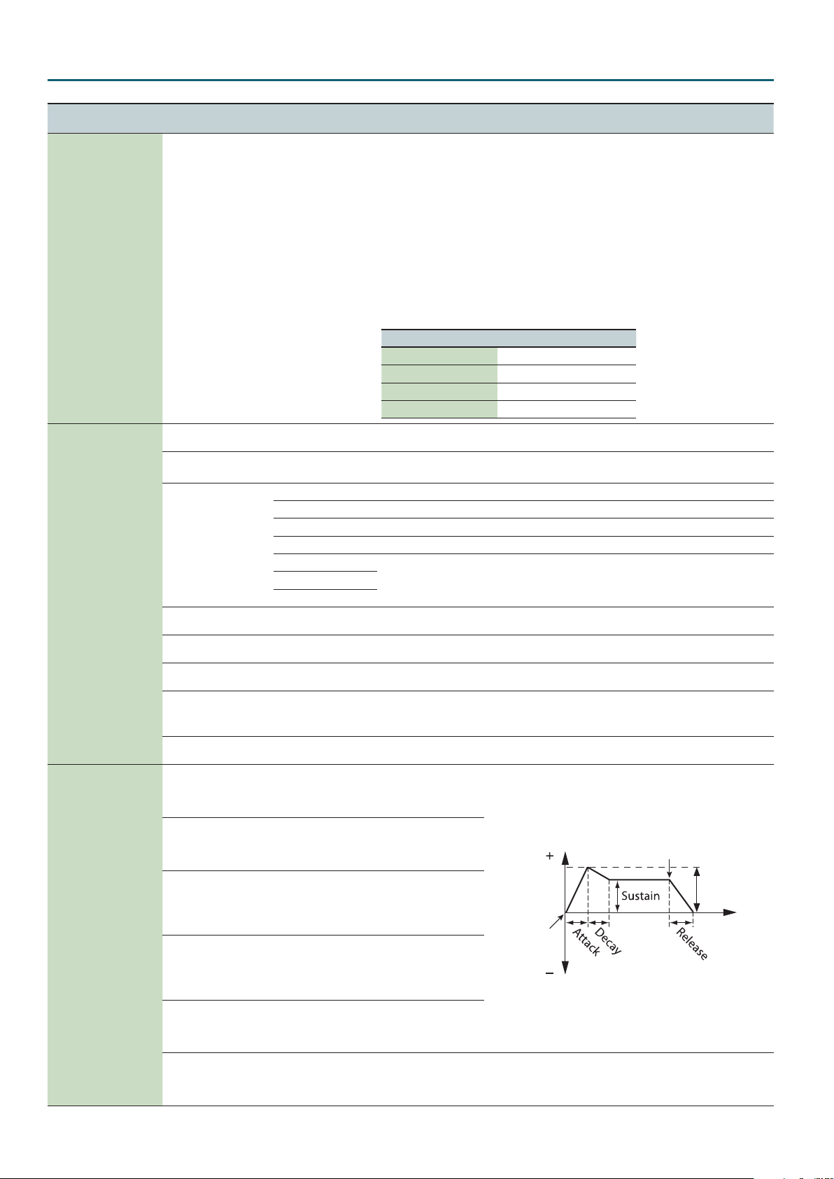
Species the depth and direction
of the pitch change.
Species the attack time of the
pitch envelope.
This species the time from the
moment you press the key until
the pitch reaches its highest
(or lowest) point.
Species the decay time of the
pitch envelope.
This species the time from the
moment the pitch reaches its
highest (or lowest) point until it
returns to the pitch of the key you
pressed.
Keyboard playing dynamics can
be used to control the depth of
the pitch envelope. If you want
the pitch envelope to have more
eect for strongly played notes,
set this parameter to a positive
(+) value. If you want the pitch
envelope to have less eect for
strongly played notes, set this to a
negative (-) value.
Selects the pitch envelope(s) that you want to edit.
OSC1+2: Edit the pitch envelopes of A-OSC1 and A-OSC2 simultaneously.
OSC1: Edit the pitch envelope of OSC1 individually.
OSC2: Edit the pitch envelope of OSC2 individually.
Species the AUX volume.
MEMO
If D-PART is selected as AUX Src, some sounds may be prone to clipping. If clipping occurs, adjust the AUX
Level.
Pitch
Key-on
Time
9
Page 10
Analog Part
Menu
[Shift] + Cursor [K] [J]
MIXER
(Mixer)
FILTER
(Filter)
FILTER ENV
(Filter Envelope)
Parameter
Cursor [K] [J]
AUX Src
(AUX Source)
HPF Cuto
(High Pass Filter Cuto)
Drive
(Filter Drive)
Type
(Filter Type)
Cuto
(Filter Cuto)
Cuto Fine
(Filter Cuto Fine)
Resonance
(Filter Resonance)
Key Follow
(Filter Key Follow)
KF Fine
(Filter Key Follow Fine)
Depth
(Filter Envelope Depth)
Attack
(Filter Envelope Attack Time)
Decay
(Filter Envelope Decay Time)
Sustain
(Filter Envelope Sustain Time)
Release
(Filter Envelope Release Time)
Velo Sens
(Filter Envelope Velocity Sensitivity)
Value
Value [-] [+]
Explanation
When you specify the AUX source and play the keyboard, the sound of the selected source is
heard.
About D-PART (Digital Part)
By selecting D-PART as the AUX Src, you can create sounds in which the sound of the digital part
is processed by the lter of the analog part. Here’s how the sound of digital part 01 can be input
to analog part 01.
1. Press the ANALOG PART ON [01] button so it’s lit.
2. Press the DIGITAL PART ON [01] button so it’s lit.
(White Noise)
WHITE
(Pink Noise)
PINK
(Digital Part)
D-PART
MIC
0–127 Species the cuto frequency of an high-pass lter.
0–127
Species the lter type.
BYPASS The lter is bypassed.
(Low Pass Filter 1)
LPF1
(Low Pass Filter 2)
LPF2
(Low Pass Filter 3)
LPF3
(High Pass Filter)
HPF
(Band Pass Filter)
BPF
0–127 Resonance emphasizes the sound in the region of the lter cuto frequency.
-50–0–+50 Resonance emphasizes the sound in the region of the lter cuto frequency.
0–127 Resonance emphasizes the sound in the region of the lter cuto frequency.
-10–0–+10
-50–0–+50 Applies a ne adjustment to Key Follow.
-63–0–+63
0–127
0–127
0–127
0–127
-63–0–+63
3. Press the ANALOG PART Select [01] button so it’s lit.
4. Set AUX Src to D-PART.
Now the sound of digital part 01 is input to analog part 01. Adjust AUX Level as necessary.
* The digital part (D-PART) that can be selected as the AUX source will be the same part
number as the analog part. It is not possible to select a dierent part.
Analog part Digital part selected
Analog part 01 Digital part 01
Analog part 02 Digital part 02
Analog part 03 Digital part 03
Analog part 04 Digital part 04
Species the drive.
Increasing this value produces a natural distortion.
A 4-pole lter of a circuit design often used by Roland, providing relatively standard operation.
A ladder lter using transistors, providing a strong character.
This is a multi-mode lter consisting of a simultaneous LPF, HPF, and BPF. Although it is a
relatively standard circuit, it is designed so that the resonance changes dramatically.
Here’s how you can make the lter cuto frequency to vary according to the key you play.
If the knob is turned toward the right, the cuto rises as you play higher notes.
If the knob is turned toward the left, the cuto falls as you play higher notes.
Species the direction
and depth to which the
cuto frequency will
change.
Species the time from
when the key is pressed
until the lter reaches its
Key-o
maximum depth.
Species the time from
when the lter reaches
its maximum depth
Cuto
Frequency
until it decreases to the
sustain level.
Key-on
Species the lter depth
that is maintained after
the attack and decay
times have elapsed until
the key is released.
Species the time from
when the key is released
until the lter reaches its
minimum depth.
Species how keyboard playing dynamics will aect the depth of the lter envelope. If you want
the lter envelope to have more eect for strongly played notes, set this parameter to a positive
(+) value. If you want the lter envelope to have less eect for strongly played notes, set this to
a negative (-) value.
Depth
Time
10
Page 11
Analog Part
Menu
[Shift] + Cursor [K] [J]
AMP
(Amp)
AMP ENV
(Amp Envelope)
Parameter
Cursor [K] [J]
Level
(Amp Level)
Level V-Sens
(Amp Level Velocity Sensitivity)
Attack
(Amp Envelope Attack Time)
Decay
(Amp Envelope Decay Time)
Sustain
(Amp Envelope Sustain Time)
Release
(Amp Envelope Release Time)
Value
Value [-] [+]
Explanation
0–127 This species the AMP Level.
Set this when you want the volume of the AMP to change depending on the force with which
you press the keys.
-63–0–+63
Set this to a positive (+) value to have the changes in AMP volume increase the more forcefully
the keys are played; to make the AMP play more softly as you play harder, set this to a negative
(-) value.
This species the time
from the moment you
0–127
press the key until the
maximum volume is
reached.
This species the
time from when the
0–127
maximum volume is
reached, until it decays
to the sustain level.
This species the
volume level that will be
0–127
maintained from when
the attack and decay
times have elapsed until
you release the key.
This species the time
from when you release
0–127
the key until the volume
reaches its minimum
value.
Level
Key-on
Key-o
Time
11
Page 12
Digital Part
Tone Edit
1. Press a DIGITAL PART Select [01]–[04] button to make it light.
You can select multiple parts by pressing multiple buttons simultaneously.
You can’t select analog parts and digital parts simultaneously.
Each digital part consists of three partials.
While editing, you can switch parts or change the selection to multiple parts.
& For details of the overall structure, refer to the “JD-XA Structure Diagram” inside the front cover of the Owner’s Manual.
2. Press the [Menu] button.
3. Use the cursor [
K
] [J] buttons to select “TONE EDIT” and press the [Enter] button.
TONE COMMON: Porta Sw parameter appears.
Menu
[Shift] + Cursor [K] [J]
Parameter
Cursor [K] [J]
Porta Sw
(Portamento Switch)
Porta Time
(Portamento Time)
PortaMode
(Portamento Mode)
Chroma Porta
Portamento)
Ring Switch OFF, ON
(Chromatic
Value
Value [-] [+]
OFF, ON Species whether the portamento eect will be applied (ON) or not (OFF).
0–127
NORMAL Portamento will always be applied.
LEGATO
OFF, ON If this is turned on, portamento will operate in semitone steps.
Explanation
When portamento is used, this species the time over which the pitch will change. Higher values
lengthen the time over which the pitch will change to the next note.
Portamento will be applied only when you play legato (i.e., when you press the next key before
releasing the previous key).
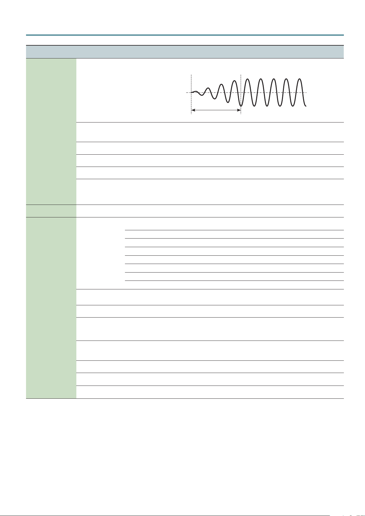
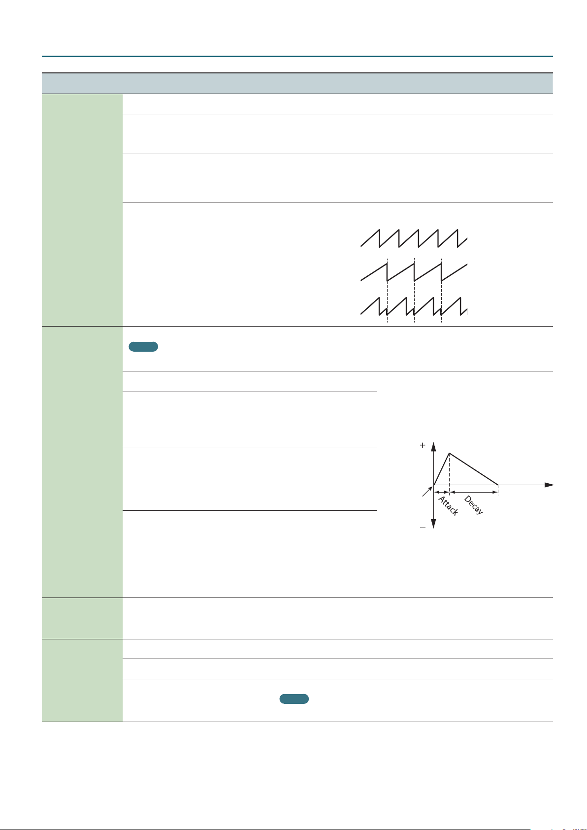
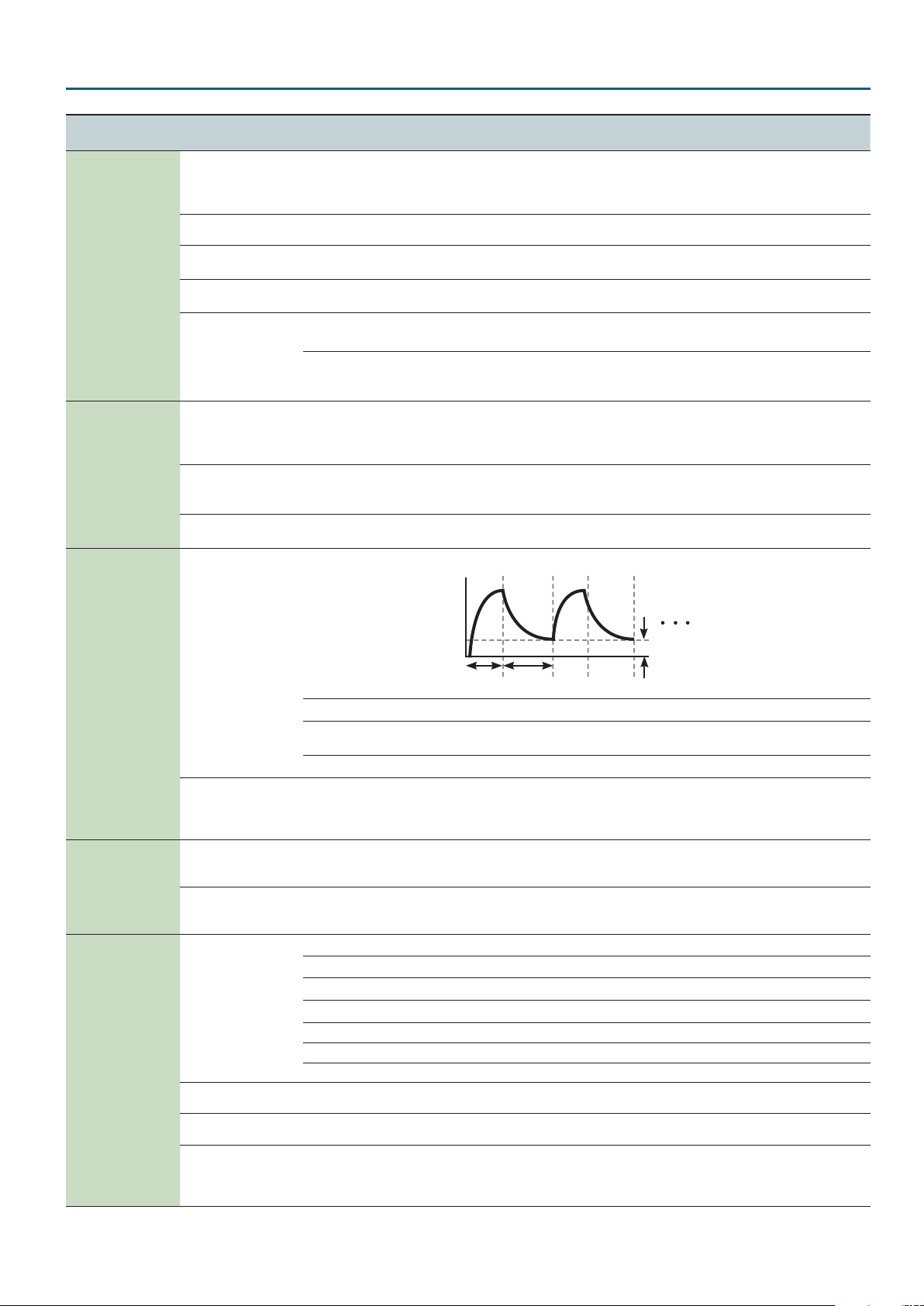
Turns ring modulator on/o.
By multiplying partial 1’s OSC and partial 2’s OSC, this creates a complex, metallic-sounding
waveform like that of a bell.
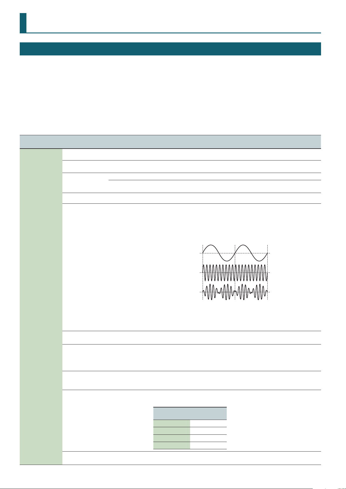
The partial 1’s OSC waveform will change as shown in the illustration, and partial 2’s OSC will be
output with its original waveform.
Setting the partial 1 OSC and the partial 2 OSC to dierent pitches will make the ring modulator
eect more apparent.
Partial 1’s OSC
waveform
Partial 2’s OSC
waveform
Partial 1’s OSC
output waveform
TONE COMMON
(Tone Common)
Mono/Poly
Legato Sw
(Legato Switch)
Unison Sw
(Unison Switch)
Unison Size 2, 4, 6, 8
Wave Shape 0–127
POLY
MONO
OFF, ON
OFF, ON
If Ring Switch is turned “ON,” the PWM Depth, PW, and S-Saw Detune of partial 1 and partial 2
cannot be used.
In addition, if an asymmetrical square wave is selected as the OSC waveform, the OSC variation
will be ignored, and there will be a slight dierence in sound compared to the originally selected
waveform.
Species whether notes will sound polyphonically (POLY) or monophonically (MONO).
This is valid only if the Mono/Poly parameter is set to “MONO.”
If this is “ON,” pressing a key while the previous key remains held down will cause the pitch to
change to that of the newly pressed key while maintaining the state in which the previous note
was being sounded. This creates a smooth transition between notes, which is eective when you
wish to simulate the hammering-on and pulling-o techniques used by a guitarist.
This layers a single sound.
If the Unison Switch is “ON,” the number of notes layered on one key will change according to the
number of keys you play.
Number of notes assigned to each key when the Unison Switch is “ON”
Example: If Unison Size is 8
Number of keys
pressed
1 8
2 4 each
3–4 2 each
5–8 1 each
Partial 1 will be modulated by the pitch of partial 2. Higher values produce a greater eect.
This has no eect if the partial 1 waveform is PW-SQR or SP-SAW.
Number of notes
sounded
12
Page 13
Digital Part
Menu
[Shift] + Cursor [K] [J]
TONE COMMON
(Tone Common)
INTERVAL SENS
(Interval Sens)
Parameter
Cursor [K] [J]
Analog Feel 0–127
Oct Shift
(Octave Shift)
Bend Range D
(Pitch Bend Range Down)
Bend Range U
(Pitch Bend Range Up)
Bend Mode
(Pitch Bend Mode)
Attack Time
(Attack Time Interval Sens)
Release Time
(Release Time Interval Sens)
Porta Time
Interval Sens)
(Portamento Time
Value
Value [-] [+]
Explanation
Species the depth of 1/f modulation that is to be applied to the tone (1/f modulation is a pleasant
and naturally-occurring ratio of modulation that occurs in a babbling brook or rustling wind.).
By adding this “1/f modulation,” you can simulate the natural instability characteristic of an
analog synthesizer.
-3–0–+3 Species the octave of the tone.
0–-24
0–+24
Species the amount of pitch change that occurs when the pitch bend/modulation lever is moved
all the way to the left.
Species the amount of pitch change that occurs when the pitch bend/modulation lever is moved
all the way to the right.
NORMAL The pitch bend lever works in the conventional way.
The pitch lever aects only the last-sounded note. If you play a note while the pitch bend lever is
C+L
(CATCH+LAST)
already moved, that note sounds at its normal pitch (as though the lever were in the center).
The pitch starts changing only after the lever passes through the center position.
Shortens the FILTER and AMP Attack Time according to the spacing between note-on events.
0–127
Higher values produce a greater eect. With a setting of 0, there will be no eect.
This is eective when you want to play rapid notes using a sound that has a slow attack
(Attack Time).
Shortens the FILTER and AMP Release Time if the interval between one note-on and the next note-
0–127
o is brief. Higher values produce a greater eect. With a setting of 0, there will be no eect.
This is eective when you want to play staccato notes using a sound that has a slow release.
0–127
Shortens the Portamento Time according to the spacing between note-on events. Higher values
produce a greater eect. With a setting of 0, there will be no eect.
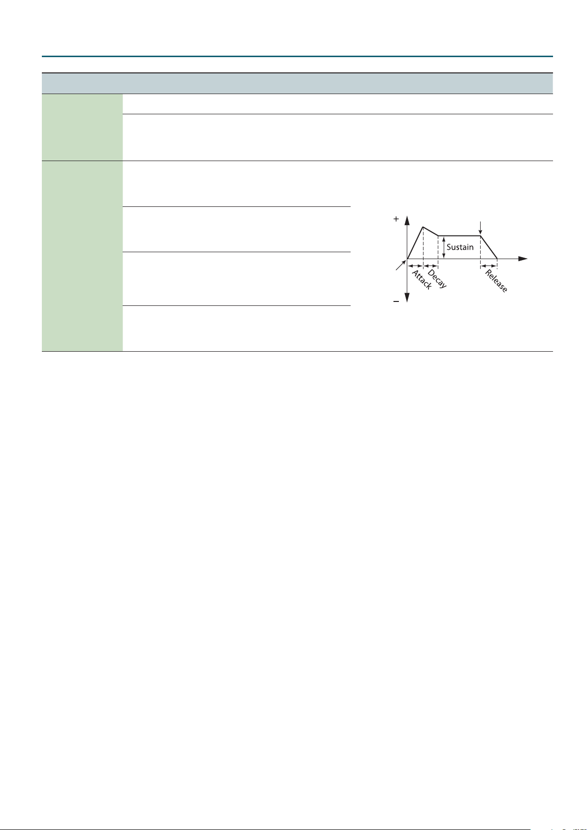
Use this to loop the envelope between certain regions during a note-on.
ENVELOPE LOOP
(Envelope Loop)
AFTERTOUCH
(Aftertouch)
LFO
(Low Frequency Oscillator)
Mode
(Envelope Loop Mode)
SyncNote
(Envelope Loop Sync Note)
Cuto Sens
(Cuto Aftertouch Sens)
Level Sens
(Level Aftertouch Sens)
Shape
(LFO Shape)
Tempo Sync
(LFO Tempo Sync Switch)
Rate
(LFO Rate)
Sync Note
(LFO Tempo Sync Note)
Sustain
Attack
Decay
OFF The envelope will operate normally.
FREE-RUN
When the Decay segment has ended, the envelope will return to the Attack. The Attack through
Decay segments will repeat until note-o occurs.
TEMPO-SYNC Species the loop rate as a note value (Sync Note parameter).
16, 12, 8, 4, 2, 1, 3/4,
2/3, 1/2, 3/8, 1/3, 1/4,
3/16, 1/6, 1/8, 3/32,
1/12, 1/16, 1/24, 1/32
Returns to the Attack at the specied rate. If the Attack+Decay time is shorter than the specied
rate, the Sustain Level will be maintained. If the Attack+Decay time is longer than the specied
rate, the envelope will return to the Attack even though the Decay has not been completed. This
will continue repeating until note-o occurs.
Species how aftertouch pressure will aect the cuto frequency. Specify a positive (+) value if you
-63–0–+63
want aftertouch to raise the cuto frequency; specify a negative (-) value if you want aftertouch to
lower the cuto frequency.
Species how aftertouch pressure will aect the volume. Specify a positive (+) value if you want
-63–0–+63
aftertouch to increase the volume; specify a negative (-) value if you want aftertouch to decrease
the volume.
Selects the LFO waveform.
TRI
SIN
SAW
SQR
S&H
S
: Triangle wave
R:
Sine wave
T:
Sawtooth wave
U:
Square wave
W:
Sample and Hold (The LFO value will change once each cycle.)
RND RND: Random wave
OFF, ON If this is ON, the LFO rate can be specied as a note value relative to the tempo.
0–127 Species the LFO rate when Modulation LFO Tempo Sync Switch is OFF.
16, 12, 8, 4, 2, 1, 3/4,
2/3, 1/2, 3/8, 1/3, 1/4,
3/16, 1/6, 1/8, 3/32,
Species the LFO rate when Modulation LFO Tempo Sync Switch is ON.
1/12, 1/16, 1/24, 1/32
13
Page 14
Digital Part
Menu
[Shift] + Cursor [K] [J]
LFO
(Low Frequency Oscillator)
MOD LFO
(Modulation LFO)
Parameter
Cursor [K] [J]
Key Trigger
(LFO Key Trigger)
Fade Time
(LFO Fade Time)
Pitch Depth
(LFO Pitch Depth)
Filter Depth
(LFO FILTER Depth)
Amp Depth
(LFO AMP Depth)
Pan Depth
(LFO Pan Depth)
Shape
(Modulation LFO Shape)
Tempo Sync
(Modulation LFO Tempo Sync
Switch)
Rate
(Modulation LFO Rate)
Sync Note
(Modulation LFO Tempo Sync Note)
Pitch Depth
(Modulation LFO Pitch Depth)
Filter Depth
(Modulation LFO FILTER Depth)
Amp Depth
(Modulation LFO AMP Depth)
Pan Depth
(Modulation LFO Pan Depth)
Rate Control
(Modulation LFO Rate Control)
Value
Value [-] [+]
Explanation
OFF, ON If this is ON, the LFO cycle will be restarted when you press a key.
Species the time from when the partial sounds until the LFO reaches its maximum amplitude.
0–127
Fade Time
-63–0–+63 This allows the LFO to modulate the pitch of the partial, producing a vibrato eect.
-63–0–+63 This allows the LFO to modulate the FILTER CUTOFF (cuto frequency), producing a wah eect.
-63–0–+63 This allows the LFO to modulate the AMP LEVEL (volume), producing a tremolo eect.
-63–0–+63 This allows the LFO to make the PAN (stereo position) vary (auto panning).
In addition to the LFO that is always applied to the partial, there is a Modulation LFO (MOD LFO) that is controlled by the
modulation controller (CC01).
Selects the Modulation LFO waveform.
TRI
SIN
SAW
SQR
S&H
S:
Triangle wave
R:
Sine wave
T:
Sawtooth wave
U:
Square wave
W:
Sample and Hold (The LFO value will change once each cycle.)
RND RND: Random wave
OFF, ON If this is ON, the LFO rate can be specied as a note value relative to the tempo.
0–127 Species the LFO rate when MOD LFO Tempo Sync Switch is OFF.
16, 12, 8, 4, 2, 1, 3/4,
2/3, 1/2, 3/8, 1/3, 1/4,
3/16, 1/6, 1/8, 3/32,
Species the LFO rate when MOD LFO Tempo Sync Switch is ON.
1/12, 1/16, 1/24, 1/32
-63–0–+63 Species how the modulation controller (CC01) will vary the pitch of the tone (vibrato).
-63–0–+63
-63–0–+63
-63–0–+63
Species how the modulation controller (CC01) will vary the depth of LFO lter cuto modulation
(wah).
Species how the modulation controller (CC01) will vary the depth of LFO amp level (volume)
modulation (tremolo).
Species how the modulation controller (CC01) will vary the depth of LFO pan (stereo position)
modulation (auto panning).
Species how the modulation controller (CC01) will vary the MOD LFO Rate.
Specify a positive (+) value if you want the Modulation LFO rate to become faster when you raise
-63–0–+63
the modulation controller (CC01) value; specify a negative (-) value if you want the rate to become
slower.
* This is valid if Tempo Sync is OFF.
14
Page 15
Digital Part
Menu
[Shift] + Cursor [K] [J]
OSC
(Oscillator)
PITCH ENV
(Pitch Envelope)
Parameter
Cursor [K] [J]
Value
Value [-] [+]
Explanation
(Waveform) Refer to “Digital OSC Waveform List” (p. 74).
Pitch
(OSC Pitch)
Detune
(OSC Detune)
-24–0–+24 Adjusts the pitch in semitone steps.
-50–0–+50 Adjusts the pitch in steps of one cent.
Species the amount (depth) of LFO applied to PW (Pulse Width).
PWM Depth
Modulation Depth)
(Pulse Width
0–127
If the Waveform has selected V (PW-SQR), you can use this slider to specify the amount of LFO
modulation applied to PW (pulse width).
* If the Ring Switch is on, this has no eect on partials 1 and 2.
Species the pulse width.
If the OSC Wave has selected V (PW-SQR), you can use this slider to specify the width of the upper
PW
(Pulse Width)
0–127
portion of the square wave (the pulse width).
Decreasing the value will decrease the width, approaching a square wave (pulse width = 50%).
Increasing the value will increase the width, producing a distinctive sound.
* If the Ring Switch is ON, this has no eect on partials 1 and 2.
Sets the gain (amplication) of the waveform.
PCM Gain -6, 0, +6, +12
The value changes in 6 dB (decibel) steps—an increase of 6 dB doubles the waveform’s gain.
* This is eective if Waveform is set to 001:JP-8 Saw or a subsequent waveform.
Species the amount of pitch dierence between the seven sawtooth waves layered within a
single oscillator.
S-Saw Detune
(Super Saw Detune)
0–127
Higher values will increase the pitch dierence. (OSC Detune applies an equal amount of pitch
dierence between each of the seven sawtooth waves.)
* If the Ring Switch is ON, this has no eect on partials 1 and 2.
* This is valid only if SUPER-SAW is selected for the Waveform.
PW Shift 0–127
Depth
(Pitch Envelope Depth)
Attack
(Pitch Envelope Attack Time)
Decay
(Pitch Envelope Decay Time)
-63–0–+63 Species the direction and depth to which the pitch will change.
0–127
0–127
Shifts the range of PW (pulse width) change. Normally, you can leave this at 127.
* If the Ring Switch is ON, this has no eect on partials 1 and 2.
Species the attack time of the pitch envelope.
This species the time from the moment you press the key until the pitch reaches its highest
(or lowest) point.
Species the decay time of the pitch envelope.
This species the time from the moment the pitch reaches its highest (or lowest) point until it
returns to the pitch of the key you pressed.
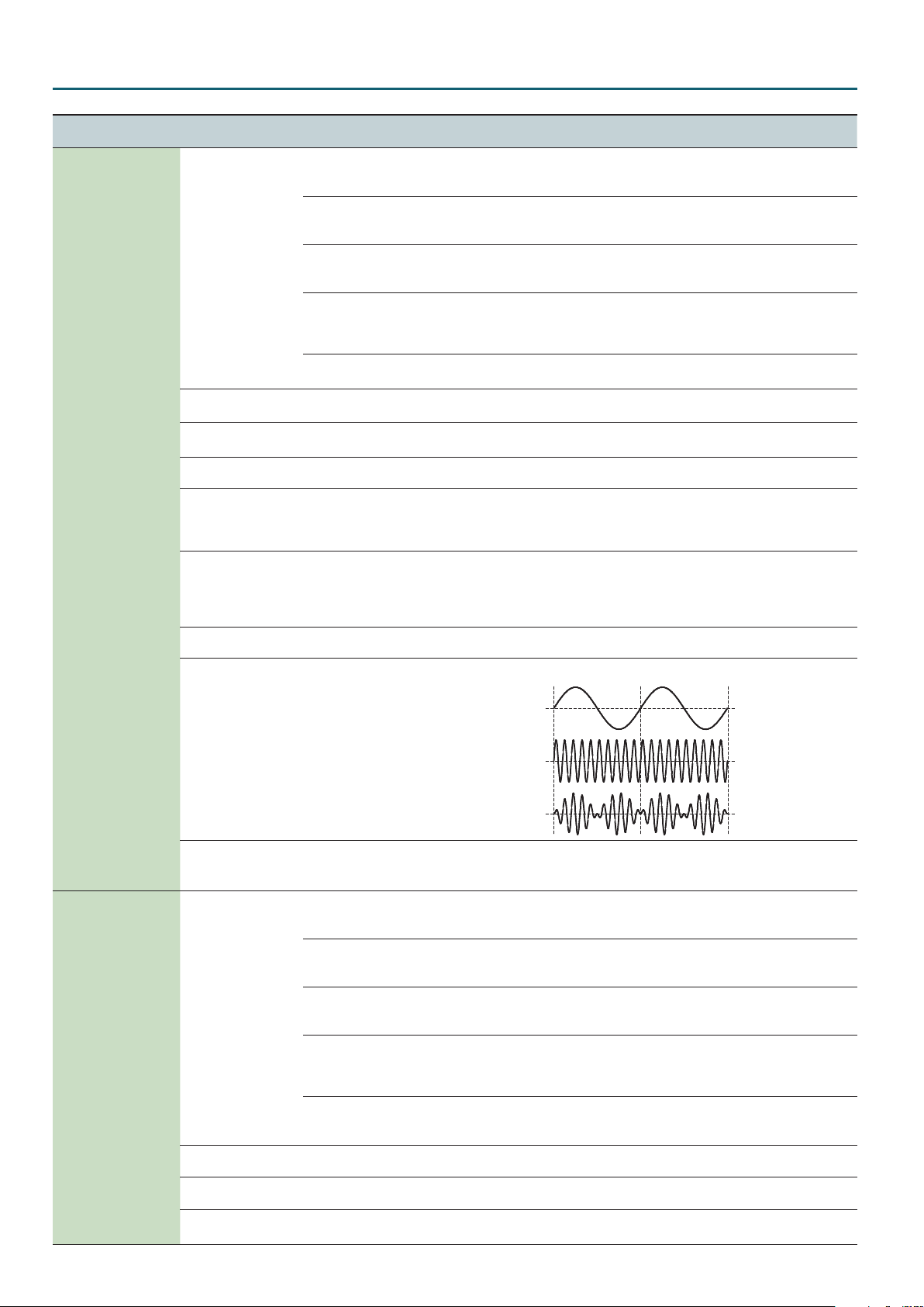
Species the cuto frequency of an independent -6 dB high-pass lter.
FILTER
(Filter)
HPF Cuto 0–127
BYPASS
LPF1 (-24 dB)
LPF2 (-24 dB)
LPF3 (-24 dB)
HPF (-24 dB)
BPF (-24 dB)
Type
(Filter Type)
LPF4 (-24 dB)
PKG (-24 dB)
LPF1 (-12 dB)
LPF2 (-12 dB)
LPF3 (-12 dB)
LPF4 (-12 dB)
HPF (-12 dB)
BPF (-12 dB)
PKG (12 dB)
Cuto
(Filter Cuto)
Resonance
(Filter Resonance)
0–127 Species the cuto frequency.
0–127 Resonance emphasizes the sound in the region of the lter cuto frequency.
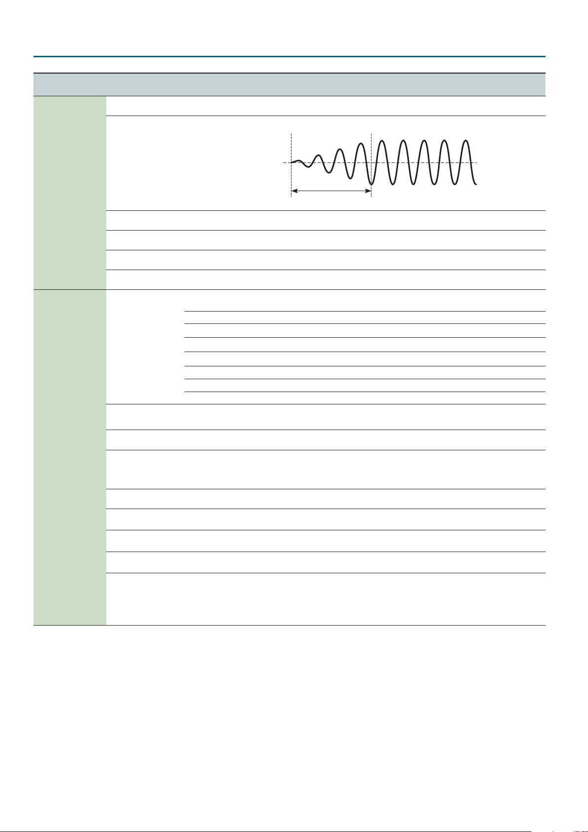
-6 dB HPF
Selects the type and slope of the lter.
For the LPF
Level
frequency
BYPASS, LPF, HPF,
BPF, PKG
-24 dB
-12 dB
FrequencyCuto
15
Page 16
Digital Part
Menu
[Shift] + Cursor [K] [J]
FILTER
(Filter)
FILTER ENV
(Filter Envelope)
AMP
(AMP)
AMP ENV
(AMP Envelope)
Parameter
Cursor [K] [J]
Key Follow
(Filter Cuto Key Follow)
Depth
(Filter Envelope Depth)
Attack
(Filter Envelope Attack)
Decay
(Filter Envelope Decay)
Sustain
(Filter Envelope Sustain)
Release
(Filter Envelope Release)
Velo Sens
(Filter Envelope Velocity Sensitivity)
Level
(AMP Level)
Pan
(AMP Pan)
Level V-Sens
(AMP Level Velocity Sensitivity)
Key Follow
(AMP Level Keyfollow)
Attack
(AMP Envelope Attack)
Decay
(AMP Envelope Decay)
Sustain
(AMP Envelope Sustain)
Release
(AMP Envelope Release)
Value
Value [-] [+]
Explanation
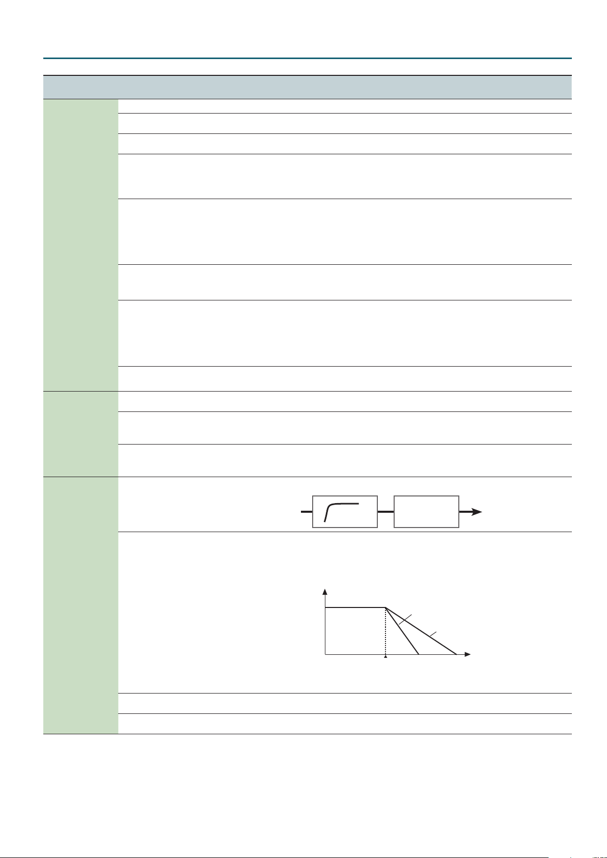
Here’s how you can make the lter cuto frequency to vary according to the key you play.
Cuto frequency
(Octave)
+2
+1
-10–0–+10
0
-1
-2
Species the direction and depth
-63–0–+63
to which the cuto frequency will
change.
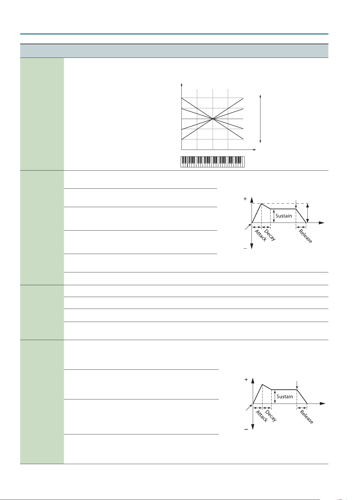
Species the time from when
0–127
the key is pressed until the lter
reaches its maximum depth.
Species the time from when the
0–127
lter reaches its maximum depth
until it decreases to the sustain
level.
Species the lter depth that is
0–127
maintained after the attack and
decay times have elapsed until
the key is released.
Species the time from when
0–127
the key is released until the lter
reaches its minimum depth.
-63–0–+63
Here’s how you can make the lter envelope depth vary according to the strength with which you
play the key.
0–127 Partial volume.
L64–0–63R The stereo position of the partial.
-63–0–+63
Here’s how you can make the volume vary according to the strength with which you play the
keyboard.
Specify this if you want to vary the volume according to the position of the key that you play. With
-10–0–+10
the C4 key (middle C) as the base volume, “+” values will make the volume increase as you play
above C4; “-” values will make the volume decrease. Higher values will produce greater change.
Species the attack time of the
amp envelope.
0–127
This species the time from the
moment you press the key until
the maximum volume is reached.
Species the decay time of the
amp envelope.
0–127
This species the time from when
the maximum volume is reached,
until it decays to the sustain level.
Species the sustain level of the
amp envelope.
0–127
This species the volume level
that will be maintained from when
the attack and decay times have
elapsed until you release the key.
Species the release time of the
amp envelope.
0–127
This species the time from when
you release the key until the
volume reaches its minimum value.
C4C3C2 C5 C6
Cuto
frequency
Key-on
Level
Key-on
+10
+5
0
-5
-10
High
Value
Low
Key
Key-o
Depth
Time
Key-o
Time
16
Page 17
Eects
To move MFX, PART EQ, TFX1, TFX2, REVERB, or DELAY, hold down the [Shift] button and use the cursor [K][J] buttons.
Eects Edit
1. Press the [Menu] button.
2. Use the cursor [
K
MFX: Switch parameter appears.
Eect type
[Shift] + Cursor [K] [J]
MFX PART (TONE)
PART EQ PAR T
TFX1/TFX2 PROGRAM
REVERB PROGRAM
DELAY PROGRAM
MFX Edit
Menu
[Shift] + Cursor [K] [J]
MFX
(MFX)
MFX CTRL
(MFX Control)
Parameter
Cursor [K] [J]
Switch
(MFX Switch)
Use this parameter to select from among the 67 available MFXs. For details on multi-eects parameters, refer to “MFX Parameters” (p. 25).
Src1
(Source 1)
Src2
(Source 2)
Src3
(Source 3)
Src4
(Source 4)
Dest1
(Destination 1)
Dest2
(Destination 2)
Dest3
(Destination 3)
Dest4
(Destination 4)
Sens1, Sens2, Sens3,
Sens4
] [J] buttons to select “EFFECTS EDIT” and press the [Enter] button.
Parameter storage location
Value
Value [-] [+]
OFF, ON Species whether multi-eect will be used (ON) or not used (OFF).
Sets the MIDI message used to change the multi-eects parameter with the MFX Control.
OFF Multi-eects control will not be used.
CC01–CC31
CC33–CC95
BEND Pitch bend
AFT Aftertouch
SYS1, SYS2, SYS3, SYS4 MIDI messages used as common multi-eects controls.
Refer to the parameters marked “#” on “MFX Parameters” (p. 25) and following.
-63–0–+63
Explanation
Controller number 1–31, 33–95
Species the depth of MFX Control. To make an increase in the currently selected value (to get
higher values, move to the right, increase rates, and so on), select a positive value; to make a
decrease in the currently selected value (to get lower values, move to the left, decrease rates,
and so on), select a negative value. For either positive or negative settings, greater absolute
values will allow greater amounts of change. Set this to “0” if you don’t want to apply the eect.
17
Page 18
Eects
Part EQ Edit
Menu
[Shift] +Cursor [K] [J]
PART EQ
(Part Equalizer)
Parameter
Cursor [K] [J]
Switch
(Part Equalizer Switch)
Low Freq
(Part Equalizer Low Frequency)
Low Gain
(Part Equalizer Low Gain)
Mid Freq
(Part Equalizer Mid Frequency)
Mid Gain
(Part Equalizer Mid Gain)
Q
(Part Equalizer Mid Q)
High Freq
(Part Equalizer High Frequency)
High Gain
(Part Equalizer High Gain)
Value
Value [-] [+]
Explanation
OFF, ON EQ for each part on/o setting
16 Hz, 20 Hz, 25 Hz, 31
Hz, 40 Hz, 50 Hz, 63 Hz,
80 Hz, 100 Hz, 125 Hz,
160 Hz, 200 Hz, 250 Hz,
Frequency of the low range.
315 Hz, 400 Hz, 500 Hz,
630 Hz, 800 Hz
-15 dB–0–+15 dB Gain of the low frequency range
16 Hz, 20 Hz, 25 Hz, 31
Hz, 40 Hz, 50 Hz, 63 Hz,
80 Hz, 100 Hz, 125 Hz,
160 Hz, 200 Hz, 250
Hz, 315 Hz, 400 Hz, 500
Hz, 630 Hz, 800 Hz,
1000 Hz, 1250 Hz, 1600
Frequency of the middle range
Hz, 2000 Hz, 2500 Hz,
3150 Hz, 4000 Hz, 5000
Hz, 6300 Hz, 8000 Hz,
10000 Hz, 12500 Hz,
16000 Hz
-15 dB–0–+15 dB Gain of the middle frequency range
0.5, 1.0, 2.0, 4.0, 8.0
630 Hz,
, 800 Hz, 1000
Width of the middle frequency range
Set a higher value for Q to narrow the range to be aected.
Hz, 1250 Hz, 1600 Hz,
2000 Hz, 2500 Hz, 3150
Hz, 4000 Hz, 5000 Hz,
Frequency of the high range
6300 Hz, 8000 Hz, 10000
Hz, 12500 Hz, 16000 Hz
-15 dB–0–+15 dB Gain of the high frequency range
TFX Edit
Menu
[Shift] +Cursor [K] [J]
TFX1
(TFX 1)
TFX2
(TFX 2)
Parameter
Cursor [K] [J]
Type
(TFX Type)
Ctrl
(TFX Control)
Switch
(TFX Switch)
Parameters for each type
& “TFX Parameters” (p. 19)
Limit ModeSw
(TFX Limit Mode Switch)
HeadMargin
(TFX Head Margin)
Value
Value [-] [+]
00–29
0–127
OFF, ON
OFF, ON
-18 dB, -15 dB, -12 dB,
-9 dB, -6 dB, -3 dB, 0 dB
Explanation
Use this parameter to select from among the 29 available total eect. For details on total eect
parameters, refer to “TFX Parameters” (p. 19).
Globally controls the selected total eect.
Global control means to control multiple parameters simultaneously.
Species whether total eect will be used (ON) or not used (OFF).
Edit the parameters for the selected TFX type.
If you turn Limit Mode on, the eect depth is restricted to prevent feedback or an extremely
high volume.
Parameters that are aected by Limit Mode are indicated by a
symbol (p. 19). This can be
convenient when you’re performing in high-volume conditions at a club or hall.
* This parameter is not shown for types that have no parameters marked by
.
Simultaneously adjusts the input and output gain of the total eect.
This is convenient when adjusting dynamics-type eects (such as overdrive or compressor) that
produce their eect by varying the volume. For some eects, it may be dicult to notice the
result of this adjustment.
18
Page 19
TFX Parameters
Parameters that are aected by Limit Mode are indicated by a symbol.
Parameter Value Explanation
Eects
01: Flt+Drive
A low-pass lter with overdrive. It cuts the high frequencies and adds distortion.
Cuto 0–127 Adjusts the frequency that will be cut.
Resonance
Drive
02: Isolator
Isolates or removes the low, mid, or high frequency ranges.
Low
Mid
High
03: DJFX Looper
Loops a short portion of the input sound. You can vary the playback direction and playback speed of the input sound to add turntable-type eects.
Length
Speed -1.0–+1.0
Loop Sw OFF, ON If you turn this on while sound is playing, the sound at that point will be looped. Turn this o to cancel the loop.
04: BPM Looper
Loops a short portion of the input sound.
Length
Timing OFF, 1–8
Loop Sw OFF, ON If you turn this on while sound is playing, the sound at that point will be looped. Turn this o to defeat looping.
(FILTER+DRIVE)
0–127 Adjusts peak frequency response at the cuto frequency.
0–127 Adds distortion.
(ISOLATOR)
0–127 Isolates/removes the low-frequency range.
0–127 Isolates/removes the mid-frequency range.
0–127 Isolates/removes the high-frequency range.
(DJFX LOOPER)
0–127 Species the length of the loop.
Species the playback direction and playback speed.
Negative (-) settings make the sound play backward. Positive (+) settings make the sound play forward. With a value of
0.0, playback stops.
(BPM LOOPER)
0–127 Species the length of the loop.
Species the timing (in 8th note units) at which sounds looped during a measure will automatically start playing. If you
don’t want the loop to play automatically, turn this “OFF.”
05: Bit Crush
This creates a lo- sound.
Sample Rate 0–127 Adjusts the sample rate.
Bit
Filter 0–127 Adjusts the lter depth.
06: Wah
Peak 0–127 Adjusts the width of frequencies to which eect is applied.
Rate 0–127 Adjust the speed of modulation.
Manual 0–127 Adjusts the pitch of the eect sound.
(WAH)
Produces a wah eect.
07: Reverb
Adds reverberation to the sound.
Reverb Time 0–127 Adjusts the reverberation time.
Tone 0–127 Adjusts the tone of the reverberation.
Balance D64–63E Adjusts the volume balance between the direct sound and eect sound.
08: Delay
Repeats the sound.
Delay Time Note *1 Adjusts the interval of the repeats.
Feedback
Balance D64–63E Adjusts the volume balance between the direct sound and eect sound.
(DELAY)
09: Tape Echo
Simulates a tape-type echo unit of the past.
Rate 0–127 Species the tape speed.
Intensity 0–127 Species the amount of echo repeat.
Balance D64–63E Adjusts the volume balance between the direct sound and eect sound.
(BIT CRUSH)
0–127 Adjusts the bit depth.
(REVERB)
0–127 Adjusts the number of the repeats.
(TAPE ECHO)
19
Page 20
Eects
Parameter Value Explanation
10: Pitch Sft
Changes the pitch.
Pitch 0–127 Adjusts the amount of pitch change.
Feedback
Balance D64–63E Adjusts the volume balance between the direct sound and eect sound.
11: Voice Trans
Processes a human voice to create a variety of characters.
Formant 0–127 Adjusts the character (formant) of the voice.
Eect Level 0–127 Adjusts the volume of the eect sound.
Direct Level 0–127 Adjusts the volume of the direct sound.
12: Flanger
Creates modulation reminiscent of a jet airplane taking o and landing.
Depth 0–127 Adjusts the depth of modulation.
Rate 0–127 Adjusts the speed of modulation.
Feedback
Balance D64–63E Adjusts the volume balance between the direct sound and eect sound.
13: Slicer+Flg
Repeatedly cuts the sound. A anger is added.
Timing Ptn
(Timing Pattern)
Rate Note *1 Adjusts the length of Timing Pattern.
Feedback
Attack 0–127 Adjusts the speed at which the level will change between steps.
(PITCH SHIFTER)
0–127 Adjusts the amount of pitch-shifted sound that is fed back.
(VOICE TRANS)
(FLANGER)
0–127 Adjusts the proportion of eect sound that is returned to the input.
(SLICER+FLANGER)
P01–P16 *2 The timing at which the sound is cut.
0–127 Adjusts the anger depth.
14: Phaser
Creates modulation by adding a phase-shifted sound.
Depth
Rate 0–127 Adjusts the speed of modulation.
Manual 0–127 Adjusts the pitch of the eect sound.
Balance D64–63E Adjusts the volume balance between the direct sound and eect sound.
15: Chorus
Adds spaciousness and richness to the sound.
Depth 0–127 Adjusts the depth of modulation.
Rate 0–127 Adjusts the rate of modulation.
Balance D64–63E Adjusts the volume balance between the direct sound and eect sound.
16: Tremolo/Pan
Cyclically varies the volume or panning.
Depth 0–127 Adjusts the amount of change in volume/panning.
Rate 0–127 Adjusts the speed of volume/panning change.
Waveform TRM, PAN Switches the curve of the cyclic change in volume (TRM) / panning (PAN).
17: Overdrive
Mildly distorts the sound.
Drive
Tone
Level
(PHASER)
0–127 Adjusts the depth of modulation.
(CHORUS)
(TREMOLO/PAN)
(OVERDRIVE)
0–127 Adjusts the degree of distortion.
0–127 Adjusts the tone.
0–127 Adjusts the volume.
18: Distortion
Intensely distorts the sound.
Drive
Tone
Level
0–127 Adjusts the degree of distortion.
0–127 Adjusts the tone.
0–127 Adjusts the volume.
(DISTORTION)
20
Page 21
Parameter Value Explanation
Eects
19: Fuzz
Adds overtones and intensely distorts the sound.
Drive
Tone
Level
20: Octave
Adds a pitch at lower octaves.
-2 Oct Level 0–127 Adds a pitch two octaves below.
-1 Oct Level 0–127 Adds a pitch one octave below.
Direct Level 0–127 Adjusts the volume of the direct sound.
21: Subsonic
Adds a low-frequency sine wave based on the volume being input to the eect (*3).
Pitch 0–127 Adjusts the frequency of the sine wave.
Threshold 0–127 Adjusts the volume at which the sine wave will begin sounding.
Balance D64–63E Adjusts the volume balance between the direct sound and eect sound.
22: Ring Mod
Gives the sound a metallic character.
Frequency
Sens
Balance D64–63E Adjusts the volume balance between the direct sound and eect sound.
23: ChromaticPS
A two-voice pitch shifter that changes the pitch in semitone steps.
Pitch1 -12–+12 Changes pitch 1 in semitone steps over a +/-1 octave range.
Pitch2 -12–+12 Changes pitch 2 in semitone steps over a +/-1 octave range.
Balance D64–63E Adjusts the volume balance between the direct sound and eect sound.
(FUZZ)
0–127 Adjusts the degree of distortion.
0–127 Adjusts the tone.
0–127 Adjusts the volume.
(OCTAVE)
(SUBSONIC)
(RING MODULATOR)
0–127 Adjusts the pitch of the metallic sound.
0–127 Adjusts the depth to which the frequency is modulated.
(CHROMATIC PITCH SHIFTER)
24: C.Canceller
Cancels the vocal or other sound located in the center.
L-R Balance L64–63R Adjusts the point at which maximum cancellation occurs.
Low Boost 0–127 Boosts the low-frequency sounds located in the center, such as the bass.
High Boost 0–127 Boosts the high-frequency sounds.
25: Vinyl Sim
Simulates sound heard from an analog record.
Freq Range
(Frequency Range)
Noise Level 0–127 Adjusts the volume of noise.
Wow/Flutter 0–127 Adjusts the rotational instability of the analog record.
0–127 Adjusts the frequency response of the playback system.
26: RadioTuning
Simulates sound heard from a radio.
Detune 0–127 Adjusts the tuning drift of the radio.
Noise Level 0–127 Adjusts the volume of noise.
Balance D64–63E Adjusts the volume balance between the direct sound and eect sound.
27: Noise Gen
Applies a lo- eect, and also adds noises such as white noise and record noise.
White Noise 0–127 Adjusts the volume of the “hiss” noise.
Disc Noise 0–127 Adjusts the volume of the “pop” noise.
Hum Noise 0–127 Adjusts the volume of the “hum” noise.
(CENTER CANCELLER)
(VINYL SIMULATOR)
(RADIO TUNING)
(NOISE GENERATOR)
21
Page 22
Eects
Parameter Value Explanation
28: Comp
(COMPRESSOR)
Makes the sound more consistent.
Sustain 0–127 Adjusts the depth of the compressor.
Attack
Level
29: Equalizer
0–127 Adjusts the attack. If Limit mode is on, this adjusts the release.
0–127 Adjusts the volume.
(EQUALIZER)
Adjusts the volume of each frequency region.
Low
Mid
High
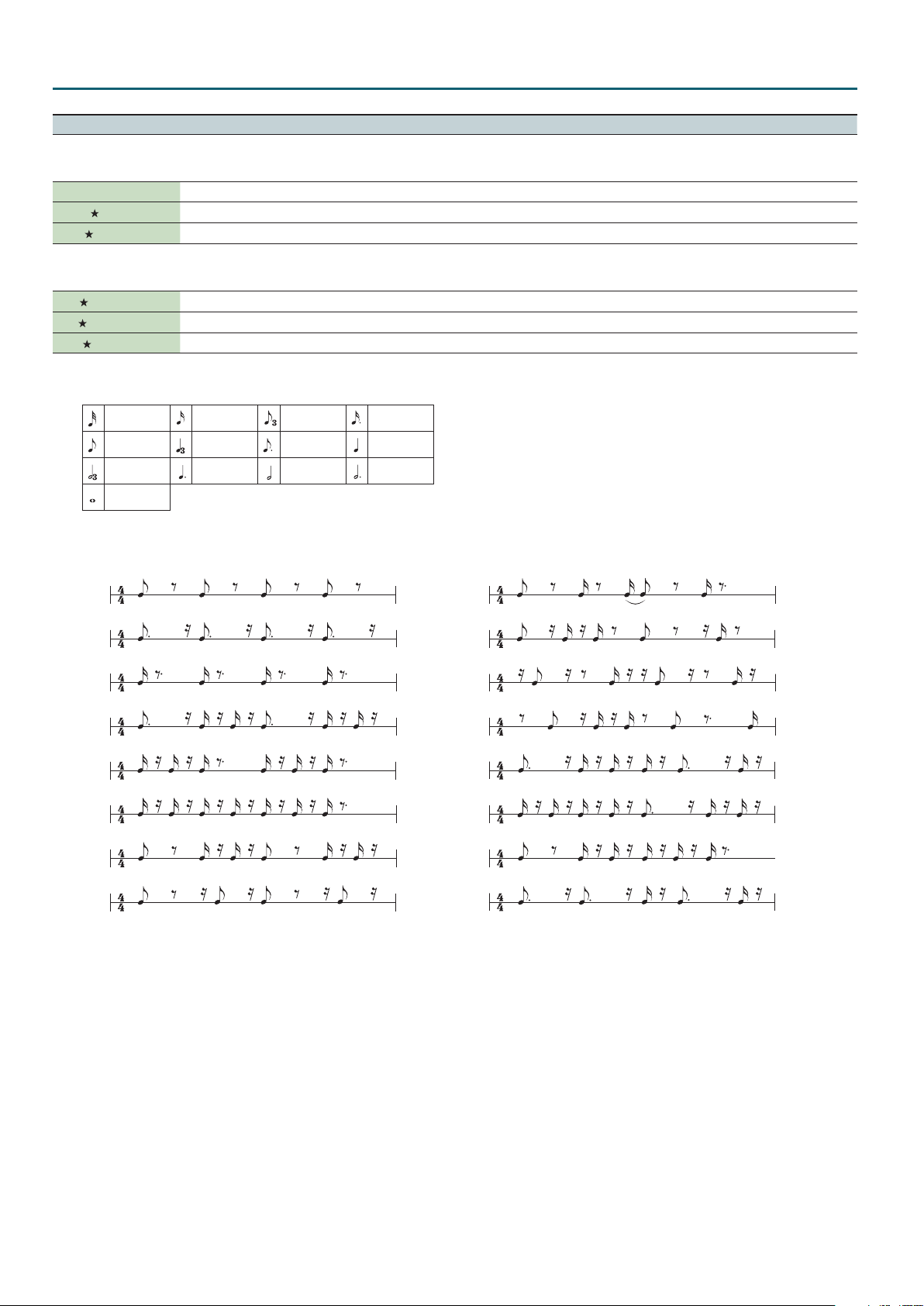
*1: This setting is specied as a note value relative to the sequencer’s tempo.
Note values that you can specify:
Thirty-second note Sixteenth note Eighth-note triplet
Eighth note Quarter-note triplet Dotted eighth note Quarter note
Half-note triplet Dotted quarter note Half note Dotted half note
Whole note
However, you can’t select a setting that would cause the delay time to exceed approximately 2,000 msec.
*2: Choose from the following Timing Patterns.
P01
0–127 Adjusts the low-frequency volume.
0–127 Adjusts the mid-frequency volume.
0–127 Adjusts the high-frequency volume.
Dotted sixteenth
note
P09
P02
P03
P04
P05
P06
P07
P08
The cycle of the Timing Pattern is based on a 4/4 time signature.
You can use Rate to adjust the synchronization speed as follows.
Rate maximum: One cycle of Timing Pattern corresponds to one measure.
Rate minimum: One cycle of Timing Pattern corresponds to a 32nd note.
By changing the Rate setting you can change the cycle in the range between a 32nd note to one full measure.
*3: Set Balance to the center value, adjust PITCH to raise the frequency of the sine wave, and set Threshold so that the sine wave is heard appropriately for the input source.
After you’ve nished setting the Threshold, adjust the Pitch and Balance. This is a useful way to strengthen a kick drum.
P10
P11
P12
P13
P14
P15
P16
22
Page 23
REVERB Edit
Eects
Menu
[Shift] +Cursor [K] [J]
REVERB
(Reverb)
Parameter
Cursor [K] [J]
Level
(Reverb Level)
Switch
(Reverb Switch)
Value
Value [-] [+]
0–127
OFF, ON
Explanation
Adjusts the volume of reverb sound.
Switches the reverb on/o.
Reverb Parameters
Parameter Value Explanation
00: OFF
01: Room 1
02: Room 2
Reverb Type
03: Hall 1
04: Hall 2
05: Plate
06: GM2 Reverb
01–05: Room 1/2, Hall 1/2, Plate
Pre Delay 0–100 ms (msec) Adjusts the delay time from the direct sound until the reverb sound is heard.
Time 0.1–10 s (sec) Time length of reverberation
Density 0–127 Density of reverb
Diusion 0–127
LF Damp 0–100 Adjusts the low-frequency portion of the reverb.
HF Damp 0–100 Adjusts the high-frequency portion of the reverb.
Spread 0–127 Reverb spread
Tone 0–127 Tonal character of the reverb
Selects the type of reverb.
OFF: Reverb will not be used
Room 1/2: Reverb that simulates the reverberation of a room
Hall 1/2: Reverb that simulates the reverberation of a hall
Plate: Simulation of a plate echo
GM2 Reverb: GM2 reverb
Adjusts the change in the density of the reverb over time.
The higher the value, the more the density increases with time.
(The eect of this setting is most pronounced with long reverb times.)
06: GM2 Reverb
Character 0–5 Type of reverb
Time 0–127 Time length of reverberation
PROGRAM EFX Edit
Menu
[Shift] +Cursor [K] [J]
PROGRAM EFX
(Program EFX)
The applicable MFX types are listed below.
04: Step Flt
06: Auto Wah
07: Humanizer
09: Phaser1
12: Step Ph
(Step Filter)
(Auto Wah)
(Humanizer)
(Phaser 1)
(Step Phaser)
13: Mlt Phaser
16: Tremolo
17: Auto Pan
18: Slicer
22: Chorus
23: Flanger
24: Step Flg
25: Hexa-Cho
26: Tre Cho
27: Space-D
34: Delay
35: Mod Delay
(Tremolo)
(Auto Pan)
(Slicer)
(Chorus)
(Flanger)
(Step Flanger)
(Hexa-Chorus)
(Tremolo Chorus)
(Space-D)
(Delay)
(Modulation Delay)
36: 3Tap Delay
Parameter
Cursor [K] [J]
FX TempoSync
(EFX Tempo Sync Switch)
(Multi Stage Phaser)
(3 Tap Pan Delay)
Value
Value [-] [+]
OFF, ON
37: 4Tap Delay
38: Mlt Tap Dly
39: Rvs Delay
40: Tm Ctrl Dly
43: Pitch Sft
44: 2Voice PS
45: Od->Cho
46: Od->Flg
47: Od->Dly
48: Dist->Cho
49: Dist->Flg
50: Dist->Dly
52: OD/DS->AWah
57: EP->Tre
58: EP->Cho
59: EP->Flg
60: EP->Ph
61: EP->Dly
(4 Tap Pan Delay)
(Reverse Delay)
(Pitch Shifter)
(2 Voice Pitch Shifter)
(Overdrive 0 Chorus)
(Overdrive 0 Flanger)
(Overdrive 0 Delay)
(Distortion 0 Chorus)
(Distortion 0 Flanger)
(Distortion 0 Delay)
(EP Amp Sim 0 Tremolo)
(EP Amp Sim 0 Chorus)
(EP Amp Sim 0 Flanger)
(EP Amp Sim 0 Phaser)
(EP Amp Sim 0 Delay)
Explanation
Synchronizes MFX and Delay to the tempo.
If this is “OFF,” the Tempo Sync setting of each eect is used.
(Multi Tap Delay)
(Time Ctrl Delay)
(OD/DS 0 Auto Wah)
62: Eh->Cho
63: Eh->Flg
64: Eh->Dly
65: Cho->Dly
66: Flg->Dly
67: Cho->Flg
(Enhancer 0 Chorus)
(Enhancer 0 Flanger)
(Enhancer 0 Delay)
(Chorus 0 Delay)
(Flanger 0 Delay)
(Chorus 0 Flanger)
23
Page 24

Eects
DELAY Edit
Menu
[Shift] +Cursor [K] [J]
DELAY
(Delay)
Parameter
Cursor [K] [J]
Level
(Delay Level)
Switch
(Delay Switch)
Sync
(Delay Sync)
(Delay Time)
Time
This is valid only if “msec” is
*
selected for Delay Sync.
(Delay Note)
Note
This is valid only if “NOTE” is
*
selected for Delay Sync.
Acceleration
(Delay Acceleration)
Feedback
(Delay Feedback)
HF Damp
(Delay HF Damp)
Low Gain
(Delay Low Gain)
High Gain
(Delay High Gain)
Value
Value [-] [+]
0–127
OFF, ON
msec, NOTE
0–1300 ms (msec)
1/64T, 1/64, 1/32T, 1/32,
1/16T, 1/32., 1/16, 1/8T,
1/16., 1/8, 1/4T, 1/8., 1/4,
1/2T, 1/4., 1/2, 1/1T, 1/2.,
1/1, 2/1T, 1/1., 2/1
0–15
-98%–0–+98%
200 Hz, 250 Hz, 315 Hz,
400 Hz, 500 Hz, 630 Hz,
800 Hz, 1000 Hz, 1250
Hz, 1600 Hz, 2000 Hz,
2500 Hz, 3150 Hz, 4000
Hz, 5000 Hz, 6300 Hz,
8000 Hz, BYPASS
-15 dB–0–+15 dB
-15 dB–0–+15 dB
Explanation
Adjusts the volume of delay sound.
Switches the delay on/o.
If this is set to “msec,” you can specify the DELAY Time in msec units.
If this is set to “NOTE,” you can specify the DELAY Note in terms of a note value relative to the
tempo.
If Fx TempoSync is “ON,” this indicates (NOTE), and operation is the same as when “NOTE” is
specied.
Delay time from when the original sound is heard to when the delay sound is heard
Speed at which the current delay time changes to the specied delay time when you change
the delay time. The rate of change for the Delay Time directly aects the rate of pitch change.
Adjusts the amount of the delay sound that’s fed back into the eect.
Negative (-) values invert the phase.
Adjusts the frequency above which sound fed back to the eect is ltered out.
If you do not want to lter out any high frequencies, set this parameter to BYPASS.
Amount of low-range boost/cut
Amount of high-range boost/cut
24
Page 25

Eects
MFX Parameters
The multi-eects feature 67 dierent kinds of eects. Some of the
eects consist of two or more dierent eects connected in series.
Parameters marked with a sharp “#” can be controlled using
a Multi-Eects Control (p. 54) (Two setting items will change
simultaneously for “#1” and “#2”).
Type MFX Name Page
FILTER
MODULATION
CHORUS
DYNAMICS
DELAY
LO-FI
PITCH
(Thru)
00: Thru
01: Equalizer
02: Spectrum
03: Low Boost
04: Step Flt
05: Enhancer
06: Auto Wah
07: Humanizer
08: Sp Sim
09: Phaser1
10: Phaser2
11: Phaser3
12: Step Ph
(Equalizer)
(Spectrum)
(Low Boost)
(Step Filter)
(Enhancer)
(Auto Wah)
(Humanizer)
(Speaker Simulator)
(Phaser 1)
(Phaser 2)
(Phaser 3)
(Step Phaser)
13: Mlt Phaser
14: Inf Phaser
15: Ring Mod
16: Tremolo
17: Auto Pan
18: Slicer
19: Rotary 1
20: Rotary 2
21: Rotary 3
22: Chorus
23: Flanger
24: Step Flg
25: Hexa-Cho
26: Tre Cho
27: Space-D
28: Overdrive
29: Dist
(Ring Modulator)
(Tremolo)
(Auto Pan)
(Slicer)
(Rotary 1)
(Rotary 2)
(Rotary 3)
(Chorus)
(Flanger)
(Step Flanger)
(Hexa-Chorus)
(Tremolo Chorus)
(Space-D)
(Overdrive)
(Distortion)
30: GtrAmp Sim
(Compressor)
31: Comp
32: Limiter
33: Gate
34: Delay
35: Mod Delay
(Limiter)
(Gate)
(Delay)
(Modulation Delay)
36: 3Tap Delay
37: 4Tap Delay
38: Mlt Tap Dly
39: Rvs Delay
(Reverse Delay)
40: Tm Ctrl Dly
41: LOFI Comp
(Lo-Fi Compress)
42: BitCrusher
43: Pitch Sft
44: 2Voice PS
(Pitch Shifter)
(2 Voice Pitch Shifter)
(Multi Stage Phaser)
(Innite Phaser)
(Guitar Amp Simulator)
(3 Tap Pan Delay)
(4 Tap Pan Delay)
(Multi Tap Delay)
(Time Ctrl Delay)
(Bit Crusher)
−
p. 26
p. 26
p. 26
p. 26
p. 27
p. 27
p. 27
p. 27
p. 28
p. 28
p. 28
p. 29
p. 29
p. 29
p. 30
p. 30
p. 30
p. 31
p. 31
p. 32
p. 32
p. 33
p. 33
p. 34
p. 34
p. 35
p. 35
p. 35
p. 36
p. 36
p. 36
p. 37
p. 37
p. 37
p. 38
p. 38
p. 39
p. 39
p. 40
p. 40
p. 40
p. 41
p. 41
p. 41
Type MFX Name Page
COMBINATION
45: Od->Cho
46: Od->Flg
47: Od->Dly
48: Dist->Cho
49: Dist->Flg
50: Dist->Dly
(Overdrive 0 Chorus)
(Overdrive 0 Flanger)
(Overdrive 0 Delay)
(Distortion 0 Chorus)
(Distortion 0 Flanger)
(Distortion 0 Delay)
51: OD/DS->TWah
52: OD/DS->AWah
53: AmpSim->Cho
54: AmpSim->Flg
55: AmpSim->Ph
56: AmpSim->Dly
57: EP->Tre
58: EP->Cho
59: EP->Flg
60: EP->Ph
61: EP->Dly
62: Eh->Cho
63: Eh->Flg
64: Eh->Dly
65: Cho->Dly
66: Flg->Dly
67: Cho->Flg
(EP Amp Sim 0 Tremolo)
(EP Amp Sim 0 Chorus)
(EP Amp Sim 0 Flanger)
(EP Amp Sim 0 Phaser)
(EP Amp Sim 0 Delay)
(Enhancer 0 Chorus)
(Enhancer 0 Flanger)
(Enhancer 0 Delay)
(Chorus 0 Delay)
(Flanger 0 Delay)
(Chorus 0 Flanger)
(OD/DS 0 Touch Wah)
(OD/DS 0 Auto Wah)
(Guitar Amp Sim 0 Chorus)
(Guitar Amp Sim 0 Flanger)
(Guitar Amp Sim 0 Phaser)
(Guitar Amp Sim 0 Delay)
p. 42
p. 42
p. 42
p. 42
p. 43
p. 43
p. 44
p. 44
p. 45
p. 46
p. 47
p. 48
p. 49
p. 49
p. 50
p. 50
p. 51
p. 51
p. 51
p. 52
p. 52
p. 53
p. 53
25
Page 26

Eects
L in
R in
L out
R out
L in
R in
R out
L in
R in
R out
L in
R in
L out
R out
Step Filter
Step Filter
01: Equalizer
(Equalizer)
This is a four-band stereo equalizer (low, mid x 2, high).
4-Band EQ
4-Band EQ
Parameter Value Explanation
Low Freq 200, 400 Hz Frequency of the low range
Low Gain # -15–+15 dB Amount of low-range boost/cut
Mid1 Freq 200–8000 Hz Frequency of the middle range 1
Mid1 Gain -15–+15 dB Gain of the middle range 1
Mid1 Q
Mid2 Freq 200–8000 Hz Frequency of the middle range 2
Mid2 Gain -15–+15 dB Gain of the middle range 2
Mid2 Q
High Freq
High Gain # -15–+15 dB Amount of high-range boost/cut
Level # 0–127 Output volume
0.5, 1.0, 2.0, 4.0,
8.0
0.5, 1.0, 2.0, 4.0,
8.0
2000, 4000, 8000
Hz
Width of the middle range 1
Set a higher value for Q to narrow
the range to be aected.
Width of the middle range 2
Set a higher value for Q to narrow
the range to be aected.
Frequency of the high range
03: Low Boost
(Low Boost)
Boosts the volume of the lower range, creating powerful lows.
Low Boost
Low Boost
Parameter Value Explanation
Boost Freq # 50–125 Hz
Boost Gain # 0–+12 dB
Boost Wid
(Boost width)
Low Gain -15–+15 dB Amount of low-range boost/cut
High Gain -15–+15 dB Amount of high-range boost/cut
Level 0–127 Output volume
04: Step Flt
WIDE, MID,
NARROW
(Step Filter)
2-Band EQ
2-Band EQ
Center frequency at which the lower
range will be boosted
Amount by which the lower range
will be boosted
Width of the lower range that will
be boosted
L out
This is a lter whose cuto frequency can be modulated in steps.
You can specify the pattern by which the cuto frequency will
change.
You can use MFX CONTROL to restart the step sequence from the
beginning (p. 54).
02: Spectrum
(Spectrum)
This is a stereo spectrum. Spectrum is a type of lter which modies
the timbre by boosting or cutting the level at specic frequencies.
Spectrum
L out
Spectrum
Parameter Value Explanation
Band1 (250 Hz)
Band2 (500 Hz)
Band3 (1000 Hz)
Band4 (1250 Hz)
Band5 (2000 Hz)
Band6 (3150 Hz)
Band7 (4000 Hz)
Band8 (8000 Hz)
Q
Level # 0–127 Output volume
-15–+15 dB Gain of each frequency band
0.5, 1.0, 2.0, 4.0,
8.0
Simultaneously adjusts the width
of the adjusted ranges for all the
frequency bands.
Parameter Value Explanation
Step 01–16 0–127 Cuto frequency at each step
Sync Hz, NOTE
Rate #
Attack # 0–127
FilterType
FilterSlope -12, -24, -36 dB
FilterReso #
(Filter Resonance)
FilterGain 0–+12 dB Amount of boost for the lter output
Level 0–127 Output volume
0.05–10.00 Hz,
note
LPF, BPF, HPF,
NOTCH
0–127
Hz: The Rate value is specied in Hz.
NOTE: The Rate value is specied as
a note value.
Rate of modulation
Speed at which the cuto frequency
changes between steps
Type of lter
Frequency range that will pass
through each lter
LPF: frequencies below the cuto
BPF: frequencies in the region of
the cuto
HPF: frequencies above the cuto
NOTCH: frequencies other than the
region of the cuto
Slope (steepness) of the lter
(Amount of attenuation per octave)
-12 dB: gentle
-24 dB: steep
-36 dB: extremely steep
Filter resonance level
Increasing this value will emphasize
the region near the cuto frequency.
26
Page 27

Eects
L in
R in
R out
L in
R in
R out
L in
R in
L out
R out
L in
R in
R out
05: Enhancer
(Enhancer)
Controls the overtone structure of the high frequencies, adding
sparkle and tightness to the sound.
Enhancer
Mix
Enhancer
Parameter Value Explanation
Sens # 0–127 Sensitivity of the enhancer
Mix # 0–127
Low Gain -15–+15 dB Amount of low-range boost/cut
High Gain -15–+15 dB Amount of high-range boost/cut
Level 0–127 Output volume
06: Auto Wah
(Auto Wah)
Mix
2-Band
EQ
2-Band
EQ
Level of the overtones generated by
the enhancer
Cyclically controls a lter to create cyclic change in timbre.
Auto Wah
Auto Wah
Parameter Value Explanation
Filter Type LPF, BPF
Manual # 0–127
Peak 0–127
Sens # 0–127
Polarity UP, DOWN
Sync Hz, NOTE
Rate #
Depth # 0–127
Phase # 0–180 deg
Low Gain -15–+15 dB Amount of low-range boost/cut
High Gain -15–+15 dB Amount of high-range boost/cut
Level 0–127 Output volume
0.05–10.00 Hz,
note
2-Band EQ
2-Band EQ
Type of lter
LPF: Produces a wah eect in a
broad frequency range.
BPF: Produces a wah eect in a
narrow frequency range.
Center frequency at which the wah
eect is applied
Width of the frequency region at
which the wah eect is applied
Increasing this value will make the
frequency region narrower.
Sensitivity with which the lter is
modied
Sets the direction in which the
frequency will change when the
auto-wah lter is modulated.
UP: The lter will change toward a
higher frequency.
DOWN: The lter will change toward
a lower frequency.
Hz: The Rate value is specied in Hz.
NOTE: The Rate value is specied as
a note value.
Rate at which the wah eect is
modulated
Depth at which the wah eect is
modulated
Adjusts the degree of phase shift of
the left and right sounds when the
wah eect is applied.
L out
L out
07: Humanizer
(Humanizer)
Adds a vowel character to the sound, making it similar to a human
voice.
Overdrive
Parameter Value Explanation
Drive Sw OFF, ON Overdrive on/o
Drive # 0–127
Vowel1 a, e, i, o, u Vowel1
Vowel2 a, e, i, o, u Vowel2
Sync Hz, NOTE
Rate #
Depth # 0–127 Depth of the eect
In Sync Sw
(Input Sync Switch)
In Sync Thre
(Input Sync
Threshold)
Manual # 0–100
Low Gain -15–+15 dB Amount of low-range boost/cut
High Gain -15–+15 dB Amount of high-range boost/cut
Pan # L64–63R Stereo location of the output
Level 0–127 Output volume
08: Sp Sim
(Speaker Simulator)
Formant
0.05–10.00 Hz,
note
OFF, ON
0–127
2-Band
EQ
Degree of distortion
Also changes the volume.
Hz: The Rate value is specied in Hz.
NOTE: The Rate value is specied as
a note value.
Frequency at which the two vowels
switch
LFO reset on/o
Determines whether the LFO for
switching the vowels is reset by the
input signal (ON) or not (OFF).
Volume level at which reset is
applied
Point at which Vowel 1/2 switch
49 or less: Vowel 1 will have a
longer duration.
50: Vowel 1 and 2 will be of equal
duration.
51 or more: Vowel 2 will have a
longer duration.
Simulates the speaker type and microphone settings used to record
the speaker sound.
Speaker
L out
Speaker
Parameter Value Explanation
Type
Mic Setting 1, 2, 3
Mic Level # 0–127 Volume of the microphone
Direct Level # 0–127 Volume of the direct sound
Level # 0–127 Output volume
(See the following table)
Type of speaker
Adjusts the location of the
microphone that is recording the
sound of the speaker.
This can be adjusted in three steps,
from 1 to 3, with the microphone
becoming more distant as the value
increases.
Pan L
Pan R
27
Page 28

Eects
R in
R out
L in
L in
R in
R out
L in
R in
R out
Specications of each Speaker Type
The speaker column indicates the diameter of each speaker unit
(in inches) and the number of units.
Type Cabinet Speaker Microphone
SMALL 1 Small open-back enclosure 10 Dynamic
SMALL 2 Small open-back enclosure 10 Dynamic
MIDDLE Open back enclosure 12 x 1 Dynamic
JC-120 Open back enclosure 12 x 2 Dynamic
BUILT-IN 1 Open back enclosure 12 x 2 Dynamic
BUILT-IN 2 Open back enclosure 12 x 2 Condenser
BUILT-IN 3 Open back enclosure 12 x 2 Condenser
BUILT-IN 4 Open back enclosure 12 x 2 Condenser
BUILT-IN 5 Open back enclosure 12 x 2 Condenser
BG STACK 1 Sealed enclosure 12 x 2 Condenser
BG STACK 2 Large sealed enclosure 12 x 2 Condenser
MS STACK 1 Large sealed enclosure 12 x 4 Condenser
MS STACK 2 Large sealed enclosure 12 x 4 Condenser
METAL STACK Large double stack 12 x 4 Condenser
2-STACK Large double stack 12 x 4 Condenser
3-STACK Large triple stack 12 x 4 Condenser
09: Phaser1
(Phaser 1)
This is a stereo phaser. A phase-shifted sound is added to the
original sound and modulated.
Parameter Value Explanation
Level 0–127 Output volume
10: Phaser2
(Phaser 2)
This simulates an analog phaser of the past.
It is particularly suitable for electric piano.
Phaser
Phaser
Parameter Value Explanation
Rate # 0–100 Modulation rate
Color 1, 2 Modulation character
Low Gain -15–+15 dB Amount of low-range boost/cut
High Gain -15–+15 dB Amount of high-range boost/cut
Level 0–127 Output volume
11: Phaser3
(Phaser 3)
2-Band EQ
2-Band EQ
This simulates a dierent analog phaser than Phaser 2.
It is particularly suitable for electric piano.
Phaser
2-Band EQ
L out
L out
Phaser
Mix
Mix
Phaser
Parameter Value Explanation
Mode
Manual # 0–127
Sync Hz, NOTE
Rate #
Depth 0–127 Modulation depth
Polarity
Resonance # 0–127 Amount of feedback
Feedback -98–+98%
Mix # 0–127 Volume of phase-shifted sound
Low Gain -15–+15 dB Amount of low-range boost/cut
High Gain -15–+15 dB Amount of high-range boost/cut
4-STAGE,
8-STAGE,
12-STAGE
0.05–10.00 Hz,
note
INVERSE,
SYNCHRO
Number of phaser stages
Center frequency at which the
sound is modulated
Hz: The Rate value is specied in Hz.
NOTE: The Rate value is specied as
a note value.
Modulation rate
Selects whether the left and right
phase of the modulation will be the
same or the opposite.
INVERSE: The left and right phase
will be opposite.
When using a mono source, this
spreads the sound.
SYNCHRO: The left and right phase
will be the same.
Select this when inputting a stereo
source.
Adjusts the proportion of the phaser
sound that is fed back into the
eect.
Negative (-) values invert the phase.
2-Band
EQ
2-Band
EQ
L out
28
Phaser
Parameter Value Explanation
Speed # 0–100 Modulation rate
Low Gain -15–+15 dB Amount of low-range boost/cut
High Gain -15–+15 dB Amount of high-range boost/cut
Level 0–127 Output volume
2-Band EQ
Page 29

Eects
R in
R out
L in
Resonance
L in
R in
L out
R out
L in
R in
L out
R out
12: Step Ph
(Step Phaser)
This is a stereo phaser. The phaser eect will be varied gradually.
Step Phaser
Mix
Mix
Step Phaser
Parameter Value Explanation
Mode
Manual # 0–127
Sync Hz, NOTE
Rate #
Depth 0–127 Modulation depth
Polarity
Resonance # 0–127 Amount of feedback
Feedback -98–+98%
Step Sync Hz, NOTE
StepRate #
Mix # 0–127 Volume of phase-shifted sound
Low Gain -15–+15 dB Amount of low-range boost/cut
High Gain -15–+15 dB Amount of high-range boost/cut
Level 0–127 Output volume
4-STAGE,
8-STAGE,
12-STAGE
0.05–10.00 Hz,
note
INVERSE,
SYNCHRO
0.10–20.00 Hz,
note
Number of phaser stages
Center frequency at which the
sound is modulated
Hz: The Rate value is specied in Hz.
NOTE: The Rate value is specied as
a note value.
Modulation rate
Selects whether the left and right
phase of the modulation will be the
same or the opposite.
INVERSE: The left and right phase
will be opposite.
When using a mono source, this
spreads the sound.
SYNCHRO: The left and right phase
will be the same.
Select this when inputting a stereo
source.
Adjusts the proportion of the phaser
sound that is fed back into the
eect.
Negative (-) values invert the phase.
Hz: The Rate value is specied in Hz.
NOTE: The Rate value is specied as
a note value.
Rate of the step-wise change in the
phaser eect
2-Band
2-Band
EQ
EQ
L out
13: Mlt Phaser
(Multi Stage Phaser)
Extremely high settings of the phase dierence produce a deep
phaser eect.
Multi Stage
Phaser
Parameter Value Explanation
4-STAGE,
8-STAGE,
Mode
Manual # 0–127
Sync Hz, NOTE
Rate #
Depth 0–127 Modulation depth
Resonance # 0–127 Amount of feedback
Mix # 0–127 Volume of phase-shifted sound
Pan # L64–63R Stereo location of the output
Low Gain -15–+15 dB Amount of low-range boost/cut
High Gain -15–+15 dB Amount of high-range boost/cut
Level 0–127 Output volume
12-STAGE,
16-STAGE,
20-STAGE,
24-STAGE
0.05–10.00 Hz,
note
14: Inf Phaser
Mix
(Innite Phaser)
2-Band
EQ
Number of phaser stages
Center frequency at which the
sound is modulated
Hz: The Rate value is specied in Hz.
NOTE: The Rate value is specied as
a note value.
Modulation rate
A phaser that continues raising/lowering the frequency at which
the sound is modulated.
Infinite Phaser 2-Band EQ
Parameter Value Explanation
Mode 1, 2, 3, 4
Speed # -100–+100
Resonance # 0–127 Amount of feedback
Mix # 0–127 Volume of phase-shifted sound
Pan # L64–63R Stereo location of the output
Low Gain -15–+15 dB Amount of low-range boost/cut
High Gain -15–+15 dB Amount of high-range boost/cut
Level 0–127 Output volume
Higher values will produce a deeper
phaser eect.
Speed at which to raise or
lower the frequency at which
the sound is modulated
(+: upward / -: downward)
Pan L
Pan R
Pan L
Pan R
29
Page 30

Eects
L in
R in
R out
L in
R in
R out
L in
R in
R out
15: Ring Mod
(Ring Modulator)
This is an eect that applies amplitude modulation (AM) to the
input signal, producing bell-like sounds. You can also change the
modulation frequency in response to changes in the volume of the
sound sent into the eect.
Ring Mod
Ring Mod
Parameter Value Explanation
Frequency # 0–127
Sens # 0–127
Polarity UP, DOWN
Low Gain -15–+15 dB Amount of low-range boost/cut
High Gain -15–+15 dB Amount of high-range boost/cut
Balance #
Level 0–127 Output volume
16: Tremolo
D100:0W–
D0:100W
(Tremolo)
2-Band EQ
2-Band EQ
Adjusts the frequency at which
modulation is applied.
Adjusts the amount of frequency
modulation applied.
Determines whether the frequency
modulation moves towards higher
frequencies or lower frequencies.
UP: The lter will change toward a
higher frequency.
DOWN: The lter will change toward
a lower frequency.
Volume balance between the direct
sound (D) and the eect sound (W)
L out
Cyclically modulates the volume to add tremolo eect to the sound.
17: Auto Pan
(Auto Pan)
Cyclically modulates the stereo location of the sound.
Auto Pan
Auto Pan
Parameter Value Explanation
2-Band EQ
2-Band EQ
Modulation wave
TRI: triangle wave
TRI, SQR, SIN,
SAW1, SAW2
SQR: square wave
SIN: sine wave
SAW1/2: sawtooth
Mod Wave
SAW1 SAW2
R R
L L
Sync Hz, NOTE
Rate #
Depth # 0–127 Depth to which the eect is applied
Low Gain -15–+15 dB Amount of low-range boost/cut
High Gain -15–+15 dB Amount of high-range boost/cut
Level 0–127 Output volume
0.05–10.00 Hz,
note
Hz: The Rate value is specied in Hz.
NOTE: The Rate value is specied as
a note value.
Frequency of the change
wave
L out
Tremolo
Tremolo
Parameter Value Explanation
TRI, SQR, SIN
SAW1, SAW2
Mod Wave
SAW1 SAW2
Sync Hz, NOTE
Rate #
Depth # 0–127 Depth to which the eect is applied
Low Gain -15–+15 dB Amount of low-range boost/cut
High Gain -15–+15 dB Amount of high-range boost/cut
Level 0–127 Output volume
0.05–10.00 Hz,
note
2-Band EQ
2-Band EQ
Modulation wave
TRI: triangle wave
SQR: square wave
SIN: sine wave
SAW1/2: sawtooth wave
Hz: The Rate value is specied in Hz.
NOTE: The Rate value is specied as
a note value.
Frequency of the change
L out
30
Page 31

Eects
L in
R in
R out
L out
R out
L in
R in
18: Slicer
(Slicer)
By applying successive cuts to the sound, this eect turns a
conventional sound into a sound that appears to be played as a
backing phrase. This is especially eective when applied to sustaintype sounds.
You can use MFX CONTROL to restart the step sequence from the
beginning (p. 54).
Slicer
L out
Slicer
Parameter Value Explanation
Step 01–16 0–127 Level at each step
Sync Hz, NOTE
Rate #
Attack # 0–127
In Sync Sw
(Input Sync Sw)
In Sync Thre
(Input Sync Threshold)
Mode LEGATO, SLASH
Shue # 0–127
Level 0–127 Output volume
0.05–10.00 Hz,
note
OFF, ON
0–127
Hz: The Rate value is specied in Hz.
NOTE: The Rate value is specied as
a note value.
Rate at which the 16-step sequence
will cycle
Speed at which the level changes
between steps
Species whether an input note will
cause the sequence to resume from
the rst step of the sequence (ON)
or not (OFF)
Volume at which an input note will
be detected
Sets the manner in which the
volume changes as one step
progresses to the next.
LEGATO: The change in volume
from one step’s level to the next
remains unaltered. If the level of a
following step is the same as the one
preceding it, there is no change in
volume.
SLASH: The level is momentarily
set to 0 before progressing to the
level of the next step. This change
in volume occurs even if the level of
the following step is the same as the
preceding step.
Timing of volume changes in levels
for even-numbered steps (step 2,
step 4, step 6...). The higher the
value, the later the beat progresses.
19: Rotary 1
(Rotary 1)
This simulates a classic rotary speaker of the past.
Since the operation of the high-frequency and low-frequency rotors
can be specied independently, the distinctive modulation can be
reproduced realistically. This is most eective on organ tones.
Rotary
Parameter Value Explanation
Simultaneously switch the rotational
speed of the low frequency rotor
Speed # SLOW, FAST
Wf Slow
(Woofer Slow Speed)
Wf Fast
(Woofer Fast Speed)
Wf Accel
(Woofer Acceleration)
Wf Level
(Woofer Level)
Tw Slow
(Tweeter Slow Speed)
Tw Fast
(Tweeter Fast Speed)
Tw Accel
(Tweeter Acceleration)
Tw Level
(Tweeter Level)
Separation 0–127 Spatial dispersion of the sound
Level # 0–127 Output volume
0.05–10.00 Hz
0.05–10.00 Hz
0–15
0–127 Volume of the low frequency rotor
0.05–10.00 Hz
0.05–10.00 Hz
0–15
0–127
and high frequency rotor.
SLOW: Slows down the rotation to
the Slow Rate.
FAST: Speeds up the rotation to the
Fast Rate.
Slow speed (SLOW) of the low
frequency rotor
Fast speed (FAST) of the low
frequency rotor
Adjusts the time it takes the low
frequency rotor to reach the newly
selected speed when switching from
fast to slow (or slow to fast) speed.
Settings of the high frequency rotor
The parameters are the same as for
the low frequency rotor
31
Page 32

Eects
R out
L in
R in
L out
R out
L in
R in
20: Rotary 2
(Rotary 2)
This type provides modied response for the rotary speaker, with
the low end boosted further.
This eect features the same specications as the VK-7’s built-in
rotary speaker.
2-Band EQ
Rotary
2-Band EQ
Parameter Value Explanation
Rotational speed of the rotating
speaker
Speed # SLOW, FAST
Brake # OFF, ON
Wf Slow
(Woofer Slow Speed)
Wf Fast
(Woofer Fast Speed)
Wf Trans Up
(Woofer Trans Up)
Wf Trans Dw
(Woofer Trans Down)
Wf Level
(Woofer Level)
Tw Slow
(Tweeter Slow Speed)
Tw Fast
(Tweeter Fast Speed)
Tw Trans Up
(Tweeter Trans Up)
Tw Trans Dw
(Tweeter Trans Down)
Tw Level
(Tweeter Level)
0.05–10.00 Hz
0.05–10.00 Hz
0–127
0–127
0–127 Volume of the woofer
0.05–10.00 Hz
0.05–10.00 Hz
0–127
0–127
0–127
Spread 0–10 Sets the rotary speaker stereo image.
Low Gain -15–+15 dB Amount of low-range boost/cut
High Gain -15–+15 dB Amount of high-range boost/cut
Level # 0–127 Output volume
SLOW: Slows down the rotation to
the Slow Rate.
FAST: Speeds up the rotation to the
Fast Rate.
Switches the rotation of the rotary
speaker.
When this is turned on, the rotation
will gradually stop. When it is turned
o, the rotation will gradually
resume.
Low-speed rotation speed of the
woofer
High-speed rotation speed of the
woofer
Adjusts the rate at which the
woofer rotation speeds up when
the rotation is switched from Slow
to Fast.
Adjusts the rate at which the woofer
rotation speeds down when the
rotation is switched from Fast to
Slow.
Settings of the tweeter
The parameters are the same as for
the woofer.
L out
21: Rotary 3
(Rotary 3)
This type includes an overdrive. By distorting the sound you can
produce the intense organ sound used in hard rock.
RotaryOverdrive
Parameter Value Explanation
Rotational speed of the rotating
speaker
Speed # SLOW, FAST
Brake # OFF, ON
Wf Slow
(Woofer Slow Speed)
Wf Fast
(Woofer Fast Speed)
Wf Trans Up
(Woofer Trans Up)
Wf Trans Dw
(Woofer Trans Down)
Wf Level
(Woofer Level)
Tw Slow
(Tweeter Slow Speed)
Tw Fast
(Tweeter Fast Speed)
Tw Trans Up
(Tweeter Trans Up)
Tw Trans Dw
(Tweeter Trans Down)
Tw Level
(Tweeter Level)
0.05–10.00 Hz
0.05–10.00 Hz
0–127
0–127
0–127 Volume of the woofer
0.05–10.00 Hz
0.05–10.00 Hz
0–127
0–127
0–127
Spread 0–10 Sets the rotary speaker stereo image.
Low Gain -15–+15 dB Amount of low-range boost/cut
High Gain -15–+15 dB Amount of high-range boost/cut
Level # 0–127 Output volume
OD Switch
(Overdrive Switch)
OD Gain #
(Overdrive Gain)
OD Drive #
(Overdrive Drive)
OD Level
(Overdrive Level)
OFF, ON Overdrive on/o
0–127
0–127 Degree of distortion
0–127 Volume of the overdrive
SLOW: Slows down the rotation to
the Slow Rate.
FAST: Speeds up the rotation to the
Fast Rate.
Switches the rotation of the rotary
speaker. When this is turned on, the
rotation will gradually stop. When
it is turned o, the rotation will
gradually resume.
Low-speed rotation speed of the
woofer
High-speed rotation speed of the
woofer
Adjusts the rate at which the
woofer rotation speeds up when
the rotation is switched from Slow
to Fast.
Adjusts the rate at which the woofer
rotation speeds down when the
rotation is switched from Fast to
Slow.
Settings of the tweeter
The parameters are the same as for
the woofer.
Overdrive input level
Higher values will increase the
distortion.
32
Page 33

Eects
L in
R in
R out
Balance D
Balance D
R in
R out
L in
Balance D
Balance D
22: Chorus
(Chorus)
This is a stereo chorus. A lter is provided so that you can adjust the
timbre of the chorus sound.
2-Band
EQ
Chorus
Chorus
Balance W
Balance W
2-Band
EQ
Parameter Value Explanation
Type of lter
OFF: no lter is used
Filter Type OFF, LPF, HPF
Cof Freq
(Cuto Freq)
Pre Delay 0.0–100.0 ms
Sync Hz, NOTE
Rate #
Depth 0–127 Depth of modulation
Phase 0–180 deg Spatial spread of the sound
Low Gain -15–+15 dB Amount of low-range boost/cut
High Gain -15–+15 dB Amount of high-range boost/cut
Balance #
Level 0–127 Output volume
200–8000 Hz
0.05–10.00 Hz,
note
D100:0W–
D0:100W
LPF: cuts the frequency range above
the Cuto
HPF: cuts the frequency range
below the Cuto
Center frequency when using the
lter to cut a specic frequency
range
Adjusts the delay time from the
direct sound until the chorus sound
is heard.
Hz: The Rate value is specied in Hz.
NOTE: The Rate value is specied as
a note value.
Rate of modulation
Volume balance between the direct
sound (D) and the chorus sound (W)
L out
23: Flanger
(Flanger)
This is a stereo anger (The LFO has the same phase for left and
right.).
It produces a metallic resonance that rises and falls like a jet
airplane taking o or landing.
A lter is provided so that you can adjust the timbre of the anged
sound.
2-Band
EQ
Flanger
Feedback
Feedback
Flanger
Balance W
Balance W
2-Band
EQ
Parameter Value Explanation
Type of lter
OFF: no lter is used
Filter Type OFF, LPF, HPF
Cof Freq
(Cuto Freq)
Pre Delay 0.0–100.0 ms
Sync Hz, NOTE
Rate #
Depth 0–127 Depth of modulation
Phase 0–180 deg Spatial spread of the sound
Feedback # -98–+98%
Low Gain -15–+15 dB Amount of low-range boost/cut
High Gain -15–+15 dB Amount of high-range boost/cut
Balance #
Level 0–127 Output volume
200–8000 Hz
0.05–10.00 Hz,
note
D100:0W–
D0:100W
LPF: cuts the frequency range above
the Cuto
HPF: cuts the frequency range
below the Cuto
Center frequency when using the
lter to cut a specic frequency
range
Adjusts the delay time from the
direct sound until the anger sound
is heard.
Hz: The Rate value is specied in Hz.
NOTE: The Rate value is specied as
a note value.
Rate of modulation
Adjusts the proportion of the anger
sound that is fed back into the
eect.
Negative (-) values invert the phase.
Volume balance between the direct
sound (D) and the anger sound (W)
L out
33
Page 34

Eects
R in
R out
L in
Balance D
Balance D
L in
L out
R out
Balance D
24: Step Flg
(Step Flanger)
This is a anger in which the anger pitch changes in steps. The
speed at which the pitch changes can also be specied in terms of a
note-value of a specied tempo.
2-Band
EQ
Step Flanger
Feedback
Feedback
Step Flanger
Balance W
Balance W
2-Band
EQ
Parameter Value Explanation
Type of lter
OFF: no lter is used
Filter Type OFF, LPF, HPF
Cof Freq
(Cuto Freq)
Pre Delay 0.0–100.0 ms
Sync Hz, NOTE
Rate #
Depth 0–127 Depth of modulation
Phase 0–180 deg Spatial spread of the sound
Feedback # -98–+98%
Step Sync Hz, NOTE
StepRate #
Low Gain -15–+15 dB Amount of low-range boost/cut
High Gain -15–+15 dB Amount of high-range boost/cut
Balance #
Level 0–127 Output volume
200–8000 Hz
0.05–10.00 Hz,
note
0.10–20.00 Hz,
note
D100:0W–
D0:100W
LPF: cuts the frequency range above
the Cuto
HPF: cuts the frequency range
below the Cuto
Center frequency when using the
lter to cut a specic frequency
range
Adjusts the delay time from the
direct sound until the anger sound
is heard.
Hz: The Rate value is specied in Hz.
NOTE: The Rate value is specied as
a note value.
Rate of modulation
Adjusts the proportion of the anger
sound that is fed back into the
eect.
Negative (-) values invert the phase.
Hz: The Rate value is specied in Hz.
NOTE: The Rate value is specied as
a note value.
Rate (period) of pitch change
Volume balance between the direct
sound (D) and the anger sound (W)
L out
25: Hexa-Cho
(Hexa-Chorus)
Uses a six-phase chorus (six layers of chorused sound) to give
richness and spatial spread to the sound.
Balance D
Balance W
Hexa Chorus
Balance W
R in
Parameter Value Explanation
Pre Delay 0.0–100.0 ms
Sync Hz, NOTE
Rate #
Depth 0–127 Depth of modulation
Pre Delay Dev
(Pre Delay Deviation)
Depth Dev
(Depth Deviation)
Pan Dev
(Pan Deviation)
Balance #
Level 0–127 Output volume
0.05–10.00 Hz,
note
0–20
-20–+20
0–20
D100:0W–
D0:100W
Adjusts the delay time from the
direct sound until the chorus sound
is heard.
Hz: The Rate value is specied in Hz.
NOTE: The Rate value is specied as
a note value.
Rate of modulation
Adjusts the dierences in Pre Delay
between each chorus sound.
Adjusts the dierence in modulation
depth between each chorus sound.
Adjusts the dierence in stereo
location between each chorus
sound.
0: All chorus sounds will be in the
center.
20: Each chorus sound will be
spaced at 60 degree intervals
relative to the center.
Volume balance between the direct
sound (D) and the chorus sound (W)
34
Page 35

Eects
L in
R in
L out
R out
Balance D
L in
R out
Balance D
Balance D
L in
R in
L out
R out
26: Tre Cho
(Tremolo Chorus)
This is a chorus eect with added Tremolo (cyclic modulation of
volume).
Balance D
Balance W
Tremolo Chorus
Balance W
Parameter Value Explanation
Pre Delay 0.0–100.0 ms
ChorusSync Hz, NOTE
Cho Rate #
(Chorus Rate)
Chorus Depth 0–127
Trem Sync
(Tremolo Sync)
TremRate #
(Tremolo Rate)
TremSeparate
(Tremolo Separation)
TremPhase
(Tremolo Phase)
Balance #
Level 0–127 Output volume
0.05–10.00 Hz,
note
Hz, NOTE
0.05–10.00 Hz,
note
0–127 Spread of the tremolo eect
0–180 deg Spread of the tremolo eect
D100:0W–
D0:100W
Adjusts the delay time from the
direct sound until the chorus sound
is heard.
Hz: The Cho Rate value is specied
in Hz.
NOTE: The Cho Rate value is
specied as a note value.
Modulation frequency of the chorus
eect
Modulation depth of the chorus
eect
Hz: The TremRate value is specied
in Hz.
NOTE: The TremRate value is
specied as a note value.
Modulation frequency of the
tremolo eect
Volume balance between the direct
sound (D) and the tremolo chorus
sound (W)
27: Space-D
(Space-D)
This is a multiple chorus that applies two-phase modulation in
stereo. It gives no impression of modulation, but produces a
transparent chorus eect.
2-Band
Space D
Space D
R in
Parameter Value Explanation
Pre Delay 0.0–100.0 ms
Sync Hz, NOTE
Rate #
Depth 0–127 Depth of modulation
Phase 0–180 deg Spatial spread of the sound
Low Gain -15–+15 dB Amount of low-range boost/cut
High Gain -15–+15 dB Amount of high-range boost/cut
Balance #
Level 0–127 Output volume
28: Overdrive
0.05–10.00 Hz,
note
D100:0W–
D0:100W
(Overdrive)
Balance W
Balance W
2-Band
Adjusts the delay time from the
direct sound until the chorus sound
is heard.
Hz: The Rate value is specied in Hz.
NOTE: The Rate value is specied as
a note value.
Rate of modulation
Volume balance between the direct
sound (D) and the chorus sound (W)
This is an overdrive that provides heavy distortion.
Over
drive
Amp
Simulator
2-Band
EQ
EQ
EQ
L out
Pan L
Pan R
35
Parameter Value Explanation
Drive # 0–127
Tone # 0–127 Sound quality of the Overdrive eect
Amp Sw OFF, ON Turns the Amp Simulator on/o.
AmpType
Low Gain -15–+15 dB Amount of low-range boost/cut
High Gain -15–+15 dB Amount of high-range boost/cut
Pan # L64–63R Stereo location of the output
Level 0–127 Output volume
SMALL, BUILT-IN,
2-STACK, 3-STACK
Degree of distortion
Also changes the volume.
Type of guitar amp
SMALL: small amp
BUILT-IN: single-unit type amp
2-STACK: large double stack amp
3-STACK: large triple stack amp
Page 36

Eects
L in
R in
L out
R out
L in
R in
L out
R out
L in
R in
R out
29: Dist
(Distortion)
This is a distortion eect that provides heavy distortion. The
parameters are the same as for “28: Overdrive.”
Distortion
30: GtrAmp Sim
Amp
Simulator
(Guitar Amp Simulator)
2-Band
EQ
This is an eect that simulates the sound of a guitar amplier.
Pre Amp
Parameter Value Explanation
Pre Amp Sw OFF, ON Turns the amp switch on/o.
JC-120
CLEAN TWIN
MATCHDRIVE
BG LEAD
MS1959I
MS1959II
Type
Volume # 0–127
Master # 0–127 Volume of the entire pre-amp
Gain
Bass
Middle
Treble
Presence 0–127
Bright OFF, ON
Speaker Sw OFF, ON
SpType
(Speaker Type)
Mic Setting 1, 2, 3
Mic Level 0–127 Volume of the microphone
Direct Level 0–127 Volume of the direct sound
Pan # L64–63R Stereo location of the output
Level # 0–127 Output volume
MS1959I+II
SLDN LEAD
METAL5150
METAL LEAD
OD-1, OD-2
TURBO
DISTORTION
FUZZ
LOW, MIDDLE,
HIGH
0–127
(See the following
table)
Speaker
Type of guitar amp
Volume and amount of distortion
of the amp
Amount of pre-amp distortion
Tone of the bass/mid/treble
frequency range
* Middle cannot be set if
“MATCHDRIVE” is selected as
the Type.
Tone for the ultra-high frequency
range
Turning this “ON” produces a
sharper and brighter sound.
* This parameter applies to the
“JC-120,” “Clean Twin,” and “BG
Lead” Types.
Selects whether the sound will be
sent through the speaker simulation
(ON) or not (OFF)
Type of speaker
Adjusts the location of the
microphone that is recording the
sound of the speaker.
This can be adjusted in three steps,
from 1 to 3, with the microphone
becoming more distant as the value
increases.
Pan L
Pan R
Pan L
Pan R
Specications of each Speaker Type
The speaker column indicates the diameter of each speaker unit
(in inches) and the number of units.
Type Cabinet Speaker Microphone
SMALL 1 Small open-back enclosure 10 Dynamic
SMALL 2 Small open-back enclosure 10 Dynamic
MIDDLE Open back enclosure 12 x 1 Dynamic
JC-120 Open back enclosure 12 x 2 Dynamic
BUILT-IN 1 Open back enclosure 12 x 2 Dynamic
BUILT-IN 2 Open back enclosure 12 x 2 Condenser
BUILT-IN 3 Open back enclosure 12 x 2 Condenser
BUILT-IN 4 Open back enclosure 12 x 2 Condenser
BUILT-IN 5 Open back enclosure 12 x 2 Condenser
BG STACK 1 Sealed enclosure 12 x 2 Condenser
BG STACK 2 Large sealed enclosure 12 x 2 Condenser
MS STACK 1 Large sealed enclosure 12 x 4 Condenser
MS STACK 2 Large sealed enclosure 12 x 4 Condenser
METAL STACK Large double stack 12 x 4 Condenser
2-STACK Large double stack 12 x 4 Condenser
3-STACK Large triple stack 12 x 4 Condenser
31: Comp
(Compressor)
Flattens out high levels and boosts low levels, smoothing out
uctuations in volume.
Compressor
Compressor
Parameter Value Explanation
Attack # 0–127
Threshold # 0–127
Post Gain 0–+18 dB Adjusts the output gain.
Low Gain -15–+15 dB Amount of low-range boost/cut
High Gain -15–+15 dB Amount of high-range boost/cut
Level # 0–127 Output volume
2-Band EQ
2-Band EQ
Sets the time from when the input
exceeds the Threshold until the
volume starts being compressed.
Adjusts the volume at which
compression begins.
L out
36
Page 37

Eects
L in
R in
R out
L in
R in
R out
R in
R out
L in
Balance D
Balance D
R in
R out
L in
Balance D
Balance D
32: Limiter
(Limiter)
Compresses signals that exceed a specied volume level,
preventing distortion from occurring.
Limiter
Limiter
Parameter Value Explanation
Release # 0–127
Threshold # 0–127
Ratio
Post Gain 0–+18 dB Adjusts the output gain.
Low Gain -15–+15 dB Amount of low-range boost/cut
High Gain -15–+15 dB Amount of high-range boost/cut
Level # 0–127 Output volume
33: Gate
1.5:1, 2:1, 4:1,
100:1
(Gate)
2-Band EQ
2-Band EQ
Adjusts the time after the signal
volume falls below the Threshold
Level until compression is no longer
applied.
Adjusts the volume at which
compression begins.
Compression ratio
Cuts the reverb’s decay according to the volume of the sound
sent into the eect. Use this when you want to create an articialsounding decrease in the reverb’s decay.
Gate
Gate
Parameter Value Explanation
Threshold # 0–127
Mode GATE, DUCK
Attack 0–127
Hold 0–127
Release 0–127
Balance #
Level 0–127 Output volume
D100:0W–
D0:100W
Volume level at which the gate
begins to close
Type of gate
GATE: The gate will close when
the volume of the original sound
decreases, cutting the original
sound.
DUCK (Ducking): The gate will close
when the volume of the original
sound increases, cutting the original
sound.
Adjusts the time it takes for the gate
to fully open after being triggered.
Adjusts the time it takes for the gate
to start closing after the original
sound falls beneath the Threshold.
Adjusts the time it takes the gate to
fully close after the hold time.
Volume balance between the direct
sound (D) and the eect sound (W)
L out
L out
34: Delay
(Delay)
This is a stereo delay.
When Feedback Mode is NORMAL:
2-Band
Delay
Feedback
Feedback
Delay
Balance W
Balance W
2-Band
When Feedback Mode is CROSS:
2-Band
Delay
Feedback
Feedback
Delay
Balance W
Balance W
2-Band
Parameter Value Explanation
msec: The Delay L/R value is
Dly L/R Sync
(Delay Left/Right Sync)
Delay L/R
(Delay Left/Right)
Phase L/R
(Phase Left/Right)
FbackMode
(Feedback Mode)
Feedback # -98–+98%
HF Damp
Low Gain -15–+15 dB Amount of low-range boost/cut
High Gain -15–+15 dB Amount of high-range boost/cut
Balance #
Level 0–127 Output volume
msec, NOTE
0–1300 ms, note
NORMAL,
INVERSE
NORMAL, CROSS
200–8000
Hz, BYPASS
D100:0W–
D0:100W
specied in msec.
NOTE: The Delay L/R value is
specied as a note value.
Adjusts the time until the delay
sound is heard.
Phase of the delay sound
NORMAL: Non-inverted
INVERT: Inverted
Selects the way in which delay
sound is fed back into the eect.
(See the gures.)
Adjusts the amount of the delay
sound that’s fed back into the eect.
Negative (-) values invert the phase.
Adjusts the frequency above which
sound fed back to the eect is
ltered out.
If you do not want to lter out any
high frequencies, set this parameter
to BYPASS.
Volume balance between the direct
sound (D) and the delay sound (W)
EQ
EQ
EQ
EQ
L out
L out
37
Page 38

Eects
R in R out
L in
Balance D
Balance D
R in
R out
L in
Balance D
Balance D
L in
R in
R out
Balance D
Balance D
35: Mod Delay
(Modulation Delay)
Adds modulation to the delayed sound.
When Feedback Mode is NORMAL:
2-Band
Delay
Feedback
Feedback
Delay
Modulation
Modulation
Balance W
Balance W
2-Band
When Feedback Mode is CROSS:
2-Band
Delay
Feedback
Feedback
Delay
Modulation
Modulation
Balance W
Balance W
2-Band
Parameter Value Explanation
msec: The Delay L/R value is
Dly L/R Sync
(Delay Left/Right Sync)
Delay L/R
(Delay Left/Right)
FbackMode
(Feedback Mode)
Feedback # -98–+98%
HF Damp
Sync Hz, NOTE
Rate #
Depth 0–127 Depth of modulation
Phase 0–180 deg Spatial spread of the sound
Low Gain -15–+15 dB Amount of low-range boost/cut
High Gain -15–+15 dB Amount of high-range boost/cut
Balance #
Level 0–127 Output volume
msec, NOTE
0–1300 ms, note
NORMAL, CROSS
200–8000 Hz,
BYPASS
0.05–10.00 Hz,
note
D100:0W–
D0:100W
specied in msec.
NOTE: The Delay L/R value is
specied as a note value.
Adjusts the time until the delay
sound is heard.
Selects the way in which delay
sound is fed back into the eect
(See the gures.).
Adjusts the amount of the delay
sound that’s fed back into the eect.
Negative (-) values invert the phase.
Adjusts the frequency above which
sound fed back to the eect is
ltered out.
If you do not want to lter out any
high frequencies, set this parameter
to BYPASS.
Hz: The Rate value is specied in Hz.
NOTE: The Rate value is specied as
a note value.
Frequency of modulation
Volume balance between the direct
sound (D) and the delay sound (W)
EQ
EQ
EQ
EQ
L out
L out
36: 3Tap Delay
(3 Tap Pan Delay)
Produces three delay sounds; center, left and right.
Left Tap
Triple Tap Delay
Feedback
Parameter Value Explanation
Dly L/R/C Sync
(Delay Left/Right/Center
Sync)
Delay L/R/C
(Delay Left/Right/Center)
C Feedback #
(Center Feedback)
HF Damp
Left/Right/
Center Level
Low Gain -15–+15 dB Amount of low-range boost/cut
High Gain -15–+15 dB Amount of high-range boost/cut
Balance #
Level 0–127 Output volume
msec, NOTE
0–2600 ms, note
-98–+98%
200–8000 Hz,
BYPASS
0–127 Volume of each delay sound
D100:0W–
D0:100W
Center Tap
Right Tap
msec: The Delay L/R/C value is
specied in msec.
NOTE: The Delay L/R/C value is
specied as a note value.
Adjusts the time from the direct
sound until the left, right, and center
delayed sounds are heard
Adjusts the amount of the delay
sound that’s fed back into the eect.
Negative (-) values invert the phase.
Adjusts the frequency above which
sound fed back to the eect is
ltered out.
If you do not want to lter out any
high frequencies, set this parameter
to BYPASS.
Volume balance between the direct
sound (D) and the delay sound (W)
2-Band
EQ
Balance W
Balance W
2-Band
EQ
L out
38
Page 39

Eects
L in
R in
R out
Balance D
Balance D
L
R
L in
R in
R out
Balance D
Balance D
37: 4Tap Delay
(4 Tap Pan Delay)
This eect has four delays.
Feedback
Delay 1
Delay 2
Quadruple Tap Delay
Delay 3
Delay 4
2 3
1
Parameter Value Explanation
Dly 1–4 Sync
(Delay 1–4 Sync)
Dly 1–4 Time/
Note
(Delay 1–4 Time/Note)
Dly 1 Fback #
(Delay 1 Feedback)
HF Damp
Dly 1–4 Level
(Delay 1–4 Level)
Low Gain -15–+15 dB Amount of low-range boost/cut
High Gain -15–+15 dB Amount of high-range boost/cut
Balance #
Level 0–127 Output volume
4
msec: The Dly 1–4 Time value is
msec, NOTE
0–2600 ms, note
-98–+98%
200–8000 Hz,
BYPASS
0–127 Volume of each delay
D100:0W–
D0:100W
specied in msec.
NOTE: The Dly 1–4 Time value is
specied as a note value.
Adjusts the time from the direct
sound until delay sounds 1–4 are
heard
Adjusts the amount of the delay
sound that’s fed back into the eect.
Negative (-) values invert the phase.
Adjusts the frequency above which
sound fed back to the eect is
ltered out.
If you do not want to lter out any
high frequencies, set this parameter
to BYPASS.
Volume balance between the direct
sound (D) and the delay sound (W)
L out
Balance W
Balance W
38: Mlt Tap Dly
(Multi Tap Delay)
This eect provides four delays. Each of the Delay Time parameters
can be set to a note length based on the selected tempo. You can
also set the panning and level of each delay sound.
2-Band
Feed
back
Delay 1
Delay 3
Balance W
Multi Tap Delay
Delay 4
Delay 2
Parameter Value Explanation
msec: The Dly 1–4 Time value is
Dly 1–4 Sync
(Delay 1–4 Sync)
Dly 1–4 Time/
NOTE
(Delay 1–4 Time/Note)
Dly 1 Fback #
(Delay 1 Feedback)
HF Damp
Delay 1–4 Pan L64–63R Stereo location of each delay
Dly 1–4 Level
(Delay 1–4 Level)
Low Gain -15–+15 dB Amount of low-range boost/cut
High Gain -15–+15 dB Amount of high-range boost/cut
Balance #
Level 0–127 Output volume
msec, NOTE
0–2600 ms, note
-98–+98%
200–8000 Hz,
BYPASS
0–127 Volume of each delay
D100:0W–
D0:100W
specied in msec.
NOTE: The Dly 1–4 Time value is
specied as a note value.
Adjusts the time from the direct
sound until delay sounds 1–4 are
heard
Adjusts the amount of the delay
sound that’s fed back into the eect.
Negative (-) values invert the phase.
Adjusts the frequency above which
sound fed back to the eect is
ltered out.
If you do not want to lter out any
high frequencies, set this parameter
to BYPASS.
Volume balance between the direct
sound (D) and the eect sound (W)
Balance W
2-Band
EQ
EQ
L out
39
Page 40

Eects
L in
R in
R out
EQ
2-Band
R in
R out
L in
Balance D
Balance D
L in
R in
R out
2-Band
EQ
39: Rvs Delay
(Reverse Delay)
This is a reverse delay that adds a reversed and delayed sound to
the input sound. A tap delay is connected immediately after the
reverse delay.
Feedback
Rev. Delay
Parameter Value Explanation
Threshold 0–127
R-Dly Sync
(Reverse Delay Sync)
R-Dly Time/Note
(Reverse Delay Time/
Note)
R-Dly Fback #
(Reverse Delay
Feedback)
R HF Damp
(Reverse Delay HF
Damp)
R-Dly Pan
(Reverse Delay Pan)
R-Dly Level
(Reverse Delay Level)
Dly 1–3 Sync
(Delay 1–3 Sync)
Dly 1–3 Time/
Note
(Delay 1–3 Time/Note)
Feedback # -98–+98%
D HF Damp
(Tap Delay HF Damp)
Delay 1/2 Pan L64–63R
Dly 1/2 Level
(Delay 1/2 Level)
Low Gain -15–+15 dB Amount of low-range boost/cut
High Gain -15–+15 dB Amount of high-range boost/cut
Balance #
Level 0–127 Output volume
Rev
D1
Delay
D2
D3
Volume at which the reverse delay
will begin to be applied
msec: The R-Dly Time/Note value is
msec, NOTE
0–1300 ms, note
-98–+98%
200–8000 Hz,
BYPASS
L64–63R
0–127 Volume of the reverse delay sound
msec, NOTE
0–1300 ms, note
200–8000 Hz,
BYPASS
0–127 Volume of the tap delay sounds
D100:0W–
D0:100W
specied in msec.
NOTE: The R-Dly Time/Note value is
specied as a note value.
Delay time from when sound is
input into the reverse delay until the
delay sound is heard
Proportion of the delay sound that
is to be returned to the input of the
reverse delay.
Negative (-) values invert the phase.
Frequency at which the highfrequency content of the reversedelayed sound will be cut.
If you do not want to lter out any
high frequencies, set this parameter
to BYPASS.
Stereo location of the reverse delay
sound
msec: The Delay 1–3 Time/Note
value is specied in msec.
NOTE: The Delay 1–3 Time/Note
value is specied as a note value.
Delay time from when sound is
input into the tap delay until the
delay sound is heard
Proportion of the delay sound that
is to be returned to the input of the
tap delay.
Negative (-) values invert the phase.
Frequency at which the hi-frequency
content of the tap delay sound will
be cut.
If you do not want to lter out any
high frequencies, set this parameter
to BYPASS.
Stereo location of the tap delay
sounds
Volume balance between the direct
sound (D) and the delay sound (W)
EQ
2-Band
L out
40: Tm Ctrl Dly
A stereo delay in which the delay time can be varied smoothly.
Time Ctrl Delay
Time Ctrl Delay
Parameter Value Explanation
Delay Sync msec, NOTE
Dly Time/NOTE #
(Delay Time/Note)
Acceleration 0–15
Feedback # -98–+98%
HF Damp
Low Gain -15–+15 dB Amount of low-range boost/cut
High Gain -15–+15 dB Amount of high-range boost/cut
Balance #
Level 0–127 Output volume
41: LOFI Comp
This is an eect that intentionally degrades the sound quality for
creative purposes.
Compressor
Compressor
Parameter Value Explanation
PreFilter Type 1–6
LoFi Type 1–9
PostFlt Type OFF, LPF, HPF
PostCutof 200–8000 Hz Basic frequency of the Post Filter
Low Gain -15–+15 dB Amount of low-range boost/cut
40
(Time Ctrl Delay)
Feedback
Feedback
0–1300 ms, note
200–8000 Hz,
BYPASS
D100:0W–
D0:100W
(Lo-Fi Compress)
2-Band EQ
Balance W
Balance W
2-Band EQ
msec: The Dly Time/Note value is
specied in msec.
NOTE: The Dly Time/Note value is
specied as a note value.
Delay time from the direct sound
until the delay sound is heard
Adjusts the speed which the Delay
Time changes from the current
setting to a specied new setting.
The rate of change for the Delay
Time directly aects the rate of pitch
change.
Adjusts the amount of the delay
sound that’s fed back into the eect.
Negative (-) values invert the phase.
Adjusts the frequency above which
sound fed back to the eect is
ltered out.
If you do not want to lter out any
high frequencies, set this parameter
to BYPASS.
Volume balance between the direct
sound (D) and the delay sound (W)
Lo-Fi
Lo-Fi
Selects the type of lter applied to
the sound before it passes through
the Lo-Fi eect.
1: Compressor o
2–6: Compressor on
Degrades the sound quality. The
sound quality grows poorer as this
value is increased.
Type of lter
OFF: no lter is used
LPF: cuts the frequency range above
the Cuto
HPF: cuts the frequency range
below the Cuto
EQ
2-Band
L out
L out
Page 41

Eects
L in
R in
R out
L in
R out
L in
R in
R out
Balance D
Balance D
Parameter Value Explanation
High Gain -15–+15 dB Amount of high-range boost/cut
Balance #
Level # 0–127 Output volume
42: BitCrusher
D100:0W–
D0:100W
(Bit Crusher)
Volume balance between the direct
sound (D) and the eect sound (W)
This creates a lo- sound.
Bit Crusher
Bit Crusher
Parameter Value Explanation
Sample Rate # 0–127 Adjusts the sample rate.
Bit Down # 0–20 Adjusts the bit depth.
Filter # 0–127 Adjusts the lter depth.
Low Gain -15–+15 dB Amount of low-range boost/cut
High Gain -15–+15 dB Amount of high-range boost/cut
Level 0–127 Output volume
43: Pitch Sft
(Pitch Shifter)
2-Band EQ
2-Band EQ
This is a stereo pitch shifter.
2-Band EQ
Pitch Shifter
Pitch Shifter
R in
Parameter Value Explanation
Coarse #1 -24–+12 semi
Fine #1 -100–+100 cent
Delay Sync msec, NOTE
Dly Time/Note
(Delay Time/Note)
Feedback # -98–+98%
Low Gain -15–+15 dB Amount of low-range boost/cut
High Gain -15–+15 dB Amount of high-range boost/cut
Balance #
Level 0–127 Output volume
0–1300 ms, note
D100:0W–
D0:100W
2-Band EQ
Adjusts the pitch of the pitch shifted
sound in semitone steps.
Adjusts the pitch of the pitch shifted
sound in 2-cent steps.
msec: The Dly Time/Note value is
specied in msec.
NOTE: The Dly Time/Note value is
specied as a note value.
Adjusts the delay time from the
direct sound until the pitch shifted
sound is heard.
Adjusts the proportion of the pitch
shifted sound that is fed back into
the eect.
Negative (-) values invert the phase.
Volume balance between the direct
sound (D) and the pitch shifted
sound (W)
L out
L out
44: 2Voice PS
(2 Voice Pitch Shifter)
This shifts the pitch of the original sound. This can add two pitch
shifted sounds to the original sound.
Level 1
2Voice
Pitch Shifter
Level 2
Parameter Value Explanation
P1 Coarse #1
(Pitch1 Coarse)
P1 Fine #1
(Pitch1 Fine)
P1Dly Sync
(Pitch1 Delay Sync)
P1 Delay
(Pitch1 Delay)
P1 Feedback #
(Pitch1 Feedback)
Pitch1 Pan # L64–63R
Pitch1 Level 0–127 Volume of the Pitch Shift 1 sound
P2 Coarse #2
(Pitch2 Coarse)
P2 Fine #2
(Pitch2 Fine)
P2Dly Sync
(Pitch2 Delay Sync)
P2 Delay
(Pitch2 Delay)
P2 Feedback #
(Pitch2 Feedback)
Pitch2 Pan # L64–63R
Pitch2 Level 0–127
Low Gain -15–+15 dB Amount of low-range boost/cut
High Gain -15–+15 dB Amount of high-range boost/cut
Balance #
Level 0–127 Output volume
-24–+12 semi
-100–+100 cent
msec, NOTE
0–1300 ms, note
-98–+98%
-24–+12 semi
-100–+100 cent
msec, NOTE
0–1300 ms, note
-98–+98%
D100:0W–
D0:100W
Pan 1 L
Pan 1 R
Pan 2 L
Pan 2 R
Adjusts the pitch of Pitch Shift 1 in
semitone steps.
Adjusts the pitch of Pitch Shift 1 in
2-cent steps.
msec: The P1 Delay value is specied
in msec.
NOTE: The P1 Delay value is
specied as a note value.
Adjusts the delay time from the
direct sound until the Pitch Shift 1
sound is heard.
Adjusts the proportion of the pitch
shifted sound that is fed back into
the eect.
Negative (-) values invert the phase.
Stereo location of the Pitch Shift 1
sound
Settings of the Pitch Shift 2 sound.
The parameters are the same as for
the Pitch Shift 1 sound.
Volume balance between the direct
sound (D) and the pitch shifted
sound (W)
Balance W
Balance W
2-Band
EQ
2-Band
EQ
L out
41
Page 42

Eects
L in
R in
L out
Balance W
Balance W
Balance D
L in
R in
Balance W
Balance W
Balance D
Balance D
L in
R in
L out
Balance W
Balance W
Balance D
L in
R in
L out
Balance W
Balance W
Balance D
45: Od->Cho
Parameter Value Explanation
OD Drive #
(Overdrive Drive)
OD Pan #
(Overdrive Pan)
Cho PreDly
(Chorus Pre Delay)
ChorusSync Hz, NOTE
Cho Rate #
(Chorus Rate)
Chorus Depth 0–127 Depth of modulation
Cho Bal #
(Chorus Balance)
Level 0–127 Output volume
46: Od->Flg
(Overdrive 0 Chorus)
Overdrive
0–127
L64–63R
0.0–100.0 ms
0.05–10.00 Hz,
note
D100:0W–
D0:100W
(Overdrive 0 Flanger)
Balance D
Chorus
Degree of distortion
Also changes the volume.
Stereo location of the overdrive
sound
Adjusts the delay time from the
direct sound until the chorus sound
is heard.
Hz: The Cho Rate value is specied
in Hz.
NOTE: The Cho Rate value is
specied as a note value.
Rate of modulation
Adjusts the volume balance
between the sound that is sent
through the chorus (W) and the
sound that is not sent through the
chorus (D).
Feedback
R out
L out
47: Od->Dly
(Overdrive 0 Delay)
Overdrive
Parameter Value Explanation
OD Drive #
(Overdrive)
OD Pan #
(Overdrive Pan)
Delay Sync msec, Note
Dly Time/Note
(Delay Time/Note)
DlyFeedback #
(Delay Feedback)
D HF Damp
Dly Bal #
(Delay Balance)
Level 0–127 Output volume
0–127
L64–63R
0–2600 ms, note
-98–+98%
200–8000 Hz,
BYPASS
D100:0W–
D0:100W
Balance D
Delay
Feedback
R out
Degree of distortion
Also changes the volume.
Stereo location of the overdrive
sound
msec: The Dly Time/Note value is
specied in msec.
NOTE: The Dly Time/Note value is
specied as a note value.
Adjusts the delay time from the
direct sound until the delay sound
is heard.
Adjusts the proportion of the delay
sound that is fed back into the
eect.
Negative (-) values invert the phase.
Adjusts the frequency above which
sound fed back to the eect will
be cut.
If you do not want to cut the high
frequencies, set this parameter to
BYPASS.
Adjusts the volume balance
between the sound that is sent
through the delay (W) and the
sound that is not sent through the
delay (D).
Overdrive
Parameter Value Explanation
OD Drive #
(Overdrive Drive)
OD Pan #
(Overdrive Pan)
Flg PreDly
(Flanger Pre Delay)
Flg Sync
(Flanger Sync)
Flg Rate #
(Flanger Rate)
Flg Depth
(Flanger Depth)
FlgFeedback #
(Flanger Feedback)
Flg Bal #
(Flanger Balance)
Level 0–127 Output volume
0–127
L64–63R
0.0–100.0 ms
Hz, NOTE
0.05–10.00 Hz,
note
0–127 Depth of modulation
-98–+98%
D100:0W–
D0:100W
Flanger
Degree of distortion
Also changes the volume.
Stereo location of the overdrive
sound
Adjusts the delay time from the
direct sound until the anger sound
is heard.
Hz: The Flg Rate value is specied
in Hz.
NOTE: The Flg Rate value is specied
as a note value.
Rate of modulation
Adjusts the proportion of the anger
sound that is fed back into the
eect.
Negative (-) values invert the phase.
Adjusts the volume balance
between the sound that is sent
through the anger (W) and the
sound that is not sent through the
anger (D).
R out
48: Dist->Cho
Parameter Value Explanation
Dist Drive #
(Distortion Drive)
Dist Pan #
(Distortion Pan)
Cho PreDly
(Chorus Pre Delay)
ChorusSync Hz, NOTE
Cho Rate #
(Chorus Rate)
Chorus Depth 0–127 Depth of modulation
Cho Bal #
(Chorus Balance)
Level 0–127 Output volume
42
(Distortion 0 Chorus)
Distortion
0–127
L64–63R
0.0–100.0 ms
0.05–10.00 Hz,
note
D100:0W–
D0:100W
Balance D
Chorus
R out
Degree of distortion
Also changes the volume.
Stereo location of the distortion
sound
Adjusts the delay time from the
direct sound until the chorus sound
is heard.
Hz: The Cho Rate value is specied
in Hz.
NOTE: The Cho Rate value is
specied as a note value.
Rate of modulation
Adjusts the volume balance
between the sound that is sent
through the chorus (W) and the
sound that is not sent through the
chorus (D).
Page 43

Eects
L in
R in
Balance W
Balance W
Balance D
Balance D
L in
R in
L out
Balance W
Balance W
Balance D
49: Dist->Flg
(Distortion 0 Flanger)
Distortion
Parameter Value Explanation
Dist Drive #
(Distortion Drive)
Dist Pan #
(Distortion Pan)
Flg PreDly
(Flanger Pre Delay)
Flg Sync
(Flanger Sync)
Flg Rate #
(Flanger Rate)
Flg Depth
(Flanger Depth)
FlgFeedback #
(Flanger Feedback)
Flg Bal #
(Flanger Balance)
Level 0–127 Output volume
0–127
L64–63R
0.0–100.0 ms
Hz, NOTE
0.05–10.00 Hz,
note
0–127 Depth of modulation
-98–+98%
D100:0W–
D0:100W
Feedback
L out
Flanger
R out
Degree of distortion
Also changes the volume.
Stereo location of the distortion
sound
Adjusts the delay time from the
direct sound until the anger sound
is heard.
Hz: The Flg Rate value is specied
in Hz.
NOTE: The Flg Rate value is specied
as a note value.
Rate of modulation
Adjusts the proportion of the anger
sound that is fed back into the
eect.
Negative (-) values invert the phase.
Adjusts the volume balance
between the sound that is sent
through the anger (W) and the
sound that is not sent through the
anger (D).
50: Dist->Dly
(Distortion 0 Delay)
Distortion
Parameter Value Explanation
Dist Drive #
(Distortion Drive)
Dist Pan #
(Distortion Pan)
Delay Sync msec, Note
Dly Time/Note
(Delay Time/Note)
DlyFeedback #
(Delay Feedback)
D HF Damp
Dly Bal #
(Delay Balance)
Level 0–127 Output volume
0–127
L64–63R
0–2600 ms, note
-98–+98%
200–8000 Hz,
BYPASS
D100:0W–
D0:100W
Balance D
Delay
Feedback
R out
Degree of distortion
Also changes the volume.
Stereo location of the distortion
sound
msec: The Dly Time/Note value is
specied in msec.
NOTE: The Dly Time/Note value is
specied as a note value.
Adjusts the delay time from the
direct sound until the delay sound
is heard.
Adjusts the proportion of the delay
sound that is fed back into the
eect.
Negative (-) values invert the phase.
Adjusts the frequency above which
sound fed back to the eect will
be cut.
If you do not want to cut the high
frequencies, set this parameter to
BYPASS.
Adjusts the volume balance
between the sound that is sent
through the delay (W) and the
sound that is not sent through the
delay (D).
43
Page 44

Eects
L in
R in
L out
R out
L in
R in
L out
R out
51: OD/DS->TWah
Overdrive/
Distortion
Parameter Value Explanation
Drive Switch OFF, ON Turns overdrive/distortion on/o
Type
Drive # 0–127
Tone # 0–127 Sound quality of the eect
Amp Switch OFF, ON Turns the Amp Simulator on/o.
AmpType
Touch Wah Sw
(Touch Wah Switch)
TWah FilterType
(Touch Wah Filter Type)
TWah Polar
(Touch Wah Polarity)
TWah Sens #
(Touch Wah Sens)
TWah Manual #
(Touch Wah Manual)
TWah Peak #
(Touch Wah Peak)
TWah Bal #
(Touch Wah Balance)
Low Gain -15–+15 dB Amount of low-range boost/cut
High Gain -15–+15 dB Amount of high-range boost/cut
Level 0–127 Output volume
OVERDRIVE,
DISTORTION
SMALL, BUILT-IN,
2-STACK, 3-STACK
OFF, ON Wah on/o
LPF, BPF
DOWN, UP
0–127
0–127
0–127
D100:0W–
D0:100W
(OD/DS 0 Touch Wah)
Amp
Simulator
Touch
Wah
2-Band
EQ
Type of distortion
Degree of distortion
Also changes the volume.
Type of guitar amp
SMALL: small amp
BUILT-IN: single-unit type amp
2-STACK: large double stack amp
3-STACK: large triple stack amp
Type of lter
LPF: Produces a wah eect in a
broad frequency range.
BPF: Produces a wah eect in a
narrow frequency range.
Sets the direction in which the
frequency will change when the
touch-wah lter is modulated.
UP: The lter will change toward a
higher frequency.
DOWN: The lter will change toward
a lower frequency.
Sensitivity with which the lter is
modied
Center frequency at which the wah
eect is applied
Width of the frequency region at
which the wah eect is applied.
Increasing this value will make the
frequency region narrower.
Adjusts the volume balance
between the sound that is sent
through the wah (W) and the sound
that is not sent through the wah (D).
52: OD/DS->AWah
Overdrive/
Distortion
Parameter Value Explanation
Drive Switch OFF, ON Turns overdrive/distortion on/o
Type
Drive # 0–127
Tone # 0–127 Sound quality of the eect
Amp Switch OFF, ON Turns the Amp Simulator on/o.
AmpType
Auto Wah Sw OFF, ON Wah on/o
AWah FltType
(Auto Wah Filter Type)
AWah Manual #
(Auto Wah Manual)
AWah Peak #
(Auto Wah Peak)
AWah Sync
(Auto Wah Sync)
AWah Rate #
(Auto Wah Rate)
AWah Depth #
(Auto Wah Depth)
AWah Bal #
(Auto Wah Balance)
Low Gain -15–+15 dB Amount of low-range boost/cut
High Gain -15–+15 dB Amount of high-range boost/cut
Level 0–127 Output volume
(OD/DS 0 Auto Wah)
Amp
Simulator
OVERDRIVE,
DISTORTION
SMALL, BUILT-IN,
2-STACK, 3-STACK
LPF, BPF
0–127
0–127
Hz, NOTE
0.05–10.00 Hz,
note
0–127
D100:0W–
D0:100W
Auto
Wah
2-Band
EQ
Type of distortion
Degree of distortion
Also changes the volume.
Type of guitar amp
SMALL: small amp
BUILT-IN: single-unit type amp
2-STACK: large double stack amp
3-STACK: large triple stack amp
Type of lter
LPF: Produces a wah eect in a
broad frequency range.
BPF: Produces a wah eect in a
narrow frequency range.
Center frequency at which the wah
eect is applied
Width of the frequency region at
which the wah eect is applied
Increasing this value will make the
frequency region narrower.
Hz: The AWah Rate value is specied
in Hz.
NOTE: The AWah Rate value is
specied as a note value.
Rate at which the wah eect is
modulated
Depth at which the wah eect is
modulated
Adjusts the volume balance
between the sound that is sent
through the wah (W) and the sound
that is not sent through the wah (D).
44
Page 45

Eects
Balance D
Balance D
53: AmpSim->Cho
(Guitar Amp Sim 0 Chorus)
L in
Pre Amp
Speaker
Chorus
R in
Parameter Value Explanation
Pre Amp Sw OFF, ON Turns the amp switch on/o.
JC-120, CLEAN TWIN, MATCHDRIVE,
Type
Volume # 0–127
Master # 0–127 Volume of the entire pre-amp
Gain
Bass 0–127
Middle 0–127
Treble 0–127
Speaker Sw
(Speaker Switch)
SpType
(Speaker Type)
Chorus Sw #
(Chorus Switch)
Chorus PreDly
(Chorus Pre Delay)
Cho Rate (Hz) #
(Chorus Rate)
Cho Depth #
(Chorus Depth)
Cho Bal #
(Chorus Balance)
Level 0–127 Output volume
Type of guitar
amp
LOW, MIDDLE,
HIGH
OFF, ON
(See the following
table)
OFF, ON Chorus on/o
0.0–100.0 ms
0.05–10.00 Hz Rate of modulation
0–127 Depth of modulation
D100:0W–
D0:100W
BG LEAD, MS1959I, MS1959II,
MS1959I+II, SLDN LEAD, METAL5150,
METAL LEAD, OD-1, OD-2 TURBO,
DISTORTION, FUZZ
Volume and amount of distortion
of the amp
Amount of pre-amp distortion
Tone of the bass/mid/treble
frequency range
* Middle cannot be set if
“MATCHDRIVE” is selected as
the Type.
Selects whether the sound will be
sent through the speaker simulation
(ON) or not (OFF)
Type of speaker
Adjusts the delay time from the
direct sound until the chorus sound
is heard.
Adjusts the volume balance
between the sound that is sent
through the chorus (W) and the
sound that is not sent through the
chorus (D).
L out
Balance W
Balance W
R out
Specications of each Speaker Type
The speaker column indicates the diameter of each speaker unit
(in inches) and the number of units.
Type Cabinet Speaker Microphone
SMALL 1 Small open-back enclosure 10 Dynamic
SMALL 2 Small open-back enclosure 10 Dynamic
MIDDLE Open back enclosure 12 x 1 Dynamic
JC-120 Open back enclosure 12 x 2 Dynamic
BUILT-IN 1 Open back enclosure 12 x 2 Dynamic
BUILT-IN 2 Open back enclosure 12 x 2 Condenser
BUILT-IN 3 Open back enclosure 12 x 2 Condenser
BUILT-IN 4 Open back enclosure 12 x 2 Condenser
BUILT-IN 5 Open back enclosure 12 x 2 Condenser
BG STACK 1 Sealed enclosure 12 x 2 Condenser
BG STACK 2 Large sealed enclosure 12 x 2 Condenser
MS STACK 1 Large sealed enclosure 12 x 4 Condenser
MS STACK 2 Large sealed enclosure 12 x 4 Condenser
METAL STACK Large double stack 12 x 4 Condenser
2-STACK Large double stack 12 x 4 Condenser
3-STACK Large triple stack 12 x 4 Condenser
45
Page 46

Eects
Balance D
Balance D
54: AmpSim->Flg
(Guitar Amp Sim 0 Flanger)
L in
Feedback
Pre Amp
Speaker
Flanger
R in
Parameter Value Explanation
Pre Amp Sw OFF, ON Turns the amp switch on/o.
JC-120, CLEAN TWIN, MATCHDRIVE,
Type
Volume # 0–127
Master # 0–127 Volume of the entire pre-amp
Gain
Bass 0–127
Middle 0–127
Treble 0–127
Speaker Sw
(Speaker Switch)
SpType
(Speaker Type)
Flanger Sw #
(Flanger Switch)
Flg PreDly
(Flanger Pre Delay)
Flg Rate (Hz) #
(Flanger Rate)
Flg Depth #
(Flanger Depth)
FlgFeedback #
(Flanger Feedback)
Flg Bal #
(Flanger Balance)
Level 0–127 Output volume
Type of guitar
amp
LOW, MIDDLE,
HIGH
OFF, ON
(See the following
table)
OFF, ON Flanger on/o
0.0–100.0 ms
0.05–10.00 Hz Rate of modulation
0–127 Depth of modulation
-98–+98%
D100:0W–
D0:100W
BG LEAD, MS1959I, MS1959II,
MS1959I+II, SLDN LEAD, METAL5150,
METAL LEAD, OD-1, OD-2 TURBO,
DISTORTION, FUZZ
Volume and amount of distortion
of the amp
Amount of pre-amp distortion
Tone of the bass/mid/treble
frequency range
* Middle cannot be set if
“MATCHDRIVE” is selected as
the Type.
Selects whether the sound will be
sent through the speaker simulation
(ON) or not (OFF)
Type of speaker
Adjusts the delay time from the
direct sound until the anger sound
is heard.
Adjusts the proportion of the anger
sound that is fed back into the
eect.
Negative (-) values invert the phase.
Adjusts the volume balance
between the sound that is sent
through the anger (W) and the
sound that is not sent through the
anger (D).
L out
Balance W
Balance W
R out
Specications of each Speaker Type
The speaker column indicates the diameter of each speaker unit
(in inches) and the number of units.
Type Cabinet Speaker Microphone
SMALL 1 Small open-back enclosure 10 Dynamic
SMALL 2 Small open-back enclosure 10 Dynamic
MIDDLE Open back enclosure 12 x 1 Dynamic
JC-120 Open back enclosure 12 x 2 Dynamic
BUILT-IN 1 Open back enclosure 12 x 2 Dynamic
BUILT-IN 2 Open back enclosure 12 x 2 Condenser
BUILT-IN 3 Open back enclosure 12 x 2 Condenser
BUILT-IN 4 Open back enclosure 12 x 2 Condenser
BUILT-IN 5 Open back enclosure 12 x 2 Condenser
BG STACK 1 Sealed enclosure 12 x 2 Condenser
BG STACK 2 Large sealed enclosure 12 x 2 Condenser
MS STACK 1 Large sealed enclosure 12 x 4 Condenser
MS STACK 2 Large sealed enclosure 12 x 4 Condenser
METAL STACK Large double stack 12 x 4 Condenser
2-STACK Large double stack 12 x 4 Condenser
3-STACK Large triple stack 12 x 4 Condenser
46
Page 47

Eects
L in
R in
L out
R out
Resonance
55: AmpSim->Ph
Pre
Amp
Parameter Value Explanation
Pre Amp Sw OFF, ON Turns the amp switch on/o.
Type
Volume # 0–127
Master # 0–127 Volume of the entire pre-amp
Gain
Bass 0–127
Middle 0–127
Treble 0–127
Speaker Sw
(Speaker Switch)
SpType
(Speaker Type)
Phs Switch #
(Phaser Switch)
Phs Rate (Hz) #
(Phaser Rate)
Phs Manual #
(Phaser Manual)
Phs Depth #
(Phaser Depth)
Phs Reso #
(Phaser Resonance)
Phs Mix #
(Phaser Mix)
Level 0–127 Output volume
(Guitar Amp Sim 0 Phaser)
Speaker
Type of guitar
amp
LOW, MIDDLE,
HIGH
OFF, ON
(See the following
table)
OFF, ON Phaser on/o
0.05–10.00 Hz Modulation rate
0–127
0–127 Modulation depth
0–127 Amount of feedback
0–127 Volume of phase-shifted sound
Phaser
JC-120, CLEAN TWIN, MATCHDRIVE,
BG LEAD, MS1959I, MS1959II,
MS1959I+II, SLDN LEAD, METAL5150,
METAL LEAD, OD-1, OD-2 TURBO,
DISTORTION, FUZZ
Volume and amount of distortion
of the amp
Amount of pre-amp distortion
Tone of the bass/mid/treble
frequency range
* Middle cannot be set if
“MATCHDRIVE” is selected as
the Type.
Selects whether the sound will be
sent through the speaker simulation
(ON) or not (OFF)
Type of speaker
Center frequency at which the
sound is modulated
Mix
Specications of each Speaker Type
The speaker column indicates the diameter of each speaker unit
(in inches) and the number of units.
Type Cabinet Speaker Microphone
SMALL 1 Small open-back enclosure 10 Dynamic
SMALL 2 Small open-back enclosure 10 Dynamic
MIDDLE Open back enclosure 12 x 1 Dynamic
JC-120 Open back enclosure 12 x 2 Dynamic
BUILT-IN 1 Open back enclosure 12 x 2 Dynamic
BUILT-IN 2 Open back enclosure 12 x 2 Condenser
BUILT-IN 3 Open back enclosure 12 x 2 Condenser
BUILT-IN 4 Open back enclosure 12 x 2 Condenser
BUILT-IN 5 Open back enclosure 12 x 2 Condenser
BG STACK 1 Sealed enclosure 12 x 2 Condenser
BG STACK 2 Large sealed enclosure 12 x 2 Condenser
MS STACK 1 Large sealed enclosure 12 x 4 Condenser
MS STACK 2 Large sealed enclosure 12 x 4 Condenser
METAL STACK Large double stack 12 x 4 Condenser
2-STACK Large double stack 12 x 4 Condenser
3-STACK Large triple stack 12 x 4 Condenser
47
Page 48

Eects
Balance D
L in
R in
Balance D
56: AmpSim->Dly
Pre Amp
Parameter Value Explanation
Pre Amp Sw OFF, ON Turns the amp switch on/o.
Type
Volume # 0–127
Master # 0–127 Volume of the entire pre-amp
Gain
Bass 0–127
Middle 0–127
Treble 0–127
Speaker Sw
(Speaker Switch)
SpType
(Speaker Type)
Dly Switch #
(Delay Switch)
Dly Time #
(Delay Time)
DlyFeedback #
(Delay Feedback)
D HF Damp
(Delay HF Damp)
Dly Bal #
(Delay Balance)
Level 0–127 Output volume
Type of guitar
amp
LOW, MIDDLE,
HIGH
OFF, ON
(See the following
table)
OFF, ON Delay on/o
0–1300 ms
-98–+98%
200–8000 Hz,
BYPASS
D100:0W–
D0:100W
(Guitar Amp Sim 0 Delay)
Speaker
Delay
Feedback
JC-120, CLEAN TWIN, MATCHDRIVE,
BG LEAD, MS1959I, MS1959II,
MS1959I+II, SLDN LEAD, METAL5150,
METAL LEAD, OD-1, OD-2 TURBO,
DISTORTION, FUZZ
Volume and amount of distortion
of the amp
Amount of pre-amp distortion
Tone of the bass/mid/treble
frequency range
* Middle cannot be set if
“MATCHDRIVE” is selected as
the Type.
Selects whether the sound will be
sent through the speaker simulation
(ON) or not (OFF)
Type of speaker
Adjusts the delay time from the
direct sound until the delay sound
is heard.
Adjusts the proportion of the delay
sound that is fed back into the
eect.
Negative (-) values invert the phase.
Frequency at which the highfrequency content of the delayed
sound will be cut
(BYPASS: no cut)
Adjusts the volume balance
between the sound that is sent
through the delay (W) and the
sound that is not sent through the
delay (D).
L out
Balance W
Balance W
R out
Specications of each Speaker Type
The speaker column indicates the diameter of each speaker unit
(in inches) and the number of units.
Type Cabinet Speaker Microphone
SMALL 1 Small open-back enclosure 10 Dynamic
SMALL 2 Small open-back enclosure 10 Dynamic
MIDDLE Open back enclosure 12 x 1 Dynamic
JC-120 Open back enclosure 12 x 2 Dynamic
BUILT-IN 1 Open back enclosure 12 x 2 Dynamic
BUILT-IN 2 Open back enclosure 12 x 2 Condenser
BUILT-IN 3 Open back enclosure 12 x 2 Condenser
BUILT-IN 4 Open back enclosure 12 x 2 Condenser
BUILT-IN 5 Open back enclosure 12 x 2 Condenser
BG STACK 1 Sealed enclosure 12 x 2 Condenser
BG STACK 2 Large sealed enclosure 12 x 2 Condenser
MS STACK 1 Large sealed enclosure 12 x 4 Condenser
MS STACK 2 Large sealed enclosure 12 x 4 Condenser
METAL STACK Large double stack 12 x 4 Condenser
2-STACK Large double stack 12 x 4 Condenser
3-STACK Large triple stack 12 x 4 Condenser
48
Page 49

Eects
L in
R in
L out
R out
L in
R in
L out
R out
Balance D
Balance D
57: EP->Tre
(EP Amp Sim 0 Tremolo)
Speaker TremoloEP Amp
Parameter Value Explanation
Type of amp
OLDCASE: a standard electric piano
Type
Bass # -50–+50 Amount of low-frequency boost/cut
Treble # -50–+50
Tremolo Sw #
(Tremolo Switch)
Trem Sync
(Tremolo Sync)
TremRate #
(Tremolo Rate)
TremoloDepth # 0–127 Depth of the tremolo eect
Tremolo Duty -10–+10
SpType
(Speaker Type)
OD Switch
(Overdrive Switch)
OD Gain
(Overdrive Gain)
OD Drive
(Overdrive Drive)
Level 0–127 Output volume
OLDCASE,
NEWCASE,
WURLY
OFF, ON Tremolo on/o
Hz, NOTE
0.05–10.00 Hz,
note
LINE, OLD, NEW,
WURLY, TWIN
OFF, ON Overdrive on/o
0–127 Overdrive input level
0–127 Degree of distortion
sound of the early 70s
NEWCASE: a standard electric piano
sound of the late 70s and early 80s
WURLY: a standard electric piano
sound of the 60s
Amount of high-frequency boost/
cut
Hz: The TremRate value is specied
in Hz.
NOTE: The TremRate value is
specied as a note value.
Rate of the tremolo eect
Adjusts the duty cycle of the LFO
waveform used to apply tremolo.
Type of speaker
* If LINE is selected, the sound will
not be sent through the speaker
simulation.
58: EP->Cho
(EP Amp Sim 0 Chorus)
Speaker ChorusEP Amp
Parameter Value Explanation
Type of amp
OLDCASE: a standard electric piano
Type
Bass # -50–+50 Amount of low-frequency boost/cut
Treble # -50–+50
Chorus Sw #
(Chorus Switch)
Cho PreDly
(Chorus Pre Delay)
ChorusSync Hz, NOTE
Cho Rate #
(Chorus Rate)
Cho Depth #
(Chorus Depth)
Cho Bal #
(Chorus Balance)
Sp Type
(Speaker Type)
OD Switch
(Overdrive Switch)
OD Gain
(Overdrive Gain)
OD Drive
(Overdrive Drive)
Level 0–127 Output volume
OLDCASE,
NEWCASE,
WURLY
OFF, ON Chorus on/o
0.0–100.0 ms
0.05–10.00 Hz,
note
0–127 Depth of modulation
D100:0W–
D0:100W
LINE, OLD, NEW,
WURLY, TWIN
OFF, ON Overdrive on/o
0–127 Overdrive input level
0–127 Degree of distortion
sound of the early 70sA
NEWCASE: a standard electric piano
sound of the late 70s and early 80s
WURLY: a standard electric piano
sound of the 60s
Amount of high-frequency boost/
cut
Adjusts the delay time from the
direct sound until the chorus sound
is heard.
Hz: The Cho Rate value is specied
in Hz.
NOTE: The Cho Rate value is
specied as a note value.
Rate of modulation
Adjusts the volume balance
between the sound that is sent
through the chorus (W) and the
sound that is not sent through the
chorus (D).
Type of speaker
* If LINE is selected, the sound will
not be sent through the speaker
simulation.
Balance W
Balance W
49
Page 50

Eects
R in
L out
R out
Balance D
Balance D
L in
R in
L out
R out
Resonance
59: EP->Flg
L in
(EP Amp Sim 0 Flanger)
SpeakerEP Amp
Feedback
Flanger
Parameter Value Explanation
Type of amp
OLDCASE: a standard electric piano
Type
OLDCASE,
NEWCASE,
WURLY
sound of the early 70s
NEWCASE: a standard electric piano
sound of the late 70s and early 80s
WURLY: a standard electric piano
sound of the 60s
Bass # -50–+50 Amount of low-frequency boost/cut
Treble # -50–+50
Flanger Sw #
(Flanger Switch)
Flg PreDly
(Flanger Pre Delay)
OFF, ON Flanger on/o
0.0–100.0 ms
Amount of high-frequency boost/
cut
Adjusts the delay time from the
direct sound until the anger sound
is heard.
Hz: The Flg Rate value is specied
Flg Sync
(Flanger Sync)
Hz, NOTE
in Hz.
NOTE: The Flg Rate value is specied
as a note value.
Flg Rate #
(Flanger Rate)
Flg Depth #
(Flanger Depth)
0.05–10.00 Hz,
note
Rate of modulation
0–127 Depth of modulation
Adjusts the proportion of the anger
FlgFeedback #
(Flanger Feedback)
-98–+98%
sound that is fed back into the
eect.
Negative (-) values invert the phase.
Adjusts the volume balance
Flg Bal #
(Flanger Balance)
D100:0W–
D0:100W
between the sound that is sent
through the anger (W) and the
sound that is not sent through the
anger (D).
Type of speaker
Sp Type
(Speaker Type)
LINE, OLD, NEW,
WURLY, TWIN
* If LINE is selected, the sound will
not be sent through the speaker
simulation.
OD Switch
(Overdrive Switch)
OD Gain
(Overdrive Gain)
OD Drive
(Overdrive Drive)
OFF, ON Overdrive on/o
0–127 Overdrive input level
0–127 Degree of distortion
Level 0–127 Output volume
Balance W
Balance W
60: EP->Ph
(EP Amp Sim 0 Phaser)
EP
Speaker
Amp
Phaser
Mix
Parameter Value Explanation
Type of amp
OLDCASE: a standard electric piano
Type
OLDCASE,
NEWCASE,
WURLY
sound of the early 70s
NEWCASE: a standard electric piano
sound of the late 70s and early 80s
WURLY: a standard electric piano
sound of the 60s
Bass # -50–+50 Amount of low-frequency boost/cut
Treble # -50–+50
Phaser Sw #
(Phaser Switch)
OFF, ON Phaser on/o
Amount of high-frequency boost/
cut
Hz: The Phs Rate value is specied
Phs Sync
(Phaser Sync)
Hz, NOTE
in Hz.
NOTE: The Phs Rate value is
specied as a note value.
Phs Rate #
(Phaser Rate)
Phs Manual #
(Phaser Manual)
Phs Depth #
(Phaser Depth)
Phs Reso #
(Phaser Resonance)
Phs Mix #
(Phaser Mix)
0.05–10.00 Hz,
note
0–127
Modulation rate
Center frequency at which the
sound is modulated
0–127 Modulation depth
0–127 Amount of feedback
0–127 Volume of phase-shifted sound
Type of speaker
Sp Type
(Speaker Type)
LINE, OLD, NEW,
WURLY, TWIN
* If LINE is selected, the sound will
not be sent through the speaker
simulation.
OD Switch
(Overdrive Switch)
OD Gain
(Overdrive Gain)
OD Drive
(Overdrive Drive)
OFF, ON Overdrive on/o
0–127 Overdrive input level
0–127 Degree of distortion
Level 0–127 Output volume
50
Page 51

Eects
Balance D
R in
Balance D
L in
R in
L out
R out
Mix
Enhancer
Balance W
Balance W
L in
R in
R out
Mix
Balance W
Balance W
Balance D
Balance D
61: EP->Dly
L in
EP Amp
Parameter Value Explanation
Type
Bass # -50–+50 Amount of low-frequency boost/cut
Treble # -50–+50
Delay Switch # OFF, ON Delay on/o
Delay Sync msec, NOTE
Dly Time/Note #
(Delay Time/Note)
Delay Accel
(Delay Acceleration)
DlyFeedback #
(Delay Feedback)
D HF Damp
(Delay HF Damp)
Dly Bal #
(Delay Balance)
Sp Type
(Speaker Type)
OD Switch
(Overdrive Switch)
OD Gain
(Overdrive Gain)
OD Drive
(Overdrive Drive)
Level 0–127 Output volume
(EP Amp Sim 0 Delay)
Time Ctrl
Speaker
OLDCASE,
NEWCASE,
WURLY
0–1300 ms, note
0–15
-98–+98%
200–8000 Hz,
BYPASS
D100:0W–
D0:100W
LINE, OLD, NEW,
WURLY, TWIN
OFF, ON Overdrive on/o
0–127 Overdrive input level
0–127 Degree of distortion
Delay
Feedback
Type of amp
OLDCASE: a standard electric piano
sound of the early 70s
NEWCASE: a standard electric piano
sound of the late 70s and early 80s
WURLY: a standard electric piano
sound of the 60s
Amount of high-frequency boost/
cut
msec: The Dly Time/Note value is
specied in msec.
NOTE: The Dly Time/Note value is
specied as a note value.
Adjusts the delay time from the
direct sound until the delay sound
is heard.
Speed at which the current delay
time changes to the specied delay
time when you change the delay
time.
The rate of change for the Delay
Time directly aects the rate of pitch
change.
Adjusts the proportion of the delay
sound that is fed back into the
eect.
Negative (-) values invert the phase.
Adjusts the frequency above which
sound fed back to the eect will be
cut. If you do not want to cut the
high frequencies, set this parameter
to BYPASS.
Adjusts the volume balance
between the sound that is sent
through the delay (W) and the
sound that is not sent through the
delay (D).
Type of speaker
* If LINE is selected, the sound will
not be sent through the speaker
simulation.
L out
Balance W
Balance W
R out
62: Eh->Cho
(Enhancer 0 Chorus)
Mix
Chorus
Enhancer
Parameter Value Explanation
EnhancerSens # 0–127 Sensitivity of the enhancer
Enhancer Mix # 0–127
Cho PreDly
(Chorus Pre Delay)
ChorusSync
(Chorus Sync)
Cho Rate #
(Chorus Rate)
Chorus Depth 0–127 Depth of modulation
Cho Bal #
(Chorus Balance)
Level 0–127 Output volume
63: Eh->Flg
0.0–100.0 ms
Hz, NOTE
0.05–10.00 Hz,
note
D100:0W–
D0:100W
(Enhancer 0 Flanger)
Enhancer
Mix
Level of the overtones generated by
the enhancer
Adjusts the delay time from the
direct sound until the chorus sound
is heard.
Hz: The Cho Rate value is specied
in Hz.
NOTE: The Cho Rate value is
specied as a note value.
Rate of modulation
Adjusts the volume balance
between the sound that is sent
through the chorus (W) and the
sound that is not sent through the
chorus (D).
Feedback
Enhancer
Parameter Value Explanation
EnhancerSens # 0–127 Sensitivity of the enhancer
Enhancer Mix # 0–127
Flg PreDly
(Flanger Pre Delay)
Flg Sync
(Flanger Sync)
Flg Rate #
(Flanger Rate)
Flg Depth
(Flanger Depth)
FlgFeedback #
(Flanger Feedback)
Flg Bal #
(Flanger Balance)
Level 0–127 Output volume
0.0–100.0 ms
Hz, NOTE
0.05–10.00 Hz,
note
0–127 Depth of modulation
-98–+98%
D100:0W–
D0:100W
Level of the overtones generated by
the enhancer
Adjusts the delay time from the
direct sound until the anger sound
is heard.
Hz: The Cho Rate value is specied
in Hz.
NOTE: The Cho Rate value is
specied as a note value.
Rate of modulation
Adjusts the proportion of the anger
sound that is fed back into the
eect.
Negative (-) values invert the phase.
Adjusts the volume balance
between the sound that is sent
through the anger (W) and the
sound that is not sent through the
anger (D).
Balance D
Balance D
L out
Flanger
51
Page 52

Eects
L in
R in
L out
R out
Mix
Enhancer
Balance W
Balance W
R in
L out
R out
Balance W
Balance W
Balance D
Balance D
Balance D
64: Eh->Dly
(Enhancer 0 Delay)
Mix
Feedback
Enhancer
Parameter Value Explanation
EnhancerSens # 0–127 Sensitivity of the enhancer
Enhancer Mix # 0–127
Delay Sync msec, NOTE
Dly Time/Note
(Delay Time/Note)
DlyFeedback #
(Delay Feedback)
D HF Damp
(Delay HF Damp)
Dly Bal #
(Delay Balance)
Level 0–127 Output volume
0–2600 ms, note
-98–+98%
200–8000 Hz,
BYPASS
D100:0W–
D0:100W
Level of the overtones generated by
the enhancer
msec: The Dly Time/Note value is
specied in msec.
NOTE: The Dly Time/Note value is
specied as a note value.
Adjusts the delay time from the
direct sound until the delay sound
is heard.
Adjusts the proportion of the delay
sound that is fed back into the
eect.
Negative (-) values invert the phase.
Adjusts the frequency above which
sound fed back to the eect will be
cut. If you do not want to cut the
high frequencies, set this parameter
to BYPASS.
Adjusts the volume balance
between the sound that is sent
through the delay (W) and the
sound that is not sent through the
delay (D).
Balance D
Delay
Balance D
65: Cho->Dly
(Chorus 0 Delay)
L in
Balance W
Chorus
Balance W
Parameter Value Explanation
Cho PreDly
(Chorus Pre Delay)
ChorusSync Hz, NOTE
Cho Rate/Note #
(Chorus Rate)
Chorus Depth 0–127 Depth of modulation
Cho Bal #
(Chorus Balance)
Delay Sync msec, NOTE
Dly Time/Note
(Delay Time/Note)
DlyFeedback #
(Delay Feedback)
D HF Damp
(Delay HF Damp)
Dly Bal #
(Delay Balance)
Level 0–127 Output volume
0.0–100.0 ms
0.05–10.00 Hz,
note
D100:0W–
D0:100W
0–2600 ms, note
-98–+98%
200–8000 Hz,
BYPASS
D100:0W–
D0:100W
Adjusts the delay time from the
direct sound until the chorus sound
is heard.
Hz: The Cho Rate/Note value is
specied in Hz.
NOTE: The Cho Rate/Note value is
specied as a note value.
Rate of modulation
Volume balance between the direct
sound (D) and the chorus sound (W)
msec: The Dly Time/Note value is
specied in msec.
NOTE: The Dly Time/Note value is
specied as a note value.
Adjusts the delay time from the
direct sound until the delay sound
is heard.
Adjusts the proportion of the delay
sound that is fed back into the
eect.
Negative (-) values invert the phase.
Adjusts the frequency above which
sound fed back to the eect will be
cut. If you do not want to cut the
high frequencies, set this parameter
to BYPASS.
Adjusts the volume balance
between the sound that is sent
through the delay (W) and the
sound that is not sent through the
delay (D).
Balance D
Delay
Feedback
52
Page 53

Eects
R in
R out
Balance W
Balance W
Balance D
Balance D
L in
R in
R out
Balance W
Balance W
Balance D
Balance D
Balance D
Balance D
66: Flg->Dly
(Flanger 0 Delay)
L in
Feedback
Flanger
Balance D
Parameter Value Explanation
Flg PreDly
(Flanger Pre Delay)
Flg Sync
(Flanger Sync)
Flg Rate #
(Flanger Rate)
Flg Depth
(Flanger Depth)
FlgFeedback #
(Flanger Feedback)
Flg Bal #
(Flanger Balance)
Delay Sync msec, NOTE
Dly Time/Note
(Delay Time/Note)
DlyFeedback #
(Delay Feedback)
D HF Damp
(Delay HF Damp)
Dly Bal #
(Delay Balance)
Level 0–127 Output volume
Balance W
Balance W
0.0–100.0 ms
Hz, NOTE
0.05–10.00 Hz,
note
0–127 Depth of modulation
-98–+98%
D100:0W–
D0:100W
0–2600 ms, note
-98–+98%
200–8000 Hz,
BYPASS
D100:0W–
D0:100W
Balance D
L out
Delay
Feedback
Adjusts the delay time from the
direct sound until the anger sound
is heard.
Hz: The Flg Rate value is specied
in Hz.
NOTE: The Flg Rate value is specied
as a note value.
Rate of modulation
Adjusts the proportion of the anger
sound that is fed back into the
eect.
Negative (-) values invert the phase.
Volume balance between the direct
sound (D) and the anger sound (W)
msec: The Dly Time/Note value is
specied in msec.
NOTE: The Dly Time/Note value is
specied as a note value.
Adjusts the delay time from the
direct sound until the delay sound
is heard.
Adjusts the proportion of the delay
sound that is fed back into the
eect.
Negative (-) values invert the phase.
Adjusts the frequency above which
sound fed back to the eect will be
cut. If you do not want to cut the
high frequencies, set this parameter
to BYPASS.
Adjusts the volume balance
between the sound that is sent
through the delay (W) and the
sound that is not sent through the
delay (D).
Parameter Value Explanation
Cho Rate #
(Chorus Rate)
0.05–10.00 Hz,
note
Chorus Depth 0–127
Cho Bal #
(Chorus Balance)
Flg PreDly
(Flanger Pre Delay)
Flg Sync
(Flanger Sync)
Flg Rate #
(Flanger Rate)
Flg Depth
(Flanger Depth)
FlgFeedback #
(Flanger Feedback)
Flg Bal #
(Flanger Balance)
D100:0W–
D0:100W
0.0–100.0 ms
Hz, NOTE
0.05–10.00 Hz,
note
0–127
-98–+98%
D100:0W–
D0:100W
Level 0–127 Output volume
Note
Sixty-fourth-note
triplet
Sixteenth-note
triplet
Dotted sixteenth
note
Quarter note Half-note triplet Dotted quarter note Half note
Whole-note triplet Dotted half note Whole note Double-note triplet
Dotted whole note Double note
Sixty-fourth note
Dotted thirtysecond note
Eighth note Quarter-note triplet Dotted eighth note
Modulation frequency of the chorus
eect
Modulation depth of the chorus
eect
Volume balance between the direct
sound (D) and the chorus sound (W)
Adjusts the delay time from the
direct sound until the anger sound
is heard.
Hz: The Flg Rate value is specied
in Hz.
NOTE: The Flg Rate value is specied
as a note value.
Modulation frequency of the anger
eect
Modulation depth of the anger
eect
Adjusts the proportion of the anger
sound that is fed back into the
eect.
Negative (-) values invert the phase.
Adjusts the volume balance
between the sound that is sent
through the anger (W) and the
sound that is not sent through the
anger (D).
Thirty-second-note
triplet
Sixteenth note Eighth-note triplet
Thirty-second note
67: Cho->Flg
(Chorus 0 Flanger)
Balance W
Chorus
Balance W
Parameter Value Explanation
Cho PreDly
(Chorus Pre Delay)
ChorusSync Hz, NOTE
0.0–100.0 ms
Feedback
Flanger
Adjusts the delay time from the
direct sound until the chorus sound
is heard.
Hz: The Cho Rate value is specied
in Hz.
NOTE: The Cho Rate value is
specied as a note value.
L out
53
Page 54

Eects
About the STEP RESET Function
04: Step Filter
18: Slicer
The above types contain a sixteen-step sequencer. For these types,
you can use an MFX CONTROL to reset the sequence to play from
the rst step. To do this, set the MFX CONTROL Destination to “Step
Reset.”
For example, if you are using the modulation lever to control the
eect, you would make the following settings.
Parameter Value
Source CC01: Modulation
Destination Step Reset
Sens +63
With these settings, the sequence will play back from the rst step
whenever you operate the modulation lever.
Controlling an MFX via MIDI (MFX CONTROL)
You can use MIDI messages such as control change messages to
control the principal MFX parameters. This capability is called “MFX
CONTROL (multi-eects control).”
The parameters that can be controlled are preset for each MFX type,
and are the parameters marked by a “#” symbol in the explanations
of each MFX parameter on p. 25 and following. Up to four multieects control settings can be assigned using MFX CONTROL.
To use MFX CONTROL, you’ll need to specify which MIDI message
(Source) will aect which parameter (Destination), and how greatly
(Sens).
Parameter Value Explanation
Species the MIDI message that will control the
corresponding MFX CONTROL parameter.
OFF MFX CONTROL will not be used.
CC01–31
Source (1–4)
Destination
(1–4)
Sens (1–4) -63–+63
CC33–95
BEND Pitch bend
AFT Aftertouch
SYS 1–4
Refer to the
parameters
marked “#”
on p. 26 and
following
Controller number
1–31
Controller number
33–95
Use the controller that is assigned
by the System Parameter setting Sys
Ctrl 1–4.
Selects the multi-eect parameter
that will be controlled by control
source 1–4. The type of parameters
that can be selected will depend
on the type of multi-eect you’ve
selected in MFX Type.
Species the depth of MFX
CONTROL.
Specify a positive (+) value if you
want to change the value of the
assigned destination in a positive
direction (larger, toward the right,
faster, etc.), or specify a negative
(-) value if you want to change
the value in a negative direction
(smaller, toward the left, slower, etc.).
Larger values will allow a greater
amount of control.
54
Page 55

Mic
Mic Edit
1. Press the [Menu] button.
2. Use the cursor [
Menu
[Shift] + Cursor [K] [J]
K
] [J] buttons to select “MIC EDIT” and press the [Enter] button.
Parameter
Cursor [K] [J]
Phantom Sw
(Mic Phantom Switch)
Value
Value [-] [+]
OFF, ON
Explanation
If you’re using a condenser mic, connect it via the balanced (XLR) plug and turn this “ON”
(phantom power is not supplied to the 1/4” plug).
If you’re using a dynamic mic, turn this “OFF.”
* You must leave phantom power turned o unless you have connected a condenser mic
that requires a phantom power supply. Supplying phantom power to a dynamic mic or an
audio playback device can cause malfunctions. For details on mic specications, refer to the
owner’s manual of the mic you’re using. (This unit’s phantom power supply provides DC 48 V,
10 mA maximum.)
MEMO
MIC
(Microphone)
Level
(Mic Level)
Mode
(Mic Mode)
0–127 Adjusts the mic input level.
Species the MIC mode.
OFF The mic is not used.
VOCODER The vocoder is used.
MOD
BYPASS The voice being input to the mic is output without change.
Phantom power settings are not memorized by the unit. When you turn o the power, the phantom power
returns to “OFF.”
This is a mic modulation function that lets you use your voice to apply change to the sounds
you’re playing. Changes in the volume of your voice can vary a parameter of the synthesizer’s
analog part.
MIC VOCODER edit (if “VOCODER” is selected as the MIC Mode)
Menu
[Shift] + Cursor [K] [J]
MIC VOCODER
(Mic Vocoder)
Parameter
Cursor [K] [J]
Rev Send
(Reverb Send Level)
Envelope
(Vocoder Envelope)
Mic Sens
(Mic Sensitivity)
Synth Level
(Vocoder Synth Level)
Mic Mix
(Vocoder Mic Mix Level)
Mic HPF
(Mic High Pass Filter)
Level
(Mic Vocoder Level)
Value
Value [-] [+]
0–127 Adjusts the amount of reverb for the sound that passes through vocoder.
Selects the type of vocalization.
SHARP The human voice is emphasized.
SOFT The instrumental sound is emphasized.
LONG A vintage sound with a long decay is produced.
0–127 Species the input sensitivity of the mic.
0–127 Species the input level of the instrumental sound.
0–127
BYPASS, 1000 Hz,
1250 Hz, 1600 Hz,
2000 Hz, 2500 Hz,
3150 Hz, 4000 Hz,
5000 Hz, 6300 Hz,
8000 Hz, 10000 Hz,
12500 Hz, 16000 Hz
0–127 Adjusts the output level of the sound that passes through the vocoder.
Explanation
Species the amount of mic sound passing through the Mic HPF (Mic High Pass Filter) that is
added to the output of the vocoder.
Species the frequency at which the high-pass lter (HPF) applied to the mic sound starts to
take eect.
This does nothing if BYPASS is specied.
55
Page 56

Mic
MIC MODULATION (if “MOD” is selected as the MIC Mode)
Menu
[Shift] + Cursor [K] [J]
MIC MOD
(Mic Modulation)
Parameter
Cursor [K] [J]
Dest
(Mic Modulation Destination)
Sens
(Mic Modulation Sensitivity)
Value
Value [-] [+]
Here you can specify the parameter that is controlled by the mic modulation function. The following parameters can be
controlled.
Mic modulation applies only to an analog part (it does not apply to a digital part).
Explanation
Not using Mic Modulation
OFF MIC MOD is not used
Opening and Closing the Filter
CUTOFF Changes the cuto frequency.
RESO
Emphasizes the portion of the sound in the region of the cuto frequency, adding character to
the sound.
Changing the Volume
AMP-LEV Changes the volume.
Applying Cross Modulation
X-MOD Changes the depth of cross modulation.
Changing the Pitch
PIT-OSC1
PIT-OSC2
Changes the oscillator pitch.
Adjusting the pulse width.
PW-OSC1
PW-OSC2
Adjusts the pulse width.
This eect is applied if V (asymmetrical square wave) is selected as the oscillator waveform.
Applying LFO to Modulate Sounds
PIT-LFO1
PIT-LFO2
FLT-LFO1
FLT-LFO2
AMP-LFO1
AMP-LFO2
LFO1 RATE
LFO2 RATE
-63–0–+63
Changes the depth at which the LFO modulates the oscillator pitch.
Changes the depth at which the LFO modulates the lter cuto frequency.
Changes the depth at which the LFO modulates the amp volume.
Adjusts the modulation speed of the LFO. If the LFO’s Tempo Sync is ON, the speed does not
change.
Species the depth of modulation.
If you wish to modify the selected parameter in a positive (+) direction – i.e., a higher value or
faster etc. – from its current setting, select a positive (+) value. If you wish to modify the selected
parameter in a negative (-) direction – i.e., a lower value or slower etc. – from its current setting,
select a negative (-) value. For either positive or negative settings, greater absolute values will
allow greater amounts of change.
Set this to “0” if you don’t want to apply the eect.
56
Page 57

MIDI Control
MIDI Control
Operations on the JD-XA’s panel can be transmitted as MIDI messages from the MIDI OUT connector or USB MIDI OUT.
1. Press the [MIDI CTRL] button to turn it on.
According to your keyboard performance or panel operations, MIDI messages are output on eight channels (default setting: channels 9–16) dierent
than the channels used by the analog parts and digital parts.
2. Use the ANALOG PART Select and DIGITAL PART Select buttons to select a part.
For each part, you can specify a desired MIDI channel and assign controllers to the knobs and sliders.
You can use the sequencer to record the performance of a MIDI Control part onto the track of the specied channel.
The output destination of the recorded track’s performance data can be specied in Track Settings.
&“Pattern Utility” (p. 65) 0 “Track Settings”
3. Use the ANALOG PART On and DIGITAL PART On buttons to turn on the part that you want to output the keyboard and controller
data.
Section
PART
(Part)
PART MIDI
(Part MIDI)
PART CTRL SW
(Part Control Switch)
MIDI CTRL
(MIDI Control)
Parameter
Cursor [K] [J]
Kbd Sw
(Part Keyboard Switch)
Range Lower
(Keyboard Range Lower)
Range Upper
(Keyboard Range Upper)
Arp Sw
(Arpeggio Switch)
Ch
(Channel)
Bend
(Control Bender)
Mod
(Control Modulation)
Hold
(Control Hold Pedal)
Pedal1
(Control Pedal 1)
Pedal2
(Control Pedal 2)
Wheel1
(Control Wheel 1)
Wheel2
(Control Wheel 2)
LFO Rate
LFO Fade
LFO Pitch
LFO Filter
LFO Amp
OSC1 Pitch
OSC1 Fine
OSC1 PWM
OSC1 PW
Cross Mod
OSC2 Pitch
OSC2 Fine
OSC2 PWM
OSC2 PW
PEnv Depth
PEnv A
PEnv D
Value
Value [-] [+]
OFF, ON
C -1–G 9 Species the lowest key of the keyboard range for each part.
C -1–G 9
OFF, ON Turns each part’s arpeggio switch on/o.
1–16 Species the MIDI channel for each part.
OFF, ON
OFF, ON
OFF, ON
OFF, ON
OFF, ON
OFF, ON
OFF, ON
CC01-CC31
CC33-CC127
BEND
AFT
Explanation
Turns each part’s keyboard switch on/o.
MEMO
This parameter is switched when you press a Part On button.
Species the highest key of the keyboard range for each part.
NOTE
If you raise the lowest key above the highest key, or the highest key below the lowest key, the other
setting will change to the same value.
For each controller, these settings specify whether MIDI messages are (ON) or are not
(OFF) be transmitted to the part.
Specify the MIDI message that is assigned to each knob or slider.
57
Page 58

MIDI Control
Section
MIDI CTRL
(MIDI Control)
Parameter
Cursor [K] [J]
A-OSC1
A-OSC2
AUX
HPF
Drive
Cuto
Resonance
Key Follow
Filt Env
Filt A
Filt D
Filt S
Filt R
Amp Level
Amp A
Amp D
Amp S
Amp R
Portamento
Value
Value [-] [+]
CC01-CC31
CC33-CC127
BEND
AFT
Explanation
Specify the MIDI message that is assigned to each knob or slider.
Trigger Mode
You can assign MIDI messages to the [01]–[16] buttons so that the assigned MIDI message is transmitted from the MIDI OUT connector or USB MIDI
OUT when you press the corresponding button. These messages are not transmitted to the internal sound engine or to the sequencer.
1. Hold down the [Shift] button and press the [MIDI CTRL] button.
The Program No. display changes to “
2. When you press the [01]–[16] buttons, the assigned MIDI messages are transmitted.
They are transmitted on the channel of the currently selected part.
* To turn trigger mode o, hold down the [Shift] button and press the [MIDI CTRL] button once again.
MEMO
If trigger mode is on but the trigger mode parameters are not shown, hold down the [Exit] button and press one of the [01]–[16] buttons to see
the trigger mode parameters.
Button
[01]–[16]
[01]–[16]
Parameter
Cursor [K] [J]
Assign
Type (*)
TrG
,” trigger mode turns on, and the trigger mode parameters appear.
Value
Value [-] [+]
When you change the value, you’ll be able to edit any related values.
NOTE
CC
BEND-DOWN
BEND-UP
AFT Outputs a channel pressure message.
PC+BS
MOMENTARY
LATCH The setting is turned on/o each time you press the button.
Explanation
Number: Note number
Velocity: Velocity
Number: Control change number
On Value: Value when button is turned on
O Value: Value when button is turned o
Outputs a pitch bend message.
MSB: Bank select MSB
LSB: Bank select LSB
PC: Program change
Remains on while you hold down the button.
Turns o when you release the button.
* Available if Assign is NOTE, CC, BEND-DOWN,BEND-UP, or AFT.
58
Page 59

Arpeggio
Using the Arpeggio Function
Turning Arpeggio On/O
1. Press [Arpeggio] to turn the arpeggio function on.
2. Hold down a chord on the keyboard.
3. To turn the arpeggio function o, press the [Arpeggio] button once again to make it go dark.
The Arpeggio Switch parameter of each part species which part(s) will play arpeggios.
& “Part Arpeggio Switch (Arp Sw)” (p. 3)
Making Settings for the Arpeggio Function
1. Hold down the [Shift] button and press the [Arpeggio] button.
2. Use the cursor buttons to select a parameter, and use the [-] [+] buttons to change the value.
Arp Hold: If this is on, the arpeggio continues playing even if you take your hand o the keyboard.
Using a pedal switch
If you hold down a pedal switch while playing a chord, the arpeggio continues playing even if you release the keyboard.
1. Connect your pedal switch (e.g., DP series; sold separately) to the HOLD jack.
2. Press the [ARPEGGIO] button.
3. Play a chord while holding down the pedal switch.
If you play a dierent chord or key while the arpeggio is being held, the arpeggio also changes.
Parameter
Cursor [K] [J]
Grid
Duration 30–120%, Full
Motif
Velocity REAL, 1–127
Oct Range
(Octave Range)
Accent 0–100
Value
Value [-] [+]
1/4, 1/8, 1/8L, 1/8H, 1/12,
1/16, 1/16L, 1/16H, 1/24
& “Selecting the
upward/downward
variation (Motif)”
-3–+3
Explanation
Species the time signature and swing of the arpeggio.
This determines the note value of one grid unit, and species the shue strength (none/light/heavy).
1/4: Quarter note (one grid unit =one beat)
1/8: Eighth note (two grid units = one beat)
1/8L: Eighth note, light shue (two grid units = one beat; light shue)
1/8H: Eighth note, heavy shue (two grid units = one beat; heavy shue)
1/12: Eighth note triplet (three grid units = one beat)
1/16: 16th note (four grid units = one beat)
1/16L: 16th note, light shue (four grid units = one beat; light shue)
1/16H: 16th note, heavy shue (four grid units = one beat; heavy shue)
1/24: 16th note triplet (six grid units = one beat)
Species the duration that each arpeggiated note is sounded.
This determines whether notes are played briey to produce a staccato feel, or lengthened to produce a tenuto feel.
30–120: For example if this is set to “30,” a note on the grid (or in the case of a note that is extended across multiple
grid units by a tie, the last tied note) will have a duration that is 30% of the note value specied by the Grid setting.
Full: Even if consecutive grid units are not connected by a tie, the note continues to sound until the same note is again
assigned to play.
Species how notes are sounded if more keys are pressed than the number of notes specied by the arpeggio.
Refer to “Selecting the upward/downward variation (Motif)” (p. 60).
Species the strength at which the arpeggiated notes are sounded.
REAL: The velocity depends on the strength at which you play each key.
1–127: The notes are sounded at the velocity you specify here, regardless of how strongly you play the keys.
Species the range across which the arpeggio’s pitch is shifted.
The pitch range is shifted in steps of an octave each cycle.
You can specify this separately for the upward direction and the downward direction (maximum ±3 octaves).
Species the strength of the arpeggio’s accents.
If this is set to “100,” dynamics are applied to the notes according to the velocities of the notes assigned to the
arpeggio. If this is set to “0,” all notes are sounded at the same strength.
59
Page 60

Arpeggio
Selecting the upward/downward variation (Motif)
You can specify how notes are sounded if you hold down more keys than the number of notes specied by the arpeggio.
* If you hold down fewer keys than the number of notes in the arpeggio, the highest key you press is sounded.
Value Explanation
Up (L) Notes are sounded consecutively starting with the lowest key you pressed, and only the lowest key you pressed is sounded every time.
Up (L&H) Notes are sounded consecutively starting with the lowest key you pressed, and both the lowest and highest keys you pressed are sounded every time.
Up (_) Notes you press will be sounded, from low to high. No note is necessarily sounded every time.
Down (L) Notes are sounded consecutively starting with the highest key you pressed, and only the lowest key you pressed is sounded every time.
Down (L&H) Notes are sounded consecutively starting with the highest key you pressed, and both the lowest and highest keys you pressed are sounded every time.
Down (_) Notes you press will be sounded, from high to low. No note is necessarily sounded every time.
U/D (L)
U/D (L&H)
U/D (_) Notes you press will be sounded, from low to high, and then back down from high to low. No note is necessarily sounded every time.
Rand (L) Keys you pressed are sounded in random order, and only the lowest key you pressed is sounded every time.
Rand (_) Notes you press will be sounded, in random order. No note is necessarily sounded every time.
Phrase When you press a single key, a phrase based on the pitch of that key is played. If you press more than one key, the last-pressed key is used.
< Example >
With an arpeggio assigned (from the lowest note) as “1-2-3-2,” you hold down the “C-D-E-F-G” keys
Notes are sounded consecutively from the lowest key you pressed, up toward the highest key and then returning back toward the lowest key; only the lowest
key you pressed is sounded every time.
Notes are sounded consecutively from the lowest key you pressed, up toward the highest key and then returning back toward the lowest key; both the lowest
and highest keys you pressed are sounded every time.
5 “UP (L)” setting:
C-D-E-D 0 C-E-F-E 0 C-F-G-F (0 repeat)
5 “UP (_)” setting:
C-D-E-D 0 D-E-F-E 0 E-F-G-F (0 repeat)
5 “U/D (L&H)” setting:
C-D-G-D 0 C-E-G-E 0 C-F-G-F 0 C-E-G-E (0 repeat)
60
Page 61

Selecting an Arpeggio Template
1. Press the [Arpeggio] button.
The arpeggio function turns on, and the ARPEGGIO screen appears.
By holding down the [Shift] button and pressing the [Arpeggio] button, you can access the ARPEGGIO screen without turning the function on/o.
Arpeggio
2. Use the Cursor [
K
] [J] buttons to select “Select Template,” and then press the [Enter] button.
3. Use the [-] [+] buttons to select an arpeggio template, and press the [Enter] button.
4. Press the [Exit] button to return to the program select screen.
MEMO
When you select a template, all arpeggio parameters are changed to the values of the template.
Creating an Arpeggio
About arpeggios
An arpeggio contains data in a grid of up to 32 steps by 16 notes, with settings that specify the chord style and how the arpeggio is sounded.
Each grid location contains one of the following items of data.
5 On: Note-on (with velocity data)
5 Tie: Tie (hold the preceding note)
5 O (Rest): Rest (not sounded)
Based on “the lowest key you press during input,” the relative key position and order are stored in the arpeggio data.
Using the [-] [+] Buttons and [01]–[16] Buttons to Input Data
1. Hold down the [Shift] button and press the [Arpeggio] button.
The ARPEGGIO screen appears without changing the arpeggio on/o status.
2. Use the cursor [
3. Use the cursor [
4. Use the cursor and [-] [+] buttons to select the note number that you want to input.
If data has been input for the specied note number, the [01]–[16] button corresponding to each step is lit.
MEMO
You can also use the keyboard to specify the note number and velocity at the same time.
5. Use the cursor and [-] [+] buttons to specify the velocity that you want to input.
K
] [J] buttons to select “Pattern Edit,” and press the [Enter] button.
K
] [J] buttons to select “End Step,” and specify the number of steps.
61
Page 62

Arpeggio
6. Using the [01]–[16] buttons, turn “On” the button of each step that you want to input.
5 If you once again press a button that is “O n ,” it turns “O.”
5 You can’t turn “On” a step that is beyond the specied number of steps.
5 If you want to use the [01]–[16] buttons to work with step 17 and later, hold down the [Shift] button and press the [02] button to change the step
range. To return to working with steps 1–16, hold down the [Shift] button and press the [01] button.
Entering a TIE
If you press the [Enter] button, the velocity indication becomes “TIE.”
By holding down the [Enter] button and turning a [01]–[16] button “O n ,” you can enter a “TIE” at the specied step.
7. Press the [Exit] button several times to return to the top screen.
Using Step Recording to Input Data
1. Hold down the [Shift] button and press the [Arpeggio] button.
The ARPEGGIO screen appears without changing the arpeggio on/o status.
2. Use the cursor [
3. Use the cursor [
K
] [J] buttons to select “Pattern Edit,” and press the [Enter] button.
K
] [J] buttons to select “End Step,” and specify the number of steps.
4. Press the [Step REC] button to make it light.
5. Play once on the keyboard.
The note is recorded in step 1; you automatically advance to the next step and the [02] button blinks.
If you select multiple notes, a chord is recorded.
6. Repeat step 5 and record until the “End Step.”
5 If you want to erase data from a step (or enter a rest), press the [Erase] button.
5 If you want to enter a tie, press the [Enter] button.
5 If you want to change the step that you’re recording, press one of the [01]–[16] buttons.
If you want to use the [01]–[16] buttons to work with step 17 and later, hold down the [Shift] button and press the [02] button to change the step
range.
To return to working with steps 1–16, hold down the [Shift] button and press the [01] button.
7. Press the [Step REC] button to nish step recording.
8. Press the [Exit] button several times to return to the top screen.
Initializing the Arpeggio
In the ARP EDIT screen, you can hold down the [Shift] button and press the [Program Select] button to initialize the arpeggio.
Initialize the arpeggio if you want to start working from a blank condition.
Playing a Preview
In the ARP EDIT screen, press the [Play] button to audition the arpeggio that you’ve input.
Press the [Play] button once again to stop.
62
Page 63

Pattern Sequencer
The pattern sequencer lets you record keyboard performance and
knob operations, and play them back repeatedly.
When you record, the currently selected part is recorded.
The pattern time signature is 4/4.
Changing the Length of One Step
1. Press the [Scale] button.
Changes the length of one step. The indicators at the left of the
button show the setting.
5 The [01]–[12] buttons correspond to a recording input range of
two beats, allowing you to enter 16th note triplets.
5 The [01]–[12] buttons correspond to a recording input range of
one measure, allowing you to enter 8th note triplets.
5 The [01]–[16] buttons correspond to a recording input range of
two beats, allowing you to enter 32nd notes.
5 The [01]–[16] buttons correspond to a recording input range of
one measure, allowing you to enter 16th notes.
NOTE
Even if you change the Scale, the length of one step relative to
the already-recorded data does not change.
Changing the Number of Measures in the
Changing the Tempo
Here you can specify the tempo of the arpeggio or the pattern
sequencer.
5 [Tap ] button: You can change the tempo by pressing
the [Tap ] button three times or more
at quarter-note intervals of the desired
tempo.
5 [TEMPO] knob: Species the tempo in the range 60–240.
5 [Shift] + [Tap ]: Displays the tempo parameter.
Use the [-] [+] buttons to specify
the integer value of the tempo.
You can use [Shift] + [-] [+] buttons to
specify the tempo value below the decimal
point.
MEMO
5 By turning Tempo Rec ON during Realtime REC, tempo changes
can be recorded in the pattern.
5 The tempo is saved individually for each program.
& Owner’s manual “Saving a Program (Write)” (p. 7)
Click Settings
1. Press the [Menu] button.
2. Select “SYSTEM” and then press the [Enter] button.
3. Choose the CLICK parameter, and use the [-] [+] buttons to
change the value.
4. Press the [Exit] button several times to return to the top
screen.
Save the system parameters if necessary.
& Owner’s manual “Saving the System Settings” (p. 14)
Pattern
1. Press the [Pattern Length] button.
2. Use the [01]–[04] buttons or the [-] [+] buttons to specify
the length.
* For some Scale settings, use the [01]–[08] buttons to specify the
length.
3. Press the [Enter] button.
a. If you’re increasing the number of measures
The screen asks “With Copying?”
With Copying?
[EXIT]:N [ENT]:Y
5 [Enter] button Changes the number of measures by
repeatedly copying the recorded data.
5 [Exit] button Changes the measure position at which
looping occurs, leaving the recorded data
unchanged.
b. If you’re decreasing the number of measures
The measure position at which looping occurs is changed, leaving
the recorded data unchanged.
Realtime Recording (Real Time REC)
Here’s how to create a pattern by recording your performance of the
keyboard and controllers in real time. Your performance is recorded
by layering it onto the selected pattern.
1. Use the ANALOG PART or DIGITAL PART On [01]–[04]
buttons to turn on the part that you want to record.
2. Press the [Real Time REC] button (REC STANDBY).
3. Make settings for realtime recording.
Use the cursor [K] [J] buttons to select a parameter, and use the [-]
[+] buttons to change the value.
Parameter
Cursor [K] [J]
(Count In)
Cnt In
* This is shown
only during
REC STANDBY.
Explanation
Selects the way in which recording is started.
O: Recording starts when you press the [Play]
button.
1 MEAS: When you press the [Play] button, recording
starts after a one-measure count.
2 MEAS: When you press the [Play] button, recording
starts after a two-measure count.
WAIT NOTE: Recording starts when you press the [Play]
button, or when you play a note on the
keyboard or press the hold pedal.
63
Page 64

Pattern Sequencer
Parameter
Cursor [K] [J]
Input Qtz
(Input Quantize)
Reso
(Resolution)
Strength
Rate
Loop Rec
Tempo Rec
Click Switch Temporarily turns the click on/o.
Explanation
Quantize is a function that automatically corrects inaccuracies
in the timing at which you play the keyboard, tightening-up the
rhythmic accuracy.
You can apply the quantize function during realtime recording.
This setting species whether quantize will be applied during
recording.
OFF: Quantize is not applied during recording.
GRID: Quantize is applied during recording. Use this when you
need precise timing, such as for drums or bass.
SHFL (SHUFFLE): Shue quantize is applied during recording.
Use this when you want to give the rhythm a shue or
swing feel.
Species the note timing value at which quantization is applied.
GRID: 1/32 (
SHFL: 1/16 (
This setting is used with grid quantize. It species the degree
to which your notes are moved to precise intervals of the note
values specied by the Reso setting. If this is set to “100%,” the
notes that you record are moved all the way to exact intervals
of the specied Reso. With lower percentages, less correction is
applied. If this is set to “0%,” the timing is not corrected at all.
0–100%
Use this setting when applying shue quantize.
With a setting of “50%” the notes are spaced at equal intervals.
As you increase this setting, you’ll get an increasingly “bouncy”
feel as though the notes were dotted.
Specify whether Real Time REC turns o (OFF) or stays on
(ON) when you move to the next loop after recording your
performance.
Species whether tempo changes are recorded (ON) or not
recorded (OFF).
)–1/4 ( )
)–1/8 ( )
3. Use the [-] [+] buttons to choose what you want to erase,
and then press the [Enter] button.
The chosen data is erased while you hold down the button.
MEMO
In erase mode, notes of the key you hold down are erased while
you continue holding down that key.
If you hold down two keys, all notes between those two keys are
erased.
4. Press the [Erase] button once again.
The button goes dark and turns the Erase Mode o.
Step Recording (Step REC)
Here’s how to create a pattern by recording your keyboard
performance one step at a time.
Your new recording replaces the pattern that’s selected.
Controller Explanation
[01]–[16] buttons The button of the step being recorded is blinking.
1. Use the ANALOG PART or DIGITAL PART On [01]–[04]
buttons to select the part that you want to record.
2. Press the [Step REC] button.
The [01] button blinks.
The following screen is shown until you stop recording.
Indicates the measures “1–4” that are being controlled by the 16 steps. (If one
measure cannot be expressed by 16 steps, the indication “A” (beats 1 and 2)
or “B” (beats 3 and 4) is shown following the measure number.)
Measure: Beat
STEP REC: 1 1:1
Type 1/16(
Length of notes being input
)
(During playback 0 Playback
position)
(When stopped 0 Recording
position)
4. Press the [Play] button to start recording.
During playback, you can also press the [Real Time REC] button to
start recording.
5. Play the keyboard.
Movements of the knobs and wheels are also recorded.
MEMO
Knob movements are recorded on the part that is selected by
PART Select.
6. Press the [Real Time Rec] button to stop recording.
Erasing Only a Portion of a Phrase (Realtime Erase)
1. Use the ANALOG PART or DIGITAL PART On [01]–[04]
buttons to select the part that you want to erase.
2. During playback or recording, press the [Erase] button
(Erase Mode).
The button is lit, allowing you to erase notes. The Erase screen
appears.
You can use the Cursor [K] [J] buttons to select a parameter, and use
the [-] [+] buttons to edit the value of that parameter.
Parameter
Cursor [K] [J]
Type
(Note Type)
Value
[-] [+]
1/64 (‰)–2/1 (Œ):
Species the length of the notes being input, as a note value.
The note value indicates the length from note-on until the
next note-on.
MEMO
If you change the Scale, the corresponding Note Type is automatically
set.
5–200%:
Gate Time
(Duration of the Note)
Velocity
(Keyboard Dynamics)
Species the duration of the notes relative to the note type.
Gate time indicates the time from note-on to note-o.
Specify a lower value if you want a staccato feel, or a higher
value if you want to produce tenuto or a slur. Normally you’ll
specify a value of about 80%.
REAL: the actually-played dynamics
1–127: xed dynamics
3. Play one note on the keyboard.
Your performance is recorded in step 1; you automatically advance to
the next step and the [02] button lights.
You can record a chord by selecting multiple notes.
64
Page 65

4. Repeat step 3 to record each step.
MEMO
5 To erase the data at a step (or to enter a rest), press the [Erase]
button.
5 To enter a tie, press the [Enter] button.
5 To change the step that you’re recording, press one of the [01]–
[16] buttons.
5 If you want to use the [01]–[16] buttons to change the measures
that you’re controlling, refer to “Changing the Measures
Controlled by the Step Buttons” (p. 65).
5. Press the [Step Rec] button to stop recording.
Step Recording 2 (Step REC 2)
While playing or stopped, use the [01]–[16] buttons to record on the
selected step (step recording 2).
1. Press the [Step REC] button twice to turn Step REC o.
Pattern Sequencer
Erasing an Entire Pattern (Pattern Erase)
Here’s how to erase an entire pattern.
1. Hold down the [Shift] button and press the [Erase] button.
The Erase screen appears.
2. Use the [-] [+] buttons to select what you want to erase.
Value
[-] [+]
Track Erase only the data of the selected track.
SysEx Erase only the system exclusive data.
Tempo Erase only the tempo data.
All
Explanation
Erase the entire contents of the pattern.
* Pattern Length, Scale, and Track Settings are not initialized. If
you want Pattern Length, Scale, and Track Settings to also be
initialized, execute Pattern Init. For more about Pattern Init,
refer to the owner’s manual section “Initializing a Sound
(Init)” (p. 7).
2. Use the ANALOG PART or DIGITAL PART On [01]–[04]
buttons to select the part that you want to record.
3. On the keyboard, play the note that you want to record,
and then use the [01]–[16] buttons to turn the step on.
The note length is the length you specify for the Step REC parameter
Type (note type).
MEMO
5 You can also record on a specied step by playing a note and
pressing a [01]–[16] button to specify the step. You can also
specify chords.
5 By turning a knob while holding down one of the [01]–[16]
buttons, you can record the last state of that knob in the specied
step.
5 Operation of the knob is recorded on the part selected in the
PART Select.
5 If you want to use the [01]–[16] buttons to change the measures
that you’re controlling, refer to “Changing the Measures
Controlled by the Step Buttons” (p. 65).
Playing Patterns
1. Press the [Play] button.
You can perform the following operations during playback.
Part Mute
Press [Shift] + each part’s On [01]–[04] buttons
Realtime Erase
& “Erasing Only a Portion of a Phrase (Realtime Erase)”
(p. 64)
2. To stop, press the [Play] button once again.
Changing the Measures Controlled by the Step Buttons
If the pattern is longer than 16 steps, hold down the [Shift] button
and use the [1]–[4] buttons to change the range of measures and
beats that are controlled by the 16 step buttons.
Depending on the scale setting, you can also use the [Shift] button +
[01]–[08] buttons to change this.
3. Press the [Enter] button.
The data is erased.
Pattern Utility
You can specify a pattern’s output destination settings, and import or
export SMF data.
1. Press the [Menu] button.
2. Select “PATTERN UTIL” and then press the [Enter] button.
3. Use the cursor [
you want to execute, and then press the [Enter] button.
Function
Cursor [K] [J]
Track Settings
SMF Import
SMF Export
K
] [J] buttons to select the function that
Explanation
Species the output destination of each track.
INT: The track plays the JD-XA's internal sound generator.
EXT: The track plays an external sound module connected to the
MIDI OUT/USB COMPUTER port.
BOTH The track plays the internal sound generator and the
external sound module.
OFF The track is not output.
* This setting is saved in the program together with the pattern.
Imports the specied SMF from the USB ash drive into the
temporary area.
* When you import, the current state of the temporary area is
discarded.
The SMF that you want to import must be saved in the “IMPORT”
folder of the USB ash drive.
SMF data that can be imported:
• Only SMF format 0 is supported.
• Up to four measures of SMF data can be imported. Subsequent
data is not imported.
MEMO
In the SMF Import screen, you can press the [Play] button to audition the
selected SMF.
Exports the pattern currently in the temporary area to the
“EXPORT_SMF” folder of the USB ash drive as an SMF with the
name you specify.
65
Page 66

Pattern Sequencer
JD-XA folder
EXPORT_SMF folder
Exported SMF les are saved here.
IMPORT folder
Files that you want to import to the JD-XA should be copied here.
(File name).SVD :Tone import
(File name).MID :SMF import
ROLAND folder
JD-XA programs and backup data are saved here.
BACKUP folder
Backup data is saved here.
PROGRAM folder
Programs in the USB ash drive are
saved here.
A folder
Bank A program data
B folder
Bank B program data
P folder
Bank P program data
Saving a Pattern (Write)
A pattern that you create will be lost if you select a dierent program
or if you power-o the JD-XA.
When you’ve created a pattern that you like, you should save it as a
program.
The pattern is saved as a program.
& Owner’s manual “Saving a Program (Write)” (p. 7)
66
Page 67

67
Page 68

CC Assignments
Analog Part
The MIDI messages corresponding to each controller are shown below.
Even for the same controller, the MIDI channel that is output will change depending on the part that you select.
The MIDI messages that are output will also change depending on the LFO1/2 and PITCH ENV1/2 selection.
LFO [Rate] knob
LFO1: CC16 (LFO1 Rate)
LFO2: CC17 (LFO2 Rate)
LFO [Fade Time] slider
LFO1: NRPN MSB: 0, LSB: 6 (LFO1 Fade Time)
LFO2: NRPN MSB: 0, LSB: 7 (LFO2 Fade Time)
LFO [Pitch Depth] slider
LFO1: NRPN MSB: 0, LSB: 9 (LFO1 Pitch Depth)
LFO2: NRPN MSB: 0, LSB: 10 (LFO2 Pitch Depth)
LFO [Filter Depth] slider
LFO1: NRPN MSB: 0, LSB: 12 (LFO1 Filter Depth)
LFO2: NRPN MSB: 0, LSB: 13 (LFO2 Filter Depth)
LFO [Amp Depth] slider
LFO1: NRPN MSB: 0, LSB: 15 (LFO1 Amp Depth)
LFO2: NRPN MSB: 0, LSB: 16 (LFO2 Amp Depth)
A-OSC1 [Pitch] knob
CC19 (OSC1 Pitch)
A-OSC1 [Fine] knob
CC22 (OSC1 Fine)
A-OSC1 [PWM] slider
NRPN MSB: 0, LSB: 31 (OSC1 PWM Depth)
A-OSC1 [PW] slider
NRPN MSB: 0, LSB: 28 (OSC1 PW)
A-OSC1 [Cross Mod] knob
CC25 (Cross Mod)
A-OSC2 [Pitch] knob
CC20 (OSC2 Pitch)
A-OSC2 [Fine] knob
CC23 (OSC2 Fine)
A-OSC2 [PWM] slider
NRPN MSB: 0, LSB: 32 (OSC2 PWM Depth)
A-OSC2 [PW] slider
NRPN MSB: 0, LSB: 29 (OSC2 PW)
[Portamento Time] knob
CC05 (Porta Time)
PITCH ENV [Depth] knob
Pitch Env1: CC26 (O1 PITCH ENV Depth)
Pitch Env2: CC27 (O2 PITCH ENV Depth)
[Shift]+ PITCH ENV [Depth] knob
Pitch Env1: NRPN MSB: 0, LSB: 37 (O1 PITCH ENV Velo Sens)
Pitch Env2: NRPN MSB: 0, LSB: 38 (O2 PITCH ENV Velo Sens)
PITCH ENV [A] slider
Pitch Env1: NRPN MSB: 0, LSB: 43 (O1 PITCH ENV Attack)
Pitch Env2: NRPN MSB: 0, LSB: 44 (O2 PITCH ENV Attack)
PITCH ENV [D] slider
Pitch Env1: NRPN MSB: 0, LSB: 46 (O1 PITCH ENV Decay)
Pitch Env2: NRPN MSB: 0, LSB: 47 (O2 PITCH ENV Decay)
68
Page 69

CC Assignments
FILTER [HPF] knob
CC114 (FILTER HPF Cuto)
FILTER [Drive] knob
CC115 (FILTER Drive)
FILTER [Cuto] knob
CC102 (FILTER Cuto)
[Shift]+ FILTER [Cuto] knob
CC103 (FILTER Cuto Fine)
FILTER [Resonance] knob
CC105 (FILTER Resonance)
FILTER [Key Follow] knob
CC111 (FILTER Key Follow)
[Shift]+ FILTER [Key Follow] knob
CC112 (FILTER KF Fine)
FILTER [ENV Depth] knob
CC108 (FILTER ENV Depth)
[Shift]+ FILTER [ENV Depth] knob
NRPN MSB: 0, LSB: 58 (FILTER ENV Velo Sens)
FILTER [A] slider
NRPN MSB: 0, LSB: 70 (FILTER ENV Attack)
FILTER [D] slider
NRPN MSB: 0, LSB: 73 (FILTER ENV Decay)
FILTER [S] slider
NRPN MSB: 0, LSB: 76 (FILTER ENV Sustain)
FILTER [R] slider
NRPN MSB: 0, LSB: 79 (FILTER ENV Release)
AMP [Level] knob
CC117 (AMP Level)
[Shift]+AMP [Level] knob
NRPN MSB: 0, LSB: 85 (AMP Level V-Sens)
AMP [A] slider
NRPN MSB: 0, LSB: 88 (AMP ENV Attack)
AMP [D] slider
NRPN MSB: 0, LSB: 91 (AMP ENV Decay)
AMP [S] slider
NRPN MSB: 0, LSB: 94 (AMP ENV Sustain)
AMP [R] slider
NRPN MSB: 0, LSB: 97 (AMP ENV Release)
MIXER [A-OSC1] knob
CC29 (MIXER OSC1 Level)
MIXER [A-OSC2] knob
CC30 (MIXER OSC2 Level)
MIXER [AUX] knob
CC31 (MIXER AUX Level)
Program parameters
[TFX 1 Select] knob
CC80 (TFX1 Select)
[TFX 1 CTRL] knob
CC14 (TFX1 Ctrl)
[TFX 2 Select] knob
CC81 (TFX2 Select)
[TFX 2 CTRL] knob
CC15 (TFX2 Ctrl)
[Reverb] knob
CC12 (Reverb Level)
[Delay] knob
CC13 (Delay Level)
[Delay Time] knob
CC82 (Delay Time)
[MIC Level] knob
CC83 (MIC Level)
69
* The channel follows the system parameter
Prog Ctrl Ch.
Page 70

CC Assignments
Digital part:
The MIDI messages corresponding to each controller are shown below.
Even for the same controller, the MIDI channel that is output will change depending on the part that you select.
The MIDI messages that are output will also change depending on the partial 1/2/3 selection.
LFO [Rate] knob
PARTIAL1: CC16 (LFO Rate)
PARTIAL2: CC17 (LFO Rate)
PARTIAL3: CC18 (LFO Rate)
LFO [Fade Time] slider
PARTIAL1: NRPN MSB: 0, LSB: 6 (LFO Fade Time)
PARTIAL2: NRPN MSB: 0, LSB: 7 (LFO Fade Time)
PARTIAL3: NRPN MSB: 0, LSB: 8 (LFO Fade Time)
LFO [Pitch Depth] slider
PARTIAL1: NRPN MSB: 0, LSB: 9 (LFO Pitch Depth)
PARTIAL2: NRPN MSB: 0, LSB: 10 (LFO Pitch Depth)
PARTIAL3: NRPN MSB: 0, LSB: 11 (LFO Pitch Depth)
LFO [Filter Depth] slider
PARTIAL1: NRPN MSB: 0, LSB: 12 (LFO Filter Depth)
PARTIAL2: NRPN MSB: 0, LSB: 13 (LFO Filter Depth)
PARTIAL3: NRPN MSB: 0, LSB: 14 (LFO Filter Depth)
LFO [Amp Depth] slider
PARTIAL1: NRPN MSB: 0, LSB: 15 (LFO Amp Depth)
PARTIAL2: NRPN MSB: 0, LSB: 16 (LFO Amp Depth)
PARTIAL3: NRPN MSB: 0, LSB: 17 (LFO Amp Depth)
[Shift]+ LFO [Amp Depth] slider
PARTIAL1: NRPN MSB: 0, LSB: 18 (LFO Pan Depth)
PARTIAL2: NRPN MSB: 0, LSB: 19 (LFO Pan Depth)
PARTIAL3: NRPN MSB: 0, LSB: 20 (LFO Pan Depth)
D-OSC [Pitch] knob
PARTIAL1: CC19 (OSC Pitch)
PARTIAL2: CC20 (OSC Pitch)
PARTIAL3: CC21 (OSC Pitch)
[Shift]+ D-OSC [Pitch] knob
PARTIAL1: NRPN MSB: 0, LSB: 100 (AMP Pan)
PARTIAL2: NRPN MSB: 0, LSB: 101 (AMP Pan)
PARTIAL3: NRPN MSB: 0, LSB: 102 (AMP Pan)
D-OSC [Fine] knob
PARTIAL1: CC22 (OSC Detune)
PARTIAL2: CC23 (OSC Detune)
PARTIAL3: CC24 (OSC Detune)
D-OSC [PWM] slider
PARTIAL1: NRPN MSB: 0, LSB: 31 (OSC PWM Depth)
PARTIAL2: NRPN MSB: 0, LSB: 32 (OSC PWM Depth)
PARTIAL3: NRPN MSB: 0, LSB: 33 (OSC PWM Depth)
D-OSC [PW] slider
PARTIAL1: NRPN MSB: 0, LSB: 28 (OSC PW)
PARTIAL2: NRPN MSB: 0, LSB: 29 (OSC PW)
PARTIAL3: NRPN MSB: 0, LSB: 30 (OSC PW)
[Portamento Time] knob
CC05 (Porta Time)
PITCH ENV [Depth] knob
PARTIAL1: CC26 (PITCH ENV Depth)
PARTIAL2: CC27 (PITCH ENV Depth)
PARTIAL3: CC28 (PITCH ENV Depth)
PITCH ENV [A] slider
PARTIAL1: NRPN MSB: 0, LSB: 43 (PITCH ENV Attack)
PARTIAL2: NRPN MSB: 0, LSB: 44 (PITCH ENV Attack)
PARTIAL3: NRPN MSB: 0, LSB: 45 (PITCH ENV Attack)
PITCH ENV [D] slider
PARTIAL1: NRPN MSB: 0, LSB: 46 (PITCH ENV Decay)
PARTIAL2: NRPN MSB: 0, LSB: 47 (PITCH ENV Decay)
PARTIAL3: NRPN MSB: 0, LSB: 48 (PITCH ENV Decay)
70
Page 71

CC Assignments
FILTER [HPF] knob
PARTIAL1: CC114
PARTIAL2: CC115
PARTIAL3: CC116 (FILTER HPF Cuto )
FILTER [Cuto] knob
PARTIAL1: CC102 (FILTER Cuto )
PARTIAL2: CC103 (FILTER Cuto )
PARTIAL3: CC104 (FILTER Cuto )
FILTER [Resonance] knob
PARTIAL1: CC105 (FILTER Resonance)
PARTIAL2: CC106 (FILTER Resonance)
PARTIAL3: CC107 (FILTER Resonance)
FILTER [Key Follow] knob
PARTIAL1: CC111 (FILTER Key Follow)
PARTIAL2: CC112 (FILTER Key Follow)
PARTIAL3: CC113 (FILTER Key Follow)
(FILTER HPF Cuto)
(FILTER HPF Cuto)
FILTER [ENV Depth] knob
PARTIAL1: CC108 (FILTER ENV Depth)
PARTIAL2: CC109 (FILTER ENV Depth)
PARTIAL3: CC110 (FILTER ENV Depth)
[Shift]+ FILTER [ENV Depth] knob
PARTIAL1: NRPN MSB: 0, LSB: 58 (FILTER ENV Velo Sens)
PARTIAL2: NRPN MSB: 0, LSB: 59 (FILTER ENV Velo Sens)
PARTIAL3: NRPN MSB: 0, LSB: 60 (FILTER ENV Velo Sens)
FILTER [A] slider
PARTIAL1: NRPN MSB: 0, LSB: 70 (FILTER ENV Attack)
PARTIAL2: NRPN MSB: 0, LSB: 71 (FILTER ENV Attack)
PARTIAL3: NRPN MSB: 0, LSB: 72 (FILTER ENV Attack)
FILTER [D] slider
PARTIAL1: NRPN MSB: 0, LSB: 73 (FILTER ENV Decay)
PARTIAL2: NRPN MSB: 0, LSB: 74 (FILTER ENV Decay)
PARTIAL3: NRPN MSB: 0, LSB: 75 (FILTER ENV Decay)
FILTER [S] slider
PARTIAL1: NRPN MSB: 0, LSB: 76 (FILTER ENV Sustain)
PARTIAL2: NRPN MSB: 0, LSB: 77 (FILTER ENV Sustain)
PARTIAL3: NRPN MSB: 0, LSB: 78 (FILTER ENV Sustain)
FILTER [R] slider
PARTIAL1: NRPN MSB: 0, LSB: 79 (FILTER ENV Release)
PARTIAL2: NRPN MSB: 0, LSB: 80 (FILTER ENV Release)
PARTIAL3: NRPN MSB: 0, LSB: 81 (FILTER ENV Release)
AMP [Level] knob
PARTIAL1: CC117 (AMP Level)
PARTIAL2: CC118 (AMP Level)
PARTIAL3: CC119 (AMP Level)
[Shift]+AMP [Level] knob
PARTIAL1: NRPN MSB: 0, LSB: 85 (AMP Level V-Sens)
PARTIAL2: NRPN MSB: 0, LSB: 86 (AMP Level V-Sens)
PARTIAL3: NRPN MSB: 0, LSB: 87 (AMP Level V-Sens)
AMP [A] slider
PARTIAL1: NRPN MSB: 0, LSB: 88 (AMP ENV Attack)
PARTIAL2: NRPN MSB: 0, LSB: 89 (AMP ENV Attack)
PARTIAL3: NRPN MSB: 0, LSB: 90 (AMP ENV Attack)
AMP [D] slider
PARTIAL1: NRPN MSB: 0, LSB: 91 (AMP ENV Decay)
PARTIAL2: NRPN MSB: 0, LSB: 92 (AMP ENV Decay)
PARTIAL3: NRPN MSB: 0, LSB: 93 (AMP ENV Decay)
AMP [S] slider
PARTIAL1: NRPN MSB: 0, LSB: 94 (AMP ENV Sustain)
PARTIAL2: NRPN MSB: 0, LSB: 95 (AMP ENV Sustain)
PARTIAL3: NRPN MSB: 0, LSB: 96 (AMP ENV Sustain)
AMP [R] slider
PARTIAL1: NRPN MSB: 0, LSB: 97 (AMP ENV Release)
PARTIAL2: NRPN MSB: 0, LSB: 98 (AMP ENV Release)
PARTIAL3: NRPN MSB: 0, LSB: 99 (AMP ENV Release)
Program parameters
[TFX 1 Select] knob
CC80 (TFX1 Select)
[TFX 1 CTRL] knob
CC14 (TFX1 Ctrl)
[TFX 2 Select] knob
CC81 (TFX2 Select)
[TFX 2 CTRL] knob
CC15 (TFX2 Ctrl)
[Reverb] knob
CC12 (Reverb Level)
[Delay] knob
CC13 (Delay Level)
[Delay Time] knob
CC82 (Delay Time)
[MIC Level] knob
CC83 (MIC Level)
71
* The channel follows the system parameter
Prog Ctrl Ch.
Page 72

CC Assignments
MIDI CTRL Parts
The MIDI messages (default values) corresponding to each controller are shown below.
Even for the same controller, the MIDI channel that is output will change depending on the part that you select.
MIDI CTRL lets you assign controllers to the knobs and sliders (p. 57).
LFO [Rate] knob
CC16
LFO [Fade Time] slider
CC91
LFO [Pitch Depth] slider
CC92
LFO [Filter Depth] slider
CC93
LFO [Amp Depth] slider
CC94
OSC1 [Pitch] knob
CC10
OSC1 [Fine] knob
CC22
OSC1 [PWM] slider
CC27
OSC1 [PW] slider
CC28
OSC1 [Cross Mod] knob
CC25
OSC2 [Pitch] knob
CC20
OSC2 [Fine] knob
CC23
OSC2 [PWM] slider
CC02
OSC2 [PW] slider
CC04
[Portamento Time] knob
CC05
PITCH ENV [Depth] knob
CC26
PITCH ENV [A] slider
CC70
PITCH ENV [D] slider
CC95
72
Page 73

CC Assignments
FILTER [HPF] knob
CC114
FILTER [Drive] knob
CC115
FILTER [Cuto] knob
CC74
FILTER [Resonance] knob
CC71
FILTER [Key Follow] knob
CC111
FILTER [ENV Depth] knob
CC108
FILTER [A] slider
CC76
FILTER [D] slider
CC77
FILTER [S] slider
CC78
FILTER [R] slider
CC79
AMP [Level] knob
CC07
AMP [A] slider
CC73
AMP [D] slider
CC75
AMP [S] slider
CC117
AMP [R] slider
CC72
MIXER [A-OSC1] knob
CC29
MIXER [A-OSC2] knob
CC30
MIXER [AUX] knob
CC31
Program parameters
[TFX 1 Select] knob
CC80 (TFX1 Select)
[TFX 1 CTRL] knob
CC14 (TFX1 Ctrl)
[TFX 2 Select] knob
CC81 (TFX2 Select)
[TFX 2 CTRL] knob
CC15 (TFX2 Ctrl)
[Reverb] knob
CC12 (Reverb Level)
[Delay] knob
CC13 (Delay Level)
[Delay Time] knob
CC82 (Delay Time)
[MIC Level] knob
CC83 (MIC Level)
73
* The channel follows the system parameter
Prog Ctrl Ch.
Page 74

Digital OSC Waveform List
No. Wave Name
SAW- A
SQR-A
PW-SQR-A
TRI-A
SINE-A
SUPER-SAW
NOISE-A
NOISE-B
NOISE-C
SAW-B
SAW- C
SQR-B
SQR-C
PW-SQR-B
PW-SQR-C
TRI-B
TRI-C
SINE-B
SINE-C
1 JP-8 Saw
2 Sy n Saw Wave
3 MG Saw 1
4 GR-300 Saw
5 P5 Saw
6 MG Saw 2
7 Calc.Saw
8 Calc.Saw inv
9 Digital Saw
10 JD Fat Saw
11 Unison Saw
12 DistSaw Wave
13 JP-8 Pls 05
14 Pulse Wave
15 Ramp Wave 1
16 Ramp Wave 2
17 Sine
18 PWM Wave 1
19 PWM Wave 2
20 PWM Wave 3
21 PWM Wave 4
22 Hollo Wave1
23 Hollo Wave2
24 Hollo Wave2+
25 SynStrings 1
26 SynStrings 2
27 SynStrings 3
28 SynStrings 4
29 SynStrings 5
30 SynStrings5+
31 SynStrings 6
32 SynStrings 7
33 SynStrings 8
34 SynStrings 9
35 FM Brass
36 Lead Wave 1
37 Lead Wave 2
No. Wave Name
38 Lead Wave 3
39 Lead Wave 4
40 Lead Wave 5
41 SqrLeadWave
42 SqrLeadWave+
43 SBF Lead 1
44 SBF Lead 2
45 Sync Sweep
46 Saw Sync
47 Unison Sync
48 Unison Sync+
49 Sync Wave
50 X-Mod Wave 1
51 X-Mod Wave 2
52 X-Mod Wave 3
53 X-Mod Wave 4
54 X-Mod Wave 5
55 X-Mod Wave 6
56 X-Mod Wave 7
57 FeedbackWave
58 SubOSC Wave1
59 SubOSC Wave2
60 SubOSC Wave3
61 Saw+Sub Wave
62 DipthongWave
63 DipthongWv +
64 Heaven Wave
65 Fanta Synth
66 Syn Vox 1
67 Syn Vox 2
68 Org Vox
69 ZZZ Vox
70 Male Ooh
71 Doo
72 MMM Vox
73 Digital Vox
74 Spark Vox 1
75 Spark Vox 2
76 Aah Formant
77 Eeh Formant
78 Iih Formant
79 Ooh Formant
80 Uuh Formant
81 SBF Vox
82 SBF Digi Vox
83 VP-330 Choir
84 FM Syn Vox
85 Fine Wine
86 Digi Loop
87 Vib Wave
88 Bell Wave 1
89 Bell Wave 1+
90 Bell Wave 2
91 Bell Wave 3
92 Bell Wave 4
93 Digi Wave 1
No. Wave Name
94 Digi Wave 2
95 Digi Wave 3
96 DIGI Bell
97 DIGI Bell +
98 Digi Chime
99 Org Bell
100 FM Bell
101 Hooky
102 Klack Wave
103 Syn Sax
104 Can Wave 1
105 Can Wave 2
106 MIDI Clav
107 Huge MIDI
108 Huge MIDI +
109 Pulse Clav
110 Pulse Clav+
111 Cello Wave
112 Cutters
113 5th Wave
114 Nasty
115 Wave Table
116 Bagpipe Wave
117 Wally Wave
118 Brusky Wave
119 Wave Scan
120 Wire String
121 Synth Piano
122 EP Hard
123 Vint. EP mp
124 Vint. EP f
125 Vint. EP
126 Stage EP p
127 Stage EP f
128 SA EP 1
129 SA EP 2
130 Wurly mp
131 Wurly mf
132 FM EP 1
133 FM EP 2
134 FM EP 3
135 FM EP 4
136 FM EP 5
137 EP Distone
138 OrganWave 1
139 OrganWave 2
140 OrganWave 3
141 OrganWave 4
142 OrganWave 5
143 OrganWave 5+
144 OrganWave 6
145 PercOrgan 1
146 PercOrgan 1+
147 PercOrgan 2
148 PercOrgan 2+
149 OrganWave 7
No. Wave Name
150 OrganWave 8
151 Org Basic 1
152 Org Basic 2
153 3rd Perc Org
154 Vint.Organ
155 Chorus Organ
156 Org Perc
157 Org Perc 2nd
158 JLOrg1 Slw L
159 JLOrg1 Slw R
160 JLOrg1 Fst L
161 JLOrg1 Fst R
162 JLOrg2 Slw L
163 JLOrg2 Slw R
164 JLOrg2 Fst L
165 JLOrg2 Fst R
166 TheaterOrg1L
167 TheaterOrg1R
168 TheaterOrg2L
169 TheaterOrg2R
170 TheaterOrg3L
171 TheaterOrg3R
172 Positive ‘8
173 Pipe Organ
174 CathedralOrg
175 Clav Wave 1
176 Clav Wave 2
177 Clav Wave 3
178 Reg.Clav
179 Harpsi Wave1
180 Harpsi Wave2
181 Harpsi Wave3
182 Marimba Wave
183 Marimba Atk
184 Vibe Wave
185 Xylo Wave 1
186 Xylo Wave 2
187 FM Mallet
188 Tubular Bell
189 Celesta
190 Music Box 1
191 Music Box 2
192 Nylon Gtr
193 Brite Nylon
194 Ac. Gtr
195 Strat Sust
196 Strat Wave 1
197 Jazz Gtr
198 Strat Wave 2
199 FstPick70s
200 Funk Gtr
201 Muters
202 Mute Gtr 1
203 Mute Gtr 2
204 Mute Gtr 3
205 Harm Gtr
74
Page 75

Digital OSC Waveform List
No. Wave Name
206 Nasty Gtr
207 E.Gtr Loop
208 Overdrive 1
209 Overdrive 2
210 Dist Gtr 1
211 Dist Gtr 2
212 Mute Dist
213 Fretless
214 SlapBs Wave1
215 SlapBs Wave2
216 Hollow Bass
217 Solid Bass
218 FM Super Bs
219 SynBs Wave
220 SynBs Wave +
221 Banjo Wave
222 Pluck Harp
223 Harp Harm
224 Harp Wave
225 E.Sitar
226 Sitar Wave
227 Sitar Drone
228 Yangqin
229 KalimbaWave1
230 KalimbaWave2
231 Gamelan 1
232 Gamelan 2
233 Gamelan 3
234 Steel Drums
235 Log Drum
236 Bottle Hit
237 Agogo
238 Agogo Bell
239 Crystal
240 Finger Bell
241 Church Bell
242 LargeChrF 1
243 LargeChrF 2
244 Female Aahs1
245 Female Oohs
246 Female Aahs2
247 Male Aahs
248 Gospel Hum 1
249 Gospel Hum 2
250 Pop Voice
251 Jazz Doo 1
252 Jazz Doo 2
253 Jazz Doo 1+
254 Jazz Doo 2+
255 Jazz Doot 1
256 Jazz Doot 2
257 Jazz Dat 1
258 Jazz Dat 2
259 Jazz Bap 1
260 Jazz Bap 2
261 Dow fall 1
No. Wave Name
262 Dow fall 2
263 Bass Thum
264 Strings 1
265 Strings 2
266 Strings 3
267 Strings 4
268 Strings 5 L
269 Strings 5 R
270 Marcato1 L
271 Marcato1 R
272 Marcato2
273 F.StrStac1
274 F.StrStac2 L
275 F.StrStac2 R
276 Pizz 1
277 Pizz 2
278 Pizzagogo
279 Flute Wave
280 Flute Push
281 PanPipe Wave
282 Bottle Blow
283 Rad Hose
284 Shaku Atk 1
285 Shaku Atk 2
286 OrchUnison L
287 OrchUnison R
288 Tp Section
289 Flugel Wave
290 Fr.Horn Wave
291 Harmonica
292 Harmonica +
293 Cowbell
294 Tabla
295 O’Skool Hit
296 Orch. Hit
297 Punch Hit
298 Philly Hit
299 ClassicHseHt
300 Tao Hit
301 Anklungs
302 Rattles
303 Xylo Seq. 1
304 Wind Chimes
305 Bubble
306 Xylo Seq. 2
307 Siren Wave
308 Scratch 1
309 Scratch 2
310 Scratch 3
311 Scratch 4
312 Scratch 5
313 Scratch 6
314 Scratch Push
315 Scratch Pull
316 Metal Vox 1
317 Metal Vox 1+
No. Wave Name
318 Metal Vox 2
319 Metal Vox 2+
320 Metal Vox 3
321 Metal Vox 3+
322 Scrape Gut
323 Strat Atk
324 EP Atk
325 Org Atk 1
326 Org Atk 2
327 Org Click
328 Harpsi Thmp1
329 Harpsi Thmp2
330 Shaku Noise
331 Klmba Atk
332 Shami Attack
333 Block
334 Wood Crak
335 AnalogAttack
336 Metal Attack
337 Pole Loop
338 Strike Pole
339 Switch
340 Tuba Slap
341 Plink
342 Plunk
343 Tin Wave
344 Vinyl Noise
345 Pitch Wind
346 Vox Noise 1
347 Vox Noise 2
348 SynVox Noise
349 Digi Breath
350 Agogo Noise
351 Wind Agogo
352 Polishing Nz
353 Dentist Nz
354 CrunchWind
355 ThroatWind
356 MetalWind
357 Atmosphere
358 DigiSpectrum
359 SBF Cym
360 SBF Bell
361 SBF Nz
362 White Noise
363 Pink Noise
364 Thickness Bs
365 Plastic Bass
366 Breakdown Bs
367 Dist TB
368 Pulse Bass
369 Hip Lead
370 VintageStack
371 Tekno Ld 1
372 Icy Keys
373 JP-8StringsL
No. Wave Name
374 JP-8StringsR
375 Revalation
376 Boreal Pad L
377 Boreal Pad R
378 Sea Waves L
379 Sea Waves R
380 Sweep Pad 1
381 Sweep Pad 2
382 Sweep Pad 3
383 Particles L
384 Particles R
385 3Delay Poly
386 Poly Fat 1
387 Poly Fat 2
388 Poly Fat 3
389 Alan’s Pad L
390 Alan’s Pad R
391 DlyReso Saw1
392 DlyReso Saw2
393 DlyReso Saw3
394 TranceSaws 1
395 TranceSaws 2
396 TranceSaws 3
397 Tekno Ld 2
398 NuWave
399 EQ Lead 1
400 EQ Lead 2
401 EQ Lead 3
402 80sBrsSect L
403 80sBrsSect R
404 LoveBrsLiveL
405 LoveBrsLiveR
406 ScoopSynBrsL
407 ScoopSynBrsR
408 Power JP L
409 Power JP R
410 ChasingBells
411 Bad Axe L
412 Bad Axe R
413 Cutting Lead
414 Poly Key
415 Buzz Cut
416 DsturbedSync
417 LFO Poly
418 HPF Pad L
419 HPF Pad R
420 Chubby Ld
421 FantaClaus
422 FantasyPad 1
423 FantasyPad 2
424 FantasyPad 3
425 Legend Pad
426 D-50 Stack
427 Digi Crystal
428 PipeChatter1
429 PipeChatter2
75
Page 76

Digital OSC Waveform List
No. Wave Name
430 PipeChatter3
431 JP Hollow L
432 JP Hollow R
433 VoiceHeavenL
434 VoiceHeavenR
435 Atmospheric
436 Air Pad 1
437 Air Pad 2
438 Air Pad 3
439 ChrdOfCnadaL
440 ChrdOfCnadaR
441 Fireies
442 NewJupiter 1
443 NewJupiter 2
444 NewJupiter 3
445 NewJupiter 4
446 NewJupiter 5
447 Pulsatron
448 JazzyBubbles
449 SynthFx 1
450 SynthFx 2
76
 Loading...