

Page 1

Owner’s Manual
Contents
Panel Descriptions
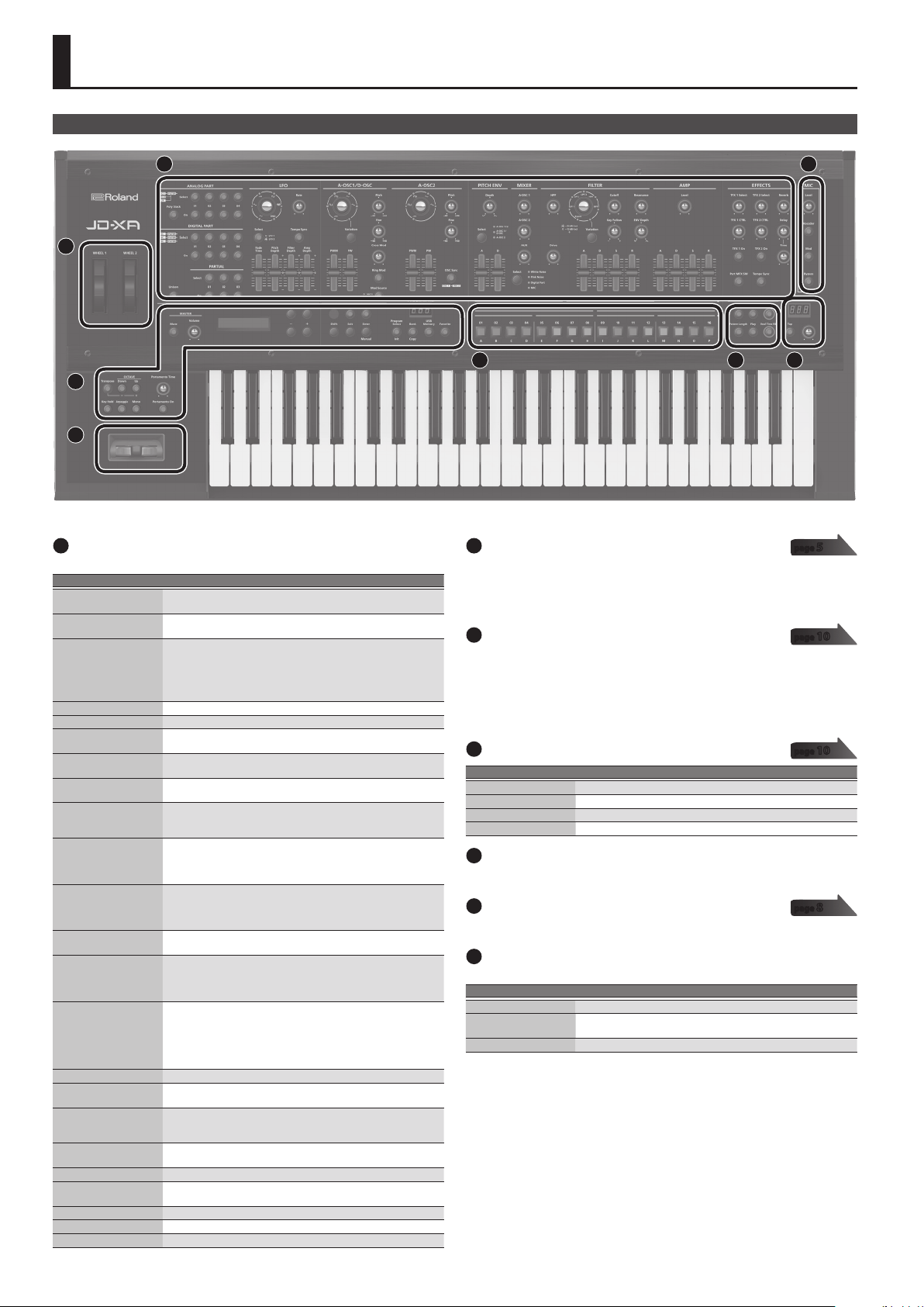
Top Panel
Rear Panel
Introduction
Turning On/O the Power
Selecting a Sound (Program)
Selecting a Part
Editing a Sound (Program)
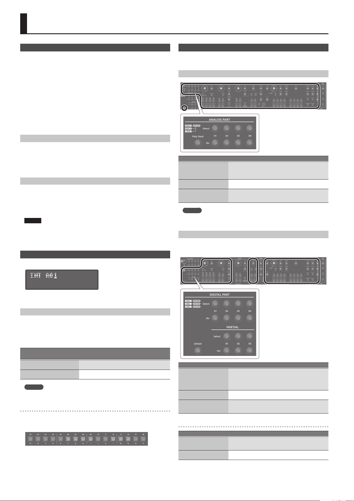
Editing an Analog Part
Editing a Digital Part
Editing the Eects
Initializing a Sound (Init)
Copying a Sound or Pattern (Copy)
Saving a Program (Write)
Using Favorite Sounds (Programs) (Favorite)
.................................... 2
........................................... 2
........................................... 3
.......................................... 4
............................... 4
............................. 4
....................................... 4
............................. 5
................................. 5
................................... 6
..................................... 6
................................ 7
............................... 7
Recording (Pattern Sequencer)
Realtime Recording (Real Time REC)
Step Recording (Step REC)
Step Recording 2 (Step REC 2)
Playing Patterns
Erasing an Entire Pattern (Pattern Erase)
Pattern Utility
Saving a Pattern (Write)
...................................... 9
........................................ 9
Playing an Arpeggio
Selecting an Arpeggio Template
Editing an Arpeggio Pattern
Saving an Arpeggio (Write)
Using the Microphone
Adjusting the Input Level
Using the Vocoder
Using a Microphone to Apply Modulation
Outputting the Mic’s Vocal Input
.............................. 8
............................ 8
................................. 9
................................... 9
............................. 9
.............................. 9
................................. 10
............................... 10
..................................... 10
........................ 7
................. 7
......................... 8
....................... 8
.................... 9
.......................... 9
.................. 10
.......................... 10
Controlling Your Performance
Changing the Pitch/Applying Vibrato
(Pitch Bend/Modulation Lever)
Using an Assigned Function to Modify the Sound (WHEEL 1/2)
Using External Pedals (HOLD/CTRL 1/CTRL 2)
Connecting External Devices
Using the JD-XA as a MIDI Controller
Connecting an Analog Synthesizer via the CV/GATE Output
Connecting a Computer via USB
Overall Settings for the JD-XA
Accessing the Menu Screens
Making System Settings (SYSTEM)
Saving the System Settings
Convenient Functions (UTILITY)
Formatting a USB Flash Drive (USB MEM FORMAT)
Restoring Backup Data from a USB Flash Drive
Returning to the Factory Settings (FACTORY RESET )
Making the Power Automatically Turn O After a Time (Auto O)
Customizing the Knob and Slider Illumination (LED CUSTOMIZE)
List of Shortcut Keys
Error Messages
Main Specications
................................... 16
........................................ 17
.................................... 17
USING THE UNIT SAFELY
IMPORTANT NOTES
Placing the JD-XA on a Stand
.................................... 18
.......................... 10
. . . . . . . . . . . . . . . . . . . . . . . . . . . 10
................ 10
........................... 11
...................... 11
.......................... 11
.......................... 12
............................. 12
........................ 12
.............................. 14
.......................... 14
............ 14
............... 15
........... 15
............................... 18
............................ 18
.. 10
..... 11
15
. 15
Owner’s Manual
Read this rst. It explains the basic things you need to know in order to use the JD-XA.
PDF Manual
5Parameter Guide
This explains all parameters of the JD-XA.
5MIDI Implementation
This is detailed information about MIDI messages.
Before using this unit, carefully read “USING THE UNIT SAFELY” and “IMPORTANT NOTES” (leaet “USING THE UNIT SAFELY” and Owner’s Manual (p. 18)). After reading, keep the document(s) including
those sections where it will be available for immediate reference.
© 2015 Roland Corporation
(this document)
(download from the Web)
(English)
(English)
To obtain the PDF manual
Enter the following URL in your computer.
1.
http://www.roland.com/manuals/
Choose “JD-XA” as the product name.
2.
I
Page 2
Panel Descriptions
Top Panel
2
3
1
3
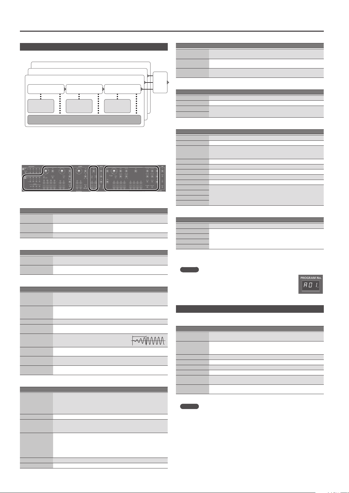
Common section
1
Here you can make the following settings for the JD-XA.
Controller Explanation
MASTER [Mute] button
MASTER [Volume] knob
Display
Cursor [K] [J] buttons Move the cursor left/right.
[-] [+] buttons Change the value at the cursor position.
[MIDI CTRL] button
[Menu] button
[Write] button
[Shift] button
[Exit] button
[Enter] (Manual) button
PROGRAM No. display
[Program Select] (Init)
button
[Bank] (Copy) button
[USB Memory] button Lets you use programs that are stored on a USB ash drive.
[Favorite] button
[Transpose] button
OCTAVE [Down] [Up]
buttons
[Key Hold] button Holds the notes that are currently pressed on the keyboard.
[Arpeggio] button
[Mono] button Switches the part’s mono/poly setting (only for a digital part).
[Portamento Time] knob Species the portamento time.
[Portamento On] button Turns portamento on/o.
Mutes the sound from the OUTPUT L/MONO and R jacks and the
ANALOG DRY jack.
Adjusts the volume of the sound that’s output from the OUTPUT L/
MONO and R jacks and the PHONES jack.
Shows various information for the operation.
* The explanations in this manual include illustrations that depict
what should typically be shown by the display. Note, however, that
your unit may incorporate a newer, enhanced version of the system
(e.g., includes newer sounds), so what you actually see in the display
may not always match what appears in the manual.
Lets you use the JD-XA’s controllers to control an external MIDI device.
“Using the JD-XA as a MIDI Controller” (p. 11)
&
Accesses the Menu screen.
“Accessing the Menu Screens” (p. 12)
&
Saves the edited data.
“Saving a Program (Write)” (p. 7)
&
When used in conjunction with other buttons or knobs, lets you view
parameters or edit dierent parameters.
“List of Shortcut Keys” (p. 16)
&
Returns you to the previous screen.
In some screens, this cancels the operation currently being executed.
When used in conjunction with a knob, lets you view the current
parameter without changing its value.
Press this to conrm a value or execute an operation.
If you press this button while holding down the [Shift] button, the
positions of all knobs and sliders are applied to the sound you’re
editing (Manual).
Displays the currently selected program number (
If the program or pattern has been edited, the decimal point is lit.
Lets you use the [01]–[16] buttons to select programs.
If you hold down the [Shift] button and press this button, the Init
Menu screen appears.
“Initializing a Sound (Init)” (p. 7)
&
Press this button to make it blink, and then use the [01] (A)–[16]
(P) buttons to select the program bank. When you’ve selected the
program bank, the button goes dark, returning to its previous state.
If you hold down the [Shift] button and press this button, the Copy
Menu screen appears.
“Copying a Sound or Pattern (Copy)” (p. 7)
&
Lets you register and recall frequently-used program numbers as
favorites (Favorite)
Turns the transpose function on/o.
Hold down the [Transpose] button and use the OCTAVE [Down] [Up]
buttons to specify the amount of transposition.
Switch the octave of the keyboard.
Turns the arpeggio function on/o.
“Playing an Arpeggio” (p. 9)
&
A01.–P16.
4
5 6 7
Synthesizer section
2
ANALOG PART
Here you can select and edit an analog part.
DIGITAL PART
Here you can select and edit a digital part.
Controllers
3
Pitch bend/modulation lever
You can use this to modify the pitch or to apply vibrato.
Wheel 1/2
You can assign MIDI messages of your choice to these wheels and use them as
controllers.
“Making System Settings (SYSTEM)” (p. 12)
&
MIC
4
Controller Explanation
[Level] knob Species the volume of the microphone.
[Vocoder] button The microphone is used as a vocoder.
[Mod] button The microphone is used for modulation.
[Bypass] button The sound of the microphone is output without change.
[01]–[16] buttons
5
Use these buttons to select programs or banks, or when recording on the pattern
sequencer.
PATTERN SEQ (pattern sequencer)
6
Here you can record your keyboard performance and knob operations, and play
).
them back repeatedly.
TEMPO
7
Here you can specify the tempo of the arpeggio or the pattern sequencer.
Controller Explanation
TEMPO display Displays the tempo value.
[Tap] button
[TEMPO] knob Species the tempo.
You can change the tempo by pressing the [Tap] button three times or
more at quarter-note intervals of the desired tempo.
page
page
page
page
5
10
10
8
2
Page 3
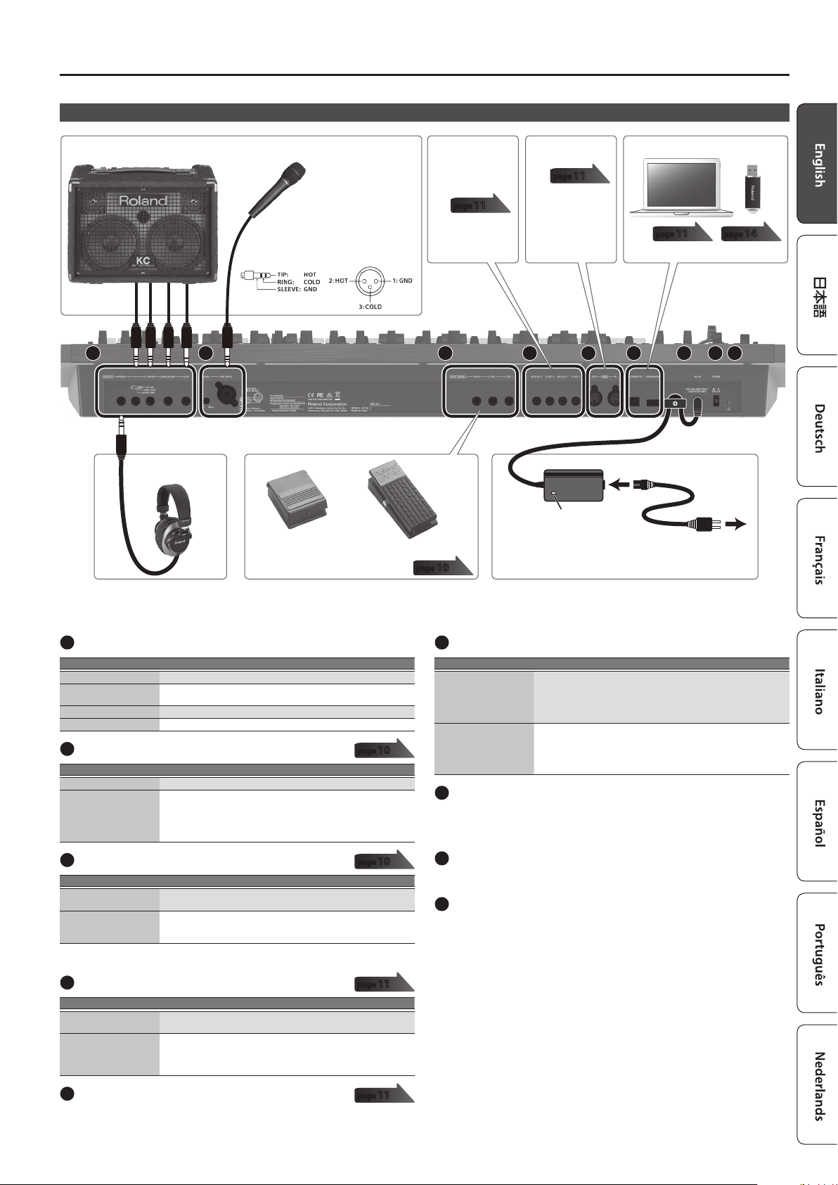
Rear Panel
Panel Descriptions
Amplied Speakers
Microphone
This instrument is equipped
*
with balanced (XLR/TRS)
type jacks. Wiring diagrams
for these jacks are shown
below. Make connections
after rst checking the
wiring diagrams of other
equipment you intend to
connect.
Here you can
connect an analog
synthesizer that is
equipped with a CV/
GATE input jack.
page
11
For connecting MIDI
device.
page
11
Computer USB ash drive
page
11
A B C D E F G H I
Headphones
Pedal switch
(DP-2; sold separately)
Expression pedal (EV-5; sold
separately)
page
10
Place the AC adaptor so the side with the indicator (see illustration) faces
*
upwards and the side with textual information faces downwards. The
indicator will light when you plug the AC adaptor into an AC outlet.
AC adaptor
Indicator
Power Cord
AC Outlet
page
14
* To prevent malfunction and equipment failure, always turn down the volume, and turn o all the units before making any connections.
OUTPUT jacks
A
Jack Explanation
PHONES jack You can connect a set of headphones here.
L/MONO, R jacks
ANALOG DRY jack Outputs the dry sound (without eects) of the analog parts.
CLICK jack Outputs the metronome click sound.
MIC INPUT
B
Controller/jack Explanation
[LEVEL] knob Adjusts the input level of the MIC INPUT jack.
MIC INPUT jack
FOOT PEDAL jacks
C
Jack Explanation
HOLD jack
CTRL 1/2 jacks
* Use only the specied expression pedal (EV-5; sold separately). By connecting any other
expression pedals, you risk causing malfunction and/or damage to the unit.
CV/GATE jacks
D
Jack Explanation
GATE OUT 1/2 jacks
CV OUT 1/2 jacks
Connect these jacks to your amplied speakers.
Use the L/MONO jack if you’re outputting in monaural.
page
Connect a microphone here.
The MIC INPUT jack supports both XLR type and TRS type plugs. The
XLR type connection supports 48 V phantom power, allowing you
to connect a condenser microphone that supports phantom power
(phantom power: DC 48 V, 10 mA max.).
page
You can connect a pedal switch (such as the DP-2; sold separately)
here and use it as a hold pedal.
You can connect an expression pedal (EV-5; sold separately) or pedal
switch (such as the DP-2; sold separately) here and use it to control
various parameters or operations.
page
These jacks output note-on/o.
They output +5 V.
These jacks output pitch.
If you’ve specied a transpose or octave shift setting, the voltage
changes according to the setting.
These jacks support OCT/V (Hz/V is not supported).
10
10
11
USB port
F
Port Explanation
USB COMPUTER port
USB MEMORY port
DC IN jack
G
If the JD-XA is connected to your computer via a commercially
available USB 2.0 cable, you can synchronize it with a DAW on your
computer via USB MIDI, and record the sound of the JD-XA into your
DAW via USB audio.
“Connecting a Computer via USB” (p. 11)
&
You can connect a USB ash drive here.
You can use a USB ash drive to save programs and back up data.
“Restoring Backup Data from a USB Flash Drive” (p. 15)
&
* Use a USB ash drive sold by Roland. We cannot guarantee
operation if other products are used.
Connect the included AC adaptor here.
* To prevent the inadvertent disruption of power to your unit (should the plug be pulled out
accidentally), and to avoid applying undue stress to the jack, anchor the power cord using the
cord hook, as shown in the illustration.
[POWER] switch
H
This turns the power on/o.
“Turning On/O the Power” (p. 4)
&
Ground terminal
I
Depending on the circumstances of a particular setup, you may experience a
discomforting sensation, or perceive that the surface feels gritty to the touch
when you touch this device, microphones connected to it, or the metal portions
of other objects, such as guitars. This is due to an innitesimal electrical charge,
which is absolutely harmless. However, if you are concerned about this, connect the
ground terminal (see gure) with an external ground. When the unit is grounded, a
slight hum may occur, depending on the particulars of your installation. If you are
unsure of the connection method, contact the nearest Roland Service Center, or an
authorized Roland distributor, as listed on the “Information” page.
Unsuitable places for connection
5Water pipes (may result in shock or electrocution)
5Gas pipes (may result in re or explosion)
5Telephone-line ground or lightning rod (may be dangerous in the event of lightning)
MIDI connectors (IN/OUT)
E
page
11
These connectors can be connected to other MIDI devices to receive and transmit
MIDI messages.
3
Page 4
Introduction
Turning On/O the Power
* Once everything is properly connected (p. 3), be sure to follow the procedure below to
turn on their power. If you turn on equipment in the wrong order, you risk causing malfunction
or equipment failure.
* Before turning the unit on/o, always be sure to turn the volume down. Even with the volume
turned down, you might hear some sound when switching the unit on/o. However, this is
normal and does not indicate a malfunction.
Before turning on the JD-XA’s power, consider these two questions:
1.
5Are your speakers or headphones connected correctly?
5Is the connected equipment powered-o?
Turn the MASTER [Volume] knob on the top panel all the way to the left.
2.
Turn on the [POWER] switch located on the rear panel.
3.
* This unit is equipped with a protection circuit. A brief interval (a few seconds) after turning the
unit on is required before it will operate normally.
Switch on power to the connected equipment, and raise the volume to an
4.
appropriate level.
Turning O the Power
Before turning o the power, consider these two questions:
1.
5Have you minimized the volume of the connected equipment?
5Have you saved any sounds or patterns that you created?
Turn o the power for all connected audio devices.
2.
Turn o the [POWER] switch of the JD-XA.
3.
About the Auto O Function
The power to this unit will be turned o automatically after a predetermined
amount of time has passed since it was last used for playing music, or its buttons or
controls were operated (Auto O function).
If you do not want the power to be turned o automatically, disengage the Auto O
function.
“Making the Power Automatically Turn O After a Time (Auto O)” (p. 15)
&
NOTE
5Any settings that you are in the process of editing will be lost when the power is
turned o. If you have any settings that you want to keep, you should save them
beforehand.
5To restore power, turn the power on again.
“Turning On/O the Power” (p. 4)
&
Selecting a Sound (Program)
Selecting a Part
Each analog part is monophonic.
The [Poly Stack] button lets you make the four monophonic analog parts operate in
four-voice polyphony (p. 5).
Selecting an ANALOG Part
Function Operation
Select a part to edit
Select a part to play from the
keyboard
Part mute
MEMO
Since the analog synth parts consist of analog circuitry, their sound may be
aected by the temperature, the power supply, and the environment in which the
instrument is located.
Selecting a DIGITAL Part
The digital parts are polyphonic.
Each part is a three-partial SuperNATURAL synthesizer, and you can use four such
parts.
Press a Select [01]–[04] button to make it light.
You can select multiple parts by pressing multiple buttons
simultaneously.
You can’t select analog par ts and digital parts simultaneously.
Press an On [01]–[04] button to make it light.
If the button is unlit, that part won’t produce sound.
Hold down the [Shift] button and press an On [01]–[04] button
(blinking: muted / lit: unmuted).
The mute status is shown while you hold down the [Shift] button.
About the program select screen
:
INIT PROGRAM
A program consists of a total of eight parts: four analog parts and four digital parts.
After editing a program, you can save it in internal memory (INT:A01–INT:P16) or on
a USB ash drive (USB:A01–USB:P16).
Selecting a Program
Press the [Program Select] button so it’s lit.
1.
The program select screen appears.
The [01]–[16] button corresponding to the currently selected program number is lit.
Press one of the [01]–[16] buttons.
2.
The program changes.
Saved location
[USB Memory]
Internal memory
([USB Memory] button unlit)
USB ash drive
([USB Memory] button lit)
MEMO
If no USB ash drive is connected, the [USB Memory] button does not light even
if you press it.
Switching banks
In the program select screen, press the [Bank] button to make it light.
1.
The [01] (A)–[16] (P) button corresponding to the currently selected bank number
(A–P) blinks.
Press one of the [01] (A)–[16] (P) buttons.
2.
The bank is switched, and the [Bank] button goes dark.
Use the [01]–[16] buttons to select a program.
3.
Bank
[Bank] 0 [01] (A)–[16] (P)
INT:A–INT:P 01–16
USB:A–USB:P 01–16
Number
[01]–[16]
Function Operation
Select a part to edit
Select a part to play from the
keyboard
Part mute
Press a Select [01]–[04] button to make it light.
You can select multiple parts by pressing multiple buttons
simultaneously.
You can’t select analog par ts and digital parts simultaneously.
Each digital part consists of three partials.
Press an On [01]–[04] button to make it light.
If the button is unlit, that part won’t produce sound.
Hold down the [Shift] button and press an On [01]–[04] button
(blinking: muted / lit: unmuted).
The mute status is shown while you hold down the [Shift] button.
Selecting a partial (Digital part only)
Function Operation
Select a partial to edit
Play a partial’s sound
Press a Select [01]–[03] button to make it light.
You can select multiple partials by pressing multiple buttons
simultaneously.
Press an On [01]–[03] button to make it light.
If the button is unlit, that partial won’t produce sound.
4
Page 5
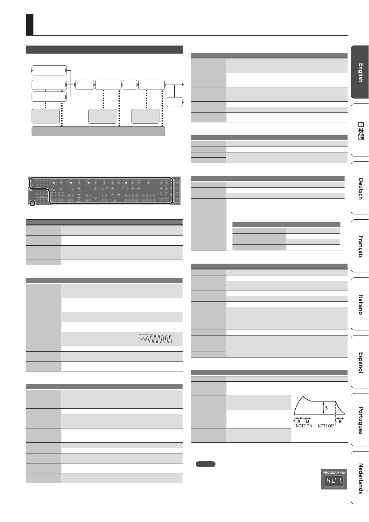
Editing a Sound (Program)
Editing an Analog Part
ANALOG PART
AUX
A-Filter
A-OSC2
Pitch ENV
1/2
For details of the overall structure, refer to the “JD-XA Structure Diagram”
&
inside the front cover.
Filter ENV
LFO 1/2
When you move a controller, the corresponding parameter is shown in the screen
(the value changes in tandem with the controller).
If you move the controller while holding down the [Exit] button, the parameter is
displayed without changing its value; this lets you check the current value.
ANALOG PART
Controller Explanation
Select [01]–[04]
buttons
On [01]–[04]
buttons
[Poly Stack] button
[Unison] button Selects unison. This is available only if poly stack is on.
Select the part that is edited by panel operations.
Select the part that is played from the keyboard.
Lets you use the four analog parts as one four-voice poly part.
If the Poly Stack is on, only one part is on.
Use the On [01]–[04] buttons to select the parts that are used for poly stack.
LFO
Controller Explanation
Wave knob
[Rate] knob
[Select] button
[Tempo Sync]
button
[Fade Time] slider
[Pitch Depth] slider Allows the LFO to modulate the A-OSC pitch, producing a vibrato eect.
[Filter Depth] slider
[Amp Depth] slider
Selects the LFO waveform.
(Triangle wave), R (Sine wave),T (Sawtooth wave), U (Square wave),
S
(Sample and Hold), RND (Random wave)
W
Determines the speed of the LFO modulation.
* If the [Tempo Sync] button is on, you can specify the LFO modulation
speed in terms of a note value relative to the tempo.
Selects the LFO that will be edited.
LFO1 (unlit), LFO2 (lit)
Synchronizes the LFO modulation speed to the tempo.
Species the time from when the tone
sounds until the LFO reaches its maximum
amplitude.
Allows the LFO to modulate the FILTER CUTOFF (cuto frequency),
producing a wah eect.
Allows the LFO to modulate the AMP LEVEL (volume), producing a tremolo
eect.
A-OSC1
Controller Explanation
Wave knob
[Variation] button Not used with analog parts.
[PWM] slider
[PW] slider
[Pitch] knob Species the oscillator pitch.
[Fine] knob Fine adjustment of the oscillator pitch.
[Cross Mod] knob
[Ring Mod] button
[Mod Source]
button
Selects the oscillator waveform.
(Sawtooth wave), U (Square wave), V (Asymmetrical square wave),
T
(Triangle wave), R (Sine wave),
S
Variation (not used with A-OSC)
When V (asymmetrical square wave) is selected as the oscillator
waveform
Species the amount of LFO modulation applied to PW.
When V (asymmetrical square wave) is selected as the oscillator
waveform
Species the pulse width.
Species the amount by which the A-OSC2/AUX waveform modies the
frequency of A-OSC1.
Gives the sound a metallic character by multiplying A-OSC1 and A-OSC2/
AUX.
Selects the modulation source waveform (A-OSC2/AUX).
HPFDRIVEA-OSC1
AMP
AMP ENV
MFX
A-OSC2
Controller Explanation
Wave knob
DRY
OUT
[PWM] slider
[PW] slider
[Pitch] knob Species the oscillator pitch.
[Fine] knob Fine adjustment of the oscillator pitch.
[OSC Sync] button
Selects the oscillator waveform.
(Sawtooth wave), U (Square wave), V (Asymmetrical square wave),
T
(Triangle wave), R (Sine wave),
S
When V (asymmetrical square wave) is selected as the oscillator
waveform
Species the amount of LFO modulation applied to PW.
When V (asymmetrical square wave) is selected as the oscillator
waveform
Species the pulse width.
Creates a complex waveform by forcibly returning A-OSC1 to the beginning
of its cycle in synchronization with the cycle of A-OSC2.
PITCH ENV
Controller Explanation
[Depth] knob Species the direction and amount of the pitch change.
[Select] button Selects the pitch envelope editing target.
[A] slider
[D] slider
These sliders operate similarly to the [A] [D] sliders of the AMP section (they
aect the pitch rather than the volume).
MIXER
Controller Explanation
[A-OSC 1] knob Species the A-OSC1 volume.
[A-OSC 2] knob Species the A-OSC2 volume.
[AUX] knob Species the AUX volume.
[Select] button
Species the AUX source.
White Noise, Pink Noise, Digital Part, MIC
* The digital part that can be selected as the AUX source will be the same
part number as the analog part. It is not possible to select a dierent
part.
Analog part Digital part selected
Analog part 01 Digital part 01
Analog part 02 Digital part 02
Analog part 03 Digital part 03
Analog part 04 Digital part 04
FILTER
Controller Explanation
[HPF] knob Species the cuto frequency of the high-pass lter.
[Drive] knob Adjusts the drive.
Filter type select
knob
[Variation] button Not used with analog parts.
[Cuto] knob Species the cuto frequency.
[Resonance] knob Species the resonance.
[Key Follow] knob
[ENV Depth] knob Species the direction and amount of the change in cuto frequency.
[A] slider
[D] slider
[S] slider
[R] slider
Selects the lter type.
LPF1–3 (Low Pass Filter), HPF (High Pass Filter), BPF (Band Pass Filter)
Allows the lter cuto frequency to vary according to the key that you play.
If the knob is turned toward the right, the cuto frequency becomes higher
as you play higher notes.
If the knob is turned toward the left, the cuto frequency becomes lower as
you play lower notes.
These sliders operate similarly to the [A] [D] [S] [R] sliders of the AMP section
(they aect the cuto frequency rather than the volume).
AMP
Controller Explanation
[Level] knob Species the AMP Level.
[A] slider
(Attack time)
[D] slider
(Decay time)
[S] slider
(Sustain level)
[R] slider
(Release time)
EFFECTS
“Editing the Eects” (p. 6)
&
Species the time from the moment
you press the key until the maximum
volume is reached.
Species the time from when the
maximum volume is reached, until it
decays to the sustain level.
Species the volume level that will be
maintained from when the attack and
decay times have elapsed until you
release the key.
Species the time from when you
release the key until the volume reaches
its minimum value.
MEMO
5If the program has been edited, the decimal point of the program
number is lit.
5The edited sound is saved in the program.
“Saving a Program (Write)” (p. 7)
&
5Some parameters can be edited without using a controller.
For details, refer to “Parameter Guide (English)” (PDF).
&
5
Page 6
Editing a Sound (Program)
Editing a Digital Part
DIGITAL PART (SuperNATURAL Synth)
Partial 3
Partial 2
Partial 1
WG TVF TVA
Pitch ENV Filter ENV AMP ENV
LFO
For details of the overall structure, refer to the “JD-XA Structure Diagram”
&
inside the front cover.
When you move a controller, the corresponding parameter is shown in the screen
(the value changes in tandem with the controller).
If you move the controller while holding down the [Exit] button, the parameter is
displayed without changing its value; this lets you check the current value.
* Digital parts do not use the A-OSC2 and MIXER sections.
DIGITAL PART
Controller Explanation
Select [01]–[04]
buttons
On [01]–[04]
buttons
[Unison] button Selects unison.
PARTIAL
Controller Explanation
Select [01]–[03]
buttons
On [01]–[03]
buttons
LFO
Controller Explanation
Wave knob
[Rate] knob
[Select] button Not used with digital parts.
[Tempo Sync]
button
[Fade Time] slider
[Pitch Depth] slider
[Filter Depth] slider
[Amp Depth] slider
D-OSC
Controller Explanation
Wave knob
[Variation] button Selects the variation waveform as the waveform of the oscillator.
[PWM] slider
[PW] slider
[Pitch] knob Species the oscillator pitch.
[Fine] knob Fine adjustment of the oscillator pitch.
Select the part that is edited by panel operations.
Select the part that is played from the keyboard.
Select the partial that is edited by panel operations.
Select the partials that produce sound.
Selects the LFO waveform.
(Triangle wave), R (Sine wave),T (Sawtooth wave), U (Square wave),
S
(Sample and Hold), RND (Random wave)
W
Determines the speed of the LFO modulation.
* If the [Tempo Sync] button is on, you can specify the LFO modulation
speed in terms of a note value relative to the tempo.
Synchronizes the LFO modulation speed to the tempo.
Species the time from when the tone
sounds until the LFO reaches its maximum
amplitude.
Allows the LFO to modulate the pitch of the partial, producing a vibrato
eect.
Allows the LFO to modulate the FILTER CUTOFF (cuto frequency),
producing a wah eect.
Allows the LFO to modulate the AMP LEVEL (volume), producing a tremolo
eect.
Selects the oscillator waveform.
(Sawtooth wave), U (Square wave), V (Asymmetrical square wave),
T
(Triangle wave), R (Sine wave),
S
Variation (Press the [Variation] button and use the [-] [+] buttons to select
the variation waveform.)
When V (asymmetrical square wave) is selected as the oscillator
waveform
Species the amount of LFO modulation applied to PW.
When V (asymmetrical square wave) is selected as the oscillator
waveform
Species the pulse width.
When SuperSaw is selected as the oscillator waveform
Species the detune.
MFX
Controller Explanation
[Cross Mod] knob Not used with digital parts.
[Ring Mod] button
[Mod Source]
button
Produces a more complex waveform by multiplying Partial 1’s OSC by Partial
2’s OSC.
Not used with digital parts.
PITCH ENV
Controller Explanation
[Depth] knob Species the direction and amount of the pitch change.
[Select] button Not used with digital parts.
[A] slider
[D] slider
These have the same operation as the PITCH ENV [A] [D] sliders for an analog
part.
FILTER
Controller Explanation
[HPF] knob Species the cuto frequency of the high-pass lter.
[Drive] knob Not used with digital parts.
Filter type select
knob
[Variation] button Selects the variation type as the type of lter.
[Cuto] knob Species the cuto frequency.
[Resonance] knob Species the resonance.
[Key Follow] knob Allows the lter cuto frequency to vary according to the key that you play.
[ENV Depth] knob Species the direction and amount of the change in cuto frequency.
[A] slider
[D] slider
[S] slider
[R] slider
Selects the lter type.
The indicator shows the slope of the lter.
-12 dB/oct (unlit), -24 dB/oct (lit)
These have the same operation as the FILTER [A] [D] [S] [R] sliders for an
analog part.
AMP
Controller Explanation
[Level] knob Species the AMP Level.
[A] slider
[D] slider
[S] slider
[R] slider
EFFECTS
“Editing the Eects” (p. 6)
&
These have the same operation as the AMP [A] [D] [S] [R] sliders for an analog
part.
MEMO
5If the program has been edited, the decimal point of the program
number is lit.
5The edited sound is saved in the program.
“Saving a Program (Write)” (p. 7)
&
5Some parameters can be edited without using a controller.
For details, refer to “Parameter Guide (English)” (PDF).
&
Editing the Eects
For details of the overall structure, refer to the “JD-XA Structure Diagram”
&
inside the front cover.
Controller Explanation
[TFX 1/2 Select]
knob
[TFX 1/2 CTRL]
knob
[TFX 1/2 On] button Turns TFX1/2 on/o.
[Reverb] knob Species the volume of reverb.
[Delay] knob Species the volume of delay.
Delay [Time] knob Species the delay time.
[Part MFX SW]
button
[Tempo Sync]
button
For details on the parameters, refer to “Parameter Guide (English)” (PDF).
&
MEMO
Eect settings are saved in the program.
“Saving a Program (Write)” (p. 7)
&
Selects the TFX1/2 eect type.
Globally controls TFX1/2.
Global control is a function that lets you use a single knob to control
multiple parameters that make up the eect.
Turns the Part MFX on/o.
Synchronizes the Part MFX and delay to the tempo.
If this is “o,” the Tempo Sync setting of each eect is used.
6
Page 7
Initializing a Sound (Init)
Here’s how to initialize the settings of a program, part, partial, or pattern.
Hold down the [Shift] button and press the [Program Select/Init] button.
1.
The INIT screen appears.
Use the cursor [K] [J] buttons and the [-] [+] buttons to specify what you
2.
want to initialize.
Settings to
initialize
[-] [+]
PROGRAM Program settings
PAR T Part settings (including MFX, the MIDI channel)
PARTIAL Partial settings (if a digital part is selected)
PATTERN Pattern
Press the [Enter] button.
3.
A conrmation message appears.
If you decide to cancel, press the [Exit] button.
Press the [Enter] button.
4.
The screen indicates “Completed!” and initialization is executed.
Explanation
Copying a Sound or Pattern (Copy)
Here’s how to copy settings from a part, partial, or pattern that’s saved in another
program, or from an INTEGRA-7 or FA-06/08 tone.
Hold down the [Shift] button and press the [Bank] (Copy) button.
1.
The COPY screen appears.
Use the cursor [K] [J] buttons to select the data that you want to copy, and
2.
press the [Enter] button.
Settings to copy
Cursor [K] [J]
Part Part settings (including MFX, excluding the MIDI channel)
Partial Partial settings (only if a digital part is selected)
Pattern Pattern
Tone
Explanation
Tone (only if a USB ash drive is connected)
Copying tone settings
“SuperNATURAL synth tones” from the INTEGRA-7 or FA-06/08 can be used by
a digital part of the JD-XA.
Export/save the “SuperNATURAL synth tone” data from an INTEGRA-7 or FA06/08 to your USB ash drive.
Importing that data into the JD-XA is referred to as copying the tone settings.
The data to be imported must be saved to the IMPORT folder of the USB ash
drive.
For details, refer to “The folder structure of a USB ash drive” (p. 14).
&
NOTE
If “Part” is selected as the data to copy, the MIDI channel is not copied.
Use the [-] [+] buttons to select the copy-source data, and then press the
3.
[Enter] button (select Source).
The parameters dier depending on the copy-source you selected.
Repeat this procedure as many times as needed.
MEMO
Depending on the parameters, you can also use [Bank], [01]–[16], and each part’s
Select [01]–[04] and Partial [01]–[03] buttons.
Use the [-] [+] buttons to select the copy-destination, and then press the
4.
[Enter] button (select Destination).
The parameters dier depending on what you’re copying.
Repeat this procedure as many times as needed.
MEMO
Depending on the parameters, you can also use each part’s On [01]–[04] and
Partial [01]–[03] buttons.
Press the [Enter] button.
5.
A conrmation message appears.
If you decide to cancel, press the [Exit] button.
Press the [Enter] button.
6.
The screen indicates “Completed!” and the copy is executed.
Saving a Program (Write)
A sound that you create will loose if you move the knobs or if you select a dierent
program. It will also be lost if you power-o the JD-XA.
When you’ve created a sound that you like, you should save it as a program.
Press the [Write] button.
1.
Use the Cursor [K] [J] buttons to select “PROGRAM,” and then press the
2.
[Enter] button.
The name input screen appears.
Editing a Sound (Program)
When you’ve nished specifying the name, press the [Enter] button.
4.
Use the [-] [+] buttons to select the save-destination.
5.
If you want to save to a USB ash drive, press the [USB Memory] button to make it
light.
You can also use the [Bank] and [01]–[16] buttons to select the save-destination.
* If you specify a number in which data is already saved, the program name is shown in the
lower line. If you save to this number, the previous data is erased and overwritten by the new
program.
Press the [Enter] button.
6.
A conrmation message appears.
If you decide to cancel, press the [Exit] button.
Press the [Enter] button.
7.
A screen indicating “Completed!” appears, and the data is saved.
* NEVER turn the power o while you are saving settings.
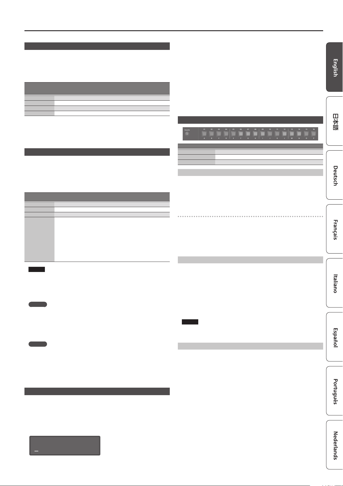
Using Favorite Sounds (Programs) (Favorite)
Controller Explanation
[Favorite] button Use these button to register and recall your favorite sounds (programs).
[01]–[16] buttons Use these buttons to select Favorite 01–16.
[Bank] button Use this button to select the Favorite bank (A–P).
Selecting a Favorite
Press the [Favorite] button so it’s lit.
1.
The [01]–[16] buttons become the Favorite select buttons.
Press one of the [01]–[16] buttons to select a favorite sound.
2.
If you press a button in which nothing is registered, the screen indicates “Not
Registered!”
Switching the Favorite bank
When the [Favorite] button is lit, press the [Bank] button.
1.
The [01] (A)–[16] (P) button corresponding to the currently selected bank number
(A–P) blinks.
Press one of the [01] (A)–[16] (P) buttons.
2.
The bank is switched, and the [Bank] button goes dark.
Use the [01]–[16] buttons to select a favorite.
3.
Registering a Favorite
Select a program that you want to register as a favorite.
1.
Press the [Favorite] button so it’s lit.
2.
Select the bank in which you want to register the favorite.
3.
“Switching the Favorite bank” (p. 7)
&
Hold down the [Favorite] button and press the favorite number ([01]–[16]
4.
buttons) that you want to register.
The currently selected program is registered to that button.
While you hold down the [Favorite] button, the [01]–[16] buttons in which you
saved favorites are lit; buttons in which you did not save favorites are blinking.
NOTE
If you’ve edited a program, save that program rst before registering it as a
favorite.
“Saving a Program (Write)” (p. 7)
&
Deleting a Favorite
In the Menu screen, choose “FAVORITE UTIL” and press the [Enter] button.
1.
The FAVORITE UTIL screen also appears if you hold down the [Shift] button and
press the [Favorite] button.
Use the cursor [K] [J] buttons to select a favorite bank.
2.
[-] [+]
Use the
3.
You can also use the [01]–[16] buttons to select a favorite to delete.
Press the [Enter] button to delete the favorite that is shown.
4.
buttons to select the favorite that you want to delete.
PROG NAME: [Ent]
INIT PROGRAM
Use the cursor [K] [J] buttons and [-] [+] buttons to edit the characters.
3.
7
Page 8

Recording (Pattern Sequencer)
The pattern sequencer lets you record keyboard performance and knob operations,
and play them back repeatedly.
When you record, the currently selected part is recorded.
Controller Explanation
[Scale] button
[Erase] button Erase a recorded pattern or a portion of a pattern.
[Step REC] button Lets you record your keyboard playing one step at a time.
[Pattern Length]
button
[Play] button Play or stop the pattern.
[Real Time REC]
button
Changes the length of one step. The indicators at the left of the button show
the setting.
5The [01]–[12] buttons correspond to a recording input range of two beats,
allowing you to enter 16th note triplets.
5The [01]–[12] buttons correspond to a recording input range of one
measure, allowing you to enter 8th note triplets.
5The [01]–[16] buttons correspond to a recording input range of two beats,
allowing you to enter 32nd notes.
5The [01]–[16] buttons correspond to a recording input range of one
measure, allowing you to enter 16th notes.
Changes the number of measures in the pattern. You can create a pattern up
to four measures long.
Use the [01]–[04] buttons to specify the length.
For some Scale settings, use the [01]–[08] buttons to specify the length.
Create a pattern by recording your performance of the keyboard and
controllers in real time.
Realtime Recording (Real Time REC)
Here’s how to create a pattern by recording your performance of the keyboard
and controllers in real time. Your performance is recorded by layering it onto the
selected pattern.
Use the ANALOG PART or DIGITAL PART On [01]–[04] buttons to turn on the
1.
part that you want to record.
Press the [Real Time REC] button (REC STANDBY).
2.
Make settings for realtime recording.
3.
Use the cursor [K] [J] buttons to select a parameter, and use the [-] [+] buttons to
edit the setting.
Parameter
Cursor [K] [J]
Cnt In (Count In)
* This is shown
only during REC
STANDBY.
Input Qtz
(Input Quantize)
Reso (Resolution)
Strength
Rate
Loop Rec
Tempo Rec Species whether tempo changes are recorded (ON) or not recorded (OFF).
Click Switch Turns the click sound on/o.
For details on the parameters, refer to “Parameter Guide (English)” (PDF).
&
Press the [Play] button to start recording.
4.
During playback, you can also press the [Real Time REC] button to start recording.
Play the keyboard.
5.
Movements of the knobs and wheels are also recorded.
Press the [Real Time Rec] button to stop recording.
6.
Click Settings
Press the [Menu] button.
1.
Select “SYSTEM” and then press the [Enter] button.
2.
Choose the CLICK parameter (p. 13), and use the [-] [+] buttons to change
3.
the value.
Press the [Exit] button several times to return to the program select screen.
4.
Save the system parameters if necessary.
“Saving the System Settings” (p. 14)
&
Explanation
Selects the way in which recording is started.
OFF, 1 MEAS, 2 MEAS, WAIT NOTE
Quantize is a function that automatically corrects inaccuracies in the timing
at which you play the keyboard, tightening-up the rhythmic accuracy.
You can apply the quantize function during realtime recording. This setting
species whether quantize will be applied during recording.
OFF, GRID, SHFL (shue)
Species the note timing value at which quantization is applied.
GRID: 1/32 (
SHFL: 1/16 (
This setting is used with grid quantize. It species the degree to which your
notes are moved to precise intervals of the note values specied by the Reso
setting. If this is set to “100%,” the notes that you record are moved all the
way to exact intervals of the specied Reso. With lower percentages, less
correction is applied. If this is set to “0%,” the timing is not corrected at all.
0–100%
Use this setting when applying shue quantize.
With a setting of “50%” the notes are spaced at equal intervals. As you
increase this setting, you’ll get an increasingly “bouncy” feel as though the
notes were dotted.
Specify whether Real Time REC turns o (OFF) or stays on (ON) when you
move to the next loop after recording your performance.
)–1/4 ( )
)–1/8 ( )
Erasing Only a Portion of a Phrase
During playback or recording, press the [Erase] button (Erase Mode).
1.
The button is lit, allowing you to erase notes. The Erase screen appears.
Use the [-] [+] buttons to choose what you want to erase, and then press the
2.
[Enter] button.
The chosen data is erased while you hold down the button.
MEMO
In erase mode, notes of the key you hold down are erased while you continue
holding down that key.
If you hold down two keys, all notes between those two keys are erased.
Press the [Erase] button once again.
3.
The button goes dark and the JD-XA returns to its previous state.
Changing the Tempo
“TEMPO” (p. 2)
&
MEMO
The tempo is saved for each individual program.
“Saving a Program (Write)” (p. 7)
&
Step Recording (Step REC)
Here’s how to create a pattern by recording your keyboard performance one step at
a time.
Your new recording replaces the pattern that’s selected.
Controller Explanation
[01]–[16] buttons The button of the part being recorded is blinking.
Use the ANALOG PART or DIGITAL PART On [01]–[04] buttons to select the
1.
part that you want to record.
Press the [Step REC] button.
2.
The [01] button blinks.
The following screen is shown until you stop recording.
STEP REC: 1 1:1
Type 1/16( )
You can use the Cursor [K] [J] buttons to select a parameter, and use the [-] [+]
buttons to edit the value of that parameter.
Parameter
Cursor [K] [J]
Type (Note Type) Species the note value of the notes you’ll input.
Gate Time
(duration of the note)
Velocity
(keyboard dynamics)
Play one note on the keyboard.
3.
Your performance is recorded in step 1; you automatically advance to the next step
and the [02] button lights.
You can record a chord by selecting multiple notes.
Repeat step 3 to record each step.
4.
MEMO
5To erase the data at a step (or to enter a rest), press the [Erase] button.
5To enter a tie, press the [Enter] button.
5To change the step that you’re recording, press one of the [01]–[16] buttons.
5If you want to change the number of measures, press the [Pattern Length] button
and then use the [01]–[04] buttons to specify the length (for some scale settings, use
[01]–[08] to specify the length).
Press the [Step Rec] button to stop recording.
5.
Step Recording 2 (Step REC 2)
While playing or stopped, use the [01]–[16] buttons to record on the selected step
(step recording 2).
Press the [Step REC] button twice to turn Step REC o.
1.
Use the ANALOG PART or DIGITAL PART On [01]–[04] buttons to select the
2.
part that you want to record.
On the keyboard, play the note that you want to record, and then use the
3.
[01]–[16] buttons to turn the step on.
MEMO
5You can also record on a specied step by holding down a note and pressing a [01]–
[16] button to specify the step.
5By turning a knob while holding down one of the [01]–[16] buttons, you can record
the last state of that knob in the specied step.
5Operation of the knob is recorded on the part selected in the PART Select.
Value
[-] [+]
Species the duration of the notes relative to the note type.
5–200%
Real (the actually-played dynamics),
1–127 (xed dynamics)
8
Page 9

Playing an Arpeggio
Playing Patterns
Press the [Play] button.
1.
You can perform the following operations during playback.
Function Operation Explanation
Part Mute
Realtime Erase
To stop, press the [Play] button once again.
2.
[Shift] + each part’s Select [01]–[04]
buttons
1. Press the [Erase] button.
2. Turn on the part that you want to
erase.
3. Use [-] [+] to select what will be
erased.
4. Data is erased while you hold
down the [Enter] button.
Mutes the selected part during
pattern playback (multiple parts can
be selected).
To enter Erase Mode, press the [Erase]
button during playback.
MEMO
If the pattern exceeds 16 steps, hold down the [Shift] button and press the [01]–[04]
buttons to change the range of measures/beats (for some scale settings, use the
[Shift] button + [01]–[08] buttons).
Erasing an Entire Pattern (Pattern Erase)
Here’s how to erase an entire pattern.
Hold down the [Shift] button and press the [Erase] button.
1.
The Erase screen appears.
Use the [-] [+] buttons to select what you want to erase.
2.
Value
[-] [+]
All Erase the entire contents of the pattern.
Track Erase only the data of the selected track.
SysEx Erase only the system exclusive data.
Tempo Erase only the tempo data.
Press the [Enter] button.
3.
The data is erased.
Explanation
Pattern Utility
You can specify a pattern’s output destination settings, and import or export SMF
data.
Press the [Menu] button.
1.
Select “PATTERN UTIL” and then press the [Enter] button.
2.
Use the cursor [K] [J] buttons to select the function that you want to
3.
execute, and then press the [Enter] button.
Function
Cursor [K] [J]
Track Settings
SMF Import
Explanation
Species the output destination of each track.
INT (JD-XA), EXT (external MIDI device), BOTH (both JD-XA and external MIDI
device), OFF (no output)
* This setting is saved in the program together with the pattern.
Imports the specied SMF into the temporary area.
* When you import, the current state of the temporary area is discarded.
The SMF that you want to import must be saved in the IMPORT folder of the
USB ash drive.
SMF data that can be imported:
5Only SMF format 0 is supported.
5Up to four measures of SMF data can be imported. Subsequent data is
not imported.
MEMO
In the SMF Import screen, you can press the [Play] button to
audition the selected SMF.
SMF Export
For details, refer to
&
(p. 14).
Exports the pattern currently in the temporary area as an SMF with the
name you specify.
“The folder structure of a USB ash drive”
Saving a Pattern (Write)
A pattern that you create will loose if you select a dierent program or if you powero the JD-XA.
When you’ve created a pattern that you like, you should save it as a program.
The pattern is saved as a program.
“Saving a Program (Write)” (p. 7)
&
Playing an Arpeggio
Press the [Arpeggio] button to make it light; the arpeggio function turns on.
An “arpeggio” is a performance technique in which the notes of a chord are played
at dierent times.
Selecting an Arpeggio Template
Press the [Arpeggio] button.
1.
The arpeggio function turns on, and the ARPEGGIO screen appears.
By holding down the [Shift] button and pressing the [Arpeggio] button, you can
access the ARPEGGIO screen without turning the function on/o.
Use the Cursor [K] [J] buttons to select “Select Template,” and then press
2.
the [Enter] button.
Use the [-] [+] buttons to select an arpeggio template, and press the [Enter]
3.
button.
Press the [Exit] button to return to the program select screen.
4.
Editing an Arpeggio Pattern
Hold down the [Shift] button and press the [Arpeggio] button.
1.
The ARPEGGIO screen appears without changing the arpeggio on/o state.
ARPEGGIO:
Arp Hold OFF
Select the note number that you want to enter.
4.
You can also use the keyboard to specify the note number and velocity at the same
time.
Specify the velocity that you want to enter.
5.
You can also use the keyboard to specify the note number and velocity at the same
time.
Use the [01]–[16] buttons to turn on the button for the step that you want
6.
to enter.
Steps beyond the number of steps you’ve specied will not turn on.
MEMO
You can press the [Step REC] button to step-record an arpeggio style (use the
keyboard to enter the data one note at a time).
Press the [Exit] button several times to return to the program select screen.
7.
There are also parameters such as Arp Hold and Motif.
For details on the parameters, refer to “Parameter Guide (English)” (PDF).
&
Saving an Arpeggio (Write)
An arpeggio that you create will loose if you select a dierent program or if you
power-o the JD-XA.
When you’ve created an arpeggio that you like, you should save it as a program.
The arpeggio is saved as a program.
“Saving a Program (Write)” (p. 7)
&
Use the Cursor [K] [J] buttons to select “Pattern Edit,” and then press the
2.
[Enter] button.
Use the cursor [K] [J] buttons to select “End Step,” and specify the number
3.
of steps.
9
Page 10

Using the Microphone
* Acoustic feedback could be produced depending on the location of microphones relative to
speakers. This can be remedied by:
5Changing the orientation of the microphone(s).
5Relocating microphone(s) at a greater distance from speakers.
5Lowering volume levels.
When using a microphone that uses phantom power
The JD-XA’s MIC INPUT jack can supply phantom power.
You must turn phantom power o unless you have connected a condenser
microphone that requires phantom power. Supplying phantom power to a dynamic
microphone or an audio playback device can cause malfunctions.
For details on the specications of your microphone, refer to its owner’s manual.
(The JD-XA’s phantom power: DC 48 V, 10 mA max.)
Press the [Menu] button.
1.
Use the Cursor [K] [J] buttons to select “MIC EDIT,” and then press the [Enter]
2.
button.
The MIC screen appears.
Use the cursor [K] [J] buttons to select “Phantom Sw,” and use the [-] [+]
3.
buttons to select “ON.”
MEMO
The JD-XA does not remember the phantom power setting. The setting reverts to
“OFF” when you power-o the JD-XA.
Adjusting the Input Level
Here’s how to adjust the input level of a microphone that’s connected to the rear
panel MIC INPUT jack.
Adjust the rear panel MIC INPUT [Level] knob.
1.
If the signal level from the mic input is excessive, the top panel MIC [Level] knob
indicator blinks.
MEMO
Once you have adjusted the mic input level, you should generally leave it
unchanged. If you want to raise or lower the volume, adjust the top panel MIC
[Level] knob.
Using the Vocoder
A “vocoder” is an eect that is typically applied to a human voice.
By sending a human voice through a vocoder, you can give it an unexpressive robotlike character.
The pitch is controlled by playing the keyboard.
Press the [Vocoder] button.
1.
Edit the MIC VOCODER parameters.
2.
For details on the parameters, refer to “Parameter Guide (English)” (PDF).
&
While playing the keyboard, vocalize into the microphone.
3.
Using a Microphone to Apply Modulation
Modulation is a function that lets you use your voice to modify the sound that
you’re playing.
Changes in the loudness of your voice can vary a synthesizer parameter of an analog
part. You can choose the parameter that apply modulation.
Press the [Mod] button.
1.
Edit the MIC MOD parameters.
2.
For details on the parameters, refer to “Parameter Guide (English)” (PDF).
&
ANALOG PART Select [01]–[04] buttons to select the part that you want to
3.
apply modulation.
While playing the keyboard, vocalize into the microphone.
4.
Outputting the Mic’s Vocal Input
You can output the vocal that is being input to the microphone.
Press the [Bypass] button.
1.
Edit the MIC REVERB parameters.
2.
For details on the parameters, refer to “MIC REVERB” (p. 14).
&
Vocalize into the microphone.
3.
MEMO
MIC REVERB is available only when the [Bypass] button is on.
Controlling Your Performance
Changing the Pitch/Applying Vibrato (Pitch Bend/Modulation Lever)
Function Explanation
Pitch bend
Modulation
Using an Assigned Function to Modify the Sound (WHEEL 1/2)
Controller Explanation
WHEEL 1
WHEEL 2
While playing the keyboard, move the lever to the left to lower the pitch, or
toward the right to raise the pitch.
Move the lever away from yourself to apply vibrato.
Each tone has two LFOs: an LFO that is always applied to the tone, and
a MODULATION LFO that is applied when you move the pitch bend /
modulation lever away from yourself.
The state specied by the MODULATION LFO setting is applied when you
hold down the [Shift] button and move the pitch bend / modulation lever
away from yourself.
For details on the parameters, refer to “Parameter Guide (English)”
&
(PDF).
Controls the parameter assigned by the WHEEL 1/2 Assign setting.
If you hold down the [Shift] button and move the wheel, the WHEEL 1/2
setting screen appears.
For details on the parameters, refer to “Parameter Guide (English)”
&
(PDF).
Using External Pedals (HOLD/CTRL 1/CTRL 2)
Pedal switch
(DP series; sold separately)
Jack Explanation
HOLD
CTRL 1
CTRL 2
You can connect a pedal switch (DP series; sold separately) and use it as a
hold pedal.
You can connect an expression pedal (EV-5; sold separately) or pedal switch
(DP series; sold separately) here and use them to control various parameters
or functions.
Expression pedal
(EV-5; sold separately)
10
Page 11

Connecting External Devices
Using the JD-XA as a MIDI Controller
The JD-XA’s panel operations can be transmitted as MIDI messages from its MIDI
OUT connector or from USB MIDI OUT.
Press the [MIDI CTRL] button.
1.
Keyboard performance and panel operations transmit MIDI messages on eight
channels (channels 9–16 by default) that are separate from those used by the
analog parts and digital parts.
When MIDI CTRL is o, the messages are transmitted on the channel settings for the
analog parts and digital parts.
When you press the [MIDI CTRL] button, panel operations will be transmitted using
the channel settings of MIDI CONTROL PART 01–08 (pattern sequencer messages
are always transmitted on channels 1–16).
You can specify the messages transmitted by each knob and slider, and the channel
settings for the MIDI control parts.
For details of the overall structure, refer to the “JD-XA Structure Diagram”
&
inside the front cover.
Transmitting MIDI Messages Assigned to Buttons (Trigger Mode)
You can assign MIDI messages to the [01]–[16] buttons so that the assigned MIDI
message is transmitted from the MIDI OUT connector or USB MIDI OUT when you
press the corresponding button. These messages are not transmitted to the internal
sound engine or to the sequencer.
Hold down the [Shift] button and press the [MIDI CTRL] button.
1.
The Program No. display changes to “
mode parameters appear.
When you press the [01]–[16] buttons, the assigned MIDI messages are
2.
transmitted.
,” trigger mode turns on, and the trigger
TrG
They are transmitted on the channel of the currently selected part.
* To turn trigger mode o, hold down the [Shift] button and press the [MIDI CTRL] button once
again.
Changing the trigger mode settings
When trigger mode is on, hold down the [Exit] button and press one of the
1.
[01]–[16] buttons.
The parameters transmitted in trigger mode are shown.
Use the cursor [K] [J] buttons to select the parameter and use the [-] [+]
2.
buttons to change the setting.
Button
[01]–[16]
[01]–[16]
* Available if Assign is NOTE, CC, BEND-DOWN,BEND-UP, or AFT.
Press the [Exit] button several times to return to the program select screen.
3.
The trigger mode setting is saved in the program.
&
Parameter
Cursor [K] [J]
Assign
Type (*)
Value
[-] [+]
When you change the value, you’ll be able to edit any related values.
NOTE
CC
BEND-DOWN
BEND-UP
AFT
PC+BS
LATCH
MOMENTARY
“Saving a Program (Write)” (p. 7)
Explanation
Number: Note number
Velocity: Velocity
Number: Controller number
On Value: Value when button is turned on
O Value: Value when button is turned o
Outputs a pitch bend message.
Outputs a channel pressure
MSB: Bank select MSB
LSB: Bank select LSB
PC: Program change
Alternates on/o each time you press the
button.
Remains on while you hold down the button.
Turns o when you release the button.
message.
Connecting an Analog Synthesizer via the CV/GATE Output
You can connect an analog synthesizer equipped with CV/GATE input jacks, and
control its note on/o or pitch.
Jack Explanation
GATE OUT 1 jack
GATE OUT 2 jack
CV OUT 1 jack
CV OUT 2 jack
For details on these settings, refer to “CV/GATE1/2 OUT” (p. 13).
&
These jacks output note on/o.
Outputs +5 V.
These jacks output pitch.
If you’ve made transpose or octave shift settings, this voltage changes
accordingly.
These jacks support OCT/V (it does not support Hz/V ).
Connecting a Computer via USB
Here’s how to specify the USB driver that will be used when the JD-XA is connected
to your computer via the USB COMPUTER port.
Download the Driver
In order to use the JD-XA with the “VENDOR” setting, you must download the
driver from the following URL and install it on your computer.
For details on installation, refer to the following URL.
http://www.roland.com/downloads/
&
NOTE
Do not connect the JD-XA to your computer until you have nished
installing the driver.
If you have already connected the JD-XA, disconnect it, and then reconnect
it after driver installation is completed.
Press the [Menu] button.
1.
Use the Cursor [K] [J] buttons to select “SYSTEM,” and then press the [Enter]
2.
button.
The setting screen appears.
Use the Cursor [K] [J] buttons to select “USB Drv” and use the [-] [+] buttons
3.
to change the setting.
Normally you should use the VENDOR setting (MIDI and audio).
If you use the GENERIC setting, only MIDI is available.
Menu
[Shift]+ Cursor [K] [J]
GENERAL USB Dr v
This system takes eect when the JD-XA is powered-on following System Write.
Press the [Exit] button several times to return to the program select screen.
4.
Save the system settings.
5.
“Saving the System Settings” (p. 14)
&
Turn the power of the JD-XA o, then on again.
6.
After changing the “USB Drv” setting and saving it, you must turn the power o,
then on again in order to get the system to operate correctly.
Parameter
Cursor [K] [J]
Value
[-] [+]
VENDOR:
GENERIC:
Choose this if you want to use a USB
driver downloaded from the Roland
website.
Choose this if you want to use the
generic USB driver provided by your
computer’s operating system.
11
Page 12

Overall Settings for the JD-XA
Accessing the Menu Screens
Press the [Menu] button.
1.
Use the Cursor [K] [J] buttons to select the item that you want to edit, and
2.
press the [Enter] button.
The corresponding edit screen appears.
Use the Cursor [K] [J] buttons to select the parameter that you want to edit,
3.
and then use the [-] [+] buttons to edit the setting of that parameter.
Press the [Exit] button several times to return to the program select screen.
4.
Editable items
Menu
Cursor [K] [J]
SYSTEM Make settings of the entire JD-XA.
PROGRAM EDIT Access the program parameter screen.
PART EDIT Access the part parameter screen.
TONE EDIT Access the TONE EDIT screen of the currently selected part.
EFFECTS EDIT Access the eect edit screen.
MIC EDIT Access the mic edit screen.
LED CUSTOMIZE
PATTERN UTIL Access the pattern utility and settings screen.
FAVORITE UTIL Access a screen where you can view or delete favorite registrations.
UTILITY Access the utility menu.
VERSION INFO View the software version.
For details on the parameters, refer to “Parameter Guide (English)” (PDF).
&
Explanation
Access a screen where you can specify how the top panel LEDs are
illuminated.
Making System Settings (SYSTEM)
Here’s how to make overall settings for the JD-XA itself.
Press the [Menu] button.
1.
Use the Cursor [K] [J] buttons to select “SYSTEM,” and then press the [Enter]
2.
button.
GENERAL:
LCD Contrast 10
Hold down the [Shift] button and use the Cursor [K] [J] buttons to select
3.
the menu item that you want to edit.
Use the Cursor [K] [J] buttons to select the parameter that you want to edit,
4.
and then use the [-] [+] buttons to edit the setting of that parameter.
Press the [Exit] button several times to return to the program select screen.
5.
Menu
[Shift]+
Cursor [K] [J]
GENERAL
Parameter
Cursor [K] [J]
LCD Contrast 1–10 Adjusts the contrast of the display.
Auto O
StartPrg
Knob Mode DIRECT, CATCH
LED Demo
USB Drv
Value
[-] [+]
OFF, 30 min,
240 min
INT:A01–
USB:P16
OFF, 1 min–60
min
VENDOR,
GENERIC
Explanation
Species whether the unit will turn o
automatically after a certain time has
elapsed.
If you don’t want the unit to turn o
automatically, choose “OFF” setting.
Species the program number that is
selected at startup.
When you operate a knob, this
setting species whether control data
corresponding to the knob’s position is
always transmitted (DIRECT) or whether
control data is transmitted only after the
knob passes through the current value of
the parameter (CATCH).
Species the time (minutes) until the LED
demo is shown.
Use the dedicated driver provided by
Roland. MIDI and audio are available
(VENDOR).
Use the default driver provided by the
operating system. Only MIDI is available
(GENERIC).
Menu
[Shift]+
Cursor [K] [J]
KEY TOUCH
PEDAL1
PEDAL2
HOLD PEDAL
WHEEL1
WHEEL2
Parameter
Cursor [K] [J]
Velocity
Velo Crv
Velo Oset -10–+9
After Sens 0–100
Asgn Src
Asgn
Dest
Polarity STD, RVS
Polarity STD, RVS
Cont Hold OFF, ON
Asgn Src
Asgn
Dest
Value
[-] [+]
REAL
1–127
LIGHT
MEDIUM This is the standard keyboard touch setting.
HEAVY
SYSTEM,
PROGRAM
OFF No function is assigned.
CC01–31, 33–95 Controller number 1–31, 33–95
BEND-DOWN
BEND-UP
AFT After touch
START/STOP
TAP-TEMPO
PROG-DOWN Switch the program to the previous number.
PROG-UP Switch the program to the next number.
FAV-DOWN Switch the favorite to the previous number.
FAV-UP Switch the favorite to the next number.
PANEL-DEC
PANEL-INC
PART-Select,
PART-On
SYSTEM,
PROGRAM
OFF No function is assigned.
CC Controller number 1–31, 33–95
BEND
BEND-DOWN
BEND-UP
AFT After touch
PART-Select,
PART-On
Explanation
The transmitted velocity value will
correspond to the force with which you
strike the key.
The transmitted velocity value will be xed,
regardless of the force with which you strike
the key.
The keyboard will have a lighter-feeling
touch. Since you’ll be able to reach
fortissimo ( ) without having to play as
strongly as with the “MEDIUM” setting, the
keyboard will feel lighter. This setting makes
it easier for people with reduced nger
strength to play the keyboard.
The key will have a heavier-feeling touch.
Since you’ll need to play more strongly than
with the “MEDIUM” setting in order to reach
fortissimo ( ), the keyboard will feel heavier.
This setting allows you to use your playing
dynamics to add more expression to your
performances.
Adjusts the keyboard velocity curve.
Lower values make the keyboard feel lighter.
Higher values make the keyboard feel
heavier.
Species the aftertouch sensitivity.
Increasing this value makes it easier to apply
aftertouch. Normally you should leave this
set at “100.”
Species whether the function controlled
by the pedal is determined by the system
setting (SYSTEM) or the settings of the
program (PROGRAM).
The same eect as moving the pitch bend
lever to the left.
The same eect as moving the pitch bend
lever to the right.
Start/stop the pattern.
The same eect as pressing the panel [Tap]
button.
The same eect as pressing the panel [-]
button.
The same eect as pressing the panel [+]
button.
Species whether the part to which the
eect applies is determined by the PART
Select setting or by the PART On setting
(when CC, BEND, or AFT is selected).
Selects the polarity of the pedals.
Depending on the model of pedal, the result
of depressing or releasing the pedal might
be the opposite of what you expect. If so,
choose the “RVS” setting. If you’re using a
Roland pedal (that has no polarity switch),
choose the “STD” setting.
Selects the polarity of the pedal.
Depending on the model of pedal, the result
of depressing or releasing the pedal might
be the opposite of what you expect. If so,
choose the “RVS” setting. If you’re using a
Roland pedal (that has no polarity switch),
choose the “STD” setting.
If this is ON, the HOLD jack will support halfpedaling.
Species whether the function controlled
by the wheel is determined by the system
setting (SYSTEM) or by the settings of the
program (PROGRAM).
Moving the wheel upward raises the pitch,
and moving it downward lowers the pitch.
When the wheel is in the center, there is no
pitch change.
The same eect as moving the pitch bend
lever to the left.
The same eect as moving the pitch bend
lever to the right.
Species whether the part to which the
eect applies is determined by the PART
Select setting or by the PART On setting.
12
Page 13

Overall Settings for the JD-XA
Menu
[Shift]+
Cursor [K] [J]
SOUND
SYNC/TEMPO
CLICK
CLICK OUT
MIDI
Parameter
Cursor [K] [J]
Local Switch OFF, ON
MasterTune 415.3–466.2
MasterKeySft -24–+24
Value
[-] [+]
Explanation
Enables/disables the connection between
the controller section (keyboard, pitch
bend/modulation lever, wheels, panel knobs
and buttons, pedals, etc.) and the internal
sound engine.
Normally you should leave this “ON.” Choose
the “OFF” setting if you want operations on
the JD-XA to control only an external sound
module.
Sets the JD-XA’s overall tuning (the
frequency of the A4 key).
Shifts the JD-XA’s overall pitch range in
semitone steps.
Master Level 0–127 Sets the JD-XA’s overall volume.
Output Gain -12 dB–+12 dB Adjusts the JD-XA’s overall output gain.
The JD-XA will be the synchronization
master. Choose this setting if you’re using
MASTER
Sync Mode
REMOTE
SLAVE
Sync Output OFF, ON
Clock Src MIDI, USB
TempoSrc
SYSTEM,
PROGRAM
the JD-XA on its own without synchronizing
it to another device, or if you want the
tempo of an external MIDI device to
synchronize with the JD-XA.
The JD-XA will obey start, and stop
messages from another device, but the
JD-XA’s own tempo setting is used as the
playback tempo.
The JD-XA will be the synchronization slave.
Choose this setting if you want the JD-XA
to synchronize to MIDI clock messages
received from an external device.
Species whether clock, start, and stop
messages are transmitted to another device
(ON) or are not transmitted (OFF).
When the Sync Mode is “SLAVE,” this setting
species whether the JD-XA will synchronize
to synchronization messages from the MIDI
IN connector or from the USB port.
Species whether the tempo will use the
system tempo setting (SYSTEM) or the
tempo setting of the program (PROGRAM).
Sys Tempo 5.00–300.00 Species the JD-XA’s system tempo.
OFF No click is sounded.
PLAY-ONLY The click sounds when a pattern is playing.
The click sounds when a pattern is being
recorded.
The click sounds when a pattern is playing
or being recorded.
Mode
REC-ONLY
PLAY&REC
ALW AYS The click sounds at all times.
* Regardless of the Mode setting, the click always sounds
from the CLICK jack.
Level 0–10 Adjusts the click volume.
Accent Sw OFF, ON Adds an accent to the click sound.
Level 0–127
Stereo Sw MONO, STEREO
Device ID 17–32
Remote Kbd OFF, ON
Prog Ctrl Ch 1–16
Adjusts the output volume from the CLICK
jack.
Switches the CLICK jack between stereo and
mono.
Specify “MONO” if you’re using a monaural
cable, or “STEREO” if you’re using a stereo
cable.
When transmitting and receiving system
exclusive messages, the device ID numbers
of both devices must match.
Turn this “ON” if you’re using an external
MIDI keyboard instead of the JD-XA’s
keyboard. In this case, the MIDI transmit
channel of your external MIDI keyboard
does not matter. Normally, this can be left at
“OFF.”
* If you want to control the arpeggiator
from an external MIDI device, turn this
“ON.”
Species the MIDI receive channel on
which program change messages to switch
programs or control change messages that
control parameters of the entire program
are received from an external MIDI device.
Menu
[Shift]+
Cursor [K] [J]
MIDI
MIDI TX
MIDI RX
CV/GATE1/2
OUT
INDICATORS
CONTROL
MIC
Parameter
Cursor [K] [J]
Value
[-] [+]
Explanation
Species whether MIDI messages received
via the USB COMPUTER port/MIDI IN
connector will be re-transmitted from the
MIDI OUT connector/USB COMPUTER port
(ON) or not be re-transmitted (OFF).
USBMIDI Thru=OFF
MIDI
OUT
MIDI INUSB
USBMIDI Thru OFF, ON
Soft Thru OFF, ON
Tx Prog Chg OFF, ON
Tx Bank Sel OFF, ON
Tx Actv Sens OFF, ON
Tx Edit Data OFF, ON
Rx Prog Chg OFF, ON
Rx Bank Sel OFF, ON
Rx Exclusive OFF, ON
Ch Src
SYSTEM,
PROGRAM
Ctrl Ch 1–16, OFF
Ref Note C0–C4
USBMIDI Thru=ON
MIDI
OUT
If this is ON, MIDI messages that are
input from the MIDI IN connector are retransmitted without change from the MIDI
OUT connector.
Species whether program change
messages will be transmitted (ON) or not be
transmitted (OFF).
Species whether bank select messages will
be transmitted (ON) or not be transmitted
(OFF).
Species whether active sensing messages
will be transmitted (ON) or not be
transmitted (OFF).
Specify whether changes you make in the
settings of a program will be transmitted as
system exclusive messages (ON), or will not
be transmitted (OFF).
Species whether program change
messages will be received (ON) or not be
received (OFF).
Species whether bank select messages will
be received (ON) or not be received (OFF).
Species whether system exclusive
messages will be received (ON) or not be
received (OFF).
Species whether the CV/GATE channel
setting will use the system setting (SYSTEM)
or the setting of the program (PROGRAM).
Species the channel whose notes are
output from the CV OUT 1/2 and GATE OUT
1/2 jacks.
Species the note number at which the CV
OUT is 0 V, in units of octaves.
MIDI INUSB
Scale -63–+63 Adjusts the scale of the CV.
Fine Tune -50–+50
Part OFF, ON
Beat OFF, ON
Src Sel
SYSTEM Sys Ctrl Src1–4 will be used for tone control.
PROGRAM
Sys Ctrl1–4
OFF, CC, BEND,
AFT
NS Switch OFF, ON
NS Threshold 0–127
NS Release 0–127
Adjusts the 0 V of the CV OUT.
* This value will uctuate slightly if the
Scale value is changed.
Turns on/o the indicator showing that a
part is producing sound.
Turns on/o the tempo-synchronized beat
indicator.
Tone Control Src 1–4 of the program will be
used for tone control.
Specify the MIDI messages that will be used
as system controls.
System Control settings allow you to specify
MIDI messages that will apply in common
to the entire JD-XA, and can be used for
controlling volume, tone, etc.
You can assign up to four MIDI messages for
this type of control.
If you want to make assignments for
realtime control of the sound and eects
for each tone independently, use “matrix
control” or “multi-eect control.”
For details, refer to “Parameter Guide
&
(English)” (PDF).
Switches the noise suppressor on/o.
The noise suppressor is a function that
suppresses noise during periods of silence.
Adjusts the volume at which noise
suppression starts to be applied.
Adjusts the time from when noise
suppression starts until the volume reaches
0.
OUT
OUT
Sound
Generator
Section
JD-XA
Sound
Generator
Section
JD-XA
USB
IN
USB
IN
13
Page 14
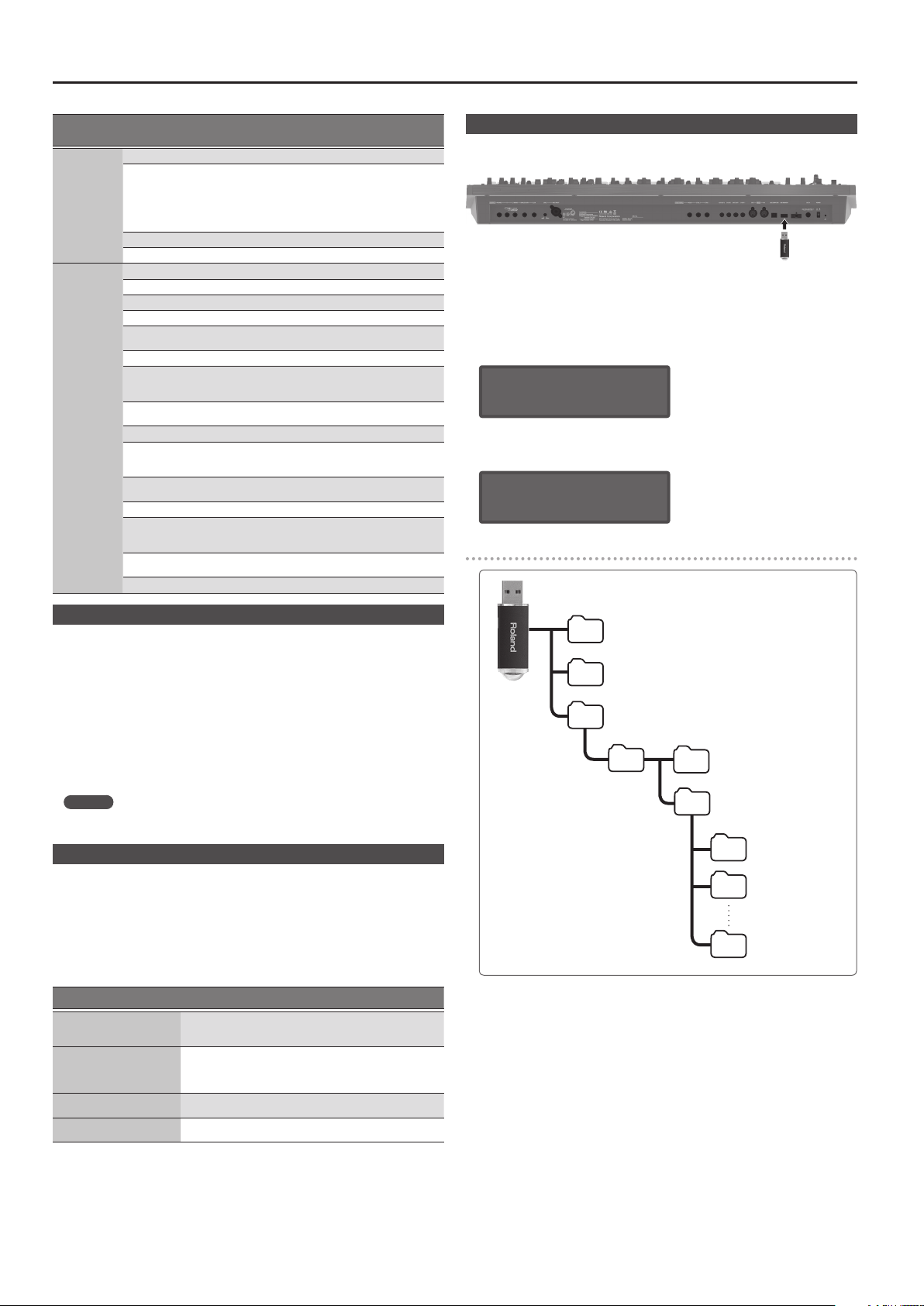
Overall Settings for the JD-XA
Menu
[Shift]+
Cursor [K] [J]
MIC REVERB
MASTER EQ
Parameter
Cursor [K] [J]
Switch OFF, ON Switches the reverb on/o.
Type
Time 0–127 Time length of reverberation
Level 0–127 Volume of the reverb sound
Switch OFF, ON Switches the master EQ on/o.
Input Gain -15 dB–+15 dB Adjusts the input gain of the master EQ.
Low Freq 16 Hz–800 Hz Frequency of the low range.
Low Gain -15 dB–+15 dB Gain of the low frequency range.
Mid1 Freq
Mid1 Gain -15 dB–+15 dB Gain of the middle frequency range 1.
Mid1 Q 0.5–8.0
Mid2 Freq
Mid2 Gain -15 dB–+15 dB Gain of the middle frequency range 2.
Mid2 Q 0.5–8.0
Mid3 Freq
Mid3 Gain -15 dB–+15 dB Gain of the middle frequency range 3.
Mid3 Q 0.5–8.0
HighFreq
High Gain -15 dB–+15 dB Gain of the high frequenc y range.
Value
[-] [+]
ROOM1,
ROOM2,
STAGE1,
STAGE2, HALL1,
HALL2, DELAY,
PAN-DLY
16 Hz–16000
Hz
16 Hz–16000
Hz
16 Hz–16000
Hz
630 Hz–16000
Hz
Explanation
Type of reverb
Frequency of the middle range 1.
Width of the middle frequency range 1.
Set a higher value for Q to narrow the range
to be aected.
Frequency of the middle range 2.
Width of the middle frequency range 2.
Set a higher value for Q to narrow the range
to be aected.
Frequency of the middle range 3.
Width of the middle frequency range 3.
Set a higher value for Q to narrow the range
to be aected.
Frequency of the high range.
Formatting a USB Flash Drive (USB MEM FORMAT)
* Never turn o the power or remove the USB ash drives while the screen indicates “Executing.”
* Carefully insert the USB ash drives all the way in—until it is rmly in place.
Press the [Menu] button.
1.
Use the Cursor [K] [J] buttons to select “UTILITY,” and then press the [Enter]
2.
button.
Use the Cursor [K] [J] buttons to select “USB MEM FORMAT,” and then press
3.
the [Enter] button.
A conrmation message appears.
Format USB Mem?
[Exit]:N [Ent]:Y
If you decide to cancel, press the [Exit] button.
Press the [Enter] button to execute.
4.
When formatting is complete, the following screen appears.
Completed!
The folder structure of a USB ash drive
Saving the System Settings
System settings revert to their previous state when you turn o the power. If you
want to keep these settings even after the power is turned o, you must save the
system settings.
Press the [Write] button.
1.
Use the Cursor [K] [J] buttons to select “SYSTEM,” and then press the [Enter]
2.
button.
A conrmation message appears.
If you decide to cancel, press the [Exit] button.
Press the [Enter] button.
3.
A screen indicating “Completed!” appears, and the data is saved.
* NEVER turn the power o while you are saving settings.
MEMO
You can also save the system settings by pressing the [Write] button in the system
setting screen.
Convenient Functions (UTILITY)
These functions let you back up the JD-XA’s internal data to a USB ash drive, or to
restore data from a USB ash drive into the JD-XA.
Other utility functions let you return the JD-XA to its factory-set state, or initialize a
USB ash drive.
Press the [Menu] button.
1.
Use the Cursor [K] [J] buttons to select “UTILITY,” and then press the [Enter]
2.
button.
The UTILITY screen appears.
Menu items
Cursor [K] [J]
BACKUP
RESTORE
FACTORY RESET
USB MEM FORMAT
Use the Cursor [K] [J] buttons to select the item that you want to edit, and
3.
press the [Enter] button.
Explanation
Backs up data to a le with the name you specify.
System and user setting (. SVD) and pattern (. BIN) les are created.
“Backing Up Data (BACKUP)” (p. 15)
&
Restores data from the le you specify.
Data is restored from the system and user setting (. SVD) and
pattern (. BIN) les.
“Restoring Data (RESTORE)” (p. 15)
&
“Returning to the Factory Settings (FACTORY RESET)”
&
(p. 15)
“Formatting a USB Flash Drive (USB MEM FORMAT)”
&
(p. 14)
EXPORT SMF folder
Exported SMF les are saved here.
IMPORT folder
Files that you want to import to the JD-XA should be copied here.
(File name) . SVD : Tone import
(File name) . MID : SMF import
ROLAND folder
JD-XA programs and backup data are saved here.
BACKUP folder
Backup data is saved here.
JD-XA folder
PROGRAM folder
Programs in the USB ash drive are
saved here.
A folder
Bank A program data
B folder
Bank B program data
P folder
Bank P program data
14
Page 15

Overall Settings for the JD-XA
Restoring Backup Data from a USB Flash Drive
Use a USB ash drive sold by Roland. We cannot guarantee operation if any other
product is used.
Backing Up Data (BACKUP)
Press the [Menu] button.
1.
Use the Cursor [K] [J] buttons to select “UTILITY,” and then press the [Enter]
2.
button.
UTILITY [Ent]
BACKUP
Use the Cursor [K] [J] buttons to select “BACKUP,” and then press the [Enter]
3.
button.
The name input screen appears.
BACKUP NAME[Ent]
JDXA_BKUP .SVD
Use the cursor [K] [J] buttons to move the cursor, and use the [-] [+] buttons
4.
to select characters.
When you’ve specied the name, press the [Enter] button.
5.
A conrmation message appears.
Backup?
[Exit]:N [Ent]:Y
If you decide to cancel, press the [Exit] button.
Press the [Enter] button.
6.
Restoring Data (RESTORE)
NOTE
When you execute the restore operation, all user data is rewritten.
If the JD-XA contains important data, back it up on a USB ash drive using a
dierent name before you execute the restore operation.
Press the [Menu] button.
1.
Use the Cursor [K] [J] buttons to select “UTILITY,” and then press the [Enter]
2.
button.
Use the Cursor [K] [J] buttons to select “RESTORE,” and then press the [Enter]
3.
button.
Use the [-] [+] buttons to select the le that you want to restore, and then
4.
press the [Enter] button.
A conrmation message appears.
Items initialized by Factory Reset
5All user programs (including arpeggios, patterns, and eects)
5System settings
5LED CUSTOMIZE settings
Making the Power Automatically Turn O After a Time
(Auto O)
Press the [Menu] button.
1.
Use the Cursor [K] [J] buttons to select “SYSTEM,” and then press the [Enter]
2.
button.
GENERAL:
Auto Off 30min
Hold down the [Shift] button and use the cursor [K] [J] buttons to select
3.
“GENERAL.”
Use the Cursor [K] [J] buttons to select “Auto O” and use the [-] [+] buttons
4.
to change the setting.
If you don’t want the unit to turn o automatically, choose “OFF” setting.
Press the [Exit] button several times to return to the program select screen.
5.
Customizing the Knob and Slider Illumination (LED CUSTOMIZE)
By using the LED Customize settings you can control the way in which the LEDs
illuminate regardless of the Part Select status.
Press the [Menu] button.
1.
Use the Cursor [K] [J] buttons to select “LED CUSTOMIZE,” and then press
2.
the [Enter] button.
Use the [-] [+] buttons to specify the LED Customize parameter.
3.
Move the knobs and sliders to specify how you want the LEDs to illuminate.
4.
Press the [Write] button to save the settings.
5.
MEMO
The LED illumination status changes (all lit , all unlit) each time you hold
down the [Shift] button and press the [Program Select] (Init) button in the LED
CUSTOMIZE screen.
Restore?
[Exit]:N [Ent]:Y
If you decide to cancel, press the [Exit] button.
Press the [Enter] button.
5.
When restoring is complete, the following screen appears.
Completed.
Turn off power.
Turn the power of the JD-XA o, then on again.
6.
Returning to the Factory Settings (FACTORY RESET)
Press the [Menu] button.
1.
Use the Cursor [K] [J] buttons to select “UTILITY,” and then press the [Enter]
2.
button.
Use the Cursor [K] [J] buttons to select “FACTORY RESET,” and then press
3.
the [Enter] button.
A conrmation message appears.
Factory Reset?
[Exit]:N [Ent]:Y
If you decide to cancel, press the [Exit] button.
Press the [Enter] button to execute.
4.
Turn the power of the JD-XA o, then on again.
5.
15
Page 16

List of Shortcut Keys
* “[A]+[B]” indicates the operation of “holding down the [A] button and pressing the [B] button.”
Shortcut Explanation
Part
[Shift]+ Part On [01]–[04] Turns part mute on/o (p. 4).
[Arpeggio]+ Part On [01]–[04] Turns each part’s Arpeggio Sw on/o (p. 9).
[Vocoder]+ Part On [01]–[04] Turns each part’s Vocoder Send Sw on/o.
Press Part On [01]–[04] + keyboard
twice (to specify the lower and
upper limit)
Controllers
[Shift]+[Modulation] lever
[Shift] + operate Wheel 1 Displays the Wheel 1 assignment (p. 12).
[Shift] + operate Wheel 2 Displays the Wheel 2 assignment (p. 12).
[Shift]+ operate Pedal 1 Displays the Pedal 1 assignment (p. 12).
[Shift]+ operate Pedal 2 Displays the Pedal 2 assignment (p. 12).
Common section
[Exit] + controller Displays the parameter (the value does not change).
[-], [+]
[Shift]+[-] [+] Makes the value change more greatly.
[Shift]+[K] [J] Moves to the previous/next parameter section.
[Shift]+[MIDI CTRL] Turns trigger mode on/o (p. 11).
[Shift]+[Menu]
[Shift]+[Write] Displays the LED Customize screen (p. 15).
[Shift]+[Enter] Executes the Manual function (p. 2).
[Shift]+[Program Select]
[Shift]+[Bank] Displays the Copy screen (p. 7).
[Shift]+[Favorite] Displays the Favorite Util screen (p. 7).
[Program Select]+[01]–[16] Selects a program
[Bank]+[01]–[16]
[Favorite]+[01]–[16]
LFO
[Shift]+ [Tempo Sync]
[Shift]+ [AMP Depth]
OSC1
[Shift]+[Pitch]
Part Select [01]–[04]+[Pitch] Adjust the pan of each part.
[Shift]+[PW]
PITCH ENV
[Shift]+[Depth]
FILTER
[Shift]+[Cuto]
[Shift]+[Key Follow]
[Shift]+[Env Depth]
AMP
[Shift]+[Level]
Part Sel [01]–[04]+[AMP Level] Adjust the volume of each part.
EFFECTS
[Shift]+[TFX 1 On]
[Shift]+[TFX 2 On]
[Shift]+[Part MFX On]
Species the key range of each part.
Enters the Modulation LFO setting state.
To exit this state, use [Shift] + [Modulation] lever once
again.
Hold down one button while pressing the other button to
make the value change rapidly.
Display Lock on/o.
If this is on, the corresponding parameter is not displayed
when you move a controller (the value is changed).
Displays the Init screen (p. 7).
(In the Arpeggio Edit screen, initializes the arpeggio
pattern.)
Normally: Switches the program bank (p. 4).
Favorites: Switches the favorite bank (p. 7).
Registers the current program number as a favorite
(p. 7).
Analog part: Turns LFO Key Trigger on/o.
Digital part: Turns LFO Key Trigger on/o.
Analog part: No function.
Digital part: Adjusts LFO Pan Depth.
Analog part: No function.
Digital part: Adjusts AMP Pan.
Analog part: No function.
Digital part: Adjusts OSC PW Shift (Pulse Width Shift).
Analog part: Adjusts Pitch Env Velo Sens (Velocity Sens).
Digital part: No function.
Analog part: Adjusts FILTER Cuto Fine.
Digital part: No function.
Analog part: Adjusts FILTER KF Fine (Key Follow Fine).
Digital part: No function.
Analog part: Adjusts FILTER Velo Sens (Velocity Sens).
Digital part: Adjusts FILTER Velo Sens (Velocity Sens).
Analog part: Adjusts AMP Velo Sens ( Velocity Sens).
Digital part: Adjusts AMP Velo Sens (Velocity Sens).
Displays the TFX 1 screen (TFX1 Sw setting does not
change).
Displays the TFX 2 screen (TFX2 Sw setting does not
change).
Displays the Part MFX screen (Part MFX Sw setting does not
change).
Shortcut Explanation
PATTERN SEQ
[Shift]+[01]–[16]
[Pattern Length]+[01]–[16]
[01]–[16] + knob
(during Step REC2)
Keyboard + [01]–[16]
(during Step REC2)
[Shift]+[Erase] Displays the Pattern Erase menu (p. 9).
[Erase]+Part On [01]–[04]
[Erase]+[01]–[16]
[Erase] + knob
[Shift]+[Step REC]
[Shift]+[Realtime REC]
[Shift]+[Tap] Displays the tempo parameter.
At the left side of the keyboard
[Shift]+OCTAVE [Up] [Down] Sets Tone Common Oct Shift (Octave Shift).
[Shift]+[Key Hold]
[Shift]+[Arpeggio]
For details on the parameters, refer to “Parameter Guide (English)” (PDF).
&
Use the [01]–[16] buttons to move the region (measures) of
performance data that is displayed (p. 8).
Records the knob operation at the specied step (position)
(p. 8).
Records the keyboard note at the specied step (position).
Displays the Pattern Erase menu and assigns the specied
part as the target for erasure (p. 9).
Erases the all recorded data included in the specied step
of the applicable Step REC part (p. 8).
During Realtime Erase: Assigns the knob data as the target
for erasure (p. 8).
Displays the Step REC setting screen (p. 8).
(The Step REC status does not change)
Displays the Realtime REC setting screen (p. 8).
(The Realtime REC status does not change)
Switches the Kbd Velocity setting (Real , xed value
(default:127)) (p. 12).
Displays the arpeggio screen (p. 9).
(The arpeggio switch does not change)
16
Page 17

Error Messages
If an incorrect operation is performed, or if processing could not be performed as you specied, an error message appears.
Refer to the explanation for the error message that appears, and take the appropriate action.
Message Meaning Action
Incorrect File!
USBMem NotReady!
Read Error!
Write Error!
USB Memory Full!
INT Memory Full!
Sys Mem Damaged!
MIDI Bu Full!
MIDI Oine! The MIDI IN connection was broken.
Not Registered! No favorites have been registered.
No More Regist!
Program Error!
Now Playing!
The SMF being imported cannot be
loaded into the JD-XA.
The USB ash drive is not inserted,
or is inserted incompletely.
The USB ash drive was removed
after you selected data that was on
the USB ash drive.
The format of the USB ash drive is
invalid.
Data could not be read from the
USB ash drive.
The le is damaged. Do not use this le.
Data could not be written to the
USB ash drive.
The format of the USB ash drive is
invalid.
There is insucient space on the
USB ash drive.
There is insucient space on the
internal memory.
The contents of the JD-XA’s save
area may be damaged.
An unusually large amount of MIDI
data was received, and could not be
processed.
No more favorites have been
registered.
The JD-XA was unable to start up.
The program could not be read
correctly. Alternatively, the system
update program may be invalid.
Since the JD-XA is playing, this
operation cannot be executed.
SMF data containing time signature
data other than 4/4 cannot be
loaded into the JD-XA. Correct the
time signature data of the SMF.
Set the SMF being imported to
Format 0.
Turn o the unit, rmly insert the
USB ash drive, and then turn on
the unit once again (p. 4).
Use the JD-XA to format the USB
ash drive (p. 14).
Make sure that the USB ash drive is
correctly connected.
Also make sure that you’re using a
USB ash drive sold by Roland.
Make sure that the USB ash drive is
correctly connected.
Also make sure that you’re using a
USB ash drive sold by Roland.
Use the JD-XA to format the USB
ash drive (p. 14).
Delete unneeded data.
Either initialize a pattern of an
unneeded program and resave it, or
save it to a USB ash drive.
Execute the factory reset operation
(p. 15).
If this does not solve the problem,
contact your dealer or customer
support.
Reduce the amount of MIDI
messages that are being
transmitted.
Check that there is no problem with
the MIDI cable connected to the
JD-XA’s MIDI IN, and that the MIDI
cable was not disconnected.
Check whether any favorites are
registered (p. 7).
Check the currently selected favorite
number and the direction (“FAV-UP”
or “FAV-DOWN”) that’s assigned to
the pedal (p. 12).
Use the correct program to perform
the update once again.
If this does not solve the problem,
contact your dealer or customer
support.
Stop playback before you execute
the operation.
Message Meaning Action
Now Recording!
Rec Overow!
Pattern Full!
Not Found!
Since the JD-XA is recording, this
operation cannot be executed.
Since a large amount of recorded
data was input all at once, it could
not be processed correctly.
The maximum number of notes that
can be recorded in one pattern has
been exceeded; the pattern cannot
be recorded any further.
The le was not found on the USB
ash drive.
Stop recording before you execute
the operation.
Reduce the amount of recorded
data.
Delete unneeded data from the
pattern that you’re recording.
Make sure that the le exists on the
USB ash drive.
Main Specications
Roland JD-XA: Synthesizer keyboard
Keyboard 49 keys (with velocity and channel aftertouch)
Power Supply AC adaptor
Current draw 3,000 mA
Dimensions
Weight
Accessories
Options
* In the interest of product improvement, the specications and/or appearance of this unit are
subject to change without prior notice.
899 (W) x 388 (D) x 111 (H) mm
35-7/16 (W) x 15-5/16 (D) x 4-3/8 (H) inches
6.5 kg (excluding AC adaptor)
14 lbs 6 oz
Owner’s manual
AC adaptor
Power cord
Keyboard stand (*1): KS-18Z
Pedal Switch: DP series
Expression Pedal: EV-5
USB Flash Memory (*2)
*1 When using the KS-18Z ensure that the height of the unit is one meter or
lower.
*2 Use USB Flash Memory (supports USB 2.0 Hi-Speed Flash Memory) sold by
Roland. We cannot guarantee operation if other products are used.
17
Page 18

USING THE UNIT SAFELY
WARNING
To completely turn o power to the unit,
pull out the plug from the outlet
Even with the power switch turned o, this unit is
not completely separated from its main source of
power. When the power needs to be completely
turned o, turn o the power switch on the unit,
then pull out the plug from the outlet. For this
reason, the outlet into which you choose to connect the power
cord’s plug should be one that is within easy reach and readily
accessible.
Concerning the Auto O function
The power to this unit will be turned o
automatically after a predetermined amount of
time has passed since it was last used for playing
music, or its buttons or controls were operated
(Auto O function). If you do not want the power
to be turned o automatically, disengage the Auto O function
(p. 15).
Use only the stand that is recommended
This unit should be used only with a stand that is
recommended by Roland.
Do not place in a location that is unstable
When using the unit with a stand recommended
by Roland, the stand must be carefully placed so
it is level and sure to remain stable. If not using a
stand, you still need to make sure that any location
you choose for placing the unit provides a level
surface that will properly support the unit, and keep it from
wobbling.
WARNING
Precautions regarding placement of this
unit on a stand
Be sure to follow the instructions in the Owner’s
Manual carefully when placing this unit on a stand
(p. 18).
If it is not set up properly, you risk creating an
unstable situation which could lead to the unit
falling or the stand toppling, and may result in injury.
Use only the supplied AC adaptor and the
correct voltage
Be sure to use only the AC adaptor supplied with
the unit. Also, make sure the line voltage at the
installation matches the input voltage specied on
the AC adaptor’s body. Other AC adaptors may use
a dierent polarity, or be designed for a dierent
voltage, so their use could result in damage, malfunction, or
electric shock.
Use only the supplied power cord
Use only the attached power cord. Also, the
supplied power cord must not be used with any
other device.
CAUTION
Use only the specied stand(s)
This unit is designed to be used in combination
with specic stands (KS-18Z) manufactured by
Roland. If used in combination with other stands,
you risk sustaining injuries as the result of this
product dropping down or toppling over due to a
lack of stability.
Evaluate safety issues before using stands
Even if you observe the cautions given in the
owner’s manual, certain types of handling may
allow this product to fall from the stand, or cause
the stand to overturn. Please be mindful of any
safety issues before using this product.
Handle the ground terminal carefully
If you remove the screw from the ground terminal,
be sure to replace it; don’t leave it lying around
where it could accidently be swallowed by small
children. When refastening the screw, make that it
is rmly fastened, so it won’t come loose.
Precautions concerning use of phantom
power supply
Always turn the phantom power o when
connecting any device other than condenser
microphones that require phantom power. You
risk causing damage if you mistakenly supply
phantom power to dynamic microphones, audio
playback devices, or other devices that don’t require such
power. Be sure to check the specications of any microphone
you intend to use by referring to the manual that came with it.
(This instrument’s phantom power: 48 V DC, 10 mA Max)
IMPORTANT NOTES
Placement
5Do not allow objects to remain on top of the keyboard. This
can be the cause of malfunction, such as keys ceasing to
produce sound.
5Depending on the material and temperature of the surface
on which you place the unit, its rubber feet may discolor or
mar the surface.
Repairs and Data
5Before sending the unit away for repairs, be sure to make
a backup of the data stored within it; or you may prefer to
write down the needed information. Although we will do our
utmost to preserve the data stored in your unit when we carry
out repairs, in some cases, such as when the memory section
is physically damaged, restoration of the stored content may
be impossible. Roland assumes no liability concerning the
restoration of any stored content that has been lost.
Additional Precautions
5Any data stored within the unit can be lost as the result
of equipment failure, incorrect operation, etc. To protect
yourself against the irretrievable loss of data, try to make a
habit of creating regular backups of the data you’ve stored in
the unit.
5Roland assumes no liability concerning the restoration of any
stored content that has been lost.
5Never strike or apply strong pressure to the display.
5Use only the specied expression pedal (EV-5; sold
separately). By connecting any other expression pedals, you
risk causing malfunction and/or damage to the unit.
5Do not use connection cables that contain a built-in resistor.
Using External Memories
5Please observe the following precautions when handling
external memory devices. Also, make sure to carefully
observe all the precautions that were supplied with the
external memory device.
5Do not remove the device while reading/writing is in
progress.
5To prevent damage from static electricity, discharge all
static electricity from your person before handling the
device.
Intellectual Property Right
5It is forbidden by law to make an audio recording, video
recording, copy or revision of a third party’s copyrighted work
(musical work, video work, broadcast, live performance, or
other work), whether in whole or in part, and distribute, sell,
lease, perform, or broadcast it without the permission of the
copyright owner.
5Do not use this product for purposes that could infringe on a
copyright held by a third party. We assume no responsibility
whatsoever with regard to any infringements of third-party
copyrights arising through your use of this product.
5The copyright of content in this product (the sound waveform
data, style data, accompaniment patterns, phrase data, audio
loops and image data) is reserved by Roland Corporation.
5Purchasers of this product are permitted to utilize said
content (except song data such as Demo Songs) for the
creating, performing, recording and distributing original
musical works.
5Purchasers of this product are NOT permitted to extract
said content in original or modied form, for the purpose
of distributing recorded medium of said content or making
them available on a computer network.
Placing the JD-XA on a Stand
If you want to place the JD-XA on a stand, use the Roland KS-18Z.
Be careful not to pinch your ngers when setting up the stand.
Place the instrument on the stand as follows.
KS-18Z
Place the
JD-XA so that it
is in the center
of the stand
Adjust so that
the height does
not exceed 1
meter (Adjust
the stand to a
level no higher
than the third
level from the
bottom)
Place the
JD-XA so that it
is in the center
of the stand
5MMP (Moore Microprocessor Portfolio) refers to a patent
portfolio concerned with microprocessor architecture, which
was developed by Technology Properties Limited (TPL).
Roland has licensed this technology from the TPL Group.
5ASIO is a trademark and software of Steinberg Media
Technologies GmbH.
5This product contains eCROS integrated software platform of
eSOL Co.,Ltd. eCROS is a trademark of eSOL Co., Ltd. in Japan.
5Roland, SuperNATURAL are either registered trademarks or
trademarks of Roland Corporation in the United States and/
or other countries.
5Company names and product names appearing in this
document are registered trademarks or trademarks of their
respective owners.
Adjust the outer width of the stand
within the range shown below
800 mm–between the rubber feet of
the JD-XA
Between the rubber feet
800 mm or
more
Top view
Page 19

For the U.K.
IMPORTANT: THE WIRES IN THIS MAINS LEAD ARE COLOURED IN ACCORDANCE WITH THE FOLLOWING CODE.
BLUE:
BROWN:
As the colours of the wires in the mains lead of this apparatus may not correspond with the coloured markings identifying
the terminals in your plug, proceed as follows:
The wire which is coloured BLUE must be connected to the terminal which is marked with the letter N or coloured BLACK.
The wire which is coloured BROWN must be connected to the terminal which is marked with the letter L or coloured RED.
Under no circumstances must either of the above wires be connected to the earth terminal of a three pin plug.
NEUTRAL
LIVE
For the USA
FEDERAL COMMUNICATIONS COMMISSION
RADIO FREQUENCY INTERFERENCE STATEMENT
This equipment has been tested and found to comply with the limits for a Class B digital device, pursuant to Part 15 of the FCC Rules.
These limits are designed to provide reasonable protection against harmful interference in a residential installation. This equipment
generates, uses, and can radiate radio frequency energy and, if not installed and used in accordance with the instructions, may cause
harmful interference to radio communications. However, there is no guarantee that interference will not occur in a particular
installation. If this equipment does cause harmful interference to radio or television reception, which can be determined by turning
the equipment o and on, the user is encouraged to try to correct the interference by one or more of the following measures:
– Reorient or relocate the receiving antenna.
– Increase the separation between the equipment and receiver.
– Connect the equipment into an outlet on a circuit dierent from that to which the receiver is connected.
– Consult the dealer or an experienced radio/TV technician for help.
This device complies with Part 15 of the FCC Rules. Operation is subject to the following two conditions:
(1) this device may not cause harmful interference, and
(2) this device must accept any interference received, including interference that may cause undesired operation.
This equipment requires shielded interface cables in order to meet FCC class B limit.
Any unauthorized changes or modications not expressly approved by the party responsible for compliance could void the user’s
authority to operate the equipment.
CAN ICES-3 (B)/NMB-3 (B)
Manufacturer:
2036-1 Nakagawa, Hosoe-cho, Kita-ku, Hamamatsu, Shizuoka 431-1304, JAPAN
ENA 23 Zone 1 nr. 1620 Klaus-Michael Kuehnelaan 13, 2440 Geel, BELGIUMImporter:
For Canada
For Korea
Page 20

For EU Countries
UK
DE
FR
IT
ES
PT
NL
DK
NO
SE
FI
HU
PL
CZ
SK
EE
LT
LV
SI
GR
Page 21

For the USA
DECLARATION OF CONFORMITY
Compliance Information Statement
Model Name :
Type of Equipment :
Responsible Party :
Address :
Telephone :
产品中有害物质的名称及含量
JD-XA
SYNTHESIZER KEYBOARD
Roland Corporation U.S.
5100 S. Eastern Avenue Los Angeles, CA 90040-2938
(323) 890-3700
有害物质
×
×
×
×
本表格依据SJ/T 11364的规定编制。
表示该有害物质在该部件所有均质材料中的含量均在GB/T 26572 规定的限量要求以下。
О:
×:
表示该有害物质至少在该部件的某一均质材料中的含量超出GB/T 26572的限量要求。
(企业可在此处,根据实际情况对上表中打“×”的技术原因进行进一步说明。)
お問い合わせの窓口
製品に関するお問い合わせ先
ローランドお客様相談センター
電話受付時間: 月曜日~金曜日 10:00~17:00(弊社規定の休日を除く)
※IP電話からおかけになって繋がらない場合には、お手数ですが、電話番号の前に“0000”
(ゼロ4回)をつけてNTTの一般回線からおかけいただくか、携帯電話をご利用ください。
※上記窓口の名称、電話番号等は、予告なく変更することがありますのでご了承ください。
最新サポート情報
製品情報、イベント/キャンペーン情報、サポートに関する情報など
ローランド・ホームページ
ボス・ホームページ
050-3101-2555
https://www.roland.com/jp/
https://www.boss.info/jp/
'16. 10. 01 現在(Roland)
Page 22

* 5 1 0 0 0 4 5 4 9 1 - 0 2 *
When you need repair service, access this URL and nd your nearest Roland Service Center or authorized Roland distributor in
Roland Service Centers and Distributors
your country.
http://roland.cm/service
Roland Service Centers and Distributors
 Loading...