

Page 1
Owner’s Manual (this document)
Read this rst. It explains the basic things you need to know in order to use
the INTEGRA-7.
PDF Manual (download from the Web)
• Parameter Guide
This explains all parameters of the INTEGRA-7.
• Sound List
This is a list of the sounds built into the INTEGRA-7.
• MIDI Implementation
This is detailed information about MIDI messages.
To obtain the PDF manual
Enter the following URL in your computer.
1.
http://www.roland.com/manuals/
2. Choose “INTEGRA-7” as the product name.
Page 2
WARNING: To reduce the risk of fire or electric shock, do not expose this apparatus to rain or moisture.
CAUTION
RISK OF ELECTRIC SHOCK
DO NOT OPEN
ATTENTION: RISQUE DE CHOC ELECTRIQUE NE PAS OUVRIR
CAUTION: TO REDUCE THE RISK OF ELECTRIC SHOCK,
DO NOT REMOVE COVER (OR BACK).
NO USER-SERVICEABLE PARTS INSIDE.
REFER SERVICING TO QUALIFIED SERVICE PERSONNEL.
The lightning flash with arrowhead symbol, within an
equilateral triangle, is intended to alert the user to the
presence of uninsulated “dangerous voltage” within the
product’s enclosure that may be of sufficient magnitude to
constitute a risk of electric shock to persons.
The exclamation point within an equilateral triangle is
intended to alert the user to the presence of important
operating and maintenance (servicing) instructions in the
literature accompanying the product.
INSTRUCTIONS PERTAINING TO A RISK OF FIRE, ELECTRIC SHOCK, OR INJURY TO PERSONS.
IMPORTANT SAFETY INSTRUCTIONS
SAVE THESE INSTRUCTIONS
WARNING - When using electric products, basic precautions should always be followed, including the following:
1. Read these instructions.
2. Keep these instructions.
3. Heed all warnings.
4. Follow all instructions.
5. Do not use this apparatus near water.
6. Clean only with a dry cloth.
7. Do not block any of the ventilation openings. Install in
accordance with the manufacturers instructions.
8. Do not install near any heat sources such as radiators,
heat registers, stoves, or other apparatus (including
amplifiers) that produce heat.
9. Do not defeat the safety purpose of the polarized or
grounding-type plug. A polarized plug has two blades with
one wider than the other. A grounding type plug has two
blades and a third grounding prong. The wide blade or the
third prong are provided for your safety. If the provided plug
does not fit into your outlet, consult an electrician for
replacement of the obsolete outlet.
10. Protect the power cord from being walked on or pinched
particularly at plugs, convenience receptacles, and the
point where they exit from the apparatus.
11. Only use attachments/accessories specified by the
manufacturer.
12. Use only with the cart, stand, tripod, bracket,
or table specified by the manufacturer, or
sold with the apparatus. When a cart is used,
use caution when moving the cart/apparatus
combination to avoid injury from tip-over.
13. Unplug this apparatus during lightning storms or when
unused for long periods of time.
14. Refer all servicing to qualified service personnel. Servicing
is required when the apparatus has been damaged in any
way, such as power-supply cord or plug is damaged, liquid
has been spilled or objects have fallen into the apparatus,
the apparatus has been exposed to rain or moisture, does
not operate normally, or has been dropped.
For the U.K.
WARNING:
IMPORTANT:
As the colours of the wires in the mains lead of this apparatus may not correspond with the coloured markings identifying
the terminals in your plug, proceed as follows:
The wire which is coloured GREEN-AND-YELLOW must be connected to the terminal in the plug which is marked by the
letter E or by the safety earth symbol or coloured GREEN or GREEN-AND-YELLOW.
The wire which is coloured BLUE must be connected to the terminal which is marked with the letter N or coloured BLACK.
The wire which is coloured BROWN must be connected to the terminal which is marked with the letter L or coloured RED.
THIS APPARATUS MUST BE EARTHED
THE WIRES IN THIS MAINS LEAD ARE COLOURED IN ACCORDANCE WITH THE FOLLOWING CODE.
GREEN-AND-YELLOW: EARTH, BLUE: NEUTRAL, BROWN: LIVE
Page 3
USING THE UNIT SAFELY
Before using this unit, carefully read the sections entitled: “IMPORTANT SAFETY INSTRUCTIONS” (p. 2), “USING THE UNIT SAFELY” (p. 3), and
“IMPORTANT NOTES” (p. 5). These sections provide important information concerning the proper operation of the unit. Additionally, in order to
feel assured that you have gained a good grasp of every feature provided by your new unit, Owner’s manual should be read in its entirety. The
manual should be saved and kept on hand as a convenient reference.
Copyright © 2012 ROLAND CORPORATION
All rights reserved. No part of this publication may be reproduced in any form without the written permission of ROLAND CORPORATION.
Quick Guide
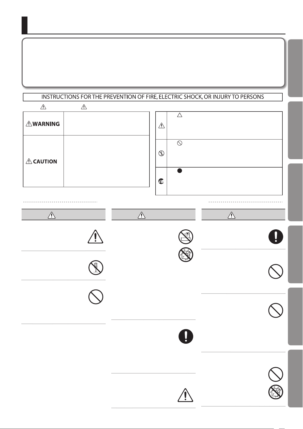
About WARNING and CAUTION Notices
Used for instructions intended to alert the
user to the risk of death or severe injury
should the unit be used improperly.
Used for instructions intended to alert the
user to the risk of injury or material
damage should the unit be used
improperly.
* Material damage refers to damage or
other adverse effects caused with
respect to the home and all its
furnishings, as well to domestic animals
or pets.
ALWAYS OBSERVE THE FOLLOWING
WARNING
Make sure that the power cord is grounded
Connect mains plug of this model
to a mains socket outlet with a
protective earthing connection.
Do not disassemble or modify by yourself
Do not open or perform any internal
modications on the unit.
Do not repair or replace parts by yourself
Do not attempt to repair the unit,
or replace parts within it (except
when this manual provides specic
instructions directing you to do so).
Refer all servicing to your retailer, the nearest
Roland Service Center, or an authorized Roland
distributor, as listed on the “Information” page.
Do not use or store in the following types of locations
• Subject to temperature extremes
(e.g., direct sunlight in an enclosed
vehicle, near a heating duct, on top
of heat-generating equipment);
or are
• Damp (e.g., baths, washrooms, on
wet oors); or are
• Exposed to steam or smoke; or are
• Subject to salt exposure; or are
• Humid; or are
• Exposed to rain; or are
• Dusty or sandy; or are
• Subject to high levels of vibration and
shakiness.
Do not place in an unstable location
When using the unit with a rack or
stand recommended by Roland,
the rack or stand must be carefully
placed so it is level and sure to
remain stable. If not using a rack or stand, you
still need to make sure that any location you
choose for placing the unit provides a level
surface that will properly support the unit, and
keep it from wobbling.
Connect the power cord to an outlet of the correct
voltage
The unit should be connected to
a power supply only of the type
described as marked on the rear
side of unit.
About the Symbols
The symbol alerts the user to important instructions or
warnings.The specific meaning of the symbol is
determined by the design contained within the triangle. In
the case of the symbol at left, it is used for general
cautions, warnings, or alerts to danger.
The symbol alerts the user to items that must never be
carried out (are forbidden). The specific thing that must
not be done is indicated by the design contained within
the circle. In the case of the symbol at left, it means that
the unit must never be disassembled.
The symbol alerts the user to things that must be
carried out. The specific thing that must be done is
indicated by the design contained within the circle. In the
case of the symbol at left, it means that the power-cord
plug must be unplugged from the outlet.
WARNING
Introduction Playing/Creating Sounds Use with a Computer Overall Settings Appendix
WARNING
Use only the included power cord
Use only the attached power-supply
cord. Also, the included power cord
must not be used with any other
device.
Do not bend the power cord or place heavy objects on
it
Do not excessively twist or bend the
power cord, nor place heavy objects
on it. Doing so can damage the cord,
producing severed elements and
short circuits. Damaged cords are re and shock
hazards!
Avoid extended use at high volume
This unit, either alone or in
combination with an amplier and
headphones or speakers, may be
capable of producing sound levels
that could cause permanent hearing loss. Do
not operate for a long period of time at a high
volume level, or at a level that is uncomfortable.
If you experience any hearing loss or ringing in
the ears, you should immediately stop using the
unit, and consult an audiologist.
Don’t allow foreign objects or liquids to enter unit;
never place containers with liquid on unit
Do not place containers containing
liquid on this product. Never allow
foreign objects (e.g., ammable
objects, coins, wires) or liquids
(e.g., water or juice) to enter this
product. Doing so may cause short
circuits, faulty operation, or other
malfunctions.
3
Page 4
USING THE UNIT SAFELY
WARNING
Turn o the unit if an abnormality or malfunction
occurs
Immediately turn the unit o,
remove the power cord from the
outlet, and request servicing by
your retailer, the nearest Roland
Service Center, or an authorized Roland
distributor, as listed on the “Information” page
when:
• The power-supply cord or the plug has been
damaged; or
• If smoke or unusual odor occurs; or
• Objects have fallen into, or liquid has been
spilled onto the unit; or
• The unit has been exposed to rain (or
otherwise has become wet); or
• The unit does not appear to operate normally
or exhibits a marked change in performance.
Adults must provide supervision in places where
children are present
When using the unit in locations
where children are present, be
careful so no mishandling of the
unit can take place. An adult should
always be on hand to provide supervision and
guidance.
Do not drop or subject to strong impact
Protect the unit from strong impact.
(Do not drop it!)
Do not share an outlet with an unreasonable number
of other devices
Do not force the unit’s powersupply cord to share an outlet with
an unreasonable number of other
devices. Be especially careful when
using extension cords—the total power used by
all devices you have connected to the extension
cord’s outlet must never exceed the power
rating (watts/amperes) for the extension cord.
Excessive loads can cause the insulation on the
cord to heat up and eventually melt through.
WARNING
Do not use overseas
Before using the unit in a foreign
country, consult with your retailer,
the nearest Roland Service Center,
or an authorized Roland distributor,
as listed on the “Information” page.
CAUTION
Place in a well ventilated location
The unit should be located so that
its location or position does not
interfere with its proper ventilation.
Grasp the plug when connecting or disconnecting the
power cord
Always grasp only the plug on the
power-supply cord when plugging
into, or unplugging from, an outlet
or this unit.
Periodically clean the power cord’s plug
At regular intervals, you should
unplug the power plug and clean it
by using a dry cloth to wipe all dust
and other accumulations away from
its prongs. Also, disconnect the power plug
from the power outlet whenever the unit is to
remain unused for an extended period of time.
Any accumulation of dust between the power
plug and the power outlet can result in poor
insulation and lead to re.
Manage cables for safety
Try to prevent cords and cables
from becoming entangled. Also, all
cords and cables should be placed
so they are out of the reach of
children.
Avoid climbing on top of the unit, or placing heavy
objects on it
Never climb on top of, nor place
heavy objects on the unit.
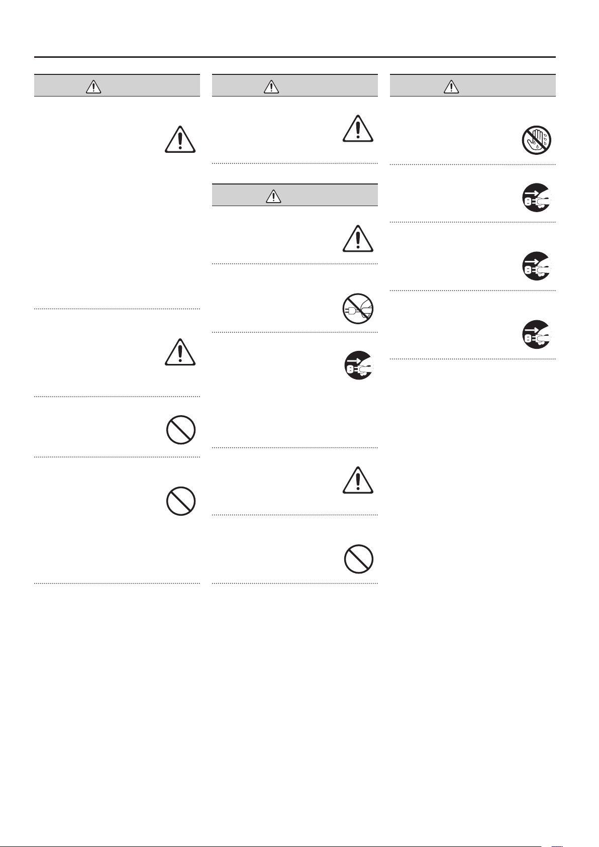
CAUTION
Do not connect or disconnect the power cord with wet
hands
Never handle the power cord or
its plugs with wet hands when
plugging into, or unplugging from,
an outlet or this unit.
Disconnect everything before moving the unit
Before moving the unit, disconnect
the power plug from the outlet,
and pull out all cords from external
devices.
Unplug the power cord from the outlet before
cleaning
Before cleaning the unit, turn it o
and unplug the power cord from the
outlet (p. 22).
If there is a possibility of lightning strike, disconnect
the power cord from the outlet
Whenever you suspect the
possibility of lightning in your area,
pull the plug on the power cord out
of the outlet.
4
Page 5
IMPORTANT NOTES
Power Supply
• Do not connect this unit to same electrical
outlet that is being used by an electrical
appliance that is controlled by an inverter
or a motor (such as a refrigerator, washing
machine, microwave oven, or air conditioner).
Depending on the way in which the electrical
appliance is used, power supply noise may
cause this unit to malfunction or may produce
audible noise. If it is not practical to use a
separate electrical outlet, connect a power
supply noise lter between this unit and the
electrical outlet.
• To prevent malfunction and equipment
failure, always make sure to turn o the power
on all your equipment before you make any
connections.
• Although the LCD and LEDs are switched
o when the unit is turned o, this does not
mean that the unit has been completely
disconnected from the source of power. If
you need to turn o the power completely,
rst turn o the unit’s switch, then unplug
the power cord from the power outlet. For
this reason, the outlet into which you choose
to connect the power cord’s plug should
be one that is within easy reach and readily
accessible.
• With the factory settings, the INTEGRA-7 will
automatically be switched o four hours after
you stop playing or operating the unit. If you
don’t want the unit to turn o automatically,
change the “Auto O” setting to “OFF” as
described on p. 55.
* The settings you were editing will be lost when the
unit is turned o. If you want to keep your settings,
you must save your settings before turning the unit
o.
Placement
• Using the unit near power ampliers (or
other equipment containing large power
transformers) may induce hum. To alleviate
the problem, change the orientation of this
unit; or move it farther away from the source
of interference.
• This device may interfere with radio and
television reception. Do not use this device in
the vicinity of such receivers.
• Noise may be produced if wireless
communications devices, such as cell phones,
are operated in the vicinity of this unit.
Such noise could occur when receiving or
initiating a call, or while conversing. Should
you experience such problems, you should
relocate such wireless devices so they are at
a greater distance from this unit, or switch
them o.
• When moved from one location to another
where the temperature and/or humidity is
very dierent, water droplets (condensation)
may form inside the unit. Damage or
malfunction may result if you attempt to use
the unit in this condition. Therefore, before
using the unit, you must allow it to stand for
several hours, until the condensation has
completely evaporated.
• Depending on the material and temperature
of the surface on which you place the unit, its
rubber feet may discolor or mar the surface.
You can place a piece of felt or cloth under the
rubber feet to prevent this from happening. If
you do so, please make sure that the unit will
not slip or move accidentally.
• Do not put anything that contains water on
this unit. Also, avoid the use of insecticides,
perfumes, alcohol, nail polish, spray cans, etc.,
near the unit. Swiftly wipe away any liquid
that spills on the unit using a dry, soft cloth.
Maintenance
• For everyday cleaning wipe the unit with a
soft, dry cloth or one that has been slightly
dampened with water. To remove stubborn
dirt, use a cloth impregnated with a mild, nonabrasive detergent. Afterwards, be sure to
wipe the unit thoroughly with a soft, dry cloth.
• Never use benzine, thinners, alcohol or
solvents of any kind, to avoid the possibility of
discoloration and/or deformation.
Repairs and Data
• Please be aware that all data contained in the
unit’s memory may be lost when the unit is
sent for repairs. Important data should always
be backed up USB ash drives, or written
down on paper (when possible). During
repairs, due care is taken to avoid the loss of
data. However, in certain cases (such as when
circuitry related to memory itself is out of
order), we regret that it may not be possible
to restore the data, and Roland assumes no
liability concerning such loss of data.
Additional Precautions
• Please be aware that the contents of memory
can be irretrievably lost as a result of a
malfunction, or the improper operation of
the unit. To protect yourself against the risk
of loosing important data, we recommend
that you periodically save a backup copy of
important data you have stored in the unit’s
memory on a USB ash drives.
• Unfortunately, it may be impossible to restore
the contents of data that was stored in the
unit’s memory, USB ash drives once it has
been lost. Roland Corporation assumes no
liability concerning such loss of data.
• Use a reasonable amount of care when using
the unit’s buttons, sliders, or other controls;
and when using its jacks and connectors.
Rough handling can lead to malfunctions.
• Never strike or apply strong pressure to the
display.
• When disconnecting all cables, grasp the
connector itself—never pull on the cable. This
way you will avoid causing shorts, or damage
to the cable’s internal elements.
• A small amount of heat will radiate from the
unit during normal operation.
• To avoid disturbing others nearby, try to keep
the unit’s volume at reasonable levels. You
may prefer to use headphones, so you do not
need to be concerned about those around
you.
• When you need to transport the unit, package
it in the box (including padding) that it came
in, if possible. Otherwise, you will need to use
equivalent packaging materials.
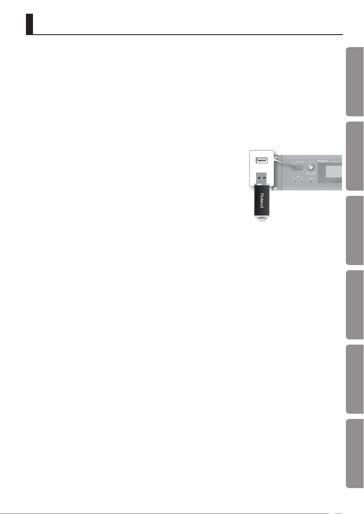
Before Using External Memories
Using External Memories
• Carefully insert the USB ash drives all the way
in—until it is rmly in place.
• Never touch the terminals of the USB ash
drives. Also, avoid getting the terminals dirty.
• USB ash drives are constructed using
precision components; handle the USB ash
drives carefully, paying particular note to the
following.
• To prevent damage to the cards from
static electricity, be sure to discharge
any static electricity from your own
body before handling the USB ash
drives.
• Do not touch or allow metal to come
into contact with the contact portion
of the USB ash drives.
• Do not bend, drop, or subject USB
ash drives to strong shock or
vibration.
• Do not keep USB ash drives in direct
sunlight, in closed vehicles, or other
such locations.
• Do not allow USB ash drives to
become wet.
• Do not disassemble or modify the
USB ash drives.
Handling DVDs
• Avoid touching or scratching the shiny
underside (encoded surface) of the disc.
Damaged or dirty DVD discs may not be
read properly. Keep your discs clean using a
commercially available DVD cleaner.
Quick Guide
Introduction Playing/Creating Sounds Use with a Computer Overall Settings Appendix
5
Page 6

IMPORTANT NOTES
Intellectual Property Right
• Do not use this product for purposes that
could infringe on a copyright held by a third
party. We assume no responsibility whatsoever
with regard to any infringements of third-party
copyrights arising through your use of this
product.
• The copyright of content in this product
(the sound waveform data, style data,
accompaniment patterns, phrase data, audio
loops and image data) is reserved by Roland
Corporation.
• Purchasers of this product are permitted
to utilize said content for the creating,
performing, recording and distributing original
musical works.
• Purchasers of this product are NOT permitted
to extract said content in original or modied
form, for the purpose of distributing recorded
medium of said content or making them
available on a computer network.
• Before you open the included DVD-ROM, you
must read the “license agreement.” Opening
the DVD-ROM will be taken to mean your
acceptance of the license agreement.
• MMP (Moore Microprocessor Portfolio)
refers to a patent portfolio concerned with
microprocessor architecture, which was
developed by Technology Properties Limited
(TPL). Roland has licensed this technology
from the TPL Group.
• Microsoft product screen shot(s) reprinted
with permission from Microsoft Corporation.
• This product contains eCROS integrated
software platform of eSOL Co.,Ltd. eCROS is a
trademark of eSOL Co., Ltd. in Japan.
• Roland, SuperNATURAL are either registered
trademarks or trademarks of Roland
Corporation in the United States and/or other
countries.
• Cakewalk is a registered trademark of
Cakewalk, Inc. in the United States.
• SONAR is a trademark of Cakewalk, Inc.
• Company names and product names
appearing in this document are registered
trademarks or trademarks of their respective
owners.
6
Page 7
Contents
IMPORTANT SAFETY INSTRUCTIONS . . . . . . . . . . . . . . . . . . . . . . . . . . . . . . 2
USING THE UNIT SAFELY . . . . . . . . . . . . . . . . . . . . . . . . . . . . . . . . . . . . . . . . . . 3
IMPORTANT NOTES . . . . . . . . . . . . . . . . . . . . . . . . . . . . . . . . . . . . . . . . . . . . . . 5
Quick Guide 8
Main Features . . . . . . . . . . . . . . . . . . . . . . . . . . . . . . . . . . . . . . . . . . . . . . . . . . . 8
Getting Ready . . . . . . . . . . . . . . . . . . . . . . . . . . . . . . . . . . . . . . . . . . . . . . . . . .10
Using the Internal Sounds . . . . . . . . . . . . . . . . . . . . . . . . . . . . . . . . . . . . . .12
Using the Expansion Sounds . . . . . . . . . . . . . . . . . . . . . . . . . . . . . . . . . . . .14
Creating a Sound Field with Depth . . . . . . . . . . . . . . . . . . . . . . . . . . . . . .16
Using SONAR LE to Play Sounds (Windows) . . . . . . . . . . . . . . . . . . . . .18
Introduction 20
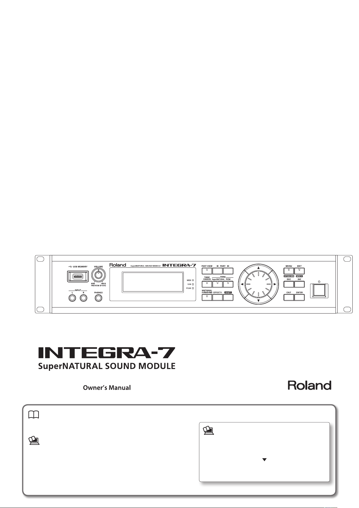
Panel Descriptions . . . . . . . . . . . . . . . . . . . . . . . . . . . . . . . . . . . . . . . . . . . . . .20
Front Panel . . . . . . . . . . . . . . . . . . . . . . . . . . . . . . . . . . . . . . . . . . . . . . . . . . . . .20
Turning the INTEGRA-7 On/O . . . . . . . . . . . . . . . . . . . . . . . . . . . .21
Playing the Demo Song . . . . . . . . . . . . . . . . . . . . . . . . . . . . . . . . . .21
Rear Panel Connections . . . . . . . . . . . . . . . . . . . . . . . . . . . . . . . . . . . . . . . .22
Getting Acquainted with the INTEGRA-7 . . . . . . . . . . . . . . . . . . . . . . . . .24
Studio Sets . . . . . . . . . . . . . . . . . . . . . . . . . . . . . . . . . . . . . . . . . . . . . . . . . . . . .24
How a Tone Is Structured . . . . . . . . . . . . . . . . . . . . . . . . . . . . . . . . .24
How a Studio Set Is Structured . . . . . . . . . . . . . . . . . . . . . . . . . . . .25
Eects . . . . . . . . . . . . . . . . . . . . . . . . . . . . . . . . . . . . . . . . . . . . . . . . . . . . . . . . .26
About Memory . . . . . . . . . . . . . . . . . . . . . . . . . . . . . . . . . . . . . . . . . . . . . . . . .27
Basic Operation . . . . . . . . . . . . . . . . . . . . . . . . . . . . . . . . . . . . . . . . . . . . . . . . .28
Switching Parts . . . . . . . . . . . . . . . . . . . . . . . . . . . . . . . . . . . . . . . . . . . . . . . .28
Moving the Cursor . . . . . . . . . . . . . . . . . . . . . . . . . . . . . . . . . . . . . . . . . . . . .28
Editing a Value . . . . . . . . . . . . . . . . . . . . . . . . . . . . . . . . . . . . . . . . . . . . . . . . .28
[SHIFT] Button Operations . . . . . . . . . . . . . . . . . . . . . . . . . . . . . . . . . . . . . .29
[ENTER] Button Operations . . . . . . . . . . . . . . . . . . . . . . . . . . . . . . . . . . . . .29
Saving . . . . . . . . . . . . . . . . . . . . . . . . . . . . . . . . . . . . . . . . . . . . . . . . . . . . . . . . .29
Assigning a Name . . . . . . . . . . . . . . . . . . . . . . . . . . . . . . . . . . . . . . . . . . . . . .29
Inserting or Deleting Characters . . . . . . . . . . . . . . . . . . . . . . . . . .29
Playing/Creating Sounds 30
Playing Sounds . . . . . . . . . . . . . . . . . . . . . . . . . . . . . . . . . . . . . . . . . . . . . . . . .30
Choosing a Studio Set . . . . . . . . . . . . . . . . . . . . . . . . . . . . . . . . . . . . . . . . . .30
Viewing a List of All Parts (PART VIEW -ALL- Screen) . . . . . . . . . . . . . .30
Viewing the Part Settings (PART VIEW Screen) . . . . . . . . . . . . . . . . . . .30
Temporarily Silencing a Part’s Sound (MUTE) . . . . . . . . . . . . . . . . . . . .30
Listening to Only One Part (SOLO) . . . . . . . . . . . . . . . . . . . . . . . . . . . . . .30
Choosing a Tone . . . . . . . . . . . . . . . . . . . . . . . . . . . . . . . . . . . . . . . . . . . . . . .31
Selecting Tones from a Tone List by Category . . . . . . . . . . . . . .31
Selecting Tones from a Tone List by Type/Bank . . . . . . . . . . . .31
Selecting Drum Kits from a Tone List . . . . . . . . . . . . . . . . . . . . . .31
Editing a Studio Set . . . . . . . . . . . . . . . . . . . . . . . . . . . . . . . . . . . . . . . . . . . . .32
Studio Set Common Settings . . . . . . . . . . . . . . . . . . . . . . . . . . . . . . . . . . .32
Editing the Part Settings . . . . . . . . . . . . . . . . . . . . . . . . . . . . . . . . . . . . . . . .32
Saving a Studio Set . . . . . . . . . . . . . . . . . . . . . . . . . . . . . . . . . . . . . . . . . . . . .34
Panning the Sound with Depth (MOTIONAL SURROUND Screen) .34
Editing the Motional Surround Settings . . . . . . . . . . . . . . . . . . .35
Turning Eects On/O . . . . . . . . . . . . . . . . . . . . . . . . . . . . . . . . . . . . . . . . . .35
Editing the Eects of a Studio Set (EFFECTS ROUTING Screen). . . .36
Editing the CHORUS Settings . . . . . . . . . . . . . . . . . . . . . . . . . . . . .36
Editing the REVERB Settings . . . . . . . . . . . . . . . . . . . . . . . . . . . . . .36
Adjusting the Overall Tone of the Audio Output (MASTER EQ) . . . .36
Initializing a Part . . . . . . . . . . . . . . . . . . . . . . . . . . . . . . . . . . . . . . . . . . . . . . .37
Initializing the Sound Controls . . . . . . . . . . . . . . . . . . . . . . . . . . . . . . . . . .37
Initializing a Studio Set . . . . . . . . . . . . . . . . . . . . . . . . . . . . . . . . . . . . . . . . .37
Editing a Tone . . . . . . . . . . . . . . . . . . . . . . . . . . . . . . . . . . . . . . . . . . . . . . . . . .38
Editing the Tones Assigned to a Part . . . . . . . . . . . . . . . . . . . . . . . . . . . .38
SuperNATURAL Acoustic Tone (SN-A) . . . . . . . . . . . . . . . . . . . . . .38
SuperNATURAL Synth Tone (SN-S) . . . . . . . . . . . . . . . . . . . . . . . . .38
SuperNATURAL Drum Kit (SN-D) . . . . . . . . . . . . . . . . . . . . . . . . . .39
PCM Synth Tone (PCMS) . . . . . . . . . . . . . . . . . . . . . . . . . . . . . . . . . .39
PCM Drum Kit (PCMD) . . . . . . . . . . . . . . . . . . . . . . . . . . . . . . . . . . . .40
Saving a Tone/Drum Kit. . . . . . . . . . . . . . . . . . . . . . . . . . . . . . . . . . . . . . . . .40
Editing the Eects of a Tone . . . . . . . . . . . . . . . . . . . . . . . . . . . . . . . . . . . .41
Editing the MFX (Multi-Eect) Settings . . . . . . . . . . . . . . . . . . . .41
Editing the COMP (Compressor) and EQ (Equalizer) Settings 41
Initializing a Tone. . . . . . . . . . . . . . . . . . . . . . . . . . . . . . . . . . . . . . . . . . . . . . .42
Initializing a Partial . . . . . . . . . . . . . . . . . . . . . . . . . . . . . . . . . . . . . . . . . . . . .42
Copying a Partial . . . . . . . . . . . . . . . . . . . . . . . . . . . . . . . . . . . . . . . . . . . . . . .42
Selecting the Partial to Edit . . . . . . . . . . . . . . . . . . . . . . . . . . . . . . . . . . . . .42
Use with a Computer 43
Using the INTEGRA-7 with Your Computer . . . . . . . . . . . . . . . . . . . . . . . .43
USB Driver . . . . . . . . . . . . . . . . . . . . . . . . . . . . . . . . . . . . . . . . . . . . . . . . . . . . .44
Connecting the INTEGRA-7 to Your Computer . . . . . . . . . . . . . . . . . . .44
USB MIDI . . . . . . . . . . . . . . . . . . . . . . . . . . . . . . . . . . . . . . . . . . . . . . . . . . . . . . .45
MIDI Signal Flow . . . . . . . . . . . . . . . . . . . . . . . . . . . . . . . . . . . . . . . . .45
Specifying the Output Destination of the Incoming
Messages . . . . . . . . . . . . . . . . . . . . . . . . . . . . . . . . . . . . . . . . . . . . . . . .45
USB AUDIO. . . . . . . . . . . . . . . . . . . . . . . . . . . . . . . . . . . . . . . . . . . . . . . . . . . . .46
Audio Signal Flow . . . . . . . . . . . . . . . . . . . . . . . . . . . . . . . . . . . . . . . .46
Specifying the Sampling Rate for USB Audio . . . . . . . . . . . . . .46
Applying Motional Surround to Sounds of an External Device . . . . .47
Connection Example . . . . . . . . . . . . . . . . . . . . . . . . . . . . . . . . . . . . . . . . . . .47
Overall Settings 48
Overall Settings . . . . . . . . . . . . . . . . . . . . . . . . . . . . . . . . . . . . . . . . . . . . . . . . . 48
System Settings . . . . . . . . . . . . . . . . . . . . . . . . . . . . . . . . . . . . . . . . . . . . . . . .48
Saving the System Settings . . . . . . . . . . . . . . . . . . . . . . . . . . . . . . . . . . . . .48
System Parameter . . . . . . . . . . . . . . . . . . . . . . . . . . . . . . . . . . . . . . . . . . . . . .48
Viewing the System Version . . . . . . . . . . . . . . . . . . . . . . . . . . . . . . . . . . . .49
Convenient Functions . . . . . . . . . . . . . . . . . . . . . . . . . . . . . . . . . . . . . . . . . . .50
Basic Procedure for Utility Operations . . . . . . . . . . . . . . . . . . . . . . . . . . .50
Initializing a USB Flash Drive (FORMAT USB MEMORY) . . . . . . . . . . .50
Exporting/Importing Sound Data . . . . . . . . . . . . . . . . . . . . . . . . . . . . . . .51
Exporting Sound Data (Export) . . . . . . . . . . . . . . . . . . . . . . . . . . .51
Importing Sound Data (Import) . . . . . . . . . . . . . . . . . . . . . . . . . . .51
Marking Multiple Items of Data . . . . . . . . . . . . . . . . . . . . . . . . . . .52
Deleting an Exported File . . . . . . . . . . . . . . . . . . . . . . . . . . . . . . . . .52
Renaming an Exported File . . . . . . . . . . . . . . . . . . . . . . . . . . . . . . .52
Backing Up User Data . . . . . . . . . . . . . . . . . . . . . . . . . . . . . . . . . . . . . . . . . .52
Backing Up to a USB Flash Drive (BACKUP) . . . . . . . . . . . . . . . .52
Restoring Backed-up Settings from a USB Flash Drive
(RESTORE) . . . . . . . . . . . . . . . . . . . . . . . . . . . . . . . . . . . . . . . . . . . . . . . .53
Deleting a Backup File . . . . . . . . . . . . . . . . . . . . . . . . . . . . . . . . . . . .53
Renaming a Backup File . . . . . . . . . . . . . . . . . . . . . . . . . . . . . . . . . .53
Backing Up USB Flash Drive Data to a Computer . . . . . . . . . . .53
Restoring Backed-up Data from a Computer to a USB
Flash Drive . . . . . . . . . . . . . . . . . . . . . . . . . . . . . . . . . . . . . . . . . . . . . . .54
Transmitting the Temporary Area’s Data to an External MIDI
Device (BULK DUMP) . . . . . . . . . . . . . . . . . . . . . . . . . . . . . . . . . . . . . . . . . . .54
Restoring the Factory Settings (FACTORY RESET) . . . . . . . . . . . . . . . .55
Making the Unit Automatically Turn O After a Time (Auto O) . .55
Appendix 56
Troubleshooting . . . . . . . . . . . . . . . . . . . . . . . . . . . . . . . . . . . . . . . . . . . . . . . .56
Error Message List . . . . . . . . . . . . . . . . . . . . . . . . . . . . . . . . . . . . . . . . . . . . . .58
MIDI Implementation Chart . . . . . . . . . . . . . . . . . . . . . . . . . . . . . . . . . . . . .59
Specications . . . . . . . . . . . . . . . . . . . . . . . . . . . . . . . . . . . . . . . . . . . . . . . . . . . 60
Index . . . . . . . . . . . . . . . . . . . . . . . . . . . . . . . . . . . . . . . . . . . . . . . . . . . . . . . . . . .61
Block Diagram . . . . . . . . . . . . . . . . . . . . . . . . . . . . . . . . . . . . . . . . . . . . . . . . . .62
Quick Guide
Introduction Playing/Creating Sounds Use with a Computer Overall Settings Appendix
7
Page 8
01 Main Features
The INTEGRA-7 is a completely new sound module that contains expressive and high-quality
SuperNATURAL sounds in addition to a rich sound library from the ever-popular SRX series, as
well as “Motional Surround,” which uses RSS (Roland Sound Space) technology to oer a new
type of sound eld.
The powerful SuperNATURAL sounds are reproduced using Motional Surround in a deeper and
even more natural sound eld, allowing a truly new dimension of sound creation.
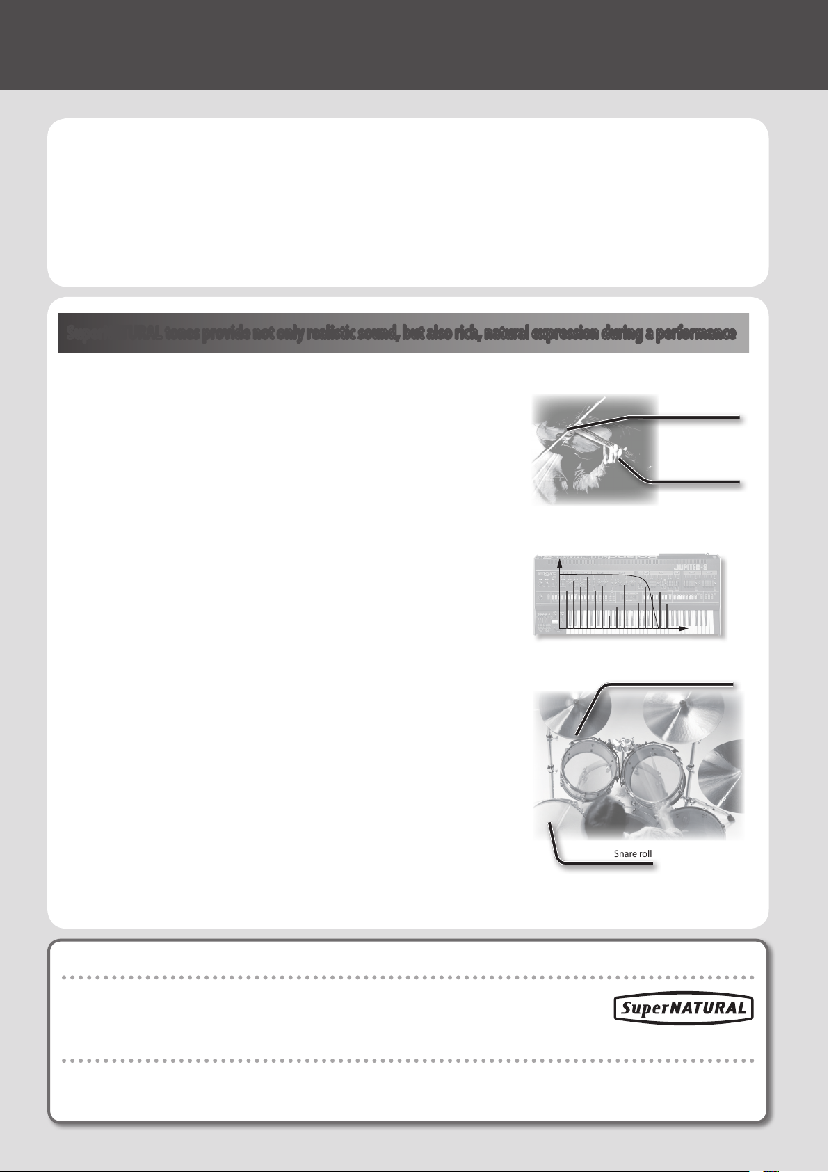
SuperNATURAL tones provide not only realistic sound, but also rich, natural expression during a performance
SuperNATURAL Acoustic Tones
The SuperNATURAL acoustic tones built into the INTEGRA-7 do not merely reproduce the
sound of acoustic instruments, they also use Behavior Modeling Technology to simulate
the characteristic behavior of an instrument when it is played.
A dedicated sound engine tuned specically for each type of instrument analyzes the
phrases performed by the player, automatically dierentiating between chordal and
melodic playing to produce the optimal expression for a performance.
For example, the “violin” SuperNATURAL acoustic tone allows your conventional keyboard
playing to create a realistically expressive solo violin sound that sounds as if it were being
played by a violinist.
Crescendo
Glissando technique
Vibrato
SuperNATURAL Synth Tones
These are SuperNATURAL synth tones, which realistically reproduce sounds ranging from
vintage analog synths to digital synths. Each synth tone consists of three sets of OSC,
FILTER, AMP, and LFO, meaning that powerful synth sounds can be created using just a
single synth tone.
In addition, the behaviors of the oscillators and lters of analog synths have been analyzed,
allowing their distinctive sounds to be reproduced. The INTEGRA-7 contains more than
1,000 sounds, which cover every type of synth sound from analog to digital.
SuperNATURAL Drum Kits
The SuperNATURAL drum kits built into the INTEGRA-7 provide not only realistic, highquality sound, they also boast smooth tonal change in response to your playing dynamics
or to repeated strikes.
For example, the crash cymbal can be played not only by a powerful strike, but will also
respond to a light touch. The ride cymbal will shift through a variety of tones in response
to your varying dynamics. The drum will also respond appropriately to repeated strikes, so
press rolls, ams, and ll-ins will sound natural.
Repeated strikes on cymbal edge
Snare roll
What is SuperNATURAL?
These are proprietary Roland sounds created using Behavior Modeling Technology, which enables
natural and rich expression that was dicult to achieve on earlier sound generators.
What is Behavior Modeling Technology?
Not only physical modeling of the instruments, Roland takes it a step further by modeling the instrument’s distinctive behavior
that responds to how the performer plays, resulting in true-to-life, expressive sounds in realtime.
8
Page 9
The INTEGRA-7 brings together the classic sounds of Roland synthesizers (PCM Tones)
Classic preset sounds from past models of Roland synthesizers, as well as the
sounds from the entire SRX series wave expansion boards have been included,
especially tuned for the INTEGRA-7.
The sound data includes PCM synth tones and PCM drum kits, and can be called
up from the preset banks and expansion banks.
Quick Guide
The sounds of the SRX series are organized into SRX-01 through SRX-12 just as on
the actual SRX models; when you load an entire title of sound data into one of the
four virtual slots, those sounds will be available for use.
PCM Synth Tones
These are sounds that were called “patches” on previous Roland synthesizers; they have been tuned specically for the INTEGRA-7. One PCM
synth tone can consist of up to four partials (waves).
PCM Drum Kits
These were called “rhythm sets” on previous Roland synthesizers; they have been tuned specically for the INTEGRA-7. A drum kit is a group
of multiple percussion instrument sounds assigned so that a dierent percussion instrument will be heard depending on the key (note
number) you play.
Multi-eects Usable for 16 Parts Simultaneously
All of the tones (SuperNATURAL tones and PCM tones) built into the INTEGRA-7 includes dedicated multi-eect settings.
Since a multi-eect can be used by each of the 16 parts simultaneously, the most appropriate multi-eect settings will be called up when you
select a tone.
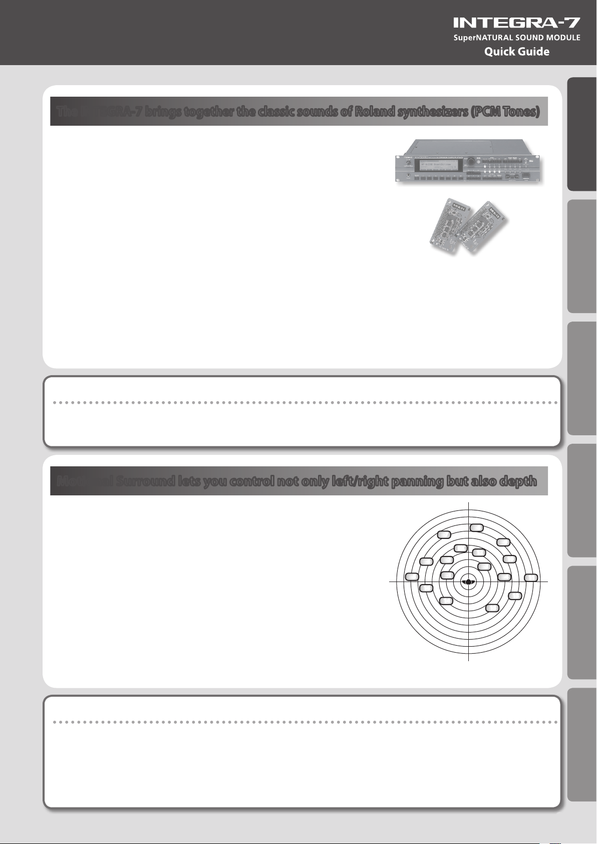
Motional Surround lets you control not only left/right panning but also depth
The INTEGRA-7 supports two-channel output as well as 5.1 channel surround.
Using the Motional Surround function gives you even more freedom to
manipulate the spatial position of each part (p. 16).
Until now, sounds in a MIDI sound module could only be panned between left
and right. However, the INTEGRA-7 lets you specify the depth as well, allowing
you to create a sound eld that has unprecedented depth and spaciousness.
For example, a solo instrument can be placed nearby, while the ensemble or
percussion instruments are placed at a distance, thus creating a sound eld
with greater depth; or you can create a perceptual space that extends beyond
the actual speakers.
This eect can be applied to external input signals as well, so you can use it on
audio tracks as well as on the sounds of the sound module.
7
6
5
16
14
8
EX
2
1
9
12
10
3
4
13
15
Introduction Playing/Creating Sounds Use with a Computer Overall Settings Appendix
11
* To use the Motional Surround function, turn the [MOTIONAL SURROUND] button ON (p. 16, p. 34).
What is Motional Surround?
In the sounds we hear every day, the “direct sound,” which reaches our ears directly from the sound source, is combined with the “reected
sound,” which has bounced o various objects in the environment. The combination of these two types of sound gives us a sense of the
distance between us and the sound source. Motional Surround takes into account the state of the actual room, and simulates the way in which
objects in the room reect the sound, thus creating a three-dimensional sound eld.
In order to create the most realistic sound eld, the INTEGRA-7 contains a processor that generates a sense of distance, reverberation, and
directionality, and also performs format conversion.
As appropriate for your playback system, Motional Surround supports both 5.1 channel and two-channel output.
9
Page 10
02 Getting Ready
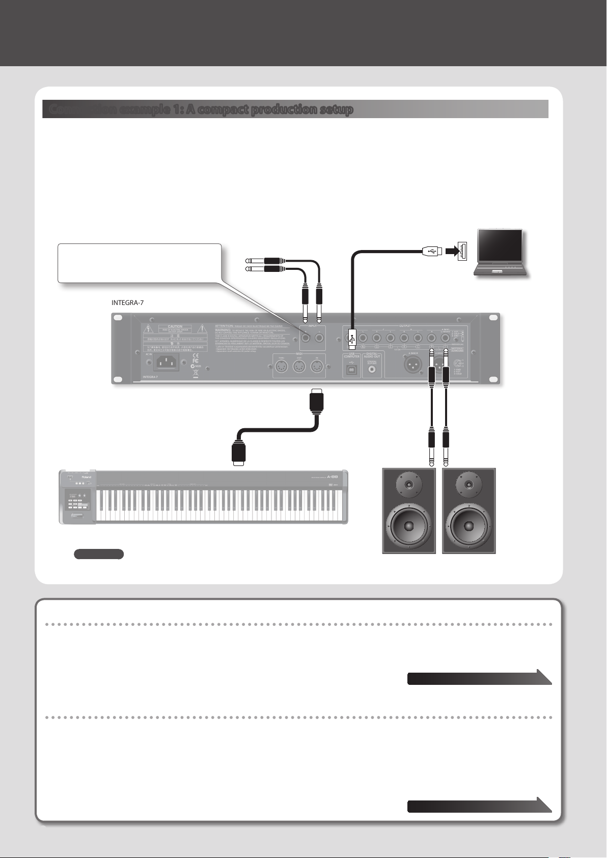
Connection example 1: A compact production setup
Here’s an example of the use of the INTEGRA-7 for high-quality music production.
This is an easy way to set up a full-edged music production system based on the INTEGRA-7 simply by connecting it to DAW
software in your computer and to a MIDI keyboard.
* If you turn the INTEGRA-7’s USB-MIDI Thru setting “ON,” you’ll be able to use it as a MIDI interface (p. 45).
Audio input from an external device can be
panned spatially using the Ext part of the
Motional Surround function (p. 47).
INTEGRA-7
MIDI keyboard
Connect an instrument
or other device.
MIDI IN
MIDI OUT
Computer
Sequencer software
such as SONAR
To powered speakers
or amp
REFERENCE
For details on connections, refer to “Rear Panel Connections” (p. 22).
Connecting your computer via USB
If you connect the INTEGRA-7 to your computer using a USB cable, you’ll be able to use your DAW software to record performance data (MIDI
data) from a MIDI keyboard connected to the INTEGRA-7, and use performance data (MIDI data) played back by the DAW software to play the
sound generator of the INTEGRA-7 (USB MIDI).
The INTEGRA-7 will operate as a MIDI sound module when it is connected to your computer with a
USB cable.
To use USB audio functionality
You’ll need to install a driver in order to use the USB audio functionality of the INTEGRA-7.
This driver can be downloaded from the Roland website.
Roland website
http://www.roland.com/support/en/
For the installation procedure, refer to the Readme le that was extracted along with the installer.
You need to set the “Ext Part Source Select” parameter under “Volume and Pitch Settings
(SOUND)” (p. 48) to “USB AUDIO.”
10
“USB MIDI” page 45
“USB AUDIO” page 46
Page 11
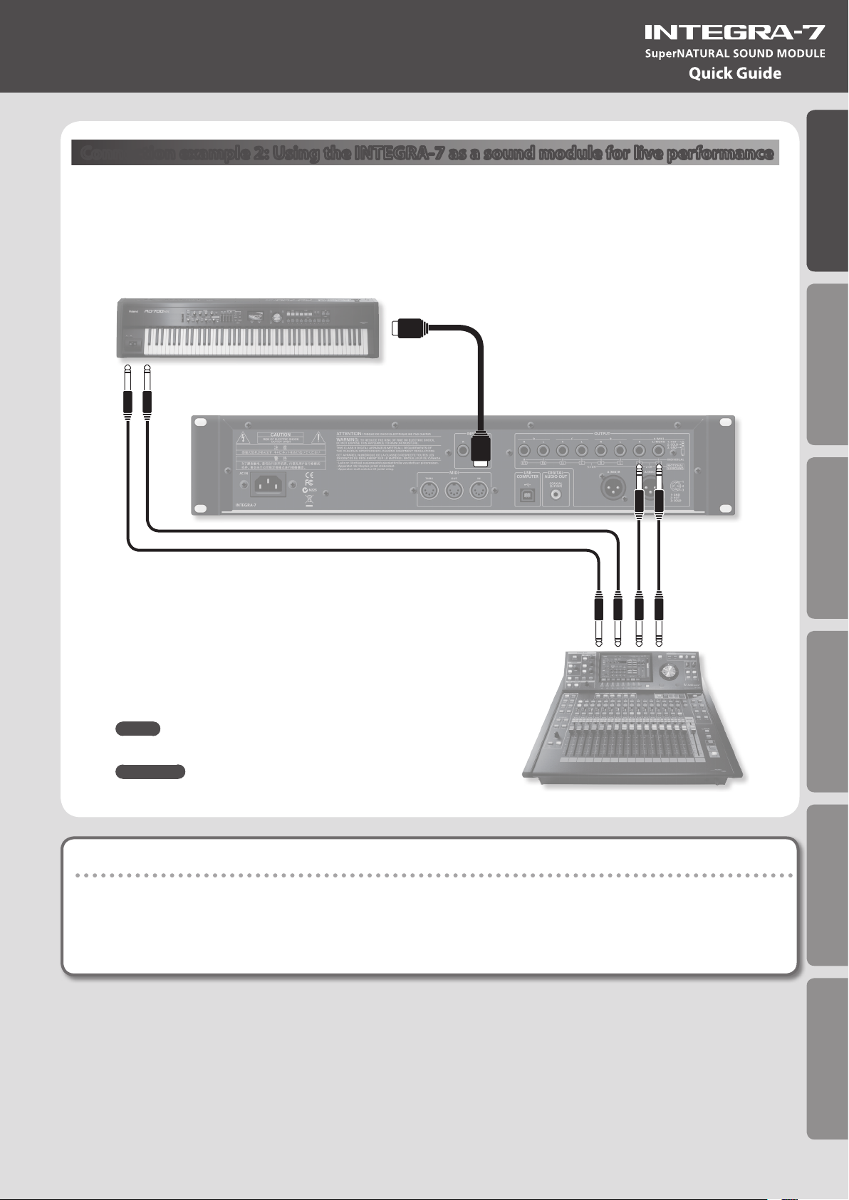
Connection example 2: Using the INTEGRA-7 as a sound module for live performance
Here’s a connection example of including the INTEGRA-7 in an existing live performance system.
In this example, the MIDI connector is used to connect a keyboard or another sound module.
Keyboard
MIDI OUT
OUTPUT
Quick Guide
Introduction Playing/Creating Sounds Use with a Computer Overall Settings Appendix
INTEGRA-7
MEMO
Turn the INTEGRA-7’s USB-MIDI Thru setting “OFF” (p. 45).
REFERENCE
For details on connections, refer to “Rear Panel Connections” (p. 22).
MIDI IN
INPUT
To mixer, or amp
About MIDI
MIDI (Musical Instrument Digital Interface) is a standard specication that allows musical data to be transferred between electronic musical
instruments and computers. If a MIDI cable is connected between devices equipped with MIDI connectors, you’ll be able to play multiple
devices from a single MIDI keyboard, perform ensembles using multiple MIDI instruments, program the settings to change automatically as the
song progresses, and more.
11
Page 12

03 Using the Internal Sounds
About the INTEGRA-7’s screen
When you turn on the INTEGRA-7, the top screen will appear. You can choose the type of top screen (p. 48).
Part number
Tone type
Tone bank
Mute on/o of each part
(p. 30)
The “*” indicates an edit
Solo on/o of the current
part (p. 30)
Playing SuperNATURAL tones
1. Press the [SuperNATURAL] button.
The tone of the selected part will change to a SuperNATURAL
tone.
The display will show the SuperNATURAL tone list.
2. Use the cursor buttons to change the type or the bank.
3. Use the value dial to select a tone.
4. Press the [ENTER] button.
The part’s tone will be selected.
The “!” indicates use of
sound that’s not loaded
Part number
Tone number and tone
name of the current part
Part level meter
External audio input level
Playing PCM tones
1. Press the [PCM] button.
The tone of the selected part will change to a PCM tone.
The display will show the PCM tone list.
2. Use the cursor buttons to change the type or the bank.
3. Use the value dial to select a tone.
4. Press the [ENTER] button.
The part’s tone will be selected.
MEMO
Tone Preview function
By pressing the [VOLUME] knob you can audition the tone of the selected part.
Connecting a MIDI keyboard and performing
Connection example
OUTPUT
Keyboard
MIDI IN
INTEGRA-7
* Depending on the settings of the connected MIDI keyboard, note messages played on the keyboard might be transmitted on several
channels. Make settings on your MIDI keyboard so that the MIDI output is appropriate.
12
OUTPUT A (MIX)
To powered speakers
or amp
Page 13
Types and Features of the Internal Sounds
For details on how to select sounds, refer to p. 12.
SuperNATURAL Acoustic Tone (SN-A)
Changes in dynamics
From delicate pianissimo to powerful fortissimo, these tones provide natural timbral variation (dynamics) that goes beyond
mere changes in volume.
* Dynamics can be controlled by note-on velocity, modulation controller (CC01), and expression (CC11).
While a note is sounding, you can operate the modulation controller (CC01) or expression pedal (CC11) to continuously
control the dynamics (except for struck-string instruments and plucked-string instruments).
Legato
By playing legato (the technique of sending the next note-on before releasing the previous key) you can produce smooth
transitions between notes.
* To obtain the legato eect, set the Mono/Poly of the part settings to “MONO” and set the Legato switch to “ON” (p. 32).
Switching variation sounds
Each instrument provides eective performance variation sounds; you can use control changes CC80, CC81, CC82, CC83
(Tone Variation 1–4) to switch instantly between them as you play.
Quick Guide
Introduction Playing/Creating Sounds Use with a Computer Overall Settings Appendix
SuperNATURAL Synth Tone (SN-S)
Realistic lter behavior
The INTEGRA-7 contains lters that simulate the classic analog synths of the past, producing natural-sounding change when
you vary the cuto frequency (CC74) or resonance (CC71).
SuperNATURAL Drum Kit (SN-D)
Changes in dynamics
From delicate pianissimo to powerful fortissimo, these sounds provide natural timbral variation (dynamics) that goes beyond
mere changes in volume.
Eliminates boring uniformity even for repeated attacks
To avoid monotonous uniformity, the sense of attack will dier for each strike.
Ambience control for the entire kit
The drum kit consists of multiple drum instruments such as snare, kick, and hi-hat. You can control the resonance between
instruments and the ambience of the room.
PCM Synth Tone (PCMS) / PCM Drum Kit (PCMD)
The PCM synth tones and PCM drum kits are what were called patches and rhythm sets on previous Roland synthesizers; they
are remarkable for their high quality and their rich variations. Many classic sounds tuned specically for the INTEGRA-7 are
included.
13
Page 14
04 Using the Expansion Sounds
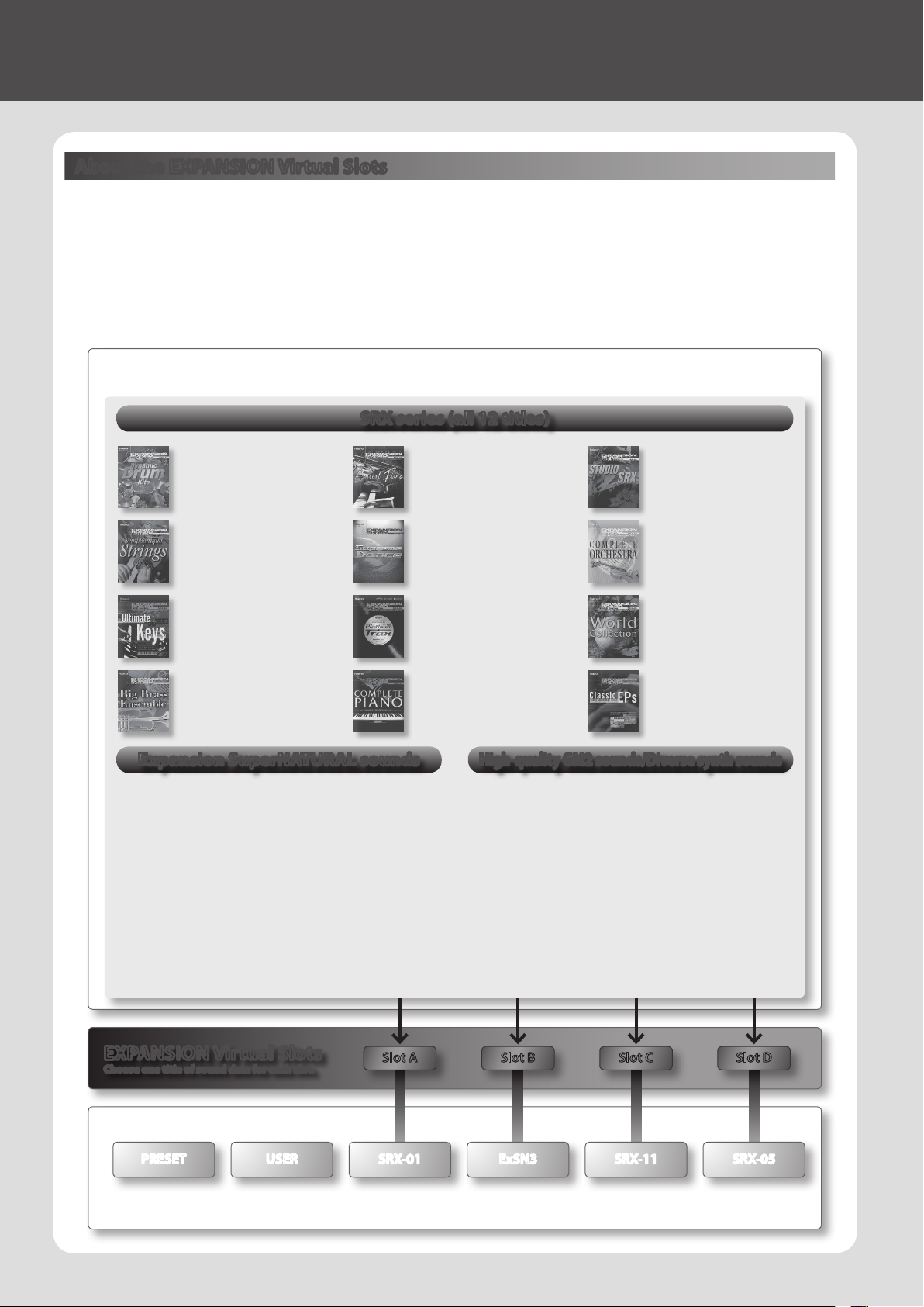
About the EXPANSION Virtual Slots
The INTEGRA-7 contains all the sound data from the entire SRX series of wave expansion boards, as well as expansion
SuperNATURAL tones.
You can add these sounds by loading each title into one of the INTEGRA-7’s four EXPANSION Virtual Slots (Slot A–D). (In other
words, sound data for up to four titles can be used simultaneously.)
The sound data includes tones (patches), drum kits (rhythm sets), instruments, and wave (waveform) data. (The content will
vary by title.)
Sound data (expansion)
The INTEGRA-7 contains all SRX series sound data, expansion SuperNATURAL tones, and high-quality GM2 sounds.
SRX series (all 12 titles)
SRX-01
Dynamic Drum Kits
PCM Synth Tone : 41
PCM Drum Kit : 79
SRX-04
Symphonique Strings
PCM Synth Tone : 128
SRX-07
Ultimate Keys
PCM Synth Tone : 475
PCM Drum Kit : 11
SRX-10
Big Brass Ensemble
PCM Synth Tone : 100
Expansion SuperNATURAL sounds
ExSN1
ExSN2
ExSN3
ExSN4
ExSN5
ExSN6
Ethnic (SuperNATURAL Acoustic Tone : 17)
Ethnic instruments such as kalimba and santur
Wood Winds (SuperNATURAL Acoustic Tone : 17)
Woodwinds such as sax and ute
Session (SuperNATURAL Acoustic Tone : 50)
Electric guitar and bass
A. Guitar (SuperNATURAL Acoustic Tone : 12)
Acoustic guitar
Brass (SuperNATURAL Acoustic Tone : 12)
Brass instruments such as trumpet and trombone
SFX (SuperNATURAL Drum Kit : 7)
Realistic sound eects
SRX-02
Concert Piano
PCM Synth Tone : 50
SRX-05
Supreme Dance
PCM Synth Tone : 312
PCM Drum Kit : 34
SRX-08
Platinum Trax
PCM Synth Tone : 448
PCM Drum Kit : 21
SRX-11
Complete Piano
PCM Synth Tone : 42
High-quality GM2 sounds/Diverse synth sounds
ExPCM
SRX-03
Studio SRX
PCM Synth Tone : 128
PCM Drum Kit : 12
SRX-06
Complete Orchestra
PCM Synth Tone : 449
PCM Drum Kit : 5
SRX-09
World Collection
PCM Synth Tone : 414
PCM Drum Kit : 12
SRX-12
Classic EPs
PCM Synth Tone : 50
HQ GM2 + HQ PCM Sound Collection
High-quality GM2 sounds and a variety of synth
sounds
HQ GM2 (GM2#)
PCM Synth Tone : 256
PCM Drim Kit : 9
HQ PCM (ExPCM)
PCM Synth Tone : 512
PCM Drum Kit : 19
* ExPCM uses all four slots.
14
EXPANSION Virtual Slots
Choose one title of sound data for each slot.
Slot CSlot BSlot A
Slot D
Sound banks (example)
PRESET USER SRX-01 ExSN3 SRX-11
When you load expansion sound data into the EXPANSION Virtual Slots (A–D), the loaded sounds will be available for selection from the corresponding
sound bank (title is displayed).
SRX-05
Page 15

Loading sound data into an EXPANSION Virtual Slot
1. Press the [MENU] button.
2. Choose “EXPANSION” and press the [ENTER] button.
The EXPANSION screen will appear. This screen shows the sounds that are
loaded into each EXPANSION Virtual Slot.
3. In the VIRTUAL SLOTS area, move the cursor to the slot that
you want to load, and use the [DEC] [INC] buttons to select the
desired sound data.
MEMO
To view the expansion sound list, move the cursor to “INFO/LIST” and
press the [ENTER] button.
Sound data to be loaded
An “*” symbol is shown at the left of
the name of edited sound data.
4. Move the cursor to “LOAD” and press the [ENTER] button.
A message will ask “Are you sure?”
5. To execute, choose “OK” and press the [ENTER] button.
MEMO
You can also access the EXPANSION (VIRTUAL SLOT) screen by holding down the [SHIFT] button and pressing the [MENU] button.
Using SRX series sounds
SRX series sounds can be selected in the same way as PCM sounds.
Select one SRX bank (SRX-01–SRX-12) to use the sounds that have been loaded into an EXPANSION Virtual Slot.
* Some SRX titles have no PCM drum kit (PCMD).
Quick Guide
Introduction Playing/Creating Sounds Use with a Computer Overall Settings Appendix
Using SuperNATURAL sounds
SuperNATURAL sounds that have been loaded can be selected in the same way as the SuperNATURAL sounds of preset
memory or user memory.
Select one ExSN bank (ExSN1–SxSN6) to use the sounds that have been loaded into an EXPANSION Virtual Slot.
* ExSN 1--5 contain only SuperNATURAL acoustic tones, and ExSN6 contains only SuperNATURAL drum kits.
Using ExPCM sounds
Loaded ExPCM sounds can be selected in the same way as PCM sounds.
The sounds loaded into the EXPANSION Virtual Slot can be made available for use by selecting the ExPCM bank.
When you load the ExPCM sounds, the “GM2” bank indication will change to “GM2#”, and high-quality GM2 sounds will be
available.
* The ExPCM sounds use all four slots.
* You can’t edit ExPCM tones.
If you want the expansion sounds to be loaded automatically at start-up
You can have the INTEGRA-7 automatically load specied sound data into the EXPANSION Virtual Slots upon startup.
* With the factory settings, the sound data will be loaded.
1. Press the [MENU] button.
2. In the MENU screen, choose “SYSTEM” and press the [ENTER] button.
3. Select the desired sound data for Startup Exp Slot A–D.
4. Hold down the [SHIFT] button and press the [EDIT] button to save the settings.
15
Page 16
05 Creating a Sound Field with Depth
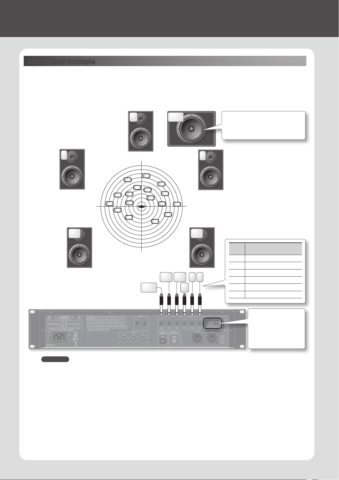
Connection example
Here’s an example of using the INTEGRA-7’s Motional Surround function for 5.1 channel surround output.
Place your speakers as shown in the illustration.
To use the Motional Surround function, press the [MOTIONAL SURROUND] button to turn the Motional Surround function on.
L
6
5
16
Ls Rs
* Dolby Digital and DTS are not supported. Please
use analog cables to connect ve speakers and a
subwoofer.
C
LFE
It’s best to place the subwoofer at the same
distance as the satellite speakers, with the
listening position at the center.
R
7
14
8
EX
2
1
LFE
9
12
10
3
4
11
13
15
Jack
Explanation
name
L Front left output
R Front right output
R L
LsRs
C
C Front center output
Ls Rear left output
Rs Rear right output
LFE Subwoofer output
REFERENCE
• For more about connections, refer to “Rear Panel Connections” (p. 22).
• For more about front center speaker (C jack) and subwoofer (LFE jack) output settings, refer to “Motional Surround Settings (MOTIONAL
SURROUND)” (p. 49) in System Settings.
About the monitoring environment
• An acoustically dead space with minimal reverberation is ideal as a monitoring room.
• You should monitor at the sweet spot of your speaker system.
Concerning perception of a sound image’s location
• The ease with which one can sense where a sound emanates from can dier depending on the sound.
For example, it is dicult to perceive the spatial location of low-frequency sounds or sounds that have relatively little harmonic content
(such as sine waves). Conversely, it tends to be easier to determine the location of sounds having rich harmonic content and a distinct
attack.
• Perception of front/back localization can dier between individuals.
16
If you want to use Motional
Surround with a two-channel
system, connect your
speakers to the A (MIX) L
(MONO)/R jacks.
Page 17
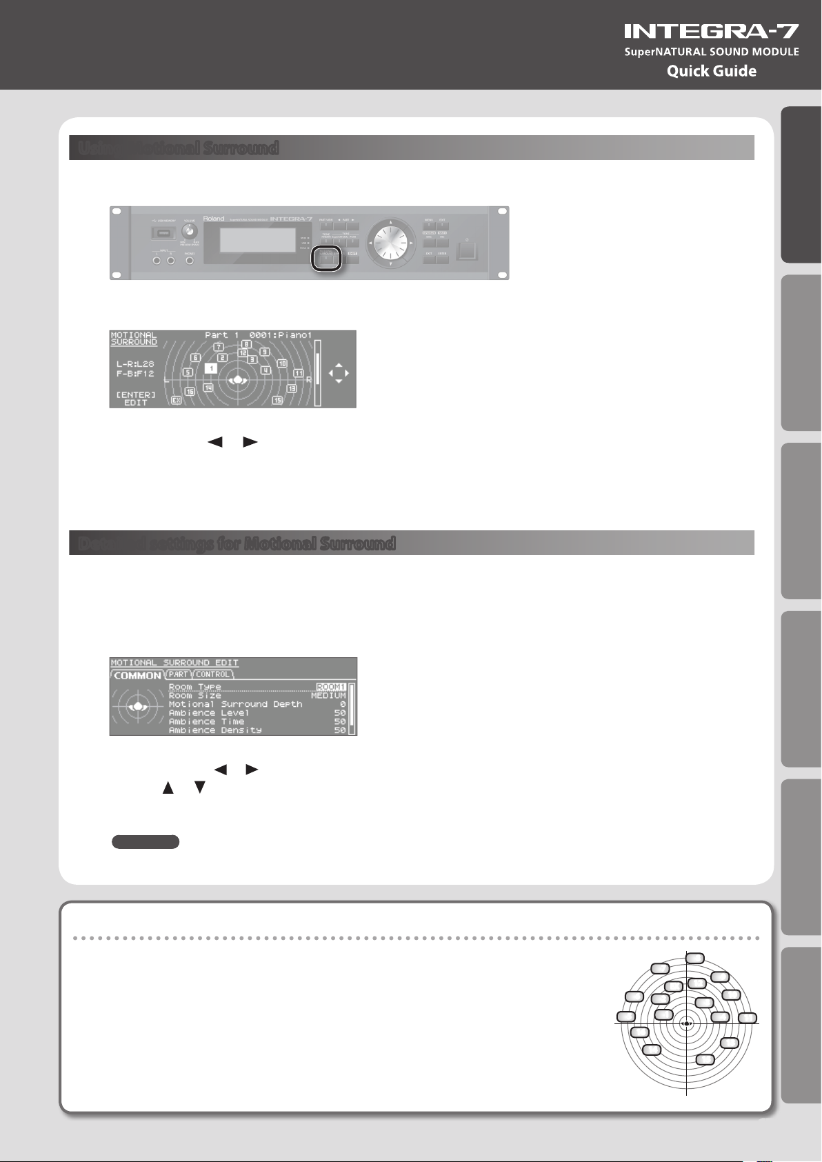
Using Motional Surround
1. Press the [MOTIONAL SURROUND] button.
Quick Guide
Motional Surround will turn on, and the MOTIONAL SURROUND screen will appear.
2. Use the PART [ ] [ ] buttons to select a part.
The selected part number will be highlighted.
3. Use the cursor buttons to specify the sound’s panning (front/rear, left/right).
Detailed settings for Motional Surround
Here’s how to make detailed settings for the ambience eect and for each part.
1. In the MOTIONAL SURROUND screen, press the [ENTER] button.
The MOTIONAL SURROUND EDIT screen will appear.
Introduction Playing/Creating Sounds Use with a Computer Overall Settings Appendix
2. Use the cursor [ ] [ ] buttons to select the “COMMON,” “PART,” or “CONTROL” tab, and use the
cursor [ ] [ ] buttons to select a parameter.
3. Use the value dial to edit the setting.
REFERENCE
For details on the each parameters, refer to p. 35.
What is Motional Surround?
The INTEGRA-7 supports two-channel and 5.1 channel surround output. By using the Motional
Surround function, you can freely and easily control the placement of each part (p. 34).
While conventional systems allow sound to be placed only in the left/right direction, this new
function adds the front/back dimension, enabling you to play sounds that you’ve freely placed
in a soundscape with depth. Additionally, you can specify the type and size of room; this allows
you to adjust the acoustics as appropriate for your song, ranging from an intimate room to a
large concert hall.
6
5
16
14
8
7
12
EX
2
3
1
15
9
10
4
11
13
17
Page 18
06 Using SONAR LE to Play Sounds (Windows)
Installing SONAR LE
Install the included SONAR LE in your computer.
For details on installation and main operations, refer to the manual included on the SONAR LE DVD-ROM.
* SONAR LE is for Windows only. If you are a Mac user, you’ll need to obtain DAW software separately.
Audio and MIDI settings
Important!
Before you begin making settings, download the INTEGRA-7’s USB driver from the Roland website and install it (p. 43). When
installing the driver, change the USB Driver setting to “VENDER” (p. 44).
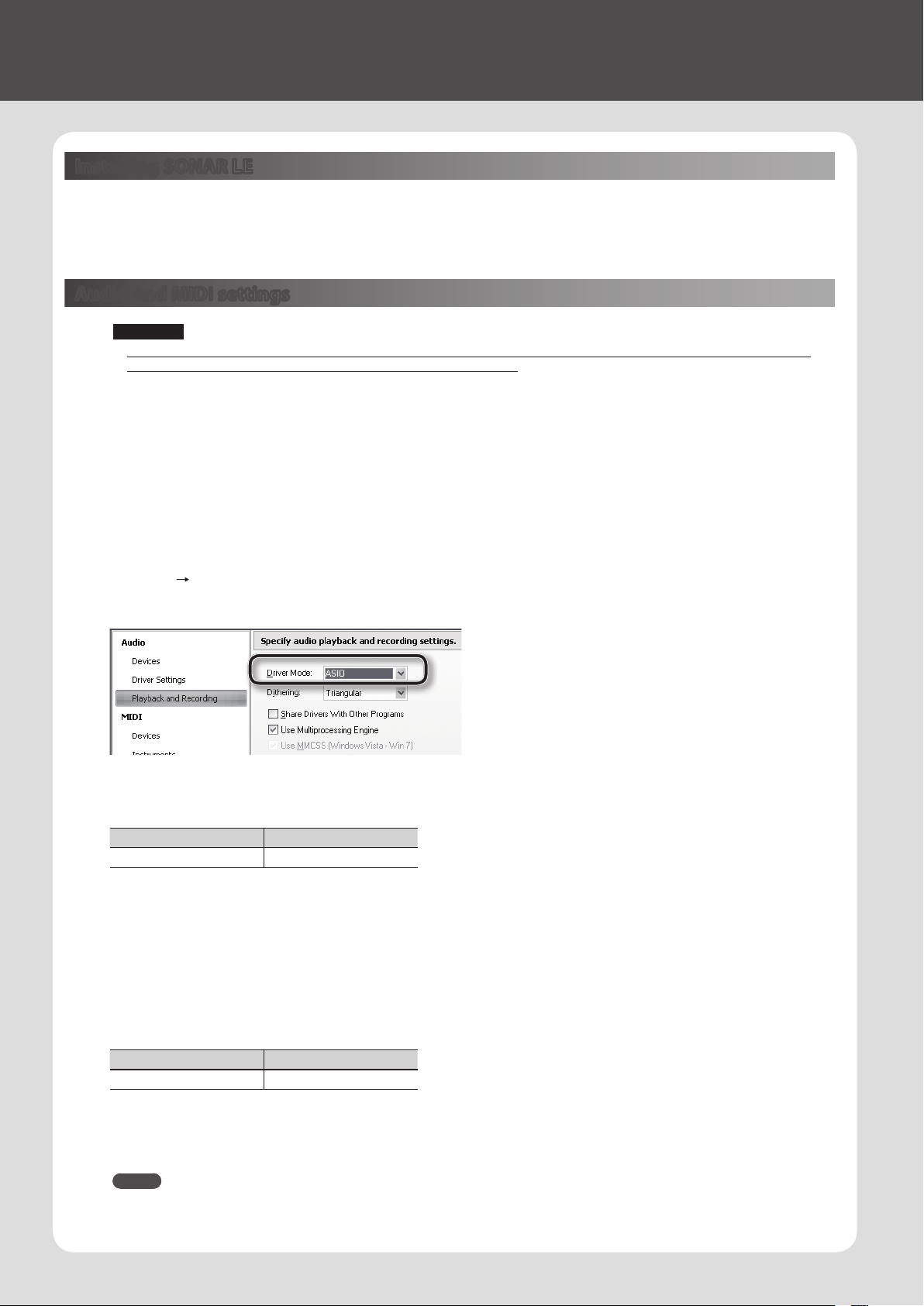
Audio settings
Specify the INTEGRA-7 as the audio input and output.
1. Use a USB cable to connect the INTEGRA-7 to your computer.
Connect the INTEGRA-7 to your computer as shown in “Connection example 1: A compact production setup” (p. 10).
2. Start up SONAR.
3. The “Quick Start” dialog box will appear. Click [Close].
4. Click [Edit] [Preferences] to access the “Preferences” dialog box.
5. From the “Audio” list at the left of the screen, choose [Options]. Choose “ASIO” as the driver mode, and click [Apply].
6. In the “Audio” section of the list at the left of the screen, choose [Select Device]. Clear the check marks from audio devices
you’re not using, and enter a check mark only for the INTEGRA-7.
Input device Output device
INTEGRA-7 IN INTEGRA-7 OUT
* When selecting INTEGRA-7 OUT as the output device, you need to set the “Ext Part Source Select” parameter under “Volume and Pitch
Settings (SOUND)” (p. 48) to “USB AUDIO.”
MIDI settings
Next, you need to specify the INTEGRA-7 as the MIDI input and output device.
7. In the “MIDI” section of the list at the left of the screen, choose [Select Device]. Enter a check mark for the INTEGRA-7, and
clear the check marks from MIDI devices you’re not using.
Input device Output device
INTEGRA-7 INTEGRA-7
* When handling ordinary performance data, use “INTEGRA-7.”
Use “INTEGRA-7 CTRL” (Windows only) when handling control data, such as
that for MOTIONAL SURROUND.
8. Click [Apply].
9. In the “Preferences” dialog box, click [Close].
MEMO
If the INTEGRA-7 is not shown in the list of devices, close SONAR and try the operation again from step 2.
If it is still not shown, the driver installation might not have completed successfully. Uninstall the driver, and then install the driver once again.
18
Page 19
Recording on a MIDI track
Connect the INTEGRA-7 to your computer as shown in “Connection example 1: A compact production setup” (p. 10).
* Turn the INTEGRA-7’s USB-MIDI Thru setting (p. 49) ON.
1. In the [File] menu, click [New].
The “Create a New Project” dialog box will appear.
2. In the “Template” area, choose [Normal]; in the “Name” area, enter a name for
your project and then click [OK].
Quick Guide
3. Record a MIDI track in SONAR.
For details on how to record, refer to SONAR’s help.
4. Play back SONAR.
You’ll hear sound from the INTEGRA-7.
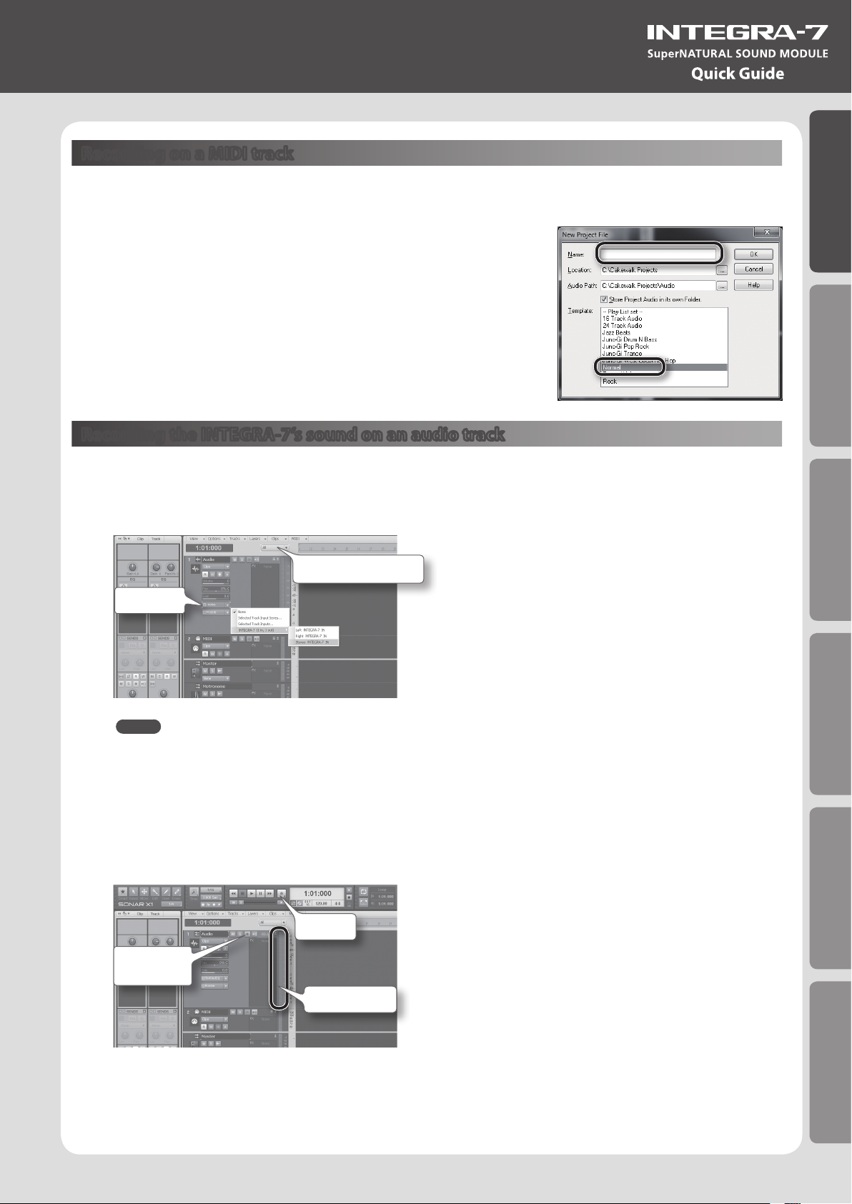
Recording the INTEGRA-7’s sound on an audio track
1. In the [Insert] menu, choose [Audio Track].
One audio track will be added.
2. For the input eld of the audio track, choose “Stereo INTEGRA-7 IN.”
Track control list
Input eld
MEMO
If the input eld is not shown, click the track control list and choose “ALL.”
Introduction Playing/Creating Sounds Use with a Computer Overall Settings Appendix
3. Adjust the recording level.
Put the track in recording-standby mode, then get the INTEGRA-7 to start playing. Adjust the input level of the SONAR so that the level meter
reaches approximately -6 during the loudest passages.
* For details on the recording procedure, refer to SONAR’s help.
4. Record.
Put the track in recording-standby mode, and press the record button of the transport module to begin recording.
Record
Recordingstandby
Level meter
5. When the song ends, press the stop button.
Recording will stop, and the recorded sound will be shown as a waveform in the audio track of SONAR.
19
Page 20
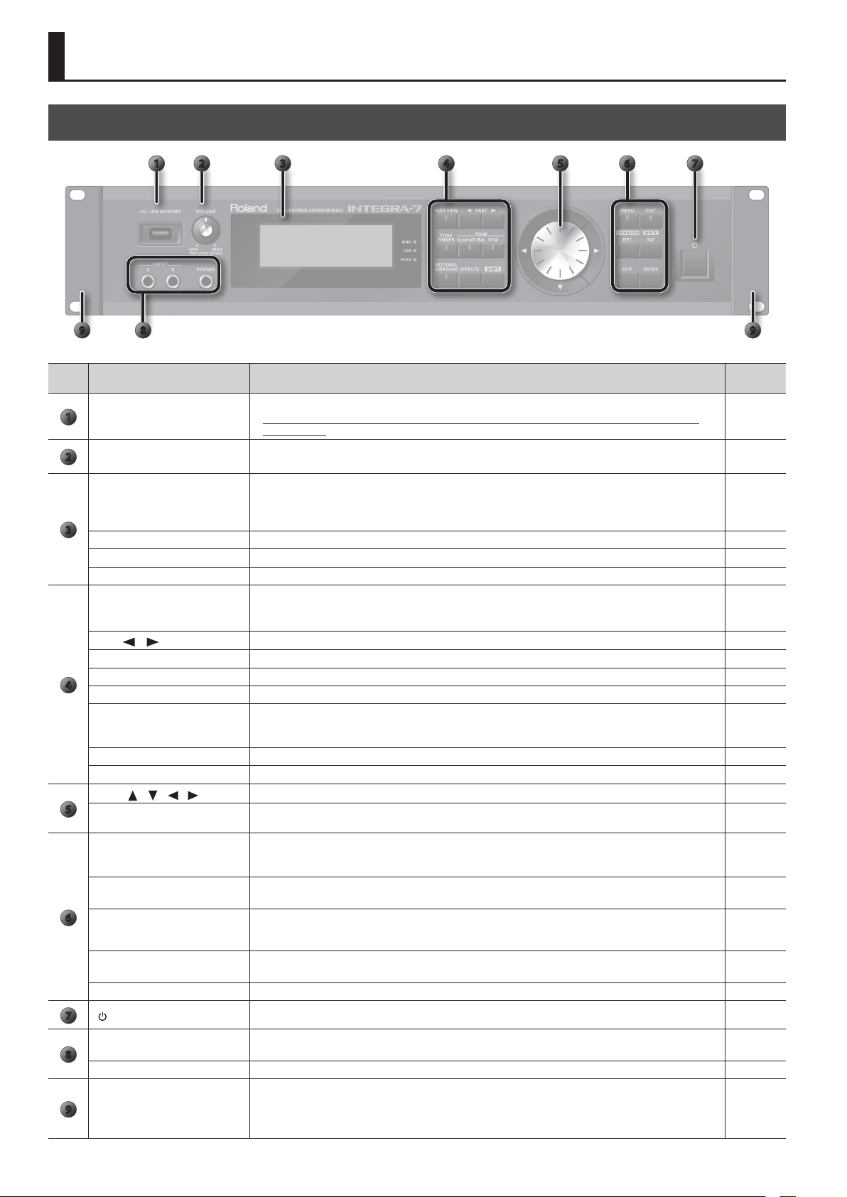
Panel Descriptions
Front Panel
1 72
3 4 5 6
89 9
Num-
Name Explanation Page
ber
USB MEMORY port
1
[VOLUME] knob
2
Display
3
MIDI indicator This will light when MIDI messages are being received from a MIDI device connected to the MIDI IN connector. –
USB indicator This will light when MIDI messages are being received from the connected computer. –
PEAK indicator This will light when the input signal from the INPUT L/R jacks reaches a level just before clipping. –
[PART VIEW] button
PART [
[TONE FINDER] button Accesses the TONE FINDER screen. p. 31
TONE [SuperNATURAL] button Changes the tone of the currently selected part to a SuperNATURAL tone, and displays the tone list. p. 31
4
TONE [PCM] button Changes the tone of the currently selected part to a PCM tone, and displays the tone list. p. 31
[MOTIONAL SURROUND] button
[EFFECTS] button Pressed to access the EFFECTS ROUTING screen. p. 36, p. 41
[SHIFT] button This is used in conjunction with other buttons to access setting screens related to those buttons. p. 29
Cursor [ ] [ ] [ ] [ ] button
5
Value dial
[MENU] button
[EDIT] button
] [ ] buttons
6
[DEC]/[INC] buttons
[EXIT] button
[ENTER] button Press this to conrm a value or execute an operation. –
7
[ ] switch
INPUT L/R jacks (front)
8
PHONES jacks You can connect headphones (sold separately) here. –
Rack-mount bracket
9
Connect USB ash drive (sold separately) here.
* Use USB Flash Memory available from Roland. Proper operation cannot be guaranteed if other USB
device is used.
Adjusts the volume of the output from the A (MIX) L/MONO, R jacks and PHONES jack.
By pressing the [VOLUME] knob you can audition the tone of the currently selected part.
Shows various information for the operation.
* The explanations in this manual include illustrations that depict what should typically be shown by the display.
Note, however, that your unit may incorporate a newer, enhanced version of the system (e.g., includes newer
sounds), so what you actually see in the display may not always match what appears in the manual.
Switches you between the screen that lists all parts, the PART VIEW screen, and the top screen.
By holding down the [SHIFT] button and pressing the [PART VIEW] button, you can access the Studio Set select
screen.
These switch the part shown in the screen. p. 28
Turns on motional surround, and displays the MOTIONAL SURROUND screen.
By holding down the [SHIFT] button and pressing the [MOTIONAL SURROUND] button, you can access the
MOTIONAL SURROUND screen without changing the motional surround on/o setting.
Move the cursor up/down/left/right. p. 28
Use this to edit values.
To make the value change rapidly, operate the value dial while holding down the [SHIFT] button.
Accesses the Menu screen.
By holding down the [SHIFT] button and pressing the [MENU] button, you can access the EXPANSION (VIRTUAL
SLOT) screen.
Displays the TONE EDIT screen for the currently selected part.
By holding down the [SHIFT] button and pressing the [EDIT] button, you can access the WRITE screen.
Use these buttons to edit values. To make the change occur more rapidly, hold down one button and press the
opposite button. You can also make the value change rapidly by holding down the [SHIFT] button and pressing
one of these buttons.
Returns you to the previous screen, or closes the window that’s currently open.
In some screens, this cancels the operation currently being executed.
Turns the INTEGRA-7 on/o. p. 21
You can connect a synthesizer or other instrument here.
If an instrument is also connected to the INPUT L/R jacks (rear), the sounds of both will be mixed.
Use these when installing the INTEGRA-7 in a 19-inch rack.
For details on how to install the INTEGRA-7 in a rack, refer to the owner’s manual included with the rack you’re
using.
* Do not remove the rack-mount brackets.
p. 50
p. 21
p. 12
p. 30
p. 34
p. 28
–
p. 38
p. 28
–
p. 47
–
20
Page 21
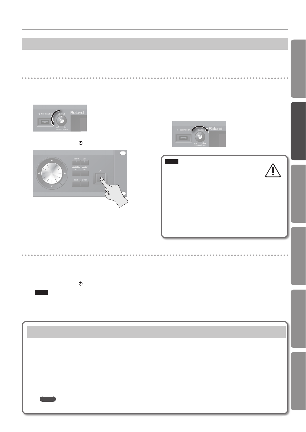
Turning the INTEGRA-7 On/O
Panel Descriptions
Once everything is properly connected (p. 22), be sure to follow the procedure below to turn on their power. If you turn on equipment in the wrong
order, you risk causing malfunction or equipment failure.
Turning the INTEGRA-7 On
Before turning the unit on/o, always be sure to turn the volume down. Even with the volume turned down, you might hear some sound when
switching the unit on/o. However, this is normal and does not indicate a malfunction.
1. Minimize the volume of the INTEGRA-7 and your speakers.
2. Turn the INTEGRA-7’s [ ] switch ON.
This unit is equipped with a protection circuit. A brief interval (a few
seconds) after turning the unit on is required before it will operate
normally.
3. Turn on the power of your speakers.
4. Use the [VOLUME] knob to adjust the volume
appropriately.
NOTE
With the factory settings, the INTEGRA-7 will
automatically be switched o four hours after you
stop playing or operating the unit. If you don’t want
the unit to turn o automatically, change the “Auto O” setting
to “OFF” as described on p. 55.
* The settings you were editing will be lost when the unit is
turned o. If you want to keep your settings, you must save your
settings before turning the unit o.
* When turning the unit back on after it was turned o by the
Auto-O function, you must wait at least 10 seconds before
turning the unit on. If you do not allow this interval to pass, the
Auto-O function might not be reset, and the unit might not
turn on normally.
Quick Guide
Introduction Playing/Creating Sounds Use with a Computer Overall Settings Appendix
Turning the INTEGRA-7 O
1. Minimize the volume of the INTEGRA-7 and your speakers.
2. Turn o the power of your speakers.
3. Turn the INTEGRA-7’s [ ] switch OFF.
NOTE
If you need to turn o the power completely, rst turn o the
unit, then unplug the power cord from the power outlet. Refer
to Power Supply (p. 5).
Playing the Demo Song
1. Press the [MENU] button.
2. Choose “DEMO PLAY” and press the [ENTER] button.
3. Choose a demo song and press the [ENTER] button.
The demo song will play.
* The performance data for the demo song will not be output from the MIDI OUT connector.
* If you want sound to be produced from the front center / subwoofer of your 5.1 channel speaker system, turn the 5.1CH Center SP Switch /
Sub Woofer(LFE) Switch “ON.”
MEMO
The DEMO MENU screen can also be accessed by pressing the [EXIT] button while holding down the [SHIFT] button.
21
Page 22

Panel Descriptions
Rear Panel Connections
AC IN jack
Connect the included AC cord here.
INPUT L/R jacks (rear)
Use audio cables to connect a synthesizer or other instrument here.
If an instrument is also connected to the INPUT L/R jacks (front), the sounds of both will be mixed.
MIDI connectors
For connecting MIDI device.
USB COMPUTER port
With a USB cable, you can connect the
INTEGRA-7 to your computer.
page 11
page 44
OUTPUT jacks
You can switch the output between
stereo, mono, and 5.1 channel surround.
For details on connections, refer to p. 23.
* Only the A (MIX) L/MONO, R jacks are balanced.
DIGITAL AUDIO OUT connector
This is a coaxial digital output connector. It complies with S/P
DIF specications. It outputs the same signal as is output from
the OUTPUT A (MIX) jacks.
It provides 44.1/48/96 kHz, 24-bit linear, stereo output.
page 23
22
Page 23

OUTPUT jacks
1: GND2: HOT
3: COLD
1: GND 2: HOT
3: COLD
(When motional surround (p. 34) is OFF)
A (MIX) L/MONO, R jacks
These jacks output a stereo signal (L/R) to your amp or mixer.
If you want to output in mono, connect to only the L side.
Both XLR type and TRS type jacks are provided; they output
the same audio.
B, C, D L/R jacks
These jacks output a stereo signal (L/R) to your amp or mixer.
* The [VOLUME] knob on the front panel does not adjust
the volume of these jacks.
8 7
Panel Descriptions
A
B
CD
D
A
221
4 36 5
C
Quick Guide
AB
INDIVIDUAL 1–8 jacks
These jacks output mono signals to your amp or mixer.
* The [VOLUME] knob on the front panel does not adjust
the volume of INDIVIDUAL 3–8 jacks.
* The output destination (A–D, 1–8) can be assigned
independently for each part “Output Assign” (p. 32).
OUTPUT jacks
(When motional surround (p. 34) is ON)
Supports both two-channel and 5.1 channel surround output.
MOTIONAL SURROUND 2 CH L/R jacks
These jacks allow two speakers to output sound with spatial
depth as specied by the motional surround settings.
The same audio will be output from the TRS type and the XLR
type jacks.
MOTIONAL SURROUND 5.1 CH L/R/C/Ls/Rs/LFE jacks
These jacks output 5.1 channel surround as specied by the
motional surround settings.
Position your speakers as shown in the illustration.
* The [VOLUME] knob on the front panel does not adjust
the volume of these jacks.
LFE
Rs
Ls
Introduction Playing/Creating Sounds Use with a Computer Overall Settings Appendix
1
R L
L R
Motional
Surround
R L
RRL
C
LFE
L
Ls
C
Rs
* Two-channel and 5.1 channel surround are output simultaneously.
* To prevent malfunction and equipment failure, always turn down the volume, and turn o all the units before making any connections.
* This instrument is equipped with balanced (XLR/TRS) type jacks. Wiring diagrams for these jacks are shown below. Make connections after rst
checking the wiring diagrams of other equipment you intend to connect.
TIP: HOT
RING: COLD
SLEEVE: GND
* When connection cables with resistors are used, the volume level of equipment connected to the input jacks (front, rear) may be low. If this
happens, use connection cables that do not contain resistors.
1: GND 2: HOT
3: COLD
23
Page 24

Getting Acquainted with the INTEGRA-7
Studio Sets
Studio Sets allow you to use multiple tones and drum kits simultaneously.
One studio set contains 16 “parts” for tones and one external part (EXT PART). You can assign a tone or drum kit to each part, allowing you to create an
ensemble or to play rich-sounding layers.
If you’re using an external MIDI device or DAW software, you’ll be able to independently control multiple sounds on a single INTEGRA-7 unit.
How a Tone Is Structured
A “tone” is a unit of sound used when performing. There are “SuperNATURAL tones” and
“PCM tones,” each containing their own eect (MFX) settings.
You need to select a tone from the sound library and assign it to a part. You can also
edit a tone and save it in user memory.
SuperNATURAL Tone
There are three types of SuperNATURAL tones:
“SuperNATURAL acoustic tones,” “SuperNATURAL synth
tones,” and “SuperNATURAL drum kits.”
SuperNATURAL Acoustic Tone (p. 38)
These tones do not merely reproduce the sound of
acoustic instruments, they also use behavior modeling
technology appropriate for the selected tone to
emulate the expressive power distinctive of each
acoustic instrument, such as the phrases performed
by the player and the dierences between chords and
melodic phrases.
SuperNATURAL Synth Tone (p. 38)
These tones consist of three partials, and allow powerful
synth sounds to be produced by a single tone.
SuperNATURAL Drum Kit (p. 39)
These tones consist of 62 partials; they allow you to
sound a dierent percussion instrument for each key
(note number) that’s played.
A drum kit is provided with six compressor + equalizer
units, allowing you to divide the instruments into
groups so that you can individually adjust the dynamics
of each group or modify its tone quality.
SOUND LIBRARY
TONE
PCM
EXPANSION (VIRTUAL SLOT)
EXPANSION SOUNDS
PCM Tone
There are two types of PCM tones: “PCM synth tones”
and “PCM drum kits.”
PCM Synth Tone (p. 39)
These tones consist of four partials. Each partial can
be turned on/o individually, allowing you to choose
which partials will be heard.
SLOT
A
USB AUDIO
or
INPUT (Front/Rear)
ACOUSTIC SYNTH
SYNTH
SLOT
B
LOAD
ExPCM
SLOT
C
ExSN4ExSN1 ExSN5ExSN2 ExSN6ExSN3
DRUM KIT
DRUM KIT
SLOT
D
PCM Drum Kit (p. 40)
These consist of 88 partials, and allow for the play of a dierent percussion instrument sound for each key (note number) you press. A drum kit is
provided with six compressor + equalizer units, allowing you to divide the instruments into groups so that you can individually adjust the dynamics
of each group or modify its tone quality.
* The six compressor + equalizer units for a drum kit are applied only to one specied part of the multiple parts to which a drum kit can be assigned.
Make this setting in STUDIO SET COMMON (p. 32).
* Dedicated multi-eect settings are included in each tone (SuperNATURAL tones and PCM tones) built into the INTEGRA-7.
EXPANSION Virtual Slots
EXPANSION Virtual Slots are banks into which you can load “EXPANSION SOUNDS” sound data for use.
“SRX tones,” “SuperNATURAL tones,” or “ExPCM (GM2 compatible) tones” can be loaded into an EXPANSION Virtual Slot. “ExPCM tones” use all
four slots, meaning that they do not allow other tones to be loaded.
For details, refer to “04 Using the Expansion Sounds” (p. 14).
24
Page 25

How a Studio Set Is Structured
Getting Acquainted with the INTEGRA-7
A studio set has sixteen parts; you can assign a tone to each part, allowing you to use sixteen sounds simultaneously.
STUDIO SET
PART 16
PART 15
PART 14
ASSIGN
ASSIGN
EXT PART
PART 3
PART 2
PART 1
TONE
INST/PARTIAL
PART 10 (DRUM PART)
DRUM KIT
DRUM INST
62
DRUM INST
01
DRUM
INST
OUTPUT
ASSIGN
MFX
MFX
EQ
EQ
LEVEL
LEVEL
LEVEL
MOTIONAL
SURROUND
ON/OFF
ON
OFF
MOTIONAL SURROUND
REVERB
CHORUS
Quick Guide
Introduction Playing/Creating Sounds Use with a Computer Overall Settings Appendix
MASTER
COMP+EQ 6
COMP+EQ 5
COMP+EQ 4
COMP+EQ 3
COMP+EQ 2
COMP+EQ 1
* Although you are free to assign a drum kit to any or all of the parts, we have assigned a drum kit to part 10 and a tone to the
remaining parts as an example.
DRUM
COMP+EQ
OUTPUT
ASSIGN
EQ
2 CH/MIX OUT
5.1 CH/INDIVIDUAL OUT
Bank
Tones are organized into groups called “banks.”
Part
A “part” is a location to which you can assign a tone or drum kit in order to play it on the INTEGRA-7.
Partial
A “partial” is a unit of sound within a SuperNATURAL synth tone (p. 38), SuperNATURAL drum kit (p. 39), PCM synth tone (p. 39), or PCM drum kit (p. 40).
These tones consist of multiple partials.
Inst
An “inst” is the smallest unit of sound within a SuperNATURAL acoustic tone (p. 38). Each SuperNATURAL acoustic tone consists of a single “inst.”
25
Page 26

Getting Acquainted with the INTEGRA-7
Eects
The INTEGRA-7 contains the following eects; each eect can be edited independently.
STUDIO SET
PART 1–9, 11–16
TONE
INST/PARTIAL
PART 10 (DRUM PART)
MFX
DRUM KIT
DRUM INST 1–62
COMP+EQ
1–6
MFX
Eects for a Tone
Multi-eects (MFX)
These are general-purpose eects that can modify the sound itself,
even transforming it into an entirely dierent type of sound.
You can choose from 67 types of eects as appropriate for your
purpose.
There are types that consist of a single eect, such as distortion or
anger, as well as a wide variety of other types. Although the multieect types also include chorus, this is a separate processor that is
independent of the chorus unit of a studio set.
Each tone has one set of multi-eect settings.
Compressor + Equalizer (COMP + EQ)
A drum part allows you to use six compressor + equalizer units.
They can be assigned individually to the drum instruments.
* Although it is possible to assign drum kits to all of the parts, the
six compressor + equalizer sets provided for a drum kit will be
available only for the single part you specify (the Drum COMP +
EQ Assign part).
DRUM COMP+EQ
OUTPUT ASSIGN
MOTIONAL SURROUND
EQ
EQ
MOTIONAL
SURROUND
ON/OFF
ON
OFF
Eects for a Studio Set
Equalizer (EQ)
This equalizer is applied to each individual part.
It allows you to independently adjust the high, mid, and lowfrequency ranges.
MOTIONAL SURROUND
Motional surround allows you to not only position a sound
anywhere between the left and right edges of the sound eld, but
also allows you to move it towards the front or rear.
Two-channel and 5.1 channel output is supported, allowing you to
place each instrument at the desired depth.
* When you turn Motional Surround on, reverb/chorus will not be
applied.
CHORUS
The chorus eect adds depth and spaciousness to the sound.
* Motional Surround and chorus cannot be applied at the same time.
2 CH/
MIX OUT
MASTER
EQ
REVERB
CHORUS
5.1 CH/
INDIVIDUAL
OUT
26
REVERB
The reverb eect adds the reverberation that is characteristic of
sounds played in a concert hall.
You can choose from six types of reverb as appropriate for your
needs.
* Motional Surround and reverb cannot be applied at the same time.
MASTER EQ
This equalizer is applied to the overall sound of the entire
INTEGRA-7 sound module.
It allows you to independently adjust the high, mid, and lowfrequency ranges.
Page 27

Getting Acquainted with the INTEGRA-7
About Memory
Memory is where data such as the settings for studio sets and tones are held.
There are three types of memory: “temporary memory” (the temporary area, and the EXPANSION Virtual Slots), “rewritable memory” (user memory,
system memory, and USB memory), and “non-rewritable memory” (preset memory).
INTEGRA-7
Quick Guide
EXPANSION Virtual Slot
Load Select Select Write
Preset Memory
SuperNATURAL Acoustic Tone
SuperNATURAL Synth Tone
SuperNATURAL Drum Kit
PCM Synth Tone
PCM Drum Kit
EXPANSION SOUNDS
Temporary Area
User Memory System Memory
Studio Set
SuperNATURAL Acoustic Tone
SuperNATURAL Synth Tone
SuperNATURAL Drum Kit
PCM Synth Tone
PCM Drum Kit
Backup ExportRestore
Import
USB Memory
ROLAND Folder
SOUND FolderBACKUP Folder
Backup Sound Data
System
Setting
Introduction Playing/Creating Sounds Use with a Computer Overall Settings Appendix
Temporary memory
Temporary Area
This area temporarily holds the data of
the studio set or tone that you’ve selected
from the panel.
When you play, the INTEGRA-7 produces
sound according to the settings in the
temporary area. When you edit a studio
set or a tone, you’re not directly modifying
the data in that memory; rather, the data
is called into the temporary area, and your
editing modies this data.
Settings in the temporary area are
temporary, and will be lost when you turn
o the unit or call up other settings. If you
want to keep the settings of the temporary
area, you must execute the Write operation
(p. 29) to save them into rewritable User
Memory.
EXPANSION Virtual Slots
Sound data from EXPANSION SOUNDS can
be loaded into these memory locations to
expand the available sounds.
You can load four titles of SRX or
SuperNATURAL sound data into these
virtual slots.
Rewritable memory
System Memory
This is memory that holds the system
parameter settings that specify how the
INTEGRA-7 is to operate. To store the
system parameters, execute the System
Write operation (p. 48).
User Memory
This is memory that stores data inside the
INTEGRA-7. To store a studio set, execute
Studio Set Write (p. 34). To store a tone,
execute Tone Write (p. 40). To store a drum
kit, execute Drum Kit Write (p. 40).
* EXPANSION SOUNDS sound data
that you’ve edited in the temporary
area can be saved in user memory,
but it will not be audible unless the
EXPANSION SOUNDS used by that
sound data have been loaded into an
EXPANSION Virtual Slot.
USB Memory
You can use a USB ash drive to back up
all of the studio sets, tones, and drum kits
in User Memory, together with the system
parameters from System Memory, as a
single collection of data (p. 52).
Of the studio sets and tones saved in the
INTEGRA-7, you can select the desired
sound data and export it to a USB ash
drive. You can also select a desired studio
set or tone from a le that was previously
exported to a USB ash drive, and import
it.
Non-rewritable Memory
Preset Memory
The data in preset memory cannot be
rewritten.
However, settings loaded from preset
memory into the temporary area can be
edited and then stored in user memory.
27
Page 28

Basic Operation
This section explains the basic button operations used to operate the INTEGRA-7.
[TONE FINDER] button
Accesses the TONE FINDER screen.
page 31 page 30 page 15
TONE [SuperNATURAL] button
TONE [PCM] button
These switch the tone of the
currently selected part between
SuperNATURAL or PCM tones, and
display a tone list.
page 31
[PART VIEW] button
Accesses the screen that lists all parts.
Press this button once again to access
the PART VIEW screen for the currently
selected part.
[SHIFT] + [PART VIEW] button
Accesses the Studio Set select
screen.
[MOTIONAL SURROUND] button
Accesses the MOTIONAL SURROUND
screen.
page 34
[MENU] button
Accesses the menu screen.
Accesses settings for the INTEGRA-7
or various functions.
[SHIFT] + [MENU] button
Accesses the data loading screen
for the EXPANSION Virtual Slots.
[EFFECTS] button
Accesses the EFFECTS ROUTING
screen.
page 36
page 41 page 28
[EDIT] button
Accesses the TONE EDIT screen
for the currently
selected part.
[SHIFT] + [EDIT] button
Accesses the WRITE screen.
Cursor buttons
Move the cursor.
Value dial
Edits a value.
page 38
page 29
page 28
Switching Parts
Here’s how to switch the part that’s shown in the screen or is
selected (the “current part”).
In the top screen, the current part is indicated by a
the part number.
PART [ ] [ ] buttons
Press the PART [ ] button to switch to the next part. Press the
PART [
If you hold down the PART [
change successively.
The part will switch more rapidly if you press the PART [
PART [ ] button) while holding down the PART [ ] button (or
PART [ ] button).
] button to switch to the previous part.
] or PART [ ] button, the part will
Moving the Cursor
A single screen or window will contain multiple items (parameters)
to edit or select. To edit a parameter’s setting, you must rst move
the cursor to that parameter’s value.
The value of the selected parameter is highlighted.
Cursor buttons
symbol below
] (or
Editing a Value
To edit the value highlighted by the cursor, use either of the
following controllers.
• Value dial
• [DEC] [INC] button
Value dial
Turning the value dial toward the right will increase the value, and
turning it toward the left will decrease the value.
If you hold down the [SHIFT] button while turning the value dial,
the value will change in larger steps.
[DEC] [INC] buttons
Press the [INC] button to increase the value, or press the [DEC]
button to decrease the value.
• If you hold down a button, the value will increase (or decrease)
continuously.
• To rapidly increase the value, hold down the [INC] button and
press the [DEC] button. Conversely, to rapidly decrease the
value, hold down the [DEC] button and press the [INC] button.
• If you hold down the [SHIFT] button and press the [INC] button
or [DEC] button, the value will change in larger steps.
You can move the cursor by pressing the cursor [ ] [ ] [ ] [ ]
buttons.
If you hold down a cursor button, the cursor will continue moving.
If you hold down the cursor button for the desired direction, and
then press the opposite cursor button, the cursor will move more
quickly.
28
Page 29

Basic Operation
[SHIFT] Button Operations
By holding down the [SHIFT] button and pressing another button,
you can edit the settings of the button you pressed, or access a
specic screen (shortcut).
If you hold down the [SHIFT] button while editing a parameter’s
value, the value will change in larger steps.
Shortcut list
Shortcut Explanation
[SHIFT] + [PART VIEW] Accesses the Studio Set select screen.
[SHIFT] + PART [
[SHIFT] + PART [
[SHIFT] + cursor [
[SHIFT] + cursor [
[SHIFT] +
[MOTIONAL SURROUND]
[SHIFT] + [MENU] Accesses the Expansion Load screen.
[SHIFT] + [EDIT]
[SHIFT] + [ENTER]
[SHIFT] + [EXIT] Accesses the DEMO MENU screen.
[EXIT] + [
[MENU] + [
[SHIFT] +
press the [VOLUME]
]
]
]
]
] (startup)
] (startup)
Select the part 1.
Select the Ext part.
Switch between tabs in screens that
contain tabs.
Accesses the Motional Surround setting
screen without changing the MOTIONAL
SURROUND ON/OFF status.
Accesses the corresponding WRITE MENU
screen for each page.
Switches the display type in the top
screen..
Starts up the INTEGRA-7 without loading
the expansions.
* Continue holding down [EXIT] button
until the top screen appears.
Returns the LCD contrast and LCD
backlight brightness to their factory
settings, and accesses the LCD contrast
setting screen.
* Continue holding down [MENU] button
until the setup screen appears.
Continues preview playback. Press the
[VOLUME] knob once again to stop.
Saving
From the top screen, hold down the [SHIFT] button and press the
[EDIT] button to access the WRITE MENU screen. Select a studio set
or tone, and save your settings.
From the TONE EDIT screen, hold down the [SHIFT] button and
press the [EDIT] button to save the tone.
From the SYSTEM screen, hold down the [SHIFT] button and press
the [EDIT] button to save the system settings.
Studio Set
Save the Studio Set.
Tone/Drum Kit
Save the Tone/Drum Kit
System
Save overall settings for the INTEGRA-7.
page 34
page 40
page 48
Assigning a Name
The INTEGRA-7 lets you assign names to the following items.
• Studio Set
• Tone/Drum Kit
• Sound data to be exported
• Backup le
Regardless of what you’re naming, the procedure is the same.
1. Press the [ ] [ ] buttons to move the cursor to the
location where you wish to input a character.
2. Turn the VALUE dial, or press the [DEC] [INC] buttons to
specify the character.
You can use the cursor [ ] [ ] buttons to switch between
uppercase and lowercase letters.
Quick Guide
Introduction Playing/Creating Sounds Use with a Computer Overall Settings Appendix
[ENTER] Button Operations
The [ENTER] button is used to set a value or to execute an
operation.
In the various editing screens, pressing the [ENTER] button will
display a parameter list. Select a value and then press the [ENTER]
button once again to conrm your selection.
3. If you decide to cancel your input, press the [EXIT] button.
Inserting or Deleting Characters
When entering a name, you can insert or delete characters.
1. While entering a name, press the [MENU] button.
The Menu screen will appear.
Pressing the [MENU] button once again will take you back to the
previous screen.
2. Choose “INSERT” or “DELETE,” and press the [ENTER]
button.
Function Explanation
INSERT
DELETE
Press the [ENTER] button to insert a space (blank) at the
cursor location.
Press the [ENTER] button to delete the character at the cursor
location; subsequent characters will be moved forward to ll
the gap.
29
Page 30

Playing Sounds
Choosing a Studio Set
A Studio Set stores the sounds selected for each Part, as well
as various performance-related settings (except for system
parameters).
By switching studio sets you can change sounds at the beginning of
a song or change large numbers of settings at once.
NOTE
If you’re selecting a studio set that uses tones from an
EXPANSION Virtual Slot, you won’t hear anything unless the
corresponding sound data is loaded.
1. Press the [MENU] button.
2. Choose “STUDIO SET SELECT” and press the[ENTER]
button.
3. Use the value dial to select a Studio Set.
4. Press the [ENTER] button.
The studio set will be switched.
Viewing the Part Settings (PART VIEW Screen)
In this screen you can edit the part parameters while focusing on a
single part.
1. In the top screen, press the [PART VIEW] button twice.
2. Use the PART [ ] [ ] buttons to select the part that
you want to change.
3. Use the cursor buttons to select the item that you want to
edit, and use the value dial to edit the value.
Temporarily Silencing a Part’s Sound (MUTE)
Here’s how to temporarily mute (silence) the sound of each part.
MEMO
You can also access the STUDIO SET selection screen by holding
down the [SHIFT] button and pressing the [PART VIEW] button.
Viewing a List of All Parts (PART VIEW -ALL- Screen)
In this screen you can edit the part parameters while viewing a list
of all parts.
* Some of the part parameters are not shown.
1. Press the [PART VIEW] button.
2. Use the cursor buttons to select the item that you want to
edit, and use the value dial to edit the value.
By holding down the [SHIFT] button and pressing a cursor [ ] [ ]
button you can switch between tabs.
1. In the top screen, move the cursor to “MUTE.”
2. Use the PART [ ] [ ] buttons to select the part that
you want to mute (silence).
3. Use the [DEC] [INC] buttons to turn mute on/o.
The bar (—) above the part number will disappear to
indicate parts for which Mute is turned on.
Listening to Only One Part (SOLO)
Here’s how you can listen to only the sound of the currently
selected part.
1. In the top screen, move the cursor to “SOLO.”
30
Only the selected part will be heard.
2. Use the PART [ ] [ ] buttons to select the part that
you want to hear.
3. Use the [DEC] [INC] buttons to turn solo on/o.
MEMO
If you switch parts while solo is on, the soloed part will also
change.
Page 31

Playing Sounds
Choosing a Tone
In the PART VIEW screen you can select the tone for each part.
You can view the tone list by category or by type.
Tone Preview function
By pressing the [VOLUME] knob you can audition the tone of the
selected part.
Selecting Tones from a Tone List by Category
1. Press the [TONE FINDER] button.
The tone list organized by category will appear.
2. Use the cursor [ ] [ ] buttons to switch categories.
3. Use the value dial or the cursor [ ] [ ] buttons to select
a tone, and press the [ENTER] button.
Selecting Drum Kits from a Tone List
1. Press the [SuperNATURAL] or [PCM] button.
The tone list will appear.
2. Use the cursor buttons to select the drum kit tab.
Select the “SN Drum Kit” tab for SuperNATURAL tones, or the “PCM
Drum Kit” tab for PCM tones.
3. Use the value dial or the cursor [ ] [ ] buttons to select
a drum kit, and press the [ENTER] button.
Quick Guide
Introduction Playing/Creating Sounds Use with a Computer Overall Settings Appendix
MEMO
By holding down the [SHIFT] button and using the cursor
[
] [ ] buttons, you can switch to the next (or previous)
type/bank.
Selecting Tones from a Tone List by Type/Bank
1. Press the [SuperNATURAL] or [PCM] button.
The tone list will appear.
2. Use the cursor buttons to switch the type or bank tab.
3. Use the value dial or the cursor [ ] [ ] buttons to select
a tone, and press the [ENTER] button.
31
Page 32

Editing a Studio Set
Studio Set Common Settings
Here you can make settings that are common to the entire studio
set.
1. In the Top screen, press the [MENU] button.
2. Choose “STUDIO SET COMMON” and press the [ENTER]
button.
3. Use the cursor buttons to select an item, and use the
value dial to edit the value of that item.
COMMON parameter
MEMO
For details on the part parameters, refer to “Parameter Guide
PDF.”
Tab Explanation
GENERAL
CONTROL
PHASE
LOCK
Species the tempo of the studio set, and the drum part to
which COMP+EQ will be applied.
When using tone controls 1–4, species the MIDI messages
that will control the parameters.
Turn this “on” if you want to minimize discrepancies in timing
between notes played by parts on the same MIDI channel.
Editing the Part Settings
A studio set contains 16 parts; you can edit settings such as volume
(Level), equalizer (EQ), and key range (KBD) for each part.
1. In the top screen, press the [PART VIEW] button twice.
2. Use the cursor buttons to select the item that you want to
edit, and use the value dial to edit the value.
By holding down the [SHIFT] button and pressing a cursor [ ] [ ]
button you can switch between tabs.
MEMO
For details on the part parameters, refer to “Parameter Guide
PDF.”
Parts 1–16
Tab Parameter Value
TYPE Displays/selects the tone type.
TONE
BANK Displays/selects the tone bank.
Tone Number
Displays/selects the tone number.
The tone name is shown at the right.
Tab Parameter Value
Adjust the volume of each part.
This setting’s main purpose is to adjust the volume
balance between parts.
Adjust the pan of each part.
“L64” is far left, “0” is center, and “63R” is far right.
* This has no eect if Motional Surround is on.
Sets the level of the signal sent to chorus for each
part.
Set this to 0 if you don’t want to apply chorus.
Sets the level of the signal sent to reverb for each
part.
Set this to 0 if you don’t want to apply reverb.
Species for each part how the direct sound will be
output.
If Motional Surround is on, surround output will be
enabled, and this setting will be ignored.
For each part, specify whether it will receive MIDI
data (ON) or ignore it (OFF).
Sets how the Patch’s notes play. The MONO setting is
eective when playing a solo instrument Patch such
as sax or ute.
Turn this parameter “ON” when you want to use the
Legato feature and “OFF” when you don’t.
Legato is a feature that works only when the Mono/
Poly is MONO. When Legato is ON, pressing one key
when another is already pressed causes the currently
playing note’s pitch to change to that of the newly
pressed key while continuing to sound. This can be
eective when you wish to simulate performance
techniques such as a guitarist’s hammering on and
pulling o strings.
* This setting is ignored for parts to which a tone is
assigned.
Species the number of voices that reserved for
each Part when more than 128 voices are played
simultaneously.
Turn this “
or “– (OFF)” if you don’t.
Species the width of the mid range.
Higher values make the range narrower.
This determines what will happen to the tone’s level
when a note that’s higher than the tone’s specied
keyboard range is played.
Higher settings produce a more gradual decrease
in volume. If you don’t want the tone to sound at all
when a note outside the keyboard range is played,
set this parameter to “0.”
Species the highest note that the tone will sound
for each tone.
* If you attempt to raise the lower key higher than
the upper key, or to lower the upper key below the
lower key, the other value will be automatically
modied to the same setting.
Species the lowest note that the tone will sound for
each tone.
This determines what will happen to the tone’s level
when a note that’s lower than the tone’s specied
keyboard range is played.
Higher settings produce a more gradual decrease
in volume. If you don’t want the tone to sound at all
when a note outside the keyboard range is played,
set this parameter to “0.”
LEVEL
EQ
KBD
Level
Pan
Cho Send Level
Rev Send Level
Output Assign
Rx Switch
Rx Channel Species the MIDI channel of each part.
Mono/Poly
(*)
Legato Switch
(*)
Voice Reserve
(*)
EQ Switch
EQ Low Freq (*) Species the frequency of the low range.
EQ Low Gain Species the amount of boost/cut for the low range.
EQ Mid Freq (*) Species the frequency of the mid range.
EQ Mid Gain Species the amount of boost/cut for the mid range.
Q (*)
EQ High Freq(*) Species the frequency of the high range.
EQ High Gain Species the amount of boost/cut for the high range.
Key Fade Upper
Key Range
Upper
Key Range
Lower
Key Fade Lower
(ON)” if you want to use the equalizer,
32
Page 33

Editing a Studio Set
Tab Parameter Value
This determines what will happen to the tone’s level
when the tone is played at a velocity greater than its
specied velocity range.
Higher settings produce a more gradual decrease in
volume.
If you want notes played outside the specied key
velocity range to not be sounded at all, set this to “0.”
This species the upper limit of the velocities that will
sound the tone.
Edit this setting if you want to use velocity to switch
between tones.
* If you attempt to set the Lower velocity limit above
the Upper, or the Upper below the Lower, the other
value will automatically be adjusted to the same
setting.
This species the lower limit of the velocities that will
sound the tone.
Edit this setting if you want to use velocity to switch
between tones.
This determines what will happen to the tone’s level
when the tone is played at a velocity lower than its
specied velocity range.
Higher settings produce a more gradual decrease in
volume.
If you want notes played outside the specied key
velocity range to not be sounded at all, set this to “0.”
Applies an oset to the velocity sensitivity for the
entire tone, while preserving the dierences between
velocity sensitivity values.
Adjusts the pitch of the part’s sound up or down in
units of an octave (over a range of +/-3 octaves).
Adjusts the pitch of the part’s sound up or down in
semitone steps (over a range of +/-4 octaves).
Adjusts the pitch of the part’s sound up or down in
1-cent steps (over a range of +/-50 cents).
Species the amount of pitch change in semitones
(over a range of 2 octaves) that will occur when the
Pitch Bend Lever is moved. The amount of change
when the lever is tilted is set to the same value for
both left and right sides.
Species whether the portamento eect will be
applied (ON) or not (OFF).
* Portamento is an eect which smoothly
changes the pitch from the rst-played key to the
next-played key. By applying portamento when the
Mono/Poly parameter is “MONO,” you can simulate
slide performance techniques on a violin or similar
instrument.
When portamento is used, this species the time
over which the pitch will change. Higher settings
will cause the pitch change to the next note to take
more time.
Adjusts the cuto frequency for the tone or drum kit
assigned to a part.
Adjusts the Resonance for the tone or drum kit set
assigned to a part.
Adjusts the Attack Time for the tone or drum kit
assigned to a part.
Adjusts the Decay Time for the tone or drum kit
assigned to a part.
Adjusts the Release Time for the tone or drum kit
assigned to a part.
For each part, adjust the vibrato speed (the rate
at which the pitch is modulated). The pitch will be
modulated more rapidly for higher settings, and
more slowly with lower settings.
For each part, this adjusts the depth of the vibrato
eect (the depth at which the pitch is modulated).
The pitch will be modulated more greatly for higher
settings, and less with lower settings.
KBD
PITCH
OFFSET
Velo Fade
Upper (*)
Velo Range
Upper (*)
Velo Range
Lower (*)
Velo Fade
Lower (*)
Velo Sens
Oset (*)
Octave Shift
Coarse Tune
Fine Tune
Bend Range
Porta Switch (*)
Porta Time (*)
Cuto Oset
Reso Oset
Attack Oset
Decay Oset
Release Oset
Vibrato Rate (*)
Vibrato Depth
(*)
Tab Parameter Value
For each part, this adjusts the time delay until the
vibrato (pitch modulation) eect begins. Higher settings will produce a longer delay time before vibrato
begins, while lower settings produce a shorter time.
If you want to play the keyboard using a tuning
other than equal temperament, you can choose an
alternative tuning such as just intonation (major,
minor) or an Arabian scale.
When using a tuning other than equal temperament,
choose the tonic that’s appropriate for the key of the
song you’re playing (i.e., the note corresponding to
“C” for major, or “A” for minor).
If you’re using equal temperament, there’s no need to
select the tonic.
For each note, this lets you adjust the pitch in
steps of one cent (1/100 semitone) relative to the
equal-tempered pitch.
Species whether Program Change messages will be
received (ON) or not (OFF).
Species whether Bank Select messages will be
received (ON) or not (OFF).
Specify whether Pitch Bend messages will be
received (ON), or not (OFF).
Specify whether Polyphonic Key Pressure messages
will be received (ON), or not (OFF).
Specify whether Channel Pressure messages will be
received (ON), or not (OFF).
Specify whether Modulation messages will be
received (ON), or not (OFF).
Specify whether Volume messages will be received
(ON), or not (OFF).
Specify whether Pan messages will be received (ON),
or not (OFF).
Specify whether Expression messages will be
received (ON), or not (OFF).
Specify whether Hold 1 messages will be received
(ON), or not (OFF).
Velocity Curve selects for each MIDI channel one
of the four Velocity Curve types that best matches
the touch of the connected MIDI keyboard. Set this
to “OFF” if you are using the MIDI keyboard’s own
velocity curve.
OFFSET
SCALE
MIDI
Vibrato Delay
(*)
Type
Key
(Keyboard)
(*)
PC (Rx Program
Change)
BS (Rx Bank
Select)
BEND (Rx Pitch
Bend)
PAFT (Rx Poly
Key Press)
CAFT (Rx Ch
Press)
MOD (Rx
Modulation)
VOL (Rx
Volume)
PAN (Rx Pan)
EXP (Rx
Expression)
HOLD (Rx
Hold-1)
VELO CRV (Velo
Crv Type)
(*): Not shown in the PART VIEW -ALL- screen.
* Depending on the sound, some of the part parameters will have
no eect.
Ext part
Parameter Explanation
Level
Cho Send Level
Rev Send Level
Species the volume of the part.
This is used mainly to adjust the volume balance
between parts.
Species the depth of chorus.
Set this to 0 if you don’t want to apply chorus.
Species the depth of reverb.
Set this to 0 if you don’t want to apply reverb.
Quick Guide
Introduction Playing/Creating Sounds Use with a Computer Overall Settings Appendix
33
Page 34

Editing a Studio Set
Saving a Studio Set
Edits you make to a Studio Set are temporary; they will be lost
when you turn o the unit or select another Studio Set. If you want
to keep an edited Studio Set, you must save it.
NOTE
When you execute the Write operation, the existing data at the
write destination will be overwritten.
1. From the top screen or the STUDIO SET EDIT screen, hold
down the [SHIFT] button and press the [EDIT] button.
The WRITE MENU screen will appear.
2. Choose “STUDIO SET WRITE” and press the [ENTER]
button.
3. Assign a name for the Studio Set.
For details on how to assign a name, refer to “Assigning a Name” (p.
29).
4. Press the [ENTER] button.
5. Use the value dial or the [DEC] [INC] buttons to select the
desired save destination.
6. Press the [ENTER] button.
A message will ask “Are you sure?”
7. To execute, choose “OK” and press the [ENTER] button.
MEMO
If you decide to cancel without saving, press the [EXIT] button.
NOTE
Never turn o the unit while settings are being saved.
Panning the Sound with Depth (MOTIONAL SURROUND Screen)
In addition to the left/right panning of each sound, the INTEGRA-7
lets you specify its depth in the sound eld.
In the MOTIONAL SURROUND screen you can visually specify the
left/right panning and depth of each sound.
1. Press the [MOTIONAL SURROUND] button.
Motional Surround will turn on, and the MOTIONAL SURROUND
screen will appear.
2. Use the cursor buttons to specify the position (left/right
and depth) of each instrument.
You can use the PART [ ] [ ] buttons to switch the part you’re
editing.
MEMO
• If you want to turn Motional Surround o, press the [MOTIONAL
SURROUND] button once again in the Motional Surround
screen.
• If you want to return to the previous screen but leave Motional
Surround turned on, press the [EXIT] button.
• The [MOTIONAL SURROUND] button’s indicator shows whether
Motional Surround is on (lit) or o (unlit).
• By holding down the [SHIFT] button and pressing the
[MOTIONAL SURROUND] button, you can access the Motional
Surround screen without changing the Motional Surround on/
o setting.
* Motional Surround and reverb/chorus cannot be applied at the
same time.
* When you turn Motional Surround on, reverb/chorus will turn
o.
34
Page 35

Editing a Studio Set
Editing the Motional Surround Settings
Here’s how to turn Motional Surround on/o and specify the size of
the room.
1. In the MOTIONAL SURROUND screen, press the [ENTER]
button.
MOTIONAL SURROUND EDIT screen will appear.
2. Use the cursor buttons to select the item you want to edit,
and use the value dial to edit the value.
You can use the cursor [ ] [ ] buttons to switch tabs.
Tab Parameter Explanation
These are overall settings for Motional Surround.
Room Type Species the room type.
Room Size Species the room size.
COMMON
PART
CONTROL
Motional
Surround Depth
Ambience Level Species the volume of ambience.
Ambience Time Species the duration of ambience.
Ambience
Density
Ambience HF
Damp
These numerically specify the position of each part’s
instrument.
You can also use MIDI control changes to control the values
of these parameters (except for Width).
L-R
F-B
Width
Ambience Send
Level
Ext Part Control
Ch
Species the depth of the Motional
Surround eect.
Species the density of ambience.
Species the frequency at which the high
range of the ambience will be cut.
Species the left/right position.
Control change number
• 1–16 Part : CC12
• Ext Part : CC28
Species the front/rear (back) position.
Control change number
• 1–16 Part : CC13
• Ext Part : CC29
Species the width of the positioned
sound.
Species the send level to ambience
Control change number
• 1–16 Part : CC14
• Ext Part : CC30
Species the MIDI channel used when
controlling the front/back/left/right
position and ambience send level of an
Ext part via MIDI.
Turning Eects On/O
Quick Guide
1. In the top screen, press the [EFFECTS] button.
The EFFECTS ROUTING screen will appear.
When Motional Surround is “o”
Introduction Playing/Creating Sounds Use with a Computer Overall Settings Appendix
When Motional Surround is “on”
2. Use the cursor buttons to select the eect that you want
to turn on/o.
3. Use [DEC] [INC] button to turn each eect on/o.
MEMO
For details on the parameters, refer to “Parameter Guide PDF.”
35
Page 36

Editing a Studio Set
Editing the Eects of a Studio Set
(EFFECTS ROUTING Screen)
Here’s how to edit a studio set’s eects.
1. In the top screen, press the [EFFECTS] button.
The EFFECTS ROUTING screen will appear.
When Motional Surround is “o”
When Motional Surround is “on”
2. Move the cursor to the eect that you want to edit, and
press the [ENTER] button.
3. Use the cursor buttons to select the setting you want to
edit, and use the value dial to edit its value.
Editing the REVERB Settings
To edit Reverb settings, access the Reverb parameter screen.
* Reverb will not be available when Motional Surround is on.
1. Access the EFFECTS SWITCH screen or the EFFECTS
ROUTING screen when the Motional Surround function is
“OFF,” move the cursor to “REVERB,” and press the [ENTER]
button.
2. Use the cursor buttons to select the setting that you want
to edit, and use the value dial to edit its value.
Adjusting the Overall Tone of the Audio Output (MASTER EQ)
Here’s how to make nal adjustments to the overall tone of
INTEGRA-7’s audio output (OUTPUT A (MIX) jacks and PHONES jack).
1. From the EFFECTS ROUTING screen, move the cursor to
“MEQ (MASTER EQ)” and press the [ENTER] button.
Editing the CHORUS Settings
To edit Chorus settings, access the Chorus parameter screen.
* Chorus will not be available when Motional Surround is on.
1. Access the EFFECTS SWITCH screen or the EFFECTS
ROUTING screen when the Motional Surround function is
“OFF,” move the cursor to “CHORUS,” and press the [ENTER]
button.
2. Use the cursor buttons to select the setting you want to
edit, and use the value dial to edit its value.
2. Use the cursor buttons to select the setting that you want
to edit, and use the value dial to edit its value.
36
Page 37

Editing a Studio Set
Initializing a Part
This operation will initialize the part settings of the current part.
1. From the top screen or the STUDIO SET EDIT screen, press
the [MENU] button.
2. Choose “PART INIT” and press the [ENTER] button.
A message will ask “Are you sure?”
3. To initialize, choose “OK” and press the [ENTER] button.
Initializing the Sound Controls
This operation will initialize the following oset parameters that
aect how each part sounds.
• Cuto Oset
• Resonance Oset
• Attack Oset
• Decay Oset
• Release Oset
• Vibrato Rate
• Vibrato Depth
• Vibrato Delay
Initializing a Studio Set
Here’s how to initialize the currently selected Studio Set.
1. From the top screen or the STUDIO SET EDIT screen, press
the [MENU] button.
2. Choose “STUDIO SET INIT” and press the [ENTER] button.
A message will ask “Are you sure?”
3. To initialize, choose “OK” and press the [ENTER] button.
Quick Guide
Introduction Playing/Creating Sounds Use with a Computer Overall Settings Appendix
1. From the top screen or the STUDIO SET EDIT screen, press
the [MENU] button.
2. Choose “SOUND CTRL INIT” and press the [ENTER] button.
A message will ask “Are you sure?”
3. To initialize, choose “OK” and press the [ENTER] button.
37
Page 38

Editing a Tone
Editing the Tones Assigned to a Part
Here’s how to edit the sound of each part.
1. Select the part that you want to edit.
2. Press the [EDIT] button.
The tone edit screen will dier depending on the type of tone that’s
selected for the part.
MEMO
For details on the tone parameters, refer to “Parameter Guide
PDF.”
SuperNATURAL Acoustic Tone (SN-A)
MFXINST
SuperNATURAL Synth Tone (SN-S)
PARTIAL 3
PARTIAL 2
PARTIAL 1
LFO
OSC FILTER
AFTERTOUCH
MOD LFO
MODIFY
AMP
MFX
Tab Explanation
COMMON Settings that apply to the entire tone.
INST
MFX Settings for the multi-eect.
MFX CTRL Settings for controlling MFX via MIDI.
Settings for the INST assigned to the tone.
These are detailed settings for the INST that’s
assigned.
Tab Explanation
COMMON Settings that apply to the entire tone.
OSC
PITCH Settings related to pitch.
FILTER Settings related to the lter.
AMP Settings related to the volume.
LFO Settings for the LFO that modulates the sound.
MOD LFO Settings for the modulation applied to the sound.
AFTERTOUCH Settings related to aftertouch.
MISC Settings for envelopes and portamento time control.
MFX Settings for the multi-eect.
MFX CTRL Settings for controlling MFX via MIDI.
Settings for the waveform that is the basis of the
tone.
38
Page 39

Editing a Tone
SuperNATURAL Drum Kit (SN-D)
PARTIAL 62
PARTIAL 1
DRUM INST
COMP+EQ 1
COMP+EQ 2 COMP+EQ 5
COMP+EQ 3 COMP+EQ 6
Tab Explanation
COMMON Settings that apply to the entire tone.
DRUM INST Instrument settings for each partial.
COMP Settings for the drum part compressor.
EQ Settings for the drum part equalizer.
MFX Settings for the multi-eect.
MFX CTRL Settings for controlling MFX via MIDI.
MEMO
If a note-on message is received, the partial number you’re
editing will change.
COMP+EQ 4
MFX
PCM Synth Tone (PCMS)
PARTIAL 4
PARTIAL 3
PARTIAL 2
PARTIAL 1
LFO 1
WAVE TVF
PITCH
ENV
Tab Explanation
COMMON Settings that apply to the entire tone.
WAVE
(Partial Mix Table)
PMT
PITCH Settings related to pitch.
PITCH ENV Settings for the pitch envelope.
TVF Settings related to the lter.
TVF ENV Settings for the TVF envelope.
TVA Settings related to volume.
TVA ENV Settings for the TVA envelope.
OUTPUT Settings related to output.
LFO 1
LFO 2
STEP LFO
CTRL Settings related to controllers.
MTRX CTRL 1
MTRX CTRL 2
MTRX CTRL 3
MTRX CTRL 4
MFX Settings for the multi-eect.
MFX CTRL Settings for controlling MFX via MIDI.
TVF
ENV
LFO 2
STEP LFO
Settings for the waveform that is the basis of the
tone.
Settings for how partials are combined, and for key
range.
Settings for the LFO that modulates the sound.
Settings that specify how steps 1–16 will modulate
the sound.
Settings related to matrix controls 1–4.
TVA
TVA
ENV
Quick Guide
MFX
Introduction Playing/Creating Sounds Use with a Computer Overall Settings Appendix
MEMO
You can’t edit the sounds of the GM2 bank or the ExPCM bank.
39
Page 40

Editing a Tone
PCM Drum Kit (PCMD)
PARTIAL 88
PARTIAL 1
WAVE TVF
PITCH
ENV
Tab Explanation
COMMON Settings that apply to the entire tone.
WAVE
(Wave Mix Table) Make settings for velocity-switching between tones..
WMT
PITCH Settings related to pitch.
PITCH ENV Settings for the pitch envelope.
TVF Settings related to the lter.
TVF ENV Settings for the TVF envelope.
TVA Settings related to volume.
TVA ENV Settings for the TVA envelope.
OUTPUT Settings related to output.
COMP
EQ
MFX Settings for the multi-eect.
MFX CTRL Settings for controlling MFX via MIDI.
TVF
ENV
Settings for the waveform that is the basis of the
tone.
Settings for the Drum Comp + EQ Assign part
compressor.
Settings for the Drum Comp + EQ Assign part
equalizer.
TVA
TVA
ENV
COMP+EQ 1
COMP+EQ 2 COMP+EQ 5
COMP+EQ 3 COMP+EQ 6
COMP+EQ 4
MFX
Saving a Tone/Drum Kit
Edits you make to a Tone/Drum Kit are temporary; they will be lost
when you turn o the unit or select another Tone/Drum Kit. If you
want to keep an edited Tone/Drum Kit, you must save it.
NOTE
When you execute the Write operation, the existing data at the
write destination will be overwritten.
1. In the TONE EDIT screen, hold down the [SHIFT] button
and press the [EDIT] button.
2. Assign a name to the tone/drum kit.
For details on assigning a name, refer to “Assigning a Name”
(p. 29).
3. Press the [ENTER] button.
4. Move the cursor to the save destination, and use the
value dial or the [DEC] [INC] buttons to specify the save
destination.
5. Press the [ENTER] button.
A message will ask “Are you sure?”
6. To execute, select “OK” and press the [ENTER] button.
MEMO
If you decide to cancel without saving, press the [EXIT] button.
NOTE
Never turn o the unit while data is being written to memory.
MEMO
• If a note-on message is received, the partial number you’re
editing will change.
• You can’t edit the sounds of the GM2 bank or the ExPCM bank.
40
Page 41

Editing a Tone
Editing the Eects of a Tone
Here’s how to edit the MFX settings or the settings of the
compressor and equalizer used by the drum part.
1. In the top screen, press the [EFFECTS] button.
The EFFECTS ROUTING screen will appear.
When Motional Surround is “o”
When Motional Surround is “on”
2. Move the cursor to the eect that you want to edit, and
press the [ENTER] button.
Editing the COMP (Compressor) and EQ (Equalizer) Settings
Here’s how to make compressor and equalizer settings for the drum
kit of a Drum COMP + EQ Assign part.
There are six compressor/equalizer sets; for each instrument (DRUM
INST) in the drum kit, you can select the compressor/equalizer set
that will be used.
1. Use the PART [ ] [ ] buttons to select the part that is
specied as the Drum Comp+EQ Assign part.
“COMP+EQ” will appear in the screen.
MEMO
The Drum COMP + EQ Assign part to which the compressor and
equalizer are applied can be specied in the “GENERAL” tab (p. 32)
of the Studio Set Common screen.
2. In the EFFECTS ROUTING screen, move the cursor to
“Comp+EQ” and press the [ENTER] button.
Quick Guide
Introduction Playing/Creating Sounds Use with a Computer Overall Settings Appendix
3. Use the cursor buttons to select an item, and use the
value dial to edit its value.
Editing the MFX (Multi-Eect) Settings
Here’s how to make detailed settings for the multi-eect.
MFX settings are handled as part of the tone; your edits are saved
as a user tone.
1. In the EFFECTS ROUTING screen, move the cursor to “MFX”
and press the [ENTER] button.
2. Use the cursor buttons to select an item, and use the
value dial to edit its value.
3. Use the cursor buttons to select an item, and use the
value dial to edit its value.
MEMO
In the EFFECTS ROUTING screen, you can place the cursor at the
location shown in the illustration and press the [ENTER] button
to access the COMP + EQ output setting screen.
Settings for COMP + EQ output can be saved as parameters of
the studio set.
41
Page 42

Editing a Tone
Initializing a Tone
Here’s how you can initialize the settings of the current tone.
1. Press the [EDIT] button.
The TONE EDIT screen will appear.
2. Press the [MENU] button.
3. Choose “TONE INIT” and press the [ENTER] button.
A message will ask “Are you sure?”
4. To initialize, choose “OK” and press the [ENTER] button.
If you decide to cancel, press the [EXIT] button.
When the initialization has been completed, press the [MENU]
button to return to the previous screen.
Initializing a Partial
Here’s how to initialize the partials of a SuperNATURAL Synth Tone,
SuperNATURAL Drum Kit, PCM Synth Tone, or PCM Drum Kit.
1. Press the [EDIT] button.
The TONE EDIT screen will appear.
2. Press the [MENU] button.
3. Choose “PARTIAL INIT” and press the [ENTER] button.
Copying a Partial
Here’s how to copy the partial settings of a SuperNATURAL Synth
Tone, SuperNATURAL Drum Kit, PCM Synth Tone, or PCM Drum Kit.
1. Press the [EDIT] button.
The TONE EDIT screen will appear.
2. Press the [MENU] button.
3. Choose “PARTIAL COPY” and press the [ENTER] button.
4. Select the copy-source partial and the copy-destination
partial.
5. To execute, choose “OK” and press the [ENTER] button.
Selecting the Partial to Edit
Here’s how to select the partials of a SuperNATURAL Synth Tone,
SuperNATURAL Drum Kit, PCM Synth Tone, or PCM Drum Kit.
1. Press the [EDIT] button.
The TONE EDIT screen will appear.
2. Press the [MENU] button.
3. Choose “PARTIAL SELECT” and press the [ENTER] button.
4. Select the partial that you want to initialize.
5. To initialize, choose “OK” and press the [ENTER] button.
If you decide to cancel, press the [EXIT] button.
When the initialization has been completed, press the [MENU]
button to return to the previous screen.
42
4. Select the partial that you want to edit.
5. Turn the value dial or use [DEC] [INC] buttons to switch
the partial/wave you’re editing on/o.
* For a SuperNATURAL drum kit, only one partial can be selected.
* You can’t switch all partials o.
Page 43

Using the INTEGRA-7 with Your Computer
If you use a commercially available USB cable to connect the USB
COMPUTER port on the INTEGRA-7’s rear panel to your computer’s
USB connector, audio or MIDI data played by your MIDI software
(DAW software) can be sounded by the INTEGRA-7.
Computer’s USB port
(Supports USB 2.0 Hi-Speed)
USB cable
(Supports USB 2.0 Hi-Speed)
INTEGRA-7
For details on operating requirements, refer to the Roland website.
http://www.roland.com/
NOTE
• For some models of computer, the system might not operate
correctly. Refer to the Roland website for the operating systems
that are supported.
• Before you make connections to other equipment, turn down
the volume and turn o the power o on all equipment in order
to prevent malfunction and/or speaker damage.
• A USB cable is not included. To purchase one, please contact the
dealer where you purchased the INTEGRA-7.
• Use a USB cable that supports USB 2.0 Hi-Speed.
• Use a computer that supports USB 2.0 Hi-Speed.
• Switch on the INTEGRA-7 before you start up the DAW software
on your computer. Do not switch the INTEGRA-7 on/o while
your DAW software is running.
What is the USB driver?
The USB driver is software that transfers data between the
INTEGRA-7 and the application (e.g., DAW software) on your
computer when the INTEGRA-7 is connected via USB to your
computer.
The USB driver sends data from your application to the INTEGRA-7,
and data from the INTEGRA-7 to your application.
USB MIDI (p. 45)
You’ll be able to use the INTEGRA-7 as a MIDI interface with your
DAW software, and use the INTEGRA-7’s sound generator to play
performance data (MIDI data) that’s played back by your DAW
software.
USB audio (p. 46)
If you want to use USB audio, you’ll need to use the VENDER driver
(p. 44).
Settings for INTEGRA-7 computer
If the INTEGRA-7 is connected via a USB cable to the application
(e.g., DAW software) on your computer, the same sound as from the
INTEGRA-7’s MAIN OUT can be recorded into your computer.
Settings for computer INTEGRA-7
Sound from your computer can be played from the audio system
connected to the INTEGRA-7’s OUTPUT jacks.
If the Motional Surround function is on, the sound from your
computer can also be positioned in the front/rear and left/right
directions.
Quick Guide
Introduction Playing/Creating Sounds Use with a Computer Overall Settings Appendix
43
Page 44

Using the INTEGRA-7 with Your Computer
USB Driver
Here’s how to switch between the dedicated INTEGRA-7 USB driver
and the generic driver provided by the operating system.
If you want to use USB audio, you’ll need to use the VENDER driver.
1. In the MENU screen, choose “SYSTEM” and press the
[ENTER] button.
2. Choose “SETUP” tab and press the [ENTER] button.
3. Specify the USB Driver that you want to use.
When you change this setting, a conrmation message will appear.
Driver Explanation
VENDER
(MIDI+AUDIO)
GENERIC
(MIDI only)
MEMO
This setting will take eect after you’ve carried out a System
Write, and you’ve turned the unit o, then back on again.
4. Choose “WRITE” and press the [ENTER] button to save the
setting.
The dedicated INTEGRA-7 driver provided by Roland will
be used. MIDI and audio will be available.
The generic driver provided by the operating system
will be used. Only MIDI will be available.
Connecting the INTEGRA-7 to Your Computer
1. Install the USB driver on your computer.
If you want to use the INTEGRA-7’s USB audio functionality, change
the USB Driver setting to VENDER and then install the driver. You
can download the driver from the Roland website.
Roland website
http://www.roland.com/support/en/
The procedure for installing the driver will dier depending on your
system. Before you proceed, you should carefully read the “Readme”
le that was extracted along with the installer.
2. Use a USB cable (sold separately) to connect the
INTEGRA-7 to your computer.
5. Turn the unit o, then on again.
44
Page 45

Using the INTEGRA-7 with Your Computer
USB MIDI
If you connect your computer and MIDI keyboard to the INTEGRA-7 as shown in the illustration and turn the USB-MIDI Thru ON, you’ll be able to use
the INTEGRA-7 as a MIDI interface.
This is convenient when you want to use a MIDI keyboard with DAW software on your computer to create song data.
For details about settings on your computer, refer to the owner’s manual of the software you’re using.
Computer
INTEGRA-7
Rear Panel
MIDI IN
Quick Guide
Introduction Playing/Creating Sounds Use with a Computer Overall Settings Appendix
MIDI Keyboard
If you want to play the sound generator of the INTEGRA-7 directly from your MIDI keyboard, turn the USB-MIDI Thru OFF.
MIDI OUT
MIDI Signal Flow
USB-MIDI Thru=OFF
USB INMIDI IN USB OUTMIDI OUT
Sound
Generator
Section
INTEGRA-7
USB-MIDI Thru=ON
Specifying the Output Destination of the Incoming Messages
USB INMIDI IN USB OUTMIDI OUT
Sound
Generator
Section
INTEGRA-7
Here’s how to specify whether the MIDI messages received at MIDI IN will be retransmitted without change to computer (the “ON” setting), or will not
be transmitted (the “OFF” setting).
1. Press the [MENU] button.
2. Choose “SYSTEM” and press the [ENTER] button.
3. In the “MIDI” tab, choose “USB-MIDI Thru” and specify the ON/OFF setting.
4. Hold down the [SHIFT] button and press the [EDIT] button to save the setting.
45
Page 46

Using the INTEGRA-7 with Your Computer
USB AUDIO
Sound played back by your computer can be output from the INTEGRA-7.
MEMO
If you want to use the INTEGRA-7’s USB audio functionality, change the USB Driver setting to VENDER and then install the driver. You can download
the driver from the Roland website.
Roland website
http://www.roland.com/support/en/
The procedure for installing the driver will dier depending on your system. Before you proceed, you should carefully read the “Readme” le that
was extracted along with the installer.
Audio Signal Flow
Computer
USB
USB INPUT L
USB INPUT R
Front INPUT L
Front INPUT R
Rear INPUT L
Rear INPUT R
Ext Part Source
Select (p. 48)
Sound Generator
Part 1–16
Motional
Surround
or
Chorus
Reverb
INTEGRA-7
USB OUTPUT L
USB OUTPUT R
A (MIX)-L (1)
A (MIX)-R (2)
B-L (3)
B-R (4)
C-L (5)
C-R (6)
D-L (7)
D-R (8)
Specifying the Sampling Rate for USB Audio
Here’s how to specify the sampling rate of the INTEGRA-7. If you’re using software, you’ll also need to restart your software.
The USB Audio Sampling Rate must be set to match the sampling rate of the software you’re using.
1. In the MENU screen, choose “SYSTEM” and press the [ENTER] button.
2 CH L
2 CH R
5.1 CH L
5.1 CH R
5.1 CH C
5.1 CH Ls
5.1 CH Rs
5.1 CH LFE
2. In the “SOUND” tab, choose “Sampling Rate” and change the setting.
3. Change the “Sampling Rate” setting.
MEMO
If you want to save the setting, hold down the [SHIFT] button in the system setting screen and press the [EDIT] button.
The INTEGRA-7’s audio format
Sampling rate 44.1, 48, 96 kHz
Bit depth 24-bit (xed)
Number of channels 2 channels (stereo)
46
Page 47

Applying Motional Surround to Sounds of an External Device
Connection Example
You can assign the sound of the external input as the Ext part, and apply Motional Surround to it.
Quick Guide
It’s best to place the subwoofer at the
same distance as the satellite speakers,
with the listening position at the center.
Computer
LFE
C
Ext part
L
6
5
16
14
8
7
EX
2
1
9
12
10
3
4
15
Ls
Rs Ls
LFE
R L
C
R
Introduction Playing/Creating Sounds Use with a Computer Overall Settings Appendix
11
13
Rs
Jack
Explanation
name
L Front left output
R Front right output
C Front center output
Ls Rear left output
Rs Rear right output
LFE Subwoofer output
MIDI Keyboard/Synthesizer
MEMO
• In order to use Motional Surround, you must turn Motional Surround on (p. 34).
• If you want to apply Motional Surround to the sound of the external input, set the “Ext Part Source Sel” parameter (p. 48) to “Input.”
• If you want to apply Motional Surround to your PC’s sound, set the “Ext Part Source Sel” parameter (p. 48) to “USB.”
• Depending on the equipment you’ve connected and the sound that is being input, it may be dicult to obtain the Motional Surround eect.
47
Page 48

Overall Settings
System Settings
Here you can make overall settings that apply to the entire
INTEGRA-7, such as those for tuning and MIDI message reception.
1. In the MENU screen, choose “SYSTEM” and press the
[ENTER] button
The SYSTEM screen will appear.
2. Select the item whose settings you want to edit.
3. Select the parameter that you want to edit, and edit its
value.
Saving the System Settings
System settings will return to their previous state when you turn
o the unit. If you want these settings to be retained even after the
unit is turned o, you must save the system settings.
1. In the SYSTEM screen, hold down the [SHIFT] button and
press the [EDIT] button.
A message will indicate “Completed!” and the settings will be saved.
NOTE
Never turn o the unit while data is being saved.
System Parameter
The operations of the system parameters are explained below,
organized according to the structure of the parameters.
Setup Settings (SETUP)
Parameter Value Explanation
LCD
Contrast
LCD
Brightness
Top Screen
Auto O
USB Driver
1–20 Adjusts the contrast of the display.
1–20
TYPE1,
TYPE2
OFF,
30 [min],
240 [min]
VENDER
(MIDI+AUDIO),
GENERIC
(MIDI Only)
Adjusts the brightness of the display.
The brightness will increase as the value is
raised.
TYPE1: A screen that shows the tone of the
current part in large characters
TYPE2: A screen that shows the studio set
and tones
* You can also switch this by pressing [SHIFT]
+ [ENTER] in the top screen.
Species whether the unit will turn o
automatically after a certain time has elapsed.
(p. 55)
If you don’t want the unit to turn o automatically, choose “OFF” setting.
Species whether the INTEGRA-7 will use
the dedicated driver provided by Roland
(VENDER) or the standard driver provided by
the operating system (GENERIC) (p. 44).
If you choose GENERIC, USB operation is
limited to MIDI.
* This setting will take eect after you save
the settings and turn the unit o, then on
again.
Startup Settings (STARTUP)
Parameter Value Explanation
Startup
Studio Set
Startup
Expansion
SlotA–SlotD
LAST-SET,
(Studio Set
number)
OFF, (Sound
Library
name)
Species the studio set that will be loaded
when the unit is turned on.
If you want the most recently selected studio
set to be loaded, choose “LAST-SET.”
Species the sound library that will be loaded
into each RAM slot when the unit is turned on.
Volume and Pitch Settings (SOUND)
Parameter Value Explanation
Master
Level
Master Tune
Output Gain -12–+12 dB
Master Key
Shift
Sampling
Rate
Ext Part
Source
Select
0–127 Species the overall volume of the INTEGRA-7.
415.3–466.2
Hz
-24–+24 Transposes the overall pitch in semitone steps.
44.1, 48, 96
kHz
USB AUDIO,
INPUT
Species the overall tuning. The displayed
value is the frequency of the A4 note (middle
“A”).
Adjusts the output gain of the analog output
and digital output.
Species the audio sampling rate.
Selects the input source that will be assigned
to the Ext part.
Synchronization Settings (SYNC/TEMPO)
Parameter Value Explanation
MASTER: Choose this setting when using the
Sync Mode
Clock
Source
System
Tempo
Tempo
Assign
Source
MASTER,
SLAVE
MIDI, USB
20–250
SYSTEM,
STUDIO SET
INTEGRA-7 by itself.
SLAVE: Choose this setting if you want the
INTEGRA-7 to operate in synchronization with
the MIDI clock of an external device.
If the Sync Mode is set to “SLAVE,” you
can specify whether the INTEGRA-7 will
synchronize with clock received at the MIDI IN
or with clock received at the USB port.
Species the system tempo.
* If the Sync Mode is “SLAVE,” this tempo
value is ignored because the INTEGRA-7 will
synchronize to clock data received from an
external MIDI device.
Species whether the tempo will follow the
system setting (System Tempo) or the tempo
of each studio set (Studio Set Tempo).
48
Page 49

Overall Settings
MIDI Settings (MIDI)
Parameter Value Explanation
Device ID 17–32
Studio Set
Control
Channel
USB-MIDI
Thru
Tx Edit Data OFF, ON
Rx Program
Change
Rx Bank
Select
Rx Exclusive OFF, ON
Rx GM
System On
Rx GM2
System On
Rx GS Reset OFF, ON
1–16, OFF
OFF, ON
OFF, ON
OFF, ON
OFF, ON
OFF, ON
When transmitting and receiving system
exclusive messages, the device ID numbers of
both devices must match.
Species the MIDI receive channel on which
MIDI messages (program change/bank select)
from an external MIDI device will be received
by the INTEGRA-7 to switch studio sets.
Choose “OFF” setting if you don’t want studio
sets to be switched from a connected MIDI
device.
Species whether MIDI messages received via
the USB COMPUTER port/MIDI IN connector
will be re-transmitted from the MIDI OUT
connector/USB COMPUTER port (ON) or not
be re-transmitted (OFF) (p. 45).
When you edit tone or studio set settings,
this species whether your edits will be
transmitted as system exclusive messages
(ON) or not be transmitted (OFF).
Species whether program change messages
will be received (ON) or not be received (OFF).
Species whether bank select messages will
be received (ON) or not be received (OFF).
Species whether system exclusive messages
will be received (ON) or not be received (OFF).
Species whether GM System On messages
will be received (ON) or not be received (OFF).
Species whether GM2 System On messages
will be received (ON) or not be received (OFF).
Species whether GS Reset messages will be
received (ON) or not be received (OFF).
Motional Surround Settings (MOTIONAL SURROUND)
Parameter Value Explanation
2CH Out
Mode
5.1CH
Center SP
Switch
5.1CH Sub
Woofer
(LFE) Switch
SPEAKER,
PHONES
OFF, ON
OFF, ON
Species whether the two-channel surround
output will be processed appropriately for
listening through speakers (SPEAKER) or
headphones (PHONES).
Species whether sound will (ON) or will not
(OFF) be output from the front center speaker
of a 5.1 channel speaker system.
Species whether sound will (ON) or will not
(OFF) be output from the subwoofer of a 5.1
channel speaker system.
Preview Settings (PREVIEW)
Parameter Value Explanation
SINGLE: The notes specied by Preview 1–4
Note Number will be sounded one at a time,
consecutively.
CHORD: The notes specied by Preview 1–4
Note Number will be sounded simultaneously.
PHRASE: The phrase provided for the
corresponding patch type (category) will be
played.
Specify the pitches of the four notes that will
be sounded if you set the Preview Mode to
“SINGLE” or “CHORD.”
* These settings are ignored if Preview Mode
is set to “PHRASE.”
Specify the velocities of the four notes that
will be sounded if you set the Preview Mode
to “SINGLE” or “CHORD.”
* These settings are ignored if Preview Mode
is set to “PHRASE.”
Preview
Mode
Preview
1–4 Note
Number
Preview 1–4
Velocity
SINGLE,
CHORD,
PHRASE
C-1–G9
OFF, 1–127
Control Function Settings (CONTROL)
Parameter Value Explanation
Specify the MIDI messages that will be used as
system controls.
System Control settings allow you to specify
MIDI messages that will apply in common to
the entire INTEGRA-7, and can be used for
controlling volume, tone, etc.
You can assign up to four MIDI messages for
this type of control.
If you want to make assignments for realtime
control of the sound and eects for each
tone independently, use “matrix control” or
“multi-eect control.”
For details, refer to the “Parameter Guide PDF.”
SYSTEM: “System Control Src 1--4” will be
used for tone control.
STUDIO SET: Tone Control Src 1--4 (p. 32) of the
Studio Set will be used for tone control.
System
Control
Src1–4
Control
Source
Select
OFF,
CC01–31,
33–95,
PITCH BEND,
AFTERTOUCH
SYSTEM,
STUDIO SET
Viewing the System Version
Shows the INTEGRA-7’s software version.
Quick Guide
Introduction Playing/Creating Sounds Use with a Computer Overall Settings Appendix
1. In the MENU screen, choose “SYSTEM” and press the
[ENTER] button.
The SYSTEM screen will appear.
2. Use the cursor [ ] [ ] buttons to select the “VERSION”
tab.
49
Page 50

Convenient Functions
Basic Procedure for Utility Operations
1. In the MENU screen, choose “UTILITY” and press the
[ENTER] button.
The UTILITY screen will appear.
2. Select the function that you want to execute, and press
the [ENTER] button.
Function Explanation Page
BACKUP
RESTORE
EXPORT
IMPORT
FACTORY RESET
FORMAT USB
MEMORY
BULK DUMP
Saves (backs up) all settings of the
INTEGRA-7 to a USB ash drive.
Restores data from a backup on a USB
ash drive into the INTEGRA-7.
Writes sound data of the INTEGRA-7 to a
USB ash drive.
Loads previously exported data from a
USB ash drive into the INTEGRA-7.
Returns the INTEGRA-7 to its factory-set
state.
Initializes the USB ash drive. p. 50
Sends the studio set and tone settings in
the temporary area to an external MIDI
device.
p. 52
p. 53
p. 51
p. 51
p. 55
p. 54
Initializing a USB Flash Drive (FORMAT USB MEMORY)
This operation will initialize (format) a USB ash drive.
NOTE
When you execute this operation, all data saved on the USB
ash drive will be lost. If the USB ash drive contains important
data, back it up to your computer before initializing the USB
ash drive.
1. In the UTILITY screen, choose “FORMAT USB MEMORY”
and press the [ENTER] button.
2. To initialize, choose “OK” and press the [ENTER] button.
NOTE
Never turn o the unit while the formatting is in progress.
USB Flash Drive
The settings of the INTEGRA-7, sound data
backups, and data for studio sets and tones
can be exported to a USB ash drive (p. 27).
NOTE
• Never insert or remove a USB ash drive while this unit is
on. Doing so may corrupt the unit’s data or the data on
the USB ash drive.
• Carefully insert the USB ash drive all the way in-until it is
rmly in place.
• Use USB ash drive available from Roland. Proper
operation cannot be guaranteed if other USB device is
used.
• Don’t connect anything other than a USB ash drive to the
USB MEMORY connector.
50
Page 51

Convenient Functions
Exporting/Importing Sound Data
From the studio sets and tones saved in the INTEGRA-7, you can
select the desired items and export them to a USB ash drive.
You can also select the desired studio sets or tones from a le
that was exported to a USB ash drive, and import them into the
INTEGRA-7.
When you export a studio set, the tones used by that studio set will
also be exported.
* Connect your USB ash drive to the USB MEMORY port before
you export or import.
Exporting Sound Data (Export)
1. In the UTILITY screen, choose “EXPORT” and press the
[ENTER] button.
The EXPORT screen will appear.
2. Mark the sound data that you want to export.
Select the desired studio set or tone, and press the [INC] button.
Pressing the [DEC] button will clear the mark.
You can use the tabs to switch between studio sets and dierent
types of tones.
When you mark an item, an “*” will appear at the left of the Number/
Name. A “+” symbol will automatically appear for the tones used by
sound data marked with an “*” symbol. The “+” symbol cannot be
directly erased.
3. Press the [ENTER] button.
4. Assign a name to the le that will be exported.
For details on assigning a name, refer to “Assigning a Name” (p. 29).
MEMO
The exported sound data will be saved together in a single le
named ***.SVD, located below /ROLAND/SOUND in the USB
ash drive.
5. Press the [ENTER] button.
A message will ask “Are you sure?”
6. To export, choose “OK” and press the [ENTER] button.
Importing Sound Data (Import)
1. In the UTILITY screen, choose “IMPORT” and press the
[ENTER] button.
The IMPORT screen will appear.
2. Select the data le from which you want to import, and
press the [ENTER] button.
3. Select the sound data that you want to import.
Select the desired studio set or tone, and press the [INC] button.
Pressing the [DEC] button will clear the mark.
You can use the tabs to switch between studio sets and dierent
types of tones.
When you mark an item, an “*” will appear at the left of the Number/
Name. A “+” symbol will automatically appear for the tones used by
sound data marked with an “*” symbol. The “+” symbol cannot be
directly erased.
4. Press the [ENTER] button.
A screen will appear, allowing you to specify the destination for the
import.
The names “INIT STUDIO,” “INIT TONE,” and “INIT KIT” will be used
when assigning the import destinations; this occurs in order,
starting with the lowest number.
NOTE
If you’ve edited a sound and have saved it with the
name “INIT STUDIO,” “INIT TONE,” or “INIT KIT,” it may be
automatically selected as the destination for the import.
If you then execute the import, this data will be overwritten
and lost. The lost sound data cannot be recovered.
Please save your important sound data using names other than
“INIT STUDIO,” “INIT TONE,” and “INIT KIT.”
5. If you want to change the destination of the import, clear
the specied mark, and then select and mark the desired
destination for the import.
For the import destination, select the same number of sound data
items as you marked in step 3. (Importing is not possible if the
number is insucient.)
You cannot select more import destinations than the number of
sound data items being imported.
Quick Guide
Introduction Playing/Creating Sounds Use with a Computer Overall Settings Appendix
NOTE
Never turn o the unit while the export operation is in progress.
6. Press the [ENTER] button.
A message will ask “Are you sure?”
7. To Import, choose “OK” and press the [ENTER] button.
NOTE
Never turn o the unit while the import is in progress.
51
Page 52

Convenient Functions
Marking Multiple Items of Data
You can select multiple consecutive items of sound data, and set or
clear their marks in a single operation.
1. In the screen where you’re selecting sound data, select
the lowest-numbered item of sound data that you want
to select.
2. Hold down the [SHIFT] button and use the cursor
[ ] [ ] buttons to select the highest-numbered item of
sound data that you want to select.
All sounds between the numbers you selected in steps 1 and 2 will
be selected.
The number of currently selected data items is shown in the upper
right of the screen.
3. Press the [INC] button.
Pressing the [DEC] button will clear the mark from the sound data.
Backing Up User Data
You can back up all of settings in the INTEGRA-7 to a USB ash drive
(sold separately), or restore those settings into the INTEGRA-7’s
memory.
* Connect your USB ash drive to the USB MEMORY port before
you back up or restore data.
NOTE
• If you execute the backup operation using a le name that
already exists, the backup data currently saved on the USB ash
drive will be overwritten. If you want to keep multiple backup
les within a single USB ash drive, you can either back them
up with dierent le names, or back them up as described in
“Backing Up USB Flash Drive Data to a Computer” (p. 53).
• Never insert or remove a USB ash drive while this unit is on.
Doing so may corrupt the unit’s data or the data on the USB
ash drive.
• Carefully insert the USB ash drive all the way in-until it is rmly
in place.
• Use USB ash drive available from Roland. Proper operation
cannot be guaranteed if other USB device is used.
Backing Up to a USB Flash Drive (BACKUP)
Deleting an Exported File
In the screen where you select the data le to be imported, you can
delete data les.
1. In the UTILITY screen, choose “IMPORT” and press the
[ENTER] button.
The IMPORT screen will appear.
2. Select the data le that you want to delete.
NOTE
Data that you delete cannot be recovered.
Take care not to inadvertently delete important data.
3. Press the [MENU] button.
4. Choose “DELETE” and press the [ENTER] button.
A message will ask “Are you sure?”
5. Choose “OK” and press the [ENTER] button.
Renaming an Exported File
In the screen where you select the data le to be imported, you can
rename the data le.
1. In the UTILITY screen, choose “IMPORT” and press the
[ENTER] button.
The IMPORT screen will appear.
1. In the UTILITY screen, choose “BACKUP” and press the
[ENTER] button.
2. Assign a name to the backup le.
For details on assigning a name, refer to “Assigning a Name” (p. 29).
3. Press the [ENTER] button.
A message will ask “Are you sure?”
4. To execute, choose “OK” and press the [ENTER] button.
NOTE
Never turn o the unit while the backup operation is in progress.
2. Select the data le that you want to rename.
3. Press the [MENU] button.
4. Choose “RENAME” and press the [ENTER] button.
For details on assigning a name, refer to “Assigning a Name” (p. 29).
5. Press the [ENTER] button.
52
Page 53

Convenient Functions
Restoring Backed-up Settings from a USB Flash Drive (RESTORE)
1. In the UTILITY screen, choose “RESTORE” and press the
[ENTER] button.
The RESTORE screen will appear.
2. Select the le that you want to restore.
3. Press the [ENTER] button.
A message will ask “Are you sure?”
NOTE
When you execute the Restore operation, all settings currently
saved in the INTEGRA-7 will be lost. If you want to keep the
current settings, back them up under a dierent name.
4. To execute, choose “OK” and press the [ENTER] button.
NOTE
Never turn o the unit while the restore operation is in progress.
Renaming a Backup File
You can rename a data le in the screen where you select a data le
to be restored.
1. In the UTILITY screen, choose “RESTORE” and press the
[ENTER] button.
The RESTORE screen will appear.
2. Select the data le that you want to rename.
3. Press the [MENU] button.
4. Choose “RENAME” and press the [ENTER] button.
For details on assigning a name, refer to “Assigning a Name” (p. 29).
5. Press the [ENTER] button.
Backing Up USB Flash Drive Data to a Computer
Here’s how to back up the data from a USB ash drive to your
computer.
1. Turn o the INTEGRA-7.
2. Disconnect the USB ash drive from the INTEGRA-7, and
connect it to your computer.
Quick Guide
Introduction Playing/Creating Sounds Use with a Computer Overall Settings Appendix
5. Turn the INTEGRA-7 o, and then on again.
Deleting a Backup File
You can delete a data le in the screen where you select a data le
to be restored.
1. In the UTILITY screen, choose “RESTORE” and press the
[ENTER] button.
The RESTORE screen will appear.
2. Select the data le that you want to delete.
NOTE
Data that you delete cannot be recovered.
Take care not to inadvertently delete important data.
3. Press the [MENU] button.
4. Choose “DELETE” and press the [ENTER] button.
A message will ask “Are you sure?”
3. On your computer, open the USB ash drive.
4. Copy (drag and drop) the entire “ROLAND” folder from the
USB ash drive into a folder on your computer.
NOTE
• You must copy the entire “ROLAND” folder.
• The data will not be backed up correctly if you copy only part of
the les in the “ROLAND” folder.
5. When the copy is completed, unmount (eject) the USB
ash drive from your computer, and then disconnect it
from the computer.
Windows 7/ Windows Vista / Windows XP users:
In My Computer (or Computer), right-click the “removable disk” icon
and choose “Eject.”
Mac OS X users:
Drag the USB ash drive icon into the Trash (Eject icon).
5. Choose “OK” and press the [ENTER] button.
53
Page 54

Convenient Functions
Restoring Backed-up Data from a Computer to a USB Flash Drive
1. Connect the USB ash drive to your computer, and open
the USB ash drive.
2. Copy (drag and drop) the entire backed-up “ROLAND”
folder from your computer into the USB ash drive.
NOTE
• When you copy the backed-up data to the USB ash drive, the
“ROLAND” folder that previously existed on the USB ash drive
will be overwritten, and its data will be lost.
• You must copy the entire “ROLAND” folder. The system will not
operate correctly if you copy only some of the les from the
“ROLAND” folder.
3. Disconnect the USB ash drive from your computer as
described in step 5 of “Backing Up USB Flash Drive Data to
a Computer” (p. 53).
Transmitting the Temporary Area’s Data to an External MIDI Device (BULK DUMP)
Here’s how to transmit the studio set and tone settings to an
external MIDI device. This operation is called “bulk dump.” You can
use this operation when you want to connect another INTEGRA-7
unit and play it using identical settings, or when you want to save
your studio set and tone settings on an external MIDI device as a
precaution against data loss.
Connect the INTEGRA-7 to your external MIDI device as shown in
the illustration before you proceed.
INTEGRA-7
Computer
Sequencer
software such
as SONAR
1. In the UTILITY screen, choose “BULK DUMP” and press the
[ENTER] button.
A message will ask “Are you sure?”
2. To execute the bulk dump, choose “OK” and press the
[ENTER] button.
54
Page 55

Convenient Functions
Restoring the Factory Settings (FACTORY RESET)
This “FACTORY RESET” operation will restore all settings of the
INTEGRA-7 to their factory-set state.
NOTE
When you execute the Factory Reset operation, all data in the
INTEGRA-7 will be lost. If there is any data that you want to keep,
back it up to a USB ash drive (p. 52).
1. In the MENU screen, choose “UTILITY” and press the
[ENTER] button.
The UTILITY screen will appear.
2. Choose “FACTORY RESET” and press the [ENTER] button.
3. To execute the factory reset, choose “OK” and press the
[ENTER] button.
NOTE
Never turn o the unit before the factory reset has been
completed.
4. Turn the INTEGRA-7 o, and then on again.
Making the Unit Automatically Turn
O After a Time (Auto O)
With the factory settings, the INTEGRA-7 will automatically be
switched o 4 hours after you stop playing or operating the unit.
If you don’t need the unit to turn o automatically, set “Auto O” to
the “OFF” setting as described below.
1. In the MENU screen, choose “SYSTEM” and press the
[ENTER] button.
The SYSTEM screen will appear.
2. Use the cursor [ ] [ ] buttons to select the “SETUP” tab.
3. Use the cursor [ ] [ ] buttons to select “Auto O,” and
change the setting.
Value Value
OFF The unit will not turn o automatically.
30 [min]
240 [min]
(default)
The unit will automatically turn o if no operation is
performed for 30 minutes.
The unit will automatically turn o if no operation is
performed for 240 minutes (4 hours).
Quick Guide
Introduction Playing/Creating Sounds Use with a Computer Overall Settings Appendix
4. Hold down the [SHIFT] button and press the [EDIT]
button.
A message will indicate “Completed!” and the settings will be saved.
NOTE
• Never turn o the unit while data is being saved.
• When turning the unit back on after it has been shut down due
to the Auto O function, always make sure to allow at least ten
seconds to pass after the unit has been shut o before you turn
the unit back on. If you turn it back on too rapidly, the Auto O
function will not have had enough time to reset itself, and you
may not be able to turn on the unit in the normal way.
55
Page 56

Troubleshooting
Problem Items to check Action Page
Overall problems
The unit turns o
unexpectedly
Unit won’t turn on
No sound
Problems with the Synthesizer sound
No sound
No sound from a specic
part
No sound from a specic
range of keys
Can’t hear the audio signal
from the computer
Sound is distorted
Pitch is wrong
Notes are broken o
Sound is still heard from
the opposite side as well
even when panned all the
way to one side
Notes played in a high
register sound funny
Check the “Auto O” system setting. The INTEGRA-7 will
automatically be turned o when no operation has been
performed for a certain length of time. (At the factory settings,
the power will be turned o after 4 hours.)
Is the included AC power cord correctly connected to an outlet
and to the INTEGRA-7?
Is the connected amp or speaker powered up? Turn on the power of the connected amp or speaker.
Could the volume of a connected device have been lowered? Adjust the volume of the connected equipment.
Could the [VOLUME] knob be set to the minimum level? Adjust the [VOLUME] knob.
Are your amp, speakers, headphones, etc., connected correctly? Correctly connect your amp, speakers, and headphones. p. 23
Can you connect headphones and hear sound through them?
Does the MIDI receive channel match?
Could you be using a connection cable that contains a resistor? Use a connection cable that does not contain a resistor. p. 23
Could the tone’s partials be turned o? Turn on the “Partial Switch.” p. 42
Could the level setting be too low? In the “SOUND” system settings, check “Master Level.” p. 48
Are the eect settings correct?
Has the expansion sound data been loaded correctly?
Could the volume have been lowered by a MIDI message
(volume message or expression message) received from an
external MIDI device?
Could the USB-MIDI Thru setting be ON?
Could the volume level of the part have been lowered?
Could the part be muted? Change the mute setting to “-”. p. 30
Could the Rx Switch of the part be turned o? Turn the Rx Switch on. p. 32
Could a key range be set?
Could the audio signal from the computer be at a dierent
sampling rate than the sampling rate of the INTEGRA-7 itself?
Could the [VOLUME] knob be set too high? If the overall sound is distorted, lower the [VOLUME] knob. p. 21
Could the Output Gain be raised excessively? In the “SOUND” system settings, check the “Output Gain” setting. p. 48
Could the INPUT (front or rear) input signal be too high?
Could the INTEGRA-7’s tuning be incorrect? In the “SOUND” system settings,” check the “Master Tune” setting. p. 48
Could the pitch be wrong because of a pitch bend message
received from an external MIDI device?
Could the Coarse Tune or Fine Tune parameters be set? Check the Coarse Tune and Fine Tune settings. p. 33
Notes will be interrupted if more than 128 notes are sounded
simultaneously.
Could eects be applied?
Could Motional Surround be turned on?
When you play high notes on the INTEGRA-7, you might hear
notes that fail to sound, whose pitch fails to rise, or a noise that
changes depending on the note you play (a warbling, chirping,
rustling, beeping, etc.)
If you want the INTEGRA-7 to stay on, change the “Auto O”
system setting to “OFF.”
Make sure that the AC power cord is connected correctly.
Do not use anything other than the included AC power cord;
otherwise, you risk causing a malfunction.
If you hear sound through your headphones, it may be that there
is a broken connection cable, or that your amp or mixer have
malfunctioned. Check your connection cables and equipment
once again.
Make sure that the MIDI transmit channel of the connected device
matches the MIDI receive channel (Rx Channel) of the INTEGRA-7.
Check the eect on/o settings. Also check settings such as the
eect levels.
If the settings of the sound use a tone, wave, or instrument of an
expansion sound, make sure that the corresponding expansion
sound data is loaded correctly.
Adjust the Level setting to raise the volume of the part that you
don’t hear.
Check the expression messages that are being transmitted by your
external MIDI device.
If USB-MIDI Thru is on, MIDI messages received at MIDI IN will
be re-transmitted without change from USB OUT, so the sound
generator will not produce sound.
If you want to play the sound generator via the MIDI IN connector,
turn USB-MIDI Thru o.
Adjust the Level to raise the volume of the part that you don’t
hear.
If you don’t hear sound from a specic range of keys, check the key
range settings.
Change the Sampling Rate setting of the INTEGRA-7 so that it
matches the sampling rate of the audio signal.
The PEAK indicator on the front panel will light if the input level
clips. Adjust the volume of the connected device to an appropriate
level so that the PEAK indicator does not light.
Check the pitch bend messages that are being transmitted by your
external MIDI device.
Reduce the number of layers in the Live Set you’re using. Increase
the voice reserve setting for layers in which notes must not drop
out.
Since the INTEGRA-7’s internal eects are stereo, applying an insert
eect will allow eect sound to be heard from the opposite side
even if the source sound is panned all the way to one side.
PAN will not work if Motional Surround is on. Turn MOTIONAL
SURROUND o.
This is usually because you have exceeded the highest note that
the INTEGRA-7 is able to produce, and won’t occur with the notes
you would normally use. This does not indicate a malfunction.
p. 55
p. 22
p. 21
p. 20
p. 32
p. 36, p. 41
p. 15
p. 32
p. 45
p. 32
p. 32
p. 48
–
–
p. 32
p. 36, p. 41
p. 34
–
56
Page 57

Troubleshooting
Problem Items to check Action Page
Delay time does not
change when you change
the tempo
Pitch sometimes fails to rise
when playing legato
Problems with the Synthesizer eects
Eect not applied
You specied a delay time
value (for example for multi
eect DELAY) as a note
value, but there’s a limit
beyond which the delay
time will not change
Problems with external MIDI devices
No sound from an external
MIDI device
Exclusive messages are not
received
Problems with an external device you’re recording
The volume level of the
instrument connected to
INPUT jacks (Front, Rear) is
too low.
Problems with the USB ash drive
USB ash drive is not
recognized
Data on the USB ash drive
was damaged
Can’t back up to USB ash
drive
Problems with a USB connection
The INTEGRA-7 is not
recognized by your
computer
Could the system setting “USB Song Sync Mode” have been set
to “SLAVE”?
When the Legato Switch (p. 32) is “ON” and Legato Retrigger is
“OFF,” and you hold down a low note and play a high note to
produce a legato eect, the pitch might stop at a certain point
and fail to rise as far as you expect because the upper limit of
the wave data has been exceeded.
If the tone uses multiple waves, and each of these waves has a
dierent upper limit, the result might no longer sound mono.
Could the eect switch be o? Check the on/o setting of each eect. p. 36, p. 41
Check the send level to each eect.
Check the delay time setting.
Does the INTEGRA-7’s MIDI transmit channel match the
connected device’s MIDI receive channel?
Could Rx Exclusive be turned “OFF”? Turn Rx Exclusive “ON.” p. 49
Does the transmitting unit’s Device ID number match the
INTEGRA-7’s Device ID number?
Could you be using a connection cable that contains a resistor? Use a connection cable that does not contain a resistor. p. 23
Is the volume of the external device adjusted correctly? Adjust the volume of your external device to an appropriate level. –
Did you adjust the Level of Ext Part? Adjust Level of Ext Part. p. 33
Check the format of the USB ash drive.
Could a strong physical shock have been applied to the USB
ash drive?
Could the unit have been turned o while accessing the USB
ash drive?
Is there sucient free space on the USB ash drive? Use an USB ash drive that has sucient free space. –
Check the format of the USB ash drive. The INTEGRA-7 can use
USB ash drive that are formatted in FAT format.
Does your computer’s USB port support USB 2.0 Hi-Speed?
If “Sync Mode” is set to “SLAVE,” change the tempo of the external
device that is transmitting MIDI clock data.
If you want to make large changes in the pitch, you should turn
Legato Retrigger “ON.”
For details on the parameters, refer to “Parameter Guide PDF.”
The eect won’t be obtained if the send level to that eect is set
at 0. Even if the send levels to the eect is set above 0, the eect
won’t be applied if the multi-eect level, or reverb level are set to
0. Check each of these settings.
Increase the System tempo.
Since the delay time has an upper limit, specifying the delay time
as a note value and then slowing down the tempo may reach this
upper limit. The maximum delay time is the highest value that can
be specied numerically (i.e., other than in terms of a note value).
Match the INTEGRA-7’s transmit channel and your connected
device’s receive channel.
Set the Device ID numbers. p. 49
Format the USB ash drive on the INTEGRA-7.
The INTEGRA-7 can use a USB ash drive that’s formatted as FAT.
(Normally, a USB ash drive will be formatted as FAT when you
purchase it, so you can use it as is.) USB ash drives with a format
other than FAT (such as NTFS) will not be recognized by the
INTEGRA-7.
Format the USB ash drive on the INTEGRA-7. p. 50
Format the USB ash drive on the INTEGRA-7. p. 50
The USB port of the computer connected to the INTEGRA-7 must
support USB 2.0 Hi-Speed.
p. 48
p. 39
p. 36
p. 48
p. 32
p. 50
–
Quick Guide
Introduction Playing/Creating Sounds Use with a Computer Overall Settings Appendix
57
Page 58

Error Message List
If an incorrect operation is performed, or if processing could not be performed as you specied, an error message will appear.
Refer to the explanation for the error message that appears, and take the appropriate action.
Message Meaning Action
Cannot Import! Sound data cannot be imported.
File Not Selected! No le is selected. Select a le.
Incorrect File Name! The le name is invalid.
MIDI Buer Full!
MIDI Oine! The MIDI IN connection was broken.
Permission Denied!
Program Error!
Read Error!
System Memory
Damaged!
USB Memory Full! There is insucient space on the USB ash drive. Delete unneeded data (p. 52, p. 53).
USB Memory Not
Ready!
Write Error!
An unusually large amount of MIDI data was received, and could not
be processed.
The operation could not be performed because the read-only attribute
is set for the folder or le.
The INTEGRA-7 was unable to start up.
The program could not be read correctly. Alternatively, the system
update program may be invalid.
Data could not be read from the USB ash drive.
The le is damaged. Do not use this le.
The contents of system memory may be damaged.
The USB ash drive is not inserted, or is inserted incompletely.
The USB ash drive was removed after you selected data that was on
the USB ash drive.
The format of the USB ash drive is invalid. Use the INTEGRA-7 to format the USB ash drive (p. 50).
Data could not be written to the USB ash drive.
The format of the USB ash drive is invalid. Use the INTEGRA-7 to format the USB ash drive (p. 50).
An import destination has not been selected. Select the import destination
(p. 51).
Do not use a le name that starts with “.” or contains a character that may not
be used (¥ / ; * ? “ < > |) in a le name.
Reduce the amount of MIDI messages that are being transmitted.
Check that there is no problem with the MIDI cable connected to the
INTEGRA-7’s MIDI IN, and that the MIDI cable was not disconnected.
Use your computer to clear the read-only attribute of the le or folder.
Use the correct program to perform the update once again.
If this does not solve the problem, contact your dealer or customer support.
Make sure that USB ash drive is correctly connected (p. 5).
Also make sure that you’re using a USB ash drive sold by Roland.
Execute the factory reset operation (p. 55).
If this does not solve the problem, contact your dealer or customer support.
Turn o the unit, rmly insert the USB ash drive, and then turn on the unit
once again (p. 5, p. 21).
Make sure that USB ash drive is correctly connected (p. 5).
Also make sure that you’re using a USB ash drive sold by Roland.
58
Page 59

MIDI Implementation Chart
Model INTEGRA-7
Function...
Basic
Channel
Default
Changed
Default
Mode
Message
Altered
Note
Number
Velocity
After
Touch
: True Voice
Note On
Note O
Key’s
Channel’s
Pitch Bend
Control Change
Program
Change
: True Number
System Exclusive
System
Common
System
Realtime
Aux
Messages
: Song Position
: Song Select
: Tune
: Clock
: Commands
: All Sound O
: Reset All Controllers
: Local On/O
: All Notes O
: Active Sensing
: System Reset
Notes
Mode 1: Omni On, Poly
Mode 3: Omni O, Poly
0, 32
6, 38
1–31, 33–95
96, 97
98, 99
100, 101
102, 119
1
2
4
5
7
10
11
12
13
14
16
17
18
19
28
29
30
64
65
66
67
68
71
72
73
74
75
76
77
78
80
81
82
83
84
91
93
Transmitted Recognized Remarks
x
x
x
x
**************
x
**************
x
x
x
x
x
x
x
x
x
x
x
x
x
x
x
x
x
x
x
x
x
x
x
x
x
x
x
x
x
x
x
x
x
x
x
x
x
x
x
x
x
x
x
x
x
x
x
x
x
x
**************
o *3
x
x
x
x
x
x
x
x
x
x
x
*1 O X is selectable.
*2 Recognized as M=1 even if M 1.
*3 Transmitted only when “Transmitted Edit Data” is ON or RQ1 is received.
*4 Motional Surround setting; valid when Motional Surround is on.
Mode 2: Omni On, Mono
Mode 4: Omni O, Mono
1–16
1–16
Mode 3
Mode 3, 4 (M=1)
0–127
0–127
o
o
o *1
o *1
o *1
o
o
o
o
o
o
o
o
o
o (Part L-R)
o (Part F-B)
o (Part Ambience Send)
o (Tone Modify 1)
o (Tone Modify 2)
o (Tone Modify 3)
o (Tone Modify 4)
o (Ext Part L-R)
o (Ext Part F-B)
o (
Ext Part Ambience Send
o
o
o
o
o
o
o
o
o
o
o
o
o
o (Tone Variation 1)
o (Tone Variation 2)
o (Tone Variation 3)
o (Tone Variation 4)
o
o (Reverb)
o (Chorus)
o
x
x
o
x
o *1
0–127
o *1
x
x
x
o
x
o
o
x
o (123–127)
o
x
*2
*1
Bank select
*1
Modulation
Breath type
Foot type
Portamento time
Data entry
*1
Volume
*1
Panpot
*1
Expression
*4
Eect control 1
*4
Eect control 2
*4
General purpose controller 1
General purpose controller 2
General purpose controller 3
General purpose controller 4
*4
*4
*4
)
*1
Hold 1
Portamento
Sostenuto
Soft
Legato foot switch
Resonance
Release time
Attack time
Cuto
Decay time
Vibrato rate
Vibrato depth
Vibrato delay
General purpose controller 5
General purpose controller 6
General purpose controller 7
General purpose controller 8
Portamento control
General purpose eect 1
General purpose eect 3
General purpose controller
Increment, Decrement
NRPN LSB, MSB
RPN LSB, MSB
Program Number 1–128
Date : Jun. 1, 2012
Version : 1.00
o: Yes
x: No
Quick Guide
Introduction Playing/Creating Sounds Use with a Computer Overall Settings Appendix
59
Page 60

Specications
Roland INTEGRA-7: SuperNATURAL Sound Module
Sound Generator Section
Maximum
Polyphony
Parts 16 parts
Tones
Expansion
Virtual Slots
Eects
128 voices (varies according to the sound generator load)
SuperNATURAL Acoustic
SuperNATURAL Synth
SuperNATURAL Drum Kit
PCM Synth
PCM Drum Kit
* GM2 compatible sounds are included.
4 Slots
* The following titles are loaded from the internal memory into
the virtual slots.
SRX Series (12 titles)
• SRX-01 Dynamic Drum Kits
• SRX-02 Concert Piano
• SRX-03 Studio SRX
• SRX-04 Symphonique Strings
• SRX-05 Supreme Dance
• SRX-06 Complete Orchestra
• SRX-07 Ultimate Keys
• SRX-08 Platinum Trax
• SRX-09 World Collection
• SRX-10 Big Brass Ensemble
• SRX-11 Complete Piano
• SRX-12 Classic EPs
Expansion SuperNATURAL Sounds (6 titles)
• ExSN1 Ethnic
• ExSN2 Wood Winds
• ExSN3 Session
• ExSN4 A. Guitar
• ExSN5 Brass
• ExSN6 SFX
Expansion Hi-Quality PCM Sounds (1 title)
• ExPCM HQ GM2 + HQ PCM Sound Collection
* The SRX Series and the Expansion SuperNATURAL Sounds use
one virtual slot per title.
* The Expansion Hi-Quality PCM Sounds use all four virtual slots.
• Multi-Eects: 16 systems, 67 types
• Part EQ: 16 systems
• Drum Part COMP+EQ: 6 systems
• Motional Surround
• Chorus: 3 types
• Reverb: 6 types
• Master EQ
Others
Display 256 x 80 dots graphic LCD (with backlit)
• PHONES jack (stereo 1/4-inch phone type)
• INPUT jacks (L, R) (1/4-inch phone type, Front)
• INPUT jacks (L, R) (1/4-inch phone type, Rear)
• OUTPUT A (MIX) jacks (L, R) (1/4-inch TRS phone type)
• OUTPUT A (MIX) jacks (L, R) (XLR type)
• OUTPUT B jacks (L, R) (1/4-inch phone type)
Connectors
Power
Consumption
Dimensions
Weight
Accessories
Options (sold
separately)
* In the interest of product improvement, the specications and/or appearance of
this unit are subject to change without prior notice.
• OUTPUT C jacks (L, R) (1/4-inch phone type)
• OUTPUT D jacks (L, R) (1/4-inch phone type)
• DIGITAL AUDIO OUT jack (COAXIAL)
• MIDI Connectors (IN, OUT, THRU)
• USB COMPUTER port (Audio/MIDI)
• USB Memory port
• AC IN jack
18 W
481 (W) x 262 (D) x 89 (H) mm
18-15/16 (W) x 10-3/8 (D) x 3-9/16 (H) inches
3.9 kg
8 lbs 10 oz
• Owner’s Manual
• DVD-ROM (SONAR LE)
• Power Cord
USB Flash Memory
* Use USB Flash Memory sold by Roland. We cannot guarantee
operation if other products are used.
60
Page 61

Index
Symbols
2CH Out Mode . . . . . . . . . . . . . . . . . . 49
5.1 channel surround . . . . . . . . 16, 47
5.1CH Center SP Switch . . . . . . . . . . 49
5.1CH Sub Woofer (LFE) Switch . . . 49
[
] switch . . . . . . . . . . . . . . . . . . . . . . 21
A
AC IN jack . . . . . . . . . . . . . . . . . . . . . . . 22
Assigning a Name . . . . . . . . . . . . . . . 29
Auto O . . . . . . . . . . . . . . . . . . . . . 48, 55
B
BACKUP
Computer . . . . . . . . . . . . . . . . . . . 53
USB Flash Drive . . . . . . . . . . . . . . 52
Backup File
Delete . . . . . . . . . . . . . . . . . . . . . . . 53
Rename . . . . . . . . . . . . . . . . . . . . . 53
Bank . . . . . . . . . . . . . . . . . . . . . . . . . . . . 25
Behavior Modeling Technology . . . 8
BULK DUMP . . . . . . . . . . . . . . . . . . . . . 54
C
Cannot Import! . . . . . . . . . . . . . . . . . . 58
CHORUS . . . . . . . . . . . . . . . . . . . . . 26, 36
Clock Source . . . . . . . . . . . . . . . . . . . . 48
COMP . . . . . . . . . . . . . . . . . . . . . . . . . . . 41
Compressor . . . . . . . . . . . . . . . . . . . . . 41
Compressor + Equalizer . . . . . . . . . . 26
Computer . . . . . . . . . . . . . . . . . . . . . . . 43
Backup . . . . . . . . . . . . . . . . . . . . . . 53
Connection example
Compact production setup . . 10
For live performance . . . . . . . . . 11
Motional Surround . . . . . . . . . . . 16
Motional Surround (external
device) . . . . . . . . . . . . . . . . . . . . . . 47
Control Source Select . . . . . . . . . . . . 49
Copy
Partial . . . . . . . . . . . . . . . . . . . . . . . 42
Cursor buttons . . . . . . . . . . . . . . . . . . 28
D
[DEC] button . . . . . . . . . . . . . . . . . . . . 28
Delete
Backup File . . . . . . . . . . . . . . . . . . 53
Character . . . . . . . . . . . . . . . . . . . . 29
Exported File . . . . . . . . . . . . . . . . 52
Demo Song . . . . . . . . . . . . . . . . . . . . . 21
Device ID . . . . . . . . . . . . . . . . . . . . . . . . 49
DIGITAL AUDIO OUT connector. . . 22
Display . . . . . . . . . . . . . . . . . . . . . . . . . . 20
Drum Kit
Save . . . . . . . . . . . . . . . . . . . . . . . . . 40
E
Edit
Eect . . . . . . . . . . . . . . . . . . . . 36, 41
Partial . . . . . . . . . . . . . . . . . . . . . . . 42
PCM Drum Kit (PCMD) . . . . . . . 40
PCM Synth Tone (PCMS) . . . . . . 39
Studio Set . . . . . . . . . . . . . . . . . . . 32
SuperNATURAL Acoustic Tone
(SN-A) . . . . . . . . . . . . . . . . . . . . . . . 38
SuperNATURAL Drum Kit
(SN-D) . . . . . . . . . . . . . . . . . . . . . . . 39
SuperNATURAL Synth Tone
(SN-S) . . . . . . . . . . . . . . . . . . . . . . . 38
Tone . . . . . . . . . . . . . . . . . . . . . . . . 38
Eect . . . . . . . . . . . . . . . . . . . . . . . . 26, 41
Edit . . . . . . . . . . . . . . . . . . . . . . . . . 36
[ENTER] button . . . . . . . . . . . . . . 20, 29
EQ . . . . . . . . . . . . . . . . . . . . . . . . . . . . . . 41
Equalizer . . . . . . . . . . . . . . . . . . . . 26, 41
Error Message List . . . . . . . . . . . . . . . 58
[EXIT] button . . . . . . . . . . . . . . . . . . . . 20
Expansion Sound Data . . . . . . . . . . . 14
EXPANSION Virtual Slot . . . . . . 14, 27
ExPCM sounds . . . . . . . . . . . . . . . . . . . 15
EXPORT
Sound Data . . . . . . . . . . . . . . . . . . 51
Exported File
Delete . . . . . . . . . . . . . . . . . . . . . . . 52
Rename . . . . . . . . . . . . . . . . . . . . . 52
Ext Part Source Select . . . . . . . . . . . . 48
F
FACTORY RESET . . . . . . . . . . . . . . . . . 55
File Not Selected! . . . . . . . . . . . . . . . . 58
FORMAT USB MEMORY. . . . . . . . . . . 50
I
IMPORT
Sound Data . . . . . . . . . . . . . . . . . . 51
[INC] button . . . . . . . . . . . . . . . . . . . . . 28
Incorrect File Name! . . . . . . . . . . . . . 58
Initialize
Part . . . . . . . . . . . . . . . . . . . . . . . . . 37
Partial . . . . . . . . . . . . . . . . . . . . . . . 42
Sound Control . . . . . . . . . . . . . . . 37
Studio Set . . . . . . . . . . . . . . . . . . . 37
Tone . . . . . . . . . . . . . . . . . . . . . . . . 42
USB Flash Drive . . . . . . . . . . . . . . 50
INPUT L/R jacks
Front . . . . . . . . . . . . . . . . . . . . . . . . 20
Rear . . . . . . . . . . . . . . . . . . . . . . . . . 22
Insert
Character . . . . . . . . . . . . . . . . . . . . 29
Inst . . . . . . . . . . . . . . . . . . . . . . . . . . . . . . 25
L
LCD
Brightness . . . . . . . . . . . . . . . . . . . 48
Contrast . . . . . . . . . . . . . . . . . . . . . 48
M
MASTER EQ . . . . . . . . . . . . . . . . . . 26, 36
Master Key Shift . . . . . . . . . . . . . . . . . 48
Master Level . . . . . . . . . . . . . . . . . . . . . 48
Master Tune . . . . . . . . . . . . . . . . . . . . . 48
[MENU] button . . . . . . . . . . . . . . . . . . 20
MFX . . . . . . . . . . . . . . . . . . . . . . . . . . . . . 41
MIDI Buer Full!. . . . . . . . . . . . . . . . . . 58
MIDI connectors . . . . . . . . . . . . . . . . . 22
MIDI indicator . . . . . . . . . . . . . . . . . . . 20
MIDI Oine! . . . . . . . . . . . . . . . . . . . . . 58
Motional Surround . 9, 17, 26, 34, 47
[MOTIONAL SURROUND] button . 34
Multi-Eect . . . . . . . . . . . . . . . . . . 26, 41
MUTE . . . . . . . . . . . . . . . . . . . . . . . . . . . 30
O
Output Gain . . . . . . . . . . . . . . . . . . . . . 48
OUTPUT jacks
A (MIX) L/MONO, R jacks . . . . . 23
B, C, D L/R jacks . . . . . . . . . . . . . . 23
INDIVIDUAL 1–8 jacks . . . . . . . . 23
RSS L/R jacks . . . . . . . . . . . . . . . . . 23
SURROUND L/R/C/Ls/Rs/LFE
jacks . . . . . . . . . . . . . . . . . . . . . . . . 23
P
Part . . . . . . . . . . . . . . . . . . . . . . . . . . . . . 25
Initialize . . . . . . . . . . . . . . . . . . . . . 37
PART [
] [ ] buttons . . . . . . . . 28
Partial . . . . . . . . . . . . . . . . . . . . . . . . . . . 25
Copy . . . . . . . . . . . . . . . . . . . . . . . . 42
Edit . . . . . . . . . . . . . . . . . . . . . . . . . 42
Initialize . . . . . . . . . . . . . . . . . . . . . 42
[PART VIEW] button . . . . . . . . . . . . . . 30
[PCM] button . . . . . . . . . . . . . . . . . . . . 31
PCM Drum Kit . . . . . . . . . . . . . 9, 13, 24
PCM Synth Tone . . . . . . . . . . . 9, 13, 24
PCM Tone . . . . . . . . . . . . . . . . . . . . . 9, 24
PEAK indicator . . . . . . . . . . . . . . . . . . . 20
Permission Denied! . . . . . . . . . . . . . . 58
PHONES jacks . . . . . . . . . . . . . . . . . . . 20
Preset Memory . . . . . . . . . . . . . . . . . . 27
Preview 1–4 Note . . . . . . . . . . . . . . . . 49
Preview 1–4 Velo . . . . . . . . . . . . . . . . 49
Preview Mode . . . . . . . . . . . . . . . . . . . 49
Program Error! . . . . . . . . . . . . . . . . . . . 58
R
Rack-mount bracket . . . . . . . . . . . . . 20
Read Error! . . . . . . . . . . . . . . . . . . . . . . 58
Rename
Backup File . . . . . . . . . . . . . . . . . . 53
Exported File . . . . . . . . . . . . . . . . 52
RESTORE
USB Flash Drive . . . . . . . . . . . . . . 53
REVERB . . . . . . . . . . . . . . . . . . . . . . 26, 36
Rx Bank Select . . . . . . . . . . . . . . . . . . . 49
Rx Exclusive . . . . . . . . . . . . . . . . . . . . . 49
Rx GM2 System On . . . . . . . . . . . . . . 49
Rx GM System On . . . . . . . . . . . . . . . . 49
Rx GS Reset . . . . . . . . . . . . . . . . . . . . . . 49
Rx Program Change . . . . . . . . . . . . . . 49
S
Sampling Rate . . . . . . . . . . . . . . . 46, 48
Save
Drum Kit . . . . . . . . . . . . . . . . . . . . 40
Studio Set . . . . . . . . . . . . . . . . . . . 34
System . . . . . . . . . . . . . . . . . . . . . . 48
Tone . . . . . . . . . . . . . . . . . . . . . . . . 40
Setting
System . . . . . . . . . . . . . . . . . . . . . . 48
[SHIFT] Button . . . . . . . . . . . . . . . . . . . 29
Shortcut list . . . . . . . . . . . . . . . . . . . . . 29
SOLO . . . . . . . . . . . . . . . . . . . . . . . . . . . . 30
SONAR LE . . . . . . . . . . . . . . . . . . . . . . . 18
Sound Control
Initialize . . . . . . . . . . . . . . . . . . . . . 37
Sound Data
Export . . . . . . . . . . . . . . . . . . . . . . . 51
Import . . . . . . . . . . . . . . . . . . . . . . 51
SRX series sounds. . . . . . . . . . . . . . . . 15
Startup Exp SlotA–SlotD . . . . . . . . . 48
Startup Studio Set . . . . . . . . . . . . . . . 48
Studio Set . . . . . . . . . . . . . . . . . . . . . . . 25
Edit . . . . . . . . . . . . . . . . . . . . . . . . . 32
Initialize . . . . . . . . . . . . . . . . . . . . . 37
Save . . . . . . . . . . . . . . . . . . . . . . . . . 34
Studio Set Control Channel . . . . . . 49
SuperNATURAL . . . . . . . . . . . . . . . . . . . 8
SuperNATURAL Acoustic
Tone . . . . . . . . . . . . . . . . . . . . . . 8, 13, 24
[SuperNATURAL] button . . . . . . . . . 31
SuperNATURAL Drum Kit . . . 8, 13, 24
SuperNATURAL Synth Tone 8, 13, 24
SuperNATURAL Tone . . . . . . . . . . . 8, 24
Switching Parts . . . . . . . . . . . . . . . . . . 28
Sync Mode . . . . . . . . . . . . . . . . . . . . . . 48
System
Setting . . . . . . . . . . . . . . . . . . . . . . 48
System Control Src1–4 . . . . . . . . . . . 49
System Memory . . . . . . . . . . . . . . . . . 27
System Memory Damaged! . . . . . . 58
System Setting
Save . . . . . . . . . . . . . . . . . . . . . . . . . 48
System Tempo . . . . . . . . . . . . . . . . . . . 48
System Version . . . . . . . . . . . . . . . . . . 49
T
Tempo Assign Source . . . . . . . . . . . . 48
Temporary Area . . . . . . . . . . . . . . . . . 27
Tone . . . . . . . . . . . . . . . . . . . . . . . . . . . . 24
Edit . . . . . . . . . . . . . . . . . . . . . . . . . 38
Initialize . . . . . . . . . . . . . . . . . . . . . 42
Save . . . . . . . . . . . . . . . . . . . . . . . . . 40
[TONE FINDER] button . . . . . . . . . . . 31
Tone List
Bank . . . . . . . . . . . . . . . . . . . . . . . . 31
Category . . . . . . . . . . . . . . . . . . . . 31
Drum Kit . . . . . . . . . . . . . . . . . . . . 31
Type . . . . . . . . . . . . . . . . . . . . . . . . . 31
Top Screen . . . . . . . . . . . . . . . . . . . . . . 48
Tx Edit Data . . . . . . . . . . . . . . . . . . . . . 49
U
USB Audio . . . . . . . . . . . . . . . . . . . 43, 46
USB COMPUTER port. . . . . . . . . . . . . 22
USB Driver . . . . . . . . . . . . . . . . 43, 44, 48
USB Flash Drive . . . . . . . . . . . . . . . . . . 50
Backup . . . . . . . . . . . . . . . . . . . . . . 52
Initialize . . . . . . . . . . . . . . . . . . . . . 50
Restore . . . . . . . . . . . . . . . . . . . . . . 53
USB Flash Drive Data
Backup . . . . . . . . . . . . . . . . . . . . . . 53
USB indicator . . . . . . . . . . . . . . . . . . . . 20
USB Memory . . . . . . . . . . . . . . . . . . . . 27
USB Memory Full! . . . . . . . . . . . . . . . . 58
USB Memory Not Ready! . . . . . . . . . 58
USB MEMORY port . . . . . . . . . . . . . . . 20
USB MIDI . . . . . . . . . . . . . . . . . . . . 43, 45
USB-MIDI Thru . . . . . . . . . . . . . . . . . . . 49
User Memory . . . . . . . . . . . . . . . . . . . . 27
Utility . . . . . . . . . . . . . . . . . . . . . . . . . . . 50
V
Value dial . . . . . . . . . . . . . . . . . . . . . . . . 28
[VOLUME] knob . . . . . . . . . . . . . . . . . 20
W
Write Error! . . . . . . . . . . . . . . . . . . . . . . 58
Quick Guide
Introduction Playing/Creating Sounds Use with a Computer Overall Settings Appendix
61
Page 62

Block Diagram
62
Page 63

MEMO
Quick Guide
Introduction Playing/Creating Sounds Use with a Computer Overall Settings Appendix
63
Page 64

MEMO
64
Page 65

MEMO
Quick Guide
Introduction Playing/Creating Sounds Use with a Computer Overall Settings Appendix
65
Page 66

For EU Countries
For China
66
Page 67

INTEGRA-7
Sound Module
Roland Corporation U.S.
5100 S. Eastern Avenue Los Angeles, CA 90040-2938
(323) 890-3700
For EU Countries
This product complies with the requirements of EMCD 2004/108/EC and LVD 2006/95/EC.
For the USA
FEDERAL COMMUNICATIONS COMMISSION
RADIO FREQUENCY INTERFERENCE STATEMENT
This equipment has been tested and found to comply with the limits for a Class B digital device, pursuant to Part 15 of the
FCC Rules. These limits are designed to provide reasonable protection against harmful interference in a residential
installation. This equipment generates, uses, and can radiate radio frequency energy and, if not installed and used in
accordance with the instructions, may cause harmful interference to radio communications. However, there is no guarantee
that interference will not occur in a particular installation. If this equipment does cause harmful interference to radio or
television reception, which can be determined by turning the equipment off and on, the user is encouraged to try to correct the
interference by one or more of the following measures:
– Reorient or relocate the receiving antenna.
– Increase the separation between the equipment and receiver.
– Connect the equipment into an outlet on a circuit different from that to which the receiver is connected.
– Consult the dealer or an experienced radio/TV technician for help.
This device complies with Part 15 of the FCC Rules. Operation is subject to the following two conditions:
(1) this device may not cause harmful interference, and
(2) this device must accept any interference received, including interference that may cause undesired operation.
This equipment requires shielded interface cables in order to meet FCC class B limit.
Any unauthorized changes or modifications not expressly approved by the party responsible for compliance could void the user’s
authority to operate the equipment.
Quick Guide
Introduction Playing/Creating Sounds Use with a Computer Overall Settings Appendix
For Canada
NOTICE
This Class B digital apparatus meets all requirements of the Canadian Interference-Causing Equipment Regulations.
AVIS
Cet appareil numérique de la classe B respecte toutes les exigences du Règlement sur le matériel brouilleur du Canada.
For C.A. US (Proposition 65
WARNING
This product contains chemicals known to cause cancer, birth defects and other reproductive harm, including lead.
)
67
Page 68

Information
AFRICA
EGYPT
Al Fanny Trading Offi ce
9, EBN Hagar Al Askalany Street,
ARD E1 Golf, Heliopolis,
Cairo 11341, EGYPT
TEL: (022)-417-1828
REUNION
MARCEL FO-YAM Sarl
25 Rue Jules Hermann,
Chaudron - BP79 97 491
Ste Clotilde Cedex,
REUNION ISLAND
TEL: (0262) 218-429
SOUTH AFRICA
Paul Bothner(PTY)Ltd.
Royal Cape Park, Unit 24
Londonderry Road, Ottery 7800
Cape Town, SOUTH AFRICA
TEL: (021) 799 4900
ASIA
CHINA
Roland Shanghai Electronics
Co.,Ltd.
5F. No.1500 Pingliang Road
Shanghai 200090, CHINA
TEL: (021) 5580-0800
Roland Shanghai Electronics
Co.,Ltd. (BEIJING OFFICE)
3F, Soluxe Fortune Building
63 West Dawang Road, Chaoyang
District, Beijing, CHINA
TEL: (010) 5960-2565
HONG KONG
Tom Lee Music
11/F Silvercord Tower 1
30 Canton Rd
Tsimshatsui, Kowloon,
HONG KONG
TEL: 852-2737-7688
Parsons Music Ltd.
8th Floor, Railway Plaza, 39
Chatham Road South, T.S.T,
Kowloon, HONG KONG
TEL: 852-2333-1863
INDIA
Rivera Digitec (India) Pvt. Ltd.
411, Nirman Kendra Mahalaxmi
Flats Compound O . Dr. Edwin
Moses Road, Mumbai-400011,
INDIA
TEL: (022) 2493 9051
INDONESIA
PT. Citra Intirama
Ruko Garden Shopping Arcade
Unit 8 CR, Podomoro City
Jl.Letjend. S.Parman Kav.28
Jakarta Barat 11470, INDONESIA
TEL: (021) 5698-5519/5520
KAZAKHSTAN
Alatau Dybystary
141 Abylai-Khan ave, 1st oor,
050000 Almaty, KAZAKHSTAN
TEL: (727) 2725477
FAX: (727) 2720730
KOREA
Cosmos Corporation
1461-9, Seocho-Dong,
Seocho Ku, Seoul, KOREA
TEL: (02) 3486-8855
MALAYSIA/
SINGAPORE
Roland Asia Paci c Sdn. Bhd.
45-1, Block C2, Jalan PJU 1/39,
Dataran Prima, 47301 Petaling
Jaya, Selangor, MALAYSIA
TEL: (03) 7805-3263
PHILIPPINES
G.A. Yupangco & Co. Inc.
339 Gil J. Puyat Avenue
Makati, Metro Manila 1200,
PHILIPPINES
TEL: (02) 899 9801
When you need repair service, call your nearest Roland Service Center or authorized Roland
distributor in your country as shown below.
TAIWAN
ROLAND TAIWAN ENTERPRISE
CO., LTD.
9F-5, No. 112 Chung Shan
North Road Sec. 2 Taipei 104,
TAIWAN R.O.C.
TEL: (02) 2561 3339
THAILAND
Theera Music Co. , Ltd.
100-108 Soi Verng Nakornkasem,
New Road,Sumpantawong,
Bangkok 10100, THAILAND
TEL: (02) 224-8821
VIET NAM
VIET THUONG CORPORATION
386 CACH MANG THANG TAM ST.
DIST.3, HO CHI MINH CITY,
VIET NAM
TEL: (08) 9316540
OCEANIA
AUSTRALIA/
NEW ZEALAND
Roland Corporation
Australia Pty.,Ltd.
38 Campbell Avenue
Dee Why West. NSW 2099,
AUSTRALIA
For Australia
TEL: (02) 9982 8266
For New Zealand
TEL: (09) 3098 715
CENTRAL/LATIN
AMERICA
ARGENTINA
Instrumentos Musicales S.A.
Av.Santa Fe 2055
(1123) Buenos Aires, ARGENTINA
TEL: (011) 4508-2700
BARBADOS
A&B Music Supplies LTD
12 Webster Industrial Park
Wildey, St.Michael, BARBADOS
TEL: (246) 430-1100
BRAZIL
Roland Brasil Ltda.
Rua San Jose, 211
Parque Industrial San Jose
Cotia - Sao Paulo - SP, BRAZIL
TEL: (011) 4615 5666
CHILE
Comercial Fancy II S.A.
Rut.: 96.919.420-1
Nataniel Cox #739, 4th Floor
Santiago - Centro, CHILE
TEL: (02) 384-2180
COLOMBIA
Centro Musical Ltda.
Cra 43 B No 25 A 41 Bododega 9
Medellin, COLOMBIA
TEL: (574) 3812529
COSTA RICA
JUAN Bansbach Instrumentos
Musicales
Ave.1. Calle 11, Apartado 10237,
San Jose, COSTA RICA
TEL: 258-0211
CURACAO
Zeelandia Music Center Inc.
Orionweg 30
Curacao, Netherland Antilles
TEL: (305) 5926866
DOMINICAN REPUBLIC
Instrumentos Fernando Giraldez
Calle Roberto Pastoriza #325
Sanchez Naco
Santo Domingo,
DOMINICAN REPUBLIC
TEL: (809) 683 0305
ECUADOR
Mas Musika
Rumichaca 822 y Zaruma
Guayaquil - ECUADOR
TEL: (593-4) 2302364
EL SALVADOR
OMNI MUSIC
75 Avenida Norte y Final Alameda
Juan Pablo II,
Edi cio No.4010 San Salvador,
EL SALVADOR
TEL: 262-0788
GUATEMALA
Casa Instrumental
Calzada Roosevelt 34-01,zona 11
Ciudad de Guatemala,
GUATEMALA
TEL: (502) 599-2888
HONDURAS
Almacen Pajaro Azul S.A. de C.V.
BO.Paz Barahona
3 Ave.11 Calle S.O
San Pedro Sula, HONDURAS
TEL: (504) 553-2029
MARTINIQUE
Musique & Son
Z.I.Les Mangle
97232 Le Lamentin,
MARTINIQUE F.W.I.
TEL: 596 596 426860
MEXICO
Casa Veerkamp, s.a. de c.v.
Av. Toluca No. 323, Col. Olivar
de los Padres 01780 Mexico D.F.,
MEXICO
TEL: (55) 5668-6699
NICARAGUA
Bansbach Instrumentos
Musicales Nicaragua
Altamira D'Este Calle Principal
de la Farmacia 5ta.Avenida
1 Cuadra al Lago.#503
Managua, NICARAGUA
TEL: (505) 277-2557
PANAMA
SUPRO MUNDIAL, S.A.
Boulevard Andrews, Albrook,
Panama City, REP. DE PANAMA
TEL: 315-0101
PARAGUAY
Distribuidora De Instrumentos
Musicales
J.E. Olear y ESQ. Manduvira
Asuncion, PARAGUAY
TEL: (595) 21 492147
PERU
Audionet Distribuciones
Musicales SAC
Av. 2 de Mayo 562
Mira ores
Lima, PERU
TEL: (511) 447-0691
TRINIDAD
AMR Ltd
Ground Floor
Maritime Plaza
Barataria TRINIDAD W.I.
TEL: (868) 638 6385
URUGUAY
Todo Musica S.A.
Francisco Acuna de Figueroa
1771
C.P.: 11.800
Montevideo, URUGUAY
TEL: (02) 924-2335
VENEZUELA
Instrumentos Musicales
Allegro,C.A.
Av.las industrias edf.Guitar import
#7 zona Industrial de Turumo
Caracas, VENEZUELA
TEL: (212) 244-1122
EUROPE
BELGIUM/FRANCE/
HOLLAND/
LUXEMBOURG
Roland Central Europe N.V.
Houtstraat 3, B-2260, Oevel
(Westerlo) BELGIUM
TEL: (014) 575811
BOSNIA AND
HERZEGOVINA
Mix-AP Music
78000 Banja Luka, Veselina
Maslese 3,
BOSNIA AND HERZEGOVINA
TEL: 65 403 168
CROATIA
ART-CENTAR
Degenova 3.
HR - 10000 Zagreb, CROATIA
TEL: (1) 466 8493
CZECH REP.
CZECH REPUBLIC DISTRIBUTOR
s.r.o
Pod Bání 8
180 00 Praha 8, CZECH REP.
TEL: 266 312 557
DENMARK/ESTONIA/
LATVIA/LITHUANIA
Roland Scandinavia A/S
Skagerrakvej 7 Postbox 880
DK-2100 Copenhagen,
DENMARK
TEL: 39166222
FINLAND
Roland Scandinavia As, Filial
Finland
Vanha Nurmijarventie 62
01670 Vantaa, FINLAND
TEL: (0) 9 68 24 020
GERMANY/AUSTRIA
Roland Elektronische
Musikinstrumente HmbH.
Oststrasse 96, 22844 Norderstedt,
GERMANY
TEL: (040) 52 60090
GREECE/CYPRUS
STOLLAS S.A.
Music Sound Light
155, New National Road
Patras 26442, GREECE
TEL: 2610 435400
HUNGARY/ROMANIA
Roland East Europe Ltd.
2045. Törökbálint, FSD Park 3. ép.,
Budapest, HUNGARY
TEL: (23) 511 011
IRELAND
Roland Ireland
E2 Calmount Park, Calmount
Avenue, Dublin 12,
Republic of IRELAND
TEL: (01) 4294444
ITALY
Roland Italy S. p. A.
Viale delle Industrie 8,
20020 Arese, Milano, ITALY
TEL: (02) 937-78300
MACEDONIA
MK MJUZIK
Alekso Demnievski-Bauman 9-3,
1400 Veles, MACEDONIA
TEL: 70 264 458
MONTENEGRO
MAX-AP
Przno, Kamenovo bb., 86000
Budva, MONTENEGRO
TEL: 68 050 112
NORWAY
Roland Scandinavia Avd.
Kontor Norge
Lilleakerveien 2 Postboks 95
Lilleaker N-0216 Oslo,
NORWAY
TEL: 2273 0074
POLAND
ROLAND POLSKA SP. Z O.O.
ul. Kty Grodziskie 16B
03-289 Warszawa, POLAND
TEL: (022) 678 9512
PORTUGAL
Roland Systems Group EMEA, S.L.
Branch Offi ce Porto
Edifício Tower Plaza
Rotunda Eng. Edgar Cardoso 23,
4-B
4400-676 Vila Nova de Gaia,
PORTUGAL
TEL: (+351) 22 608 00 60
RUSSIA
Roland Music LLC
Dorozhnaya ul.3,korp.6
117 545 Moscow, RUSSIA
TEL: (495) 981-4967
SERBIA
Music AP
Sutjeska br. 5 XS - 24413 PALIC,
SERBIA
TEL: (0) 24 539 395
SLOVAKIA
DAN Acoustic s.r.o.
Povazská 18.
SK - 940 01 Nové Zámky,
SLOVAKIA
TEL: (035) 6424 330
SPAIN
Roland Systems Group EMEA, S.L.
Paseo García Faria, 33-35
08005 Barcelona, SPAIN
TEL: 93 493 91 00
SWEDEN
Roland Scandinavia A/S
SWEDISH SALES OFFICE
Mårbackagatan 31, 4 tr.
SE-123 43 Farsta, SWEDEN
TEL: (0) 8 683 04 30
SWITZERLAND
Roland (Switzerland) AG
Landstrasse 5, Postfach,
CH-4452 Itingen, SWITZERLAND
TEL: (061) 975-9987
UKRAINE
EURHYTHMICS Ltd.
P.O.Box: 37-a.
Nedecey Str. 30
UA - 89600 Mukachevo, UKRAINE
TEL: (03131) 414-40
UNITED KINGDOM
Roland (U.K.) Ltd.
Atlantic Close, SWANSEA SA7 9FJ,
UNITED KINGDOM
TEL: (01792) 702701
MIDDLE EAST
BAHRAIN
Moon Stores
No.1231&1249 Rumaytha
Building Road 3931,
Manama 339, BAHRAIN
TEL: 17 813 942
IRAN
MOCO INC.
Jadeh Makhsous Karaj (K-9),
Nakhe Zarin Ave.
Jalal Street, Reza Alley No.4
Tehran 1389716791, IRAN
TEL: (021)-44545370-5
ISRAEL
Halilit P. Greenspoon & Sons
Ltd.
8 Retzif Ha'alia Hashnia St.
Tel-Aviv-Yafo ISRAEL
TEL: (03) 6823666
JORDAN
MUSIC HOUSE CO. LTD.
FREDDY FOR MUSIC
P. O. Box 922846
Amman 11192, JORDAN
TEL: (06) 5692696
KUWAIT
EASA HUSAIN AL-YOUSIFI &
SONS CO.
Al-Yousi Service Center
P.O.Box 126 (Safat) 13002,
KUWAIT
TEL: 00 965 802929
LEBANON
Chahine S.A.L.
George Zeidan St., Chahine Bldg.,
Achra eh, P.O.Box: 16-5857
Beirut, LEBANON
TEL: (01) 20-1441
OMAN
TALENTZ CENTRE L.L.C.
Malatan House No.1
Al Noor Street, Ruwi
SULTANATE OF OMAN
TEL: 2478 3443
QATAR
AL-EMADI TRADING &
CONTRACTING CO.
P.O. Box 62, Doha, QATAR
TEL: 4423-554
SAUDI ARABIA
Adawliah Universal Electronics
APL
Behind Pizza Inn
Prince Turkey Street
Adawliah Building,
PO BOX 2154,
Al Khobar 31952,
SAUDI ARABIA
TEL: (03) 8643601
SYRIA
Technical Light & Sound Center
PO Box 13520 Bldg No.49
Khaled Abn Alwalid St.
Damascus, SYRIA
TEL: (011) 223-5384
TURKEY
ZUHAL DIS TICARET A.S.
Galip Dede Cad. No.33
Beyoglu, Istanbul, TURKEY
TEL: (0212) 249 85 10
U.A.E.
Adawliah Universal Electronics
APL
Omar bin alkhattab street, sh
round about, nayef area, deira,
Dubai, U.A.E.
TEL: (04) 2340442
NORTH AMERICA
CANADA
Roland Canada Ltd.
(Head Offi ce)
5480 Parkwood Way Richmond B.
C., V6V 2M4, CANADA
TEL: (604) 270 6626
Roland Canada Ltd.
(Toronto Offi ce)
170 Admiral Boulevard
Mississauga On L5T 2N6,
CANADA
TEL: (905) 362 9707
U. S. A.
Roland Corporation U.S.
5100 S. Eastern Avenue
Los Angeles, CA 90040-2938,
U. S. A.
TEL: (323) 890 3700
As of July. 1, 2012 (ROLAND)
* 5 1 0 0 0 2 9 2 2 6 - 0 2 *
 Loading...