

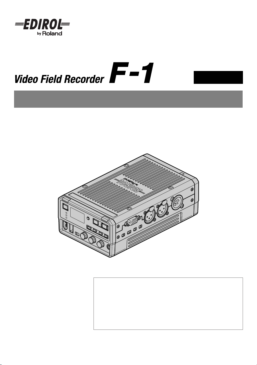
Page 1
Ver. 2.0
Owner’s Manual
Before using this unit, carefully read the sections entitled: “USING
THE UNIT SAFELY” (p. 6–8), “IMPORTANT NOTES” (p. 9–10), and
“An Important Notice Regarding the Software” (p. 64–67).
These sections provide important information concerning the proper
operation of the unit. Additionally, in order to feel assured that you
have gained a good grasp of every feature provided by your new unit,
Owner’s Manual should be read in its entirety. The manual should be
saved and kept on hand as a convenient reference.
Copyright © 2009 ROLAND CORPORATION
All rights reserved. No part of this publication may be reproduced in any
form without the written permission of ROLAND CORPORATION.
Page 2
Introduction
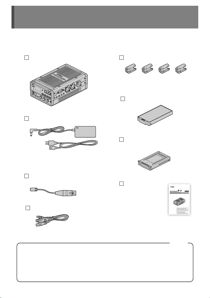
Confirm the Contents of the Package
The F-1 includes the following items. Please take a moment to confirm that all of these items
have been included with the F-1. If you find that any item is missing, contact the nearest
authorized EDIROL/Roland distributor in your country.
F-1
AC adaptor/Power cord
* The shape of the power cord’s plug varies
depending on the country.
Conversion cable
(AC adaptor ↔ 4pin XLR type connector)
Ferrite core x 4
* Attach these to the i.LINK cable and the
LAN cable.
Battery case
Removable storage
(F1-HD120: 120 GB Hard Disk Drive)
Owner’s manual
USB cable
IMPORTANT: THE WIRES IN THIS MAINS LEAD ARE COLOURED IN ACCORDANCE WITH THE FOLLOWING CODE.
As the colours of the wires in the mains lead of this apparatus may not correspond with the coloured markings identifying
the terminals in your plug, proceed as follows:
The wire which is coloured BLUE must be connected to the terminal which is marked with the letter N or coloured BLACK.
The wire which is coloured BROWN must be connected to the terminal which is marked with the letter L or coloured RED.
Under no circumstances must either of the above wires be connected to the earth terminal of a three pin plug.
(Y type with power supply)
BLUE:
NEUTRAL
BROWN:
LIVE
2
For the U.K.
Page 3

Main Features
●
Direct capture of HDV/DV streams
HDV/DV file capture can be completed anywhere during recording.
●
Connect to a PC via USB and copy materials in faster than real time
The F-1 and a PC can be connected via USB and the captured files can be imported. By
importing your material via USB you can save time by eliminating the need to capture to your
software in real time.
●
Synchro Capture for audio input
Audio can be captured in stereo and synchronized with the video capture. The captured audio
can be imported directly in a non-linear editing environment on a PC.
●
Unlimited capture time
The file system is NTFS. A captured file can be as large as permitted by storage.
* Only when the [CH3/4] switch is “OFF.”
●
Versatile recording modes
“Pre-Record” mode captures the material starting three seconds before you initiated the
capture, and “Loop Record” mode keeps capturing while continuing to erase older files.
●
Removable storage
The internal F-1 storage drives can be inserted or removed. Drives that has been removed can
be connected to a PC with the included USB cable. If you keep a number of storage units on
hand, and switch them as needed, you can resume recording right away.
●
Two power systems (DC 12V power supply, AA battery operation)
The unit can be operated on a DC 12V power supply or by AA batteries. Use them together for
a redundant failover power supply.
●
Audio input using a phantom power
The audio input connector is equipped with a phantom power.
●
Material check on a VGA display
By inputting the DISPLAY OUT signal to a display that supports VGA input, the material list
stored on the F-1 can be shown.
●
Connect directly to a USB mass storage device to copy materials
Connect the F-1 to a handy USB memory device or USB hard disk to extract data from the F-1.
●
Network support
Since there is an onboard LAN connector, materials can be copied to a PC via a local Ethernet
network, and the unit can even be controlled remotely by a PC.
●
Linkage with the EDIROL VC-50HD field converter
By using the F-1 in conjunction with the VC-50HD field converter, SDI signals can be captured
as HDV or MPEG with selectable bit rate.
3
Page 4

Table of Contents
Please read before using.
USING THE UNIT SAFELY................................................................................................. 6
IMPORTANT NOTES ..........................................................................................................9
An Important Notice Regarding the Software ...............................................................64
Introduction 2
Confirm the Contents of the Package.............................................................................. 2
Main Features..................................................................................................................... 3
Making a Recording 11
Capturing by Connecting a HDV/DV Camera ................................................................11
Capturing Video and Audio............................................................................................. 13
Checking Captured Video and Audio............................................................................. 15
Panel Descriptions 3
Front Panel .......................................................................................................................16
Rear Panel ........................................................................................................................18
Side Panel.........................................................................................................................18
Display ..............................................................................................................................20
Home Screen............................................................................................................... 20
Audio Level Screen .....................................................................................................22
Basic Operations 23
Turning Power On/Off...................................................................................................... 23
Using Batteries.................................................................................................................24
Regarding the Batteries............................................................................................... 24
Inserting the Batteries.................................................................................................. 25
Setting Battery Type .................................................................................................... 26
Operating the Menu .........................................................................................................27
Connecting to a PC 28
F-1 Folder Structure......................................................................................................... 28
Copying F-1 Materials to a PC ........................................................................................29
Connecting the F-1 to a PC ......................................................................................... 29
Connecting the Removable Storage to a PC............................................................... 30
The “F-1 Utility”............................................................................................................ 30
Disconnecting the PC .................................................................................................. 31
Copying F-1 Materials over a Network........................................................................... 32
Remotely Controlling the F-1 from the PC (F-1 Net Control)....................................... 33
4
Page 5

Table of Contents
Advanced Use 34
Arranging Materials .........................................................................................................34
Regarding Folders ....................................................................................................... 34
Deleting Material Files ................................................................................................. 35
Managing the Removable Storage .................................................................................36
Inserting/Removing...................................................................................................... 36
Deleting All Data / Initializing (Formatting) ..................................................................37
Scanning (Internal Drive Check).................................................................................. 38
Using USB Mass Storage ................................................................................................ 39
Backing Up All Material Files....................................................................................... 39
Copying the Currently Selected Material Files ............................................................40
Initializing (Formatting) ................................................................................................41
Scanning (USB Check)................................................................................................ 41
Operating by Connecting a VGA Display and Mouse................................................... 42
Configuration Settings 44
Starting Capture by Linking to a Camera ......................................................................44
Capturing while Correcting the Synchronization Gap between Audio and Video..... 44
Dividing and Capturing Data with Non-Sequential Timestamps ................................. 45
Setting the Record Mode for Capturing......................................................................... 46
Capturing using the F-1’s Internally Generated Timecode .......................................... 48
Setting Peak Hold for the Audio Level Meter ................................................................49
Setting Stereo/Monaural for WAV Files .........................................................................49
Delaying Audio Output (Audio Delay)............................................................................ 50
Setting the Date and Time............................................................................................... 51
Setting Material File Playback Mode .............................................................................. 52
Setting the Time until the Display Turns Off (Display Timer) ...................................... 53
Setting the Brightness of the Display ............................................................................ 53
Setting the Lamp Illumination Method........................................................................... 54
Setting the Time for the Power to Turn Off Automatically........................................... 54
Setting the Language for Display................................................................................... 55
Restoring the Factory Defaults (Factory Reset) ...........................................................55
Using the F-1 in Combination with the EDIROL VC-50HD ...........................................56
Appendices 62
Troubleshooting............................................................................................................... 58
Menu List ..........................................................................................................................62
Main Specification ...........................................................................................................68
Dimensions....................................................................................................................... 69
Optional Accessories ......................................................................................................70
Index.................................................................................................................................. 71
Information ........................................................................................................Back cover
5
Page 6
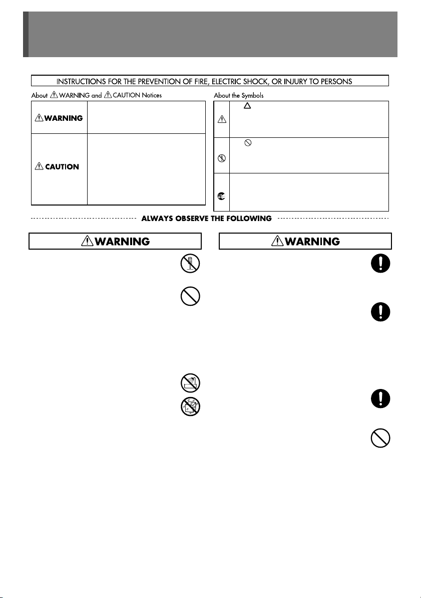
USING THE UNIT SAFELY
Used for instructions intended to alert
the user to the risk of death or severe
injury should the unit be used
improperly.
Used for instructions intended to alert
the user to the risk of injury or material
damage should the unit be used
improperly.
* Material damage refers to damage or
other adverse effects caused with
respect to the home and all its
furnishings, as well to domestic
animals or pets.
002c
●
Do not open (or modify in any way) the unit
or its AC adaptor.
..................................................................................
003
●
Do not attempt to repair the unit, or replace
parts within it (except when this manual
provides specific instructions directing you
to do so). Refer all servicing to your
retailer, the nearest EDIROL/Roland
Service Center, or an authorized Roland
distributor, as listed on the “Information”
page.
..................................................................................
004
●
Never install the unit in any of the following
locations.
•
Subject to temperature extremes (e.g.,
direct sunlight in an enclosed vehicle,
near a heating duct, on top of heatgenerating equipment); or are
•
Extremely cold; or are
•
Locations with low atmospheric
pressure; or are
•
Exposed to steam or smoke; or are
•
Subject to salt exposure; or are
•
Humid; or are
•
Exposed to rain; or are
•
Dusty or sandy; or are
•
Subject to high levels of vibration and
shakiness.
..................................................................................
The symbol alerts the user to important instructions
or warnings.The specific meaning of the symbol is
determined by the design contained within the triangle.
In the case of the symbol at left, it is used for general
cautions, warnings, or alerts to danger.
The symbol alerts the user to items that must never
be carried out (are forbidden). The specific thing that
must not be done is indicated by the design contained
within the circle. In the case of the symbol at left, it
means that the unit must never be disassembled.
The ● symbol alerts the user to things that must be
carried out. The specific thing that must be done is
indicated by the design contained within the circle. In
the case of the symbol at left, it means that the powercord plug must be unplugged from the outlet.
007
●
Make sure you always have the unit placed
so it is level and sure to remain stable.
Never place it on stands that could wobble,
or on inclined surfaces.
..................................................................................
008c
●
Be sure to use only the AC adaptor
supplied with the unit. Also, make sure the
line voltage at the installation matches the
input voltage specified on the AC adaptor’s
body. Other AC adaptors may use a
different polarity, or be designed for a
different voltage, so their use could result in
damage, malfunction, or electric shock.
..................................................................................
008e
●
Use only the attached power-supply cord.
Also, the supplied power cord must not be
used with any other device.
..................................................................................
009
●
Do not excessively twist or bend the power
cord, nor place heavy objects on it. Doing
so can damage the cord, producing
severed elements and short circuits.
Damaged cords are fire and shock
hazards!
..................................................................................
6
Page 7
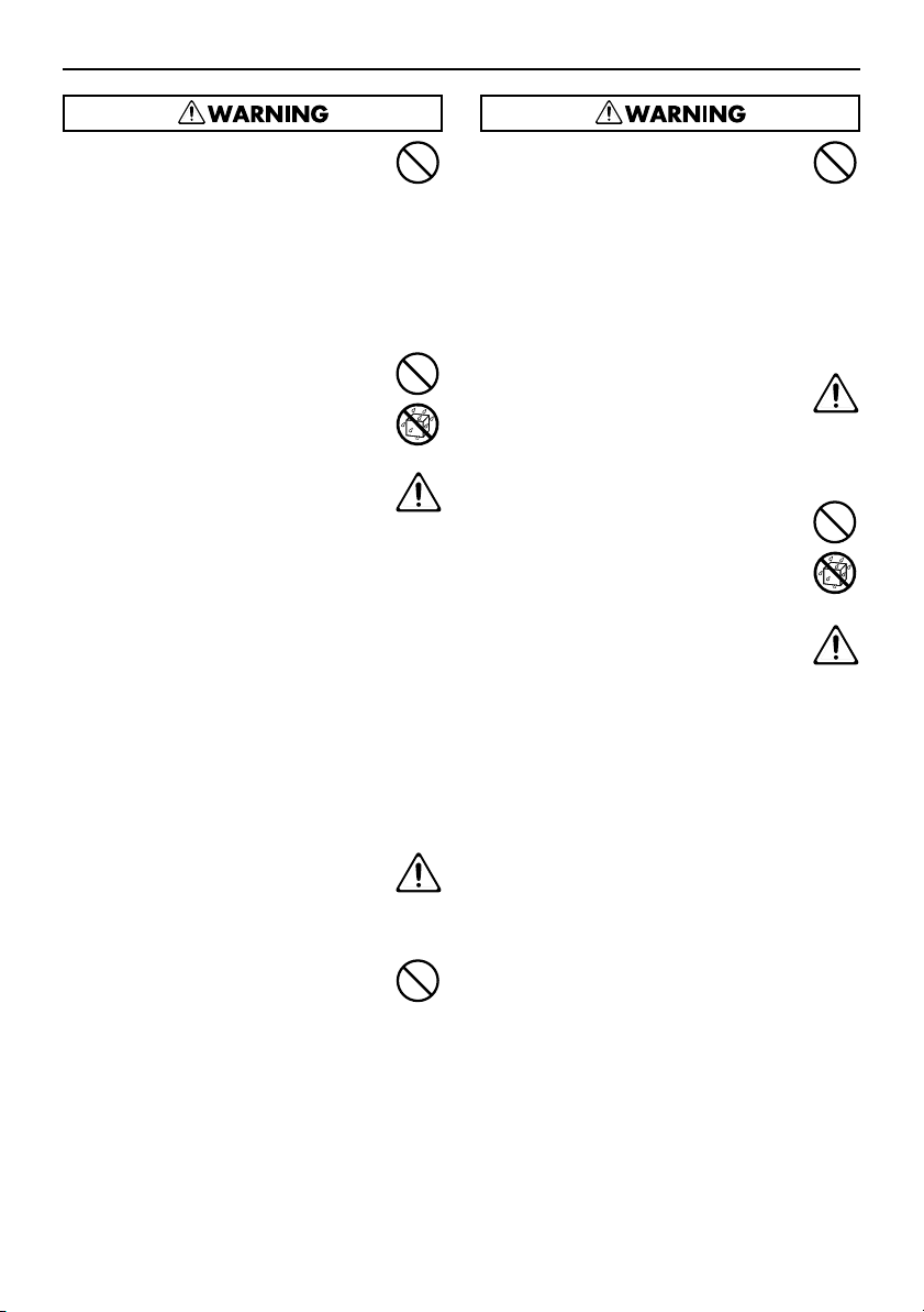
USING THE UNIT SAFELY
010
●
This unit in combination with a headphones
may be capable of producing sound levels
that could cause permanent hearing loss.
Do not operate for a long period of time at a
high volume level, or at a level that is
uncomfortable. If you experience any
hearing loss or ringing in the ears, you
should immediately stop using the unit, and
consult an audiologist.
..................................................................................
011
●
Do not allow any objects (e.g., flammable
material, coins, pins); or liquids of any kind
(water, soft drinks, etc.) to penetrate the
unit.
..................................................................................
012b
●
Immediately turn the power off, remove the
AC adaptor from the outlet, and request
servicing by your retailer, the nearest
EDIROL/Roland Service Center, or an
authorized Roland distributor, as listed on
the “Information” page when:
The AC adaptor, the power-supply cord,
•
or the plug has been damaged; or
If smoke or unusual odor occurs
•
Objects have fallen into, or liquid has
•
been spilled onto the unit; or
The unit has been exposed to rain (or
•
otherwise has become wet); or
The unit does not appear to operate
•
normally or exhibits a marked change in
performance.
..................................................................................
013
●
In households with small children, an adult
should provide supervision until the child is
capable of following all the rules essential
for the safe operation of the unit.
..................................................................................
014
●
Protect the unit from strong impact.
(Do not drop it!)
..................................................................................
015
●
Do not force the unit’s power-supply cord to
share an outlet with an unreasonable
number of other devices. Be especially
careful when using extension cords—the
total power used by all devices you have
connected to the extension cord’s outlet
must never exceed the power rating (watts/
amperes) for the extension cord. Excessive
loads can cause the insulation on the cord
to heat up and eventually melt through.
..................................................................................
016
●
Before using the unit in a foreign country,
consult with your retailer, the nearest
EDIROL/Roland Service Center, or an
authorized Roland distributor, as listed on
the “Information” page.
..................................................................................
019
●
Batteries must never be recharged, heated,
taken apart, or thrown into fire or water.
..................................................................................
027
●
Never expose Battery to excessive heat
such as sunshine, fire or the like.
..................................................................................
7
Page 8
USING THE UNIT SAFELY
101b
●
The unit and the AC adaptor should be
located so their location or position does
not interfere with their proper ventilation.
..................................................................................
102c
●
Always grasp only the plug on the AC
adaptor cord when plugging into, or
unplugging from, an outlet or this unit.
..................................................................................
111: Selection
●
If used improperly, batteries may explode
or leak and cause damage or injury. In the
interest of safety, please read and observe
the following precautions (p. 24).
1
Carefully follow the installation
•
instructions for batteries, and make sure
you observe the correct polarity.
Avoid using new batteries together with
•
used ones. In addition, avoid mixing
different types of batteries.
If not using the unit for several months,
•
please remove the batteries.
If a battery has leaked, use a soft piece
•
of cloth or paper towel to wipe all
remnants of the discharge from the
battery compartment. Then install new
batteries. To avoid inflammation of the
skin, make sure that none of the battery
discharge gets onto your hands or skin.
Exercise the utmost caution so that none
of the discharge gets near your eyes.
Immediately rinse the affected area with
running water if any of the discharge has
entered the eyes.
Never keep batteries together with
•
metallic objects such as ballpoint pens,
necklaces, hairpins, etc.
Do not allow any foreign metal objects to
•
touch the terminals of the battery case.
Doing so may cause the batteries to
short and the battery case may overheat
or catch fire.
Before use, carefully read the cautions
•
printed on the battery as well as the
owner’s manual that accompanies the
battery.
..................................................................................
103b
●
At regular intervals, you should unplug the
AC adaptor and clean it by using a dry
cloth to wipe all dust and other
accumulations away from its prongs. Also,
disconnect the power plug from the power
outlet whenever the unit is to remain
unused for an extended period of time. Any
accumulation of dust between the power
plug and the power outlet can result in poor
insulation and lead to fire.
..................................................................................
104
●
Try to prevent cords and cables from
becoming entangled. Also, all cords and
cables should be placed so they are out of
the reach of children.
..................................................................................
106
●
Never climb on top of, nor place heavy
objects on the unit.
..................................................................................
107c
●
Never handle the AC adaptor or its plugs
with wet hands when plugging into, or
unplugging from, an outlet or this unit.
..................................................................................
108b
●
Before moving the unit, disconnect the AC
adaptor and all cords coming from external
devices.
..................................................................................
109b
●
Before cleaning the unit, turn off the power
and unplug the AC adaptor from the outlet.
..................................................................................
110b
●
Whenever you suspect the possibility of
lightning in your area, disconnect the AC
adaptor from the outlet.
..................................................................................
120
●
Always turn the phantom power off when
connecting any device other than
condenser microphones that require
phantom power. You risk causing damage
if you mistakenly supply phantom power to
dynamic microphones, audio playback
devices, or other devices that don’t require
such power. Be sure to check the
specifications of any microphone you
intend to use by referring to the manual
that came with it.
This instrument’s phantom power:
DC 48V (unloaded maximum),
14 mA (maximum load)
..................................................................................
8
Page 9

IMPORTANT NOTES
Power Supply: Use of Batteries
301
●
Do not connect this unit to same electrical outlet
that is being used by an electrical appliance that is
controlled by an inverter (such as a refrigerator,
washing machine, microwave oven, or air
conditioner), or that contains a motor. Depending
on the way in which the electrical appliance is
used, power supply noise may cause this unit to
malfunction or may produce audible/visible noise.
If it is not practical to use a separate electrical
outlet, connect a power supply noise filter
between this unit and the electrical outlet.
302
●
The AC adaptor will begin to generate heat after
long hours of consecutive use. This is normal, and
is not a cause for concern.
303a
●
The use of an AC adaptor is recommended as the
unit’s power consumption is relatively high. When
using batteries, please use nickel metal hydride
batteries.
304a
●
When installing or replacing batteries, always turn
off the power on this unit and disconnect any other
devices you may have connected. This way, you
can prevent malfunction.
Placement
351
●
Using the unit near power amplifiers (or other
equipment containing large power transformers)
may induce hum or visible noise. To alleviate the
problem, change the orientation of this unit; or
move it farther away from the source of
interference.
352a
●
This device may interfere with radio and television
reception. Do not use this device in the vicinity of
such receivers.
352b
●
Noise may be produced if wireless
communications devices, such as cell phones, are
operated in the vicinity of this unit. Such noise
could occur when receiving or initiating a call, or
while conversing. Should you experience such
problems, you should relocate such wireless
devices so they are at a greater distance from this
unit, or switch them off.
354a
●
Do not expose the unit to direct sunlight, place it
near devices that radiate heat, leave it inside an
enclosed vehicle, or otherwise subject it to
temperature extremes. Excessive heat can
deform or discolor the unit.
Placement
355b
●
When moved from one location to another where
(continued)
the temperature and/or humidity is very different,
water droplets (condensation) may form inside the
unit. Damage or malfunction may result if you
attempt to use the unit in this condition. Therefore,
before using the unit, you must allow it to stand for
several hours, until the condensation has
completely evaporated.
360
●
Depending on the material and temperature of the
surface on which you place the unit, its rubber feet
may discolor or mar the surface.
You can place a piece of felt or cloth under the
rubber feet to prevent this from happening. If you
do so, please make sure that the unit will not slip
or move accidentally.
***]
●
Depending on the circumstances of a particular
setup, you may experience a discomforting
sensation, or perceive that the surface feels gritty
to the touch when you touch this device,
microphones connected to it, or the metal portions
of other objects. This is due to an infinitesimal
electrical charge, which is harmless to humans;
however, if you are concerned, please use
batteries as necessary.
Maintenance
401a
●
For everyday cleaning wipe the unit with a soft,
dry cloth or one that has been slightly dampened
with water. To remove stubborn dirt, use a cloth
impregnated with a mild, non-abrasive detergent.
Afterwards, be sure to wipe the unit thoroughly
with a soft, dry cloth.
402
●
Never use benzine, thinners, alcohol or solvents
of any kind, to avoid the possibility of discoloration
and/or deformation.
Memory Backup
501a
●
When there is no battery power to the F-1, the
date/time settings can be saved for up to about
thirty days. If batteries are inserted as a backup
power supply (p. 25), the date/time settings can
be maintained for a longer period.
Additional Precautions
559a
●
When you need to transport the unit, package it in
the box (including padding) that it came in, if
possible. Otherwise, you will need to use
equivalent packaging materials.
9
Page 10

IMPORTANT NOTES
Additional Precautions
551
●
Damage or breakdown of the unit or mistakes in
(continued)
operation may result in the loss of data stored in
memory. To avoid problems in the event of the
loss of important data, we recommend to save the
data to your computer or USB mass storage.
552
●
Unfortunately, it may be impossible to restore the
contents of data that was stored on a removable
storage, or USB mass storage once it has been
lost. Roland Corporation assumes no liability
concerning such loss of data.
553
●
Use a reasonable amount of care when using the
unit’s buttons, sliders, or other controls; and when
using its jacks and connectors. Rough handling
can lead to malfunctions.
554
●
Never strike or apply strong pressure to the display.
556
●
When connecting / disconnecting all cables, grasp
the connector itself—never pull on the cable. This
way you will avoid causing shorts, or damage to
the cable’s internal elements.
Handling Hard Disks
Important Performance and Image Data
811
●
Once a hard disk fails to function normally, all data
that has been stored on it could be destroyed.
All hard disks eventually wear out.
recommend that you consider the hard disk not as
a permanent storage site, but as a place to store
data temporarily. We also recommend that you
back up important performance and image data
that cannot be recorded again onto your computer
or USB mass storage (p. 29, 32, 39, 40).
Note that Roland assumes no liability whatsoever,
including monetary compensation, for the loss of
any recorded content in the event of the
malfunction of, or physical damage to the hard
disk, or for any direct or incidental damages
resulting from the loss of such data.
Precautions Regarding Setup and Use
812
●
Certain hard disk setup procedures and usage
conditions may result in the corruption of recorded
data, malfunctioning, or physical damage to the
disk, so be sure to observe the following
precautions.
Do not subject the hard disk to vibration or
•
shock, especially while the unit is in operation.
Do not set up the unit in any location where it
•
may be affected by vibration from external
sources, or on any surface that is not stable.
We
Handling Hard Disks
Please do not block the cooling fan vent on the
•
(continued)
side panel.
Do not leave the unit in any environment
•
subject to temperature extremes; for example,
in a closed automobile in summer or outdoors
during winter.
Do not use the unit in locations of high
•
temperature or high humidity, in locations of
extremely low temperature or air pressure, or in
locations that experience sudden changes in
temperature.
If batteries are not installed, please do not
•
unplug the unit from the outlet or turn off the
breaker at the installation site while the power is
turned on.
Emergency Procedures
813
* The following procedures are to be used as
emergency measures only, and are not
recommended for normal operation.
●
If the device fails to respond to operational
commands or does not complete operations, use
the following procedures to turn off the power:
•
Hold down the [ (power)] button for about
four seconds to switch off the power.
Unplug the power cord from the electrical outlet.
•
(If batteries are installed, remove the battery
case.)
If the unit does not operate normally when the
power is turned on again, it may mean that the
hard disk has been damaged. In such instances,
consult your dealer or the nearest EDIROL/
Roland Service Center. Note, however, that it may
not be possible to recover any data from the hard
disk once it has been lost.
Also, please perform periodic scans of the hard
disk (p. 38) even if operating normally.
Copyright
851
●
Recording, duplication, distribution, sale, lease,
performance, or broadcast of copyrighted material
(musical works, visual works, broadcasts, live
performances, etc.) belonging to a third party in
part or in whole without the permission of the
copyright owner is forbidden by law.
853
●
Do not use this unit for purposes that could
infringe on a copyright held by a third party. We
assume no responsibility whatsoever with regard
to any infringements of third-party copyrights
arising through your use of this unit.
10
Page 11

Making a Recording
Capturing by Connecting a HDV/DV Camera
Connect an HDV/DV camera to the F-1 with the i.LINK cable, and capture the camera output.
Preparations
1
Install the removable storage included with the F-1.
* Make sure to switch off the power before installing the removable storage. Failure to do so may
result in damage to the contents of the removable storage.
Unlock the rear cover, then open it.
With the grooved side facing up, insert the removable
storage.
With the handle lowered, firmly insert the removable
storage until it reaches the back.
Close the rear cover and lock it.
2
Connect the AC adaptor.
Conversion cable
(included)
Power connector
* Place the AC adaptor so the side with the
indicator faces upwards and the side with
textual information faces downwards. The
indicator will light when you plug the AC
adaptor into an AC outlet.
Lamp
AC adaptor
(included)
Removable
storage
Power cord
(included)
Handle
Power outlet
* The shape of the power cord’s plug
varies depending on the country.
* Batteries can be used as backup power. If batteries are used, even if power from the AC
adaptor is cut off by a power outage, the capture process will continue.
See “Using Batteries” (p. 24) for details.
3
Attach the included ferrite cores to both ends of the i.LINK cable.
Insert the i.LINK cable in the ferrite core, and close and press the ferrite core together
until you hear a click.
Ferrite core
(included)
Ferrite core
(included)
* Make sure to attach the ferrite core before
using the i.LINK cable.
11
Page 12
Making a Recording
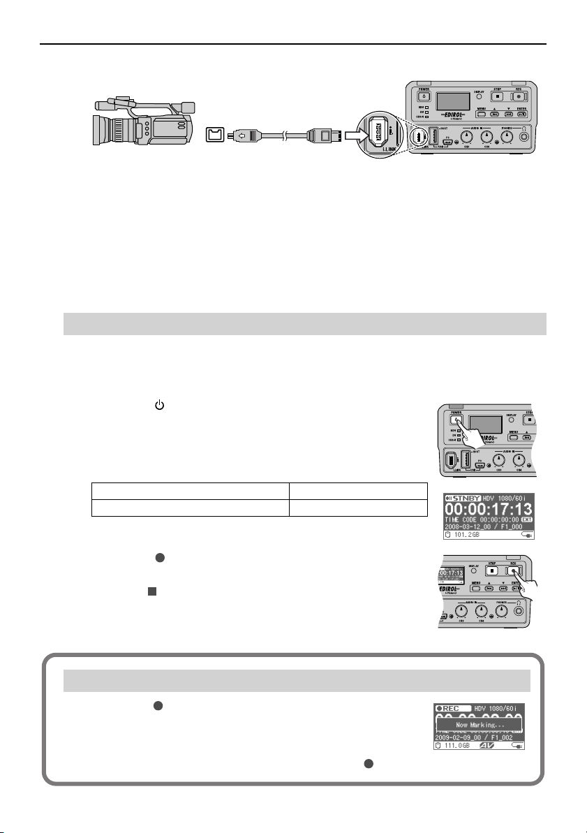
4
Connect the F-1 and HDV/DV camera with the i.LINK cable.
i.LINK
connector
i.LINK cable
* There are two types of i.LINK cable connectors: 6-pin and 4-pin. Make sure to use the i.LINK
cable that matches the device that you are using.
* The i.LINK cable unplugs easily, so be careful when filming in busy locations.
* To prevent malfunction, always turn off the power on all devices before making any
connections.
* The EDIROL DV-7R and DV-7PR are not supported.
* To ensure stable capture, do not connect anything to the USB connector.
i.LINK connector
Capturing
1
Put the HDV/DV camera in “Camera Mode” and turn on the power.
* “Camera Mode” may be called by another name, depending on the camera manufacturer.
Press the [ (POWER)] button on the F-1 to turn on power.
2
The POWER lamp lights when power is turned on. Please wait until
the Home screen is displayed.
The status lamp lights according to the format of the connected
camera.
For HDV format or MPEG-2 TS format
For DV format The DV lamp lights.
* It may take up to 10 seconds for the camera to be recognized.
The HDV lamp lights.
Home screen
12
Press the [ (REC)] button on the F-1 to start capturing
3
video.
Press the [ (STOP)] button to stop capture.
* See “Checking Captured Video and Audio” (p. 15) when checking on
the captured video.
Using Markers
If you press the [ (REC)]
(F1_xxx.txt) will be created containing the following contents. While this
is being done, the message shown at right will appear.
(1) Timecode (2) Value of the recording counter, when the [ (REC)] button was pressed
during capture, a marker file
button
Page 13
Making a Recording
Capturing Video and Audio
You can capture high quality audio from the microphone input and line input.
Audio capture happens at the same time as HDV/DV stream capture. You can capture the
audio on location and synchronize to the video.
* The timing of the capture of video and audio will not match perfectly. A slight gap (a few frames)
occurs between the timing of the capture of audio and video, because although audio is input in real
time, the HDV/DV stream output from the camera is not in real time.
The timing gap between video and audio capture can be corrected. See “Capturing while Correcting
the Synchronization Gap between Audio and Video” (p. 44) for details.
Preparations
1
Make preparations following steps 1–3 of “Preparations” (p. 11–12) above.
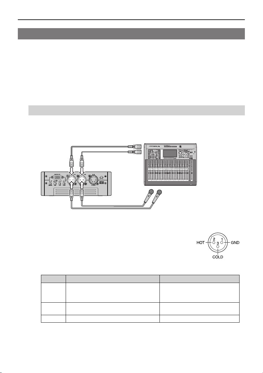
2
Connect the F-1 and the audio device.
AUDIO IN connector
Audio device
LR
Microphone
* To prevent malfunction and/or damage to other devices, always turn down the volume, and
turn off the power on all devices before making any connections.
* Use a balanced (XLR) type connector for the AUDIO IN connector.
Please connect the device after verifying the wiring configuration. The
figure at left shows the AUDIO IN connector wiring.
3
Set the switch on the side panel of the F-1.
Use one of the following settings for the connected device.
Switch When connecting a microphone When connecting to a line input
[GAIN]
[+48V]
[CH3/4]
* Supplying phantom power to a dynamic microphone may result in damage. Please thoroughly
read the instruction manual for the device that you are using. When not using a condenser
microphone requiring phantom power, please set the [+48V] switch to “OFF.”
-20 dB or MIC
Set to “-20 dB” to decrease microphone input
sensitivity.
Set to “ON” only when connecting a condenser
microphone that requires phantom power.
ON ON
LINE
OFF
13
Page 14
Making a Recording
Capturing
1
Put the HDV/DV camera in “Camera Mode” and turn on the power.
Turn power on to the audio device.
2
3
Turn power on to the F-1.
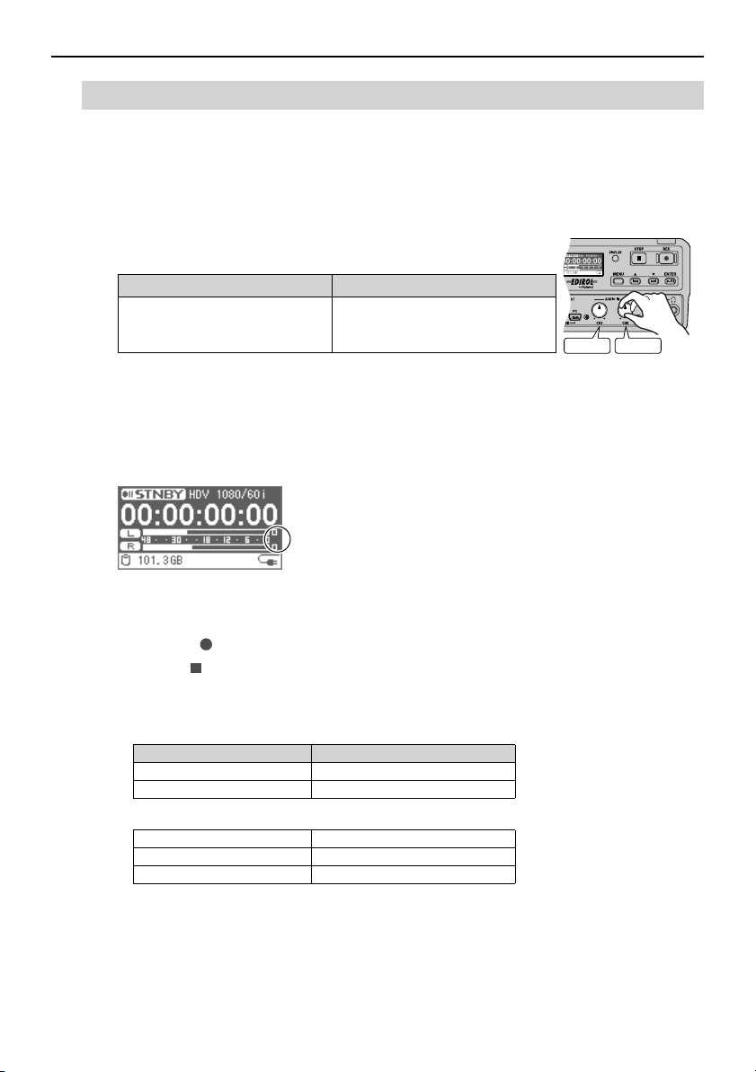
4
Turn the [AUDIO IN Level] knob to adjust the input level of
the audio.
When connecting a microphone When connecting to the line input
Point the microphone at the audio
source and adjust the input level with
the [AUDIO IN Level] knob.
The audio input level can be checked with the Audio Level Meter on
the Audio Level screen. The Home screen (two types) and Audio Level screen switch
each time the [DISPLAY] button is pressed (p. 20).
To capture the highest quality audio, adjust so that the level meter is as high as you can
get it without causing the clip lamp to light.
Audio Level screen
Increase the audio output level on the
audio device. Adjust the input level
with the [AUDIO IN Level] knob.
Clip lamp
CH3=L CH4=R
14
* If you hear acoustic feedback (a squealing sound) while using the mic, try changing the
direction of the mic, moving it away from the speakers, or lowering the speaker volume.
5
Press the [ (REC)] button on the F-1 to start capturing video and audio.
Press the [ (STOP)] button to stop capture.
* If the [CH3/4] switch is “ON,” the limit on the amount of time that capture can take place
continuously varies depending on the “WAV Mode” setting (p. 49), as follows. When the time
limit is reached, capture will stop automatically.
“WAV Mode” setting
Stereo
Mono X 2 6 hours
* The captured audio is saved into the following audio file format.
Format WAVE (BWF format)
Sampling Rate 48 kHz
Bit Rate 16 bit
The factory default setting is to create stereo WAV files. You can also create monaural WAV
files for each channel. See “Setting Stereo/Monaural for WAV Files” (p. 49) for details.
* To capture audio only, please do not connect anything to the i.LINK connector.
* The timecode included in the HDV/DV stream is also recorded to the WAV file.
* See “Checking Captured Video and Audio” (p. 15) when checking on the captured video and
audio.
Continuous capture time
3 hours
Page 15
Checking Captured Video and Audio
1
Put the HDV/DV camera in “Deck Mode” and turn on the power.
* “Deck Mode” may be called by another name, depending on the camera manufacturer.
2
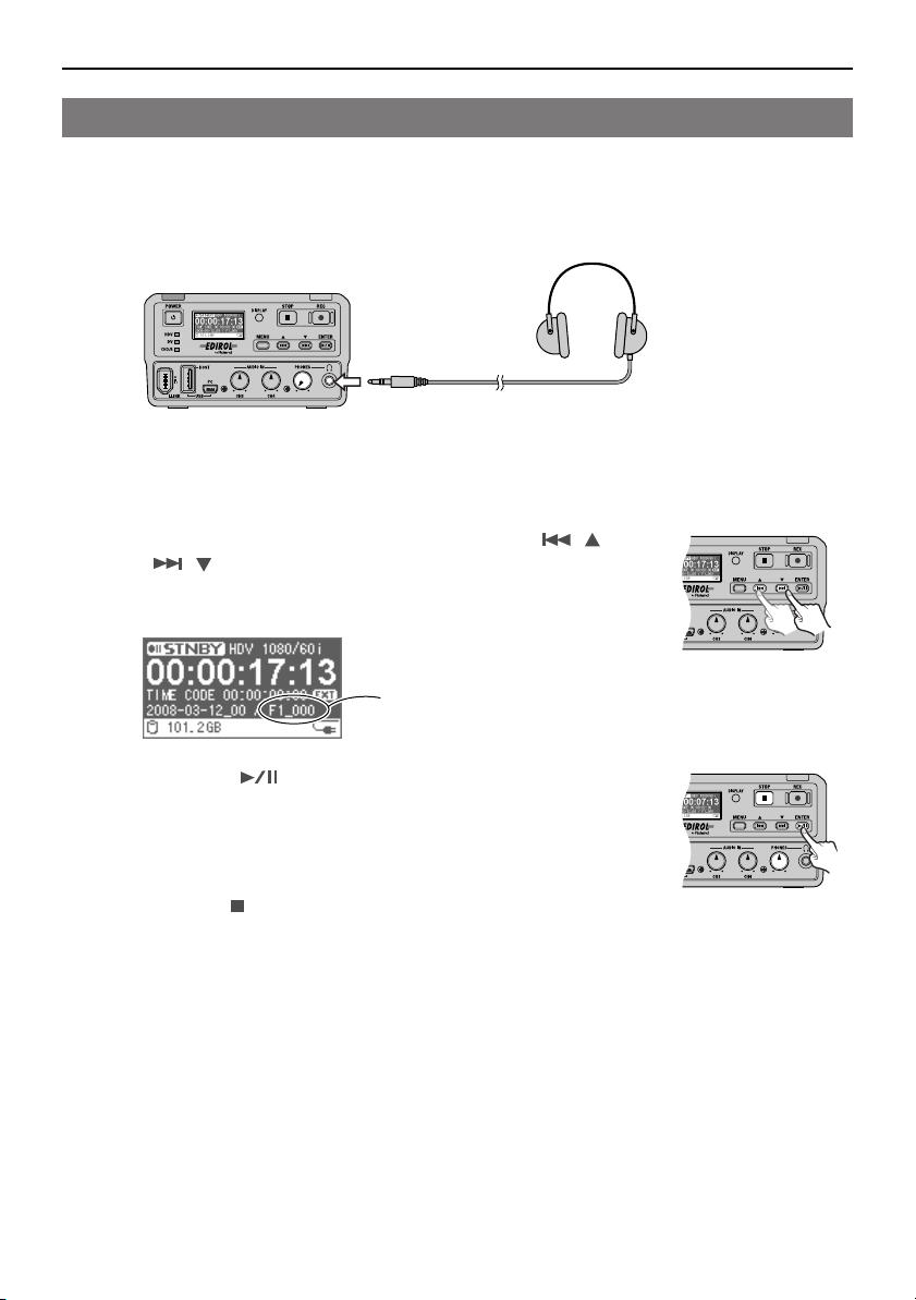
To listen to the audio, connect headphones to the PHONES jack.
PHONES jack
The captured audio is output from the PHONES jack. Before playback, turn down the
headphone volume with the [PHONES Level] knob.
* Audio that is embedded with the HDV/DV media is not output from the PHONES jack.
3
Select the material file to play back with the [ ( )]
[ ( )] buttons.
The name of the currently selected material file is displayed on the
Home screen.
Making a Recording
Material file name
4
Press the [ (ENTER)] button on the F-1.
Playback starts. The video is displayed on the HDV/DV camera
finder or display.
To listen to the audio, adjust the headphone volume with the
[PHONES Level] knob.
Press the [ (STOP)] button to stop playback.
* The timecode shown on the F-1’s display does not match the timecode shown on the HDV/DV
camera display. This is due to a video delay equal to the time for digital processing by the HDV/
DV camera.
* When listening to the audio, there will be a delay between the video displayed on the HDV/DV
camera display and the audio output from the PHONES jack.
This gap in output timing can be corrected by delaying the audio. See “Delaying Audio Output
(Audio Delay)” (p. 50) for details.
* Set the format of the HDV/DV camera so it matches the format of the material file to be played.
If the formats do not match, then the stream cannot be played on the F-1.
There are also cameras that have a mode that automatically switches the HDV/DV format.
Even if this mode is set, you may not be able to play the stream on the F-1.
15
Page 16
Panel Descriptions
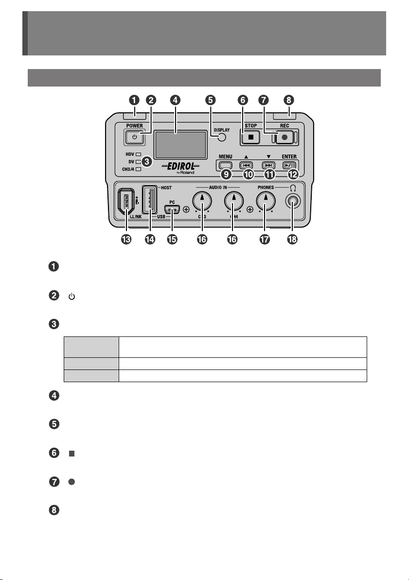
Front Panel
POWER Lamp (p. 23)
This lights when power is turned on.
[ (POWER)] Button (p. 23)
Turns power on or off.
16
Status Lamp
HDV Lamp
DV Lamp
CH3/4 Lamp
This lights when the device connected to the i.LINK connector is in HDV format
or MPEG-2 TS format.
This lights when the device connected to the i.LINK connector is in DV format.
This lights when the [CH3/4] switch on the side panel is set to “ON.”
Display (p. 20)
This displays the F-1’s operation status and menu screens.
[DISPLAY] Button (p. 20)
Switches the display between screens.
[ (STOP)] Button (p. 12, 14, 15)
Stops capture.
[ (REC)] Button (p. 12, 14, 15)
Starts the capture of the input HDV/DV stream and audio.
REC Lamp
This is illuminated during capture.
Page 17
Panel Descriptions
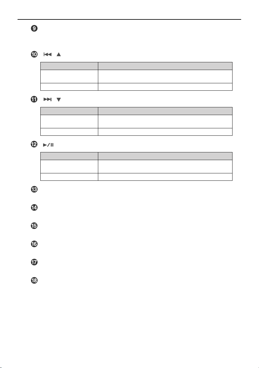
[MENU] Button (p. 27)
Shows the Menu screen on the display.
The Menu screen switches between hide/show each time the [MENU] button is pressed.
[ ( )] Button
Current Screen Operation
Home Screen
Audio Level Screen
Menu Screen Selects the previous menu item. /Changes the value of the setting.
Selects the previous file in the same folder.
[ ( )] Button
Current Screen Operation
Home Screen
Audio Level Screen
Menu Screen Selects the next menu item. /Changes the value of the setting.
Selects the next file in the same folder.
[ (ENTER)] Button
Current Screen Operation
Home Screen
Audio Level Screen
Menu Screen Sets the selected menu item or changed value.
Starts playback. It can also pause playback.
i.LINK Connector (p. 11)
Accepts connection of an HDV or DV device.
USB (HOST) Connector (p. 39, 42)
Accepts connection of a mouse or a USB device supporting the USB mass storage class.
USB (PC) Connector (p. 29)
Connect from here to the USB port on a PC using the included USB cable.
[AUDIO IN Level] Knob (CH3, CH4) (p. 15)
This adjusts the input level of audio input to the AUDIO IN connector (3CH,4CH).
[PHONES Level] Knob (p. 15)
This adjusts the volume of the output from the PHONES jack.
PHONES (headphones) Jack (p. 15)
This connects the headphones. This monitors the audio input to the AUDIO IN connector
(3CH,4CH).
17
Page 18
Panel Descriptions
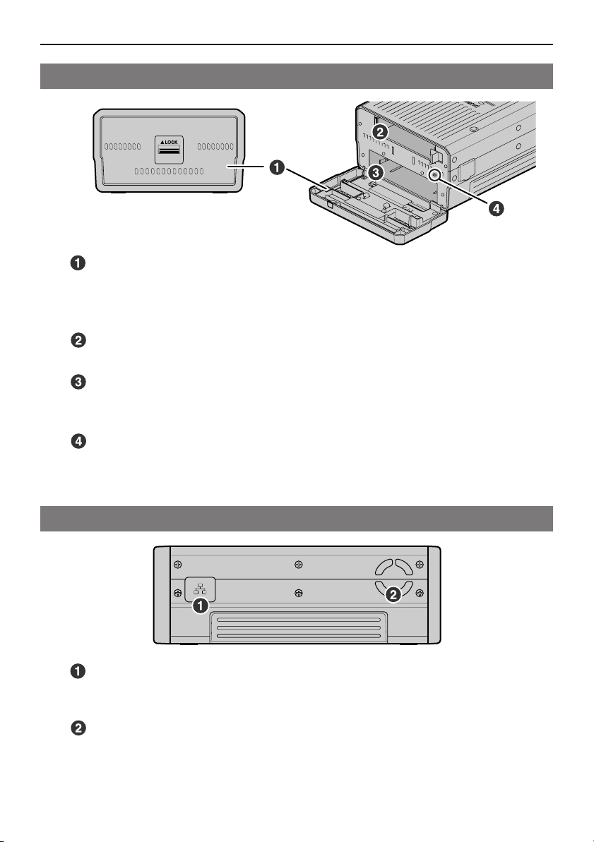
Rear Panel
Rear Cover
Slide the lock in the center of the cover down when opening or closing the rear cover.
* Do not open the rear cover unless exchanging the battery case or removable storage.
* Capture cannot begin if the rear cover is not completely closed.
Battery Case Slot (p. 25)
The battery case is inserted in this slot.
Removable Storage Slot (p. 36)
The removable storage drive is inserted in this slot.
* Only the F-1’s removable storage “F1-HD120” can be inserted.
Side Panel
18
[Open/close detection] switch
This switch detects whether the rear cover is open or closed.
* Do not touch the [Open/close detection] switch; touching it may cause malfunction.
LAN Connector (p. 33)
This is used to connect to a PC via a network using a LAN cable. F-1 materials can be
copied to a PC connected to the network.
Cooling Fan Vent
The internal cooling fan regulates temperature increases inside the F-1. Internal heat is
exhausted through here.
* Do not block the cooling fan vent. If the exhaust vent is blocked, the internal temperature will
rise and heat damage may occur.
Page 19
Panel Descriptions
Side Panel
(continued)
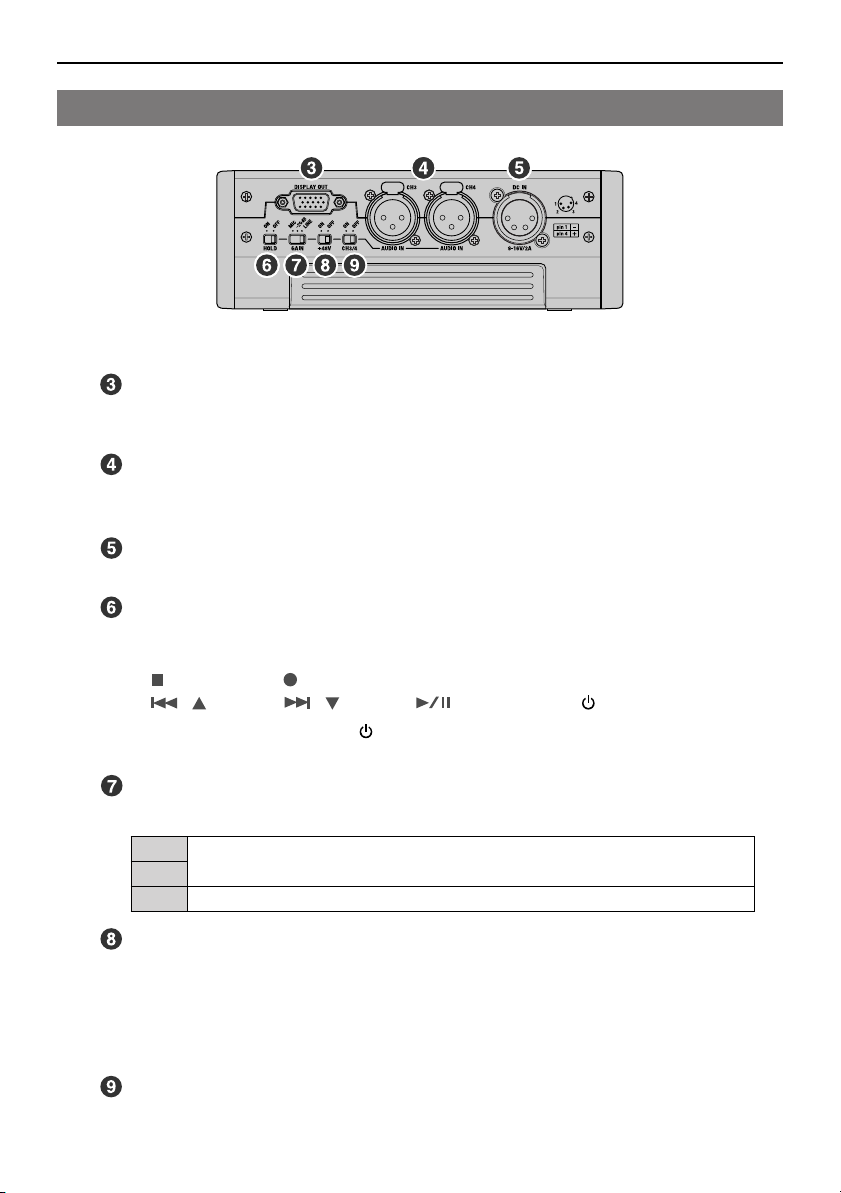
DISPLAY OUT Connector (p. 42)
This connector outputs an RGB signal (fixed SVGA format) The data in the F-1 (folder or
file) can be viewed when a VGA display is connected.
AUDIO IN Connector (CH3, CH4); XLR-type (p. 13)
Audio is input here. Accepts connection of audio devices and microphones.
Volume is adjusted with the [AUDIO IN Level] knob (p. 17).
Power Connector (p. 23)
This connects to the included AC adaptor using the included power conversion cable.
[HOLD] Switch
Sets the [HOLD] switch to the “ON” position so only the following buttons cannot be used
and to help prevent accidental operations.
•
[ (STOP)]
•
[()]• [()]• [ (ENTER)]
*1 Only when power is on. If the [ (POWER)] button is pressed while power is off, the power
is turned on.
•
[ (REC)]
•
[MENU]
•
[ (POWER)]
(*1)
[GAIN] Switch (p. 13)
Sets the gain of the audio input from the AUDIO IN connector.
This is set when using microphone input. You can set to this “-20 dB” to decrease micro-
MIC
phone input sensitivity. The audio input from the microphone is then decreased -20 dB.
-20dB
This is set when using line input.
LINE
[+48V] (Phantom Power) Switch (p. 13)
Turns the phantom power supplied to the AUDIO IN connector on/off. Set to “ON” when
connecting a condenser microphone that requires phantom power.
* Supplying phantom power to a dynamic microphone may result in damage. Please thoroughly
read the instruction manual for the device that you are using. When not using a condenser
microphone requiring phantom power, please set the [+48V] switch to “OFF.”
[CH3/4] Switch (p. 13)
Set this to “ON” when capturing audio input to the AUDIO IN connectors (3CH/4CH).
19
Page 20
Panel Descriptions
Display
This shows various information and messages, such as the current status or function settings,
according to the operation. The display shows the following three screens.
Displayed Screen Operation
Home Screen
Audio Level Screen
Menu Screen (p. 27) This screen switches between hide/show each time the [MENU] button is pressed.
* The Menu screen cannot be displayed during capture.
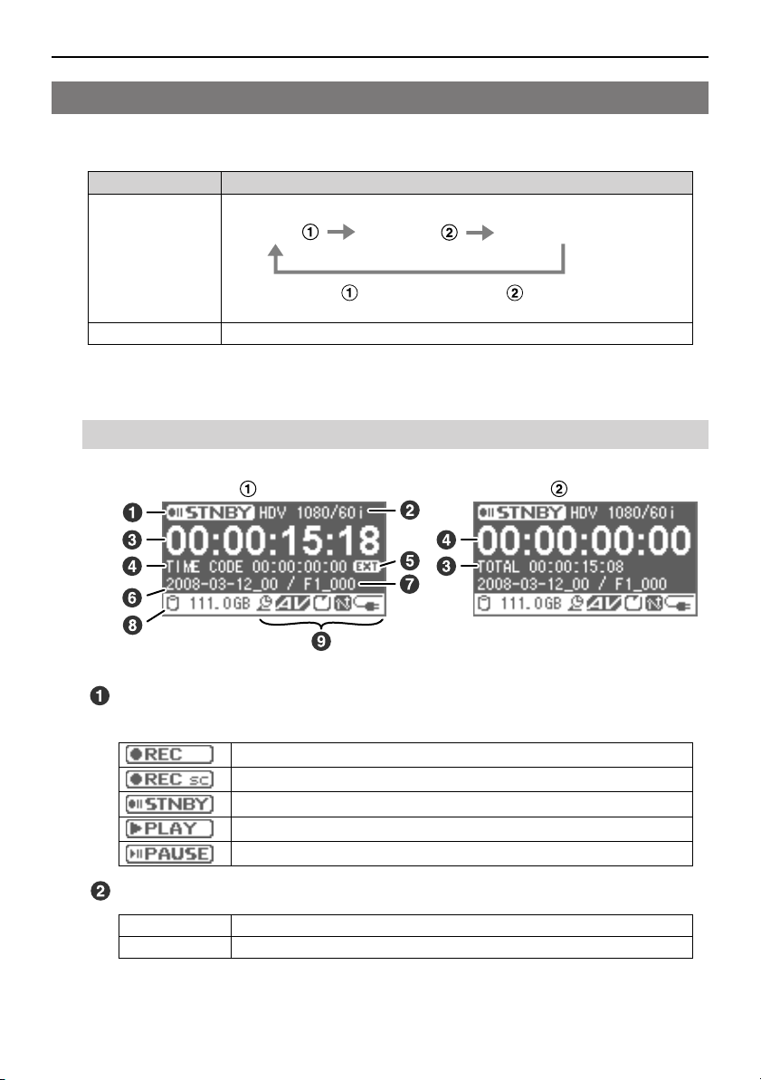
Home Screen
Home screen Home screen
The screens change as follows each time the [DISPLAY] button is pressed.
Home screen
When Home screen changes to Home screen , the timecode and total time
display locations are exchanged.
Home screen
Audio Level screen
20
Status
This indicates the current status.
During capture.
During capture with “Stream Check” (p. 45) enabled.
During standby.
During playback.
During playback pause.
Video Format
During Capture Displays the video format of the stream input from the i.LINK connector.
During Playback Displays the video format of the material being played.
Page 21
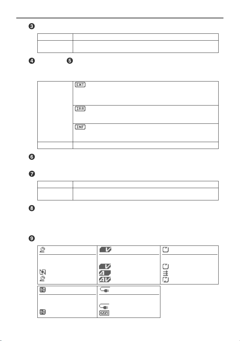
Total Time
Panel Descriptions
During Capture
During Standby/
Playback
Displays the elapsed time for capture.
Displays the length of the material currently selected.
Timecode / Timecode Mode (p. 48)
The timecode is displayed according to the “TimeCode Mode” setting (p. 48). During
capture, the displayed timecode is recorded within the video file.
During Capture/
Standby
During Playback Displays the timecode of the material being played.
: External
Displays the timecode of the device connected to the i.LINK connector.
* Displays “--:--:--:--” when no timecode is included in the input signal from the
i.LINK connector.
: Internal Rec Run
Displays the timecode internally generated by the F-1. Timecode will advance
only during capture.
: Internal Free Run
Displays the timecode internally generated by the F-1. When the F-1 is powered
up, timecode will advance regardless of operations performed.
Folder Name (p. 28, 34)
Displays the currently selected folder name. Material files are saved in the folder.
File Name (p. 28, 35)
During Capture Displays the file name of the material created after capture completes.
During Standby/
Playback
Displays the file name of the material currently selected.
Remaining Space in Removable Storage
Displays the remaining free space on the removable storage mounted on the F-1 unit.
* A low memory warning message is displayed when the remaining space on the removable
storage falls too low. If capture continues with low memory, the capture will stop eventually.
Icon Display
(p. 46)
Recording mode during capture.
(None): Normal Rec
: Loop Rec
: Pre Rec
(p. 44)
Synchro Record On/Off.
(None): Off
: On
Type of material file being played.
: Video only
: Audio only
: Audio and video
Power supply status.
: AC adaptor
: Battery (p. 24)
Material file playback mod.
: Single Repeat
:
Sequential
: Sequential Repeat
(p. 52)
21
Page 22
Panel Descriptions
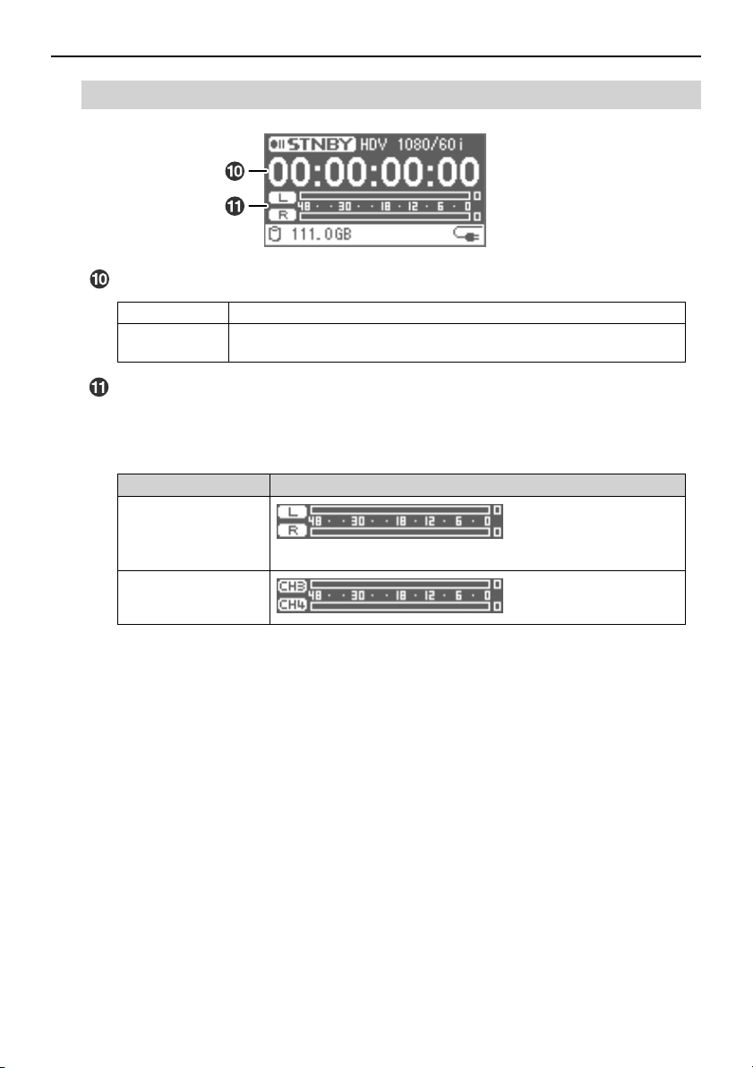
Audio Level Screen
Total Time
During Capture
During Standby/
Playback
Displays the elapsed time for capture.
Displays the length of the material currently selected.
Audio Level Meter
Displays the level of audio input to the AUDIO IN connector. The audio level is adjusted
with the [AUDIO IN Level] knob on the front panel.
The level meter display is different depending on the menu “WAV Mode” setting (p. 49).
“WAV Mode” setting Audio Level Meter Display
Stereo
The AUDIO IN connector CH3 is “L” and CH4 is “R.”
Mono X 2
22
Page 23
Basic Operations
Turning Power On/Off
Turning Power On
* Batteries can be used as backup power. If batteries are used, even if power from the AC adaptor is
cut off by a power outage, the capture process will continue.
See “Using Batteries” (p. 24) for details.
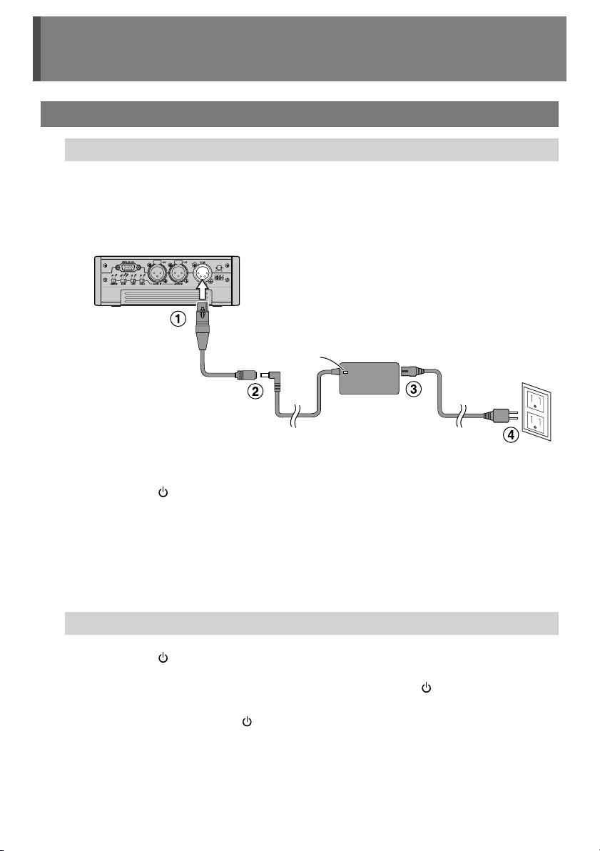
Connect the AC adaptor.
1
fig.ACadaptor.esp
* Place the AC adaptor so the side with the lamp
faces upwards and the side with textual
information faces downwards. The lamp will light
when you plug the AC adaptor into an AC outlet.
Lamp
Power cord
AC adaptor
(included)
(included)
* The shape of the power cord’s plug
varies depending on the country.
Conversion cable
(included)
Power connector
Power outlet
2
Press the [ (POWER)] button on the front panel to turn on power.
The POWER lamp lights when power is turned on. Please wait until the Home screen is
displayed.
* The F-1 is equipped with a protection circuit. A brief interval (a few seconds) after power up is
required before the unit will operate normally.
Turning Power Off
Press the [ (POWER)] button on the front panel.
1
When the “Power off.” message is displayed, press the [ (POWER)] button
2
again.
To turn off power, press the [ (POWER)] button within five seconds of the message
display.
23
Page 24

Basic Operations
Using Batteries
Batteries can be used as a backup power source. Even if power from the AC adaptor is cut off
by a power outage, power can be supplied from the batteries.
* When there is no battery power to the F-1, the date/time settings can be saved for up to about thirty
days. If batteries are inserted as a backup power supply, the date/time settings can be maintained
for a longer period.
Regarding the Batteries
Batteries that can be used
AA Nickel metal hydride batteries, AA Oxyride batteries, AA Alkaline batteries
* The F-1 cannot recharge nickel metal hydride batteries. Please use a separately purchased battery
charger.
Battery Life
Battery Type Useable Time (During Continuous Use)
Nickel Metal Hydride Batteries
Oxyride Batteries About 45 minutes
Alkaline Batteries About 30 minutes (Emergency use)
* Battery lifetimes are estimates. The actual lifetime may vary depending on the frequency of use and
use environment.
About 2 hours
24
Remaining Battery Power Indication
Shows the remaining battery power.
When the remaining battery power indication shows “ ,” the batteries are depleted.
Please replace the batteries as soon as possible. If you continue use when there is little power
left in the batteries, the power will eventually be cut off.
Full chargeLow charge
Please insert
new batteries.
* Please use the Battery Remaining Power Display as a guide.
Cautions Regarding Batteries
* Please do not mix new and used batteries or different types of batteries.
* If the unit will not be used for several months, please remove the batteries to prevent battery
leakage.
Page 25

Basic Operations
Inserting the Batteries
1
Press the [ (POWER)] button two times to turn on power.
2
Unlock the rear cover, then open it.
3
Remove the battery case.
Battery case
4
Insert eight batteries into the battery case.
Please insert the batteries as shown in the figure, taking care to orient the positive and
negative terminals correctly.
Replace the battery case into the F-1.
5
Do not allow any foreign metal objects to
touch the terminals of the battery case. Doing
so may cause the batteries to short and the
battery case may overheat or catch fire.
Close the rear cover, then lock it.
6
Set the battery type.
7
Select the type of battery used from the Menu screen. See “Setting Battery Type” on the
next page for details.
25
Page 26

Basic Operations
Setting Battery Type
Select the type of battery to be used.
* Incorrect battery settings can cause a problem in operation due to voltage drops. Please check the
batteries and make the proper settings.
1
Press the [MENU] button to access the Menu screen,
and select the “Battery Type.”
Select the “Battery Type” with the [ ( )] [ ( )]
buttons, and then press the [ (ENTER)] button.
2
Select the battery type with the [ ( )] [ ( )]
buttons.
Value Description
Alkaline
Ni-MH Nickel Metal Hydride Batteries
External External battery
Verify by pressing the [ (ENTER)] button.
3
Alkaline batteries, Oxyride batteries
26
Page 27

Basic Operations
Operating the Menu
The Menu screen appears when the [MENU] button is pressed. Various F-1 settings, such as
capture and playback settings and date/time settings, are done from the Menu screen.
* The Menu screen cannot be displayed during capture.
* See “Menu List” (p. 62) for details on the menu items.
Displaying the Menu Screen and Selecting Menu Items
Menu item
1
Press the [MENU] button to access the Menu screen.
The Menu screen switches between hide/show each time the
[MENU] button is pressed.
2
Select a menu item with the [ ( )] [ ( )]
buttons.
Verify a selected menu item by pressing the
3
[ (ENTER)] button.
When the menu has many layers, repeat steps 2–3.
Changing Settings
1
The value of a setting is changed with the [ ( )]
[ ( )] buttons.
Confirm the value you wish to set by pressing the
2
[ (ENTER)] button.
Saving Changed Content
When the value for a setting is confirmed by pressing the
[ (ENTER)] button, the setting is saved in the F-1’s internal
memory.
If you wish to cancel the changes you’ve made, press the [MENU]
button during menu operations. The settings you were in the
process of making are discarded, and you’re returned to the Home
screen or the Audio Level screen.
Menu item
Value
27
Page 28

Connecting to a PC
Connect to a PC with the included USB cable, and material captured with the F-1 (HDV video,
DV video, or audio) can be imported.
F-1 Folder Structure
When the F-1 is connected to a PC, the F-1’s removable drive is recognized as an external
drive (removable disk). The folder structure of the removable storage is shown on the PC as
follows.
F1-HD120
Folder generated when
edr
using the F-1 Utility
material
2008-04-05_00
2008-04-05_01
:
2008-06-15_00
:
Subfolders in the “material” folder
The F-1 creates folders in the “material” folder and saves materials in them.
F1_000.m2t
F1_000c34.wav
F1_000.sph
F1_000.vif
:
Files created for one capture
* A maximum of 1,000
(F1_000–F1_999) can be
created in one folder.
28
Data in the folders
When capture is performed, four types of files, “*.m2t or *.dv,” “*.wav,” “*.sph,” and “*.vif,” are
created in the folder.
*.m2t
*.dv
*.wav
*.sph
*.vif
* Copy with the “F-1 Utility” (p. 30) to manage materials without worrying about file types.
* See “Arranging Materials” (p. 34) for information on managing folders and materials.
* *.dv files cannot be browsed or edited on a PC that does not have QuickTime
download the QuickTime
http://www.apple.com/quicktime/download/
Video file in MPEG-2 TS format that is created when capturing in HDV.
Video file in DV format that is created when capturing in DV.
Audio file in WAV format.
The following WAV files are created according to the “WAV Mode” setting (p. 49).
“WAV Mode” setting File that’s created
Stereo
Mono X 2
This file is needed to play back material on the F-1. This file does not need to be copied
when using the “*.m2t” and “*.wav” files on non-linear software.
application from the Apple website.
™
c34.wav: Stereo WAV file for CH3/CH4
*
*c3.wav: Monaural WAV file for CH3
*c4.wav: Monaural WAV file for CH4
installed. Please
™
Page 29

Connecting to a PC
Copying F-1 Materials to a PC
Connecting the F-1 to a PC
Copies F-1 materials to a PC connected via USB.
•
Please use the included AC adaptor when connecting with a PC.
•
Please do not format the F-1’s removable storage with the PC. The removable storage may
become unusable.
Supported OS
Windows XP/Windows Vista (Windows)
Mac OS X (Mac)
1
Turn power on to the F-1.
2
Connect as shown in the following figure using the included USB cable.
The included USB cable has two connectors. When connecting to a PC, please connect
both USB connectors to USB ports on the PC.
USB cable
USB ports
3
Connect PC?” Once this message is displayed, select the “Yes” with the
“
(included)
USB (PC)
connector
[ ( )] [ ( )] buttons, and then press the [ (ENTER)] button.
After the F-1 is detected by the PC, copy the necessary materials.
4
After the F-1 is detected by the PC, the screen at right is
shown. The detection can take several seconds.
Detection from the PC is as follows. After reviewing “F-1
Folder Structure” on the previous page, please copy the
necessary files to the PC.
Windows
Mac
* Mac
Because the F-1’s removable storage is formatted in NTFS format, files and folders cannot be
deleted from the Mac.
When checked with My Computer or from the Explorer, the name is shown as
“F1-HD120.”
Shown on the desktop with the name “F1-HD120.”
29
Page 30

Connecting to a PC
Connecting the Removable Storage to a PC
F-1 materials can be copied to a PC by connecting the F-1’s removable storage directly to
the PC using a USB cable.
Please do not format the F-1’s removable storage with the PC. The removable storage may
become unusable.
1 Connect as shown in the following figure using the included USB cable.
The included USB cable has two connectors. When connecting to a PC, please connect
both USB connectors to USB ports on the PC.
If only one of the USB connectors is used to connect to the PC, the removable storage
may be damaged because the power supplied from the PC may be inadequate,
depending on the PC type.
USB connector
USB cable
USB ports
(included)
30
2 After the removable storage is recognized by the PC, copy the necessary
materials.
3 Disconnect from the PC.
See “Disconnecting the PC” (p. 31) for how to disconnect.
The “F-1 Utility”
The “F-1 Utility” (browser/editor) is an application that lets you use your computer to audition
and perform cut editing on material captured by the F-1.
Please download it from the Roland Systems Group website.
http://rolandsystemsgroup.net
* “F-1 Utility” and “F-1 Net Control” are only for Windows Vista/XP. There is no Mac version
available.
* The “F-1 Utility” will not run if an F-1 or removable storage (F1-HD120/F1-SSD64) is not
connected to the PC. See “Connecting the F-1 to a PC” (p. 29) for connection details.
* When the “F-1 Utility” is installed, the “F-1 Net Control” (p. 33) is installed at the same time.
Page 31

Connecting to a PC
Disconnecting the PC
Disconnects the F-1 and PC connected by USB. Follow the procedure below to disconnect,
and then unplug the USB cable.
Please do not turn F-1 power off or unplug the USB cable while the F-1 and PC are connected.
Windows
Close all applications and windows, such as Explorer, that reference the F-1’s
1
removable storage.
* If an application or window, such as Explorer, is referencing the F-1’s removable storage, then
an error will occur and you will not be able to disconnect properly.
2
Double-click on the “Safely Remove Hardware” icon ( / ) in the task tray.
The Safely Remove Hardware dialog box is shown.
Select the item indicating the F-1 from the Hardware Devices shown.
3
Please select “USB Mass Storage Device.”
4
Click on [Stop] in the dialog box.
5
When the Stop a Hardware Device dialog box appears, select the item indicating
the F-1 and click on [OK].
6
When the following message is displayed, unplug the USB cable connecting the
F-1 and PC
Windows XP
Windows Vista
When the USB cable is unplugged, the Home screen is shown on the F-1’s display.
The USB Mass Storage Device can now be safely removed from the system.
This device can now be safely removed from the computer.
Mac
Drag the F-1’s icon displayed on the desktop to the Dock.
1
When dragging to the Trash icon that is normally shown on the right of the Dock, the
Trash icon changes to and the connection can be terminated.
2
The F-1’s icon disappears from the desktop; unplug the USB cable connecting
the F-1 and PC.
When the USB cable is unplugged, the Home screen is shown on the F-1’s display.
31
Page 32

Connecting to a PC
Copying F-1 Materials over a Network
Here’s how to copy F-1 materials to a PC connected to the network.
Cautions Regarding File Sharing
The F-1 cannot have a password set for “File Sharing.” For this reason, please do not use the
PC file sharing feature on a network environment where unexpected access to the internet
may occur.
Network Settings
1
Press the [MENU] button to access the Menu screen,
and select the “Network Setting.”
Select the “Network Setting” with the [ ( )] [ ( )]
buttons, and then press the [ (ENTER)] button.
2
Select the following items with the [ ( )] [ ( )]
buttons and then configure them.
After configuration, confirm each setting with the
[ (ENTER)] button.
* “Host Name” cannot be changed.
Select the “TCP/IP” configuration method.
Value Description
Manual
DHCP When the IP address is assigned automatically
Input the “IP Address,” “Subnet mask,” and “Gateway”
addresses.
Please check with the network administrator about each of
these addresses.
Set the “Port Number.”
Set this when remotely controlling the F-1 from a PC.
Set the same number as the number set on the “F-1 Net
Control” remote control software (p. 33).
The port number is selected from “50000” to “50003.”
Please check with the network administrator for the port that is
used.
When the IP address used for the network is
specified by the network administrator.
by the router.
When set to “DHCP,” the setting in step 2- is
unnecessary.
32
Page 33

Connecting to a PC
Network Connection
1
Attach the included ferrite cores to both ends of the LAN cable
Insert the LAN cable in the ferrite core, and close and press both halves of the ferrite core
together until you hear a click.
Ferrite core (included)
Ferrite core (included)
* Please attach the ferrite core before using the LAN cable.
* Use a straight cable for the LAN cable.
Connect as shown in the following figure using the LAN cable.
2
* We recommend connecting via a network hub for stable operation.
LAN port
3
Making a network connection from a PC to the F-1.
The connection is made using the F-1’s host name. Verify the host name with “Network
Setting” → “Check Host Name” from the menu.
* See the PC instruction manual for details on how to connect to the network.
* The F-1’s workgroup name is “WORKGROUP.”
* With Mac OS X, you can access with “smb://F-1 Host Name/.”
Copy F-1 materials to the PC.
4
After reviewing “F-1 Folder Structure” (p. 28), please copy the necessary files to the PC.
* Please do not unplug the LAN cable or turn off the F-1 while files are being copied (transferred).
Failure to do so may result in the files being corrupted.
Network hub
LAN cable (straight)
Remotely Controlling the F-1 from the PC (F-1 Net Control)
“F-1 Net Control” is an application that allows you to remotely control the F-1 from a PC via a
network.
When the “F-1 Utility” (p. 30) is installed, the “F-1 Net Control” is installed at the same time.
33
Page 34

Advanced Use
Arranging Materials
Regarding Folders
The files of captured material are saved in “folders.” When shipped, one folder has already
been created. Folders can be freely created, so use them to arrange the material files.
Creating folders
1
Press the [MENU] button to access the Menu screen,
and select the “Create New Folder.”
Select the “Create New Folder” with the [ ( )] [ ( )]
buttons, and then press the [ (ENTER)] button.
A folder is created.
The folder name is the date when it was created.
(Example) “2008-04-20_01” (April 20, 2008)
Selecting folders
1
Press the [MENU] button to access the Menu screen,
and select the “Select Folder.”
Select the “Select Folder” with the [ ( )] [ ( )]
buttons, and then press the [ (ENTER)] button.
34
Select a folder with the [ ( )] [ ( )] buttons.
2
3
Confirm the choice by pressing the [ (ENTER)]
button.
The folder changes.
Deleting folders
1
Press the [MENU] button to access the Menu screen,
and select the “Delete Folder.”
Select the “Delete Folder” with the [ ( )] [ ( )]
buttons, and then press the [ (ENTER)] button.
Select the “Delete” with the [ ( )] [ ( )] buttons.
2
Confirm the choice by pressing the [ (ENTER)]
3
button.
The folder is deleted.
If all the folders are deleted, a new folder is automatically
created.
Page 35

Deleting Material Files
Deletes the currently selected material files.
Select the material to delete.
1
With the Home screen or Audio Level screen shown, select
the material to be deleted with the [ ( )] [ ( )]
buttons.
The name of the currently selected material file is displayed
on the Home screen.
2
Press the [MENU] button to access the Menu screen,
and select the “Delete File.”
Select the “Delete File” with the [ ( )] [ ( )] buttons,
and then press the [ (ENTER)] button.
3
Select the “Delete” with the [ ( )] [ ( )]
buttons.
4
Confirm the choice by pressing the [ (ENTER)]
button.
The material file is deleted.
Advanced Use
Material file name
35
Page 36

Advanced Use
Managing the Removable Storage
Inserting/Removing
The removable storage (included) is required to perform capture with the F-1.
The removable storage can be exchanged with the separately available removable storage
(F1-HD120/F1-SSD64).
Please turn off power before removing or inserting the removable storage. Failure to do so
may result in damage to the contents of the removable storage.
Inserting
Press the [ (POWER)] button two times to turn off power.
1
Unlock the rear cover, then open it.
2
With the grooved side facing up, insert the removable storage.
3
With the handle lowered, firmly insert the removable storage until it reaches the back.
Removable storage
36
Close the rear cover, then lock it.
4
Removing
1
Press the [ (POWER)] button two times to turn off power.
2
Unlock the rear cover, then open it.
3
Grasp the handle of the removable storage, and gently pull it out.
Removable storage
Handle
Close the rear cover, then lock it.
4
Page 37

Advanced Use
Deleting All Data / Initializing (Formatting)
If the same removable storage is used for capture several times, the material files may become
fragmented, and capture may not perform properly. To reduce the impact due to fragmentation,
please initialize or delete all data on the removable storage.
• When initializing or deleting all data, please be sure to employ the included AC adaptor.
•
While initializing or deleting all data, please do not turn off power. The removable storage
may become damaged.
• After initialization or deleting all data, all the data stored on the removable storage is erased.
Please back up important data on a PC or USB mass storage device (p. 29, 32, 39, 40).
•
Please do not format the F-1’s removable storage with the PC. The removable storage may
become unusable.
Deleting All Data
* When all data on the removable storage is deleted, a new folder is automatically created.
1
Press the [MENU] button to access the Menu screen,
and select the “Disk Utility.”
Select the “Disk Utility” with the [ ( )] [ ( )] buttons,
and then press the [ (ENTER)] button.
2
Select the “Clear Int. Drive.”
Select the “Clear Int. Drive.” with the [ ( )] [ ( )]
buttons, and then press the [ (ENTER)] button.
3
Select the “Yes” with the [ ( )] [ ( )] buttons.
4
Confirm the choice by pressing the [ (ENTER)]
button.
All data is deleted. Please wait.
37
Page 38

Advanced Use
Initializing (Formatting)
Initializes (formats) the removable storage in NTFS format.
* When the removable storage is initialized, a new folder is automatically created.
Press the [MENU] button to access the Menu screen,
1
and select the “Disk Utility.”
Select the “Disk Utility” with the [ ( )] [ ( )] buttons,
and then press the [ (ENTER)] button.
2
Select the “Format Int. Drive.”
Select the “Format Int. Drive” with the [ ( )] [ ( )]
buttons, and then press the [ (ENTER)] button.
Select the “Yes” with the [ ( )] [ ( )] buttons.
3
Confirm the choice by pressing the [ (ENTER)]
4
button.
Initialization begins. Initialization takes some time to complete,
so please do not turn off the power.
When using the included removable storage (F1-HD120),
initialization takes about 50 minutes to complete.
38
Scanning (Internal Drive Check)
Scans for corrupted files on the removable storage and repairs them.
When the internal drive check is performed, files that have problems are repaired, and the
frequency of errors can be reduced.
Press the [MENU] button to access the Menu screen,
1
and select the “Disk Utility.”
Select the “Disk Utility” with the [ ( )] [ ( )] buttons,
and then press the [ (ENTER)] button.
2
Select the “Check Int. Drive.”
Select the “Check Int. Drive” with the [ ( )] [ ( )]
buttons, and then press the [ (ENTER)] button.
Select the “Yes” with the [ ( )] [ ( )] buttons.
3
Confirm the choice by pressing the [ (ENTER)]
4
button.
The check of the removable drive begins. Please wait.
Page 39

Advanced Use
Using USB Mass Storage
Connect a USB mass storage device to the USB (HOST) connector and copy F-1 materials.
Please initialize (format) the USB mass storage device on the F-1 before using it. See
“Initializing (Formatting)” (p. 41) for the procedures.
USB (HOST)
connector
USB mass storage
* If the USB mass storage device has multiple partitions, the materials are copied to the partition with
the drive number that comes first.
Backing Up All Material Files
Back up (copy) all F-1 material files to a USB mass storage device.
* The “material” folder in the removable storage is backed up. See “F-1 Folder Structure” (p. 28) for
details.
Connect the USB mass storage device to the USB
1
(HOST) connector.
2
Press the [MENU] button to access the Menu screen,
and select the “Disk Utility.”
Select the “Disk Utility” with the [ ( )] [ ( )] buttons,
and then press the [ (ENTER)] button.
Select the “Backup to USB.”
3
Select the “Backup to USB” with the [ ( )] [ ( )]
buttons, and then press the [ (ENTER)] button.
4
Select the “Yes” with the [ ( )] [ ( )] buttons.
5
Confirm the choice by pressing the [ (ENTER)]
button.
Backup starts. The backup may take a while depending on
the size of the material files.
The material files (“material” folder) are stored in the root
directory of the USB mass storage device.
39
Page 40

Advanced Use
Copying the Currently Selected Material Files
Copies the currently selected material files (*.m2t / *.dv, *.wav) to the USB mass storage
device.
Connect the USB mass storage device to the USB
1
(HOST) connector.
2
Press the [MENU] button to access the Menu screen,
and select the “Disk Utility.”
Select the “Disk Utility” with the [ ( )] [ ( )] buttons,
and then press the [ (ENTER)] button.
Select the “Copy File to USB.”
3
Select the “Copy File to USB” with the [ ( )] [ ( )]
buttons, and then press the [ (ENTER)] button.
4
Select the “Yes” with the [ ( )] [ ( )] buttons.
5
Confirm the choice by pressing the [ (ENTER)]
button.
Copy starts. This may take a while depending on the size of the
material files.
The material files are stored in the root directory of the USB
mass storage device.
40
Page 41

Advanced Use
Initializing (Formatting)
Initializes (formats) the USB mass storage device in NTFS format.
*
Mac:
USB mass storage devices that have been initialized in NTFS format are read-only on Macs.
* Initialization may not be possible depending on the USB mass storage device.
•
Please do not turn off power during initialization. The USB mass storage device may
become damaged.
•
When initialized, all the data stored on the USB mass storage device is deleted. Any data
lost due to initialization cannot be recovered. Please be sure before performing initialization.
1
Press the [MENU] button to access the Menu screen,
and select the “Disk Utility.”
Select the “Disk Utility” with the [ ( )] [ ( )] buttons,
and then press the [ (ENTER)] button.
Select the “Format USB.”
2
Select the “Format USB” with the [ ( )] [ ( )]
buttons, and then press the [ (ENTER)] button.
3
Select the “Yes” with the [ ( )] [ ( )] buttons.
4
Confirm the choice by pressing the [ (ENTER)]
button.
Initialization begins. Initialization takes some time to
complete, so please do not turn off the power.
Scanning (USB Check)
Scans for corrupted files on the USB mass storage device and repairs them.
When the USB check is performed, files that have problems are repaired, and the frequency of
errors can be reduced.
1
Press the [MENU] button to access the Menu screen,
and select the “Disk Utility.”
Select the “Disk Utility” with the [ ( )] [ ( )] buttons,
and then press the [ (ENTER)] button.
Select the “Check USB.”
2
Select the “Check USB” with the [ ( )] [ ( )]
buttons, and then press the [ (ENTER)] button.
3
Select the “Yes” with the [ ( )] [ ( )] buttons.
4
Confirm the choice by pressing the [ (ENTER)] button.
The check of the USB mass storage device begins. Please wait.
41
Page 42

Advanced Use
Operating by Connecting a VGA Display and Mouse
If a VGA display and mouse are connected to the F-1, basic operations can be performed
while still in the field.
Connecting
1
Connect the VGA display/mouse to the F-1 as shown in the figure below
The screen and mouse pointer are shown on the VGA display.
VGA display
VGA cable
DISPLAY OUT
Mouse
USB (HOST) connector
* Please use a VGA display that supports “analog RGB input, 800 x 600 resolution.”
connector
42
Page 43

VGA Screen
Display
Folder List
Shows a list of folders.
File List
Shows a list of files in the currently selected folder.
Files can be displayed as file names or as thumbnails. The way they’re displayed is
changed with the following operation.
Using the
Mouse
Using the Menu
Click on the radio button ([Name list]/[Thumbnail list]) in the upper-right of the
VGA Screen to change the display.
Change the setting for the menu item “File List (VGA)” to change the display.
Value Description
Name Displays file names in a list.
Thumbnail Displays files as thumbnails.
Advanced Use
For File Name display:
File name Material length Video format
Displayed when a video-format WAV file is created.
• WAV.Stereo:
• WAV.MonoX2:
Stereo WAV file
Monaural WAV files
F-1 Panel
Displays the F-1 panel.
File Information
Displays the information of the currently selected file.
Folder Folder save location
File File name
Length Material length
(Format
information, etc.)
Video format
Displayed when a video-format WAV file is created.
• WAV.Stereo:
• WAV.MonoX2:
Stereo WAV file
Monaural WAV files
Position Bar
Shows the relative file read position.
* If you drag the position bar during playback, the audio will be muted. To resume output of the
audio, first stop the playback, then restart playback from the beginning of the file.
43
Page 44

Configuration Settings
Starting Capture by Linking to a Camera
You can synchronize the recording of the F-1 with a connected camera (Synchro Record Feature).
* For material files created by using the Synchro Record feature, the capture starts a few seconds before
the camera begins recording. This is because when the “Record Start Signal” is output from the
camera, the F-1 begins capture immediately, but the camera begins recording a few seconds later.
The timing for ending the recording is the same.
1
Press the [MENU] button to access the Menu screen,
and select the “Sync Rec.”
Select the “Sync Rec” with the [ ( )] [ ( )] buttons,
and then press the [ (ENTER)] button.
2
Select the “Sync” with the [ ( )] [ ( )] buttons.
Value Description
Disable
Sync The Synchro Record Feature is turned on. The
3
Verify by pressing the [ (ENTER)] button.
When the Synchro Record Feature is on, the Synchro Record
Icon ( ) is shown at the bottom of the Home screen.
When the F-1 [ (STOP)] button is pressed during Synchro
Recording, capture is stopped. At the same time, the “Sync
Rec” setting is changed to “
The Synchro Record Feature is turned off.
start of capture is linked to a camera.
Disable
.”
Capturing while Correcting the Synchronization Gap between Audio and Video
By setting a delay for audio to be captured, you can correct the synchronization gap between
audio and video at the time of capture.
* Depending on the camera used, the synchronization gap may differ for each capture, so the desired
results of the correction may not be obtained.
1
Press the [MENU] button to access the Menu screen,
and select the “Audio Sync.”
Select the “Audio Sync” with the [ ( )] [ ( )]
buttons, and then press the [ (ENTER)] button.
Select the audio delay with the [ ( )] [ ( )]
2
buttons.
Value Description
44
0–30
3
Verify by pressing the [ (ENTER)] button.
Larger numbers indicate a longer audio delay.
Page 45

Configuration Settings
Dividing and Capturing Data with Non-Sequential Timestamps
If the timestamp of the data being output from the HDV camera becomes non-sequential, the
data can now be automatically divided at non-sequential segments and captured separately.
Some non-linear editing applications may fail to load data that contains non-sequential
segments. In this case, first set the F-1 so that it will divide the data at the non-sequential
segments, and then begin capturing.
* The timestamp of the data that is output from i.LINK may become non-sequential when the HDV
camera begins recording after awaking from a Sleep state, or when the tape is exchanged.
1
Press the [MENU] button to access the Menu screen,
and select the “Stream Check.”
Select the “Stream Check” with the [ ( )] [ ( )]
buttons, and then press the [ (ENTER)] button.
2
Select the “Enable” with the
buttons.
Value Description
Disable
Enable If a non-sequential segment occurs in the data,
Even if the data contains non-sequential
segments, all data, including the non-sequential
segments, will be recorded.
the data will automatically be divided at the nonsequential segment.
[ ( )] [ ( )]
3
Verify by pressing the [ (ENTER)] button.
If “Stream Check” is set to “Enable,” the status indication will
show “sc” during capture.
45
Page 46

Configuration Settings
Setting the Record Mode for Capturing
In addition to the basic capture operation (p. 12), you can choose from two other capture modes:
Loop Record, which repeatedly starts and stops capturing at the specified intervals of time, and
Pre-Record, which starts recording video from three seconds before you initiated capture.
On the F-1, you can change the “Rec Mode” setting to specify how capture is to occur. Each
mode differs as shown in the table below.
Time at which capture begins.
Normal Rec
Loop Rec The moment you press the [ (REC)] button.
Pre Rec Three seconds before you press the [ (REC)] button.
Maximum file length
Normal Rec
Loop Rec The time specified by the “Loop Length” (p. 47).
Pre Rec From the start of capture to when you press the [ (STOP)] button, or until the
Operation when removable storage has no remaining space
Normal Rec
Loop Rec Oldest file in the “+LoopRec” folder is deleted and capture starts anew.
Pre Rec Capture is stopped.
Location where file is created
Normal Rec
Loop Rec In the “+LoopRec” folder inside a folder below the “material” folder.
Pre Rec In a folder below the “material” folder (p. 28).
The moment you press the [ (REC)] button.
From the start of capture to when you press the [ (STOP)] button, or until the
maximum length of time over which a capture can take place has been exceeded.
maximum length of time over which a capture can take place has been exceeded.
Capture is stopped.
In a folder below the “material” folder (p. 28).
46
* If "Codec type" is set to "MPEG-2 TS" (p. 56), the "Pre-record" time (3 seconds) will change
depending on the bit rate. (Anywhere from 2 seconds to 37 seconds)
Press the [MENU] button to access the Menu screen,
1
and select the “Rec Mode.”
Select the “Rec Mode” with the [ ( )] [ ( )] buttons,
and then press the [ (ENTER)] button.
Select the record mode with the [ ( )] [ ( )]
2
button.
Value Description
Normal Rec
Loop Rec During capture, capture operations will be started and
Pre Rec Video will be recorded starting three seconds earlier
The basic capture mode (p. 12).
stopped at time intervals specified by “Loop Length”
(p. 47), and this will automatically continue repeating.
than the moment that capture was started.
Page 47

Configuration Settings
3
Verify by pressing the [ (ENTER)] button.
An icon may be displayed at the bottom of the Home screen, depending on the Record
Mode.
Normal Rec
(No Display)
Loop Rec Pre Rec
Adjusting the Loop Recording Time
If the “Rec Mode” (p. 46) is set to “Loop Rec,” you can specify the length of the video file that
will be created by a single capture.
* Even when your video files have been created as the result of continuous captures using “Loop
Recording,” material could get dropped when you connect files together in your non-linear editing
application.
1
Press the [MENU] button to access the Menu screen,
and select the “Loop Length.”
Select the “Loop Length” with the [ ( )] [ ( )]
buttons, and then press the [ (ENTER)] button.
2
Select the length of the video file that will be created
with the [ ( )] [ ( )] button.
Value Description
10 min
30 min
60 min
When you capture with the “Rec Mode” (p. 46)
set to “Loop Rec,” video files of the specified
length will be created.
Verify by pressing the [ (ENTER)] button.
3
When capturing with the “Loop Rec” setting
Display screen
If “Rec Mode” (p. 46) is set to “Loop Rec,” the display will show a screen similar to the
following.
* Even if you press the [DISPLAY] button at this time, you will not switch to the Home screen or the
Audio Level screen.
Newest file in the
“+LoopRec” folder
Oldest file in the
“+LoopRec” folder
Date on which file was created Time at which capture began
Restarting the F-1
In order to ensure that the capture operation is as stable as possible, we recommend that
you restart the F-1 once every week or two.We also recommend that you delete all data from
removable storage (p. 37) before you begin loop recording.
47
Page 48

Configuration Settings
Capturing using the F-1’s Internally Generated Timecode
The timecode internally generated by the F-1 can be recorded in the video file.
1
Press the [MENU] button to access the Menu screen,
and select the “TimeCode Mode.”
Select the “TimeCode Mode” with the [ ( )] [ ( )]
buttons, and then press the [ (ENTER)] button.
Select the “Internal Rec Run” or “Internal Free Run”
2
with the [ ( )] [ ( )] buttons.
Value Description
External
Internal Rec Run The timecode internally generated by the F-1 will
Internal Free Run The timecode will advance when the F-1 is
Verify by pressing the [ (ENTER)] button.
3
An icon indicating the timecode mode will appear at the right
side of the timecode display.
External: Internal Rec Run: Internal Free Run:
The timecode of the device connected to the
i.LINK connector will be recorded in the video file.
be recorded in the video file. Timecode will
advance only while capture is occurring.
powered up, regardless of operation.
48
Specifying the Starting Value of the Timecode Internally Generated by the F-1
If “Timecode Mode” is set to “Internal Rec Run” or “Internal Free Run,” you can specify the
starting value of the timecode.
* If you want to reset the timecode to the starting value, choose the menu item “TimeCode Reset” and
press the [ (ENTER)] button.
Press the [MENU] button to access the Menu screen,
1
and select the “TimeCode Start Value.”
Select the “TimeCode Start Value” with the [ ( )]
[ ( )] buttons, and then press the [ (ENTER)] button.
specify the timecode starting value with the [ ( )]
2
[ ( )] buttons.
Set the hour, minute, second, and frame.
Set the “Hour” with the [ ( )] [ ( )] buttons.
After verifying with the [ (ENTER)] button, the cursor
moves to the “Minute” position. Set the minute, second, and
frame in the same way.
When the [ (ENTER)] button is pressed with the cursor on
the “Frame” position, the timecode starting value are set.
Page 49

Configuration Settings
Setting Peak Hold for the Audio Level Meter
The Audio Level Meter on the Audio Level screen can display a temporary hold on the peak
level (Peak Hold Feature).
When the Peak Hold Feature is used, you can easily check the maximum audio level input
from the AUDIO IN connector.
Press the [MENU] button to access the Menu screen,
1
and select the “Peak Hold.”
Select the “Peak Hold” with the [ ( )] [ ( )] buttons,
and then press the [ (ENTER)] button.
2
Select the “ON” with the [ ( )] [ ( )] buttons.
Value Description
OFF
ON Holds the peak.
Verify by pressing the [ (ENTER)] button.
3
Does not hold the peak.
Setting Stereo/Monaural for WAV Files
When audio is captured (p. 14), a WAV file is created. The number of channels of the created
WAV file can be set to stereo or monaural.
1
Press the [MENU] button to access the Menu screen,
and select the “WAV Mode.”
Select the “WAV Mode” with the [ ( )] [ ( )]
buttons, and then press the [ (ENTER)] button.
2
Select the number of channels for the WAV file with the
[ ( )] [ ( )] buttons.
Value Description
Stereo
Mono X 2 Creates monaural WAV files for each channel.
Verify by pressing the [ (ENTER)] button.
3
Creates a stereo WAV file with an L and R
channel for the two channels.
The AUDIO IN connector CH3 is L and CH4 is R.
49
Page 50

Configuration Settings
Delaying Audio Output (Audio Delay)
When video that was captured with a connected HDV/DV camera is played back, a delay
occurs for the video because of the processing time. When matched to captured audio, the
timing of the output is slightly off because the audio is output before the video.
By delaying the audio output, the output timing gap between audio and video can be corrected.
Press the [MENU] button to access the Menu screen,
1
and select the “Audio Delay.”
Select the “Audio Delay” with the [ ( )] [ ( )]
buttons, and then press the [ (ENTER)] button.
2
Select the audio delay time with the [ ( )]
[ ( )] button.
Value Description
0–999
Set the third digit with the [ ( )] [ ( )] buttons.
After verifying with the [ (ENTER)] button, the cursor
moves to the second digit. Set the second and first digits in
the same way.
When the [ (ENTER)] button is pressed with the cursor
on the first digit, the delay time is set.
Larger values mean longer audio delay times.
50
Page 51

Configuration Settings
Setting the Date and Time
Sets the internal clock. This is used as the date and time for when the capture material file is
created.
* When there is no battery power to the F-1, the date/time settings can be saved for up to about thirty
days. If batteries are inserted as a backup power supply, the date/time settings can be maintained
for a longer period.
Press the [MENU] button to access the Menu screen,
1
and select the “Set Time & Date.”
Select the “Set Time & Date” with the [ ( )] [ ( )]
buttons, and then press the [ (ENTER)] button.
2
Set the date and time with the [ ( )] [ ( )]
buttons.
Set the year, month, date, hour, minute, and second.
Set the “Year” with the [ ( )] [ ( )] buttons.
After verifying with the [ (ENTER)] button, the cursor
moves to the “Month” position. Set the month, date, hour,
minute, and second in the same way.
When the [ (ENTER)] button is pressed with the cursor
on the “Second” position, the date and time are set.
51
Page 52

Configuration Settings
Setting Material File Playback Mode
The playback method for material files can be changed.
1
Press the [MENU] button to access the Menu screen,
and select the “Play Mode.”
Select the “Play Mode” with the [ ( )] [ ( )] buttons,
and then press the [ (ENTER)] button.
2
Select playback mode with the [ ( )] [ ( )]
buttons.
Value Description
Single
Single Repeat Repeatedly plays the currently selected file.
Sequential Plays all files in the currently selected folder only
Sequential
Repeat
* When “Single Repeat,” “Sequential,” or “Sequential Repeat” is
selected, the output signal may be distorted between files, but
this is not a malfunction.
Plays the currently selected file only once.
once in order of the file names.
Playback begins with the selected file and stops
after the last file has been played.
Repeatedly plays all the files in the currently
selected folder in order of the file names.
Playback begins with the selected file.
52
Verify by pressing the [ (ENTER)] button.
3
An icon may be displayed at the bottom of the Home screen,
depending on the Playback Mode.
Single Single Repeat Sequential Sequential
(No Display)
Repeat
Page 53

Configuration Settings
Setting the Time until the Display Turns Off (Display Timer)
To reduce power consumption, the display can be set to automatically turn off if there are no
operations for a fixed period of time.
1
Press the [MENU] button to access the Menu screen,
and select the “Display Timer.”
Select the “Display Timer” with the [ ( )] [ ( )]
buttons, and then press the [ (ENTER)] button.
2
Select the time until the display turns off with the
[ ( )] [ ( )] buttons.
Value Description
OFF
2 sec If the specified time passes after an operation,
5 sec
10 sec
20 sec
Verify by pressing the [ (ENTER)] button.
3
The display is always on.
the display turns off.
Setting the Brightness of the Display
The display’s brightness can be adjusted.
Press the [MENU] button to access the Menu screen,
1
and select the “Display Brightness.”
Select the “Display Brightness” with the [ ( )] [ ( )]
buttons, and then press the [ (ENTER)] button.
Adjust the brightness with the [ ( )] [ ( )]
2
buttons.
Value Description
Level: 0–7
3
Verify by pressing the [ (ENTER)] button.
Brightness increases as the value is increased.
53
Page 54

Configuration Settings
Setting the Lamp Illumination Method
The “POWER Lamp,” “REC Lamp,” and “Status Lamp” on the front panel light according to the
F-1’s status. These lamps can also be set so they don’t light.
1
Press the [MENU] button to access the Menu screen,
and select the “LED.”
Select the “LED” with the [ ( )] [ ( )] buttons, and
then press the [ (ENTER)] button.
2
Set whether to use these lamps with the [ ( )]
[ ( )] buttons.
Value Description
OFF
ON The lamps light according to the F-1’s status.
Verify by pressing the [ (ENTER)] button.
3
The lamps are always off.
Example: The POWER lamp does not light even if
the power is on.
Setting the Time for the Power to Turn Off Automatically
To reduce power consumption, the power can automatically be turned off when the unit has
not been operated for a predetermined amount of time.
During capture or while connected via USB, the power does not turn off even if no operations
are performed within the set period of time.
1
Press the [MENU] button to access the Menu screen,
and select the “Auto Power OFF.”
Select the “Auto Power OFF” with the [ ( )] [ ( )]
buttons, and then press the [ (ENTER)] button.
Select the time until the power turns off with the
2
[ ( )] [ ( )] buttons.
Value Description
54
OFF
3 min If the specified time passes after an operation, the
10 min
30 min
60 min
Verify by pressing the [ (ENTER)] button.
3
Off
power turns off automatically.
The POWER lamp begins to blink thirty seconds
before the power is turned off.
Page 55

Setting the Language for Display
The language shown on the display can be selected.
1
Press the [MENU] button to access the Menu screen,
and select the “Language.”
Select the “Language” with the [ ( )] [ ( )] buttons,
and then press the [ (ENTER)] button.
2
Set the display language with the [ ( )] [ ( )]
buttons.
Value Description
English
Japanese Japanese is used for display.
Verify by pressing the [ (ENTER)] button.
3
English is used for display.
Configuration Settings
Restoring the Factory Defaults (Factory Reset)
The F-1’s settings can be reset to the factory default settings.
* See “Menu List” (p. 62) for details on the factory default settings.
Press the [MENU] button to access the Menu screen,
1
and select “Factory Reset.”
Select “Factory Reset” with the [ ( )] [ ( )] buttons,
and then press the [ (ENTER)] button.
Select the “Yes” with the [ ( )] [ ( )] buttons.
2
Confirm the choice by pressing the [ (ENTER)]
3
button.
The F-1’s settings are restored to the factory default settings.
55
Page 56

Configuration Settings
Using the F-1 in Combination with the EDIROL VC-50HD
By using iLINK to connect the F-1 with an VC-50HD Field Converter, you can capture video
from a camera equipped with SDI output, as well as provide playback with respect to
equipment that accepts SDI input.
* Before you connect the F-1 to the VC-50HD, you need to set the VC-50HD’s No. 6 mode selection
switch to “ON.” For details, refer to “Using the VC-50HD with the EDIROL F-1” in the VC-50HD’s
Owner’s Manual.
* You can synchronize to recordings made by a camera that accommodates SDI remote control and
initiate capture if you select the setting “Sync” under “Sync Rec” (p. 44).
* Menu items 200 and 201, which are concerned with the VC-50HD, are displayed only when the
F-1 is connected to an VC-50HD.
Setting the Codec to be Used When Captures are Carried Out
Here’s how to set the codec that is to be used when capturing an SDI signal being input to the
VC-50HD.
Press the [MENU] button to access the Menu screen,
1
and select the “Codec Type.”
Select the “Codec Type” with the [ ( )] [ ( )]
buttons, and then press the [ (ENTER)] button.
56
2
Select the desired type of codec with the [ ( )]
[ ( )] buttons.
Value Description
HDV
(NTSC)
DV
(PAL)
DV
MPEG-2 TS 35/9Mbps Captured in MPEG-2 TS format using the
MPEG-2 TS 50/12Mbps
MPEG-2 TS 8/2Mbps
* When this setting is changed, the F-1 may need to be restarted,
depending on the value of the setting.
* If "Codec type" is set to "MPEG-2 TS," the "Pre-record" (p. 46)
time (3 seconds) will change depending on the bit rate.
(Anywhere from 2 seconds to 37 seconds)
* If the "Codec type" is set to "MPEG-2 TS 50/12Mbps" and you
are inputting an HD signal to the VC-50HD, the "Pre-record"
setting (p. 46) will be ignored.
* If the "Codec type" is set to "MPEG-2 TS 8/2Mbps" the "Loop
Length"(p. 47) setting will set to "60min".
Captured in HDV format.
Captured in DV (NTSC) format.
Captured in DV (PAL) format.
selected bit rate.
Page 57

Configuration Settings
3
Verify by pressing the [ (ENTER)] button.
The amount of time over which continuous capture can take place varies depending on
your selection for the “Codec Type,” as follows.
MPEG-2 TS 35Mbps: 6.5 hours
MPEG-2 TS 50Mbps: 4.5 hours / 12Mbps: 18.5 hours
MPEG-2 TS 8Mbps: 28hours / 2Mbps: 112.5 hours
/ 9Mbps: 25 hours
Setting the Channels for SDI Embedded Audio
Here’s how to select the channels for SDI embedded audio to be used for audio input to, and
output from, the VC-50HD’s SDI connector.
1
Press the [MENU] button to access the Menu screen,
and select the “SDI Audio Ch.”
Select the “SDI Audio Ch” with the [ ( )] [ ( )]
buttons, and then press the [ (ENTER)] button.
Select the audio channels with the [ ( )] [ ( )]
2
buttons.
Value Description
1-2 ch
3-4 ch
5-6 ch
7-8 ch
The selected audio channels will be used for SDI
embedded audio.
3
Verify by pressing the [ (ENTER)] button.
57
Page 58

Troubleshooting
If you suspect a malfunction, please check the following points. If this does not resolve the
problem, contact a nearby EDIROL/Roland Service Center.
Power Supply
Problem Cause and Action
●
The power won’t turn on
The power turns off
suddenly
Problems during Capture
Are you using an AC adaptor other than the one supplied?
➔
Please use the included AC adaptor (p. 23).
●
Are the batteries oriented properly?
➔
Check that the battery terminals (+ and -) are oriented correctly (p. 25).
●
If no operations are performed within a set period of time, the power may
automatically turn off according to the Auto Power Off settings.
➔
Set the menu item “Auto Power OFF” to “Off” (p. 54).
●
When using batteries, the power will turn off if the batteries are low.
➔
Replace with new batteries (p. 24).
●
Does the “Battery Type” setting match the batteries being used?
➔
Please set the menu item “Battery Type” to match the batteries being used
(p. 26). Incorrect battery settings can cause a problem in operation due to
voltage drops.
Problem Cause and Action
●
Cannot perform capture
Timecode display stops
during capture
“i.LINK TC Error.” is
displayed
Is the HDV/DV stream being input?
➔
If there is no HDV/DV stream being input, a capture will not start even if the
[ (REC)] button is pressed.
●
Is the removable storage inserted properly?
➔
If the removable storage is not detected properly, the “Media is not exist”
error message is displayed. After turning off power, re-insert the removable
storage (p. 36).
●
Is the rear cover open?
➔
If the rear cover is not completely closed, the “Rear cover is opened.” error
message is displayed. Please close the rear cover.
●
The timecode output from the HDV/DV camera may not be correct.
➔
Please confirm the capture time with the Total Time shown on the Home
Screen.
●
Timecode is not included in the input HDV/DV stream.
➔
The capture is performed but the timecode is not saved correctly in the “*.dv”
or “*.m2t” file that is created.
Furthermore, if audio is captured at the same time, the timecode in the
created WAV file starts from “00:00:00:00.”
58
Page 59

PC Problems
Problem Cause and Action
●
Cannot connect to the PC
using USB
*.dv files do not play on
the PC
Could you have turned on the power to the F-1 after the PC and the F-1
were already connected using USB?
➔
First turn on power to the F-1, then connect the PC and F-1 using USB (p. 29).
●
Is QuickTime™ installed on your PC?
➔
*.dv files cannot be browsed or edited on a PC that does not have
QuickTime™ installed. Please download the QuickTime™ application from the
Apple website.
http://www.apple.com/quicktime/download/
Playback Problems
Problem Cause and Action
●
“Format Disagreement.” is
displayed
Timecode is not output
correctly
Does the format of the HDV/DV camera match that of the material file
being played?
➔
Set the format of the HDV/DV camera so it matches the format of the material
file to be played. If the formats do not match, then the stream cannot be
played on the F-1.
There are also cameras that have a mode that automatically switches the
HDV/DV format. Even if this mode is set, you may not be able to play the
stream on the F-1.
●
Could you be capturing an HDV/DV stream that does not include
timecode?
➔
If you capture an HDV/DV stream without timecode, the timecode won’t be
saved correctly in the “*.dv” or “*.m2t” file that is created. As a result, upon
playback, the timecode that’s output will be incorrect.
Troubleshooting
Audio Problems
Problem Cause and Action
●
The microphone cannot be
used
The volume of the device
connected to the AUDIO IN
Connector is low
The captured audio is too
low
Is a condenser microphone connected?
➔
When a condenser microphone requiring +48v phantom power is connected,
please set the [+48V] switch to “ON” to supply phantom power (p. 13).
●
Is the [GAIN] switch set to “-20dB”?
➔
If the audio input from the microphone is still too low after adjusting the input
level, please set this to “MIC” (p. 13).
●
Did you adjust the audio input level?
➔
Turn up the audio input level using the [AUDIO IN Level] knob (p. 14).
59
Page 60

Troubleshooting
Network Problems
Problem Cause and Action
●
When connecting from a
PC (Windows), I’m asked
Have you set the login password for the PC?
➔
Please set the PC login password.
for a user password
●
The F-1 is not displayed in
the PC (Windows)
workgroup
The F-1 may not be shown depending on the Windows network usage
status.
➔
Enter the following in Explorer on the PC.
\\(IP address of the F-1)\F1DRIVE
Example: \\169.254.78.100\F1DRIVE
* Verify the IP address of the F-1 using the menu items “Network Setting” →
“IP Address.”
Other Problems
Problem Cause and Action
●
The POWER lamps and
other lamps do not light
The internal clock (date/
time setting) resets
Remaining battery power
is not displayed correctly
Amount of space
remaining on the
removable storage is not
displayed correctly
The display is difficult to
read
The display is dark
Are the lamps set to be off?
➔
Set the menu item “LED” to “ON” (p. 54).
●
Was the power supply disconnected?
➔
The internal clock operates using power supplied from either the AC adaptor
or batteries. When the power is off, the internal clock settings can be
maintained for a maximum of thirty days using the power
If power is not supplied for longer than this, the internal clock settings are
reset.
If batteries are inserted as a backup power supply, the internal settings can
be maintained for a longer period (p. 24).
*1 To achieve storage of the maximum amount of power, it takes 24 hours in
the following state.
Connect the AC adapter or supply power or insert batteries.
●
Does the “Battery Type” setting match the batteries being used?
➔
Please set the menu item “Battery Type” to match the batteries being used
(p. 26).
●
If the F-1 is started with USB mass storage connected, the USB mass
storage may be mistakenly identified as removable storage.
➔
Restart the F-1 after removing the USB mass storage and checking that the
removable storage is correctly connected.
●
The display may be difficult to read depending on where the unit is placed
and on the conditions.
➔
Adjust the menu item “Display Brightness” (p. 53).
●
The display turns off when there is no activity for a fixed amount of time
according to the display timer settings.
➔
Set the menu item “Display Timer” to “OFF” (p. 53).
*1
stored in the unit.
60
Page 61

Troubleshooting
Other Problems
(continued)
Problem Cause and Action
●
No response to actions/
Operations do not
complete
If the unit becomes unresponsive to your actions or if operations fail to
complete, please turn off power following the procedure below.
* The following procedures are to be used as emergency measures only, and
are not recommended for normal operation.
• Hold down the [ (power)] button for about four seconds to switch off
the power.
• Unplug the power cord from the electrical outlet.
(If batteries are installed, remove the battery case.)
If the unit does not operate normally when the power is turned on again, it may
mean that the hard disk has been damaged. In such instances, consult your
dealer or the nearest EDIROL/Roland Service Center. Note, however, that it
may not be possible to recover any data from the removable storage once it has
been lost.
Also, please perform periodic scans of the removable storage (p. 38) even if
operating normally.
61
Page 62

Appendices
Menu List
* The default value (factory setting) is printed in bold characters.
No. Menu Item Value
001
Sync Rec
Capture begins and is synchronized to the recording operation of the camera
linked to the i.LINK connector.
002
Audio Sync
Sets the delay for captured audio to correct the synchronization gap between
audio and video (*.m2t or *.dv).
005
Delete File
Deletes the currently selected material file.
010
Select Folder
Selects the container in which to store material files.
011
Create New Folder
Creates a new container.
012
Delete Folder
Deletes the currently selected container.
050
Stream Check
During capture, data will automatically be divided when the timestamp is
discontinuous.
060
Rec Mode
Specifies the mode of operation during capture.
061
Loop Length
Specifies the length of the files created by loop recording.
100
TimeCode Mode
Specifies the type of timecode that will be recorded in the video file during
capture.
110
TimeCode Reset
Resets the current timecode to the value specified by “Timecode Starting
Value.”
111
TimeCode Start Value
Specifies the starting value of the timecode internally generated by the F-1.
200
SDI Audio Ch
Specifies the input/output channels for the VC-50HD’s SDI embedded audio
from the F-1.
201
Codec Mode
Specifies the VC-50HD codec type from the F-1.
300
WAV Mode
Sets the number of channels for the WAV file created during audio capture.
400
Play Mode
Sets the playback method for the material file.
450
Audio Delay
Sets the lag time for the output audio.
600
Disk Utility Copy File to USB
(*1)
(*2)
(*2)
Copies the currently selected material file(s) to the USB
mass storage device.
Disable
, Sync
0–17–30
—
—
—
—
Disable
, Enable
Normal Rec
Pre Rec
10 min, 30 min,
External
Internal Free Run
—
00:00:00:00
1-2 ch
HDV
DV(NTSC),
DV(PAL)
MPEG-2 TS 35/9Mbps,
MPEG-2 TS 50/12MBps,
MPEG-2 TS 8/2MBps
Stereo
Single
Sequential, Sequential Repeat
0–90–999
—
, Loop Rec,
60 min
, Internal Rec Run,
, 3-4 ch, 5-6 ch, 7-8 ch
,
, Mono X 2
, Single Repeat,
Backup to USB
Backs up all material files to the USB mass storage device.
*1 Valid when “Timecode Mode” is set to “Internal Rec Run” or “Internal Free Run.”
*2 Menu items 200 and 201 are shown only if the VC-50HD is connected to the F-1. For details, refer to the VC-50HD
Owner’s Manual.
62
Page 63

No. Menu Item Value
600
Disk Utility Format USB
Initializes the USB mass storage device.
Check USB
Scans the USB mass storage device.
Clear Int. Drive
Deletes all data on the removable storage.
Format Int. Drive
Formats the removable storage.
Check Int. Drive
Scans the removable storage.
700
Network
Setting
TCP/IP
Sets the TCP/IP protocol.
IP Address
Sets a fixed IP address.
Subnet Mask
Sets the subnet mask.
Gateway
Sets the gateway.
(*3)
(*3)
(*3)
Port Number
Sets port number to remotely control the F-1 from a PC.
Check Host Name
Displays the F-1’s host name.
800
Display Brightness
Adjusts the display brightness.
801
Display Timer
Sets the time until the display is turned off when there is no activity for a fixed
amount of time.
810
LED
Sets whether the POWER, REC, and Status Lamps are used.
830
Peak Hold
Sets whether peak hold for a fixed time is used for the Audio Level Meter.
850
File List (VGA)
Sets the display method for the file list shown on a VGA display.
900
Auto Power OFF
Sets the time until the power is turned off when there is no activity for a fixed
amount of time.
910
Battery Type
Sets the battery type used.
920
Set Time & Date
Sets the date and time.
930
System Status
Displays the F-1’s version and system information.
980
Language
Sets the language to use for the display.
990
System Update
Updates the system.
999
Factory Reset
Resets the menu settings to the factory default settings.
*3 Enabled when “TCP/IP” is set to “Manual.”
—
—
—
—
—
Manual
, DHCP
0.0.0.0–
192.168.0.1
255.255.255.255
0.0.0.0–
255.255.255.0
255.255.255.255
0.0.0.0
–255.255.255.255
50000
–50003
—
Level: 0–5–7
OFF
, 2 sec, 5 sec, 10 sec,
20 sec
OFF,
ON
OFF,
ON
Name,
Thumbnail
OFF
, 3 min, 10 min. 30 min.
60 min
Alkaline,
Ni-MH
—
—
English
, Japanese
—
—
Menu List
–
–
, External
63
Page 64

An Important Notice Regarding the Software
Before you use this product, you must read the following “Notice regarding the software
included with this product.” Your use of this product shall be taken to indicate your consent
to this notice.
Microsoft Software License Terms for:
Windows® XP Embedded Runtime
These license terms are an agreement between you and Roland SG Corporation. Please read
them. They apply to the software included on this device. The software also includes any
separate media on which you received the software.
The software on this device includes software licensed from Microsoft Corporation or its affiliate.
The terms also apply to any Microsoft
•
Updates,
•
Supplements,
•
Internet-based services, and
•
Support services
for this software, unless other terms accompany those items. If so, those terms apply. If you
obtain updates or supplements directly from Microsoft, then Microsoft, and not Roland SG
Corporation, licenses those to you.
As described below, using some features also operates as your consent to the transmission of
certain standard computer information for Internet-based services.
By using the software, you accept these terms. If you do not accept them, do not use or copy
the software. Instead, contact Roland SG Corporation to determine its return policy for a refund
or credit.
If you comply with these license terms, you have the rights below.
1. Use Rights.
2. Additional Licensing Requirements and/or Use Rights.
a. Specific Use.
software for that use.
b. Other Software.
•
Directly support the manufacturer’s specific use for the device, or
•
Provide system utilities, resource management, or anti-virus or similar protection.
Software that provides consumer or business tasks or processes may not be run on the device. This
includes email, word processing, spreadsheet, database, scheduling and personal finance software.
The device may use terminal services protocols to access such software running on a server.
c. Device Connections.
•
You may use terminal services protocols to connect the device to another device running business
task or processes software such as email, word processing, scheduling or spreadsheets.
•
You may allow up to ten other devices to access the software to use
The ten connection limit applies to devices that access the software indirectly through “multiplexing” or
other software or hardware that pools connections. You may use unlimited inbound connections at any
time via TCP/IP.
You may use the software on the device with which you acquired the software.
Roland SG Corporation designed this device for a specific use. You may only use the
You may use other programs with the software as long as the other programs
•
File Services,
•
Print Services,
•
Internet Information Services, and
•
Internet Connection Sharing and Telephony Services.
64
Page 65

An Important Notice Regarding the Software
3. Scope of License.
The software is licensed, not sold. This agreement only gives you some
rights to use the software. Roland SG Corporation and Microsoft reserve all other rights.
Unless applicable law gives you more rights despite this limitation, you may use the software
only as expressly permitted in this agreement. In doing so, you must comply with any
technical limitations in the software that allow you to use it only in certain ways. For more
information, see the software documentation or contact Roland SG Corporation. Except and
only to the extent permitted by applicable law despite these limitations, you may not:
•
Work around any technical limitations in the software;
•
Reverse engineer, decompile or disassemble the software;
•
Make more copies of the software than specified in this agreement;
•
Publish the software for others to copy;
•
Rent, lease or lend the software; or
•
Use the software for commercial software hosting services.
Except as expressly provided in this agreement, rights to access the software on this
device do not give you any right to implement Microsoft patents or other Microsoft
intellectual property in software or devices that access this device.
You may use remote access technologies in the software such as Remote Desktop to
access the software remotely from another device. You are responsible for obtaining any
licenses required for use of these protocols to access other software.
•
Remote Boot Feature. If the Roland SG Corporation enabled the device Remote Boot
feature of the software, you may
(i) use the Remote Boot Installation Service (RBIS) tool only to install one copy of the software on
your server and to deploy the software on licensed devices as part of the Remote Boot process;
and
(ii) use the Remote Boot Installation Service only for deployment of the software to devices as part of
the Remote Boot process; and
(iii) download the software to licensed devices and use it on them.
For more information, please refer to the device documentation or contact Roland SG
Corporation.
•
Internet-Based Services. Microsoft provides Internet-based services with the software.
Microsoft may change or cancel them at any time.
a. Consent for Internet-Based Services.
service provider computer systems over the Internet. In some cases, you will not receive a separate
notice when they connect. You may switch off these features or not use them. For more information
about these features, visit
http://www.microsoft.com/windowsxp/downloads/updates/sp2/docs/privacy.mspx.
By using these features, you consent to the transmission of this information. Microsoft does not use the
information to identify or contact you.
b. Computer Information.
systems computer information, such as your Internet protocol address, the type of operating system,
browser and name and version of the software you are using, and the language code of the device where
you installed the software. Microsoft uses this information to make the Internet-based services available
to you.
•
Web Content Features.
provide it to you. To provide the content, these features send to Microsoft the type of operating
system, name and version of the software you are using, type of browser and language code of the
device where the software was installed. Examples of these features are clip art, templates, online
training, online assistance and Appshelp.
These features only operate when you activate them. You may choose to switch them off or not use
them.
The following features use Internet protocols, which send to the appropriate
Features in the software can retrieve related content from Microsoft and
The software features described below connect to Microsoft or
65
Page 66

An Important Notice Regarding the Software
•
Digital Certificates.
identity of Internet users sending X.509 standard encrypted information. The software retrieves
certificates and updates certificate revocation lists. These security features operate only when you
use the Internet.
•
Auto Root Update.
You can switch off the Auto Root Update feature.
•
Windows Media Player.
•
Compatible online music services in your region;
•
New versions of the player; and
•
Codecs if your device does not have the correct ones for playing content. You can switch off this
feature. For more information, go to:
http://microsoft.com/windows/windowsmedia/mp10/privacy.aspx.
•
Windows Media Digital Rights Management.
management technology (WMDRM) to protect their intellectual property, including copyrights. This
software and third party software use WMDRM to play and copy WMDRM-protected content. If the
software fails to protect the content, content owners may ask Microsoft to revoke the software’s
ability to use WMDRM to play or copy protected content. Revocation does not affect other content.
When you download licenses for protected content, you agree that Microsoft may include a
revocation list with the licenses. Content owners may require you to upgrade WMDRM to access
their content. Microsoft software that includes WMDRM will ask for your consent prior to the upgrade.
If you decline an upgrade, you will not be able to access content that requires the upgrade. You may
switch off WMDRM features that access the Internet. When these features are off, you can still play
content for which you have a valid license.
c.
Misuse of Internet-based Services.
them or impair anyone else’s use of them. You may not use the services to try to gain unauthorized
access to any service, data, account or network by any means.
The software uses digital certificates. These digital certificates confirm the
The Auto Root Update feature updates the list of trusted certificate authorities.
When you use Windows Media Player, it checks with Microsoft for
Content owners use Windows Media digital rights
You may not use these services in any way that could harm
4. Windows Update Agent (also known as Software Update Services). The software on the
device includes Windows Update Agent (“WUA”) functionality that may enable your device
to connect to and access updates (“Windows Updates”) from a server installed with the
required server component. Without limiting any other disclaimer in this Micrososoft
Software License Terms or any EULA accompanying a Windows Update, you acknowledge
and agree that no warranty is provided by MS, Microsoft Corporation or their affiliates with
respect to any Windows Update that you install or attempt to install on your device.
5. Product Support. Contact Roland SG Corporation for support options. Refer to the support
number provided with the device.
6. Backup Copy. You may make one backup copy of the software. You may use it only to
reinstall the software on the device.
If you acquired the software on the device, or on a disc or other media,
7. Proof Of License.
a genuine Certificate of Authenticity label with a genuine copy of the software identifies
licensed software. To be valid, this label must be affixed to the device, or included on or in
Roland SG Corporation’s software packaging. If you receive the label separately, it is not
valid. You should keep the label on the device or packaging to prove that you are licensed
to use the software. To identify genuine Microsoft software, see
http://www.howtotell.com.
8. Transfer to a Third Party. You may transfer the software only with the device, the Certificate
of Authenticity label, and these license terms directly to a third party. Before the transfer, that
party must agree that these license terms apply to the transfer and use of the software. You
may not retain any copies of the software including the backup copy.
66
Page 67

An Important Notice Regarding the Software
9. Not Fault Tolerant.
The software is not fault tolerant. Roland SG Corporation installed the
software on the device and is responsible for how it operates on the device.
10.Restricted Use. The Microsoft software was designed for systems that do not require fail-
safe performance. You may not use the Microsoft software in any device or system in which
a malfunction of the software would result in foreseeable risk of injury or death to any person.
This includes operation of nuclear facilities, aircraft navigation or communication systems
and air traffic control.
11.No Warranties for the Software. The software is provided “as is”. You bear all risks of
using it. Microsoft gives no express warranties, guarantees or conditions. Any warranties
you receive regarding the device or the software do not originate from, and are not binding
on, Microsoft or its affiliates. When allowed by your local laws, Roland SG Corporation and
Microsoft exclude implied warranties of merchantability, fitness for a particular purpose and
non-infringement.
12.Liability Limitations. You can recover from Microsoft and its affiliates only direct damages
up to two hundred fifty U.S. Dollars (U.S. $250.00). You cannot recover any other damages,
including consequential, lost profits, special, indirect or incidental damages.
This limitation applies to:
•
Anything related to the software, services, content (including code) on third party internet
sites, or third party programs; and
•
Claims for breach of contract, breach of warranty, guarantee or condition, strict liability,
negligence, or other tort to the extent permitted by applicable law.
It also applies even if Microsoft should have been aware of the possibility of the damages.
The above limitation may not apply to you because your country may not allow the
exclusion or limitation of incidental, consequential or other damages.
The software is subject to United States export laws and regulations.
13.Export Restrictions.
You must comply with all domestic and international export laws and regulations that apply
to the software. These laws include restrictions on destinations, end users and end use. For
additional information, see
www.microsoft.com/exporting.
67
Page 68

Main Specification
Video Recording
Audio
Recording
Audio Control
Audio Input Impedance
Headphones Output Impedance
Headphones Output Level
Media
Max Recording time
Input/Output
Connectors
Display
Power Supply
Max Operation time
Current Draw
Dimensions
Weight
Operation Temperature
Bundled Software
Accessories
Options
Format
Format
Bit Depth
Sampling Rate
Switch
Volume
Front
Right Side
Left Side
HDV (.m2t), DV (.dv)
WAV (supported BWF)
16 bit
48 kHz
Gain (MIC/-20dB/LINE), Phantom Power +48V (ON/OFF)
Ch3 Input, Ch4 Input, Headphones
4 k ohms
16 ohms
45 mW
Hard Disk Drive (120 GB) * Removable unit
about 9 hours
(when using F1-HD120 120 GB, no audio, HDV 1080i or DV recording)
about 12 hours (when using F1-HD120 120 GB, no audio, HDV 720p recording)
●
i.LINK Connector: 6-pin Connector (conforms to IEEE1394)
●
USB A Type Connector (For USB Storage device, USB Mouse)
●
USB mini B Type Connector (For Computer) Supports 2.0 High-Speed
●
Display Output (Analog RGB, 800x600 fixed resolution):
●
Audio Input (Ch3,Ch4): 3-pin XLR Type Connector x 2
●
Power: 4-pin XLR Type Connector
●
LAN Connector (Ethernet 10/100Base-Tx): RJ45 Type Connector
128 x 64 dots Graphic (OLED)
DC 9 V (AC Adaptor) * 9-16V 2.0A
or
HR15/51 x 8 or LR6 (AA) x 8
about 2 hour (Nickel Metal Hydride Battery)
about 30 minutes (Alkaline Dry Battery)
about 10 hour (External, IDX Endura10 Li-Ion Battery)
* Battery life will be changed according to the system situation.
1,500 mA
111 (W) x 179 (D) x 61 (H) mm
4-3/8 (W) x 7-1/6 (D) x 2-3/8 (H) inches
860 g / 1 lb 91 oz (including HDD, excluding AC Adaptor and batteries)
+5 to +40 degrees Celsius
+41 to +104 degrees Fahrenheit
F-1 Utility / F-1 Net Control
Functionality: Browsing and cut editing of the recorded material / Network
remote control
Supports 2.0 High-Speed
15-pin mini D-sub Type Connector
* this software can be downloaded at Roland Systems Group website.
(www.rolandsystemsgroup.net)
Owner’s Manual, AC Adaptor (PSB-1U), Power Cord
Conversion Cable (AC Adaptor ↔ 4pin XLR type connector)
Removable Storage (F1-HD120 120 GB Hard Disk Drive)
Battery Case, USB Cable (Y type with power supply), Ferrite Core x 4
F1-HD120 (120 GB Hard Disk Drive)
F1-SSD64 (64 GB Flash Storage)
F1-VMK1 (V-Mount kit)
CB-F1 (Carrying Bag)
* In the interest of product improvement, the specifications and/or appearance of this unit are subject to
68
change without prior notice.
Page 69

Dimensions
Dimensions are shown in millimeters.
Main Specification
179
111
4.5
61
69
Page 70

Optional Accessories
The following products are offered as optional accessories.
V-Mount Kit
When the F1-VMK1 V-Mount Kit is installed on the F-1, the F-1 can be attached to devices that
support V-Mount. In addition, the Endura Battery (V-Mount type) from IDX Company, Ltd. can
also be used.
F1-VMK1
120 GB Hard Disk
This is a replacement for the removable hard disk (120 GB).
64 GB Flash Storage
This is a replacement for the removable flash storage (64 GB).
F1-HD120
F1-SSD64
70
Carrying Bag
This bag was designed to hold and carry the F-1 unit and the removable storage. You can also
operate the F-1 while it is in the bag.
CB-F1
Page 71

Index
Symbols
+LoopRec folder
..................................
46
A
Accessories
Audio Delay
Audio delay
Audio level meter
Audio Level screen
Audio Sync
Auto Power OFF
........................................
........................................
........................................
.........................................
..................................
............................ 22,
...............................
70
50
44
49
22
44
54
B
Backing up
Backup to USB
Battery
BWF format
.........................................
....................................
Batteries that can be used
Battery life
Battery Type
Inserting
Remaining indication
Setting battery type
.....................................
..................................
.......................................
.......................
.........................
........................................
.................
39
39
24
24
26
25
24
26
14
C
capture time
Capturing
CB-F1 ............................................... 70
Check Host Name ................................ 33
Check Int. Drive ................................... 38
Check USB ........................................ 41
Clear Int. Drive .................................... 37
Clip lamp ........................................... 14
Codec Type ........................................ 56
.................................. 14,
Checking
Loop Record
Marker
Playback
Pre-Record
Record mode
Stream Check
Synchro record feature
TimeCode Mode
Video ........................................... 11
Video and Audio ............................. 13
......................................
..................................
.........................................
.......................................
...................................
.................................
................................
.....................
.............................
56
15
46
12
15
46
46
45
44
48
Computer
Connecting .................................... 29
Copying ........................................ 29
Disconnecting ................................. 31
F-1 Net Control ............................... 33
F-1 Utility ....................................... 30
Network connection .......................... 33
Network settings .............................. 32
Remotely controlling ......................... 33
Copy File to USB .................................. 40
Copying ................................. 29, 32, 40
Create New Folder ................................ 34
D
Date setting ......................................... 51
Delay ................................................. 50
Delete File .......................................... 35
Delete Folder ....................................... 34
Deleting
All data ......................................... 37
Folders ......................................... 34
Material files ............................. 35, 37
Display
Audio Level screen .......................... 22
Brightness ..................................... 53
Home screen .................................. 20
Language ...................................... 55
Menu screen .................................. 27
Timer ........................................... 53
Turn off ......................................... 53
VGA screen ................................... 43
dv file ................................................ 28
DV lamp ............................................. 12
E
embedded audio .................................. 57
F
F1-HD120 ........................................... 70
F1-SSD64 .......................................... 70
F-1 Utility ............................................ 30
F1-VMK1 ............................................ 70
Factory Reset ...................................... 55
Ferrite core ................................... 11, 33
File List (VGA) ..................................... 43
71
Page 72

Index
Files
Backing up
Copying
Deleting
Deleting all data
Folder
Creating
Deleting
Selecting
Structure
Format Int. Drive
Formatting
Removable storage
USB mass storage
Format USB
Free Run
....................................
............................. 29, 32,
........................................
..............................
.......................................
........................................
......................................
.......................................
..................................
.........................
..........................
.......................................
...........................................
39
40
35
37
34
34
34
28
38
38
41
41
48
G
Gateway
............................................
32
H
HDV lamp
Home screen
..........................................
......................................
12
20
I
i.LINK cable
Initializing (Formatting)
Internal clock
Internal drive check
IP Address
........................................
Removable storage
USB mass storage
.........................
..........................
......................................
..............................
.........................................
11
38
41
51
38
32
L
Lamp illumination
LAN cable
Language
LED
..................................................
Loop Length
LoopRec folder
Loop Record ....................................... 46
.................................
..........................................
..........................................
.......................................
.................................... 46
54
33
55
54
47
M
m2t file .............................................. 28
Marker .............................................. 12
Material files
Backing up ..................................... 39
Copying ............................ 29, 32, 40
Deleting ........................................ 35
Deleting all data .............................. 37
material folder ...................................... 28
Menu
Factory Reset ................................. 55
List .............................................. 62
Operations ..................................... 27
Screen .......................................... 27
Monaural WAV file .......................... 28, 49
Mouse operations ................................. 42
N
Network
Connection .................................... 33
Copying ........................................ 32
F-1 Net Control ............................... 33
Remotely Controlling ........................ 33
Settings ........................................ 32
NTFS format ................................. 38, 41
O
Optional accessories ............................. 70
P
PC
Connecting
Copying ........................................ 29
Disconnecting ................................. 31
F-1 Net Control ............................... 33
F-1 Utility ....................................... 30
Network connection .......................... 33
Network settings .............................. 32
Remotely controlling ......................... 33
Peak Hold ........................................... 49
Playback ............................................ 15
Play Mode .......................................... 52
Port Number ........................................ 32
Power
AC adaptor .................................... 23
Auto Power OFF ............................. 54
Battery .......................................... 24
Turning power on/off ........................ 23
Pre-Record ......................................... 46
.................................... 29
72
Page 73

Index
R
Rec Run
Remaining indication
Remotely controlling
Removable Storage
Removable storage
............................................
.........................................
Battery
Removable storage
.........................
.............................
Connecting to a PC
Deleting all data
Deleting material files
Initializing (Formatting)
Inserting
Internal drive check
Remaining indication
Removing
Scanning
.......................................
.....................................
......................................
.........................
..............................
.......................
.....................
.........................
.......................
S
Scanning
Removable storage
USB mass storage
SDI Audio Ch
SDI embedded audio
Select Folder
Set Time & Date
sph file
Stereo WAV file
Storage
See Removable storage
See USB mass storage
Stream Check
Subnet Mask
Synchro record feature
Sync Rec
......................................
......................................
..............................................
.....................................
......................................
...........................................
.........................
..........................
............................
..................................
.............................. 28,
..........................
U
USB mass storage
48
Backing up ..................................... 39
24
21
33
Copying files .................................. 40
Initializing (Formatting) ...................... 41
Scanning ....................................... 41
USB check ..................................... 41
30
V
VC-50HD ............................................ 56
37
35
38
36
38
21
36
38
38
41
57
57
34
51
28
49
45
32
44
44
Codec Type ................................... 56
SDI Audio Ch ................................. 57
VGA display ........................................ 42
VGA screen ........................................ 43
vif file ................................................. 28
W
WAV file ................................. 14, 28, 49
Bit rate .......................................... 14
Format .......................................... 14
Sampling rate ................................. 14
WAV Mode ......................................... 49
T
TCP/IP
..............................................
Time & Date
Timecode
Time setting ........................................ 51
.......................................
Mode
...........................................
Reset
........................................... 48
Start Value .................................... 48
32
51
48
73
Page 74

For EU Countries
For China
Page 75

For EU Countries
This product complies with the requirements of EMC Directive 2004/108/EC.
For the USA
FEDERAL COMMUNICATIONS COMMISSION
RADIO FREQUENCY INTERFERENCE STATEMENT
This equipment has been tested and found to comply with the limits for a Class B digital device, pursuant to Part 15 of the
FCC Rules. These limits are designed to provide reasonable protection against harmful interference in a residential
installation. This equipment generates, uses, and can radiate radio frequency energy and, if not installed and used in
accordance with the instructions, may cause harmful interference to radio communications. However, there is no guarantee
that interference will not occur in a particular installation. If this equipment does cause harmful interference to radio or
television reception, which can be determined by turning the equipment off and on, the user is encouraged to try to correct the
interference by one or more of the following measures:
– Reorient or relocate the receiving antenna.
– Increase the separation between the equipment and receiver.
– Connect the equipment into an outlet on a circuit different from that to which the receiver is connected.
– Consult the dealer or an experienced radio/TV technician for help.
This device complies with Part 15 of the FCC Rules. Operation is subject to the following two conditions:
(1) this device may not cause harmful interference, and
(2) this device must accept any interference received, including interference that may cause undesired operation.
Unauthorized changes or modification to this system can void the users authority to operate this equipment.
This equipment requires shielded interface cables in order to meet FCC class B Limit.
For Canada
NOTICE
This Class B digital apparatus meets all requirements of the Canadian Interference-Causing Equipment Regulations.
AVIS
Cet appareil numérique de la classe B respecte toutes les exigences du Règlement sur le matériel brouilleur du Canada.
For C.A. US (Proposition 65
)
WARNING
This product contains chemicals known to cause cancer, birth defects and other reproductive harm, including lead.
For the USA
DECLARATION OF CONFORMITY
Compliance Information Statement
Model Name :
Type of Equipment :
Responsible Party :
Address :
Telephone :
* Microsoft and Windows are registered trademarks of Microsoft Corporation.
* Windows
®
is known officially as: “Microsoft® Windows® operating system.”
* Mac OS and QuickTime are registered trademarks of Apple Inc.
* Oxyride battery is a trademark of Panasonic Co., Ltd.
* MMP (Moore Microprocessor Portfolio) refers to a patent portfolio concerned with microprocessor architecture,
which was developed by Technology Properties Limited (TPL). Roland has licensed this technology from the TPL
Group.
F-1
Field Recorder
Roland Systems Group U.S.
425 Sequoia Drive Suite 114, Bellingham, Washington, 98226 USA
(360) 594-4282
Page 76

Information
When you need repair service, call your nearest EDIROL/Roland Service Center or authorized EDIROL/Roland distributor
in your country as shown below.
ASIA
INDONESIA
PT. Citra IntiRama
JL. Cideng Timur No. 15J-15O
Jakarta Pusat
INDONESIA
TEL: (021) 632-4170
CHINA
Roland Shanghai Electronics Co.,Ltd.
5F. No.1500 Pingliang Road
Shanghai 200090, CHINA
TEL: (021) 5580-0800
Roland Shanghai Electronics Co.,Ltd.
(BEIJING OFFICE)
10F. No.18 3 Section Anhuaxili
Chaoyang District Beijing
100011 CHINA
TEL: (010) 6426-5050
KOREA
KOREA AVICS CO., LTD.
Unit B-2208, Woolimblue9,
#240-21, Yeomchang-dong,
Gangseo-gu, Seoul, Korea
Tel: 02-322-3264
TAIWAN
ROLAND TAIWAN
ENTERPRISE CO., LTD.
Room 5, 9fl. No. 112 Chung Shan
N.Road Sec.2, Taipei, TAIWAN,
R.O.C.
TEL: (02) 2561 3339
SINGAPORE/
MALAYSIA
Roland Asia Pacific Sdn. Bhd.
45-1, Block C2, Jalan PJU 1/39,
Dataran Prima, 47301 Petaling
Jaya, Selangor, MALAYSIA
TEL: 3-7805-3263
CENTRAL/LATIN
AMERICA
BRAZIL
Roland Brasil Ltda.
Rua San Jose, 211
Parque Industrial San Jose
Cotia - Sao Paulo - SP, BRAZIL
TEL: (011) 4615 5666
Other CENTRAL/
LATIN AMERICA
Roland Systems Group U.S.
425 Sequoia Drive Suite 114,
Bellingham, Washington,
98226 USA
TEL: 360-594-4282
EUROPE
AUSTRIA/GERMANY/
ITALY/IRELAND/
UNITED KINGDOM
EDIROL (Europe) Ltd.
Studio 3.4 114 Power Road
London W4 5PY
U. K.
TEL: (0)20 8747 5949
BELGIUM/FRANCE/
LUXEMBOURG/
SWITZERLAND/
HOLLAND/SPAIN/
PORTUGAL
Roland Iberia, S.L.
Paseo García Faria, 33-35
08005 Barcelona SPAIN
TEL: 93 493 91 00
CROATIA
ART-CENTAR
Degenova 3.
HR - 10000 Zagreb
TEL: (1) 466 8493
CZECH REP.
CZECH REPUBLIC
DISTRIBUTOR s.r.o
Voctárova 247/16
CZ - 180 00 PRAHA 8,
CZECH REP.
TEL: (2) 830 20270
DENMARK
Roland Scandinavia A/S
Nordhavnsvej 7, Postbox 880,
DK-2100 Copenhagen
DENMARK
TEL: 3916 6200
FINLAND
Roland Scandinavia As,
Filial Finland
Elannontie 5
FIN-01510 Vantaa, FINLAND
TEL: (0)9 68 24 020
NORWAY
Roland Scandinavia Avd.
Kontor Norge
Lilleakerveien 2 Postboks 95
Lilleaker N-0216 Oslo
NORWAY
TEL: 2273 0074
SWEDEN
Roland Scandinavia A/S
SWEDISH SALES OFFICE
Danvik Center 28, 2 tr.
S-131 30 Nacka SWEDEN
TEL: (0)8 702 00 20
HUNGARY
Roland East Europe Ltd.
Warehouse Area ‘DEPO’ Pf.83
H-2046 Torokbalint, HUNGARY
TEL: (23) 511011
POLAND
ROLAND POLSKA SP. Z O.O.
ul. Kty Grodziskie 16B
03-289 Warszawa, POLAND
TEL: (022) 6678 9512
ROMANIA
FBS LINES
Piata Libertatii 1,
535500 Gheorgheni, ROMANIA
TEL: (266) 364 609
RUSSIA
MuTek
Dorozhnaya ul.3,korp.6
117 545 Moscow, RUSSIA
TEL: (095) 981-4967
SLOVAKIA
DAN Acoustic s.r.o.
Povazská 18.
SK - 940 01 Nové Zámky
TEL: (035) 6424 330
UKRAINE
EURHYTHMICS Ltd.
P.O.Box: 37-a.
Nedecey Str. 30
UA - 89600 Mukachevo,
UKRAINE
TEL: (03131) 414-40
OCEANIA
AUSTRALIA/
NEW ZEALAND
Roland Corporation
Australia Pty., Ltd.
38 Campbell Avenue
Dee Why West, NSW 2099
AUSTRALIA
For Australia
Tel: (02) 9982 8266
For New Zealand
Tel: (09) 3098 715
NORTH AMERICA
CANADA
Roland Canada Ltd.
(Head Office)
5480 Parkwood Way, Richmond
B. C., V6V 2M4 CANADA
TEL: (604) 270 6626
Roland Canada Ltd.
(Toronto Office)
170 Admiral Boulevard
Mississauga ON L5T 2N6
CANADA
TEL: (905) 362 9707
U. S. A.
Roland Systems Group U.S.
425 Sequoia Drive Suite 114,
Bellingham, Washington,
As of Jan. 1, 2009 (EDIROL-2)
*5100007606-01*
 Loading...