

Page 1
D-05 Parameter Guide
Contents
Basic Operation . . . . . . . . . . . . . . . . . . . . . . . . . . . . . . . . . . . . . . . . . . 2
Basic Operation for Editing . . . . . . . . . . . . . . . . . . . . . . . . . . . . . 2
Settings Common to All Screens . . . . . . . . . . . . . . . . . . 2
CONTROL . . . . . . . . . . . . . . . . . . . . . . . . . . . . . . . . . . . . . . . . 3
OUTPUT (Output Mode) . . . . . . . . . . . . . . . . . . . . . . . . . . 4
CHASE. . . . . . . . . . . . . . . . . . . . . . . . . . . . . . . . . . . . . . . . . . . 4
TONE TUNE . . . . . . . . . . . . . . . . . . . . . . . . . . . . . . . . . . . . . . 5
MIDI (MIDI Functions) . . . . . . . . . . . . . . . . . . . . . . . . . . . . 5
Copying a Reverb Type . . . . . . . . . . . . . . . . . . . . . . . . . . . . . . . . . . 6
Copying a Reverb Type . . . . . . . . . . . . . . . . . . . . . . . . . . . . . . . . . 6
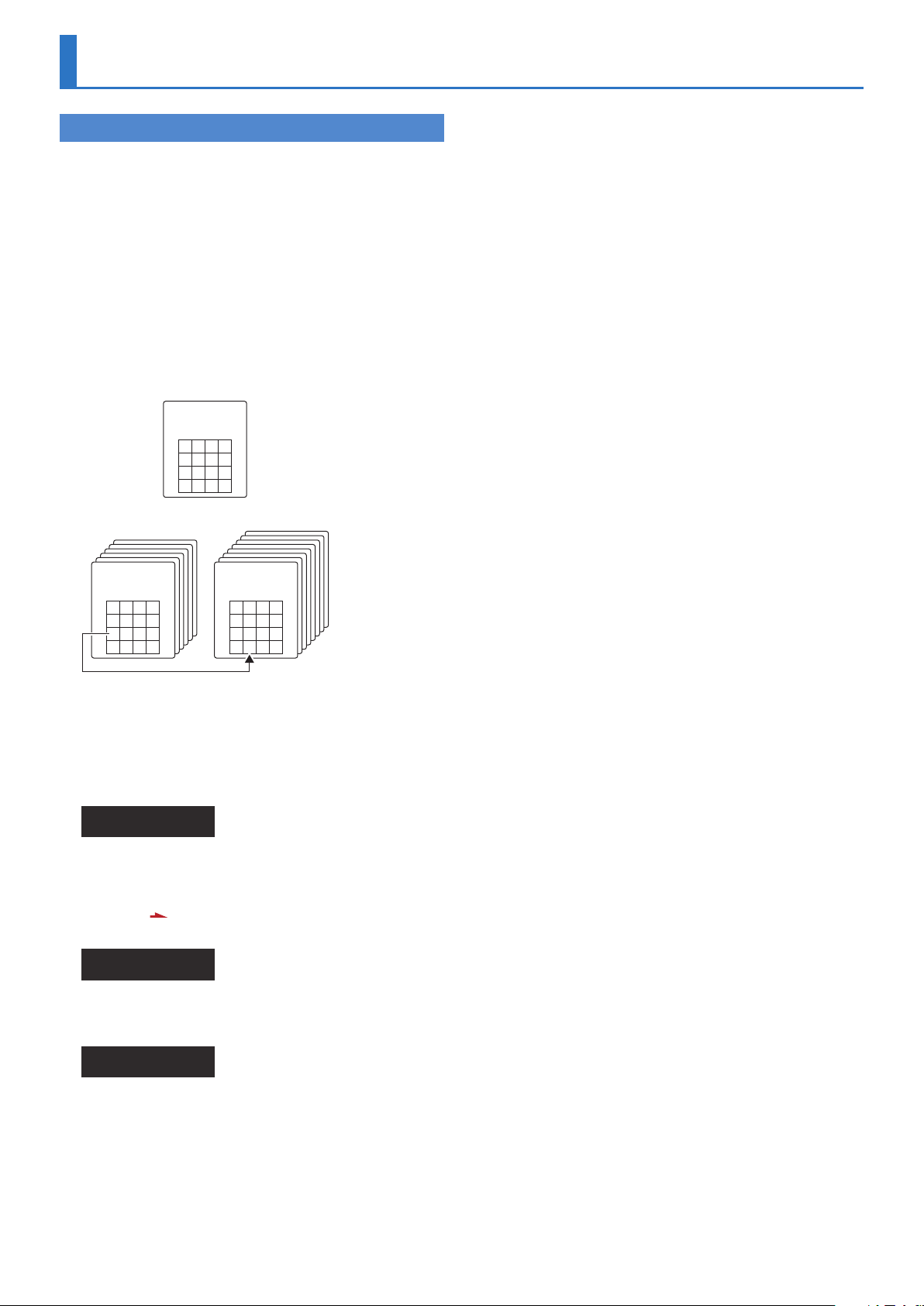
Saving Patches . . . . . . . . . . . . . . . . . . . . . . . . . . . . . . . . . . . . . . . . . . 7
Tone Parameters (Upper/Lower Tone Menu) . . . . . . . . . . . . . 8
Common Parameters (Common) . . . . . . . . . . . . . . . . . . . . . . . 8
Struct (Structure) . . . . . . . . . . . . . . . . . . . . . . . . . . . . . . . . . 8
P-ENV (Pitch Envelope) . . . . . . . . . . . . . . . . . . . . . . . . . . . 8
LFO (Low Frequency Oscillator) . . . . . . . . . . . . . . . . . . . 9
EQ/CHORUS (Equalizer/Chorus) . . . . . . . . . . . . . . . . . . . 10
Partial Parameters (Part-1, Part-2) . . . . . . . . . . . . . . . . . . . . . . . 11
PITCH (WG Pitch) . . . . . . . . . . . . . . . . . . . . . . . . . . . . . . . . . 11
Form (WG Form) . . . . . . . . . . . . . . . . . . . . . . . . . . . . . . . . . 12
TVF (Time Variant Filter) . . . . . . . . . . . . . . . . . . . . . . . . . . 13
TVA (Time Variant Amplier) . . . . . . . . . . . . . . . . . . . . . . 15
Copyright © 2017 ROLAND CORPORATION
01
Key Mode Alteration . . . . . . . . . . . . . . . . . . . . . . . . . . . . . . . . . . . . . 18
Mono Mode, Poly Mode . . . . . . . . . . . . . . . . . . . . . . . . . . . . . . . . 18
SEQUENCER/ARPEGGIATOR . . . . . . . . . . . . . . . . . . . . . . . . . . . . . 19
Transferring Patches To and From the D-50/550 . . . . . . . . . 21
Transferring Patches from the D-50 to the D-05 . . . . . . . . . . 22
Transferring Patches from the D-50/550 to the D-05 22
Sound List . . . . . . . . . . . . . . . . . . . . . . . . . . . . . . . . . . . . . . . . . . . . . . . 23
Preset Patches . . . . . . . . . . . . . . . . . . . . . . . . . . . . . . . . . . . . . . . . . 23
Waveform . . . . . . . . . . . . . . . . . . . . . . . . . . . . . . . . . . . . . . . . . . . . . 29
Parameter List . . . . . . . . . . . . . . . . . . . . . . . . . . . . . . . . . . . . . . . . . . . 31
Patch Factors . . . . . . . . . . . . . . . . . . . . . . . . . . . . . . . . . . . . . . . . . . 31
Tone Parameters . . . . . . . . . . . . . . . . . . . . . . . . . . . . . . . . . . . . . . 31
Common Parameters . . . . . . . . . . . . . . . . . . . . . . . . . . . . . 31
Partial Parameters . . . . . . . . . . . . . . . . . . . . . . . . . . . . . . . . 32
System Parameters . . . . . . . . . . . . . . . . . . . . . . . . . . . . . . . . . . . . 32
MIDI Implementation . . . . . . . . . . . . . . . . . . . . . . . . . . . . . . . . . . . . 33
Page 2
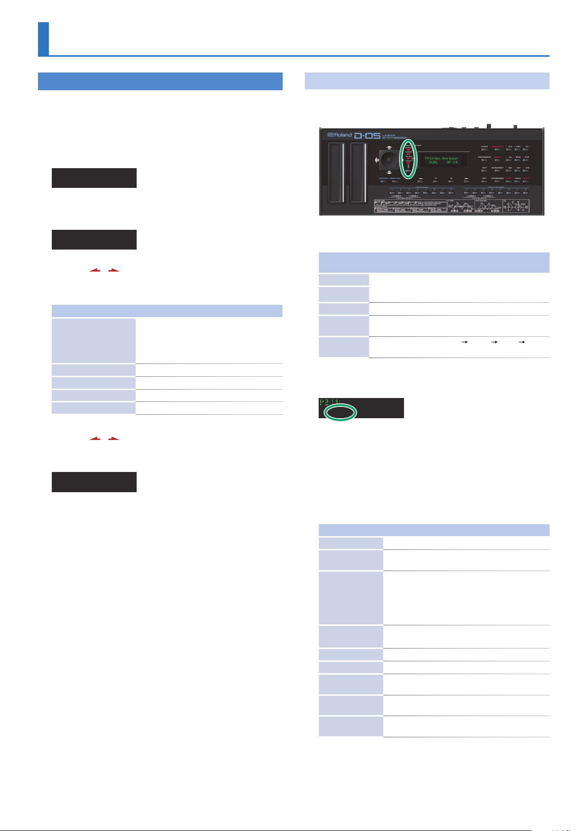
Basic Operation
Basic Operation for Editing
The items that you can edit are grouped into screens. To nd the
item that you want to edit, switch between display screens as
necessary.
1. Make sure that the PATCH TOP screen is shown.
2. Press the [EDIT] button.
Edit Menu
(TnTune)(RtEdit)
3. Press the [F2] (PtEdit) button.
The Patch Edit Menu screen appears.
Patch Edit Menu
(P-Name) (Ctrl)
4. Use the [ ] [ ] buttons to switch pages, and use the
[F1] [F2] buttons to select the item that you want to
edit.
Item Explanation
Rename the patch.
(Patch Name)
P-Name
Ctrl
(Control)
Output Output mode (p. 4)
Chase Chase function (p. 4)
MIDI MIDI functions for each patch (p. 5)
Use the [F1] [F2] buttons to move the cursor
Use the numeric keys to input characters
Press the [EXIT] button to exit the screen
Control functions (p. 3)
Settings Common to All Screens
UPPER/LOWER/VALUE/LOCAL
These buttons switch the function of the joystick.
The function changes each time you press a selection button.
Indicator /
Button
UPPER The up/down direction changes the part balance, and
LOWER
VALUE Enters values, such as during editing.
LOCAL
Select button
Explanation
the left/right direction changes the partial balance of the
selected part.
Enables local editing (a function that lets you use the joystick
to simultaneously edit adjacent items in the display).
Switches in the order of UPPER
LOCAL.
KEY MODE
Neo Horizon
DUAL SP C4
(switching the joystick’s function)
LOWER VALUE
5. Use the [ ] [ ] buttons to switch pages, and use the
[F1] [F2] buttons to select the item that you want to
edit.
Control Edit
Bend 05 AfPB 00
When you press a [F1] [F2] button, the selected parameter blinks.
6. Use the joystick or the [INCREMENT] [DECREMENT]
buttons to edit the setting.
Press the [EXIT] button to return to the Patch Edit Menu screen.
7. Repeat steps 5–6 to make patch factor settings.
8. If you want to save the edited settings, perform the
Write operation.
&
“Saving Patches” (p. 7)
If you don’t want to save, press the [EXIT] button to return to the
PATCH TOP screen. If you return to the PATCH TOP screen without
saving, the colon (:) between the patch number and patch name
blinks, indicates that the patch settings are modied (the patch is
being edited).
* If you select another patch while editing, or turn o the power,
the changes you made to the patch settings are lost.
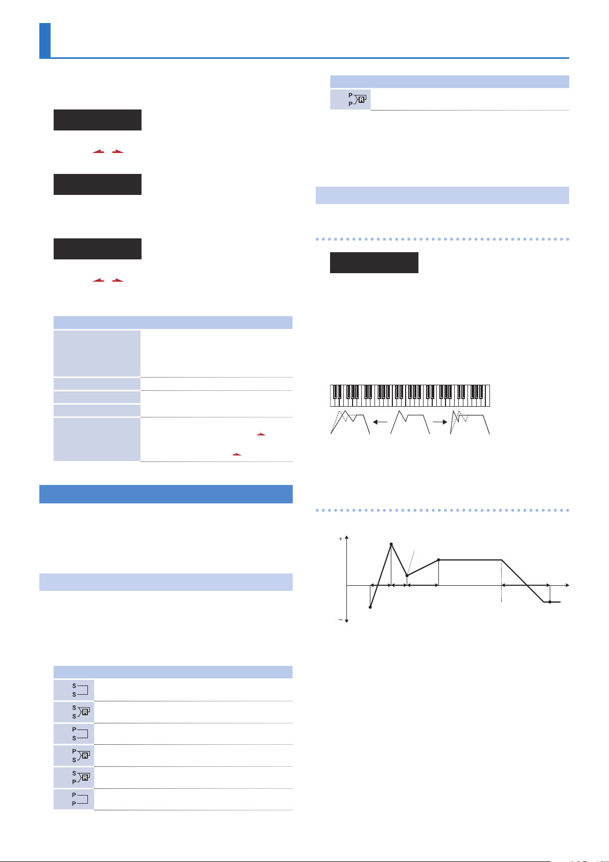
Key Mode refers to the Upper and Lower Tones are played on the
keyboard.
1. In the main screen, press the [F1] button and then use
the [INCREMENT] [DECREMENT] buttons to edit the
parameter.
Value: WHOLE, DUAL, SPLIT, SEP, WHOL-S, DUAL-S, SPL-US, SPL-LS,
SEP-S
Indication Description
WHOLE Upper Tone can be played in 16 voice polyphony
DUAL
SPLIT
SEP
(Separate)
WHOL-S
DUAL-S
SPL-US
SPL-LS
SEP-S
(Whole Solo)
(Dual Solo)
(Split Upper Solo)
(Split Lower Solo)
(Separate Solo)
Both Upper and Lower Tones are played by each key in
8 voices polyphony.
The Split mode divides the keyboard into upper and
lower sections, where two dierent Tones can be played
in 8 voices polyphony. That is, the D-05 works like two 8
voice synthesizers. The Split Point (where the keyboard
is divided into two sections) is shown next to the Key
Mode indication.
The Separate mode lets you control the upper and
lower sections on separate MIDI channels.
The Upper Tone is monophonic.
Both Upper and Lower Tones are monophonic.
The Upper Tone is monophonic, and the Lower Tone is 8
voices polyphonic.
The Lower Tone is monophonic, and the Upper Tone is 8
voices polyphonic.
The Upper Tone and Lower Tone can be controlled on
separate MIDI channels. The Upper Tone is monophonic.
* The way in which the Key Mode aects how the voices play
depends on whether the D-05 is in mono mode or poly mode.
&
“Key Mode Alteration” (p. 18)
2
Page 3
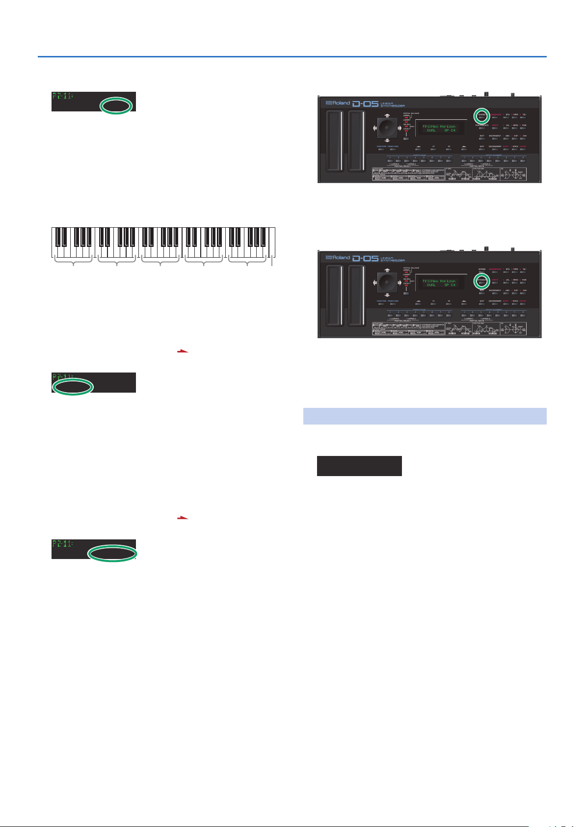
Basic Operation
C7
(middle C)
(Split Point)
SPLIT
Neo Horizon
DUAL SP C4
This species the split point that is used when the KEY MODE
(key mode) is set to SPLIT (split), SPL-US (split upper solo), or SPLLS (split lower solo).
The Split Point can be changed as follows.
1. In the main screen, press the [F2] (SP) button and then
use the [INCREMENT] [DECREMENT] buttons to edit
the parameter.
Value: C2–C7
C2–B2 C3–B3 C4–B4 C5–B5 C6–B6
BALANCE
The volume balance of the Upper and the Lower Tone can be
change.
(Tone Balance)
1. In the main screen, press the [ ] button.
The page changes.
Neo Horizon
Bal 00 Trns 00
CHASE
PORTAMENTO
(Chase Button)
Switches the Chase function (p. 4) on and o.
Value: OFF, ON
(Portamento Button)
Switches the Portamento function on and o. Portamento is
a slide from one pitch to another, and is often used for violin
performance.
Value: OFF, ON
2. Press the [F1] (Bal) button, and then use the
[INCREMENT] [DECREMENT] buttons to edit the
parameter.
Value: 0–100
TRANSPOSE
The pitch range of the keyboard can be transposed (shifted) in
semitone steps.
(Transpose)
1. In the main screen, press the [ ] button.
The page changes.
Neo Horizon
Bal 00 Trns 00
2. Press the [F2] (Trns) button, and then use the
[INCREMENT] [DECREMENT] buttons to edit the
parameter.
If you hold down the [SHIFT] button and use the [INCREMENT]
[DECREMENT] buttons to edit the parameter, the value changes
in steps of one octave (12 semitones).
Value: -36–0–+36
CONTROL
These parameters specify how the control functions aect each
patch.
Control Edit
Bend 05 AfPB 00
Bend
(Bender Range)
This species the available range of pitch change when you
operate pitch bend.
The variable range set here may result dierently depending on
the setting of the Tone Parameter Bender Mode (p. 12).
Value: 0–12
AfterPB
Port
(Aftertouch, Pitch Bender)
This sets the sensitivity of the aftertouch eect on pitch. Higher
values mean higher sensitivity. A Minus setting decreases the
pitch, and a plus setting increases it.
Value: -12–+12
(Portamento Time)
This sets the portamento time from one note to another. Higher
values make the time longer.
Value: 0–100
3
Page 4
Port
Sound Generator Listener
(Portamento Mode)
This selects the Tone that should take on the Portamento
eect. When the Key Mode is Whole , Portamento always works
whichever of the above three modes may be selected.
Value: U, L, UL
Indication Function
U Works on the Upper Tone.
L Works on the Lower Tone.
UL Works on the both Tones.
* Even when Portamento is set to ON, the Portamento ON/OFF
message sent from an external device can change the settings of
Portamento.
Hold
(Hold Mode)
This selects the Tone that on the Pedal Hold eect. When the Key
mode is Whole , Pedal Hold always works whichever of the above
three modes may be selected.
Value: U, L, UL
Indication Function
U Works on the Upper Tone.
L Works on the Lower Tone.
UL Works on the both Tones.
Basic Operation
Rev
(Reverb Type)
Selects one of the 32-reverb types.
Value: 1–32
* A reverb type (any one of types 17–32) from another bank can be
copied to a reverb type (any one of types 17–32) of patch bank
U1–U8.
&
“Copying a Reverb Type” (p. 6)
Rbal
(Reverb Balance)
Sets the volume of the reverb and direct sounds.
Value: 0–100
Indication Function
100
0
Vol
(Total Volume)
The volume of the reverb sound = maximum, the volume
of the direct sound = 0.
The volume of the reverb sound = 0, the volume of the
direct sound = maximum.
Sets the volume of both tones, and therefore adjusts the volume
dierence between Patches.
Value: 0–100
CHASE
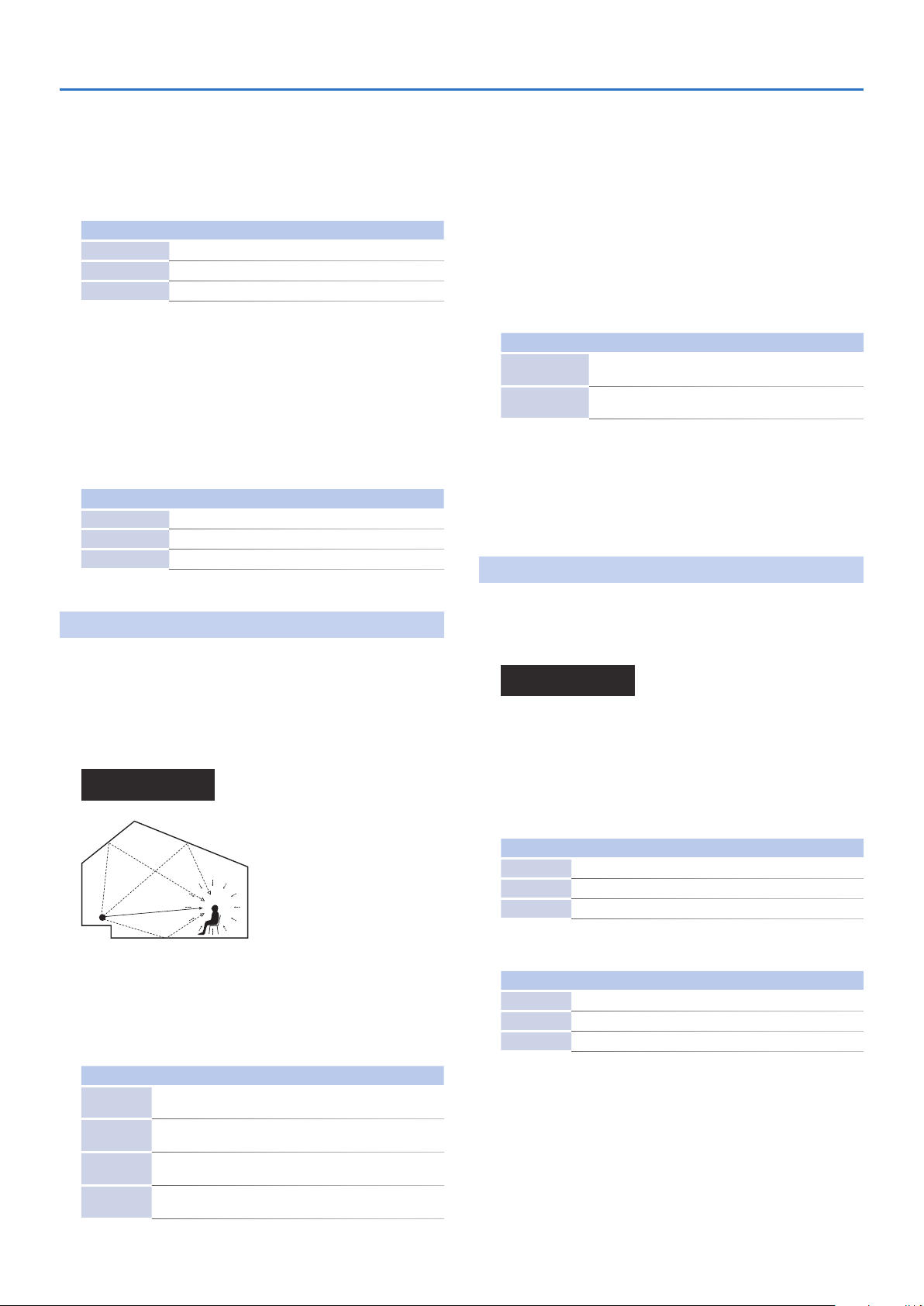
OUTPUT
(Output Mode)
The Output Mode determines how the Tones take on the reverb
eect, and how the Tones appear at the outputs.
A sound reverberated in an acoustic environment consists of three
parts. First, you hear the direct sound as it travels from the source
outward. Next the early reection resounds once, or several time,
from the walls, ceiling ,and oor. Finally, you hear the reverberated
sound as it reects many times in the environment.
Output Mode Edit
Mode 01 Rev 24
Reverb Sound
Direct Sound
Mode
(Output Mode)
Here you can choose one of four modes to specify how the reverb
applied to the two tones is sent from the output.
Value: 01–04
The Chase Play function makes it possible to output the Lower
Tone slightly later than the Upper Tone, which is actually played
on the keyboard. This function, however, is only available in Dual
or Whole Key Mode.
Chase Edit
ModeULU Lev 50
Mode
(Chase Mode)
Sets how tones sound. Depending on the Chase Level and
Velocity , the number of repeats of the delayed sound dier.
Value: UL, ULL, ULU
5
When the Key Mode is Dual
Indication Function
UL The Upper Tone then the Lower Tone is played.
ULL The Upper, then the Lower Tone is repeated.
ULU The Upper, the Lower and the Upper Tone alternate.
5
When the Key Mode is Whole
Indication Function
UL The Upper Tone is played twice.
ULL Upper Tone is repeated.
ULU Upper Tone is repeated.
Indication Function
01
02
03
04
Stereo reverb works on the mixed sound of Upper and Lower
Tones, and id sent out in stereo.
The Mixture of Upper and Lower takes on stereo reverb, and
the direct sound is sent out separately for Upper and Lower.
Only the Upper Tone takes on reverb. Upper and lower Tones
are sent out separately.
Only the Lower Tone takes on reverb, Upper and Lower Tones
are sent out separately.
Lev
(Chase Level)
This adjusts the level of the sound that is heard after a delay
relative to the Upper Tone, which is heard rst. Higher values
produce a higher level.
Value: 0–100
4
Page 5

Time
(Chase Time)
Adjusts the sounding time. Higher value is longer time.
Value: 0–100
TONE TUNE
The relative pitch of the Upper and the Lower Tones can be
separately set. By setting slightly dierent pitches, a detune eect
can be obtained. Also, by lowering the pitch of the Upper Tone,
and raising the pitch of the Lower Tone, the pitches of the Two
Tones can become exactly the same.
Neo Horizon
LKey 00 Ukey 00
LKey
(Key Shift of the Lower Tone)
Allows you to shift the pitch of the Lower Tone in semi-tone steps.
Value: -24–+24 (+/- 2 octave)
UKey
(Key Shift of the Upper Tone)
Allows you to shift the pitch of the Upper Tone in semi-tone steps.
Value: -24–+24 (+/- 2 octave)
Basic Operation
LTun
(Fine Tuning of the Lower Tone)
Allows you to Tune the pitch of the Lower Tone.
Value: -50–+50 (approx. +/- 2 cents)
UTun
(Fine Tuning of the Upper Tone)
Allows you to Tune the pitch of the Upper Tone.
Value: -50–+50 (approx. +/- 2 cents)
MIDI
(MIDI Functions)
You can change the setting of the MIDI Functions included Patch
Factor as follows.
MIDI Edit
TxCH B TxPC OFF
TxCH
(Transmit Channel)
The transmit channel of each Patch can be set to a deferent
number from the basic channel (“Function Menu” 0 “MIDI”
0
“CH” parameter). At B, the channel number is the same as the
Basic Channel.
Value: B (Basic), 1–16
TxPC
(Transmit Program Change Number)
A Program Change number to be transmitted can be set for
each patch individually. At OFF, the Program Change number
preprogrammed in each Patch is transmitted.
Value: OFF, 1–100
SepCH
(Receive Channel in Separate Mode)
A receive MIDI Channel in separate mode can be set for each
Patch individually. At OFF, the receive channel set in MIDI
Functions commonly set for System Function is used (“Function
Menu” 0 “MIDI” 0 “SepCH” parameter).
Value: OFF, 1–16
5
Page 6
Copying a Reverb Type
Copying a Reverb Type
In addition to the patches (64 patches), 16 reverb types (17–32
are also saved to the D-05’s patch banks (P1–P6, U1–U8). Dierent
reverb types 17–32 are saved to each patch bank. The reverb
types you can use vary with the selected patch as described
below.
5 All shared common reverb types (1–16) can be used.
5 The reverb types 17–32 in individual banks can be used only
with the patches (64 patches) contained in that bank.
5 Reverb types from a bank other than the internal banks (any
from 1 through 32) can be copied to a reverb type in the
internal banks (any from 17 through 32).
5 This is convenient when, for example, you want to use Reverb
Type 25 (Gate Reverb) from the Patch Bank P1 as Reverb Type
30 in the Patch Bank U1.
Common
Reverb Type
(NOT rewritable)
1 2 3 4
5 6 7 8
9 10 11 12
13 14 15 16
User BankPreset Bank
P1
Reverb Type
(NOT rewritable)
17 18 19 20
21 22 23 24
25 26 27 28
29 30 31 32
* Reverb Types (17–32) are transferred simultaneously with patch
data when patch data is transferred from the D-50 to the D-05
(bulk loaded) or from the D-05 to the D-50 (bulk dumped).
U1
Reverb Type
(rewritable)
17 18 19 20
21 22 23 24
25 26 27 28
29 30 31 32
1. Hold down the [SHIFT] button and press the [WRITE]
button.
The Reverb Write screen appears.
Reverb Write
To: U8-24
2. Use the [F1] [F2] buttons and the [INCREMENT]
[DECREMENT] buttons to select the copy-destination.
3. Press the [ ] button.
A conrmation message appears.
Reverb Write?
[EXIT]:N [ENT]:Y
If you decide to cancel, press the [EXIT] button.
4. Press the [ENTER] button.
Completed.
When saving is nished, the destination indicates Completed.
6
Page 7

Saving Patches
1. Press the [WRITE] button.
The WRITE screen appears.
(Patch Name)
To: U2-11
2. Use the [INCREMENT] [DECREMENT] buttons and the
PATCH BANK [1]–[8] and NUMBER [1]–[8] buttons to
select the save-destination.
3. Press the [ ] button.
A conrmation message appears.
Patch Write?
[EXIT]:N [ENT]:Y
4. Press the [ENTER] button.
Completed.
When saving is nished, the destination indicates Completed.
7
Page 8
Tone Parameters (Upper/Lower Tone Menu)
(Key On)
Point 1
Pitch 0
1. Make sure that the PATCH TOP screen is shown.
2. Press the [EDIT] button.
Edit Menu
(TnTune)(RtEdit)
3. Use the [ ] [ ] buttons to switch the page so that
(L-Tone) (U-Tone) is displayed.
Edit Menu
(L-Tone)(U-Tone)
4. Use the [F1] (lower) [F2] (upper) buttons to select the
tone that you want to edit.
Upper Tone Menu
(T-Name)(Common)
5. Use the [ ] [ ] buttons to switch pages, and use the
[F1] [F2] buttons to select the item that you want to
edit.
Item Explanation
Edits the tone name.
(Tone Name)
T-Name
Common Common parameters
Part-1
(Partial 1 Parameter)
(Partial 2 Parameter)
Part-2
T-Copy
(Tone Copy)
Use the [F1] [F2] buttons to move the cursor
Use the numbers to enter characters
Press the [EXIT] button to exit the screen
Partial parameters
Copies a tone.
Select the copy-source, and press the [
button
Assign a name, and press the [
]
] button
Number Partial 1 Partial 2 Combination of two Partials
07
P P
Mixture of Partial 1 and ringmodulation.
S: Synthesizer Sound Generator
P: PCM Sound Generator
R: Ring Modulator
P-ENV
(Pitch Envelope)
P-ENV Edit
U:P-Env Edit
Velo 00 TKF 00
Velo
(Envelope)
(Velocity Range)
Sets the maximum eect of the velocity that controls the pitch of
the P-ENV. At higher values, the keyboard velocity has a greater,
eect on the envelope.
Value: 0–2
TKF
(Keyfollow (Time))
Sets the time of the P-ENV depending on the key played. Higher
values change the time more drastically.
Value: 0–4
Common Parameters
&
“Struct (Structure)” (p. 8)
&
“P-ENV (Pitch Envelope)” (p. 8)
&
“LFO (Low Frequency Oscillator)” (p. 9)
&
“EQ/CHORUS (Equalizer/Chorus)” (p. 10)
Struct
(Structure)
Str
(Structure Number)
(Common)
Selects one of seven ways in which the partials are combined and
used.
Value: 01–07
Number Partial 1 Partial 2 Combination of two Partials
01
02
03
04
05
06
S S Mixture of Partial 1 and partial 2.
S S
P S Mixture of Partial 1 and partial 2.
P S
S P
P P Mixture of Partial 1 and partial 2.
Mixture of Partial 1 and ringmodulation.
Mixture of Partial 1 and ringmodulation.
Mixture of Partial 1 and ringmodulation
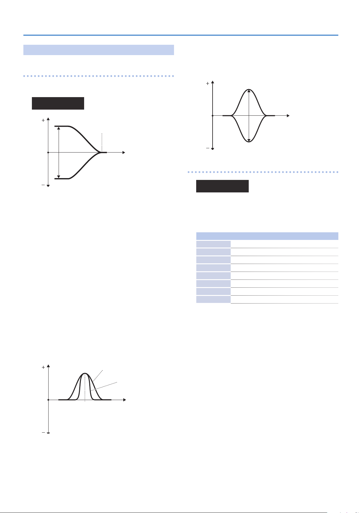
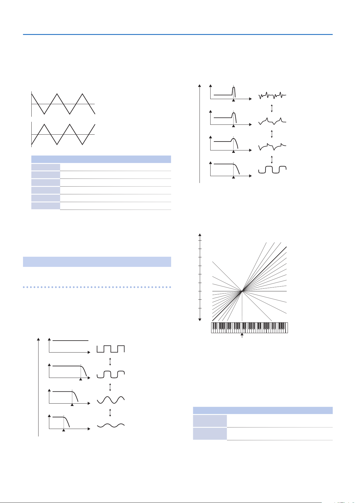
P-ENV Time
(Pitch Envelope Time)
The envelope curve is determined by times and levels.
Point 2
Point 3
T1
(Time 1)
L0
Point 0
L1
L3
T1
T2 T3 T4
SusL
(Key O) Point 4
Sets the time needed from point 0 (the moment the key is
pressed) to point 1.
Value: 0–50
T2
(Time 2)
Sets the time needed from point 1 to point 2.
Value: 0–50
T3
(Time 3)
Sets the time needed from point 2 to point 3.
Value: 0–50
EndL
8
Page 9
T4
(Time 4)
Sets the time needed from the moment the key is released to
point 4.
Value: 0–50
Tone Parameters (Upper/Lower Tone Menu)
Aftr
(Pitch Aftertouch Modulation)
This sets the sensitivity of the vibrato depth controlled by
aftertouch. Higher values deepen the vibrato eect.
Value: 0–100
P-ENV Level Edit
L0
(Level 0)
Sets the pitch created the moment a key is pressed.
Value: -50–+50
L1
(Level 1)
Sets the pitch of the point 1.
Value: -50–+50
L2
(Level 2)
Sets the pitch of the point 2.
Value: -50–+50
SusL
(Sustain level)
Sets the pitch of the point 3.
Value: -50–+50
EndL
(End Level)
Sets the pitch of the point 4.
Value: -50–+50
* If the Levels of two adjacent points are set to similar values, the
time between these two points may prove to be shorter than
what is actually set, or even zero.
* The maximum variable range of each level will depend on the
Velocity Range in P-ENV. (p. 8)
Velocity Range Level Range
0
1
2
Pitch Mod
Depending on how the LFO in WG Mod (p. 11) is set, the vibrato
set here may have no eect at all.
U:P-Mod Edit
LFOD 02
+50 +1 octave
-50 -1 octave
+50 +1.5 octave
-50 -1.5 octave
+50 +2 octave
-50 -2 octave
(Pitch Modulation)
LFO
(Low Frequency Oscillator)
The parameters of LFO-2 and LFO-3 can be set like LFO-1, except
for a few parameters.
U:LFO1 Edit
WaveTRI Rate 74
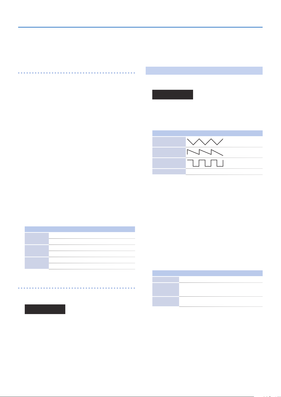
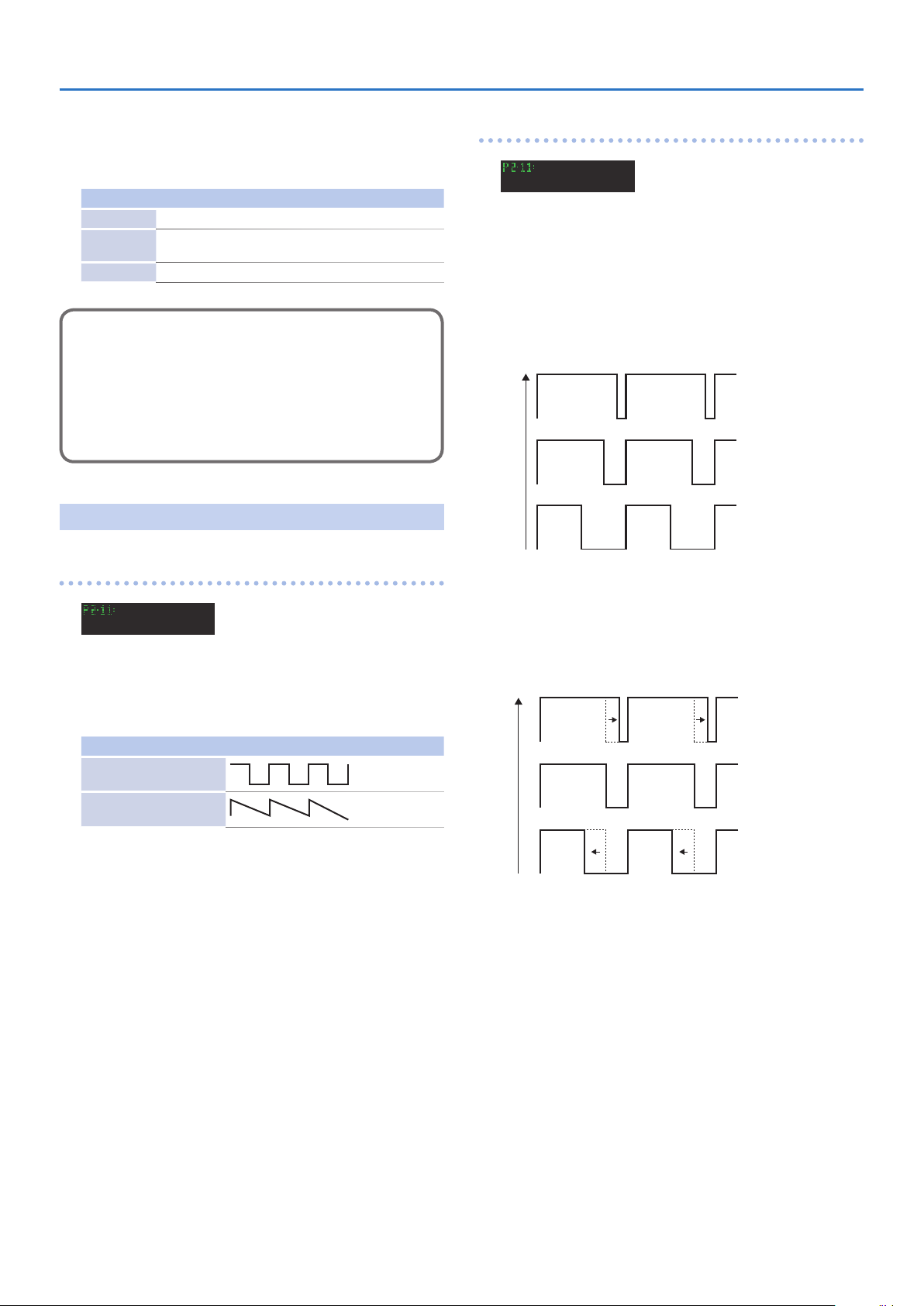
Wave
(LFO Waveform)
Selects the LFO waveform.
Value: TRI, SAW, SQU, RND
Indication Waveform
TRI
(Triangle wave)
SAW
(Sawtooth)
SQU
(Square wave)
RND
(Random)
Rate
(LFO Rate)
Sets the rate (frequency) of the LFO. Higher values quicken the
rate.
Value: 0–100
Dely
(LFO Delay Time)
This sets the time needed for the LFO to appear, from the moment
a key is pressed. Higher values increase the delay time.
Value: 0–100
Waveform changes randomly.
Sync
Selects the timing of the LFO oscillation as follows. For LFO-2 and
LFO-3, KEY cannot be selected.
Value: OFF, ON, KEY
Indication Function
OFF LFO does not sync to the keyboard.
ON
KEY
When a key is played after all keys have been released,
the LFO begins its wave generating process from the
beginning.
LFO begins its wave generation from the beginning each
time a new key is played.
LFOD
(LFO Depth)
Sets the depth of LFO-1, that controls the WG pitch. Higher values
deepen the eect.
Value: 0–100
Levr
(Pitch Lever Modulation)
Sets the sensitivity of the vibrato depth controlled by the bender
lever. Higher values deepen the eect.
Value: 0–100
9
Page 10
EQ/CHORUS
Frequency
Level 0
Frequency
Level 0
HQ is low.
Frequency
Level 0
EQ Edit
(Equalizer)
(Equalizer/Chorus)
Tone Parameters (Upper/Lower Tone Menu)
Hg
(High Gain)
Sets the gain of the Hf frequency.
“+” settings raise the gain and “-” settings lower it.
Value: -12–+12 dB
In the equalizer section, the frequency characteristic of the sound
can be modied.
U:EQ Edit
Lf 300 Lg +01
LowFreq
LowGain
Lf
(Low Frequency)
Sets the frequency where the gain is altered in the low to middle
range.
Value: 63, 75, 88, 105, 125, 150, 175, 210, 250, 300, 350, 420, 500,
600, 700, 840 Hz
Lg
(Low Gain)
Sets the gain of the lower frequencies.
“+” settings raise the gain, and “-” settings lower it.
Value: -12–+12 dB
Hf
(High Frequency)
Sets the frequency where the gain is altered in the middle to high
range.
Value: 250, 300, 350, 420, 500, 600, 700, 840 Hz, 1.0, 1.2, 1.4, 1.7,
2.0, 2.4, 2.8, 3.4, 4.0, 4.8, 5.7, 6.7, 8.0, 9.5 kHz
HQ
(High Q)
Sets the width of the frequency band where the gain is boosted
or cut. With a higher value, the frequency band is narrower, and
vice versa.
Value: 0.3, 0.5, 0.7, 1.0, 1.4, 2.0, 3.0, 4.2, 6.0
HQ is Height.
HiFreq
HiGain
Chorus Edit
U:Chorus Edit
Type 02 Rate 25
Type
Selects one of the 8 basic chorus eects.
Value: 01–08
Indication Type
01 Chorus 1
02 Chorus 2
03 Flanger 1
04 Flanger 2
05 Feedback Chorus
06 Tremolo
07 Chorus Tremolo
08 Dimension
Rate
(Chorus Rate)
Sets the rate of the chorus eect. Higher values quicken the rate.
Value: 0–100
Dpth
Sets the depth of the chorus eect. Higher values deepen the
eect.
Value: 0–100
(Chorus)
(Chorus Type)
(Chorus Depth)
HiFreq
10
Bal
(Chorus Balance)
This sets the volume balance of the chorus of the chorus sound
and normal sound.
Value: 0–100
Page 11
Partial Parameters
s2
s1
+3
Pitch
Middle C (C4)
(Part-1, Part-2)
Restriction of the available parameters caused
by Structure
Depending on what Structure is used, the available
parameters may be dierent.
1. Some parameters included in a Partial that uses
a PCM sound generator are invalid.
2. With Ring Modulation, some parameters in
Partial 2 will automatically become the same as
for Partial 1. Therefore, the values shown in the
display are irrelevant with the actual values.
&
“PITCH (WG Pitch)” (p. 11)
&
“Form (WG Form)” (p. 12)
&
“TVF (Time Variant Filter)” (p. 13)
&
“TVA (Time Variant Amplier)” (p. 15)
&
“*Init*” (Initialize)
Tone Parameters (Upper/Lower Tone Menu)
KF
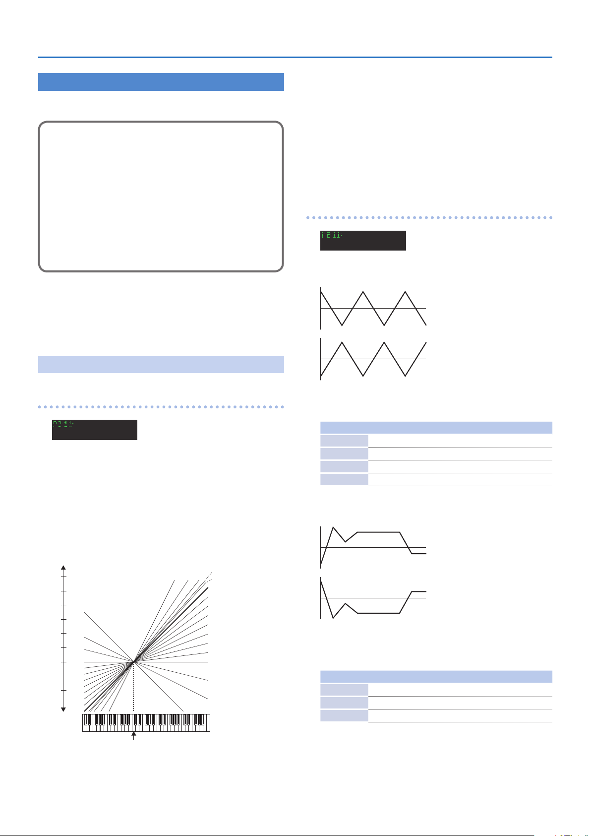
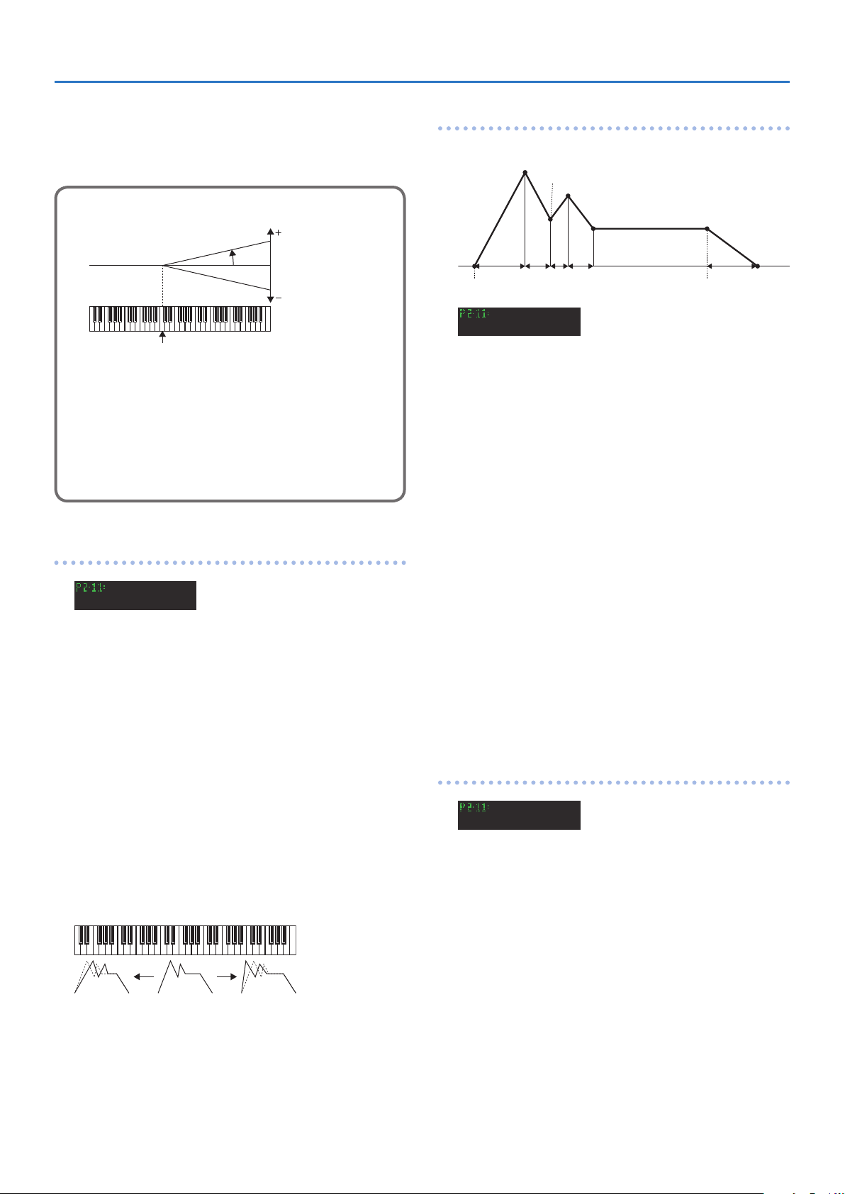
(Keyfollow (pitch))
Usually, the keyboard to a synthesizer assigns a semi-tone to each
key. This parameter can change the pitch ratio as show below. The
value represents how many octaves are changed over 12 keys.
Value: -1, -1/2, -1/4, 0, 1/8, 1/4, 3/8, 1/2, 5/8, 3/4, 7/8, 1, 5/4, 3/2, 2,
s1, s2
* s1 or s2 may be selected for slightly stretching octaves.
s1: Pitch 1 cent higher than one octave.
s2: Pitch 5 cents higher than one octave.
WG Mod
LFO
(Modulation)
S3 WG Mod
LFO OFF ENV (+)
(LFO Mode)
Normal
PITCH
(WG Pitch)
WG Pitch
Cors
Sets the standard pitch of a Partial in semi-tone steps. The
standard pitch is the pitch at C4 (middle C) key.
Value: C1–C7
Fine
Makes a ne adjustment to the standard pitch.
Value: -50–+50
(Pitch)
S3 WG Pitch
CorsC5 Fine 00
(Pitch Coarse)
(Pitch Fine)
(Octave)
2
-1
1
-1/2
-1/4
0
-1
5/4
3/2
2
1
7/8
3/4
5/8
1/2
3/8
1/4
1/8
0
Selects one of the following four vibrato modes.
Value: OFF, (+), (-), A&L
Indication Function
OFF No vibrato is obtained.
(+) Vibrato is on.
(-) Vibrato is on but inverted.
A&L Vibrato can be obtained only by Aftertouch and Bender Lever.
ENV
(P-ENV Mode)
Selects one of the following three modes, determining how the
pitch is controlled by P-ENV.
Value: OFF, (+), (-)
Indication Function
OFF No alteration.
(+) Pitch changes with the set P-ENV curve.
(-) Pitch changes with the P-ENV curve inverted.
“-” is selected.
“+” is selected.
“-” is selected.
11
Page 12
Bend
97%
50%
0
100
+7
(Bender Mode)
Selects how the pitch is controlled by the bender lever as follows.
Value: OFF, KF, Norm
Indication Function
OFF No pitch alteration by moving the lever right or the left.
KF
Norm Pitch changes within the Bender range, set in Patch Factors.
Pitch changes within the Bender range, set in Patch Factors,
plus Keyfollow (Pitch) of WG.
Bender Mode Example:
5 If the Bender range (p. 3) is set to 12 (1 octave), and the
Keyfollow (Pitch) (p. 11) of WG is set to 2, the maximum
pitch change caused by moving the Bender Lever is 2
octaves.
5 When the Keyfollow (Pitch) (p. 11) of WG is set to zero,
there is no pitch change caused by the Bender lever.
Form
(WG Form)
Tone Parameters (Upper/Lower Tone Menu)
WG PW
PW
(Pulse Width)
S3 WG PW
PW 00 Velo 00
(Pulse Width)
A square waveform has exactly the same width, up and down but
a Pulse waveform has dierent widths. The ratio of upper width
to lower is called pulse width. Depending on the set pulse width
value, the harmonic content of the sound changes greatly.
Value: 0–100
* When a sawtooth is selected with WG Waveform , pulse width
50% raises the pitch by an octave.
50
WG Form
Wave
Selects the waveform of the synthesizer sound generator.
Value: SQU, SAW
* A sawtooth waveform is produced by processing a square
PCM
This selects one of the 100 dierent sampled waves of the PCM
sound generator.
&
Value: 1–100
(Waveform)
S3 WG Form
WaveSAW
(Waveform)
Indication Waveform
SQU
(Square wave)
SAW
(Sawtooth)
Waveform at the TVF, that is, all the waveform are square at WG
even when a sawtooth is selected.
(PCM Wave Number)
“Waveform” (p. 29)
Velo
(Velocity Range)
Sets the sensitivity of the velocity that controls the pulse width.
With “-” values, the pulse width becomes smaller by playing the
keyboard harder, and with “+” values, the pulse width becomes
wider by playing the keyboard harder.
Value: -7–+7
0
-7
Aftr
(Aftertouch Range)
Sets the sensitivity of the aftertouch that controls the pulse width.
With “-” values, the pulse width becomes smaller with stronger
aftertouch, and with “+” values, the pulse width becomes wider
with stronger aftertouch.
Value: -7–+7
12
Page 13
LFO
Cuto Point Frequency
0
100
30
1/8
1/4
3/8
1/2
5/8
3/4
7/8
+3
Pitch
Middle C (C4)
(LFO Select)
Pulse Width Modulation (PWM) means changing the pulse width
periodically.
LFO Select decides which of the LFO’s is to be used for modulating
the pulse width.
Value: +1, -1, +2, -2, +3, -3
Tone Parameters (Upper/Lower Tone Menu)
Reso
(Resonance)
Boosts the cuto point. As you increase the value, specic
harmonics are emphasized and the sound will become more
unusual, more electronic in nature.
Value: 0–30
Level
Positive Phase (+)
Negative Phase (-)
Indication LFO
+1 LFO-1 (+)
-1 LFO-1 (-)
+2 LFO-2 (+)
-2 LFO-2 (-)
+3 LFO-3 (+)
-3 LFO-3 (-)
LFOD
(LFO Depth)
(Phase)
This sets the depth of the PWM. Higher values Deepen the eect.
Value: 0–100
TVF
(Time Variant Filter)
TVF
Freq
(Cuto Frequency)
Sets the cuto point of the TVF. As you lower the value, higher
frequencies are removed and the waveform gradually become an
approximation of a sine wave, then the sound will nally fade out.
Value: 0–100
Cuto Point Frequency
Level
Value
KF
(Keyfollow (Cuto Point))
Cuto Point Frequency
Level
Cuto Point Frequency
Level
Keyfollow can change the cuto point depending on the key
played. Just like the Keyfollow of WG pitch, the value represents
how many octaves change over 12 keys.
Value: -1, -1/2, -1/4, 0, 1/8, 1/4, 3/8, 1/2, 5/8, 3/4, 7/8, 1, 5/4, 3/2, 2
5/4
3/2
2
1
0
-1
2
1
0
(Octave)
-1
-1/2
-1/4
Level
Value
Frequency
Level
Cuto Point Frequency
Level
BP
(Bias Point)
You can add a further change (= bias level) to the Keyfollow curve,
and set the range (bias direction) where the bias level is valid. The
bias range is where the bias level is valid on the keyboard. It can
be set with the bias point (where the bias range begins) and bias
direction ( < or > ).
Value: <A1–<C7, >A1–>C7
Cuto Point Frequency
Level
Display Example Example Function
>C4
<C4
The bias level is only valid on the keyboard above the C4
key.
The bias level is only valid on the keyboard below the C4
key.
13
Page 14
BLvl
Middle C (C4)
Value
Point 1
Key On Key O
(Bias Level)
The bias level can be set. “+” values raise the curve, and “-” value
lower the curve.
Value: -7–+7
Keyfollow Adjustment
Tone Parameters (Upper/Lower Tone Menu)
TVF ENV Time
An envelope curve is determined by times and levels.
(TVF Envelope Time)
Point 2
Point 3
Point 4
Angle
0
The curve in the picture represents the Keyfollow value with
the bias level added.
This means that if the keyfollow slope is dierent, the actual
slope will dier even if the value of the slope to be biased is
the same.
TVF Keyfollow (Cuto Point): 0
Bias Direction: >C4
TVF ENV
Dpth
Velo
DKF
TKF
(TVF Envelope)
S3 TVF ENV
Depth100 Velo 00
(ENV Depth)
Sets the depth of the TVF ENV modulation that changes the TVF
cuto Point. Higher values deepen the eect.
Value: 0–100
(Velocity Range)
Sets the sensitivity of the velocity than controls the depth of the
TVF ENV. At higher values, the eect is deeper by playing harder.
Value: 0–100
(Keyfollow (Depth))
This can change the TVF ENV depth depending on the key played.
Higher values change the depth more drastically.
Value: 0–4
(Keyfollow (Time))
SusLL3L2L1
T1 T2 T3 T4 T5
S3 TVF ENV
T1 00 T2 00
T1
(Time 1)
Sets the time needs to reach point 1 from the moment the key is
pressed.
Value: 0–100
T2
(Time 2)
Sets the time needed to reach point 2 from point 1.
Value: 0–100
T3
(Time 3)
Sets the time needed to reach point 3 from point 2.
Value: 0–100
T4
(Time 4)
Sets the time needed to reach point 4 from point 3.
Value: 0–100
T5
(Time 5)
Sets the time needed to reach point 5 from the moment the key
is released.
Value: 0–100
TVF ENV Level
L1100 L2100
L1
(Level 1)
Sets the of point 1.
Value: 0–100
(TVF Envelope Level)
S3 TVF ENV
Point 5
EndL
This can change the time of the TVF ENV depending on the key
played. Higher values change the time more drastically.
Value: 0–4
14
L2
(Level 2)
Sets the level of point 2.
Value: 0–100
L3
(Level 3)
Sets the level of point 3.
Value: 0–100
SusL
(Sustain level)
This sets the level of point 4.
Value: 0–100
Page 15

EndL
C6
Value
(End Level)
To lower the level after releasing the key, set this to 0, and to raise
the level, set it to 100.
Value: 0, 100
* The End Level is retained until you release and play the key again.
* If the Levels of two adjacent points are set to similar values, the
time between these two points may prove to be shorter than
what is actually set, or even zero.
TVF MOD
LFO
Selects the LFO that changes cuto point periodically (creating
growl eects).
Value: +1, -1, +2, -2, +3, -3
(TVF Modulation)
S3 TVF Mod
LFO +1 LFOD 00
(LFO Select)
Indication LFO
+1 LFO-1 (+)
-1 LFO-1 (-)
+2 LFO-2 (+)
-2 LFO-2 (-)
+3 LFO-3 (+)
-3 LFO-3 (-)
(Phase)
Positive Phase (+)
Negative Phase (-)
Tone Parameters (Upper/Lower Tone Menu)
TVA
(Time Variant Amplier)
TVA
S3 TVA
Levl 80 Velo+10
Levl
(Level)
Sets the volume of a Partial. Higher values may cause sound
distortion. If so, lower the value. Even when the Level is set to zero
here, the sound may not be completely muted if the TVA ENV
curve is high.
Value: 0–100
Velo
(Velocity Range)
Sets the sensitivity of the velocity that controls the volume of the
sound. “-” values lower the level by harder playing, and “+” values
raise the level by harder playing.
Value: -50–+50
BP
(Bias Point)
You can change the overall volume of the keyboard (= bias level)
from the set level, and set the range (bias direction) where the
bias level is valid.
This bias range is where the bias level is valid on the keyboard. It
can be set with the bias point (Where he bias range begins) and
bias direction ( < or > ).
Value: <A1–<C7, >A1–>C7
Display Example Function Example
>C4
<C4
The bias level is only valid on the keyboard above the C4
key.
The bias level is only valid on the keyboard below the C4
key.
LFOD
(LFO Depth)
Sets the depth of a growl eect. Higher values deepen the eect.
Value: 0–100
Aftr
(Aftertouch Range)
Sets the sensitivity of the aftertouch that controls the cuto point.
“-” values lower the cuto point by stronger Aftertouch, and “+”
values raise it.
Value: -7–+7
BLvl
(Bias Level)
The curve ( bias level ) can be set. Lower values make the curve
steeper.
Value: -12–0
Volume Adjustment
0
Angle
Bias Point: >C6
15
Page 16

TVA ENV Time
Point 1
Key On Key O
An envelope curve is determined by times and levels.
(TVA Envelop Time)
Point 2
Point 3
Point 4
SusLL3L2L1
T1 T2 T3 T4 T5
Point 5
EndL
Tone Parameters (Upper/Lower Tone Menu)
EndL
(End Level)
To lower the level after releasing the key, set this to 0, and to raise
the level, set it to 100.
Value: 0, 100
* The End Level remains until the key is released and played again.
That is, at a value of 100, the sound remains. However, the PMC
Sound Generator’s One-shot sounds do not remain even when
set to 100.
* If the levels of two adjacent points are set to similar values, the
time between these two points may prove to be shorter than
what is actually set, or even zero.
S3 TVA ENV
T1 00 T2 00
T1
(Time 1)
Sets the time needed to reach point 1 from the moment the key
is pressed.
Value: 0–100
T2
(Time 2)
Sets the time needed to reach point 2 from point 1.
Value: 0–100
T3
(Time 3)
Sets the time needed to reach point 3 from point 2.
Value: 0–100
T4
(Time 4)
Sets the time needed to reach point 4 from point 3.
Value: 0–100
T5
(Time 5)
Sets the time needed to reach point 5 from the moment the key
is released.
Value: 0–100
TVA ENV
Velo
TKF
(Envelope)
S3 TVA ENV
Velo 00 TKF 00
(Velocity Follow (Time 1))
Sets the sensitivity of the velocity than controls the Time 1 of the
TVA ENV. Increasing the sensitivity shortens Time 1, by stronger
playing.
Value: 0–4
(Keyfollow (Time))
This can change the time o the TVA ENV depending on the key
played. 0 to 4 are valid. Higher values change the time more
drastically.
Value: 0–4
TVA ENV Level
S3 TVA ENV
L1100 L2100
L1
(Level 1)
Sets the level of point 1.
Value: 0–100
L2
(Level 2)
Sets the level of point 2.
Value: 0–100
L3
(Level 3)
Sets the level of point 3.
Value: 0–100
SusL
(Sustain level)
Sets the level of point 4.
Value: 0–100
(Level)
16
Page 17

Tone Parameters (Upper/Lower Tone Menu)
TVA MOD
LFO
Selects the LFO that changes the volume periodically
(tremolo eects) .
Value: +1, -1, +2, -2, +3, -3
(TVA Modulation)
S3 TVA Mod
LFO +1 LFOD 00
(LFO Select)
Indication LFO
+1 LFO-1 (+)
-1 LFO-1 (-)
+2 LFO-2 (+)
-2 LFO-2 (-)
+3 LFO-3 (+)
-3 LFO-3 (-)
(phase)
Positive Phase (+)
Negative Phase (-)
LFOD
(LFO Depth)
Sets the depth of the tremolo eect. Higher values deepen the
eect.
Value: 0–100
Aftr
(Aftertouch Range)
Sets the sensitivity of the aftertouch that controls the volume.
“-” values lower the volume by stronger aftertouch. And “+”
values increase the volume by stronger aftertouch.
Value: -7–+7
17
Page 18

Key Mode Alteration
The way in which the Key Mode (p. 2) aects how notes are
sounded diers depending on whether you’re using the D-05 in
mono mode or in poly mode.
Mono Mode, Poly Mode
When you’re using the D-05 from an external MIDI device, the D-05
can receive MIDI channels in the following two ways.
The D-05 can be used in one or the other of these two modes.
Name Function
Allows the control of more than one Key message on one
Poly Mode
Mono Mode
Select Poly or Mono mode depending on the type of Mode
Message sent from the external MIDI device.
When Mono mode messages are received by the D-05, the
messages can now be received on a channel group (= eight
consecutive MIDI channels, the basic channel being the lowest
number).
* The Mono mode of the D-05 allows it to receive only the note and
bender messages for each channel, therefore it is NOT possible to
set a dierent sound for each note separately.
channel at a time.
The D-05 is 16 or 8 voices polyphonic (depending on the
patch used). So the Poly Mode can be used the D-05 is
controlled by a keyboard or sequencer.
Allows only one MIDI massage on one channel. The D-05 is
8 voices polyphonic using 8 MIDI channels. The Mono mode
is ideal for a MIDI Guitar System (GR-33, GR-20, etc.) hat has
Mono mode, and transmits the messages of each string
separately on a dierent channel. In the other words, Mono
mode makes it possible to reproduce guitar sounds without
spoiling the natural characteristics of the instrument.
18
Page 19

SEQUENCER/ARPEGGIATOR
When you want to use the sequencer, press the [SEQUENCER]
button.
The PATCH BANK [1]–[8] buttons and NUMBER [1]–[8] buttons
indicate the status of each step in the step display area that’s
selected (STEP: 1–16, 17–32, 33–48, 49–64).
SEQ MAIN
Tempo
(sequencer screen)
Steps shown on the
panel (step buttons)
Ì:120 1-16* Play (PtnSel)
Shown on
the panel
(step buttons)
You can change the tempo when the tempo is displayed and no
item is selected by the [F1] [F2] buttons.
Use the [
shown.
Press a [1]–[16] button to enable step input. The screen shows
step information.
STEP INFO
Currently
playing
] [ ] buttons to change the range of steps that are
Step 1 Gate 80
C4 D#4 G4 ---
Outside the STEP
LENGTH range
Play/Stop
Plays/stops the selected pattern.
Sh
(Shue)
Species the amount of rhythm “bounce” (shue).
Value: -90–0–+90
Gate
(Gate)
Species the note duration for one step.
Value: 1–100
O
(O Step Mode)
Species whether muted steps will be treated as rests or skipped
(O Step Mode).
* This setting is not saved in the pattern.
Value: REST, SKIP
Indication Explanation
REST Rest
SKIP Skip
Ord
(Step Order)
Species the playback order of the steps.
* This setting is not saved in the pattern.
Value: , , , , RND
Indication Explanation
Play forward from the rst step.
Play backward from the last step.
Play forward from the rst step, and then play backward
from the last step.
Play with even-numbered and odd-numbered steps
inverted.
RND Play steps randomly.
(PtnSel) Pattern Select
Accesses the pattern select screen.
SEQ PRM
Len
Scal
(sequencer parameter)
In the SEQ MAIN screen, hold down the [SHIFT] button and press
the [F2] button to access the SEQ PRM screen.
(Length)
Species the pattern length (number of steps).
Value: 1–64
(Scale)
Species the note value of one step.
Value: 4, 8, 16, 32, 4T, 8T, 16T
Indication Explanation
4 Quarter note
8 Eighth note
16 Sixteenth note
32 Thirty-second note
4T Quarter-note triplet
8T Eighth note triplet
16T Sixteenth note triplet
S. Stp
(Start Step)
By specifying the start step, you can make playback start from a step that’s mid-
way through the pattern. Steps earlier than this step are not played.
* This setting is not saved in the pattern.
1. Hold down the [F1] button and use the [INCREMENT]
[DECREMENT] buttons to edit the value.
Value: -, 1–64
Indication Explanation
- Not specied
1–64 First step
E.STP
(End Step)
By specifying the last step, you can make a step that’s mid-way
through the pattern be treated as though it were the last step.
Steps later than this step are not played.
* This setting is not saved in the pattern.
1. Hold down the [F2] button and use the [INCREMENT]
[DECREMENT] buttons to edit the value.
Value: -, 1–64
Indication Explanation
- Not specied
1–64 Last step
19
Page 20

SEQUENCER/ARPEGGIATOR
* Clear *
Clears the pattern.
PATTERN WRITE
While the sequencer screen is displayed, press the [WRITE]
button.
(Pattern name)
Edits the pattern name.
[F1] [F2] buttons: Move the cursor
Tempo
Species the tempo.
Value: OFF, 40–300
Indication Explanation
OFF The tempo is not stored.
40–300 The pattern is stored with the specied tempo.
Shue
Species the amount of rhythm “bounce” (shue).
Value: OFF, -90–0–90
Indication Explanation
OFF The amount of shue is not stored.
-90–0–90 The pattern is stored with the specied amount of shue.
Press a [1]–[16] button to enable step input. The screen shows
step information.
STEP INFO
ARP
(arpeggiator)
To access the arpeggiator screen, hold down the [SHIFT] button
and press the [SEQUENCER] button.
Ì:125 ARP
Sw OFF Typ UP1
Sw
(Switch)
Turns the arpeggiator on/o.
Value: OFF, ON
Typ
(Type)
Selects the type of arpeggio.
Value: UP1, U&D1, DOWN1, UP2, U&D2, DOWN2
Indication Explanation
UP1 Upward one octave
U&D1 Upward and downward one octave
DOWN1 Downward one octave
UP2 Upward two octaves
U&D2 Upward and downward two octaves
DOWN2 Downward two octaves
Step 1 Gate 80
C4 D#4 G4 ---
Pattern Patch
Here’s how to specify the patch that is used when the patch is
played.
1. Use the [INCREMENT] [DECREMENT] [PRESET/USER],
PATCH BANK, and PATCH NUMBER buttons to specify
the value.
2. If you want to turn this parameter OFF, press
the [PRESET/USER] button and then press the
[DECREMENT] button to select “OFF.”
Value: OFF, P1-11–U8-88
Indication Explanation
OFF The patch is not stored.
P1-11–U8-88 The pattern plays with the specied patch.
During STEP REC
In the SEQ MAIN screen, hold down the [SHIFT] button and press
the [F1] button to access the STEP REC screen.
Rest
([F1] button)
Tie
([F2] button)
Use the [ ] [ ] buttons to change the range of steps that are
shown.
When you press a key, a note is input at the current step. The
screen shows step information.
(step recording screen)
Inputs a rest.
Inputs a tie (the note value is added to the preceding step).
Scal
(Scale)
Species the note value of one step.
Value: 4, 8, 16, 32, 4T, 8T, 16T
Indication Explanation
4 Quarter note
8 Eighth note
16 Sixteenth note
32 Thirty-second note
4T Quarter-note triplet
8T Eighth note triplet
16T Sixteenth note triplet
Hold
If this is on, the arpeggio continues playing according to the chord
you had been playing even after you release your hand.
If you play a dierent chord while the arpeggio is being held, the
arpeggio also changes.
STEP INFO
Step 1 Gate 80
C4 D#4 G4 ---
20
Page 21

Transferring Patches To and From the D-50/550
You can use MIDI to transmit patch data (64 patches) saved on
your D-50 and receive the data with the D-05. This procedure is
known as “bulk load.” This is an easy and convenient way to take
your own original patches (64 patches) created with the D-50 and
use them with the D-05.
Conversely, you can also send patch data edited using the D-05
via MIDI to the D-50/550. This procedure is called “bulk dump.”
* Read this material together with the D-50/550 Owner’s Manual.
Data transfer
A set of data can be sent to another D-50 using Roland MIDI
exclusive messages, and stored on that device. This is called “data
transfer”; transmitting data is called “bulk dump,” and receiving
this data is called “bulk load.”
Data transfer can occur using either of two methods: handshake
or one-way.
Handshake data transfer
Handshake transfers the data while verifying that the other
connected device has correctly received the data; this allows the
data to be sent reliably and quickly.
< Handshake connections >
MIDI IN
MIDI
OUT
MIDI IN
MIDI OUT
5. Put the transmitting unit in the transmit-ready
condition.
Operations on the D-05
From U1–U8, select the group that you want to transfer.
* P1–P6 cannot be transferred.
5-1. Press the [FUNCTION] button.
Function Menu
(Func) (MIDI)
5-2. Press the [ ] button to access the (B.Dump) (B.Load)
screen.
Function Menu
(B.Dump)(B.Load)
5-3. Hold down the [SHIFT] button and press the [F1] button.
Bulk Dump Sure?
[EXIT]:N [ENT]:Y
5-4. Press the [ENTER] button.
Read this material together with the D-50/550 Owner’s Manual.
One-way data transfer
D-05
D-50
1. Set the receiving unit and the transmitting unit to the
same basic channel.
2. Turn memory protect o for the receiving unit
(“Function Menu” 0 “Func” 0 “Protect”
parameter).
3. Press the data transfer button of the receiving
unit and the transmitting unit. (in the case of the
D-50/D-550)
4. Put the receiving unit in the receive-ready condition.
Operations on the D-05
From U1–U8, select the group that you want to transfer.
* P1–P6 cannot be transferred.
4-1. Press the [FUNCTION] button.
Function Menu
(Func) (MIDI)
4-2. Press the [ ] button to access the (B.Dump) (B.Load)
screen.
Function Menu
(B.Dump)(B.Load)
4-3. Press the [F2] button.
Bulk Load Sure?
[EXIT]:N [ENT]:Y
4-4. Press the [ENTER] button.
Read this material together with the D-50/550 Owner’s Manual.
One-way is the method in which data is sent from one unit
regardless of the state of the receiving unit. Although the
connection is simple, it takes somewhat longer to transfer the
data than the handshake transfer method.
< One-way connection >
MIDI
MIDI IN
OUT
D-05 D-50
MIDI OUT MIDI IN
D-05D-50
1. Set the receiving unit and the transmitting unit to the
same basic channel.
2. Turn memory protect o for the receiving unit
(“Function Menu” 0 “Func” 0 “Protect”
parameter).
3. Press the data transfer button of the receiving
unit and the transmitting unit. (in the case of the
D-50/D-550)
4. Put the receiving unit in the receive-ready condition.
Operations on the D-05
From U1–U8, select the group that you want to transfer.
* P1–P6 cannot be transferred.
21
Page 22

Transferring Patches To and From the D-50/550
4-1. Press the [FUNCTION] button.
Function Menu
(Func) (MIDI)
4-2. Press the [ ] button to access the (B.Dump) (B.Load)
screen.
Function Menu
(B.Dump)(B.Load)
4-3. Hold down the [SHIFT] button and press the [F2] button.
BulkLoad.O Sure?
[EXIT]:N [ENT]:Y
4-4. Press the [ENTER] button.
Read this material together with the D-50/550 Owner’s Manual.
5. Put the transmitting unit in the transmit-ready
condition.
Operations on the D-05
From U1–U8, select the group that you want to transfer.
* P1–P6 cannot be transferred.
5-1. Press the [FUNCTION] button.
Function Menu
(Func) (MIDI)
Transferring Patches from the D-50 to the D-05
Patches (64 patches) bulk loaded from the D-50 to the D-05 are
temporarily transferred to the patch bank that includes the
current patch.
Currently Patch Sample
U1-11: Fantasia
U6-88: Big Wave
5 The patches (64 patches) originally residing in the bulk load
destination will appear to have been overwritten.
5 Patches saved to memory cards used with the D-50 (M-256D)
cannot be transferred directly from these memory cards to the
D-05. First, transfer the patch data to the D-50 from the memory
card (M-256D), then transfer the patch data from the D-50 to
the D-05.
M-256D
Number
1
2 3 4 5 6 7 8
1
2
3
Bank
4
5
6
7
8
0
Destination Patch Bank Sample
0
User1-11–User1-88
0
User6-11–User6-88
D-50
Number
1
2 3 4 5 6 7 8
1
2
3
Bank
4
5
6
7
8
D-05:User1
1
1
2
3
Bank
4
5
6
7
8
Number
2 3 4 5 6 7 8
5-2. Press the [ ] button to access the (B.Dump) (B.Load)
screen.
Function Menu
(B.Dump)(B.Load)
5-3. Hold down the [SHIFT] button and press the [F1] button.
BulkDump.O Sure?
[EXIT]:N [ENT]:Y
5-4. Press the [ENTER] button.
Read this material together with the D-50/550 Owner’s Manual.
Transferring Patches from the D-50/550 to the D-05
* You cannot bulk load data when a patch in the Preset Banks
(P1 – P6) is selected.
* The D-05 display does not change immediately following the
bulk load. You can conrm the outcome of the transfer by
switching patches.
22
Page 23

Sound List
Preset Patches
W = WHOLE, D = DUAL, S = SPLIT
P1
(Preset 1:Original D-50)
No.1 2 3 4 5 6 7 8
BANK 1
2
3
4
5
6
7
8
Fantasia
(D)
DigitalNativeDance
(D)
Breathy Chier
(D)
Shamus Theme
(D)
Glass Voices
(D)
Staccato Heaven
(D)
Nightmare
(D)
Intruder FX
(D)
Metal Harp
(D)
Bass Marimba
(D)
Gamelan bell
(D)
Vibraphone
(D)
Hollowed Harp
(D)
Oriental Bells
(D)
Syn Marimba
(D)
Steel Pick
(D)
Jazz Guitar Duo
(D)
Flute-Piano Duo
(S)
Slap Brass
(D)
Basin Strat Blues
(S)
Ethnic Session
(D)
E-Bass and E-Piano
(S)
Slap Bass n Brass
(S)
Synth Bass
(D)
Arco Strings
(D)
Combie Strings
(D)
PressureMe Strings (D)
Pizzagogo
(D)
Jete Strings
(D)
Legato Strings
(D)
String Ensemble
(D)
Afterthought
(D)
Horn Section
(D)
Harpsichord Stabs
(D)
Rich Brass
(D)
Flutish Brass
(D)
Stereo Polysynth
(D)
JX Horns-Strings
(D)
Velo-Brass
(W)
Bones
(D)
Living Calliope
(D)
Griitttarr
(D)
Pipe Solo
(D)
Pressure Me Lead
(W)
Tine Wave
(D)
Shakuhachi
(D)
Digital Cello
(D)
Bottle Blower
(D)
D-50 Voices
(D)
Nylon Atmosphere
(D)
Soundtrack
(D)
Spacious Sweep
(W)
Syn-Harmonium
(W)
Choir
(D)
O K Chorale
(D)
Future Pad
(D)
Slow Rotor
(D)
Synthetic Electric
(D)
Cathedral Organ
(D)
Piano-Fifty
(D)
Rock Organ
(D)
Picked Guitar Duo
(D)
Pianissimo
(D)
PCM E-Piano
(D)
Reverb type
01.
02.
03.
04.
05.
06.
07.
08.
09.
10.
11.
12.
13.
14.
15.
16.
Small Hall
Medium Hall
Large Hall
Chapel
Box
Small Metal Room
Small Room
Medium Room
Medium Large Room
Large Room
Single Delay (102 ms)
Cross Delay (180 ms)
Cross Delay (224 ms)
Cross Delay (148-296 ms)
Short Gate (200 ms)
Long Gate (480 ms)
17.
18.
19.
20.
21.
22.
23.
24
25.
26.
27.
28.
29.
30.
31.
32.
Bright Hall
Large Cave
Steel Pan
Delay (248 ms)
Delay (338 ms)
Cross Delay (157 ms)
Cross Delay (252 ms)
Cross Delay (274-137 ms)
Gate Reverb
Reverse Gate (360 ms)
Reverse Gate (480 ms)
Slap Back
Slap Back
Slap Back
Twisted Space
Space
23
Page 24

(Preset 2: New for D-05)
P2
Sound List
BANK 1
2
3
4
5
6
7
8
Reverb type
01.
02.
03.
04.
05.
06.
07.
08.
09.
10.
11.
12.
13.
14.
15.
16.
No.1
Neo Horizon
(D)
A Bright Day
(D)
Alienz in G
(D)
Grim Sweeper
(D)
Magnif Pad
(D)
Rain Forest
(D)
FastMosphere Pad
(D)
Zenigma Pad
(D)
Small Hall
Medium Hall
Large Hall
Chapel
Box
Small Metal Room
Small Room
Medium Room
Medium Large Room
Large Room
Single Delay (102 ms)
Cross Delay (180 ms)
Cross Delay (224 ms)
Cross Delay (148-296 ms)
Short Gate (200 ms)
Long Gate (480 ms)
2 3 4 5 6 7 8
Aqua Bells
(D)
Music Box
(W)
Space Harp
(D)
Higher Bell
(D)
Wonder Drops
(D)
Fly Fairy
(D)
Twinkle Bugs
(D)
Christmas Time
(D)
Lead with Joystk
(D)
Hammer Feel
(D)
Gargle Lead
(D)
Minneapolis
(D)
MuiltMod Ld
(D)
TrashTalk Ld
(D)
Fifty Lead
(D)
Narky Light
(D)
17.
18.
19.
20.
21.
22.
23.
24
25.
26.
27.
28.
29.
30.
31.
32.
D-50SynBrass
(D)
Darjiling
(D)
Tweeters
(D)
Spectral Voices
(D)
The Synth Brass
(D)
Chop Flutes
(D)
D-Choir
(D)
50 Flutes
(D)
Bright Hall
Large Cave
Steel Pan
Delay (248 ms)
Delay (338 ms)
Cross Delay (157 ms)
Cross Delay (252 ms)
Cross Delay (274-137 ms)
Gate Reverb
Reverse Gate (360 ms)
Reverse Gate (480 ms)
Slap Back
Slap Back
Slap Back
Twisted Space
Space
Fat Warm Pad
(D)
I Saw The Light
(D)
Future is Behind
(D)
Thoughts
(D)
Saw Strings
(D)
Atmostrings
(D)
Waving Strings
(D)
Elliptic Orbit
(D)
MoodSwingKeys
(D)
MiamiVibe EP
(D)
80s Clav
(D)
The House Piano
(D)
End of the 7 Era
(D)
Ripper Bars
(D)
Open Da Gate
(D)
Wide DooWah
(D)
PlaceLetsGo Bs
(D)
Power Key Bs
(D)
DoubleGritBs
(D)
MoonStroller Bs
(D)
Mono Octabass
(W)
Synthectric Bass
(D)
Bass Compression
(D)
ControllahBs
(D)
Industrial Move
(D)
Fantasy Orche MW
(D)
Transformed
(D)
DanceCombination
(D)
Rave Stab P
(D)
Auto Work
(S)
DeathBrassBand
(D)
Touchdown
(D)
24
Page 25

(Preset 3:PN-D50-01)
P3
BANK 1
2
3
4
5
6
7
8
Reverb type
No.1 2 3 4 5 6 7 8
Bouncing Bows
(D)
Cello
(D)
Classical Horn
(D)
Tenor Saxophone
(D)
Flute-Piccolo
(D)
Synth Lead 1
(D)
Ham and Organ
(D)
Star Peace Chorus
(D)
Deep Analog Strings
(D)
Viola
(D)
Fanfare
(D)
Alto Saxophone
(D)
Oboe
(D)
Synth Lead 2
(W)
Slow Rotor 2
(D)
Spacy Voice
(D)
Psycho Strings
(D)
Solo Violin
(D)
Tuba
(W)
Soprano Saxophone
(D)
Bassoon
(D)
Griitttarr 2
(D)
Slow to Fast Rotor
(D)
Thinful
(D)
Warm Strings
(D)
Contra Bass
(D)
Velo-Brass 2
(W)
EPiano n Sopranino
(S)
Clarinet
(D)
5th Lead Synth
(W)
Good and Old Days
(W)
V-Harmonium
(D)
Deep String Ensmbl
(D)
Choir and Strings
(D)
Stab Brass
(D)
Wild Blow
(D)
Ocarina
(W)
Analog Solo
(D)
Percussive E-Organ
(D)
Android
(D)
Symphony Strings
(D)
Harpsi Strings
(D)
Mallet Horns
(D)
Squeeze de Sax
(W)
Breathing Pipe
(D)
Synth Lead 3
(W)
SlapBass and Organ
(S)
Nuns
(D)
Chase String Ensmb
(D)
Horns and Strings
(D)
Slow Brass Sweep
(D)
Harmonica
(W)
Calliope
(D)
Gotham Low
(W)
Pipe Organ
(W)
Pressure Pad
(D)
Sound List
Baroque Strings
(D)
Pulse Pad
(D)
Slappin Brass
(D)
Whistling Soldiers
(S)
Wabi Sabi
(D)
Taj Mahal
(D)
Weird Organ
(D)
Digital Sound
(D)
01.
02.
03.
04.
05.
06.
07.
08.
09.
10.
11.
12.
13.
14.
15.
16.
Small Hall
Medium Hall
Large Hall
Chapel
Box
Small Metal Room
Small Room
Medium Room
Medium Large Room
Large Room
Single Delay (102 ms)
Cross Delay (180 ms)
Cross Delay (224 ms)
Cross Delay (148-296 ms)
Short Gate (200 ms)
Long Gate (480 ms)
17.
18.
19.
20.
21.
22.
23.
24
25.
26.
27.
28.
29.
30.
31.
32.
Very Small Hall
Medium Small Hall
Medium Large Hall
Very Large Hall
Slap Back (short)
Slap Back (medium)
Slap Back (long)
Cross Delay (34-102 ms)
Cross Delay (103-206 ms)
Cross Delay (130 ms)
Cross Delay (306-153 ms)
Cross Delay (191 ms)
Cross Delay (220 ms)
Cross Delay (22.5-284 ms)
Cross Delay (382-11 ms)
Cross Delay (28-426 ms)
25
Page 26

(Preset 4:PN-D50-02)
P4
BANK 1
2
3
4
5
6
7
8
Reverb type
No.1 2 3 4 5 6 7 8
Synthetic Piano 1
(D)
Electric Piano
(D)
Guitar Frets
(D)
Marimba
(D)
SambaDrum n Agogo
(S)
Fingered Bass
(D)
Stringz n Bellz
(D)
AQUA
(D)
Upright Pianer
(D)
Xmod Attack EPiano
(W)
Jazz Guitar
(W)
Xylophone
(D)
Drums Set 1
(S)
Slap Bass 1
(D)
Bright Wave
(D)
Jet Wars
(S)
Loud Piano
(D)
Harmonic E-Piano
(D)
Spanishart
(D)
Glockenspiel
(W)
Drums Set 2
(S)
Slap It
(D)
Gotham Chords
(D)
Orchestra Hit
(D)
Tack Piano
(D)
Reluctant E-Piano
(D)
Acoustic Guitr Box
(D)
Jamaican Steel
(D)
Percussion Set 1
(S)
Picked Bass
(D)
Wonderwave
(D)
Clock Factory
(D)
Synthetic Piano 2
(W)
Tines
(D)
Harp
(W)
Perc AAAH
(D)
Gron Percussion
(D)
Fretless Bass
(D)
GamelanBells 2
(D)
Gunre - Ricochet
(D)
High Piano
(D)
Old Clav
(W)
Koto
(D)
Tremolo BrassBells
(D)
Bell Tree
(W)
Acoustic Bass
(D)
Ethnic Fifth
(W)
Fast Forward
(W)
Two Part Invention
(D)
Painful Clav
(D)
Sitar
(D)
5th Voice Bells
(D)
Serrengetti
(D)
Synth Bass 2
(D)
Japanese Duo 1
(S)
Air Raid Siren
(D)
Sound List
HarpsichordCoupler
(W)
Flanging Clav
(D)
Hawaiian Palms
(S)
Xylo Gate
(W)
Bellocell
(D)
SlapBass-SynBrass
(S)
Japanese Duo 2
(S)
Sweep Loop on C
(D)
01.
02.
03.
04.
05.
06.
07.
08.
09.
10.
11.
12.
13.
14.
15.
16.
Small Hall
Medium Hall
Large Hall
Chapel
Box
Small Metal Room
Small Room
Medium Room
Medium Large Room
Large Room
Single Delay (102 ms)
Cross Delay (180 ms)
Cross Delay (224 ms)
Cross Delay (148-296 ms)
Short Gate (200 ms)
Long Gate (480 ms)
17.
18.
19.
20.
21.
22.
23.
24
25.
26.
27.
28.
29.
30.
31.
32.
Very Small Room
Medium Small Room
Medium Room
Large Room
Metal Can
Short Gate (140 ms)
Medium Gate (250 ms)
Long Gate (390 ms)
Reverse Gate (270 ms)
Reverse Gate (440 ms)
Delay (94 ms)
Delay (122 ms)
Delay (142 ms)
Cross Delay (168 ms)
Delay (212 ms)
Delay (290 ms)
26
Page 27

(Preset 5:PN-D50-03)
P5
BANK 1
2
3
4
5
6
7
8
Reverb type
No.1 2 3 4 5 6 7 8
String Section
(D)
Vibrato Cello
(D)
Powerful Brass
(D)
Baritone Saxophone
(D)
Breathy Flute
(D)
Heavy Metal Lead
(D)
Jazz Organ
(D)
Whispy Voice
(D)
Syn-Strings Hi
(D)
String Quartette
(D)
Mute Trumpet
(W)
Silver Saxophones
(D)
Bohemian
(D)
Monophonic Lead
(D)
Huge Pipes
(D)
Alpha Omega Ensemble
(D)
Tension Strings
(D)
Pizz Typewriter
(D)
Westerly Brass
(D)
Saxcessive Tones
(D)
Recorder
(D)
Pulse Lead
(W)
Velocity Rotor
(D)
Voice n Sawz
(D)
Planetary Strings
(D)
Strings Horn (D)
Flugel Horn
(W)
Synthesized Sax
(W)
Breeze Pipe
(D)
Squeeze Lead
(D)
Choral Organ
(D)
4th Synth Voice
(D)
Symphony Orchestra
(D)
Strings ElecPiano
(D)
Eye Brasspad
(D)
Growl Saxophone
(D)
Flutes Ensemble
(D)
Energetical Lead
(D)
Click Organ
(D)
Husky Voices
(D)
Analog Syn-Strings
(D)
High-Strings Oboe
(D)
Trumpetters
(D)
Sopranino Sax
(D)
Woodwinds
(S)
Monotone Lead
(D)
Solid Beat
(D)
Stereo Panorama
(D)
Crescendo Strings
(D)
Cello-ViolaPiccolo
(D)
Pressure 5th Horns
(D)
Xarmonica
(W)
Pipe Bags
(D)
Harmonics Lead
(D)
Wavy Motion
(D)
Voyageur
(D)
Sound List
Warm Strings Pad
(D)
Bass-PianoStrings
(D)
Pianish Horns
(D)
Happy Whistler
(D)
Vibe n Clarinet
(S)
Metallic Lead
(D)
Pressure Generator
(D)
Glass Voice 2
(D)
01.
02.
03.
04.
05.
06.
07.
08.
09.
10.
11.
12.
13.
14.
15.
16.
Small Hall
Medium Hall
Large Hall
Chapel
Box
Small Metal Room
Small Room
Medium Room
Medium Large Room
Large Room
Single Delay (102 ms)
Cross Delay (180 ms)
Cross Delay (224 ms)
Cross Delay (148-296 ms)
Short Gate (200 ms)
Long Gate (480 ms)
17.
18.
19.
20.
21.
22.
23.
24
25.
26.
27.
28.
29.
30.
31.
32.
Cross Delay (114 ms)
Cross Delay (165 ms)
Cross Delay (198 ms)
Cross Delay (240 ms)
Tap Delay (110-38 ms)
Tap Delay (50-180 ms)
Tap Delay (250-500 ms)
Pan Delay (250-500 ms)
Single Delay (136 ms)
Single Delay (205 ms)
Single Delay (270 ms)
Single Delay (355 ms)
Single Delay (430 ms)
Single Delay (500 ms)
Rolling (short)
Rolling (long)
27
Page 28

(Preset 6:PN-D50-04)
P6
BANK 1
2
3
4
5
6
7
8
Reverb type
No.1 2 3 4 5 6 7 8
Perc E-Piano
(D)
Spanish Guitar
(D)
Toys in the Attic
(D)
Sweet Vibes
(D)
Digital Atmosphere
(W)
Hopper Bass
(D)
Soundtrack n Hold
(D)
Marshy Zone
(D)
Ballad Piano Choir
(D)
Ringmod E-Guitar
(D)
Music Toybox
(D)
Clear Bell Pad
(W)
Polyphonic Synth
(D)
Electric Pick Bass
(D)
Reso Release
(D)
Dense Forest
(D)
New Age Piano
(D)
Gypsy Guitar
(D)
Bells Harmony
(D)
Marimbell
(D)
Pad Combo
(D)
Octave Synth Bass
(D)
Ballet Voices U-L
(D)
F-1 Grand Prix
(D)
Xmod E-Piano
(W)
Rock Guitar
(D)
Star Chime
(D)
Venetian Cafe
(S)
Attack-Reso Synth
(D)
Natural Bass
(D)
PressPan SamplHold
(D)
Passing Sky
(D)
Vividly Piano
(D)
HarpStrings
(D)
African Kalimba
(D)
Grand Canyon
(S)
Velo-Oct Pulse
(D)
Glide Bass
(D)
Twilight Zone
(D)
Devildom
(S)
Air Piano
(D)
Dulcimer Voice
(D)
Okinawa Session
(S)
Funky Bed Trax
(S)
Perc Release
(D)
Funky Reso-Bass
(D)
AfterBend-Panning
(D)
Haunted Bells
(D)
Honky-Tonk Piano
(D)
Combie Clav
(D)
Jamaican Sounds
(D)
Ohayashi
(S)
Steam Synth Pad
(D)
Steelblue Bass
(D)
All Diminish Chord
(D)
Vietnam FX
(S)
Sound List
Antique harpsichord
(D)
Stereo Clav
(D)
India
(S)
Koto-BambooFlute
(S)
Zean- - -
(D)
Funky Cutting
(S)
Cosmo Voices
(D)
Big Waves
(D)
01.
02.
03.
04.
05.
06.
07.
08.
09.
10.
11.
12.
13.
14.
15.
16.
Small Hall
Medium Hall
Large Hall
Chapel
Box
Small Metal Room
Small Room
Medium Room
Medium Large Room
Large Room
Single Delay (102 ms)
Cross Delay (180 ms)
Cross Delay (224 ms)
Cross Delay (148-296 ms)
Short Gate (200 ms)
Long Gate (480 ms)
17.
18.
19.
20.
21.
22.
23.
24
25.
26.
27.
28.
29.
30.
31.
32.
Small Hall
Medium Hall
Large Hall
Cave
Small Room
Medium Room
Large Room
Garage
Slap Back
Small Can
Metal Box
Medium Gate (320 ms)
Long Gate (430 ms)
Gate Reverse (370 ms)
Space
Flange Space
28
Page 29

Sound List
Waveform
Oneshot
Number Indication PCM Name
1 Marmba Marimba
2 Vibes Vibraphone
3 Xylo1 Xylophone 1
4 Xylo2 Xylophone 2
5 Log_Bs Log bass
6 Hammer Hammer
7 JpnDrm Japanese Drum
8 Kalmba Kalimba
9 Pluck Pluck 1
10 Chink Chink
11 Agogo Agogo
12 3angle Triangle
13 Bells Bell’s
14 Nails Nail File
15 Pick Pick
16 Lpiano Low Piano
17 Mpiano Mid Piano
18 Hpiano High Piano
19 Harpsi Harpsichord
20 Harp Harp
21 Orgprc Organ Percussion
22 Steel Steel Strings
23 Nylon Nylon Strings
24 Eguit1 Electric Guitar 1
25 Eguit2 Electric Guitar 2
26 Dirt Dirty Guitar
27 P_Bass Pick Bass
28 Pop Pop Bass
29 Thump Thump
30 Uprite Upright Bass
31 Clarnt Clarinet
32 Breath Breath
33 Steam Steamer
34 FluteH High Flute
35 FluteL Low Flute
36 Guiro Guiro
37 IndFlt Indian Flute
38 Harmo Flute Harmonics
39 Lips1 Lips 1
40 Lips2 Lips 2
41 Trumpt Trumpet
42 Bones Trombones
43 Contra Contrabass
44 Cello Cello
45 VioBow Violin bow
46 Violns Violins
47 Pizz Pizzicart
Loop
Number Indication PCM Name
48 Drawbr Draw bars (Loop)
49 Horgan High Organ (Loop)
50 Lorgan Low Organ (Loop)
51 EP_lp1 Electric Piano (Loop 1)
52 EP_lp2 Electric Piano (Loop 2)
53 CLAVlp Clavi (Loop)
54 HC_lp Harpsichord (Loop)
55 EP_lp1 Electric Bass (Loop 1)
56 AB_lp Acoustic Bass (Loop)
57 EB_lp2 Electric Bass (Loop 2)
58 EB_lp3 Electric Bass (Loop 3)
59 EG_lp Electric Guitar (Loop)
60 CELLlp CELLlp (Loop)
61 VIOLlp Violin (Loop)
62 Reedlp Lead (Loop)
63 SAXip1 Sax (Loop 1)
64 SAXlp2 Sax (Loop 2)
65 Aah_lp Aah (Loop)
66 Ooh_lp Ooh (Loop)
67 Manlp1 Male (Loop 1)
68 Spect1 Spectrum 1 (Loop)
69 Spect2 Spectrum 2 (Loop)
70 Spect3 Spectrum 3 (Loop)
71 Spect4 Spectrum 4 (Loop)
72 Spect5 Spectrum 5 (Loop)
73 Spect6 Spectrum 6 (Loop)
74 Spect7 Spectrum 7 (Loop)
75 Manlp2 Male (Loop 2)
76 Noise Noise (Loop)
Loop
(Some of the sounds 1 to 76, are combined and looped.)
Number Indication
77 Loop01
78 Loop02
79 Loop03
80 Loop04
81 Loop05
82 Loop06
83 Loop07
84 Loop08
85 Loop09
86 Loop10
87 Loop11
88 Loop12
89 Loop13
90 Loop14
91 Loop15
92 Loop16
93 Loop17
94 Loop18
95 Loop19
96 Loop20
29
Page 30

Number Indication
97 Loop21
98 Loop22
99 Loop23
100 Loop24
Sound List
30
Page 31

Parameter List
Patch Factors
Settings Common to All Screens
KEY MODE Key Mode
SPLIT Split Point C2–C7
BALANCE Tone Balance 0–100
TRANSPOSE Transpose -36–+36
Chase Switch Chase Switch OFF, ON
Portamento Switch Portamento Switch OFF, ON
CONTROL
OUTPUT
(p. 3)
Bend Bender Range 0–12
AfterPB Aftertouch Bend Range -12–+12
Hold Hold Mode U, L, UL
Time Portamento Time 0–100
Mode Portamento Mode U, L, UL
(p. 4)
Mode Output Mode 1–4
RevType Reverb Type 1–32
Revbal Reverb Balance 0–100
Vol Total Volume 0–100
(PATCH TOP) (p. 2)
WHOLE, DUAL, SPLIT, SEP,
WHOL-S, DUAL-S, SPL-US,
SPL-LS, SEP-S
Tone Parameters
Common Parameters
Struct
(p. 8)
Structure Struct Structure 1–7
P-ENV
LFO
(p. 8)
P. ENV
P-ENV Time
P-ENV Level
Pitch Mod
(p. 9)
Velo Velocity Range 0–2
TKF Time Keyfollow 0–4
T1 Time1 0–50
T2 Time2 0–50
T3 Time3 0–50
T4 Time4 0–50
L0 Level0 -50–0–+50
L1 Level1 -50–+50
L2 Level2 -50–+50
SusL Sustain Level -50–+50
EndL End Level -50–+50
LFOD LFO Depth 0–100
Lever Pitch Lever Modulation 0–100
Aftr
Pitch Aftertouch
Modulation
0–100
CHASE
TONE TUNE
MIDI
(p. 4)
Mode Chase Mode UL, ULL, ULU
Level Chase Level 0–100
Time Chase Time 0–100
(p. 5)
LKey L-Tone Key Shift -24–+24
UKey U-Tone Key Shift -24–+24
LTu n L-Tone Fine Tune -50–+50
UTun U-Tone Fine Tune -50–+50
(p. 5)
TxCH Transmit CH B, 1–16
TxPC
SepCH
Transmit Program
Change
Separate Mode Receive
CH
O, 1–100
O, 1–16
EQ
LFO-1
LFO-2
LFO-3
(p. 10)
EQ
Wave Waveform TRI, SAW, SQU, RND
Rate Rate 0–100
Delay Delay Time 0–100
Sync Sync. O, On, KEY
Wave Waveform TRI, SAW, SQU, RND
Rate Rate 0–100
Delay Delay Time 0–100
Sync Sync. O, On
Wave Waveform TRI, SAW, SQU, RND
Rate Rate 0–100
Delay Delay Time 0–100
Sync Sync. O, On
63, 75, 88, 105, 125,
LowFreq Low Frequency
LowGain Low Gain -12–+12
HiFreq High Frequency
HiQ High Q
HiGain High Gain -12–+12
150, 175, 210, 250,
300, 350, 420, 500,
600, 700, 840
250, 300, 350, 420,
500, 600, 700, 840,
1.0, 1.2, 1.4, 1.7, 2.0,
2.4, 2.8, 3.4, 4.0, 4.8,
5.7, 6.7, 8.0, 9.5
0.3, 0.5, 0.7, 1.0, 1.4,
2.0, 3.0, 4.2, 6.0
31
Page 32

Parameter List
Type Chorus Type 1–8
Chorus
Rate Chorus Rate 0–100
Depth Chorus Depth 0–100
Balance Chorus Balance 0–100
Partial Parameters
FORM
PITCH
(p. 12)
WG Form
WG PW
(p. 11)
WG Pitch
WG Mod
Wave Waveform SQU, SAW
PCM PCM Wave No. 1–100
PW Pulse Width 0–100
Velo Velocity Range -7–+7
After Aftertouch Range -7–+7
LFO LFO Select +1, -1, +2, -2, +3, -3
LFOD LFO Depth 0–100
Coars Coarse C1–C7
Fine Fine -50–+50
KF Keyfollow
LFO LFO Mode O, (+), (-), A&L
ENV P-ENV Mode O, (+), (-)
Bend Bender Mode O, KEY, Norm
-1, -1/2, -1/4, 0, 1/8,
1/4, 3/8, 1/2, 5/8,
3/4, 7/8, 1, 5/4, 3/2,
2, s1, s2
TVA
(p. 15)
TVA
TVA ENV
TVA ENV
Time
TVA ENV
Level
MOD
TVF MOD
TVA MOD
(p. 15, p. 17)
Level Level 0–100
Velo Velocity Range -50–+50
BP Bias Point/Bias Direction
BLevel Bias Level -12–0
Velo Velocity Follow 0–4
TKF Time Keyfollow 0–4
T1 Time1 0–100
T2 Time2 0–100
T3 Time3 0–100
T4 Time4 0–100
T5 Time5 0–100
L1 Level1 0–100
L2 Level2 0–100
L3 Level3 0–100
SusL Sustain Level 0–100
EndL End Level 0, 100
LFO LFO Select +1, -1, +2, -2, +3, -3
LFOD LFO Depth 0–100
After Aftertouch Range -7–+7
LFO LFO Select +1, -1, +2, -2, +3, -3
LFOD LFO Depth 0–100
After Aftertouch Range -7–+7
<A1 – <C7,
>A1 – >C7
TVF
(p. 13)
TVF
TVF ENV
TVF ENV
Time
TVF ENV
Level
Freq Cuto Frequency 0–100
Reso Resonance 0–30
KF Keyfollow
BP Bias Point/Bias Direction
BLevel Bias Level -7–+7
Depth Depth 0–100
Velo Velocity Range 0–100
DKF Depth Keyfollow 0–4
TKF Time Keyfollow 0–4
T1 Time1 0–100
T2 Time2 0–100
T3 Time3 0–100
T4 Time4 0–100
T5 Time5 0–100
L1 Level1 0–100
L2 Level2 0–100
L3 Level3 0–100
SusL Sustain Level 0–100
EndL End Level 0, 100
-1, -1/2, -1/4, 0, 1/8,
1/4, 3/8, 1/2, 5/8, 3/4,
7/8, 1, 5/4, 3/2, 2
<A1 – <C7,
>A1 – >C7
System Parameters
Function
(Function screen)
MastTune
Protect Turns memory protect on/o.
AutoO
Demo
LCDCont
SndMode
C1Scale
C2Hold
(Master Tune)
(LCD Contrast)
(Sound Mode)
Species the reference pitch.
Enables automatic power-o when a certain
length of time has elapsed since the unit was last
played or operated.
Species the time (minutes) until the LED demo
begins.
If this is OFF, the demo is disabled.
Adjusts the contrast of the display.
Original
This mode simulates the sound engine of the
D-50.
Clear
This mode uses digital processing that is more
accurate than on the D-50, delivering clear
sound.
Species a note scale type for the ribbon
controller (C1).
Turns on/o the hold function of the ribbon
controller (C2).
32
Page 33

MIDI Implementation
Model: D-05
Date: Sep. 09, 2017
Version: 1.00
1. Data Transmission
9Channel Voice Messages
7 Note o
Status 2nd byte 3rd byte
8nH kkH vvH
n = MIDI channel number: 0H - FH (ch.1 - 16)
kk = note number: 00H - 7FH (0 - 127)
vv = note o velocity: 00H - 7FH (0 - 127)
7 Note on
Status 2nd byte 3rd byte
9nH kkH v vH
n = MIDI channel number: 0H - FH (ch.1 - 16)
kk = note number: 00H - 7FH (0 - 127)
vv = note on velocity: 01H - 7FH (1 - 127)
7 Control Change
6Bank Select (Controller number 0, 32)
Status 2nd byte 3rd byte
BnH 00H mmH
BnH 20H llH
6Volume (Controller number 7)
Status 2nd byte 3rd byte
BnH 07H vvH
n = MIDI channel number: 0H - FH (ch.1 - 16)
vv = Volume: 00H - 7FH (0 - 127)
6Hold 1 (Controller number 64)
Status 2nd byte 3rd byte
BnH 40H vvH
n = MIDI channel number: 0H - FH (ch.1 - ch.16)
vv = Control value: 00H - 7FH (0 - 127) 0-63 = OFF, 64-127 = ON
6Portamento Switch (Controller number 65)
Status 2nd byte 3rd byte
BnH 41H vvH
n = MIDI channel number: 0H - FH (ch.1 - ch.16)
vv = Control value: 00H - 7FH (0 - 127) 0-63 = OFF, 64-127 = ON
7 Program change
Status 2nd byte
CnH ppH
n = MIDI channel number: 0H - FH (ch.1 - ch.16)
pp = Program number: 00H - 3FH (prog.1 - prog.64)
* Not transmitted when Program Change Switch (SYSTEM MIDI) is OFF.
7 Channel Aftertouch
Status 2nd byte
DnH vvH
n = MIDI channel number: 0H - FH (ch.1 - 16)
mm, ll = Bank number: 00 00H - 7F 7FH (bank.1 - bank.16384)
* The Patches corresponding to each Bank Select are as follows.
BANK SELECT
MSB LSB
000
001
002
003
004
005
087
006
007
008
009
010
011
012
013
PROGRAM
NUMBER
BATCH BANK PATCH NUMBER
001 - 064 Internal 1 11 - 88
001 - 064 Internal 2 11 - 88
001 - 064 Internal 3 11 - 88
001 - 064 Internal 4 11 - 88
001 - 064 Internal 5 11 - 88
001 - 064 Internal 6 11 - 88
001 - 064 Internal 7 11 - 88
001 - 064 Internal 8 11 - 88
001 - 064 Preset 1 11 - 88
001 - 064 Preset 2 11 - 88
001 - 064 Preset 3 11 - 88
001 - 064 Preset 4 11 - 88
001 - 064 Preset 5 11 - 88
001 - 064 Preset 6 11 - 88
6Modulation (Controller number 1)
Status 2nd byte 3rd byte
BnH 01H vvH
n = MIDI channel number: 0H - FH (ch.1 - 16)
vv = Modulation depth: 00H - 7FH (0 - 127)
n = MIDI channel number: 0H - FH (ch.1 - ch.16)
vv = Aftertouch Value: 00H - 7FH (0 - 127)
7 Pitch Bender Change
Status 2nd byte 3rd byte
EnH llH mmH
n = MIDI channel number: 0H - FH (ch.1 - ch.16)
mm, ll = Pitch Bender value: 00 00H - 40 00H - 7F 7FH (-8192 - 0 - +8191)
9Channel Mode Messages
7 All Sounds O (Controller number 120)
Status 2nd byte 3rd byte
BnH 78H 00H
n = MIDI channel number: 0H - FH (ch.1 - ch.16)
7 Reset All Controllers (Controller number 121)
Status 2nd byte 3rd byte
BnH 79H 00H
n = MIDI channel number: 0H - FH (ch.1 - ch.16)
7 OMNI OFF (Controller number 124)
Status 2nd byte 3rd byte
BnH 7CH 00H
n = MIDI channel number: 0H - FH (ch.1 - ch.16)
33
Page 34

MIDI Implementation
7 POLY (Controller number 127)
Status 2nd byte 3rd byte
BnH 7FH 00H
n = MIDI channel number: 0H - FH (ch.1 - ch.16)
9System Realtime Messages
7 Active Sensing
Status
FEH
* This message is transmitted at intervals of approximately 250 msec.
7 System Exclusive Messages
Status
F0H :System Exclusive
F7H : EOX (End of Exclusive)
Transmitted in the following three cases.
1. When Operating Bulk-Dump
2. If Exclusive of System MIDI is “P-Dump,” this unit transmits all parameters in the patch when the
patch is changed.
3. If Exclusive of System MIDI is “TxEdit,” this unit transmits the parameter when the parameter is
edited.
Refer to Section 3 to see details.
2. Receive data
9Channel Voice Messages
7 Note o
Status 2nd byte 3rd byte
8nH kkH vvH
9nH kkH 00H
n = MIDI channel number: 0H - FH (ch.1 - ch.16)
kk = note number: 00H - 7FH (0 - 127)
vv = note o velocity: 00H - 7FH (0 - 127)
7 Note on
Status 2nd byte 3rd byte
9nH kkH vvH
n = MIDI channel number: 0H - FH (ch.1 - 16)
kk = note number: 00H - 7FH (0 - 127)
vv = note on velocity: 01H - 7FH (1 - 127)
7 Control Change
6Bank Select (Controller number 0, 32)
Status 2nd byte 3rd byte
BnH 00H mmH
BnH 20H llH
n = MIDI channel number: 0H - FH (ch.1 - 16)
mm, ll = Bank number: 00 00H - 7F 7FH (bank.1 - bank.16384)
* The Patches corresponding to each Bank Select are as follows.
BANK SELECT
MSB LSB
000
001
002
003
004
005
087
006
007
008
009
010
011
012
013
PROGRAM
NUMBER
BATCH BANK PATCH NUMBER
001 - 064 Internal 1 11 - 88
001 - 064 Internal 2 11 - 88
001 - 064 Internal 3 11 - 88
001 - 064 Internal 4 11 - 88
001 - 064 Internal 5 11 - 88
001 - 064 Internal 6 11 - 88
001 - 064 Internal 7 11 - 88
001 - 064 Internal 8 11 - 88
001 - 064 Preset 1 11 - 88
001 - 064 Preset 2 11 - 88
001 - 064 Preset 3 11 - 88
001 - 064 Preset 4 11 - 88
001 - 064 Preset 5 11 - 88
001 - 064 Preset 6 11 - 88
6Modulation (Controller number 1)
Status 2nd byte 3rd byte
BnH 01H vvH
n = MIDI channel number: 0H - FH (ch.1 - 16)
vv = Modulation depth: 00H - 7FH (0 - 127)
6Portamento Time (Controller number 5)
Status 2nd byte 3rd byte
BnH 05H vvH
n = MIDI channel number: 0H - FH (ch.1 - 16)
vv = Portamento Time: 00H - 7FH (0 - 127)
34
Page 35

MIDI Implementation
6Data Entry (Controller number 6, 38)
Status 2nd byte 3rd byte
BnH 06H mmH
BnH 26H llH
n = MIDI channel number: 0H - FH (ch.1 - 16)
mm, ll = the value of the parameter specied by RPN/NRPN
mm = MSB, ll = LSB
6Volume (Controller number 7)
Status 2nd byte 3rd byte
BnH 07H vvH
n = MIDI channel number: 0H - FH (ch.1 - 16)
vv = Volume: 00H - 7FH (0 - 127)
6Hold 1 (Controller number 64)
Status 2nd byte 3rd byte
BnH 40H vvH
n = MIDI channel number: 0H - FH (ch.1 - 16)
vv = Control value: 00H - 7FH (0 - 127) 0-63 = OFF, 64-127 = ON
6Portamento Switch (Controller number 65)
Status 2nd byte 3rd byte
BnH 41H vvH
n = MIDI channel number: 0H - FH (ch.1 - 16)
vv = Control value: 00H - 7FH (0 - 127) 0 - 63 = OFF, 64 - 127 = ON
6RPN MSB/LSB (Controller number 100, 101)
Status 2nd byte 3rd byte
BnH 65H mmH
BnH 64H llH
n = MIDI channel number: 0H - FH (ch.1 - 16)
mm = upper byte (MSB) of parameter number specied by RPN
ll = lower byte (LSB) of parameter number specied by RPN
<<< RPN >>>
Control Changes include RPN (Registered Parameter Numbers), which are extended.
When using RPNs, rst RPN (Controller numbers 100 and 101; they can be sent in any order) should
be sent in order to select the parameter, then Data Entry (Controller numbers 6 and 38) should be
sent to set the value.
This device receives the following RPNs.
RPN Data entry
MSB, LSB MSB, LSB Notes
00H, 00H mmH, llH Pitch Bender Range
00H, 01H mmH, llH Fine Tuning
mm: 00H - 0CH (0 - 12 semitones)
ll: ignored (processed as 00H)
Up to 1 octave can be specied in semitone
steps.
mm, ll: 00 00H - 40 00H - 7F 7FH
( -50 - 0 - +50 cent)
7 Program change
Status 2nd byte
CnH ppH
n = MIDI channel number: 0H - FH (ch.1 - 16)
pp = Program number: 00H - 3FH (prog.1 - prog.64)
* Not received when the Program Change Switch (SYSTEM MIDI) is OFF.
7 Channel Aftertouch
Status 2nd byte
DnH vvH
n = MIDI channel number: 0H - FH (ch.1 - 16)
vv = Aftertouch Value: 00H - 7FH (0 - 127)
7 Pitch Bender Change
Status 2nd byte 3rd byte
EnH llH mmH
n = MIDI channel number: 0H - FH (ch.1 - 16)
mm, ll = Pitch Bender value: 00 00H - 40 00H - 7F 7FH (-8192 - 0 - +8191)
9Channel Mode Messages
7 All Sounds O (Controller number 120)
Status 2nd byte 3rd byte
BnH 78H 00H
n = MIDI channel number: 0H - FH (ch.1 - 16)
* When this message is received, all notes currently sounding on the corresponding channel will
be turned o.
7 Reset All Controllers (Controller number 121)
Status 2nd byte 3rd byte
BnH 79H 00H
n = MIDI channel number: 0H - FH (ch.1 - 16)
* When this message is received, all controllers on the corresponding channel will be set to their
reset values.
7 MONO (Controller number 126)
Status 2nd byte 3rd byte
BnH 7EH mmH
n = MIDI channel number: 0H - FH (ch.1 - 16)
mm = mono number: 00H - 10H (0 - 16)
MONO mode, each message is recognized on the channel shown below.
mm Channel range that is specied
0 8
1-8 1-8
9-16 8
17 or higher Ignored
If mono mode is detected, each type of message is recognized on the channels shown below,
according to the SYSTEM MIDI “Control” setting.
Message
Note on/o
Control Change
Mode Message
Program Change
Aftertouch
Pitch Bender Change
Exclusive
“Basic” refers to the basic channel specied by the SYSTEM MIDI “MIDI CH” setting; “global” refers to
the MIDI channel that is numbered one below the basic channel. However, if the basic channel is 1,
the global channel will be 16.
7 POLY (Controller number 127)
Status 2nd byte 3rd byte
BnH 7FH 00H
n = MIDI channel number: 0H - FH (ch.1 - 16)
* These Mode Messages (2nd byte = 123-127) are also recognized as All Sounds O and Reset All
Controllers.
Control in MIDI function
B.CH G.CH
individual
basic Global
basic Global
basic Global
basic Global
individual
basic Global
35
Page 36

MIDI Implementation
9System Realtime Message
7 Active Sensing
Status
FEH
* When Active Sensing is received, the unit will begin monitoring the intervals of all further mes-
sages. While monitoring, if the interval between messages exceeds 300 ms, the same processing
will be carried out as when All Notes O are received, and message interval monitoring will be
halted.
7 System Exclusive Message
Status
F0H : System Exclusive
F7H : EOX (End of Exclusive)
* Exclusive message can change either each parameter individually or all parameters, of a patch or
tone.
* Refer to Section 3 to see details.
3. Exclusive Communication
93.1 Message Format
Roland’s exclusive format (type IV) messages all have the following structure.
Byte Explanation
FOH Exclusive status
41H Roland ID
DEV Device-ID
MDL Model-ID
CMD Command-ID
[BODY] Data
F7H EOX (End Of Exclusive)
7 MIDI status (F0H), (F7H)
Exclusive messages are enclosed between two status bytes; a “maker ID” is required after the F0H
status byte. <This is prescribed by MIDI Specication version 1.0.>
7 Maker ID (41H)
This is Roland’s ID. The “maker ID” species the manufac turer whose exclusive message this is.
7 Device ID “DEV”
This distinguishes between multiple devices. Normally, this will be a value that is one less than the
“basic channel” (00H-0FH), but in the case of a device that has multiple basic channels, it may also
be specied as (00H-1FH).
7 Model ID “MDL”
This has a xed value for each model. However, if the same data is used by diering models, the
same value is used. For expansion, (00H) is used; the number of (00H) is also used to dierentiate
various things.
For example,
(01H),
(02H),
(03H),
(00H, 01H),
(00H, 02H),
(00H, 00H, 01H)
each indicate dierent models.
7 Command ID “CMD”
This indicates the role of the message.
For expansion, (OOH) is used; the number of (OOH) is also used to dierentiate various things.
For example,
(01H),
(02H),
(03H),
(00H, 01H),
(00H, 02H),
(00H, 00H, 01H)
each indicate dierent roles.
7 Data body [BODY]
This is the actual body of data that is transmitted or received. The size and content dier depending
on the “model ID” and “command ID.”
93.2 Data Transfer Using Address Mapping
Address mapping is the method in which data is transferred according to the format described
in section 3.1. With this method, waveform data, sound data, switch information, and parameters
are assigned to the address space specied for each model, so that various types of data can be
transferred by specifying its address.
This means that the data transfer method does not dier depending on the model or the type of
data. There are two methods of transferring the data: one-way and handshake.
Depending on the model and on the type of data, one or another of the two methods is used, or in
some cases only one method is possible.
7 One-way method (see 3.3)
This method is suitable for transferring relatively small amounts of data; it transfers data by
unilaterally transmitting an exclusive message.
Connection diagram
Device A
MIDI OUT
MIDI IN
If “data request” (see 3) is used, connection 2 is required.
1
2
Device B
MIDI IN
MIDI OUT
7 Handshake method (see 3.4)
This method transfers data using bi-directional verication (handshaking) between the transmitting
and receiving devices. When transferring large amounts of data, this method provides high
reliability and faster transfer.
Connection diagram
Device A
MIDI OUT
MIDI IN
Both connections 1 and 2 are required.
Regarding the above two methods
* The “command ID” is xed according to the transfer method.
* Data transfer cannot occur unless both device [A] and device [B] use the same method, are both
in a state that allows them to transfer data, and are both set to matching “device ID” and “model
I D.”
1
2
Device B
MIDI IN
MIDI OUT
93.3 Transferring Data Using the One-Way
Method
When transferring relatively small amount of data, this method transmits the data unilaterally
without checking each message. However, when consecutively sending large amount of data,
an appropriate interval of time (at least 20 msec) is inserted between transmissions. This method
requires that the receiving device be able to correctly receive the data within that time.
Types of message
Byte Explanation
Request data 1 RQ1
Data set DT1
(11H)
(12H)
36
Page 37

MIDI Implementation
7 Request data 1 “RQ1” (11H)
Transmit this when you want the other device to send you data. The address and size indicate the
size of data that is requested.
If this message is received, and if that device is able to transmit data, and the address and size are
appropriate, the requested data is sent as a “data reset” message. If these conditions are not met,
nothing is sent.
Byte Explanation
F0H Exclusive status
41H Roland ID
DEV Device-ID
14H Model-ID (D-50)
11H Command-ID
aaH Address MSB
ssH Size MSB
sum Check Sum
F7H EOX (End Of Exclusive)
* The size indicates the address of the entire data that is being requested; it is not the number of
bytes of data in a single “data set 1” message.
* For each model, the amount of data that can be transmitted at one time is xed depending on
the type of data, and in some cases the data must be transmitted and received in divisions of the
specied address.
* The address and size are numbers of bytes, and are determined for each “model ID.”
* The check sum is the value that causes the lower seven bits to be zero when the address, the
size, and the check sum itself are added.
LSB
LSB
7 Data set 1 “DT1” (12H)
This transmits the actual data.
Although each individual byte of data has an address, this message allows the address of a single
item of data, or the starting address of multiple items of data, together with the data alone, to be
transmitted in the order of the addresses.
According to the MIDI specication, messages other than realtime messages cannot interrupt an
exclusive message. In consideration of devices that implement “soft-thru,” Roland limits the amount
of data that is transferred in a single “data set 1” to a maximum of 256 bytes; for this reason, large
amount of data that exceed 256 bytes are divided and transmitted in multiple pieces.
Byte Explanation
F0H Exclusive status
41H Roland ID
DEV Device-ID
14H Model-ID (D-50)
12H Command-ID
aaH Address MSB
ssH Data
sum Check Sum
F7H EOX (End Of Exclusive)
* This message allows transfer of just the valid portion within the range indicated by the “data
request 1” message.
* For each model, the number of data items that can be transmitted at once is determined accord-
ing to the type of data, and in some cases, these must be transmitted or received at divisions of
the specied address.
* The number of address bytes is determined for each “model ID.”
* The check sum is the value that causes the lower seven bits to be zero when the address, the
size, and the check sum itself are added.
LSB
7 Example of transmission and reception
6When device (A) transfers data to device (B)
Simply transmit a “data set 1” message.
Device A Device B
“Data set 1”
* Make a time interval of 20 msec or more
“Data set 1”
“Data set 1”
6When device (B) requests data transmission from device (A)
First a “data request 1” message is transmitted. Then, device (A) transmits a “data set 1” message.
Device A Device B
“Request data”
“Data set 1”
* Make a time interval of 20 msec or more
“Data set 1”
“Data set 1”
93.4 Transferring Data Using the Handshake
Method
The handshake method transfers data while performing bi-directional verication between the two
devices. Since data is transferred while checking whether it was transferred correctly, it is highly
reliable, and since data is transmitted successively as soon as the receiving device is ready, data
transfer takes a shorter time than the one-way method which involves waiting for an interval of
time.
When transferring a large amount of MIDI data, such as sampler waveform data or data for all
sounds of a synthesizer, the handshake method is more appropriate than the one-way method.
Types of message
Byte Explanation
Want to send data WSD (40H)
Request data RQD (41H)
Data set DAT (42H)
Acknowiedge
End of data EOD (45H)
Communication
error
Rejection RJC (4FH)
7 Want to send data “WSD” (40H)
Transmit this when you want to send data to the other device. The address and size indicate the
amount of data that you want to send.
If this message is received, and if that device is able to receive data, and the address and size are
appropriate, then it transmits an “acknowledge” message. If not, the device transmits a “ rejection”
message.
Byte Explanation
F0H Exclusive status
41H Roland ID
DEV Device-ID
14H Model-ID (D-50)
40H Command-ID
aaH Address MSB
ACK (43H)
ERR (4EH)
LSB
37
Page 38

MIDI Implementation
Byte Explanation
ssH Size MSB
LSB
sum Check Sum
F7H EOX (End Of Exclusive)
* The size indicates the address range of the entire data that is being requested; it is not the
number of bytes of data in a single “data set” message.
* For some models, the amount of data that can be transmitted at one time might be xed
depending on the type of data, and in some cases the data must be transmitted and received in
specic divisions or divided by addresses.
* The address and size are the same number of bytes, and are determined for each “model ID.”
* The check sum is the value that causes the lower seven bits to be zero when the address, the
size, and the check sum itself are added.
7 Request data “RQD” (41H)
This is transmitted when requesting the other device to transmit data. The address and size indicate
the data and the amount being requested.
If this message is received, and if that device is in a condition of being able to transmit data, and if
the address and size are appropriate, then it transmits the requested data as a “data set” message. If
not, the device transmits a “rejection” message.
Byte Explanation
F0H Exclusive status
41H Roland ID
DEV Device-ID
14H Model-ID (D-50)
41H Command-ID
aaH Address MSB
LSB
ssH Size MSB
LSB
sum Check Sum
F7H EOX (End Of Exclusive)
* The size indicates the address range of the entire data that is being requested; it is not the
number of bytes of data in a single “data set” message.
* For each model, the amount of data that can be transmitted at one time might be xed
depending on the type of data, and in some cases the data must be transmitted and received in
divisions of specic addresses.
* The address and size are the same number of bytes, and are determined for each “model ID.”
* The check sum is the value that causes the lower seven bits to be zero when the address, the
size, and the check sum itself are added.
7 Data set “ DAT” (42H)
This transfers the actual data.
Although each byte of the data has an address, this message allows the address of a single item
of data, or the starting address of multiple items of data, together with the data along, to be
transmitted in the order of the addresses.
According to the MIDI specication, messages other than realtime messages cannot interrupt an
exclusive message. In consideration of devices that implement “soft-thru,” Roland limits the amount
of data that is transferred in a single “data set” to a maximum of 256 bytes; for this reason, large
amount of data that exceed 256 bytes are divided and transmitted in multiple pieces.
Byte Explanation
F0H Exclusive status
41H Roland ID
DEV Device-ID
14H Model-ID (D-50)
42H Command-ID
aaH Address MSB
ssH Data
LSB
Byte Explanation
sum Check Sum
F7H EOX (End Of Exclusive)
* This message allows transfer of just the valid portion within the range indicated by the “data
request” or “data transmission request” message.
* For each model, the number of data items that can be transmitted at once might be determined
according to the type of data, or might have to be transmitted and received at divisions of the
specied address.
* The number of address bytes is determined for each “model ID.”
* The check sum is the value that causes the lower seven bits to be zero when the address, the
size, and the check sum itself are added.
7 Acknowiedge “ACK” (43H)
This message is transmitted when a message such as “data transmit/receive request,” “data set,”
or “data end” was received, and that message was correctly received and the corresponding
preparations or processing were completed. After the other device receives this message, it
proceeds to the next operation.
Byte Explanation
F0H Exclusive status
41H Roland ID
DEV Device-ID
14H Model-ID (D-50)
43H Command-ID
7FH EOX (End Of Exclusive)
7 End of data “EOD” (45H)
This message is transmitted in order to inform the other device that the data has ended. After this
message, an “acknowledge” message is received from the other device, and then transfer ends.
Byte Explanation
F0H Exclusive status
41H Roland ID
DEV Device-ID
14H Model-ID (D-50)
45H Command-ID
7FH EOX (End Of Exclusive)
7 Communication error “ERR” (4EH)
If the message could not be received correctly, such as if check sum value does not match, then this
message is transmitted to inform the other device of the error. However, it is also permissible to end
communication by transmitting a “rejection” message instead of this message.
If this message is received, the last-transmitted message may be retransmitted once again, or a
“rejection” message may be transmitted to end communication.
Byte Explanation
F0H Exclusive status
41H Roland ID
DEV Device-ID
14H Model-ID (D-50)
4EH Command-ID
7FH EOX (End Of Exclusive)
38
Page 39

MIDI Implementation
7 Rejection “RJC” (4FH)
This message is transmitted if you wish to forcibly end communication for some reason. This
message could be transmitted in the following cases.
5If the size and address value indicated in a “data transmit/receive request” or “data request”
was inappropriate, or if the device is not in a state in which it can transmit or receive data
5If the address or number of the data that was transmitted is inappropriate
5If data transmission/reception was stopped by a panel operation, etc.
5If a communication error occurred
This message can be transmitted at any time by either device, and the device that receives it must
immediately stop communication.
Byte Explanation
F0H Exclusive status
41H Roland ID
DEV Device-ID
14H Model-ID (D-50)
4FH Command-ID
7FH EOX (End Of Exclusive)
7 Example of the transmitting device
When device (A) transfers data to device (B)
Device A Device B
“Want to send data”
“Acknowiedge”
“Data set”
“Acknowiedge”
“Data set”
“Acknowiedge”
“End of data”
“Acknowiedge”
When device (A) requests data transmission from device (B)
Device A Device B
“Request data”
“Data set”
“Acknowiedge”
“Data set”
“Acknowiedge”
“End of data”
2. When device (B) rejects data retransmission, and terminate communic ation
Device A Device B
“Data set”
“Acknowiedge”
(error occurs) x
“Data set”
“Communication error”
(terminate)
3. When device (A) terminates immediately
Device A Device B
“Rejection”
“Data set”
“Acknowiedge”
(error occurs) x
“Rejection”
“Data set”
(terminate)
93.5 Address mapping
7 Temporary area
Address Description
[00-00-00] Upper Partial-1 temp-area
[00-00-40] Upper Partial-2 temp-area
[00-01-00] Upper Common temp-area
[00-01-40] Lower Partial-1 temp-area
[00-02-00] Lower Partial-2 temp-area
[00-02-40] Lower Common temp-area
[00-03-00] Patch temp-area
7 Work area
The data in the bank of the currently selected patch can be transmitted and received using the
following addresses.
Address Description
[02-00-00] Patch Memory 1-1
[02-03-40] Patch Memory 1-2
: :
[03-5C-40] Patch Memory 8-8
[03-60-00] Reverb Data 17
[03-62-78] Reverb Data 18
: :
[04-0C-08] Reverb Data 32
“Acknowiedge”
When an error occurs while device (A) is receiving data from device
(B)
1. When requesting retransmission of data from device (B)
Device A Device B
“Data set”
“Acknowiedge”
(error occurs) x
“Data set”
“Communication error”
“Data set”
“Acknowiedge”
(same as above)
Each patch memory has the following structure.
Oset Description
[00-00-00] Upper Partial-1
[00-00-40] Upper Partial-2
[00-01-00] Upper Common
[00-01-40] Lower Partial-1
[00-02-00] Lower Partial-2
[00-02-40] Lower Common
[00-03-00] Patch
39
Page 40

MIDI Implementation
93.6 Partial Parameter
Oset Address Description
00H 0vvv vvvv WG Pitch Coarse 0-72 C1, C#1...C7
01H 0vvv vvvv WG Pitch Fine 0-100 -50..0..+50
02H 0vvv vvvv WG Pitch Keyfollow 0-16 -1, -1/2, -1/4, 0, 1/8, 1/4, 3/8, 1/2, 5/8, 3/4, 7/8, 1, 5/4, 3/2, 2, s1, s2
03H 0vvv vvvv WG Modulation LFO Mode 0-3 O, (+), (-), A&L
04H 0vvv vvvv WG Modulation P-ENV Mode 0-2 O, (+), (-)
05H 0vvv vvvv WG Modulation Bender Mode 0-2 O, Keyfollow, Normal
06H 0vvv vvvv WG Waveform Waveform 0-1 Square, Sawtooth
07H 0vvv vvvv WG Waveform PCM Wave No. 0-99 1..100
08H 0vvv vvvv WG Pulse Width 0-100 0..100
09H 0vvv vvvv WG Pulse Width Velocity Range 0-14 -7..0..+7
0AH 0vvv vvvv WG Pulse Width LFO Select 0-5 +1, -1, +2, -2, +3, -3
0BH 0vvv vvvv WG Pulse Width LFO Depth 0-100 0..100
0CH 0vvv vvvv WG Pulse Width Aftertouch Range 0-14 -7..0..+7
0DH 0vvv vvvv TVF Cuto Frequency 0-100 0..100
0EH 0vvv vvvv TVF Resonance 0-30 0..30
0FH 0vvv vvvv T VF Keyfollow 0-14 -1, -1/2, -1/4, 0, 1/8, 1/4, 3/8, 1/2, 5/8, 3/4, 7/8, 1, 5/4, 3/2, 2
10H 0vvv vvvv TVF Bias Point/Bias Direction 0-63,64-127 <A1...<C7, >A1...>C7
11H 0vvv vvvv TVF Bias Level 0-14 -7..0..+7
12H 0vvv vvvv TVF ENV Depth 0-100 0..100
13H 0vvv vvvv TVF ENV Velocity Range 0-100 0..100
14H 0vvv vvvv TVF ENV Depth Keyfollow 0-4 0..4
15H 0vvv vvvv TVF ENV Time Keyfollow 0-4 0..4
16H 0vvv vvvv TVF ENV Time 1 0-100 0..100
17H 0vvv vvvv TVF ENV Time 2 0-100 0..100
18H 0vvv vvvv TVF ENV Time 3 0-100 0..100
19H 0vvv vvvv TVF ENV Time 4 0-100 0..100
1AH 0vvv vvvv TVF ENV Time 5 0-100 0..100
1BH 0vvv vvvv TVF ENV Level 1 0-100 0..100
1CH 0vvv vvvv TVF ENV Level 2 0-100 0..100
1DH 0vvv vvvv TVF ENV Level 3 0-100 0..100
1EH 0vvv vvvv TVF ENV Sustain Level 0-100 0..100
1FH 0vvv vvvv T VF ENV End Level 0-1 0, 100
20H 0vvv vvvv TVF Modulation LFO Select 0-5 +1, -1, +2, -2, +3, -3
21H 0vvv vvvv TVF Modulation LFO Depth 0-100 0..100
22H 0vvv vvvv TVF Modulation Aftertouch Range 0-14 -7..0..+7
23H 0vvv vvvv T VA Level 0-100 0..100
24H 0vvv vvvv T VA Velocity Range 0-100 -50..0..+50
25H 0vvv vvvv T VA Bias Point/Bias Direction 0-63,64-127 <A1...<C7, >A1...>C7
26H 0vvv vvvv T VA Bias Level 0-12 -12..0
27H 0vvv vvvv TVA ENV Time 1 0-100 0..100
28H 0vvv vvvv TVA ENV Time 2 0-100 0..100
29H 0vvv vvvv TVA ENV Time 3 0-100 0..100
2AH 0vvv vvvv TVA ENV Time 4 0-100 0..100
2BH 0vvv vvvv TVA ENV Time 5 0-100 0..100
2CH 0vvv vvvv TVA ENV Level 1 0-100 0..100
2DH 0vvv vvvv TVA ENV Level 2 0-100 0..100
2EH 0vvv vvvv TVA ENV Level 3 0-100 0..100
2FH 0vvv vvvv T VA ENV Sustain Level 0-100 0..100
30H 0vvv vvvv TVA ENV End Level 0-1 0, 100
31H 0vvv vvvv TVA ENV Velocoty Follow 0-4 0..4
32H 0vvv vvvv TVA ENV Time Keyfollow 0-4 0..4
33H 0vvv vvvv TVA Modulation LFO Select 0-5 +1, -1, +2, -2, +3, -3
34H 0vvv vvvv TVA Modulation LFO Depth 0-100 0..100
35H 0vvv vvvv TVA Modulation Aftertouch Range 0-14 -7..0..+7
40
Page 41

MIDI Implementation
Oset Address Description
36H 0vvv vvvv Extension 0-127
: : : :
3FH 0vvv vvvv Extension 0-127
93.7 Common Parameter
Oset Address Description
00H 0vvv vvvv Tone Name 1 0-63 ‘,’A’-’Z’,’a’-’z’,’1’-’9’,’0’,’-’
: : : : : :
: : : : : :
09H 0vvv vvvv Tone Name 10 0-63
0AH 0vvv vvvv Structure No. 0-6 1..7
0BH 0vvv vvvv P-ENV Edit Velocity Range 0-2 0..2
0CH 0vvv vvvv P-ENV Edit Time Keyfollow 0-4 0..4
0DH 0vvv vvvv P-ENV Time Edit 1 0-50 0..50
0EH 0vvv vvvv P-ENV Time Edit 2 0-50 0..50
0FH 0vvv vvvv P-ENV Time Edit 3 0-50 0..50
10H 0vvv vvvv P-ENV Time Edit 4 0-50 0..50
11H 0vvv vvvv P-ENV Level Edit 0 0-100 -50..0..+50
12H 0vvv vvvv P-ENV Level Edit 1 0-100 -50..0..+50
13H 0vvv vvvv P-ENV Level Edit 2 0-100 -50..0..+50
14H 0vvv vvvv P-ENV Edit Sustain Level 0-100 -50..0..+50
15H 0vvv vvvv P-ENV Edit End Level 0-100 -50..0..+50
16H 0vvv vvvv Pitch Mod Edit LFO Depth 0-100 0..100
17H 0vvv vvvv Pitch Mod Edit Pitch Lever Modulation 0-100 0..100
18H 0vvv vvvv Pitch Mod Edit Pitch Aftertouch Modulation 0-100 0..100
19H 0vvv vvvv LFO-1 Waveform 0-3 Triangle, Sawtooth, Square, Random
1AH 0vvv vvvv LFO-1 Rate 0-100 0..100
1BH 0vvv vvvv LFO-1 Delay Time 0-100 0..100
1CH 0vvv vvvv LFO-1 Sync. 0-2 O, On, Key
1DH 0vvv vvvv LFO-2 Waveform 0-3 Triangle, Sawtooth, Square, Random
1EH 0vvv vvvv LFO-2 Rate 0-100 0..100
1FH 0vvv vvvv LFO-2 Delay Time 0-100 0..100
20H 0vvv vvvv LFO-2 Sync. 0-1 O, On
21H 0vvv vvvv LFO-3 Waveform 0-3 Triangle, Sawtooth, Square, Random
22H 0vvv vvvv LFO-3 Rate 0-100 0..100
23H 0vvv vvvv LFO-3 Delay Time 0-100 0..100
24H 0vvv vvvv LFO-3 Sync. 0-1 O, On
25H 0vvv vvvv EQ Edit Low Frequency 0-15
26H 0vvv vvvv EQ Edit Low Gain 0-24 -12..0..+12
27H 0vvv vvvv EQ Edit H igh Frequency 0-21
28H 0vvv vvvv EQ Edit H igh Q 0-8 0.3, 0.5, 0.7, 1.0, 1.4, 2.0, 3.0, 4.2, 6.0
29H 0vvv vvvv EQ Edit H igh Gain 0-24 -12..0..+12
2AH 0vvv vvvv Chorus Edit Chorus Type 0-7 1..8
2BH 0vvv vvvv Chorus Edit Chorus Rate 0-100 0..100
2CH 0vvv vvvv Chorus Edit Chorus Depth 0-100 0..100
2DH 0vvv vvvv Chorus Edit Chorus Balance 0-100 0..100
2EH 0vvv vvvv Partial Mute 0-3 00, 01, 10, 11 (*1)
2FH 0vvv vvvv Partial Balance 0-100 0..100
30H 0vvv vvvv Extension 0-127
31H 0vvv vvvv Extension 0-127
32H 0vvv vvvv Extension 0-127
33H 0vvv vvvv Extension 0-127
34H 0vvv vvvv Extension 0-127
63, 75, 88, 105, 125, 150, 175, 210, 250, 300, 350, 420, 500, 600,
700, 840
250, 300, 350, 420, 500, 600, 700, 840, 1.0, 1.2, 1.4, 1.7, 2.0, 2.4, 2.8,
3.4, 4.0, 4.8, 5.7, 6.7, 8.0, 9.5
41
Page 42

Oset Address Description
35H 0vvv vvvv Extension 0-127
36H 0vvv vvvv Extension 0-127
37H 0vvv vvvv Extension 0-127
38H 0vvv vvvv Extension 0-127
39H 0vvv vvvv Extension 0-127
3AH 0vvv vvvv Extension 0-127
3BH 0vvv vvvv Extension 0-127
3CH 0vvv vvvv Extension 0-127
3DH 0vvv vvvv Extension 0-127
3EH 0vvv vvvv Extension 0-127
3FH 0vvv vvvv Extension 0-127
93.8 Patch Parameter
Oset Address Description
00H 0vvv vvvv Patch Name 1 0-63 ‘,’A’-’Z’,’a’-’z’,’1’-’9’,’0’,’-’
: : : : : :
: : : : : :
11H 0vvv vvvv Patch Name 18 0-63
12H 0vvv vvvv Key Mode 0-8
13H 0vvv vvvv Split Point 0-60 C2, C#2...C7
14H 0vvv vvvv Portamento Mode 0-2 U, L, UL
15H 0vvv vvvv Hold Mode 0-2 U, L, UL
16H 0vvv vvvv U-Tone Key Shift 0-48 -24..0..+24
17H 0vvv vvvv L-Tone Key Shift 0-48 -24..0..+24
18H 0vvv vvvv U-Tone Fine Tune 0-100 -50..0..+50
19H 0vvv vvvv L-Tone Fine Tune 0-100 -50..0..+50
1AH 0vvv vvvv Bender Range 0-12 0..12
1BH 0vvv vvvv
1CH 0vvv vvvv Portamento Time 0-100 0..100
1DH 0vvv vvvv Output Mode 0-3 1..4
1EH 0vvv vvvv Reverb Type 0-31 1..32 (17..32 Change Type)
1FH 0vvv vvvv Reverb Balance 0-100 0..100
20H 0vvv vvvv Total Volume 0-100 0..100
21H 0vvv vvvv Tone Balance 0-100 0..100
22H 0vvv vvvv Chase Mode 0-2 UL, ULL, ULU
23H 0vvv vvvv Chase Level 0-100 0..100
24H 0vvv vvvv Chase Time 0-100 0..100
25H 0vvv vvvv MIDI Transmit CH 0-16 Basic, 1..16
26H 0vvv vvvv MIDI Separate Mode Receive CH 0-16 O, 1..16
27H 0vvv vvvv MIDI Transmit Program Change 0-100 O, 1..100
28H 0vvv vvvv Extension 0-127
29H 0vvv vvvv Extension 0-127
2AH 0vvv vvvv Extension 0-127
2BH 0vvv vvvv Extension 0-127
2CH 0vvv vvvv Extension 0-127
2DH 0vvv vvvv Extension 0-127
2EH 0vvv vvvv Extension 0-127
2FH 0vvv vvvv Extension 0-127
30H 0vvv vvvv Extension 0-127
31H 0vvv vvvv Extension 0-127
32H 0vvv vvvv Extension 0-127
33H 0vvv vvvv Extension 0-127
34H 0vvv vvvv Extension 0-127
Aftertouch
(Pitch Bender)
0-24 -12..0..+12
Whole, Dual, Split, Separate, Whole-S, Dual-S, Split-US, Split-LS,
Separate-S
MIDI Implementation
42
Page 43

Oset Address Description
35H 0vvv vvvv Extension 0-127
36H 0vvv vvvv Extension 0-127
37H 0vvv vvvv Extension 0-127
38H 0vvv vvvv Extension 0-127
39H 0vvv vvvv Extension 0-127
3AH 0vvv vvvv Extension 0-127
3BH 0vvv vvvv Extension 0-127
3CH 0vvv vvvv Extension 0-127
3DH 0vvv vvvv Extension 0-127
3EH 0vvv vvvv Extension 0-127
3FH 0vvv vvvv Extension 0-127
93.9 Reverb Block
MIDI Implementation
Oset
Address
00 00H 0000 aaaa Reverb Data 1
00 01H 0000 bbbb aaaa bbbb 0-255
00 02H 0000 aaaa Reverb Data 2
00 03H 0000 bbbb aaaa bbbb 0-255
: : : : : :
: : : : : :
02 76H 0000 aaaa Reverb Data 188
02 77H 0000 bbbb aaaa bbbb 0-255
* 1: table 1 (Common Parameter - Partial Mute)
BIN DEC Description
00B 0 Partial2 O, Partial1 O
01B 1 Partial2 O, Partial1 On
10B 2 Partial2 On, Partial1 O
11B 3 Partial2 On, Partial1 On
Description
43
Page 44

MIDI Implementation
4. Supplementary Material
9Decimal and Hexadecimal Table
(An “H” is appended to the end of numbers in hexadecimal notation.)
In MIDI documentation, data values and addresses/sizes of Exclusive messages, etc. are expressed
as hexadecimal values for each 7 bits.
The following table shows how these correspond to decimal numbers.
D H D H D H D H
0 00H 32 20H 64 40H 96 60H
1 01H 33 21H 65 41H 97 61H
2 02H 34 22H 66 42H 98 62H
3 03H 35 23H 67 43H 99 63H
4 04H 36 24H 68 44H 100 64H
5 05H 37 25H 69 45H 101 65H
6 06H 38 26H 70 46H 102 66H
7 07H 39 27H 71 47H 103 67H
8 08H 40 28H 72 48H 104 68H
9 09H 41 29H 73 49H 105 69H
10 0AH 42 2AH 74 4AH 106 6AH
11 0BH 43 2BH 75 4BH 107 6BH
12 0CH 44 2CH 76 4CH 108 6CH
13 0DH 45 2DH 77 4DH 109 6DH
14 0EH 46 2EH 78 4EH 110 6EH
15 0FH 47 2FH 79 4FH 111 6FH
16 10H 48 30H 80 50H 112 70H
17 11H 49 31H 81 51H 113 71H
18 12H 50 32H 82 52H 114 72H
19 13H 51 33H 83 53H 115 73H
20 14H 52 34H 84 54H 116 74H
21 15H 53 35H 85 55H 117 75H
22 16H 54 36H 86 56H 118 76H
23 17H 55 37H 87 57H 119 77H
24 18H 56 38H 88 58H 120 78H
25 19H 57 39H 89 59H 121 79H
26 1AH 58 3AH 90 5AH 122 7AH
27 1BH 59 3BH 91 5BH 123 7BH
28 1CH 60 3CH 92 5CH 124 7CH
29 1DH 61 3DH 93 5DH 125 7DH
30 1EH 62 3EH 94 5EH 126 7EH
31 1FH 63 3FH 95 5FH 127 7FH
D: decimal
H: hexadecimal
* Decimal values such as MIDI channel, bank select, and program change are listed as one greater
than the values given in the above table.
* A 7-bit byte can express data in the range of 128 steps. For data where greater precision is
required, we must use two or more bytes. For example, two hexadecimal numbers aa bbH
expressing two 7-bit bytes would indicate a value of aa x 128+bb.
* In the case of values which have a +/- sign, 00H = -64, 40H = +/-0, and 7FH = +63, so that the
decimal expression would be 64 less than the value given in the above chart. In the case of
two types, 00 00H = -8192, 40 00H = +/-0, and 7F 7FH = +8191. For example, if aa bbH were
expressed as decimal, this would be aa bbH - 40 00H = aa x 128+bb - 64 x 128.
* Data marked “Use nibbled data” is expressed in hexadecimal in 4-bit units. A value expressed as
a 2-byte nibble 0a 0bH has the value of a x 16+b.
<Example1> What is the decimal expression of 5AH?
From the preceding table, 5AH = 90
<Example2> What is the decimal expression of the value 12 34H
given as hexadecimal for each 7 bits?
From the preceding table, since 12H = 18 and 34H = 52
18 x 128 + 52 = 2356
<Example3> What is the decimal expression of the nibbled value 0A
03 09 0D?
From the preceding table, since 0AH = 10, 03H = 3, 09H = 9, 0DH = 13
((10 x 16 + 3) x 16 + 9) x 16 + 13 = 41885
<Example4> What is the nibbled expression of the decimal value
1258?
16 ) 1258
16 ) 78...10
16 ) 4...14
0... 4
Since from the preceding table, 0 = 00H, 4 = 04H, 14 = 0EH, 10 = 0AH, the result is:
00 04 0E 0AH.
44
Page 45

Linear Synthesizer
Model: D-05
Function... Transmitted Recognized Remarks
Basic Channel Default
Changed
Mode Default
Messages
Altered
1
1–16
x
**************
MIDI Implementation Chart
1
1–16
Mode 3
Mono, Poly,
Omni O
Mode 1 0 Mode 3
Mode 2 0 Mode 4
Memorized
Date: Sep. 09, 2017
Version: 1.00
Note
Number
Velocity Note ON
Aftertouch Key’s
Pitch Bend o *1 o *1
Control Change 0,32
Program Change 0-127 *1 0-63 *1
System Exclusive o *1 o *1
System
Common
System Real
Time
Aux Message : All Sound O
Notes
: True Voice
Note OFF
Ch’s
100,101
: Song Pos
: Song Sel
: Tune
: Clock
: Start
: Continue
: Stop
: Reset All Controllers
: Local On/O
: All Notes O
: Omni Mode O
: Omni Mode On
: Mono Mode On
: Poly Mode On
: Active Sensing
: System Reset
*1 Can be set to O or X manually, and memorized.
*2 RPC=Registered parameter control number.
RPC#0 : Pitch bend sensitivity
RPC#1 : Master ne tuning
Parameter Values are given by Data Entry
0–127
**************
o
x
x
x
o *1
1
o *1
5
x
7
x
6,38
x
64
x
65
o *1
x
x
x
x
o
o
x
o
x
o
o
x
0–127
0–127
o
x
x
o *1
o *1
o *1
o *1
o *1
o *2
o *1
o *1
(0,1) *2
x
x
x
o
o
o
o
o
o (123-127)
o
x
Bank select
Modulation
Portamento Time
Volume
Data Entry
Hold 1
Portament SW
RPC (LSB,MSB)
Memorized
Mode 1: Omni On, Poly Mode 2: Omni On, Mono
Mode 3: Omni O, Poly Mode 4: Omni O, Mono
o: Yes
x: No
45
 Loading...