

Page 1
取扱説明書
このたびは、ローランド V シンバル CY-12R/Cをお買い上げいただき、まことにありがとうございます。
この機器を正しくお使いいただくために、ご使用前に「安全上のご注意」(P.3 〜 4)と「使用上のご注意」(P.4)
をよくお読みください。また、この機器の優れた機能を十分ご理解いただくためにも、取扱説明書をよくお読み
ください。取扱説明書は必要なときにすぐに見ることができるよう、手元に置いてください。
CY-12R/Cをお使いになる前に、ドラム音源のパラメーターを設定してください(P.2)。
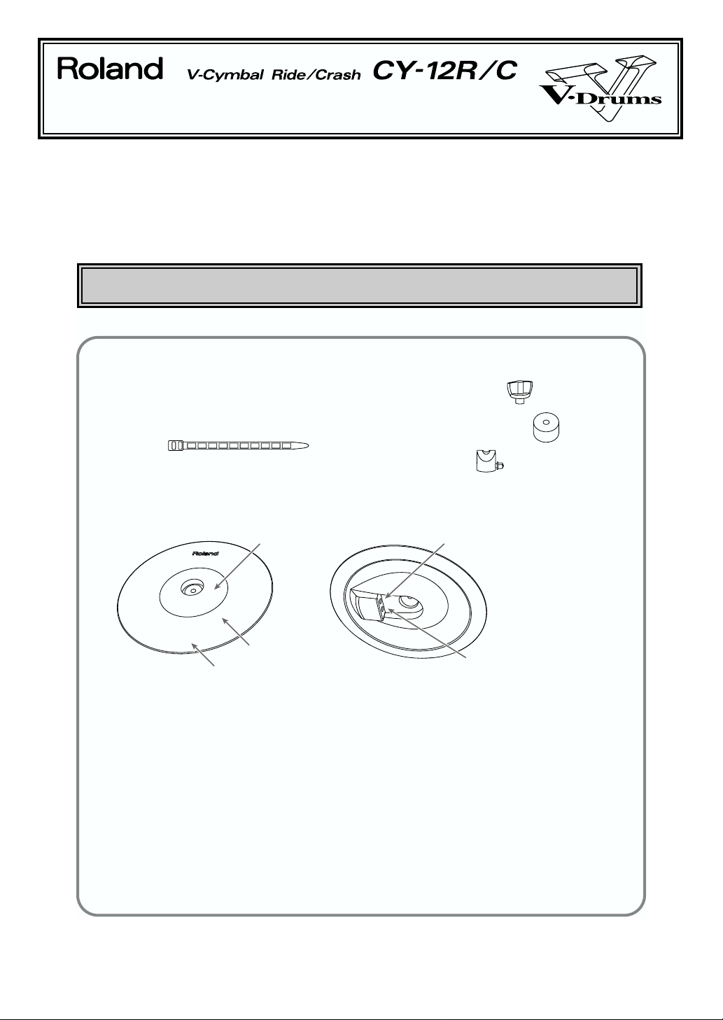
パッケージに入っているもの
□ CY-12R/C(Vシンバル)本体
□ 接続ケーブル
□ ケーブル・タイ
■ 取扱説明書(本書)
□ 保証書
□ ウイング・ナット
□ フェルト・ワッシャー
□ まわりどめ
各部の名称
ベル
ボウ
エッジ
BOW/EDGEアウトプット・ジャック
BOW/BELLアウトプット・ジャック
主な特長
• アコースティック・シンバルと同じような打感触
シンバルの形状だけでなく、スティックの跳ね返りやたたいた時の揺れまで考慮し設計されています。
ライド・シンバル、クラッシュ・シンバル、スプラッシュ・シンバルとして使用できます。
• 静かな打撃音
• ボウとエッジ、またはボウとベルのたたき分けやチョーク奏法が可能
ライド・シンバルとして使用するときはベル・ショット(P.6)、クラッシュ・シンバルとして使用するときは
エッジ・ショット(P.6)が可能です。
また、エッジ部を手でつかむことにより鳴っている音を止めるチョーク奏法ができます(P.7)。
• ローランドのすべてのドラム音源に対応(P.2)
• 3ウェイ・トリガーや打点位置検出が可能(TD-10+TDW-1Vシンバル対応バージョン使用時)(P.6)
©
2001 ローランド株式会社 本書の一部、もしくは全部を無断で複写・転載することを禁じます。
02892234 ’01-10-B3-11N
Page 2
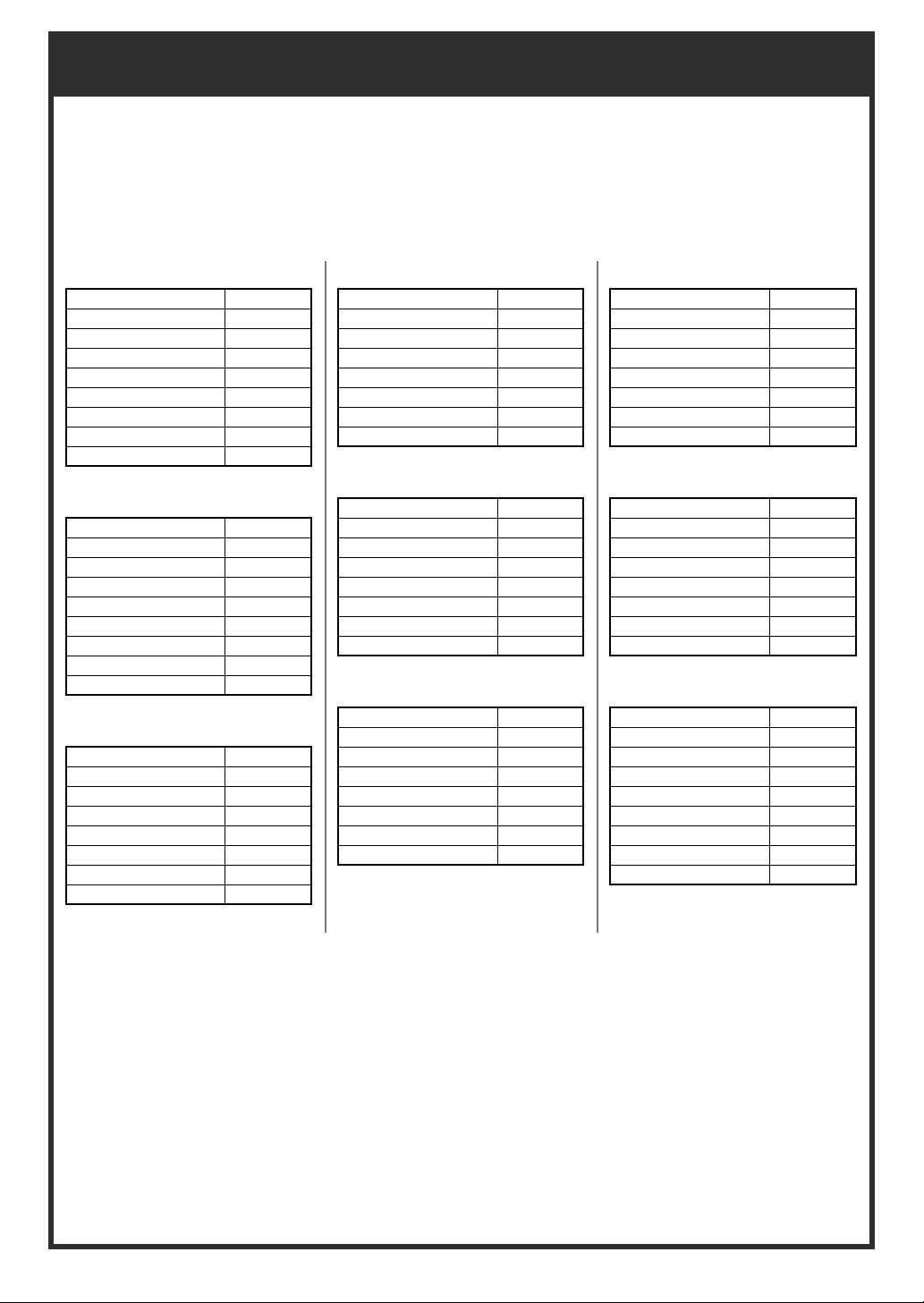
ドラム音源の推奨設定
CY-12R/C を各音源でご使用になるときのトリガー・パラメーターの推奨設定値です。
•
CY-12R/C はボウ・ショット、エッジ・ショット、ベル・ショット、チョーク奏法が可能です(P.6)。
ベル・ショットが鳴りにくいときは、「Scan Time」を調整してください。
•
パッドの取り付けかたやセッティングする位置などにより、さらにトリガー・パラメーターの調整が必要
•
な場合があります。
TD-10(
TDW-1 V-Cymbal Contro
Trigger Type RdA
Sensitivity 8
Threshold 4
Curve Linear
Scan Time (*1) 1.0
Retrigger Cancel (*1) 10
Mask Time (*1) 8
XtalkCancel (*1) 50
Mount Type (*1) CymMount
TD-10(TDW-1)
Trigger Type P7B
Sensitivity 8
Threshold 4
Curve Linear
Scan Time (*1) 1.8
Retrigger Cancel (*1) 5
Mask Time (*1) 8
XtalkCancel (*1) 40
Mount Type (*1) CymMount
TD-10(Non expanded)
Trigger Type Pd7
Sensitivity 5
Threshold 3
Curve Linear
Scan Time (*1) 1.5
Retrigger Cancel (*1) 5
Mask Time (*1) 8
XtalkCancel (*1) 40
TD-8
l)
TRIGGER TYPE CY1/PD7
SENSITIVITY (*1) 10
THRESHOLD (*1) 4
CURVE (*1) LINEAR
SCAN TIME (*1) 2.5
RETRIG CANCEL(*1) 8
MASK TIME (*1) 8
XTALK CANCEL (*1) 50
(*2)
TD-6
TrigType CY Type
Sensitivity (*1) 10
Threshold (*1) 4
TrigCurve (*1) LINEAR
Xtalk Cancel (*1) 50
Scan Time (*1) 2.5ms
Retrig Cancel (*1) 8
Mask Time (*1) 8ms
TD-7 (*3、*4)
Cross Talk Group 1
Velocity Curve Norm3
Choke Off
Max Dyna 5
MIn Dyna 1
Min Velo 1
Mask Time 0
Threshold 1
TD-5
TRIGGER TYPE P1
SENSITIVITY 8
THRESHOLD 2
CURVE Lnr
SCAN TIME 2.5
RETRIGGER CANCEL 3
MASK TIME 8
CROSSTALK CANCEL 50
SPD-20
Trig Sens 10
Trig Threshold 0
Trig Type Pd7
Trig Curve 0
Scan Time 2.5
Retrig Cancel 3
Mask Time 8
Crosstalk Cancel 30
HPD-15 (*4)
Input Mode HD/RM
Trig Type PD-9
Trig Sens 10
Curve Linear
Threshold 2
Scan Time 1ms
Retrig Cancel 2
Mask Time 4ms
X-Talk Rate 40%
*1: これらのトリガー・パラメーターは、トリガー・タイプを設定した後に設定する必要があります。
TD-8 バージョン・アップのお知らせ
*2:
2001 年 10 月より、トリガー・タイプに「CY1」を選べるようになりました。トリガー・タイプを「CY1」にする
と、その他のトリガー・パラメーターが自動的に推奨値に設定されるため、簡単に CY-12R/C 用の設定をすることが
できます。
それ以前の TD-8 をお使いの場合は、トリガー・タイプを「PD7」に設定してください。その後、その他のトリガー・
パラメーターを上記の推奨値に変更することで、同じように使用することができます。
TD-8 のバージョン・アップの方法は、最終ページの「TD-8 のバージョン・アップについて」をご覧ください。
*3: TD-7のトリガー・パラメーターは、ヘッド側とリム側を個別に設定することができます。ヘッド側とリム側を同じ設
定にしてください。また、TD-7 のトリガー・パラメーターはパッチごとに設定する必要があります。
*4: TD-7、HPD-15は、CY-12R/C のベル・ショット、エッジ・ショットには対応していますが、チョーク奏法には対応
していません。
2
Page 3
安全上のご注意
3
安全上のご注意
火災・感電・傷害を防止するには
注意の意味について警告と
取扱いを誤った場合に、使用者が
警告
注意
死亡または重傷を負う可能性が想
定される内容を表わしています。
取扱いを誤った場合に、使用者が
傷害を負う危険が想定される場合
および物的損害のみの発生が想定
される内容を表わしています。
※物的損害とは、家屋・家財およ
び家畜・ペットにかかわる拡大
損害を表わしています。
以下の指示を必ず守ってください
警告 警告
001
● この機器を使用する前に、以下の指示と取
扱説明書をよく読んでください。
....................................................................................................
002a
● この機器を分解したり、改造したりしない
でください。
....................................................................................................
003
● 修理/部品の交換などで、取扱説明書に書
かれていないことは、絶対にしないでくだ
さい。必ずお買い上げ店またはローランド・
サービスに相談してください。
....................................................................................................
004
● 次のような場所での使用や保存はしないで
ください。
○ 温度が極端に高い場所(直射日光の当
たる場所、暖房機器の近く、発熱する
機器の上など)
○ 水気の近く(風呂場、洗面台、濡れた
床など)や湿度の高い場所
○ 雨に濡れる場所
○ ホコリの多い場所
○ 振動の多い場所
....................................................................................................
005
● この機器の設置には、ローランドが推奨す
るスタンド(MDS シリーズ)、シンバル・
マウント(MDY シリーズ)を使用してく
ださい(P.5)。
....................................................................................................
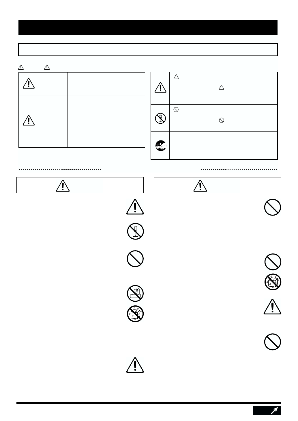
図記号の例
は、注意(危険、警告を含む)を表わしていま
す。
具体的な注意内容は、 の中に描かれています。
左図の場合は、「一般的な注意、警告、危険」を
表わしています。
は、禁止(してはいけないこと)を表わしてい
ます。
具体的な禁止内容は、 の中に描かれています。
左図の場合は、「分解禁止」を表わしています。
●は、強制(必ずすること)を表わしています。
具体的な強制内容は、●の中に描かれています。
左図の場合は、「電源プラグをコンセントから抜
くこと」を表わしています。
006
● この機器の設置にスタンド(MDS シリー
ズ)を使用する場合、ぐらついた所や傾い
た所にスタンド(MDS シリーズ)を設置
しないでください。安定した水平な所に設
置してください。機器を単独で設置する場
合も、同様に安定した水平な所に設置して
ください。
.....................................................................................................
011
● この機器に、異物(燃えやすいもの、硬貨、
針金など)や液体(水、ジュースなど)を
絶対に入れないでください。
.....................................................................................................
013
● お子様のいるご家庭で使用する場合、お子
様の取り扱いやいたずらに注意してくださ
い。必ず大人のかたが、監視/指導してあ
げてください。
.....................................................................................................
014
● この機器を落とさないでください。
.....................................................................................................
次へ
Page 4
注意 注意
104
● 接続したコードやケーブル類は、繁雑にな
らないように配慮してください。特に、コー
ドやケーブル類は、お子様の手が届かない
ように配慮してください。
....................................................................................................
106
● この機器の上に乗ったり、機器の上に重い
ものを置かないでください。
....................................................................................................
使用上のご注意
291a
3 〜 4 ページに記載されている「安全上のご注意」以外に、次のことに注意してください。
118
● ウィング・ナット、ワッシャー類、まわり
止めのボルトなどを外した場合は、小さな
お子様が誤って飲み込んだりすることのな
いようお子様の手の届かないところへ保管
してください。
.....................................................................................................
設置について
354b
● 直射日光の当たる場所や、発熱する機器の近く、閉
め切った車内などに放置しないでください。また、至
近距離から照らす照明器具(ピアノ・ライトなど)や
強力なスポット・ライトで長時間同じ位置を照射し
ないでください。変形、変色することがあります。
355
● 故障の原因になりますので、雨や水に濡れる場所で
使用しないでください。
356
● 本機の上にゴム製品やビニール製品などを長時間放
置しないでください。変形、変色することがありま
す。
357
● 本機の上に水の入った容器(花びんなど)、殺虫剤、
香水、アルコール類、マニキュア、スプレー缶など
を置かないでください。また、表面に付着した液体
は、すみやかに乾いた柔らかい布で拭き取ってくだ
さい。
お手入れについて
401a
● 通常のお手入れは、柔らかい布で乾拭きするか、堅
く絞った布で汚れを拭き取ってください。汚れが激
しいときは、中性洗剤を含んだ布で汚れを拭き取っ
てから、柔らかい布で乾拭きしてください。
402
● 変色や変形の原因となるベンジン、シンナーおよび
アルコール類は、使用しないでください。
修理について
451a
● お客様がこの機器を分解、改造された場合、以後の
性能について保証できなくなります。また、修理を
お断りする場合もあります。
453
● 当社では、この製品の補修用性能部品(製品の機能
を維持するために必要な部品)を、製造打切後 6 年
間保有しています。この部品保有期間を修理可能の
期間とさせていただきます。なお、保有期間が経過
した後も、故障箇所によっては修理可能の場合があ
りますので、お買い上げ店、または最寄りのローラ
ンド・サービスにご相談ください。
その他の注意について
553
● 故障の原因になりますので、入出力端子などに過度
の力を加えないでください。
556
● ケーブルの抜き差しは、ショートや断線を防ぐため、
プラグを持ってください。
558d
● 本機は、演奏時の打撃音を小さくする設計になって
いますが、床や壁を通じての振動は意外によく伝わ
りますので、特に夜間やヘッドホン使用時の演奏は、
隣近所に迷惑がかからないように注意しましょう。
559a
● 輸送や引っ越しをするときは、この機器が入ってい
たダンボール箱と緩衝材、または同等品で梱包して
ください。
562
●
接続には、付属のケーブルまたは当社ケーブル(PCS
シリーズなど)をご使用ください。他社製の接続ケー
ブルをご使用になる場合は、次の点にご注意ください。
○ 接続ケーブルには抵抗が入ったものがあります。
本機との接続には、抵抗入りのケーブルを使用し
ないでください。音が極端に小さくなったり、全
く聞こえなくなる場合があります。ケーブルの仕
様につきましては、ケーブルのメーカーにお問い
合わせください。
4
Page 5
スタンドに取り付ける
CY-12R/C を、別売のシンバル・マウント(MDY シリーズ)
やドラム・スタンド(MDS シリーズ)のシンバル・マウント
に取り付けます。
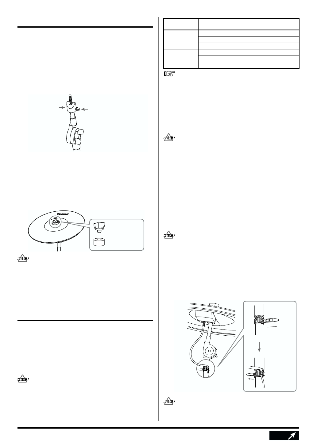
1.
市販のチューニング・キーでまわり止めのボルト
を締めます。
まわり止めは CY-12R/C の回転を防ぎ、ケーブルが引っ
張られたり、スタンドにからまったりしないようにする
ためのものです。
fig.01.j
まわり止め
(向きに注意)
2.
図の向きに合わせて、CY-12R/C を取り付けます。
ボルトがアウトプット・ジャックの反対側にくるように
してください。
3.
ウィング・ナットを適度な揺れが得られるように
締めます。
CY-12R/C に付属のフェルト・ワッシャーとウィング・
ナットをお使いください。
fig.02.j
市販のチューニング・キーで
締めつける
ウイング・ナット
アウトプット・
ジャック
BOW/BELL ボウ・ショット(P.6) ヘッド側
BOW/EDGE ボウ・ショット(P.6) ヘッド側
TD-10+TDW-1 V シンバル対応バージョンをお使いの場合
は、BOW/BELL アウトプットと BOW/EDGE アウトプット
を同時に使用することができます(3 ウェイ・トリガー)。詳
しくは「TD-10+TDW-1 V シンバル対応バージョンをお使い
の方へ」(P.6)をご覧ください。
対応している奏法 鳴らす音色
ベル・ショット(P.6) リム側
チョーク奏法(P.7) −
エッジ・ショット(P.6) リム側
チョーク奏法(P.7) −
接続のしかた
他の機器と接続するときは、誤動作やスピーカーなどの破損
を防ぐため、必ずすべての機器の音量を絞った状態で電源を
切ってください。
1.
CY-12R/C のアウトプット・ジャック(どちらかひ
とつ、TD-10+TDW-1 V シンバル対応バージョン
の場合を除く)と、ドラム音源のトリガー・イン
プット・ジャックを、付属のケーブルで接続しま
す。
付属のケーブルは、L字型になっているプラグを CY12R/Cに接続してください。CY-12R/C に無理な力が
かかるのを防ぐことができます。
フェルト・
ワッシャー
ウイング・ナットの締め付けがゆるいと、2 度鳴りする
•
ことがあります。
•
シンバル・マウント(MDY シリーズなど)に付属のワッ
シャーとフェルトは使用しません。
ドラム音源(TD-6、TD-8、 TD-10 など)に接続する
アウトプット・ジャックについて
CY-12R/C には、BOW/BELL と BOW/EDGE の 2 つのアウ
トプット・ジャックがあります。
ボウとベルを鳴らしたいときは BOW/BELL アウトプット・
ジャックを、ボウとエッジを鳴らしたいときは BOW/EDGE
アウトプット・ジャックをお使いください。
BOW/BELL または BOW/EDGE のどちらか 1 つのアウト
プット・ジャックのみを使用してください(TD-10+TDW-1
V シンバル対応バージョンを除く)。両方接続すると、2 つの
トリガー・インプットの音が同時に鳴ってしまいます。
エッジ・ショット、チョーク奏法をするときは、ドラム
音源のリム・ショットが可能なトリガー・インプット・
ジャックに接続してください。
TD-8のトリガー・インプット「1/2(KICK1/2)」、「11/
12(AUX1/2)」はリム・ショットに対応していません。
ケーブルを、ケーブル・タイで固定します。
2.
たたいたときのシンバル本体の揺れでケーブルが引っ張
られないように、ゆとりをもたせた状態にします。
fig.03.j
2回巻く
ゆとりを
もたせる
ケーブル・タイで
ケーブルを固定する
ケーブルがシンバル本体やスタンドに触れないように注
意してください。ケーブルが触れると 2 度鳴りするなど
滑り落ちないよう
に締めつける
折り返して
ケーブルを
固定する
5
次へ
Page 6

誤動作の原因となります。
ドラム音源のパラメーターを設定します。
3.
各音源のパラメーターの推奨値は、P.2 をご覧く
ださい。
TDW-1(Vシンバル対応バージョン)の取扱説明書では、3
ウェイ・トリガーについて CY-15R を使用して説明していま
す。CY-15Rを CY-12R/C に置き換えてお読みください。
ドラム音源の設定を行わずにご使用になると、次の症状
が出ます。
•
演奏時に音が出ないことがある(音量にムラがある)
•
音が小さい(感度が低い)
2 度鳴りする
•
ドラム音源のパラメーターの変更方法は、お使いの機器
の取扱説明書をご覧ください。
TD-10+TDW-1 V シンバル対応 バージョンをお使いの方へ
TD-10 + TDW-1 V シンバル対応バージョンをお使いの場合
は、3 ウェイ・トリガーの演奏が可能です。
※ TD-8 では、3 ウェイ・トリガーの演奏はできません。
3 ウェイ・トリガーについて
CY-12R/C と TD-10を 2 本のケーブルで接続することによ
り、ボウ/ベル/エッジの 3 つの音色をたたき分けて演奏す
ることができます。
TDW-1 の仕様により、3 ウェイ・トリガーとして使用できる
V シンバルは 1 つだけです。例えば、CY-15R を 3 ウェイ・
トリガーとして使用している場合に CY-12R/Cを追加して
も、3 ウェイ・トリガーとしては使用できません。
CY-12R/C の演奏方法
ボウ・ショット
シンバルの打面をたたく最も一般的な奏法です。接続したト
リガー・インプットのヘッド側の音色が鳴ります。
fig.04.j
ボウ
エッジ・ショット
エッジ(シンバルの端)をスティックのショルダー部でたた
く奏法です。接続したトリガー・インプットのリム側の音色
が鳴ります。
エッジ・ショットをするときは、ドラム音源のリム・ショットが
可能なトリガー・インプット・ジャックに接続してください。
fig.05.j
エッジ・センサー
接続/設定例
CY-12R/C
アウトプット
BOW/BELL 10/RIDE RdA
BOW/EDGE 11/AUX1 CTR
トリガー・タイプが「CTR」に設定されているトリガー・イ
ンプット(11/AUX 1)では、そのインプットだけにパッド
や V シンバルを接続しても音が鳴りません。
TD-10
トリガー・イン
プット
TD-10
トリガー・タイプ
奏法とトリガー・インプットの対応
奏法 TD-10トリガー・インプット
ボウ・ショット 10/RIDEヘッド
ベル・ショット 10/RIDEリム
エッジ・ショット 11/AUX 1 リム
※ この場合、11/AUX 1 ヘッドの音は鳴らせません。
3 ウェイ・トリガー用の設定について詳しくは、TDW-1 V シ
ンバル対応バージョンの取扱説明書をご覧ください。
ベル・ショット
ベルをたたく奏法です。接続したトリガー・インプットのリ
ム側の音色が鳴ります。
ベル・ショットをするときは、ドラム音源のリム・
•
ショットが可能なトリガー・インプット・ジャックに接
続してください。
ベル・ショットをするときはスティックのショルダー部
•
でたたいてください。
fig.05.j
ベル
6
次へ
Page 7

チョーク奏法
シンバルをたたいた後にエッジ付近を手でつかむと発音中の
音をミュートできます。
チョーク奏法をするときは、ドラム音源のリム・ショットが
可能なトリガー・インプット・ジャックに接続してください。
fig.07.jj
エッジ・センサー
に接続してご使用ください (P.5)。
2 度鳴りしてしまう
ケーブルが本体(V シンバル)に触れていませんか?
•
ケーブルが本体に触れないように、ケーブル・タイでケー
ブルを固定してください。またたたいた時の揺れで、ケー
ブルが引っ張られないように注意してください(P.5)。
•
まわり止め、フェルト・ワッシャー、ウイング・ナットを
正しく取り付けていますか?
まわり止めやウイング・ナットがぐらついていると 2 度鳴
りすることがあります。ドラム(チューニング)・キーで
しっかりと取り付けてください(P.5)。
※ 本体を正しく取り付けていても 2 度鳴りしてしまう場合
は、使用している音源(TD-6、TD-8、TD-10など)のリ
トリガー・キャンセルなどのトリガー・パラメーターを調
整してください。
故障かな?と思ったら
共通の内容
最初に確認してください
•
トリガー・タイプは正しく設定されていますか?
ご使用になる音源のトリガー・パラメーターの設定を行っ
てください(P.2)。
•
モノラル・ケーブルを使用していませんか?
モノラル・ケーブルを使用するとエッジ・ショット、ベ
ル・ショットをしても音色が変わりません。また、チョー
ク奏法もできません。
ステレオ・ケーブルをお使いください。
エッジ・ショットで音色が変わらない
•
BOW/EDGE アウトプットに接続していますか?
CY-12R/Cをエッジ・ショットに対応させるためには
BOW/EDGE アウトプットに接続してください(P.5)。
エッジ・センサーのあるエリアをたたいていますか?
•
CY-12R/Cは手前部分だけにエッジ・センサーが組み込
まれています(P.6)。
ベル・ショットで音色が変わらない
BOW/BELL アウトプットに接続していますか?
•
CY-12R/Cをベル・ショットに対応させるためには
BOW/BELL アウトプットに接続してください(P.5)。
ベル・ショットをするときは、スティックのショルダー部
•
でたたいてください(P.6)。
「Scan Time」を調整してください。
•
チョーク奏法ができない
エッジ・センサーのあるエリアをチョークしていますか?
•
CY-12R/Cは手前部分だけにエッジ・センサーが組み込
まれています(P.7)。
ライド・シンバルの音がおかしい
(他のシンバルの音が同時に聞こえる)
TDW-1 V シンバル対応バージョンを装着した TD-10 以外
•
の音源では、CY-12R/C の BOW/BELL アウトプットま
たは BOW/EDGE アウトプットのどちらか一方のみを音源
音が小さい
•
ドラム音源(TD-6、TD-8、TD-10など)の電源投入時に
パッドやシンバルをたたくと、弱くたたいたときの反応が
悪くなります。電源投入時にはパッドやシンバルをたたか
ないでください。
TD-10+TDW-1 V シンバル対応バー ジョンの場合
音が鳴らない
•
トリガー・タイプが「CTR」に設定されていませんか?
トリガー・タイプが「CTR」に設定されていると、そのイ
ンプットの音色は鳴りません(P.6)。
打点位置で音色が変化しない
•
CY-12R/C は、打点位置検出に対応したローランドの音源
の、指定された入力端子に接続した場合にのみ、打点位置
により音色が変化します。
•
打点位置により変化する音色については、ドラム音源
の取扱説明書の音色リストをご覧ください。
•
トリガー・タイプ「RdB」、「CrB」では打点位置を検
出しません。「RdA」、「CrA」をご使用ください。
主な仕様
CY-12R/C:V シンバル ライド/クラッシュ
パッド・サイズ:12 インチ
トリガー:3(ボウ/ベル/エッジ)
外形寸法:300(幅)× 300(奥行き)× 51(高さ)mm
質量:1.1kg
付属品: 取扱説明書、接続ケーブル、
ウィング・ナット、フェルト・ワッシャー、
まわり止め、ケーブル・タイ、保証書
別売品: シンバル・マウント(MDY-10U)、
スタンド(MDS-6、MDS-8、MDS-10)
※ 製品の仕様および外観は、改良のため予告なく変更するこ
とがあります。
7
Page 8

TD-8 のバージョン・アップについて
2001 年 10 月以前の TD-8をお使いの場合、TD-8をバージョン・アップすることで、より簡単に CY-12R/C の設定を
することができます。
TD-8 のバージョン確認方法
トリガー・タイプに「CY1」を選べますか?
•
「CY1」がある → バージョン・アップは必要ありません。
•
「CY1」がない → 以下の方法で TD-8 をバージョン・アップすることができます。
※ TD-8 のトリガー・タイプの設定方法については、「TD-8 取扱説明書」の P.128をご覧ください。
TD-8 の バージョン・アップ方法
※ バージョン・アップにより、本体に記憶されていたお客様のドラム・キットやパターン、ソングのデータや各種設定な
どが消失します。本体に重要なデータが入っている場合には、必ず他の MIDI 機器などにデータを保存してから(バル
ク・ダンプ:取扱説明書 P.149)バージョン・アップを行ってください。
本体メモリーの失われた記憶内容の修復に関しましては、補償を含めご容赦願います。
お使いの TD-8 をバージョン・アップするためには、次の 2 つの方法があります。
専用の SMF(スタンダード MIDI ファイル)を使って、システムをバージョン・アップします。
•
※ ダウンロードした SMF を再生するためには、MIDI シーケンサーや MIDI 対応コンピューターなどの MIDI 再生環境
が必要です。
SMFは、ローランドのホームページからダウンロードします。
ホームページ http://www.roland.co.jp/
※ ダウンロードした SMF の種類や再生順序など、詳しくはローランドのホームページ(http://www.roland.co.jp/)
をご覧ください。
•
お使いの TD-8 と、同梱の「バージョン・アップ申込書」を、ローランド・サービスにお持ちください。
システムのバージョン・アップを代行いたします。
詳しくは、保証書に同梱されている「サービスの窓口」に記載の営業所またはサービス・ステーションまでご相談く
ださい。
お問い合わせの窓口
商品のお取り扱いに関するお問い合わせは
ローランドお客様相談センター
受付時間:午前10時〜午後5時(土、日曜、祝日および弊社規定の休日を除く)
<電話番号>
・・・
■大阪 TEL(06)6345-9500 ■東京 TEL(03)3251-6150
<住所>
〒530-0004 大阪市北区堂島浜1-4-16 大和堂島ビル7F
修理に関するお問い合わせは
※上記窓口の名称、所在地、電話番号等は、予告なく変更することがありますのでご了承ください。
商品をお求めの販売店か保証書に同封されている「サービスの窓口」
・・・
に記載の営業所またはサービス・ステーションまでご相談ください。
ローランドお客様相談センターまでご相談
ください。尚、お問い合わせの際には取扱
説明書をご用意ください。
'01.5.1現在
Page 9

Owner's Manual
Thank you, and congratulations on your choice of the Roland CY-12R/C V-Cymbal.
Before using this unit, carefully read the sections entitled: “USING THE UNIT SAFELY” (p. 3–4) and
“IMPORTANT NOTES” (p. 4). These sections provide important information concerning the proper
operation of the unit. Additionally, in order to feel assured that you have gained a good grasp of every
feature provided by your new unit, Owner’s manual should be read in its entirety. The manual should be
saved and kept on hand as a convenient reference.
Before using the CY-12R/C, you need to make the settings for the percussion
sound module (p. 2).
Contents of the Package
❑ CY-12R/C (V-Cymbal unit)
❑ Connection Cable
❑ Cable Tie
■ Owner's Manual (this manual)
❑ Wing Nut
❑ Felt Washer
❑ Stopper
Names of the Components
Bell Portion
Bow Portion
Edge Portion
BOW/EDGE Output Jack
BOW/BELL Output Jack
Features
• Similar touch and feel as with acoustic cymbals
The superior design has taken into account not only the shape of the cymbal, but also the bounce of the stick, and
even the movement caused by playing. It can be used as a ride, crash, or splash cymbal.
• They're quiet!
• Separate tones in bow and edge, or bow and bell; choking possible
When the CY-12R/C is used as a ride cymbal, you can play bell shots (p. 6); edge shots (p. 6) can be played when using
it as a crash cymbal.
You can also use choking techniques, whereby you stop the sound by grasping the cymbal edge with your hand (p. 7).
• Compatible with all Roland percussion sound modules (p. 2)
• Three way triggering and positional sensing are possible
(When using the TD-10 + TDW-1 with V-Cymbal Control) (p. 6)
Copyright © 2001 ROLAND CORPORATION
All rights reserved. No part of this publication may be reproduced in any form without the
written permission of ROLAND CORPORATION.
02892234 ’01-10-B3-11N
Page 10

Recommended Settings for the Percussion Sound Module
8
4
10
8
4
Recommended settings for the trigger parameters when using the CY-12R/C with various percussion
sound modules.
• Bow shots, edge shots, bell shots and choking techniques are possible with the CY-12R/C (p. 6).
• If you find it difficult to get bell shots to sound, try adjusting the “Scan Time.”
• The trigger parameters should be adjusted as necessary to match the actual state of your configuration, and the
environment in which it is being used.
5
TDW-1 V-Cymbal Contro
TD-10 (
Trigger Type
Sensitivity
Threshold
Curve
Scan Time (*1) 1.0
Retrigger Cancel
Mask Time (*1) 8
Xtalk Cancel (*1) 50
Mount Type (*1) CymMount
RdA
Linear
(*1)
TD-10 (TDW-1)
Trigger Type
Sensitivity
Threshold
Curve
Scan Time (*1) 1.8
Retrigger Cancel
Mask Time (*1) 8
Xtalk Cancel (*1) 40
Mount Type (*1)
P7B
Linear
(*1)
CymMount
TD-10 (Non expanded)
Trigger Type
Sensitivity
Threshold
Curve
Scan Time (*1)
Retrigger Cancel
Mask Time (*1)
Xtalk Cancel (*1)
(*1)
Pd7
5
3
Linear
1.5
5
8
40
l)
TD-8
TRIGGER TYPE
SENSITIVITY
THRESHOLD
CURVE
SCAN TIME
RETRIG CANCEL
MASK TIME
XTALK CANCEL
(*2)
TD-6
TrigType
Sensitivity
Threshold
TrigCurve
Xtalk Cancel
Scan Time
Retrig Cancel
Mask Time
TD-7
Cross Talk Group
Velocity Curve Norm3
Choke Off
Max Dyna 5
MIn Dyna 1
Min Velo 1
Mask Time 0
Threshold 1
(*3, *4)
(*1)
(*1)
(*1)
(*1)
(*1)
(*1)
(*1)
(*1)
(*1)
(*1)
(*1)
(*1)
(*1)
(*1)
CY1/PD7
10
4
LINEAR
2.5
8
8
50
CY Type
10
4
LINEAR
50
2.5ms
8
8ms
1
TD-5
Trigger Type P1
Sensitivity 8
Threshold 2
Curve Lnr
Scan Time 2.5
Retrigger Cancel 3
Mask Time 8
Crosstalk Cancel 50
SPD-20
Trig Sens 10
Trig Threshold 0
Trig Type Pd7
Trig Curve 0
Scan Time 2.5
Retrig Cancel 3
Mask Time 8
Crosstalk Cancel 30
HPD-15
Input Mode HD/RM
Trig Type PD-9
Trig Sens 10
Curve Linear
Threshold 2
Scan Time 1ms
Retrig Cancel 2
Mask Time 4ms
X-Talk Rate 40%
(*4)
*1: You need to set each trigger parameter after setting the trigger type.
*2: Notice Regarding TD-8 Upgrade
As of October 2001, “CY1” has been added as a trigger type selection. Selecting “CY1” automatically sets the other trigger
parameters to the recommended values, allowing you to make the settings for the CY-12R/C simply and easily.
You can use the CY-12R/C even with previous TD-8 versions by selecting “PD7,” then manually setting the other trigger
parameters to the recommended values (as shown in the above list).
For more information about the TD-8 upgrade, consult with your retailer, the nearest Roland Service Center, or an
authorized Roland distributor, as listed on the “Information” page.
*3: Each trigger parameter can be set independently for the “head-side” and “rim-side.” Set to the same value for the head and
rim. Trigger parameters can be set individually for each patch.
*4: The TD-7 and the HPD-15 support the use of edge shots with the CY-12R/C, but they do not support choking techniques.
2
Page 11

USING THE UNIT SAFELY
Used for instructions intended to alert
the user to the risk of death or severe
injury should the unit be used
improperly.
Used for instructions intended to alert
the user to the risk of injury or material
damage should the unit be used
improperly.
* Material damage refers to damage or
other adverse effects caused with
respect to the home and all its
furnishings, as well to domestic
animals or pets.
001
• Before using this unit, make sure to read the
instructions below, and the Owner’s Manual.
................................................................................................
002a
• Do not open or perform any internal modifications on the unit.
................................................................................................
003
• Do not attempt to repair the unit, or replace
parts within it (except when this manual
provides specific instructions directing you
to do so). Refer all servicing to your retailer,
the nearest Roland Service Center, or an
authorized Roland distributor, as listed on the
“Information” page.
................................................................................................
004
• Never use or store the unit in places that are:
• Subject to temperature extremes (e.g.,
direct sunlight in an enclosed vehicle, near
a heating duct, on top of heat-generating
equipment); or are
• Damp (e.g., baths, washrooms, on wet
floors); or are
• Humid; or are
• Exposed to rain; or are
• Dusty; or are
• Subject to high levels of vibration.
................................................................................................
005
• This unit should be used only with a rack or
stand that is recommended by Roland.
................................................................................................
The symbol alerts the user to important instructions
or warnings.The specific meaning of the symbol is
determined by the design contained within the
triangle. In the case of the symbol at left, it is used for
general cautions, warnings, or alerts to danger.
The symbol alerts the user to items that must never
be carried out (are forbidden). The specific thing that
must not be done is indicated by the design contained
within the circle. In the case of the symbol at left, it
means that the unit must never be disassembled.
The ● symbol alerts the user to things that must be
carried out. The specific thing that must be done is
indicated by the design contained within the circle. In
the case of the symbol at left, it means that the powercord plug must be unplugged from the outlet.
006
• When using the unit with a rack or stand
recommended by Roland, the rack or stand
must be carefully placed so it is level and
sure to remain stable. If not using a rack or
stand, you still need to make sure that any
location you choose for placing the unit
provides a level surface that will properly
support the unit, and keep it from wobbling.
................................................................................................
011
• Do not allow any objects (e.g., flammable
material, coins, pins); or liquids of any kind
(water, soft drinks, etc.) to penetrate the unit.
................................................................................................
013
• In households with small children, an adult
should provide supervision until the child is
capable of following all the rules essential for
the safe operation of the unit.
................................................................................................
014
• Do not drop the unit!
................................................................................................
3
Next
Page 12

104
• Try to prevent cords and cables from
becoming entangled. Also, all cords and
cables should be placed so they are out of the
reach of children.
................................................................................................
106
118
• Should you remove wing nut, washers, or
stopper bolt, make sure to put them in a safe
place out of children's reach, so there is no
chance of them being swallowed accidentally.
................................................................................................
• Never climb on top of, nor place heavy
objects on the unit.
................................................................................................
IMPORTANT NOTES
291a
In addition to the items listed under “USING THE UNIT SAFELY” on page 3–4, please read and observe the
following:
Placement
354b
• Do not expose the unit to direct sunlight, place it
near devices that radiate heat, leave it inside an
enclosed vehicle, or otherwise subject it to temperature extremes. Also, do not allow lighting devices
that normally are used while their light source is
very close to the unit (such as a piano light), or
powerful spotlights to shine upon the same area of
the unit for extended periods of time. Excessive
heat can deform or discolor the unit.
355
• To avoid possible breakdown, do not use the unit in
a wet area, such as an area exposed to rain or other
moisture.
356
• Do not allow rubber, vinyl, or similar materials to
remain on the unit for long periods of time. Such
objects can discolor or otherwise harmfully affect
the finish.
357
• Do not put anything that contains water (e.g.,
flower vases) on the unit. Also, avoid the use of
insecticides, perfumes, alcohol, nail polish, spray
cans, etc., near the unit. Swiftly wipe away any
liquid that spills on the unit using a dry, soft cloth.
Maintenance
401a
• For everyday cleaning wipe the unit with a soft, dry
cloth or one that has been slightly dampened with
water. To remove stubborn dirt, use a cloth impregnated with a mild, non-abrasive detergent. Afterwards, be sure to wipe the unit thoroughly with a
soft, dry cloth.
402
• Never use benzine, thinners, alcohol or solvents of
any kind, to avoid the possibility of discoloration
and/or deformation.
Additional Precautions
553
• Use a reasonable amount of care when using its
jacks and connectors. Rough handling can lead to
malfunctions.
556
• When connecting / disconnecting all cables, grasp
the connector itself—never pull on the cable. This
way you will avoid causing shorts, or damage to
the cable’s internal elements.
558d
• This instrument is designed to minimize the extra-
neous sounds produced when it’s played. However,
since sound vibrations can be transmitted through
floors and walls to a greater degree than expected,
take care not to allow these sounds to become a
nuisance to neighbors, especially when performing
at night and when using headphones.
559a
• When you need to transport the unit, package it in
the box (including padding) that it came in, if
possible. Otherwise, you will need to use equivalent
packaging materials.
562
• Use a provided cable or a cable from Roland to make
the connection. If using some other make of
connection cable, please note the following precautions.
• Some connection cables contain resistors. Do not
use cables that incorporate resistors for
connecting to this unit. The use of such cables can
cause the sound level to be extremely low, or
impossible to hear. For information on cable
specifications, contact the manufacturer of the
cable.
4
Page 13

Attaching to a Stand
Attach the CY-12R/C with the optional cymbal mount (MDY
series), or drum stand cymbal mount (MDS series).
1. Use a commercially available drum key to
tighten the stopper bolt.
The stopper keeps the CY-12R/C from turning, and
prevents the cables from catching or getting tangled on the
stand.
fig.01.e
Stopper
(Be sure to
orient it correctly)
Tighten the bolt with
a commercially available
drum key
Output Jack Corresponding Play
Methods
BOW/BELL Bow Shot (p. 6) Head
Bell Shot (p. 6) Rim
Choke (p. 7) –
BOW/EDGE Bow Shot (p. 6) Head
Edge Shot (p. 6) Rim
Choke (p. 7) –
If you are using the TD-10 + TDW-1 with V-Cymbal Control,
you can use both the BOW/BELL and BOW/EGDE output
jacks at the same time (Three Way Triggering). For more
details, refer to “If Using TD-10 + TDW-1 with V-Cymbal
Control” (p. 6).
Tones
Sounded
Making the Connections
2. Attach the CY-12R/C so the unit is oriented as
shown in the diagram (bolt should be opposite
the output jacks).
3. Tighten the wing nut to obtain the desired
movement.
Use the included felt washer and the wing nut.
fig.02.e
Wing Nut
Felt Washer
• Double sounding may occur if the wing nut is loose.
• Do not use the washer or felt included with the cymbal
mount (MDY series).
Connecting to
a Percussion Sound Module
(TD-6, TD-8, TD-10, etc.)
About the Output Jacks
The CY-12R/C features two different output jacks, BOW/BELL
and BOW/EDGE.
Use the BOW/BELL output jack when you want to play the
bow and the bell sounds; use the BOW/EDGE output jack
when you want to play the bow and the edge sounds.
Use either the BOW/BELL or BOW/EGDE output jack, but
not both at the same time (except for the TD-10 + TDW-1 with
V-Cymbal Control).
Connecting both jacks results in two separate trigger inputs
playing simultaneously.
To prevent malfunction and/or damage to speakers or other
devices, always turn down the volume, and turn off the power
on all devices before making any connections.
1.
Use the included cable to connect one of the CY12R/C’s output jacks (either one, but not both,
EXCEPT when using with the TD-10 + TDW-1
with V-Cymbal Control installed) to the drum
sound module’s trigger input jack.
Connect the L-shaped plug of the included cable to the
CY-12R/C. This will prevent strain from being applied to
the CY-12R/C.
To make use of edge shot and choking play techniques,
you'll need to connect to a trigger input jack on the
percussion sound module that accommodates rim shots.
The TD-8's “1/2 (KICK 1/2)” and “11/12 (AUX 1/2)” do
not support rim shots.
2. Secure the cable with cable ties.
Leave enough slack so that the cable is not pulled by any
shaking or vibration of the cymbal when it is struck.
fig.CY03.e
Wind the cable
tie twice
Leave some
slack in
the cable
Secure the cable in place
with the cable tie
Take care to ensure that the cable does not come into
contact with the cymbal or stand. Contact between the
cable and the cymbal or stand can result in problems,
Tighten it
not to slip
Turn back
to fix the
cable
5
Next
Page 14

such as double sounding.
3. Make the trigger settings for the percussion
sound module. For the recommended values,
refer to p. 2.
The TDW-1 with V-Cymbal Control Owner's Manual contains
an explanation of how the CY-15R is used with Three Way
Triggering. Substitute “CY-12R/C” for “CY-15R” as you read
through the text.
Should you neglect to make the appropriate settings for the
percussion sound module.
• Sometimes it does not sound (uneven volume)
• The volume is too low (reduced sensitivity)
• Double sounding may occur
For information on how to change the parameters for a
percussion sound module, refer to its owner’s manual.
If Using TD-10 + TDW-1 with V-Cymbal Control
When you use the TD-10 + TDW-1 V-Cymbal Control, three
way triggering is possible.
* Three Way Triggering is not available with the TD-8.
About Three Way Triggering
By using two cables to connect the CY-12R/C and a TD-10, you
can then perform using three different tones: bow, bell, and edge.
TDW-1 specifications allow the Three Way Triggering
function to be used with only one V-Cymbal. For example, if
you use the Three Way Triggering function with one CY-15R,
you would not be able to use Three Way Triggering if you
added another CY-12R/C.
Playing Methods
Bow Shot
This is the most common playing method, playing the pad face
of the cymbal. It corresponds to the sound of the “head-side” of
the connected trigger input.
Bow
Edge Shot
This playing method involves striking the edge with the
shoulder of the stick. It corresponds to the sound of the “rimside” of the connected trigger input.
To make use of edge shot, you'll need to connect to a trigger
input jack on the percussion sound module that
accommodates rim shots.
Edge sensor
Connections/Examples of Settings
CY-12R/C
Output
BOW/BELL 10/RIDE RdA
BOW/EDGE 11/AUX1 CTR
If you connect a pad or a V-Cymbal ONLY to the trigger input
for which trigger type is set to the “CTR”(11/AUX 1), it will
not work.
TD-10 Trigger
Input
TD-10 Trigger
Type
Correspondences Between Playing Methods and Trigger Input
Playing Methods TD-10 Trigger Input
Bow Shot 10/RIDE Head
Bell Shot 10/RIDE Rim
Edge Shot 11/AUX 1 Rim
* Head-side tones for the trigger input 11/AUX 1 cannot be sounded.
For more details on the settings for Three Way Triggering,
refer to the TDW-1 with V-Cymbal Control Owner's Manual.
Bell Shot
This playing method involves striking the bell. It corresponds
to the sound of the “rim-side” of the connected trigger input.
• To make use of bell shot, you'll need to connect to a
trigger input jack on the percussion sound module that
accommodates rim shots.
• Use the shoulder of the stick when playing bell shots.
Bell
6
Next
Page 15

Choking
Choking (pinching) the cymbal’s edge with the hand
immediately after hitting the cymbal makes the sound stop.
To make use of choking play techniques, you’ll need to
connect to a trigger input jack on the percussion sound
module that accommodates rim shots.
fig.CY07.e
Edge sensor
Troubleshooting
Issues Affecting The Overall System
Check these first
• Is the trigger type set correctly?
Make the trigger parameter settings for your percussion
sound module (p. 2).
• Is a monaural cable being used?
When a monaural cable is used, the sound does not
change when an edge shot or a bell shot is made. Choke
play is not possible, either.
Use stereo cable.
The sound does not change when an edge
shot is made
• Is the cable connected to the BOW/EDGE output?
Make the connection to the BOW/EDGE output to enable
the CY-12R/C to support edge shots (p. 5).
• Are you striking the cymbal in the area with the edge
sensors?
Edge sensors are embedded only in the part of the CY12R/C directly in front (p. 6).
The sound does not change when a bell shot
is made
• Is the cable connected to the BOW/BELL output?
Make the connection to the BOW/BELL output to enable
the CY-12R/C to support bell shots (p. 5).
• Use the shoulder of the stick when playing bell shots
(p. 6).
• Adjust the “Scan Time.”
Choke play is not possible
• Are you choking the cymbal in the area with the edge
sensors?
Edge sensors are embedded only in the part of the CY12R/C directly in front (p. 7).
Ride cymbal sounds odd
(Other cymbal sound is heard simultaneously)
• If using a sound module other than the TD-10 furnished
with the TDW-1 with V-Cymbal Control, connect either
the CY-12R/C’s BOW/BELL output or the BOW/EDGE
output (p. 5).
Double sounding
• Are any cables touching the CY-12R/C?
Secure the cables in place with the cable ties so that they
do not touch the units. Also, be careful to make sure that
the cables are not pulled by the movement of a cymbal
when struck (p. 5).
• Are the stopper, felt washer, and wing nut attached
correctly?
Double triggering may occur if the stopper and/or wing
nut is loose. Use a tuning key (drum key) to tighten
properly.
* If double triggering still occurs, try adjusting trigger
parameters, such as Retrigger Cancel, on the sound module you
are using (TD-6, TD-8, TD-10, etc.)
The volume level is too low
• If the cymbal is struck while power to the drum module
(such as the TD-6, TD-8, or TD-10) is turned on, the
response to light hits will be poor. Do not strike pads or
cymbals while turning on the power.
When using the TD-10 + TDW-1 with VCymbal Control
No sound is heard
• Is the trigger type set to “CTR”?
Tones from inputs for which the trigger type is set to
“CTR” do not sound (p. 6).
The sound does not vary when the striking
position changes
• The CY-12R/C is capable of the positional detection
feature. Positional detection is possible when
plugged into the specified input on a Roland sound
module with this feature.
• For more on tones that can change according to the
part of the cymbal struck, refer to the tone list in the
Owner's Manual that came with your drum module.
• With trigger types “RdB” and “CrB,” positional
sensing is not possible. Use “RdA” or “CrA.”
Specifications
CY-12R/C: V-Cymbal Ride/Crash
Pad Size: 12 inches
Trigger: 3 (Bow/Bell/Edge)
Dimensions: 300 (W) x 300 (D) x 51 (H)
11-13/16 (W) x 11-13/16 (W) x 2-1/16 (H)
Weight: 1.1 kg
2 lbs 7 oz
Accessories: Owner’s Manual, Connection Cable,
Wing Nut, Felt Washer, Stopper, Cable Tie
Options: Cymbal Mount (MDY-10U)
Stand (MDS-6, MDS-8, MDS-10)
* In the interest of product improvement, the specifications and/or
appearance of this unit are subject to change without prior notice.
7
Page 16

Information
When you need repair service, call your nearest Roland Service Center or authorized Roland distributor in your country as
shown below.
AFRICA
AFRICA
EGYPT
Al Fanny Trading Office
P.O. Box 2904,
El Horrieh Heliopolos, Cairo,
EGYPT
TEL: (02) 4185531
REUNION
Maison FO - YAM Marcel
25 Rue Jules Hermann,
Chaudron - BP79 97 491
Ste Clotilde Cedex,
REUNION ISLAND
TEL: 28 29 16
SOUTH AFRICA
That Other Music Shop
(PTY) Ltd.
11 Melle St., Braamfontein,
Johannesbourg
Republic of SOUTH AFRICA
P.O.Box 32918, Braamfontein 2017
Republic of SOUTH AFRICA
TEL: (011) 403 4105
Paul Bothner (PTY) Ltd.
17 Werdmuller Centre Claremont
7700
Republic of SOUTH AFRICA
P.O. Box 23032
Claremont, Cape Town
SOUTH AFRICA, 7735
TEL: (021) 674 4030
ASIA
CHINA
Beijing Xinghai Musical
Instruments Co., Ltd.
6 Huangmuchang Chao Yang
District, Beijing, CHINA
TEL: (010) 6774 7491
Shanghai Xingtong Acoustics
Equipment CO.,Ltd.
Rm.1108, No.2240 Pudong South
Road Shanghai, CHINA
TEL: (021) 6873 4123
HONG KONG
Tom Lee Music Co., Ltd.
Service Division
22-32 Pun Shan Street, Tsuen
Wan, New Territories,
HONG KONG
TEL: 2415 0911
INDIA
Rivera Digitec (India) Pvt. Ltd.
409, Nirman Kendra Mahalaxmi
Flats Compound Off. Dr. Edwin
Moses Road, Mumbai-400011,
INDIA
TEL: (022) 498 3079
INDONESIA
PT Citra IntiRama
J1. Cideng Timur No. 15J-150
Jakarta Pusat
INDONESIA
TEL: (021) 6324170
KOREA
Cosmos Corporation
1461-9, Seocho-Dong,
Seocho Ku, Seoul, KOREA
TEL: (02) 3486-8855
MALAYSIA
BENTLEY MUSIC SDN BHD
140 & 142, Jalan Bukit Bintang
55100 Kuala Lumpur,MALAYSIA
TEL: (03) 2144-3333
PHILIPPINES
G.A. Yupangco & Co. Inc.
339 Gil J. Puyat Avenue
Makati, Metro Manila 1200,
PHILIPPINES
TEL: (02) 899 9801
SINGAPORE
Swee Lee Company
150 Sims Drive,
SINGAPORE 387381
TEL: 846-3676
CRISTOFORI MUSIC PTE
LTD
Blk 3014, Bedok Industrial Park E,
#02-2148, SINGAPORE 489980
TEL: 243 9555
TAIWAN
ROLAND TAIWAN
ENTERPRISE CO., LTD.
Room 5, 9fl. No. 112 Chung Shan
N.Road Sec.2, Taipei, TAIWAN,
R.O.C.
TEL: (02) 2561 3339
THAILAND
Theera Music Co. , Ltd.
330 Verng NakornKasem, Soi 2,
Bangkok 10100, THAILAND
TEL: (02) 2248821
VIETNAM
Saigon Music
138 Tran Quang Khai St.,
District 1
Ho Chi Minh City
VIETNAM
TEL: (08) 844-4068
AUSTRALIA/
NEW ZEALAND
AUSTRALIA
Roland Corporation
Australia Pty., Ltd.
38 Campbell Avenue
Dee Why West. NSW 2099
AUSTRALIA
TEL: (02) 9982 8266
NEW ZEALAND
Roland Corporation Ltd.
32 Shaddock Street, Mount Eden,
Auckland, NEW ZEALAND
TEL: (09) 3098 715
CENTRAL/LATIN
AMERICA
ARGENTINA
Instrumentos Musicales S.A.
Florida 656 2nd Floor
Office Number 206A
Buenos Aires
ARGENTINA, CP1005
TEL: (54-11) 4- 393-6057
BRAZIL
Roland Brasil Ltda
Rua San Jose, 780 Sala B
Parque Industrial San Jose
Cotia - Sao Paulo - SP, BRAZIL
TEL: (011) 4615 5666
COSTA RICA
JUAN Bansbach
Instrumentos Musicales
Ave.1. Calle 11, Apartado 10237,
San Jose, COSTA RICA
TEL: (506)258-0211
CHILE
Comercial Fancy ΙΙ S.A.
Avenida Rancagua #0330
Providencia Santiago, CHILE
TEL: 56-2-373-9100
EL SALVADOR
OMNI MUSIC
75 Avenida Notre YY Alameda,
Juan Pablo 2, No. 4010
San Salvador, EL SALVADOR
TEL: (503) 262-0788
MEXICO
Casa Veerkamp, s.a. de c.v.
Av. Toluca No. 323, Col. Olivar
de los Padres 01780 Mexico D.F.
MEXICO
TEL: (525) 668 04 80
PANAMA
SUPRO MUNDIAL, S.A.
Boulevard Andrews, Albrook,
Panama City,
REP. DE PANAMA
TEL: (507) 315-0101
PARAGUAY
Distribuidora De
Instrumentos Musicales
J.E. Olear y ESQ. Manduvira
Edeficio, El Dorado Planta Baja
Asuncion PARAGUAY
TEL: 595-21-492147
PERU
VIDEO Broadcast S.A.
Portinari 199 (ESQ. HALS),
San Borja, Lima 41,
REP. OF PERU
TEL: 51-14-758226
URUGUAY
Todo Musica S.A.
Cuareim 1844, Montevideo,
URUGUAY, CP11200
TEL: 5982-924-2335
VENEZUELA
Musicland Digital C.A.
Av. Francisco de Miranda,
Centro Parque de Cristal, Nivel
C2 Local 20 Caracas
VENEZUELA
TEL: (02) 285 9218
EUROPE
AUSTRIA
Roland Austria GES.M.B.H.
Siemensstrasse 4, P.O. Box 74,
A-6063 RUM, AUSTRIA
TEL: (0512) 26 44 260
BELGIUM/HOLLAND/
LUXEMBOURG
Roland Benelux N. V.
Houtstraat 3, B-2260, Oevel
(Westerlo) BELGIUM
TEL: (014) 575811
DENMARK
Roland Scandinavia A/S
Nordhavnsvej 7, Postbox 880,
DK-2100 Copenhagen
DENMARK
TEL: (039)16 6200
FRANCE
Roland France SA
4, Rue Paul Henri SPAAK,
Parc de l'Esplanade, F 77 462 St.
Thibault, Lagny Cedex FRANCE
TEL: 01 600 73 500
FINLAND
Roland Scandinavia As,
Filial Finland
Lauttasaarentie 54 B
Fin-00201 Helsinki, FINLAND
TEL: (9) 682 4020
GERMANY
Roland Elektronische
Musikinstrumente HmbH.
Oststrasse 96, 22844 Norderstedt,
GERMANY
TEL: (040) 52 60090
GREECE
STOLLAS S.A.
Music Sound Light
155, New National Road
26422 Patras, GREECE
TEL: 061-435400
HUNGARY
Intermusica Ltd.
Warehouse Area ‘DEPO’ Pf.83
H-2046 Torokbalint, HUNGARY
TEL: (23) 511011
IRELAND
Roland Ireland
Audio House, Belmont Court,
Donnybrook, Dublin 4.
Republic of IRELAND
TEL: (01) 2603501
ITALY
Roland Italy S. p. A.
Viale delle Industrie 8,
20020 Arese, Milano, ITALY
TEL: (02) 937-78300
NORWAY
Roland Scandinavia Avd.
Kontor Norge
Lilleakerveien 2 Postboks 95
Lilleaker N-0216 Oslo
NORWAY
TEL: 273 0074
POLAND
P. P. H. Brzostowicz
UL. Gibraltarska 4.
PL-03664 Warszawa POLAND
TEL: (022) 679 44 19
PORTUGAL
Tecnologias Musica e Audio,
Roland Portugal, S.A.
Cais Das Pedras, 8/9-1 Dto
4050-465 PORTO
PORTUGAL
TEL: (022) 608 00 60
ROMANIA
FBS LINES
Piata Libertatii 1,
RO-4200 Gheorghehi
TEL: (066) 164-609
RUSSIA
MuTek
3-Bogatyrskaya Str. 1.k.l
107 564 Moscow, RUSSIA
TEL: 095 169 5043
SPAIN
Roland Electronics
de España, S. A.
Calle Bolivia 239, 08020
Barcelona, SPAIN
TEL: (93) 308 1000
SWEDEN
Roland Scandinavia A/S
SWEDISH SALES OFFICE
Danvik Center 28, 2 tr.
S-131 30 Nacka SWEDEN
TEL: (08) 702 0020
SWITZERLAND
Roland (Switzerland) AG
Musitronic AG
Gerberstrasse 5, Postfach,
CH-4410 Liestal, SWITZERLAND
TEL: (061) 921 1615
UKRAINE
TIC-TAC
Mira Str. 19/108
P.O. Box 180
295400 Munkachevo, UKRAINE
TEL: (03131) 414-40
UNITED KINGDOM
Roland (U.K.) Ltd.
Atlantic Close, Swansea
Enterprise Park, SWANSEA
SA7 9FJ,
UNITED KINGDOM
TEL: (01792) 700139
MIDDLE EAST
BAHRAIN
Moon Stores
Bab Al Bahrain Road,
P.O. Box 20077
State of BAHRAIN
TEL: 211 005
CYPRUS
Radex Sound Equipment Ltd.
17 Diagorou St., P.O. Box 2046,
Nicosia CYPRUS
TEL: (02) 453 426
IRAN
MOCO, INC.
No.41 Nike St.Dr.Shariyati Ave.
Roberoye Cerahe Mirdamad
Tehran, IRAN
TEL: 285 4169
ISRAEL
Halilit P. Greenspoon &
Sons Ltd.
8 Retzif Ha'aliya Hashnya St.
Tel-Aviv-Yafo ISRAEL
TEL: (03) 6823666
JORDAN
AMMAN Trading Agency
Prince Mohammed St. P.O. Box
825 Amman 11118 JORDAN
TEL: (06) 4641200
KUWAIT
Easa Husain Al-Yousifi
Abdullah Salem Street,
Safat KUWAIT
TEL: 5719499
LEBANON
A. Chahine & Fils
P.O. Box 16-5857 Gergi Zeidan St.
Chahine Building, Achrafieh
Beirut, LEBANON
TEL: (01) 335799
QATAR
Al Emadi Co. (Badie Studio
& Stores)
P.O. Box 62,
DOHA QATAR
TEL: 4423-554
SAUDI ARABIA
aDawliah Universal
Electronics APL
Corniche Road, Aldossary Bldg.,
1st Floor
SAUDI ARABIA
P.O.Box 2154, Alkhobar 31952
SAUDI ARABIA
TEL: (03) 898 2081
SYRIA
Technical Light & Sound
Center
Khaled Ibn Al Walid St.
P.O. Box 13520
Damascus - SYRIA
TEL: (011) 2235 384
TURKEY
Barkat muzik aletleri ithalat
ve ihracat Ltd Sti
Siraselviler cad.Guney is hani 8486/6, Taksim. Istanbul. TURKEY
TEL: (0212) 2499324
U.A.E.
Zak Electronics & Musical
Instruments Co. L.L.C.
Zabeel Road, Al Sherooq Bldg.,
No. 14, Grand Floor DUBAI
U.A.E.
TEL: (04) 3360715
NORTH AMERICA
CANADA
Roland Canada Music Ltd.
(Head Office)
5480 Parkwood Way Richmond
B. C., V6V 2M4 CANADA
TEL: (0604) 270 6626
Roland Canada Music Ltd.
(Toronto Office)
Unit 2, 109 Woodbine Downs
Blvd, Etobicoke, ON
M9W 6Y1 CANADA
TEL: (0416) 213 9707
U. S. A.
Roland Corporation U.S.
5100 S. Eastern Avenue
Los Angeles, CA 90040-2938,
U. S. A.
TEL: (323) 890 3700
As of May 15, 2001 (Roland)
 Loading...