

Page 1
CX-24/12
USER’S MANUAL
Thank you very much for purchasing the CX-24/12.
• To ensure correct and safe usage with a full understanding of this product's performance, please be sure
to read through this manual completely and store it in
a safe location.
• Unauthorized copying or transferral, in whole or in
part, of this manual is prohibited.
• The contents of this operation manual and the
specifications of this product are subject to change
without notice.
• The operation manual and the product have been
prepared and tested as much as possible. If you find
any misprint or error, please inform us.
• Roland DG Corp. assumes no responsibility for any
direct or indirect loss or damage which may occur
through use of this product, regardless of any failure
to perform on the part of this product.
• Roland DG Corp. assumes no responsibility for any
direct or indirect loss or damage which may occur
with respect to any article made using this product.
Page 2

Contents
Contents
To Ensure Safe Use .................................. 3
About the Labels Affixed to the Unit .............................. 5
Pour utiliser en toute sécurité.................... 6
À propos des étiquettes collées sur l'appareil .................. 8
1 Checking Supplied Items .................... 9
2 Part Names and Functions................ 10
2-1 Front View ........................................................... 10
2-2 Rear View ............................................................ 10
2-3 Operation Panel ................................................... 11
3 Preparing the CX-24/12 .................... 12
3-1 Setting.................................................................. 12
3-2 Connection........................................................... 13
3-3 Installing the Driver............................................. 14
3-4 Port Setting .......................................................... 15
7 Repeating the Same Cutting ............. 39
8 Cutting Printed Material..................... 41
8-1 Using Crop Marks ............................................... 41
8-2 Shape and Layout of Crop Marks........................ 41
8-3 Loading the Material ........................................... 42
8-4 Performing Operations Using Crop Marks.......... 43
8-5 When Crop Marks Cannot Be Read .................... 49
8-6 When the Printing and Cutting Locations Are
Misaligned ........................................................... 50
9 About the Blades and Materials ........ 51
9-1 Blade and Material Combinations ....................... 51
9-2 About the Materials ............................................. 52
10 Display Menu Descriptions................ 55
10-1 How to Read This Chapter .................................. 55
10-2 Display Menu Descriptions ................................. 55
11 Display Menu Flowchart.................... 63
4 Basic Operation................................. 18
4-1 Installing a Blade ................................................. 18
4-2 Loading the Material ........................................... 19
4-3 Turning on the Power .......................................... 22
4-4 Checking Material Feed....................................... 24
4-5 When Performing Long Cutting .......................... 25
4-6 Setting the Origin Point ....................................... 26
4-7 Performing a Cutting Test (How to Adjust Blade
Force/Adjusting the Cutter Blade)....................... 27
4-8 Downloading Cutting Data.................................. 29
4-9 Applying the Completed Cutout.......................... 34
4-10 When Cutting Is Completed ................................ 36
12 What to Do If... .................................. 65
12-1 If the CX-24/12 Doesn't Run... ............................ 65
12-2 The Material Slips Away from the Pinch Rollers
During the Cutting Process.................................. 66
12-3 Uncut Areas Remain, or Areas Are Not
Cleanly Cut .......................................................... 67
12-4 The Results of Cutting Are Displaced, and Uncut
Portions Remain .................................................. 67
12-5 Error Messages .................................................... 68
13 Instruction Support Chart .................. 70
5 Performing a Self-Test....................... 37
14 Specifications .................................... 71
6 Plotting on Paper Media.................... 38
Index ....................................................... 73
Windows®, Windows NT® and MS-DOS are registered trademarks or trademarks of Microsoft® Corporation in the United States and/or other
countries.
Macintosh is a registered trademark or trademark of Apple Computer, Inc. in the USA and other countries.
IBM is a registered trademark of International Business Machines Corporation.
Adobe Illustrator is a registered trademark or trademark of Adobe Systems Incorporated in the U.S.A. and other countries.
Adobe and Acrobat are trademarks of Adobe Systems Incorporated.
Copyright © 2000 Roland DG Corporation
http://www.rolanddg.com/
2
Page 3
To Ensure Safe Use
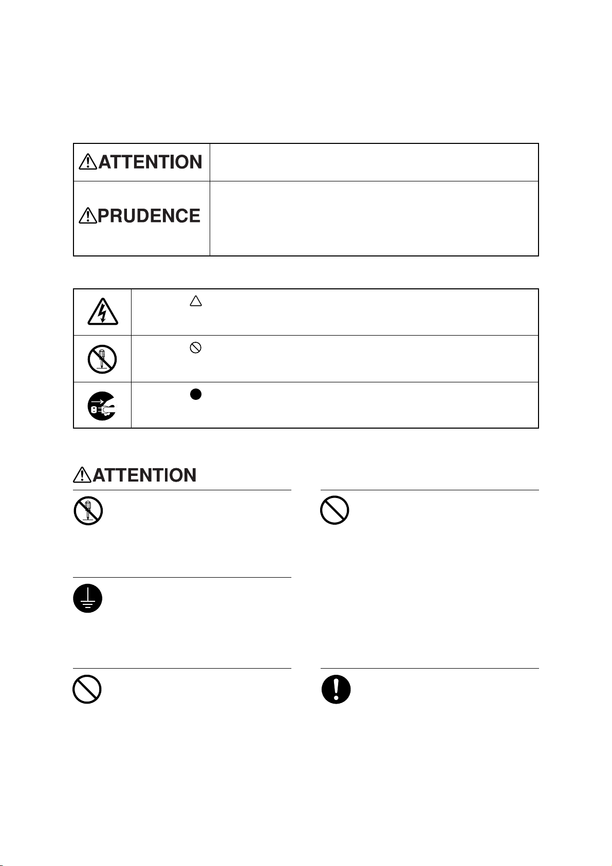
About and Notices
Used for instructions intended to alert the user to the risk of death or severe
injury should the unit be used improperly.
Used for instructions intended to alert the user to the risk of injury or material
damage should the unit be used improperly.
* Material damage refers to damage or other adverse effects caused with
respect to the home and all its furnishings, as well to domestic animals or
pets.
About the Symbols
The symbol alerts the user to important instructions or warnings. The specific meaning of
the symbol is determined by the design contained within the triangle. The symbol at left means
"danger of electrocution."
The symbol alerts the user to items that must never be carried out (are forbidden). The
specific thing that must not be done is indicated by the design contained within the circle. The
symbol at left means the unit must never be disassembled.
The symbol alerts the user to things that must be carried out. The specific thing that must
be done is indicated by the design contained within the circle. The symbol at left means the
power-cord plug must be unplugged from the outlet.
Do not disassemble, repair, or
modify.
Doing so may lead to fire or abnormal
operation resulting in injury.
Ground the unit with the ground
wire.
Failure to do so may result in risk of
electrical shock in the even of a mechanical
problem
Do not use with any electrical power
supply that does not meet the
ratings displayed on the unit.
Use with any other power supply may lead
to fire or electrocution.
Do not use while in an abnormal
state (i.e., emitting smoke, burning
odor, unusual noise, or the like).
Doing so may result in fire or electrical
shock.
Immediately switch off the power, unplug
the power cord from the electrical outlet,
and contact your authorized Roland dealer
or service center.
Use only with the power cord
included with this product
Use with other than the included power cord
may lead to fire or electrocution.
3
Page 4
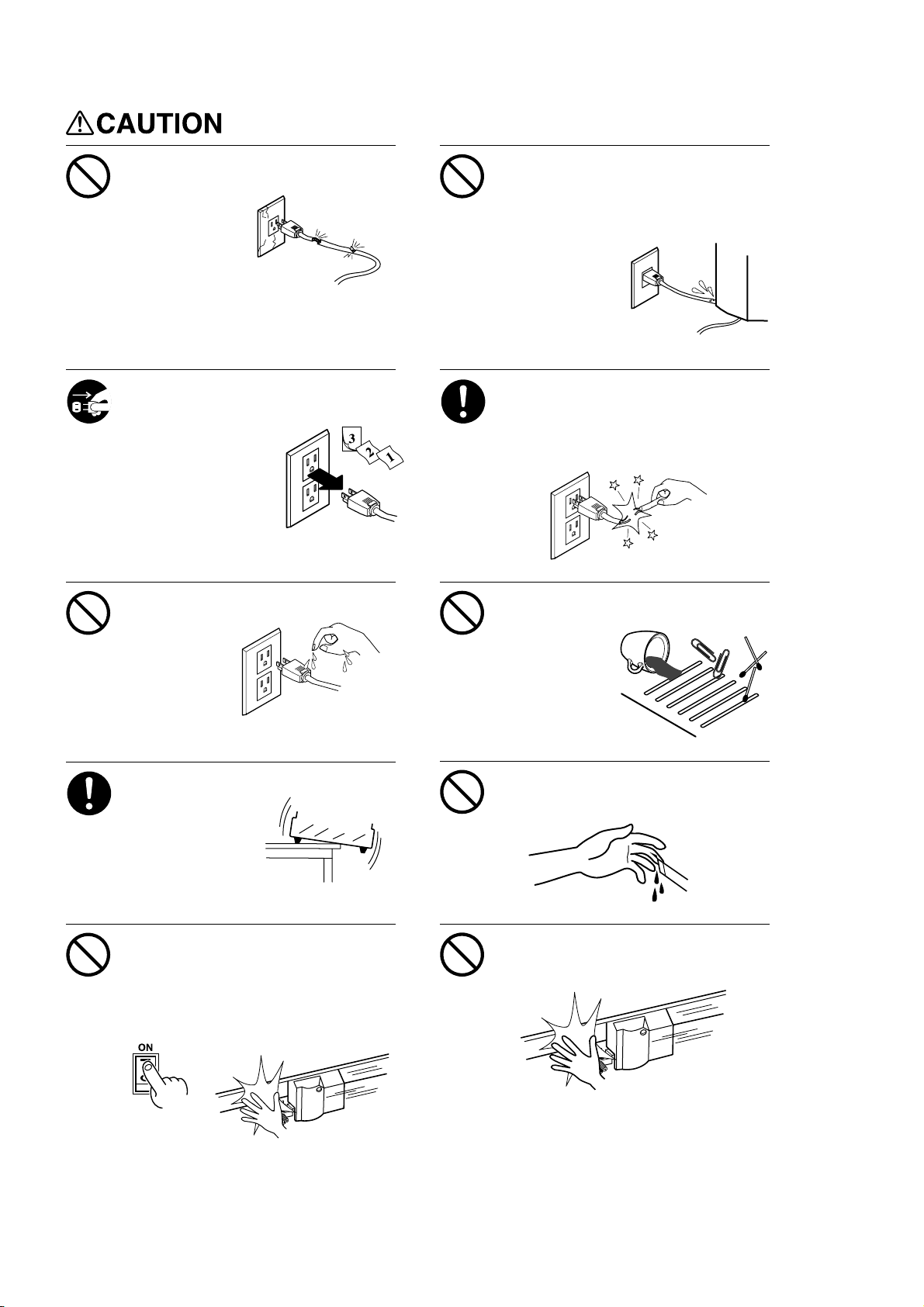
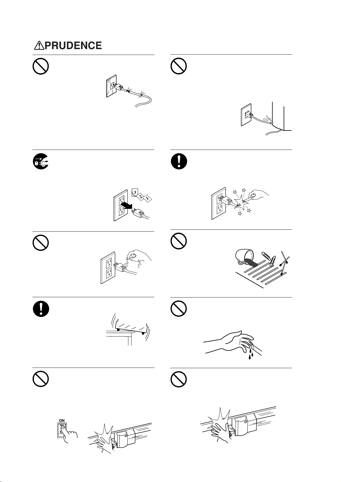
Do not use with a damaged power
cord or plug, or with a loose
electrical outlet.
Use with any other
power supply may
lead to fire or
electrocution.
Do not injure or modify the electrical
power cord, nor subject it to
excessive bends, twists, pulls,
binding, or pinching, nor place any
object of weight on it.
Doing so may
damage the
electrical power
cord, leading to
electrocution or
fire.
When not in use for extended
periods, unplug the power cord from
the electrical outlet.
Failure to do so may
result in danger of
shock, electrocution,
or fire due to
deterioration of the
electrical insulation.
Do not attempt to unplug the power
cord with wet hands.
Doing so may
result in electrical
shock.
Install on a stable surface.
Failure to do so
may result in
falling of the unit,
leading to injury.
When unplugging the electrical
power cord from the power outlet,
grasp the plug, not the cord.
Unplugging by pulling the cord may damage
it, leading to fire or electrocution.
Do not allow liquids, metal objects
or flammables inside the machine.
Such materials
can cause fire.
Do not touch the tip of the blade
with your fingers.
Doing so may result in injury.
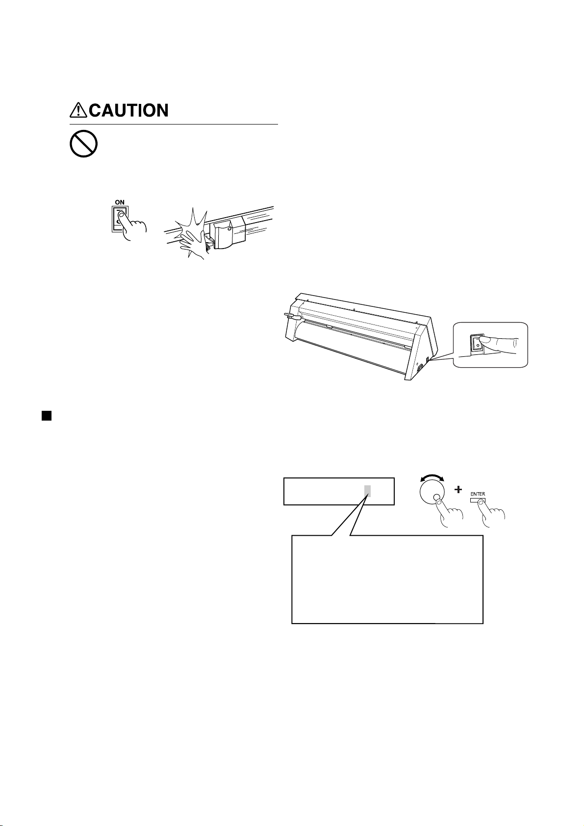
Do not place the hands or anything
else on the platen when switching
on the power.
Doing so may result in injury.
(The cutting carriage moves simultaneously
when the power is switched on.)
Do not place hands near the platen
while in operation.
Doing so may result in injury.
4
Page 5
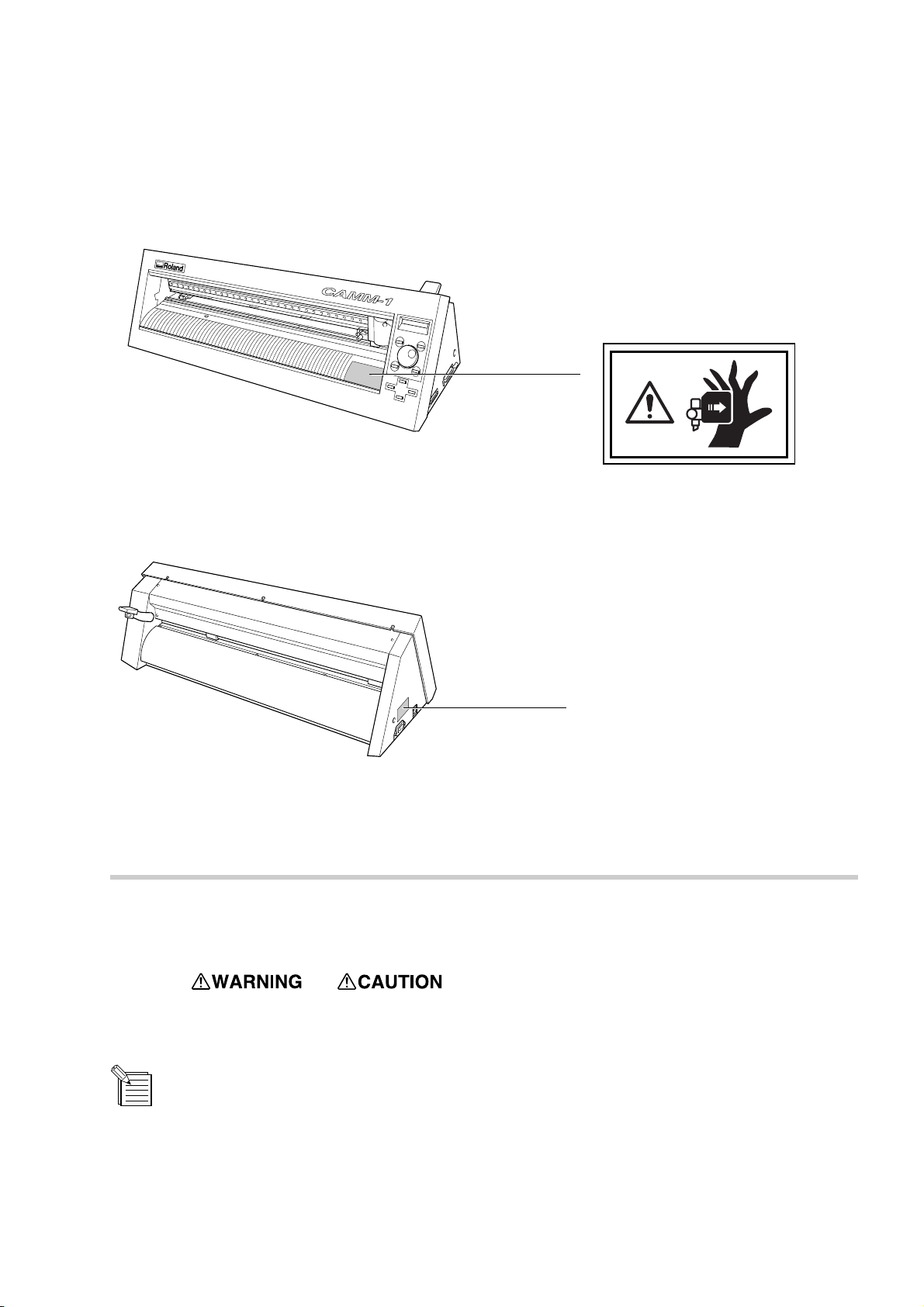
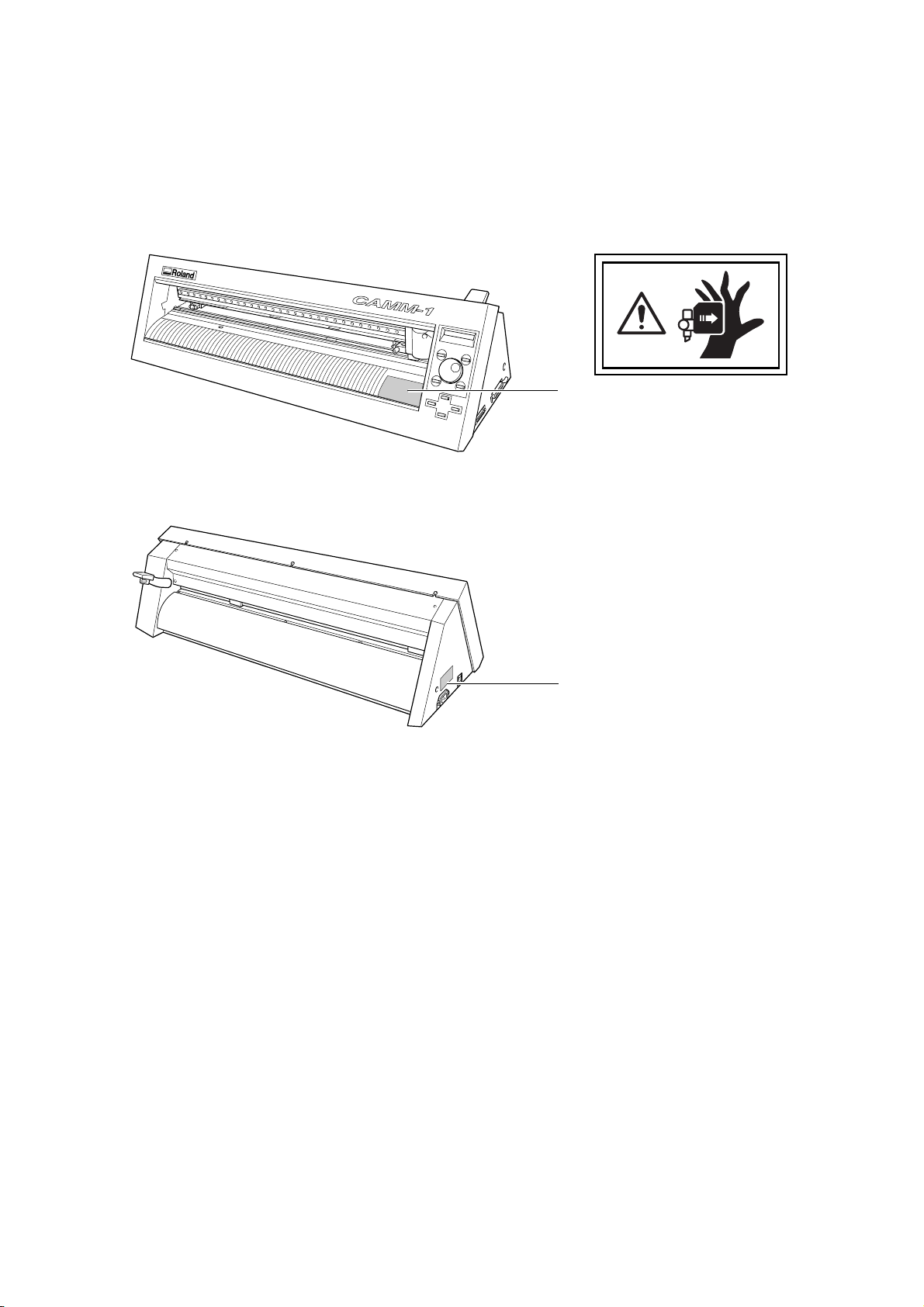
About the Labels Affixed to the Unit
These labels are affixed to the body of this product.
The following figure describes the location and content of these messages.
Do not place hands near the platen
while in operation.
In addition to the
NOTICE
: Indicates information to prevent machine breakdown or malfunction and ensure correct use.
: Indicates a handy tip or advice regarding use.
Model name
Rating label
Use a rated power supply.
and symbols, the symbols shown below are also used.
5
Page 6
Pour utiliser en toute sécurité
Avis sur les avertissements
Utilisé pour avertir l'utilisateur d'un risque de décès ou de blessure grave en
cas de mauvaise utilisation de l'appareil.
Utilisé pour avertir l'utilisateur d'un risque de blessure ou de dommage
matériel en cas de mauvaise utilisation de l'appareil.
* Par dommage matériel, il est entendu dommage ou tout autre effet
indésirable sur la maison, tous les meubles et même les animaux
domestiques.
À propos des symboles
Le symbole attire l'attention de l'utilisateur sur les instructions importantes ou les
avertissements. Le sens précis du symbole est déterminé par le dessin à l'intérieur du triangle.
Le symbole à gauche signifie "danger d'électrocution".
Le symbole avertit l'utilisateur de ce qu'il ne doit pas faire, ce qui est interdit. La chose
spécifique à ne pas faire est indiquée par le dessin à l'intérieur du cercle. Le symbole à
gauche signifie que l'appareil ne doit jamais être démonté.
Le symbole prévient l'utilisateur sur ce qu'il doit faire. La chose spécifique à faire est
indiquée par le dessin à l'intérieur du cercle. Le symbole à gauche signifie que le fil électrique
doit être débranché de la prise.
Ne pas démonter, réparer ou
modifier.
Le non-respect de cette consigne pourrait
causer un incendie ou provoquer des
opérations anormales entraînant des
blessures.
Mettre l'appareil à la masse avec une
prise de terre.
Le non-respect de cette consigne pourrait
entraîner des décharges électriques en
cas de problème mécanique.
Ne pas utiliser avec une alimentation
électrique non conforme à la norme
indiquée sur l'appareil.
Une utilisation avec toute autre alimentation
électrique pourrait provoquer un incendie
ou une électrocution.
Ne pas utiliser si l'appareil est dans
un état anormal (c'est-à-dire s'il y a
émission de fumée, odeur de brûlé,
bruit inhabituel etc.).
Le non-respect de cette consigne pourrait
provoquer un incendie ou des décharges
électriques.
Éteindre l'appareil immédiatement,
débrancher le fil électrique de la prise et
communiquer avec le revendeur autorisé
Roland ou le centre de service.
Utiliser l'appareil uniquement avec le
fil électrique fourni.
Utiliser l'appareil avec un autre fil risque de
provoquer un incendie ou une électrocution.
6
Page 7
Ne pas utiliser avec une fiche ou un
fil électrique endommagé ou avec
une prise mal fixée.
Une négligence à
ce niveau pourrait
provoquer un
incendie ou une
électrocution.
Ne pas endommager ou modifier le
fil électrique. Ne pas le plier, le
tordre, l'étirer, l'attacher ou le serrer
de façon excessive. Ne pas mettre
d'objet ou de poids dessus.
Une négligence à
ce niveau pourrait
endommager le fil
électrique ce qui
risquerait de
provoquer une
électrocution ou un
incendie.
Débrancher le fil lorsque l'appareil
reste inutilisé pendant une longue
période.
Une négligence à ce niveau pourrait
provoquer des décharges électriques,
une électrocution ou
un incendie dû à une
détérioration de
l'isolation électrique.
Ne pas essayer de débrancher le fil
avec des mains mouillées.
Une négligence à
ce niveau pourrait
provoquer des
décharges
électriques.
Installer l’appareil sur une surface
stable.
Une négligence à
ce niveau pourrait
provoquer la chute
de l’appareil et
entraîner des
blessures.
Saisir la fiche et non le fil électrique
lorsque vous débranchez.
Débrancher en tirant sur le fil pourrait
l'endommager et risquer de provoquer un
incendie ou une électrocution.
Ne pas introduire de liquide, d'objet
métallique ou inflammable dans
l'appareil.
Ce genre de
matériel peut
provoquer un
incendie.
Ne pas toucher l'extrémité de la
lame avec les doigts.
Une négligence à ce niveau pourrait
provoquer des blessures.
Ne pas mettre les mains ni quoi que
ce soit sur le coulisseau au moment
de mettre sous tension.
Une négligence à ce niveau peut provoquer
des blessures.
(Le chariot de coupe se déplace lorsque
l'appareil est mis sous tension.)
Ne pas mettre les mains près du
coulisseau pendant le
fonctionnement de l'appareil.
Une négligence à ce niveau peut provoquer
des blessures.
7
Page 8
À propos des étiquettes collées sur l'appareil
Ces étiquettes sont collées à l'extérieur de l'appareil.
Les dessins suivants indiquent l'endroit et le contenu des messages.
Avant
N'approchez pas vos mains du
plateau de travail quand le chariot
est en mouvement.
Arrière
Nom du modèle
Étiquette des caractéristiques
électriques
Utiliser l'alimentation appropriée
8
Page 9
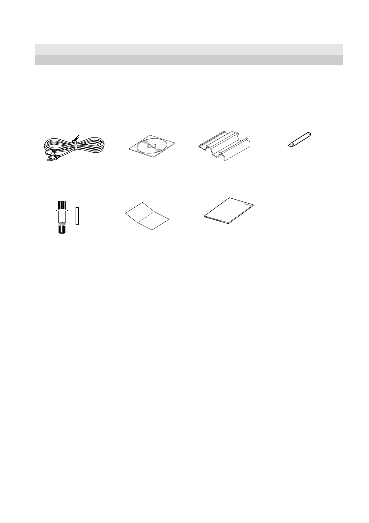
1 Checking Supplied Items
This product includes the items shown below.
Before starting use, make sure all the items are present.
1 Checking Supplied Items
Power cord: 1 Roland Software Package
CD-ROM: 1
Blade holder
(XD-CH3) : 1
Pin
Startup manual: 1 To Ensure Safe Use: 1
Roller base: 1 Blade: 1
* CX-24 only
9
Page 10
2 Part Names and Functions
2 Part Names and Functions
In explanations that are common for both the CX-24 and the CX-12, figures depicting the CX-24 are used.
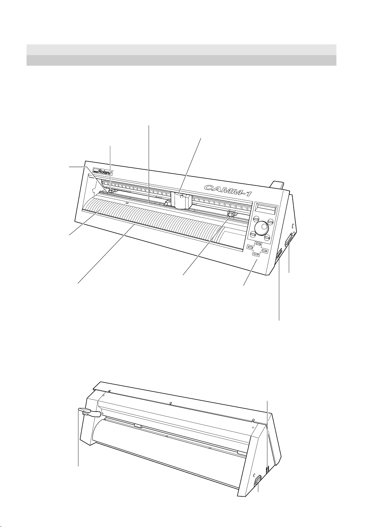
2-1 Front View
Pinch roller (Left)
This presses down on the material to hold it in place.
Set this at the left-hand edge
of the material.
Grit roller
This rotates to
feed the material
forward and
backward.
Guide line marks
The edges of the
material is aligned with
the lines when loading.
Knife guide
The commercially available
knife is inserted and slid across
this.
This makes it possible to separate a piece of material from the
roll while still loaded in place.
Blade protector
Pinch roller (Right)
This presses down on the
material to hold it in place.
Set this at the right-hand
edge of the material.
Cutting carriage
The blade holder (or
pen) is installed here.
Operation panel
Serial (RS-232C) Input Connector
This is for connecting a crossover serial (RS232C) cable (sold separately).
Parallel (Centronics)
Input Connector
This is for connecting a
printer cable (sold
separately).
2-2 Rear View
Sheet loading lever
This is for loading and unloading
material.
Power switch
Pressing the "|" side turns on the power.
Pressing the "O" side turns off the power.
Power connector (AC IN)
10
Page 11
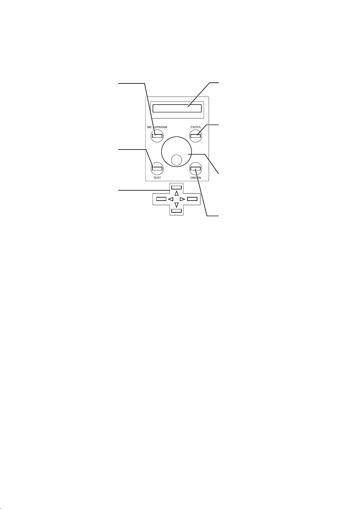
2-3 Operation Panel
2 Part Names and Functions
[MENU/PARAM] Key
This selects whether turning the dial
chooses menu items or changes
setting values.
Pressing this key changes the
location of the menu cursor.
[TEST] Key
This performs a cutting test. You can
use it to make sure that the blade
force is appropriate.
Position Key
This moves the blade (or pen) and
the material.
Display
This displays the various menus and setting
values, as well as error messages.
[ENTER] Key
This is used to choose menu items and confirm
settings.
Pressing it during operation pauses operation.
Dial
This is used to change menu items and settings.
[ORIGIN] Key
This sets the origin point at the present position
of the blade.
11
Page 12
3 Preparing the CX-24/12
3 Preparing the CX-24/12
3-1 Setting
NOTICE
Ground the unit with the ground
wire.
Failure to do so may result in risk of
electrical shock in the even of a mechanical
problem
Install on a stable surface.
Failure to do so
may result in
falling of the unit,
leading to injury.
Do not use with any electrical power
supply that does not meet the
ratings displayed on the unit.
Use with any other power supply may lead
to fire or electrocution.
Use only with the power cord
included with this product
Use with other than the included power cord
may lead to fire or electrocution.
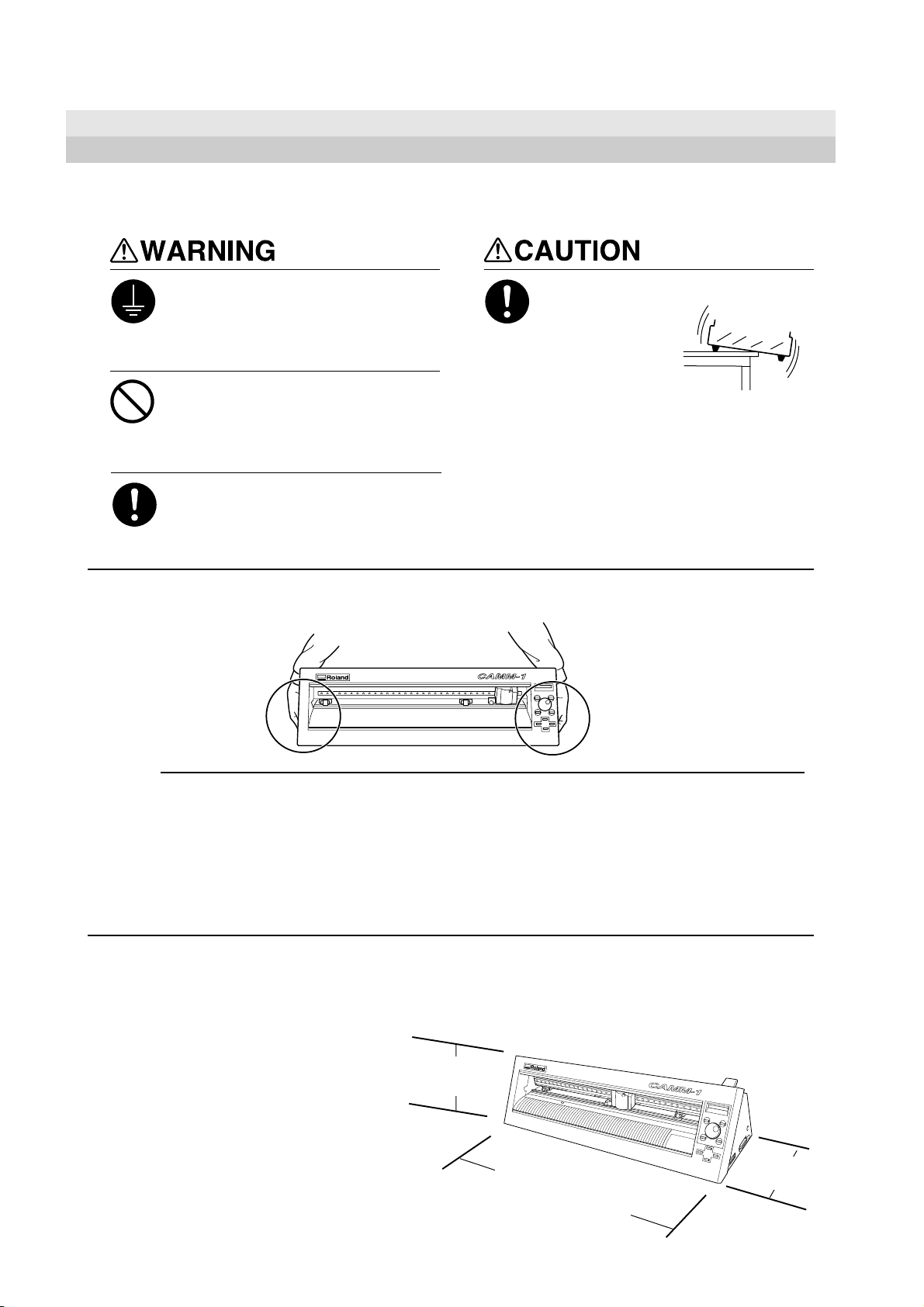
When moving the machine, do not attempt to lift or carry it by grasping the top portion of the machine. Lift and
carry the machine by holding it with your hands along the left and right sides of the machine.
Never install this unit in any of the following situations, as it could result in breakdown or faulty operation:
• Places where the installation surface is unstable or not level.
• Places with excessive electrical noise.
• Places with excessive humidity or dust.
• Places with poor ventilation, because the CX-24/12 generates considerable heat during operation.
• Places with excessive vibration.
• Places exposed to strong illumination or direct sunlight.
• Install at least 1 m (39-3/8 in. ) away from a strong indoor lighting source.
Make sure the unit is placed on a stable, sturdy surface.
Installing requires the space shown below.
CX-24
950 mm (37-7/16 in.) wide, 500 mm (19-11/16 in.) in
depth, and 300 mm (11-13/16 in.) in height.
CX-12
650 mm (25-5/8 in.) wide, 500 mm (19-11/16 in.) in
depth, and 300 mm (11-13/16 in.) in height.
The material moves during cutting. Do not place
obstacles that may obstruct the material at the front and
rear of the machine.
300 mm
(11-13/16 in.)
CX-24: 950 mm (37-7/16 in.)
CX-12: 650 mm (25-5/8 in.)
500 mm
(19-11/16 in.)
12
Page 13
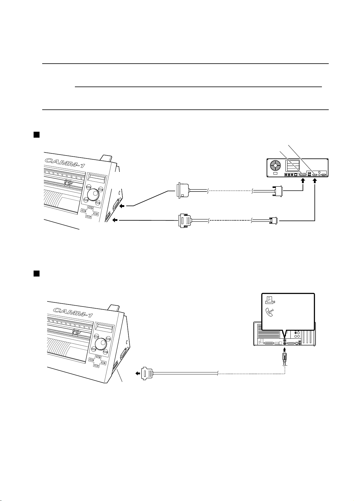
3-2 Connection
3 Preparing the CX-24/12
NOTICE
Connect the cable to either the parallel or the serial port. Be sure that the power to both the computer and the
main unit is switched off when connecting the cable.
Securely connect the power cord, computer I/O cable and so on so that they will not be unplugged and cause
failure during operation. Doing so may lead to faulty operation or breakdown.
For IBM PC or PC Compatibles
Parallel (Centronics)
Input Connector
Serial (RS-232C) Input
Connector
RS-232C connector on the computer
Printer connector on the computer
Parallel (Centronics) cable
Serial (RS-232C) cable
Cables are available separately.
One which you are sure
matches the model of computer
being used should be selected.
For Macintosh
Serial Input Connector
Printer Port
Modem Port
Connect to either port.
Crossover serial cable
Cables are available separately.
13
Page 14
3 Preparing the CX-24/12
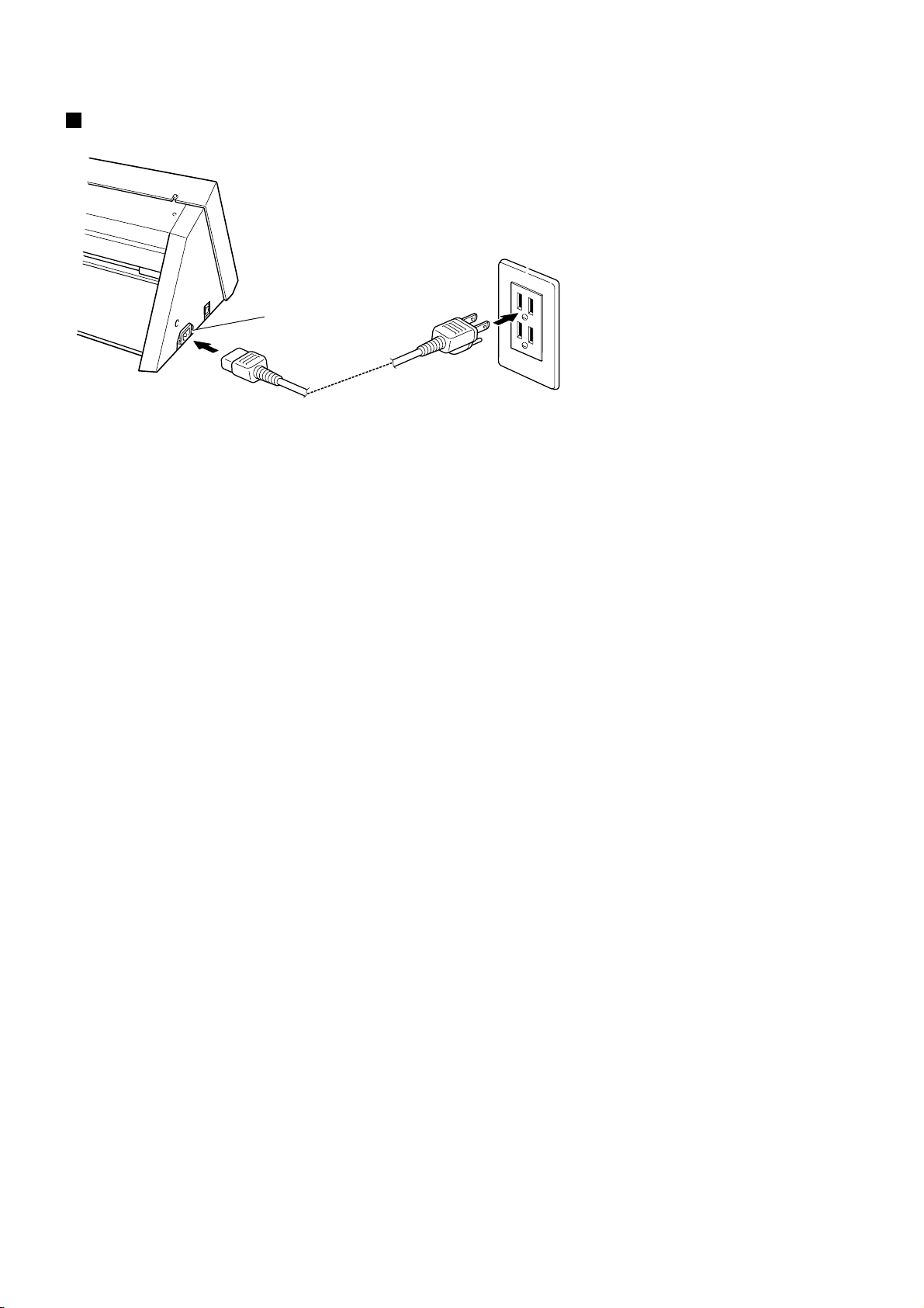
Connecting the Power Cord
Power connector
Power cord
Power outlet
3-3 Installing the Driver
The included Roland Software Package CD-ROM contains a Windows-based program and driver for performing cutting with the CX-24/
12.
CAMM-1 DRIVER
This software is required when sending data from a Windows-based program to the CX-24/12. If you're using Windows, be sure to install
this driver.
Refer to the included Startup Manual and install them on your computer.
14
Page 15
3 Preparing the CX-24/12
3-4 Port Setting
The CX-24/12 automatically detects the port used for connection to the computer.
However, if cutting data is not sent correctly, check the communication parameters for the driver and use the display menu on the CX-24/
12 to make the same settings as for the driver.
Checking the Communication Parameters for the Port and Driver
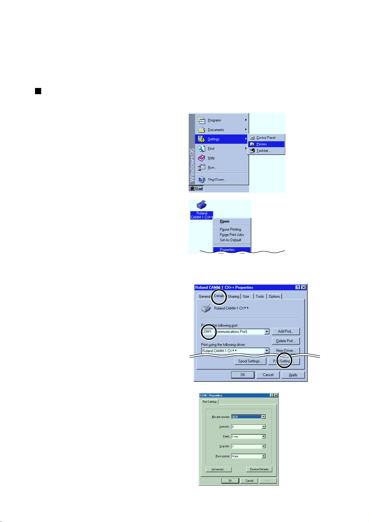
- Windows 95/98/Me
Click [Start].
1
Point to [Settings] and click [Printers].
The [Printers] folder appears.
Right-click on the icon for the driver of the model
you're using then click [Properties].
2
The [Roland CAMM-1 CX** **Properties] dialog
box appears.
For the CX-24:
[Roland CAMM-1 CX-24]
For the CX-12:
[Roland CAMM-1 CX-12]
The Properties dialog box for the model you’re using
appears.
Make sure the port connected to the CX-24/12
appears under [Print to the following port].
3
When the connection uses a serial cable, click [Port
Settings].
The Properties dialog box for the connected port
appears.
Check the communication parameters for the driver.
4
15
Page 16
3 Preparing the CX-24/12
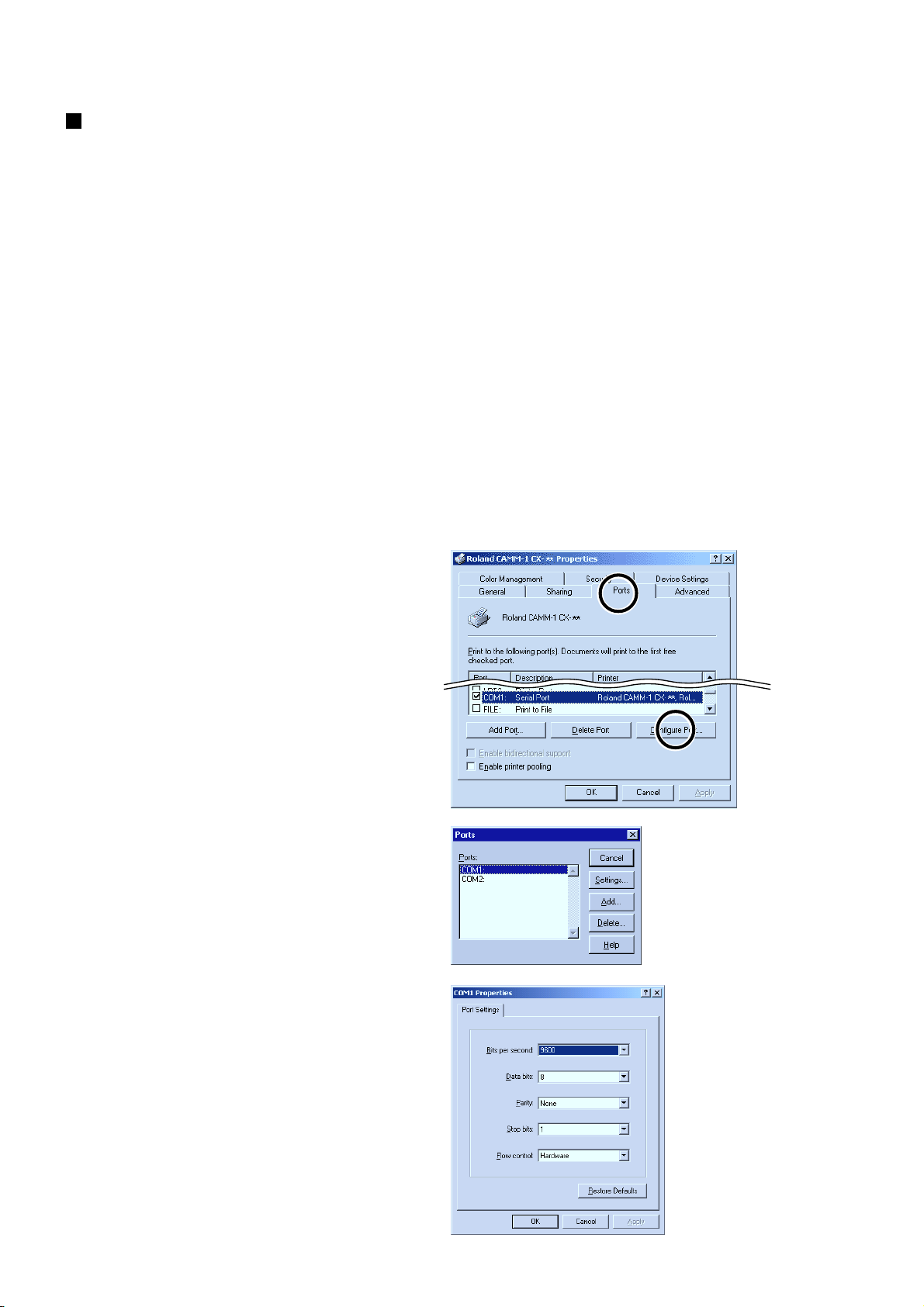
Checking the Communication Parameters for the Port and Driver
- Windows NT 4.0/2000/XP
If you are installing under Windows 2000/XP or Windows NT 4.0, you need full access permissions for the printer settings.
Log on to Windows as a member of the "Administrators" or "Power Users" group.
(For more information about groups, refer to the documentation for Windows.)
The descriptions of the following procedures use screen shots from Windows 2000.
Click [Start].
1
Point to [Settings] and click [Printers].
If you’re using Windows XP, click [Start]-[Control
Panel] and then click [Printers and Other Hardwares]-
[Printers and Faxes].
The [Printers] folder appears.
Right-click on the icon for the driver of the model
2
you're using then click [Properties].
For the CX-24:
[Roland CAMM-1 CX-24]
For the CX-12:
[Roland CAMM-1 CX-12]
The Properties dialog box for the model you’re using
appears.
Click the [Ports] tab. Make sure the port connected to
3
the CX-24/12 appears under [Print to the following
port].
When the connection uses a serial cable, click
[Configuration Port].
If you're using Windows 2000/XP, the Properties
dialog box for the connected port appears. Skip to
step 5.
If you're using Windows NT 4.0, the [Serial Port]
dialog box appears. Go to step 4.
Click the port you chose in step 3, then click [Set-
4
tings].
The dialog box for the connected port appears.
Check the communication parameters for the driver.
5
16
Page 17
3 Preparing the CX-24/12
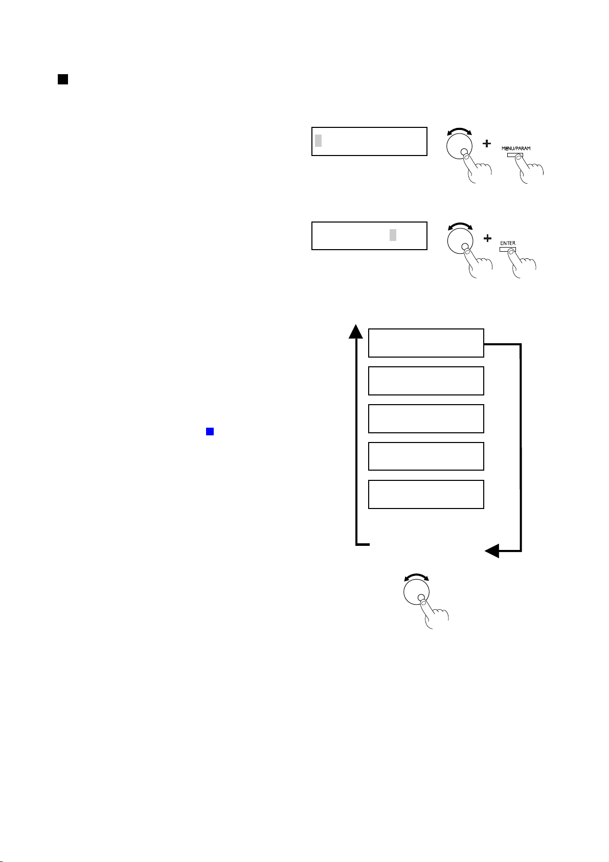
Making the Settings from the Menu on the CX-24/12
The display menu can only be used to make settings when material is loaded and set up. Before attempting to make menu settings, refer
to "4-3 Turning on the Power" and put the CX-24/12 in a setup state.
Turn the dial to display the screen shown at right.
1
Press the [MENU/PARAM] key.
Turn the dial to display the port where the cable is
connected, then press the [ENTER] key to confirm
2
the setting.
If you chose [SERIAL] in step 2, the screen for
setting the bit rate appears.
3
Turning the dial clockwise successively displays the
screens for setting the bit rate, data bit, stop bit, parity
checking, and hardware handshaking (flow control).
Turning the dial counterclockwise returns to the menu
in step 1 without making any changes.
At the screen where the setting items are displayed,
you can change the setting values by pressing the
[MENU/PARAM] key and turning the dial.
For more information about how to make settings, see
"4-3 Turning on the Power -
Settings with the Control Panel."
Making Menu
I/O | <AUTO>
I/O | <AUTO>
Back to the screen in step 1
#BAUD.| <9600>
#DATA.| <8>
#STOP.| <1>
#PARITY| <NONE>
Turned
clockwise
#HANDS.|<H-WIRE>
Turned counterclockwise
17
Page 18
4 Basic Operation
4 Basic Operation
4-1 Installing a Blade
Do not touch the tip of the blade
with your fingers.
Doing so may result in injury.
NOTICE
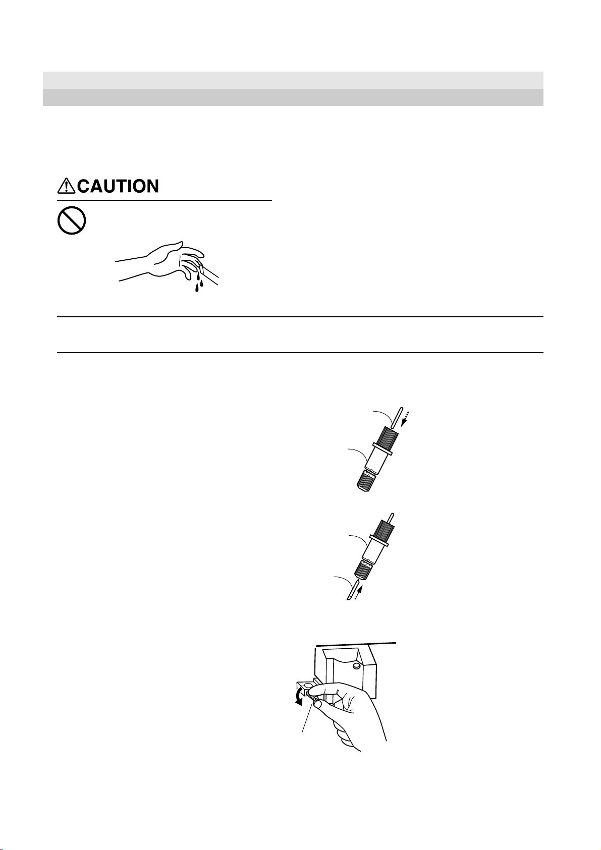
Insert a pin into the blade holder.
Be sure to support the tool mounting screw from below when installing the blade holder.
Cutting quality may become poor if installed without supporting the screw in this way.
1
Insert a blade into the blade holder.
2
Pin
Blade holder
Blade holder
Blade
Loosen the screw shown in the figure.
3
Screw
18
Page 19
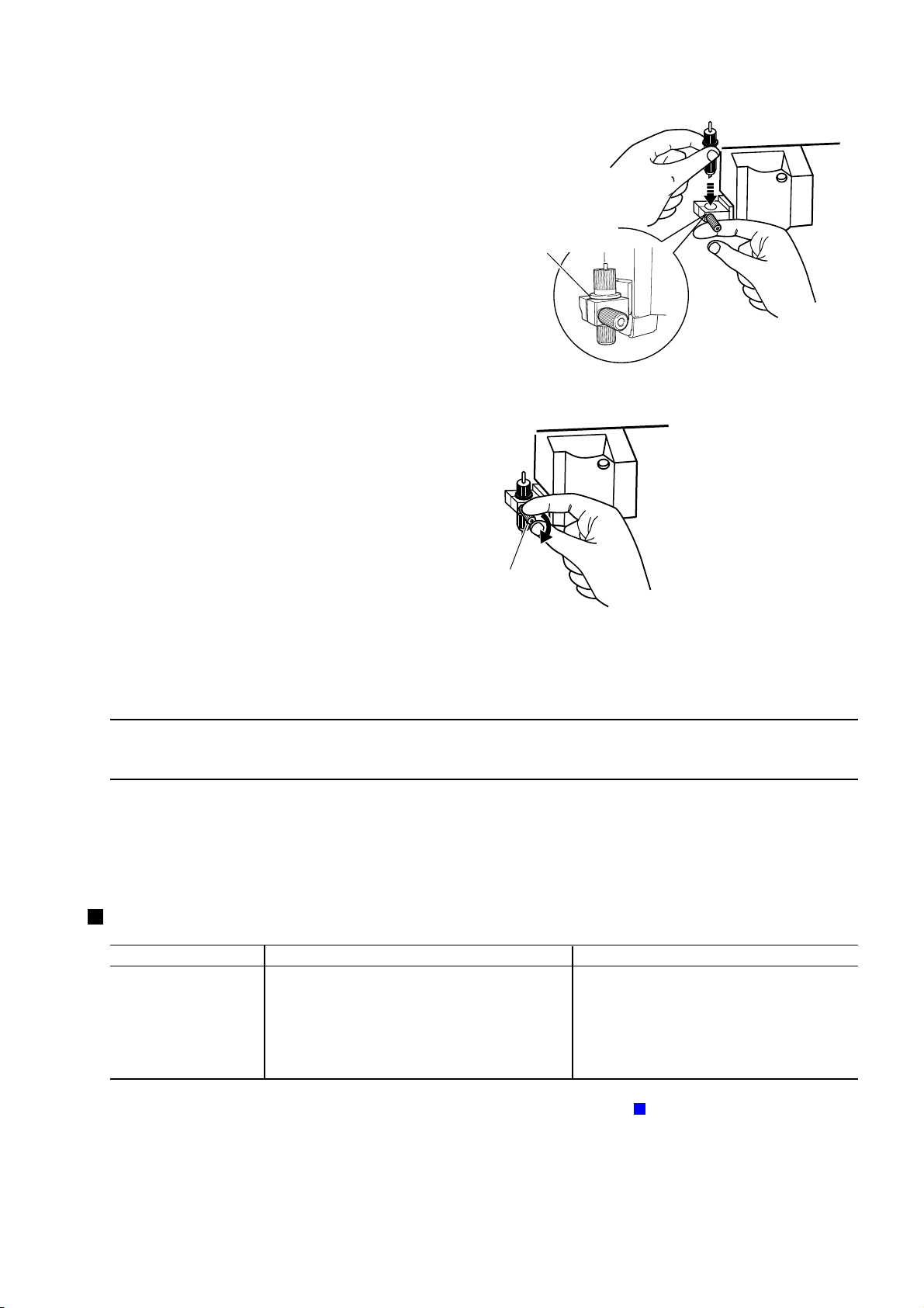
While supporting the screw from below, insert into
the blade holder from above.
4
Tighten the screw securely.
5
Tug the blade holder upward to make sure it does not
come loose.
4 Basic Operation
Insert until the collar of
the blade holder touches
the rim of the hole.
Screw
4-2 Loading the Material
NOTICE
On the CX-24, use the control panel to choose the configuration of the loaded material.
On the CX-12, there is no menu for choosing the configuration of the material.
Acceptable Material Sizes
(horizontal dimension)
Length
(vertical direction)
Do not use excessive force when moving the sheet loading lever.
Doing so may damage it.
CX-24
Width
50 to 700 mm (1-15/16 to 27-3/4 in.)
For flat material, 100 mm or more; for roll material,
no restriction
No other restrictions (* Accuracy assured within a
range of up to 1,600 mm (63 in.))
CX-12
50 to 395 mm (1-15/16 to 15-1/2 in.)
No restrictions (* Accuracy assured within a
range of up to 1,600 mm (63 in.))
For more information about the range in which cutting is possible, see "9-2 About the Materials -
19
About the Cutting Area."
Page 20
4 Basic Operation
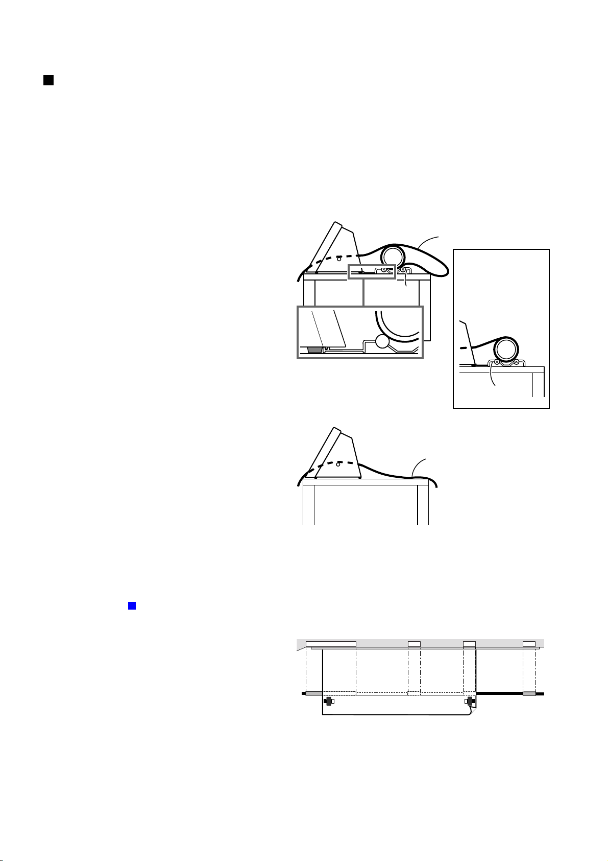
Loading the Material
Before you load material, make sure the sheet loading lever is lowered.
- If you are using roll material, start with step 1.
- If you are using piece material, start with step 2.
Pass the end of the material between the pinch rollers
1
and the grit rollers so that it extends from the front of
the unit.
- If You Are Using the Roller Base
On the CX-24, use the roller base. On the CX-12,
either see "- If You Are Not Using the Roller Base,"
or secure in place roll material as a substitute for the
roller base.
Roller Base
Pull out the portion
to cut from the roll.
When loaded as
shown in the figure,
correct feed cannot
be performed.
2
- If You Are Not Using the Roller Base
Position the material so that both edges are above the
grit rollers.
For more information about the width of the material
and the positions of the grit rollers, see "9-2 About the
Material -
- CX-24
When viewed from the front, align so that the
right-hand edge of the material is above any of
the grit rollers and the left-hand edge is above the
long grit roller.
Acceptable Material W idths."
Roller Base
Separate the necessary length for
cutting from the roll.
The white areas of the rails serve as a guide for positioning
the grit rollers.
For material with a width of 150 mm (6 in.) or less, place the
material above the grit roller at the left edge.
20
Page 21
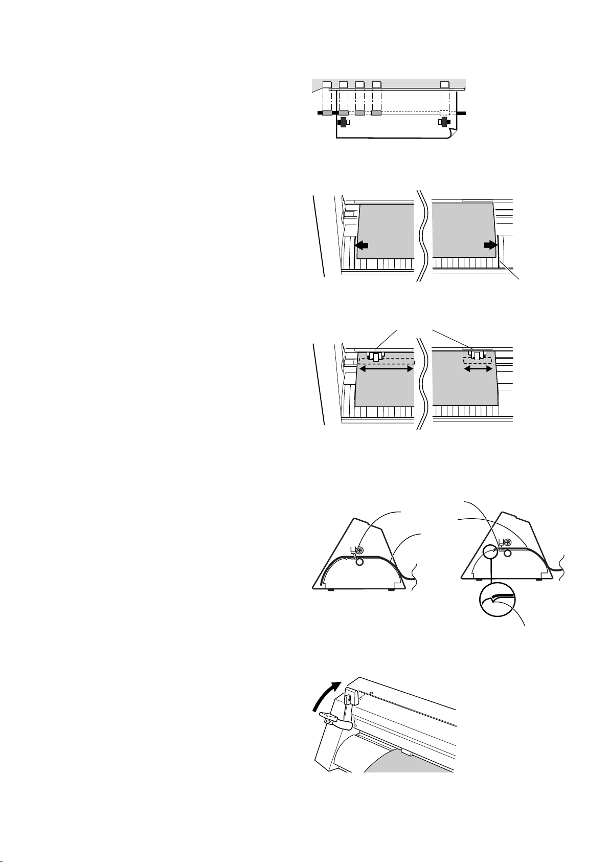
- CX-12
Position the material so that the left and right
edges are each above one of the grit rollers.
Align so that the left and right edges of the material
are parallel with the guide lines.
3
4 Basic Operation
The white areas of the rails serve as a guide for positioning
the grit rollers.
Guide line marks
Using the stickers on the rails as a guide, adjust the
positioning of the left and right pinch rollers above
4
the grit rollers.
Make sure the end of the material has been pulled out
farther toward the front than the blade protector.
5
OK
Stickers
Not OK
Blade protector
Material's edge
Raise the sheet loading lever.
This lowers the pinch rollers to hold the material in
6
place.
Make sure the end of the material
does not catch on this groove.
21
Page 22
4 Basic Operation
4-3 Turning on the Power
Do not place the hands or anything
else on the platen when switching
on the power.
Doing so may result in injury.
(The cutting carriage moves simultaneously
when the power is switched on.)
Turn on the CX-24/12.
Putting the Machine in the Setup State
Use the control panel to put the CX-24/12 in the setup state (the state for receiving data).
For the CX-24:
Turn the dial.
When the display shows the type of load material,
1
press the [ENTER] key.
The cutting carriage starts to move.
SELECT | ROLL
ROLL: Roll material
EDGE: When performing cutting from the
front edge of the material
PIECE: Flat material such as standard-
size and piece material
22
Page 23
The width of the material is detected and the unit is
made ready for cutting.
2
* When flat material is loaded, the material moves
to the front and rear to detect the length of the
material as well.
At this time, if the material is crooked and looks
like it might come loose from the pinch rollers, or
actually does come loose, reload the material.
For the CX-12:
4 Basic Operation
Press the [ENTER] key.
1
The cutting carriage starts to move.
The width of the material is detected and the unit is
2
made ready for cutting.
SETUP -> ENTER
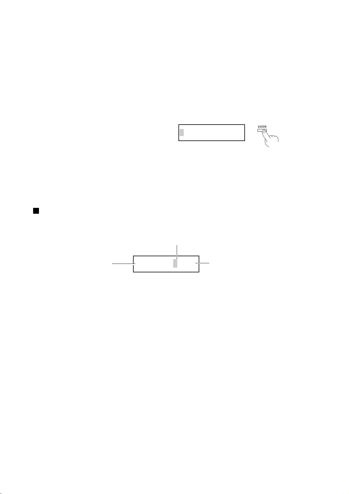
Making Menu Settings with the Control Panel
How to View the Display
Press the [MENU/PARAM] key to change the
location of the cursor.
This is the menu item.
When the cursor is on the left
side, turning the dial cycles
through the menu items.
OFFSET| <0.250>
This is the setting value for the menu item
appearing on the left side.
When the cursor is on the right side, turning the dial
changes the setting value. Press the [ENTER] key to
confirm the setting.
23
Page 24

4 Basic Operation
4-4 Checking Material Feed
Make sure that the material does not come loose from the pinch rollers while cutting is in progress.
On the CX-24, when you choose [PIECE] as the material type, the material is moved forward and backward in order to detect the length
of the material.
There is no need to perform the steps described below in order to make sure that the material does not come loose at this time.
Turn the dial to display the screen shown at right.
Press the [MENU/PARAM] key.
1
This displays the menu for setting the material-feed
length.
Turn the dial to change the value to the required
length of material for cutting. When the display
2
shows the desired value, press the [ENTER] key.
The display changes to the menu for performing
material feed.
When the screen shown at right appears, press the
[ENTER] key again.
3
A length of material corresponding to the setting you
made in step 2 is fed out.
If the material is crooked and looks like it might come
loose from the pinch rollers, or actually does come
loose, please reload the material.
* To perform material feed using the value dis-
played in step 1, then after step 2, simply press
the [ENTER] key, and material feed is performed.
AREA |< 1.0m>
AREA | < 1.0m>
AREA | MOVE
24
Page 25

4-5 When Performing Long Cutting
Cutting a length of 1.5 m (59 in.) or more requires
material that is at least 50 mm (2 in.) wider than the
necessary cutting width.
1.5 m (59 in.) or more
Prepare material that is at least
50 mm (2 in.) wider than the
necessary cutting width.
4 Basic Operation
Refer to the figure at right and move the pinch rollers.
Position the pinch rollers so that each one is 25 mm (1
1
in.) from the respective left or right edge of the
material.
Raise the sheet loading lever to secure the material in
2
place.
25 mm
(1 in.) or more
25 mm
(1 in.) or more
Before performing material feed, pull out the required
3
length of material from the roll material.
Refer to the previous section, "4-4 Checking Material
4
Feed," and perform material feed.
If the material comes loose, then reload the material.
25
Page 26

4 Basic Operation
4-6 Setting the Origin Point
Loading material and pressing the [ENTER] key automatically sets the origin point for cutting.
The origin point set when you do this varies according to model and the shape of the selected material.
Model
CX-24
CX-12
CX-24/12, in addition to the foregoing locations, you can freely set the origin point (0, 0) anywhere in the cutting area.
Setting the origin point at an uncut area of the material lets you use the material with less waste.
To set the origin point where you want, follow the steps below.
Before setting the origin point, load the material.
Refer to "4-2 Loading the Material" and load the
1
material.
Use the position keys to move the center of the blade
2
holder to the location where you want to set the origin
point.
Material shape selected from the menu
[ROLL]
[EDGE]
[PIECE]
There is no material-selection menu.
- Near the left pinch roller
- Near the right pinch roller when the [ROTATE] menu
item is set to ON
- At the front lower left of the material
- Near the front lower right of the material when the
[ROTATE] menu item is set to ON
- Near the left pinch roller
- Near the right pinch roller when the [ROTATE] menu
item is set to ON
Location of the origin point
Press the [ORIGIN] key. The message [ORIGIN
SETTING] flashes on the display, and the origin point
3
is set.
ORIGIN SET
26
Page 27

4 Basic Operation
4-7 Performing a Cutting Test (How to Adjust Blade
Force/Adjusting the Cutter Blade)
Before carrying out actual cutting, you may wish to perform a "cutting test" to check whether the unit produces the cutout satisfactorily.
This is done by examining the results of the cutting test, and adjusting the blade force and the amount of blade extension. The cutting test
should be repeated until the appropriate cutting conditions for the material in use are discovered.
If smooth cutting cannot be performed, use the display menu to adjust the blade force.
If adjusting the blade force does not produce good cutting results, then adjust the amount of blade extension from the blade holder.
Cutting Test
If a material has not yet been loaded, then refer to "4-2 Loading the Material" to load the material correctly.
Use the position keys to move the blade holder.
Move to the position where the cutting test is to be
1
performed.
Press the [TEST] key for 0.5 seconds or more.
2
The shape shown in the figure at right is cut at the
present location of the blade.
3
Peel off the material to check the result of the cutting
test.
If the results are not as described in step 3, use the
control panel to gradually raise the blade force.
4
* Note that an area of approximately 2 square
centimeters (a little less than a square inch) is
required to make a test cutout
Peel this off first.
The square should
remain, without
peeling off.
Peel this off next.
The blade should leave faint
traces on the base paper of the
material.
27
Page 28

4 Basic Operation
Adjusting the Blade Force
Turn the dial to display the screen shown at right.
Press the [MENU/PARAM] key.
1
The menu for setting the blade force appears.
Turn the dial clockwise to increase the blade force in
steps of 10 g.
2
When the display shows the desired value, press the
[ENTER] key.
When adjusting the blade force, take into account the
type and thickness of the material you are using, and
3
the hardness of the blade. (See "9-1 Blade and
Material Combinations.")
If the adjustment of the blade force is not correct, the
symptoms shown at right may occur.
FORCE | < 80g>
FORCE | < 80g>
Too large
Too small
- The material may be torn
- Blade life will be shortened
- Cutter blade extends through the
base paper, and normal advancing of the material becomes
impossible
- The CX-24/12 may be damaged.
- The material may not be cut
satisfactorily
Adjusting the Amount of Blade Extension
If cutting is not performed smoothly even after you have adjusted the blade force, then adjust the amount of blade extension for the tip of
the blade extending from the blade holder.
If you're using the included material or an equivalent general material, then tighten the cap all the way to the top
(maximum amount of blade extension: 2.5 mm (0.0984 in.) ).
When cutting material having base paper that is thin with respect to the material (material thickness), or material
having no base paper, the amount of blade extension should be adjusted so that the blade does not cut through the base
paper.
Remove the blade holder.
1
Adjust the amount of blade extension a little at a time,
performing cutting tests to check the results.
2
When the cutting tests show that the blade leaves
faint traces on the backing paper, the amount of blade
extension is optimal.
Use the following as a guide for calculating the
amount of blade extension.
Amount of
cutter blade
extension
Thickness of
=+
the material
portion
Thickness of
the base paper
2
Min. : 0 mm
0.1 mm
Turning the tip by an amount
corresponding to one large
scale gradation extends the blade
by 0.1 mm (0.00394 in.).
Adjustment for 0.5 mm (0.0197
in.) can be made by rotating the
cap one full turn.
Max. : 2.5 mm
(0.0984 in.)
28
Page 29

4-8 Downloading Cutting Data
4 Basic Operation
NOTICE
Using the CX-24/12 to cut data created using a program requires the CAMM-1 driver.
The CAMM-1 driver is in the included Roland Software Package. For information on how to install it, take a look at the included Startup
Manual.
The explanations in this section assume that the CAMM-1 driver is already installed, and describe how to make the settings for the
cutting range and tool parameters.
When loading a flat material on the CX-12, be sure to use a flat material that is about 70 mm (2-13/16 in.)
longer than the vertical size of the cutting data. If data larger than the vertical length of the material is sent, the
CX-12 will attempt to cut the data even if it does not all fit in the material. This means that the material is
dislodged from the grit roller, and cutting continues with no material. This can cause not only breakage to the
blade but also damage to the unit, and adequate care is required to prevent this.
If the material becomes dislodged or there is a problem in operation, then immediately press the [ENTER] key
or turn off the power switch on the left side of the machine.
The cutting range is determined by the positioning of the pinch rollers. Set the cutting range for the driver so
that it fits within this range.
If a size that is identical to the load material is specified and data is laid out accordingly, there may be portions
which cannot be cut.
:Cutting area
:Pinch roller
The range that can be cut changes according to the positioning of the pinch rollers. If you're using flat material,
use the program to specify a value that is about 70 mm (2-13/16 in.) shorter than the vertical size of the
material. For more information about the cutting range, see "9-2 About the Materials -
Area."
About the Cutting
29
Page 30

4 Basic Operation
Making the Settings for the CAMM-1 Driver -Windows 95/98/Me
In the program you're using, from the [File] menu,
choose [Print Setup] to display the [Printers] dialog
1
box.
* The names of the menu items may be different,
depending on the program you're using.
For the CX-24, choose [Roland CAMM-1 CX-24].
2
For the CX-12, choose [Roland CAMM-1 CX-12].
Click [Properties].
The [Properties] dialog box appears.
3
Click the [Size] tab and make the settings for the
cutting range at the screen shown at right.
4
Click the [Tools] tab.
5
Clicking the drop-down arrow displays the numerals
[1] through [8] and the [Machine Setting] selections.
To specify the speed for performing cutting using the
driver, choose a number from [1] to [8] and enter the
cutting conditions. When you do this, the machine
settings for the CX-24/12 are disabled.
To perform cutting using the conditions set with the
CX-24/12, choose [Machine Setting].
Click [OK].
In the [Printers] dialog box, click [OK].
6
In the program window, lay out the cutting data so
that it fits within the displayed cutting range.
* When you are performing cutting, clear the selection for [Fill Pitch].
Send the cutting data from the program to the CX-24/
7
12.
30
Page 31

4 Basic Operation
Making the Settings for the CAMM-1 Driver -Windows NT 4.0/2000/XP
If you are installing under Windows 2000/XP or Windows NT 4.0, you need full access permissions for the printer settings.
Log on to Windows as a member of the "Administrators" or "Power Users" group.
(For more information about groups, refer to the documentation for Windows.)
The descriptions of the following procedures use screen shots from Windows 2000.
In the program you're using, from the [File] menu,
choose [Print Setup] to display the [Printers] dialog
1
box.
* The names of the menu items may be different,
depending on the program you're using.
For the CX-24, choose [Roland CAMM-1 CX-24].
2
For the CX-12, choose [Roland CAMM-1 CX-12].
Click [Properties].
The [Properties] dialog box appears.
3
For Windows 2000/XP, click [Advanced].
For Windows NT 4.0, click [Advanced] tab.
4
Click the [MediaSizeSettings] document option at the
5
screen shown at right.
For Windows 2000/XP, click [Properties].
For Windows NT 4.0, click [Media Size Settings].
The [Media Size Settings] dialog box appears.
Click [Add New Media Size], then for [Media Size],
6
enter cutting range for [Width] and [Length].
Enter the [Media Size Name], then click [OK].
7
* For [Media Size Name], use only alphanumeric
characters.
31
Page 32

4 Basic Operation
Click [Selected Tool] displays the numerals [1]
8
through [4] and the [Machine Setting] selections.
To perform cutting using the conditions set with the
CX-24/12, choose [Machine Setting].
To specify the speed for performing cutting using the
9
driver, choose a number from [1] to [4]. Double-click
the selected tool number, then enter the value for
[Tool Speed].
When you do this, the machine settings for the CX24/12 are disabled.
Click [OK].
If you're using Windows 2000/XP, the [Properties]
dialog box appears. Click [OK].
If you're using Windows NT, the [Printers] dialog box
appears.
Click [OK].
10
In the program window, lay out the cutting data so
that it fits within the displayed cutting range.
* When you are performing cutting, choose [Off] for [Fill Pitch].
Send the cutting data from the program to the CX-24/
11
12.
Pausing Cutting Operations
Pressing the [ENTER] key displays a screen like the one shown below and pauses cutting.
PAUSE | <CONT.>
- To resume cutting without change
Press the [PAUSE] key again.
32
Page 33

- To stop cutting
Halt transmission of cutting instructions from the computer.
Click [Start].
1
Point to [Settings] and click [Printers].
If you’re using Windows XP, click [Start]-[Control
Panel] and then click [Printers and Other Hardwares][Printers and Faxes].
Double-click the printer icon.
For the CX-24:
2
[Roland CAMM-1 CX-24]
For the CX-12:
[Roland CAMM-1 CX-12]
4 Basic Operation
From the [Printers] menu, click [Purge Print Jobs] or
3
[Purge Print Documents].
Make sure the displayed data for the file being printed
disappears.
If you're using Windows 2000/XP, choose [Cancel All
Documents].
Turn the dial on the CX-24/12 to choose [END].
4
Pressing the [ENTER] key displays the message
5
shown at right, and cutting stops.
PAUSE | <STOP>
SUSPENDED
When Continuing with Cutting on the Same Piece of Material
Set the origin point at an uncut location on the
material (the location where you want to cut next).
1
For information on how to set the origin point, see "4-
6 Setting the Origin Point."
Send the cutting data from the program to the CX-24/
12.
2
33
Page 34

4 Basic Operation
4-9 Applying the Completed Cutout
When cutting ends, affix the material you created.
- Before you affix the material, cleaning the location where you want to affix it to remove any dust or grease.
- When applying on a transparent medium such as window glass, it may be helpful to draw guide lines on the back
of the glass with a water-based pen (so that the lines can be wiped off after applying the material).
- If air bubbles are formed under the affixed material, use a needle to pop the bubble, then press out the air to
obtain a complete seal.
Removing the Material
Piece Material
Turn the dial to display the screen shown at right.
1
Press the [MENU/PARAM] key.
When the screen at right appears, press the [ENTER]
key.
2
The cutting carriage moves to the right.
Lower the sheet loading lever.
3
SETUP | <ON>
SETUP | ON->OFF
Remove the material.
4
34
Page 35

- For Roll Materials, or When Detaching Only a Cut Portion
Use the commercially available knife to sever the material along the
knife guide.
Knife Guide
Use tweezers to peel off unneeded portions of the
material you created.
1
* You should have weed boarders or rectangles
drawn around work to facilitate weeding.
4 Basic Operation
Stick application tape over the completed work.
2
Press down firmly on the application tape to remove
air bubbles. If you do not press firmly enough the cut
area will not stick to the surface.
Transfer the material you created to the application
tape.
3
Decide where to affix the material, then affix it,
4
making sure that it is not misaligned.
Rub over the application tape to make sure the work
is firmly stuck in place. Then peel off the application
tape.
35
Page 36

4 Basic Operation
4-10 When Cutting Is Completed
When not in use for extended
periods, unplug the power cord from
the electrical outlet.
Failure to do so may
result in danger of
shock, electrocution,
or fire due to
deterioration of the
electrical insulation.
NOTICE
Loosen the screw shown in the figure and remove the
1
blade holder from the cutting carriage.
Press the pin shown in the figure and detach the blade
holder.
2
If a blade was used, wipe the blade with a soft cloth
to remove any material that may cling to it.
Do not leave the tool mounting screws tightened. Tightening the screw makes it more difficult to install the
blade holder.
Screw
Pin
Blade holder
Blade
Lower the sheet loading lever then remove the
material.
3
Turn off the power.
4
* Use a soft, dry cloth to wipe down the CX-24/12.
36
Page 37

5 Performing a Self-Test
5 Performing a Self-Test
The CX-24/12 is equipped with a "self-test" function to conveniently allow you to check whether or not it is capable of operating
normally. If the CX-24/12 is not performing correctly, follow the steps below to perform a self-test.
A computer is not required in order to carry out the self-test.
Refer to "4-1 Installing a Blade" and install the blade
holder to the cutting carriage on CX-24/12.
1
Hold down the [ ] key on the panel while you turn
2
the power on.
Refer to "4-2 Loading the Material" and load the
material.
3
When the display shows the screen at right, press the
[ENTER] key to start the operation check.
4
Operations is normal if the figure shown at right is
cut.
CX-24 CX-12
SELECT | ROLL SETUP -> ENTER
37
Page 38

6 Plotting on Paper Media
6 Plotting on Paper Media
Before cutting, plotting using pen and paper can ensure that your design is correct without wasting materials.
This feature can also be used to plot template designs on thick materials that may not be able to cut.
* Since the design of the CX-24/12 differs inherently from that of dedicated plotters, it does not accommodate functions
such as high-speed plotting, automatic pen changes, pen dry protection, or the like.
Acceptable Pens and Paper Media
Acceptable paper : High-quality paper
Acceptable pens : Water-based fiber-tipped pens
Thick water-based fiber-tipped pens
Refer to "4-1 Installing a Blade" and install the pen
by following the same steps as for installing a blade.
1
Acceptable paper widths :
CX-24 50 to 700 mm (1-15/16 to 27-3/4 in.)
CX-12 50 to 395 mm (1-15/16 to 15-1/2 in.)
Refer to "4-2 Loading the Material" and load the
paper by following the same steps as for loading
2
material.
If you're using the CX-24, then when the menu for
selecting the type of material appears, choose
[PIECE].
Turn the dial to display the screen shown at right.
3
Press the [MENU/PARAM] key.
Turn the dial to display <0 (PEN)>, then press the
[ENTER] key.
4
When the plot data is sent from the computer, plotting
starts.
5
OFFSET| <0.250>
OFFSET| <0(PEN)>
38
Page 39

7 Repeating the Same Cutting
7 Repeating the Same Cutting
The CX-24/12 can store the data sent from the computer in a buffer (a temporary memory area), and use this data to repeat cutting.
In the setup state, when cutting data is sent, the data is buffered at the same time that cutting starts.
Data sent until the setup state is released can be recut.
- Even after the setup state is released, data for recutting does not disappear until new data is sent from the
computer.
- When the power is switched off, any existing data in the buffer is deleted.
- If the buffer becomes full while data is being sent, recutting cannot be performed.
When this happens, running [REPLOT] displays the message "DATA TOO LARGE."
- When there is no data in the buffer, the message "NO DATA" appears.
Preparing the Cutting Data
When you repeat cutting, all data in the buffer is called up and cut. Before you send data from the computer, delete all the data in the
buffer in the CX-24/12.
Turn the dial to display the screen shown at right.
1
Press the [MENU/PARAM] key.
Turn the dial to display <CLEAR>, then press the
[ENTER] key.
2
The data in the buffer is deleted.
Refer to "4-8 Downloading Cutting Data" and send
the cutting data from the computer.
3
REPLOT| START
REPLOT| CLEAR
39
Page 40

7 Repeating the Same Cutting
Getting Ready for Recutting
Repeating Cutting Without Replacing the Material
Use the position keys to move the blade holder to the
1
location for setting a new origin point.
Press the [ORIGIN] key to set the origin point.
2
Repeating Cutting on Different Material
Turn the dial to display the screen shown at right.
Press the [MENU/PARAM] key.
1
Turn the dial to display the screen shown at right.
2
Press the [ENTER] key.
The setup state is released.
Load the new material. For information on how to
3
load the material, see "4-2 Loading the Material."
Performing Recutting
Turn the dial to display the screen shown at right.
1
Press the [MENU/PARAM] key.
SETUP | <ON>
SETUP | ON->OFF
REPLOT| START
Press the [ENTER] key.
2
Recutting starts.
REPLOT| START
40
Page 41

8 Cutting Printed Material
8 Cutting Printed Material
Making stickers and the like involves cutting around figures that have already been printed.
With the CX-24/12, sensors on the cutting carriage read guide marks printed on the material (crop marks) and use these to align the
positioning for printing and cutting.
You use the program to lay out the crop marks before creating the design.
8-1 Using Crop Marks
In order for the crop marks to be able to be read by the CX-24/12, the conditions below must be met.
- Data-creation Program
Use a drawing or PostScript program compatible with the CX-24/12.
Data from bitmap programs that work chiefly with images cannot be output with the CX-24/12.
The program must have functions that let you designate specific points as the reference for printing, and also that let you freely move
such designated points.
- Printer
Use a laser or inkjet printer.
Depending on the printer, however, the CX-24/12 may be unable to read printed crop marks.
A resolution of 720 dpi or higher is required.
Printers that smudge solid areas during printing produce crop marks that cannot be read.
- Materials
Use material that can be printed by a laser or inkjet printer and that meets the following conditions.
Material type: : Laser printers -> High-quality paper, coated paper, art paper, or PET
Inkjet printers -> High-quality paper or coated paper
Material thickness: about 0.2 mm
Color : White
Crop marks on laminated material cannot be read.
If the CX-24/12 cannot read crop marks or if printing and cutting are misaligned even when all the conditions have been fulfilled and
operations have been carried out correctly, the cause may be one of the following.
- Program accuracy
- Printer accuracy
- Expansion or contraction of the material due to ambient temperature or humidity
When unaffected by these factors, the alignment accuracy of the CX-24/12 is as follows.
±3 mm (0.12 in.) or less with 500 mm (19-5/8 in.) or less of
movement distance in the material-feed direction
8-2 Shape and Layout of Crop Marks
Shape of Crop Marks
Crop marks that can be read by the sensors must be circular
and have a diameter of 10 mm.
For the color density, specify 100% black.
41
10 mm
(0.39 in.)
Page 42

8 Cutting Printed Material
Crop Marks and Figure Layout
Place the crop marks at three locations, as shown in the figure below.
For sizes larger than A4For A4 size (portrait)
57 mm
(2-1/4 in.)
297 mm
(11-11/16 in.)
: Printable area
500 mm or less
(19-11/16 in.)
: There must be no soiling and
no figures other than crop
marks within this area.
55 mm (2-3/16 in.) or more
20 mm
(0.79 in.)
15 mm
(0.59 in.)
210 mm
(8-5/16 in.)
15 mm
(0.59 in.)
20 mm
(0.79 in.)
30 to 60 mm
CX-24: 610 mm (24 in.) or less
CX-12: 305 mm (12 in.) or less
(1-3/16 to 2-5/16 in.)
8-3 Loading the Material
Load the printed material on the CX-24/12 so that the crop marks are positioned as shown below.
Right pinch rollerLeft pinch roller
Position the left and right
pinch rollers outside the
crop marks.
When the left and right crop marks are slanted 5 degrees or
more with respect to the direction of movement of the cutting
carriage, or when they are displaced by 15 mm (0.59 in.) or
more in the direction of material feed, the crop marks cannot
be detected.
X: the center of the crop marks
12.5 to 42.5 mm
(0.5 to 1-5/8 in.)
Position the crop marks above
the blade protector.
Material may warp when printed on the printer.
Do not use material that has warped as shown in the figure. It may not be possible to
read the crop marks.
In such cases, correct the warping of the material before you load it on the CX-24/12.
Blade Protector
42
l
a
M
l
a
a
i
t
r
e
i
r
e
t
a
M
Page 43

8 Cutting Printed Material
8-4 Performing Operations Using Crop Marks
This section describes how to perform output. The operating environment described below is used in the examples.
Data-creation program: Adobe Illustrator 8.0 for Windows
For detailed information on how to use Illustrator, refer to the user's manual or program help for Illustrator.
The explanations here assume that you are already familiar with the basic operation of Illustrator.
Material Size : A4
How to lay out figures for cutting
Cutting around a
figure
Creating Data and Printing the Material
From [File] menu, click [Document Setup].
1
The [Document Setup] dialog box appears.
For [Units], choose [Millimeters].
2
Select the [Use Print Setup] check box, and for
3
[Orientation], click
.
Cutting inside a
figure
4
5
6
Click [Print Setup].
The [Print Setup] dialog box appears.
Choose the driver name for the output printer.
Click [Properties].
The [Properties] dialog box appears.
For the material size, choose [A4] and [Portrait], then
click [OK].
The [Print Setup] dialog box appears.
43
Page 44

8 Cutting Printed Material
Click [OK].
7
The preview window appears.
8
9
This example uses the layout and positioning of crop
mark for A4-size material. For detailed information,
refer to "8-2 Shape and Layout of Crop Marks -
Crop Marks and Figure Layout."
At this time make a note of the distances between the
crop marks specified in the figure at right.
For A4-size material, these are as follows.
Length direction: 210 mm
Width direction: 170 mm
The values you note down here are required when you
make the menu settings for sensing crop marks on the
CX-24/12.
Lay out the figure inside the crop marks.
X: The center of the crop mark
LENGTH
Make a note of the
distance between
the center of the
crop marks
WIDTH
10
Printable Area
From [File] menu, choose [Print] to perform output to
the printer you're using.
44
Page 45

Loading Output Material on the CX-24/12
8 Cutting Printed Material
1
2
3
4
Orient the material so that its long edges are parallel
to the material-feed direction of the CX-24/12.
Position the crop marks above the blade protector.
Position the pinch rollers outside the crop marks.
Raise the sheet loading lever to secure the material in
place.
Switch on the power.
Left Pinch Roller
Blade Protector
Right Pinch Roller
5
At the screen shown at right, press the [MENU/
PARAM] key to move the cursor.
CX-24 CX-12
SELECT | ROLL
SELECT | ROLL
SETUP -> ENTER
SETUP -> ENTER
45
Page 46

8 Cutting Printed Material
Turn the dial to display the setting at right. Press the
6
7
[MENU/PARAM] key.
Turn the dial to choose [AUTO], then press the
[ENTER] key.
Turning the dial while in the state shown at right
sequentially displays the menus for detecting crop
marks.
Refer to the following for making the menu settings.
For information on how to make the menu settings
using the control panel, refer to "4-3 Turning on the
Power - Making Menu Settings with the Control
Panel."
* The values set at the menus for BASE X, BASE Y,
WIDTH, and LENGTH are stored in memory even
after the power is switched off. This means that when
you use other data that has the crop marks laid out at
the same locations, you don't need to redo the
settings.
CROPMARK|<OFF>
CROPMARK|<AUTO>
The CX-24/12 detects the centers of the crop marks it
reads, and uses these as a reference to set the origin
point for cutting.
Specifying the same value as the radius of the crop
marks at the menus for BASE X and BASE Y causes
the origin point to be set at the location in the figure
at right.
In this example, set the values to 5.0 mm (the radius
of the crop marks) for each menu setting.
Use the display menus to enter in the CX-24/12 the
distances between crop marks (width and length) laid
out using the data-creation program.
The distance between two crop marks is detected
from the center of one circle to the center of the other.
In this example, A4-size material is loaded, so set
WIDTH to 170 mm and LENGTH to 210 mm.
BASE X|<5.0mm>
Origin
Point
5 mm
BASE Y|<5.0mm>
5 mm
Origin
Point
WIDTH |<170mm> LENGTH|<210mm>
Length
After making the menu settings in step 7, turn the dial
8
counterclockwise to display the value shown at right.
Press the [MENU/PARAM] key.
Width
CX-24 CX-12
SELECT | ROLL
46
SETUP -> ENTER
Page 47

8 Cutting Printed Material
9
10
For the CX-24
Depending on the type of material loaded, choose
[PIECE] or [ROLL], then press the [ENTER] key.
For the CX-12
Press the [ENTER] key.
The cutting carriage moves to the left and detection of
the crop marks starts.
During crop-mark detection, the display sequentially
shows the messages at right.
When mark detection ends, the message "ALIGN
COMPLETED" flashes. When "SETUP | <ON>"
appears, data can be received.
If any other message appears, it means that reading of
the crop marks failed.
Refer to "8-5 When Crop Marks Cannot Be Read"
and check the content of the data and how the
material is loaded.
CX-24 CX-12
SELECT | ROLL
NOW LOADING..
SETUP -> ENTER
MARK 3
SEARCHING MARK 1
SEARCHING MARK 2
SEARCHING MARK 3
MARK 1 MARK 2
Performing Cutting with the CX-24/12
In Illustrator, go to the [File] menu and choose [Print
1
2
Setup].
The [Print Setup] dialog box appears.
Choose the CX-24/12 driver as the printer to use for
output.
If you're using the CX-24, choose Roland CAMM1
CX-24.
If you're using the CX-12, choose Roland CAMM1
CX-12.
Click [Properties].
ALIGN COMPLETED
SETUP | <ON>
47
Page 48

8 Cutting Printed Material
At the [Size] tab, specify a size identical to the
3
4
5
printed material as the cutting area.
Specifying the same size as the printed material
makes it easier to visualize the figure laid out on the
material and the cutting location.
In this example, for [Width], enter "210 mm," and for
[Length], enter "297 mm." Click [OK].
You return to the [Print Setup] dialog box.
Click [OK].
The preview window appears.
Move the origin point for the page to match the crop
mark you laid out at the lower left in "
Data and Printing the Material."
In Illustrator's toolbox, choose the page tool ( )
and move the center of the page tool to the location
shown in the figure.
The origin point for cutting is set at the same location
as on the CX-24/12.
Creating
5 mm
Origin Point
for the Page
5 mm
6
7
Make the line to cut around the figure.
Cutting Line
Select the line you drew in step 6.
In the [Stroke] window, for [Weight], enter [0.01]
mm, and specify the line for cutting.
* The method of specifying the line for cutting differs
according to the program.
If you're using a program other than Illustrator,
specifying [Minimum] for the weight may allow you
to select the line for cutting.
48
Page 49

8 Cutting Printed Material
8
9
10
From the [File] menu, choose [Print].
The [Print] dialog box appears.
Clear the [Bitmap Printing] check box.
Click [OK].
The CX-24/12 cuts the data that has the line you
specified for cutting.
If the program you're using has the following features, they may be handy in laying out crop marks accurately.
- Zoom view
- Grid function
- Snap function
- Ability to specify location and size using numerical values
8-5 When Crop Marks Cannot Be Read
When the CX-24/12 cannot read crop marks, it displays an error message and pauses operation.
If this happens, press any key on the CX-24/12's control panel to move the cutting carriage to the right side.
Remove the material, check the following matters, then reload the material.
Is the location of the material loaded on the CX-24/12 aligned
MARK 1 NOT FOUND
correctly?
Refer to "8-3 Loading the Material" and load the material correctly.
Is the load material warped upward?
Straighten out the warping of the material so that the material lies
along the platen of the CX-24/12.
Is the material solid white in color?
If the material is colored or has patterns, then crop marks cannot be
detected.
Also, even if the material is white, detecting crop marks may not be
possible if it has a high gloss.
Are the crop marks faint or printed in a color other than black?
Print the crop marks over again, specifying black as the color and a
density of 100%.
MARK 1
Are the crop marks of the correct size and shape?
Make each crop mark a circle having a diameter of 10 mm.
For details, see "8-2 Shape and Layout of Crop Marks."
Crop marks printed using program-specific functions for creating crop
marks cannot be detected by the CX-24/12.
49
Page 50

8 Cutting Printed Material
MARK 2 NOT FOUND
MEDIA MISALIGN
Are the layout locations for the marks correct?
Refer to "8-2 Shape and Layout of Crop Marks" to lay out the crop marks correctly.
Even when the laid-out locations in the program are correct, output at the correct locations is not
possible if [ROTATE] is set to [ON] for the CAMM-1 driver and at the CX-24/12's menu.
Enlarging or reducing the size during printing makes the locations where crop marks are output
misaligned.
Is the cutting carriage exposed to direct sunlight or intense indoor lighting?
If the sensors on the cutting carriage are exposed to direct sunlight or indoor lighting, crop marks may
fail to be detected.
Install the machine where it is not exposed to direct sunlight or indoor lighting.
Is the material loaded at an angle?
Are the printing results crooked?
Crop marks cannot be detected when the angle of a line connecting the
centerpoints of mark 1 and mark 2 is slanted by 5 degrees or more or
is misaligned by 15 mm or more in the material-feed direction.
Check the printing results and load the material correctly, referring to
"8-3 Loading the Material."
ANGLE TOO BIG
MARK 3 NOT FOUND
WIDTH TOO BIG
ANGLE TOO BIG
Do the distances between crop marks specified by the program
match the distances specified on the CX-24/12?
Make sure the distances between crop marks set in the program and on
the CX-24/12 are identical.
Are the crop marks laid out at the correct locations?
If the angle formed by the two lines connecting the centerpoints of the
three crop marks is not 90 degree, the crop marks cannot be read.
Crop marks cannot be read if the distance between crop marks in the
material-feed direction is 500 mm or more.
Refer to "8-2 Shape and Layout of Crop Marks" to lay out the crop
marks correctly.
MARK 2
MARK 3
8-6 When the Printing and Cutting Locations Are
Misaligned
When the locations of printing and cutting are misaligned even though detection of crop marks by the CX-24/12 ended correctly, one of
the following may be the cause.
Was an origin point specified in the program when outputting the data to the CX-24/12?
The origin points specified with the program are different during printing and during cutting.
Refer to "8-4 Performing Operations Using Crop Marks - Performing Cutting with the CX-24/12" and align the locations of the origin
points specified with the CX-24/12 before you send the cutting data.
Was the size aspect changed between printing and cutting?
Enlarging or reducing the size when printing or when cutting makes it impossible for the crop marks to be read.
Perform output at a size identical to the size of the design.
50
Page 51

9 About the Blades and Materials
9 About the Blades and Materials
9-1 Blade and Material Combinations
The table below provides information on combinations of materials and blades, cutting conditions, and useful life.
The figures for blade life are only estimates. The conditions described below may not apply all cases.
Before you perform cutting, be sure to carry out a cutting test to check and adjust the quality. (See "4-7 Performing a Cutting Test.")
If uncut areas remain even when you raise the blade force more than 50 or 60 gf higher than the values shown below, the blade has
reached the end of its service life. Replace with a new blade.
Blade
ZEC-U1005
ZEC-U5025
ZEC-U1715
* The values for lifespan are intended to serve as a general guide when cutting materials of identical type.
Material
General Signage Vinyl
General Signage Vinyl
Fluorescent Vinyl
Reflective Vinyl
Rubber material for
sandblasting stencil
Tool-force
50 to 150 gf
30 to 100 gf
120 to 200 gf
100 to 200 gf
100 to 200 gf
Speed
40 cm/sec.
40 cm/sec.
40 cm/sec.
40 cm/sec.
10 cm/sec.
Amount of cutter
blade extension
0.25 mm (0.01 in.)
0.25 mm (0.01 in.)
0.25 mm (0.01 in.)
0.25 mm (0.01 in.)
0.25 mm (0.01 in.)
Life of a blade
(General guide)
8000 m (314960 in.)
4000 m (157480 in.)
4000 m (157480 in.)
4000 m (157480 in.)
Varies according to
material type
51
Page 52

9 About the Blades and Materials
9-2 About the Materials
Acceptable Material Widths
The location of the grit rollers (where the material is held in place by the pinch rollers) differs according to the model.
Referring to the figure below, place the material on the grit rollers and check where it can be held in place by the pinch rollers.
CX-24
: Grit roller
: Pinch roller (left) : Pinch roller (right)
Approx. 150 mm (5-7/8 in.)
Approx. 305 mm (12 in.)
Approx. 457 mm (17-15/16 in.)
Approx. 610 mm (24 in.)
Material with a
width of 150 mm
(5-7/8 in.)
* Make sure the pinch rollers are positioned above the grit rollers.
Material with a
width of 305 mm
(12 in.)
700 mm (27-1/2 in.)
Material with a width
of 457 mm (17-15/16
in.)
Material with a
width of 610 mm
(24 in.)
The left-hand pinch roller can be moved within this range.
When loading material with a width other than one indicated above, move the left-hand pinch roller.
CX-12
: Grit roller
Approx. 150 mm (5-7/8 in.)
Approx. 305 mm (12 in.)
Material with a
width of 150 mm
(5-7/8 in.)
* Make sure the pinch rollers are positioned above the grit rollers.
395 mm (15-1/2 in.)
Material with a
width of 305 mm
(12 in.)
: Pinch roller (left) : Pinch roller (right)
When loading material with a width other than one indicated above, move the
left and right pinch rollers to match the width of the material.
52
Page 53

9 About the Blades and Materials
About the Cutting Area
The cutting area along the horizontal plane (the direction in which the tool carriage moves) is determined by the position of the pinch
rollers. The workable area spans the length between the two rollers, minus a margin of about 1 mm (about 0.04 in.) on both sides.
If you selected [PIECE] on the CX-24, then when the length of the material is 1,600 mm (63 in.) or more, the CX-24 determines it to be
roll material, and sets the length at 24,998 mm (984-1/8 in.).
<CX-24> <CX-12>
Max.
584 mm (23 in.)
Cutting Area
Material
Max.
280 mm (11 in.)
Pinch roller (Left)
About 15 mm (about 9/16 in.)
Initial cutting coordinate origin point (0,0)
About 1 mm
(about 0.04
in.)
Max. 24,998 mm (984-1/8 in.)
(Accuracy assured within a range of
up to 1,600 mm (63 in.))
Pinch roller (Right) Pinch roller (Right)
Max.24,998 mm (984-1/8 in.)
(Accuracy assured within a range of
up to 1,600 mm (63 in.))
When Loading Flat Material
When you're using flat material, material that is at least 70 mm (2-13/16 in.) longer than the vertical size of the cutting data is required.
This is the length required for the pinch rollers to feed out the material to the front and rear. Refer to the figure below and ensure margins
at the front and rear of the material.
Pinch roller
50 mm
(2 in.)
20 mm
(13/16 in.)
53
Page 54

9 About the Blades and Materials
A Material with Edge Holes for Sprocket Feed
Material for sprocket-feed use has feed holes along both edges.
If the material is loaded with these holes lying over the pinch
rollers, material feed cannot be performed correctly.
Do not put the pinch rollers on the hole area at the edges.
Rubber Sandblast Stencils
Use rubber sandblast stencils that meet the conditions shown in the
figure at right.
A) Materials with a material thickness of 1 mm (0.04 in.) or
less
B) Materials with only carrier paper on both flanks of the
material
Position the left and right pinch rollers above the strips of carrier
paper.)
Carrier paper
B) 15 mm (9/16 in.) or more B) 15 mm (9/16 in.) or more
Material A) 1 mm (0.04 in.)
or less
C) Materials with carrier paper which is hard enough to
withstand material feed
54
Page 55

10 Display Menu Descriptions
10-1 How to Read This Chapter
The explanations in this chapter use the following format.
FORCE | < 50g>
This indicates the factory
default value.
This indicates the number
of steps required to set a
numerical value.
Stored in Memory
Factory Default
Setting Range
Steps
Description
Yes
50 g
30 to 200 g
10 g
This sets the blade force used when
cutting material.
Perform a cutting test and set the
conditions to match the loaded material
and the installed cutter.
10 Display Menu Descriptions
This is the information
that appears on the
display.
When set to "Yes," the
setting values are stored
in memory even when the
power is switched off.
This indicates the range in
which settings can be
made, or the range of
selectable choices.
This section provides an
explanation of functions
and matters that require
caution.
10-2 Display Menu Descriptions
To display the menu settings, press the [MENU/PARAM] key.
For detailed information on how to make menu settings, see
SELECT
SELECT | ROLL
* Only CX-24
Stored in Memory
Factory Default
Selection Choices
Description
✆4-3 Turning on the Power - Making Menu Settings with the Control Panel.✆
No
ROLL
ROLL, EDGE, PIECE
ROLL:
This performs cutting using roll material.
EDGE:
When using roll material, cutting is performed from the front-left edge of the
material.
* When the setting for [ROTATE] on the display menu is [ON], cutting is
performed from the front-right edge.
PIECE:
This performs cutting using standard-size material or piece material.
55
Page 56

10 Display Menu Descriptions
CROPMARK
CROPMARK| <OFF>
Stored in Memory
Factory Default
Selection Choices
Description
Yes
OFF
OFF, AUT O
This menu sets whether crop marks are read or not.
The detailed instructions for cutting by using crop marks are in "8
Cutting Printed Material" .
OFF:
Select this when you perform cutting only. The CX-24/12 doesn’t
read the crop marks.
AUTO:
The three crop marks are read automatically. This makes the
correction of width, length, angle and the location of the origin
point.
BASE X
BASE X | <5mm>
BASE Y
BASE Y | <5mm>
Stored in Memory
Factory Default
Setting Range
Steps
Description
Stored in Memory
Factory Default
Yes
5 mm
0 to 50 mm
0.1 mm
This specifies the distance in x-direction between the
center of a crop mark and the origin point. Set the value to
the radius of the crop marks specified by the program.
Yes
5 mm
Setting Range
Steps
Description
0 to 50 mm
0.1 mm
This specifies the distance in y-direction between
the center of a crop mark and the origin point. Set
the value to the radius of the crop marks specified
by the program.
56
Page 57

10 Display Menu Descriptions
WIDTH
WIDTH | <170mm>
LENGTH
LENGTH | <210mm>
Stored in Memory
Factory Default
Setting Range
Steps
Description
Stored in Memory
Factory Default
Setting Range
Yes
170 mm
50 to 610 mm
1 mm
This sets the distance between the right crop mark
and the left one shown in the figure at right.
Specify the same value as the distance between
two crop marks specified by the program.
Yes
210 mm
50 to 500 mm
SETUP
SETUP | <ON>
Steps
Description
Stored in Memory
Selection Choices
Description
1 mm
This sets the distance between the upper
crop mark and the lower left one shown in
the figure at right.
Specify the same value as the distance
between two crop marks specified by the
program.
No
ON, OFF
When this is on, cutting data can be received and various menu settings can
be made.
57
Page 58

10 Display Menu Descriptions
FORCE
FORCE | < 50g>
SPEED
SPEED |<40cm/s>
Stored in Memory
Factory Default
Setting Range
Steps
Description
Stored in Memory
Factory Default
Setting Range
Steps
Description
Yes
50 g
30 to 200 g
10 g
This sets the blade force used when cutting material.
Perform a cutting test and set the conditions to match the loaded material and
the installed cutter.
Yes
40 cm/s
1 to 40 cm/s
1 cm/s when in the range of 1 to 10 cm/s
5 cm/s when in the range of 10 to 40 cm/s
This sets the speed used when cutting material.
Set this to a suitable value for the loaded material and installed blade.
OFFSET
OFFSET| <0.250>
AREA
AREA |< 1.0m>
Stored in Memory
Factory Default
Selection Choices
Description
Stored in Memory
Factory Default
Selection Choices
Description
Yes
0.250 mm
0 mm (PEN), 0.175 mm, 0.250 mm, 0.500 mm
This sets the amount of offset for the tip of the blade.
Set a value that matches the conditions for the blade installed.
When using the included test material and blade or equivalent parts, cutting
can be performed using the factory-default settings.
Yes
1.0 m
-24.9 to 24.9 m
This ensures that the material will not come loose during cutting by feeding
out the length of material to be cut before actually performing cutting.
When performing continuous cutting on the same material, this can also be
used to make sure that there is enough remaining material to cut the data that
will be sent.
58
Page 59

10 Display Menu Descriptions
REPLOT
REPLOT | START
ROTATE
ROTATE| <OFF>
Stored in Memory
Selection Choices
Description
Stored in Memory
Factory Default
Selection Choices
Description
No
START, CLEAR
START
This performs cutting using the data in the replot buffer when the [ENTER]
key is pressed.
CLEAR
This deletes the data in the replot buffer when the [ENTER] key is pressed.
Yes
OFF
ON, OFF
When set to ON, the origin point is set at the lower right of the material, and
the text (or image) is rotated by 90 degrees.
* When rotated, the coordinate axis changes.
The pairs of arrows indicate the positive directions along the X and Y
axis
ROTATE: [ON]
SMOOTH
SMOOTH.| <ON>
Stored in Memory
Factory Default
Selection Choices
Description
Origin point
ROTATE: [OFF]
Origin point
Yes
ON
ON, OFF
ON
This cuts smooth curves for circular arcs and the like.
Note that small text and intricate shapes may be cut with rounded corners.
OFF
Choose this if corners become rounded when set to [ON].
59
Page 60

10 Display Menu Descriptions
WEIGHT
WEIGHT| <LIGHT>
CALL
CALL| <USER1>
RESTORE
RESTORE| <USER1>
Stored in Memory
Factory Default
Selection Choices
Description
Stored in Memory
Factory Default
Selection Choices
Description
Stored in Memory
Yes
LIGHT
LIGHT, HEAVY
Sets the weight of the material. If material feed is not performed smoothly,
set this switch to [HEAVY].
When set to [HEAVY], the upper limit for the cutting speed is set at 10 cm/
sec., and the force used to move the material and the blade increases. This
should normally be set to [LIGHT].
Yes
USER1
USER1 to 8
This calls up the setting values stored using [RESTORE].
Yes
I/O
I/O | <AUTO>
Factory Default
Selection Choices
Description
Stored in Memory
Factory Default
Selection Choices
Description
USER1
USER1 to 8
This stores the setting values for the respective menu items that are now
being used.
The menu items that you can register are as follows.
FORCE, SPEED, OFFSET, and WEIGHT
You can call up stored setting by using [CALL].
Yes
AUTO
AUTO, PARA, SERIAL
This specifies the type of interface for connection to the computer.
AUTO
This selects the port automatically. The communication parameters for a
serial connection are set according to the settings made on the CX-24/12.
If the interface is not recognized correctly when set to AUTO, use the menu
to choose the type of interface you're using.
PARA (PARALLEL)
Choose this when connected to the computer using a parallel cable.
SERIAL
Choose this when connected to the computer using a serial cable.
60
Page 61

10 Display Menu Descriptions
#BAUD.
#BAUD.| <9600>
#DATA.
#DATA.| <8>
#STOP.
#STOP.| <1>
Stored in Memory
Factory Default
Selection Choices
Description
Stored in Memory
Factory Default
Selection Choices
Description
Stored in Memory
Factory Default
Yes
9600
9600, 4800
This sets the communication speed for a serial connection.
It is effective only when connected to the computer using a serial cable.
Yes
8
8, 7
This sets the number of data bits for a serial connection.
It is effective only when connected to the computer using a serial cable.
Yes
1
#PARITY
#PARITY| <NONE>
#HANDS.
#HANDS.|<H-WIRE>
Selection Choices
Description
Stored in Memory
Factory Default
Selection Choices
Description
Stored in Memory
Factory Default
Selection Choices
Description
1, 2
This sets the number of stop bits for a serial connection.
It is effective only when connected to the computer using a serial cable.
Yes
NONE
NONE, ODD, EVEN
This sets the type of parity checking for a serial connection.
It is effective only when connected to the computer using a serial cable.
Yes
H-WIRE
H-WIRE, XONOFF
This makes the setting for hardware handshaking (flow control) for a serial
connection.
It is effective only when connected to the computer using a serial cable.
61
Page 62

10 Display Menu Descriptions
LANG.
LANG. |< ENGLIS>
UNIT
UNIT | <Metric>
Stored in Memory
Factory Default
Selection Choices
Description
Stored in Memory
Factory Default
Selection Choices
Description
Yes
ENGLISH
ENGLIS,
This selects the language for messages on the display. To display this menu,
switch on the power while holding down the [MENU/PARAM] key.
Yes
Metric
Metric, Inch
This selects the unit of measurement for numerical values shown on the
display.
To display this menu, switch on the power while holding down the [MENU/
PARAM] key, then turn the dial clockwise.
, Deut., FRANÇ, , ITAL.,PORTUG,
DEMO CUT
DEMO CUT
INITIALIZE EEROM
INITIALIZE EEROM
Description
Description
This menu is for performing checks when the CX-24/12 is not operating
correctly.
To display this menu, switch on the power while holding down the [ ] key.
This resets the display menu values to the same settings as their factory
defaults.
However, the settings for “LANG.” and “UNIT” are not returned to the
factory defaults.
To display this menu, switch on the power while holding down the [ENTER]
key.
62
Page 63

11 Display Menu Flowchart
To display the setting values for the various menu items,
press the [MENU/PARAM] key. For detailed information on
how to make menu settings, see "4-3 Turning on the Power -
Making Menu Settings with the Control Panel."
Turned clockwise
11 Display Menu Flowchart
Turned counterclockwise
SELECT | ROLL
ROLL, EDGE, PIECE
[ENTER]
NOW LOADING..
WIDTH | *****mm
SETUP | <ON>
ON, OFF
FORCE | < 80g>
30 to 200 g (In steps of 10 g )
SPEED | <40cm/s>
1 to 40 cm/s
(1 cm/s when in the range of 1 to 10 cm/s
5 cm/s when in the range of 10 to 40 cm/s)
OFFSET| <0.250>
0 mm (PEN), 0.175 mm,
0.250 mm, 0.500 mm
AREA | < 1.0m>
-24.9 to 24.9 m (In steps of 0.1 m)
Roland DG Corp.
SETUP -> ENTER
[ENTER]
The display changes
when settings are finished.
SMOOTH.| <ON>
WEIGHT| <LIGHT>
CALL | <USER1>
RESTORE| <USER1>
I/O | <AUTO>
[MENU/PARAM] +POWER ON
[ ] +POWER ON
LANG. |<ENGLIS> DEMO CUT
, Englis, Deut.
PORTUG
ITAL.,
[ENTER] +POWER ON
UNIT |<Metric>
Metric, Inch
EXIT
[ENTER]
INITIALIZE EEROM
ENTER->START INT
[ENTER] returns the settings to
their factory defaults.
EXIT
ON, OFF
LIGHT, HEAVY
USER1 to USER8
USER1 to USER8
AUTO, PALA, SERIAL
When connected with a serial cable,
choose [SERIAL] or [AUTO] and press
[ENTER].
#BAUD.| <9600>
4800, 9600
[ENTER]
REPLOT| START
START, CLEAR
ROTATE| <OFF>
ON, OFF
#DATA.| <8>
8, 7
#STOP.| <1>
1, 2
#PARITY| <NONE>
NONE, ODD, EVEN
#HANDS.|<H-WIRE>
H-WIRE, XONOFF
63
Page 64

11 Display Menu Flowchart
Display Menu Flowchart When Using Crop Marks
For detailed information about the menu when using crop marks, refer to "8 Cutting Printed Material", "10 Display Menu Descriptions -
CROPMARK".
CX-24 CX-12
SELECT | ROLL
[
MENU/PARAM
] [
SELECT | ROLL
CROPMARK|<OFF>
AUTO, OFF
BASE X | <5mm>
0 to 50 mm
BASE Y | <5mm>
0 to 50 mm
WIDTH |<170mm>
50 to 610 mm
LENGTH|<210mm>
50 to 500 mm
SETUP -> ENTER
MENU/PARAM
]
SETUP -> ENTER
64
Page 65

12 What to do if...
12 What to Do If...
12-1 If the CX-24/12 Doesn't Run...
Is the CX-24/12 power on?
Turn on the power.
Is the CX-24/12 in the setup state?
When the display shows the following message, cutting cannot be performed even when data is sent. When you enable the setup state,
cutting starts.
CX-24 CX-12
SELECT | ROLL SETUP -> ENTER
Choose the loaded material, then press the [ENTER]
key to enable the setup state.
Has operation been paused?
When the following message appears, operation is paused.
To resume cutting, press the [ENTER] key.
PAUSE | <CONT>
To stop operation
Halt transmission of cutting instructions from the
computer.
1
Turn the dial to display the screen shown at right,
then press the [ENTER] key.
2
Press the [ENTER] key to enable the setup state.
PAUSE | <STOP>
If connected via the serial port, do the communication parameters for the CX-24/12 match those of the computer?
Use the display menu to set communication parameters for the CX-24/12 that match the communication parameters for the computer.
Is the computer set up correctly?
Refer to the documentation for the computer you're using and make the correct settings for the memory switches, interface board, and
other communication parameters.
Is the cable used for the connection to the computer connected correctly?
Check the output ports on the CX-24/12 and the computer and reconnect correctly.
Are the computer and the CX-24/12 linked with the right cable?
The type of cable you need is determined by your computer and the program you are using. Even if the computer is the same, running
different program may require a different cable. Use the cable specified in your program.
Are the program settings correct? (Using with MS-DOS.)
Specified output device (Select a model name that matches the instruction set. If the instruction set is different, completely different
instructions may be sent, resulting in an error.)
Refer to the documentation for the program and make the correct settings for the communication parameters and other values.
65
Page 66

12 What to do if...
Has the correct driver selection been made for the application program? (Using with Windows.)
Select the appropriate CX-24/12 driver.
For the CX-24:
[Roland CAMM-1 CX-24]
For the CX-12:
[Roland CAMM-1 CX-12].
Are the settings for the driver program correct? (Using with Windows.)
Make the correct settings for the output port and communication parameters.
12-2 The Material Slips Away from the Pinch Rollers
During the Cutting Process
Are the sheet loading levers lowered?
If the sheet loading levers are raised, then make sure the left and right pinch rollers are within the edged of the material and lower the
sheet loading levers. (Refer to "4-2 Loading the Material".)
Is the material loaded in parallel with the grit rollers?
If the front edge of the material is cut at an angle, trim off an excess portion so that the front edge is parallel with the grit rollers, then
load the material.
Is the material making contact somewhere while cutting is in progress?
Make sure that the left and right edges of the material do not make contact with the inner surfaces of the CX-24/12 during cutting. Such
contact may not only damage the material, but may make normal material feed impossible or cause the material to slip.
When feeding lengthy material, was a check made before cutting to make sure that the material does not slip?
Use the [AREA] display menu to feed out the amount of material to be used (plus a margin of about 0.1 m), and make sure the material
does not come loose from the pinch rollers.
Are the pinch rollers damaged or deformed?
If the material comes loose even when it is loaded correctly, the useful life of the pinch rollers has ended.
If this happens, contact your authorized Roland DG Corp. dealer or service center. (Replacement is a charged service operation.)
66
Page 67

12 What to do if...
12-3 Uncut Areas Remain, or Areas Are Not Cleanly Cut
Are the blade and blade holder securely mounted?
Install these so that there is no looseness .
The blade may be broken.
Replace with a new blade.
Is there any buildup of dust or material adhesive on the tip of the blade?
Check if there are any dirty deposits on the blade. If dirty, remove and clean the blade.
Is there any buildup of pieces of material or dust inside the blade holder?
Take off the tip of the blade holder and remove any pieces of material inside.
Is the amount of blade extension correct?
If the setting for the amount of blade compensation is not correct for the blade, corners may be rounded or have horns.
Refer to "4-7 Performing a Cutting Test -
Adjusting the Amount of Blade Extension."
Are the blade force and cutting speed appropriate for the material being cut?
Perform a cutting test and use the display menu to make the settings for suitable values.
Refer to "4-7 Performing a Cutting Test -
Is the blade protector damaged or deformed?
If material is not cut properly even though the CX-24/12 settings are correct and the blade and cutter holder are installed correctly, the
blade protector may be damaged. If this happens, contact your authorized Roland DG Corp. dealer or service center. (Replacement is a
charged service operation.)
Adjusting the Blade Force."
12-4 The Results of Cutting Are Displaced, and Uncut
Portions Remain
Is a thick material being used?
When using a thick material, change the display menu setting from "WEIGHT" to "HEAVY."
When performing cutting using roll material, was the amount of material to be cut pulled out before performing cutting.
When the material is pulled out while cutting is being performed, the material may slip or operation may stop due to a motor error.
67
Page 68

12 What to do if...
12-5 Error Messages
Err:Bad Positin
SHEET UNLOADED
DATA OVERFLOW
The location of one or more of the pinch rollers is not correct.
Press the [ENTER] key to clear the error.
Position the pinch rollers appropriately over the grit rollers and
reload the material.
Refer to "4-2 Loading the Material."
If this message appears even when you have moved the pinch rollers
to appropriate locations, the CX-24/12 may be exposed to direct sunlight or strong indoor lighting.
To correct this, switch off the power and move the CX-24/12 to a
location that is not exposed to strong light.
After moving the unit, switch the power back on.
When the machine was put into the setup state, no material
was loaded.
The material was removed when the machine was in the setup state.
The material came loose during cutting.
Load the material, then put the machine in the setup state.
Press the [ENTER] key to clear the error.
Refer to "4-2 Loading the Material."
When [REPLOT] was executed, the amount of data sent from
the computer exceeded the buffer size of the CX-24/12.
Reduce the amount of data, then execute [REPLOT].
Refer to "7 Repeating the Same Cutting."
DATA EMPTY
Origin Error
About the error messages displayed when reading crop marks, refer to "8-5 When Crop Marks Cannot Be Read".
[REPLOT] was executed when there was no data in the
buffer.
Send the data from the computer, then execute [REPLOT].
Refer to "7 Repeating the Same Cutting."
The CX-24/12 is exposed to direct sunlight or strong indoor lighting, and was not able to perform origin detection immediately
after the power was switched on.
To correct this, switch off the power and move the CX-24/12 to a
location that is not exposed to strong light. Then switch on the power
again.
68
Page 69

12 What to do if...
The following error messages are displayed for informational purposes when the data described in "Details" is sent. When one of these
error messages appears on the display, sending of data stops and you are not allowed to perform the next operation.
Press the [ENTER] key to clear the error from the display.
Note that even after you clear the error message, the CX-24/12 retains in memory the fact that the error occurred, and so correct cutting
may not be possible even if data continues to be sent. To cancel the error, switch the power off and back on.
Er1:Wrong CMD.
Er2:Wrong No.s
Er3:Out of Range
Er15:RS-232Err
Er16:BufferFlow
Meaning
Appears if an instruction that the CX-24/12 cannot interpret is sent.
Meaning
Appears if the number of parameters differs from the permissible
number.
Meaning
Appears if the value specified for a parameter is out of the permissible range.
Meaning
Appears if a framing error, parity error, or overrun error occurs at
the time of data reception. The protocol settings for the CX-24/12
must be made correctly in order to match the settings your computer
is set to use.)
Meaning
Appears if the I/O buffer has overflowed. There is a problem with
the connecting cable, or the settings for Handshaking. Make sure
you are using a cable appropriate for the computer being used. Also,
check that the setting for Handshaking is correct.
Er18:Ind.Error
Meaning
This appears if an unspecified communication error other than
communication-related errors 10 through 16 occurs.
69
Page 70

13 Instruction Support Chart
13 Instruction Support Chart
A "CAMM-GL III Programmer's Manual" is available for separate purchase for those wishing to create their own programs for this
machine. For further information, please contact your authorized Roland dealer or service center.
The list uses marks, each of which means:
: Compatible : Ignored : Incompatible
mode 1
Instruction Compatibility Instruction Compatibility Instruction Compatibility Instruction Compatibility Instruction Compatibility
H D M I R
L B X P S
Q N C E A
G K
T ^
mode 2
Instruction Compatibility Instruction Compatibility Instruction Compatibility Instruction Compatibility Instruction Compatibility
AA AR CA CI CP
CS DF DI DR DT
EA ER EW FT IM
IN IP IW LB LT
OA OC OE OF OH
OI OO OP OS OW
PA PD PR PT PU
RA RR SA SC SI
SL SM SR SS TL
UC VS WG XT YT
WD SP
Instruction in mode 1 and mode 2
Instruction Compatibility Instruction Compatibility Instruction Compatibility Instruction Compatibility Instruction Compatibility
!NR !PG !ST !FS
70
Page 71

14 Specifications
CX-24 CX-12
Driving method
Maximum cutting area
Acceptable media widths
Acceptable paper widths
Acceptable paper types
Tools
Max. cutting speed
Blade force
Mechanical resolution
Software resolution
Distance accuracy
Repetition accuracy
Alignment accuracy for
printing and cutting when
loading printed material
Interface
Buffer size
Instruction system
Switches
Control switches
Display
Power consumption
Acoustic noise level
Dimensions
Weight
Operating temperature
Operating humidity
Accessories
Media-movement method Stepping motor (Micro-step)
Width: 584 mm (22-15/16 in.)
Length: 24,998 mm (984-1/8 in.)
50 to 700 mm (1-15/16 to 27-1/2 in.)
50 to 700 mm (1-15/16 to 27-1/2 in.)
High-quality paper
Cutters: Special cutter for CAMM-1 series
Pens: Water-based fiber-tipped pens, and Thick water-based fiber-tipped pens (options)
During cutting: 400 mm/sec. (15-11/16 in./sec.) (45-degree direction)
(when [HEAVY] is selected on the display menu: 100 mm/sec. (3-7/8 in./sec.))
30 to 200 gf
0.05 mm/step (0.00197 in./step)
0.025 mm/step (0.000984 in./step)
Error of less than +/- 0.2% of distance traveled, or 0.1 mm (0.00394 in.), whichever is grater
0.1 mm (0.00394 in.) or less (Excluding stretching/contraction of the material,
and provided that material length is under 1600 mm (62-15/16 in.))
±3 mm (0.12 in.) or less with 500 mm (19-5/8 in.) or less of movement distance in the material-feed
direction
(Excluding the affects of program accuracy and printer accuracy) *1
Parallel (Centronics compatible), Serial (RS-232C)
1 Mbyte (800 Kbyte for replot buffer)
CAMM-GLIII (mode1 and mode2)
Power switch
Dial, TEST , ORIGIN,
Liquid crystal display unit: 16-character by 1 line
Maximum: 0.9 A /100 to 240 V ± 10 % 50/60 Hz
[Cutting mode] : less than 70 dB (A) [Standby mode] : less than 40 dB (A)
(According to ISO 7779)
850 mm (W) x 300 mm (D) x 240 mm (H)
(33-1/2 in. (W) x 11-13/16 in. (D) x 9-1/2 in. (H))
14 kg (30.9 lb.)
5 to 40°C (41 to 104°F)
35 to 80% (non-condensing)
Power Cord x 1, Blade x 1, Blade Holder XD-CH3 (Cutter holder and pin) x 1, Startup Manual x
1, To Ensure Safe Use x1, Roland Software Package CD-ROM x 1, Roller base x 1*2
14 Specifications
Width: 280 mm (11 in.)
Length: 24,998 mm (984-1/8 in.)
50 to 395 mm (1-15/16 to 15-1/2 in.)
50 mm to 395 mm (1-15/16 to 15-1/2 in.)
, , , , ENTER, MENU/PARAM
545 mm (W) x 300 mm (D) x 240 mm (H)
(21-1/2 in. (W) x 11-13/16 in. (D) x 9-1/2 in. (H))
10 kg (22 lb.)
*1 - The printer must be a laser or inkjet printer with a resolution of 720 dpi or higher.
- No lamination
- Excludes the effects of slanted movement and of expansion, contraction and warping of the material.
*2 CX-24 only
71
Page 72

14 Specifications
Parallel
Standard In compliance with the specifications of Centronics
Input signals STROBE (1 BIT), DATA (8 BITS)
Output signals BUSY (1 BIT), ACK (1 BIT)
Level of input/output signals TTL level
Transmission method Asynchronous
Serial
Standard RS-232C specifications
Transmission method Asynchronous, duplex data transmission
Transmission speed 4800, 9600 (Selected using panel keys.)
Parity check Odd, Even, or None (Selected using panel keys.)
Data bits 7 or 8 bits (Selected using panel keys.)
Stop bits 1 or 2 bits (Selected using panel keys.)
Handshake Hardwire (power on) or XON/XOFF (Selected using panel keys.)
Parallel connector (in compliance with
specifications of Centronics)
Signal Terminal Signal Pin Connection
number number number
NC 36 18 HIGH*
HIGH* 35 17 GND
NC 34 16 GND
GND 33 15 NC
HIGH* 32 14 NC
NC 31 13 HIGH*
30 12 GND
29 11 BUSY
28 10 ACK
27 9 D7
26 8 D6
GND 25 7 D5
24 6 D4
23 5 D3
22 4 D2
21 3 D1
20 2 D0
19 1 STROBE
18
36
3.3K
=
*
1
19
+5 V
Serial connector (RS-232C)
Signal Terminal Signal Pin Connection
number number number
NC 25 13 NC
NC 24 12 NC
NC 23 11 NC
NC 22 10 NC
NC 21 9 NC
DTR 20 8 NC
NC 19 7 SG
NC 18 6 DSR
NC 17 5 CTS
NC 16 4 RTS
NC 15 3 RXD
NC 14 2 TXD
1FG
13
25
1
14
72
Page 73

Index
Index
A
Acceptable material widths ................................................... 52
Affix the material .................................................................. 34
Amount of blade extension............................................. 28, 67
AREA .................................................................................... 58
AUTO .................................................................................... 60
B
BASE X ................................................................................. 56
BASE Y ................................................................................. 56
#BAUD.................................................................................. 61
Bit rate ................................................................................... 17
Blade and material combinations .......................................... 51
Blade holder .......................................................................... 67
Blade life ............................................................................... 51
Blade protector ........................................................ 10, 21, 67
Buffer..................................................................................... 39
C
CALL..................................................................................... 60
CAMM-1 Driver...................................................... 14, 30, 31
CLEAR ........................................................................... 39, 59
Control panel ......................................................................... 23
Crop mark .............................................................................. 41
CROPMARK ..................................................................... 56
AUTO.......................................................................46, 56
Display menu flowchart ..................................................... 64
Distance ....................................................................... 44, 46
Layout ......................................................................... 42, 50
LENGTH ............................................................................ 57
Origin point .......................................................... 46, 48, 50
WIDTH .............................................................................. 57
Crossover serial cable............................................................ 13
Cutting area .................................................................... 29, 53
Cutting carriage ..................................................................... 10
Cutting test ............................................................................ 27
D
Data bit .................................................................................. 17
#DATA................................................................................... 61
Dial ........................................................................................ 11
Display................................................................................... 11
Display menu descriptions .................................................... 55
Display menu flowchart ........................................................ 63
Driver selection ..................................................................... 66
E
EDGE ...................................................................... 22, 26, 55
Error messages ...................................................................... 68
EVEN .................................................................................... 61
F
Flat material............................................................. 22, 29, 53
Flow control ................................................................... 17, 61
FORCE .................................................................................. 58
G
Grit roller ............................................................................... 10
Guide line marks ............................................................ 10, 21
H
#HANDS. .............................................................................. 61
Hardware handshaking ................................................... 17, 61
HEAVY........................................................................... 60, 67
How to view the display ........................................................ 23
I
I/O.......................................................................................... 60
Installing ................................................................................ 14
Installing blade ...................................................................... 18
Instruction support chart........................................................ 70
K
Knife guide ..................................................................... 10, 35
L
LIGHT ................................................................................... 60
Loading the material.............................................................. 19
Location of the origin point ................................................... 26
M
Material feed.......................................................................... 24
Material sizes ......................................................................... 19
[MENU/PARAM] key .................................................... 11, 23
N
NONE .................................................................................... 61
O
ODD ...................................................................................... 61
OFFSET.................................................................................58
Operation panel ..................................................................... 11
[ORIGIN] key................................................................. 11, 26
Origin point ........................................................................... 26
P
Paper media ........................................................................... 38
PARA ..................................................................................... 60
Parallel cable ......................................................................... 13
Parallel (Centronics) Input Connector................................... 10
#PARITY ............................................................................... 61
Parity checking ...................................................................... 17
Pausing cutting operation ............................................... 32, 65
Pen ......................................................................................... 38
Performing long cutting.........................................................25
PIECE ............................................................... 22, 24, 26, 55
Piece material ........................................................................ 20
Pinch roller ..................................................................... 10, 66
Plotting .................................................................................. 38
Port setting............................................................................. 15
Position key ........................................................................... 11
73
Page 74

Index
Positioning the grit rollers ..................................................... 20
R
Recutting ............................................................................... 40
Removing the material .......................................................... 34
REPLOT ......................................................................... 39, 59
RESTORE ............................................................................. 60
ROLL....................................................................... 22, 26, 55
Roll material ................................................................... 19, 20
Roller base ............................................................................. 20
ROTATE ................................................................................ 59
Rubber sandblast stencils ...................................................... 54
S
SELECT ................................................................................ 55
Self-test.................................................................................. 37
SERIAL ................................................................................. 60
Serial cable ............................................................................ 13
Serial input connector............................................................ 10
Setting.................................................................................... 12
Setting the blade force ........................................................... 28
Settings for the driver ............................................................ 66
SETUP ................................................................................... 57
Setup state....................................................................... 22, 65
Sheet loading lever .................................................. 10, 21, 34
[Size] tab................................................................................ 30
SMOOTH .............................................................................. 59
Specifications ........................................................................ 71
SPEED ................................................................................... 58
Sprocket feed ......................................................................... 54
START ................................................................................... 59
Stop bit .................................................................................. 17
#STOP. ................................................................................... 61
T
[TEST] key ..................................................................... 11, 27
To stop cutting ....................................................................... 33
[Tools] tab..............................................................................30
Turning on the power ............................................................ 22
U
USER ..................................................................................... 60
W
WEIGHT ........................................................................ 60, 67
X
XONOFF ............................................................................... 61
74
Page 75

R5-030124
 Loading...