

Page 1
Jul.2002 CUBE-30
SERVICE NOTES
Issued by RJA
TABLE OF CONTENTS
SPECIFICATIONS.............................................................2
LOCATION OF CONTROLS ..........................................3
LOCATION OF CONTROLS PARTS LIST ...................3
EXPLODED VIEW(CABNET).........................................4
EXPLODED VIEW PARTS LIST(CABINET) ................5
EXPLODED VIEW(CHASSIS).........................................6
EXPLODED VIEW PARTS LIST(CHASSIS)..................7
PARTS LIST........................................................................8
CHECKING THE VERSION NUMBER.......................10
TEST MODE.....................................................................10
CAUTIONS FOR THE REPLACEMENT OF
DAMAGED POWER SUPPLY CORD..........................12
Copyright © 2002 ROLAND CORPORATION
All rights reserved. No part of this publication may be reproduced in any form without the written permission
of ROLAND CORPORATION.
Printed in Japan (0800) (NB)17058088E0
Page 2

Jul.2002
SPECIFICATIONS
CUBE-30 GUITAR AMPLIFIER SPECIFICATIONS
Rated Power Output
30W
Nominal Input Level (1kHz)
INPUT -10dBu/1Mohms
AUX IN -10dBu
Speaker
25cm (10inch) x1
Controls
JC CLEAN Channel
VOLUME Knob
LEAD Channel
TYPE Switch (ACOUSTIC, BLACK PANEL, BRIT COMBO, TWEED,
CLASSIC STACK, METAL STACK, R-FIER STACK)
GAIN Knob
VOLUME Knob
EQUALIZER
BASS Knob
MIDDLE Knob
TREBLE Knob
Power Supply
AC117V, 230V, 240V
Power Consumption
34W
Dimension
385 (W) x240 (D) x380 (H) mm
15”-13/16 (W) x9”-1/2 (D) x15” (H) inches
Weights
9.2kg/20lbs 5oz
Accessories
Owner’s Manual English:(#SD000004)
Japanese:(#SD000003)
Options
Footswitch FS-5U (BOSS)
Connection cable PCS-31
*
0dBu = 0.775Vrms
EFX Knob (CHORUS, FLANGER, PHASER, TREMOLO)
DELAY/REVERB Knob
SELECT Switch
POWER Switch
Indicators
CLEAN Channel
LEAD Channel
EFX
Connectors
INPUT Jack (1/4”phone type)
AUX IN Jack (1/4”phone type)
RECORDING OUT/HEADPHONE (Stereo 1/4”phone type)
FOOT Switch Jack (TIP: SELECT, RING: EFX) (1/4”Stereo phone type)
2
Page 3
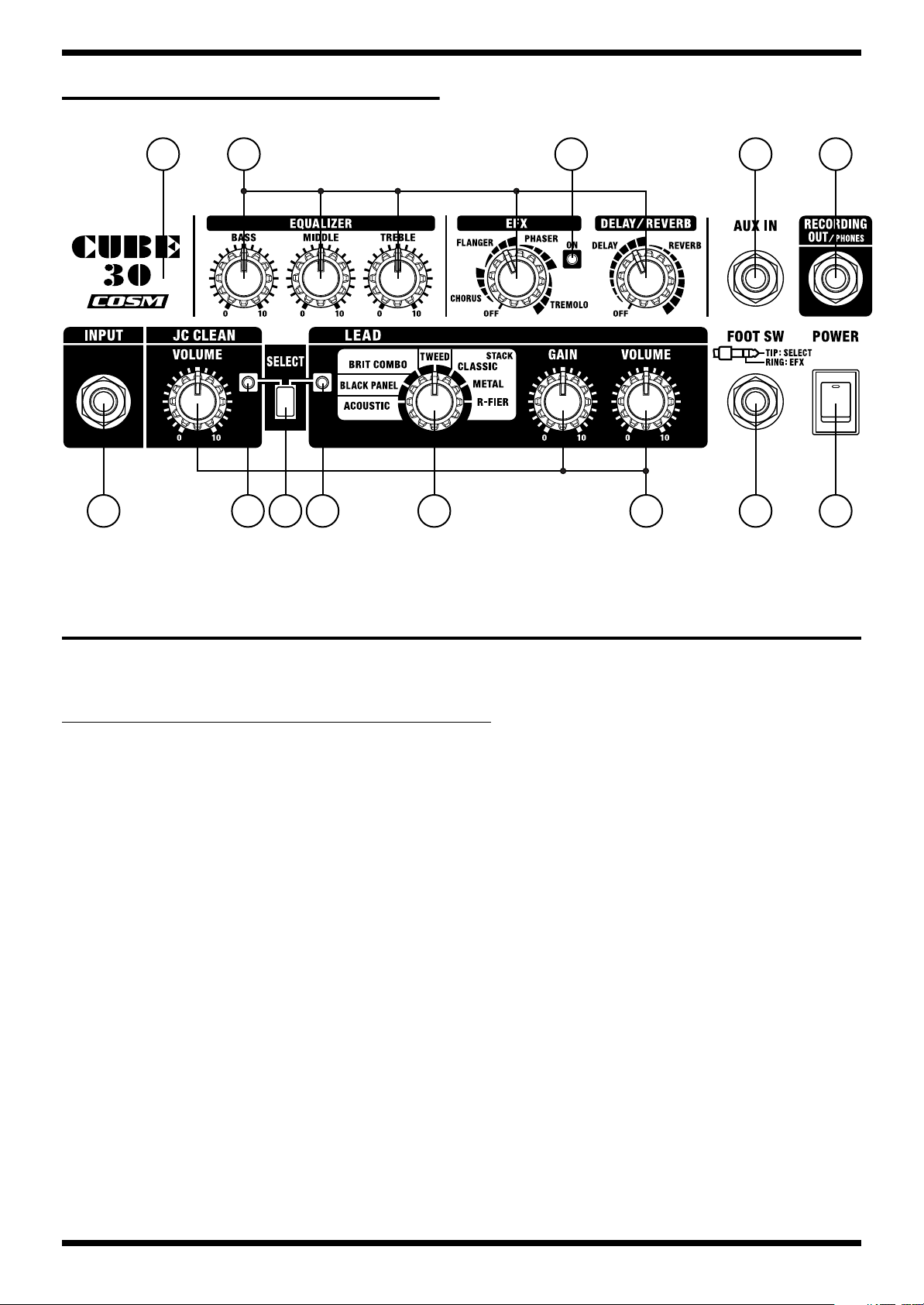
LOCATION OF CONTROLS
fig.panel30
CUBE-30
469
1 2 5 6 7 8
43
10
7
LOCATION OF CONTROLS PARTS LIST
all JACK NUT : SD000042 JACK NUT
all KNOB : SD000043 KNOB
Part Code Part Name Description Q’ty
No.
1 13449146 YKB21-5012 (W/SW) 6.5MM JACK 1
2 SD000044 LED GREEN 1
3 2249752100 PUSH BUTTON BLACK #521 1
3 SD000059 SPUP128100 PUSH SWITCH 1
4 SD000045 LED RED 1
5 SD000061 SRBV17 ROTARY SWITCH 1
6 SD000055 RK09L1120 10KB 9MM ROTARY 8
7 13449252 YKB21-5006 (STEREO W/SW) 6.5MM JACK 1
8 02897801 SDDJE13200 94V-0 SEESAW SWITCH 1
9 SD000030 CHASSIS 1
10 13449145 YKB21-5010 6.5MM JACK 2
3
Page 4
Jul.2002
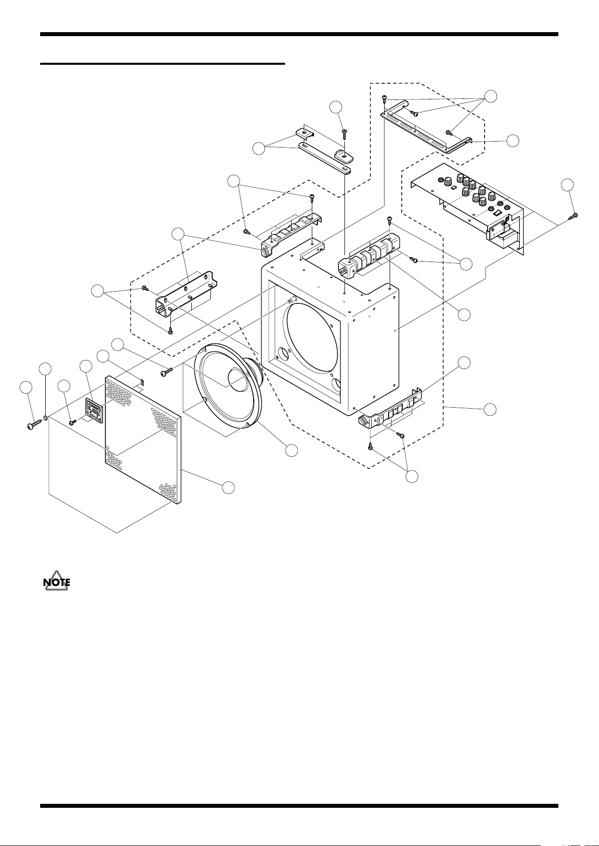
EXPLODED VIEW(CABNET)
fig.explo-1
e
c
3
e
4
e
e
d
b
g
f
1
a
4
4
5
f
6
2
Don’t keep a speaker cable from contact a Heatsink and a primary power
supply unit when equipping with a chassis.
7
e
4
Page 5

EXPLODED VIEW PARTS LIST(CABINET)
[PART]
Part Code Part Name Description Q’ty
No
1 SD000017 BADGE 1
2 SD000034 GRILL 1
3 SD000035 HANDLE WITH ESCUTHEON 1
4 SD000031 CORNER PROTECTOR 4
5 SD000066 TRIM 1
6 SD000028 CABINET ASSY 1
7 SD000033 SPEAKER 364510 1
[SCREW]
No Part Code Part Name Description Q’ty
a SD000047 SCREW 3X8 OVALHEAD MACHINE BZC 2
b 40011689 SPEED NUT M3 F-TYPE 2
c SD000048 SCREW 5X35 OVALHEAD MACHINE BZC 2
d SD000019 SCREW 4X25 BINDING MACHINE BZC 4
e SD000067 SCREW 3X12 TRUSS TAPTITE A1 BZC 29
f SD000068 SCREW 4X25 TRUSS TAPTITE A1 BZC 8
g SD000069 WASHER M4 11FAI ADDITIONAL PLASTIC WASHER 4
CABINET ASSY include the following parts.
SD000031 CORNER PROTECTOR
SD000066 TRIM
CUBE-30
5
Page 6

Jul.2002
EXPLODED VIEW(CHASSIS)
fig.explo-2
10
5
4
b
f
a
2
i
8
n
h
e
i
e
d
7
k
9
f
6
h
o
m
g
n
l
3
c
j
d
11
1
6
Page 7

EXPLODED VIEW PARTS LIST(CHASSIS)
[PART]
No
Part Code Part Name Description Q’ty
1 SD000015 AC CORD SP-502B 240V 1
1 SD000014 AC CORD SP-301 117V 1
1 SD000012 AC CORD SP-023 230V 1
1 SD000016 AC CORD SP-60 230VE 1
2 SD000030 CHASSIS 1
3 72360705 CORD HOOK 2
4 2249752100 PUSH BUTTON BLACK #521 1
5 SD000043 KNOB 9
6 12369410RT AC CORD HOLDER 1702B 2
7 SD000053
8 SD000036 HEATSINK 1
9 SD000001 PCB ASSY 100/117V 1
10 02897801 SEESAW SWITCH SDDJE13200 94V-0 1
11 SD000064 TRANSFORMER ST-11544 230V/240V 1
11 SD000065 TRANSFORMER ST-11545 100V/117V 1
* i SCREW M3X6 is not included in PCB ASSY.
PCB SPACER
*
[SCREW]
No Part Code Part Name Description Q’ty
a 17048631 VR ACCESSORY WASHER M9 9
b 17048630 VR ACCESSORY NUT M9 9
c 40345534 SCREW M4X25 PAN MACHINE W/SW+PW BZC 2
d 40011767 FLANGE HEX NUT M4 FE CM 4
e 40011756 FLANGE HEX NUT M3 ZC 4
f SD000042 JACK NUT 4
g SD000018 SCREW 4X12 BINDING MACHINE BZC 2
h 40011889 EXTERNAL TOOTH WASHER M4 FECM 3
i 40017934 SCREW M3X6 PAN MACHINE W/SW+PW FE ZC 4
j 40010301 SCREW M3X20 BINDING MACHINE BZC 2
k 40012878 SCREW M3X10 PAN MACHINE W/SW+PW ZC 2
l 40012945 SCREW M3X6 PAN MACHINE W/SW+PW BZC 2
m 22150518 STANDOFF HEX.BOSS 5.5X15 M3 2
n SD000052 SCREW 4X8 PAN MACHINE BZC 3
o 40347534 M4 SPRING WASHER BZC 2
SCC-6 94V-0
CUBE-30
3
7
Page 8

Jul.2002
PARTS LIST
fig.part1e
SAFETY PRECAUTIONS:
The parts marked have
safety-related characteristics. Use
only listed parts for replacement.
NOTE: The parts marked # are new. (initial parts)
Safety Precautions
The method of replacing the damaged power supply cord vary with serial numbers.
Please refer to followings.
Up to serial No.ZP90419(100V) and NO. ZQ02579(117V,230V) and ZP91179(240V)
Replace power supply cord and PS-1 BOARD when replacing the damaged power supply cord.
Do not replace only power supply cord due to preventing the damage of the traces of the PS-1 BOARD by heating of the soldering iron.
NOTE: Use only the power supply cord and PS-1 BOARD served by Roland Service Center Japan.
Please order the components to Roland Service Center Japan.
PCB ASSY (P/No.SD000001) includes the PS-1 BOARD.
From serial No.ZP90420(100V) and NO. ZQ02580(117V,230V) and ZP91180(240V)
Please replace only the damaged power supply cord according to “Cautions for the replacement of damaged power supply cord.”
CASING
SD000017 BADGE 1
# SD000034 GRILL 1
SD000035 HANDLE WITH ESCUTHEON 1
# SD000028 CABINET ASSY 1
# SD000066 TRIM 1
CABINET ASSY includes the following parts.
SD000031
CORNER PROTECTOR 4
CONSIDERATION ON PARTS ORDRING
When ordering any parts listed in the parts list, please specify the following items in the order sheet.
Failure to completely fill the above items with correct number and description will result in delayed or even
undelivered replacement.
2.
1.
QTY PART NUMBER DESCRIPTION MODEL NUMBER
Ex. 10 22575241 Sharp Key C-20/50
15 2247017300 Knob (orange) DAC-15D
Q’ty
CHASSIS
22360705 CORD HOOK 2
# SD000030 CHASSIS 1
KNOB,BUTTON
2249752100 PUSH BUTTON BLACK #521 1
SD000043 KNOB 9
SWITCH
02897801 SDDJE13200 94V-0 SEESAW SWITCH SW1 1
# SD000061 SRBV17 ROTARY SWITCH SW3 on RSWB 1
SD000059 SPUP128100 PUSH SWITCH SW2 on CB 1
JACK,EXT TERMINAL
13449252 YKB21-5006 (STEREO W/SW) 6.5MM JACK JK2 on MB 1
13449145 YKB21-5010 6.5MM JACK JK3 on MB, JK4 on CB 2
13449146 YKB21-5012 (W/SW) 6.5MM JACK JK1 on CB 1
SPEAKER,BUZZER
#
SD000033 SPEAKER 364510 1
PWB ASSY
#
SD000001 PCB ASSY 100/117V 1
SD000053 PCB SPACER SCC-6 94V-0 HEATSINK 3
# SD000036 HEATSINK 1
PCB ASSY includes the following parts
******** PS-1 BOARD 1
PCB ASSY 100/117V is exclusively for 100/117V use.
For 230/240V, make the following modifications to this “Low Voltage PWB”.
1.Replace fuse to specific one.
2.Write the mark in the specification voltage(230/240V) table of PCB ASSY. See Table A.
8
Page 9

CUBE-30
PWB ASSY
DIODE
SD000044 LED GREEN D13 on CB 1
SD000045 LED RED D14 on CB, D7 on MB 1
POTENTIOMETER
FUSE,FUSE HOLDER
# SD000008 5ST 500MA/250V FUSE FH1 on PS1B 1
TRANSFORMER
#
# SD000065 ST-11545 100V/117V TRANSFORMER 1
AC CORD ASSY (Installed)
SD000014 SP-301 117V AC CORD 1
SD000015 SP-502B 240V AC CORD 1
SD000016 SP-60 230VE AC CORD 1
Table A
100 / 117V SB 1A 250V
230 / 240V T500mAL 250V 230 / 240V T 500mAL 250V
SD000055 RK09L1120 10KB 9MM ROTARY VR 1,2,3 on CB, V R4,5,6,7,8 on MB 8
➔
SD000064 ST-11544 230V/240V TRANSFORMER 1
SD000012 SP-023 230V AC CORD 1
100 / 117V
SB 1A 250V
SCREWS
40011756 FLANGE HEX NUT M3 ZC AC CORD BUSH, POWER IC 4
SD000067 SCREW 3X12 TRUSS TAPTITE A1 BZC CORNER PROTECTOR 29
SD000068 SCREW 4X25 TRUSS TAPTITE A1 BZC GRILL, CHASSIS 8
40012878 SCREW M3X10
40017934 SCREW M3X6
40012945 SCREW M3X6
40345534 SCREW M4X25
SD000052 SCREW 4X8 PAN MACHINE BZC AC CORD GND,WIRING GND 3
SD000047 SCREW 3X8 OVALHEAD MACHINE BZC BADGE 2
SD000048 SCREW 5X35 OVALHEAD MACHINE BZC HANDLE 2
22150518 STANDOFF HEX.BOSS 5.5X15 M3 PCB 2
40011889
40011767 FLANGE HEX NUT M4 FE CM TRANSFORMER PCB WIRING 4
40011689 SPEED NUT M3 F-TYPE BADGE 2
40010189 SCREW 3X8 BINDING ZC AC CORD BUSH 2
SD000018 SCREW 4X12 BINDING MACHINE BZC TRANSFORMER 2
SD000019 SCREW 4X25 BINDING MACHINE BZC SPEAKER 4
SD000042 JACK NUT JACK 4
17048630 VR ACCESSORY NUT M9 VR, ROTARY SW 9
17048631 VR ACCESSORY WASHER M9 VR, ROTARY SW 9
PACKING
# SD000049 PACKING BAG 1
# SD000050 PACKING CASE 1
SD000051 PACKING INNER 4
SD000069 WASHER M4 11FAI ADDITIONAL PLASTIC WASHER GRILL 4
40347534 M4 SPRING WASHER BZC TRANSFORMER 2
SD000046 MIRAMIT SHEET 1
EXTERNAL TOOTH WASHER M4
PAN MACHINE W/SW+PW ZC
PAN MACHINE W/SW+PW FE ZC
PAN MACHINE W/SW+PW BZC
PAN MACHINE W/SW+PW BZC
FECM AC CORD GND,WIRING GND 3
POWER IC 2
PCB
STAND OFF NUT 2
AC CORD HOOK 2
4
MISCELLANEOUS
SD000058 ADHESIVE SC608LVZ Wring for primary power transformer and
12369410RT AC CORD HOLDER 1702B AC CORD 2
SD000029 CABLE TIE 6
ACCESSORIES (Standard)
#
SD000003 OWNER’S MANUAL JAPANESE
# SD000004 OWNER’S MANUAL ENGLISH
PS1 BOARD.
9
Page 10

Jul.2002
CHECKING THE VERSION NUMBER
Connection of foot switches
Connect two FS-5U foot switches to the [FOOT.SW] terminals with the
PCS-31 foot switch cable. See “How to set the foot switch FS-5U”.
[polarity] setting for FS-5U foot switch
Set the [polarity] switch to the jack side.
Cable of connections for foot switch
The PCS-31 connection cable for the foot switch is a conversion cable
connecting a stereo plug and two standard plugs. Connect the standard
plugs to the foot switches.
The “white” side of the standard plug is used to change JC CLEAN and
LEAD of [SELECT].
The “red side” of the standard plug is used to switch [EFX] on and off.
TIP and RING of the stereo (TRS) plugs of the PCS-31 correspond to
SELECT and EFX, respectively.
Setting up of the panel
Set the LEAD CH rotary switch to “ACOUSTIC”, and all other knobs to
“0” or “off”.
Undepress the [SELECT] button to JC CLEAN (to green LED when the
power is on).
How to check the version number
After completing 1) and 2), turn on the power while pressing the foot
switch for SELECT switching (white side). Then within four seconds,
press it again twice to start the test mode.
As soon as the test mode starts, all LEDs blink several times, then some
LEDs blink to display the version number (see the following on how to
display the version number).
TEST MODE
1 What is needed
• Headphones 1 set
• Foot switch BOSS FS-5U (Optional) 2 units
• Connection cable for foot switch ROLAND PCS-31 (Optional) 1 unit
2 How to enter the test mode
2.
3.
1.
Connection of foot switches
4.
❍
●
5.
1.
2.
3.
Connect two FS-5U foot switches to the [FOOT.SW] terminals with the
PCS-31 foot switch cable (See CHECKING THE VERSION NUMBER
1. Connection of foot switches).
Setting up of the panel
Set the LEAD CH rotary switch to “ACOUSTIC”, and all other knobs to
“0” or “off”.
Undepress the [SELECT] button to JC CLEAN (to green LED when the
power is on).
How to enter the test mode
After completing 1) and 2), turn on the power while pressing the foot
switch for SELECT switching (white side). Then within four seconds,
press it again twice to start the test mode.
As soon as the test mode starts, all LEDs blink several times, then some
LEDs blink to display the version number (see the following on how to
display the version number).
Confirm here that all LEDs can be turned on to show the succeeding
check results correctly.
If setting up of the panel in 2) is not done correctly, the test mode cannot be
started.
If setting up of the panel in 2) is not done correctly, the test mode cannot be
started.
How to display the version number
The version number is displayed by the blinking/off combination of the
green and red LEDs of [SELECT], the red LED of [EFX] ON/OFF.
LEDs used for display 1.00 1.01 1.02 1.03
[JC CLEAN] Green LED
[LEAD] Red LED
[EFX] Red LED
Turn off this unit
❍
●
●
● ● ❍
❍ ● ❍
● ❍ ●
: Blinking
: Off.
. . .
3 How to exit the test mode
Turn off the power to exit the test mode.
4 Skipping
The check mode cannot be skipped.
5 Test items
1) DSP check: (automatically judged)
2) Switch check:
3) Volume check:
10
Page 11

CUBE-30
6 Contents of test items
1. Display the version number
The version number is displayed by the blinking/off combination of the
green and red LEDs of [SELECT], the red LED of [EFX] ON/OFF.
LEDs used for display 1.00 1.01 1.02 1.03
[JC CLEAN] Green LED
[LEAD] Red LED
[EFX] Red LED
2. DSP check: (automatically judged)
Press the foot switch once for SELECT switching (white side) during
version display to turn off the LEDs and start automatic checks.
The LEDs come on in the order of green, red of [SELECT] and red of
[EFX] during the checks.
If all the checks are completed and the results are OK, all LEDs blink.
If the results are NG (no good, fail), only the [EFX] LED blinks.
The automatic checks take approximately 5 - 6 seconds.
If the check results are OK, press the foot switch for SELECT switching
(white side) to proceed to the next check.
If the results are NG, the next check cannot be started.
❍
●
●
● ● ❍
❍ ● ❍
● ❍ ●
: Blinking
: Off.
. . .
Jack switch (foot switch terminal [EFX], [RECORDING OUT/PHONES]
terminal) check
Foot switch terminal [EFX] check
Press the foot switch for EFX (red side) on/off switching to check if the
green LED of [SELECT] comes on.
Then disconnect the PCS-31 plug from the [EFX] terminal to check if the
green LED of [SELECT] goes out and the red LED comes on.
Then insert the PCS-31 plug again to check if the green LED of [SELECT]
comes on.
[RECORDING OUT/PHONES] terminal check
Then insert the headphones plug into the [RECORDING OUT/PHONES]
jack to check if the green LED of [SELECT] goes out and the red LED
comes on.
Finally, disconnect the headphones plug.
If the check results are NG, the next check cannot be started.
If the 2. - 4. checks are completed, both of the green and red LEDs of
[SELECT] blink.
After completing the checks, press the foot switch for SELECT switching
(white side) to proceed to the next check.
❍
●
1.
2.
3.
b.
a.
5. Volume check:
3. Switch check:
When the switch check starts, all LEDs go out.
[SELECT] switch operation check
Press the [SELECT] button.
If the check results are OK, both of the green and red LEDs of [SELECT]
come on.
If the check results are NG, none of the LEDs come on. The next check
cannot be started, either.
Operation check for “AMP TYPE switching” of LEAD rotary switch
Shift the switch slowly in the following order to check if the switch
setting is read correctly.
At this time, check if the green and red LEDs of [SELECT] come on
alternately as follows.
ACOUSTIC (green, red) → BLACK PANEL (green) → BRIT COMBO
(red) → TWEED (green) → CLASSIC STACK (red) → METAL STACK
(green) → R-FIER STACK (red) → METAL STACK (green) → CLASSIC
STACK (red) → TWEED (green) → BRIT COMBO (red) → BLACK
PANEL (green) → ACOUSTIC (red)
If the check results are OK, both of the green and red LEDs of [SELECT]
come on.
If the check results are NG, the green and red LEDs do not come on
simultaneously. The next check cannot be started, either.
If the switch knob is shifted too fast, the green and red LEDs blink.
In this case, repeat the operation slowly to allow the switch settings to be read
at all positions.
When the volume knob is shifted, the DSP starts self-transmission, and
sound is output from the speaker if connected during the check. The sound
volume varies depending on the position of the knob during the volume
setting reading.
When the volume check starts, all LEDs go out.
The following confirmation is done for the volume check.
Readings of the respective volumes are detected at (1) “0” or “OFF”, (2)
center, and (3) “10” or the maximum position. Check the results by
means of the green LED of [SELECT] as follows.
(1) Detection at “0” or “OFF” Green LED of [SELECT] goes out.
(2) Detection at the center Green LED of [SELECT] blinks once.
(3) Detection at “10” or “maximum” Green LED of [SELECT] comes
on.
Turn the volume knob slowly from position (1) to position (3).
Volume reading for check in (3) is completed.
After the volume reading is completed, the green LED of [SELECT]
remains on and waits for the next check.
The checks are done in the following order.
After each volume check is completed, be sure to keep the knob in position (3)
(all the way clockwise). Otherwise, the next volume check cannot be started.
Order of checks
JC CLEAN [VOLUME] → LEAD [GAIN] → LEAD [VOLUME] → [BASS] →
[MIDDLE] → [TREBLE] → [EFX] → [REVERB]
If a check is done in the wrong order, the operation is neglected and only the
volume to be checked is detected.
If one of (1) - (3) cannot be detected at the respective volume levels, the next
check cannot be started.
When all VR checks are completed, all LEDs blink.
If all the check results are OK, the green and red LEDs of [SELECT] blink.
This completes the checking process.
Turn off the power.
11
Page 12

Jul.2002
CAUTIONS FOR THE REPLACEMENT OF DAMAGED POWER SUPPLY CORD
100V ZP90420 117V,230V,230VE ZQ02580 240VA ZP91180 -
Please refer to the follwing “Notes” and confrim the Serial number when you replace the power supply cord.
Notes
The distance between terminal (included the part of winding the wire) is more than 6mm (refer to Fig.1).
fig.30ac1
PS-1 BOARD
COMMON
6mm min
POWER SUPPLY
CORD
117V BLACK WHITE
230V BROWN BLUE
230VE BROWN BLUE
240V BROWN BLUE
1.
2.
3.
WIRING COLOR
HOT COMMON
HOT
Please wind the wire around the terminal 1.5 times before soldering wire to terminal.(refer to Fig.2)
fig.30ac2
When you remove the power supply cord from PS-1 BOARD, the dregs of a wire should not remain on a terminal.
12
 Loading...