

Page 1

VM-C7200/C7100
Owner’s Manual
Notation used in this Owner’s Manual
To make operation procedures easy to understand, the following notation system is
adopted:
• Characters and numbers in square brackets [ ] indicate buttons on the front panel. For
example, [LEVEL METER] represents the LEVEL METER button.
• Notes in the right margin of sections marked include information requiring your
attention. Be sure to read these notes.
• Notes in the right margin of sections marked include information you may find
convenient to know. Read these as necessary.
• indicates that the paragraph marked contains information related to an operation.
• Items marked indicate terms that are useful to know. Read these as necessary.
• If you come across a term in this manual that you don't understand, look it up in the
“Glossary”
(p. 264).
• If the volume decreases, or if the unit does not operate properly, read
“Troubleshooting”
* All product names mentioned in this document are trademarks or registered trademarks of their
respective owners.
Copyright © 1999 ROLAND CORPORATION
All rights reserved. No part of this publication may be reproduced in any form without the
written permission of ROLAND CORPORATION.
(p. 232). For answers to questions about the V-Mixing System, read
(p. 261).
Before using this unit, carefully read the sections entitled: “IMPORTANT SAFETY
INSTRUCTIONS” (Owner’s manual p. 2), “USING THE UNIT SAFELY” (Owner’s
manual p. 3), and “IMPORTANT NOTES” (Owner’s manual p. 4). These sections
provide important information concerning the proper operation of the unit. Additionally,
in order to feel assured that you have gained a good grasp of every feature provided
by your new unit, Owner’s manual should be read in its entirety. The manual should
be saved and kept on hand as a convenient reference.
“Q & A”
Page 2
CAUTION
RISK OF ELECTRIC SHOCK
DO NOT OPEN
ATTENTION: RISQUE DE CHOC ELECTRIQUE NE PAS OUVRIR
CAUTION: TO REDUCE THE RISK OF ELECTRIC SHOCK,
DO NOT REMOVE COVER (OR BACK).
NO USER-SERVICEABLE PARTS INSIDE.
REFER SERVICING TO QUALIFIED SERVICE PERSONNEL.
The lightning flash with arrowhead symbol, within an
equilateral triangle, is intended to alert the user to the
presence of uninsulated “dangerous voltage” within the
product’s enclosure that may be of sufficient magnitude to
constitute a risk of electric shock to persons.
The exclamation point within an equilateral triangle is
intended to alert the user to the presence of important
operating and maintenance (servicing) instructions in the
literature accompanying the product.
INSTRUCTIONS PERTAINING TO A RISK OF FIRE, ELECTRIC SHOCK, OR INJURY TO PERSONS.
IMPORTANT SAFETY INSTRUCTIONS
SAVE THESE INSTRUCTIONS
WARNING - When using electric products, basic precautions should always be followed, including the following:
Read all the instructions before using the product.
1.
Do not use this product near water — for example, near a
2.
bathtub, washbowl, kitchen sink, in a wet basement, or near
a swimming pool, or the like.
This product should be used only with a cart or stand that is
3.
recommended by the manufacturer.
This product, either alone or in combination with an amplifier
4.
and headphones or speakers, may be capable of producing
sound levels that could cause permanent hearing loss. Do
not operate for a long period of time at a high volume level
or at a level that is uncomfortable. If you experience any
hearing loss or ringing in the ears, you should consult an
audiologist.
The product should be located so that its location or position
5.
does not interfere with its proper ventilation.
The product should be located away from heat sources such
6.
as radiators, heat registers, or other products that produce
heat.
The product should be connected to a power supply only of
7.
the type described in the operating instructions or as marked
on the product.
8.
The power-supply cord of the product should be unplugged
from the outlet when left unused for a long period of time.
9.
Care should be taken so that objects do not fall and liquids
are not spilled into the enclosure through openings.
10.
The product should be serviced by qualified service
personnel when:
A.
The power-supply cord or the plug has been damaged; or
B.
Objects have fallen, or liquid has been spilled into the
product; or
C.
The product has been exposed to rain; or
D.
The product does not appear to operate normally or
exhibits a marked change in performance; or
E.
The product has been dropped, or the enclosure
damaged.
11.
Do not attempt to service the product beyond that described
in the user-maintenance instructions. All other servicing
should be referred to qualified service personnel.
For the USA
GROUNDING INSTRUCTIONS
This product must be grounded. If it should malfunction or breakdown, grounding provides a path of least resistance for
electric current to reduce the risk of electric shock.
This product is equipped with a cord having an equipment-grounding conductor and a grounding plug. The plug must be
plugged into an appropriate outlet that is properly installed and grounded in accordance with all local codes and ordinances.
DANGER: Improper connection of the equipment-grounding conductor can result in a risk of electric shock. Check with a
qualified electrician or serviceman if you are in doubt as to whether the product is properly grounded.
Do not modify the plug provided with the product — if it will not fit the outlet, have a proper outlet installed by a qualified
electrician.
For the U.K.
WARNING:
IMPORTANT:
As the colours of the wires in the mains lead of this apparatus may not correspond with the coloured markings identifying
the terminals in your plug, proceed as follows:
The wire which is coloured GREEN-AND-YELLOW must be connected to the terminal in the plug which is marked by the
letter E or by the safety earth symbol or coloured GREEN or GREEN-AND-YELLOW.
The wire which is coloured BLUE must be connected to the terminal which is marked with the letter N or coloured BLACK.
The wire which is coloured BROWN must be connected to the terminal which is marked with the letter L or coloured RED.
The product which is equipped with a THREE WIRE GROUNDING TYPE LINE PLUG must be grounded.
THIS APPARATUS MUST BE EARTHED
THE WIRES IN THIS MAINS LEAD ARE COLOURED IN ACCORDANCE WITH THE FOLLOWING CODE.
GREEN-AND-YELLOW: EARTH, BLUE: NEUTRAL, BROWN: LIVE
Page 3
Used for instructions intended to alert
the user to the risk of death or severe
injury should the unit be used
improperly.
Used for instructions intended to alert
the user to the risk of injury or material
damage should the unit be used
improperly.
* Material damage refers to damage or
other adverse effects caused with
respect to the home and all its
furnishings, as well to domestic
animals or pets.
The symbol alerts the user to important instructions
or warnings.The specific meaning of the symbol is
determined by the design contained within the
triangle. In the case of the symbol at left, it is used for
general cautions, warnings, or alerts to danger.
The symbol alerts the user to items that must never
be carried out (are forbidden). The specific thing that
must not be done is indicated by the design contained
within the circle. In the case of the symbol at left, it
means that the unit must never be disassembled.
The ● symbol alerts the user to things that must be
carried out. The specific thing that must be done is
indicated by the design contained within the circle. In
the case of the symbol at left, it means that the powercord plug must be unplugged from the outlet.
001
• Before using this unit, make sure to read the instructions below, and the Owner’s Manual.
.............................................................................................................
002a
• Do not open or perform any internal modifications
on the unit.
.............................................................................................................
007
• Make sure you always have the unit placed so it is
level and sure to remain stable. Never place it on
stands that could wobble, or on inclined surfaces.
.............................................................................................................
009
• Avoid damaging the power cord. Do not bend it
excessively, step on it, place heavy objects on it, etc.
A damaged cord can easily become a shock or fire
hazard. Never use a power cord after it has been
damaged.
.............................................................................................................
013
• In households with small children, an adult should
provide supervision until the child is capable of
following all the rules essential for the safe
operation of the unit.
.............................................................................................................
014
• Protect the unit from strong impact.
(Do not drop it!)
.............................................................................................................
015
• Do not force the unit’s power-supply cord to share
an outlet with an unreasonable number of other
devices. Be especially careful when using extension
cords—the total power used by all devices you have
connected to the extension cord’s outlet must never
exceed the power rating (watts/amperes) for the
extension cord. Excessive loads can cause the
insulation on the cord to heat up and eventually
melt through.
.............................................................................................................
016
• Before using the unit in a foreign country, consult
with your retailer, the nearest Roland Service
Center, or an authorized Roland distributor, as
listed on the “Information” page.
.............................................................................................................
020
• Keep lithium batteries out of reach of small
children. If a child has accidentally swallowed a
battery, see a doctor immediately.
.............................................................................................................
021
• Lithium batteries must never be recharged, heated,
taken apart, or thrown into a fire or water.
102b
• Always grasp only the plug on the power-supply
cord when plugging into, or unplugging from, an
outlet or this unit.
............................................................................................................
104
• Try to prevent cords and cables from becoming
entangled. Also, all cords and cables should be
placed so they are out of the reach of children.
............................................................................................................
106
• Never climb on top of, nor place heavy objects on
the unit.
............................................................................................................
107b
• Never handle the power cord or its plugs with wet
hands when plugging into, or unplugging from, an
outlet or this unit.
............................................................................................................
108a
• Before moving the unit, disconnect the power plug
from the outlet, and pull out all cords from external
devices.
............................................................................................................
109a
• Before cleaning the unit, turn off the power and
unplug the power cord from the outlet (p. 24).
............................................................................................................
110a
• Whenever you suspect the possibility of lightning in
your area, pull the plug on the power cord out of
the outlet.
............................................................................................................
113
• Use only the specified type (model no. CR-2032) of
lithium battery (p. 26). Be sure to insert it as directed
(to ensure correct polarity).
............................................................................................................
114
• Used lithium batteries must be disposed of in
compliance with whatever regulations for their safe
disposal that may be observed in the region in
which you live.
............................................................................................................
3
Page 4
Important Notes
In addition to the items listed under “IMPORTANT SAFETY INSTRUCTIONS” and “USING THE UNIT SAFELY” on pages 2
and 3, please read and observe the following:
Power supply
• Do not use this unit on the same power circuit with any
device that will generate line noise (such as an electric
motor or variable lighting system).
• Before connecting this unit to other devices, turn off the
power to all units. This will help prevent malfunctions
and/or damage to speakers or other devices.
Placement
• Using the unit near power amplifiers (or other equipment
containing large power transformers) may induce hum. To
alleviate the problem, change the orientation of this unit; or
move it farther away from the source of interference.
• This device may interfere with radio and television
reception. Do not use this device in the vicinity of such
receivers.
• To avoid possible breakdown, do not use the unit in a wet
area, such as an area exposed to rain or other moisture.
Maintenance
• For everyday cleaning wipe the unit with a soft, dry cloth
or one that has been slightly dampened with water. To
remove stubborn dirt, use a cloth impregnated with a mild,
non-abrasive detergent. Afterwards, be sure to wipe the
unit thoroughly with a soft, dry cloth.
• Never use benzine, thinners, alcohol or solvents of any
kind, to avoid the possibility of discoloration and/or
deformation.
Repairs and data
• Please be aware that all data contained in the unit’s
memory may be lost when the unit is sent for repairs.
Important data should always be backed up on a memory
card, or written down on paper (when possible). During
repairs, due care is taken to avoid the loss of data.
However, in certain cases (such as when circuitry related
to memory itself is out of order), we regret that it may not
be possible to restore the data, and Roland assumes no
liability concerning such loss of data.
Memory backup
• This unit contains a battery which powers the unit’s
memory circuits while the main power is off. When this
battery becomes weak, the message shown below will
appear in the display. Once you see this message, have the
battery replaced with a fresh one as soon as possible to
avoid the loss of all data in memory. To have the battery
replaced, consult with your retailer, the nearest Roland
Service Center, or an authorized Roland distributor, as
listed on the “Information” page.
“Checking BATTERY ... NG.”
• Unfortunately, it may be impossible to restore the contents
of data that was stored on a memory card once it has been
lost. Roland Corporation assumes no liability concerning
such loss of data.
• Use a reasonable amount of care when using the unit’s
buttons, sliders, or other controls; and when using its jacks
and connectors. Rough handling can lead to malfunctions.
• Never strike or apply strong pressure to the display.
• When connecting / disconnecting all cables, grasp the
connector itself—never pull on the cable. This way you
will avoid causing shorts, or damage to the cable’s internal
elements.
• A small amount of heat will radiate from the unit during
normal operation.
• To avoid disturbing your neighbors, try to keep the unit’s
volume at reasonable levels. You may prefer to use
headphones, so you do not need to be concerned about
those around you (especially when it is late at night).
• When you need to transport the unit, package it in the box
(including padding) that it came in, if possible. Otherwise,
you will need to use equivalent packaging materials.
• Use a cable from Roland to make the connection. If using
some other make of connection cable, please note the
following precautions.
•
Some connection cables contain resistors. Do not use cables
that incorporate resistors for connecting to this unit. The
use of such cables can cause the sound level to be
extremely low, or impossible to hear. For information on
cable specifications, contact the manufacturer of the cable.
• The explanations in this manual include illustrations that
depict what should typically be shown by the display.
Note, however, that your unit may incorporate a newer,
enhanced version of the system (e.g., includes newer
sounds), so what you actually see in the display may not
always match what appears in the manual.
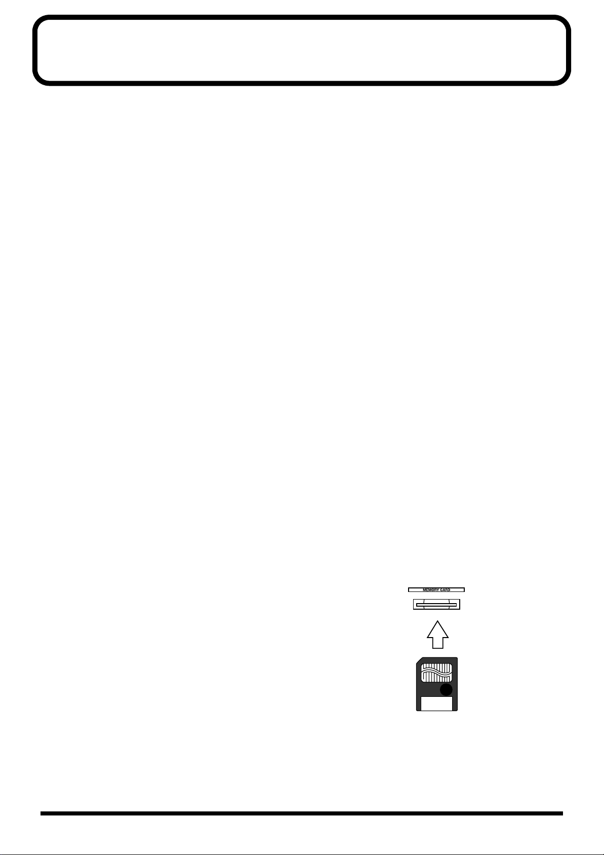
Before using cards
Using memory cards
• Carefully insert the memory card all the way in—until it is
firmly in place.
Additional precautions
• Please be aware that the contents of memory can be
irretrievably lost as a result of a malfunction, or the
improper operation of the unit. To protect yourself against
the risk of loosing important data, we recommend that you
periodically save a backup copy of important data you
have stored in the unit’s memory on a memory card.
4
• Never touch the terminals of the memory card. Also, avoid
getting the terminals dirty.
Page 5

Table of Contents
Chapter 1 Introduction .........................................................................10
Main Features............................................................................................................................................ 10
Names of Things and What They Do.................................................................................................... 11
A: Display area ..............................................................................................................................12
B: Monitor area.............................................................................................................................. 13
C: Memory/Recall area................................................................................................................15
D: Transport area .......................................................................................................................... 16
E: Fader parameter/Section select area .....................................................................................17
F: Channel fader (button) area ....................................................................................................19
Rear panel....................................................................................................................................... 20
Before Operation.......................................................................................................................................21
Connections....................................................................................................................................21
Turning the power on/off ........................................................................................................... 24
Adjusting the display’s contrast ................................................................................................. 25
Adjusting internal clock............................................................................................................... 25
If you get lost .................................................................................................................................28
Preparing a memory card ............................................................................................................28
Internal Signal Flow................................................................................................................................. 29
About Digital Connections and the Master Clock...............................................................................31
Digital sound device and master clock...................................................................................... 31
DIGITAL A and B terminals and reception of word clocks....................................................32
Word clock connector...................................................................................................................32
Checking the overall system........................................................................................................ 32
Restoring the Original Factory Settings (Factory Reset).....................................................................33
Factory reset procedure................................................................................................................ 33
Table of Contents
Chapter 2 Basic Operations and Their Settings
(System/Project)....................................................................................34
Basic Operations....................................................................................................................................... 34
Screen descriptions .......................................................................................................................34
Setting parameters ........................................................................................................................35
Level Meter Settings................................................................................................................................. 36
Settings for the Panel (Knobs and Display)..........................................................................................37
Connection Setting of Processor and Console...................................................................................... 39
Checking the overall system........................................................................................................ 39
When using two consoles ............................................................................................................ 40
Settings related to cascade connection.......................................................................................41
Chapter 3 Data Storage and Retrieval.................................................43
Copying Libraries Containing Various Settings..................................................................................44
Calling up and saving a library screen ...................................................................................... 44
Storing a Mixing State (Scene)................................................................................................................47
Storing/recalling/erasing a scene..............................................................................................47
Selecting which parameters will be recalled.............................................................................48
Storing and Recalling All Mixer Settings (Project)..............................................................................50
Preparing a memory card for project storage........................................................................... 51
Storing a project............................................................................................................................. 52
Re-naming/erase-protecting a project.......................................................................................53
Selecting a project.......................................................................................................................... 54
Copying a project.......................................................................................................................... 55
Erasing a project from a memory card....................................................................................... 55
Copying Data to/from a Memory Card................................................................................................56
Moving and returning a set of libraries in a console to and from a memory card..............56
Backing up a memory card..........................................................................................................57
5
Page 6

Table of Contents
Chapter 4 Useful Functions .................................................................58
Storing Frequently Used Screens (Macro Function)............................................................................58
Storing a screen as a macro.......................................................................................................... 58
Recalling a screen (macro) ...........................................................................................................58
Clearing a stored macro...............................................................................................................58
Calling Up Stored Connections (EZ Routing)......................................................................................59
Routing template...........................................................................................................................59
Virtual patchbay............................................................................................................................60
Directly Calling Up a Screen for Each Channel (Quick Channel Edit).............................................62
Directly jumping to a parameter’s screen (Quick channel edit)............................................. 63
Simultaneously Setting Several Channels’ Parameters (Parameter View on Fader)......................64
Chapter 5 Mixing Procedure 1 (Input Channel)..................................67
Basic Settings by Input Channel............................................................................................................. 67
Selecting an input channel’s signal source................................................................................67
Gain, Phantom Power Supply, Phase and Attenuator ............................................................68
Correcting a signal’s time delay (PHASE DELAY)..................................................................69
Setting up ON/OFF, SEND LEVEL and PAN for a Channel............................................................ 70
SEND LEVEL and PAN to the main mix and the cue bus......................................................70
Setting a channel’s send level and send point to Flex Buses ..................................................72
PAN and DEPTH for using SURROUND................................................................................. 73
Setting up direct-output channels .............................................................................................. 75
Switching the Status of a Channel ......................................................................................................... 77
Muting a channel (MUTE)........................................................................................................... 77
Listen to a channel by itself (SOLO)...........................................................................................78
Adjusting Various Channel Settings (Equalizer, etc.).........................................................................78
Adjusting frequency characteristics (channel equalizer) ........................................................78
Cutting unwanted low frequencies (HIGH PASS FILTER)....................................................81
Adding an delay-based echo (Feedback Delay) .......................................................................81
Naming input channels................................................................................................................83
Chapter 6 Mixing Procedure 2 (Output and Monitor) ........................84
Setting Master Mix Levels and Stereo Balance.....................................................................................84
Setting the master levels for the MAIN OUTs and cue bus....................................................84
Reducing signal distortion (attenuator).....................................................................................85
A Flex Bus and Its Output.......................................................................................................................86
Outputting signals directly from a Flex Bus .............................................................................86
Sending Flex Bus signals to internal destinations.................................................................... 87
Naming a Flex Bus channel .........................................................................................................89
Routing a Flex Bus to a surround system output.....................................................................89
Surround Output......................................................................................................................................91
Enabling the surround function and selecting the desired mode.......................................... 91
Routing Signals to MULTI OUTs and ASSIGNABLE OUT Jacks.....................................................93
Selecting an output’s signal source ............................................................................................ 93
Naming each output channel......................................................................................................94
Setting an output’s level............................................................................................................... 94
Digital connection output processing (dithering).................................................................... 94
Setting Up Monitor Sends For Studio Or Stage (STUDIO 1 or 2)......................................................95
Setting Up a Monitor For the Mixing Engineer ................................................................................... 96
Turning the monitor send to each output jack on or off ......................................................... 97
Calling up stored level and monitor output presets................................................................97
Specifying a signal to monitor (source select)........................................................................... 98
Setting the monitor volume (line, headphones, digital).......................................................... 98
To instantaneously lower the monitoring volume (DIM).......................................................99
Setting the monitor stereo balance ............................................................................................. 99
Monitoring in mono...................................................................................................................... 99
Talkback and Slate to Player.................................................................................................................100
6
Page 7

Table of Contents
Selecting a talkback/slate microphone....................................................................................100
Turning talkback/slate on and adjusting its volume ............................................................100
Turning the talkback and slate features on and off independently..................................... 101
Chapter 7 Mixing Procedure 3
(Settings Common to Input and Output) ..........................................102
Simultaneously Controlling the Signals of Multiple Channels (Link and Group)....................... 102
Pairing one channel with another (stereo linking).................................................................102
Muting several channels (mute group).................................................................................... 103
Simultaneously changing multiple channels’ levels (fader-group master)........................ 104
Mute- and Solo-Related Settings..........................................................................................................107
Solo volume and setting the channel signal-flow location to be soloed.............................107
Linking stereo-link-to destination ............................................................................................108
Chapter 8 Using the Internal Effects.................................................109
How the Internal Effects Are Organized ............................................................................................ 109
Using the Speaker Modeling function ..................................................................................... 109
Operation for Producing an Effect.......................................................................................................110
Determining the effect position.................................................................................................110
Setting input/output levels....................................................................................................... 113
Selecting the effect library.......................................................................................................... 113
Editing Effects......................................................................................................................................... 115
Determining the Algorithm.......................................................................................................115
Editing effects ..............................................................................................................................115
Saving an Effect State (Effect Library).................................................................................................117
Naming effects libraries .............................................................................................................118
Algorithm List......................................................................................................................................... 119
Table of Contents
Chapter 9 Using the Spectrum Analyzer ..........................................184
Basic Configuration and Operation..................................................................................................... 184
Specifying an effect to used by the analyzer...........................................................................185
Selecting a signal to analyze......................................................................................................185
Changing the analyzer display format (peak-hold, etc.)....................................................... 185
Using a test signal (generator/oscillator)................................................................................186
Specifying the bus to which reference signals are sent ......................................................... 187
Checking the Frequency Characteristics of a Hall or a Signal.........................................................187
Checking the frequency characteristics of a signal ................................................................ 187
Measuring and correcting the characteristics of an acoustic space ..................................... 187
Measuring outputs using the talkback microphone.............................................................. 189
Chapter 10 Combining Recorders.....................................................190
Remotely Controlling a Recorder.........................................................................................................190
Preparations for remote control (MMC settings) ...................................................................191
Playing or stopping recorders...................................................................................................191
Changing track status (Audio status).......................................................................................192
Registering/canceling points in a song (Locate).................................................................... 192
Naming a locate point ................................................................................................................193
Editing a locate point and pre-rolling......................................................................................193
Specifying a point by direct entry of time...............................................................................194
Loop and auto punch in/out..................................................................................................... 195
7
Page 8

Table of Contents
Chapter 11 Recording/Playing Back Fader or Knob Actions
(Automix) .............................................................................................196
Setup for Synchronized Operation with Recorder............................................................................ 196
Selecting the outgoing MIDI sync signals ...............................................................................196
MIDI clock and tempo, metronome .........................................................................................196
Recording Mixing Operations as the Song Develops (Automix Function) ................................... 197
What is the automix function? ..................................................................................................197
Settings (data types) that can be recorded/played back.......................................................198
Setting up the automix function (SET UP) ..............................................................................200
Automix and channel statuses..................................................................................................201
Recording Auto-mixing.........................................................................................................................203
Clearing the memory (CLEAR)................................................................................................. 203
Recording auto-mixing for the first time/recording by overwriting
(ABSOLUTE REC)....................................................................................................................... 204
Recording to modify (RELATIVE REC)...................................................................................205
Re-recording the specified section (PUNCH IN) ................................................................... 206
Playing Back Auto-mixing.................................................................................................................... 207
Editing Auto-mixing.............................................................................................................................. 208
Confirming data (VIEW)............................................................................................................208
Changing data one by one (MICRO EDIT) ............................................................................. 211
Defining the region subject to editing......................................................................................211
Copying (COPY)..........................................................................................................................212
Moving (MOVE).......................................................................................................................... 214
Erasing a section no longer needed (ERASE)..........................................................................216
Erasing an unneeded portion—bringing forward what follows (CUT) .............................217
Gradually shifting values in a specified region (GRADATION).........................................218
Add dynamics (EXPAND)......................................................................................................... 220
Chapter 12 Using with MIDI Devices.................................................222
Settings Related to MIDI ....................................................................................................................... 222
Settings for MIDI transmission/reception and Level Meter Bridge (MB-24) ....................222
Settings related to tempo/metronome.....................................................................................223
Settings related to synchronization.......................................................................................... 224
Receiving or transmitting level/pan using fader or knobs .................................................. 225
Example of Connections........................................................................................................................225
To synchronize with an external MIDI device (the console is used as a slave)................. 225
To make an external MIDI device synchronize with the console
(when the console is used as the master)................................................................................. 226
Controlling a MIDI device from the console........................................................................... 228
Controlling the console from a MIDI device........................................................................... 230
Glossary...............................................................................................232
Parameter List.....................................................................................248
Troubleshooting..................................................................................261
Overall operations....................................................................................................................... 261
The internal effects......................................................................................................................262
MIDI-related problems............................................................................................................... 262
Others............................................................................................................................................ 263
8
Page 9

Table of Contents
Q & A....................................................................................................264
Basic setup and structure........................................................................................................... 264
Hardware ..................................................................................................................................... 266
Effects............................................................................................................................................267
Connecting with other devices.................................................................................................. 268
Other matters...............................................................................................................................269
MIDI Implementation...........................................................................270
Specifications......................................................................................302
VM-C7200: 94 ch V-MIXING CONSOLE............................................................................................302
VM-C7100: 94 ch V-MIXING CONSOLE............................................................................................303
Index.....................................................................................................304
Table of Contents
9
Page 10

Chapter 1 Introduction
Main Features
This multi-function, high-quality all-digital audio mixing system features the
followings:
• All-digital mixing of up to 94 input channels (*).
* When two VM-7200 systems are cascaded together using a VM-24C
Cascade Kit.
• Component design with an independent mixing control surface and mixing
processor. These components are connected using two AES/EBU digital
audio cables, eliminating the need to run an expensive, heavy-duty multichannel, audio cable from a studio or stage to a mixer. The digital cabling
helps preserve the quality of audio signals that might otherwise degrade
over distance.
• The VM consoles are equipped with silent motorized faders.
• Many parameters, including analog input gain, can be controlled or recalled.
• Equipped with multi-purpose Flex buses and a virtual patchbay that enables
user-configurable connections between channels, inputs and outputs.
• Up to eight internal stereo multi-effects processors, plus a stereo insert effect
on the main mix outputs.
• Multiple effect algorithms include a speaker modeling function that
emulates an assortment of popular studio and consumer speakers. Also
included is a microphone simulator that allows signals to sound as if they’ve
been sourced using a variety of popular and classic studio microphones.
• 5.1 Surround mixing capability.
• EZ Routing allows users to quickly recall one of many pre-defined mixer
setting templates. Each EZ Routing template can invoke settings for a
particular situation—recording, live PA, etc. —or musical genre.
• Built-in spectrum analyzer for measuring the frequency characteristics of
input signals, including those produced by users’ monitors. By combining
the system with the built-in noise generator or oscillator, the characteristics
of a monitoring or stage speaker system can be tuned for use in a control
room or performance space.
• By combining separately-sold VM-24E and DIF-AT, up to six multi-track
tape recorders (48 channels) can be digitally connected to this system as a
whole(*).
* Both ADAT and TASCAM TDIF formats are available.
• Equipped with an assortment of powerful features such as Scene memory,
auto-mixing, 24 fader groups, dual channel delays, 4 bands of parametric
equalization per channel and per-channel high-pass filtering.
10
Page 11
Chapter 1 Introduction
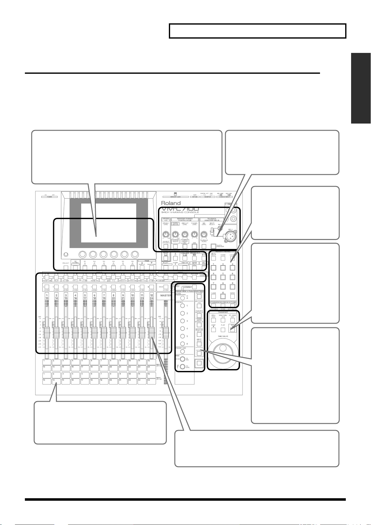
Names of Things and What They Do
The front panel consists of the following areas:
* To learn about items on the mixing processor (VM-7200/7100), refer to “Names
and Functions of Each Part” in the operation manual attached to the processor.
fig.01-1e
A. Display area (p. 12) B. Monitor area (p. 13)
This area contains buttons and knobs that are used to adjust the content
shown in the display. It contains buttons to access the system screen
where overall settings are made and to access the EZ routing function.
Other buttons access the spectrum analyzer, speaker modeling, and
effect functions.
B
In this area you can make monitor-related
settings and adjustments for the person
who is operating the console, or for the
performers in the studio or on stage.
C. Memory recall area
(p. 15)
This area contains the buttons
that are used to numerically
store and recall scenes, mute
groups, or locate points etc.
Chapter 1 Introduction
A
F
You may find it convenient to affix a strip of clear
tape (that can be easily peeled off later) to this
area, and use a felt-tipped marker to make a note
of the input sources (instruments or connected
devices) handled by each channel.
D. Transport area (p. 16)
When a digital multitrack
recorder is connected, these
buttons are used to remotely
C
E
D
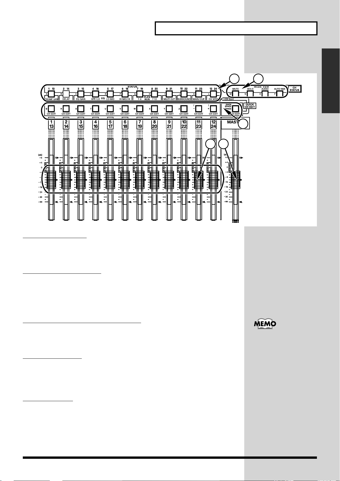
F. Channel fader area (p. 19)
This area consists of the faders for each channel that adjust
the input level etc., and buttons for each channel (status
button / channel edit button).
control the recorder. These
buttons are also used to record
and playback auto-mix data.
Here also are buttons that let
you undo/redo operations and
copy data.
E. Fader parameter/
section select area
(p. 17)
In this area you can specify the
parameter that will be modified
by each fader, or select the
object (section) that will be
edited by panel operations.
This area also contains the
[SHIFT] button that temporarily
changes the function of the
other buttons.
11
Page 12
Chapter 1 Introduction
■
A: Display area
fig.01-2
2
1
3
12
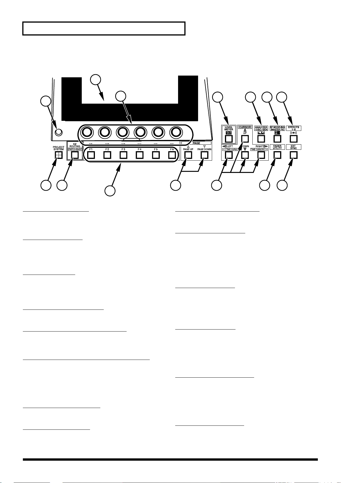
1...
CONTRAST knob
Sets the density (brightness) of the display. Turn the knob to
optimize the display’s visibility for your viewing angle.
2...
DISPLAY (LCD)
Shows a level-meter screen after system is turned on.
Contents of the display change to reflect the current mixing
operation.
V1–V6 knobs
3...
The V1–V6 knobs set/Adjuxt the values of the currently
selected parameters. The function of each knob depends on
the currently displayed screen.
LEVEL METER button
4...
Press this button to display the level meter for each channel.
4 6 7
5
8910111314
9...
FADER UTILITY button
Calls up a screen for linking pairs of channel faders in stereo.
CURSOR buttons
10...
Use these buttons to move the cursor up, down, left or right
on the screen to select a parameter—the currently selected
parameters are outlined on the display. The [LEFT] or
[RIGHT] button changes to a TIME CURSOR button when
[SHIFT] is pressed, allowing you to select the time field to
be altered using the TIME/VALUE dial.
11...
PAGE buttons
Press these buttons while the page list is visible in the upper
right area of the display to change pages. Press [PAGE
DOWN] to go to the next page or [PAGE UP] to return to the
previous page.
ANALYZER/OSC/GEN button
5...
Calls up a screen for setting the attributes of the spectrum
analyzer and its attached oscillator and noise generator.
SP MODELING (MASTER FX) button
6...
Calls up a screen for setting the master effect, the insert
effect dedicated to the stereo signal fed to the MAIN OUT
and MONITOR OUT. In addition to speaker modeling, a 10band parametric equalizer or 3-band dynamics processor is
also available.
EFFECTS 1–8 button
7...
Calls up the main effects screen.
8...
EXT SYNC button
Press this button to synchronize the Automix function to an
external time code source.
12
F1–F6 buttons
12...
Each of these six buttons is associated with a displayed
parameter, and is used for the adjustment of the parameter’s
value. The purpose of each button depends on the parameters
presented in the currently displayed screen. Indicators of
these buttons which are assigned any functions will light.
EZ ROUTING button
13...
Calls up an EZ Routing screen menu that allows you to
select or save signal routing templates. When this button is
pressed in conjunction with [SHIFT], the PATCHBAY
screen appears—this screen allows you to view and change
connections between input and output jacks and channels.
PROJECT button
14...
Calls up a screen menu for saving, selecting or newly
creating a project that stores all current mixer settings. Press
this button together with [SHIFT] to call up a screen menu
of system-wide parameters (SYSTEM menu).
Page 13
Chapter 1 Introduction
■
B: Monitor area
fig.01-3
1
32
4
65
7
15 14 13 12 11
Chapter 1 Introduction
8
9
10
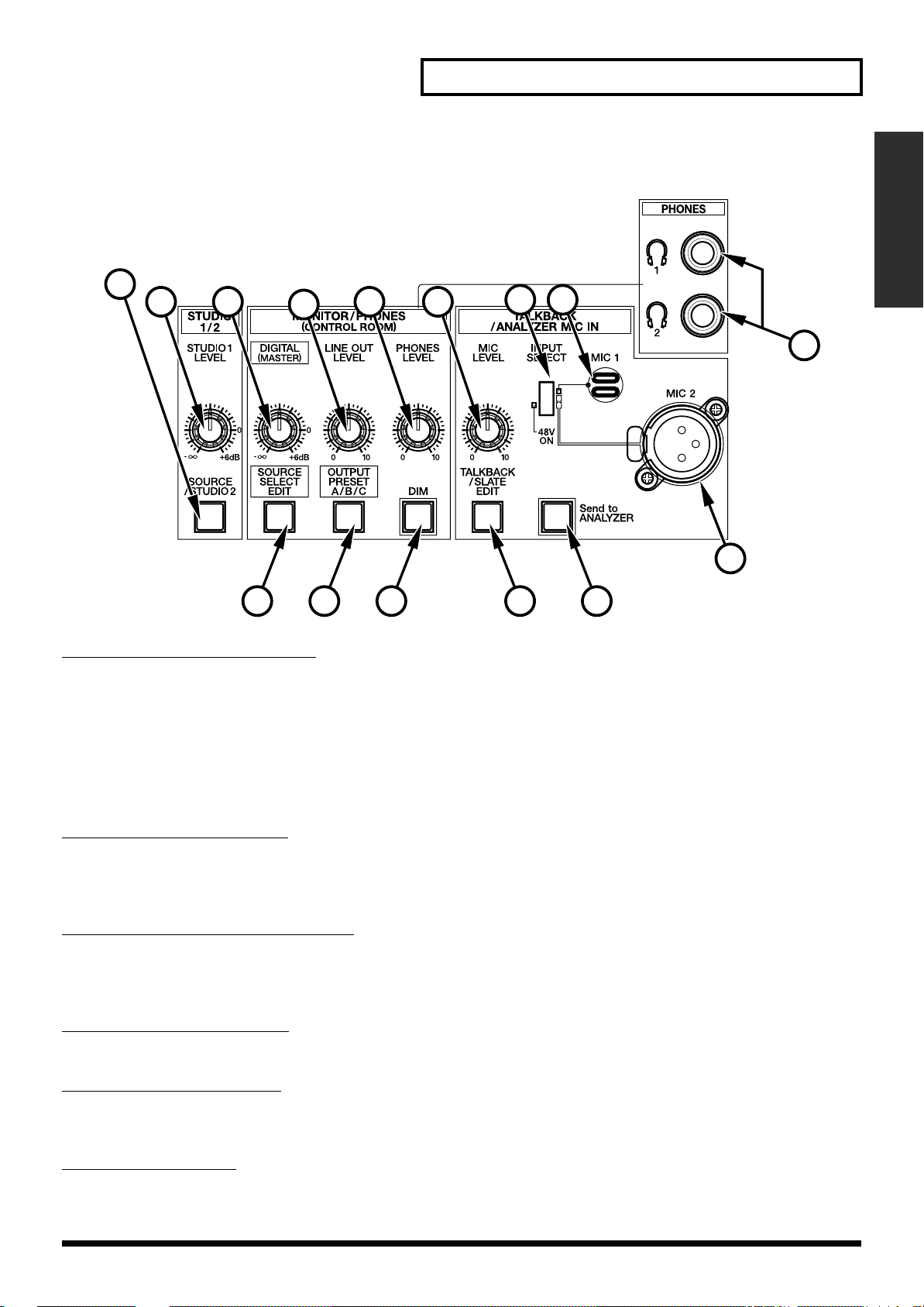
1...SOURCE/STUDIO2 button
Calls up a screen for selecting the source of the STUDIO 1/2 output that typically
feeds studio or stage monitors. Since no knob is provided for STUDIO 2, its level is
also adjusted from the screen.
* The STUDIO 1 and 2 outputs are monitor signals intended for performers in a
studio or on a stage. The STUDIO 1 signals are output in stereo to
ASSIGNABLE OUTs 1 and 2 of the mixing processor, while STUDIO 2’s stereo
signal is sent to ASSIGNABLE OUTs 3 and 4.
2...
STUDIO 1 LEVEL knob
Adjusts the level of the STUDIO 1 outputs. (Since the same setting can be changed
using a V knob when the source select screen of STUDIO 1 is displayed, the physical
position of this knob may differ from the actual STUDIO 1 setting.)
DIGITAL (MASTER) level knob
3...
Master knob for changing the level of signals to be sent to the CONTROL ROOM
monitor output of the console. When this knob is moved, the volume of audio
transmitted via the DIGITAL OUT is also changed.
4...LINE OUT LEVEL knob
Level knob (analog volume) for the LINE OUT jacks on the rear of the console.
5...
PHONES LEVEL knob
Volume knob for headphones connected to the PHONES 1 and/or 2 jacks. The
volume of the two headphone jacks cannot be adjusted independently.
MIC LEVEL knob
6...
Knob for adjusting the level of the talkback system. The knob also functions as a gain
control for any connected talkback microphone.
13
Page 14

Chapter 1 Introduction
b
7...
INPUT SELECT switch
Selects the microphone input to be used for talkback. According to the position of the
switch, the microphone built into the panel (MIC 1) or an external microphone (MIC
2) can be selected. Set the switch to “48V ON” only when phantom power is required
for an external talkback microphone.
MIC 1 (internal microphone)
8...
Small microphone built into the panel used for talkback communication with
performers.
9...
PHONES (headphone jacks)
Two jacks for connecting stereo headphones. The two jacks share a common stereo
signal.
10...
MIC 2 (external microphone connector)
Connector for an external microphone to be used for talkback. You can purchase a
commercially available flexible gooseneck microphone holder for this microphone.
Send to ANALYZER button
11...
Press this button to send the talkback microphone signal to the internal spectrum
analyzer. When the button is pressed, [ANALYZER/OSC/GEN] also lights and the
display changes to the analyzer screen.
This feature presumes that an external talkback microphone uses Channel 24. The
built-in talkback microphone’s signal will automatically be routed to the analyzer
via channel 24.
12...
TALKBACK/SLATE button
Activates or de-activates the talkback function, according to the setting of the
TALKBACK BUTTON system parameter. This parameter can be set to
MOMENTARY—talkback is on only while [TALKBACK/SLATE] is depressed—or
to LATCH, where talkback is switched on with one [TALKBACK/SLATE] buttonpress, and off with another. When talkback is activated, audio from the designated
talkback microphone is injected into the selected bus.
DIM button
13...
Dim on/off button lowers the monitor volume to a pre-defined level.
14...
OUTPUT PRESET A/B/C button
Selects any of three user-definable CONTROL ROOM monitor setups—each setup
contains a collection of CONTROL ROOM monitor parameter settings. Every press
of the A/B/C button toggles between setups A and B—to select Setup C, press the
SHIFT button and the A/B/C button.
15...
(CONTROL ROOM) SOURCE SELECT button
Calls up a screen from which you can select the source of the signal to be fed to the
CONTROL ROOM monitor output.
Press this button together with [SHIFT] to display the detailed setting screen
associated with the three CONTROL ROOM monitor setups described in “14”
above.
While [TALKBACK/
SLATE] is turned on,
Channel 24 is presumed to
e controlling an external
talkback microphone and is
thus unavailable for other
purposes. This does not,
however, reset the source
setting for Channel 24
shown on the PATCHBAY
screen (p. 60).
14
Page 15
Chapter 1 Introduction
■
C: Memory/Recall area
fig.01-4
1
2
3
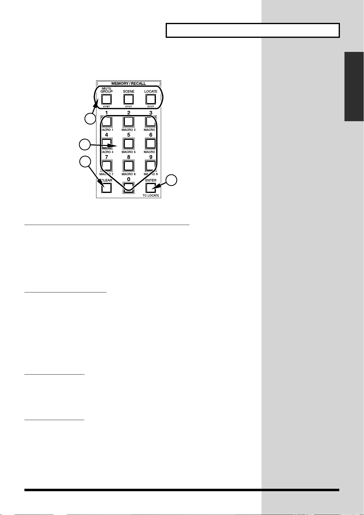
MUTE GROUP, SCENE and LOCATE buttons
1...
Press MUTE GROUP, SCENE or LOCATE to set the operating mode of the ten-key
numeric keypad. One of the three buttons is typically lit to indicate the keypad’s
current operating mode—this may not be the case, however, during certain
operations, such as character entry. Depending on which of the three buttons is
active, you can use the keypad to control mute groups, or save and recall Scenes or
Locate points. Press any of the three buttons together with [SHIFT] to call up the
corresponding detailed setting screen.
Chapter 1 Introduction
4
0–9 (ten-key keypad)
2...
When [MUTE GROUP] is active, the numeric keypad buttons function as master
mute buttons for the corresponding mute groups. When [SCENE] or [LOCATE] is
active, use these buttons to specify a Scene or Locate point to be stored or recalled.
While [SHIFT] is pressed, the keypad buttons function as macro buttons. The
currently displayed screen, including the current position of the cursor, can be
stored as a numbered macro by pressing any unlit keypad button. Hold [SHIFT] and
press any stored macro’s lit numeric keypad button to jump instantly back to the
screen it invokes.
When entering characters, you can enter numeric values using the keypad buttons.
3...
CLEAR button
Clears a stored Scene or Locate point. After pressing Scene or Locate, press [CLEAR]
and then enter the desired number on the ten-key keypad to clear the stored item. To
clear a macro, hold down [SHIFT] and [CLEAR] and enter the macro’s number on
the keypad.
ENTER button
4...
Press this button together with [SHIFT] to call up the Time Code Locate (TC
LOCATE) screen. When this screen is displayed, select a locate point using the tenkey numeric keypad and press [ENTER] to move to the location.
15
Page 16
Chapter 1 Introduction
■
D: Transport area
fig.01-5
1 2
5
4
7
8
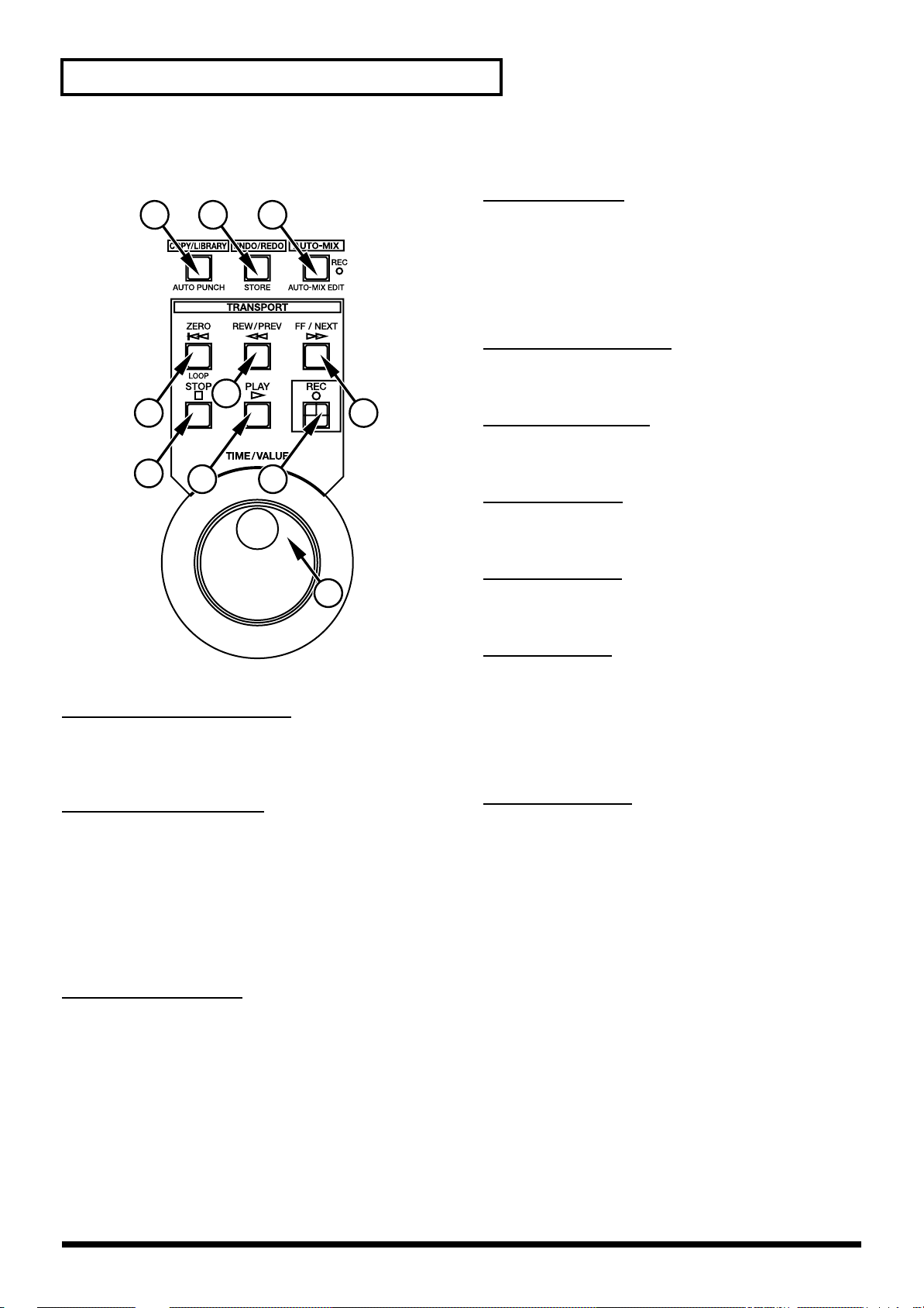
4...
ZERO button
3
6
Sets the current system time to zero (00:00:00:00).
While [SHIFT] is pressed, this button functions as a LOOP
button that turns loop play on and off. When loop play is
turned on, a connected remote device—such as a multitrack recorder—will repeatedly play and rewind a
specified section of the project.
REW/PREV button
5...
Moves the current system time backward. (“PREV” is
reserved for future implementation.)
FF/NEXT button
6...
Moves the current system time forward. (“NEXT” is
reserved for future implementation.)
9
STOP button
7...
Stops the Automix function, operation of a remote
recorder, etc.
10
COPY/LIBRARY button
1...
Calls up the copy/library screen. When [SHIFT] is
depressed, pressing the button alternately turns automatic
punch-in/out on and off.
2...
UNDO/REDO button
UNDO/REDO button for Automix. This button causes the
last operation to be undone, or a just-undone operation to
be redone. The following actions can be undone/redone:
• Real-time recording of Automix data
• COPY, MOVE, ERASE, CUT, GRADATION, EXPAND
and CLEAR Commands
• Changing of an event’s time
3...
AUTO-MIX button
Switches the operating mode of the Automix function.
Each time this button is pressed, the Automix mode
changes from playback (green) to relative recording
(orange), absolute recording (red), to OFF (off), in that
order.
While [SHIFT] is pressed, press [AUTO-MIX] to call up the
Automix set/edit screen.
PLAY button
8...
Starts the Automix function, operation of a remote
recorder, etc.
REC button
9...
Controls recording functions in a remote recorder. When
the recorder is stopped, press this button once to activate
the recorder’s record-standby (REC button will be
blinking) mode. Press the button again in turn to initiate
recording (REC button lights solidly). You can also initiate
recording by pressing [REC] and [PLAY] simultaneously.
10...
TIME/VALUE
Turn this dial to change the current time value. This value
is used by the Automix function, and will also be
referenced by any connected remote device, such as a
multi-track recorder. You can use the dial to change any
area within the time readout—the area to be affected is
indicated by the cursor in the current time display. Turn
this dial while pressing [SHIFT] to change the time
quickly.
(“VALUE” is reserved for future implementation.)
16
Page 17

Chapter 1 Introduction
■
E: Fader parameter/Section select area
fig.01-6
6
7
1
8
2...
3...
9
10
2
11
4...(
12
13
3
14
4
5
5...(MAIN)
Chapter 1 Introduction
FLEX BUS 1–6/7–12 buttons
Press any of the FLEX BUS 1–6 buttons to display and
adjust each Flex Bus’s settings that correspond to the
currently selected parameter section. To access the
parameters for Flex buses 7 through 12, hold down
[SHIFT] and press the desired 7–12 FLEX BUS button.
PREAMP GAIN button
Press this button to set the input preamplifier gain for each
channel using its fader.
After this button is pressed together with [SHIFT], the
depth for the Surround output of each channel can be set
using the fader or on the display.
MAIN) CH PAN button
Press this button to activate the adjustment of each
channel’s fixed pan position, according to the currently
selected section button. Press this button together with
[SHIFT] use the fader or display to set the pan of the
signals to be sent to the Cue bus.
CH LEVEL button
Press this button to activate the adjustment of each
channel’s level, according to the currently selected section
button. Press this button together with [SHIFT] to activate
each channel’s fader, or the display, for setting the level of
the channel’s signal being fed to the Cue bus.
PARAM VIEW on Fader buttons
1...
These buttons determine the type of parameters—such as
Input, Multi In, Flex Bus, or Multi Out parameters—to be
displayed. The displayed parameters’ values can be set
using the faders and/or a variety of other methods.
Press [OTHER PARAMETERS] to present the settings of a
specific parameter for all channels simultaneously. For
example, you can display and adjust the EQ HI GAIN
parameters values for all 24 input channels at the same
time. When active, the OTHER PARAMETERS button will
light in red. When you press [OTHER PARAMETERS], a
selection of parameters appropriate to the currently
selected section will be displayed. You can use the cursor
to select the parameter you wish to display. Press [OTHER
PARAMETERS] together with [SHIFT] to view a second
display containing the same parameters—you can select
another parameter here and toggle the display between
the two selected parameters by pressing [OTHER
PARAMETERS] or [OTHER PARAMETERS] and [SHIFT].
* These features are available only with certain
parameter sections.
6...
On Display button
When [On Display] is pressed—so that it lights up—the
channel faders are locked into controlling the currently
selected parameter. As long as [On Display] remains lit,
the faders will continue to control this parameter. When
the display is changed to another screen, [V1] to [V6] can
adjust the value of any newly selected parameter. This
allows you to adjust one parameter with the faders and
another with the V knobs.
7–14...
7...
SECTION buttons
These buttons determine the type of parameters to be
displayed, and the values that can be changed.
2nd UNIT select button
Press this button to activate control of the cascaded (23)
second mixing processor. This button can be turned on in
conjunction with another section-selecting button in order
to display the desired set of parameters on the second
processor.
* The on/off state of this button identifies the processor
whose parameter values are currently being adjusted—
“1st UNIT” refers to the processor connected to the
console via the VM link, while “2nd UNIT” refers to
the processor cascading from it.
17
Page 18

Chapter 1 Introduction
8...
MULTI OUT 1–24 button
Press this button to control the level of the 24 (eight channels times three) digital
multi-outputs using the channel faders or from the display. Press this button
together with [SHIFT] to call up the MIDI control screen.
FLEX BUS MASTER 1–12 button
9...
Press this button to control the output level of the 12 Flex buses (p. 86) using channel
faders or from the display.
10...
FADER GROUP MASTER 1–24 button
Press this button to control the master level of each of the 24 fader groups (p. 104)
using the channel faders or on the display.
11...
MULTI IN CH 1–24 button
Press this button to control the 24 (eight channels times three) MULTI IN digital
multi-inputs on the processor.
INPUT CH 1–24 button
12...
Press this button to control the 24 INPUT channels—typically used as analog
inputs—on the processor.
13...
CH 13–24 button
→
Available on the VM-C7100 only.
Press this button to activate control of the latter 12 channels (Channels 13 to 24).
This button is not available on the VM-C7200 since it has 24 channel faders.
13...
CH FLIP button
→
Available on the VM-C7200 only.
When [ON DISPLAY] is active and the faders are controlling input channels, press
[FLIP] to assign the faders to the control of the multi-in channels. If [ON DISPLAY]
is lit and the faders are controlling multi-in channels, pressing [FLIP] will assign
them to the input channels. The VM-C7100 has no button for this function.
SHIFT button
14...
When [SHIFT] is held down, buttons with dual functions—as shown in green
typeface—perform their secondary function.
18
Page 19
Chapter 1 Introduction
j
■
F: Channel fader (button) area
fig.01-7
Chapter 1 Introduction
21
3
4
5
STATUS buttons
1...
Set of buttons for displaying and selecting the state (mute, solo, audio or Automix)
of each input channel. Every time a button is pressed, the state of the item selected
in [MODE] (“2” below) changes.
2...
MODE select buttons
These buttons determine the items to be changed using the set of STATUS buttons
(“1” above). Press one of the four buttons—“MUTE”, “SOLO”, “AUDIO” and
“AUTO-MIX”—to select the desired state. Press one of these buttons together with
[SHIFT] to call up each state’s view screen for checking and changing states of
multiple channels simultaneously.
CH EDIT (1–24, MASTER) buttons
3...
These buttons call up the screens for editing various settings (e.g., level and
equalizer) of the selected channel. Press another channel’s button to display its
screen.
Channel faders
4...
Set multiple values for each channel such as the input level and the amount of signal
sent to the Flex Bus. When a new parameter is selected, a Scene is recalled or the
Automix function is used, the knob is moved to the position of the parameter’s current
value by its internal motor. As a result, the faders function as a current setting indicator.
5...
Master fader
Sets the overall master level or stereo balance after each channel has been
individually adjusted. As with the channel faders, its internal motor moves it to
reflect the currently selected level or pan parameter’s setting when the parameter is
first selected or when a new Scene is recalled.
You can use [CH EDIT] to
ump to a particular
parameter’s page on the
channel-edit screen. To do
this, press a state button
labeled with a function
name—such as “PREAMP
GAIN”—while holding
down the channel’s CH
EDIT button.
19
Page 20
Chapter 1 Introduction
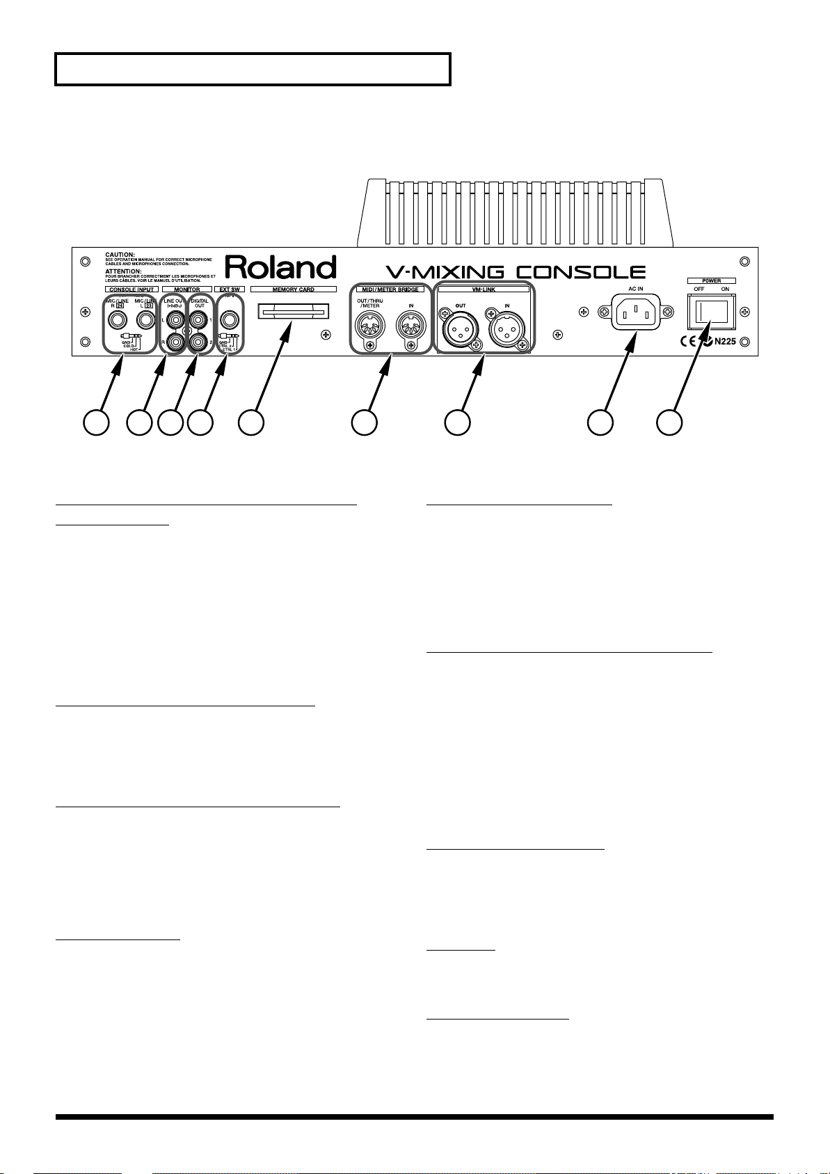
■
Rear panel
fig.01-8
1 2 3 4 6 7 8 95
1...CONSOLE INPUTs MIC/LINE L and
MIC/LINE R
Jacks for inputting a pair of analog audio signals to the
console. These TRS jacks—available for both balanced and
unbalanced signals—support a wide range of signals, from
a microphone level to line level. Typically, these are
connected internally to INPUT Channels 23 and 24, though
they can be re-patched. When the talkback system is in use,
the right channel “R” (the both L and R channels when
stereo linking) is used exclusively for an external talkback
microphone and is thus not available for other purposes.
MONITOR LINE OUTs L and R
2...
Jacks for outputting analog stereo signals for studio
monitoring. You can adjust the jacks’ output level using the
DIGITAL/MASTER knob or the LINE OUT LEVEL knob on
the front panel.
3...
MONITOR DIGITAL OUTs 1 and 2
Jacks for outputting digital stereo signals for studio
monitoring. Signals at these jacks are nominally the same as
at the analog LINE OUTs. Their output level can be changed
using the DIGITAL/MASTER knob on the front panel. (The
level of the MONITOR DIGITAL OUTs 1 and 2 is not be
changed using the front-panel LINE OUT LEVEL knob.)
EXT SW jack
4...
Generally connected to a foot switch. Two BOSS FS-5U foot
switches can be connected using a branch cable. The
functions of both switches can be selected on the FADER/
SW screen. GPI jack-switching (38) is also available.
5...MEMORY CARD slot
Slot for a “SmartMedia”-format memory card onto which
you can store various types of mix data. The SmartMedia
format is the same one used by many digital cameras. A
memory card must be inserted to use the Scene or Automixing features.
* One memory card is included.
6...
MIDI/METER BRIDGE connectors
Allow for the connection of MIDI devices or the optional
MB-24 meter bridge (sold separately). IN (for inputting)
receives MIDI data. The OUT/THRU/METER jack can be
switched between OUT—for MIDI data generated by the
console—and THRU, which passes on received MIDI data
unchanged.
Level information for an MB-24 meter bridge can also be
transmitted from the OUT/THRU/METER connector.
When the jack is switched to THRU, output of level
information to the meter bridge is de-activated.
7...VM-LINK connector
Connects the mixing console to the processor. Two AES/
EBU digital audio cables (3-pin, XLR connectors) are
utilized for a two-way connection. Can also be used to daisy
chain multiple consoles.
AC IN
8...
Accommodates the power cable that supplies AC power to
the console.
POWER switch
9...
Turns the entire system on.
20
Page 21
Chapter 1 Introduction
Before Operation
■
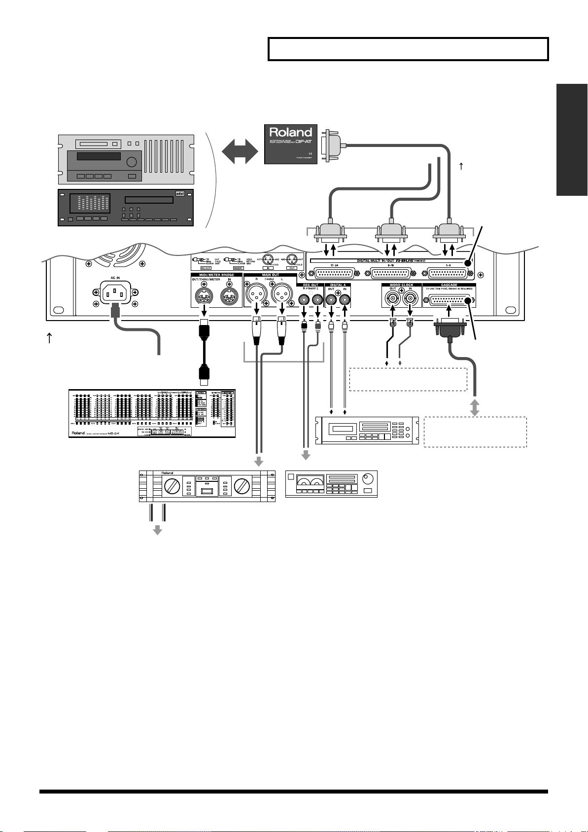
Connections
Connect up the necessary equipment after referring to the connection diagrams on
the next page.
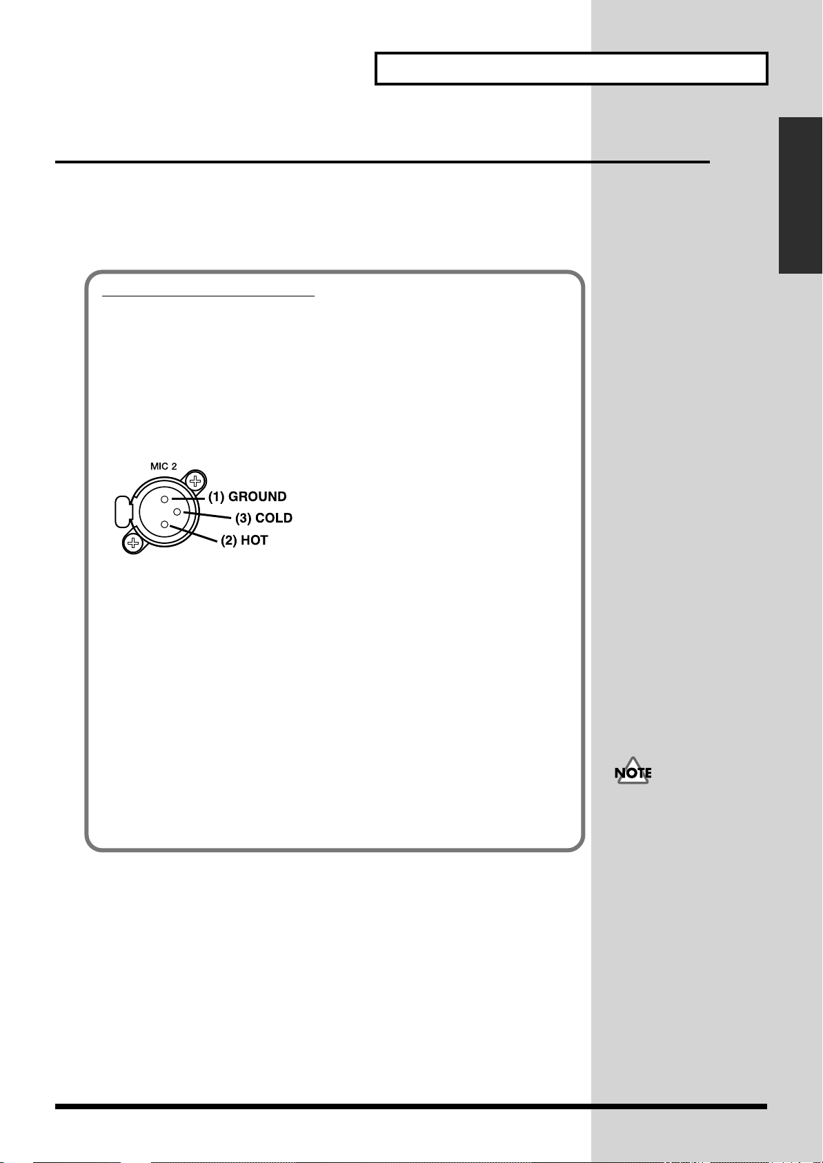
Precautions on connection
Be sure to follow the precautions below. Otherwise, you risk causing malfunction or
damage.
• To prevent malfunction and/or damage to speakers or other devices, always
turn down the volume, and turn off the power on all devices before making
any connections.
• The pin assignment for the XLR type connectors is as shown below. Before
making any connections, make sure that this pin assignment is compatible
with that of all your other devices.
fig.01-10a
Chapter 1 Introduction
• To connect this console to the processor, use the VM link cable (AES/EBU
digital audio cable) supplied with the processor.
• R-BUS is the same standard as RMDB2 or RMDBII. Even if “RMDB2” or
“RMDBII” is indicated on your DIF-AT, it can be used without any
problems.
• When connecting a digital multitrack tape recorder like an ADAT or
TASCAM, install the VM-24E beforehand. For details, refer to the operation
manual of the processor (VM-7200/7100).
• When connecting the processor in cascade, install the VM-24C beforehand.
For details, refer to the operation manual for the processor (VM-7200/7100).
• Howling could be produced depending on the location of microphones
relative to speakers. This can be remedied by:
1. Changing the orientation of the microphone(s).
2. Relocating microphone(s) at a greater distance from speakers.
3. Lowering volume levels.
When connecting various
components to the
processor, be sure to refer
to the processor’s owner’s
manual.
21
Page 22
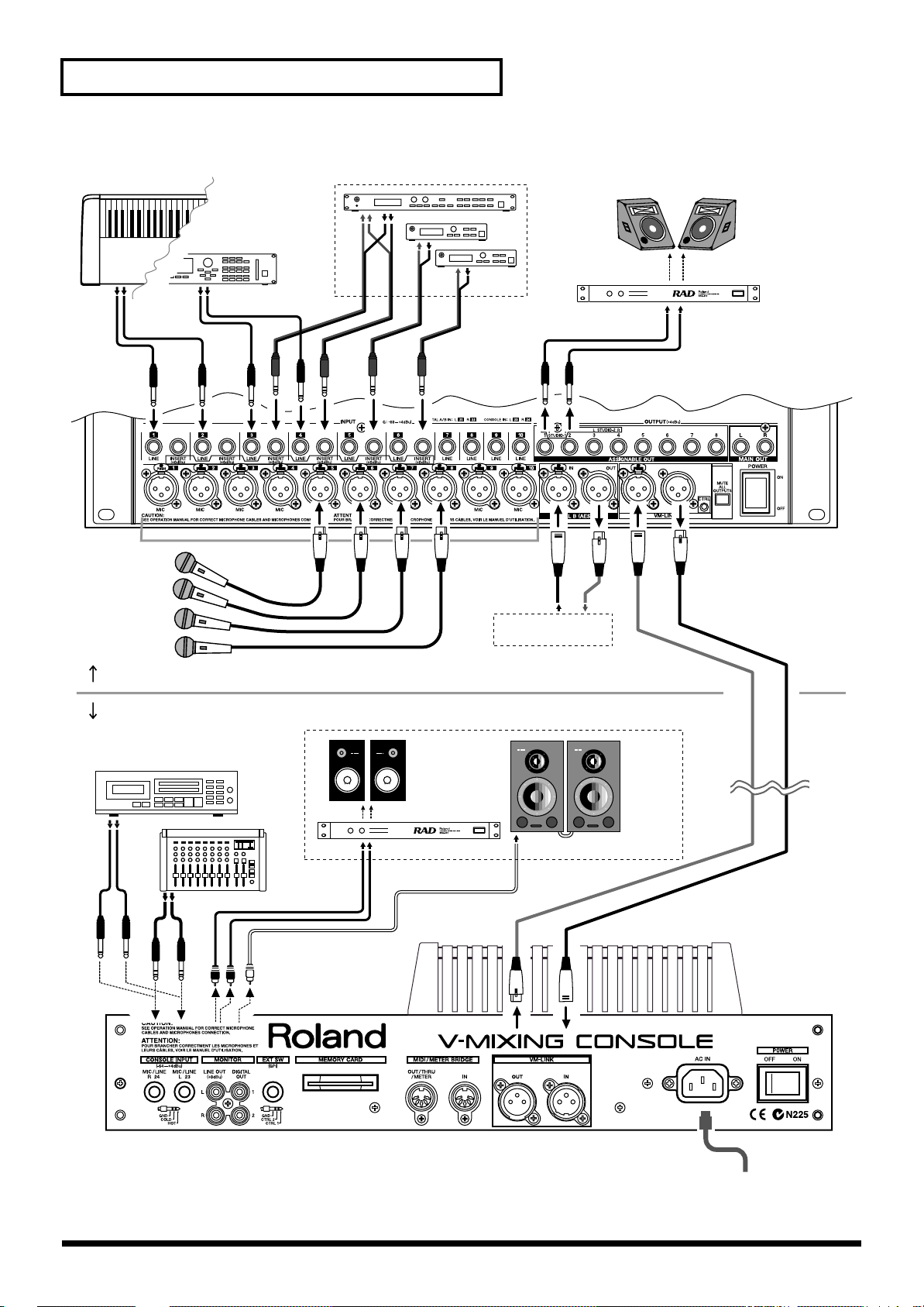
Chapter 1 Introduction
fig.01-10e
Synthesizer,
Sound Module, etc
Channel Insert (Effects Processor)
Monitor Speaker
345 6
123
Microphone
4
5678
Front Panel on the Processor
Rear Panel on the console
Microphone, Sub Mixer,
MD/CD Player
Branch Cable
(e.g. PCS-31)
Monitor in the
Control Room
Monitor Amp,
Headphone Amp
for players
Digital
Audio
Input/Output
AES/EBU jack
on pro audio device
Speaker
Amp
Digital
Powered
Speaker
(Roland DS-90 etc.)
Use two AES/EBU
Digital Audio Cables.
(max. 200 m)
AC
outlet
22
Page 23
Chapter 1 Introduction
fig.01-11e
Digital Multi-track Tape Recorder
(TASCAM/ADAT)
Rear Panel
on the Processor
MB-24 (Option)
AC
power supply
8 ch
Main
Output
Roland DIF-AT
(Interface Box)
R-BUS
Cable
Word Clock connector on
digital recorder or similar device
Chapter 1 Introduction
To R-BUS compatible
device
VM-24E
(Option)
VM-24C
(Option)
Cable supplied
with the VM-24C
Power Amp
PA Speaker
Digital Input/Output
the Processor Processor
to be connected in cascade
(VM-7200/7100)
DAT/MD Recorder, etc.
Analog Input
Tape Recorder,
MD Recorder, etc.
23
Page 24
Chapter 1 Introduction
■
Turning the power on/off
Turn each device on in the following sequence. After all devices are turned on, adjust
the volume of each.
Precautions on turning the power on
• Once the connections have been completed (21), turn on power to your
various devices in the order specified. By turning on devices in the wrong
order, you risk causing malfunction and/or damage to speakers and other
devices.
• This unit is equipped with a protection circuit. A brief interval (a few
seconds) after power up is required before the unit will operate normally.
• Turn the power on after lowering the volumes of the console and the
connected audio equipment. If the volumes are raised, the audio equipment
may malfunction due to current overload the instant the power is turned on.
• Even with the volume lowered, a slight amount of sound may be heard
when the power is turned on. This should not be a cause for concern.
1.
Digital multitrack tape recorder
2.
Processor
The CTRL indicator blinks during startup. After the startup process is completed,
the indicator comes on.
3.
Console
After the confirmation message appears, press [F2] (START) to begin the startup
process.
4.
Digital-connected equipment (e.g., DAT, MD recorder or hard disk
recorder)
5.
Analog-connected equipment (e.g., musical instruments, sound modules,
effects, microphone, CD player, MD player or tape recorder)
6.
Audio equipment such as amplifiers and speakers
Turning the power off
Turn each equipment off in the opposite sequence in which it was turned on.
Points to check before turning the power off
Turn the console on after
making sure that the CTRL
indicator has come on.
In order to turn the power
of the entire system on,
press [F4] (ON)
(highlighted) to
automatically start the
console startup process in
60 seconds.
24
• Make sure that Automix has been stored in the memory card.
→ Although Automix is stored in the console memory, it is, however, lost
after the power is turned off.
• The volumes of the console and the connected audio equipment are at
the lowest level.
→ If the volumes are raised, the audio equipment may malfunction due to
current overload the instant the power is turned off.
Page 25
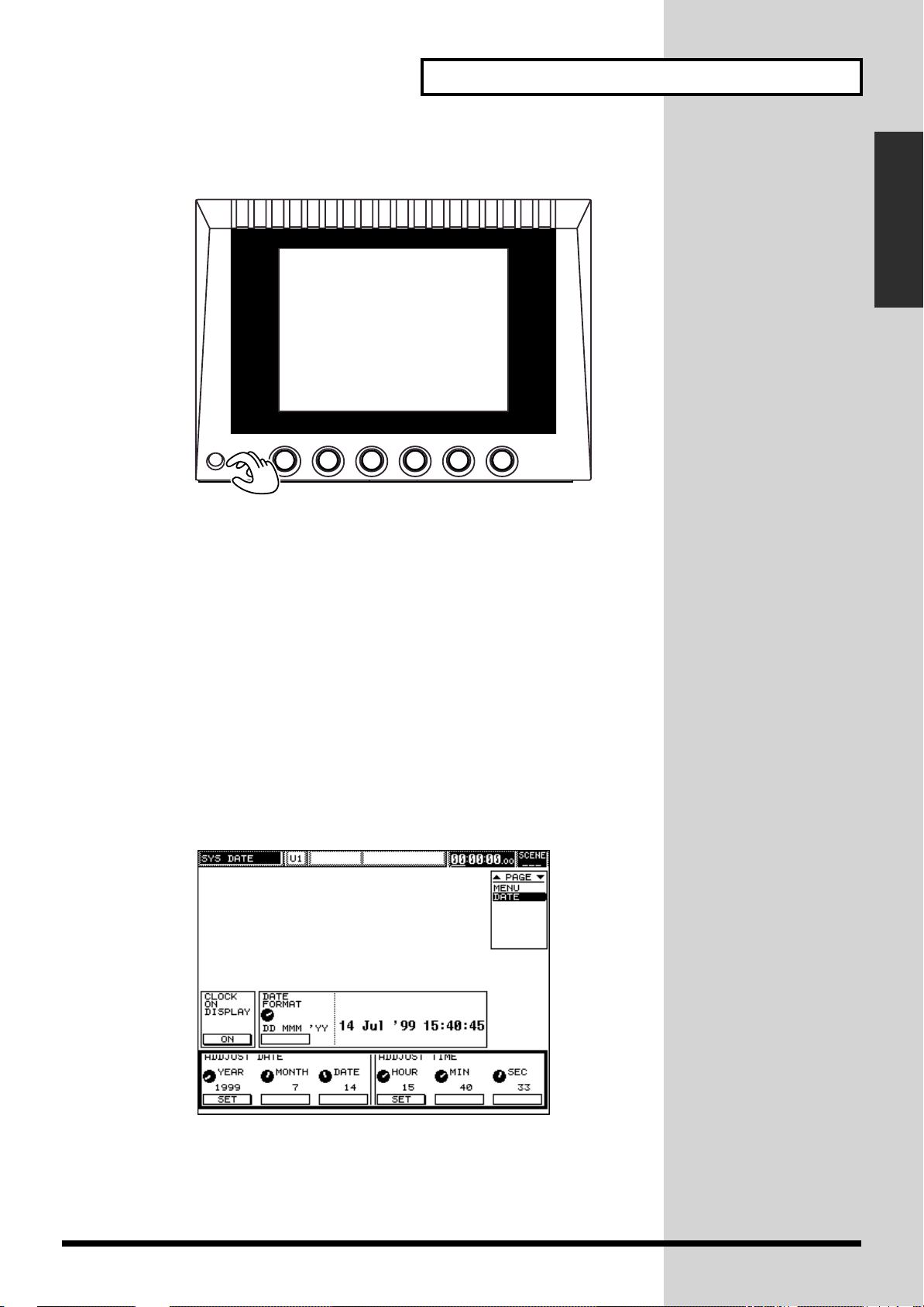
Chapter 1 Introduction
■
Adjusting the display’s contrast
fig.01-12
CONTRAST
The display may be blurred immediately after the power is turned on, after a long
period of operation, or depending on the setup location. In this case, turn the
CONTRAST knob on the lower left of the display to adjust it.
Chapter 1 Introduction
■
Adjusting internal clock
This system has a built-in clock. When a project is stored, information on when
operation has been performed (time stamp) is also written automatically. When
turning the power on for the first time after purchase, adjust this internal clock.
1.
While holding down [SHIFT], press [PROJECT].
2.
Press CURSOR [UP] to move the cursor upward.
3.
Press [F5] (DATE).
The internal clock setting screen appears.
fig.01-13
4.
Press CURSOR [DOWN] to move the cursor to [ADJUST DATE/ADJUST
TIME].
25
Page 26
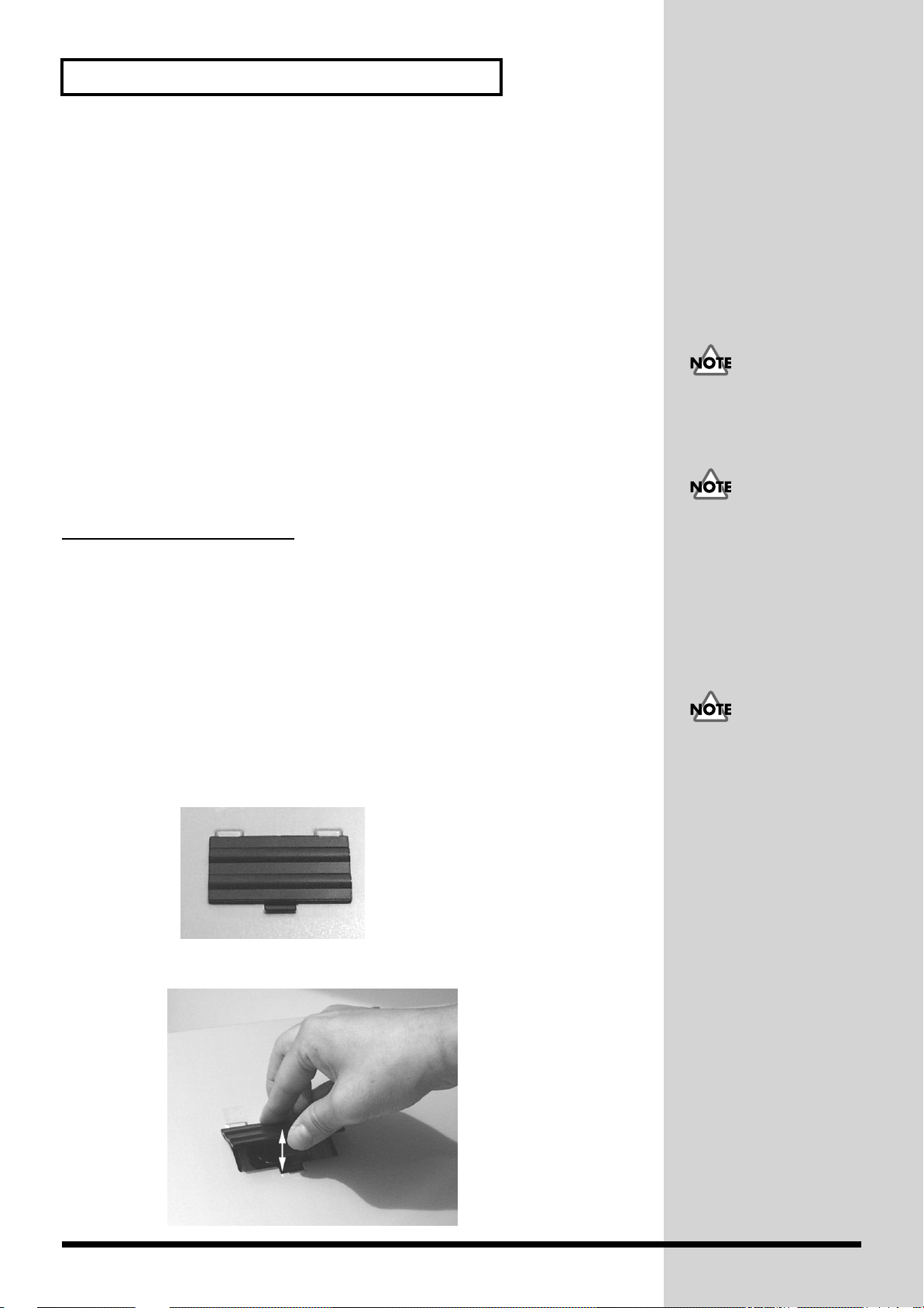
Chapter 1 Introduction
b
5.
Set the year, month and date.
After setting the year, month and date using the V1 (YEAR), V2 (MONTH) and V3
(DATE) knobs, press [F1] (SET) to confirm them.
6.
Adjust the time.
After setting the hour, minute and second using the V4 (HOUR), V5 (MIN) and V6
(SEC) knobs, press [F4] (SET) to confirm them.
7.
This completes the internal clock setting. After the above setting, adjust the
time as necessary.
Press CURSOR [UP] to move the cursor to [CLOCK ON DISPLAY/DATE
FORMAT].
• Display the clock at the upper right of the screen: Press [F1] (ON) to
highlight it.
• Change the date display format: Turn the V2 (DATE FORMAT) knob to
select a desired format.
8.
Press [LEVEL METER] to call the initial screen.
How to replace the
A
lithium battery
the power for maintaining information about certain parameters. Once this battery
gets weak, the unit may no longer be able to reliably perform the time management
functions for data, or return to the state it was in before power was turned off. If you
suspect that the battery has worn down, try switching the console’s power off, then
on again. If you see a message warning that the battery is depleted, promptly change
the battery, following the procedure below.
battery
inside the unit powers its time-keeping functions, and provides
When the clock is
displayed, the current
position of the time code
cannot be checked.
Since the internal clock are
attery powered, the above
operation is not required
each time the system is
turned on. If the internal
clock gains or loses for
some reason, however,
adjust the time by referring
to the above procedure.
fig.01-14
fig.01-15
1.
Store the current settings onto a memory card (52).
2.
Turn the power off, and unplug the power cable from the outlet.
3.
Turn the console upside down, and locate the battery cover.
4.
Remove the battery cover as shown below.
A CR2032 lithium battery is
used for the console. This
type of battery is available
at an electric appliance, or
similar store.
26
Page 27
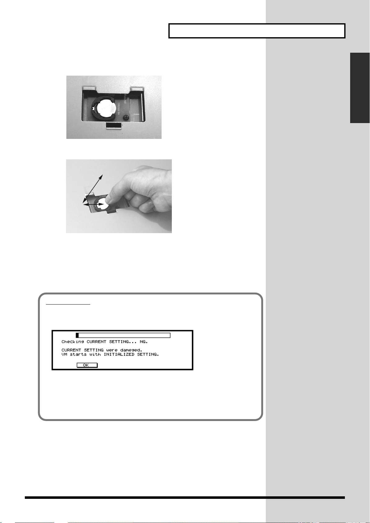
fig.01-16
fig.01-17
5.
The battery should now be visible, as shown in the following.
6.
Replace the old battery with a new one.
Chapter 1 Introduction
Chapter 1 Introduction
7.
8.
9.
fig.01-17a
Put the battery cover back on.
Turn the power on and set the time for the internal clock (25).
Using the memory card you used for backup in step 1, restore the previous
state (54).
IMPORTANT
Following message may appear in the display, for instanse, when you turn on the
console after replacing the battery.
This message is NOT for warning any malfunction or breakdown. In this case, you
need to initialize the internal memory. Please execute the "Factory Reset"
procedure (p. 33).
Implementing factory reset deletes all user settings on the console. Please store the
necessary data (such as user-customized libraries) in the memory card beforhand
(p. 44).
27
Page 28
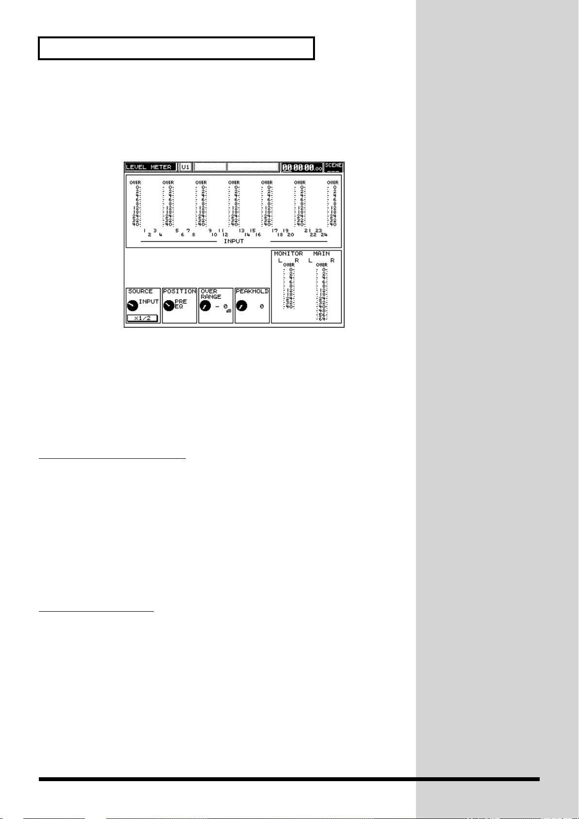
Chapter 1 Introduction
■
If you get lost
If an unfamiliar screen appears, or you forget to which step you have proceeded,
press [LEVEL METER]. This calls the initial screen. Try again from the beginning on
this screen.
fig.01-18
■
Preparing a memory card
Before any operation, be sure to create a new project on the memory card. If no
project is prepared beforehand, scenes, Automix or libraries are not stored. Before
using a new memory card or one that has already been used for other purposes, be
sure to format it.
Formatting a memory card
1. While holding down [SHIFT], press [PROJECT].
2. Press CURSOR [DOWN] to move the cursor downward.
3. Press [F6] (MEMORY CARD) and [F2] (FORMAT), in that order.
4. Press [F5] (OK).
5. After the confirmation message appears, press [F5] again.
6. After formatting is completed, press [F6] (EXIT).
Creating new project
1. Press [PROJECT].
2. Press CURSOR [DOWN] to move the cursor downward.
3. Press [F2] (NEW).
4. Press [F2] (CREATE), followed by [F5] (OK).
5. After creation is completed, press [F6] (EXIT).
28
Page 29
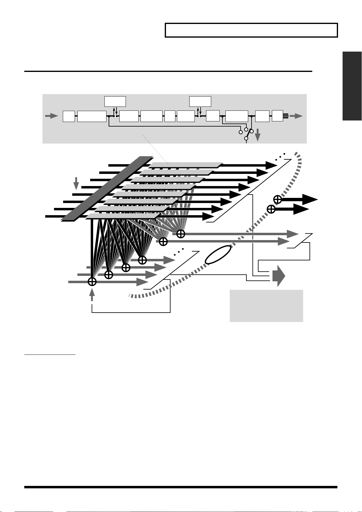
Chapter 1 Introduction
Internal Signal Flow
The diagram below provides an overview of the audio signal flow. For details, refer
to the “Block Diagram” attached to the processor (VM-7200/7100).
fig.01-9e
Effect
INPUT
ATT
Analog Input
Digital Input A, B
(R-BUS Input)
Patchbay
Phase
normal/invert
Insert
Phase
Delay
Feedback
Delay
HPF
Effect
Insert
4-band
EQ
Mute
Input Cannel 1–24
(Multi In Channel 1–24)
Channel
Level
to Main Out Bus
Main
Pan
SW
to Cue and Flex Bus
Main Out L, R
Chapter 1 Introduction
Flex Bus 1–12
Input channels
● INPUT...1–24
The following input jacks can be assigned to input channels:
• Twenty analog input jacks on the VM-7200 mixing processor (10 on VM-
7100)
• Stereo digital IN on the mixing processor (a choice of A and B stereo inputs)
• Two analog input jacks on the console
● MULTI IN...1–24
Multi-channel audio signals can be input from external equipment—such as multitrack recorders—via these channels. The correspondence between input signal
channel numbers and MULTI IN channels can be re-patched internally.
* In order to use MULTI IN channels, a VM-24E (sold separately) must be
connected to the mixing processor in order to add an R-BUS connector I/O
terminal.
From Flex Bus 1–8 to Cue and Flex Bus 1–12
Cue L, R
MIX
Assignable Out
Digital Out A, B
Multi Out (R-BUS) *
Flex Bus Out 5–12 **
Monitor Out **
* This is not available for the MULTI IN channel.
** Only VM-7200
29
Page 30
Chapter 1 Introduction
Buses/
output routes
● MAIN OUT
Output of the overall stereo mix containing all desired channels, to be sent to the
master recorder or the main PA amplifier.
Signals can be sent from all input channels and Flex buses.
In addition to the dedicated output terminals (MAIN OUT and REC OUT), signals
can be directed to any ASSIGNABLE OUT, DIGITAL OUTs A and B and/or any
MULTI OUT.
● Flex Buses 1–12
A Flex Bus is a multi-purpose bus through which signals can be sent to another bus,
to internal effects processors or to external devices. Flex buses are capable of sending
signals from all input channels as well as Flex buses 1 through 8. Any ASSIGNABLE
OUT, DIGITAL OUTs A and B, and MULTI OUT can be selected for outputting Flex
Bus signals to external destinations. In the case of the VM-7200 processor, dedicated
output jacks are also available for Flex buses 5 through 12.
● Cue
Stereo bus used mainly for monitoring. Signals can be sent to the cue bus from all
input channels and Flex buses.
Cue signals can be output from MONITOR OUT and PHONES jacks to external
monitoring amplification equipment. They can also be routed to any ASSIGNABLE
OUT, DIGITAL OUTs A and B, or any MULTI OUT.
The MONITOR OUT
terminal can output a
variety of different signals.
30
Effects
Internal effects can be inserted into input channels, MULTI IN signals, Flex buses,
the MAIN OUT and MONITOR OUT. Input channels can also send signals to the
internal effects via Flex buses; the outputs of the effects can be routed into the main
mix or to available input channels. For more information, refer to p. 110.
General-purpose effects
A mixing processor is factory-equipped with two stereo effect systems, enabling the
use of 39 types of effect algorithms. Up to three VS8F-2 effect expansion boards (sold
separately) can be added to the system—providing as many as eight stereo effects
processors.
Master effect
One effect processor is provided exclusively for MAIN OUT and MONITOR OUT
insertion. This processor enables the use of three types of effect algorithms, and is
useful for final mastering effects or for speaker modeling.
The insertion point is
determined by the effect
type (p. 110). When the
send/return method is
used, the Flex Bus that
corresponds numerically to
the effect is used to send
signals to the effect. For
detailed effects
information, refer to the
descriptions starting on p.
112.
Page 31
Chapter 1 Introduction
b
About Digital Connections and the Master Clock
■Digital sound device and master clock
To share digital audio signals between this system and any external digital device, a
common master clock signal (word clock) must be used.
Master clock (word clock)
Digital sound devices such as this system, CDs, DAT recorders and digital multitrack recorders, generally operate based on internal master clock signals called
“word clocks.”
To exchange digital audio signals between digital devices, word clocks from one of
the devices must be used as the timing foundation of all other connected digital
devices. When a device is successfully receiving timing information from word
clocks generated by another device, it is referred to as being “locked to (or
synchronized with) external word clocks.” Word clocks are supplied via a digital
audio I/O or dedicated word clock terminal.
* Note: If digital devices are not synchronized properly, undesirable digital noise
and/or intermittent unwanted sound may result, preventing the digital audio
signals from being exchanged successfully.
Chapter 1 Introduction
The following seven word-clock sources are available:
INTERNAL... Internal clock of the first mixing processor (1st UNIT).
MULTI 1–8... Equipment to which the 1st connector (1 to 8) of the R-BUS
is connected.
MULTI 9–16... Equipment to which the 2nd connector (9 to 16) of the R-
BUS is connected.
MULTI 17–24... Equipment to which the 3rd connector (17 to 24) of the R-
BUS is connected.
CASCADE... Second mixing processor (2nd UNIT) connected in cascade.
WORD CLOCK IN... Clock supplied from the WORD CLOCK IN terminal.
DIGITAL IN... Equipment connected to the IN terminal of DIGITAL A or
B.
INTERNAL word clock is selected by default. This setting can be changed on the
digital I/O screen ([SHIFT] + [PROJECT] → CURSOR [DOWN] → [F1]). For details,
refer to 32.
The R-BUS connector is
added by installing a VM24E (sold separately). To
use two processors, a
cascade connector (VM-24C
sold separately) is required.
VM link (p. 247),
R-BUS (p. 243),
Cascade (p. 233)
The console is always
supplied with word clocks
y the first mixing
processor. When the
processor is synchronized
to word clocks of another
device, the console is also
supplied with these clocks
via the VM link.
31
Page 32

Chapter 1 Introduction
■DIGITAL A and B terminals and reception of
word clocks
DIGITAL Ins—the DIGITAL A connector on the rear of the processor and DIGITAL
B jack on its front—can receive digital audio signals from digital equipment to which
they are connected, even when some other device is the source of the system’s word
clocks. When the system’s timing is based on word clocks received, for example,
from a multi-track recorder to which the R-BUS jack is connected, additional digital
audio can still be received at the DIGITAL IN terminal. In such a case—when the IN
terminal of DIGITAL A or B is used for digital audio only—“DIGITAL IN” need not
be selected as the word clock source.
■Word clock connector
When a word clock output connector is available, it is recommended that the word
clock connector on the rear of the processor be used. Although word clocks can be
supplied from R-BUS or DIGITAL IN A or B via a digital audio cable, audio signals
are more stable when word clocks are supplied directly from the source.
■Checking the overall system
Apart from the aforementioned word clock, there are some important settings
related to digital input/output. When handling audio signals via digital connection
with other devices, make the necessary changes.
For this reason, sample rate
converters are built into the
DIGITAL A and B
terminals. If the digital
audio at these inputs is a
different sample rate than
the system word clocks, the
difference will be
accommodated for by these
converters, leaving the
digital audio signals free
from noise or dropouts.
Settings on the digital I/O screen
1. While holding down [SHIFT], press [PROJECT].
2. Press cursor [DOWN], then [F1] (DIGITAL I/O).
This calls up the digital I/O setting screen.
fig.01-101
1
... Digital input connector selection
Select either DIGITAL A IN (coaxial) on the rear of the processor, or DIGITAL B IN
(XLR connector) on the front. Place the cursor, select with the V1 knob and enter with
[F1] (SET).
32
Page 33

2
... Type 1/2 and copy protect switches
“MODE” specifies whether the digital audio signal to be output is and AES/EBU
broadcasting studio (TYPE 1), or a consumer-use digital audio device (TYPE 2). Place
the cursor, select with the V3 knob and enter with [F3] (SET).
Turning the “COPY PROTECT” on turns on the SCMS, thereby blocking digital
copying of the output signal. Place the cursor and turn the switch on or off with [F4].
3
... Word clock source
Specifies the reference device of the word clock (32). Place the cursor, select with the
V1 knob and enter with [F1] (SET).
4
... Word clock in terminator
This switch needs to be turned on if the system is at the end of the word clock, so that
the word clock is transmitted correctly. Place the cursor and turn the switch on or off
with [F3].
5
... Internal sampling rate
Sets the sampling rate (sampling frequency) internally. Sampling rates of 48 kHz,
44.1 kHz, and 32 kHz can be selected. Place the cursor, select with the V1 knob and
enter with [F1] (SET). After operation, some time may be required to finish changing
the settings.
Chapter 1 Introduction
Chapter 1 Introduction
The “SCMS” (Serial Copy
Management System) is a
copyright protection
function for home digital
audio devices, such as MD
recorders. It prohibits
second generation and after
copying with digital
connections.
Restoring the Original Factory Settings (Factory Reset)
■Factory reset procedure
Implement the following procedures to return all the parameter values to those set
prior to shipping. Note that implementing factory reset deletes all user settings on
the console.
1. Turn off the console’s power.
2. While holding down [PROJECT] and [F1], turn the power on again.
3. When the factory reset screen is displayed, press [F1].
All the parameter values will be returned to those set prior to shipping.
The volume of connected
amplifiers must be lowered
or amplifier power turned
off.
33
Page 34

Chapter 2 Basic Operations and Their Settings (System/Project)
b
Basic Operations
■ Screen descriptions
fig.02-01
1 2 3 4 5 6
7
1
Screen Title
2
Processor currently targeted
3
Number of the effect library used
4
Screen subtitle
5
Current position (time code)
6
Number of scene currently selected
7
Parameter display section
(displayed only on the effect setting screen)
Subtitle shows the section,
or the name of the effect
algorithm used, depending
on the screen displayed.
Current position can also
e shown in terms of
“measure, beat, and clock.”
Set the TIME DISPLAY
MODE on the DISPLAY
screen of the system to
“MEASURE/BEAT.” The
current time can also be
shown instead of current
position. Turn on the
CLOCK ON DISPLAY on
the DATE screen of the
system.
34
Page 35

■ Setting parameters
To set parameter values, move the cursor to the target parameter, then set the
parameter values using the V1 to V6 knobs/fader/[F1] to [F6].
Moving the cursor
The cursor is used for grouping some parameters together as modification targets.
To move the cursor, press either CURSOR [UP], [DOWN], [LEFT] or [RIGHT].
fig.02-02
Chapter 2 Basic Operations and Their Settings (System/Project)
Pressing CURSOR [LEFT]
or [RIGHT] while holding
down [SHIFT] changes the
unit (hour, minute, second,
or rate) for changing the
current position.
Chapter 2 Basic Operations and
Their Settings (System/Project)
Changing values
The method of changing values varies depending on the parameter. The following
rules apply, so keep them in mind.
The value of parameters marked can be changed by turning the V1 to V6 knobs.
The value of parameters marked can be changed by switching the [F1] to
[F6] on (highlighted) or off (normal indication).
The value of parameters marked can be set by turning either of the V1 to V6
knobs to select the value and pressing either of the [F1] (SET) to [F6] (SET) having the
same number to determine it.
(You can directly modify some parameters with [F1] to [F6] (SET).)
The value of parameters with a fader indicated can be changed by the fader. When
the cursor is placed at the fader, the value can also be changed by turning the V1 to
V6 knobs.
35
Page 36

Chapter 2 Basic Operations and Their Settings (System/Project)
Level Meter Settings
The level meter is a screen for checking the level of the input or output signal at each
point. Since this screen always appears right after powering-on, it also functions as
a general screen. If any unfamiliar screen appears or you get lost, press the [LEVEL
METER] to return to the level meter screen and start the operation over again.
fig.02-04
1
2
3
1
Level meter 1
Checks level specified at and of each channel if the specified level is
applied.
2
Level meter 2
Level of the cue and main buses can be checked by MONITOR and MAIN,
respectively.
3
SOURCE
Selects the section (Input, Multi In or Flex Bus) of which the level is checked.
4
x1/2 switch
Normally, level changes can be checked within the range of 0 to -40 dB (0 to -64 dB
for Main). Turning this switch on narrows the range by half, enabling level changes
to be checked more precisely. It is just like a zoom-in function.
5
POSITION
Determines the point (original sound, sound before or after being passed through
the fader) at which the level is checked.
6
OVER RANGE
In order to prevent sound deterioration, an “OVER” warning indication appears if
the specified value is exceeded. This determines the value.
7
PEAK HOLD
Determines the time (1 to 7 seconds) during which the peak status of the sound level
is continuously indicated when the sound level reaches the maximum value (peak).
To keep the peak status indicated until the sound level reaches the next peak, set this
to “CONTINUE.” With some fast tempo music, the peaks are missed, or cannot be
indicated on time. In such cases, set a larger value or set it to “CONTINUE.”
4 5 6 7
3 5
When using the MB-24
(level meter bridge), its
indication also follows the
setting of this switch.
“OVER” is not displayed
when PEAK HOLD is set to
“0.”
36
Page 37

Chapter 2 Basic Operations and Their Settings (System/Project)
Settings for the Panel (Knobs and Display)
Here, you can use the buttons or foot switch to make settings affecting the operation
of the unit.
1. While holding down [SHIFT], press [PROJECT].
2. Press CURSOR [UP], then press [F3] (FADER/BUTTON).
The SYSTEM FADER/SW screen shown below is displayed.
fig.02-05
2 3
1
4
7
Chapter 2 Basic Operations and
Their Settings (System/Project)
8
1
PAN CURVE TYPE
Depending on the sound location, the volume may be unstable. This setting is used
to correct such unstable sound volumes. Normally, it is set at -3 dB. When it is set at
0 dB, no sound volume adjustment is performed.
fig.02-06
2
PREAMP GAIN ADJUST MODE
LEVEL
0dB
To ensure high quality sound, input gain is adjusted in this system using an
electronic relay method rather than VCA.
• NOISELESS: Volume is controlled, and noise in relay switching is reduced.
• CONTINUOUS: No special processing is carried out when relays are switched,
3
FADER MOTION DEMO
Performs demonstration to check the fader motion.
5 6
LEVEL
-3dB 0dB
RIGHTCENTERLEFT
0dB
thus preventing interruption of the sound.
RIGHTCENTERLEFT
Depending on the
connected device, direct
current voltage may be
contained in the signal,
which may result in noise
during gain switching. In
such cases, set the system
to “NOISELESS.”
4
SHIFT LOCK
Normally, the [SHIFT] button only functions while it is being pressed. When it is set
to “LOCK,” the [SHIFT] button keeps functioning while the [SHIFT] indicator is on.
To release this function, press the [SHIFT] button again to turn the indicator off.
When you frequently need to use [SHIFT], the “LOCK” setting is very convenient.
37
Page 38

Chapter 2 Basic Operations and Their Settings (System/Project)
5
TALKBACK BUTTON
Determines how the [TALKBACK/SLATE] works. To set it so that it only functions
while the button is held down, and is turned off when the button is released, set it to
“MOMENTARY.” To set it so that it is turned on by pressing the button, and is
turned off by pressing the button again, set it to “LATCH.”
6
LED TYPE
Normally, the channel status and [STOP] auto-mixing indicators light in green.
However, it is sometimes difficult to see these green indicators outdoors or in bright
locations. In this case, set the LED TYPE to “TYPE2.” By setting it to “TYPE2,” a red
indicator blinks instead.
7 8
, EXT SW1/2 (External switch 1/2)
By using the foot switch or GPI connected to the EXT SW jack on the rear panel,
play/stop of Automix, scene changing and talkback can be controlled.
TYPE: Determines whether to use the foot switch or the GPI. As for the foot
switch, use a Roland DP-2 (pedal switch) or a BOSS FS-5U. Also, the use
of a branch cable (PCS-31; sold separately) enables two functions to be
controlled.
The EXT SW1 controls the
TIP settings, and the EXT
SW2 controls the RING
settings.
fig.02-07e
White (TIP)
Branch Cable:
PCS-31 (sold separately)
Red (RING)
What is GPI?
GPI (General Purpose Interface) is a control connector provided on professional/
consumer-use video peripheral equipment, such as editing machines and titling
devices. By connecting a device that supports GPI, the same function as the foot
switch can be controlled from the external device.
FUNCTION: Determines which function to control with the foot switch.
When using a BOSS FS-5U,
set the polarity switch as
follows.
38
• PLAY/STOP: Starts or stops synchronization.
• PLAY/TO TOP: Starts or returns to the beginning of
synchronization.
• PUNCH I/O (REC): Manual punch-in recording of Automix.
• NEXT SCENE: Switches you to the next scene.
• PREV SCENE: Switches you to the previous scene.
• NEXT LOCATE: Selects the next locate number.
• PREV LOCATE: Selects the previous locate number.
• TALKBACK/SLATE: Performs talkback or slate.
Page 39

Chapter 2 Basic Operations and Their Settings (System/Project)
Connection Setting of Processor and Console
Up to two processors and two consoles can be connected to this system. The
following screens are for checking and setting the overall system.
■ Checking the overall system
1. While holding down [SHIFT], press [PROJECT].
2. Press CURSOR [UP], then [F1] (SYSTEM CONFIG).
The System Configuration Screen appears.
fig.x-x1
Chapter 2 Basic Operations and
Their Settings (System/Project)
1
Connection status of the console itself
CONSOLE x1 Number of consoles being used by the entire system (1 to 2)
PROCESSOR x1 Number of processors being used by the entire system (0 to 2)
This CONSOLE: Operation of the console (MASTER/SLAVE)
CASCADE: Existence of cascade kits (VM-24C)
(Connected! (present)/Nothing (not present))
VM-LINK: Connection status to the VM link In of the console
(Connected!/Unconnect)
2
1st UNIT... Connection status of the first processor
R-BUS BOARD VM-24E installed/not installed (checked when present)
MULTI 1–8
MULTI 9–16 Existence of devices connected to the second R-BUS (checked when
MULTI 17–24 Existence of devices connected to the third R-BUS (checked when
VS8F-2 (A) Effect expansion (A) installed/not installed (checked when present)
VS8F-2 (B) Effect expansion (B) installed/not installed (checked when present)
VS8F-2 (C) Effect expansion (C) installed/not installed (checked when present)
3
2nd UNIT... Connection status of the second processor
Same as the 1st UNIT.
Existence of devices connected to the first R-BUS (checked when present)
present)
present)
4
1st UNIT... [F1] MASTER (SET)
Button for setting the console as the master (see next section).
The connection status of the console, processors and optional devices are displayed
on this screen. It is checked when the console is turned on. It is also re-checked when
[F1] is pressed on the above screen.
4
39
Page 40

Chapter 2 Basic Operations and Their Settings (System/Project)
■ When using two consoles
Up to two consoles can be used simultaneously by ring connecting the VM link.
Using two consoles enables simultaneous control from two locations, such as a seat
in the audience and stage side.
fig.x-x2
VM-7200/7100 VM-7200/7100
CASCADE
OUTIN
VM-LINK
OUT IN OUT IN
VM-C7200/
VM-C7100
When using two consoles, one is used as the Master Console with full functions,
and the other is used as the Slave Console which follows the master. On the slave
console, some functions, such as selection of the level meter source and setting of
synchronization-related parameters are blocked. The “Function is Blocked. (This is a
slave console.)” message appears when operations are blocked and they cannot be
performed.
Basically, the console that is turned on after the other console is the master.
When the master console is turned on, it informs the other console that it is the
master, and also transfers all the mixer settings belonging to the master console to
the other console and the processors. The other console on receiving such
information functions as the slave.
To re-select the master console, press [F1] MASTER (SET) on the system
configuration screen mentioned earlier. The same console turning-on operation is
performed, and the console becomes the master.
VM-C7200/
VM-C7100
VM link (p. 247)
This “Master” and “Slave”
are not related to the
“Master” and “Slave”
settings for
synchronization (time code
and MIDI clock) or remote
control (MMC).
40
Audio through function of the console
Audio signals for console-in or talkback are sent via from the console the VM link
line. Generally, with ring connection of the two consoles, such audio signals are
stopped at the first connected device and do not reach the next one. Therefore,
problems such as talkback sound stops at the second console and does not reach the
processor.
To prevent such problems from occurring, consoles are provided with a function to
pass the sound coming through the VM link line to the next connection target (VM
link audio through function). In case of a ring connection, set this function to
“THRU” when necessary. The switch for this is on the screen for settings related to
cascade connection, explained in the next “Settings related to cascade
connection” section.
Page 41

Chapter 2 Basic Operations and Their Settings (System/Project)
■ Settings related to cascade connection
The second processor (2nd UNIT) is cascade connected to the first processor,
enabling the number of input channels to be greatly increased. To control the second
processor from the console, press [2nd UNIT] on the panel to turn it on.
For cascade connection, a
VM-24C (sold separately)
needs to be installed on the
processor. For installation,
see the manual for the
processor (VM-7200/7100).
Chapter 2 Basic Operations and
Their Settings (System/Project)
Settings related to cascade connection can be made on the following screen.
Settings related to cascade connection
1. While holding down [SHIFT], press [PROJECT].
2. Press CURSOR [UP], then [F1] (SYSTEM CONFIG).
3. Press [PAGE DOWN].
fig.x-x3
When the VM link is ring
connected, a second
processor cannot be added.
1
... VM link audio through
With two consoles ring connected, the signals of console-in and talkback are stopped
at the first device and do not reach the next one. This switch is used for passing the
sound signal to the next connected device. With ring connection, set this switch to
“THRU” when necessary. Place the cursor, select with the V1 knob and enter with
[F1].
2 3
, ... Cascade switch/attenuator
This switch is used for uni-directional flow (2nd UNIT to 1st UNIT) for each cascade
connected bus. Switch
3
for setting the 1 to 12 Flex Buses. Place the cursor and turn the switch on or off
with [F1] to [F6]. The V1 to V6 knobs are for setting the attenuator level of each bus.
If sound deterioration occurs on the 1st UNIT bus as a result of cascade connection,
these knobs can be used to suppress the sound level.
4
... Cascade delay correct
In the case of cascade connection, the 2nd UNIT signal delays for some sample time
from the 1st UNIT signal. Turning this switch on corrects it by also delaying the 1st
UNIT signal for the same amount of time. Place the cursor and turn the switch on or
2
is used for setting the cue and main buses, and switch
The same switch for the
second console must not
be set to “THRU” if this
one is already. Otherwise,
a signal loop occurs
resulting in abnormal
sounds.
41
Page 42

Chapter 2 Basic Operations and Their Settings (System/Project)
off with [F3].
Cautions on cascade connection
• The signal from the 2nd UNIT is output after passing the level setting (fader).
With cascade connection, normally set the level of the cue, main and Flex Buses
of the 2nd UNIT at 100 (0 dB).
• The cue from the 2nd UNIT is sent to the 1st UNIT via the monitor signal line.
Select “CUE” as the monitor source of the 2nd UNIT.
42
Page 43
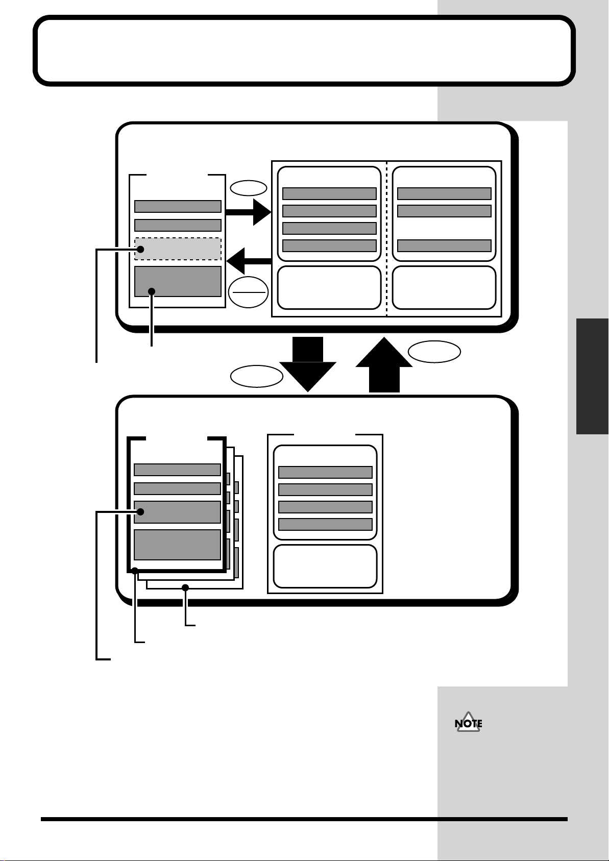
Chapter 3 Data Storage and Retrieval
Data inside this system is controlled as shown in the figure below.
fig.03-01
Internal Memory of the VM-C7200/C7100
PROJECT
(Current Settings)
SYSTEM SETTING
MIXER SETTING
SCENE
AUTO-MIX DATA
Auto-mix data is erased
after the power is turned off.
Auto-mix data is not recorded in the
console but recorded directly into project
data stored on the memory card.
Memory Card (2–16 MB)
PROJECT
(Backup)
SYSTEM SETTING
MIXER SETTING
SCENE 00-99
(only USER)
SAVE
COPY
LOAD
STORE
LIBRARY (USER)
EQ LIBRARY 00 - 99
DELAY LIBRARY 00 - 99
CH LIBRARY 00 - 99
EFFECT LIBRARY 00 - 199
EZ Routing
TEMPLATE (USER)
00 - 29
(Backup)
LIBRARY (USER)
EQ LIBRARY 00 - 99
DELAY LIBRARY 00 - 99
CH LIBRARY 00 - 99
EFFECT LIBRARY 00 - 199
LIBRARY (PRESET)
EQ LIBRARY 00 - 49
DELAY LIBRARY 00 - 19
EFFECT LIBRARY 00 - 199
EZ Routing
TEMPLATE (PRESET)
00 - 09
SELECT
Chapter 3 Data Storage
and Retrieval
AUTO-MIX DATA
EZ Routing
TEMPLATE (USER)
00 - 19
The number of storable projects differs depending on the capacity of the memory card
Current project
SCENE 00-49 when two processors are in use.
The memory of the console is classified as follows:
• Library/EZ Routing template
A library contains the settings of each input channel, equalizer, delay or effect.
Every library is named and can be reused as desired.
• Project
Combines all settings of the VM system except the library. This also includes
auto-mixing data.
(each project consumes approximately 2MB).
Even if you use an over 16
MB memory card, you
cannot save the data more
than 16 MB.
43
Page 44
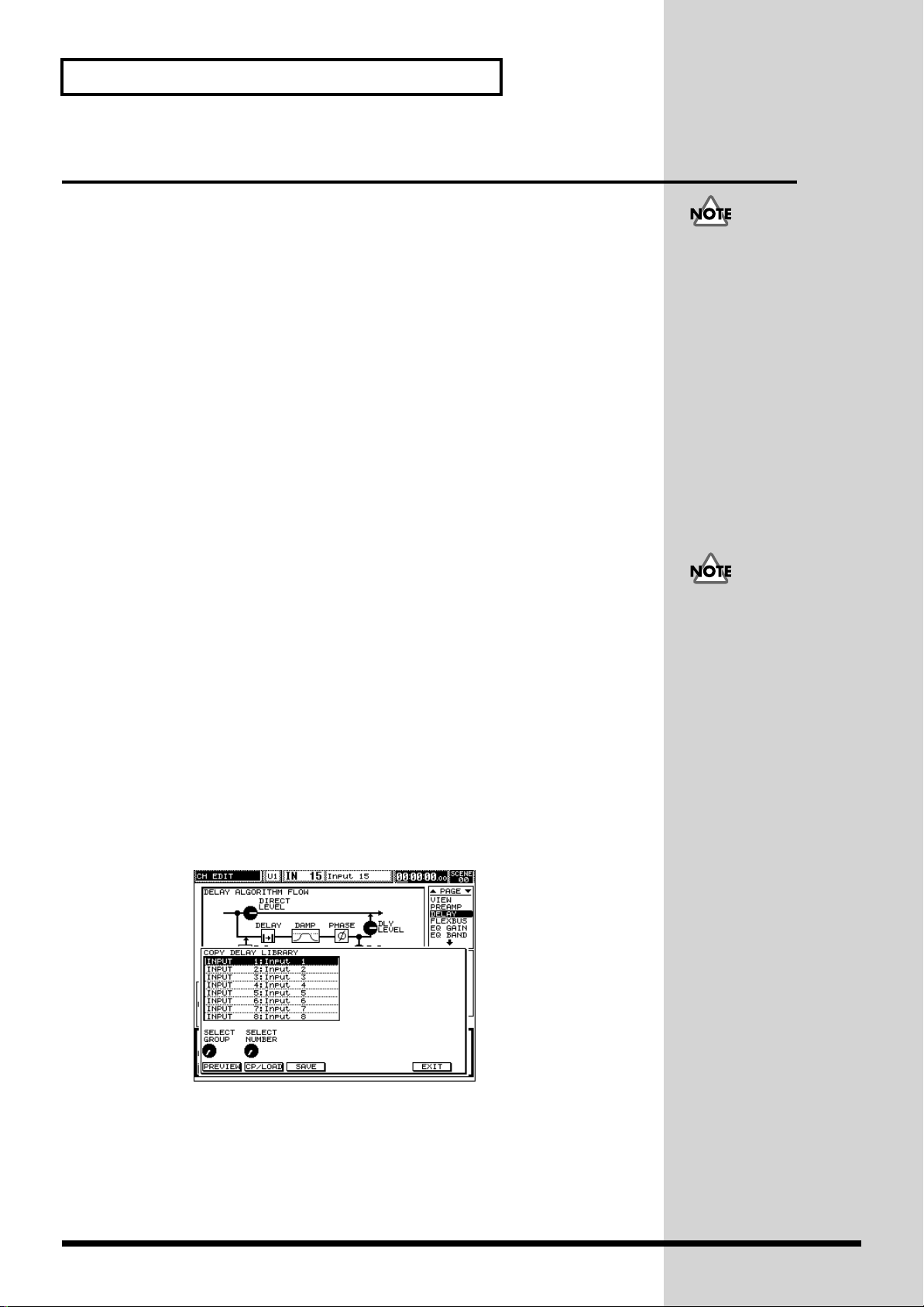
Chapter 3 Data Storage and Retrieval
Copying Libraries Containing Various Settings
Four types of libraries are available as follows:
Channel library: Combines major parameter settings of one input channel (user
library only).
Channel delay library: Combines phase delay (p. 69) and feedback delay (p. 81) of
each input channel.
Channel equalizer library: Combines the settings of the parametric equalizer
provided for each input channel.
Effect library: Combines the settings of internal effects 1 to 8 and master effect (p.
113).
■ Calling up and saving a library screen
Typically, use [COPY/LIBRARY] beneath the ten-key keypad to select a library and
copy the current settings. Press [COPY/LIBRARY] when the channel edit screen of
each item is recalled to call up the copy/library screen.
Copying a library to each channel
In the following descriptions, the delay library is used as an example. (Since Step 2
differs for the equalizer or channel library, refer to the column on next page.)
The following inputchannel information is not
included in a channel
library:
input source, channel link
parameters,
pan link parameters,
status of auto-mixing and
solo,
assignment of insert effect,
connection from input
channel to MULTI OUT,
preamplifier gain of input
channel and setting of
phantom power supply
When you copy the effect
library, use the effect
library screen (p. 113)
instead of [COPY/
LIBRARY].
1. Make sure that [INPUT] or [MULTI IN] is selected under SECTION.
2. Call up the delay channel edit screen.
While holding down [CH EDIT] of the channel whose library is to be copied or
saved, press the status button marked [PREAMP GAIN] or [DELAY].
3. Press [COPY/LIBRARY].
This opens the channel delay library screen.
fig.03-02
4. Select one of the libraries and check the effect.
First, turn the V1 knob (SELECT GROUP) to select U (“User”) or P (“Preset”). Then
turn the V2 knob (SELECT NUMBER) to select the number corresponding to the
desired library name on the display.
The actual effect can be heard by pressing [F1] (PREVIEW) (highlighted in black). To
initialize the channel delay, turn the button off.
● In this example, the
quick channel edit function
(p. 63) calls up the screen.
44
Page 45

Chapter 3 Data Storage and Retrieval
b
5. Confirm selection.
After selection, press [F2] (CP/LOAD) to copy the contents of the library to the
channel delay. After this operation, the settings cannot be returned to their state
prior to copying.
How to call up the copy/save screen for each library
The following library screens can be called up by pressing [COPY/LIBRARY] in
Steps 2 and 3 on the previous page (press a desired channel in place of [CH EDIT]):
• Channel library
Press STATUS [CH VIEW] while holding down [CH EDIT].
• Channel delay library
Press STATUS [PREAMP GAIN] while holding down [CH EDIT].
Press STATUS [DELAY] while holding down [CH EDIT].
• Channel equalizer library
Press STATUS [EQ GAIN] while holding down [CH EDIT].
Press STATUS [HPF/LO] while holding down [CH EDIT].
Press STATUS [LO-MID] while holding down [CH EDIT].
Press STATUS [HI-MID/HI] while holding down [CH EDIT].
In Step 4, INPUT or MULTI
IN can be selected instead
of U or P, and the V2 knob
can be used to select the
channel (1 to 24).
Proceeding to Step 5 (CP/
LOAD) in this state enables
the settings of the library to
e copied from the selected
channel to channel whose
[CH EDIT] is turned on.
Chapter 3 Data Storage
and Retrieval
Screen operations are the same for all libraries.
Saving the current settings into a library
In the following descriptions, the delay library is again used as an example. (Since
Step 2 differs for the equalizer or channel library, refer to the column above.)
1. Make sure that [INPUT] or [MULTI IN] is selected under SECTION.
2. Call up the delay channel edit screen.
While holding down [CH EDIT] of the channel whose library is to be copied or
saved, press the status button marked [PREAMP GAIN] or [DELAY].
3. Press [COPY/LIBRARY].
This opens the channel delay library.
fig.03-02
45
Page 46

Chapter 3 Data Storage and Retrieval
4. Select the number of the library to which you want to save the settings.
First, turn the V1 knob (SELECT GROUP) to select U (“User”). Then turn the V2 knob
(SELECT NUMBER) to select the number corresponding to the desired library name
on the display.
To audition a library before it is overwritten (or erased), press [F1] (PREVIEW)
(highlighted in black) to hear the library. To initialize the channel delay, turn the
button off.
5. After selection, press [F3] (SAVE).
This opens the screen for saving the library. You can name the library on this screen
if necessary (see the next section).
6. Press [F5] (SAVE) to save the current settings.
After a confirming message appears, press [F5] (ENTER).
The delay settings of the channel are then copied to the selected library. This erases
any existing data in the selected library
Naming a library as it is saved
While saving (see the preceding section), each library can be named using up to 12
characters – this allows is to be easily identified.
1. Open the save screen of each library (Step 3 in the previous section).
fig.03-03
(Example: a delay library)
1. Select the character position (digit).
Turn the V1 knob (CURSOR POS) to move the cursor to the desired character
position.
2. Use the following knobs to enter a character:
Upper-case alphabet (A to Z): V2 knob
Lower-case alphabet (a to z): V3 knob
Values and symbols (1, 2, 3, “!”, “#”, etc.): V4 knob
Functions of [F2] to [F4]
• [F2] (DELETE): Deletes the character at the cursor position and moves the
following characters back to fill the newly created space.
• [F3] (INSERT): Inserts a space at the cursor position and pushes the following
characters forward to make room for the new characters.
• [F4] (SPACE): Replaces the character at the cursor position with a space.
● Press [F1] (ASCII)
(highlighted in black) to
enable the entering of
characters using buttons.
With this function,
characters printed to the
left of various buttons on
the panel – CH EDIT,
STATUS, ten-key pad, etc.
– can be entered by
pressing each button.
46
Page 47

Storing a Mixing State (Scene)
A Scene is a complete set of mixer settings that can be stored at any given point
during work on a project. One hundred Scenes (numbered 00 to 99) can be stored per
project.
Many items are stored in a Scene, including level and pan settings of input and
multi-in channels, the main channel, Cue and Flex Buses, as well as equalizer and
delay settings and internal patch connections. You can specify or limit the
parameters to be recalled in a Scene (p. 48).
IMPORTANT
The Scene memory function requires the presence of a formatted memory card on
which a project has been created or selected.
Chapter 3 Data Storage and Retrieval
When the project utilizes
two mixing processors, the
number of storable Scenes
decreases to 50.
The parameters stored in a
Scene are the same as those
saved in an EZ Routing
template.
Chapter 3 Data Storage
and Retrieval
■ Storing/recalling/erasing a scene
Storing and recalling a scene
1. Press [SCENE] – the ten-key keypad begins to blink.
This indicates that the system is waiting for the first digit of a Scene number to be
entered.
2. Press one of [0] to [9] buttons on the ten-key keypad to enter the first digit.
The selected number is stored as the first digit of the Scene number, and the keypad
stops blinking.
The Scene number is indicated as “SCENE 0_” or “SCENE 3_” in the upper righthand corner of the display.
3. Press a currently unlit key on the ten-key keypad.
The button turns on, registering the state of the mixer as a Scene.
4. Press free buttons one by one to store Scenes.
* After all buttons have turned on, return to Step 2 to select a new first digit.
5. After changing the mixer settings, press a lit key on the keypad.
In approximately two seconds, the stored Scene is recalled.
Clearing a scene
With [SCENE] on:
With [SCENE] on, press a
key on the ten-key keypad
to designate the second
Scene-number digit. To
store Scene 53, for example,
press [SCENE], [5] and [3],
in that order. If [SCENE]
and [3] remain lit after this
procedure, the storing of
Scene 53 has been
successfully completed. (If
[3] is already lit after
pressing [SCENE] and [5],
however, location 53 is
already in use. In this case,
select another second
digit.)
1. Press a currently lit key on the ten-key keypad while holding down
[CLEAR].
This clears the Scene information stored at that location.
47
Page 48

Chapter 3 Data Storage and Retrieval
■ Selecting which parameters will be recalled
Hold [SHIFT] and press [SCENE] (this is the same as pressing [EDIT]) to open a
screen for detailed Scene-related settings. Every time [PAGE DOWN] is pressed,
screens change as shown below, allowing you to select the parameters to be recalled
with the Scene switching.
SCENE SELECT/ACTIVE PARAMETER page
fig.03-04
• Positioning the cursor on the upper section of the screen enables a Scene for
recalling ([F1]), clearing ([F2]) or storing ([F3]). The Scene number can be
selected while checking the name (explained below) using the V1 knob
(SELECT).
• Positioning the cursor on the lower section of the screen enables you to access
the active parameters using [F1] to [F6] (black highlight indicates that the Scene
is valid).
SCENE ACTIVE CHANNEL page
fig.03-05
48
Page 49

Chapter 3 Data Storage and Retrieval
b
fig.03-06
• Positioning the cursor on each section of the screen enables a channel whose
settings change according to the Scene selected using [F1] to [F6] (black highlight
indicates that the Scene is valid).
Chapter 3 Data Storage
and Retrieval
CURRENT SCENE NAME EDIT page
fig.03-07
• A Scene name (12 characters max.) selected from the list on the top page (SCENE
SELECT/ACTIVE PARAMETER) can be changed. The change will be reflected
in the list.
Screen operations are similar to those for naming an input channel. For details,
refer to “Naming input channels” (p. 83). The differences between them are as
follows:
• No short names (3 characters) can be used.
• The EZ naming function is not available.
• Assignments of the V1 to V6 knob functions (except common knobs).
• Functions added to [F6] (write-protect on/off).
The write-protect (on or off) state is also indicated by the letter “P”
(checked or unchecked) in the list on the top page of this operation (SCENE
SELECT/ACTIVE PARAMETER).
When [F6] (PROTECT) is
highlighted in black on the
display, the Scene whose
name is being changed is
erase-protected, thus
preventing the Scene from
eing cleared. When [F6]
(PROTECT) is turned off,
clearing is enabled.
When a project is erased
from a memory card, the
Scenes contained within it
are also erased, even if
they’re erase-protected.
49
Page 50

Chapter 3 Data Storage and Retrieval
Storing and Recalling All Mixer Settings (Project)
A memory card may be able to hold more than one project.
IMPORTANT... Please read the following notices:
• In order to successfully save a project on a card, the following steps are required
before starting a new operation. Otherwise, a project cannot be stored.
1. Prepare a formatted memory card (p. 51).
2a.Create a new project on the card (p. 52).
Or,
2b.Select a project on the card whose contents are to be changed (p. 52).
• Since projects are updated by overwriting them, your current settings cannot be
stored in more than one project. To store several states of a project, use the
Scene-memory function (p. 47).
• Once the project-storing operation has started, do not select another project
without completing the storage procedure. After a project is selected (p. 55), the
current project is changed to the new one and the old project’s current settings
are will be lost.
About the write protect function of the memory card
The Write Protect function protects data stored on the memory card from accidental
erasure. You should affix a supplied Write Protect Sticker onto the Write Protect
Area whenever you do not intend to write data on the memory card.
fig.3-0001
Write
Protect Area
The number of storable
projects differs depending
on the card used. For
example, only one project
can be stored on a 2 MB
card.
A memory card to use with
this system is SmartMedia
used for the digital camera
as well and so on.
* When affixing the sticker, make sure that it is properly positioned over the Write
Protect Area.
* Affix it securely, so it will not come off. Should they come loose inside the slot,
the card could get stuck.
* Do not use any stickers other than the supplied ones.
* If the sticker is dirty, the Write Protect function may not work properly. When
the sticker gets dirty, clean it with a soft dry cloth.
50
Page 51

Chapter 3 Data Storage and Retrieval
b
■ Preparing a memory card for project storage
Before using a new memory card or one that has been used for another purpose, be
sure to format it.
Formatting a memory card
1.
Hold [SHIFT] and press [PROJECT] – this is the same as pressing [SYSTEM].
After the menu appears, press CURSOR [DOWN] to display the following screen.
fig.03-08
2. Press [F6] (MEMORY CARD) and [F2] (FORMAT), in that order.
fig.03-09
After formatting, all data
on the card is erased.
If you press [F6]
(MEMORY CARD), [F3]
starts functioning as the
“SCAN” button. You can
update a project list on the
screen by inserting another
card and pressing this
utton when the screen is
open.
Chapter 3 Data Storage
and Retrieval
3. Press [F5] (OK) by following the displayed directions.
4. After the confirmation message appears, press [F5] again.
Formatting starts. After it is completed, press [F6] (EXIT).
In order to store a project on a formatted memory card, a new project must be created
on the card before starting the storage operation.
The numbers (00, 01, 02,
etc.) listed after formatting
show you the number of
projects the card can hold.
51
Page 52

Chapter 3 Data Storage and Retrieval
b
Creating a new project
1. Press [PROJECT].
After a menu appears, press CURSOR [DOWN] to display the following screen.
fig.03-10
2. Press [F2] (NEW).
fig.03-11
3. Press [F2] (CREATE) and then [F5] (OK).
After the creation process is completed, press [F6] (EXIT).
■ Storing a project
The current state of the console can be stored at any time by overwriting and
updating the new project already created on a card.
Updating (storing) a project
1. Press [PROJECT].
After a menu appears, press CURSOR [DOWN] to display the following screen.
fig.03-10
Pressing [UNDO/REDO]
eneath the ten-key keypad
while holding down
2. Press [F1] (STORE) and then [F2] (STORE).
3. Press [F5] (OK) and then [F6] (EXIT) after storing is completed.
[SHIFT] allows you to
proceed to Step 3 from any
screen.
52
Page 53

■ Re-naming/erase-protecting a project
b
A project can be re-named using up to 12 characters as follows:
• Name the current project on the project-naming screen.
• When a memory card is used, store the same project on the card to overwrite
and update it.
Naming and adding comments to a project
1. Press [PROJECT] and CURSOR [DOWN], in that order.
2. Press [F3] (NAME/PROTECT).
The project-naming screen appears.
fig.03-12
The following operation is similar to naming an input channel. For details, refer to
“Naming input channels” (p. 83). The differences between them are as follows:
• A comment (32 characters) can be attached instead of a short name (3
characters).
• The EZ naming function is not available.
• Assignments of the V1 to V6 knob functions (the contents are the same).
• Functions added to [F6] (write-protect on/off).
Chapter 3 Data Storage and Retrieval
On this screen, comments
of up to 32 characters can
e added to a project,
allowing you to store
relevant notes within the
project. This screen also
allows you to store a
project with PROTECT
activated, thus prohibiting
the project from being
inadvertently overwritten
or erased accidentally.
Chapter 3 Data Storage
and Retrieval
Erase-protecting a project
A project selected on a memory card can be protected from erasure (p. 56). This also
prohibits the accidental overwriting/updating of the project.
When more than one project exists on a card, only the currently selected project is
protected.
Erase-protecting a project
From the project-naming screen:
Formatting (p. 51) can be
performed even if a
protected project exists on a
memory card. After
formatting, all data on the
memory card is erased.
1. Press [PROJECT], CURSOR [DOWN] and [F3] (NAME/PROTECT), in this
sequence.
2. Turn [F6] (PROTECT) on to highlight it in black.
3. Open the storing screen.
Press [UNDO/REDO] (STORE) under the ten-key keypad while holding down
[SHIFT].
fig.03-13
4. Press [F6] (OK) to store the project.
After storing is completed, press [F6] (EXIT) on the screen.
Resetting project erase-protection
To reset card protection, follow the above operations in “Erase-protecting a project,”
53
Page 54

Chapter 3 Data Storage and Retrieval
but turn [F6] (PROTECT) off so that it’s not highlighted in Step 2.
54
Page 55

Chapter 3 Data Storage and Retrieval
■ Selecting a project
More than one project may be stored on a memory card, allowing you to store
completely different console settings for each project. Select and switch projects by
following the procedure below.
After a project is selected, the console settings are replaced with that of the selected
project, removing the prior settings. Before switching to a new project, make sure to
store the current project on the card if you wish to retain it.
Selecting a project
1. Press [PROJECT], CURSOR [UP] and [F1] (SELECT), in that order.
This calls up the project select screen.
2. Select a project using the V1 knob (SELECT NUMBER).
3. Press [F2] (SELECT).
4. Press [F5] (OK) and then [F6] (EXIT) after selection is completed.
The following information can be referred to on the
project list.
fig.03-14
NAME: Project name (12 characters max. See p. 53.)
UPDATE: Date of update (according to internal clock at time of storing)
T: Type (number of consoles used by the project, 1 or 2)
P: Protect (protected from accidental erasure when the letter is checked.
See p. 53.)
“T” is automatically determined by the number of consoles connected when the
project is created. For a Type 2 project, the number of storable Scenes decreases by
half (50).
Chapter 3 Data Storage
and Retrieval
55
Page 56

Chapter 3 Data Storage and Retrieval
b
■ Copying a project
A copy of a project can be created on the same card that contains the original. This is
useful when you want to start mixing from default console settings of your own
design. Since the currently selected project will be overwritten when a storage
operation is performed, it’s recommended that you create a copy of the default
project on the card and select the copy to ensure that you don’t accidentally
overwrite the original.
Copying a project
1. Select a the project you want to copy.
Refer to “Selecting a project” above.
2. Press [PROJECT], CURSOR [DOWN] and [F4] (COPY), in that order.
This calls up the project-copy screen.
3. Select a project number as a destination for your new copy using the V1
knob (SELECT NUMBER).
4. Press [F2] (COPY) and [F5] (OK).
After a message appears, press [F5] (OK) again.
5. After copying is completed, press [F6] (EXIT).
■ Erasing a project from a memory card
Since the number of projects storable on one card is limited (8 max. on a 16MB card),
existing projects can be erased as necessary.
Erasing a project
1. Press [PROJECT], CURSOR [UP] and [F2] (ERASE), in this sequence.
This calls the project-erase screen.
2. Select a project using the V1 knob (SELECT NUMBER).
3. Press [F2] (ERASE).
4. Press [F5] (OK) and then [F6] (EXIT) after erasure is complete.
A confirmation message
appears if you attempt to
overwrite existing data to
ensure that this is really
what you intend to do.
The number of processors
available for an existing
project – Type 1 or 2, as
indicated on the list –
however, it cannot be
changed. To change a
project’s type, turn off the
power. Then turn on the
power again and restore
the project.
The current project cannot
e erased.
56
Page 57

Chapter 3 Data Storage and Retrieval
b
Copying Data to/from a Memory Card
In this system, the project currently selected on a memory card is designed to reflect
the project on the console. This means that a memory card should always be installed
and should be considered a part of the console’s internal memory that can be
removed and transported to another system.
For this purpose, one memory card is attached to the console (both VM-C7200 and
C7100) at the time of purchase.
The method for storing a project on a card is explained in detail in this chapter. The
procedure is important and it is recommended that you review it – see p. 52.
To use the Scene function, a
memory card – which has
een formatted (p. 51) and
on which a project has been
created– must be installed.
Since auto-mix settings are
saved when a project is
stored, a card must be
prepared and a new project
created before starting
console operation.
■ Moving and returning a set of libraries in a console to
and from a memory card
A memory card can not only store projects, but also back up libraries and EZ Routing
templates of a console’s channels and effects.
Copying a set of libraries from/to a card
From the SYSTEM menu:
1. Hold [SHIFT] and press [PROJECT] (same as pressing [SYSTEM]).
2. Open the LIBRARY page on the memory card.
Press CURSOR [DOWN], [F6] (MEMORY CARD) and [PAGE DOWN], in that
order.
fig.03-15
“A set of libraries” above
includes EZ Routing
templates as well.
When a set of libraries
stored on a card is loaded
into the console, it replaces
the current user libraries in
the console. Only one set of
user libraries can be stored
on a memory card. This
means that two or more
memory cards are required
for backing-up multiple
user libraries.
Chapter 3 Data Storage
and Retrieval
3. Determine what you wish to transfer to/from the card.
Select [LOAD/SAVE TARGET] – LIBRARY or TEMPLATE – on the upper section
using
CURSOR [UP] or [DOWN] and turn [F2] to [F5] on (highlighted in black) or
off. Only the items that are turned on will be saved, loaded, or exchanged.
4. Select [COMMAND] using CURSOR [DOWN].
5. Perform the function.
Select and press either [F5] (LOAD) or [F6] (SAVE). After the confirmation screen
appears, press [F5] (OK) to perform the selected function.
“Loading” of library data
means copying it from the
card to the console,
overwriting the console’s
current library. “Saving”
refers to overwriting data
from the console to the
card.
57
Page 58
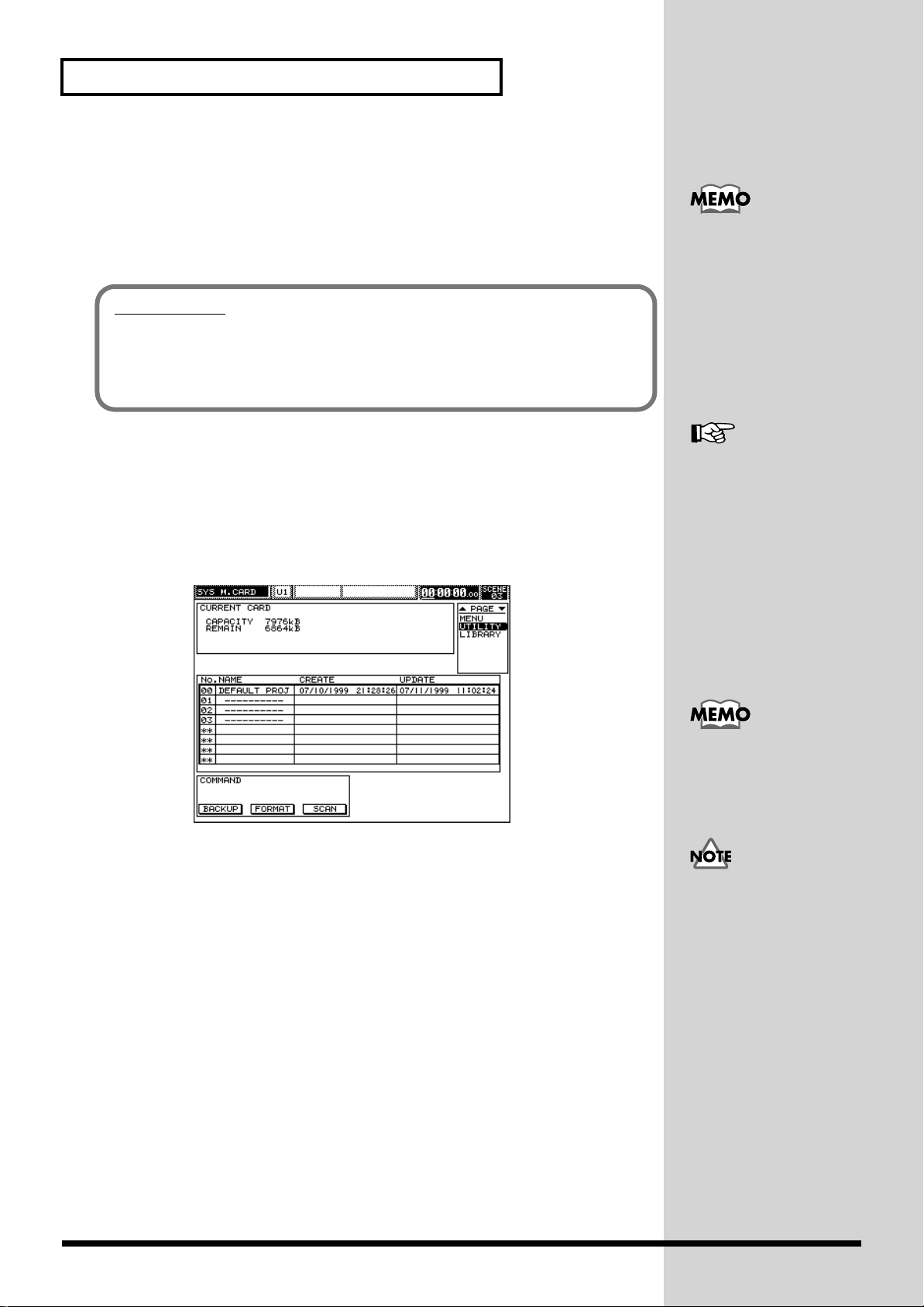
Chapter 3 Data Storage and Retrieval
b
b
■ Backing up a memory card
A memory card can be backed up using following procedure.
For backing up, a formatted (p. 51) memory card for copying to (the destination card)
must be prepared in addition to the memory card to be copied from (the source
card).
IMPORTANT
The console’s auto-mixing memory is used during the memory-card backing-up
process. Therefore, all auto-mixing information which is currently held in the
console’s memory is erased during the back-up process. For this reason, be sure to
save the current project before you begin the back-up procedure.
Prepare a destination card
of at least the same capacity
as the source card. If the
capacity of the destination
card is smaller than that of
the source, backing up may
e halted before all of the
source card’s data can be
copied.
Backing up a memory card
1. Open the SYSTEM menu.
Hold [SHIFT] and press [PROJECT] (same as pressing [SYSTEM]).
2. Open the UTILITY page on the memory card.
Press CURSOR [DOWN] and [F6] (MEMORY CARD), in that order.
fig.03-16
3. Press [F1] (BACKUP).
After a message requesting the source card appears, make sure that the source card
has been inserted, and then press [F5] (OK). The back-up procedure will begin.
4. After a message requesting the destination card appears, remove the source
card, insert the destination card and press [F5] (OK). Data writing starts.
After writing is completed, return to Step 3 and repeat the above
procedure. Backing up is finished when the “Completed” message appears.
Format (p. 51)
The number of repetitions
of Steps 3 and 4 will differ
depending on the amount
of data to be backed up.
To cancel the process, press
[F6] (CANCEL). Once
acking up has begun, data
previously stored on the
destination card cannot be
restored even if the backup process is cancelled.
58
Page 59
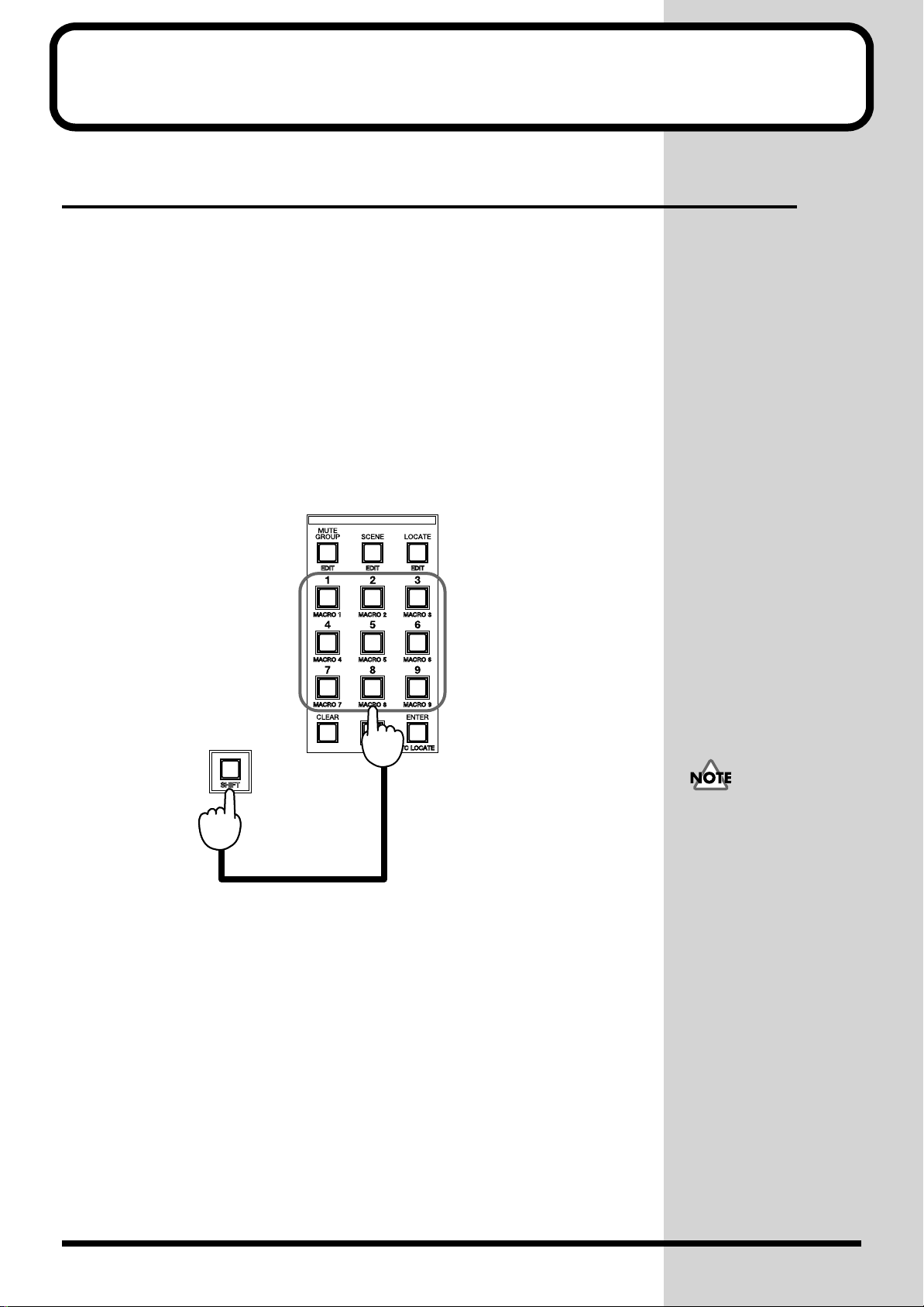
Chapter 4 Useful Functions
b
Storing Frequently Used Screens (Macro Function)
When switching back and forth between screens to compare and adjust settings
(when editing effect algorithms, for example), various steps must be performed over
and over. In this case, any of the screens can be stored as a “macro” so that you can
jump to the screen simply by pressing a single button. Since the screen and the
current cursor position are both stored in a macro, there’s no need to move the cursor
button after recalling it.
■ Storing a screen as a macro
1. Call-up the desired screen.
Move the cursor to a frequently used parameter.
2. Press one of the macro buttons – [MACRO 1] to [MACRO 9] – while
holding down [SHIFT].
The LED of the selected button lights to show that a macro has been stored there.
fig.04-01
You cannot overwrite a
utton which a macro has
already been registered. In
this case, clear the macro
and register a new one.
■ Recalling a screen (macro)
1. Press one of [MACRO 1] to [MACRO 9] while holding down [SHIFT].
The screen stored in the macro appears.
■ Clearing a stored macro
1. While holding down [SHIFT] and [CLEAR], press one of [MACRO 1] to
[MACRO 9].
The indicator of the button of which a macro has been cleared goes out.
58
Page 60

Chapter 4 Useful Functions
b
Calling Up Stored Connections (EZ Routing)
The EZ Routing function allows you to quickly establish a set of saved connections.
EZ Routing can be a connection template or a virtual patchbay setup.
■ Routing template
This type of EZ Routing instantaneously calls up one of the pre-defined internal
connection templates, each of which is designed to serve a particular purpose. When
shipped, 9 EZ Routing template presets are stored in the console. The console can
also store up to 30 user-defined EZ Routing templates. The data saved in a template
is the same as that saved in a Scene on a memory card.
Selecting a template
1. Press [EZ ROUTING] and [F1] (TEMPLATE), in that order.
This calls up the template select/save screen.
2. Select the desired template.
Turn the V1 knob (SELECT GROUP) to select P (“Preset”) or U (“User”). Then turn
the V2 knob (SELECT NUMBER) to select a number – P000 to P009 or U000 to U029
– corresponding to the desired template’s name.
3. Press [F2] (COPY).
This activates the template’s settings, changing the current settings.
Press [F1] (PREVIEW) so
that it’s highlighted in
lack to temporarily
change the internal
connections to those in the
selected template; this
allows you to preview the
new connections. Turn [F1]
off to restore the current
settings.
The original connections
cannot be restored after this
step, unless they are saved
as a template or Scene.
Chapter 4 Useful Functions
59
Page 61

Chapter 4 Useful Functions
b
Saving the current connections as a
template
1. Press [EZ ROUTING] and [F1] (TEMPLATE), in that order.
This calls up the template select/save screen.
2. Select a user template location in which to save the current connections.
Turn the V1 knob (SELECT GROUP) to select U (“User”). Then turn the V2 knob
(SELECT NUMBER) to select a number (000 to 029) corresponding to the desired
template name on the display.
3. Save the template.
After selecting the template location to which you’ll be saving the current settings,
press [F3] (SAVE) and then [F5] (ENTER) to execute the procedure. The location’s
previously saved settings are overwritten and cannot be recalled.
fig.04-03
Press [F1] (PREVIEW) so
that it’s highlighted in
lack to temporarily
preview the selected
template’s internal
connections. Turn [F1] off
to restore the current
settings you wish to save.
To cancel saving, press [F6]
(EXIT) in Step 3.
■ Virtual patchbay
The virtual patchbay allows you to make connections between input jacks and
assignable output jacks by connecting virtual cables between them on the display.
Since the virtual patchbay also allows you to establish the routing of signals from RBUS and multi-in channels, the correspondence between the digitally connected
multi-track recorder tracks (up to 24, 8 tracks x three recorders) and multi-in
channels 1 to 24 can be set up as your needs dictate.
Changing connections using the virtual patchbay
1. Press [EZ ROUTING] to call up the menu screen.
2. Press [F2] (PATCHBAY).
This calls up the input channel patchbay screen.
3. Select the connection to set.
Select input channels or output terminals in six pairs using CURSOR [UP], [DOWN],
[LEFT] or [RIGHT].
4. Set the desired connection.
Turn the V1 to V6 knobs to change the patchbay connection.
R-BUS (p. 243)
60
Page 62
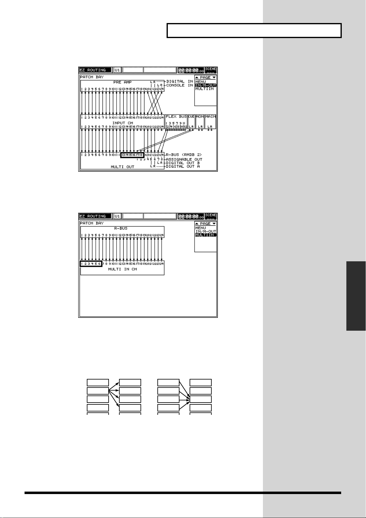
ig.04-04
fig.04-05
Chapter 4 Useful Functions
Press [PAGE DOWN] to call the multi-in channel patchbay screen. On this screen,
the assignments from multi-in inputs (each input to R-BUS) to multi-in channels can
be changed.
fig.04-06e
* For internal connections using the virtual patchbay, signals can also be assigned
to several destinations. Multiple signals, however, cannot be simultaneously
assigned to a single destination.
Possible
IN 1 OUT 1
IN 2 OUT 2
IN 3 OUT 3
IN 4 OUT 4
Impossible
IN 1 OUT 1
IN 2 OUT 2
IN 3 OUT 3
IN 4 OUT 4
Chapter 4 Useful Functions
61
Page 63
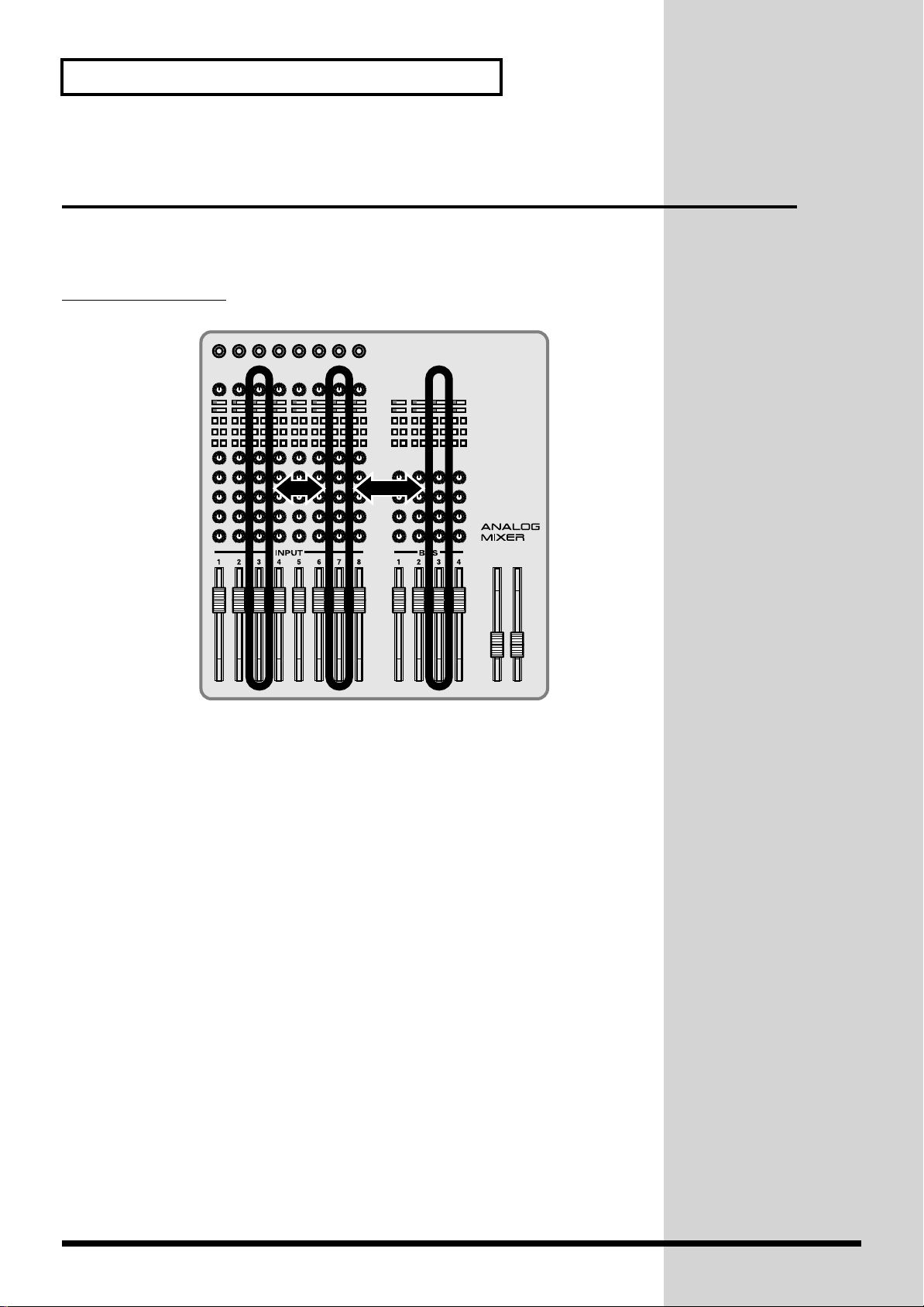
Chapter 4 Useful Functions
Directly Calling Up a Screen for Each Channel (Quick Channel Edit)
“Channel edit” (CH EDIT) refers to the displaying of each input (1–24), multi-in or
Flex Bus channel’s parameters on the screen and the changing of their settings. It
allows you to focus your attention on a single channel.
CH EDIT operation
fig.04-07
Select a channel – one of the C7200’s 24 vertical columns, or one of the C7100’s 12 –
and control the parameters for it using the V1 to V6 knobs or [F1] to [F6].
1. Press [CH EDIT] of the desired channel to change any of its settings.
This calls one of the channel’s parameter screens.
2. Press [PAGE UP] or [PAGE DOWN] to call up the desired parameter’s
screen.
3. Press the cursor button to move the cursor to the target parameter set.
4. Set a value by turning the V1 to V6 knob or pressing [F1] to [F6].
62
Page 64

■ Directly jumping to a parameter’s screen
(Quick channel edit)
Using [PAGE UP] or [PAGE DOWN] to move through numerous parameter screens
in order to reach a desired parameter’s screen can be time-consuming. To save time,
you can jump directly to certain parameters using the status buttons of channels 13
to 24. While holding down [CH EDIT] on the channel you’re working with, press one
of the status buttons to display the desired parameter screen.
fig.04-08
Channel Parameter setting screen
13 (1) Preamplifier-related setting
14 (2) Delay-related setting
15 (3) EQ (gain)-related setting
16 (4) EQ (low-range, high-pass filter)-related setting
17 (5) EQ (mid-range)-related setting
18 (6) EQ (high-range)-related setting
19 (7) Setting of signals to be sent to Flex Buses 1 to 6
20 (8) Setting of signals to be sent to Flex Buses 7 to 12
21 (9) MULTI OUT-related setting
22 (10) Surround depth-related setting
23 (10) Setting of signals to be sent to main/Cue buses
24 (12) General channel parameter list screen
Chapter 4 Useful Functions
Chapter 4 Useful Functions
* A bracketed channel number indicates that the VM-C7100 console is used.
Example: [CH EDIT] + [CH VIEW]
fig.04-ChView
The CH EDIT VIEW screen
allows you to set all the
channel parameters
including the transmission
level to the respective
output channels, pre-amp,
and feedback delay
simultaneously.
63
Page 65

Chapter 4 Useful Functions
Simultaneously Setting Several Channels’ Parameters (Parameter View on Fader)
When parameters such as levels, pans and the amount of signal sent to the Flex Buses
are to be set, these parameters’ values for all channels can be displayed at the same
time. This display is called the “parameter view on fader.” This view is helpful when
the parameter settings of multiple channels need to be adjusted at the same time.
Operation of [PARAM VIEW on Fader]
fig.04-09
Allows you to view parameter settings for all channels simultaneously, controlling
their value primarily by using the console’s channel faders.
Determining a parameter setting to change
Press any of the numbered buttons under [PARM VIEW on Fader] to view its
corresponding parameter in the currently selected parameter section. Since the types
of parameters differ in each section, the screen may not change when a numbered
button is pressed.
fig.04-10e
Parameter Setting under PARAM VIEW on Fader
SECTION
(Signal Line)
INPUT YES
MULTI IN
FADER GROUP
FLEX BUS 1–12
MIDI
MULTI OUT
[OTHER PARAMETERS A]/[OTHER PARAMETERS B]
Sets the equalizer or delay.
To select a parameter, move the cursor to the bottom of the screen, turn the [V1] knob
to select the target parameter and press [F1] (SET).
CH
LEV
YES
YES
YES
YES
YES --- --- --- --- --- ---
CH
PAN
YES
YES
--YES
YES
CUE
LEV
YES
YES
---
YES
---
CUE
PAN
YES
YES
---
YES
---
PREAMP
GAIN
YES
---
---
---
---
SURROUND
DEPTH
YES
YES
---
YES
---
FLEX BUS
send to 1–12
YES
YES
---
YES
---
OTHER
PARAMETERS
YES
YES
--YES
YES
---
64
Page 66

[FLEX BUS 1 to 6]/[FLEX BUS 7 to 12]
b
Sets signals to be sent to Flex Buses 1 to 12.
• PAN: Fixed sound position
• LEVEL
• BUS SEND: Activates/de-activates sending of signal to a Flex Bus.
Chapter 4 Useful Functions
Pan control is inactive
when no Flex Buses are
linked. To learn about Flex
Bus linking, refer to p. 102.
[PREAMP GAIN]
Sets the preamplifier.
• GAIN: Analog preamplifier gain
• PHANTOM: Supplies/does not supply phantom power to the microphone.
[CH PAN]/[CH LEVEL]
Sets signals to be sent to the main stereo bus.
• PAN: Fixed sound position
• LEVEL
• MAIN SEND: Sends/does not send signals to the main stereo bus.
[SURROUND DEPTH]
Sets surround depth.
• PAN: Direction of sound (right/left)
• DEPTH: Direction of sound (up/down)
• MAIN SEND: Sends/does not send signals to the main channel.
[CUE PAN]/[CUE LEVEL]
Sets signals to be sent to the Cue bus.
• PAN: Fixed sound position
• LEVEL
• CUE SEND: Sends/does not send signals to the Cue bus.
When Flex Buses are
linked, changing the
parameter setting of one
also changes the parameter
setting of the other.
The same screen appears
after either [CH PAN] or
[CH LEVEL] is pressed.
After [CH PAN] is pressed,
however, the pan value can
e set using a fader.
Chapter 4 Useful Functions
The same screen appears
after either [CUE PAN] or
[CUE LEVEL] is pressed.
After [CUE PAN] is
pressed, however, the Cue
pan can be set using a
fader.
65
Page 67

Chapter 4 Useful Functions
How to set parameters
fig.04-11e
[V1]–[V6] knobs
Fader / [V1]–[V6] knobs
[F1]–[F6]
In most cases, the cursor is moved to the desired parameter and the [V1] to [V6]
knobs are used to change the setting of the selected parameter. In addition to this,
parameters can be set using faders in the “parameter view on fader” screens so that
several channels’ parameters can be adjusted at the same time. To set switches such
as BUS SEND and MAIN SEND, the cursor is moved to the target parameter and [F1]
to [F6] is pressed.
Separating screen from fader state
When screens are switched, the fader settings typically change as well. When
simultaneously adjusting the levels of both analog and digital signals received via
the R-BUS, screens may need to be switched repeatedly, since both screens cannot be
displayed at the same time. To solve this problem, turn [on Display] on to separate
the screen state from the fader state. This allows the state of screens to be switched
with the state of the faders when [on Display] is turned on. This also allows you to
adjust the analog input levels using the [V1] to [V6] knobs on the screen, and the
digital input levels using the fader.
The fader states of MULTI
IN and INPUT can be
flipped using [FLIP] (only
when the VM-C7200
console is used).
66
Page 68

Chapter 5 Mixing Procedure 1 (Input Channel)
b
There are two different types of channels for bringing audio into the system:
• INPUT channels handle standard microphone, line and digital audio signals.
• MULTI IN channels handle audio from digital multi-track devices connected to
an optional R-BUS connector. The VM-24E I/O Expansion board, purchased
separately, adds 24 channels of digital R-BUS inputs and outputs to your
system.
Press [INPUT] or [MULTI IN] to select the type of inputs you want to edit. The
general editing procedure and channel setup screen is similar for both types of input.
Basic Settings by Input Channel
To set up an input channel, press the channel’s [CH EDIT]. When you press a
channel’s [CH EDIT], its setup screen is displayed.
■ Selecting an input channel’s signal source
You can select the source of an input channel’s signal from a range of appropriate
options.
Selecting a channel’s input source
1. Press [INPUT] or [MULTI IN] in the SECTION area to select the type of
channel you want to set up.
2. Press the desired channel’s [CH EDIT].
3. Press [PAGE UP]/[PAGE DOWN] to display the channel’s PREAMP page.
fig.05-01
4. You can select the desired source by turning the V1 (SOURCE SELECT)
knob.
For input channels, you can select:
• MIC or LINE INPUTs 1 to 20 on a VM-7200 processor, or INPUTs 1 to 10 on a
VM-7100 processor.
• DIGITAL A/B. To choose DIGITAL IN A or DIGITAL IN B, follow the
procedure on p. 32.
• CONSOLE INPUT, L or R. These are the input jacks on the rear of the console.
● You can jump directly to
this screen by pressing the
PREAMP GAIN STATUS
utton while holding down
the channel’s [CH EDIT].
Chapter 5 Mixing Procedure 1
(Input Channel)
For multi-in channels, you can select:
• R-BUS inputs 1 to 24. These choices become available only with an installed VM24E, purchased separately.
67
Page 69

Chapter 5 Mixing Procedure 1 (Input Channel)
b
b
■ Gain, Phantom Power Supply, Phase and Attenuator
Various settings are available for the analog pre-amplifier at each channel’s input
section. These include:
• Gain (not available when DIGITAL A/B is selected as the input source)
• Phantom power supply (not available when DIGITAL A/B is selected as the
input source)
• Phase inversion
• Digital attenuation level
Setting up an input channel’s analog pre-amplifier
1. Press [INPUT] in the SECTION area.
2. Press [CH EDIT] for the desired channel.
3. Select the PREAMP page using the PAGE UP/PAGE DOWN buttons.
fig.05-01
Phase (p. 242)
Phantom power (p. 242)
Attenuator (p. 232)
● You can jump directly to
this screen by pressing the
PREAMP GAIN STATUS
utton while holding down
the channel’s [CH EDIT].
4. Adjust the settings as desired.
GAIN: Turn the V2 (GAIN) knob to match the pre-amp’s input gain to
the output level of the connected microphone or other audioproducing device. (+4 to -64 dB)
PHASE: Press [F3] to switch the phase inversion function on or off, as
desired. When phase inversion is active, the PHASE parameter
is highlighted on the display.
PHANTOM
POWER SUPPLY: Press F2 (48V) to switch between on (highlighted) and off. A
channel’s phantom power supply should only be turned on
when the channel is handling a signal from a device that
requires phantom power.
ATTENUATOR: Turn the V3 (ATT) knob to set the input attenuation level, from
+6 to -24 dB. Attenuation is the lowering of a signal’s level.
Start by setting the attenuator to “0 dB,” for no attenuation. If
distortion occurs as you boost frequencies in the signal during
equalization, adjust the ATTENUATOR setting to reduce the
signal’s level until the distortion is eliminated.
You can also access these parameters by pressing [CH VIEW] with [CH EDIT] (p. 63).
Setting preamp gain and phantom power in PARAM VIEW on Fader mode
1. Press [PREAMP GAIN] in the PARAM VIEW on Fader area.
2. Set each channel’s preamp gain using its fader. You can also set the preamp
gain for six channels at a time using the cursor and the V1 to V6 knobs.
There are a couple of
reasons you might want to
invert the phase of a
channel’s signal. You might
want to do this when the
signals from two
microphones used on the
same instrument are
canceling each other out—
in such a case, you’ll want
to invert the phase of one of
the signals. You may also
want to correct the phase of
a signal that has already
een phase-inverted due to
an error in cabling.
3. Cursor to the desired channel and activate or de-activate its phantom
power using [F1] to [F6]. When a channel’s phantom power is turned on,
the parameter is highlighted.
68
Page 70

Chapter 5 Mixing Procedure 1 (Input Channel)
b
■ Correcting a signal’s time delay (PHASE DELAY)
A channel’s input can be delayed to correct phasing problems between the its signal
and the signals of other channels.
When you use more than one microphone on an instrument (or other sound source),
there may be a difference in the amount of time it takes for the sound to reach each
microphone—it takes roughly 3 ms (milliseconds) for sound to travel the distance of
a meter from an instrument to a microphone. When you mix the signals from the
microphones, you may experience the loss of various frequencies in the resulting
signal due to phase differences between the microphones. You can fix such problems
by delaying the signals from those microphones placed closer to the instrument so
that they match the delay in signals from microphones placed further away.
Setting up a channel’s PHASE DELAY
1. Press and select [INPUT] or [MULTI IN] in the SECTION area to select the
type of input you want to set up.
2. Press [CH EDIT] for the desired channel.
3. Select the PREAMP page using [PAGE UP]/[PAGE DOWN].
● When the PHASE
DELAY feature is used, the
original, un-delayed sound
is not heard—only the
delayed signal is used.
● You can jump directly to
this screen by pressing the
PREAMP GAIN STATUS
utton while holding down
the channel’s [CH EDIT].
fig.05-01
4. Turn PHASE DELAY on to activate an input delay. Press [F4] (ON). When
PHASE DELAY is turned on, the parameter is highlighted.
Set the desired delay using the V4 knob. PHASE DELAY is measured in samples, the
smallest unit of time in the system. When the current sample rate is:
• 48 kHz, one sample equals about 0.021 ms.
• 44.1 kHz, one sample equals about 0.023 ms.
Chapter 5 Mixing Procedure 1
(Input Channel)
Sample rate (p. 244)
* The PHASE DELAY parameter works in conjunction with the FEEDBACK
DELAY parameter, which also allows you to delay a channel’s signal. Together,
their delay times cannot exceed 14,400 samples in total.
The current setting is displayed as a DISTANCE in meters from the sound source.
The setting is also displayed in TIME as milliseconds based on the current sample
rate.
DISTANCE is calculated on
a basis of the travel velocity
of sound at one normal
atmosphere and 20 degrees
Centigrade. You can turn
[V4] while holding down
[SHIFT] to move quickly
through the full range of
delay values. You can also
access the PHASE DELAY
parameter by pressing [CH
VIEW] with the channel’s
[CH EDIT] (p. 63).
69
Page 71

Chapter 5 Mixing Procedure 1 (Input Channel)
Setting up ON/OFF, SEND LEVEL and PAN for a Channel
Signals can be sent from each channel to the main stereo mix or to the cue bus. You
can view the SEND LEVEL and PAN settings for all channels at the same time and
use the faders or the V1 to V6 knobs to adjust them. Signals sent from channels to
Flex Buses can be set in the same manner.
To view and change the ON/OFF, SEND LEVEL and PAN values of multiple
channels at the same time, use PARAM VIEW on Fader. To set a channel’s SEND
LEVEL or PAN to the main mix, for example, follow these steps:
1. Press [INPUT] or [MULTI IN] in the SECTION area to select the type of
input you want to set up.
2. Press the [CH LEVEL] (or [CH PAN]) in the PARAM VIEW on Fader area.
3. Use each channel’s fader to set the SEND LEVEL (or PAN) of the channel’s
signal being sent to the main stereo mix.
Other buttons—pressed together with [SHIFT] in some cases—in the PARAM VIEW
on Fader area select and display different channel parameters that you can adjust
using the faders.
If you prefer, you can use CHANNEL EDIT mode to display and adjust multiple
parameters for a single channel, including send ON/OFF, SEND LEVEL, PAN and
other parameters.
The following section describes how to set a channel’s parameters using CHANNEL
EDIT mode.
See p. 64 to learn more
about PARAM VIEW on
Fader.
PAN (p. 241)
■ SEND LEVEL and PAN to the main mix and the cue
bus.
Setting a channel’s SEND LEVEL and PAN in CHANNEL EDIT mode:
1. Press [INPUT] or [MULTI IN] in the SECTION area to select the type of
input you want to set up.
2. Press the desired channel’s [CH EDIT].
3. Select the MAIN/CUE page using [PAGE UP]/[PAGE DOWN].
fig.05-02
● You can jump directly to
this screen by pressing the
MAIN/CUE status button
while holding down the
channel’s [CH EDIT].
4. If the screen you see is not the same as shown in the figure above, scroll to
the screen shown above using the UP/DOWN buttons.
70
Page 72

Chapter 5 Mixing Procedure 1 (Input Channel)
5. Set the channel’s SEND LEVEL and PAN to the main mix by adjusting:
• SEND LEVEL using the V1 (MAIN LEVEL) knob. SEND LEVEL can be set
anywhere from -∞ to +6 dB.
• PAN using the V2 (MAIN PAN) knob. PAN can be set from L63 (far left) to R63
(far right).
While in CHANNEL EDIT mode, you can also set two other parameters that affect
sending the channel’s signal to the main mix:
• SEND ON/OFF—This sets whether or not the channel’s signal is sent to the
main mix. Press [F1] (ON)—when the channel’s signal is being sent to the main
mix, the parameter is highlighted.
• PAN LINK—Adjacent channels can be stereo-linked in odd/even pairs—
Channels 1 and 2, Channel 3 and 4, Channels 5 and 6, and so on. When channels
are pan-linked, they’re locked together at their current pan positions into a single
stereo image. If you lower or raise either channel’s PAN setting, the entire stereo
image will be shifted left or right accordingly. To pan-link two channels, press F2
(PANLINK). When PAN LINK is active, the parameter will be highlighted.
6. Set the channel’s SEND LEVEL and PAN to the cue bus by adjusting:
• SEND LEVEL using the V3 (CUE LEVEL) knob. Cue SEND LEVEL can be set
from -∞ to +6 dB.
• PAN using the V4 (CUE PAN) knob. This can be set from L63 to R63.
You can also set two other parameters that affect sending the channel’s signal to the
cue bus:
• SEND ON/OFF—This sets whether or not the channel’s signal is sent to the cue
bus. Press [F3] (ON)—when the channel’s signal is being sent to the cue bus, the
parameter is highlighted.
• PAN SLAVE—When this parameter is on—highlighted—the PAN setting for the
cue bus is automatically set to the same value as the PAN setting for the main
mix. Press [F4] CUE PAN SLAVE To MAIN to switch pan slaving on or off.
Switching the send point to the cue bus
You can select the point in the channel’s signal flow from which its signal will be sent
to the cue bus. To do this, return to Step 6 above, press CURSOR [UP] and select the
middle parameter group. Turn the V3 (CUE SEND POSI) knob and [F3] (SET) to
choose from among a selection of locations in the channel signal flow.
fig.05-04
As you turn the V3 (CUE SEND POSI) knob, the setting is switched from PreEQ
(“PRE EQ”) to PreFD (“PRE FADER”) and to PstFD (“POST FADER”). When you’ve
chosen the desired point, press [F3] (SET) to confirm your selection.
fig.05-05
Channel Input
ATT
FX FX
DELAY
HPF
PRE FADER
PRE EQ
EQ
POST FADER
MUTE
CUE BUS
FADER
MAIN
Chapter 5 Mixing Procedure 1
(Input Channel)
SW
71
Page 73

Chapter 5 Mixing Procedure 1 (Input Channel)
b
■
Setting a channel’s send level and send point to Flex Buses
Preparing to adjust Flex Bus send levels using PARAM VIEW on Fader
1. Press [INPUT] or [MULTI IN] in the SECTION area to select the type of
input you want to set up.
2. Press one of the FLEX BUS 1 to 6 buttons in PARAM VIEW on Fader to
choose the Flex Bus to which you want to send signal from one or more
channels. To select from Flex Buses 7–12, press FLEX BUS [1] to [6] while
holding down [SHIFT].
fig.05-06
3. Use each channel’s fader to send the desired amount of signal from the
channel to the displayed Flex Bus. If you don’t want to send a channel’s
signal to the displayed Flex Bus, turn its send all the way down.
Preparing to set Flex Bus sends using CHANNEL EDIT mode
1. Press [INPUT] or [MULTI IN] in the SECTION area to select the type of
input you want to set up.
● PARAM VIEW on Fader
allows you to view and set
the send levels to a
particular Flex Bus from all
of the channels at the same
time.
● If you prefer, you can use
CH EDIT to set a single
channel’s send level to all
of the Flex Buses—and
select a place within the
channel signal flow from
which the signal will be
sent—at the same time.
● You can jump to this
screen by holding down the
channel’s [CH EDIT] and
pressing the [FLEX BUS]
(STATUS button).
2. Press the desired channel’s [CH EDIT].
3. Use [PAGE UP]/[PAGE DOWN] to select the FLEX BUS screen.
fig.05-07
4. Using CURSOR [UP]/[DOWN], select the first set of six Flex Buses, as
shown in figure on the left (Flex Buses 1 to 6).
5. Turn on the channel’s SEND to any of the first six Flex Buses by pressing
[F1] to [F6]. This toggles the Flex Bus sends on and off—when a send is on,
B1, B2... is highlighted.
6. Set the channel’s send level to each Flex Bus by turning its corresponding
V1 to V6 knob.
In this screenshot, Flex Buses
5 and 6 are stereo-linked, so
that they comprise a single
stereo Flex Bus send. When
Flex Buses are stereo-linked,
the V knob associated with
the higher-numbered Flex
Bus—in this case, [V6] for
Flex Bus 6—acts as a PAN
knob that sets the overall
panning of the pair of Flex
Buses from L63 to R63. If you
wish, you can set the
panning of the Flex Buses to
e the same as the panning
of the channel’s send to the
main stereo mix. To do this,
activate the pan-slaving
feature by pressing the
linked Flex Buses’ highernumbered F button—in the
screenshot, this would be
[F6] for Flex Bus 6. When the
panning of the pair of Flex
Buses follows the channel’s
main mix panning, SLAVE is
highlighted.
72
Page 74
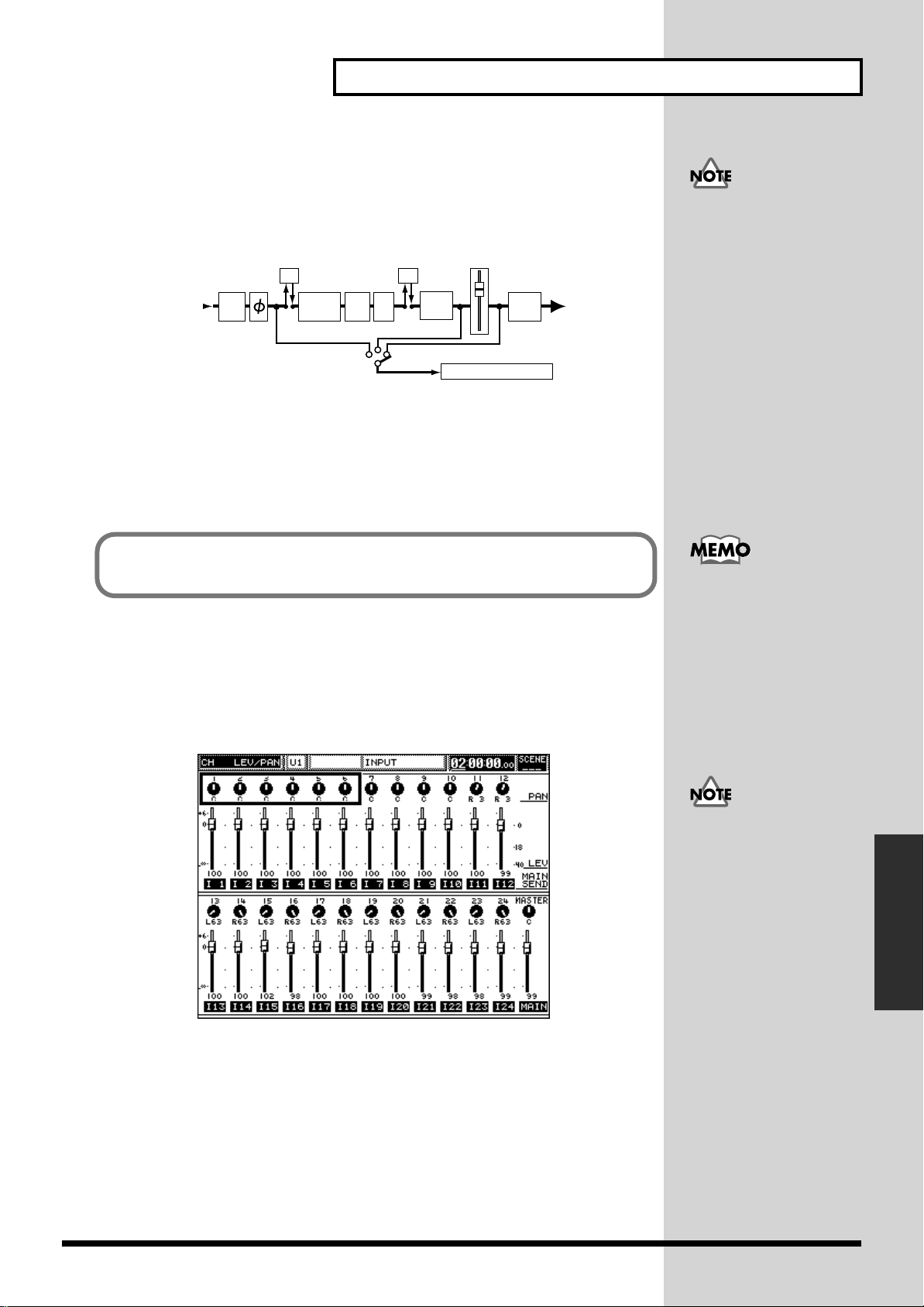
Chapter 5 Mixing Procedure 1 (Input Channel)
7. Choose the point from within the channel’s signal flow from which signal
will be sent to the Flex Buses.
Use CURSOR [UP] to select the region shown in the figure on the right, and then use
the [V1] to [V6] knobs to select the desired points. You can choose PreEQ, PreFD (Pre
Fader) or PstFD (Post Fader). Confirm your choices using [F1] to [F6] (SET).
fig.05-08
Channel Input
ATT
FX FX
HPF
EQ
PRE FADER
DELAY
PRE EQ
MUTE
POST FADER
FADER
MAIN
SW
FLEX BUS 1 (...12)
■ PAN and DEPTH for using SURROUND
This system supports surround sound in thee formats: 2+2, 3+1 and 3+2+1.
Surround sound allows signals to be positioned within a two-dimensional, left/
right/rear/front field. You can set each channel’s surround location, or “surround
panning.”
To adjust the sends for Flex
Buses 7–12, select the
second set of Flex Buses in
Step 4 above.
To set up surround panning, begin by activating the surround function on the
SYSTEM SURROUND screen (p. 91) and select a surround format or mode.
Setting up surround panning using PARAM VIEW on Fader
1. Press [INPUT] or [MULTI IN] in the SECTION area to select the type of
input you want to set up.
2. Press [CH PAN] in PARAM VIEW on Fader.
fig.05-09
Using PARAM VIEW on
Fader, you can set multiple
channels’ surround PAN
(right-left position) and
DEPTH (rear-front
position) using a Fader or
the V1 to V6 knobs.
When SURROUND PAN
SLAVE is switched off on
the SYSTEM SURROUND
screen (p. 91), [CH PAN]
cannot be used for setting
surround panning.
Chapter 5 Mixing Procedure 1
(Input Channel)
3. Set the left/right position for each channel using its fader.
4. Press [PREAMP GAIN] in PARAM VIEW on Fader while holding down
[SHIFT] and select SURROUND DEPTH.
5. Set the rear/front position for each channel using its fader.
• You can view a graphic display of your surround pan settings from the
SURROUND page in CHANNEL EDIT mode (p. 74).
● On the SURROUND
page in CHANNEL EDIT
mode, you can view each
channel’s surround
panning in graphs. You can
also set up each channel’s
surround panning in
conjunction with its
adjacent channel, and finetune its output level from
this screen.
73
Page 75

Chapter 5 Mixing Procedure 1 (Input Channel)
b
Setting surround panning in CHANNEL EDIT mode
* The figure on the screen shot below shows an example of surround with the
3+2+1 system selected. If the 2+2 or 3+1 system is selected, blank space is
displayed for output channels (Flex Buses) not being used.
1. Press and select [INPUT] or [MULTI IN] in the SECTION area to select the
type of input you want to set up.
2. Press the desired channels’ [CH EDIT].
3. Use [PAGE UP]/[PAGE DOWN] to select the SURROUND page.
4. Using CURSOR [UP]/[DOWN], select the region in the figure
(SURROUND PAN and STEREO LINK).
fig.05-10
● You can quickly jump to
this screen by pressing the
SURROUND STATUS
utton while holding down
the channel’s [CH EDIT].
● In the displayed graph,
the surround position for
the channel is shown as a
white circle. As new
settings for PAN and
DEPTH cause the white
circle to move, a shadow of
its original position
remains on the screen. To
erase the shadow, press
CURSOR [UP] and then
[F1] (REFRESH).
5. Set the channel’s right/left position using the V1 (PAN) knob, and rear/
front position with the V2 (DEPTH) knob.
6. Set up the desired balance between your surround system’s front speakers
(“center”: “left and right”) using the V3 (LR: C) knob.
You can set the balance—expressed as a percentage—between the right and left
speakers in your surround system in 3+1 or 3+2+1 mode.
When using surround, adjacent odd/even input channels can be linked and handled
as a stereo pair.
fig.05-11
● In the displayed graph,
the position of the channel
to which the currently
selected channel is linked is
shown as a black circle.
74
Page 76

Chapter 5 Mixing Procedure 1 (Input Channel)
j
Linking a channel to its adjacent odd/even partner
1. Move the cursor to STEREO LINK on the screen.
Follow Steps 1 to 4 in the previous section, “Setting surround panning in CHANNEL
EDIT mode” to move the cursor to STEREO LINK.
2. Use the V4 knob to select the desired linking method.
OFF: No linking.
PARALLEL: Position of the linked pair is set while preserving the
relative positions of the two channels in relation to each
other.
LINE SYMMETRY: Linked channels are positioned in line symmetry against
the vertical center line.
POINT SYMMETRY: Linked channels are localized in point symmetry against
the center point.
You can set the output level of a Flex Bus used for surround output independently
from the surround PAN and DEPTH settings. This allows you to make final fine
adjustments.
Fine adjustment of surround output level balance
1. Call up the SURROUND page in CHANNEL EDIT mode.
Follow the Steps 1 through 3 for “Setting surround panning in CHANNEL EDIT
mode” (p. 74) to display the SURROUND screen.
2. Use CURSOR [DOWN] to select the FRONT, REAR and SUBWOOFER.
3. Make the desired fine adjustment to the level using the V1 through V6 knobs.
The display shows each knobs’ associated Flex Bus number and speaker.
* You can temporarily turn off the output of a Flex Bus by pressing the
corresponding F1 through F6 button.
Turning the V1 through V6 knobs can cause the surround positioning to disagree
with the settings in the SURROUND PAN section of the display (PAN, DEPTH and
LR:C) and the displayed surround graph. If this occurs, “ACTIVE” in the screen is
automatically switched off.
Use CURSOR [UP] to select
SURROUND PAN, and
then press [F1] (ACTIVE) to
turn surround on again.
This cancels any
problematic fine
adjustments made to the
Flex Bus so that the actual
surround sound once again
matches the displayed
values.
When you activate MIDI JOYSTICK CONTROL on the SYSTEM SURROUND screen
(p. 91), and you can perform surround panning using a MIDI joystick. The joystick
will control the channel for which [CH EDIT] was most recently pressed. You can use
the joystick even when a screen other than the SURROUND screen is being
displayed.
■ Setting up direct-output channels
Input channel signals 1 through 24 can be sent directly to the corresponding multiout channels. When this is the case, signals sent to multi-out Channels 17 through 24
are also sent to ASSIGNABLE OUT jacks 1 through 8, respectively. This makes it
possible to directly access analog signals from the input channels.
It’s also possible to send an input channel’s signal to a number of multi-out channels
at the same time. Note, however, that multiple input signals cannot be directly sent
to a single multi-out channel. Each already-in-use channel is displayed as a broken
line. The direct connection of multi-in channels to multi-out channels is not possible.
● The system supports the
use of the MCS PANNER
oystick from J. L. Cooper,
which can be connected to
the console's MIDI IN jack.
● The signals sent to multiout Channels 21 and 22 are
also sent to DIGITAL
OUTPUT A (L, R). The
signals sent to multi-out
Channels 23 and 24 are also
sent to DIGITAL OUPUT B
(L, R).
75
Chapter 5 Mixing Procedure 1
(Input Channel)
Page 77

Chapter 5 Mixing Procedure 1 (Input Channel)
Preparing to send input channels to multi-outs in CHANNEL EDIT mode
1. Press [INPUT] in the SECTION area.
2. Press the desired channel’s [CH EDIT].
3. Use [PAGE UP]/[PAGE DOWN] to select the MAIN/CUE page.
You can jump to this screen by pressing the [MAIN/CUE] STATUS button while
holding down the desired channel’s [CH EDIT].
4. Use CURSOR [UP] to select the parameters in the upper section.
fig.05-13
The following settings can
also be accessed for all
channels at once by
pressing [MULTI OUT] in
the SECTION area and
pressing [CH EDIT] for the
multi-out channel you
want to set up (p. 93).
5. Select the output channel to which you want to send the input channel’s
signal.
Select the desired MULTI-OUT with the V1 (MULTI OUT SEL) knob, then press [F3]
(SET) to confirm your choice.
Setting the send level and point to a MULTI OUT
To set up SEND LEVEL to MULTI OUT using the V5 (LEVEL) knob, follow Step 5
above and press CURSOR [DOWN] to select the parameters in the middle section.
This allows you to select a point from within the channel’s signal flow from which
its signal will be sent to the selected MULTI OUT.
fig.05-14
You can press [F3] again to
cancel your output
selection, if you wish.
fig.05-15
76
Turn the [V4] (SEND POSI) knob to select PreEQ, PreFD (Pre Fader) or PstFD (Post
Fader). Press [F4] (SET) to confirm your selection.
Channel Input
ATT
FX FX
DELAY
PRE EQ
EQ
HPF
PRE FADER
MUTE
POST FADER
FADER
MAIN
SW
MULTI OUT 1–24
Page 78

Chapter 5 Mixing Procedure 1 (Input Channel)
b
b
Switching the Status of a Channel
The STATUS button above each fader switches the status of the corresponding input
channel. The STATUS button can change the following four items:
Mute: When on, silences the channel’s signal.
Solo: When on, isolates the channel’s signal, silencing other
channels.
Audio: Switches the track status of connected external recording
devices.
Auto-mix: Activates or de-activates automation recording of channel-
setting changes.
Press the MODE buttons in the CH STATUS area—[MUTE], [SOLO], [AUDIO] or
[AUTO-MIX]—to select the item you want to set using the STATUS button.
fig.05-16
This section describes the operation of the MUTE and SOLO buttons.
■ Muting a channel (MUTE)
Signals on input channels—both input and multi-in channels—can be muted using
the STATUS button.
Muting with the STATUS button
1. Press the [MUTE] in the CH STATUS MODE area—the button will light
when muting is activated.
2. Select either [INPUT] or [MULTI IN], depending on the type of channel
you want to mute.
3. Press the desired channel’s STATUS button so that it lights.
Any channels selected with SECTION buttons can be muted using the same
procedure, including [FADER GROUP] (Group 1–24), [FLEX BUS] (Flex Buses 1 –12)
and [MULTI OUT] (Multi Out 1–24).
fig.05-17
Audio Status (p. 192)
Auto-mix Status (p. 201)
Muting signals on input
and multi-in channels
causes all of their signals to
e muted, including those
sent to Flex Buses and cue
usses, unless their send
points are set to Pre EQ.
(For details, see the
attached block diagram
with the processor.)
If you wish, you can also
switch the MUTE function
on or off from the VIEW
page on the MUTE GROUP
SETUP screen (p. 103). You
can also mute a channel by
setting MUTE on CH
EDIT’s MAIN/CUE page.
Chapter 5 Mixing Procedure 1
(Input Channel)
Call up the screen by pressing the MAIN/CUE STATUS button while holding down
the desired channel’s [CH EDIT]. To mute the channel, press [F6] (MUTE)—the
channel’s MUTE indicator in the displayed graph will be shown as a reversed image.
77
Page 79
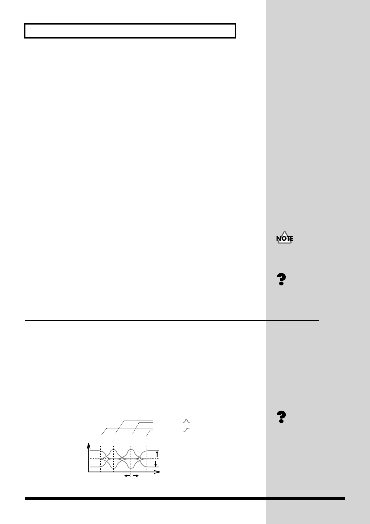
Chapter 5 Mixing Procedure 1 (Input Channel)
■ Listen to a channel by itself (SOLO)
Channel signals—both input and multi-in—can be set to SOLO mode in which all
the other channels are temporarily muted, allowing you to listen to the channel alone
(SOLO). SOLO mode sends the soloed channel’s signal to the following outputs:
• The mixing processor’s MONITOR OUT jack
• The console’s MONITOR LINE OUT jack
• Headphones connected to the console’s PHONES jack
Using the STATUS button to enter SOLO mode
1. Press the [SOLO] in the CH STATUS MODE area so that the button lights.
2. Select either [INPUT] or [MULTI IN], depending on the type of channel
you want to solo.
3. Press the desired channel’s STATUS button so that the button lights—all
other channels are silenced so that you can listen to the selected channel by
itself.
4. If you want to solo additional channels, press their STATUS buttons.
Press [STATUS] again to un-solo a channel—the button’s light turns off. When all
soloed channels have been un-soloed, the SOLO function is switched off.
If IN PLACE (Solo In Place) is selected on the SOLO screen (p. 68), signals are heard
as they are in the main mix, with their main-mix panning preserved, for example.
Otherwise, if PRE EQ or PEL (Pre Fader Listen) is selected, the cue bus is used for
soloed signals.
When IN PLACE is selected, all other signals in the main mix are muted except for
soloed channels. Therefore, when IN PLACE is selected, do not use the SOLO
function during the recording of a mix, when sending the MAIN OUTs to a stage
speaker system or when broadcasting from the MAIN OUTs.
In this case, do not use the
cue bus for purposes other
than monitoring.
IN PLACE (p. 238)
PFL (p. 242)
Adjusting Various Channel Settings (Equalizer, etc.)
All input and multi-in channels are equipped with parametric equalizers and HPF
(high-pass-filter) equalizers that allow you to alter the change the frequency
characteristics of the channel’s signal. Each channel also contains a feedback delay
function that allows you to generate echo and comb-filter effects.
■
Adjusting frequency characteristics (channel equalizer)
How the channel equalizer works
The channel equalizers (EQ) incorporated in this system parametric equalizers in
which switching between 4-band and 3-band + 1-filter modes is possible. High- and
low-frequency EQ bands are shelving EQs, while the high-middle and low-middle
bands are peaking EQs.
fig.05-18
Peaking type
Shelving type (p. 244)
Peaking type (p. 242)
Level
LO
LO
MIDHIMID
Shelving type
HI
78
0dB
FREQ
GAIN
Frequency
Page 80
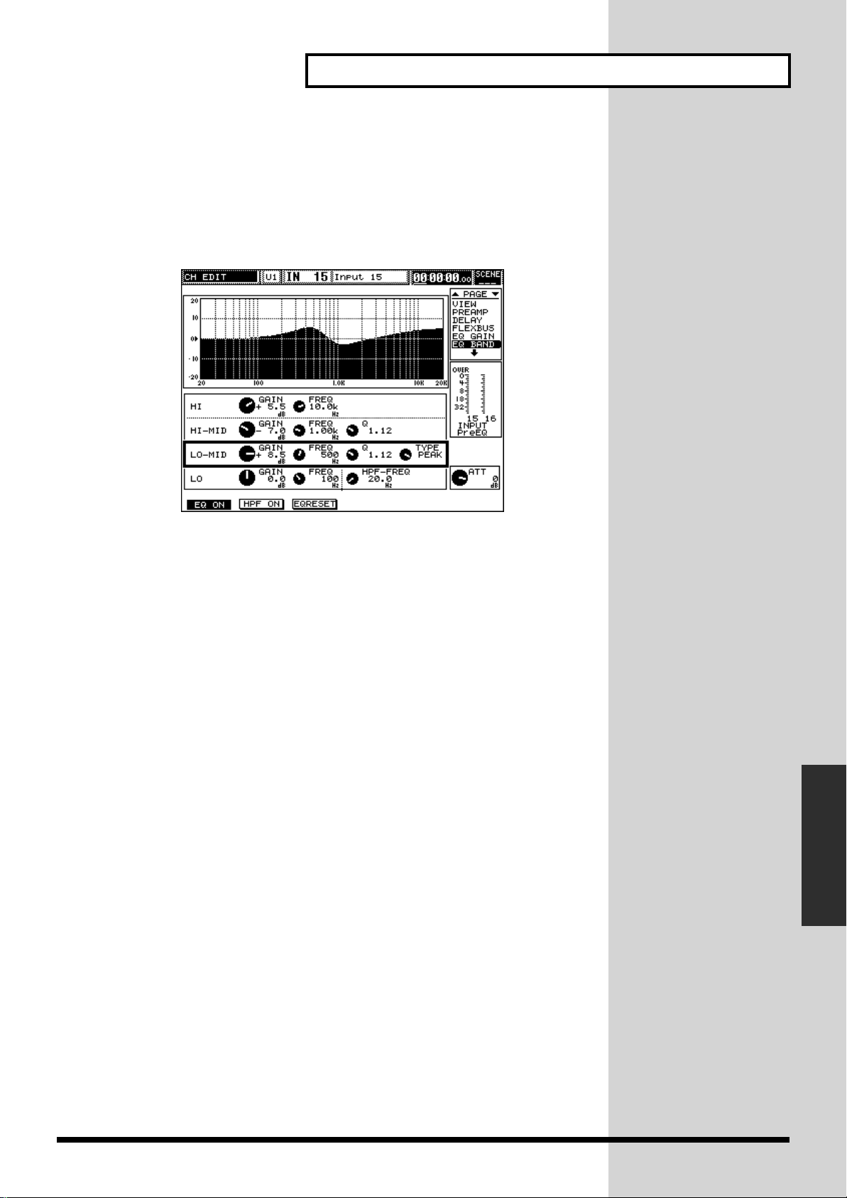
Chapter 5 Mixing Procedure 1 (Input Channel)
b
Setting up equalizers by band
1. Press and select [INPUT] or [MULTI IN] in the SECTION area to select the
desired type of input.
2. Press the desired channel’s [CH EDIT].
3. Use [PAGE UP]/[PAGE DOWN] to select the [EQ BAND] page.
fig.05-19
4. Press CURSOR [UP]/[DOWN] to select a frequency band.
You can choose HI (high-frequency band), HI-MID (high-middle frequency band),
LO-MID (low-middle frequency band) or LO (low-frequency band). In the example
shown in the figure, LO-MID (low-middle frequency band) is selected.
● You can quickly jump to
this screen by pressing the
[HPF/LO], [LO-MID] or
[HI-MID/HI] STATUS
utton, as desired, while
holding down [CH EDIT]
for the channel you want to
edit.
5. Adjust the settings for the selected band.
* [V6] (ATT LEVEL) adjusts the EQ input attenuation level in the same manner
as [V3] on the input channel PREAMP screen.
GAIN: Use [V2] (GAIN) to set the level of the band’s selected
frequency. (-15.0 to +15.0 dB)
(central frequency
FREQ
Q: Use [V4] (Q or FREQ) to set the band’s bandwidth (Q), the
Type: Set using [V5] (TYPE). Available only for the LO-MID
):Use [V3] (FREQ) to select a frequency.
range of frequencies to be affected above and below the
central frequency. By increasing the value for Q (0.36 to 16),
a narrower range of frequencies is selected. Q is available
only for the HI-MID and LO-MID bands. When the LO band
is being edited, [V4] sets the HPF frequency; see p. 81.
band.
* If LPF, BPF, HPF or NOTCH is selected as the EQ type, the V4 knob controls
RESO (resonance), with settings from 0 to 27. Resonance boosts frequencies
around the filter cutoff frequency—the frequency selected with the FREQ
parameter—adding a edgy, whistle-like character to a signal. When NOTCH is
selected, the range of frequencies boosted using resonance is further narrowed.
● The frequency widths for
the EQ bands are as
follows:
HI: 1 k to 20 kHz
HI-MID: 400 Hz to 20 kHz
LO-MID: 20 to 8 kHz
LO: 20 to 2 kHz
Chapter 5 Mixing Procedure 1
(Input Channel)
79
Page 81

Chapter 5 Mixing Procedure 1 (Input Channel)
b
b
b
TYPE provides a variety of configuration choices for the LO-MID band:
OFF: Disables the LO-MID band altogether for simpler, three-
band EQ.
LPF: Acts as a low-pass filter (to cut off higher frequencies)
BPF: Acts as a band-pass filter (to cut off all frequencies other
than the selected frequency).
HPF: Acts as a high-pass filter (to cut off lower frequencies)
NOTCH: Acts as a notch filter (to sharply cut off the specified
frequencies)
PEAK: Acts as an ordinary peaking-type equalizer
fig.05-20
Level
Level
When you configure LOMID as LPF, BPF, HPF or
NOTCH, the channel’s
equalizer is set up in a 3-
and + 1-filter
configuration. The added
filter can aid in the creation
of extreme equalization
effects.
● The slope of these filters
is -12 dB/octave.
Frequency
LPF
Frequency Frequency
HPF
LevelLevel
Frequency
BPF NOTCH
Setting up equalizers (gain adjustment for all 4 bands at a time)
1. Press and select [INPUT] or [MULTI IN] in the SECTION area to select the
type of channel you want to edit.
2. Press the desired channel’s [CH EDIT].
3. Use [PAGE UP]/[PAGE DOWN] to select the EQ GAIN page.
4. Setting up parameters for equalizers
Use CURSOR [UP]/[DOWN] to select the parameters you want to adjust, and use
[V1] to [V6] to change their settings.
Slope (p. 245)
From this screen, you can
use [F1] (EQ ON) to switch
the entire equalizer for a
channel on and off—when
the EQ’s on, it’s
highlighted. Press [F3]
(RESET) to reset the
channel’s equalizer to its
asic settings, where no
frequency-boosting or cutting is in effect.
● Refer to “Setting up
equalizers (by band)” in the
previous section.
● You can jump to this
screen can be displayed by
pressing the [EQ GAIN]
STATUS button while
holding down the
channel’s [CH EDIT].
For example, if the cursor is placed on the figure on the left, GAIN for the four bands
can be adjusted at the same time using the V1 (LO GAIN), V2 (LO-MID GAIN), V3
(HI-MID GAIN) and V6 (HI GAIN) knobs. If the cursor is placed on the figure on the
right, the attenuation level can be adjusted with the V6 (ATT LEVEL) knob.
* The attenuator on this screen operates in the same manner as [V3] on the input
● The parameters below
operate in the same manner
as their counterparts in
“Setting up equalizers (by
and).”
channel PREAMP screen.
* These settings can also be accessed from the CH EDIT VIEW screen (p. 63).
80
Page 82

Chapter 5 Mixing Procedure 1 (Input Channel)
■
Cutting unwanted low frequencies (HIGH PASS FILTER)
HPF (HIGH PASS FILTER) reduces the level of frequencies below a selected cutoff
frequency. Each channel contains a high-pass filter as device separate from the
channel’s EQ. An HPF has only two settings: ON/OFF and Cutoff Frequency.
Setting up a high-pass filter
1. Press [INPUT] or [MULTI IN] in the SECTION area to select the type of
input channel you want to work with.
2. Press the desired channel’s [CH EDIT].
3. Use [PAGE UP]/[PAGE DOWN] to select the EQ BAND page.
4. Turn the high-pass filter on or off.
Press [F2] (HPF ON) to switch between ON and OFF. The function is on if its label is
highlighted in black.
5. Move the cursor to the bottom of the screen, then set the cutoff frequency
for the high-pass filter using [V4].
● You can jump to this
screen by pressing the
HPF/LO or HI-MID/HI
STATUS button while
holding down the
channel’s [CH EDIT].
You can select a cutoff
frequency from 20 Hz to 2
kHz.
* You can accomplish a similar effect with channel EQ, as described on p. 79. Use
CURSOR [DOWN] to move the cursor on the bottom section, and then establish
the desired setting using the V4 knob.
■ Adding an delay-based echo (Feedback Delay)
Each channel offers a feedback delay inserted before the equalizer in the channel’s
signal flow. This delay is a monaural and provides various types of delay effects,
including an echo effect.
Setting up a channel’s feedback delay
1. Press and select [INPUT] or [MULTI IN] in the SECTION area to choose the
type of channel you want to work with.
2. Press the desired channel’s [CH EDIT].
3. Use [PAGE UP]/[PAGE DOWN] to select the DELAY page.
fig.05-21
The slope of this HPF is -6
dB/octave. (see p. 245.)
Chapter 5 Mixing Procedure 1
(Input Channel)
4. Turn the feedback delay on or off.
Press [F1] (DLY ON) to switch CHANNEL DELAY between on and off—when it’s
● You can jump to this
screen can be displayed by
pressing the [DELAY]
STATUS button while
holding down the desired
channel’s [CH EDIT].
81
Page 83

Chapter 5 Mixing Procedure 1 (Input Channel)
b
on, DLY ON is highlighted in black.
5. Press CURSOR [DOWN] to access up the parameters in the bottom section
of the display:
Level of the direct sound: Turn [V1] (DIRECT) from 0 to 127 to set the amount
of the original, un-delayed signal to be heard.
DELAY TIME: Turn [V4] (TIME) to select an amount of delay from
0 to 14,400 samples.
* DELAY TIME defines the length of the delay and the time interval of repeats.
* “Sample” is the smallest unit of time on this system. One sample represent a time
duration of about 0.021 ms at 48 kHz, or about 0.023 ms at 44.1 kHz.
The current setting is displayed as a DISTANCE in meters from the sound source.
The setting is also displayed in TIME as milliseconds based on the current sample
rate.
In DISTANCE on the screen, the setting is displayed as converted into a distance
from the sound source (in meters). In TIME, the setting is displayed as converted into
time (in ms = 1/1000 second) based on the current sample rate.
Level of delay sound: Turn [V2] (DLYLEVEL) from 0 to 127 to set the level
of the delayed signal.
Feedback level: Turn [V2] (F-B LEVEL) from 0 to 127.
* Feedback level determines how many times the delay sound is to be repeated.
6. Press CURSOR [UP] to access the parameters in the top section of the
display.
• To set the amount of attenuation below the selected LO DAMP FREQ, turn [V1]
(LO DAMP GAIN) from -30.0 to +6 dB.
• To select the frequency below which attenuation will occur, turn [V2] (LO
DAMP FREQ). You can select any frequency from 20 Hz to 2 kHz.
• To set the amount of attenuation above the selected HI DAMP FREQ, turn [V3]
(HI DAMP GAIN) from -30.0 to +6 dB.
• To select the frequency above which attenuation will occur, turn [V4] (HI DAMP
FREQ). You can select any frequency from 200 Hz to 20 kHz.
The DELAY TIME
parameter works in
conjunction with the
PHASE DELAY parameter,
which also allows you to
delay a channel’s signal by
small increments to correct
phasing problems (p. 69).
Together, their delay times
cannot exceed 14,400
samples in total.
● The high (low) frequency
damping function allows
you to attenuate the level of
delayed sounds above or
elow a specified
frequency. This can help
produce a naturalsounding echo effect (p.
238).
With the proper settings,
the feedback delay function
can also be used as a comb
filter (p. 233).
82
Page 84

Chapter 5 Mixing Procedure 1 (Input Channel)
b
b
■ Naming input channels
You can assign a name to each input channel and multi-in channel—this can make it
easier to identify your individual signals as you work. You can use short names, such
as “Vo3,” with up to 3 characters, and long names, such as “Vocal 03,” with up to 12
characters.
Creating channel names
1. Press [INPUT] or [MULTI IN] in the SECTION area to select the type of
channel you want to name.
2. Press the desired channel’s [CH EDIT] so that the button lights.
3. Use [PAGE UP]/[PAGE DOWN] to select the NAME page
fig.05-22
Long names are displayed
in the top section on the
channel-related screens.
Short names are displayed
on screens such as the
LEVEL METER screen (p.
36).
4. Spell out the channel’s name by selecting each character position and
assigning it the desired character.
Turn [V3] (CURSOR POS) to select the each character position you want to edit.
5. When you’ve selected the character position, enter the desired character
using the following knobs.
• upper-case letters (A–Z) by turning [V4] (ABC).
• lower-case letters (a–z) by turning [V5] (abc).
• numbers and symbols (1, 2, 3, !, “, #) by turning [V6].
[F2] to [F5] provide additional naming shortcuts:
[F2] (DELETE): Deletes the character at the currently selected position and
moves the following characters forward.
[F3] (INSERT): Inserts a space at the currently selected position and pushes
the following characters back.
[F4] (SPACE): Replaces the character at the currently selected position
with a space.
[F5] (REVERT): Discards names previously created to restore the initial
characters.
EZ naming function
Names for the respective channels can be selected from a list of category names
permanently stored in the system’s memory at the factory. This function is referred
to as easy naming (EZ NAMING). You’ll find the list on the NAME page. Use [V1]
(CATEGORY) and [V2] (NUMBER) to select and enter the desired name.
• Select a category name from the list using [V1] (CATEGORY).
• Select a number to be attached to the end of the name using [V2] (NUMBER).
● Press [F1] (ASCII) to
enable the entering of
characters using buttons—
when name-editing is
active, ASCII is highlighted
in black. You can press the
uttons on the front panel
that are labeled with
individual letters—[CH
EDIT]s, STATUS buttons,
ten-key pad, etc.—to enter
those letters. You can also
enter:
Channel names are stored
in the system’s memory
using the SAVE function
along with other channel
parameters such as LEVEL
and PAN.
● Turn [V2] to alternate
etween changing the
number at the end of the
channel’s long and short
names.
Chapter 5 Mixing Procedure 1
(Input Channel)
83
Page 85

Chapter 6 Mixing Procedure 2 (Output and Monitor)
This system provides a variety of output types: MAIN OUTs, MONITOR OUTs,
ASSIGNABLE OUTs and two stereo digital audio outputs. In addition, when a VM24E (purchased separately) is installed, 24 MULTI OUT connections—utilizing three
R-BUS terminals—become available. The VM-7200 mixing processor adds an
additional eight independent Flex Bus outputs.
This chapter describes using these outputs.
Setting Master Mix Levels and Stereo Balance
Each input and multi-in channel can be routed into the main mix, which sends its
audio out of the system through the MAIN OUT outputs. You can adjust the
channel’s send into the main mix, as well as its stereo pan position within the mix.
You can also send the desired amount of signal from each channel to the cue bus.
■ Setting the master levels for the MAIN OUTs and cue
bus
The master MAIN OUT and cue bus level and stereo balance controls affect the
overall level and balance of all signals sent to the main mix or cue bus from input or
multi-in channels. They can be set using the master fader—the fader with the red
handle.
To learn how to establish
proper output connections,
refer to the block diagram
attached to the mixing
processor.
Setting the MAIN OUT master level and stereo balance
1. Press [INPUT] or [MULTI IN] in the SECTION area.
2. Call up the MAIN OUT level setting by pressing [CH LEVEL] in the
PARAM VIEW on Fader area so that the button turns red.
3. Use the master fader to set the MAIN OUT master level.
fig.06-01
4. Call up the MAIN OUT stereo balance setting by pressing [CH PAN] in the
PARAM VIEW on Fader area so that the button turns red.
5. Use the master fader to set the MAIN OUT master stereo balance.
Setting the master level of the cue bus
1. Press [INPUT] or [MULTI IN] in the SECTION area.
The master fader controls
the MAIN OUT left/right
stereo level balance when
[CH PAN] is pressed.
2. Call up the cue bus master level setting by pressing [CH LEVEL] (CUE
LEVEL) beneath the master fader while holding down [SHIFT].
The CH LEVEL button turns green.
84
Page 86

Chapter 6 Mixing Procedure 2 (Output and Monitor)
3. Use the master fader to set the cue bus master level.
fig.06-02
4. Call up the cue bus master stereo balance by pressing [CH PAN] (CUE
PAN) in the PARAM VIEW on Fader area while holding down [SHIFT].
The CH PAN button turns green.
5. Use the master fader to set the cue bus master stereo balance.
■ Reducing signal distortion (attenuator)
Press the master fader’s [CH EDIT] to set the master attenuators. These attenuators
help control the combined level of all of the signals coming into the main mix and
cue bus.
fig.06-03
The master fader controls
the cue bus’s stereo balance
when [CH PAN] (CUE
PAN) is pressed. As a
result, it cannot be used for
setting levels while in this
operating mode.
Setting the MAIN OUT attenuator
1. Press [INPUT] or [MULTI IN] in the SECTION area.
2. Press the master fader’s [CH EDIT] and CURSOR [UP], in that order.
3. Turn [V1] (MAIN BUS ATT LEVEL) to set the MAIN OUT attenuator.
Setting the cue bus attenuator
1. Press [INPUT] or [MULTI IN] in the SECTION area.
2. Press the master fader’s [CH EDIT] and CURSOR [UP], in that order.
3. Turn [V3] (CUE BUS ATT LEVEL) to set the cue bus attenuator.
Chapter 6 Mixing Procedure 2
(Output and Monitor)
85
Page 87

Chapter 6 Mixing Procedure 2 (Output and Monitor)
b
A Flex Bus and Its Output
A bus is a pathway down which one or more signals can travel to a common
destination. A bus can be routed to an internal effect, an external device or to another
bus.
This system is equipped with Flex Buses and cue buses. (When this book uses the
simple term “bus,” it refers to a Flex Bus.)
Refer to the bus diagram in
“Internal Signal Flow” (p.
29).
What is a Flex Bus?
A Flex Bus is a powerful, general-purpose bus. Each VM mixing processor offers 12
Flex Buses. Flex Buses can be used for various purposes such as sending signal to
external equipment, sending a group of channel signals to internal effects, and
sending audio to separate monitors on a stage.
■ Outputting signals directly from a Flex Bus
A Flex Bus’s signal can exit the system through an ASSIGNABLE OUT. On the VM7200 processor, you can also use the output jacks dedicated to Flex Buses 5 to 12
(FLEX BUS OUT). When an optional VM-24E, purchased separately, is installed, Flex
Bus signals can be routed to digital MULTI OUT connections.
To route a Flex Bus to an output, you must set its mode to EXT, for “external output.”
Setting Flex Bus 1 to 8 to external output mode
1. Press [FLEX BUS] MASTER 1–12 in the SECTION area to configure the
channel strips for the control of Flex Buses.
2. Press the desired Flex Bus channel’s [CH EDIT].
● Flex Buses 1 to 8 behave
in a slightly different
manner than Flex Buses 9
to 12. For details, refer to
the block diagram attached
to the processor.
● FLEX BUS OUTs 7 to 12
are equipped with XLR
connectors as well.
Since Flex Buses 9 to 12
have their own dedicated
output jacks, they don’t
require an EXT setting.
3. Use [PAGE UP] or [PAGE DOWN] to select the [MAIN/CUE] page.
fig.06-05
4. Set the bus mode.
Navigate to the above screen using CURSOR [UP] or [DOWN] and select use [V2]
(BUS MODE) to select EXT. Press [F2] (SET) to confirm the selection.
86
● You can jump to this
screen by pressing the
MAIN/CUE STATUS
utton while holding down
the Flex Bus channel’s [CH
EDIT].
Pressing [F1] (CHANNEL
LINK) in the Step 4 above
turns stereo linking (p. 102)
to the adjacent Flex Bus on
or off. When linking is on,
the parameter is
highlighted in black on the
display.
Page 88

Chapter 6 Mixing Procedure 2 (Output and Monitor)
j
b
The Flex Bus is now set to use an external output.
To use the VM-7100—which does not provide FLEX BUS OUT jacks—or output
signals from Flex Buses 1 to 4, select a MULTI OUT or ASSIGNABLE OUT as
follows:
Selecting a Flex Bus’s output
1. Call up a Flex Bus’s MAIN/CUE page as described in Step 3 in the
previous section.
2. Press CURSOR [UP] to select a parameter in the upper area of the display.
3. Select the desired MULTI OUT using the V3 knob (MULTI OUT SEL) and
press [F3] (SET) to confirm your selection.
fig.06-06
You can also access this
setting from a multi-out
channel. To do this, press
[MULTI OUT] in the
SECTION area to configure
the channel strips as multiout channels and press the
desired multi-out channel’s
[CH EDIT] (p. 93).
To reset the MULTI OUT
selection, press [F3] (SET)
again.
● Any signals sent to
MULTI OUTs 17 to 24 are
also routed to
ASSIGNABLE OUTs 1 to 8,
respectively. To route a
Flex Bus’s signal to one of
the analog ASSIGNABLE
OUTs, select the
corresponding MULTI
OUT (17 to 24).
■ Sending Flex Bus signals to internal destinations
To send a Flex Bus’s signal to another Flex Bus, the main mix or to the cue bus, set
the Flex Bus’s mode to INT, for “internal destination.”
Setting up Flex Bus 1 to 8 for internal use
1. Press [FLEX BUS] MASTER 1–12 in the SECTION area.
2. Press the desired Flex Bus channel’s [CH EDIT].
3. Use [PAGE UP] or [PAGE DOWN] to select the [MAIN/CUE] page.
4. Set the bus mode.
Use CURSOR [UP] or [DOWN] to select the display’s middle section and use [V2]
(BUS MODE) to select INT. Press [F2] (SET) to confirm the selection.
When the set of parameters
located in the middle
section of the display is
selected, you can set the
Flex Bus’s output level
using the V5 knob
(LEVEL).
Since Flex Buses 9 to 12 are
always routed to their
respective FLEX BUS OUT
acks, they cannot be routed
to internal destinations.
● You can jump to this
screen by pressing the
MAIN/CUE STATUS
utton while holding down
the Flex Bus channel’s [CH
EDIT].
Chapter 6 Mixing Procedure 2
(Output and Monitor)
87
Page 89
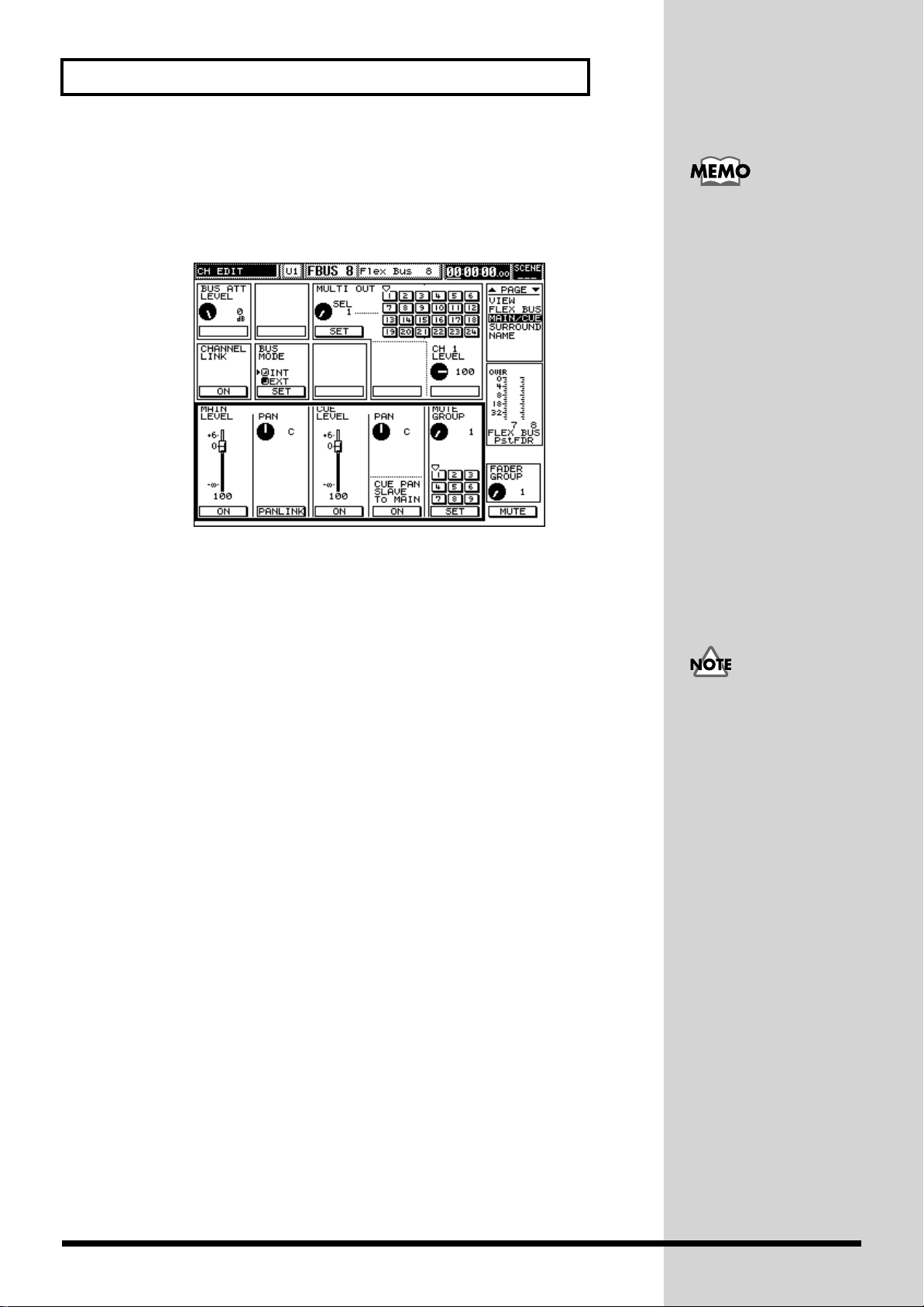
Chapter 6 Mixing Procedure 2 (Output and Monitor)
Sending signals to MAIN OUT or cue bus
Flex Bus levels or panning can also be set from this screen.
1. Follow step 4 in the previous section, and use CURSOR [DOWN] to select
the parameters in the lower section of the display.
fig.06-08
They can also be set on the
PARAM VIEW on Fader
screen (p. 64).
2. Set the Flex Bus’s send level and pan to the MAIN OUT jacks:
Flex Bus send to the main mix Use the V1 knob (MAIN LEVEL) to select
the desired level from infinity to +6 dB.
Flex Bus panning in the main mix Use the V2 knob (MAIN PAN) to choose
the desired pan position, from L63 to R63.
The following parameters can also be set from this display:
On/off switch for sending the Flex Bus to the main mix
Press [F1] (ON) to enable or disable the send. When the
send is active, it’s highlighted.
Pan-linking Set this parameter by pressing [F2] (PANLINK). When Flex
Bus pan-linking is active, it’s highlighted on the display.
When pan-linking is in effect, the V2 knob affects the stereo
placement of both linked Flex Buses in the main mix.
3. Set the cue bus send level and panning.
Flex Bus send to the cue bus Turn the V3 knob (CUE LEVEL) to set the Flex
Bus’s send to the cue bus, from infinity to +6 dB.
Flex Bus pan to the cue bus Turn the V4 knob (CUE PAN) to select the desired
pan position for the Flex Bus, from L63 to R63.
The following parameters can also be set from this display:
On/off switch for sending the Flex Bus to the cue bus
Press [F3] (ON) to activate or de-activate the send to the cue
bus. When the send is active, it’s highlighted on the display.
Pan slave Press [F4] CUE PAN SLAVE To MAIN (ON) to activate
pan-slaving; when it’s on, it’s highlighted on the display.
Pan slaving sets the Flex Bus’s panning in the cue bus to be
the same as it is in the main mix.
When the level for MAIN
OUT feeding of the same
flex bus is the minimum,
feeding to a cue bus is not
outputted too. (Refer to the
block diagram attached to
the processor.)
88
Page 90
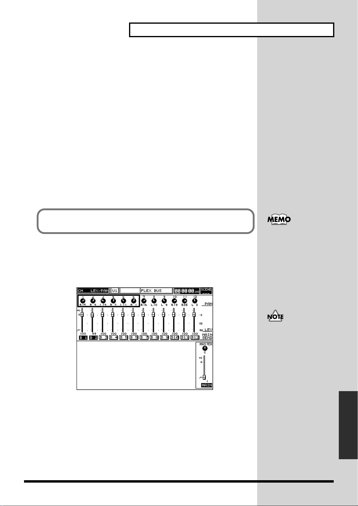
Chapter 6 Mixing Procedure 2 (Output and Monitor)
b
■ Naming a Flex Bus channel
Each Flex Bus channel can be named. This helps you quickly identify the purpose of
each Flex Bus. Long names (up to 12 characters) such as “Ext.Reverb” and short
names (up to 3 characters) such as “Rev” can be set for each channel.
Calling up the Flex Bus channel name screen
1. Press [FLEX BUS] MASTER 1–12 in the SECTION area.
2. Press the desired Flex Bus channel’s [CH EDIT].
3. Use [PAGE DOWN] to select the [NAME] page.
4. Use [F1] to [F5] and the V1 to V6 knobs to enter a name.
The remainder of the operation is exactly the same as the procedure for naming an
input channel. For details, refer to “Creating channel names” on p. 73.
■ Routing a Flex Bus to a surround system output
Signals in Flex Buses 1 to 6 can be used in a multi-speaker surround system, just as
an signals from input channels can.
To use the surround-panning function, enable the surround function on the system
surround screen (p. 91) and select a surround mode.
Setting surround PAN and DEPTH using PARAM VIEW on Fader
1. Press [FLEX BUS] MASTER 1–12 in the SECTION area.
2. Press [CH PAN] in the PARAM VIEW on Fader area.
fig.06-10
● Surround-panning refers
to the positioning of each
Flex Bus’s signal within
two front/rear and right/
left dimensions.
The PARAM VIEW on
Fader feature allows you to
change the surround PAN
and DEPTH parameter for
multiple channels at the
same time using their
faders of the V1 to V6
knobs.
When the SURROUND
PAN SLAVE feature is
turned off on the system
surround screen (p. 91), the
left/right positioning of
signals is not determined
y their individual main
mix pan settings.
Chapter 6 Mixing Procedure 2
3. Change each channel’s right/left position using its fader.
(Output and Monitor)
89
Page 91

Chapter 6 Mixing Procedure 2 (Output and Monitor)
4. While holding down [SHIFT], press [PREAMP GAIN] in the PARAM
VIEW on Fader area to select SURROUND DEPTH.
fig.06-11
5. Change the front/rear position of each channel using its fader.
● A Flex Bus can also be
surround-panned on
CHANNEL EDIT mode’s
SURROUND page on the
while viewing each
channel’s surround settings
graphically. You can also
set surround-panning for
linked channels, and fine
tune surround output
levels.
Calling up the CHANNEL EDIT mode screen
1. Press [FLEX BUS] MASTER 1–12 in the SECTION area.
2. Press the desired Flex Bus channel’s [CH EDIT].
3. Use [PAGE UP] or [PAGE DOWN] to select the [SURROUND] page.
fig.06-12
The following operations and screens are the same as those for surround-panning of
an input channel. For details, refer to p. 74.
The screen on the left
shows a situation is which
the 3+2+1 surround mode
is selected. When either the
2+2 or 3+1 mode is
selected, the unused Flex
Bus output is left blank on
the display.
● You can jump to this
screen can be called by
pressing the [SURROUND]
STATUS button while
holding down the Flex Bus
channel’s [CH EDIT].
90
Page 92

Surround Output
Chapter 6 Mixing Procedure 2 (Output and Monitor)
The system supports the use of multi-speaker surround sound. This section gives an
overview of how it works and explains how to use surround outputs.
The surround function
While a stereo system plays sounds through two speakers positioned right and left
in front of the listener, a surround system creates the illusion of a two-dimensional
sound space with the listener located in the middle. Surround uses three to six
speakers positioned in front of and behind the listener. There are several surround
modes, depending on the number and position of the speakers. This system supports
the following three most commonly used surround modes.
2+2: 4 speakers: front right, front left, rear right and rear left
3+1: 4 speakers: front right, front left, front center and rear center
3+2+1: 6 speakers: front right, front left, front center, rear right, rear left, and
Surround system playing environment
Surround sound utilizes a multi-channel amplifier and speaker system. Such a
system requires the number of speakers required for the selected surround mode, as
well as an amplifier capable of playing the required number of channels. You can
purchase a surround-type amplifier or several stereo amplifiers for this purpose.
Surround-output connections
When surround is enabled, some FLEX BUS OUTs become dedicated surround
output jacks. The selected surround mode determines the output configuration.
The correspondence between surround speaker positions and FLEX BUS OUT jacks
is as follows:
fig.06-13
● For how to surround-pan
each input channel, refer to
p. 74.
The 3+2+1 mode is also
called “5.1 surround.”
a sub-woofer)
You can record or play
multi-channel surround
sounds from two channels,
using a commerciallyavailable surround
encoder/decoder.
2+2
Connect these outputs to the appropriate input of your surround amplifier.
3+1
3+2+1
■ Enabling the surround function and selecting the
desired mode
The surround function can be enabled or disabled and its mode selected using the
procedure below. You can also use this procedure to select whether surround
panning will follow channel pan settings or be set using a joystick, purchased
separately.
Chapter 6 Mixing Procedure 2
(Output and Monitor)
91
Page 93

Chapter 6 Mixing Procedure 2 (Output and Monitor)
j
Setting up surround outputs
1. Press [PROJECT] ([SYSTEM) while holding down [SHIFT].
This calls up the system menu screen.
fig.06-14
2. Press CURSOR [UP] and then [F2], and select SURROUND.
fig.06-15
3. Turn on the surround master switch.
Use CURSOR [UP] to select a parameter in the upper section of the display. Press
[F1] (ON) and select [SURROUND CONTROL MASTER SW] on the screen—when
surround is turned on, it’s highlighted in black.
4. Set whether to use a joystick for surround panning, or not.
To control surround pan using an optional MIDI joystick, press [F2] (MIDI
JOYSTICK CONTROL).
5. Set whether or not surround panning will follow channel panning.
A signal’s left/right surround position (PAN) usually follows its channel pan
setting. Press [F3] (SURROUND PAN SLAVE) to disable this behavior—when
surround pan-slaving is turned off, it’s not highlighted on the display.
6. Select the desired surround mode.
Select a parameter in the lower section using CURSOR [DOWN] and press [F1] (2+2),
[F3] (3+1) or [F5] (3+2+1).
Surround panning
In a surround system, each channel’s signal can be separately positioned in two
dimensions, front/rear and right/left. This is called “surround panning.” The
signal’s position is controlled using two parameters, PAN for left/right positioning
and DEPTH for front/rear positioning.
• To set surround panning while viewing each channel’s position graphically, call
up the CHANNEL EDIT mode surround page (p. 74).
• To control the surround panning of multiple channels at the same time using
their faders, use PARAM VIEW on Fader (p. 74).
● The joystick will control
surround panning for the
channel whose [CH EDIT]
was most recently pressed.
The system is compatible
with J. L. Cooper’s MCS
PANNER. Connect the
oystick to the console’s
MIDI IN jack.
● Surround panning is
available for Flex Buses 1 to
6 (p. 89).
92
Page 94

Chapter 6 Mixing Procedure 2 (Output and Monitor)
Routing Signals to MULTI OUTs and ASSIGNABLE OUT Jacks
You can select the signal to be sent out of the system through each MULTI OUT
connection and ASSIGNABLE OUT jack.
• MULTI OUTs 1 to 24
• ASSIGNABLE OUTs 1 to 8
• DIGITAL OUTs A and B
The following (e.g. source and level) can be set for the above outputs.
■ Selecting an output’s signal source
One of the following can be selected as the source of the signal to be sent to each
output:
Input channels 1 to 24, Flex Buses 1 to 12, cue buses L and R, monitors buses L and
R, and main mix buses L and R.
You can set an input or Flex Bus channel’s output from its CHANNEL EDIT screen
(p. 67 and p. 87), or set the output routing for multiple channels at the same time
from the MULTI OUT CHANNEL EDIT screen.
MULTI OUT CHANNEL EDIT screen
1. Press [MULTI OUT] in the SECTION area.
2. Press the desired multi-out channels [CH EDIT].
This calls up the multi-out channel’s editing screen.
3. Use [PAGE UP] to select the [SOURCE] page.
fig.06-16
To use MULTI OUTs, a
VM-24E (purchased
separately) must be
installed in the system. A
MULTI OUT is a digital
output connection made
using a Roland R-BUS
connector.
A source that’s selected for
MULTI OUTs 17 to 24 will
also be sent to a
corresponding
ASSIGNABLE OUT, and,
in some cases, a DIGITAL
OUT. A signal sent to:
• MULTI OUTs 17 to 20
will also be sent to
ASSIGNABLE OUTs 1 to
4, respectively.
• MULTI OUTs 21 and 22
will also be sent to
ASSIGNABLE OUTs 5
and 6, respectively, and
to L and R of DIGITAL
OUT A
• MULTI OUTs 23 and 24
will also be sent to
ASSIGNABLE OUTs 7
and 8, respectively, and
to L and R of DIGITAL
OUT B
4. Select a source for the MULTI OUT output using the V1 knob (SOURCE
SELECT).
Straight lines show the connection of I/O channels on the screen.
Chapter 6 Mixing Procedure 2
(Output and Monitor)
The output level can be set
using the V2 knob (LEVEL)
if necessary.
93
Page 95
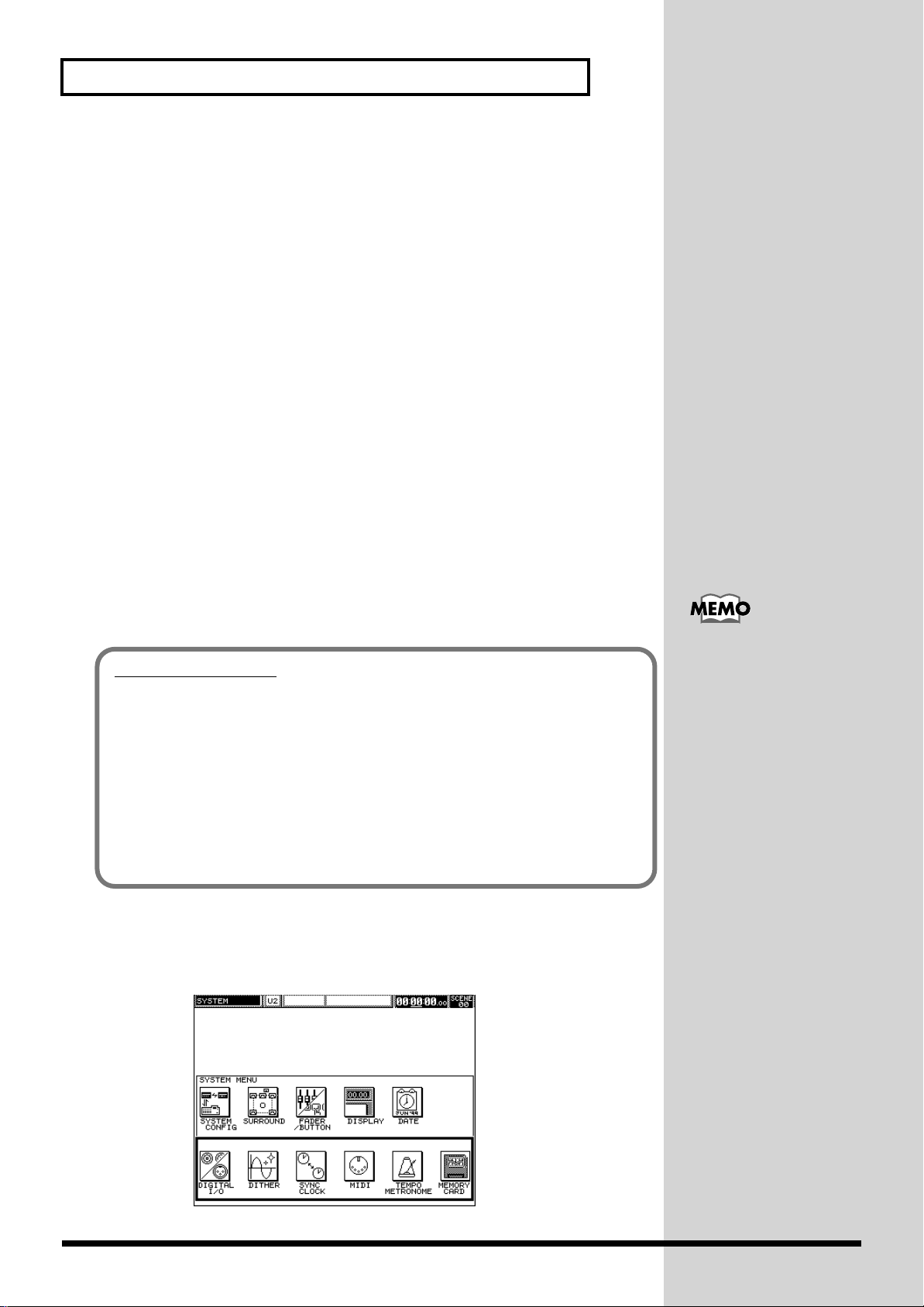
Chapter 6 Mixing Procedure 2 (Output and Monitor)
■ Naming each output channel
Each MULTI OUT (ASSIGNABLE and DIGITAL OUT) channel can be named so that
you can easily identify its purpose. Both long names (up to 12 characters) such as
“ADAT Tr1” and short names (up to 3 characters) such as “Tr1” can be set.
Calling up the multi-out channel name screen
1. Press [MULTI OUT] in the SECTION area.
2. Press the desired multi-out channel’s [CH EDIT].
This calls up the multi-out channel EDIT screen.
3. Select the [NAME] page using [PAGE DOWN].
4. Use [F1] to [F5] and the V1 to V6 knobs to enter a name.
The remainder of the operation is exactly the same as the procedure for naming an
input channel. For details, refer to “Naming input channels” (p. 83).
■ Setting an output’s level
1. Press [MULTI OUT] in the SECTION area.
2. Use each multi-out channel’s fader to set its overall output level.
■ Digital connection output processing (dithering)
MULTI OUT digital signals can be dithered.
What is dithering?
When digital audio signals are sent from one device (or computer program) to
another, some of the lower data bits will discarded if the bit resolution of the
receiving device is lower than that of the sending device. Dithering is a form of
digital processing that adds low-level noise to the signal to mask and reduce any
deterioration in the signal resulting from the lost bits.
To enable dithering, the word (bit) length—also called its “bit depth”—of the sender
must be adjusted to that of the receiver. When a 20-bit input digital multi-track
recorder is to be connected to MULTI OUT, set the word length to 20 on the VM
dither screen. Since dithering changes sound quality slightly, if the results are not
satisfactory, you can disable dithering for the affected channel.
Setting up dithering
1. Press [PROJECT] (SYSTEM) while holding down [SHIFT].
This calls up the system menu screen.
fig.06-14
To use MULTI OUTs, a
VM-24E (purchased
separately) must be
installed.
94
Page 96

Chapter 6 Mixing Procedure 2 (Output and Monitor)
b
2. Press CURSOR [DOWN] and then [F2], and select DITHER.
This calls up the dither-setting screen.
fig.06-20
3. Select the set of multi-out channels that contains the one you want to set.
Use CURSOR [UP], [DOWN], [LEFT] or [RIGHT] to select 1 to 6, 7 to 12, 13 to 18 or
19 to 24.
4. Enable or disable dithering and set the word length.
Press [F1] to [F6] (ON) in accordance with the directions on the screen to enable
dithering—when it’s on, it’s highlighted in black. Turn [V1] to [V6] (WORD
LENGTH) to sets the word length.
Setting Up Monitor Sends For Studio Or Stage (STUDIO 1 or 2)
ASSIGNABLE OUTs 1 to 4 can send signal to studio monitors used by a performer
in another room. You can set up two independent studio-monitor systems: STUDIO
1 and STUDIO 2. ASSIGNABLE OUTs 1 and 2 are used as the output jacks for
STUDIO 1 left and right, respectively, and ASSIGNABLE OUTs 3 and 4 for are used
for STUDIO 2.
Connect a studio headphone or monitor speaker amplifier input, or the equivalent,
to each STUDIO output jack.
Each monitor mix can be tailored to the needs of the performer listening to it.
STUDIO 1 has a dedicated level knob. If, for example, STUDIO 1 being used for the
monitoring of vocals on a stage, you can use the knob to quickly lower its level
should the unpleasant howling of feedback occur.
MONITOR OUT jack of VM-7200 processor
The VM-7200’s MONITOR OUT jack can send the signal heard in the CONTROL
ROOM monitors to a studio or stage. It can also be used in conjunction with STUDIO
1 and 2 outputs (ASSIGNABLE OUT jacks 1 to 4) when necessary, as discussed in the
next section.
● Select the word length
that matches the receiving
device’s input word length,
or bit depth, from 16 to 24
its.
● When you require a mix
in the cue bus that’s
different from the main
mix, you can create an new,
independent mix using
Flex Buses.
The STUDIO 1 and 2
settings affect the MULTI
OUTs and DIGITAL OUT
that are receiving the same
signals—for example, the
left side of STUDIO 1
receives the same signal as
MULTI OUT 17 and the left
side of stereo DIGITAL
OUT A. Therefore, when
changing STUDIO 1 or 2
settings, take care that your
new settings also work for
the corresponding MULTI
and DIGITAL OUTs if
they’re also being used.
Chapter 6 Mixing Procedure 2
(Output and Monitor)
95
Page 97

Chapter 6 Mixing Procedure 2 (Output and Monitor)
Selecting the STUDIO 1 or 2 source signal (source select)
1. Press [SOURCE/STUDIO2].
The STUDIO1/2 screen appears.
fig.06-21
2. Select STUDIO 1 or 2 using [PAGE UP] or [PAGE DOWN].
3. Select the desired source signal for STUDIO 1 or 2.
Turn [V1] (SOURCE SELECT) to select one of the following:
• INPUT CHs 1 to 24
• Flex Buses 1 to 12
• Cue buses L and R
• Monitors L and R
• Mains L and R
Setting the STUDIO 1 and 2 send level
1. Press [SOURCE/STUDIO2].
The STUDIO1/2 screen appears.
2. Select STUDIO 1 or 2 using [PAGE UP] or [PAGE DOWN].
3. Turn [V2] (LEVEL) to set the desired send level.
Setting Up a Monitor For the Mixing Engineer
A mixing engineer can monitor the system using a MONITOR jack on the console:
DIGITAL OUTs 1 and 2, or LINE OUT. The same signals can be heard through
headphones connected to the PHONES jack. They can also be sent to the MONITOR
OUT jack of the VM-7200 processor.
You can insert certain
effects—such as
equalization or speaker
modeling—in the monitor
output signal path (p. 110).
96
Page 98

Chapter 6 Mixing Procedure 2 (Output and Monitor)
b
■ Turning the monitor send to each output jack on or off
You can independently activate or de-activate the sending of monitor signals to the
following three jacks:
• MONITOR DIGITAL OUTs 1 and 2 on the console
• MONITOR LINE OUTs L and R on the console
• MONITOR OUT on the VM-7200 processor
Turning monitor signal send on or off
1. Press MONITOR/PHONES [SOURCE SELECT] while holding down
[SHIFT].
This calls up the monitor screen.
2. Use CURSOR [UP] to select the display area shown below.
fig.06-22
Monitor signal is always
sent to the PHONES jack.
To avoid hearing the
signal, turn down the
[PHONES LEVEL] on the
console.
You can store three presets
containing monitor output
assignments and levels in a
project. To create the three
presets, labeled “A,” “B”
and “C,” select each set in
turn and set its output
assignments and levels. To
select Preset A or B, press
OUTPUT PRESET [A/B/C]
—this toggles between the
two presets. To select C,
press OUTPUT PRESET
[A/B/C] while holding
down [SHIFT].
The same signals are sent to
3. Select a jack and turn its receipt of the monitor send on or off.
Turn the V4 knob (SEND SW) to select MONITOR on the processor, DIGITAL on the
console or LINE OUT on the console. Press [F4] (SET) to turn the selected monitor
output on (highlighted) or off.
■ Calling up stored level and monitor output presets
You can store three sets of monitor send assignments and levels—as described in the
previous section—in a project. Pressing the panel OUTPUT PRESET [A/B/C] to turn
the output target equipment on or off restores A, B, and C to the same status as that
obtained by returning each to its original position. In this case, the state of the
DIGITAL MASTER level on the display is also stored and recalled when setting A to
C, respectively.
fig.06-23
oth MONITOR DIGITAL
OUTs 1 and 2 on the rear of
the console. You can
monitor directly from one
of these jacks by connecting
the system to two Roland
DS-90 digital monitor
speakers arranged in a
series, and setting the
speakers’ rear ASSIGN
switches to LEFT and
RIGHT, respectively.
Chapter 6 Mixing Procedure 2
(Output and Monitor)
● To recall Preset A or B,
press OUTPUT PRESET
[A/B/C]. Each press of [A/
B/C] toggles between
Preset A and Preset B. To
recall Preset C, press [A/B/
C] together with [SHIFT].
97
Page 99

Chapter 6 Mixing Procedure 2 (Output and Monitor)
■ Specifying a signal to monitor (source select)
The following types of signal can be selected for monitored: MAIN OUT (the main
mix), cue bus, input channels 15 to 24 and Flex Buses 1 to 12.
Selecting a monitor source, Method 1
1. Press MONITOR/PHONES [SOURCE SELECT].
2. Use [V1] (SELECT) to select the desired signal to monitor using the V1 knob
(SELECT), choosing from INs 15 to 24, FBUSes (1 to 12) MAIN and CUE.
3. Press [F6] (EXIT) to recall the initial screen and to confirm your selection.
Selecting a monitor source, Method 2: checking the current selection
1. Press MONITOR/PHONES [SOURCE SELECT] while holding down
[SHIFT].
This calls up the monitor screen.
2. Use CURSOR [UP] or [DOWN] to select the area of the display containing
MONITOR SOURCE.
fig.06-24
● Input channels and Flex
Buses are usually
monitored in mono,
positioned in the center of
the stereo image. When
they are stereo-linked,
however, the odd linked
channel is heard on the left
and the even channel on
the right—selecting one of
the linked channels
automatically selects the
other as well.
In the above figure, Flex Buses 7 to 12 are selected as source options.
3. Select the desired monitor source using [F1] to [F6].
The selected source is highlighted in black.
■ Setting the monitor volume (line, headphones, digital)
Use the LINE OUT LEVEL knob to can set the MONITOR LINE OUT level. The
headphone (PHONES) volume can be set using the PHONES LEVEL knob.
Use the DIGITAL/MASTER knob to set the level for MONITOR DIGITAL OUTs 1
and 2.
fig.06-25
● The letter shown on the
screen button indicates
each channel’s short name
(p. 94).
● The MONITOR LINE
OUT and PHONES jacks
employ analog circuitry—
their settings are therefore
not stored in a project.
The DIGITAL/MASTER
knob affects all monitor
outputs, including the
PHONES jack. Unless
there’s a specific need to do
otherwise, set [DIGITAL/
MASTER LEVEL] to 0 dB
and adjust the input levels
of any connected
equipment as necessary;
use [PHONES LEVEL] to
adjust your headphone
listening level.
98
Page 100

Chapter 6 Mixing Procedure 2 (Output and Monitor)
■ To instantaneously lower the monitoring volume (DIM)
Press [DIM] to instantly lower the monitor volume to a pre-set level. Press the button
again to turn dimming off and return the monitoring volume to its normal level.
Pre-setting the dim level
1. Press MONITOR/PHONES [SOURCE SELECT] while holding down
[SHIFT].
This calls up the monitor screen.
2. Use CURSOR [UP] to select DIM/BALANCE/MONO.
fig.06-27
3. Use the V1 (DIM LEVEL) knob to set the level to which monitoring will
drop when dimming is activated.
With a setting of 100, dimming will leave the listening volume as is. Select a lower
number to cause the volume to be reduced when dimming is engaged. Dimming can
also be turned on or off by pressing [F1] (DIM).
■ Setting the monitor stereo balance
You can set the stereo left/right balance of the monitor signal.
Setting the monitor stereo balance
1. Press MONITOR/PHONES [SOURCE SELECT] while holding down
[SHIFT].
This calls up the monitor screen.
2. Use CURSOR [UP] to select DIM/BALANCE/MONO in the top section of
the display.
3. Set the monitor stereo balance using the V2 knob (BAL).
The stereo balance can be set from L63 to C to R63. A setting of L63 or R63 silences
the signal in the opposing channel.
■ Monitoring in mono
There are times when it can be useful to monitor in mono. Press [F2] (MONO) in Step
2 in “Setting the monitor stereo balance” above to mix the left and right sides of the
monitor signal equally into a single monaural signal.
Chapter 6 Mixing Procedure 2
(Output and Monitor)
99
 Loading...