

Page 1
Original:
___________________________________________________________________________
16.01.2014
Assembly- and Operating Instructions:
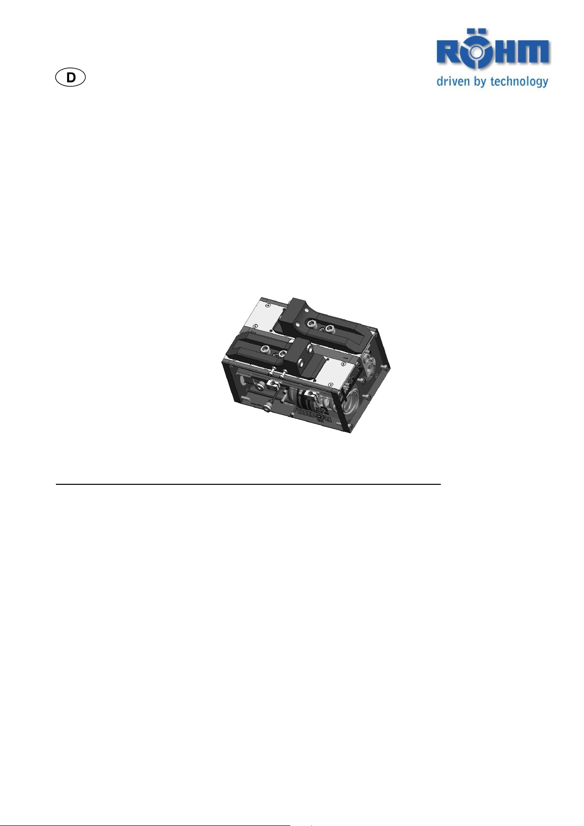
Parallel Long Stroke Gripper
RGP
Description Page
Description of the parallel gripper 2
Safety information and guidelines for use 4
Mounting, Initial operation 7
Servicing, Maintenance 10
Accessories 13
Declaration by the Manufacturer 14
Creation date: Dillingen, 16.01.2014
Id.1140167 Operating Instructions RGP
Röhm-Tool GmbH, Röhmstr. 6, 89407 Dillingen/Donau, GERMANY, Tel. (49)9071/508-0
Page 1 of 14
Page 2
Description of the Parallel Gripper
Parallel Long Stroke Gripper RGP
Id.1140167 Operating Instructions RGP
Röhm-Tool GmbH, Röhmstr. 6, 89407 Dillingen/Donau, GERMANY, Tel. (49)9071/508-0
Page 2 of 14
Page 3

Description of the Parallel Gripper
Parallel Long Stroke Gripper RGP
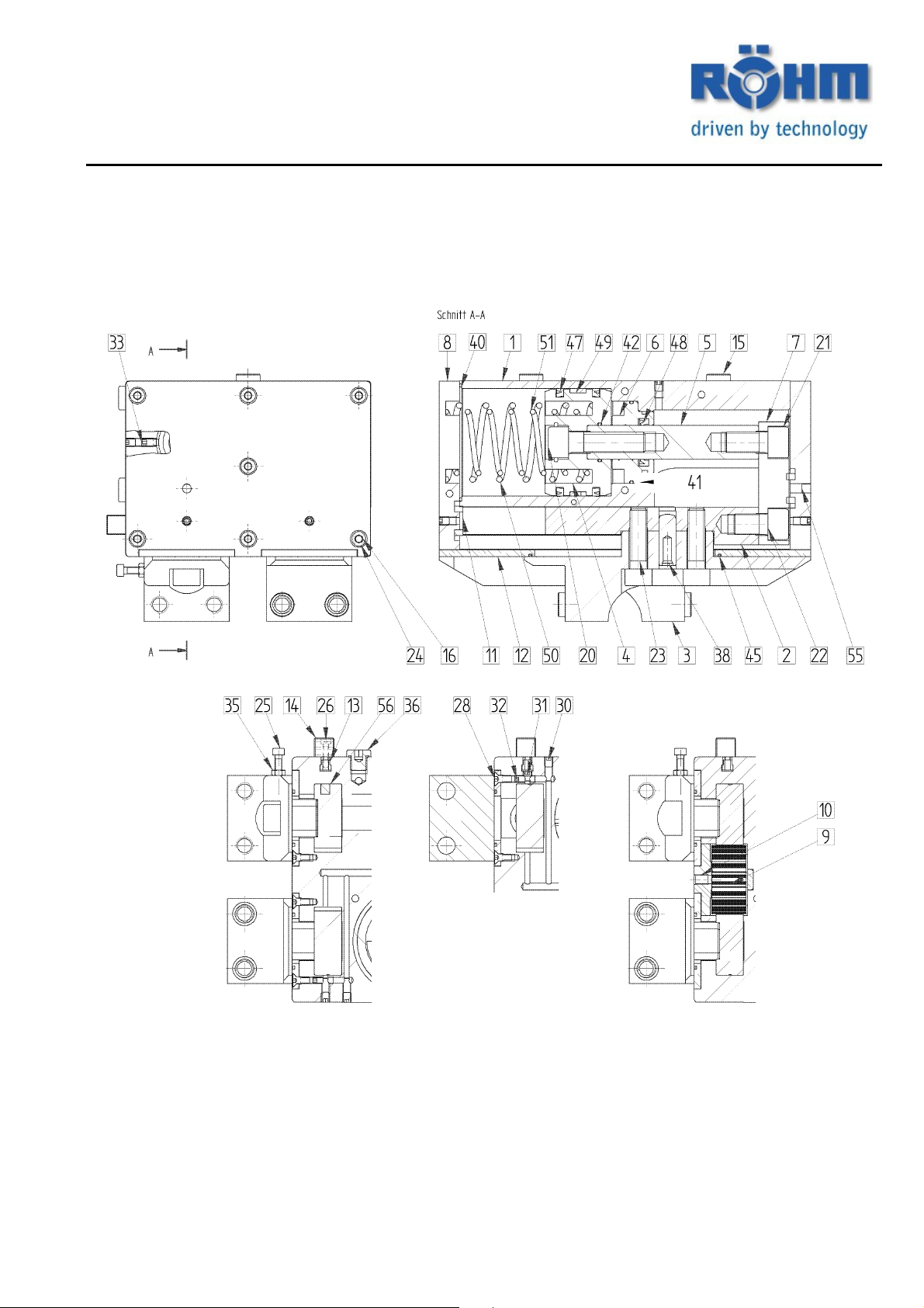
Description Parallel Long Stroke Gripper RGP
Pos. Name Consumable
1 BODY RGP
2 STEERING RACK RGP
3 INTERMEDIATE JAW RGP
4 PISTON DISC RGP
5 PISTON ROD RGP
6 SOCKET RGP
7 CARRIER RGP
8 COVER RGP
9 GEAR WHEEL RGP
10 GEAR WHEEL BEARING RGP
11 DAMPING RING RGP
12 WIPER BLADE RGP
13 SLIDING BLOCK RGP
14 HOLDER
15 CENTERING SLEEVE
16 CENTERING SLEEVE
20 FASTENING SCREW
21 FASTENING SCREW
22 FASTENING SCREW
23 FASTENING SCREW
24 FASTENING SCREW
25 FASTENING SCREW
26 FASTENING SCREW
28 FASTENING SCREW
30 SET SCREW DIN913
31 SET SCREW DIN913
32 SET SCREW DIN913
33 SET SCREW DIN915
35 HEX- NUT DIN934
36 PLUG SCREW EO2
38 CYL-PIN D DIN7979
39 CYL-PIN D DIN7979
40 O-RING x
41 O-RING x
42 O-RING x
43 O-RING x
45 SEALING RING x
47 PISTON SEAL x
48 ROD SEAL x
49 PISTON GUIDE RING SLYDRING x
50 PRESSURE SPRING x
51 PRESSURE SPRING x
55 FILTER DISC
56 ROUND MAGNET
Id.1140167 Operating Instructions RGP
Röhm-Tool GmbH, Röhmstr. 6, 89407 Dillingen/Donau, GERMANY, Tel. (49)9071/508-0
Page 3 of 14
Page 4

Safety information and guidelines for use
Parallel Log Stroke Gripper RGP
I.
Operator qualifications
Persons who have no experience in handling gripping devices run the risk of being injured by the gripping motions and forces occurring as a result of incorrect behaviour, especially during set-up work.
For this reason, gripping devices may be operated, set up or maintained only by persons who have been especially
trained for this purpose and/or have many years of experience
II. Risk of injury
For technical reasons, this assembly may contain individual parts with sharp edges. Always proceed with utmost
caution when working with the assembly to prevent the risk of injury!
1. Built-in stored energy mechanisms
Moving parts which are pre-tensioned by pressure springs, tension springs, other types of spring or by other elastic
elements are a potential danger because of the stored energy they contain. Underestimating the forces associated
with such stored energy may cause severe injuries resulting from components flying about uncontrollably like projectiles. Before any further work can be carried out, these stored energy forces have to be dissipated. Before any
further work can be carried out, these stored energy forces have to be any such sources of danger first by referring
to the relevant assembly drawings.
If it should not be possible to "neutralize" this energy without risk, the dismantling work will have to be carried out by
authorized personnel.
2. Calculating the necessary gripping forces
If this gripping device is to hold or clamp the workpiece against externally applied machining forces, the occurring
machining forces must be determined for a specific machining task and a safety margin must be added, which is
adjusted to the calculation method and machining process. At least these clamping forces, which have been determined in this manner, must then be provided by the gripping device.
3. Use of other/additional clamping inserts/workpieces
The required minimum clamping force must always be calculated for the use of clamping inserts or workpieces.
1. Clamping of other/additional workpieces
If special gripping devices (jaws, clamping inserts, alignment elements, positioning units, points, etc.)
are provided for this clamping equipment, they may be used solely for clamping the workpieces for
which they were designed and in the way for which they were designed. Non-observance of this requirement may result in injury to persons or damage to property as a result of inadequate clamping
forces or unfavourable clamp positioning.
Therefore, before clamping any other or any similar workpieces with the same clamping set, written approval is
required from the manufacturer first.
4. Checking the gripping force
Checking the gripping force (general aspects)
Under Directive EN 1550 § 6.2 No. d) for revolving chucks, which in this one point can also be transferred to stationary clamping equipment, static gripping force measuring equipment should be used at regular intervals to check
the maintenance condition as described in the maintenance instructions. Subsequently, the gripping force has to be
checked after about 40 operating hours – independent of the clamping frequency.
If necessary, special chucking force measuring jaws or devices should be used for the purpose (pressure transducers.
Id.1140167 Operating Instructions RGP
Röhm-Tool GmbH, Röhmstr. 6, 89407 Dillingen/Donau, GERMANY, Tel. (49)9071/508-0
Page 4 of 14
Page 5
Safety information and guidelines for use
Parallel Log Stroke Gripper RGP
5. Stability of the workpiece to be clamped
To ensure that the workpiece can be clamped under the load forces which occur, the clamped material
must be strong enough to withstand the gripping force.
Non-metallic materials such as plastic, rubber, etc. may only be clamped after being tested or with special care!
6. Installing and setting-up work
Clamping movements and, where applicable, setting movements, involve short travel distances under the influence
of what are sometimes powerful forces in short times.
Before carrying out any mounting or setting up work, therefore, the drive units provided for actuating
the gripper must always be switched off first. If, however, the clamping movement is required during
the setting operation, the following instructions must be complied with for clamping travel distances of
over 4 mm:
- The attachment of a permanent or temporary workpiece holding device to the equipment, or
- an independently actuated holding device has to be fitted,
or
-a workpiece loading mechanism is required,
or
- require that the setting work is carried out in hydraulic, pneumatic and/or electric jog mode (corresponding control
must be possible!)
This type of auxiliary setting equipment depends basically on the machining system used and may have to be procured separately.
The machine owner/user is responsible for ensuring that the movement of the clamping equipment does not cause
any danger to persons throughout the entire clamping process. To this end, 2-hand controls for clamp initiation or –
better still – suitable safety equipment should be provided.
7. Fastening and replacing screws
If screws are replaced or loosened, defective replacement or fastening may lead to a hazard for persons and objects. For this reason, the corresponding torque recommended by the manufacturer for the screw and the screw
quality has to be used for all fastening screws as a matter of principle, unless explicitly stated otherwise.
The following tightening torque table applies for the common sizes M5 - M24 of qualities 8.8, 10.9 and 12.9:
Qual. M5 M6 M8 M10 M12 M14 M16 M18 M20 M22 M24
8.8 5,5 9,5 23 46 80 130 190 270 380 510 670 Nm
10.9 8,1 13 33 65 110 180 270 380 530 720 960 Nm
12.9 9,5 16 39 78 140 220 330 450 640 860 1120 Nm
All data in Nm
For this reason, the corresponding torque recommended by the manufacturer for the screw and the screw quality
has to be used for all fastening screws as a matter of principle, unless explicitly stated otherwise.
All fastening screws, which on account of their useful purpose have to be unscrewed and tightened again subsequently (e.g. for refitting work), have to be covered with an anti-seize agent (grease paste) in the thread area and
the head contact area in intervals of six months
Id.1140167 Operating Instructions RGP
Röhm-Tool GmbH, Röhmstr. 6, 89407 Dillingen/Donau, GERMANY, Tel. (49)9071/508-0
Page 5 of 14
Page 6

Safety information and guidelines for use
Parallel Log Stroke Gripper RGP
III. Environmental hazards
The operation of clamping or gripping equipment partly requires the use of various media for lubrication, cooling,
etc. In most cases these media are supplied to the clamping equipment through the hose lines or pipelines. The
most frequently used media are hydraulic fluid, lubricating oil or grease and coolant. When operating the clamping
equipment, these media have to be handled with care so that they do not get into the ground and/or into the water.
Warning: Environmental hazard!
This applies in particular to the following:
For assembly/disassembly as residual amounts may still be in the pipes, piston chambers or oil drain
screws,
To porous, defective or incorrectly fitted seals,
To lubricants which escape from and/or are ejected from the clamping equipment during operation for de-
sign reasons.
For this reason, these escaping substances should be collected and re-used or disposed of in accordance with
applicable regulations.
IV. Safety requirements of power gripping devices:
1. The gripping device must not be allowed to move until the clamping pressure has been reached in the gripper and the clamping force is within the permissible working range.
2. The tension may be relieved only when the gripping device is at a standstill.
3. In the event of the clamping energy failing, a signal has to shut down the machine immediately.
4. In case the clamping energy fails the workpiece has to remain safely gripped.
5. In the event of a power failure and subsequent return of power, no changes of the switch position may occur.
V. Safety information:
1. Do not move any parts by hand if the energy supply is connected.
2. Do not reach into the open mechanism or between the gripping jaws.
3. Disconnect the energy supplied when carrying out any assembly, conversion, maintenance
and setting work.
4. Carry out servicing, conversion and mounting work outside the danger zone.
5. During assembly, connection, setting, commissioning and testing work it must be ensured that
the unit cannot be actuated accidentally by the fitter or other personnel.
6. Protective covers which comply with the EC Machine Directive must be provided when installing all handling modules.
7. Falling or catapulted items may present dangers. Precautions must be taken to prevent items
falling or being catapulted.
8. The care and maintenance intervals must be observed.
9. Grippers which clamp with spring force or have a gripping force guard with springs are springloaded. The springing contact star is also spring-loaded. Therefore special care is required for
dismantling them.
10. Top jaws, particularly on grippers with a gripping force maintenance unit, must be designed in
such a way that a gripper reached one of the limit positions when it is depressurized so that no
residual energy is released when the top jaws are replaced.
Otherwise the maximum working distances must be taken from the relevant tables.
Furthermore, the safety and accident prevention regulations in force at the place of use are also applicable.
Id.1140167 Operating Instructions RGP
Röhm-Tool GmbH, Röhmstr. 6, 89407 Dillingen/Donau, GERMANY, Tel. (49)9071/508-0
Page 6 of 14
Page 7

Mounting, Initial operation of the parallel gripper
Parallel Long Stroke Gripper RGP
Thread holes for mounting the gripper from below Thread holes for mounting the gripper on the sides
M5 for hose-free direct connection M5 both sides for air purge connection G1/8“ for hose connection
(Lubrication connection)
M5 for hose-free direct connection
From below
Hose-free direct connection
Important:
safety information on pages 4-6.
The power supply must be switched off for the gripper assembly. Please also refer to the
Gripper assembly
1. Position the gripper using the two centering sleeves Pos.15, which are supplied in the additional pack.
2. Secure the gripper at the side or from underneath using two screws.
Use the specified tightening torques!
3. For a hose-free direct connection, ensure that the screw-on surface is clean. The relevant
seals from the additional pack must be used for this purpose.
4. For assembly using a compressed air screw connection, ensure that the screw connection is
sealed. When mounting with compressed air connection attention must be paid that the connection is tight.
Important: When using the hose-free direct connections, the grub screws Pos.30 must be removed and the unused connections must be sealed using suitable plug screws Pos.36.
5. Install and adjust the query sensors.
See point: Fitting the inductive proximity switches or magnetic field sensors
Function check
1. Actuate the gripper and check the stroke limit positions of the clamping jaws Pos.2.
2. Check the sensor signal
3. Repeat this process with the workpiece
Id.1140167 Operating Instructions RGP
Röhm-Tool GmbH, Röhmstr. 6, 89407 Dillingen/Donau, GERMANY, Tel. (49)9071/508-0
Page 7 of 14
Page 8

Mounting, Initial operation of the parallel gripper
Parallel Long Stroke Gripper RGP
Proximity switch 1 Proximity switch 2
Sensor screw 1 Sensor screw 2
Fitting the inductive proximity switches
Query: Gripper open
1) Set the gripper to the “OPEN” position
2) Slide the proximity switch 1 as far as possible into the clamp holder 1 Pos.14 up to approx.
0.5mm switching distance between proximity switch and sensor screw 1.
3) Secure the proximity switch in this position by tightening the screw Pos.26.
4) Connect the proximity switch and test its function by closing and opening the gripper. The
proximity switches must be positioned against the sensor screw so that there is no chance of
double signals during closing and opening.
Query: Gripper closed
1) Set the gripper to the “CLOSED” position“
2) Slide the proximity switch 2 into the clamp holder Pos.14 up to approx. 0.5mm switching distance between proximity switch and sensor screw 2.
3) Secure the proximity switch in this position by tightening the screws Pos.26.
4) Connect the proximity switch and test its function by closing and opening the gripper. The
proximity switches must be positioned against the sensor screw in such a way as to ensure
that there is no chance of double signals during closing and opening.
Query: Workpiece gripped
1) Fit the proximity switch with 0,5mm switching distance.
2) Clamp the part you wish to grip.
3) Undo the screws Pos.26, so that the clamp holder Pos.14 can be moved with the proximity
switch. Slide the proximity switch No.1 with internal gripping, resp. No.2 with external gripping.
4) Slide the clamp holder with the proximity switch under the sensor screw until it trips. Proximity switch No. 1 for internal gripping or No. 2 for external gripping.
5) Test the function by actuating the gripper and clamping the part you wish to grip. The proximity switches must be positioned against the sensor screw in such a way as to ensure that
there is no chance of double signals during closing and opening.
Id.1140167 Operating Instructions RGP
Röhm-Tool GmbH, Röhmstr. 6, 89407 Dillingen/Donau, GERMANY, Tel. (49)9071/508-0
Page 8 of 14
Page 9

Mounting, Initial operation of the parallel gripper
Parallel Long Stroke Gripper RGP
Relief cut to insert the
Solenoid switches
Solenoid switch 1 Solenoid switch 2
Fitting the magnetic field sensors
Undo the screws of the factory-mounted clamp holder before mounting the electronic solenoid
switches and slide these together with the slot nuts out of the T-shaped groove through the relief
cut.
Query: Gripper open
1) Set the gripper to the “OPEN” position“
2) Slide the magnetic field sensor 1 through the relief cut into the T-shaped groove until this hits
the cover Pos.8.
3) Secure the solenoid switch in this position by clamping it in the T-shaped groove by tightening the grub screw (max. 0.1 Nm).
4)
Test the function by closing and opening the gripper.
Query: Gripper closed
1) Set the gripper to the “CLOSED” position
2) Slide the magnetic field sensor 2 through the relief cut into the T-shaped groove, until this
reaches its first switching point.
3) Secure the solenoid switch in this position by clamping it in the T-shaped groove by tightening the grub screw (max. 0.1 Nm).
4) Test the function by closing and opening the gripper.
Query: Workpiece gripped
External gripping
1) Clamp the part you wish to grip.
Proceed as described above in points 2 - 4 under >>Gripper closed<< .
Internal gripping
2) Clamp the part you wish to grip.
Proceed as described above in points 2 - 4 under >>Gripper open<<.
Id.1140167 Operating Instructions RGP
Röhm-Tool GmbH, Röhmstr. 6, 89407 Dillingen/Donau, GERMANY, Tel. (49)9071/508-0
Page 9 of 14
Page 10

Servicing, Maintenance of the parallel gripper
Parallel Long Stroke Gripper RGP
Maintenance and service life:
The service condition of the gripper has a critical influence on its operation, clamping force, accuracy
and service life.
The gripper undergoes basic lubrication at the factory using special grease Id.1096752 Klueberplex
BEM 41-132.
Service life for normal use without preventive maintenance: 5 million cycles
Service life for normal use with preventive maintenance: 10 million cycles
Recommendation for preventive maintenance:
For normal use:
Lubrication/Cleaning: Every 2 million cycles or once per year.
For heavy use:
Lubrication/Cleaning: Every 1 million cycles or every six months using the grease nipple.
To be able to lubricate the gripper, a grease nipple must be installed at the central lubrication connection and this
must be used for the lubrication.
The grease nipple can also be positioned where it can be greased best via the direct connections and by using an
adapter plate. One must, however, pay attention that two central lubricating connections on the gripper are fitted
with a separate grease nipple. This ensures that the guides of the steering racks are supplied with lubricant
Note: To achieve optimum lubrication, the start of the lubrication must co-incide with the
open position stage of the gripper.
Although the chuck is sealed hermetically, lubricant may seep out in the case of great internal pressure. This can be
caused by too frequent greasing of the gripper. Seeping lubricant, in particular in the area of the intermediate jaws
indicate over-lubrication.
If the lubricant seeps there every time lubrication is carried out, the lubricating intervals can be omitted for a short
time, resp. can be extended.
Lubricating via the central lubrication:
To retain the function and quality of the gripper it must be lubricated at regular intervals.
Requirement: there are no dosing valves installed in the gripper; the central lubrication must be provided by the
machine manufacturer dosed for each connection.
Lubricant: Lubricating oil VG 220 DIN 51519
Semi-fluid greases of NLGI-classes 000; 00
With a worked penetration of 400-430
Full cleaning with taking the gripper apart approx. every 2000-3000 operating hours.
Basic lubrication: Special grease Id. 1096752 Klueberplex BEN 41-132
Dosing volume of 10 mm3 each per lubricating impulse with 4 impulses per operating hour,
+ with an impulse duration of at least 3 sec.,
+ with an impulse pressure between 12 and 20 bar,
+ with an impulse interval of at least 5 sec.,
+ with an impulse interval pressure of max. 0.8 bar at the input of the dosing valves
+ with a lubricant with ISO designation C GLP 68 DIN 51502 or with viscosity class VG 220 DIN 51519
OGEL
triggered (these data apply to V
dosing units)
Id.1140167 Operating Instructions RGP
Röhm-Tool GmbH, Röhmstr. 6, 89407 Dillingen/Donau, GERMANY, Tel. (49)9071/508-0
Page 10 of 14
Page 11

Servicing, Maintenance of the parallel gripper
Parallel Long Stroke Gripper RGP
The steering rack guides are thereby supplied with lubricant.
Note: To achieve optimum lubrication, the start of the lubrication impulses must co-
incide with the open position stage of the gripper.
Although the chuck is sealed hermetically, lubricant may seep out in the case of great internal pressure. This can be
caused by continuously added, unconsumed lubricant. Seeping quantities of lubricant, in particular in the area of the
intermediate jaws indicate over-lubrication.
If the lubricant seeps there every time the central lubrication is activated, the lubricating impulses can be interrupted
for the duration of an 8-hour shift.
Dismantling and assembling a gripper:
Important: It is essential that you observe the safety information
1) Remove the pressure lines
2) Undo the screws Pos.23, dismantle the cylinder pin Pos.38. Now you can remove the intermediate jaw.
3) Remove the screws Pos.28, dismantle the cylinder pin Pos.39. The wiper blade Pos.12 can then be removed. Remove the sealing ring Pos.45.
4) Remove the screws Pos.24 and remove the cover Pos.8.
5) Undo the screw Pos.21 and remove it. The piston disc Pos.4 can now be removed rearwards, together with
the piston rod Pos.5. The steering rack Pos. 2 together with the carrier Pos.7 can also be pulled forwards
out of the guide. Careful! The steering rack on the other side is switched co-rotating to the centre via a gear
wheel Pos. 9 (pay attention to the positions of the steering rack)
6) Pull the gear wheel bearing Pos.10 from the body Pos. 1 with the help of a pin package. The gear wheel
can be removed.
7) Turn the set screw Pos.33 back by about 3mm and remove the sockets Pos.6 from the body Pos.1.
8) Remove all the seals
9) Clean all the parts thoroughly and check the parts for signs of wear or defects
10) Replace all the seals
The assembly process is the same as above but in reverse.
Pay special attention to the numbering and position of the components. Unless specified to the contrary all the
screws are to be secured using Loctite 222 and tightened with the torque specified in DIN standards (see point II/7).
.
Version GA resp. GI with gripping force safety device:
Attention!
The cover Pos.8 with GA version and the piston disc Pos.4 with GI version can be subject to spring tension. This
presents special dangers.
Please always refer to the assembly drawing.
When dismantling the cover Pos.8 the spring tension (approx. 210N) must be counteracted by suitable
measures. (Clamping into a vice, then undoing the screws).
When dismantling the piston disc Pos.4 the spring tension (approx. 210N) must be counteracted by an auxiliary device.
Id.1140167 Operating Instructions RGP
Röhm-Tool GmbH, Röhmstr. 6, 89407 Dillingen/Donau, GERMANY, Tel. (49)9071/508-0
Page 11 of 14
Page 12

Servicing, Maintenance of the parallel gripper
Parallel Long Stroke Gripper RGP
Servicing:
Most of the servicing work is required at very large intervals (approx. every 5 million cycles). However, at
the latest when it starts to become difficult to move the gripper and the clamping force drops, take the
gripper off the machine and clean it thoroughly.
To do so, dismantle the gripper down to its individual parts and check the parts for wear. Clean the parts
and reassemble after having repaired any defective parts and relubricate it with special grease. It is advisable to replace the dynamically loaded sealing elements. For this reason, a set of the wearing parts
and sealing elements marked in the parts list should be available for such a case.
When assembling the gripper, take care to ensure that the marked parts are placed back in the intended
position.
Please be advised that only ORIGINAL spare parts or parts from authorised suppliers authorized may be
used. Any liability shall cease to exist for all damage caused by the use of foreign components.
Important: In order to be able to handle any orders of spare parts or individu-
al parts easily, the six-digit identification number engraved in the
component and the manufacturing number - if available - have to
be stated. The manufacturing number consists of two digits and a
consecutive number, attached to the identification plate or in the
direct vicinity of the identification number.
Address of the manufacturer: Firma
R
Röhmstr. 6
89407 Dillingen/Donau
GERMANY
ÖHM
GmbH
Id.1140167 Operating Instructions RGP
Röhm-Tool GmbH, Röhmstr. 6, 89407 Dillingen/Donau, GERMANY, Tel. (49)9071/508-0
Page 12 of 14
Page 13

Declaration by the manufacturer
Parallel Long Stroke Gripper RGP
Inductive proximity switch
Order No. Id.229114
With 3m cable (without plug)
30,5
Magnetic field sensor
Order No. Id.1132737
With 5m cable (without plug)
6,2
29
Compressed air connection Throttle non-return valve
Order No. Id.477025 Order No. Id.499260
G1/8"
8
Plug connector
Order No. Id.1111010
G1/8"
4,6
Pressure loss prevention valve
Order No. Id.1078823
M8 x 1
3,2
5
4,4
6
6
O
G1/8"
4,9
6
O
O
60
36
M5
32,2
6,1 20
22
Id.1140167 Operating Instructions RGP
Röhm-Tool GmbH, Röhmstr. 6, 89407 Dillingen/Donau, GERMANY, Tel. (49)9071/508-0
18,2
4,4
4,5
O
G1/8 (4x)
8
O
1:1
Page 13 of 14
Page 14

Declaration by the manufacturer
Parallel Long Stroke Gripper RGP
Id.1140167 Operating Instructions RGP
Röhm-Tool GmbH, Röhmstr. 6, 89407 Dillingen/Donau, GERMANY, Tel. (49)9071/508-0
Page 14 of 14
 Loading...