

查询RCM1583U-A供应商
RCM1583U-A
Liquid crystal displays
MOSAIC DISPLAY UNIT
RCM1583U-A
Thanks to the high contrast and wide viewing angle of the RCM1583U-A, which is provided by its unique design
technology, this module brings forth new applications in brand new LCD fields. ROHM large-sized LCD units are perfect
displays for information or sign boards. As a media for informational display, large-sized LCD units must possess high
visibility, wide viewing angles, and other such superior qualities. ROHM large-sized LCDs boast an excellent track record
and possess guaranteed functionality for assured satisfaction in a variety of situations.
Applications
!!!!
Indoor information board (airport, train station, bus depot), In-hall or in-store display, public message board.
Features
!!!!
1) Most suitable for the alphabet and number display.
2) Wide viewing angle and high contrast.
3) Compact and light weight for easy assembly.
4) Low power consumption.
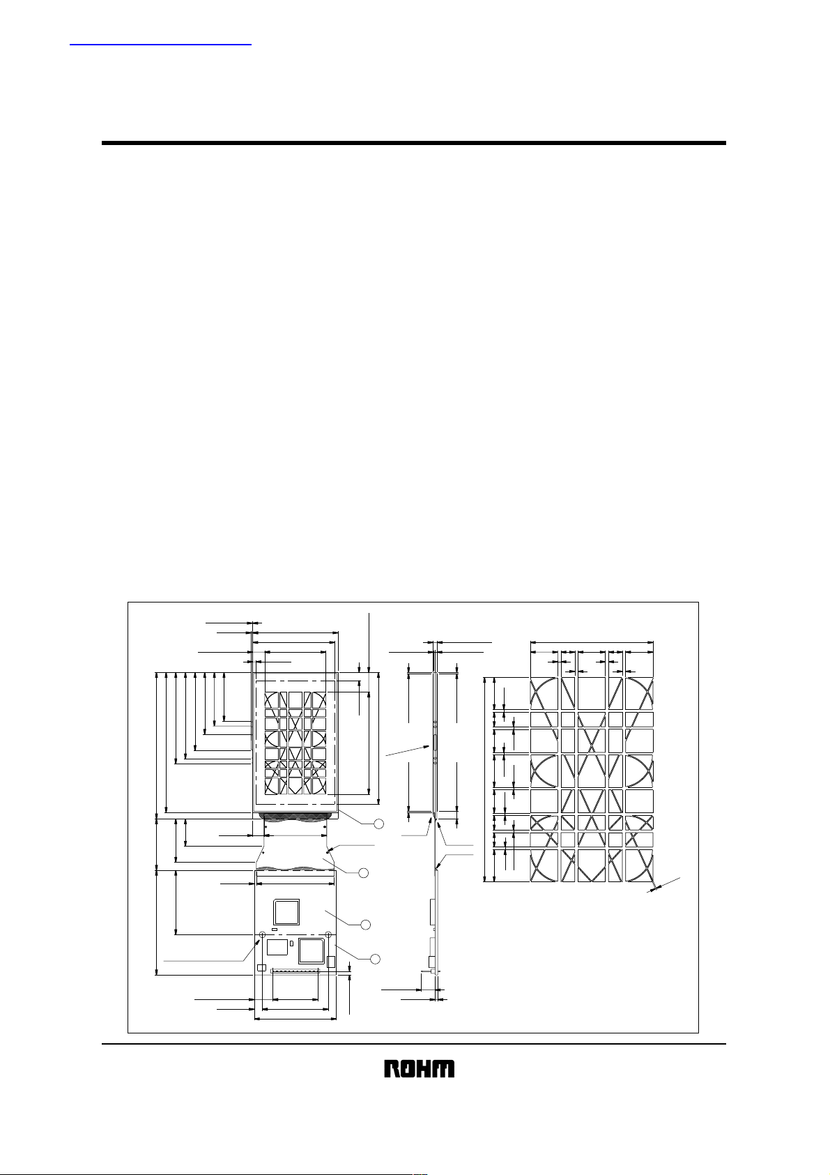
External dimensions
!!!!
48.5Max.
53.75Max.
56.75Max.
(87.0)
91.0±0.3
(17)
−1.0
+1.5
(27)
32
(Units : mm)
0.3Max.
1Max.
7.45±0.3
30.25Min.
33.25Min.
38.5Min.
(7.0) 39.0±0.3
(1.3)
2Max.
53.0±0.3
51Min.
(38.1)
48.4±0.3
5Max.
4−Hole
2
12.17±0.3(63.5)
82Min.
1.1±0.1
VIEWING ANGLE
1
0.7±0.7
(6:00)
0.7±0.7
UV REGIN
2.75±0.3
1.1±0.1
0.7±0.7
4.7±0.7
UV REGIN
UV REGIN
63.5
38.1
4.3
8.5
4.3
8.5
1
1
0.8
4.5
7.2
0.8
0.8
10 10
0.8
0.80.8
7.24.54.5
0.8
10
8.5
1
1
0.3
(40)
(2.27)
3
4
(8.54)
(1.6)
65.0±0.5
+0.15
2−φ3.96
Hole
−0
11.53±0.5
5±0.5 41±0.1
12
(P2.54×11)
27.94
51±0.5
1
Liquid crystal displays
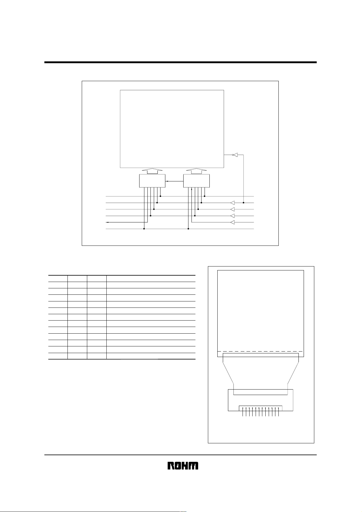
Block diagram
!!!!
RCM1583U-A
MOSAIC
105 SEGMENT
LCD
80 CHANNEL
12
V
DD
11
M
10
CL1
9
CL2
8
DO
7
GND
OUTPUT
Pin functions
!!!!
(1) Input (CN1)
VDD
M
CL1
CL2
DI
GND
GND
DO
CL2
CL1
M
V
IN / OUT
Charge 5Volt
−
Alternating signal of LCD operating output
IN
Data latch signal (display at descending edge)
IN
IN
Shift resistor signal (displayed at descending edge)
IN
Display data signal (1: Lighting 0: Non-Lighting)
−
Ground electric potential
−
Ground electric potential
OUT
Display data signal
OUT
Shift resistor signal
OUT
Data latch signal
OUT
Alternating signal
−
DD
5Volt
Pin No. Symbol Function
1
2
3
4
5
6
7
8
9
10
11
12
LCD Driver
with
Outputs
LCD Driver
with
80 CHANNEL
Outputs
1
V
DD
2
M
3
CL1
4
CL2
5
DI
6
GND
INPUT
Pin
!!!!
LCD
MV
CC
012
OUTPUT
FPC
PCB
LLDDO
21D
DCGG
LINN
2DD
INPUT
VM
C
L
D
1
D
1325769111 8 4
No
Liquid crystal displays
Absolute maximum ratings
!!!!
Parameter Symbol Limits Unit
Power supply
voltage
Input voltage
Operating temperature
Storage temperature
Electrical characteristics
!!!!
Circuit
LCD operation
(VDD = 5.0V, GND = 0V, Ta = 25°C)
(Ta = 25°C)
DD
V
VDD−V
V
IN
Topr
Tstg
RCM1583U-A
−0.3 ~ +7.0
EE
−0.3 ~ +7.0
−0.3 ~
VDD+0.3
−20 ~ +70
−40 ~ +85
V
V
V
°C
°C
Parameter
Input high level voltage
Input low level voltage
Output high level voltage
Output low level voltage
Input LCD voltage
Comsumpting current
AC characteristics
!!!!
Parameter
Data shift flequency
Clock high level width
Clock low level width
Data setup time
Clock setup time 1
Clock setup time 2
Data hold time
Clock rise / fall time
Output delay time
Alternating signal
Symbol Min. Typ. Max. Unit Conditions
V
IH
V
IL
OH
V
V
OL
VLCD
I
DD
0.8V
DD
V
−
−0.4
−
−
−
−
DD
−
−
−
5.0
−
V
0.2V
0.4
6.0
DD
−
−
V
V
DD
OH
= −0.4mA
I
V
OL
= +0.4mA
I
V
V
mA
f
CL
= 1MHz, fM = 100Hz
(VDD = 5.0V, GND = 0V, Ta = 25°C)
Symbol
CL
f
tCWH
CWL
t
tSU
tSL
tLS
tDH
tct
tpd
M
f
Applicable terminal
CL2
CL1, CL2
CL2
DI
CL2
CL1
DI
CL1, CL2
DO
M
Min.
−
470
470
120
220
220
120
−
−
50
Typ.
−
−
−
−
−
−
−
−
−
100
Max.
1
−
−
−
−
−
−
50
250
150
Unit
MHz
ns
ns
ns
ns
ns
ns
ns
ns
Hz
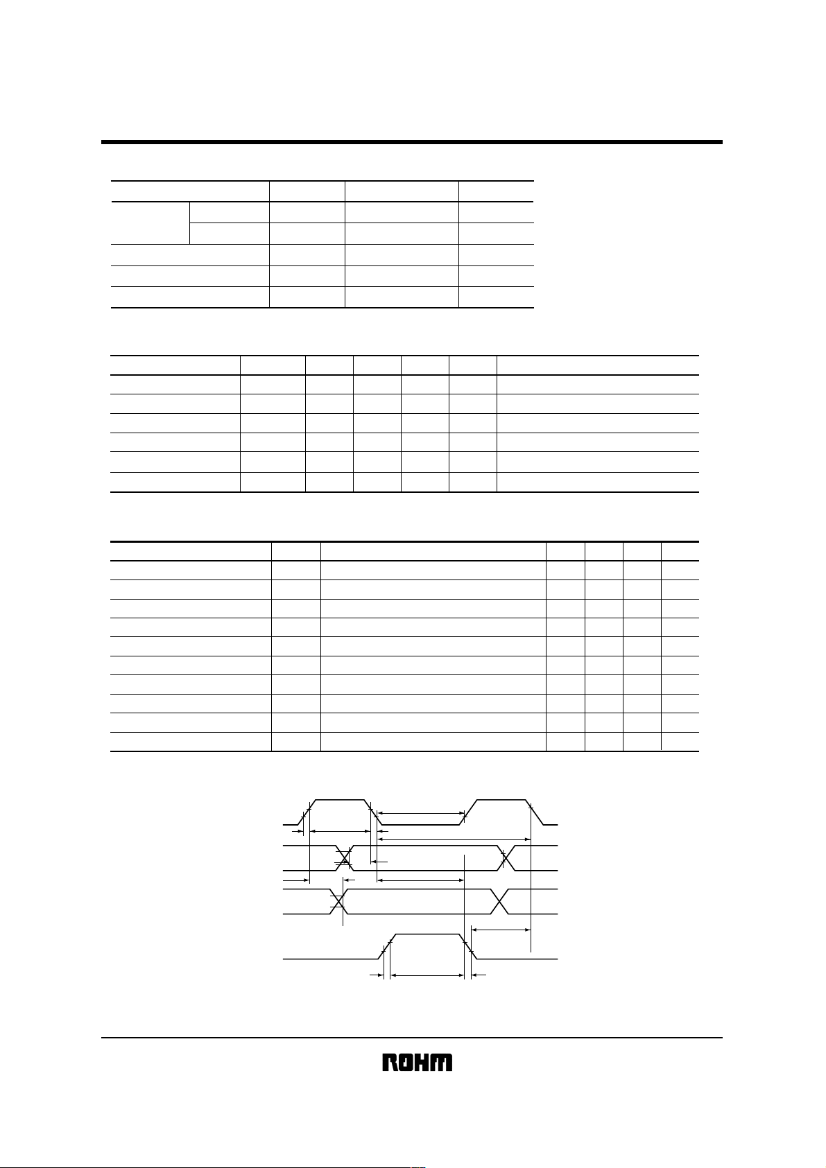
Timing characteristics
!!!!
CL2
DI
DO
CL1
V
V
IH
V
IL
t
ct
t
pd
t
CWH
V
IH
V
IL
V
OH
V
OL
V
V
iL
t
t
CWL
t
ct
t
SU
IH
ct
Fig.1
t
DH
t
SL
t
CWH
IH
t
LS
t
ct

Liquid crystal displays
Optical characteristics
!!!!
(Ta = 25°C)
RCM1583U-A
1
2
3
ParameterNo.
Response time
Viewing Range
Contrast ratio
Symbol
Vertical
horizontal
Tr
Td
θ
φ
K
Temperature (°C)
25
25
25
25
25
(Note 1) Driving pulse
Static drive
V
op
0
-V
op
1 / f
f = Frequency
(Note 2) Response time definition and condition
OFFON
I
OFF
I
0.91
I
ON
T
r
d
T
T
0.11
Tr : The time required to activate from non-selecting
wave pattern to selecting wave pattern and to change
90% for darken.
φ = 180°, θ = 10
°
Td : The time required to activate from selecting wave
pattern to non-selecting wave pattern and to change
90% for darken.
φ = 180°, θ = 10
°
Typ. Max.
Min.
400
90
35
−
−
65
−
150
−
45
−
0
−
50
0
0
Unit
800
100
ms
300
100
60
deg
270
−−
Note
(Note 2)
(Note 3)
K≥3
φ = 180°, θ = 10°
(1) φ : Angle which an obsever will become Z Z’.
(2) θ : When obsevers position is consideres as flat X,Y
over a projector angle which makes Y Y’.
(3) Greatest viewing angle derection : Time axis which
represent best contrast ratio.
(Note 4) Definition of contrast ratio
<Definition
>
Luminous intensity at off
n
segment transmissivity
Contrast ratio =
Luminous intensity at on
segment transmissivity
Positive type n = 1, Negative type n = -1
<Measurement conditions
>
Drive conditions: Specific value condition
Viewing angle: φ = 180°, θ = 10
°
(Note 5) Optical measuring equipment theory plan
Inspecting
Light source
material
Measuring Light
Specific measuring
equipment
LC−4M
(Note 3) Definition of viewing angle (φ, θ)
Z (θ = 0°)
Viewing angle 12:00
Y (φ = 0°)
X'
(φ = 90°)
θ
2
1
θ
X
(φ = 270°)
Y' (φ = 180°)
Viewing angle 6:00
Thermostat

Liquid crystal displays
Data format
!!!!
(data and display mapping)
RCM1583U-A
105
103
100
99
1
4
102
98
104
101
89
88
95
96 91
97
94
93
92
90
86
12
13
14
15
16
20
5
11
6
10
7
9
2
8
3
18
17
21
FIRST DATA
D1 D2 D3 D103 D104 D105 D106 D107 D159 D160
23
25
30
49
48
47
82
24
28
29
56
50
51
52
53 54
78
77 76
53
58
22
27
31
32
33
36
38
39
40
19
26
34
44
43
35
42
45
37
46
41
83
87
80
81
62
63
64
61
57
66
60
59
85
84
79
75
74
72
73
71
70
65
69
68
67
effective data invalid data
LAST DATA

Liquid crystal displays
Timing chart
!!!!
M
CL1
CL1
CL2
DATA
RCM1583U-A
f
M
f
CL
SEG
COM
Note) LCD operation output voltage
M DATA SEG Voltage
1
1
0
0
1
0
1
0
COM Voltage
GND
GND
V
DD
V
DD
DD
V
GND
GND
DD
V

RCM1583U-A
Liquid crystal displays
Operation notes
!!!!
(1) Handling instruction
••••
Attention must be paid to avoid external shock, which will cause operational failure.
••••
Polarizer on the surface is gentle and can be damaged easily by scratch, thus please take extra care when handling.
For surface termination, please wipe off with alcohol.
••••
The liquid used in the LCD panel is a harmful substance and must not be licked or awallowed. If you touch this liquid,
wash it out completely.
••••
Do not touch IC lead and terminal.
••••
Do not expose to direct sunlight for a long period of time and if it will be used at direct sunlight, recommend to use
UV cut filter.
••••
For storage please avoid in high temperature, high humidity. When long-term storage is required, keep the panels in
low temperature (5°C ∼ 25°C) and low humidity.
••••
To prevent TAB damage, TAB bent time must be up to twice.
(2) Operational instruction
••••
Please do not connect or take away the LCD module to the system in the condition of power on.
••••
Please input signal after LCD module power is turned on when turning off. Please turn off from input signal. In worst
case IC can be broken by ratch up phenomenon.
(3) Mounting instruction
••••
In the circuit CMOS-IC is used. Please be careful for ESD.
••••
Protection sheet is put on LCD module surface and back side. At removing the sheet, electric static is generated. So
it must be removed slowly and recommend to use Ion blower etc.
(4) Cautions for LCD with FPC
••••
Do not pend nor pull FPC.
••••
Do not hold FPC with fingers directly nor suspend FPC.
••••
When bending FPC, keep 5mm from the edge of grass (FPC joint) and bend toward mother board side.
(5) Production
••••
Production in Japan or China.
 Loading...