

Page 1

RCM1277U-A
Liquid crystal displays
16 x 16 dots transmissive large-sized
liquid crystal display unit
RCM1277U-A
Thanks to the high contrast and wide viewing angle of the RCM1277U-A, which is provided by its unique design
technology, this module brings forth new applications in brand new LCD fields. ROHM large-sized LCD units are perfect
displays for information or sign boards. As a media for informational display, large-sized LCD units must possess high
visibility, wide viewing angles, and other such superior qualities. ROHM large-sized LCDs boast an excellent track record
and possess guaranteed functionality for assured satisfaction in a variety of situations.
Applications
!
Public displays such as airport displays,
train station displays, information
boards, and billboards.
Features
!
1) Wide viewing angle, high contrast,
and fast response.
2) Compact and light weight for easy
assembly.
3) Supports negative or positive display.
4) Low power consumption.
External dimensions
!
1Max.
0.3Max.
2.515±0.3
2Max.
20.75Min.
23.75Min.
33.75Max.
36.75Max.
0.3
0.3
±
±
61
57.5
0.3
(8)
±
(3.5)
(15.5)(4)
0.3 4
0.5
±
±
27
35
CN2 CN1
8181
23±0.3
Please specify the viewing direction
(Units : mm)
56±0.3
54Min.
50.97±0.1
2 to 2.8 dia.
46±0.5
2Max.
1.1±0.11.1±0.1
]
64.7
[
Viewing
direction
6:00
[
[R3.2]
]
2.52
30.2
Dots details
2.65±0.3
0.71
C0.1
[40.5]
0.51.0
±
2.7
0.3
±
0.351
±
2.5
0.2
±
54Min.
Page 2

Liquid crystal displays
Block diagram
!
LCD
COM. 1
RCM1277U-A
COM. 2
Pin functions
!
64 output
driver IC
FLM
V
DD
V
O
M
CL1
CL2
DO
GND
OUTPUT INPUT
64 output
driver IC
(1) Input (CN1)
Pin no. Symbol Function
1
2
FLM
V
3V
4MIN
5 CL1 IN
6 CL2 IN
7DIIN
8 GND -
IN / OUT
IN
O
DD
Frame start code
-
Liquid crystal drive power supply
-
Applies 5 V
Liquid crystal drive output AC conversion signal
Data latch signal (displays at rising edge)
Shift register shift signal (reads data at falling edge)
Display data signal (1: On, 0: Off)
Ground
COM waveform
generator circuit
FLM
V
DD
V
O
M
CL1
CL2
DI
GND
(2) Output (CN2)
Pin no. Symbol
1
2
3 CL2 OUT
4 CL1 OUT
5 M OUT
6V
7V
8 FLM OUT
GND
DO
DD
O
IN / OUT
-
OUT
-
-
Function
Ground
Display data code
Shift lock signal
Data latch signal
AC conversion signal
5 V
Liquid crystal drive power supply
Frame start signal
Page 3

Liquid crystal displays
Absolute maximum ratings
!
Parameter
Logic power supply voltage
LCD drive voltage
Input voltage
Operating temperature
Storage temperature
Electrical characteristics
!
Parameter
Input high level voltage
Input low level voltage
Output high level voltage
Output low level voltage
Power supply current
AC characteristics
!
Parameter
Shift frequency
High level lock width
Low level lock width
Data setup time
Clock setup time 1
Clock setup time 2
Data hold time
Clock rise / fall time
FLM setup time
FLM hold time
Output delay time
AC conversion signal
(VDD = 5.0V ± 0.25V, Ta = 25°C)
Symbol Min. Typ. Max. Unit Conditions
(VDD = 5.0V ± GND = 0V, Ta = 25°C)
(Ta = 25°C)
Symbol Limics Unit
V
V
V
IH
V
IL
OH
V
V
OL
I
DD
DD
DD-VO
IN
V
Topr
Tstg
Symbol
f
CL
t
CWH
CWL
t
t
SU
t
SL
t
LS
t
DH
t
t
FDS
t
FDH
t
pd
f
3.5
4.6
ct
M
−0.3~+7.0 V
−0.3~+7.0
DD
−0.3~V
0~+50
−10~+60
-
-
-
-
-
-
-
-
Applicable terminal
+0.3
-
1.5
-
0.4
6.0
CL2
CL1, CL2
CL2
DI
CL2
CL1
DI
CL1, CL2
FLM
FLM
DO
M
V
V
V
V
mA
V
V
°C
°C
OH
−I
I
OL
= +0.4mA
CL
= 1MHz, fM = 70Hz
f
= −0.4mA
Min.
470
470
120
220
220
120
120
120
RCM1277U-A
Max.
Typ.
1
-
-
-
-
-
-
-
-
-
-
-
-
-
-
-
-
50
-
-
-
-
-
-70250-ns
-
Unit
MHz
ns
ns
ns
ns
ns
ns
ns
ns
ns
Hz
Timing characteristics
!
CL2
DI
DO
CL1
FLM
V
V
IH
V
IL
t
t
ct
CWH
V
IH
t
SU
V
IL
t
pd
V
OH
V
OL
V
V
t
ct
V
IH
t
CWL
t
ct
IH
iL
Fig.1
t
DH
t
SL
t
CWH
t
FDS
IH
t
LS
t
ct
t
FDH
Page 4
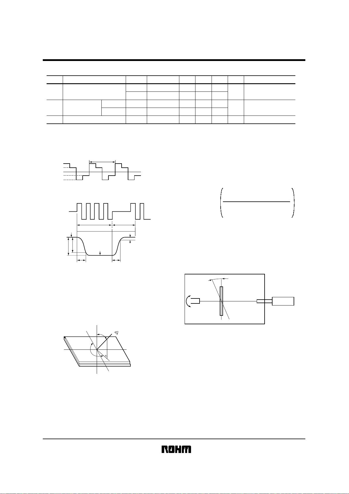
Liquid crystal displays
Optical characteristics
!
ParameterNO.
Response speed
1
Viewing angle
2
3
Contrast ratio
(Ta = 25°C)
Front-back
Right-left
Symbol
Tr
Td
θ
φ
Temperature (°C)
25
25
25
25
25
Min.
-
-
0
90
20
Typ. Max.
65
130
45
100
-
60
-
270
-
--
Unit
ms
deg
RCM1277U-A
Note
(Note 2)
(Note 3)
K≥3
(Note 4)
(Note 1) Drive waveform
Static drive
1 / f
f = Frequency
1 / 2V
-1 / 2V
V
op
op
0
op
-V
op
(Note 2) Definition of response speed
OFFON
I
OFF
I
0.91
T
I
ON
r
d
T
T
0.11
Tr : Time for segment to darken 90% after selective
Waveform switches to non-selective waveform.
φ = 180°, θ = 10
°
Td : Time for segment to darken 90% after selective
Waveform switches to non-selective waveform.
φ = 180°, θ = 10
°
(Note 3) Definition of viewing angle (φ, θ)
Y (φ = 0°)
Z
θ
Observer
(3) Maximum viewing angle: The direction with highest
contrast expressed at the time axis (refer to above
table).
(Note 4) Definition of contrast ratio
<Definition
>
Luminance during application
Contrast ratio =
of non-selective waveform
Luminance during application
of selective waveform
Except, n = 1 with positive display and n = -1 with
negative display.
<Measurement conditions
>
Drive conditions: As per specifications
Viewing angle: φ = 180°, θ = 10
°
(Note 5) Principles of optical measuring equipment
Illumination
Constant temperature chamber
Specimen
Photometry
Characteristic measuring
device
LC-4M
n
X (φ = 90°)
LCD
φ
Z'
Y' (φ = 180°)
X' (φ = 270°)
(1) φ : Angle subtended by the Y-Y’-axis and the
observer’s position projected onto the XY-plane.
(2) θ : Angle subtended by observer and the normal
Z-Z’-axis (X-axis and Y-axis are positive)
Page 5
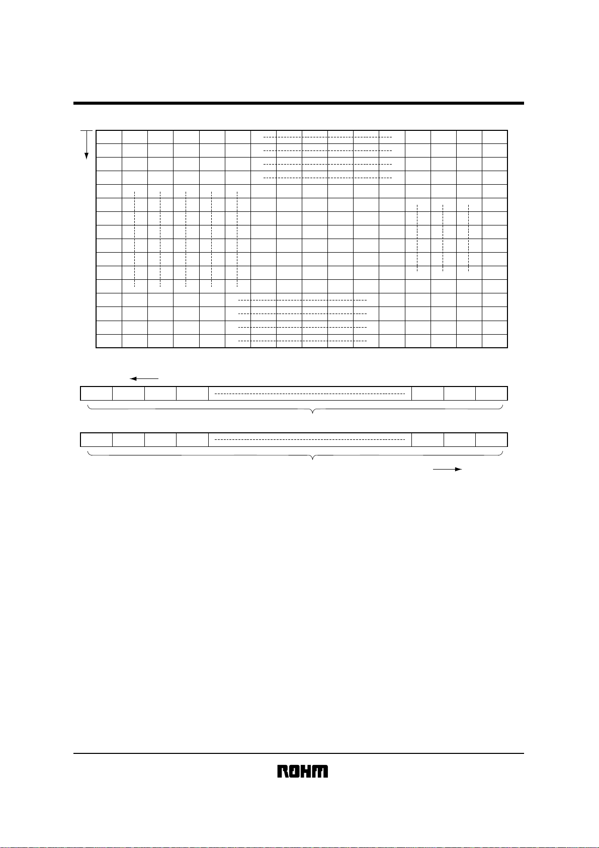
Liquid crystal displays
Data format
!
(data and display mapping)
D1
D17
D33
D2
D18
D34
D3
D19
D35
D4
D20
D36
D5
D6
D7
D8
D9
D10
D11
D12
D13
D29
D45
D14
D30
D46
D15
D31
D47
D16
D32
D48
D49
D50
D51
D52
D61
D62
D63
D64
D65
D66
D67
D68
D77
D78
D79
D80
D81
D82
D83
D84
D188
D189
D190
D191
D192
RCM1277U-A
D193
D209
D225
D194
D210
D226
D195
D211
D227
D196
D212
D228
D197
D213
D229
D204
D220
D236
D205
D221
D237
D206
D222
D238
D207
D223
D239
D208
D224
D240
D241
D242
D243
D244
D245
D246
D247
D248
D249
D250
D251
D252
D253
D254
D255
D256
FIRST DATA
D2
D4 D6 D8 D252 D254 D256
COM.2 DATA
D1 D3 D5 D7 D251 D253 D255
COM.1 DATA
LAST DATA
Page 6
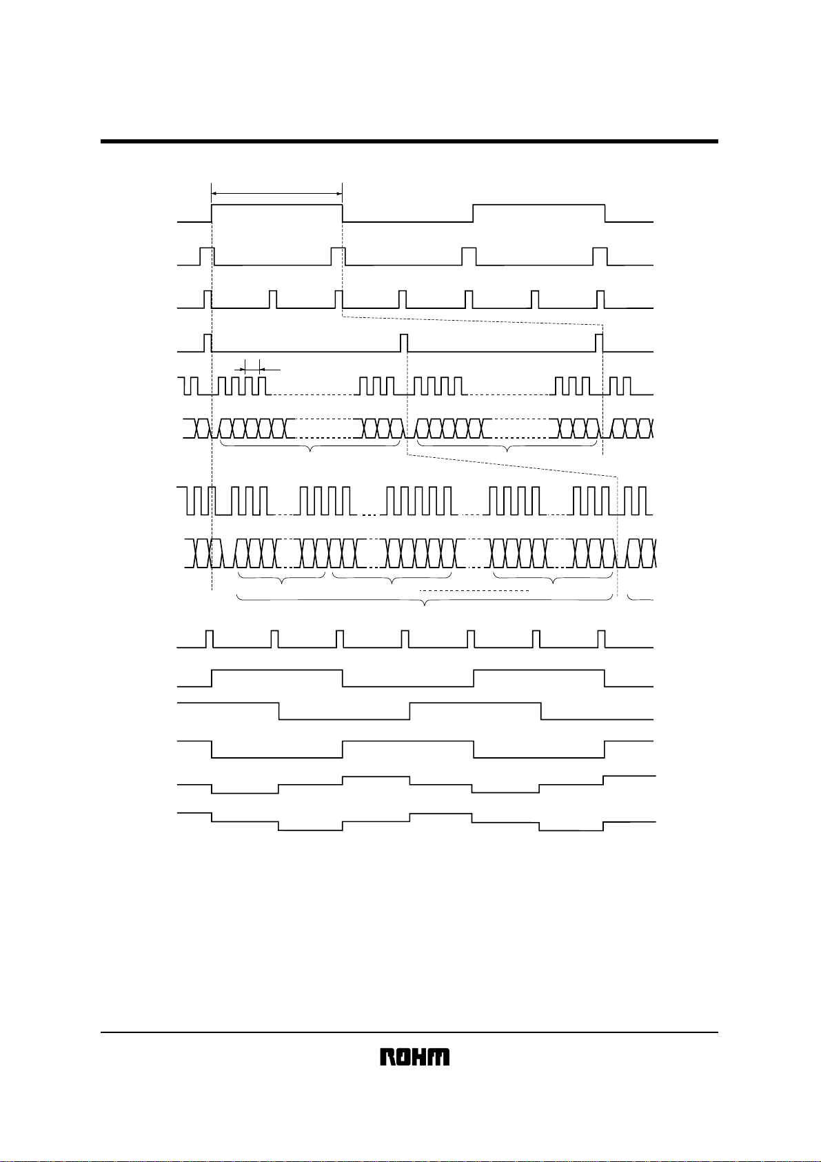
Liquid crystal displays
Timing chart
!
M
FLM
CL1
RCM1277U-A
f
M
CL1
CL1
DATA
CL2
DATA
CL1
SEG.
(ON / ON)
SEG.
(ON / OFF)
SEG
(OFF / OFF)
D2 D4 D6
f
CL
COM.2 DATA
No. 1 panel
COM.1 DATA
254 256
D2 D4 D6D4D2 D8 D1 D3
248 250252 254256 254 256 258
No. 2 panel
COM.2 DATA COM.1 DATA
No. n panel
COM.1
COM.2
Page 7

Liquid crystal displays
Operation notes
!
(1) Attention points in handling
••••
Protect the module from strong shocks as they can
cause damage or defective operation.
••••
The polarizing plate on the surface of the module is
soft and can easily be scratched. Wipe away dirt and
dust using an alcohol-based cleanser.
••••
If the liquid crystal panel is damaged and liquid crystal
contacts your clothing or body, wash immediately with
soap and water.
••••
Do not touch the IC lead electrodes or the electrode ter minal components.
••••
If the module is to be used for long periods subjected
to direct sunlight, employ a filter to block the ultraviolet
rays.
••••
Do not store the module in areas of high temperature
or high humidity. Do not store the module in locations
exposed to direct sunlight or fluorescent light.
••••
During handling of the module, in order to prevent
damage to the tab, do not bend it more than two times.
(2) Precautions during operation
••••
Do not connect or disconnect the module while the
power supply is turned on.
••••
Input the input signal after the module power supply is
turned on. When turning it off, turn off the input signal
first. Otherwise the IC may be damaged by the latch up phenomenon.
(3) Precautions during installation
••••
Be careful to avoid damage from static electricity. A
CMOS-IC is used in the modules circuitry that can be
easily damaged by static electricity.
••••
A protective film is pasted over the front and back of
the module to protect the panel surfaces. When peel ing this film off, be sure to peel as slow as possible in
order to minimize the generation of static electricity.
Use of a ion blower or other deionizing device is rec ommended.
RCM1277U-A
 Loading...