

Page 1
Bedienungsanleitung für
Operating Instructions for
Instructions de service pour
Instrucciones de servicio para
Istruzioni per l‘uso
D
GB
F
E
I
RN 1059
Backen-Ausdrehvorrichtung BAV Typ 091
Jaw Cutting Attachment BAV Type 091
Dispositif BAV – Type 091 pour le tournage
des mors au tour
Dispositivo para mecanizar y rectifi car de
garras BAV tipo 091
Dispositivo di tornitura griffe BAV – Tipo 091
Stand: 09/06
Page 2
D
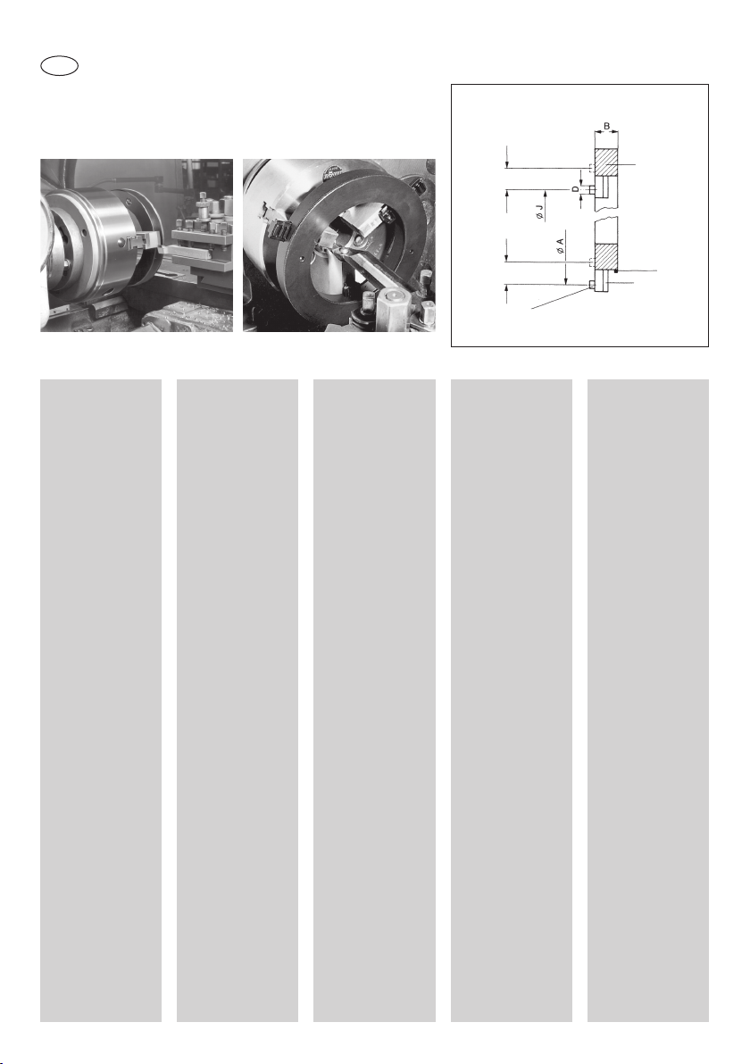
Backen-Ausdrehvorrichtung BAV Typ 091
Einhängebereich
Backenstellung
normal
Gehäuse
mit Spiralring
Außen-Überdrehen
ungehärteter Backen
Verwendungszweck
Die Ausdreh-Vorrichtung BAV fi ndet
vorwiegend Verwendung beim Innen-
Ausdrehen und
Außen-Überdrehen
weicher Backen an
Dreibackenfuttern.
Mit ihrer Hilfe
kann das Futter in
wenigen Sekunden
in den Zustand
versetzt werden,
den es bei späterer
Werkstückbearbeitung einnimmt
(Vorspannung).
Die angedrehten
Spannfl ächen
der Futterbacken
sind damit im gespannten Zustand
formschlüssig und
genau konzentrisch.
2
Innen-Ausdrehen
ungehärteter Backen
Anwendungsbereiche
a) Ausdrehen
von ungehärteten
Aufsatzbacken
b) Ausdrehen von
unhegärteten Blockbacken
(Hierzu Hinweise
beachten)
c) Ausschleifen von
gehärteten Aufsatzbacken
(Hierzu Hinweise
beachten)
KonstruktionsMerkmale
In einem kräftigen
Gehäuse wird ein geschmiedeter Spiralring über ein Rändel
von Hand gedreht.
Diese Spirale bewegt
3 Einstellbacken,
an denen je eine
Einhängeschraube
angebracht ist, nach
innen oder außen.
Die Einstellbacken
sind umkehrbar.
Rändelring nach
rechts gedreht,
verkleinert den Einhänge-Ø, Rändelring
nach links gedreht,
vergrößert den
Einhänge-Ø.
Einhängebereich
Einhängeschrauben
Anwendung
a) Innen-Ausdrehen
• Auszudrehende
Backen mittels
Werkstück auf
Durchmesser einstellen (auf Drehzugabe achten).
• Ausdreh-Vorrichtung BAV
aufsetzen; hierbei
Schraubenköpfe
der Einstellbacken
in die Senklöcher
der weichen
Backen einführen.
• Rändel nach links
drehen bis zum
Festsitzen.
• Futter kräftig mit
dem Handspannschlüssel gegen
die
Schraubenköpfe
der Einstellbacken nach innen
spannen (ohne
Werkstück).
• Backen ausdrehen.
• F
utter öffnen,
Ausdreh-Vorrichtung
BAV abnehmen.
Backenstellung
umgedreht
b) Außen-Überdrehen
• Zu überdrehende
Backen mittels
Werkstück auf
Durchmesser einstellen (auf Drehzugabe achten).
• Ausdreh-Vorrichtung BAV aufsetzen; hierbei
Schraubenköpfe
der Einstellbacken
in die Senklöcher
der weichen Backen einführen.
• Rändel nach rechts
drehen bis zum
Festsitzen.
• Futter kräftig mit
dem Handspannschlüssel gegen die
Schraubenköpfe
Einstellbacken nach
außen spannen
(ohne Werkstück).
• Backen mit
Einstechstahl
überdrehen.
• Futter öffnen, Ausdreh-Vorrichtung
BAV abnehmen.
Rändel
Einstellbacken
der
Page 3
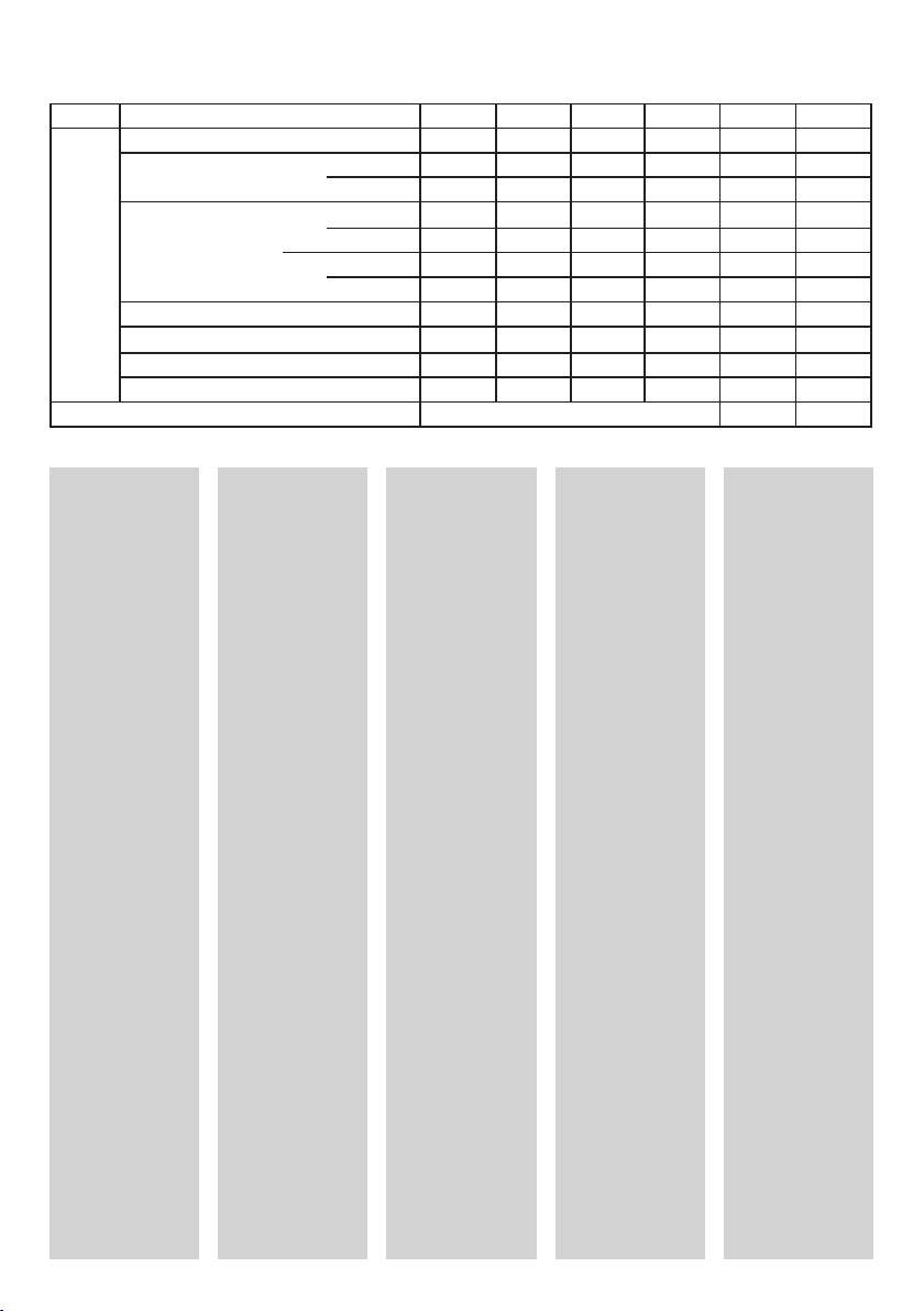
Typ Größe 0
Ident-Nr. 220206 220207 220208 220209 220210 220211
Vorrichtung
Einhängebereich bis 115 125 140 175 215 270
091
Verwendung vorwiegend für Futter bis Ø 250 315 400
1)
Schraubenwerkstoff 12.9
mm
Breite B 22 31 31 31 31 31
Schrauben-Ø D
Gewinde M 5 M 8 M 8 M 8 M 8 M 10
Gewicht ca. kg 1,5 3,3 5,2 5,6 6,8 8,3
1)
2)
leichte Ausführung
Außen-Ø 153 176 215 244 290 342
Innen-Ø 110 110 135 162 208 260
J Ø
A Ø
von 50 35 70 100 145 160
von 150 170 215 240 290 330
bis 215 260 285 315 360 440
2)
8,5 13 13 13 13 16
1234 5
c) Umkehren der
BAV-Backen
• Rändel nach links
drehen und Backen
entfernen.
• Backen umdrehen
(Schraubenköpfe
nach außen) und
wie folgt wieder
einsetzen:
• Backe 3 in Führung 1
• Backe 2 in Führung 2
• Backe 1 in Führung 3, hierbei
• Rändel wieder
nach rechts
drehen.
d) Eine schnelle
Drehbewegung des
Rändelrings kann
erreicht werden,
indem man einen
6 mm Rundstab oder
Durchschlag in die
hierfür vorgesehene Bohrung auf
der Planseite des
Rändelringes einführt
und diesen kurbelartig dreht.
Pfl ege
Periodisch etwas Öl
auf das Plangewinde
geben, hierzu Backen
ausbauen, stets
Schraubenköpfe
der Einstellbacken
bis zur Anlage in
die Senklöcher der
weichen Backen
einführen.
Einhängebereiche
dürfen nicht überfahren werden, da sonst
Beschädigungen
auftreten können.
Hinweise
a) Andrehen bzw.
Überdrehen von
ungehärteten
Blockbacken
Die Ausdreh-Vorrichtung BAV kann auch
bei der Drehbearbeitung von Blockbacken
eingesetzt werden,
hierzu empfi ehlt sich
in der vorderen Planfl äche der Backen je
1 Loch (vom Anwender) zu bohren. Die
Lage der Bohrungen
ist vom
gewünschten
Andrehbereich abhängig. (Es kann auf Anriss gebohrt werden).
b) Schleifen von
gehärteten Backen
Der Einsatz der Ausdreh-Vorrichtung BAV
beim Nachschleifen
von Backenstufen ist
sinngemäß möglich;
hierbei ist eine zu
starke Verschmutzung
der EinstellbackenVerzahnung zu vermeiden (Staub von Zeit
zu Zeit abpinseln).
c) Arbeitsbereich
Um den ganzen
Arbeitsbereich
(Spannbereich) des
Futters bzw. der
Backen überdecken
zu können, sind mindestens 2 BackenAusdrehvorrichtungen
erforderlich.
Garantie
Für innerhalb von
6 Monaten auftretende und berechtigte
Reklamationen über
nachgewiesene
Fehler in Werkstoff
und Ausführung
leisten wir kostenlosen Ersatz.
3
Page 4

GB
BAV Type 091 Jaw Cutting Attachment
Turning the outside diameter of
soft jaws
Turning the inside diameter of
soft jaws
Suspension range
Suspension range
Suspension
bolt
Normal
jaw position
Jaws
reversed
Housing
with scroll
Knurled
ring
Setting
jaw
Uses
The BAV cutting
attachment is mainly
used for turning the
inside and outside
diameters of soft
jaws on 3-jaw
chucks.
It permits the chuck
to be adjusted to the
condition in which
it will later grip the
work piece (pretightening) within a few
seconds.
This assures
positive gripping
and accurate
concentricity of the
machined clamping
surfaces of the
chuck jaws in the
tightened condition.
4
Applications
a) Turning soft top
jaws
b) Turning soft solid
jaws (See remarks)
c) Finish-grinding
hardened top jaws
(See remarks)
Design
features
A forged scroll with
a knurled ring is
manually rotated in
a robust housing to
move 3 setting jaws
provided with one
suspension bolt each
inward or outward.
The setting jaws
are reversible. The
knurled ring is turned
clockwise to reduce
the suspension
diameter, anti-clockwise to increase the
suspension diameter.
Use
a) Turning inside
diameters
• Use workpiece to
adjust the jaws
to be fi nished to
the required diameter (taking into
account the machining allowance).
• Position BAV
cutting attachment,
introducing the
bolt heads of the
setting jaws into
the counterbores
of the soft jaws.
• Turn knurled ring
anti-clockwise as
far as it will go.
• Using the manual
adjusting key,
fi rmly tighten the
chuck inwardly
against the bolt
heads of the setting jaws (without
workpiece).
• Turn jaws.
• Open chuck and
remove BAV
cutting attachment.
b) Turning outside
diameters
• Use workpiece to
adjust the jaws
to be fi nished to
the required diameter (taking into
account the machining allowance).
• Position BAV
cutting attachment,
introducing the
bolt heads of the
setting jaws into
the counterbores
of the soft jaws.
• Turn knurled ring
clockwise as far as
it will go.
• Using the manual
adjusting key,
fi rmly tighten the
chuck outwardly
against the bolt
heads of the setting jaws (without
workpiece).
• Turn jaws with
recessing tool.
• Open chuck and
remove BAV
cutting attachment.
Page 5

Type Size 0
Ident. No. 220206 220207 220208 220209 220210 220211
Attachments´s
Suspension distance to 115 125 140 175 215 270
mm
091
Width B 22 31 31 31 31 31
Scrwe head dia D
Thread M 5 M 8 M 8 M 8 M 8 M 10
Weight approx. kg 1,5 3,3 5,2 5,6 6,8 8,3
Used mainly with chucks up to dia. 250 315 400
1)
screw material 12.9
2)
2)
light-duty design
outer dia. 153 176 215 244 290 342
inner dia. 110 110 135 162 208 260
from 50 35 70 100 145 160
J Ø
from 150 170 215 240 290 330
A Ø
to 215 260 285 315 360 440
1)
8,5 13 13 13 13 16
1234 5
c) Reversing the
BAV jaws
• Turn knurled ring
anti-clockwise and
remove jaws.
• Reverse jaws (bolt
heads facing outward) and reinstall
as follows:
• Jaw 3 in slot 1,
• jaw 2 in slot 2,
• jaw 1 in slot 3
while
• turning the knurled
ring clockwise
again.
d) To speed up
the rotation of the
knurled ring, insert
a 6 mm round bar
or drift punch into
the hole provided for
that purpose in the
face of the knurled
ring and use it as a
crank.
Maintenance
Periodically apply a
small amount of oil
to the scroll thread,
removing the jaws.
Always insert the
bolt heads of the
setting jaws into the
counterbores of the
soft jaws as far as
they will go.
To avoid damage,
do not exceed the
suspension ranges.
Remarks
a) Turning the
steps or outside
diameters of soft
solid jaws
The BAV jaw cutting
attachment may also
be used for turning
solid jaws. In that
case, the user should
drill one hole each, in
the front face of the
jaws. The position of
these holes depends
on the desired step
turning range. (The
position of the hole
to be drilled can
be marked with a
scriber).
b) Grinding hardened jaws
Similarly, the BAV
cutting attachment
may be used for regrinding jaw steps. In
that case, excessive
dirt on the setting
jaw serrations must
be avoided. (Remove
dust with a brush
from time to time).
c) Working range
At least 2 cutting
attachments are
required to cover the
complete working
range (chucking
range) of the chuck
and jaws.
Warranty
Parts which give rise
to justifi ed claims on
account of verifi ed
material defects or
faulty workmanship
within a period of
6 months will be
replaced by us free
of charge.
5
Page 6

F
Dispositif BAV – Type 091 pour le tournage des mors au tour
Plage d‘accrochage
Position normale
des mors
Cage avec
bague
spirale
Tournage extérieure des mors
non trempés
Application
Domaines
d´application
Le dispositif BAV est
utilisé principalement
pour le tournage
intérieure et extérieure des mors doux
sur mandrins à trois
mors.
Ce dispositif permet
d´amener, en quelques secondes, le
mandrin à l´état dans
lequel il se trouvera
ultérieurement pour
l´usinage des pièces
(précontrainte).
En position de serrage, les faces actives des mors ainsi
usinées, adhèrent
mécaniquement et
sont parfaitement
concentriques.
a) Usinage, au
tour, de mors doux
rapportés
b) Usinage, au tour,
de mors monoblocs
non trempés (Veiller
aux indications)
c) Rectifi cation de
mors rapportés
trempés (Veiller aux
indications)
Usinage interne de mors doux
Description
Une bague spirale
forgée, logée dans
une cage robuste,
est commandée
à la main par une
couronne moletée.
Cette spirale déplace
vers l´intérieur ou
l´extérieur les 3 mors
réglables, portant
chacun une vis
d´accrochage.
Les mors réglables
sont réversibles.
La rotation de la
couronne moletée
vers la droite
réduit le diamètre
d´accrochage.
La rotation de la
couronne moletée
vers la gauche augmente le diamètre
d´accrochage.
Plage
d‘accrochage
Vis
d‘accrochage
Mode d‘emploi
a) Usinage intérieur
au tour
• A l´aide de la pièce,
ajuster au diamètre
les mors à aléser
au tour (veiller à la
surépaisseur pour
le tournage).
• Monter le dispositif
BAV; pour cela, introduire les têtes de
vis des mors réglables dans les alésages des mors doux.
•
Tourner la couronne
moletée vers la
gauche jusqu´à son
blocage.
• Avec la clé de
serrage, appliquer
énergiquement,
vers l´intérieur, le
mandrin contre les
têtes de vis des
mors réglables
(sans pièce).
• Usiner les mors.
• Ouvrir le mandrin,
déposer le dispositiv à tourner BAV.
Mors réglable
Position des
mors renversés
b) Usinage extérieur
au tour
• A l´aide de la pièce,
ajuster au diamètre
les mors à fi nir au
tour (veiller à la
surépaisseur de
tournage).
• Monter le dispositif
d´alésage BAV;
pour cela introduire
les têtes de vis
des mors réglables
dans les alésages
des mors doux.
•
Tourner la couronne
moletée vers la droite
jusqu´à son blocage.
• Avec la clé de
serrage, appliquer
énergiquement,
vers l´extérieur, le
mandrin contre les
têtes des vis des
mors réglables
(sans pièce).
• Finir les mors avec
l´outil à saigner.
• Ouvrir le mandrin,
déposer le dispositiv BAV à tourner.
Couronne
moltée
6
Page 7

type référence 0
n° id. 220206 220207 220208 220209 220210 220211
dispositiv
plage d´accrochage à 115 125 140 175 215 270
mm
091
largeur B 22 31 31 31 31 31
Ø de la tête de vis d
fi letage M 5 M 8 M 8 M 8 M 8 M 10
poids env. kgs 1,5 3,3 5,2 5,6 6,8 8,3
utilisation surtout sur mandrins jusqu´àu Ø: 250 315 400
1)
matière de la vis 12.9
1)
2)
exécution légère
Ø extérieur 153 176 215 244 290 342
Ø intérieur 110 110 135 162 208 260
J Ø
A Ø
de 50 35 70 100 145 160
de 150 170 215 240 290 330
à 215 260 285 315 360 440
1)
8,5 13 13 13 13 16
1234 5
c) Retournement des
mors du dispositif BAV
•
Tourner la couronne
moletée vers la
gauche et enlever
les mors.
•
Retourner les mors
(têtes de vis vers
l´extérieur) et remonter comme suit:
• Mors 3 dans guidage 1
• Mors 2 dans guidage 2
• Mors 1 dans guidage 3, puis
• tourner à nouveau
la couronne moletée
vers la droite.
d) On peut obtenir une
rotation rapide de la
couronne moletée en
introduisant une tige
cylindrique de 6 mm
ou un chasse-goupille,
dans l´alésage prévu
à cet effet sur la face
plane de la couronne,
que ainsi, pourra se
manoeuvrer à la façon
d´une manivelle.
Entretien
Rapporter périodoquement un peu
d´huile sur le fi letage
plan; à cet effet,
déposer les mors.
Les têtes de vis
des mors réglables
devront toujours être
introduites à fond
dans les alésages
des mors doux.
Ne pas dépasser les
plages d´accrochage,
car il pourrait en
résulter des avaries.
Indications
a) Façonnage ou
fi nition au tour des
mors monoblocs
non trempés
Le dispositif BAV
à tourner peut
également être
utilisé pour l´usinage,
au tour, des mors
monoblocs. Pour cela
il convient de percer
chaque fois un trou
dans la face avant
des mors (à réaliser
par l´utilisateur).
La position des
perçages dépend de
la plage d´usinage
souhaitée.
(On peut percer sur
traçage).
b) Rectifi cation de
mors trempés
Le dispositif est
utilisable, par
analogie, pour la
reprise par rectifi cation des mors
étagés; il convient
toutefois d´éviter
l´encrassement important de la denture
des mors réglables.
(Enlever de temps en
temps la poussière
au pinceau).
c) Rayon d´action
Pour couvrir
l´ensemble du rayon
d´action (plage de
serrage) du mandrin
ou des mors, il faut
au moins deux dispositifs de tournage
des mors.
Garantie
Nous remplaçons
gratuitement
l´apparail à la
suite de réclamations
justifi ées concernant
des défauts prouvés
de matière et
de frabrication
intervenant dans les
6 moins.
7
Page 8

E
Dispositivo para mecanizar y rectifi car de garras BAV tipo 091
Margen
de suspensión
Posición normal
de las garras
Caja con
anillo
espiral
Torneado exterior de garras no
templadas
Finalidad de
aplicación
El dispositivo para
el torneado BAV
encuentra especialmente aplicación
para el torneado
interior y torneado
exterior de garras no
templadas e platos
de tres garras.
Con su ayuda, en
pocos segundos
puede establecerse
el estado del plato
que posteriomente
adquirirá para el mecanizado de la pieza
(sujeción previa).
De este modo,
las superfi cies de
sujeción torneadas
de las garras del
plato facilitan una
sujeción de unión
positiva y exactamente concéntrica.
8
Campos de
aplicación
a) Torneado de
garras postizas no
templadas
b) Torneado de garras monobloque no
templadas (Véanse
las instrucciones al
respecto)
c) Rectifi cado de
garras postizas
templadas (Véanse
las instrucciones al
respecto)
Torneado interior de garras no
templadas
Características
de construcción
En una caja robusta
se gira manualmente
un anillo espiral
forjado sobre una
moleta. Esta espira
mueve 3 garras de
ajuste, en las que se
encuentra aplicado
en cada caso un tornillo de suspensión,
hacia dentro o hacia
fuera.
Las garras de ajuste
son reversibles.
Girando el anillo
moleteado hacia la
derecha, se reduce
el diámetro de
suspensión,
girando el anillo
moleteado hacia la
izquierda, se aumenta
el diámetro de
suspensión.
Margen
de suspensión
Tornillo de
suspensión
Aplicación
a) Torneado interior
•
Ajustar el diámetro
de las garras a tornear con ayuda de la
pieza (observar la
demasia de torneado).
•
Montar el dispositivo
para el torneado BAV;
al mismo tiempo, incorporar las cabezas
de los tornillos de
las garras de ajuste
en los agujeros
avellanados de las
garras no templadas.
•
Girar la moleta
hacia la izquierda
hasta que quede
bien asentada.
•
Con ayuda de la llave
de sujeción manual,
apretar fuertemente
hacia dentro el plato
contra las cabezas
de los tornillos de las
garras de ajuste (sin
pieza).
•
Efectuar el torneado
de las garras.
• Abrir el plato, retirar
el dispositivo para el
torneado BAV.
Moleta
Garra de
ajuste
Posición invertida
de las garras
b) Torneado exterior
•
Ajustar el diámetro de
las garras a torne-ar
con ayuda de la pieza
(observar la demasia
de torneado).
• Montar el dispositivo
para el torneado BAV;
al mismo tiempo, incorporar las cabezas
de los tornillos de las
garras de ajuste en
los agujeros avellanados de las garras no
templadas.
• Girar la moleta hacia
la derecha hasta que
quede bien asentada.
• Con ayuda de la llave
de sujeción manual,
apretar fuertemente el
plato hacia el exte
contra las cabezas
los tornillos de las garras de ajuste (sin pieza).
•
Efectuar el torneado
ex
terior de las garras
con una cuchilla de
ranurar.
• Abrir el plato, retirar
el dispositivo para el
torneado BAV.
rior
de
Page 9

Tipo Referencia 0
No. Ident. 220206 220207 220208 220209 220210 220211
Dispositivo
Margen de suspension a 115 125 140 175 215 270
mm
091
Ancho B 22 31 31 31 31 31
Ø cabeza del tornillo D
Rosca M 5 M 8 M 8 M 8 M 8 M 10
Peso aprox. kg 1,5 3,3 5,2 5,6 6,8 8,3
Adrecuado para platos con Ø de 250 315 400
1)
Material del tornillo 12.9
2)
2)
ejecución ligera
Ø exterior 153 176 215 244 290 342
Ø interior 110 110 135 162 208 260
J Ø
A Ø
de 50 35 70 100 145 160
de 150 170 215 240 290 330
a 215 260 285 315 360 440
1)
8,5 13 13 13 13 16
1234 5
c) Inversión de las
garras BAV
• Girar la moleta
hacia la izquierda y
retirar las garras.
• Dar la vuelta a las
garras (.as cabezas
de los tornillos
hacia fuera) y montarlas como sigue:
• Garra 3 en la guia 1
• Garra 2 en la guia 2
•
Garra 1 en la guia 3
al mismo tiempo
• girar la moleta
de nuevo hacia la
derecha.
d) Un movimiento
ràpido de giro del
anillo moleteado
puede obtenerse,
metiendo una barra
cilíndrica de 6 mm o
un punzón en el orifi cio para esto previsto
en la cara frontal del
anillo moleteado,
girando ahora como
si fuera una manivela.
Cuidado y
conservación
Aplicar periódicamente algo de aceite
sobre la rosca plana,
para esto, desmontar
las garras; las
cabezas de los tornillos de las garras
de ajuste deberán
introducirse siempre
hasta el tope en los
agujeros avellanados
de las garras no
templadas.
,
Los márgenes de
suspensión no deben
ser excedidos, ya
que de otra manera
se causarian daños.
Notas
a) Torneado interior
o torneado exterior,
respectivamete, de
garras monobloque
no templadas
El dispositivo para
el torneado BAV
también puede ser
utilizado para el
torneado de garras
monobloque, para
esto recomendamos
taladrar en cada
caso 1 agujero en
la superfi cie plana
frontal de las garras
(por el usuario).
La posición de los
agujeros depende
del margen de torneado inicial deseado.
(Puede realizarse
un taladrado de
trazado).
b) Rectifi cado de
garras templadas
El dispositivo para el
torneado BAV tamién
puede ser utilizado
análogamente para
el rectifi cado posterior de escalones en
las garras; en este
caso deberá evitarse
el ensuciamiento
extremo del dentado
de las garras de
ajuste (limpiar
regulamente el polvo
con un pincel).
c) Campo de
trabajo
Para poder cubrir
todo el campo de
trabajo (alcance o
margen de sujeción)
del plato o de las
garras, respectivamente, se necesitan
como minimo 2
dispositivos para el
torneado interior de
garras.
Garantía
En el caso de
que se presenten
reclamaciones
fundadas dentro de 6
meses después de la
entrega sobre fallas
de material y de ejecución, se realizará
un suministro de
repuesto gratuito.
9
Page 10

I
Dispositivo di tornitura griffe BAV – Tipo 091
Campo di fi ssaggio
Posizione normale
delle griffe
Gabbia
con anello
a spirale
Tornitura esterna al tornio di
griffe non temprate
Impiego
Campi
d´applicazione
Il dispositivo BAV è
utilizzato prevalentemente per la tornitura interna e per
la tornitura esterna
al tornio delle griffe
dolci di autocentrante
a tre griffe.
Il dispositivo consente di predisporre
l´autocentrante,
entro pochi secondi,
nelle condizioni di
precarico richieste al
fi ni della successiva
lavorazione del
pezzo.
In posizione di serraggio le facce attive
delle ganasce tornite
in tal modo aderiscono ad accoppiamento
geometrico e con
perfetta concentricità.
10
a) Tornitura di
griffe riportate non
temprate
b) Tornitura di griffe
monoblocco non
temprate (Osservare
le note riportate a
tergo)
c) Rettifi ca di griffe
riportate temprate
(Osservare le note
riportate a tergo)
Tornitura interna di griffe non
temprate
Caratteristiche
costruttive
Un anello a spirale
forgiato, supportato
da una gabbia
robusta, è azionato
a mano, per mezzo
di una rotella zigrinata. La spirale
provvede a spostare
verso l´interno o
l´esterno le tre griffe
d´aggiustaggio di cui
ognuna è dotata di
una vite di aggancio.
Le griffe
d´aggiustaggio sono
invertibili.
La rotazione in senso
orario della rotella
zigrinata comporta
la riduzione del ø
d´aggancio.
La rotazione in
senso antiorario
della rotella zigrinata
comporta l´aumento
del ø d´aggancio.
Campo
di fi ssago
Vite
d‘aggancio
Modalità d´uso
a) Tornitura interna
•
Aggiustare le griffe
da tornire, con il
pezzo, al diametro
voluto (tenendo conto del sovrametallo).
•
Applicare il
dispositivo BAV,
inserendo le teste
delle viti delle griffe
d´aggiustaggio negli
appositi fori ricavati
nelle griffe dolci.
•
Ruotare la rotella zigrinata verso sinistra,
fi no al bloccaggio.
• Forzare
energicamente
verso l´interno
l´autocentrante,
con la chiave di
serraggio, contro
le teste delle viti
delle ganasce
d´aggiustaggio
(senza pezzo).
•
Eseguire la tornitura
interna delle griffe.
•
Disimpegnare
l´autocentrante
e rimuovere il
dispositivo BAV.
Rotella
zigrinata
Griffe
d‘aggiustaggio
Posizione griffe
invertite
b) Tornitura esterna
al tornio
•
Aggiustare le griffe
da tornire, con il
pezzo, al diametro
voluto (tenendo conto della sovraquota
di lavorazione).
• Applicare il dispositivo BAV, inserendo le
teste delle viti delle
griffe d´aggiustaggio
negli appositi fori fi cavate nelle griffe dolci.
• Ruotare la rotella zigrinata verso destra,
fi no al bloccaggio.
•
Forzare energicamente verso l´esterno
l´autocentrante,
con la chiave di
serraggio, contro le
teste delle viti delle
griffe d´aggiustaggio
(senza pezzo).
• Eseguire la tornitura
esterna delle griffe,
con l´utensile per
spogliare.
• Disimpegnare l´autocentrante e rimuovere il dispositivo BAV.
Page 11

art. grand. 0
codice 220206 220207 220208 220209 220210 220211
attrezzo
campo di fi ssaggio a 115 125 140 175 215 270
mm
091
larghezza B 22 31 31 31 31 31
Ø testa vite D
fi letto M 5 M 8 M 8 M 8 M 8 M 10
peso ca. kg 1,5 3,3 5,2 5,6 6,8 8,3
adatto per mandrini fi no a diametro: 250 315 400
1)
materiale 12.9
2)
2)
esecuzione leggera
Ø est. 153 176 215 244 290 342
Ø int. 110 110 135 162 208 260
J Ø
A Ø
da 50 35 70 100 145 160
da 150 170 215 240 290 330
a 215 260 285 315 360 440
1)
8,5 13 13 13 13 16
1234 5
c) Inversione delle
griffe BAV
•
Ruotare a sinistra
la rotella zigrinata
e togliere le griffe.
•
Invertire le griffe
(teste delle viti
rivolte all´esterno)
e reinserirle come
segue:
•
griffe 3 nella
guida 1
•
griffe 2 nella
guida 2
•
griffe 1 nella
guida 3; nel
contempo
•
ruotare a destra la
rotella zigrinata.
d) Per accelerare
il moto rotativo
della rotella zigrinata,
inserire un´astina
tonda 6 mm oppure
un punzone nel foro
appositamente previsto sula porzione
piana della rotella e
ruotare la medesima
a modo di manovella.
Manutenzione
Ingrassare periodicamente, con un poco
di olio, la fi lettatura
piana, dopo aver
smontato preventivamente le griffe.
Non eccedere le
quote d´aggangio
per evitare eventuali
danneggiamenti.
Note da
osservare
a) Sagomatura o
tornitura di griffe
monoblocco non
temprate
Il dispositivo BAV può
servire anche per la
tornitura delle griffe
monoblocco. Sie raccomanda a questo
scopo di praticare
(sul posto) un foro
nellla faccia piana
frontale delle ganasce. La posizione del
foro dipenderà dalla
quota di sagomatura
richiesta. (Si può
praticare il foro
previa tracciatura).
b) Rettifi ca di griffe
temprate
L´uso del dispositivo
BAV per la rettifi ca
die piani delle griffe è
possibile in analogia
a quanto suddetto; si
bada comunque ad
evitare l´eccessivo
insudiciamento
della dentatura delle
griffe d´aggiustaggio
(asportare ogni tanto
la polvere con un
pennello).
c) Campo utile
dell´autocentrante
Per ricoprire
l´intero raggio utile
dell´autocentrante
(campo di serraggio)
ossia delle griffe,
occorrono almeno
2 dispositivi di
tornitura.
Garanzia
Il costruttore sostituisce gratuitamente
il materiale fornito
in caso di anomalie
inerenti il materiale
e la esecuzione del
dispositivo, a fronte
di contestazioni
giustifi cate che dovrebbero sopravvenire
entro i primi 6 mesi
dalla messa in opera.
11
Page 12

RÖHM GmbH • Postfach 11 61 • 89565 Sontheim/Brenz • Germany
Tel. 0 73 25 / 16-0 • Fax 0 73 25 / 16-4 92
www.roehm-spannzeuge.com
E-Mail: info@roehm-spannzeuge.com
Id.-Nr.: 242045 / 0906 H
 Loading...