

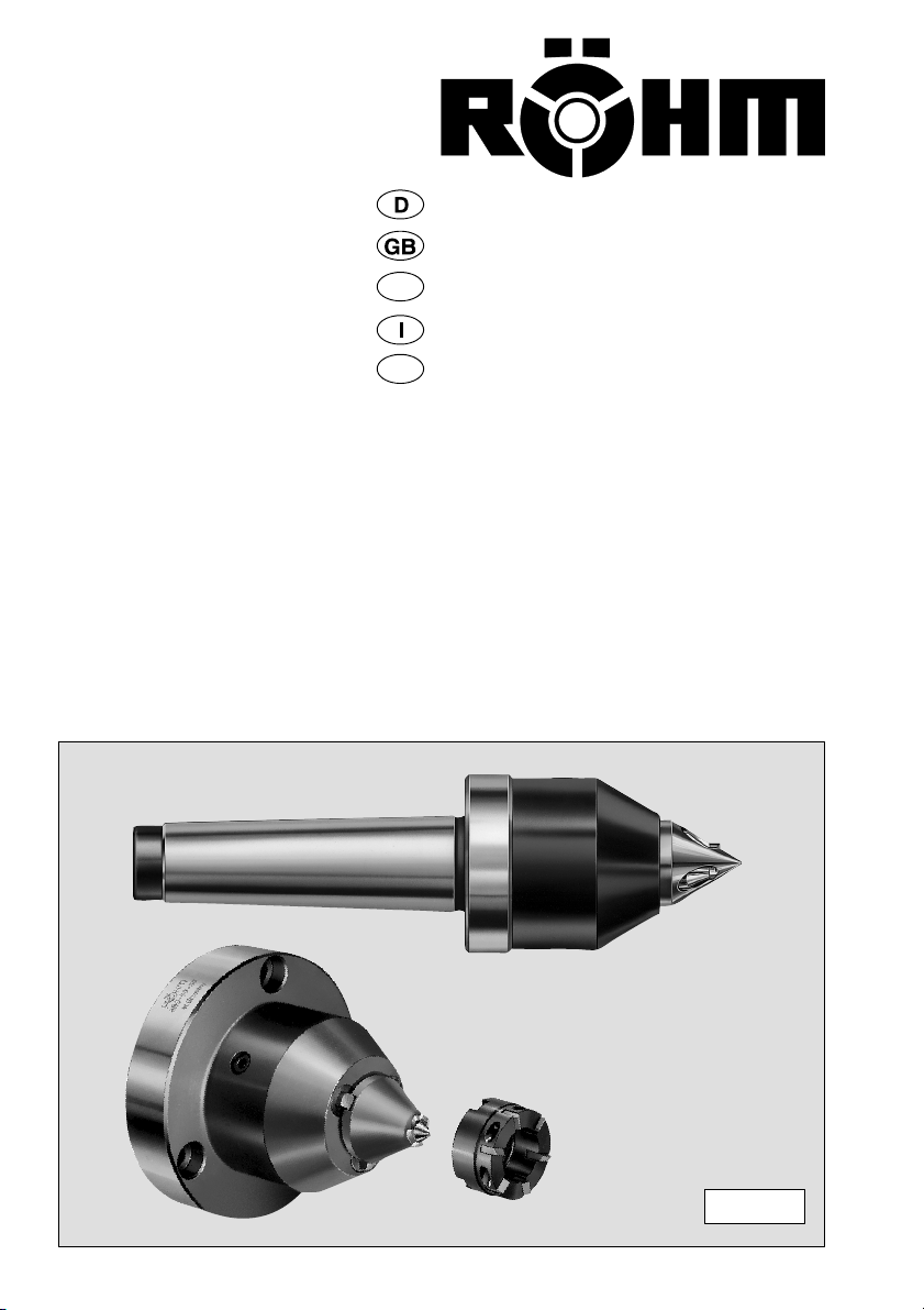
Page 1
Bedienungsanleitung für
Operating Instructions for
Instructions de service pour
Istruzioni per l’uso
Instrucciones de servicio para
Constant Stirnseiten-Mitnehmer
Constant Face Drivers
Entraîneur frontal Constant
Trascinatori frontali Constant
Puntos de arrestre frontal Constant
E
F
Stand: 06/03
CoG
CoK
Kraftbetätigte Ausführung
Power-actuated design
Commande hydraulique
Comando automatico
Mando automático
Page 2

Inhalt -- Contents -- Table de matières -- Indice
Die Stirnseiten-Mitnehmer mit ihren wichtigsten
Einzelteilen 3-5.....................................
1. Sicherheitshinweise und Richtlinien für den Einsatz
von Stirnseiten-Mitnehmern 6.........................
2. Inbetriebnahme der Stirnseiten-Mitnehmer CoG 7.......
3. Maßübersicht 8.....................................
4. Ersatzteile 8-9......................................
5. Wechseln der Mitnehmer-Bolzen oder der
Zentrierspitze 9-10..................................
6. Inbetriebnahme der Stirnseiten-Mitnehmer
CoK Typ 690-00 10-11..............................
7. Maßübersicht 12...................................
8. Ersatzteile 12-13....................................
9. Inbetriebnahme der Stirnseiten-Mitnehmer
CoK Typ 689-00 14-16..............................
10. Maßübersicht 17...................................
11. Ersatzteile 17......................................
The Face drivers with its most important components 3-5.
1. Safety requirements and rules and regulations for the
use of Face-Drivers 6................................
2. Preparations for use Face driver CoG 7................
3. Dimensions 8.......................................
4. Spare parts 8-9.....................................
5. Changing the driving pin or the centering point 9-10......
6. Preparations for use Face driver
CoK Type 690-00 10-11.............................
7. Dimensions 12.....................................
8. Spare parts 12-13...................................
9. Preparations for use Face driver
CoK Type 689-00 14-16.............................
10. Dimensions 17.....................................
11. Spare parts 17.....................................
Entraîneur frontal avec ses pièces détachées les plus
importantes 3-5.....................................
1. Indications concernant la sécurité et directives pour
l’utilisation d’entraîneur frontal 6.......................
2. Mise en service entraîneur frontal CoG 7...............
3. Dimensions 8.......................................
4. Pièces de rechange 8-9.............................
5. Remplacement des goupilles d’entraînement ou 9-10....
de la pointe de centrage
6. Mise en service entraîneur frontal
CoK type 690-00 10-11..............................
7. Dimensions 12.....................................
8. Pièces de rechange 12-13...........................
9. Mise en service entraîneur frontal
CoK type 689-00 14-16..............................
10. Dimensions 17.....................................
11. Pièces de rechange 17.............................
Trascinatori frontali con i suoi particolari principali 3-5...
1. Norme de sicurezza e direttive per l’impiego di
trascinatori frontali 6................................
2. Messa in funzione trascinatori frontali CoG 7...........
3. Dimensioni 8......................................
4. Pezzi di ricambio 8-9...............................
5. Sostituzione dei denti di trascinamento oppure 9-10....
della punta di centramento
6. Messa in funzione trascinatori frontali
CoK art. 690-00 10-11..............................
7. Dimensioni 12.....................................
8. Pezzi di ricambio 12-13.............................
9. Messa in funzione trascinatori frontali
CoK art. 689-00 14-16..............................
10. Dimensioni 17.....................................
11. Pezzi di ricambio 17................................
El puntos de arrastre frontal con sus
componentes más importantes 3-5...................
1. Instrucciones de seguridad y directrices para el uso
de arrestre frontal 6................................
2. Puesta en servicio puntos de arrastre frontal CoG 7....
3. Dimensiones 8.....................................
4. Piezas de repuesto 8-9.............................
5. Cambio del perno arrastrador o de la contrapunta 9-10..
6. Puesta en servicio puntos de arrastre frontal
CoK tipo 690-00 10-11.............................
7. Dimensiones 12....................................
8. Piezas de repuesto 12-13...........................
9. Puesta en servicio puntos de arrastre frontal
CoK tipo 689-00 14-16.............................
10. Dimensiones 17....................................
11. Piezas de repuesto 17..............................
2
Page 3
Id.-Nr. .........
Id.-Nr. ...............
6143
5789102
SW 10
E
F
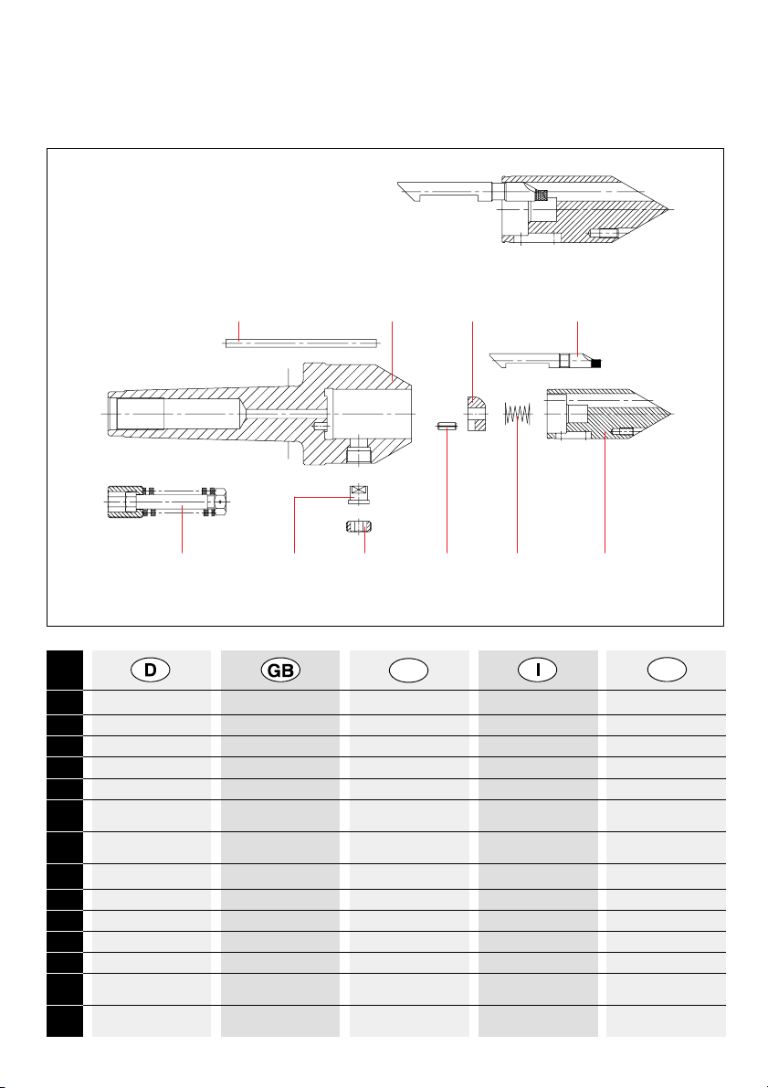
Tei l Benennung Name Désignation Denominazione Denominación
1 Körper Body Corps de base Corpo Cuerpo base
2 Zentrierspitze Centering point Pointe de centr age Punta di centramento Contrapunta
3 Mitnehmer-Bolzen Driving pin Goupilles d’entraînement Dente di trascinamento Perno arrastrador
4 Ausgleichsring Compensating ring Bague de compensation Anello di compensazione Anillo de compensación
5 Federpaket MK 4-5 Compression spring Ressort de compression Molla di compressione Resorte de compresión
MK 4-5 MK 4-5 MK 4-5 MK 4-5
5 Federpaket MK 3 Compression spring Ressort de compression Molla di compressione Resorte de compresión
MK3MK3MK3MK3
6 Zylinderstift MK 4-5 Parallel pin MK 4-5 Axe cylindrique MK 4-5 Spina cilindrica MK 4-5 Pasador cilindr. MK 4-5
6 Zylinderstift MK 3 Parallel pin MK 3 Axe cylindrique MK 3 Spina cilindrica MK 3 Pasador cilindr. MK 3
7 Haltebolzen Retaining bolt Boulon de retenue Perno di arresto Perno de sujeción
8 Gewindering Ring nut Bague filetée Ghiera filettata Anillo roscado
9 Spannhülse Clamping sleeve Douille de serrage Perno di arresto Manguito de sujeción
10 Druckfeder Spannkreis- Compression spring -- Ressort de press., Ø du Molla dia. 12-23 Resorte de com pr. diá.
Ø 12-23 clamping dia. 12 t o 23 cercle de serrage 12-23 de círc. suj. de 12 a 23
10 Druckfeder Spannkreis- Compression spring -- Ressort de press., Ø du Molla dia. 8-10 Resorte de compr. diá.
Ø8-10 clampingdia.8to10 cercledeserrage8-10 decírc.suj.de8a10
Der Stirnseiten-Mitnehmer CoG mit seinen wichtigsten Einzelteilen
CoG Face drivers and their most important components
Entraîneur frontal Constant CoG avec ses principales pièces constitutives
Trascinatori frontali Constant CoG con i suoi particolari principali
Puntos de arrastre frontal Constant CoG con sus componentes más importantes
313037 313036 013571
Ø 12-23: 313090
Ø 8-10: 689155
313009
MK 4- 5: 313038/007860
MK 3: 313039
MK 4- 5: 313251
MK 3: 313026
siehe Hauptkatalog
see general catal.
313019
siehe Seite 5
see page 5
3
Page 4
Id.-Nr. ...........................
Id.-Nr. ..................................
E
F
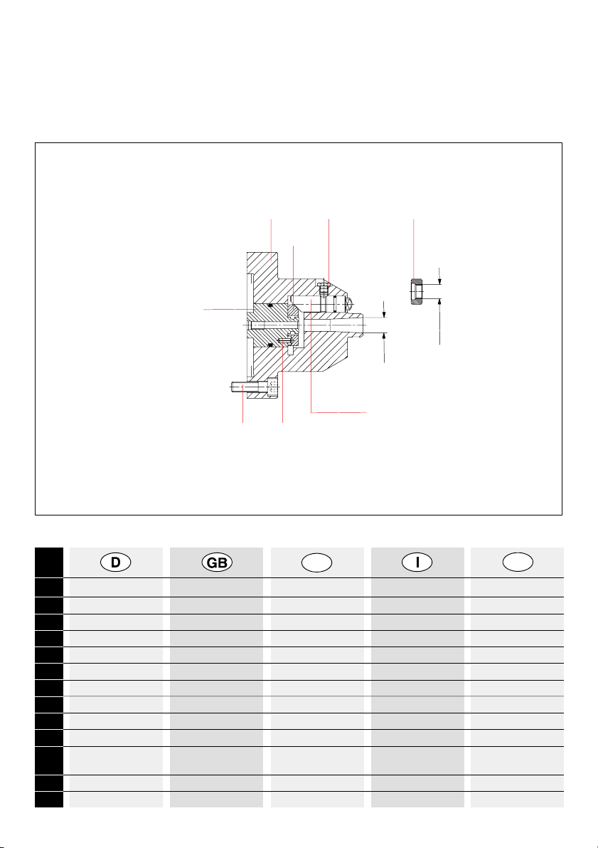
Tei l Benennung Name Désignation Denominazione Denominación
1 Körper Body Corps de base Corpo Cuerpo base
2 Abstützkolben komplett Supporting bolt assy Boulon d’appui, compl. Punto di centram., compl. Bulón de apoyo, compl.
2 Abstützkolben Supporting bolt Boulon d’appui Punto di centramento Bulón de apoyo
2 O-Ring O-Ring O-Ring O-Ring O-Ring
3 Ausgleichsring Compensating ring Bague de compensation Dente di trascinamento Anillo de com pensación
4 Druckkolben komplett Pressure piston assy Piston de pression, compl. Pistone di compr., compl. Pistón de presión, compl.
4 Druckkolben Pressure piston Piston de pression Pistone di compressione Pistón de presión
4 O-Ring O-Ring O-Ring O-Ring O-Ring
5 Abdrückmutter Draw-off nut Écrou à chasser Ghiera di estrazione Tuerca de extracción
6 Zylinderschraube Filist er head screw Vis à tete cylindrique Vite a test a cilindrica Tornillo cilindrico
M 10 x 35 DIN 912 M 10 x 35 DI N 912 M 10 x 35 DIN 912 M 10 x 35 DIN 912 M 10 x 35 DIN 912
7 Schmiernippel Lubricating nipple Graisseur Nipplo di lubrificazione Lubricador
8 Spannhülse Clamping sleeve Douille de serrage Perno di arresto Manguito de sujeción
Der Stirnseiten-Mitnehmer CoK Typ 690-00 mit seinen
wichtigsten Einzelteilen
CoK Face drivers Typ 690-00 and their most important components
Entraîneur frontal Constant CoK Typ 690-00avec ses principales pièces constitutives
Trascinatori frontali Constant CoK Typ 690-00 con i suoi particolari principali
Puntos de arrastre frontal Constant CoK Typ 690-00 con sus componentes más importantes
6
4
1
8
3
2
75
M14x1,5
Ø15
Druckkolben kpl.: Id.-Nr. 313651
Pressure piston assy
Piston de pres sion, compl.
Pistone di compr., compl.
Pistón de pres ión, compl.
Druckkolben: 313652
Pressure piston
Piston de pres sion
Pistone di compr.
Pistón de pres ión
O-Ring: 006260
313901
313650
027380 089229
249301 321975
Abstützkolben kpl.: Id.-Nr.: 313648
Supporting bolt ass y
Boulon d’appui, compl.
Punto di centramento, compl.
Bulón de apoyo, compl.
Abstützkolben: 313649
Supporting bolt
Boulon d’appui
Punto di centramento
Bulón de apoyo
O-Ring: 006222
4
Page 5
E
F
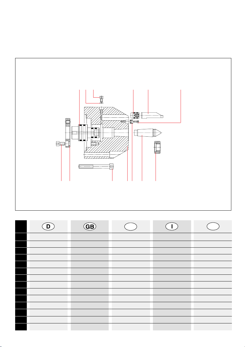
Tei l Benennung Name Désignation Denominazione Denominación
1 Körper Body Corps de base Corpo Cuerpo base
2 Zentrierspitze Centering point Pointe de centrage Punta di centramento Contrapunta
3 Mitnehmer-Bolzen Driving pin Goupilles d’entraînement Dente di trascinamento Perno arrastrador
4 Paßstück Adapter piece Cale d’ajustage Arresto dente trascin. Pieza de ajust e
5 Kolben bolt Boulon Pistone Bulón
6 Druckkolben Pressure piston Piston de pression Pistone di compressione Pistón de presión
7 Anschlag stop butée Arresto tope
8 Entlüftungsschraube venting screw vis de purge d’air Vite di spurgo tornillo de escape de aire
9 Abdrückmutter Draw-off nut Écrou à chasser Ghiera di estrazione Tuerca de extracción
10 Zylinderschraube M 10 Filister head screw M 10 Vis à tete cyl. M 10 Vite a testa cil. M 10 Tornillo cilindrico M 10
11 Zylinderschraube M 8 Filister head screw M 8 Vis à tete cyl. M 8 Vite a testa cil. M 8 Tornillo cilindrico M 8
12 Zylinderschraube M 4 Filister head screw M 4 Vis à tete cyl. M 4 Vite a testa cil. M 4 Tornillo cilindrico M 4
13 Usit-Ring Usit ring Bague Usit Guarnizione Anillo Usit
Der Stirnseiten-Mitnehmer CoK Typ 689-00 mit seinen
wichtigsten Einzelteilen
CoK Face drivers Typ 689-00 and their most important components
Entraîneur frontal Constant CoK Typ 689-00avec ses principales pièces constitutives
Trascinatori frontali Constant CoK Typ 689-00 con i suoi particolari principali
Puntos de arrastre frontal Constant CoK Typ 689-00 con sus componentes más importantes
813
11 7
6
10
14 2 9
53 12
5
Page 6
Während des Hantierens mit Stirnseiten-Mitnehmern vorsichtig vorgehen. Herunterfallende
Stirnseiten-Mitnehmer
können aufgrund ihrer
Masse und der Form
der Spitze schwere Verletzungen hervorrufen.
Sicherheitsschuhe
tragen!
Die Pinolenachse muss
fluchtend zur Spindelachse ausgerichtet sein.
Ansonsten kann die gehärtete Laufspitze aufgrund der auftretenden
Querkräfte brechen und
das rotierende Werkstück herausgeschleudert werden.
Werkstücke mit ungenauen bzw. schräg zur
Achse angeordneten
Zentrierbohrungen führen ebenfalls bei umlaufendem Betrieb zu einer
Wechselbiegung des
Stirnseiten-Mitnehmers.
Diese können ebenfalls
zum Bruch der gehärteten Laufspitze mit den
zuvor genannten Folgen
führen.
1. Sicherheitshinweise und Richtlinien für den Einsatz
von Stirnseiten-Mitnehmern
Safety requirements and rules and regulations for the use of Face-Drivers
Indications concernant la sécurité et directives pour l’utilisation d’entraîneur frontal
Norme de sicurezza e direttive per l’impiego di trascinatori frontali
Instrucciones de seguridad y directrices para el uso de arrestre frontal
Please proceed carefully when handling
Face Drivers. On account of the mass and
the shape of the centre
dropping Face Drivers
may cause severe injuries. Wear safety shoes!
The tailstock sleeve has
to be in true alignment
with the spindle axle.
Otherwise the hardened
centre may break due to
the transverse forces
occurring, and the rotating work piece is hurdled out.
Work pieces with imprecise or off--centre centre
holes will also cause an
alternate bending of the
centre in case of rotating operation. This action may also lead to the
rupture of the hardened
Face Driver causing the
consequences mentioned above.
Pendant la manipulation
des entraîneur frontal,
opérer avec prudence.
Si des entraîneur frontal
tombent sur le sol, elles
peuvent causer de graves blessures en raison
de leur masse et de la
forme de la pointe. Por-
ter des chaussures de
sécurité!
L’axe du fourreau de la
broche doit être orienté
en alignement à l’axe de
la broche. Sinon la
pointe de roulement durcie peut se casser en
raison des forces de cisaillement et la pièce à
usiner en rotation être
projetée.
Les pièces à usiner
avec des trous de centrage mal disposés ou
disposés en biais par
rapport à l’axe provoquent également une
flexion alternée de la
pointe en exploitation
rotative. Ces pièces
peuvent également causer la cassure des
pointes de roulement
durcies avec les
conséquences citées au
préalable.
In caso di caduta della
contropunta il peso e la
forma della contropunta
stessa possono causare
ferite gravi. Indossare
sempre scarpe antinfortunistiche.
L’asse della contropunta
deve essere allineato
con l’asse mandrino.
In caso contrario, lo
sforzo di taglio che si
viene a creare può causare la rottura della cuspide ed il pezzo da lavorare può essere proiettato lontano dall’area di
lavoro
I pezzi da lavorare con
fori di centraggio imprecisi, oppure inclinati rispetto all’asse possono
essere causa della maggiore sollecitazione a fatica della contropunta.
Questo può causare la
rottura della cuspide
temprata, con le conseguenze sopra citate.
El personal manipulador
deberá haber estudiado
a fondo las presentes
instrucciones de uso, y
particularmente el
capítulo dedicado a las
Instrucciones de seguridad.
El montaje, manejo y
mantenimiento deberá
ejecutarse correctamente.
El operador deberá abstenerse de todo proceder que pueda afectuar
su seguridad.
Como complemento a
las instrucciones de uso
deberán observarse los
reglamentos generales
y legales de caracter
obligatorio para la prevención de accidentes y
para la protección contra accidentes.
Deberán abservarse
con exactitud las indicaciones y recomendaciones dadas en las instrucciones de uso
E
F
6
Page 7

2. Inbetriebnahme
2.1 Stirnseiten-Mitnehmer CoG
Bestens geeignet
zum rationellen Spannen und Überdrehen
von kleineren Werkstücken, bei denen
eine besonders hohe
Rundlaufgenauigkeit
gefordert wird.
Nach dem Baukastenprinzip entwikkelt, deshalb universeller Austausch von
Mitnehmerbolzen und
Zentrierspitzen untereinander möglich.
Beim schnellen Umrüsten auf einen anderen Spannkreis-Ø,
oder andere Laufrichtung, wird zweckmäßigerweise die
komplette Einheit, bestehend aus Zentrierspitze, Mitnehmerbolzen und Druckfeder
gewechselt.
Die groß dimensionierte Zentrierspitze
garantiert auch im
rauhen Dauereinsatz
höchste Genauigkeit.
Durch den mechanischen Ausgleich der
3 lang geführten Mitnehmerbolzen und
die federnde Zentrierspitze ergibt sich ein
starrer WerkstückLängsanschlag an
der Planfläche.
Ausgleich der Mitnehmerbolzen untereinander über 2 mm.
Werkstückgewicht bis
max. 100 kg möglich.
Sonderausführungen
auf Anfrage.
Puesta en servicio
Puntos de arrastre
frontal Constand
CoG
Apropiado del mejor
modo posible para la
sujeción y el repasado en torno de piezas a trabajar más
pequeñas, en las que
se requiere una precisión de concentricidad especialmente
elevada.
Habiendo sido diseñado en forma de
sistema de unidades
montables normalizadas, es posible el recambio universal de
pernos arrastradores
y de contrapuntas.
En el reequipamiento
rápido para otro
diám. de círculo de
sujeciónuotradirección de marcha, convenientemente se
cambia la unidad
completa compuesta
por contrapunta,
perno arrastrador y
resorte de compresión.
La contrapunta de
grandes dimensiones
garantiza máxima
precisión, aún con
aplicación permanente bajo condiciones duras.
Debido a la compensación mecánica de
los 3 pernos arrastradores, con guía larga,
y la contrapunta bajo
presión de muelle, se
obtiene un tope longitudinal fijo para la
pieza a trabajar en la
superficie plana.
Compensación de los
pernos arrastradores
entre sí: más de 2
mm.
La pieza a trabajar
puede pesar máx.
100 kg. Ejecuciones
especiales sobre demanda.
Messa in funzione
Trascinatori frontali
Constant CoG
Particolarmente adatti
per il trascinamento
di piccoli pezzi, per i
quali è richiesta una
elevata precisione di
concentricità, in operazioni di tornitura
esterna.
Sviluppati secondo il
principio di costruzione modulare, permettono una assoluta
intercambiabilità delle
testine di trascinamento e delle punte
di centramento.
In caso di riattrezzamento veloce su un
diverso diametro di
trascinamento, oppureinunaltrosenso
di rotazione, viene
fornita l’unità completa, composta di
punta di centramento,
denti di trascinamento e molla di
compressione.
La grande dimensione della punta di
centramento garantisce la massima precisione anche in caso
di impiego pesante e
continuo.
Grazie alla compensazione meccanica
dei 3 denti di trascinamento con guida
longitudinale ed alla
punta di centramento
precaricata, è possibile ottenere un arresto pezzo longitudinale affidabile e preciso.
Compensazione reciproca dei denti di trascinamento maggiore
di 2 mm.
Peso massimo del
pezzo 100 Kg.
Esecuzioni speciali
su richiesta.
Mise en service
Entraîneur frontal
Constant CoG
Parfaitement indiqué
pour serrer et tourner
rationnellement des
pièces à usiner relativement petites pour
lesquelles une précision de concentricité
particulièrement
élevée est exigée.
Conçu selon le principe modulaire et permettant donc
l’échange universel
des goupilles d’entraînement et des
pointes de centrage
entre elles.
Pour le changement
d’équipement rapide
pour un autre Ø du
cercle de serrage ou
pour un autre sens de
la marche, vous remplacez, de manière
appropriée, l’unité
complète composée
de la pointe de centrage, des goupilles
d’entraînement et du
ressort de pression.
La pointe de centrage
de grande dimension
garantit la précision la
plus élevée même en
service rude continu.
La compensation
mécanique des 3
goupilles d’entraînement à guidage longitudinal et la pointe de
centrage sur ressort
assurent une butée
longitudinale fixe de
la pièce à usiner sur
la surface plane.
Compensation des
goupilles d’entraînement entre elles sur 2
mm.
Poids max. admissible pour la pièce à
usiner 100 kg.
Exécutions spéciales
sur demande.
Preparations for use
Face driver CoG
This is a highly suitable unit for rational
clamping and overturning of smaller work
pieces which require
an especially high
truth of running.
As the unit was designed in keeping with
modular principles,
the driving pins and
the centring points
can be interchanged.
In order to permit fast
retooling to another
chucking diameter or
another rotating direction, it is practical
to change the entire
unit consisting of centring point, driving pin
and compression
spring.
The amply dimensioned centring point ensures perfect accuracy even in rough
continuous operation.
On account of the
mechanical compensation of the three
straight--line type driving pins and the
spring-mounted centring point, a rigid longitudinal work piece
stop is produced at
the end face.
The compensation of
the driving pins
amongst each other
amounts to over 2
mm.
Work piece weights of
up to a maximum of
100 kg can be handled. Special models
to order.
7
Page 8

3. Maßübersicht -- Dimensions -- Dimensioni -- Dimensiones
C
Ø28
Ø32
ØS
27
min. 21
4
20
90
Ø58
0,01 A
A
Ø8
MK 3- 5 DIN 228
SW 10
TK 15
Linkslauf
anti-clockwise rotation -- rotation à gauche
rotazione sinistra -- giro izquierda
SW 8
4.1 Zentrierspitze und 3 Mitnehmer-Bolzen mit Druckfeder -- Centring point and three driving pins
with compression spring -- Pointe de centrage et 3 goupilles d’entraînement avec ressort de pression
Contrapunta y 3 pernos arrastradores con resorte de compresión
Spannkreis- Typ 681-46 Typ 681-47 Typ 681-48 Axialbelastung
Durchmesser Rechtslauf Linkslauf Rechts- und
Linkslauf
chucking diameter clockwise anti-clockwise- clockw. and anti- axial load
rotation rotation clockw. rotation
Ø du cercle serr. rotation à rotation à rotation à droite carga axiale
droite gauche et à gauche
diam. di trascinam. rotazione rotazione rotazione destra Carico assiale
destra sinistra et sinistra
diám. de círculos giro derecha giro izquierda giro derecha carga axial
de sujeción y izquierda
S C Id.-Nr. Id.-Nr. Id.-Nr. max. daN
8 2,5 689724 689726 689788 300
10 3,5 689725 689727 689789 500
12 2,5 313066 313076 689790 300
16 4,5 313067 313077 689791 800
20 6,5 313068 313078 689792 1000
23 8 313069 313079 689793 1250
C
S
Komplette Einheit zum Auswechseln
Complete unit for interchange
Unité c omplète inter changeable
Unità c ompleta
Unidad c ompleta par a el recambio
C
4.2 Mitnehmer-Bolzen (Stück) Ø 8x63 -- driving pin (piece) -- goupilles d’entraînement (Pièce) --
trascinamento maggiore (Pezzo) -- perno arrastrador (Pieza)
Spannkreis- Typ 681-46 Typ 681-47 Typ 681-48
Durchmesser Rechtslauf Linkslauf Rechts- und
Linkslauf
chucking diameter clockwise anti-clockwise- clockw. and anti-
rotation rotation clockw. rotation
Ø du cercle serr. rotation à rotation à rotation à droite
droite gauche et à gauche
diam. di trascinam. rotazione rotazione rotazione destra
destra sinistra et sinistra
diám. de círculos giro derecha giro izquierda giro derecha
de sujeción y izquierda
S C Id.-Nr. Id.-Nr. Id.-Nr.
8 2,5* 313046 313056 689736
10 3,5* 689728 689729 689737
12 2,5* 313046 313056 689736
16 4,5 313047 313057 689738
20 6,5 313048 313058 689739
23 8 313049 313059 689787
* ohne Hartmetall, 1 Schneide
without carbide, 1 edged
sans porteforet, 1 coupant
senza metallo, 1 taglio
sin metal, 1 agallas
Zentrierbohrung max. Ø 7 -- centering bore -- centrage -- punta di centramento -- Contrapunta
4. Ersatzteile -- Spare parts -- Pièces de rechange -- Pezzi di ricambio
8
Page 9

4.3 Zentrierspitze -- Centring point -- Pointe de centrage -- Punta di centramento -- Contrapunta
Zentrierspitze für Spannkreis-Ø 8--10 Id.-Nr. 689776
Centering point for chucking diam. 8--10 Id.-Nr. 689776
Pointe de centrage Ø de cercle serr. 8 --10 Id.-Nr. 689776
Punta di centramento per un diametro di trascinamento 8 --10
Id.-Nr. 689776
Contrapunta diám. de círculos de sujecion 8--10 Id.-Nr. 689776
Kürzere Druckfeder Id.-Nr. 689155 erforderlich
Shorter compression spring, Id.-Nr. 689155, is required
Ressort de press. plus court, Id.-Nr. 689155, nécess.
necessita della molla di compressione più corta
Id.-Nr. 689155
Se requiere resorte de compresión más corto Id.-Nr.
689155
Zentrierspitze verlängerte Ausführung Id.-Nr. 313080 (5 mm
länger) -- Zentrierbohrung max. Ø 11
Centring point -- extended version, Id.-Nr. 313080 (5 mm longer);
centring borehole -- maximum diameter 11
Pointe de centrage, version rallongée, Id.-Nr. 313080 (5 mm plus
longue), alésage de centrage Ø 11 max.
Punta di centramento in versione allungata Id.-Nr. 313080
(5 mm. più lunga) foro di centramento diametro max. 11
Contrapunta, ejecución alargada, Id.-Nr. 313080 (5 mm más
larga), diám. máx. del agujero de centraje: 11
Zentrierspitze für Spannkreis-Ø 12--23 Id.-Nr. 313009
Centering point for chucking diam. 12--23 Id.-Nr. 313009
Pointe de centrage Ø de cercle serr. 12 --23 Id.-Nr. 313009
Punta di centramento per un diametro di trascinamento 12 --23
Id.-Nr. 313009
Contrapunta diám. de círculos de sujecion 12--23 Id.-Nr. 313009
Cambio del perno arrastrador o de la contrapunta
Para la sujeción y el
repasado en torno de
piezas a trabajar más
pequeñas, en las que
se requiere una precisión de concentricidad
especialmente elevada.
- Desatornillar el anillo
roscado (8) (ancho de
llave 8).
- Extraer el perno de sujeción (7) con un tornillo M4.
- Extraer la contrapunta
(2) (de ser necesario
con un tornillo M4).
- Empujar el perno arrastrador (3) hacia
atrás a través del agujero. Observar el resortedecompresión
(10).
- Controlar todas las
piezas si presentan
desgaste, limpiarlas y
engrasarlas.
- De ser necesario, seleccionar perno arrastrador para otro diámetro de círculo de sujeción. Observar la largura de la cuchilla C y
la dirección de marcha.
Zum rationellen Spannen und Überdrehen
von kleineren Werkstücken, bei denen
eine besonders hohe
Rundlaufgenauigkeit
gefordert wird.
- Gewindering (8) (SW
8) herausdrehen.
- Haltebolzen (7) mit
M4-Schraube herausziehen.
- Zentrierspitze (2) herausziehen (wenn nötig
mit M4-Schraube).
- Mitnehmer-Bolzen (3)
nach hinten durch die
Bohrung schieben. Auf
Druckfeder (10) achten.
- Alle Teile auf Verschleiß prüfen, reinigen und einfetten.
- Falls erforderlich, Mitnehmer-Bolzen für anderen SpannkreisDurchmesser auswählen. Auf Schneidenlänge C und Laufrichtung achten.
- Zur Montage Zentrierspitze (2) möglichst im
Schraubstock in weiche Backen einspannen.
Changing the driving
pin or the centring
point
For rational clamping
and overturning of
smaller work pieces
which require an especially high truth of running.
- Unscrew the ring nut
(8) (8 mm).
- Pull out the retaining
bolt (7) along with the
M4 screw.
- Pull out the centring
point (2) (along with
the M4 screw, if and
when necessary).
- Push the driving pin (3)
through the borehole
to the back. Observe
the compression
spring (10).
- Check all parts for
wear; clean the parts
and grease them.
- If and when necessary,
select a driving pin for
another chucking dia.
Please observe the
cutting length C and
the sense of rotation.
- If and when possible,
clamp the centring
point in a vice fitted
with soft jaws when
mounting.
Remplacement des
goupilles d’entraînement ou de la pointe
de centrage
Pour serrer et tourner
rationnellement des
pièces à usiner relativement petites pour
lesquelles une précision de concentricité
particulièrement
élevée est exigée.
- Dévisser la bague filetée (8) (surpan 8).
- Retirer le boulon de retenue (7) avec la vis
M4.
- Retirer la pointe de
centrage (2) (si nécessaire avec la vis M4).
- Faire glisser les goupilles d’entraînement
(3) vers l’arrière à travers l’alésage. Tenir
compte du ressort de
pression (10).
- Vérifier que toutes les
pièces sont exemptes
d’usure, les nettoyer et
les graisser.
- Si nécessaire, choisir
des goupilles d’entraînement pour un autre diamètre du cercle
de serrage. Tenir
compte de la longueur
du tranchant C et du
sens de la marche.
Sostituzione dei denti
di trascinamento oppure della punta di
centramento
Particolarmente adatti
per il trascinamento di
piccoli pezzi, per i
quali è richiesta una
elevata precisione di
concentricità, in operazioni di tornitura
esterna.
- Svitare la ghiera filettata (8) (SW 8).
- Togliere il perno di arresto (7) con una vite
M4.
- Togliere la punta di
centramento (2) (se
necessario con una
vite M4).
- Spingere indietro i
denti di trascinamento
(3) attraverso il foro.
Fare attenzione alla
molla di compressione
(10).
- Controllare l’usura di
tutti i pezzi, pulirli ed
ingrassarli.
- Se necessario, scegliere i denti di trascinamento per un altro diametro di trascinamento. Fare attenzione alla lunghezza di
taglioCedalsensodi
rotazione.
5. Wechseln der Mitnehmer-Bolzen oder der Zentrierspitze
9
Page 10

- Para el montaje, empotrar la contrapunta
(2) entre mordazas
suaves en el tornillo de
banco.
- Meter 2 pernos arrastradores (3) en los
agujeros de la contrapunta (2) hasta la garganta.
- Insertar el resorte de
compresión (10) y retenerlo de manera
céntrica.
- Enchufar el 3er perno
arrastrador sobre el resortedecompresión
en el agujero.
- Meter todos los pernos
arrastradores juntos
en la contrapunta.
- Retener la contrapunta
con el perno de sujeción (7) y el anillo roscado (8).
- Comprobar el funcionamiento.
- 2 Mitnehmer-Bolzen
(3) bis zum Einstich in
die Bohrungen der
Zentrierspitze (2)
stecken.
- Druckfeder (10) einlegen und zentrisch festhalten.
- Den 3. Mitnehmer-Bolzen über die Druckfeder in die Bohrung
stecken.
- Alle Mitnehmer-Bolzen
zusammen in die Zentrierspitze schieben.
- Zentrierspitze mit Haltebolzen (7) und Gewindering (8) sichern.
- Funktion prüfen.
- Push two driving pins
(3) into the borehole
up to the recess of the
centring point (2).
- Place and centre the
compression spring
(10).
- Place the third driving
pin over the compression spring into the borehole.
- Push all driving pins
into the centring point.
- Secure the centring
point with the retaining
bolt (7) and the ring nut
(8).
- Please check the function.
- Pour le montage, serrer la pointe de centrage (2), si possible
dans l’étau, dans des
mors doux.
- Emboîter 2 goupilles
d’entraînement (3),
jusqu’à l’encoche, dans
les alésages de la
pointe de centrage (2).
- Mettreleressortde
pression (10) en place
et le maintenir de manière centrée.
- Emboîter la 3e goupille d’entraînement
dans l’alésage, par
dessus le ressort de
pression.
- Faire glisser ensemble
toutes les goupilles
d’entraînement dans la
pointe de centrage.
- Arrêter la pointe de
centrage avec le boulon de retenue (7) et la
bague filetée (8).
- Vérifier le fonctionnement.
- Se necessario, per il
montaggio della punta
di centramento (2), utilizzare una morsa con
griffe tenere.
- Introdurre 2 denti di
trascinamento (3) nei
fori della punta di centramento (2) fino alla
cavità.
- Inserire la molla di
compressione e fissarla concentricamente.
- Introdurre il terzo
dente di trascinamento
nel foro della punta di
centramento in modo
di trattenere la molla di
compressione.
- Spingere contemporaneamente tutti i denti
di trascinamento nella
punta di centramento.
- Assicurare la punta di
centramento con il
perno di arresto (7) e
la ghiera filettata (8).
- Controllare il funzionamento.
6. Inbetriebnahme
6.1 Kraftbetätigter Grundkörper Typ 690-00 (ohne Zentrierspitze) Id.-Nr. 313900
Kraftbetätigter Stirnseiten-Mitnehmer
CoK
Feste Zentrierspitze,
Spannkreis-Ø 8-80,
Drehbereich 9-160,
passende Mitnehmerscheiben Typ 680 CoA
(ausgenommen 20H,
25H und 32H), Planausgleich der Mitnehmerscheibe bis zu
ca. 5
o
.
Der Werkstücklängsschlag erfolgt in der
Zentrierung.
Das Spannverhältnis
(Dreh-Ø : SpannkreisØ) soll bei großer Zerspanung 2:1 nicht
überschreiten.
Passende Aufnahmeflansche siehe Katalog.
Puesta en servicio
Cuerpo base accionado por fuerza, tipo
690-00 (sin contrapunta)
Puntos de arrastre
frontal Constand CoK
Contrapunta fija, diám.
de círculo de sujeción
de8a80,alcancede
girode9a160,discos
arrastradores apropiados: tipo 680 CoA (excepto 20H, 25H y
32H), compensación
planar del disco arrastrador hasta aprox. 5
o
.
El tope longitudinal
paralapiezaatrabajar se encuentra en el
centraje.
La relación de sujeción (diám. de torneado : diám. de
círculo de sujeción) no
deberá sobrepasar 2:1
en grandes desprendimientos de virutas.
Para bridas receptoras
apropiadas véase el
catálogo.
Messa in funzione
Corpo base azionato
meccanicamente art.
690--00 (senza punta
di centramento)
Trascinatori frontali
Constant CoK
Punta di centramento
fissa, diametro di trascinamento 8--80, diametro di tornitura
9--160, testine di trascinamento utilizzabili
art. 680 CoA (escluso
20H, 25H e 32H),
compensazione planare delle testine di
trascinamento fino a
circa 5
o
.
L’arresto longitudinale
del pezzo avviene al
centro.
Il rapporto tra il diametro di tornitura ed il diametro di trascinamento
non deve superare
2:1 in caso di grande
asportazione.
Per flange di interfaccia tra trascinatore e
mandrino macchina,
consultare il catalogo.
Mise en service
Corpsdebaseàactionnement par force,
type 690-00 (sans
pointe de centrage)
Entraîneur frontal
Constant CoK
Pointe de centrage
fixe, Ø du cercle de
serrage 8-80, domaine
de tournage 9-160,
rondelles d’entraînement adaptées type
680 CoA (sauf 20H,
25H et 32H), compensationplanedelarondelle d’entraînement
jusqu’à environ 5
o
.
La butée longitudinale
de la pièce est réalisée dans le centrage.
Le rapport de serrage
(Ø de tournage : Ø du
cercle de serrage) ne
doit pas dépasser 2:1
pour un enlèvement
de copeaux important.
Consulter le catalogue
pour les brides de fixation adaptées.
Preparations for use
Power-actuated base
unit, type 690-00
(without centring
point)
Power-operated Face
driver CoK
Fixedcentringpoint,
clamping diameter 8 to
80, turning range 9 to
160, suitable driving
plates, type 680 CoA
(except 20H, 25H and
32H), level compensation of the driving plate
up to approx. 5
o
.
The work piece long
layiscarriedoutinthe
centring device.
The clamping ration
(turning diameter :
clamping diameter)
should not exceed
2:1forlargechipremoval.
For suitable locating
flanges, please refer to
the catalogue.
10
Page 11

Desmontaje del
cuerpo base
- Desmontar la contrapunta con la tuerca de
extracción (5).
- Extraer el bulón de
apoyo (2) con unas
pinzas.
- Sacar el pistón de presión (4) y el anillo de
compensación (3) con
ayuda de un tornillo M8.
- Comprobar el desgastedetodaslaspiezas, limp. y engras.
- El montaje se realiza
de manera análoga,
en orden inverso.
Cambio del disco arrastrador
- Desmontar el disco arrastrador con un destornillador.
- Seleccionar el disco
arrastrador más
grande, conforme al
diám. de torneado,
(observar la dirección
de marcha del husillo
de la máquina).
- Engrasar el anillo toroidal y enchufar el
disco arrastrador. Con
un asiento demasiado
suelto, recambiar el
anillo toroidal.
- Relubricar el bulón de
apoyo (2) regularmente a través del lubricador (7).
Determinar y ajustar
las fuerzas de sujeción
La fuerza de sujeción necesaria del disco arrastrador puede determinarse en forma de valor
de orientación mediante
el diagrama de fuerza de
sujeción. Esta fuerza de
sujeción deberá aplicarse en el pistón de presión (4) mediante el cilindro de sujeción. La
misma fuerza se deberá
prever para la contrapunta del cabezal móvil.
Sin embargo, se le deberá elevar por la fuerza
de centraje (aprox.
100daN).
Convenientemente, la
fuerza de sujeción se
ajustará con ayuda de un
piezocaptor (piezocaptor
apropiado sobre demanda).
Nota: La barra de empuje guiada en la brida
receptora sólo deberá tener contacto plano con el
pistón de presión (4) (no
atornillarla).
Smontaggio del corpo
base
- Smontare la punta di
centramento con una
ghiera di estrazione (5).
- Estrarre il pistone di
sostegno (2) con una
pinza.
- Utilizzando una vite
M8 estrarre il pistone
di compressione (4) e
l’anello di compensazione (3).
- Controllare l’usura di
tutti i pezzi, pulirli ed
ingrassarli.
- Per il montaggio procedere al contrario.
Sostituzione delle testine di trascinamento
- Estrarre le testine di
trascinamento sfilandole assialmente.
Scegliere la testina più
grande in funzione al
dia. da tornire ed al
senso di rotazione del
mandrino macchina.
- Ingrassare l’anello Oring prima di inserire la
testina di trascin.
- In caso di accoppiamento troppo largo sostituire l’anello O--ring.
- Lubrificare regolarmente il dente di sostegno (2) tramite l’ingrassatore.
Rilevamento e registrazione del carico assiale
La spinta assiale necessaria alla lavorazione, da
esercitare sulle testine di
trascinamento, può essere rilevata, come valore orientativo, dal diagramma per la determinazione del carico assiale.
La spinta viene esercitata sul pistone di compressione (4) tramite un
cilindro. Il valore del carico assiale, incrementato del valore della forza
di centramento (circa 100
daN), viene esercitato
sulla contropunta. La
spinta assiale esercitata
dal pistone viene opportunamente regolata utilizzando una valvola manometrica (offerta su richiesta).
Nota: L’asta di spinta
contenuta nella flangia di
interfaccia deve solo essere appoggiata planarmente al pistone di compressione (4), quindi
senza essere ad esso
vincolata.
Démontage du corps
de base
- Démonter la pointe de
centrage avec l’écrou
à chasser (5).
- Retirer le boulon d’appui (2) avec la pince.
- Retirer le piston de
pression (4) et la bague de compensation
(3) à l’aide d’une vis
M8.
- Vérifier que toutes les
pièces sont exemptes
d’usure, les nettoyer et
les graisser.
- Le montage se déroule
par analogie dans le
sens inverse.
Remplacement de la
rondelle d’entraînement
- Chasser la rondelle
d’entraînement avec
un tournevis.
- Choisir la rondelle
d’entraînement la plus
grande possible conformément au Ø de
tournage (tenir compte
du sens de la marche
de la broche de la machine).
- Graisser le joint torique et emboîter la rondelle d’entraînement.
Si son assise est trop
lâche, remplacer le
joint torique.
- Regraisser régulièrement le boulon d’appui
(2) par le graisseur (7).
Détermination et
réglage des forces de
serrage
La force de serrage de la
rondelle d’entraîn. nécessaire à l’usinage peut
être déterminée comme
valeur indicative à partir
du diagramme de la
force de serrage. Cette
force de serrage doit être
apportée sur le piston de
pression (4) par le cylindre de serrage. La même
force est à prévoir également pour contre-pointe.
Elle doit cepen. être augmentée de la force de
centrage (env. 100 daN).
La force de serrage est
ajustée de manière appropriée à l’aide d’une
boîte dynamométrique
(boîte dynamométrique
adéquate sur demande).
Remarque: la tige de
compr. passant dans la
bride de fixation ne doit
être qu’en appui plan (ne
pas visser) sur le piston
de pression (4).
Dismounting the base
unit
- Dismount the centring
point with the draw-off
nut (5).
- Use pliers to pull out the
supporting bolts (2).
- UseanM8screwtoremove the pressure
piston (4) and the compensating ring (3).
- Check all parts for
wear; clean the parts
and grease them.
- By analogy mount the
parts in reverse sequence.
Changing the driving
plate
- Use a screw-driver to
push off the driving
plate.
- Select the largest possible driving plate in
keeping with the rotating diameter (observe
the sense of rotation of
the machine spindle).
- Grease the ’O’ ring
seal and place the driving plate.
- Use the lubric. nipple
(7) to relubricate the
supporting bolts (2) in
regular intervals.
Determining and setting the clamping forces
The clamping force of
the driving plate required for machining can
be determined from the
clamping force diagram
as a guideline value.
This clamping force has
to be applied to the
pressure piston (4) by
means of the clamping
cylinder. The same force
has to be provided for
the tailstock centre. However, it has to be increased by the centring
force (approx. 100 daN).
It is advisable to set the
clamping force by
means of a pressure
gauge (suitable pressure gauges to order).
Note: The forcing lever
guided in the locating
flange shall make level
contact to the pressure
piston (4) (do not screw
down).
Demontieren des
Grundkörpers
- Zentrierspitze mit
Abdrückmutter (5) demontieren.
- Abstützbolzen (2) mit
Zange herausziehen.
- Druckkolben (4) und
Ausgleichsring (3) mit
Hilfe einer M8-Schraube herausnehmen.
- Alle Teile auf Verschleiß überprüfen, reinigen und einfetten.
- Die Montage erfolgt
sinngemäß in umgekehrter Reihenfolge.
Wechseln der Mitnehmerscheibe
- Mitnehmerscheibe mit
einem Schraubenzieher abdrücken.
- Größtmögliche Mitnehmerscheibe, entsprechend dem
Dreh-Ø auswählen
(Laufrichtung der Maschinenspindel beachten).
- O-Ring einfetten und
Mitnehmerscheibe
aufstecken. Bei zu
leichtem Sitz O-Ring
auswechseln.
- Abstützbolzen (2)
regelmäßig über
Schmiernippel (7)
nachschmieren.
Ermittlung und Einstellung der Spannkräfte
Die zur Bearbeitung erforderliche Spannkraft
der Mitnehmerscheibe
kann als Richtwert aus
dem Spannkraft-Schaubild ermittelt werden.
Diese Spannkraft ist am
Druckkolben (4) über
den Spannzylinder aufzubringen. Die gleiche
Kraft ist auch für die
Reitstockspitze vorzusehen. Sie muß jedoch um
die Zentrierkraft (ca. 100
daN) erhöht werden. Die
Spannkraft wird zweckmäßig mit Hilfe einer
Druckmeßdose einreguliert (geeignete Druckmeßdose auf Anfrage).
Hinweis: Die im Aufnahmeflansch geführte
Druckstange soll am
Druckkolben (4) nur
plan anliegen (nicht
verschrauben).
11
Page 12

7. Maßübersicht -- Dimensions -- Dimensioni -- Dimensiones
98
0,005 A
0,01 A
F
15
Hub 5
30
15
Ø 142
Ø120
¦
0,2
Ø 100
H6
6,5
Ø15
ØA
ØS
Ø62
Ø90
M10
M14x1,5
A
Ø25
M8
3
8.1 Zentrierspitze Typ 689-40 (Sonderausführungen auf Anfrage) -- Centring points (special
versions to order) -- Pointes de centrage (exécutions spéciales sur demande) -- Denti di trascinamento
(esecuzioni speciali su richiesta) -- Contrapuntas (ejecuciones especiales sobre demanda)
Zentrier- Überstand F passend für
spitzen-Ø A Spannkreis-Ø
centering point Projection F Suitable for
diameter clamp. dia.
Ø pointe de Projection F Adapté au Ø
centrage cercle serrage
Punta di Sporgere F adatto dia.
centramento da tornire
diám. contrapunta Saliente F apropiado para
diám. círc. sujec.
Id.-Nr.
4 088121 28 8--10
6 088122 28 12
10 088123 28 16
12 088124 25 20--32
M14x1,5 085002 21 40-- 80
Ø15
M14x1,5
ØA
F
Ø4 Ø6 Ø10
Ø12 M14x1,5
Druckstange in hinterster Stellung -- Pressure bar in backmost position -- asta di spinta in posizione arretrata
8. Ersatzteile -- Spare parts -- Pièces de rechange -- Pezzi di ricambio
12
Page 13

8.2 Mitnehmer-Scheiben Typ 680 (mit Hartmetall-Verzahnung auf Anfrage) -- Driving plates (with
carbide toothed wheel work to order) -- Rondelles d’entraînement (avec denture en carbure sur
demande) -- Testine di trascinamento (a richiesta con dentatura in metallo duro) -- Discos
arrastradores (con dentado de metal duro sobre demanda)
ØS
ØS
24
Linkslauf
anti-clockwise rotation -- rotation à gauche
rotazione sinistra -- giro izquierda
Spannkreis- Rechtslauf Linkslauf Richtwert für max. zul.
Durchmesser Axialbelastung
chucking diameter clockwise anti-clockwise- Guideline value for
rotation rotation maximum permissible axial load
Ø du cercle serr. rotation à rotation à Valeur indicative pour contrainte
droite gauche axiale max. admissible
Dia. trascinamento rotazione rotazione Valore indicativo di carico
destra sinistra assiale max.
diám. de círculos giro derecha giro izquierda Valor de orientación para carga
de sujeción axial máx. admisible
SId.-Nr.Id.-Nr.daN
8 088061 088081 400
10 088062 088082 630
12 088063 088083 630
16 088064 088084 630
20 088065 088085 800
25 088066 088086 1000
32 088067 088087 1250
40 088068 088088 1400
50 088069 088089 1400
63 088070 088090 1400
80 088071 088091 1400
Mitnehmer-Scheiben Größe 8-32
Driving plates
Rondelles d’entraînement
Testine di trascinamento
Discos arrastradores
Hartmetall-Mitnehmerscheibe 9,5 x 3,2
Id.-Nr. 088209 Größe 40-80
Carbide driving plate
Plaque d’entraînement en carbure
Dente di trascinamento in metallo duro
Placa arrastradora de metal duro
13
Page 14

9. Inbetriebnahme
9.1 Kraftbetätigter Grundkörper Typ 689-00 mit hydraulischem Ausgleich
Kraftbetätigter Stirnseiten-Mitnehmer
CoK
Feste Zentrierspitze,
Spannkreis-Ø 63-160,
Drehbereich 65-320,
Planausgleich der Mitnehmerscheibe ca. 8
mm.
Der Werkstücklängsschlag erfolgt in der
Zentrierung.
Das Spannverhältnis
(Dreh-Ø : SpannkreisØ) soll bei großer Zerspanung 2:1 nicht
überschreiten.
Werkstückgewicht
max. 800 kg.
Passende Aufnahmeflansche siehe Katalog.
Ermittlung und Einstellung der Spannkräfte
Die zur Bearbeitung erforderliche Spannkraft
des Stirnseiten-Mitnehmers kann als Richtwert aus dem Spann kraft-Schaubild ermittelt
werden. Diese Spannkraft ist am Druckkolben über den Spannzy linder aufzubringen.
Die gleiche Kraft ist
auch für die Reitstockspitze vorzusehen. Sie
muß jedoch um die
Zentrierkraft (ca. 100
daN) erhöht werden.
Die Spannkraft wird
zweckmäßigerweise
mit Hilfe einer Druckmeßdose einreguliert
(geeignete Druckmeßdose auf Anfrage).
Hinweis: Die im Aufnahmeflansch geführte
Druckstange soll am
Druckkolben nur plan
anliegen (nicht verschrauben).
Puesta en servicio
Cuerpo base accionado por fuerza, tipo
689-00
Puntos de arrastre
frontal Constand CoK
Contrapunta fija, diám.
decírculodesujeción
de 63 a 160, alcance
de giro de 65 a 320,
compensación planar
del disco arrastrador
aprox. 8 mm.
El tope longitudinal
paralapiezaatrabajar se encuentra en el
centraje.
La relación de sujeción (diám. de torneado : diám. de
círculo de sujeción) no
deberá sobrepasar 2:1
en grandes desprendimientos de virutas.
Peso800kgmax.
Para bridas receptoras
apropiadas véase el
catálogo.
Determinar y ajustar
las fuerzas de sujeción
La fuerza de sujeción
necesaria del arrastrador de cara frontal
puede determinarse
en forma de valor de
orientación mediante
el diagrama de fuerza
de sujeción. Esta
fuerza de sujeción deberá aplicarse en el
pistón de presión mediante el cilindro de
sujeción.
Lamismafuerzase
deberá prever para la
contrapunta del cabezal móvil. Sin embargo, se le deberá
elevar por la fuerza de
centraje (aprox.
100daN).
Convenientemente, la
fuerza de sujeción se
ajustará con ayuda de
un piezocaptor (piezocaptor apropiado sobre demanda).
Nota: La barra de empuje guiada en la brida
receptora sólo deberá
tener contacto plano
conelpistóndepresión (no atornillarla).
Messa in funzione
Trascinatore frontale
azionato meccanicamente art. 689-00
con compensazione
idraulica
Trascinatori frontali
Constant CoK
Punta di centramento
fissa, diametro di trascinamento 63--160, diametro di tornitura
63--160, compensazione
planare dei denti di trascinamento circa 8 mm.
Denti di trascinamento
intercambiabili per rotazione sinistrorsa e destrorsa. L’arresto longitudinale del pezzo avviene al centro.
Il rapporto tra il diametro
di tornitura ed il diametro di trascinamento non
deve superare
2:1 in caso di grande
asportazione.
Peso max. del pezzo
800 Kg.
Per flange di interfaccia
tra trascinatore e mandrino macchina consultare il catalogo.
Rilevamento e registrazione del carico
assiale
La spinta assiale necessaria alla lavorazione,
da esercitare sulle testine di trascinamento,
può essere rilevata,
come valore orientativo,
dal diagramma per la
determinazione del carico assiale.
La spinta viene esercitata sul pist. di compr.
(4) tramite un cilindro. Il
valore del carico assiale, increm. del valore
della forza di centr. (circa
100 daN), viene esercitato sulla contropunta.
La spinta assiale esercitata dal pistone viene
opportunamente regolata utilizzando una valvola manometrica (offertasurichiesta).
Nota: L’asta di spinta
contenuta nella flangia
di interfaccia deve solo
essere appoggiata planarmente al pistone di
compressione (4),
quindi senza essere ad
esso vincolata.
Mise en service
Corpsdebaseàactionnement par force,
type 689-00
Entraîneur frontal
Constant CoK
Pointedecentrage
fixe, Ø du cercle de
serrage 63-160, domaine de tournage
65-320, compensation
planedelarondelle
d’entraînement jusqu’à
environ 8 mm.
La butée longitudinale
de la pièce est réalisée dans le centrage.
Le rapport de serrage
(Ø de tournage : Ø du
cercle de serrage) ne
doit pas dépasser 2:1
pour un enlèvement
de copeaux important.
Poids max. 800 kg.
Consulter le catalogue
pour les brides de fixation adaptées.
Détermination et
réglage des forces
de serrage
La force de serrage de
l’entraîneur frontal,
nécessaire à l’usinage,
peut être déterminée
comme valeur indicative à partir du diagramme de la force de
serrage. Cette force
de serrage doit être
apportée sur le piston
de pression par le cylindredeserrage.
La même force est à
prévoir également
pour la contre--pointe.
Elle doit cependant
être augmentée de la
forcedecentrage
(env. 100 daN).
La force de serrage
est ajustée de manière
appropriée à l’aide
d’une boîte dynamométrique (boîte dynamom. adéquate sur
demande).
Remarque: la tige de
compression passant
dans la bride de fixation ne doit être qu’en
appui plan (ne pas visser) sur le piston de
pression.
Preparations for use
Power-actuated base
unit, type 689-00
with hydraulic compensation
Power-operated Face
driver CoK
Fixed centring point,
clamping diameter 63
to 160, turning range
65 to 320, level compensation of the driving plate approx. 8
mm.
The work piece long
layiscarriedoutinthe
centring device.
The clamping ration
(turning diameter :
clamping diameter)
should not exceed
2:1forlargechipremoval.
Workpiece weight
max. 800 kg.
For suitable locating
flanges, please refer to
the catalogue.
Determining and setting the clamping
forces
The clamping force of
the head driver required
for machining can be
determined from the
clamping force diagram
as a guideline value.
This clamping force has
to be applied to the
pressure piston by
means of the clamping
cylinder.
The same force has to
be provided for the tailstock centre. However,
it has to be increased
by the centring force
(approx. 100 daN).
It is advisable to set the
clamping force by
means of a pressure
gauge (suitable pres sure gauges to order).
Note: The forcing lever guided in the locating flange shall make
level contact to the
pressure piston (do
not screw down).
14
Page 15

Demontage des Stirnseiten-Mitnehmers
- Zentrierspitze (2) mit
Abdrückmutter (9)
demontieren
- Zylinderschrauben
(12) herausdrehen
und Paßstücke (4)
mit Schraube M5
herausziehen
- Mitnehmerbolzen (3)
herausziehen
- Kolben (5) mit
M4-Gewindebolzen
herausziehen
- Zylinderschrauben
(11) herausdrehen
undAnschlag(7)
mit Hilfe des Abdrückgewindes M8
herausnehmen
- Druckkolben (6) mit
M8-Gewinde herausziehen
- Entlüftungsschrauben (8) herausdrehen und Usit-Ring
(13) herausnehmen
- Alle Teile reinigen,
auf Verschleiß überprüfen und ggf.
erneuern
Desmontaje del arrastrador de cara frontal
- Desmontar la contrapunta (2) con la
tuerca de extracción
(9)
- Desartornillar los tornillos cilíndricos (12)
yextraerlaspiezas
de ajuste (4) con un
trnillo M5
- -- Extraer el perno arrastrador (3)
- Extraer el pistón (5)
conunpernoroscado M4
- Desatornillar los tornillos cilíndricos (11)
y sacar el tope (7)
con ayuda de la rosca de extracción M8
- Extraer el pistón de
presión(6)conlarosca M8
- Desatornillar los tornillos de escape de
aire (8) y sacar el anillo Usit (13)
- Comprobar el desgastedetodaslaspiezas, limp. y engras.
Smontaggio del trascinatore frontale
- Smontare la punta di
centramento (2) utilizzando la ghiera di
estrazione (9)
- Svitare la vite (12)
ed estrarre l’arresto
(4)conunaviteM5
- Estrarre il dente di
trascinamento (3)
- Estrarre il pistone (5)
utilizzando un’asta filettata M4
- Svitareleviti (11)ed
estrarre l’arresto utilizzando i fori M8
- Estrarre il pistone di
compressione (6) utilizzando una vite M8
- Svitarelavitedi
spurgo (8) ed estrarre la guarnizione
- Pulire tutti i pezzi,
controllarne l’usura
ed eventualmente
sostituirli.
Démontage de l’entraîneur frontal
- Démonter la pointe
de centrage (2) avec
l’écrou à chasser (9).
- Dévisser les vis à
tête cylindrique (12)
et retirer les cales
d’ajustage (4) avec la
vis M5
- Retirer les goupilles
d’entraînement (3)
- Retirer le piston avec
les boulons filetés
M4
- Retirer les vis à tête
cylindrique (11) et la
butée (7) à l’aide du
filet à chasser M8
- Retirer le piston de
pression (6) avec le
filet M8
- Dévisser les vis de
purge d’air (8) et retirer la bague Usit (13)
- Vérifier que toutes
les pièces sont exemptes d’usure, les
nettoyer et les graisser.
Dismounting the head
driver
- Dismount the centring point (2) along
with the draw--off nut
(9).
- Unscrew the cheese
head screws (12),
andusetheM5
screw to pull out the
adapter pieces (4).
- Pull out the driving
pins (3).
- Use the M4 threaded
bolt to pull out the
piston (5).
- Unscrew the cheese
head screws (11),
andusetheM8
draw--off thread to remove the stop (7).
- UsetheM8threadto
pull out the pressure
piston (6).
- Unscrew the venting
screws (8), and remove the Usit ring
(13).
- Check all parts for
wear; clean the parts
and grease them.
Montage des Stirnseiten-Mitnehmers
- Druckkolben (6) mit
O-Ringen und Stützringen einölen und in
Körper (1) einschieben
- Anschlag (7) einlegen und mit Zylinderschrauben (11)
festschrauben
- Druckkolben (6) zurückziehen, bis er am
Anschlag (7)
anliegt
- Entlüftungsschrauben (8) mit Usit-Ring
(13) einschrauben
und festziehen
- Kolben (5) mit O-Ringen und Stützringen
auf Gewindebolzen
M4 schrauben
- Eine Kolbenbohrung
mit Fließfett F25 blasenfrei auffüllen.
In die bis zum Rand
gefüllte Bohrung Kolben (5) einsetzen
und ganz nach unten
schieben.
Montaje del arrastrador de cara frontal
- Lubricar el pistón de
presión(6) con los
anillos toroidales y
los anillos de soporte
y hacerlos entrar en
el cuerpo base
- Insertar el tope (7) y
fijarlo con los tornillos
cilíndricos (11)
- Retraer el pistón de
presión (6) hasta que
tenga contacto con el
tope (7)
- Atornillar los tornillos
de escape de aire (8)
con el anillo Usit (13)
y apretarlos
- Atorn. el pistón (5)
con los anillos toroid.
y anillos de soporte
en perno roscado M4
Montaggio del trascinatore frontale
- Oliare il pistone di
compressione (6), gli
anelli O--ring e gli anelli di sostegno ed inserire il pistone nel
corpo (1)
- Introdurre l’arresto (7)
e fissarlo con viti (11)
- Ritirare il pistone di
compressione, fino a
che questo aderisca
all’arresto (7)
- Inserire la guarnizione nella sede e
stringerelavitedi
spurgo (8)
- Inserire il pistone (5)
con gli anelli O --ring e
gli anelli di sostegno
utilizzando l’asta filettata M4
Montage de l’entraîneur frontal
- Huiler le piston de
pression (6) avec les
joints toriques et les
bagues d’appui et le
faire glisser dans le
corps (1)
- Introduire la butée (7)
et visser à fond avec
les vis à tête cylindrique (11)
- Reculer le piston de
pression (6) jusqu’à ce
qu’il soit en appui sur
la butée (7)
- Visser les vis de purge
d’air (8) avec la bague
Usit (13) et serrer à
fond
- Visser le piston (5)
avec les joints toriques
et les bagues d’appui
sur le boulon fileté M4
Mounting the head
driver
- Grease the pressure
piston (6) including
the ’O’ ring seals and
the supporting rings
and push into the
base unit (1).
- Place the stop (7)
and tighten the
cheese head screws
(11).
- Retract the pressure
piston (6) until it makes contact to the
stop (7).
- Screw in and tighten
the venting screws
(8) with the Usit ring
(13).
- Screw the piston (5)
with the ’O’ ring seals
and the supporting
rings on to the M4
threaded bolt.
15
Page 16

Achtung: Die Dichtungen dürfen dabei nicht beschädigt werden!
- Die anderen Kolben
in gleicher Weise einschieben
- Alle Mitnehmerbolzen (3) einstecken
und mit einer Platte
auf gleiche Höhe
drücken
- Paßstücke (4) einlegen und mit Zylinderschraube (12)
festziehen
- Mitnehmerbolzen
axial belasten und
durch Lockern der
Entlüftungsschraube
(8) soviel Druckmedium abfließen lassen, bis das minimale Überstandsmaß (16 mm) erreicht ist.
- Entlüftungsschraube
(8) festziehen und
Stirnseiten-Mitnehmer unter axialer Belastung (1500 daN)
auf Dichtheit prüfen
- Auf leichtgängigen
Ausgleich der Mitnehmerbolzen achten
- Zentrierspitze (2) in
Körper einsetzen
- Rellenar un agujero
de pistón con grasa
fluida F25 sin burbujas. Insertar el pistón
(5) en el agujerorellenado has ta el borde
y emp. completamente hasta abajo.
Cuidado: ¡En esto
no se deberán
dañar las juntas!
- Hacer entrar los
otrospistonesdela
misma manera
- Enchufar todos los
pernos arrastradores
(3) y empujarlos a
unamismaalturacon
una placa
- Meter las piezas de
ajuste (4) y fijarlas
con los tornillos
cilíndricos (12)
- Cargar el perno arrastrador axialm. y,
soltando el tornillo de
escape de aire (8),
dejarsalirtantomediodepresióncomo
sea necesario para
alcanzar la longitud
del extremo saliente
mínima (16 mm).
- Apretar el torn.
escape de aire (8) y
comp. la hermeticidad del arrastr. cara
frontal bajo carga
axial (1500 daN)
- Observar la compensación de de marcha
suave del perno arrastrador
- Insertar la contrapunta (2) en el
cuerpo base
- Riempire, con del
grasso fluido F25,
senza creare bolle
d’aria, uno dei fori di
alloggiamento dei pistoni dei denti di trascinamento
Inserire il pistone (5)
nel foro riempito fino
al bordo e spingerlo
verso il basso.
Attenzione: durante
tutta la procedura,
fare attenzione a
non rovinare le
guarnizioni!
- Inserire nello stesso
modo tutti i pistoni
Inserire tutti i denti di
trascinamento e
spingerli alla stessa
altezza utilizzando
una piastra
- Introdurre gli arr. (4) e
stringerli c on viti (12)
- Caricare assialmente
i denti di trascinamento e, tramite l’allentamento della vite
di spurgo, lasciare
defluire il fluido fino al
raggiung. della sporgenza min. (16 mm)
- Stringere la vite di
spurgo (8) e controllare l’ermeticità del
trascinatore frontale
sotto carico assiale
(1500 daN)
- Controllare la corretta compensazione
dei denti di trascinamento
- Inserire la punta di
centramento (2) nel
corpo
- Remplir un alésage à
piston avec de la
graisse fluide F25
sans bulles. Mettre le
piston (5) en place
dans l’alésage rempli
à ras bords et le pousser complètement jusqu’au fond. Attention:
ne pas endommager
les garnitures
d’étanchéité durant
cette opération!
- Introduire les autres
pistons de la même
manière
- Emboîter toutes les
goupilles d’entraînement (3) et appuyer
dessus avec une plaque pour les mettre à
la même hauteur
- Mettre les cales d’ajustage (4) en place et
visser à fond avec la vis
à tête cylindrique (12)
- Appliquer une contrainte axiale sur les
goupilles d’entraînement et, en relâchant
la vis de purge d’air
(8), faire couler autant
d’agent de pression
qu’il le faut pour atteindrelacotedeprojection minimum (16 mm).
- Serrer à fond la vis de
purge d’air (8) et vérifier l’étanchéité de
l’entraîneur frontal
sous une contrainte
axiale (1500 daN)
- Veiller à la souplesse
de la compensation
des goupilles d’entraînement.
- Mettre la pointe de
centrage (2) en place
dans le corps
- UseF25fluidgrease
to fill one piston borehole without bubbles.
Place the piston (5)
in the borehole filled
up to the rim, and
push right down.
Caution: The seals
must not be damaged in the process
- Push the other piston
ininthesameway.
- Place all driving pins
(3),anduseaplate
to press them to the
same height.
- Place the adapter
pieces (4) and use
the cheese head
screws (12) to screw
down.
- Load the driving pin
axially, and permit
pressure medium to
flow off through the
loosened venting
screw (8) until the minimum projection dimension (16 mm) is
made.
- Tighten the venting
screw (8) and check
the head driver for
tightness under axial
load (1,500 daN).
- Ensure easy compensation of the driving pin.
- Place the centring
point (2) into the
base unit.
16
Page 17

10. Maßübersicht -- Dimensions -- Dimensioni -- Dimensiones
138 max. 143
0,005 A
Fmax.
1500 daN
6,5
16
max. 21
4
Ø16
Ø45
Ø28
HUB 6
Druckstange in
hinterster Stellung
A
Ø35
Ø 100
H6
Ø 120
¦
0,02
Ø 142
F
6MB
~1800 daN
Ø22
60
o
0,015 A
60
o
M20x1,5
Spannkreis-Ø
2
26
12215
M10
Form A
TK84
M20x1,5
Größe Rechtslauf Linkslauf
Size clockwise anti-clockwise-
rotation rotation
Réf. rotation à rotation à
droite gauche
Misura rotazione rotazione
destra sinistra
Tamano giro derecha giro izquierda
Id.-Nr. Id.-Nr.
16 A 085383 085016
16 C 085052 085051
16 H 088100 088099
11.2 Zentrierspitze Id.-Nr. 085015
Centering point -- Pointes de centr.
Punta di centramento -Contrapuntas
11.3 Hartmetall-Mitnehmerplatte
Id.-Nr. 088209 -- Carbide driving
plate -- Plaque d’entraînement en
carbure -- Dente di trascinamento
in metallo duro -- Place arrastradora
de metal duro
11.1 Mitnehmerbolzen
Driving pin -- Goupilles d’entraînement -- Dente
trascinamento -- Perno arrastrador
11. Ersatzteile -- Spare parts -- Pièces de rechange -- Pezzi di ricambio
17
Page 18

Spannkraft-Schaubild für Constant Stirnseiten-Mitnehmer
Clamping Power Diagramm for Constant Face-Drivers
Spannungsquerschnitt
mm
2
Cutting capacity
mm
2
Werkstückfestigkeit
daN/mm
2
Workpiece strength
daN/mm
2
Dreh-Ø
Spannkreis-Ø
Spannverhältnis=
Richtwerte für
Reitstockkraft
F
Reit
daN*
Nominal values for
tailstock loading
P
Tailstock
daN*
Cutting capacity = depth of cut x advance (feed)
Spannkreis-Ø 50
Clamping-∅ 50
Dreh-Ø 60
Turning-∅ 60
Bei gleichzeitigem Einsatz mehrerer Stähle sind die ermittelten Reitstockkräfte zu addieren.
When using several cutters at once, the calculated tailstock loading must be added.
Beispiel:
A Drehen gegen den Spindelstock
1. Spanquerschnitt: 6 x 0,4 = 2,4 mm
2
2. Werkstückfestigkeit: = 63 daN/mm
2
3. Spannverhältnis: 60 : 50 = 1,2
4. Reitstockkraft nach
Schaubild F
Reit
= 450 daN
* Umrechnungsfaktor beim:
B Radialeinstechen F
Reit
x 1,5
C Drehen gegen den Reitstock F
Reit
x 2
Example:
A Turning aigainst the headstock
1. Cutting capacity: 6 x 0,4 = 2,4 mm
2
2. Workpiece strength = 63 daN/mm
2
3. Clamping ratio: 2.36 : 1.97 = 1,2
4. Tailstock loading from
graph: P
Tailstock
= 450 daN
* Conversion factor for:
B Radial grooving F
Tailstock
x 1,5
C Turning against tailstock F
Tailstock
x 2
Werkstückfestigkeit daN/mm
2
– Workpiece strength 40 50 63 80 100 125
St 34-37 St 42 St 50 St 60-70 20 MnCr 5 18 CrNi 8
9-15 S 20 C 10 C 15-22 C 35-45 C 60 30 CrMoV 9
GG 14-35 gg 40 22 S 20 16 MnCr 5 15 CrNi 6 50 CrMo 4
GGG-38 GGG-42 GGG-50 GGG-60 GGG-80 105 WCr 6
Werkstoff – Material
Festigkeitsbereiche – Tensile Strength Ranges:
Turning dia.
Clamping dia.
Clamping ratio=
40 50 63 80 100 125 0,8 0,9 1 1,12 1,25 1,4 1,6 1,8 2 2,24 2,5
0,5
0,63
0,8
1
1,25
1,6
2
2,5
3,15
4
5
6,3
8
10
100
112
125
140
160
180
200
224
250
280
315
355
400
450
500
560
630
710
800
900
1000
1120
1250
1400
1600
1800
2000
2240
2500
2800
Spanquerschnitt = Spantiefe x Vorschub
The Röhm slide rule, Id.-No. 88231 may also be used for easy calculation of the axial clamping power.
Zur einfachen Ermittlung der axialen Spannkraft kann auch der Röhm-Rechenschieber, Id.-Nr. 88230 verwendet werden.
CB
A
Stirnseiten-Mitnehmer
Face drivers
Spannkreis-Ø 50
Clamping-∅ 50
ø 50
18
Dreh-Ø 60
Turning-∅ 60
ø 60
6
0,4
Page 19

NOTIZEN:
19
Page 20

Röhm GmbH, Postfach 11 61, D-89565 Sontheim/Brenz,
Tel. 0 73 25/16-0, Fax 0 73 25/16-4 92
Homepage: http://www.roehm-spannzeuge.com
e-mail: info@roehm-spannzeuge.com
Id.-Nr.: 483828/0603
 Loading...