

®
R&S
RT-ZF6
Frequency Converter
Manual
(=JUÎ2)
1326376402
Version 03

This manual describes the R&S RT-ZF6 frequency converter board
(1337.8579.02) for 1000BASE-T1 compliance tests.
© 2021 Rohde & Schwarz GmbH & Co. KG
Mühldorfstr. 15, 81671 München, Germany
Phone: +49 89 41 29 - 0
Email: info@rohde-schwarz.com
Internet: www.rohde-schwarz.com
Subject to change – data without tolerance limits is not binding.
R&S® is a registered trademark of Rohde & Schwarz GmbH & Co. KG.
Trade names are trademarks of the owners.
1326.3764.02 | Version 03 | R&S®RT-ZF6
Throughout this manual, products from Rohde & Schwarz are indicated without the ® symbol, e.g.
R&S®RT-ZF6 is indicated as R&S RT-ZF6.

R&S®RT-ZF6
Safety Information
1 Safety Information
The product documentation helps you to use the product safely and efficiently.
Keep the product documentation nearby and offer it to other users.
Safety information warns you about the potential dangers and gives instructions
how to prevent personal injuries or damage caused by dangerous situations.
Throughout the documentation, safety instructions are provided when you need to
take care during setup or operation.
Intended use
The equipment under test (EUT) is a signal quality test and development board,
indented to be used at laboratory or test and measurement areas. These areas
are used for analysis, testing and servicing and where equipment is operated by
trained personnel (EN 61326-1, 3.9).
Operating site
Only use the product indoors, and keep it dry. The product has no casing and is
sensitive to moisture and humidity.
The product is suitable for pollution degree 2 environments where nonconductive
contamination can occur. For more information on environmental conditions such
as ambient temperature, see the specifications.
Installation
Connect only 1000BASE-T1 devices with the clock output according to the
1000BASE-T1 standard.
Electromagnetic emissions
The EUT is considered as a test probe, EN 61326-2-1, clause 5.2.4.101, note 1.
Therefore normal operation may increase emissions and/or reduce immunity in
certain applications.
The EUT is an EN 55011 class A equipment. Class A equipment is intended for
use in an industrial environment. There may be potential difficulties in ensuring
electromagnetic compatibility in other environments due to conducted as well as
radiated disturbances.
3Manual 1326.3764.02 ─ 03

R&S®RT-ZF6
ESD and EMI impact
The product is sensitive to electrostatic discharge (ESD) because of open modules. Protect the work area against electrostatic discharge to avoid damage to
electronic components. Always work at a static-approved workstation.
Electromagnetic interference (EMI) can affect the measurement results. To avoid
any impact, use only USB cables shorter 3 m.
Disposal
In line with EN 50419, the product cannot be disposed of in the normal
household waste. Even disposal via the municipal collection points for
waste electrical and electronic equipment is not permitted.
Rohde & Schwarz has developed a disposal concept for the ecofriendly disposal
or recycling of waste material. Rohde & Schwarz fully assumes its obligation as a
producer to take back and dispose of electrical and electronic waste. Contact
your local service representative to dispose of the product.
Product Description
2 Product Description
The R&S RT-ZF6 frequency converter is a product for compliance testing of the
1000BASE-T1 standard.
It is used in combination with:
●
R&S RTO/RTO6/RTP oscilloscope
●
R&S RT-ZF2 Ethernet compliance test fixture
●
R&S RTO-K87 (1337.8591.02), R&S RTP (1800.6554.02) for 1000BASE-T1
compliance tests
●
R&S ScopeSuite software
For data, see the "R&S RT-ZFxx Oscilloscope Test Fixtures - Specifications" at
www.rohde-schwarz.com/brochure-datasheet/rto.
4Manual 1326.3764.02 ─ 03

R&S®RT-ZF6
Connecting the Board
2.1 Deliveries
The R&S RT-ZF6 delivery package contains the test board and the following
accessories:
●
R&S RT-ZF6 test board
●
USB cable (0041.9177.00)
●
Manual
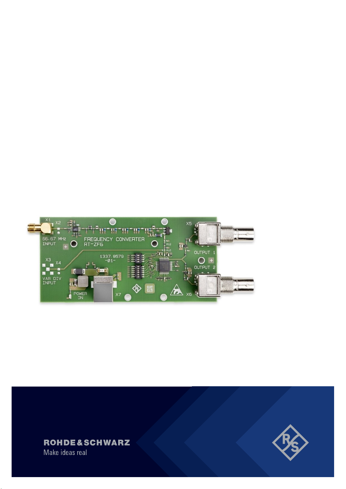
2.2 Board Description
The frequency converter is used in test cases that require an ARB generator.
The converter divides the 125 MHz clock signal of the 1000BASE-T1 PHY by
12.5 so that it can be used as clock reference signal. The reference clock synchronizes the oscilloscope and the ARB generator.
The SMA connector X1 is the input for the 125 MHz signal. The 10 MHz output is
supplied at the BNC connectors X5 and X6. The board is supplied over the USB
connector X7.
3 Connecting the Board
To set up the measurement, perform the following steps:
5Manual 1326.3764.02 ─ 03

R&S®RT-ZF6
1. Check the position of the DIP switches S1 and S2:
a) S1: all switches OFF
b) S2: switches 1, 4 and 5 OFF, switches 2, 3 and 6 ON
2. Connect the input X1 to the clock signal of the 1000BASE-T1 PHY using double-shielded coaxial cables.
3. Connect one of the outputs X5 or X6 to the REF IN port on the rear panel of
the R&S RTO/RTO6/RTP, and the other output to the ARB generator. Use
double-shielded coaxial cables.
4. Connect the USB port X7 of the frequency converter to a USB port type A of
the R&S RTO/RTO6/RTP, or generator, or PC.
A yellow LED lights up if the board is supplied with power.
Contacting customer support
4 Contacting customer support
Technical support – where and when you need it
For quick, expert help with any Rohde & Schwarz product, contact our customer
support center. A team of highly qualified engineers provides support and works
with you to find a solution to your query on any aspect of the operation, programming or applications of Rohde & Schwarz products.
Contact information
Contact our customer support center at www.rohde-schwarz.com/support, or fol-
low this QR code:
Figure 4-1: QR code to the Rohde & Schwarz support page
6Manual 1326.3764.02 ─ 03
 Loading...