

SpycerBox Ultra/Fl ex Hardware Guide (Versio n 3.0)
Storage Solution
SpycerBox
Ultra/Flex
Hardware Guide


SpycerBox Ultra/Flex
Hardware Guide
Introduction
Overview
Installation
Operation
Maintenance
Appendix
Index
1
2
3
4
5
A
I

Hardware Guide Version 3.0 for the SpycerBox Ultra (SpycerBox Ultra II Revision 1.2) and SpycerBox Flex (SpycerBox Flex Revision 1.1)
Copyright © 2012 by Rohde & Schwarz DVS GmbH, Hanover. All rights reserved.
The manuals as well as the soft- and/or hardware described here and all their constituent parts are
protected by copyright. Without the express permission of Rohde & Schwarz DVS GmbH any form
of use which goes beyond the narrow bounds prescribed by copyright legislation is prohibited and
liable to prosecution.
This particularly applies to duplication, copying, translation, processing, evaluation, publishing, and
storing and/or processing in an electronic system.
Specifications and data may change without notice. We offer no guarantee that this documentation
is correct and/or complete. In no event shall Rohde & Schwarz DVS GmbH be liable for any damages
whatsoever (including without limitation any special, indirect or consequential damages, and damages resulting from loss of use, data or profits, or business interruption) arising out of the use of or
inability to use the hardware, software and/or manual materials.
Those parts of this documentation that describe optional software or hardware features usually contain a corresponding note. Anyway, a lack of this note does not mean any commitment from
Rohde & Schwarz DVS GmbH.
DVS and Spycer are registered trademarks of Rohde & Schwarz DVS GmbH. FireWire is a trademark
of Apple Inc., registered in the U.S. and other countries. Linux is a registered trademark of Linus
Torvalds.
Any other product names mentioned in this documentation may be trademarks or registered trademarks of their respective owners and as such are subject to the usual statutory provisions.

Headquarters:
Rohde & Schwarz DVS GmbH
Krepenstr. 8
30165 Hannover
GERMANY
Phone: +49-511-67807-0
Fax: +49-511-630070
E-mail: info.dvs@rohde-schwarz.com
Internet: http://www.dvs.de
Support:
Phone: +49-511-67807-125
Fax: +49-511-371985
E-mail: service.dvs@rohde-schwarz.com


Registration Form
PLEASE SEND TO:
Rohde & Schwarz DVS GmbH
Krepenstr. 8
30165 Hannover
GERMANY
Fax: +49-511-630070
Dear customer,
this product was developed and tested thoroughly. Unfortunately, the possibility of problems and errors can never
be ruled out. To support us in helping you as fast as possible if such a case occurs, please fill in this registration form
and send or fax it to the address on the right.
You may also use our online registration form which can be accessed from the following
internet page: http://www.dvs.de/support/support-login.html
Customer
Name:
Company:
Contact:
Address:
Phone:
Fax:
Vendor:
SpycerBox Ultra/Flex
Serial No.:
Remarks:
Connected devices
(used network connections, connected storages, file systems, etc.)


Contents
C
1 Introduction ...............................................................................1-1
1.1 Overview .................................................................................1-2
1.2 Target Group ...........................................................................1-3
1.3 Conventions Used in this User Guide .....................................1-4
1.4 Safety Instructions .................................................................. 1-5
1.5 Important Notes ......................................................................1-7
2 Overview......................................................................................2-1
2.1 Variants: SpycerBox Ultra and SpycerBox Flex .......................2-2
2.2 Overview of the Front.............................................................. 2-2
2.2.1 The Front of the System .................................................2-2
2.2.2 DVD Drive .....................................................................2-3
2.2.3 HDD LEDs ..................................................................... 2-4
2.2.4 Faceplate ......................................................................2-5
2.2.5 Hard Disk Array ............................................................. 2-6
2.2.6 Operation Items ............................................................. 2-9
2.3 Overview of the Rear.............................................................2-11
2.3.1 The Rear of the System ................................................ 2-11
2.3.2 System Disk Array .......................................................2-12
2.3.3 ATX Connector Panel....................................................2-13
2.3.4 Power Supply ..............................................................2-14
2.3.5 Slot Panel Connectors ..................................................2-15
2.4 Battery Backup Unit .............................................................. 2-17
3 Installation .................................................................................. 3-1
3.1 System Setup .......................................................................... 3-1
3.2 Note about the Network Installation ....................................... 3-2
i

SpycerBox Ultra/Flex Hardware Guide
4 Operation .....................................................................................4-1
4.1 Starting the System .................................................................4-2
4.2 DVS Configuration Tool ...........................................................4-3
4.3 Shutting Down the System .....................................................4-4
5 Maintenance ..............................................................................5-1
5.1 Hard Disk Maintenance ...........................................................5-2
5.1.1 Introduction to RAID ......................................................5-2
5.1.2 Identifying a Broken Hard Disk ........................................5-4
5.1.3 Replacing a Hard Disk ....................................................5-5
5.2 Opening and Closing the Casing .............................................5-8
5.2.1 Opening the Casing ........................................................5-8
5.2.2 Closing the Casing .........................................................5-8
5.3 Fan Maintenance .....................................................................5-9
5.4 Controller Maintenance .........................................................5-12
5.5 Power Supply Maintenance...................................................5-14
5.6 Backup or Recovery of the System Disk ...............................5-16
5.6.1 Creating a Backup Image of the System Disk .................5-16
5.6.2 Restoring the System Disk ............................................5-18
5.7 Removal of the Faceplate ......................................................5-20
A Appendix..................................................................................... A-1
A.1 Troubleshooting ...................................................................... A-2
A.2 Technical Data ........................................................................ A-4
A.2.1 General Technical Data .................................................. A-4
A.2.2 Dimensions .................................................................. A-5
A.3 Packing Instructions ............................................................... A-6
A.4 Conformity Declarations ......................................................... A-8
A.4.1 RoHS Compliance ......................................................... A-8
A.4.2 EC Declaration of Conformity (CE Marking) ..................... A-8
A.4.3 FCC Compliance Statement ........................................... A-8
I Index ...............................................................................................I-1
ii
Introduction
This documentation describes how to use the hardware of the SpycerBox manufactured by DVS. The SpycerBox is a multi-purpose storage
as well as server device delivered with several data management tools.
It is the ideal solution for users at broadcast and post production facilities who want to make the most of their file-based workflows. The
SpycerBox can be used, for example, …
– … as a high-performance automated backup and archiving solu-
tion,
– … as a powerful file server with proxy clip generation, or
– … as an NAS solution for a network.
1
1
2
Together with the hardware of the SpycerBox you also receive the
SpycerBox software, an extended version of DVS’s data management
software Spycer. With the SpycerBox software you can, for instance,
automatically create low-resolution proxy video clips of the content on
the local or a connected storage, defragment an SNFS storage such as
a SAN, or perform scheduled maintenance tasks automatically in your
network.
The SpycerBox hardware uses Linux as its operating system and can be
delivered with various storage capacities. Furthermore, several connection possibilities are optionally available to integrate the system seamlessly into your workflows.
The SpycerBox can be delivered in two hardware variants: SpycerBox
Ultra using 3.5" hard disks (normally 24 pcs.) and providing a storage
capacity of up to 72 TB, and SpycerBox Flex using 2.5" hard disks (normally 48 pcs.) with up to 43.2 TB of storage capacity.
3
4
5
A
I
1-1

SpycerBox Ultra/Flex Hardware Guide
1.1 Overview
This guide informs you about the installation of the SpycerBox hardware, its operation as well as all connection possibilities. Furthermore,
it describes maintenance tasks that you may carry out on your own.
The chapters contain the following information:
Chapter 1 Begins with a short introduction to the Spycer-
Chapter 2 This chapter gives a front and rear overview of
Box, followed by a note regarding the audience
this manual is written for and an explanation of
the conventions used in this manual. Furthermore, it provides safety instructions that you
must adhere to and some important notes that
you should observe.
the system detailing all items, connectors and
interfaces. Additionally, it contains some further information, for example, about the battery backup unit.
Chapter 3 Describes the hardware installation of the DVS
system.
Chapter 4 Explains how to operate the DVS system, i.e.
how to start and shut down the device. Additionally, the DVS Configuration Tool is described briefly.
Chapter 5 Details maintenance work, for example, in case
of a hard disk, fan or power supply unit failure.
Appendix Provides technical details and general informa-
tion about the hardware of the DVS system.
Furthermore, it gives hints how to resolve irregularities during operation.
Index This chapter facilitates the search for specific
terms.
1-2

1.2 Target Group
To use this manual you should know how to handle computer equipment. Furthermore, to connect the DVS system to a network or a SAN
storage you should have experience as a network administrator and
know how to set up the required network connections on the installation site in hard- as well as software.
When performing maintenance tasks on the hardware of the DVS system, you must be qualified to work on, repair and test electrical equipment.
Introduction
1
2
3
4
5
A
I
1-3
SpycerBox Ultra/Flex Hardware Guide
1.3 Conventions Used in this User Guide
The following typographical conventions will be used in this documentation:
Texts preceded by this symbol describe activities that you must per-
form in the order indicated.
– Texts preceded by this symbol are parts of a list.
Texts preceded by this symbol are general notes intended to facilitate work and help avoid errors.
You must pay particular attention to text that follows this symbol to avoid errors and possible resulting damages thereof.
Texts following this symbol you must pay particular attention to to avoid dangers and personal injuries.
“ ” Texts enclosed by quotation marks are references to other man-
uals, guides, chapters, or sections.
Entry Indicates entries to be made at a command line
or an output of a program on the screen
[Key] A key on a keyboard
Keyboard Shortcuts
To perform options or procedures with the keyboard often requires a simultaneous pressing of two keys.
Example:
[Ctrl + F1] If this is given, hold down the [Ctrl] key and
press simultaneously the [F1] key.
1-4

1.4 Safety Instructions
To use the SpycerBox correctly please heed the following:
Please read the following safety instructions carefully before
attempting any installation and/or performing any work on the
SpycerBox hardware.
If the DVS system is not used in compliance with the safety
instructions, the warranty and all resulting liability claims will
be void.
General
The SpycerBox has been built according to the applying safety regulations. To minimize the possibility of a faulty operation of the device all
manuals and guides must be available at all times at the operation site.
Before installing and/or using the DVS system the manuals and guides
delivered with it must be read and observed.
Introduction
1
– Use the DVS system only in apparent good technical order.
– The hardware of the DVS system works with voltages that can be
hazardous to your health. Never work on the system or access its
interior with the power cable(s) being plugged in. Make sure the
power supply is disconnected from the components you intend to
work on.
– Computer hardware contains components that are sensitive to elec-
trostatic discharge. If you touch them without precautionary mea-
sures, they can be destroyed. Use a wrist strap connected to
ground when accessing electronic parts and take care of grounding
the system. Avoid touching the internal components of the DVS
system whenever possible.
– Computer hardware contains components that are sensitive to
changing voltages. Connecting or disconnecting the DVS system to
or from peripheral hardware while any of them is switched on may
damage the hardware. Switch off all peripheral hardware before
connecting or disconnecting anything.
– Use, store and transport the DVS system only in compliance with
the technical data laid out in section “Technical Data” on page A-4.
– If fluids or solid objects get inside the casing, the DVS system must
be disconnected from the power supply immediately. Before using
the DVS system again, it has to be checked by authorized service
personnel.
– Only use a damp tissue without any cleaning agents to clean the
casing.
– The DVS system must not be misused, abused, physically dam-
aged, neglected, exposed to fire, water or excessive changes in the
climate or temperature, or operated outside maximum rating.
– Do not perform any changes or extensions to the DVS system
whatsoever.
2
3
4
5
A
I
1-5

SpycerBox Ultra/Flex Hardware Guide
Transportation
The SpycerBox is a very sensitive device. Especially the hard disks of
the system must be handled with great care. Therefore, observe in case
of transportation:
– Handle the DVS system with great care.
– Always use the original packing or a similar structured packing for
transportation as detailed in section “Packing Instructions” on
page A-6.
– Avoid shocks or vibrations during transport. For longer distances it
is recommended to use a lifting truck.
– Keep the DVS system as a transportation good dry.
– In the warranty period you have to keep the original packing and
use it in case of transportation.
Environmental Conditions
For error-free working and a long service life the SpycerBox needs
some basic environmental conditions:
– Do not expose the DVS system to sources of heat, such as direct
sunlight or a radiator.
– Do not cover or obstruct the ventilation holes of the system.
– When installing the DVS system in a rack, take care that warmed up
air is conducted to the rear of the rack and properly vented away.
– Avoid areas with high humidity or dust. Best operating conditions
are given in an air-conditioned site.
– Do not expose the DVS system to strong electric or magnetic fields.
– Avoid areas where the DVS system will be subject to vibrations or
shocks.
1-6
1.5 Important Notes
The following provides information about warranty, a note about the
conformity of the product and some other general information.
Warranty Information
This product is warranted to be free of defects in materials and workmanship for a period of one year from the date of purchase. DVS extends this Limited Warranty to the original purchaser.
You have to keep the original packing and use it in case of
transportation. Otherwise this warranty will be void.
In the event of a defect or failure to confirm to this Limited Warranty,
DVS will repair or replace the product without charge. In order to make
a claim under this Limited Warranty, the purchaser must notify DVS or
their representative in writing of the product failure. In this Limited Warranty the customer must upon DVS’s request return the product to the
place of purchase or send the defective device to a given address for
the necessary repairs to be performed. In the warranty period the customer must keep the original packing and pack the DVS product in it in
case of a product return. If the customer is not satisfied with the repair,
DVS will have the option to either attempt a further repair, exchange the
product or refund the purchase price.
Introduction
1
2
3
This warranty does not cover:
– Products not developed by Rohde & Schwarz DVS GmbH.
– Products not used in compliance with the safety instructions
detailed in section “Safety Instructions” on page 1-5.
– Products on which warranty stickers or product serial numbers
have been removed, altered or rendered illegible.
– The costs of installations, removals, transportations, or reinstalla-
tions.
– Costs for transportation damages.
– Damages caused to any other item.
– Any special, indirect or consequential damages, and damages
resulting from loss of use, data or profits, or business interruption.
Declaration of Conformity
This product has been tested according to
the applying national and international directives and regulations. Further information
about this can be found in section “Conformity Declarations” on page A-8.
4
5
A
I
1-7
SpycerBox Ultra/Flex Hardware Guide
Product Disposal (B2B)
Used electrical and electronic products should not be disposed of with general household waste. At the end of its
service life you may return the DVS product after appropriate prior notification to either your local distributor or
DVS in Germany. DVS will then take the device free of
charge to a waste disposal organization which will recycle and reuse it environmental friendly.
General Notes
Please observe the following general important notes:
Leave about 10 to 15% of the overall main storage capacity
empty of data for performance reasons.
Your DVS system has been tested thoroughly and is very reliable. However, because of the vast amount of third-party software available, its reactions on the installation of such could
not be tested. The installation of third-party software may disrupt the real-time capability and/or limit the functionality of
your system.
1-8

Overview
This chapter provides a detailed overview of the hardware of the DVS
system. First the different hardware variants of system will be explained. After this it will be shown in a front and a rear view and all its
parts and connectors will be described. The chapter will be concluded
with a description of the battery backup unit installed inside the system.
2
1
2
3
4
5
A
I
2-1
SpycerBox Ultra/Flex Hardware Guide
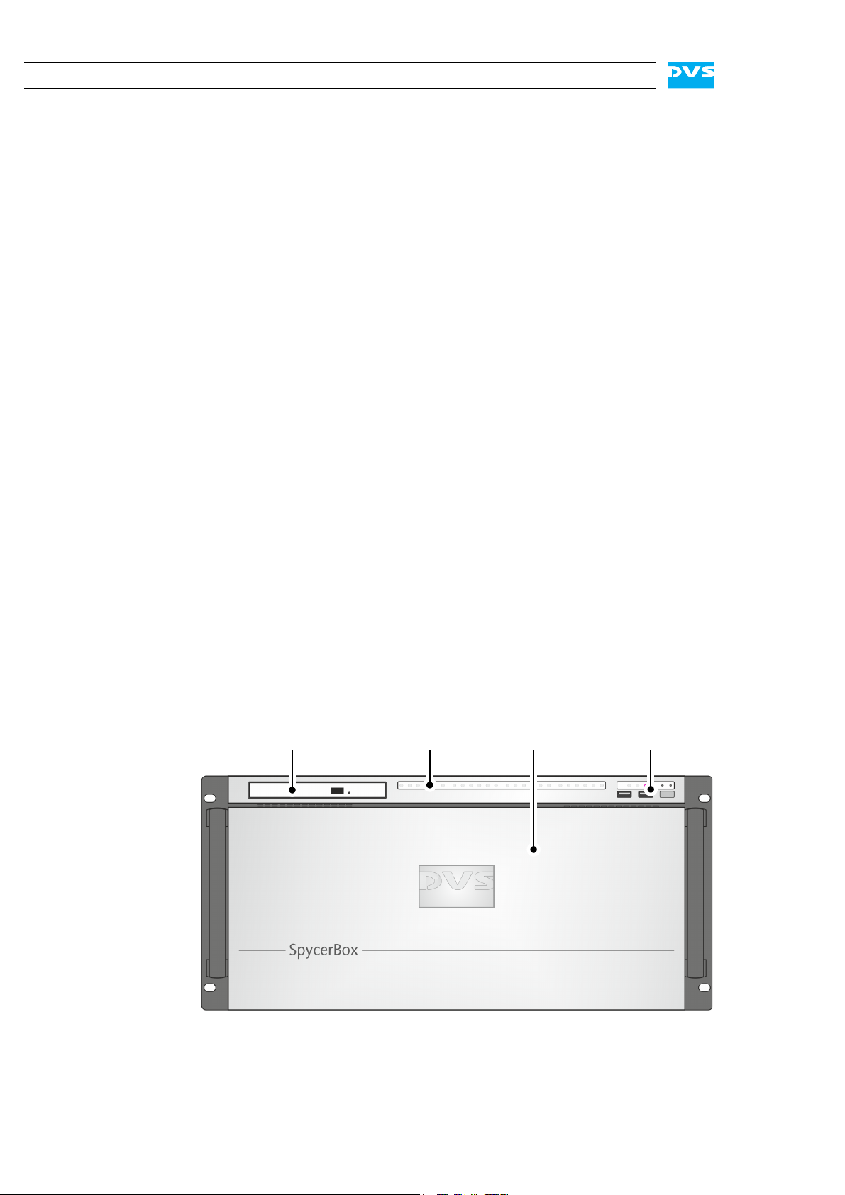
DVD drive
faceplate/
HDD LEDs operation items
hard disk array
2.1 Variants: SpycerBox Ultra and SpycerBox Flex
The SpycerBox can be delivered in two different hardware variants depending on, for example, the amount of the storage or the performance
that is required. The following variants are available:
– SpycerBox Ultra using 3.5" hard disks (normally 24 pcs.) and pro-
viding a storage capacity of up to 72 TB.
– SpycerBox Flex using 2.5" hard disks (normally 48 pcs.) for up to
43.2 TB of storage capacity.
Apart from the hard disk array where the hard disks are installed (see
section “Hard Disk Array” on page 2-6) the two variants are in most respects identical. Whereever required the specialities of these variants
will be detailed in this document.
2.2 Overview of the Front
This section gives an overview of the front of the DVS system. After an
overall overview of the front the DVD drive is described first, followed
by details about the HDD LEDs. After this the faceplate and the hard
disk array of the system as well as the operation items will be explained.
2.2.1 The Front of the System
This section provides an overview of the front of the system:
2-2
Figure 2-1: Overview of the front
Overview
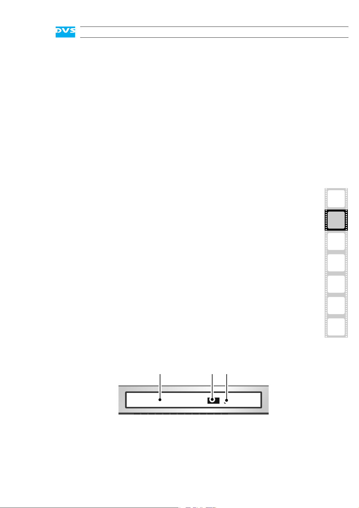
DVD tray DVD eject emergency eject
DVD drive The DVD drive can be used, for example, for soft-
ware installations. Further information about the
DVD drive can be found in section “DVD Drive” on
page 2-3.
HDD LEDs The upper part of the front is equipped with LEDs
that indicate the statuses (activities) of the hard
disks of the hard disk array. Further information
about the LEDs and their meaning can be found in
section “HDD LEDs” on page 2-4.
faceplate/
hard disk array
operation items With the operation items the system can be con-
2.2.2 DVD Drive
The system is equipped with a DVD drive which can be used for service
purposes or to install additional software. It also provides burning capability.
The faceplate covers the hard disk array. If you
need access to one of the hard disks, for example,
to replace it, it can be lifted. The faceplate will be
described in more detail in section “Faceplate” on
page 2-5.
The hard disk array contains the main storage hard
disks which can be used to store video, audio or
backup material. All disks can be replaced easily in
case of failure. The disk array is described in more
detail in section “Hard Disk Array” on page 2-6.
trolled (e.g. turned on or off). Additionally, they offer some LEDs that allow you to assess the state of
the DVS system as well as USB connectors for an
easy connectivity of additional devices such as
memory sticks. Further information about the operation items can be found in section “Operation
Items” on page 2-9.
1
2
3
4
5
A
I
Figure 2-2: Overview of DVD drive
DVD tray The DVD tray holds the CD or DVD.
2-3
SpycerBox Ultra/Flex Hardware Guide
A
1
BCD
234 1234 1234 1234
1111
2222
3333
4444
LEDs:
hard disks:
5 5 5 5
5555
ABCD
66 6 6
6666
DVD eject Opens the DVD tray when the system is turned
emergency eject You can open the DVD tray with the system
For further information regarding the operation of the drive, please refer
to the original manufacturer’s documentation.
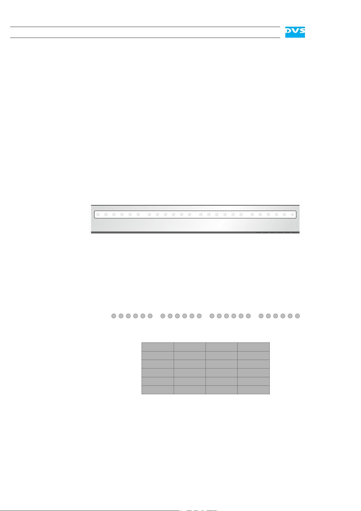
2.2.3 HDD LEDs
The HDD LEDs show the statuses (activities) of the hard disks of the
hard disk array (see section “Hard Disk Array” on page 2-6). They can
be seen only when they are flashing because they are located behind
the white strip and thus not visible when off.
on.
cut from power: Insert a thin, pointed object
into the emergency eject hole. Then the DVD
tray opens.
Figure 2-3: HDD LEDs
SpycerBox Ultra
For the SpycerBox Ultra each LED represents one hard disk of the hard
disk array:
Figure 2-4: HDD LEDs and the hard disk array (SpycerBox Ultra)
Starting from the left, the first six LEDs display the accesses to hard
disks in the very left column of the array, the second six LEDs show the
state of the hard disks of the second column, and so on.
2-4
Overview
A
1
BC
234781256783456
23344
LEDs:
hard disks:
5 3 1 7
5
5
8
8
A
86 4 2
667
7
112
2334455
8
8
667
7
112
2334455
8
8
667
7
112
BC
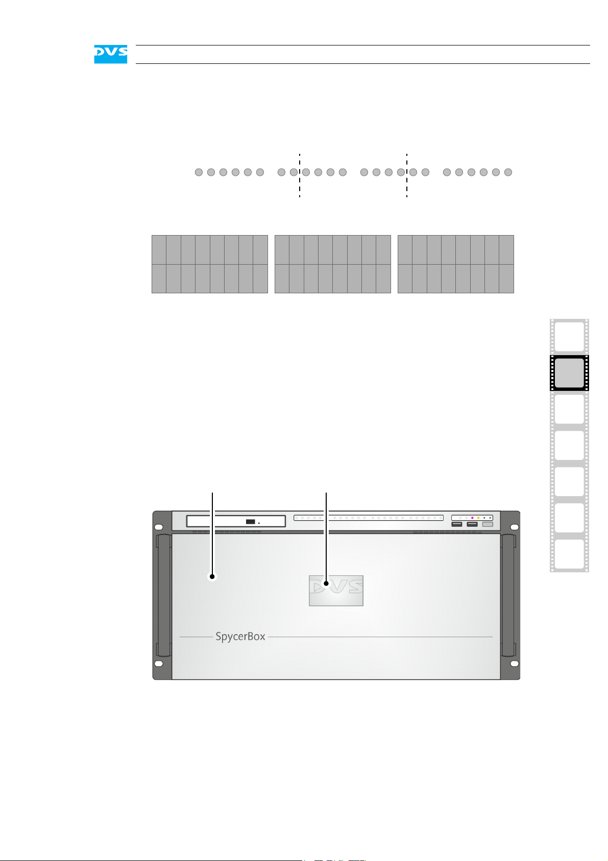
faceplate backlit DVS logo
SpycerBox Flex
For the SpycerBox Flex the state of every two hard disks of the hard
disk array is displayed by one LED.
Figure 2-5: HDD LEDs and the hard disk array (SpycerBox Flex)
Starting from the left, the first eight LEDs display the accesses to the
hard disks in the first eight columns of the hard disk array (16 hard
disks), the second eight LEDs show the state of the second eight columns, and so on.
2.2.4 Faceplate
The faceplate covers the hard disks of the hard disk array.
1
2
3
4
5
A
I
Figure 2-6: Overview of the faceplate
The faceplate is built with an integrated backlit DVS logo which indicates the state of the system, i.e. its power-on status: If the DVS logo
is illuminated, the power is turned on; if not, the power is turned off.
2-5
 Loading...