

Page 1
R&S®CHM
System Status Monitoring
Manual
(;ÝSE2)
1179352102
Version 04
Page 2

This document describes the R&S®CHM system status monitoring software (3067.6545.02).
© 2022 Rohde & Schwarz GmbH & Co. KG
Muehldorfstr. 15, 81671 Muenchen, Germany
Phone: +49 89 41 29 - 0
Email: [email protected]
Internet: www.rohde-schwarz.com
Subject to change – data without tolerance limits is not binding.
R&S® is a registered trademark of Rohde & Schwarz GmbH & Co. KG.
Trade names are trademarks of the owners.
1179.3521.02 | Version 04 | R&S®CHM
Throughout this document, products from Rohde & Schwarz are indicated without the ® symbol, i.e. R&S® is abbreviated as R&S.
Page 3

R&S®CHM
Contents
Contents
1 Welcome to R&S CHM........................................................................... 5
1.1 Key features...................................................................................................................5
1.2 Documentation overview..............................................................................................5
1.2.1 Manual............................................................................................................................ 6
1.2.2 Brochure..........................................................................................................................6
1.2.3 Release notes and open source acknowledgment (OSA).............................................. 6
2 Introduction............................................................................................ 7
3 Monitoring the system status............................................................... 9
3.1 Starting the R&S CHM web GUI................................................................................... 9
3.2 Obtaining a status overview...................................................................................... 10
3.3 Focusing on specific components............................................................................ 11
3.4 Displaying status details............................................................................................ 13
3.5 Verifying status history.............................................................................................. 13
3.6 Customizing the web GUI...........................................................................................15
3.6.1 Changing the theme......................................................................................................15
3.6.2 Managing user-defined navigation items...................................................................... 15
4 System administration.........................................................................18
4.1 Installing R&S CHM.....................................................................................................18
4.1.1 Installing the R&S CHM host without LSCM................................................................. 19
4.1.2 Installing R&S CHM agents...........................................................................................20
4.1.3 Firewall rules................................................................................................................. 21
4.2 Deploying certificates on R&S CHM agents............................................................. 21
4.2.1 Using self-singed certificates........................................................................................ 22
4.2.2 Using CA-signed certificates......................................................................................... 25
4.2.3 Removing self-signed certificates................................................................................. 25
4.3 Configuring status monitoring...................................................................................26
4.3.1 Introduction to the YAML syntax....................................................................................26
4.3.2 Changing the configuration........................................................................................... 28
4.3.3 Configuring hosts.......................................................................................................... 29
4.3.4 Configuring R&S CHM web users.................................................................................37
3Manual 1179.3521.02 ─ 04
Page 4

R&S®CHM
4.3.6.1 Configuring the chmrd service...................................................................................... 44
Contents
4.3.5 Managing password identifiers......................................................................................41
4.3.6 Configuring R&S RAMON for monitoring...................................................................... 42
4.4 Configuring services.................................................................................................. 47
4.4.1 Frequent keys............................................................................................................... 47
4.4.2 Hardware services........................................................................................................ 51
4.4.3 Software services..........................................................................................................63
4.5 YAML configuration examples................................................................................... 73
4.5.1 R&S CHM host configuration........................................................................................ 73
4.5.2 Linux host configurations.............................................................................................. 75
5 Troubleshooting................................................................................... 77
5.1 Troubleshoot not running services...........................................................................77
5.2 R&S CHM shows message "Wrong SNMP PDU digest"..........................................77
5.3 R&S CHM web GUI shows 404 error......................................................................... 77
5.4 Contacting customer support....................................................................................78
Glossary: Abbreviations and terms................................................... 79
Glossary: Specifications..................................................................... 83
List of keys........................................................................................... 84
Index......................................................................................................85
4Manual 1179.3521.02 ─ 04
Page 5

R&S®CHM
Welcome to R&S CHM
Documentation overview
1 Welcome to R&S CHM
The R&S CHM software monitors status information from various system components
that are connected to the network. The web-based user interface visualizes system
state parameters, and lets you monitor and troubleshoot connected and configured
Rohde & Schwarz instruments, hosts and SNMP devices.
Target audience
The manual familiarizes you with the functions and operation of R&S CHM. In addition,
it provides you with the information about configuration of monitoring services.
The contents are therefore intended for operators and administrators of R&S CHM.
●
Operators: Monitor configured hosts and services with restricted permissions.
●
Administrators: Monitor configured hosts and services with extended permissions.
●
System administrators:
Install and configure R&S CHM on the R&S CHM host.
These tasks require root user access. System administrators require elevated privileges to complete their tasks. It is assumed that system administrators already
have comprehensive knowledge of system setup and configuration.
● Key features..............................................................................................................5
● Documentation overview...........................................................................................5
1.1 Key features
R&S CHM system status monitoring provides the following high-level features:
●
Run on a security-enhanced Linux distribution (SELinux)
●
Run on a hardened operating system according to DISA STIGs. For information,
see https://public.cyber.mil/stigs/.
●
Run unattended for a long period of time
●
Continuously monitor the status of hosts and services, e.g. used disk space
●
Allow configuration of device-specific monitoring services
●
Reduce down-time of system components
●
Troubleshooting of problems
●
Encrypted communication between R&S CHM and monitored hosts
●
Secure password handling
1.2 Documentation overview
This section provides an overview of the R&S CHM user documentation.
5Manual 1179.3521.02 ─ 04
Page 6

R&S®CHM
Welcome to R&S CHM
Documentation overview
1.2.1 Manual
The manual is part of the R&S CHM user documentation. It is provided as PDF and as
help on the R&S CHM web GUI.
The manual introduces to the software and describes how to set up and start working
with the product. Also, it provides a comprehensive description of the R&S CHM functions and how you set up and configure R&S CHM.
The manual is available for download or for immediate display on the internet.
To show the help on the R&S CHM web GUI
► On the left navigation area of the R&S CHM web GUI, select "System" > "Manual".
The help opens in the R&S CHM web GUI.
1.2.2 Brochure
The brochure provides an overview of the software and deals with the specific characteristics.
See www.rohde-schwarz.com/brochure-datasheet/chm
1.2.3 Release notes and open source acknowledgment (OSA)
The release notes list new features, improvements and known limitations of the current
software version.
The open-source acknowledgment document provides verbatim license texts of the
used open-source software.
6Manual 1179.3521.02 ─ 04
Page 7
R&S®CHM
Introduction
2 Introduction
The R&S CHM system status monitoring software provides an integrated, system-wide
solution to collect status information continuously in a local area network (LAN). The
software continuously performs checks for monitored hosts and services and evaluates
the results. If R&S CHM detects an error condition, it creates an alert. The following
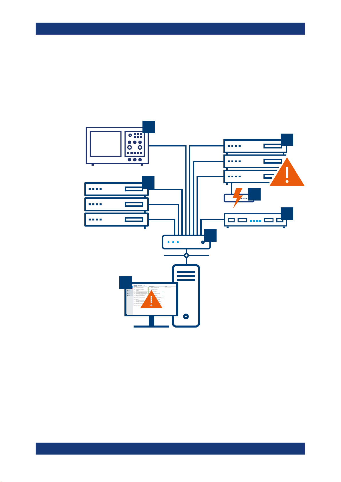
figure provides an overview of a monitored system.
4
5
3
1
Figure 2-1: R&S CHM - status monitoring overview
1 = Computer with web-based user interface
2 = Network component (router, switch)
3 = Server hardware
4 = Rohde & Schwarz device
5 = Server hardware with error condition
6 = Uninterruptible power supply with error condition
7 = R&S CHM host that runs the status monitoring software
6
7
2
The R&S CHM software runs on a Linux server (7) and the web-based user interface
runs on a standard computer (1).
7Manual 1179.3521.02 ─ 04
Page 8
R&S®CHM
Introduction
R&S CHM can fetch data from all connected and configured system components (1 to
7). Therefore, the operational state of the system is always under control. The down-
time periods, due to maintenance operations or hardware failures, are reduced to a
minimum.
Lifetime of monitoring data
All monitoring data is retained for 90 days. Older data is purged from the database.
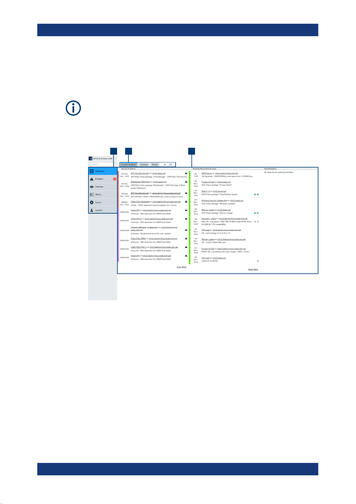
To monitor status information, system operators and administrators use the browserbased graphical user interface, in the following named as "web GUI".
1 32
Figure 2-2: Web GUI for status monitoring
1 = Main filter categories
2 = Additional filter categories
3 = Main area for problem monitoring
For configuration of R&S CHM from any client in the LAN, system administrators can
use an SSH client, such as PuTTY.
How to continue?
The next steps depend on your role as mentioned under "Target audience" on page 5.
●
Monitor system status information on the web GUI (operators)
Continue with Chapter 3, "Monitoring the system status", on page 9.
●
Install and configure R&S CHM (administrators, integrators)
These tasks address system administrators and software integrators:
– Chapter 4.1, "Installing R&S CHM", on page 18
– Chapter 4.3, "Configuring status monitoring", on page 26
8Manual 1179.3521.02 ─ 04
Page 9

R&S®CHM
Monitoring the system status
Starting the R&S CHM web GUI
3 Monitoring the system status
Here, you can find the information for accessing the web GUI where you carry out all
status monitoring tasks. The web GUI provides numerous filters that you can use to
monitor your system efficiently.
The web GUI only shows the hosts and services that your system administrator has
configured for monitoring. For information about service configuration, see Chapter 4.4,
"Configuring services", on page 47.
● Starting the R&S CHM web GUI............................................................................... 9
● Obtaining a status overview....................................................................................10
● Focusing on specific components........................................................................... 11
● Displaying status details..........................................................................................13
● Verifying status history............................................................................................13
● Customizing the web GUI....................................................................................... 15
3.1 Starting the R&S CHM web GUI
You can access R&S CHM web GUI using a standard web browser on any computer
that is connected to the LAN. We recommend using a current version of Microsoft
Edge or Google Chrome.
To start the GUI
1. Open your web browser.
2. In the address bar, type the IP address of the R&S CHM host, e.g. 10.100.120.12.
The browser displays a registration page.
3. Enter your credentials. This step depends on the configured user authentication
method.
● With configured LDAP user authentication, log in with your network creden-
tials or ask your system administrator for details.
Figure 3-1: Web GUI - LDAP sign-in page
9Manual 1179.3521.02 ─ 04
Page 10

R&S®CHM
Monitoring the system status
Obtaining a status overview
See also: Chapter 4.3.4, "Configuring R&S CHM web users", on page 37
● For configured local user authorization, use one of the preconfigured local
users.
Figure 3-2: Web GUI - local user sign-in page
– Administrator: admin, password chmadmin
– Operator: operator, password chmoperator
Change the password after initial login. Use a unique and strong password that
complies with the security policies in your company.
The browser displays the "Dashboard" view.
Continue with Chapter 3.2, "Obtaining a status overview", on page 10.
3.2 Obtaining a status overview
For obtaining an overview of the current status of all configured hosts and services,
you can start from the "Dashboard" view. This view provides specific filters that you
can use to focus only on relevant status information, e.g. critical problems.
A host is a configured SNMP device or an agent, i.e. a Windows or Linux host. A service is a monitored element of a host.
10Manual 1179.3521.02 ─ 04
Page 11
R&S®CHM
Monitoring the system status
Focusing on specific components
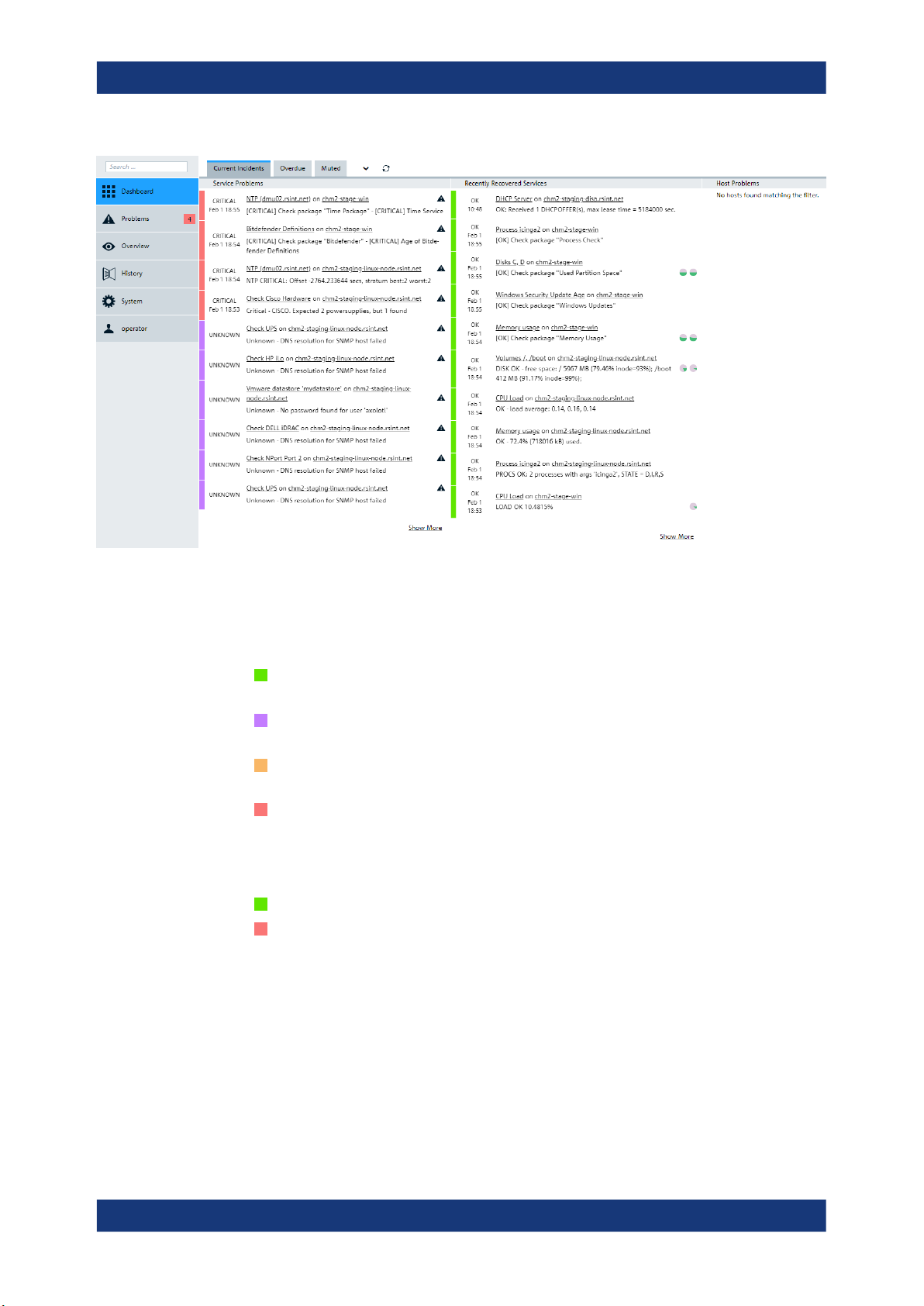
Figure 3-3: Dashboard view
Problem severity
Four status levels indicate the severity of detected service problems:
●
OK (green): The service is up and running; R&S CHM does not detect a prob-
lem.
●
UNKNOWN (purple): R&S CHM cannot detect the status of the service, e.g. due
to LAN interruptions. Check for connection or configuration problems.
●
WARNING (orange): The service is running, but exceeds the configured thresh-
old. Check for problem details and report them to your administrator.
●
CRITICAL (red): The service exceeds the critical threshold and thus has severe
problems. Immediately check for problem details and report them to your administrator.
Two status levels indicate the severity of detected host problems:
●
OK (green): The host is up and running; R&S CHM does not detect a problem.
●
CRITICAL (red): The host is down. Immediately check for problem details and
report them to your administrator.
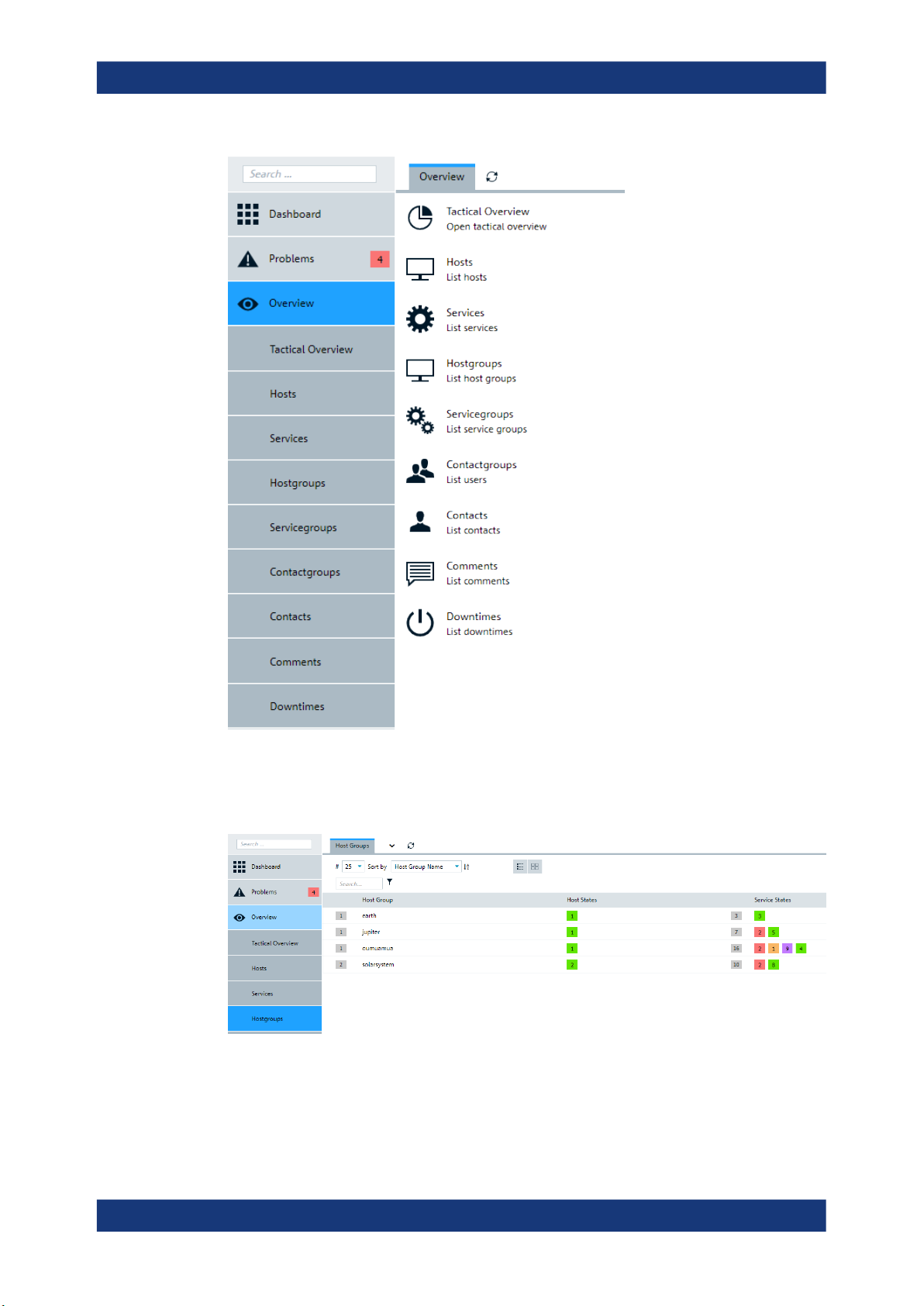
3.3 Focusing on specific components
For accessing the current state of specific system components, you can start from the
"Overview" view. This view provides specific filters that you can use to display only relevant resources or groups of resources.
11Manual 1179.3521.02 ─ 04
Page 12
R&S®CHM
Monitoring the system status
Focusing on specific components
Figure 3-4: Overview view
For example, select the "Hostgroups" to check the state of configured groups of host
from a specific location.
Figure 3-5: Host groups and their states
12Manual 1179.3521.02 ─ 04
Page 13
R&S®CHM
Monitoring the system status
Verifying status history
3.4 Displaying status details
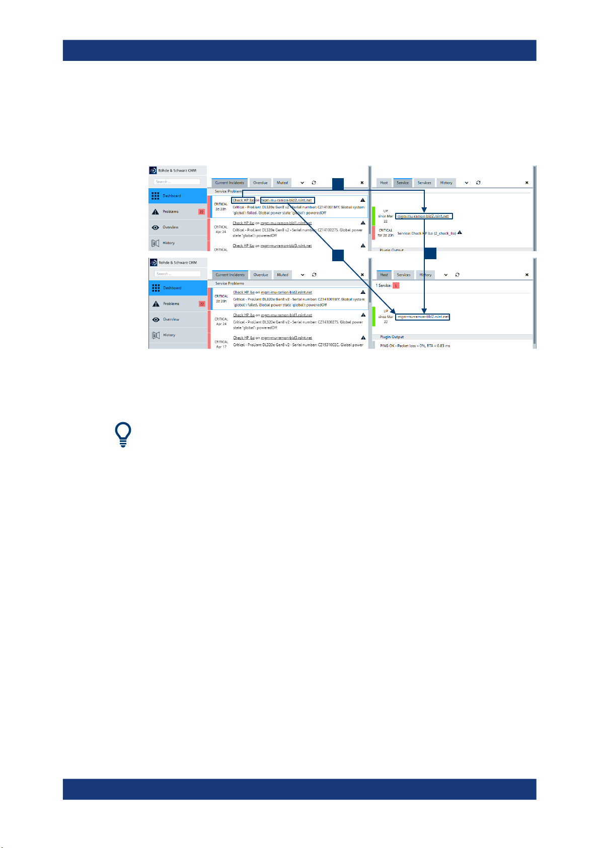
For displaying status details of a defective resource, you follow the links of this
resource. There are different detail levels that you can access.
1
Figure 3-6: Navigating on the web GUI
1 = Show detailed information for selected service on related host.
2, 3 = Show detailed information for selected host.
Use the "Back" function of the web browser to return to the previous page.
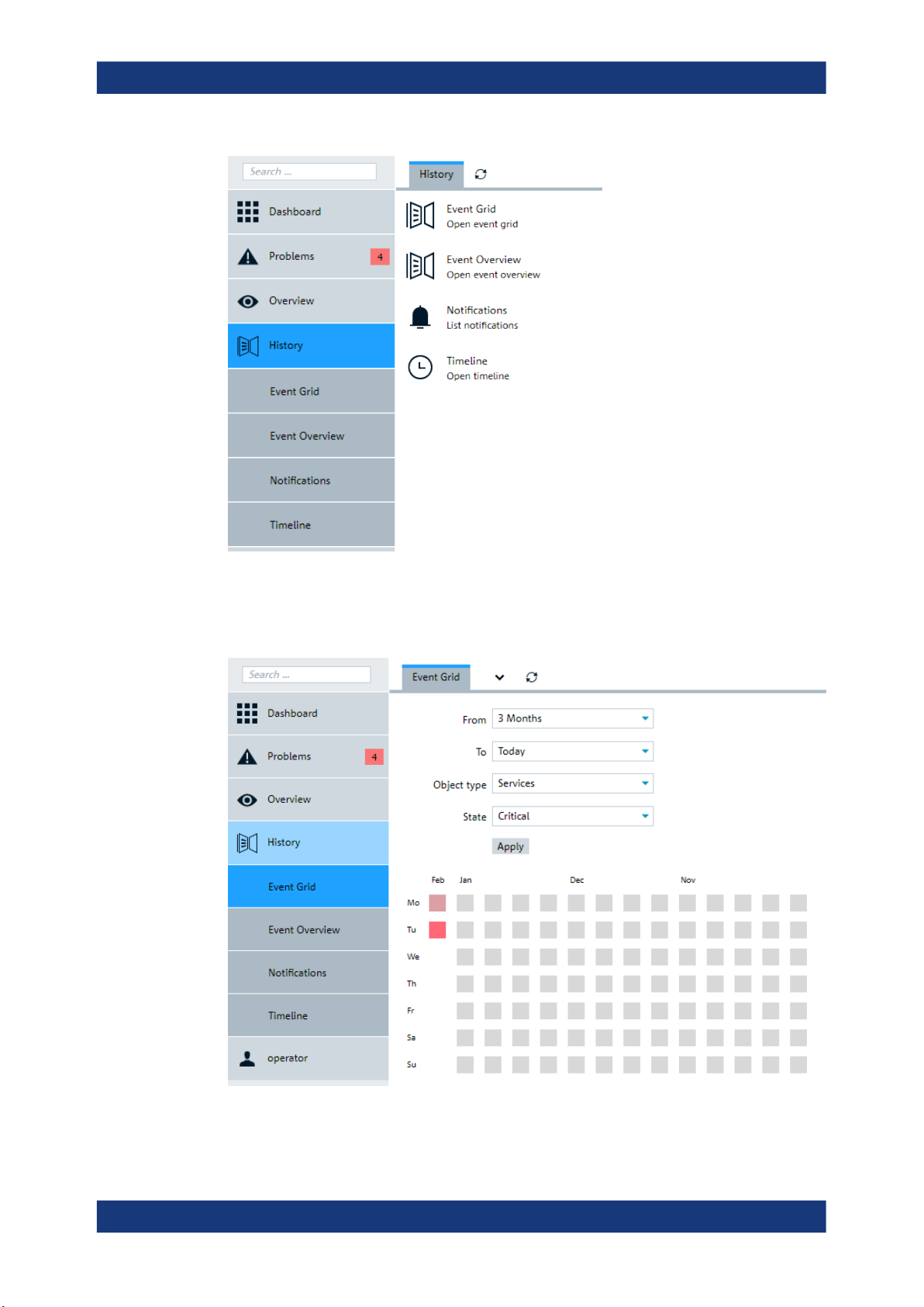
3.5 Verifying status history
For obtaining an overview of the system status over time, select the "History" view.
3
2
13Manual 1179.3521.02 ─ 04
Page 14
R&S®CHM
Monitoring the system status
Verifying status history
Figure 3-7: History of alerts
For example, you can display the alerts from the past in a grid of months and days and
thus you can identify problem accumulations by time.
Figure 3-8: Event grid - summary history of alerts
14Manual 1179.3521.02 ─ 04
Page 15

R&S®CHM
Monitoring the system status
Customizing the web GUI
3.6 Customizing the web GUI
You can customize the following settings of the web GUI to suit your needs.
3.6.1 Changing the theme
The default theme is light, which is suitable in bright surroundings. The dark theme
uses a black background and light labeling and is suitable in darkish surroundings.
To apply the dark theme
Starting situation: "Operator" > "My Account"
1. On the left menu, select "My Account".
The "Preferences" view opens.
2. On the "My Account" tab, set the "Theme" to "rs-company-theme/dark".
3. Save the settings to take the changes effect. You can apply the setting for the current session or make the setting permanent until you change it again.
The theme changes to dark.
3.6.2 Managing user-defined navigation items
You can create additional, user-defined navigation items on the web GUI. These items
can help you focus on specific hosts or services if necessary.
To create a navigation item
Use this procedure to prepare navigation item that you can use to assign specific navigation items to. You can create menu items or items that are shown on the tabs of a
menu item, e.g. on the "Host" tab.
Prerequisite: If you want to create a host or service action, you need the link to this
host or service. You can copy the link from already existing hosts or services before
you continue. Right-click the host or service, and then select "Copy link address".
Starting situation: "Operator" menu > "My Account" dashboard
15Manual 1179.3521.02 ─ 04
Page 16
R&S®CHM
Monitoring the system status
Customizing the web GUI
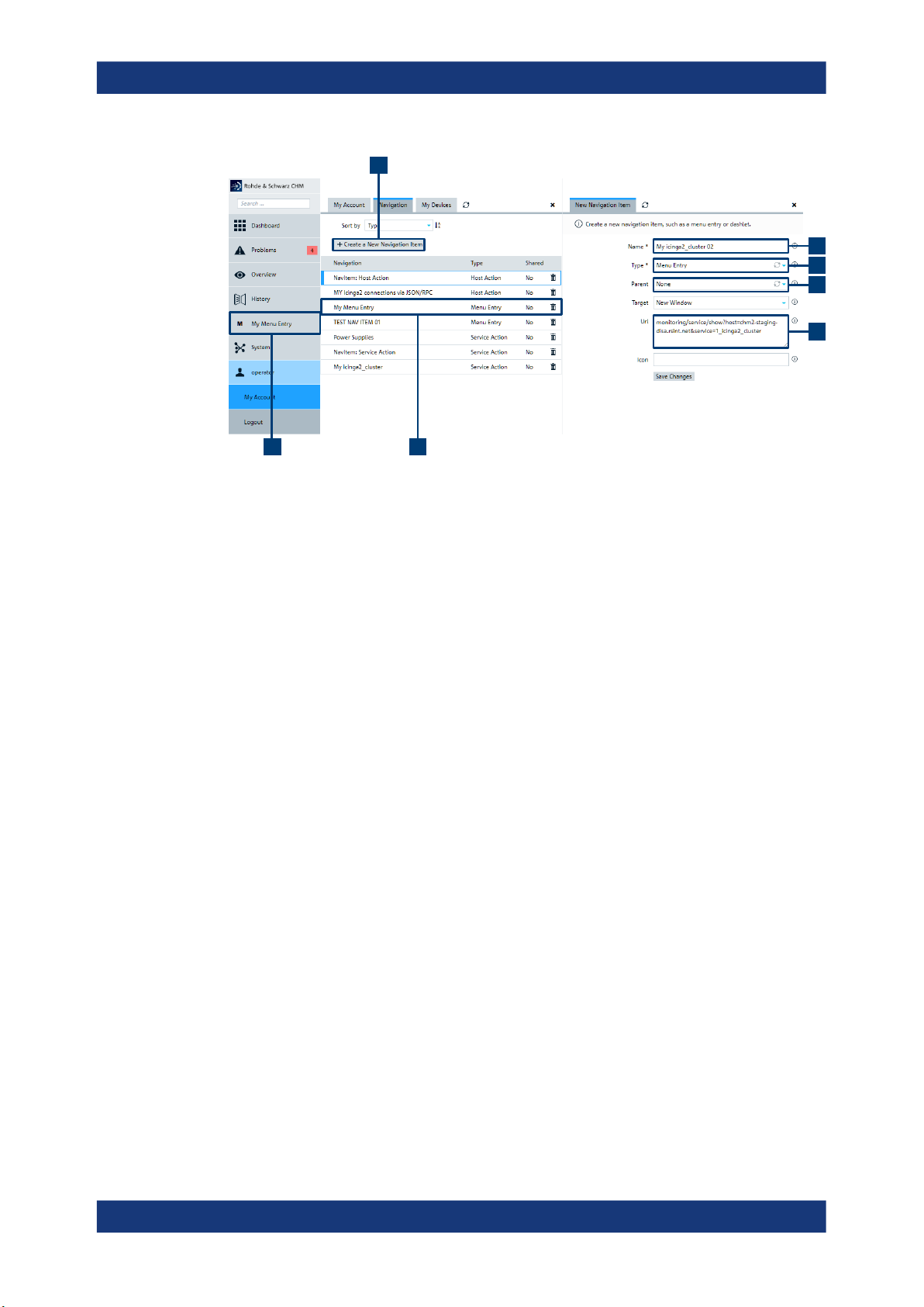
A
B
C
D
E
FG
Figure 3-9: Creating and configuring a navigation item
1. On the "Navigation" tab, select "Create a New Navigation Item" (A).
2. Provide the necessary information for the navigation item.
● "Name" (mandatory) (B): Specify the name of the menu item.
● "Type" (mandatory) (C): Select "Menu Entry" to add the navigation item to the
main menu.
"Host Action" and "Service Action" assigns a navigation item to one of the predefined "Host" or "Services" dashboards.
● "Parent" (optional) (D): Select "None" to make this entry a main menu entry.
You can also select from already existing user-defined menu items.
● "Url": The link to a host or service. If you specify a main menu entry, an "Url" is
not necessary. But if you want to add a host or service, you need a link here.
The new navigation item is successfully created, see example "My Menu Entry" (F,
G).
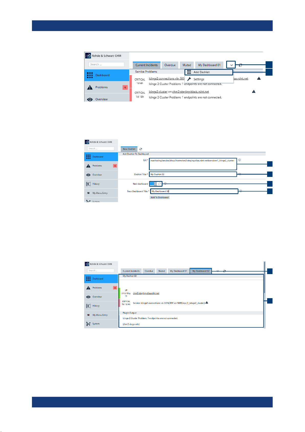
To create dashlets
A dashlet represents an area on a dashboard. Dashlets are assigned to predefined or
user-defined dashboards. The web GUI already shows predefined dashlets, e.g. the
"Service Problems" dashlet on the "Dashboard" view > "Current incidents" dashboard.
You can add more user-defined dashlets to suit your needs. In this procedure, we create a dashboard with dashlet on the "Dashboard" view.
Starting situation: "Dashboard" view
1. Select the down arrow (A) next to already available dashboards.
16Manual 1179.3521.02 ─ 04
Page 17
R&S®CHM
Monitoring the system status
Customizing the web GUI
A
B
Figure 3-10: Adding a dashlet
2. From the list, select "Add Dashlet".
3. On the "New Dashlet" tab, specify the following:
C
D
Figure 3-11: Configuring a dashlet
● "Url" (
C): The link to a host or service.
● "Dashlet Title" (mandatory) (D): Enter the name of the dashlet.
● "New dashboard" (optional) (E, F): If selected, adds the dashlet to a new dash-
board. Enter the name fo the dashboard.
You have added a user-defined dashboard and a user-defined dashlet.
E
F
G
H
Figure 3-12: User-defined dashboard and dashlet on the web GUI
G = Dashboard
H = Dashlet
17Manual 1179.3521.02 ─ 04
Page 18

R&S®CHM
4 System administration
The tasks within the following chapters are typically in responsibility of system administrators.
4.1 Installing R&S CHM
Software installation is divided into these main parts:
●
R&S CHM host installation
The R&S CHM host software runs on CentOS. Use the Rohde & Schwarz life-cycle
software manager (LCSM) for installation. If LCSM is not available, follow the
description in Chapter 4.1.1, "Installing the R&S CHM host without LSCM",
on page 19.
●
R&S CHM agent installation
The agent software runs on monitored Windows- and CentOS Linux-based computers.
– "To install Windows agents" on page 20
– "To install CentOS Linux agents" on page 21
System administration
Installing R&S CHM
Before you start installation, review the minimum hardware and software requirements
for the R&S CHM host and the agents.
Hardware and software requirements
You can install the R&S CHM host software on a server or a virtual machine (VM).
Ensure that the R&S CHM host meets the minimum requirements listed in the following
table. Keep in mind that the requirements increase with an increasing number of monitored system components and services.
Table 4-1: Requirements for R&S
Component Minimum requirements
CPU 2 cores with 2 GHz
HDD 50 GByte
RAM 2 GByte
LAN adapter 1 Gbit/s, RJ-45 connector
Operating system CentOS Linux v7 (2009) distribution
Table 4-2: Requirements for Windows agents
Component Minimum requirements
CHM hosts and CentOS Linux agents
Optional with hardening according to DISA standard
CPU 2 cores with 2 GHz
HDD 50 GByte
18Manual 1179.3521.02 ─ 04
Page 19

R&S®CHM
System administration
Component Minimum requirements
RAM 2 GByte
Operating system Windows 10 build 1809 and later
● Installing the R&S CHM host without LSCM........................................................... 19
● Installing R&S CHM agents.....................................................................................20
● Firewall rules...........................................................................................................21
4.1.1 Installing the R&S CHM host without LSCM
The R&S CHM host runs on CentOS. If you do not have a host running this operation
system, we recommend downloading the CentOS minimal version from the internet.
To install CentOS Linux
For comprehensive installation instructions, visit https://docs.centos.org/en-US/centos/
install-guide/. In the following procedure, only the main steps are provided.
1. Visit the CentOS homepage at https://www.centos.org/download/.
Installing R&S
CHM
2. Download an ISO image of the CentOS Linux v7 (2009) that suits the hardware
architecture of your host, for example x86_64 for an Intel 64-bit server.
3. Prepare the installation source.
You can select from various options:
● If you need a bootable physical media, prepare a DVD or a USB flash drive.
● If you install CentOS in a virtual machine, configure the virtual machine with at
least the minimum requirements listed in Table 4-1. You can directly select the
ISO image as startup disk on your HDD.
● If needed, you also can save the ISO image from a location on the network and
boot it using NFS, FTP HTTP or HTTPS access methods.
4. Boot the installation media or ISO image.
5. Select "Install " in the boot menu and press [Enter].
Anaconda, the CentOS installer starts.
6. Follow the instructions on the screen.
All installation options are properly configured, such as language, region, keyboard
layout, date and time.
7. On the "INSTALLATION SUMMARY" screen, select "Begin Installation".
Installation of CentOS starts.
CentOS is installed on the host and ready for operation.
19Manual 1179.3521.02 ─ 04
Page 20

R&S®CHM
System administration
Installing R&S
To install the R&S CHM host software
1. Ask your Rohde & Schwarz sales representative or application engineer for providing the R&S CHM host software package.
2. Copy the chm-<version>.tar.gz archive to the R&S CHM host > /root/. For
example, you can use WinSCP for this task.
3. Log in to the R&S CHM server, e.g. using SSH.
4. Change to the directory where the chm-<version>.tar.gz file resides.
5. Unpack the archive.
# tar xfvz chm-*.tar.gz
6. Execute the install script.
# ./install-chm-server
Installation takes a while. Wait until the Completed message is shown.
The R&S CHM host is up and running.
Continue with Chapter 4.3.2, "Changing the configuration", on page 28.
CHM
4.1.2 Installing R&S CHM agents
The agent is a program that runs remotely on a Windows or Linux computer. It helps
provide information to the R&S CHM host. Contained PowerShell modules are signed
on Windows and the Rohde & Schwarz certificate is installed.
Obtaining installers
Ask your Rohde & Schwarz sales representative or application engineer for providing
the software package for R&S CHM Windows and CentOS Linux agents.
To install Windows agents
R&S CHM supports the AllSigned execution policy.
1. Copy the CHM_Windows_Agent_<version>.exe installer to the Windows agent.
2. Run the CHM_Windows_Agent_<version>.exe installer.
3. If you install a Windows agent for gRPC-based R&S RAMON monitoring:
a) Copy the chmrd.msi to the Windows agent.
b) Run the chmrd.msi installer.
The Windows agent is installed successfully.
See also:
● Chapter 4.2, "Deploying certificates on R&S CHM agents", on page 21
● Chapter 4.3.6, "Configuring R&S RAMON for monitoring", on page 42
20Manual 1179.3521.02 ─ 04
Page 21

R&S®CHM
System administration
To install CentOS Linux agents
1. Copy the tar.gz installer archive to the CentOS Linux agent.
2. Execute # tar xfvz xxx.tar.gz.
3. Execute # ./install-chm-agent
The CentOS Linux agent is installed successfully.
4.1.3 Firewall rules
The firewall rules are included in the software installer and thus set automatically. The
following table informs about necessary connections.
Table 4-3: Firewall rules
Connection Port Protocol Use case
CHM host → SNMP monitored
device
Maintenance PC → CHM node port 22 SSH Optional SSH connection
Deploying certificates on R&S
port 161 SNMP Collect monitoring information
CHM agents
PC → CHM node port 80 HTTP Viewing R&S CHM website in
web browser (redirection to
HTTPS)
PC → CHM node port 443 HTTPS Viewing R&S CHM website in
web browser (encrypted connection)
CHM node → VMWare ESXi/
vCenter
Monitored item Windows/Linux
→ CHM node
Monitored item Windows/Linux
←→ CHM node
port 443 HTTPS Monitoring of VMWare ESXi/
vCenter status
port 5665 Icinga Encrypted communication of Ici-
nga (monitoring information)
port 18005 Grpc Encrypted communication of
R&S CHM (monitoring and control information)
4.2 Deploying certificates on R&S CHM agents
Certificates protect the connections between the R&S CHM host and the R&S CHM
agents. Without certificates, R&S CHM cannot monitor the system state of connected
R&S CHM agents.
The following figure serves as example system configuration. This configuration is
used in the following procedures.
21Manual 1179.3521.02 ─ 04
Page 22

R&S®CHM
CHM host:
server1.local
CHM Windows agent:
win1.local
CHM CentOS agent:
centos1.local
System administration
Deploying certificates on R&S CHM agents
Figure 4-1: Example R&S CHM system
R&S CHM uses transport layer security (TLS) encryption to secure the communication
between the R&S CHM host and the R&S CHM agents. By default, certificates are selfsigned. Self-signed certificates are renewed automatically.
Also, you can use certificates that are provided by a central certificate authority (CA). If
you want to use certificates from a central CA, contact your certificate manager. Selfsigned certificates and a CA are generated automatically on the R&S CHM host during
software installation.
4.2.1 Using self-singed certificates
You can use self-signed certificates as follows:
●
With pregenerated tickets, see "To deploy certificates with tickets" on page 22.
●
With certificate signing requests (CSR), see "To deploy certificates with signing
request" on page 24.
As a prerequisite for creating certificates, the R&S CHM host must be installed and
online.
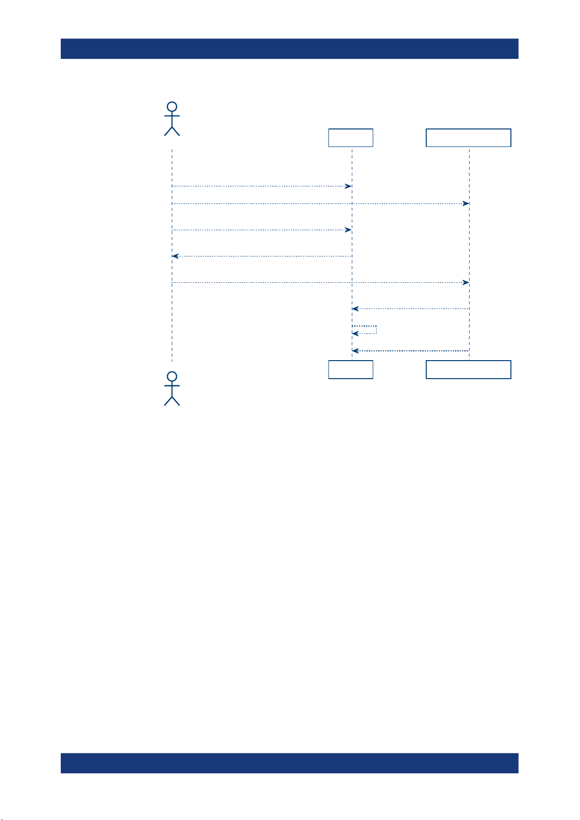
To deploy certificates with tickets
The following figure shows the general workflow if you use self-signed certificates with
tickets.
22Manual 1179.3521.02 ─ 04
Page 23
R&S®CHM
Administrator
Administrator
CHM host
CHM host
CHM Windows agent
CHM Windows agent
Install CHM host software
and generate certificate infrastructure
(./install-chm-server)
Install agent software (MSI)
Generate ticket
(sudo chmpki winagent1.local)
Show ticket
(cb68312a78f6ddf428a3870773d00601e6d9bb0b)
Start script to request certificate with ticket
(chm-certificate-ticket.bat)
Request certificate with ticket
(chm-certificate-ticket.bat)
Create signed certificate
Start sending monitoring results
System administration
Deploying certificates on R&S
CHM agents
1. Log in to the shell of server1.local using ssh.
2. Execute sudo chmpki win1.local.
win1.local must be the FQDN of the windows agent.
A generated ticket is shown.
3. Note down that ticket.
4. Connect to the windows host.
5. Create certificates:
● On Windows, run this batch file:
%programfiles\chm\chm-certificate-ticket.bat
● On CentOS Linux, issue this command:
chm-certificate-ticket
The script prompts you for the server you want to connect to.
6. Enter server1.local and the ticket identifier.
The script creates the necessary certificates and configuration.
If necessary, you can call the script with command-line arguments to execute it
silently:
● On Windows, run the batch file with parameters, all on one line:
chm-certificate-ticket.bat
23Manual 1179.3521.02 ─ 04
Page 24

R&S®CHM
Administrator
Administrator
CHM host
CHM host
CHM Windows agent
CHM Windows agent
Install CHM host software
and generate certificate infrastructure
(./install-chm-server)
Install agent software (MSI)
Start script to request certificate with CSR
(chm-certificate-csr.bat)
Send certificate signing request
Check the open CSRs with "sudo chmca list"
Sign the CSR with "sudo chmca sign"
Start sending monitoring results
System administration
Deploying certificates on R&S
CHM agents
server1.local cb68312a78f6ddf428a3870773d00601e6d9bb0b
● On CentOS Linux, run this command with parameters, all on one line:
chm-certificate-ticket
server1.local cb68312a78f6ddf428a3870773d00601e6d9bb0a
To deploy certificates with signing request
The following figure shows the general workflow if you use self-signed certificates with
certificate signing request (CSR).
1. Execute the configuration script:
%programfiles\chm\chm-certificate-csr.bat
The script prompts you for the server you want to connect to.
2. Type in server1.local.
The script requests the certificate at the R&S CHM host and generates it.
3. Log in to the server via ssh.
4. Execute sudo chmca list.
All signing requests are shown, e.g.
Fingerprint | Timestamp | Signed | Subject
-----------------------------------------------------------------|---------------------|--------|-------403da5b228df384f07f980f45ba50202529cded7c8182abf96740660caa09727 | 2021/09/06 17:02:40 | * | CN = win1.local
71700c28445109416dd7102038962ac3fd421fbb349a6e7303b6033ec1772850 | 2021/09/06 17:20:02 | | CN = win2.local
5. Execute this command to approve the sign request from, e.g win1.local.
24Manual 1179.3521.02 ─ 04
Page 25

R&S®CHM
System administration
sudo chmca sign
403da5b228df384f07f980f45ba50202529cded7c8182abf96740660caa09727
Note: Ensure that the timestamp and CN are correct to ensure that only valid
requests are singed.
The Windows agent can send its monitoring results to the R&S CHM host.
4.2.2 Using CA-signed certificates
As an alternative to self-signed certificates, your company can use private certificate
authorities to issue certificates for your internal servers.
We recommend using the following naming conventions:
●
Certificate of the root CA: ca.crt
●
Certificate of the server: <fqdn>.crt, where fqdn is the fully qualified domain
name (FQDN).
1. Obtain the certificates from your certification authority.
2. Copy the certificates to these locations:
Deploying certificates on R&S
CHM agents
System component Location
R&S CHM host
Windows agent
CentOS Linux agent
/var/lib/icinga2/certs/
%programdata%\icinga2\var\lib\icinga2\certs\
/var/lib/icinga2/certs/
4.2.3 Removing self-signed certificates
If necessary, you can remove all certificates on the R&S CHM host and the agents.
If you remove the certificates, system status monitoring is no longer possible.
► Execute these commands:
● On the R&S CHM host: sudo chm_clean_certificates
● On Windows agents: %programfiles\chm\clean_certificates.bat
● On CentOS Linux agents: sudo chm_clean_certificates
25Manual 1179.3521.02 ─ 04
Page 26

R&S®CHM
System administration
Configuring status monitoring
4.3 Configuring status monitoring
Here, you can find all steps that are necessary to configure R&S CHM for system status monitoring. All data is contained in an editable configuration file. The configuration
file is written in YAML v1.2 notation standard.
YAML is a human readable data serialization language for all programming languages.
YAML is a case-sensitive language. It uses indentation with one or more spaces to represent the structure. Dashes (-) are used to represent the sequences (lists) and colons
(:) are used to represent key-value pairs. The upper part of the configuration file on the
R&S CHM host gives you an impression how this language looks like.
hosts:
- name: host1.de
tags: [chm]
authentication:
monitoring:
- ldap:
server: ldapserv.ourlocal.net
port: 35636
encryption: ldaps
base_dn: ou=ldap_users,dc=ldapserv,dc=ourlocal,dc=net
user_class: user
user_name_attr: sAMAccountName
bind_dn: service_user
bind_pwd_path: ldap/service_user
authorization:
[...]
Related information
●
For more information about YAML, see Chapter 4.3.1, "Introduction to the YAML
syntax", on page 26.
●
For a YAML syntax reference, see the YAML web site at https://yaml.org/
refcard.html.
● Introduction to the YAML syntax............................................................................. 26
● Changing the configuration..................................................................................... 28
● Configuring hosts.................................................................................................... 29
● Configuring R&S CHM web users...........................................................................37
● Managing password identifiers................................................................................41
● Configuring R&S RAMON for monitoring................................................................42
4.3.1 Introduction to the YAML syntax
The YAML syntax contains different kinds of data blocks:
●
A sequence with values that are listed in a specific order. The sequence starts with
a dash and a space - .
26Manual 1179.3521.02 ─ 04
Page 27

R&S®CHM
System administration
Configuring status monitoring
●
A simple mapping between key and value pairs. A key must be unique; the order
does not matter.
A third type is called scalar, which is arbitrary data, such as strings, integers.
Data blocks can be written in block style or flow style.
Example: Sequence data blocks
A list of items in block style.
checks:
- ping:
- os_memory:
- os_process:
A list of items in flow style.
host: [ping , os_memory , os_process]
Example: Mapping data blocks
port: 161
snmp_version: 2
snmp_community: public
checkid: MODEM 1
Example: Dictionary
This data block is a more complex collection of key: value pairs. Each pair can be
nested with numerous options.
hosts:
- domainname: chm-host.domain.net
connections: [icinga2_api]
tags: [chm]
hostgroups: [germany, bavaria]
checks:
- icinga2_cluster:
- dhcp:
- dns:
Table 4-4: Indicator characters - excerpt from the YAML syntax
Collection indicators
: Value indicator.
In threshold configurations, the colon (:) indicates the edges of the interval, see also
Thresholds on page 51
- Nested series entry indicator.
, Separate in-line branch entries.
[ ] Surround in-line series branch.
{ } Surround in-line keyed branch.
27Manual 1179.3521.02 ─ 04
Page 28

R&S®CHM
System administration
Configuring status monitoring
Misc indicators
# Throwaway comment indicator.
Use single quotes (' ') in YAML if your string value includes special characters. For
example, you possibly need single quotes around strings that contain these special
characters:
{, }, [, ], ,, &, :, *, #, ?, |, -, <, >, =, !, %, @, \.
For details, see the YAML specification at https://yaml.org/spec in version v1.2.
4.3.2 Changing the configuration
System administrators with root user account can configure R&S CHM and additional
monitoring hosts and services. All configurations are defined in a single configuration
file, which is the central configuration file for all objects that you want to monitor in the
network.
To access the configuration file
Access authorization: root
► On the R&S CHM host, you can find the configuration file here:
# /etc/opt/rohde-schwarz/chm/chm.yaml
You can edit the file locally. Alternatively, you can transfer the configuration file to
another PC, e.g. using WinSCP with SFTP or FTPS protocols. If finished, transfer it
back to its original location on the R&S CHM host.
To edit the configuration file
Access authorization: root
1. Open the chm.yaml file in an editor.
● On the local R&S CHM host, you can use the vi editor:
vi chm.yaml
● On a remote Windows host, you can use Windows Notepad or a more comfort-
able text editor with YAML syntax highlighting, e.g. Notepad++.
2. In the editor, navigate to the sequence item.
3. Add the key-value pairs.
4. Save the file.
5. If necessary, transfer the file back to its location on the R&S CHM host
(/etc/opt/rohde-schwarz/chm/chm.yaml).
6. Restart these services on the R&S CHM host to take the changes effect:
# sudo systemctl restart chm
# sudo systemctl restart icinga2
28Manual 1179.3521.02 ─ 04
Page 29

R&S®CHM
System administration
Configuring status monitoring
R&S CHM checks the syntax. If the syntax checks failed, edit the configuration file
again and correct all syntax errors.
If the syntax check was successful, the changes are applied. For example, you can
monitor newly configured services on the web GUI.
Check if the services are running:
# sudo systemctl status chm
# sudo systemctl status icinga2
4.3.3 Configuring hosts
Here, you find detailed information on host configuration, including all high-level keys in
the chm.yaml file.
Hosts..............................................................................................................................29
CHM agent connection..................................................................................................... 31
Dummy........................................................................................................................... 31
Export of status information...............................................................................................31
System logging................................................................................................................ 33
Hyperlink to management web interface............................................................................. 35
Host availability................................................................................................................37
Hosts (hosts)
Configure the root element of the chm.yaml file. Specify the configuration and the
checks for the R&S CHM host and all other monitored R&S CHM agents and SNMP
devices.
Parameters:
name Specify the name of the host, i.e. the name of the R&S CHM
host, monitored R&S CHM agents and SNMP devices. A host
configuration always starts with the name key. The first host in
the file always denotes an R&S CHM host.
string
tags Start a host group configuration. A host group comprises several
synchronized hosts. Specify this key for the R&S CHM host.
list of strings
29Manual 1179.3521.02 ─ 04
Page 30

R&S®CHM
System administration
Configuring status monitoring
chm
An R&S CHM host with tags: [chm] starts a monitoring system in which all hosts are synchronized in respect of configuration and monitoring state.
All hosts that are specified beneath, are part of this monitoring
system. The next R&S CHM host with tags: [chm] starts the
next system, and so forth.
In combination with exports, you configure multiple monitoring
systems. These hosts are not synchronized, because the
R&S CHM hosts are separated from each other, e.g. by a security gateway.
logging
exports Configure an R&S CHM host so that it sends status monitoring
authentication Configure LDAP-based user authentication. See
authorization Configure user authorization. See Authorization
webinterface Configure a hyperlink to the management web interface of the
connections Define the check plugin used.
hostgroups List of groups the host belongs to. The groups help identify the
Configure the severity and the facility for event logging on the
R&S CHM host. See System logging on page 33.
information to another R&S CHM host (optional). See
Export of status information on page 31.
Authentication on page 38.
on page 39.
host. See Hyperlink to management web interface
on page 35.
string
[icinga2_win]
Check plugin for Windows agents.
[icinga2_linux]
Check plugin for Linux agents.
host on the web GUI.
string
dummy See Dummy on page 31.
ping See Host availability on page 37.
chm_agent_connectionSee CHM agent connection on page 31.
checks Main key for host-specific checks.
See Chapter 4.4, "Configuring services", on page 47.
For detailed R&S CHM host configuration examples, see Chap-
ter 4.5.1, "R&S CHM host configuration", on page 73 and
Chapter 4.5.2, "Linux host configurations", on page 75
30Manual 1179.3521.02 ─ 04
Page 31
R&S®CHM
System administration
Configuring status monitoring
Example: Single R&S CHM host configuration with some high-level keys.
hosts:
- name: host1.de
tags: [chm]
logging:
severity: info
facility: local0
authentication:
authorization:
webinterface:
connections: [icinga2_linux]
hostgroups: [monitoring, control]
checks: # The checks for this host
CHM agent connection (- chm_agent_connection)
Checks the connection between the R&S CHM host and the R&S CHM service that
runs on an agent. This check enhances reliability of the returned status.
Return status for checked agents:
●
"UP" if the service is running and connection is possible.
●
"DOWN" if the service is not running or connection is not possible.
You can configure this check for agents instead of ping.
Example:
checks:
- chm_agent_connection:
Dummy (- dummy)
Checks nothing but is mandatory if you add a host to the configuration although you do
configure a check for it. The check always shows status "UP" for the host. Use this
check if you cannot use another host check, e.g. if ICMP is blocked in the network.
Example:
- name: host_prepare.net
checks:
- dummy:
Export of status information (exports)
If two R&S CHM systems are separated by a security gateway, you can configure this
key to send status information from one R&S CHM host to the other R&S CHM host.
To do so, you configure the target R&S CHM host and the data format that is used by
R&S CHM for sending status monitoring information.
31Manual 1179.3521.02 ─ 04
Page 32
R&S®CHM
Domain B
Domain A
Monitored items (B)
CHM host
(B)
Monitored items (A)
Displayed items (B)
CHM host
(A)
Security gateway:
[filter data]
[Collect status
information]
[Display status
information]
[Collect status
information]
[Send status
information]
[Receive filtered
status information]
System administration
Configuring status monitoring
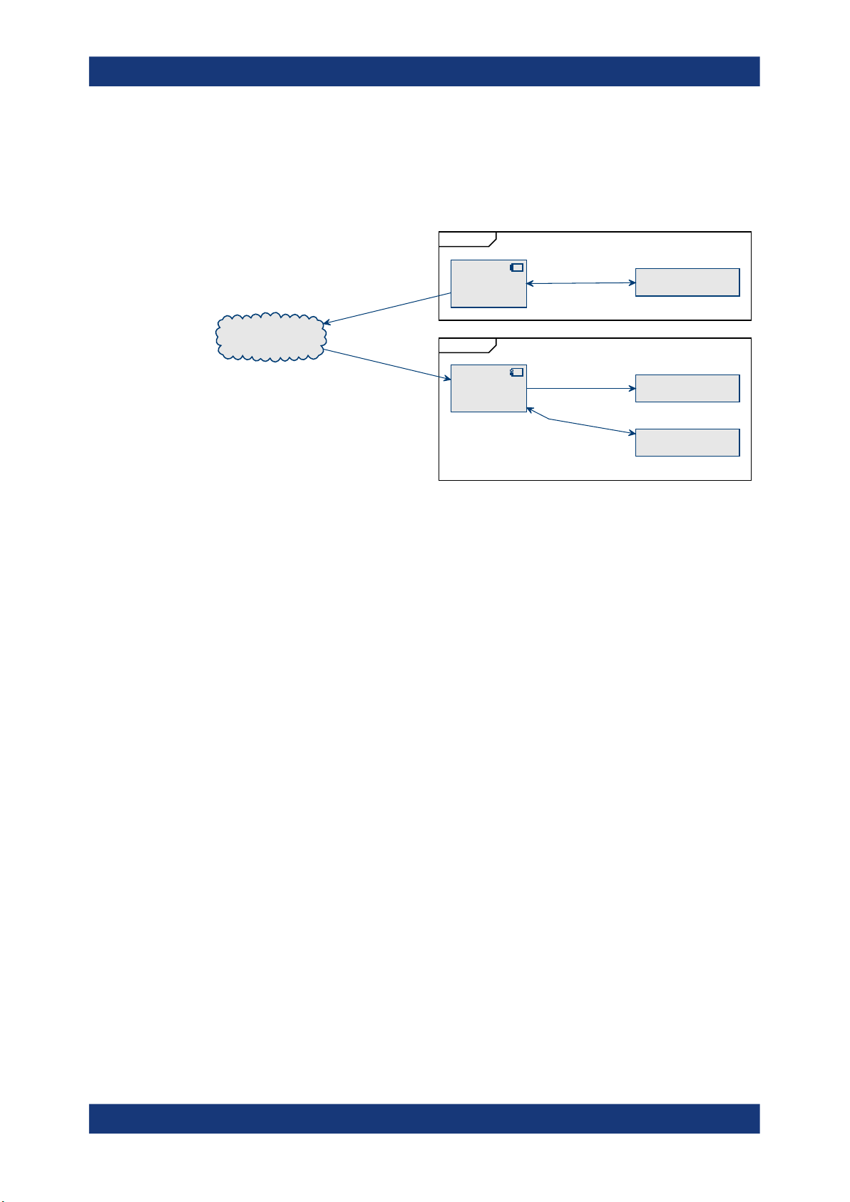
The following figure explains the basic principles. R&S CHM sends status information
from a Domain B to a separated Domain A. On its way, the status information is filtered by a security gateway. R&S CHM host (A) can monitor its own items and display
the monitored items from R&S CHM host (B).
Figure 4-2: Exporting status information form domain B to domain A
Prerequisite
Both R&S CHM hosts need identical chm.yaml files. So, first change the file on one
host. Then, transfer the file to the other host, e.g. using SSH. Example 2 at the end of
this description shows the high-level structure of the chm.yaml file.
Parameters:
xmlhttp Interface used for sending status information. This interface
uses HTTP with content type application/xml on TCP port 5669.
target Name of the R&S CHM host that receives the status information.
proxy If the gateway acts as HTTP proxy, IP address or host name
(optional).
32Manual 1179.3521.02 ─ 04
Page 33

R&S®CHM
System administration
Configuring status monitoring
Example: Configuration with two R&S CHM hosts and some high-level
keys, including exports configuration.
hosts:
# First R&S CHM host
- name: chm-k130-domain-A
tags: [chm]
connections: [local]
logging:
severity: debug
facility: local0
checks:
- load:
- os_process:
name: icinga2
# Second R&S CHM host
- name: chm-k130-domain-B
tags: [chm]
connections: [local]
logging:
severity: debug
facility: local0
exports:
- xmlhttp:
target: chm-k130-domain-A
proxy: 1.2.3.4:5669
checks:
- load:
- os_process:
name: icinga2
System logging (logging)
R&S CHM components send their log events into the Linux journal of the R&S CHM
host. The journal is a binary, ring-buffer like database.
By default, CentOS keeps the journal in volatile memory. You can persist messages to
text files by using the syslog service. It reads the journal and exports to text files by
some filter rules.
Note: Currently, R&S CHM does not provide means to change these export settings. If
you use the syslog service, R&S CHM logging can cause high IO and CPU load and
can degrade flash memory (SSDs). Ensure that only a subset of messages is exported, e.g. warning and higher.
For possible CentOS logging options, see the related man pages.
Logging configuration
You configure the logging level in the chm.yaml file under the hosts key, see Hosts
on page 29.
Viewing logs
33Manual 1179.3521.02 ─ 04
Page 34

R&S®CHM
System administration
Configuring status monitoring
As an administrator, you can view the logs using the # sudo journalctl command.
Log events can originate at different components. For identification of the component,
see Table 4-5.
Parameters:
severity Specifies the severity level, i.e. the importance of the message.
emerg , alert , crit , err , warning , notice , info , debug
For severity details, see Table 4-6.
If you change the severity, e.g. to err, only messages with
severity err or higher are logged (crit, alert, emerg). For
normal operation, we recommend the severity info.
*RST: info
facility Specifies the type of system that is logging the message accord-
ing to RFC 5424. Messages with different facilities can be handled differently.
local0
Locally used facility code. All R&S CHM components send their
logs as facility local0.
Range: local0 to local7
*RST: local0
Example: Logging configuration under the hosts key. The severities
with numerical code "0" to "5" are logged:
logging:
severity: notice
facility: local0
Example: Query of a specific component with # journalctl -t
<Identity> or # journalctl
SYSLOG_IDENTITY=<Identity>:
For example, query the monitoring web UI and the web server
status.
# journalctl -t chm-monitoring-webui -t chm-httpd
Example: Query of successful login, logout and failed login at the web
interface:
# journalctl | grep "User logged in"
# journalctl | grep "User logged out"
# journalctl | grep "User failed to authenticate"
Example: Filter for certain facilities using journalctl
SYSLOG_FACILITY=<facility_code>:
# journalctl SYSLOG_FACILITY=16
For a list of facility codes and their meaning, see RFC5424.
Example: Filter messages by severity with journalctl -p
<severity_or_severity_rage> or journalctl
PRIORITY=<numerical code>:
# journalctl PRIORITY=6
34Manual 1179.3521.02 ─ 04
Page 35

R&S®CHM
System administration
Configuring status monitoring
Example: Message output:
Oct 07 11:25:48 test.local chm-httpd[10476]:
Thu Oct 07 11:25:48.797427 2021] [ssl:info]
pid 121267] [client 172.27.18.70:56854]
AH01964: Connection to child 2 established
(server test.local.net:443)
Table 4-5: Functional components
Component identity Description
icinga2 Monitoring core
chm-monitoring-webui Monitoring web UI
chm-monitoring-webui-audit User login events at the monitoring web UI
chm-httpd Web server status
chm-httpd-req Web server request and responses
Table 4-6: Logging levels (severities) in order of decreasing importance
Parameter value Numerical code Description
emerg 0 Emergency - the system is unusable
alert 1 Alert - an action must be taken immediately
crit 2 Critical conditions
err 3 Error conditions
warning 4 Warning conditions
notice 5 Normal, but significant, condition
info 6 Informational message
debug 7 Debug-level message
Hyperlink to management web interface (webinterface)
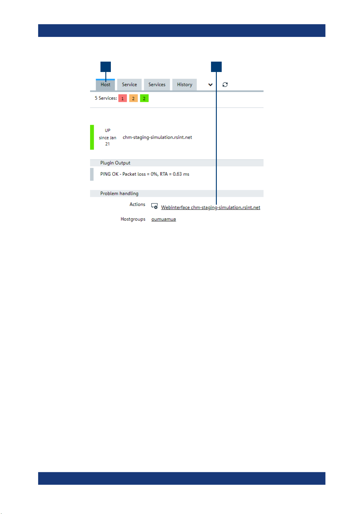
Configure a hyperlink to the management web interface of monitored host. R&S CHM
shows the hyperlink on the web GUI.
35Manual 1179.3521.02 ─ 04
Page 36
R&S®CHM
System administration
Configuring status monitoring
1 2
Figure 4-3: Hyperlink to a web interface
1 = "Hosts" tab
2 = Hyperlink to web interface of the host
Configuration details
Select from the following options:
●
Compose the link automatically from the host name. This mechanism requires that
the host name is specified as fully qualified domain name. R&S CHM system status
monitoring automatically adds https:// in front of the host name to compose the
hyperlink, e.g. https://chm-staging-simulation.rsint.net.
●
Specify a dedicated URL, e.g. https://rohde-schwarz.com. The web GUI
shows this hyperlink.
●
Omit the parameter from the configuration to omit the entry on the web GUI.
HTTP or HTTPS web address of the web interface of the host. If the name of the host
is configured as URI, CHM automatically composes the hyperlink, e.g.
https://chm-staging-simulation.rsint.net.
Example:
Automatically compose hyperlink:
- name: chm-staging-simulation.rsint.net
webinterface:
Resulting hyperlink:
https://chm-staging-simulation.rsint.net
Example: Specific hyperlink:
- name: chm-staging-simulation.rsint.net
webinterface: https://rohde-schwarz.com
36Manual 1179.3521.02 ─ 04
Page 37

R&S®CHM
System administration
Configuring status monitoring
Host availability (- ping)
Checks the availability of a host. To do so, R&S CHM sends ICMPv4 or ICMPv6
requests to the hosts.
This check cannot verify if the R&S CHM service runs on an agent. To check this property, use chm_agent_connection, see CHM agent connection on page 31.
Example:
checks:
- ping:
4.3.4 Configuring R&S CHM web users
Generally, you can select from two options for accessing the R&S CHM web GUI.
Local users
You can log in to the web GUI with one of the predefined local R&S CHM users.
If you do not configure both authentication and authorization, only the local users
admin and operator users are used. Users and permissions are fixed. The admin user
gets all permissions (acknowledge, check, comment, downtime, monitoring). The operator user gets only the monitoring permission.
LDAP users
You can configure an LDAP-based user authentication and authorization method.
R&S CHM then uses this method for restricting the permissions and the users that can
access the web GUI. Using LDAP, you can manage users or user groups centrally and
enhance security.
If you have configured LDAP authentication, the local users are irrelevant. Only LDAP
users can access the web GUI for monitoring the system status.
To control the permissions of the local R&S CHM users
You can use the local users admin and operator without further configuration. However, you can assign specific permissions, e.g. to the operator.
Access authorization: root
1. Under the first hosts list entry, add the authorization key.
2. Configure the permissions for specific roles. For example, configure check
and acknowledge for operators and the full set of permissions to
administrators. For all permissions and configuration details, see
Authorization on page 39.
You have configured the permissions for the local R&S CHM users.
37Manual 1179.3521.02 ─ 04
Page 38

R&S®CHM
System administration
Configuring status monitoring
To configure LDAP user authentication and authorization
LDAP usage also requires a configuration of the R&S CHM users in the central user
management of your company. Ask your local system administrator for support.
If you configure R&S CHM for LDAP authentication, the local users are no longer available on the web GUI.
Access authorization: root
1. Under the first hosts list entry, add the authentication key.
2. Configure user authentication. For the details, see Authentication
on page 38.
3. Add the authorization key on the same indention level as the
authentication key.
4. Configure user authorization. For the details, see Authorization on page 39.
You have configured LDAP user authentication and authorization. You can log in to
the web GUI with the users or user groups that are configured on the LDAP server.
Authentication..................................................................................................................38
Authorization................................................................................................................... 39
Authentication (authentication)
Configure LDAP-based user authentication.
Parameters:
monitoring Configure the authentication method for accessing the web GUI.
ldap Obtain the credentials from a centrally maintained LDAP server.
server Specify the address of the LDAP server, either its fully qualified
domain name or its IP address. You can specify two redundant
LDAP servers to enhance availability of this authentication
method.
<FQDN> , <IP_address>
encryption Configure the encryption method that is used to secure the com-
munication between the LDAP server and the R&S CHM host.
The LDAP server must support your choice.
ldaps
Configure the LDAP over SSL protocol.
starttls
Configure the LDAP over TLS protocol.
base_dn Specify the LDAP distinguished name (DN) of the branch of the
directory where the searches for users start from. The DN
uniquely identifies an object in the active directory.
string
38Manual 1179.3521.02 ─ 04
Page 39

R&S®CHM
System administration
Configuring status monitoring
user_class Specify the LDAP class of user objects.
string
user_name_attr Specify the LDAP attribute that holds the users name that is
used for the login.
string
bind_dn Specify the DN used to bind to the server when searching for
users.
Currently, R&S CHM only supports simple authentication to an
LDAP server. Simple authentication in LDAP is an authentication
method that uses a DN and a password in a bind request for
LDAP authentication to a server.
string
bind_pwd_path The path of the LDAP simple authentication password within the
R&S CHM password store.
See also: Chapter 4.3.5, "Managing password identifiers",
on page 41
string
Example:
Authorization
(authorization)
authentication:
monitoring:
- ldap:
server: [ldapserv.ourlocal.net, ldapserv2.ourlocal.net]
encryption: ldaps
base_dn: ou=Foo_Users,dc=foo,dc=bar,dc=baz
user_class: user
user_name_attr: sAMAccountName
bind_dn: icinga_ldap_user
bind_pwd_path: ldap/icinga_ldap_user
Configure user authorization. For the rules that apply for various configuration combinations, especially with LDAP authentication, see Chapter 4.3.4, "Configuring
R&S CHM web users", on page 37.
Parameters:
monitoring Configure the authorization method for web GUI users.
roles Specify and configure the user roles that are available. You can
choose the names freely, e.g. administrators and
operators. The specified roles are generated on the
R&S CHM host.
string
permissions List of permissions that is assigned to the role (optional).
acknowledge
Acknowledge hosts or service problems by selecting the
"Acknowledge" button on the web GUI.
39Manual 1179.3521.02 ─ 04
Page 40

R&S®CHM
System administration
Configuring status monitoring
check
Start a check immediately by selecting the
"Check now" button
on the web GUI.
comment
Leave a comment for a host or service by selecting the
"Com-
ment" button on the web GUI.
downtime
Schedule a downtime by selecting the "Downtime" button on
the web GUI. Host or service problems do not show up for the
dedicated host or service during the downtime.
users List of users to which the role is applied, e.g. admin, operator,
john (optional).
Either specify users or groups.
<LDAP_user_name>
If you have configured LDAP authentication, only specify LDAP
user names.
admin
Name of the local administrator. Default password is
operator
Name of the local operator.
groups List of LDAP user groups to which R&S CHM applies the role ,
e.g. company_chm_admins (optional).
This key is only relevant, if you have configured LDAP authentication.
string
Name of the LDAP group.
Example: Example with LDAP users
authorization:
monitoring:
roles:
operators:
permissions:
- acknowledge
- comment
- check
users:
- chm_operator
- chm_monitor
40Manual 1179.3521.02 ─ 04
Page 41

R&S®CHM
System administration
Configuring status monitoring
Example: Example with LDAP groups
authorization:
monitoring:
roles:
administrators:
permissions:
- acknowledge
- comment
- downtime
groups:
- company_chm_admins
4.3.5 Managing password identifiers
All passwords for communication between R&S CHM and an LDAP server or
R&S CHM and the monitored services are encrypted using GPG. To ease password
handling, R&S CHM provides a password manager.
The password manager lets you safely specify necessary password identifiers for communication of R&S CHM via the following interfaces:
●
LDAP simple authentication password
●
SNMP
●
Proprietary interfaces, e.g. VMware
To list all password identifiers
Access authorization: root
1. Log in to the R&S CHM host.
2. Enter the following command:
# chmpass ls
The currently defined password identifiers are listed. For an example output, see
the following example.
Example: List configured password identifiers
$ chmpass ls
Password Store
├── tiger
├── bumblebee
└── ant
To add a password identifier
Access authorization: root
1. Log in to the R&S CHM host.
2. Type the following command:
# chmpass insert <password_identifier>.
41Manual 1179.3521.02 ─ 04
Page 42

R&S®CHM
System administration
Configuring status monitoring
Example: # chmpass insert tiger
3. Enter the password identifier.
4. Repeat the password identifier.
You successfully added the password identifier.
To remove a password identifier
Access authorization: root
1. Log in to the R&S CHM host.
2. Enter the following command:
# chmpass rm <password_identifier>
3. Confirm deletion.
You successfully removed the specified password identifier.
Example: Delete a password identifier
The name of the identifier is "tiger".
$ chmpass rm tiger
Are you sure you would like to delete tiger? [y/N] y
removed ‘/var/opt/chm/password-store//tiger.gpg’
To set a password identifier in the configuration file
Access authorization: root
1. Access the chm.yaml file.
See also: "To access the configuration file" on page 28
2. Under the check: key for the resource, add the key-value pair:
<identifier>: <password_identifier>
Examples
● For snmpv3: snmp_secname: tiger
● For vmware: user: lion
R&S CHM can access the checked resources via the set password identifier.
4.3.6 Configuring R&S RAMON for monitoring
This monitoring method uses a gRPC-based R&S CHM service called chmrd. It replaces the deprecated Windows SNMP service.
42Manual 1179.3521.02 ─ 04
Page 43

R&S®CHM
System administration
Configuring status monitoring
Monitored host R&S CHM host
Monitored application
(R&S RAMON)
Publish health
check via grpc:
port 18006
CHM monitoring
chmrd service
TLS encrypted:
port 18005
TLS encrypted:
port 18005
Network
Figure 4-4: Monitoring of applications, e.g. R&S RAMON
The following description explains the monitoring steps visualized in the previous figure.
Monitored application and R&S CHM
Applications "publish" monitoring data to chmrd. R&S CHM fetches the monitoring
data from chmrd.
The chmrd service
The service chmrd gathers monitoring data sent by applications and makes it available
to R&S CHM instances. Currently, it has to be installed on the same Windows host that
also runs the monitored application. It is necessary that you install the chmrd.msi on
the agent that runs R&S RAMON, see "To install Windows agents" on page 20.
Interface definition
The service provides a gRPC interface that can be used to both send and query monitoring data. The interface is defined in a protobuf file. This file describes the services
provided by chmrd and the data model that is used for communication and even how
this data is serialized on the wire. The file thus takes the role of a serialization document.
Security aspects
The chmrd service uses two separate TCP ports:
●
For communication with clients on the same host: local port, default port number
18006
On the local port, the service only listens for connections from localhost. There is
no encryption or authentication or authorization when using the local port. Its main
use case is for communication between chmrd and the monitored application.
●
For clients on remote hosts: remote port, default port number 18005.
43Manual 1179.3521.02 ─ 04
Page 44
R&S®CHM
4.3.6.1 Configuring the chmrd service
System administration
Configuring status monitoring
When communicating over the remote port, chmrd enforces TLS encryption and
client authentication using X.509 certificates to secure network communication.
There is no authorization mechanism in place yet which means an authenticated
client is allowed to both send and query monitoring data without any restrictions.
The only officially supported way of configuring chmrd is to pass command-line arguments to the service.
Typically, you can use the default chmrd configuration. However, if you need to change
the configuration, continue as described in the following procedure.
To configure the chmrd service
This procedure assumes that the chmrd software is already installed.
1. Open the installation directory:
C:\Program Files\Rohde-Schwarz\chmrd\
2. Open a command prompt window in the installation directory.
3. Run the following command:
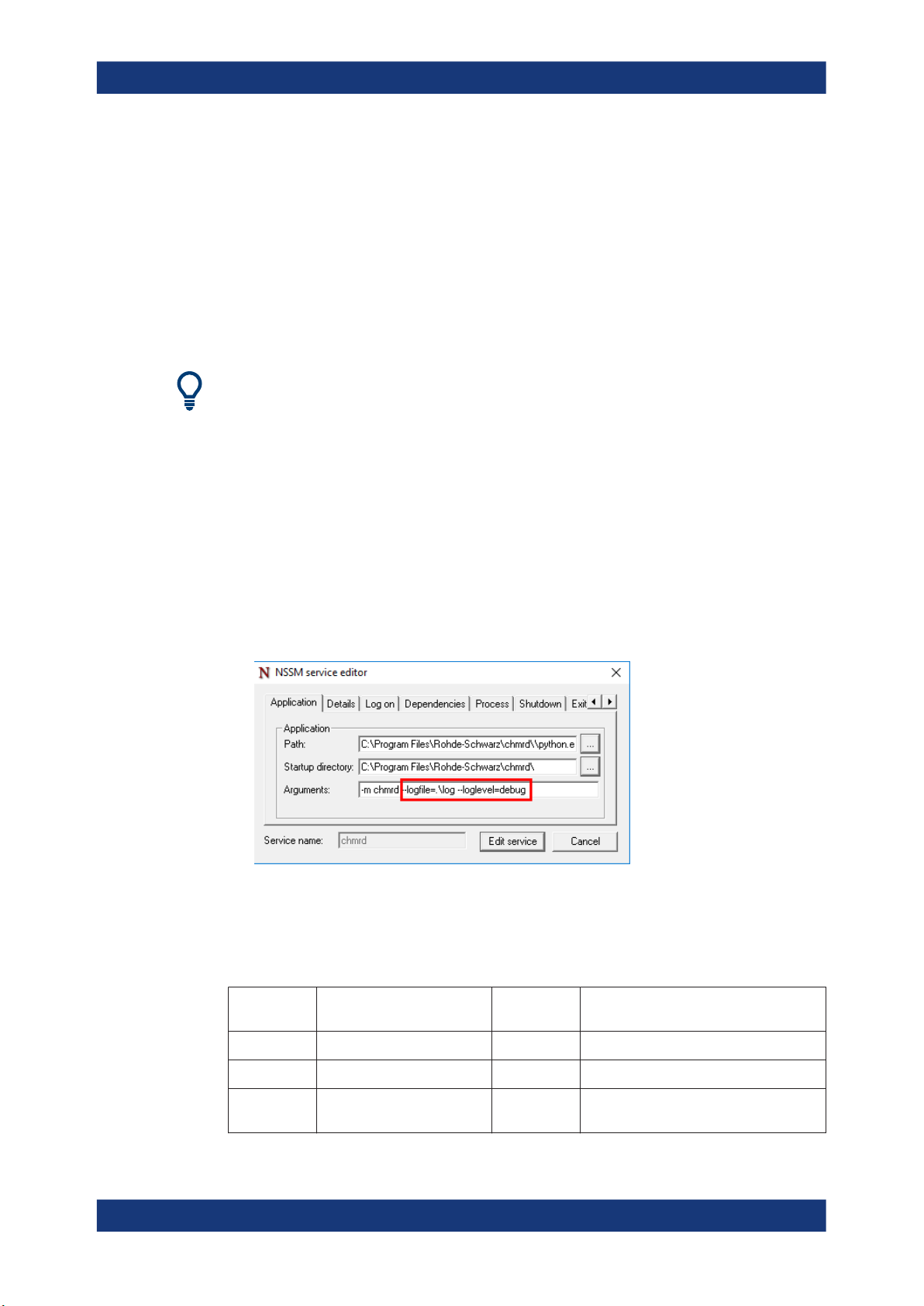
.\nssm.exe edit chmrd
The "NSSM service" editor opens.
4. Configure the desired arguments as listed in Table 4-7.
Note: Always keep the "-m chmrd" argument. This information tells the python
interpreter which module to use to start the service.
Table 4-7: Command-line arguments for configuring the chmrd service
Argument
(short)
Argument (long) Default
value
Description
"-a" "--address" "0.0.0.0" IP address the server runs on
"-p" "--port" "18005" Port for connections from remote hosts
" -P" " --local-port" "18006" Port that clients on localhost can use with-
out needing to authenticate themselves
44Manual 1179.3521.02 ─ 04
Page 45

R&S®CHM
System administration
Configuring status monitoring
Argument
(short)
"-d" "--cert-dir"
" -C" "--server-cert"
" -R" "--server-root-cert"
" -K" "--server-priv-key"
" -c" "--client-root-cert"
Argument (long) Default
value
" --insecure"
"--loglevel" "info" One of "debug", "info", "warning", "error",
"--logfile"
" -- logfilemode" "w" "a" or "w"
Description
Directory with certificates and keys
Server certificate path
Server root certificate path
Server-private key path
Client root certificate path
If set, disable encrypted message transport and server/client authentication (without a value)
"critical"
Logfile path
"a" for appending to log file.
"w" for truncating log file and starting a
new one when the service is restarted
Example:
The following arguments set specific ports and how the log file is treated.
"-m chmrd -p=18007 -P=18008 --logfilemode=a"
About certificates and keys
All certificates and keys used for chmrd have to be PEM encoded.
To achieve encrypted and authenticated network communication, chmrd needs the following:
●
A server certificate chain
A certificate chain is a list of certificates where the issuer of each one of them
matches the subject of the following. Also each certificate - except for the last - is
signed with the secret key corresponding to the next certificate. The last certificate
in the chain is self-signed, which makes it a root certificate.
Usually, this chain consists of a certificate issued for the host on which the service
is running. This certificate is followed by some root CA's certificate that was used to
issue the certificate of the host. You can specify these two parts of the certificate
chain by using the "--server-cert" and the "--server-root-cert" arguments, including
the path to the corresponding files.
For the uncommon use case that the chain consists of more than two certificates,
you can split up the certificates to the two files specified by "--server-cert" and "-server-root-cert". Make sure that the resulting chain fulfills the criteria for a certificate chain described above.
●
A server-private key
This key is the private key corresponding to the certificate on the server, i.e. the
monitored host used for encrypting network communication. The file containing the
key can be specified by using the "--server-priv-key" argument.
45Manual 1179.3521.02 ─ 04
Page 46

R&S®CHM
System administration
Configuring status monitoring
●
A client root certificate
chmrd expects remote clients to provide a certificate chain to authenticate themselves. You can specify a file containing one or more root certificates for these
chains by using the "--client-root-cert" argument.
Default paths for certificates and keys
There are different possible combinations of how to use command-line arguments in
chmrd. The following tables list the defaults that are used in the different cases A, B
and C.
A) If no command-line arguments are specified, the defaults use the fully qualified
domain name (FQDN) of the host, see the following table.
Table 4-8: No command-line arguments are specified
Argument (long) Default value
"--server-cert"
"--server-priv-key"
"--server-root-cert"
"--client-root-cert"
C:\ProgramData\icinga2\var\lib\icinga2\certs\<FQDN>.crt
C:\ProgramData\icinga2\var\lib\icinga2\certs\<FQDN>.key
C:\ProgramData\icinga2\var\lib\icinga2\certs\ca.crt
C:\ProgramData\icinga2\var\lib\icinga2\certs\ca.crt
The default file locations here correspond to the certificate settings you usually already
made for the R&S CHM Windows agent, see Chapter 4.2, "Deploying certificates on
R&S CHM agents", on page 21. Thus, no extra configuration is necessary for the
chmrd service. Also, the chmrd service expects that both server and clients to use
same root certificate by default.
B) If you specify "--cert-dir", you can set a custom location for all certificates and key,
see the following table.
Table 4-9: Only --cert-dir is specified
Argument (long) Default value
"--server-cert"
"--server-priv-key"
"--server-root-cert"
"--client-root-cert"
<CERT_DIR>\<FQDN>.crt
<CERT_DIR>\<FQDN>.key
<CERT_DIR>\ca.crt
<CERT_DIR>\ca.crt
C) If one or all "--server-cert", "--server-root-cert", "--server-priv-key", "--client-root-cert"
are specified, you can always specify a customized, absolute path to certificates and
key.
For information about configuration of the check in the chm.yaml file, see
gRPC-based R&S RAMON monitoring on page 66.
46Manual 1179.3521.02 ─ 04
Page 47

R&S®CHM
System administration
Configuring services
4.4 Configuring services
R&S CHM can monitor a specific set of services. The following description provides an
overview of the hardware and software services you can monitor. Also, you find necessary information for configuration of new services.
Table 4-10: Syntax conventions
Identifier Description
*RST Default value
● Frequent keys......................................................................................................... 47
● Hardware services.................................................................................................. 51
● Software services....................................................................................................63
4.4.1 Frequent keys
Here, you can find the description of frequent keys (parameters) that you can use in
the check sections of configured hosts. For example, you need SNMP in all checks
that are based on this protocol.
Checkgroups................................................................................................................... 47
Display name...................................................................................................................47
SNMPv2 protocol............................................................................................................. 47
SNMPv3 protocol............................................................................................................. 48
Thresholds...................................................................................................................... 51
Checkgroups (checkgroups)
Assigns a check to one or more specific groups that you can configure and display on
the web GUI.
Example:
checkgroups: [Cluster, Buster]
Example: If the check group contains a colon (:), enclose the whole check
group string in quotation marks.
checkgroups: ["Resources :- Disk space"]
Display name (displayname)
Display a user-friendly name on the GUI.
Example:
displayname: My special service name
SNMPv2 protocol (snmp_<property>)
Specify the properties of the SNMPv2 connection for unencrypted communication
between R&S CHM and the device. The following parameters also apply to the
SNMPv1 protocol.
47Manual 1179.3521.02 ─ 04
Page 48

R&S®CHM
System administration
Configuring services
For these common SNMP protocol parameters, see also SNMPv3 protocol
on page 48.
port
●
snmp_retries
●
snmp_timeout
●
Parameters:
snmp_version SNMP protocol version, here version 1 or 2. See also
SNMPv3 protocol on page 48.
numeric
Range: 1 to 2
*RST: 2
snmp_community SNMP community string for SNMPv1/v2 transactions. The com-
munity is a type of shared password between the SNMP management station and the device, which is used to authenticate
the SNMP management station.
string
*RST: public
Example:
port:161
snmp_version: 2
snmp_community: public
SNMPv3 protocol (port, snmp_<property>)
Specify the properties of the SNMPv3 connection for encrypted communication
between R&S CHM and the device.
See also: SNMPv2 protocol on page 47
Parameters:
port Communication port at the device, the SNMP agent (optional).
numeric
*RST: 161
snmp_version SNMP protocol version.
3
*RST: 2
snmp_secname Identifier (security name) used for authenticated SNMPv3 mes-
sages.
See also: Chapter 4.3.5, "Managing password identifiers",
on page 41
string
48Manual 1179.3521.02 ─ 04
Page 49

R&S®CHM
System administration
Configuring services
snmp_authproto Authentication protocol used for authenticated SNMPv3 mes-
sages. If your operating system is hardened with FIPS mode,
you cannot use MD5.
MD5 , SHA , SHA-224 , SHA-256 , SHA-384, SHA-512 , None
*RST: MD5
snmp_authpass Password used for authenticated SNMPv3 messages (optional).
If not specified, R&S CHM looks up the password in the password store using the snmp_secname value as the identifier.
string
Option 1: Clear text password as used in the example at the
end of this key description.
Option 2: VAULT:<path_to_vault> as used in the example at the
end of this key description (recommended).
Option 3: If not specified, R&S CHM looks up the password in
the password store using the snmp_secname value as the identifier as used in the example at the end of this key description.
snmp_privproto
snmp_privpass Password used for encrypted SNMPv3 messages (optional).
snmp_context Context name used for SNMPv3 messages, e.g.
snmp_seclevel Security level used for SNMPv3 messages.
Privacy protocol used for encrypted SNMPv3 messages.
DES , 3DES, AES-128, AES-192 , AES-256, None
*RST: DES
string
Option 1: Clear text password as used in the example at the
end of this key description.
Option 2: VAULT:<path_to_vault> as used in the example at the
end of this key description (recommended).
Option 3: If not specified, R&S CHM looks up the password in
the password store using the snmp_secname value as the identifier as used in the example at the end of this key description.
spectracom_time
string
*RST: empty string ""
noAuthNoPriv , authNoPriv , authPriv
noAuthNoPriv authenticates with a username, i.e. no authentication and no encryption.
AuthNoPriv provides HMAC MD5 or SHA algorithms for
authentication but no encryption.
AuthPriv provides HMAC MD5 or SHA algorithms for authentication and DES 56-bit encryption.
snmp_retries Number of retries to be used in the requests (optional).
numeric
*RST: 5
49Manual 1179.3521.02 ─ 04
Page 50

R&S®CHM
System administration
Configuring services
snmp_timeout Timeout between retries (optional). Floating point numbers can
be used to specify fractions of seconds, e.g. 1.25.
numeric
*RST: 1
Default unit: s
Example: Option 1: Use the password store for a Spectracom Secure-
Sync timeserver and write the passwords in clear text to the
chm.yaml configuration file:
- spectracom_timeserver:
checkgroups: [water, earth, fire, air]
port: 1234
snmp_version: 3
snmp_secname: rsadmin
snmp_authproto: SHA
snmp_authpass: privatusprivatusprivatusprivatus
# clear text password
snmp_privproto: AES-256
snmp_privpass: privatusprivatusprivatusprivatus
# clear text password
snmp_context: spectracom_time
Example:
Example:
Option 2: Use the password store with different passwords for
snmp_authpass and snmp_privpass:
- nport
checkgroups: [water, earth, fire, air]
snmp_version: 3
snmp_context: nport
snmp_secname: mydeviceaccount # the snmp user
snmp_authpass: VAULT:snmp_passwords/nport/device1
# The path to the password in the passwordstore
snmp_privproto: AES-256
snmp_privpass: VAULT:snmp_passwords/nport/device1/privpass
snmp_authproto: SHA
...
Option 3 (deprecated): Use the password store with identical
passwords:
- nport:
checkgroups: [water, earth, fire, air]
snmp_version: 3
snmp_context: nport
snmp_secname: mydeviceaccount
# lookup of passwords in password store
snmp_authproto: SHA
snmp_privproto: AES-256
50Manual 1179.3521.02 ─ 04
Page 51

R&S®CHM
System administration
Configuring services
Thresholds (thresholds)
Specify thresholds for alert levels. Use thresholds together with suitable checks as
mentioned in the description of the checks.
Thresholds are implemented according to the Monitoring Plugins Development Guide-
lines. The Table 4-11 is adopted from this guide.
Parameters:
warning Threshold for the warning alert level.
critical Threshold for the critical alert level.
Example:
Generalized format of ranges:
[@]start:end
Table 4-11: Example ranges
Range definition Generate an alert if x...
10 < 0 or > 10 (outside the range of {0 .. 10})
10: < 10, (outside {10 .. ∞})
~:10 > 10, (outside the range of {-∞ .. 10})
10:20 < 10 or > 20 (outside the range of {10 .. 20})
@10:20 ≥ 10 and ≤ 20 (inside the range of {10 .. 20})
4.4.2 Hardware services
thresholds:
warning: :0 # E.g. alert if 1 or more exceed. occurred
critical: :0 # E.g. alert if 1 or more exceed. occurred
thresholds:
warning: 20: # E.g. alert if check cond. falls below 20
critical: 10: # E.g. alert if check cond. falls below 10
Here, you can find all services that you configure for monitoring of hardware components.
Cisco hardware................................................................................................................52
CPU load........................................................................................................................ 52
Dell iDRAC hardware....................................................................................................... 54
Disk space...................................................................................................................... 55
HP iLO hardware............................................................................................................. 56
Moxa NPort 6000 series server..........................................................................................57
Network interface............................................................................................................. 58
Memory usage.................................................................................................................59
Spectracom SecureSync timeserver...................................................................................60
Uninterruptible power supply - RFC1628-compatible............................................................61
VMware ESXi/vcenter server inventory...............................................................................62
51Manual 1179.3521.02 ─ 04
Page 52

R&S®CHM
System administration
Configuring services
Cisco hardware (- cisco_hardware)
Monitor the hardware status of a Cisco switch via SNMP. The check monitors fans,
temperature, powersupplies and modules.
Supported devices
All devices, including Cisco Catalyst 9300, that support the following MIBs:
●
CISCO-ENVMON-MIB
●
CISCO-STACKWISE-MIB
●
CISCO-ENTITY-FRU-CONTROL-MIB
Related parameters
●
SNMPv3 protocol, SNMPv2 protocol
Parameters:
device_name Name of the device. This name is shown in the status summary
(optional).
string
return_status Return status for failures (optional).
CRITICAL , WARNING
fans Number of built-in fans (optional).
numeric
*RST: 2
powersupplies Number of built-in power supplies (optional).
numeric
*RST: 2
Example:
CPU load
(- load)
- cisco_hardware:
device_name: CISCO 9300 Center Switch
fans: 3
returnstatus: WARNING
Monitor CPU load on Windows and Linux hosts.
Parameters:
thresholds Check-specific alert levels. For more information about the
threshold syntax, see Thresholds on page 51. The following
values only apply to the current load on Windows.
For Linux, see load<minutes>.
*RST: warning: 90, critical: 99
Default unit: %
52Manual 1179.3521.02 ─ 04
Page 53

R&S®CHM
System administration
Configuring services
load<minutes> On Linux, check load averages in the last 1 min, 5 min and 15
min (fixed). The threshold defines the utilization ratio of all processor cores.
The Linux load averages depend on the number of processor
cores. For a single-core processor, a load of 1.0 means that the
processor is exactly at capacity. Smaller values indicate that
there is still capacity available. Higher values indicate problems,
i.e. the system is slowing down or hanging.
On a multicore system, ensure that the load does not exceed the
number of cores available. It does not matter how the cores are
spread out over CPUs. Two quad-cores match four dual-cores
match eight single-cores, i.e. in sum consider eight cores
when configuring the alert levels.
warning, critical
Increment:
0.01
Default unit: numeric
For alert level defaults, see Table 4-12.
Example:
On Windows
-load:
thresholds:
warning: 90
critical: 99
Example: On Linux
- load:
thresholds:
load1:
warning: 5.0
critical: 10.0
load5:
warning: 4.0
critical: 6.0
load15:
warning: 3.0
critical: 4.0
Table 4-12: Load threshold defaults on Linux
Load averaging Alert level and threshold defaults
load1 warning: 5.0
critical: 10.0
load5 warning: 4.0
critical: 6.0
load15 warning: 3.0
critical: 4.0
53Manual 1179.3521.02 ─ 04
Page 54

R&S®CHM
System administration
Configuring services
Dell iDRAC hardware (- idrac)
Monitor the hardware status of a server with a Dell iDRAC interface via SNMP.
Checked values
●
Global system status
●
Global lcd status
●
System power
●
Global storage status
●
Power unit redundancy
●
Power unit status
●
Chassis intrusion sensor status
●
Cooling unit status
●
Status of all drives
●
Predictive status of all drives
●
All temperatures
If a component does not exist or if a sensor in the server version does not exist, set
this check manually to true. For example, if there are no hard disks (diskless server),
set key no_disks to true.
Related parameters
●
SNMPv3 protocol, SNMPv2 protocol
Parameters:
no_storage Do not check global storage condition (optional).
true
no_system Do not check global system status (optional).
true
no_power Do not check global power status (optional).
true
no_temperature Do not check overall thermal environment condition (optional).
true
no_disks Do not check the disks (optional).
true
no_power_unit Do not check the power unit (optional).
true
no_intrusion Do not check the intrusion sensor (optional).
true
no_cooling Do not check the cooling unit (optional).
true
54Manual 1179.3521.02 ─ 04
Page 55

R&S®CHM
System administration
Configuring services
no_redundancy Do not check the power unit redundancy (optional).
true
no_predictive Do not check the predictive status of the disks (optional).
true
no_lcd Do not check the LCD status (optional).
true
Example:
- idrac:
no_power_redundancy: true
Disk space (- os_disk)
Monitor available disk space.
Parameters:
include List of drives (on Windows) or volumes (on Linux) that are moni-
tored (optional). If not set, R&S CHM monitors all disks or volumes.
string
*RST: none
thresholds Alert levels for available disk space (optional).
For more information about the thresholds syntax, see
Thresholds on page 51.
warning , critical
On Windows: used disk space.
On Linux: free disk space.
Range: 0 to 100
*RST: none (Windows) , 10 (Linux warning) , 20 (Linux
critical)
Default unit: %
Example: For a Windows host
- os_disk:
include: ['C', 'F']
thresholds:
warning: 80
critical: 90
Example: For a Linux host
- os_disk:
include: ['/', '/boot']
thresholds:
warning: 10:
critical: 5:
55Manual 1179.3521.02 ─ 04
Page 56

R&S®CHM
System administration
Configuring services
HP iLO hardware (- ilo)
Monitor the hardware status of a server with Hewlett-Packard iLO interface via SNMP.
Checked values
●
Global storage status
●
Global memory status
●
Global system status
●
Global power supply status
●
Global power state (ON/OFF)
●
Global thermal system
●
Global temperature sensors
●
Global fan status
●
Disk controllers
●
Power supply redundancy
●
Fans
●
Disk drives status
●
Disk drives smart values
●
Disk temperatures
If a component or a sensor does not exist, set this check manually to true.
Related parameters
●
SNMPv3 protocol, SNMPv2 protocol
Parameters:
drives Number of physical drives.
numeric
ps Number of connected power supplies.
numeric
fan Number of fans.
numeric
[no_storage] Do not check global storage condition (optional).
true
[no_system] Do not check global system state (optional).
true
no_powersupply Do not check global power supply condition (optional).
true
no_powerstate Do not check power state (optional).
true
no_temp Do not check overall thermal environment condition (optional).
true
56Manual 1179.3521.02 ─ 04
Page 57

R&S®CHM
System administration
Configuring services
no_temp_sensors Do not check temperature sensor condition (optional).
true
no_temp_drives Do not check temperature sensor of the hard drives (optional).
true
no_fan Do not check global fan condition (optional).
true
no_memory Do not check memory condition (optional).
true
no_controller Do not check controller condition (optional).
true
no_logical_drives Do not check the logical drives (optional).
true
no_power_redund Do not check power supply redundancy (optional).
true
Example:
- ilo:
drives: 2
ps: 1
fan: 3
no_power_redund: true
Moxa NPort 6000 series server (- nport)
Monitor a Moxa NPort 6000 series serial server via SNMP.
Supported MIBs
●
RFC1213-MIB
●
MOXA-NP6000-MIB
Related parameters
●
SNMPv3 protocol, SNMPv2 protocol
Parameters:
serial_port Monitored serial port.
numeric
name Port name.
string
errormessage Additional error message that indicates the status failure.
string
returnstatus Return status for failures.
"CRITICAL" , "WARNING"
57Manual 1179.3521.02 ─ 04
Page 58

R&S®CHM
System administration
Configuring services
dsr , cts , dtr Checks for the serial DSR, CTS or DTR flow control if the OK
status is HIGH or LOW:
HIGH , LOW
Example:
-nport:
serial_port: 2
dtr: LOW
dsr: HIGH
cts: LOW
errormessage: "GENERATOR FAILED"
name: "GENERATOR INPUT"
returnstatus: "WARNING"
-nport:
serial_port: 3
dtr: LOW
errormessage: "AIRCONDITION FAILED"
Network interface (- nw_interface)
Monitor the status of the network interface of devices that implement the RFC1213MIB via SNMP.
Checked values
●
Speed of the network interface
●
Operational status
●
Administrative status
●
Port security MAC based
●
Port security 702.1x based
Related parameters
●
SNMPv3 protocol, SNMPv2 protocol
Specify the interface properties and select one or more of the following checks and
their defined "ok" status.
Parameters:
interface Set the network interface to be monitored.
numeric
*RST: 1
name Set the name for the interface (optional).
string
errormessage Specify an additional error message that is shown if the status
fails (optional).
string
returnstatus Define the return value if the check fails (optional).
WARNING , CRITICAL
58Manual 1179.3521.02 ─ 04
Page 59

R&S®CHM
System administration
Configuring services
speed Check the speed of the network interface, e.g. 100, 1000 MBit/s
(optional).
numeric
*RST: 1000
Default unit: MBit/s
op_status Check the operational status of the network interface (optional).
UP , DOWN , TESTING , UNKNOWN , DORMANT , NOTPRESENT , LOWERLAYERDOWN
admin_status Check the administration status of the network interface
(optional).
UP , DOWN , TESTING
port_sec_mac Check the MAC-based port security status of a device that is
compatible with CISCO-PORT-SECURITY-MIB (optional).
port_sec_802 Check the 802.1-based port security status of a device that is
compatible with CISCO-PAE-MIB (optional).
port_sec_ieee802 Check that the PAE auth controlled port status of an interface is
"AUTHORIZED" of a device that is compatible with the
IEEE8021-PAE-MIB (optional).
Example:
- nw_interface:
interface: 2
speed: 1000
op_status: UP
admin_status: UP
errormessage: "Failure on network interface for server"
name: "server interface"
returnstatus: "WARNING"
port_sec_mac:
- nw_interface:
interface: 3
speed: 100
port_sec_802:
- nw_interface:
interface: 4
port_sec_ieee802:
Memory usage (- os_memory)
Monitor RAM usage. This check lets you detect when your operating system is about
to swap.
Related parameters
●
Thresholds
59Manual 1179.3521.02 ─ 04
Page 60

R&S®CHM
System administration
Configuring services
Example:
- os_memory:
thresholds:
warning: '10:'
critical: '5:'
Spectracom SecureSync timeserver (- spectracom_timeserver)
Monitor a Spectracom SecureSync timeserver via SNMP.
Checked values
●
Status of AC and DC power supply
●
Major and minor alarms
●
GPS reference antenna status
●
GPS reference time validity
●
System synchronization status
●
System holdover status
●
Amount of satellites
Supported MIBs
●
SPECTRACOM-SECURESYNC-MIB
Tested devices
●
Spectracom SecureSync GT4030
Related parameters
●
SNMPv3 protocol, SNMPv2 protocol
Parameters:
name The name for the device that is shown in the check results.
string
*RST: Spectracom SecureSync
no_acpower Do not check the AC power status (optional).
no_dcpower Do not check the DC power status (optional). This key requires
that you specify no_dcpower: true in the configuration file.
true
no_minor_alarm Do not check for minor system alarms (optional).
no_major_alarm Do not check for major system alarms (optional).
no_ref_time_validity Do not check the GPS ref time validity (optional).
no_sync_state Do not check the system sync status.
no_holdover_state Do not check the system holdover status (optional).
no_ref_antenna_state Do not check the GPS ref antenna status (optional).
no_tracked_satellites Do not check the number of tracked satellites (optional).
60Manual 1179.3521.02 ─ 04
Page 61

R&S®CHM
System administration
Configuring services
thresholds Specify check-specific alert levels (optional). For more informa-
tion about the threshold syntax, see Thresholds on page 51.
tracked_satellites Define the thresholds for the number of tracked satellites
(optional).
boolean
*RST: warning: 5, critical: 3
Example:
- spectracom_timeserver:
name: Spectracom GT4030
no_dcpower:
thresholds:
tracked_sattelites:
- warning: 5:
- critical: 3:
Uninterruptible power supply - RFC1628-compatible (- ups)
Monitor a UPS that is compatible to RFC1628 via SNMP.
Related parameters
●
SNMPv3 protocol, SNMPv2 protocol
●
Thresholds
Select one of the following checks. Each check returns a single metric.
Parameters:
alarms Check the present number of active alarm conditions.
In combination with thresholds, R&S CHM generates an alert.
secondsonbattery Check if the unit is running on battery power? If not, the UPS
returns zero.
If the unit is not running on battery power the following is
checked, whichever is less:
The elapsed time since the UPS last switched to battery power.
– or –
The time since the network management subsystem was last
restarted.
In combination with thresholds, R&S CHM generates an alert.
Default unit: s
minutesremaining Check estimated time to battery charge depletion under the
present load conditions in the following cases:
The utility power is off and remains off.
– or –
The utility power is going to be lost and remains off.
In combination with thresholds, R&S CHM generates an alert.
Default unit: min
thresholds Specify check-specific alert levels. For more information about
the threshold syntax, see Thresholds on page 51.
61Manual 1179.3521.02 ─ 04
Page 62

R&S®CHM
System administration
Configuring services
Example:
- ups:
alarms:
thresholds:
warning: '0:'
critical: '0:'
- ups:
secondsonbattery:
thresholds:
warning: '0:'
critical: '0:'
- ups:
minutesremaining:
thresholds:
warning: '~:20'
critical: '~:10'
VMware ESXi/vcenter server inventory (- vmware)
Monitor a VMware ESXi/vcenter server, e.g. datastores. You can specify up to four
checks for a host.
Available checks
●
Alarms
●
Datastore usage
●
CPU usage
●
Memory usage
Related parameters
●
Thresholds
Parameters:
user The user name that is used to log in at the server.
string
insecure Check the server certificate (optional).
false , true
Server certificate is checked ('false') or not checked ('true').
*RST: false
type The entity type of the monitored object: alarm, datastore,
hostsystem.
alarm Currently not acknowledged alarms on the alarm list result in an
alert with the severest alarm state, i.e. warning or critical.
datastore Gets used disk space on datastore objects.
hostsystem Gets CPU and memory usage on all HostSystem objects, i.e.
ESX(i) hosts. See also the thresholds parameter.
62Manual 1179.3521.02 ─ 04
Page 63

R&S®CHM
System administration
Configuring services
id The unique identifier for the monitored object (optional). If no id
is given, all objects of the specified type are checked. E.g., for
datastores, id is the name of the datastore. The parameter is
not supported for alarm and hostsystem.
string
port Port of the VMware vSphere API (optional).
numeric
*RST: 443
thresholds Specify check-specific alert levels (optional). For more informa-
tion about the thresholds syntax, see Thresholds
on page 51. The thresholds for the datastore usage define the
used datastore space (in %).
cpu
Usage of the CPU (in %).
memory
Usage of the memory (RAM) (in %).
Example:
4.4.3 Software services
- vmware:
user: axolotl
type: datastore
id: mydatastore
thresholds:
warning: 90
critical: 95
- vmware:
user: axolotl
type: alarm
- vmware:
user: axolotl
type: hostsystem
thresholds:
cpu:
warning: 90
critical: 95
memory:
warning: 98
critical: 99
Here, you can find all monitoring services that are provided for configuration of software components.
Bitdefender virus definitions age........................................................................................ 64
DHCP server................................................................................................................... 64
DNS server......................................................................................................................65
gRPC-based R&S RAMON monitoring............................................................................... 66
63Manual 1179.3521.02 ─ 04
Page 64

R&S®CHM
System administration
Configuring services
CHM instrument health & utilization....................................................................................70
Icinga2 cluster................................................................................................................. 70
Monitor file content...........................................................................................................70
Operating system process.................................................................................................71
NTP server time synchronization....................................................................................... 71
RS-RAMON-CHM-REMOTE connection.............................................................................72
Windows security update.................................................................................................. 73
Bitdefender virus definitions age (- bitdefender)
Monitor the age of the virus definitions of Bitdefender antivirus software.
Related parameters
●
Thresholds
Parameters:
thresholds Alert levels for the age of the definition base (in days).
For more information about the thresholds syntax, see
Thresholds on page 51.
warning , critical
Example:
checks:
- bitdefender:
thresholds:
warning: 10
critical: 30
DHCP server (- dhcp)
Test the availability of DHCP servers on a network. By default, the check broadcasts a
DHCPDISCOVER packet to port 67/UDP and checks whether a DHCPOFFER is
received on 68/UDP within a given timeout.
Parameters:
servers List of IP address of DHCP servers from which an answer is
expected (optional). If multiple servers are specified, and some
but not all respond, this situation results in a warning alert.
IPaddress1 , IPaddress2 , IPaddress<n>
*RST: Any responding DHCP server is ok.
offeredip Expected IP address in DHCPOFFER (optional). If specified,
and a DHCPOFFER with unexpected IP is received, this situation results in a warning alert.
*RST: Any offered IP address is ok.
timeout Time to wait for DHCPOFFER (optional).
*RST: 2
Default unit: s
interface Interface to be used for listening (optional).
*RST: eth0
64Manual 1179.3521.02 ─ 04
Page 65

R&S®CHM
System administration
Configuring services
mac MAC address to use in the DHCP request (optional).
*RST: MAC address of the configured interface
unicast If true, mimics a DHCP relay (optional). Requires to set also at
least one server.
boolean
*RST: false
Example:
-dhcp
servers: [192.168.178.0 , 192.168.178.1]
unicast: true
DNS server (- dns)
Test the availability of DNS servers on a network. The default servers from /etc/
resolv.conf are used unless explicitly specified.
Related parameters
●
Thresholds
Parameters:
lookup The hostname or IP to query the DNS for (optional).
string
*RST: Name of host where check is executed
server The DNS server to query.
IPaddress
*RST: The server configured in the OS.
query_type The DNS record type (optional).
A
IPv4 address record.
AAAA
IPv6 address record.
SRV
Service location record.
TXT
Text record.
MX
Mail exchange record.
ANY
A special query (meta-query, deprecated).
*RST:
A
answers The answers to look for. A hostname must end with a dot. Multi-
ple answers must be defined as array (optional)
string
*RST: Do not check for specific addresses in answer
65Manual 1179.3521.02 ─ 04
Page 66

R&S®CHM
System administration
Configuring services
authoritative Expect the server to send an authoritative answer. Non-authori-
tative answers are marked with "non-authoritative answer:" and
mean that a name server looked up the entry from it is local
cache (optional). If set to false, there is no check whether
authoritative or not.
boolean
*RST: false
accept_cname Accept CNAME (canonical name, aka alias) responses as a
valid result to a query (optional).
timeout Seconds before connection times out, i.e. forced interruption by
SIGALRM, then SIGKILL (optional).
numeric
*RST: 10
Default unit: s
thresholds Alert levels for used datastore space (optional).
For more information about the thresholds syntax, see
Thresholds on page 51.
Example:
- dns
lookup: my_dnsserver
accept_cname:
timeout: 20
gRPC-based R&S RAMON monitoring (- chm_remote_grpc)
Monitor health summary, status, metrics of R&S RAMON and R&S SIMCOS. For concepts an configuration instructions, see Chapter 4.3.6, "Configuring R&S RAMON for
monitoring", on page 42.
Parameters:
appid The identifier of the software, see Table 4-13.
string
checkid The identifier of the device, see Table 4-13.
With R&S SIMCOS, set the checkid that you have specified
during device configuration.
string
port Remote TCP port.
numeric
*RST: 18005
server_root_cert Path of the file that contains the PEM encoded root certificate of
the target host. The certificate is used for authenticating the target host.
string
*RST: /var/lib/icinga2/certs/ca.crt
66Manual 1179.3521.02 ─ 04
Page 67

R&S®CHM
System administration
Configuring services
client_root_cert Path of the file that contains the PEM encoded root certificate of
the local host. The certificate is used by the server in combination with client_cert for authenticating the local host.
string
*RST: /var/lib/icinga2/certs/ca.crt
client_cert Path of the file that contains the PEM encoded certificate of the
local host. The certificate is used by the server in combination
with client_root_cert for authenticating the local host.
string
*RST: /var/lib/icinga2/certs/<localhost_fqdn>.crt
client_privkey Path of the file that contains the PEM encoded private key that
corresponds to client_cert of the local host.
string
*RST: /var/lib/icinga2/certs/<localhost_fqdn>.crt
insecure If set to true, try connecting without encryption and client/server
authentication.
boolean
*RST: false
Example:
Table 4-13: Supported software and related parameters
Software appid checkid
R&S SIMCOS SIMCOSIII <checkid>
R&S RAMON CA120 CA120Server StorageUnits
R&S RAMON CA120 CA120Server ProcessingUnits
R&S RAMON CA120 CA120Server Tuners
R&S RAMON CA120 CA120Server Server
R&S RAMON Antennamatrix AntennaMatrixDRVXXX ChmSnmpCheck1
hosts:
- name: applicationserver.some.net
checks:
- chm_remote_grpc:
appid: SIMCOSIII
checkid: 1
server_root_cert: /var/certs/srv_ca.crt
client_root_cert: /var/certs/cl_ca.crt
client_cert: /var/certs/cl.crt
client_privkey: /var/keys/cl.key
R&S RAMON Amrec AMRECServer AMRECDevices
R&S RAMON Driver DDF007 DDF007DRV RxChmSnmpCheck1
R&S RAMON Driver DDF007S DDF007SDRV RxChmSnmpCheck1
67Manual 1179.3521.02 ─ 04
Page 68

R&S®CHM
System administration
Configuring services
Software appid checkid
R&S RAMON Driver DDF1555 DDF1555DRV RxChmSnmpCheck1
R&S RAMON Driver DDF200M DDF200MDRV RxChmSnmpCheck1
R&S RAMON Driver DDF205 DDF205DRV RxChmSnmpCheck1
R&S RAMON Driver DDF255 DDF255DRV RxChmSnmpCheck1
R&S RAMON Driver DDF260 DDF260DRV RxChmSnmpCheck1
R&S RAMON Driver DDFCTL DDFCTLDRV RxChmSnmpCheck1
R&S RAMON Driver WPU500 WPUCTLDRV RxChmSnmpCheck1
R&S RAMON Driver EM100 EM100DRV RxChmSnmpCheck1
R&S RAMON Driver ESMD ESMDDRV RxChmSnmpCheck1
R&S RAMON Driver ESME ESMEDRV RxChmSnmpCheck1
R&S RAMON Driver EB200 EB200DRV RxChmSnmpCheck1
R&S RAMON Driver EB500 EB500DRV RxChmSnmpCheck1
R&S RAMON Driver EB510 EB510DRV RxChmSnmpCheck1
R&S RAMON Driver PR100 PR100DRV RxChmSnmpCheck1
R&S RAMON Driver PR200 PR200DRV RxChmSnmpCheck1
R&S RAMON Driver EM200 EM200DRV RxChmSnmpCheck1
R&S RAMON RACAS RaCas 1
R&S RAMON SIGDB SIGDB 1
R&S BBI BBI GenChk
R&S BBI BBI MemChk
R&S BBI BBI ConChk
R&S BBI BBI SigChk
R&S BBI BBI KeyCalcChk
R&S BBO BBO GenChk
R&S BBO BBO MemChk
R&S BBO BBO ConChk
R&S BBO BBO DevoChk
R&S DCU DCU GenChk
R&S DCU DCU MemChk
R&S DCU DCU IfChk
R&S DCU DCU KeyCalcChk
R&S DCU DCU FPGAChk
R&S DCU DCU ProdChk
68Manual 1179.3521.02 ─ 04
Page 69

R&S®CHM
System administration
Configuring services
Software appid checkid
R&S GSA6Sensor GSA6Sensor GenChk
R&S GSA6Sensor GSA6Sensor MemChk
R&S GSA6Sensor GSA6Sensor HealthChk
R&S GSA6Sensor GSA6Sensor SigChk
R&S GSA6Sensor GSA6Sensor DbChk
R&S GSA6Sensor GSA6Sensor ProdChk
R&S Linkmanager LnkMngr GenChk
R&S Linkmanager LnkMngr MemChk
R&S Linkmanager LnkMngr HealthChk
R&S Linkmanager LnkMngr ConChk
R&S Linkmanager LnkMngr NtwrkChk
R&S Receiverserver RcvSrv GenChk
R&S Receiverserver RcvSrv MemChk
R&S Receiverserver RcvSrv HealthChk
R&S Receiverserver RcvSrv SigChk
R&S Receiverserver RcvSrv ConChk
R&S Receiverserver RcvSrv SynchChk
R&S Receiverserver RcvSrv ProdChk
R&S SBU SBU-T GenChk
R&S SBU SBU-T MemChk
R&S SBU SBU-T SigChk
R&S SBU SBU-T ConChk
R&S SBU SBU-T SynchChk
R&S SBU SBU-T ProdChk
R&S SCG SCG GenChk
R&S SCG SCG MemChk
R&S SCG SCG HealthChk
R&S SCG SCG ConChk
R&S SCG SCG QualChk
R&S SCM SCM GenChk
R&S SCM SCM MemChk
R&S SCM SCM DbChk
R&S SCM SCM ConChk
69Manual 1179.3521.02 ─ 04
Page 70

R&S®CHM
System administration
Configuring services
Software appid checkid
R&S Sensorserver SNS GenChk
R&S Sensorserver SNS MemChk
R&S Sensorserver SNS ConChk
R&S Sensorserver SNS ShrdFldChk
R&S Sensorserver SNS ProdChk
CHM instrument health & utilization (- hums)
Check health and utilization data of R&S CHM instruments via LXI.
Example:
- hums:
Icinga2 cluster (- icinga2_cluster)
Check if all endpoints in the current Icinga2 zone and the directly connected zones are
working properly.
Example:
- icinga2_cluster:
Monitor file content (- file_content)
Monitor the content of a file on a Linux agent for a predefined string.
Parameters:
file Name of the monitored file (optional).
string
*RST: /tmp/import_service_result
string The search string (optional).
string
returnstatus Return value if the check fails, i.e. WARNING or CRITICAL
(optional).
WARNING, CRITICAL
oksummary This text is shown if the string is found in the file.
string
badsummary This text is shown if the string is not found in the file.
string
showcontent Show the content of the file in the long output.
string
70Manual 1179.3521.02 ─ 04
Page 71

R&S®CHM
System administration
Configuring services
Example:
- file_content:
file: /tmp/import_service_result
string: specific_search_string
returnstatus: CRITICAL
oksummary: Import Service OK
badsummary: Import Service FAILED
Operating system process (- os_process)
Monitor if a defined process is running on the system.
Parameters:
name Name of the process. If at least one instance is found, the check
is OK.
commandline The check is performed against the command line of the proc-
ess (optional).
If at least one instance is found, the check is OK.
On Linux: Regex is supported. For escaping special characters,
use a backslash (\).
On Windows: Wildcards are supported (see: https://docs.micro-
soft.com/en-us/windows/win32/wmisdk/like-operator)
Example: Checking for the process name:
- os_process:
name: rsyslogd
Example: Checking for the command line on Windows:
- os_process:
name: svchost
commandline: "%svchost%Unistack%"
Example: Checking for the command line on Linux:
- os_process:
name: icinga2
commandline: icinga2.*daemon
NTP server time synchronization
(- ntp_time)
Monitor time synchronization with a NTP server running on Windows or Linux. Only
UTC time is used for calculating time offsets between client and server, even if your
NTP client or server uses other timezones to display daytime.
Related parameters
●
Thresholds
Parameters:
server The FQDN, IPv4 or IPv6 address of the NTP server.
FQDN , IP address
71Manual 1179.3521.02 ─ 04
Page 72

R&S®CHM
System administration
Configuring services
port NTP port of the server (optional).
numeric
*RST: 123
offset Expected time offset in seconds. Thresholds get adjusted auto-
matically (optional).
numeric
*RST: 0
Default unit: s
timeout Seconds before connection times out (optional).
numeric
*RST: 10
Default unit: s
thresholds Alert levels for time offset to NTP server (optional).
For more information about the thresholds syntax, see
Thresholds on page 51
*RST: 0.1 for warning, 0.5 for critical
Default unit: s
Example:
- ntp_time:
server: ntpserver.example.com
port: 12345
timeout: 5
offset: 3600
thresholds:
warning: 0.5
critical: 1
RS-RAMON-CHM-REMOTE connection (- chm_remote, - simcos3)
Monitor any device that implements RS-RAMON-CHM-REMOTE MIB, e.g.
R&S RAMON and R&S SIMCOS.
Related parameters
●
SNMPv2 protocol
Parameters:
appid The identifier of the software, see Table 4-13.
string
checkid The identifier of the device, see Table 4-13.
With R&S SIMCOS, set the checkid that you have specified
during device configuration.
With R&S SIMCOS, set the checkid that you have specified
during device configuration.
string
72Manual 1179.3521.02 ─ 04
Page 73

R&S®CHM
System administration
YAML configuration examples
Example: Alternative 1
- chm_remote:
port: 1234
snmp_version: 2
snmp_community: public
appid: SIMCOSIII
checkid: MODEM 1
Example: Alternative 2
- simcos3:
port: 1234
snmp_version: 2
snmp_community: public
checkid: MODEM 1
Windows security update (- windowsupdateage)
Checks if at least one Windows security update was installed within the last given number of days.
Related parameters
●
Thresholds
Parameters:
thresholds Alert levels for the age of the definition files (optional).
For more information about the thresholds syntax, see
Thresholds on page 51.
*RST: 20
Default unit: d
Example:
- windowsupdateage:
thresholds:
critical: 100
4.5 YAML configuration examples
This chapter provides some examples for configuration of hosts and services in the
YAML configuration file.
● R&S CHM host configuration.................................................................................. 73
● Linux host configurations........................................................................................ 75
4.5.1 R&S CHM host configuration
The following YAML code snippet shows the top part of the configuration file with the
definition of the R&S CHM host. For configuration details, see Chapter 4.3.3, "Config-
uring hosts", on page 29.
73Manual 1179.3521.02 ─ 04
Page 74

R&S®CHM
System administration
YAML configuration examples
hosts:
- name: host1.de
tags: [chm]
authentication:
monitoring:
- ldap:
server: ldapserv.ourlocal.net
port: 35636
encryption: ldaps
base_dn: ou=ldap_users,dc=ldapserv,dc=ourlocal,dc=net
user_class: user
user_name_attr: sAMAccountName
bind_dn: service_user
bind_pwd_path: ldap/service_user
authorization:
monitoring:
roles:
admin:
permissions:
- check
- acknowledge
- comment
- downtime
users:
- admin
- armin
groups:
- G_Admins
- G_Armins
superoperator:
permissions:
- acknowledge
users:
- supop
special:
connections: [icinga2_api]
hostgroups: [monitoring, control]
checks:
- icinga2_cluster:
checkgroups: [cluster, buster]
- dhcp:
displayname: Check our awesome DHCP servers
servers: 192.168.1.253, 192.168.1.254
interface: eth0
- dns:
displayname: Check our insane DNS servers
lookup: somehosttolookup.ourlocal.net
server: 192.168.1.254
answers: 192.168.1.10, 192.168.1.11
authoritative: true
74Manual 1179.3521.02 ─ 04
Page 75

R&S®CHM
System administration
YAML configuration examples
accept_cname: true
timeout: 15
thresholds:
warning: 5
critical: 10
4.5.2 Linux host configurations
Here, you can find some examples for Linux host configurations.
Example: host3.de
- name: host3.de
connections: [icinga2_linux, icinga2_api]
checks:
- os_process:
name: test
- load:
thresholds:
load1:
warning: 9
critical: 10
load5:
warning: 8
critical: 9
- os_disk:
include: ['/', '/boot']
thresholds:
warning: '10:'
critical: '5:'
- ntp_time:
server: ntpserver.example.com
thresholds:
warning: 1
critical: 2
75Manual 1179.3521.02 ─ 04
Page 76

R&S®CHM
System administration
YAML configuration examples
Example: chm2-test-linux-node.rsint.net
- name: chm2-test-linux-node.rsint.net
connections: [icinga2_linux, icinga2_api]
hostgroups: [oumuamua]
checks:
- ping:
- os_memory:
- os_disk:
include: ['/', '/boot']
thresholds:
warning: '10:'
critical: '5:'
- nport:
checkgroups: [water, earth, fire, air]
snmp_version: 3
snmp_context: nport
snmp_secname: rsadmin # lookup of passwords in password store
snmp_authproto: MD5
snmp_privproto: DES
port: 1234
serial_port: 1
cts: LOW
errormessage: "GENERATOR FAILED"
name: "GENERATOR INPUT"
returnstatus: "WARNING"
76Manual 1179.3521.02 ─ 04
Page 77

R&S®CHM
CHM web GUI shows 404 error
R&S
5 Troubleshooting
This section informs about problems that can occur and provides basic troubleshooting
procedures.
5.1 Troubleshoot not running services
If you cannot access the web GUI, check if the services are running on the R&S CHM
host:
Access authorization: root
# sudo systemctl status chm
# sudo systemctl status icinga2
Resolution
Troubleshooting
Access authorization: root
► Restart these services on the R&S CHM host:
# sudo systemctl restart chm
# sudo systemctl restart icinga2
See also: "To edit the configuration file" on page 28.
5.2 R&S CHM shows message "Wrong SNMP PDU
digest"
Or you can see the SNMP error "No SNMP response received before timeout".
Resolution
► Check the SNMP settings on the device, i.e. context, snmp_authpass,
snmp_privpass, snmp_authproto, etc. The configuration in the chm.yaml file
does not match the monitored device.
See also: SNMPv3 protocol on page 48
5.3 R&S CHM web GUI shows 404 error
This error is a standard HTTP error message code. It means that the website that you
were trying to reach could not be found on the server. One of the possible causes is
that the LDAP server is not reachable.
77Manual 1179.3521.02 ─ 04
Page 78

R&S®CHM
Troubleshooting
Contacting customer support
Resolution
1. Ensure that the LDAP server is up and running.
2. If you cannot fix the problem, consider disabling LDAP in the YAML configuration to
access the web GUI using a local user account.
To disable LDAP, see Chapter 4.3.4, "Configuring R&S CHM web users",
on page 37.
5.4 Contacting customer support
Technical support – where and when you need it
For quick, expert help with any Rohde & Schwarz product, contact our customer support center. A team of highly qualified engineers provides support and works with you
to find a solution to your query on any aspect of the operation, programming or applications of Rohde & Schwarz products.
Contact information
Contact our customer support center at www.rohde-schwarz.com/support, or follow this
QR code:
Figure 5-1: QR code to the Rohde
&
Schwarz support page
78Manual 1179.3521.02 ─ 04
Page 79

R&S®CHM
Glossary: Abbreviations and terms
Glossary: Abbreviations and terms
A
AES: Advanced encryption standard
agent: A monitored Windows or Linux host is named as "agent" in the R&S CHM sta-
tus monitoring system.
API: Application programming interface
C
CA: Certificate authority
CentOS: Linux distribution that is derived from Red Hat Enterprise Linux (RHEL). Cen-
tOS is required for running the R&S CHM software.
CPU: Central processing unit
CSR: Certificate signing request
CTS: Clear to send
D
DES: Data encryption standard
DISA: Defense Information Systems Agency
DN: Distinguished name
DNS: Domain network service
DSR: Data set ready. A DSR signal change indicates that the power of the data com-
munication equipment is off.
DTR: Data terminal ready
F
FIPS: Federal Information Processing Standard. FIPS standards establish require-
ments, e.g. for ensuring computer security and interoperability.
FQDN: Fully qualified domain name
G
GPG: GNU privacy guard
79Manual 1179.3521.02 ─ 04
Page 80

R&S®CHM
Glossary: Abbreviations and terms
gRPC: General-purpose remote procedure calls
GUI: Graphical user interface
H
HDD: Hard disk drive
HMAC: Hash-based message authentication code
host: A physical server or virtual machine that runs the operating system and the
R&S CHM software.
HP iLO: Integrated Lights-Out interface from Hewlett-Packard for configuration, update
and remote server operation
HTTP: Hypertext transfer protocol
HTTPS: Hypertext transfer protocol secure
HUMS: Rohde & Schwarz health and utilization monitoring system
I
ICMP: Internet control message protocol
iDRAC: Integrated Dell remote access controller
ISO image: A disc image that contains everything that would be written to an optical
disc. The ISO image contains the binary image of the optical media file system.
L
LAN: Local area network
LCD: Liquid crystal display
LCSM: Life-cycle software manager
LDAP: Lightweight directory access protocol
LXI: LAN extensions for instrumentation
M
MAC: Media access control
MD5: Message digest algorithm 5
80Manual 1179.3521.02 ─ 04
Page 81

R&S®CHM
Glossary: Abbreviations and terms
MIB: Management information base. Collection of objects in a virtual database that
allows network managers using Cisco IOS software to manage devices such as routers and switches in a network.
N
NTP: Network time protocol
P
PAE: Port access entity
PDF: Portable document format. Frequently used file format for saving and exchanging
documents.
PEM: Privacy-enhanced mail; a container format that can include only a public certificate or an entire certificate chain, including public key, private key, and root certificates.
R
RAM: Random-access memory
S
SHA: Secure hash algorithm
SNMP: Simple network management protocol
SSD: Solid state drive
SSH: Secure shell
T
TCP: Transmission control protocol
TLS: Transport layer security
U
UPS: Uninterruptible power supply
UTC: Universal time coordinated
V
VM: Virtual machine
X
XML: Extensible markup language
81Manual 1179.3521.02 ─ 04
Page 82

R&S®CHM
Glossary: Abbreviations and terms
Y
YAML: YAML™ ain't markup language
82Manual 1179.3521.02 ─ 04
Page 83

R&S®CHM
Glossary: Specifications
Glossary: Specifications
R
RFC 5424: The Syslog Protocol
RFC1213: Management Information Base for Network Management of TCP/IP-based
internets: MIB-II
RFC1628: UPS Management Information Base
83Manual 1179.3521.02 ─ 04
Page 84

R&S®CHM
List of keys
List of keys
Authentication.................................................................................................................................................. 38
Authorization....................................................................................................................................................39
Bitdefender virus definitions age......................................................................................................................64
Checkgroups....................................................................................................................................................47
CHM agent connection.................................................................................................................................... 31
CHM instrument health & utilization.................................................................................................................70
Cisco hardware................................................................................................................................................52
CPU load..........................................................................................................................................................52
Dell iDRAC hardware.......................................................................................................................................54
DHCP server....................................................................................................................................................64
Disk space....................................................................................................................................................... 55
Display name................................................................................................................................................... 47
DNS server...................................................................................................................................................... 65
Dummy.............................................................................................................................................................31
Export of status information............................................................................................................................. 31
gRPC-based R&S RAMON monitoring............................................................................................................66
Host availability................................................................................................................................................37
Hosts................................................................................................................................................................29
HP iLO hardware............................................................................................................................................. 56
Hyperlink to management web interface..........................................................................................................35
Icinga2 cluster..................................................................................................................................................70
Memory usage................................................................................................................................................. 59
Monitor file content...........................................................................................................................................70
Moxa NPort 6000 series server....................................................................................................................... 57
Network interface.............................................................................................................................................58
NTP server time synchronization.....................................................................................................................71
Operating system process............................................................................................................................... 71
RS-RAMON-CHM-REMOTE connection.........................................................................................................72
SNMPv2 protocol.............................................................................................................................................47
SNMPv3 protocol.............................................................................................................................................48
Spectracom SecureSync timeserver................................................................................................................60
System logging................................................................................................................................................ 33
Thresholds....................................................................................................................................................... 51
Uninterruptible power supply - RFC1628-compatible...................................................................................... 61
VMware ESXi/vcenter server inventory........................................................................................................... 62
Windows security update.................................................................................................................................73
84Manual 1179.3521.02 ─ 04
Page 85

R&S®CHM
Index
Index
A
Abbreviations .................................................................... 79
Audience ............................................................................. 5
Authentication
Configuration .............................................................. 38
Authorization
Configuration .............................................................. 39
B
Bitdefender virus definitions age
Check .......................................................................... 64
Brochure .............................................................................. 6
C
CA-signed certificates ....................................................... 25
Certificates
CA-signed ................................................................... 25
Deploying .................................................................... 21
Self-signed .................................................................. 22
Changing
Configuration .............................................................. 28
Theme ......................................................................... 15
Check ................................................................................ 47
Availability (CHM agent connection) ........................... 31
Bitdefender virus definitions age ................................. 64
Checkgroups ............................................................... 47
Cisco hardware ........................................................... 52
CPU load .................................................................... 52
Dell iDRAC hardware .................................................. 54
DHCP server ............................................................... 64
Disk space .................................................................. 55
DNS server ................................................................. 65
Dummy ....................................................................... 31
gRPC-based R&S RAMON monitoring ....................... 66
Host availability ........................................................... 37
HP iLO hardware ........................................................ 56
HUMS ......................................................................... 70
Icinga2 cluster ............................................................. 70
Memory usage ............................................................ 59
Monitor file content ..................................................... 70
Moxa NPort 6000 series server .................................. 57
Network interface ........................................................ 58
NTP server time synchronization ................................ 71
Operating system process .......................................... 71
Rohde & Schwarz RS-RAMON-CHM-REMOTE ........ 72
SNMPv2 ...................................................................... 47
SNMPv3 ...................................................................... 48
Spectracom timeserver ............................................... 60
Thresholds .................................................................. 51
Uninterruptible power supply ...................................... 61
VMware server inventory ............................................ 62
Windows security update ............................................ 73
Checkgroups
Check .......................................................................... 47
CHM agent connection
Check availability ........................................................ 31
Cisco hardware
Check .......................................................................... 52
Configuration
Authentication ............................................................. 38
Authorization ............................................................... 39
Hosts ........................................................................... 29
webinterface ............................................................... 35
YAML Examples ..........................................................73
Configuration file
Changing .................................................................... 28
Configuring
R&S CHM ................................................................... 26
Services ...................................................................... 47
User authentication ............................................... 37, 42
CPU load
Check .......................................................................... 52
Customer support .............................................................. 78
Customizing
Navigation items ......................................................... 15
Web GUI ..................................................................... 15
D
Dark theme ........................................................................ 15
Dell iDRAC hardware
Check .......................................................................... 54
Deploying
Certificates .................................................................. 21
DHCP server
Check .......................................................................... 64
Disk space
Check .......................................................................... 55
DNS server
Check .......................................................................... 65
Documentation
Overview ....................................................................... 5
Dummy
Check .......................................................................... 31
E
Error 404
Troubleshoot ............................................................... 77
Example
YAML configuration ..................................................... 73
Exporting
Status information ....................................................... 31
F
Features
See Key features .......................................................... 5
Firewall rules ..................................................................... 21
Frequent
Keys ............................................................................ 47
G
gRPC-based R&S RAMON monitoring
Check .......................................................................... 66
H
Hardware
Services ...................................................................... 51
85Manual 1179.3521.02 ─ 04
Page 86

R&S®CHM
Index
Host
Check availability ........................................................ 37
Hosts
Configuration .............................................................. 29
Configuring ................................................................. 29
HP iLO hardware
Check .......................................................................... 56
HUMS
Check .......................................................................... 70
I
Icinga2 cluster
Check .......................................................................... 70
Installing
R&S CHM host ........................................................... 19
Software ...................................................................... 18
Windows agent ........................................................... 20
Introduction ......................................................................... 7
YAML syntax ............................................................... 26
K
Key features ........................................................................ 5
Keys
Frequently used .......................................................... 47
L
LDAP
Server not reachable .................................................. 77
User ...................................................................... 37, 42
Light theme ....................................................................... 15
Local
User ...................................................................... 37, 42
Logging
Events ......................................................................... 33
M
Managing
Password identifiers .................................................... 41
Memory usage
Check .......................................................................... 59
Monitor file content
Check .......................................................................... 70
Monitoring
System status ............................................................... 9
Moxa NPort 6000 series server
Check .......................................................................... 57
N
Network interface
Check .......................................................................... 58
NTP server time synchronization
Check .......................................................................... 71
O
Open-source acknowledgment (OSA) ................................ 6
Operating system process
Check .......................................................................... 71
Overview
Documentation .............................................................. 5
System status ............................................................. 10
P
Password identifiers
Managing .................................................................... 41
R
R&S CHM
Configuring ................................................................. 26
Installing software ....................................................... 18
Welcome ....................................................................... 5
R&S CHM host
Installing ...................................................................... 19
System logging ........................................................... 33
Release notes ..................................................................... 6
Remove
Self-signed certificates ................................................ 25
Resolving problems ........................................................... 77
RFC1628, compatible power supply ................................. 61
Rohde & Schwarz RS-RAMON-CHM-REMOTE
Check .......................................................................... 72
S
Self-signed certificates ...................................................... 22
Remove ...................................................................... 25
Service
Configuration .............................................................. 47
Services
Hardware .................................................................... 51
Software ...................................................................... 63
Troubleshoot ............................................................... 77
SNMP settings
Troubleshoot ............................................................... 77
SNMPv2
Check .......................................................................... 47
SNMPv3
Check .......................................................................... 48
Software
Services ...................................................................... 63
Spectracom timeserver
Check .......................................................................... 60
Starting
Web GUI ....................................................................... 9
Status information
Exporting ..................................................................... 31
System status
Monitoring ..................................................................... 9
Overview ..................................................................... 10
T
Terms ................................................................................ 79
Theme
Changing .................................................................... 15
Thresholds
Check .......................................................................... 51
Troubleshooting ................................................................. 77
Error 404 ..................................................................... 77
Services ...................................................................... 77
SNMP settings ............................................................ 77
U
Uninterruptible power supply
Check .......................................................................... 61
86Manual 1179.3521.02 ─ 04
Page 87

R&S®CHM
User
LDAP .................................................................... 37, 42
Local ..................................................................... 37, 42
User authentication
Configuring ........................................................... 37, 42
V
VMware server inventory
Check .......................................................................... 62
W
Web GUI
Customizing ................................................................ 15
Starting ......................................................................... 9
webinterface
Configuration .............................................................. 35
Website
Error 404 ..................................................................... 77
Welcome ............................................................................. 5
Windows agent
Installing ...................................................................... 20
Windows security update
Check .......................................................................... 73
Index
Y
YAML syntax
Introduction ................................................................. 26
87Manual 1179.3521.02 ─ 04
 Loading...