

Page 1
R&S®CLIPSTER Mk2
Mastering Station
User Manual (Hardware)
2904.4460.02
Version 04
Page 2

CLIPSTER
© 2022 Rohde & Schwarz GmbH & Co. KG
Hanomaghof 1, 30449 Hanover, Germany
Phone: +49-511-67807-0
Internet: https://www.rohde-schwarz.com
Support: https://www.rohde-schwarz.com/support
Subject to change – Data without tolerance limits is not binding.
R&S® is a registered trademark of Rohde & Schwarz GmbH & Co. KG.
Trade names are trademarks of the owners.
Throughout this manual, products from Rohde & Schwarz are indicated without the ® symbol,
e.g. R&S®CLIPSTER is indicated as CLIPSTER.
2
User Manual (Hardware) | 2904.4460.02 - 04
Page 3

CLIPSTER
Contents
About ................................................................................................................5
About this Documentation....................................................................................................... 5
Required Reading ................................................................................................................5
Additional Documentation .................................................................................................... 5
Chapters Overview ................................................................................................................... 6
Safety and Regulatory Information ................................................................7
Safety Instructions ................................................................................................................... 8
Lifting and Carrying the Product ........................................................................................... 8
Choosing the Operating Site ................................................................................................ 9
Setting Up the Product ......................................................................................................... 9
Connecting to Power ............................................................................................................ 9
Cleaning the Product .......................................................................................................... 10
Connecting to a Network .................................................................................................... 10
Meaning of Safety Labels ................................................................................................... 11
Handling Batteries Safely ................................................................................................... 11
Labels on the Product ............................................................................................................ 12
Warning Messages in the Documentation ........................................................................... 13
Korea Certification Class A ................................................................................................... 13
CE Declaration of Conformity ............................................................................................... 14
FC Declaration of Conformity ................................................................................................ 15
Product Description ......................................................................................17
Overview of the Front ............................................................................................................. 17
Front Cover ........................................................................................................................ 17
The Front of the System ..................................................................................................... 18
Overview of the Rear .............................................................................................................. 21
The Rear of the System ..................................................................................................... 22
Main Connector Panel ........................................................................................................ 23
Digital Video I/Os ................................................................................................................ 24
ATX Panel .......................................................................................................................... 27
Slot Panel Connectors ........................................................................................................ 28
Power Supply ..................................................................................................................... 30
Important Notes ...................................................................................................................... 31
........................................................................................................................................... 32
Installation and Operation ............................................................................33
Lifting and Carrying ............................................................................................................... 33
Unpacking the System ........................................................................................................... 33
Choosing the Operating Site ................................................................................................. 34
Mounting the System into a Rack ......................................................................................... 34
Rack System Precautions .................................................................................................. 34
Mounting the System .......................................................................................................... 35
Connecting Monitor, Mouse and Keyboard ......................................................................... 38
Connecting to Power.............................................................................................................. 39
User Manual (Hardware) | 2904.4460.02 - 04
3
Page 4

CLIPSTER
Operating the System ............................................................................................................39
Starting the System ............................................................................................................ 39
First Login ........................................................................................................................... 40
Shutting Down the System ................................................................................................. 41
IPMI Login .......................................................................................................................... 42
Maintenance .................................................................................................. 43
Safety during Maintenance .................................................................................................... 43
SSD Disk Maintenance ........................................................................................................... 44
RAID Storage Protection .................................................................................................... 45
Removing the Front Cover ................................................................................................. 46
Identifying a Defective SSD Disk ........................................................................................ 46
SSD Disk Replacement ...................................................................................................... 47
Removing the Top Cover ....................................................................................................... 50
Recovery of the System Disk ................................................................................................ 51
Fan Maintenance .................................................................................................................... 55
Preparations ....................................................................................................................... 55
Replacing the Fan .............................................................................................................. 57
Power Supply Maintenance ................................................................................................... 58
Power Supply ..................................................................................................................... 58
Replacing a Power Supply Unit .......................................................................................... 59
Cleaning .................................................................................................................................. 59
Storage .................................................................................................................................... 59
Disposal................................................................................................................................... 60
Appendix........................................................................................................ 61
Troubleshooting ..................................................................................................................... 61
Technical Data ........................................................................................................................ 62
General Technical Data ...................................................................................................... 63
Dimensions ......................................................................................................................... 63
Hardware Performance Specifications ............................................................................... 64
Signal In- and Outputs ........................................................................................................ 67
Packing Instructions .............................................................................................................. 71
Index............................................................................................................... 77
4
User Manual (Hardware) | 2904.4460.02 - 04
Page 5

CLIPSTER
About
About
About this Documentation
This documentation describes how to use the hardware of CLIPSTER, the
real-time conforming and mastering system by Rohde & Schwarz.
This chapter contains the following sections:
● About this Documentation (page 5)
● Chapters Overview (page 6)
About this Documentation
This documentation contains installation, operation and maintenance instructions as well as safety instructions which must be followed by the client
company and the system operator. For this reason, the manual should
always be accessible in the immediate vicinity of the system.
Required Reading
The client company and operator of the system are advised to read this
manual, and to follow the instructions.
Each person who is responsible for installation, operation, maintenance or
setting of the system must read and understand this manual.
Additional Documentation
Additional documentation can be downloaded from https://gloris.rohdeschwarz.com after registering/logging in to access restricted information.
There you may find updated manual versions as well as further information
about your product.
User Manual (Hardware) | 2904.4460.02 - 04
5
Page 6

About
Chapters Overview
CLIPSTER
Chapters Overview
The chapters contain the following information:
Chapter "About" (page 5) States the audience this manual is written for, and
provides information on additional documentation.
Chapter "Safety and Regulatory Information" (page 7)
Chapter "Product Description" (page 17)
Chapter "Installation and
Operation" (page 33)
Chapter "Maintenance"
(page 43)
"Appendix" (page 61) Provides technical details and general information
Provides all required safety instructions and
important notes you must adhere to protect your
equipment and avoid personal injury.
This chapter gives an overview of the front and rear
panel of the system detailing the respective controls,
connectors and interfaces.
Describes the hardware installation of the system.
Explains how to operate the system, i.e. how to start
and shut down the device.
Details basic maintenance work that can be done by
the customer, for example, in case of a disk, fan or
power supply unit failure.
about the hardware of the system. Furthermore, it
gives hints how to resolve irregularities during operation.
6
User Manual (Hardware) | 2904.4460.02 - 04
Page 7

CLIPSTER
Safety and Regulatory Information
Safety and Regulatory Information
The product documentation helps you use the product safely and efficiently.
Follow the instructions provided here and in section "Safety Instructions"
(page 8).
Intended use
The R&S system may only be used according to its intended function as
described in "Product Description" (page 17) and within the specified environmental conditions as described in the data sheet. Any other use or extension of this function is considered inappropriate. Inappropriate use may lead
to situations resulting in personal injury or property damage.
Observe the operating conditions and performance limits stated in the data
sheet.
Target audience
Each person who is responsible for installation, operation, maintenance or
setting of the system must read and understand this manual.
To use this manual you should know how to handle computer equipment.
Furthermore, to connect the R&S system to a network you should have
experience as a network administrator and know how to set up the required
network connections on the installation site both in hard- and software.
When performing maintenance tasks on the hardware of the R&S system,
you must be qualified to work on, repair and test electrical equipment.
Where do I find safety information?
Safety information is part of the product documentation. It warns you of
potential dangers and gives instructions on how to prevent personal injury or
damage caused by dangerous situations. Safety information is provided as
follows:
● In chapter "Safety Instructions" on page 8. General safety information is
provided in many languages as printed "Safety Instructions". The printed
"Safety Instructions" are delivered with the product.
● Throughout the documentation, safety instructions are provided when
you need to take care during setup or operation.
This chapter contains the following sections:
● Safety Instructions (page 8)
● Labels on the Product (page 12)
● Warning Messages in the Documentation (page 13)
● Korea Certification Class A (page 13)
● CE Declaration of Conformity (page 14)
● FC Declaration of Conformity (page 15)
User Manual (Hardware) | 2904.4460.02 - 04
7
Page 8

Safety and Regulatory Information
Safety Instructions
Safety Instructions
Products from the Rohde & Schwarz group of companies are manufactured
according to the highest technical standards. To use the products safely,
follow the instructions provided here and in the product documentation. Keep
the product documentation nearby and offer it to other users.
Use the product only for its intended use and within its performance limits.
Intended use and limits are described in the product documentation such as
the data sheet, manuals and the printed safety instructions. If you are unsure
about the appropriate use, contact Rohde & Schwarz customer service.
Using the product requires specialists or specially trained personnel. These
users also need sound knowledge of at least one of the languages in which
the user interfaces and the product documentation are available.
If any part of the product is damaged or broken, stop using the product. Only
service personnel authorized by Rohde & Schwarz are allowed to repair the
product. Contact Rohde & Schwarz customer service at:
http://www.customersupport.rohde-schwarz.com.
CLIPSTER
The following topics are covered:
● Lifting and Carrying the Product (page 8)
● Choosing the Operating Site (page 9)
● Setting Up the Product (page 9)
● Connecting to Power (page 9)
● Cleaning the Product (page 10)
● Connecting to a Network (page 10)
● Meaning of Safety Labels (page 11)
● Handling Batteries Safely (page 11)
Lifting and Carrying the Product
The system can weigh up to 45kg (99lbs). Use appropriate lifting methods.
Follow the instructions provided by the equipment manufacturer.
The product is heavy. Do not move or carry the product by yourself. A single
person can only carry a maximum of 18 kg safely depending on age, gender
and physical condition. Use the product handles to move or carry the
product. Do not lift by the accessories mounted on the product. Accessories
are not designed to carry the weight of the product.
When closing any drawers, do so firmly, ensuring the latches are engaged.
8
User Manual (Hardware) | 2904.4460.02 - 04
Page 9

CLIPSTER
Safety and Regulatory Information
Safety Instructions
Choosing the Operating Site
Only use the product indoors. The product casing is not waterproof. Water
that enters can electrically connect the casing with live parts, which can lead
to electric shock, serious personal injury or death if you touch the casing. If
Rohde & Schwarz provides a carrying bag designed for your product, you
can use the product outdoors.
Unless otherwise specified, you can operate the product up to an altitude of
2000 m above sea level. The product is suitable for pollution degree 2 environments where nonconductive contamination can occur. This equipment is
to be installed for operation in an environment with ambient temperature
below 35ºC (95ºF), and humidity 5 - 95%.
The system is to be operated only when mounted and mechanically secured
into a 19-inch wide rack.
Setting Up the Product
Always place the product on a stable, flat and level surface with the bottom
of the product facing down. If the product is designed for different positions,
secure the product so that it cannot fall over.
If stacking is possible, keep in mind that a stack of products can fall over and
cause injury.
If you mount products in a rack, ensure that the rack has sufficient load
capacity and stability. Observe the specifications of the rack manufacturer.
Always install the products from the bottom shelf to the top shelf so that the
rack stands securely. Secure the product so that it cannot fall off the rack.
Unplug the system before you move it or if you think it has become damaged
in any way.
Connecting to Power
The product is an overvoltage category II product and has to be connected
to a fixed installation used to supply energy-consuming equipment such as
household appliances and similar loads. Be aware that electrically powered
products have risks, such as electric shock, fire, personal injury or even
death.
Maintenance inside the system should only be performed by personnel qualified for handling and testing electrical equipment. Exercise utmost care when
performing any kind of work inside the system while it is on.
Take the following measures for your safety:
● The enclosure must only be operated from a power supply input voltage
range of 100-127 VAC and 200-240 VAC, frequency is 50 to 60 Hz.
User Manual (Hardware) | 2904.4460.02 - 04
9
Page 10

Safety and Regulatory Information
Safety Instructions
● The plug on the power supply cord is used as the main disconnect
device. Ensure that the socket outlets are located near the equipment
and are easily accessible.
● A safe electrical earth connection must be provided to the power supply
cords. Check the grounding of the casing before applying power.
● Provide a suitable power source with electrical overload protection to
meet the requirements laid down in the technical specification.
● Before switching on the product, ensure that the voltage and frequency
indicated on the product match the available power source. If the power
adapter does not adjust automatically, set the correct value and check
the rating of the fuse.
● If a product has an exchangeable fuse, its type and characteristics are
indicated next to the fuse holder. Before changing the fuse, switch off the
instrument and disconnect it from the power source. How to change the
fuse is described in the product documentation.
● Only use the power cable delivered with the product. It complies with
country-specific safety requirements. Only insert the plug into an outlet
with protective conductor terminal.
● Only use intact cables and route them carefully so that they cannot be
damaged. Check the power cables regularly to ensure that they are
undamaged. Also ensure that nobody can trip over loose cables.
● If the product needs an external power supply, use the power supply that
is delivered with the product or that is recommended in the product documentation or a power supply that conforms to the country-specific regulations.
● Ensure that you can disconnect the product from the power source at
any time. Pull the power plug to disconnect the product. The power plug
must be easily accessible. If the product is integrated into a system that
does not meet these requirements, provide an easily accessible circuit
breaker at the system level.
CLIPSTER
10
Cleaning the Product
Use a dry, lint-free cloth to clean the product. When cleaning, keep in mind
that the casing is not waterproof. Do not use liquid cleaning agents.
Connecting to a Network
Before connecting the product to a local area network (LAN), consider the
following:
● Always install the latest firmware for the components of your system to
reduce security risks.
● For Internet or remote access, use secured connections if applicable,
such as HTTPS, SFTP, FTPS instead of HTTP, FTP.
● Ensure that the network settings comply with the security policies of your
company. Contact your local system administrator or IT department
before connecting your product to your company network.
User Manual (Hardware) | 2904.4460.02 - 04
Page 11
CLIPSTER
Safety and Regulatory Information
Safety Instructions
● When connected to a network, the product may potentially be accessed
from the Internet, which may be a security risk. For example, attackers
might misuse a network to remotely access and damage the product.
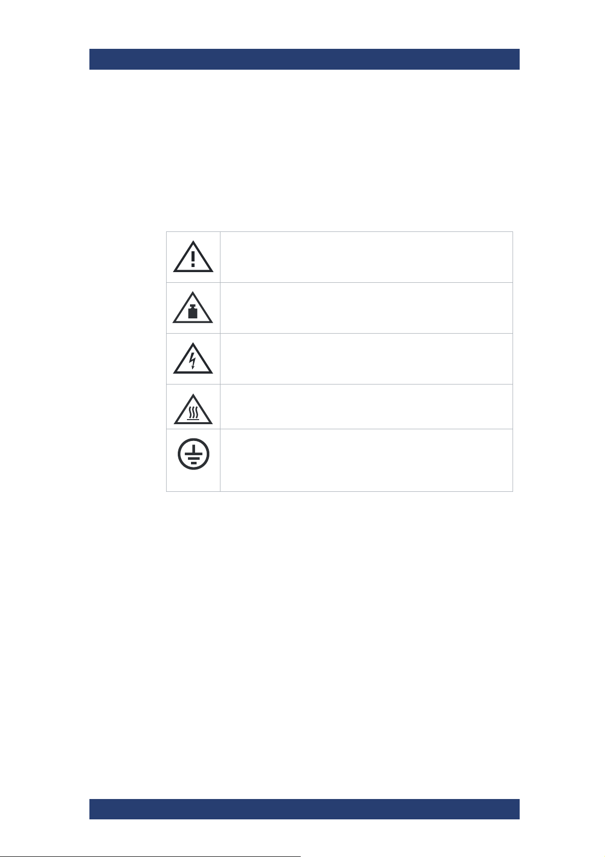
Meaning of Safety Labels
Safety labels on the product warn against potential hazards.
Potential hazard
Read the product documentation to avoid personal injury or product
damage.
Heavy product
Be careful when lifting, moving or carrying the product. Carrying the
product requires at least two people or transport equipment.
Electrical hazard
Indicates live parts. Risk of electric shock, fire, personal injury or even
death.
Hot surface
Do not touch. Risk of skin burns. Risk of fire.
Protective conductor terminal
Connect this terminal to a grounded external conductor or to protective
ground. This protects you against electric shock should an electric
problem occur.
Handling Batteries Safely
The product contains lithium polymer or lithium ion cells or batteries. The use
of the word battery in the following always means all types. Only the battery
contents are potentially hazardous. As long as a battery is undamaged and
the seals remain intact, there is no danger.
Impact, shock or heat can cause damage such as dents, punctures and
other deformations. A damaged battery poses a risk of personal injury.
Handle a damaged or leaking battery with extreme care. Immediately ventilate the area since the battery releases harmful gases. If you come into
contact with the battery fluid, immediately remove all contaminated clothing.
Irritation can occur if the battery fluid comes in contact with your skin or
eyes. Immediately and thoroughly rinse your skin or eyes with water and
seek medical aid.
For safe handling, follow these rules:
● Do not short-circuit the battery.
User Manual (Hardware) | 2904.4460.02 - 04
11
Page 12

Safety and Regulatory Information
Labels on the Product
● Do not mechanically damage the battery. Do not open or disassemble
the battery.
● Do not expose the battery to high temperatures such as open flames, hot
surfaces and sunlight.
● Only use the battery with the designated product.
● Only use the appropriate charger to charge the batteries. If the batteries
are improperly charged, there is a risk of explosion.
● Store the battery at room temperature (approximately 20°C | 68°F)
enclosed in the original packaging.
● Dispose of batteries separately from normal household waste as speci-
fied by the local waste disposal agency.
If you disregard these safety regulations, you risk serious personal injury or
even death due to explosion, fire or hazardous chemical substances
When replacing a defective battery, only use the same battery type. When
returning batteries to Rohde & Schwarz subsidiaries, choose a carrier qualified to transport dangerous goods and follow the carrier’s transport stipulations in line with IATA-DGR, IMDG-Code, ADR or RID. If you need
assistance, contact the carrier or customer service.
CLIPSTER
California, USA Only
The Lithium battery adopted on the motherboard of this system contains
Perchlorate, a toxic substance controlled in Perchlorate Best Management
Practices (BMP) regulations passed by the California Legislature.
When you discard the Lithium battery in California, USA, please follow the
related regulations in advance. Perchlorate Material-special handling may
apply, see www.dtsc.ca.gov/hazardouswaste/ perchlorate.
Labels on the Product
Labels on the casing inform about:
● Personal safety, see "Meaning of Safety Labels" on page 11
● Product and environment safety, see table below.
● Identification of the product
Labels regarding product and environment safety
Labeling in line with EN 50419 for disposal of electrical and electronic
equipment after the product has come to the end of its service life. For
more information, see "Disposal" on page 60.
12
User Manual (Hardware) | 2904.4460.02 - 04
Page 13

CLIPSTER
Safety and Regulatory Information
Warning Messages in the Documentation
Warning Messages in the Documentation
A warning message points out a risk or danger that you need to be aware of.
The signal word indicates the severity of the safety hazard and how likely it
will occur if you do not follow the safety precautions.
DANGER
Imminently hazardous situation. Will result in death or serious injury if not
avoided.
WARNING
Potentially hazardous situation. Could result in death or serious injury if not
avoided.
CAUTION
Potentially hazardous situation. Could result in minor or moderate injury if
not avoided.
NOTICE
Potential risks of damage. Could result in damage to the supported product
or to other property.
Korea Certification Class A
이 기기는 업무용 (A 급 ) 전자파 적합기기로서 판매자 또는 사용자는 이 점
을 주의하시기 바라며 , 가정외의 지역에서 사용하는 것을 목적으로 합니다 .
User Manual (Hardware) | 2904.4460.02 - 04
13
Page 14

Safety and Regulatory Information
CE Declaration of Conformity
CE
Declaration of
Conformity
CLIPSTER
14
User Manual (Hardware) | 2904.4460.02 - 04
Page 15

CLIPSTER
Declaration of Conformity
ROHDE & SCHWARZ GmbH & Co. KG
Mühldorfstr. 15, D-81671 Munich
Munich, 2021-12-02
3632.1307.22
01.00
FCC SDoC
EN
Page 1 / 1
Manufacturer:
Rohde & Schwarz GmbH & Co. KG
Mühldorfstraße 15
81671 München, Germany
Model:
CLP-6MK2
This device complies with Part 15 of the FCC Rules.
Operation is subject to the following to conditions:
(1) This device may not cause harmful interference, and
(2) This device must accept any interference received, including interference that may cause
undesired operation.
Classification:
Class A Digital Device subject to Part 15
We hereby declare that the equipment bearing the trade name and model number specified above was
tested conforming to the applicable FCC rules under the most accurate measurement standards possible,
and that the necessary steps have been taken and are in force to assure that production units of the same
equipment will continue to comply with the Commission’s requirements.
U.S. Responsible Party:
Rohde & Schwarz USA, Inc.
6821 Benjamin Franklin Drive
Columbia, MD 21046
Contact:
Safety and Regulatory Information
FC Declaration of Conformity
FC Declaration of Conformity
User Manual (Hardware) | 2904.4460.02 - 04
15
Page 16

Safety and Regulatory Information
FC Declaration of Conformity
CLIPSTER
16
User Manual (Hardware) | 2904.4460.02 - 04
Page 17
CLIPSTER
Product Description
CLIPSTER is a powerful high-resolution video workstation with enormous
flexibility, designed to meet the demands of modern post production workflows. CLIPSTER processes both compressed and uncompressed single
image and container files in any resolution up to 4K in RGB 16 bit as well as
numerous audio and metadata formats. Arbitrary combinations of codecs,
resolution, bit depth and color volume can be assembled on the timeline and
will be processed without mezzanine conversion to the designated output
format, ensuring the preservation of quality and creative intent.
The hardware allows for real-time in- and output of monoscopic or stereoscopic video in combination with up to 16 channels of audio.
This chapter is divided into following sections:
● Overview of the Front (page 17)
● Overview of the Rear (page 21)
● Important Notes (page 31)
Product Description
Overview of the Front
Overview of the Front
This section gives an overview of the front of the system.
The following topics are covered:
● Front Cover (page 17)
● The Front of the System (page 18)
● Operation Panel (page 19)
● SSD Disk Array (page 20)
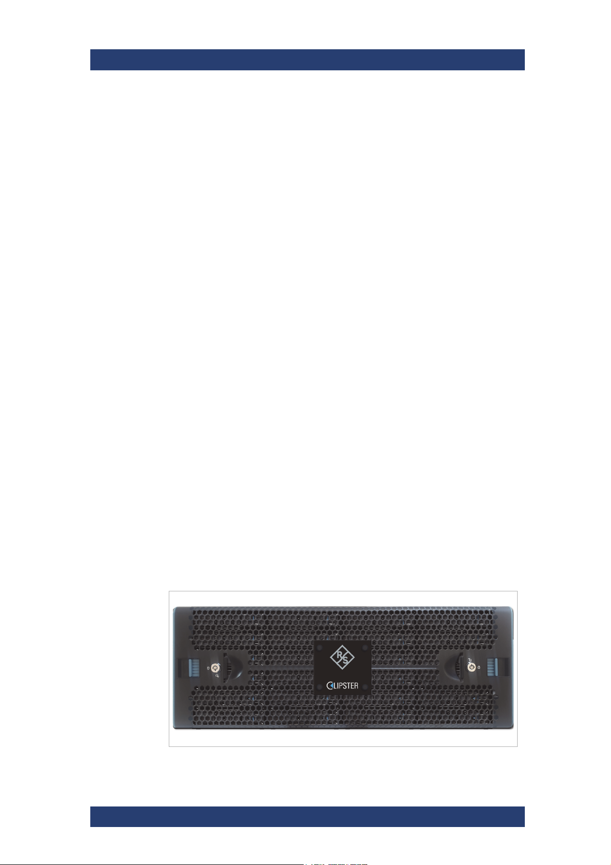
Front Cover
The front of the system is equipped with a front cover for mechanical protection and sufficient air circulation.
CLIPSTER chassis front view
User Manual (Hardware) | 2904.4460.02 - 04
17
Page 18
Product Description
1 2 3
Overview of the Front
The front plate covers the SSD disk array, and the operating panel. If you
need access to one of the SSD disks, or to the operating elements, the front
plate has to be unlocked and removed, see also "Removing the Front Cover"
(page 46).
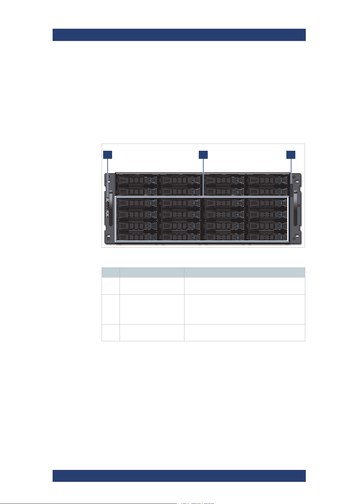
The Front of the System
Once the front cover is removed you have access to the operation panel, the
SSD disk array and the USB ports:
CLIPSTER
Front view without front cover
Operation items
No. Item Description
1 Operation Panel Provides access to all operating items, see
2 SSD Disk Array When purchased with an internal storage option,
3 USB 3.0 Ports 2 x USB 3.0 Type A port to connect external
"Operation Panel" (page 19)
the Solid State Disks will be mounted in these
drive trays. See also "SSD Disk Array"
(page 20).
devices to the system.
18
User Manual (Hardware) | 2904.4460.02 - 04
Page 19
CLIPSTER
Power Button
Power Status LED
Drive Activity LED
LAN Activity LED
System Alert LED
System ID LED
System ID Button
System Reset Button
Product Description
Overview of the Front
Operation Panel
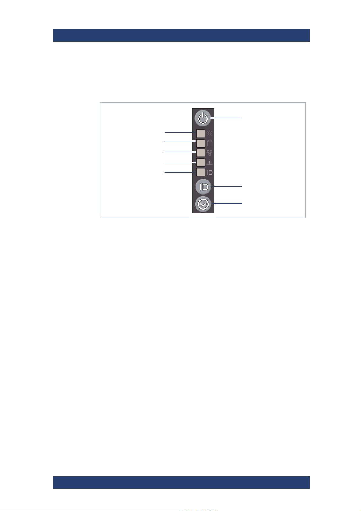
With the operation items at the system’s front the hardware of CLIPSTER
can be controlled (e.g. turned on or off). There you can also find LEDs that
allow you to assess the state of the system.
Operation Items
The System ID Button is linked to the ID button on the ATX connector panel
on the rear of the system (see "ATX Panel" on page 27). Pressing either
button once will illuminate the System ID LED on the Front Operation Panel
and an LED located inside of the ID button on the rear. Pressing either
button again will turn both LEDs off.
User Manual (Hardware) | 2904.4460.02 - 04
19
Page 20
Product Description
SSD disk array
Activity LED
Error LED
Overview of the Front
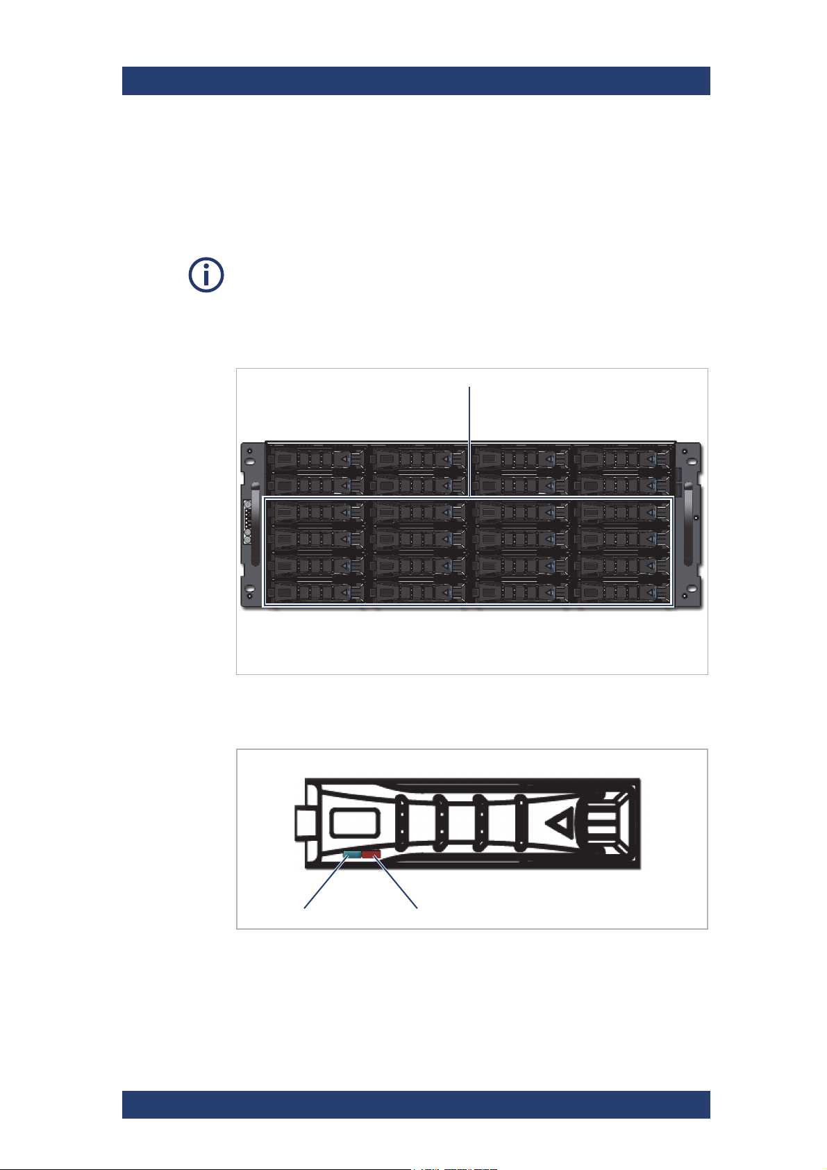
SSD Disk Array
The SSD disks of the disk array are used to store your video and audio data.
It is the main storage of the R&S system. To prevent data loss in case an
SSD disk fails, it is RAID protected.
Further information about RAID can be found in section “RAID Storage Protection” on page 45.
The system disks are not among the SSD disks of the SSD disk array. They
are installed on the back of the system.
Once the front cover is removed, you have access to the SSD disk array:
CLIPSTER
SSD disk array
The status of a single disk is indicated by two LEDs on the front of the disk
carrier:
Status LEDs on Disk Drive
20
User Manual (Hardware) | 2904.4460.02 - 04
Page 21

CLIPSTER
Product Description
Overview of the Rear
Activity LED ON Disk is present
Blinking Disk activity is detected or disk is being
currently located.
OFF Not connected or power is off.
Error LED OFF Idle
Blinking Indicates a failure/repair/maintenance
state such as rebuild, remap, abort
process, etc.
ON Disk complete failure.
For information on how to remove the front cover, see section “Removing the
Front Cover” on page 46.
Further information about how to remove and exchange an SSD disk can be
found in section “SSD Disk Maintenance” on page 44.
Overview of the Rear
This section describes the rear of the system.
The following topics are covered:
● The Rear of the System (page 22)
● Main Connector Panel (page 23)
● Digital Video I/Os (page 24)
● ATX Panel (page 27)
● Slot Panel Connectors (page 28)
● Power Supply (page 30)
User Manual (Hardware) | 2904.4460.02 - 04
21
Page 22
Product Description
1
2
3 4 5
Overview of the Rear
The Rear of the System
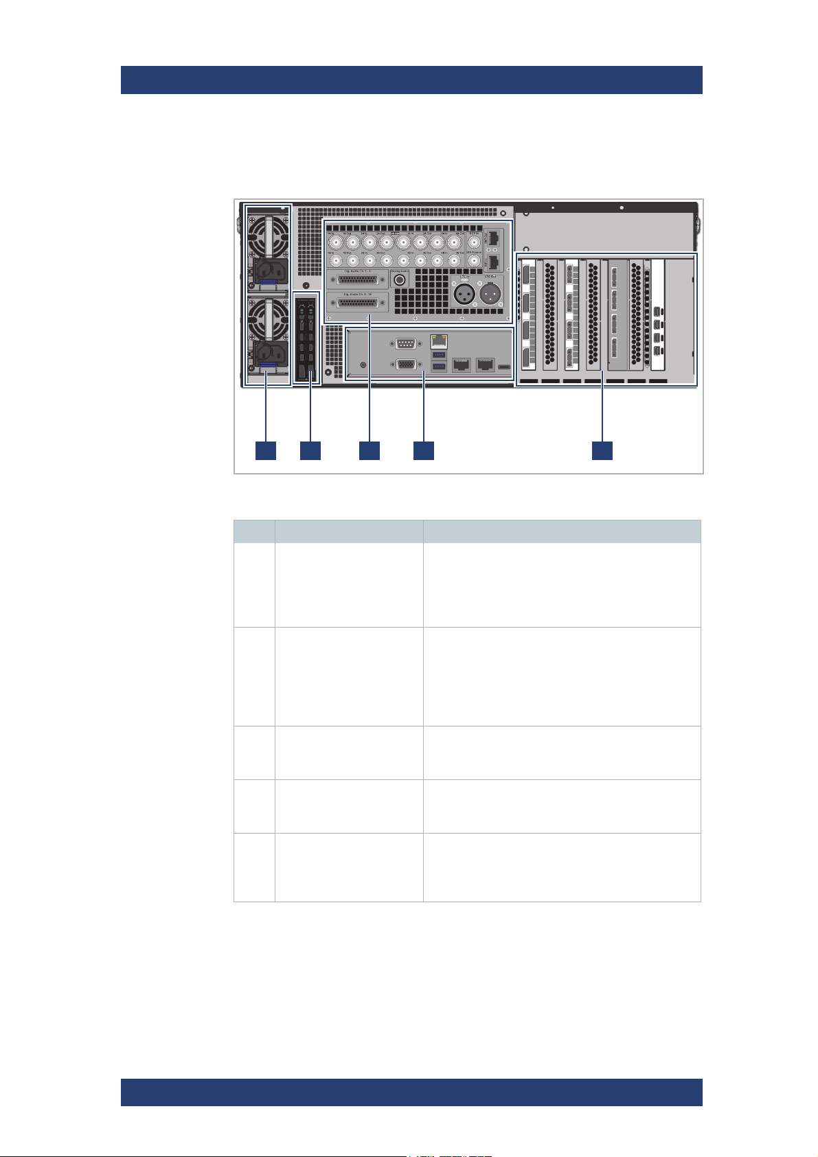
This section provides an overview of the rear of the system.
CLIPSTER
Rear view
Operation items
No. Item Description
1 Power Supply Units 2 x 1600W redundant power supply. Even if one
fails the other will still supply enough power to
keep the system operational. Further information
about the power supply can be found in "Power
Supply" (page 30).
2 System and Backup
Drives
3 Main Connector Panel The main connector panel provides interfaces for
4 ATX Connector Panel On this panel you can find the standard connec-
5 Slot Panel Connectors Additional PCIe board interfaces, e.g. to connect
The left drive tray, located closer to the PSU
modules, is supposed to contain the SSD with
the System Backup Image. The right drive tray,
located closer to the Main Connector Panel, is
supposed to contain the SSD the active Operating System is booted from.
connections to peripheral A/V equipment see
"Main Connector Panel" (page 23).
tors of the computer system, see "ATX Panel"
(page 27).
to GUI monitors or to external storage devices,
are located in this area. For more information see
"Slot Panel Connectors" (page 28)
22
User Manual (Hardware) | 2904.4460.02 - 04
Page 23
CLIPSTER
Product Description
Overview of the Rear
Main Connector Panel
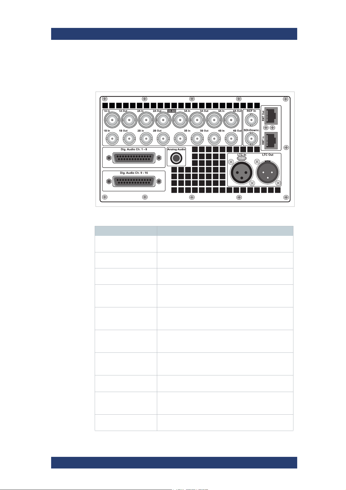
Peripheral equipment can be connected to the CLIPSTER workstation using
the interfaces located on the main connector panel.
Main connector panel
Item Description
LTC In
LTC O ut XLR connector (male) for an output of longitudinal time-
Analog
Audio
Digital Audio Ch. 1-8 DB-25 connector (female) for a balanced audio signal in-
Digital Audio Ch. 9-16 DB-25 connector (female) for a balanced audio signal in-
RJ-45 Top RMT-1: Serial interface for input / output of control
RJ-45 Bottom RMT-2: Serial interface for input / output of control
XLR connector (female) for an input of longitudinal timecode
code
6.3 mm (¼") unbalanced analog stereo headphone jack
to monitor the audio of CLIPSTER.
and output of the digital audio channels 1 to 8
(AES/EBU).
and output of the digital audio channels 9 to 16
(AES/EBU).
signals using the RS-422 protocol, see "RMT In and RMT
Out (RJ-45)" (page 68).
signals using the RS-422 protocol, see "RMT In and RMT
Out (RJ-45)" (page 68).
HD-SDI In/Out BNC connectors for input/output of digital HD video
signals, see also "Digital Video I/Os" below.
REF In BNC connector for a synchronization of video signals, i.e.
the reference input; input of horizontal or composite sync
depending on software settings
SDI Downconvert BNC connector for down-scaled SDI signal from UHD/4K
to 1080p/2K. The frame rate (up to 60 Hz) is not affected.
User Manual (Hardware) | 2904.4460.02 - 04
23
Page 24
Product Description
Overview of the Rear
Pin-outs of most connectors can be found in section “Signal In- and Outputs”
on page 67.
For the availability of connectors not present at the rear of the system (blind
panels) please contact Rohde & Schwarz.
Digital Video I/Os
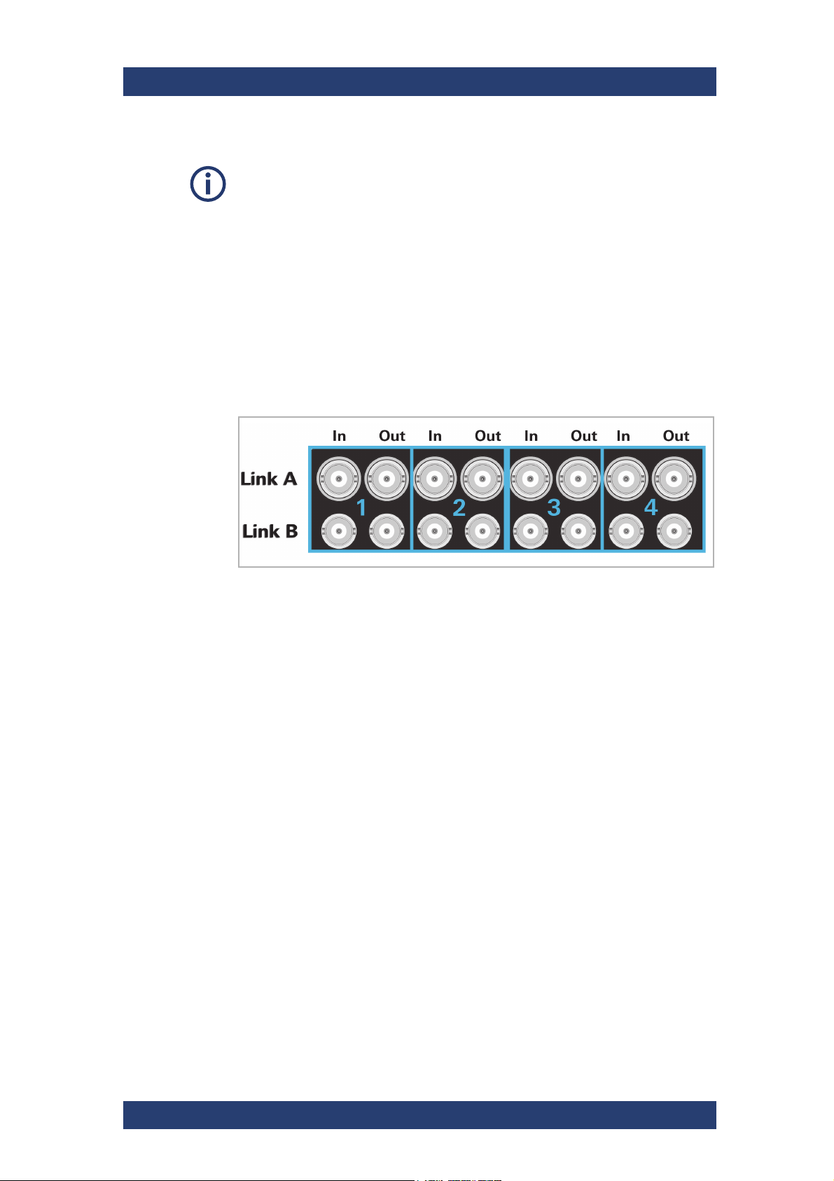
CLIPSTER supports several SDI modes, which can be selected through the
user interface in the software. Different SDI modes may require different
connections to the digital video I/Os located on the main connector panel.
The I/O ports are divided into four quadrants, each of them having a row for
the A and B links as well as two In and Out ports.
CLIPSTER
SDI general layout
R&S names the input/output ports of the digital video signals alphabetically:
the main video link is available on the A ports and the secondary video link
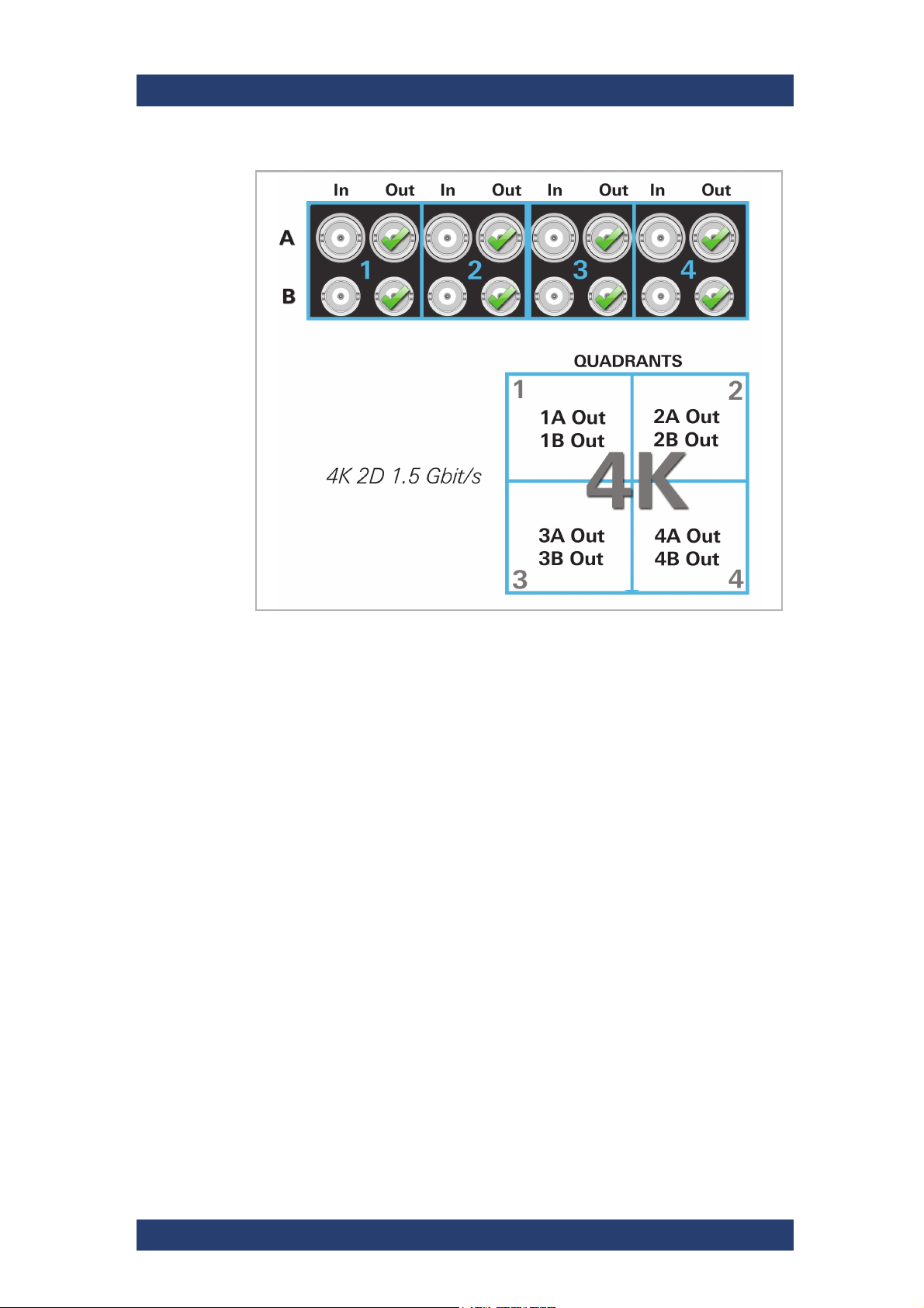
on the B ports. The numbers specify the quadrant those ports belong to. For
example, a connection of 4K 1.5-Gbit/s SDI output will have the following
layout:
24
User Manual (Hardware) | 2904.4460.02 - 04
Page 25
CLIPSTER
Product Description
Overview of the Rear
Layout of 4K SDI output at 1.5 Gbit/s
For in- and output CLIPSTER also supports 3-Gbit/s SDI which provides all
features of a standard dual-link connection, but requires only one connector
instead of two (SMPTE 425, level A and B). In the example above, only the
A ports would be connected. A 3-Gbit/s input signal can be automatically
detected by the software. For an output it has to be enabled via the software.
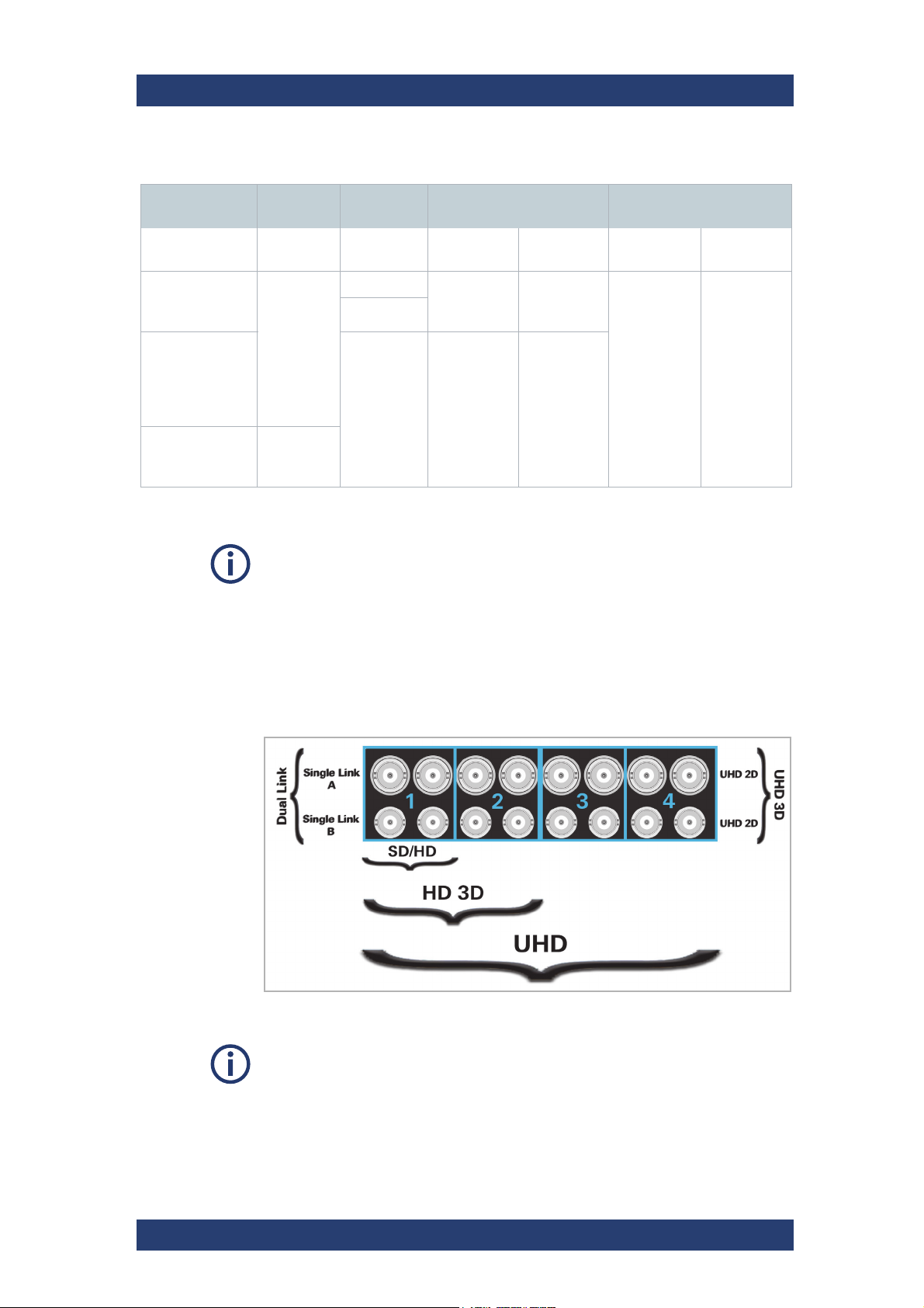
The following table gives an overview on the signal assignment on the SDI
(serial digital interface) for different color modes and with a different connection speed (SDTV, 1.5 Gbit/s and 3 Gbit) considering also the fps:
User Manual (Hardware) | 2904.4460.02 - 04
25
Page 26
Product Description
Overview of the Rear
SDI supported data formats
Color Mode Bit Depth Frame Rate
24 - 30 "A"
YUV 4:2:2
48 -60
(Hz)
1.5G Link 3G Link
Monoscopic
(2D)
connector
Stereo scopic (3D)
"A"+"B"
connector
Monoscopic
(2D)
CLIPSTER
Stereoscopic (3D)
YUV 4:4:4
RGB 4:4:4
YUVA 4:2:2:4
YUVA 4:4:4:4
RGBA 4:4:4:4
YUV 4:2:2
YUV 4:4:4
RGB 4:4:4
10
12
24 - 30 "A"+"B"
connector
n/a
"A"
connector
"A"+"B"
connector
The type of video link used (single or dual) depends on the SDI mode, the fps
mode applied and the selected connection speed.
In case of working with stereoscopic material, for input the user has to select
special rasters in the software (I/O Tool) tagged with STEREO. For an
output, the option dual stream must be selected in the user interface. The
selected raster will be output at two ports (A+B) if available for the 3D
stereoscopic workflow. The video stream assignment for left and right eye
can be configured in the software.
26
Layout of the Quadrants
The selected resolution determines the number of quadrants in use.
User Manual (Hardware) | 2904.4460.02 - 04
Page 27
CLIPSTER
VGA
2 x USB 3.1 Gen1
2 x LAN RJ-45, 10Gbit
COM1 port
LAN RJ-45 (IPMI), 1Gbit
USB 3.1 Gen2 (type C)
System ID
Indicator
Product Description
Overview of the Rear
ATX Panel
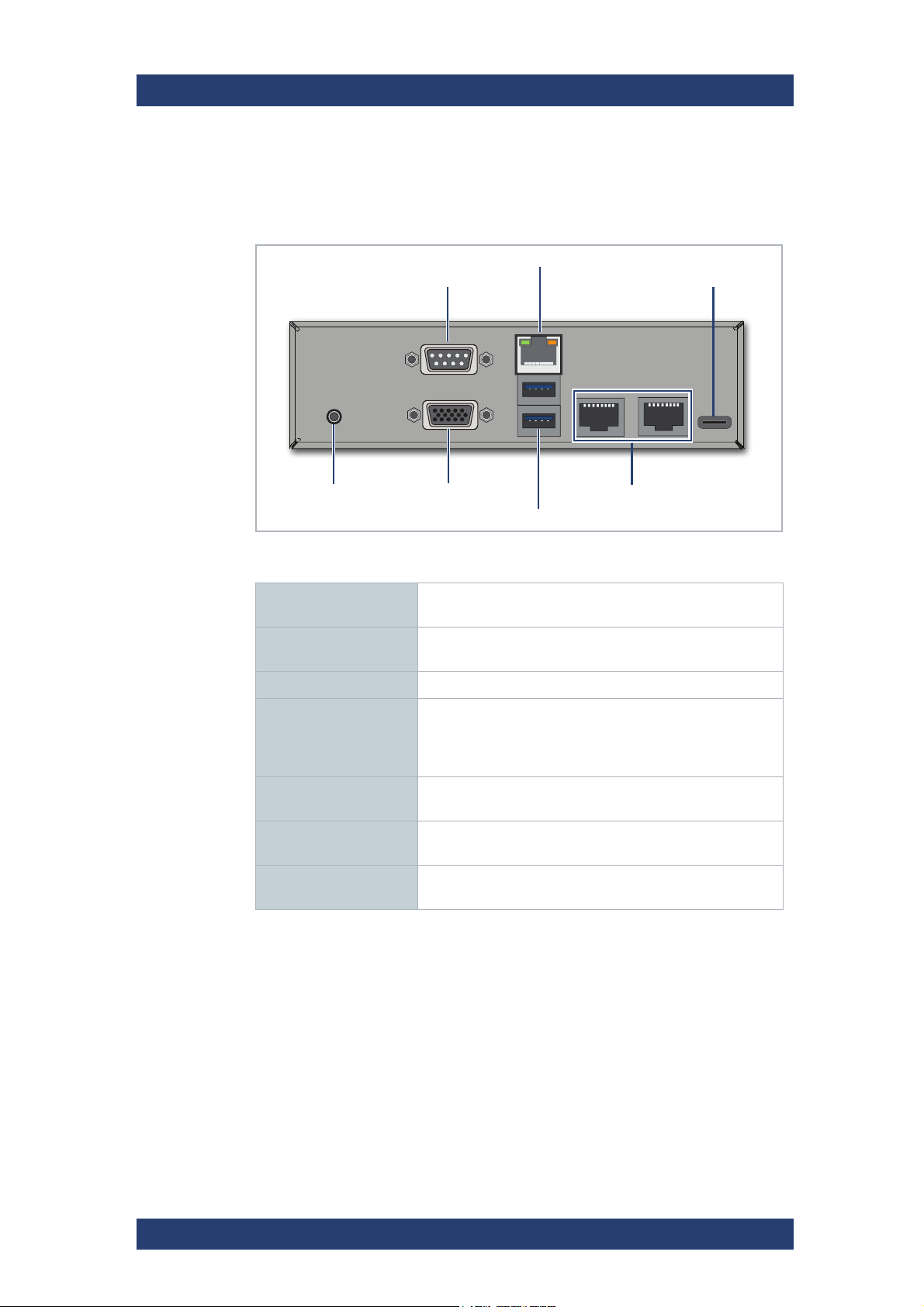
The ATX connector panel on the rear of the R&S system holds the connectors of the computer system. It provides the following connections:
ATX Panel Connectors
COM1 Port RS232 connector for the connection of serial interface
devices.
LAN RJ-45 (IPMI) 1 Gb Ethernet connection port to connect the system to a
network.
USB 3.1 Gen2 (type C) A type-C USB to connect external devices to the system.
System ID Indicator Press to trigger the ID LED located on the front of the
system. Useful e.g. to locate the system within a rack
among many other systems, see also informative section
in "Operation Panel" on page 19.
VGA DB-15 connector (female) to connect a monitor to the
system.
USB 3.1 Gen1 USB connectors to connect external devices to the
system.
2 x LAN RJ-45 2 x 10 Gb Ethernet connection ports to connect the
system to a network.
User Manual (Hardware) | 2904.4460.02 - 04
27
Page 28
Product Description
1
2
3 4
5
6
Overview of the Rear
Slot Panel Connectors
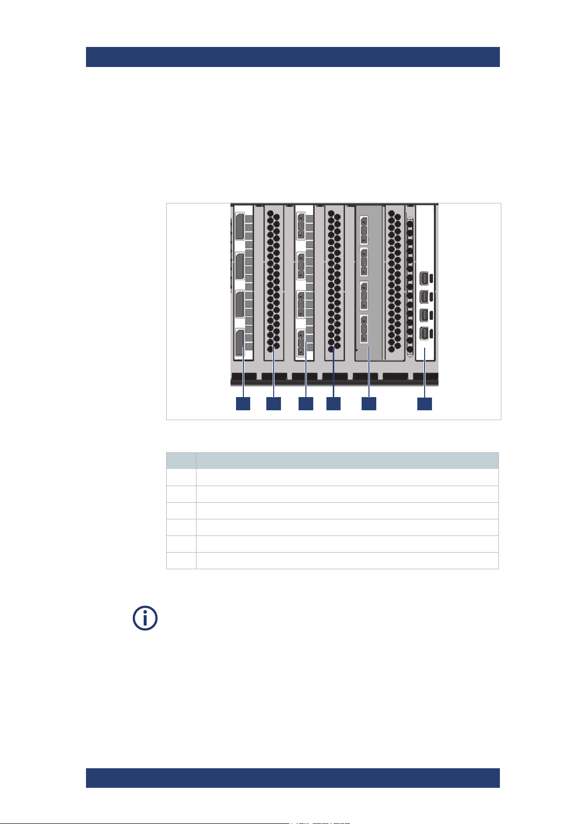
CLIPSTER provides on its slot panel connector area various connections,
such as the graphics card panel and the video I/O panel. Furthermore, if
applicable, some additional panels may be present for internal reasons or on
customer request.
Overview
CLIPSTER
Slot panels on rear
No Name
1 Option slot for JPEG2000 de-/encoding accelerator
2 Options slot for either a 100 GB network adapter or Fiber Channel
3 Video output panel (4 x DisplayPort or HDMI 2.0 via adapters).
4 Option slot for internal RAID controller.
5 Option slot for floating point processing unit (GPU)
6 Video graphics card to connect a display to your system
The layout of the slot panel area on your system may differ from the figure
above: The position of the individual slot panels may vary and additional panels may be installed for internal reasons or on customer request.
28
User Manual (Hardware) | 2904.4460.02 - 04
Page 29
CLIPSTER
3
1
2
4
Product Description
Overview of the Rear
Video Panel
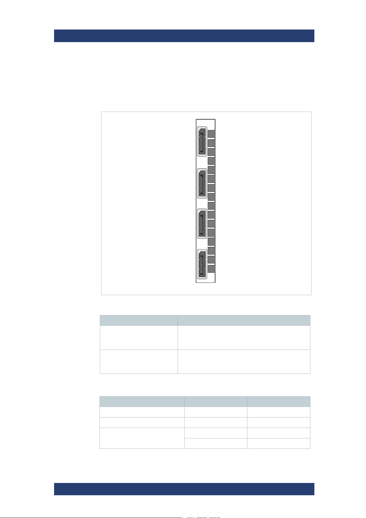
The video output panel of CLIPSTER holds four video interfaces (DisplayPort by default, or HDMI 2.0 via adapters) for an output of digital video
signals. Pin-outs of the connectors can be found in "Signal In- and Outputs"
(page 67).
Video I/O panel
Item Description
DisplayPort DisplayPort connector for an output of digital RGB
video signals (quadrants 1/2, either two independent
single-link or one dual-link connection)
DisplayPort DisplayPort connector for an output of digital RGB
HDMI 2.0 supported data formats (via optional adapter 2904.1060.03)
Color mode Bit Depth FPS
YUV 4:2:0 8bit up to 60p
YUV 4:2:2 8, 10, 12 bit up to 60p
RGB 8bit up to 60p
video signals (quadrants 3/4, either two independent
single-link or one dual-link connection)
10, 12 bit up to 30p
User Manual (Hardware) | 2904.4460.02 - 04
29
Page 30
Product Description
Overview of the Rear
Graphics Card
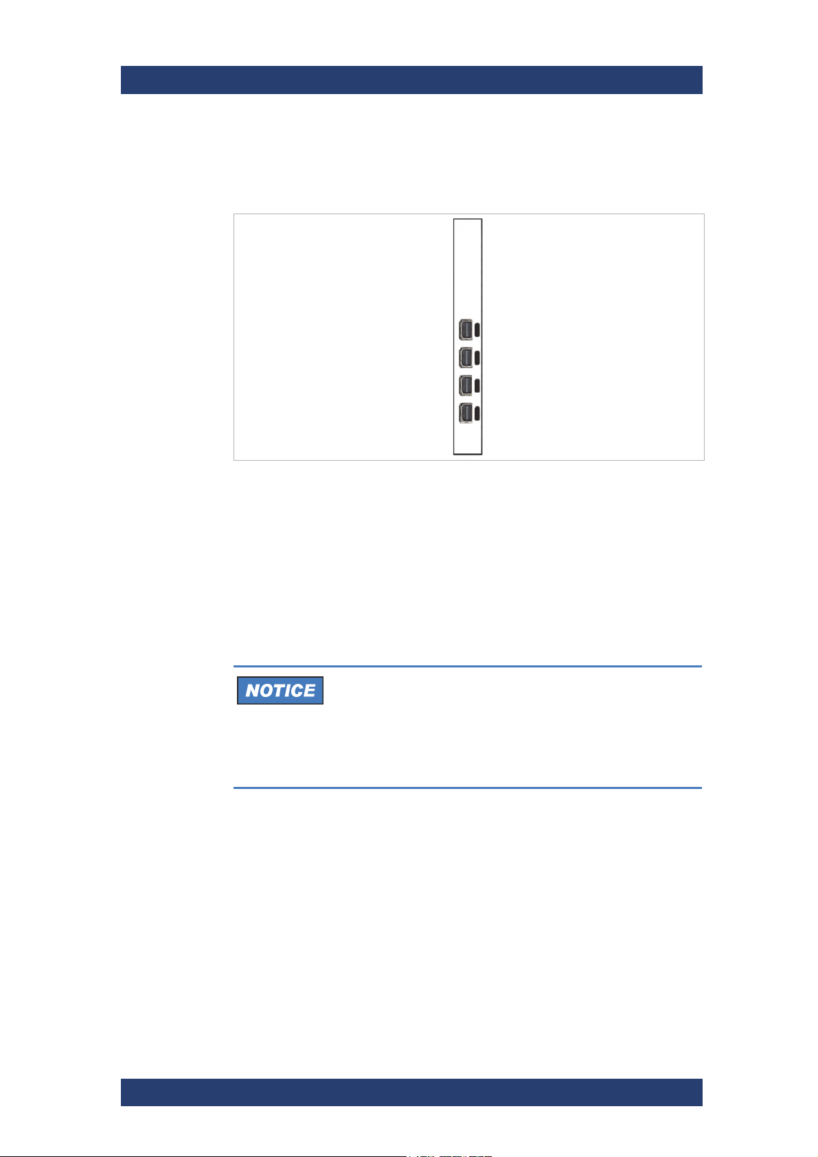
The monitor for the CLIPSTER
panel provides four Mini-DisplayPort connections.
Graphics Card
CLIPSTER
software has to be connected here. The
For further information about the graphics card, please refer to the original
manufacturer’s documentation.
Power Supply
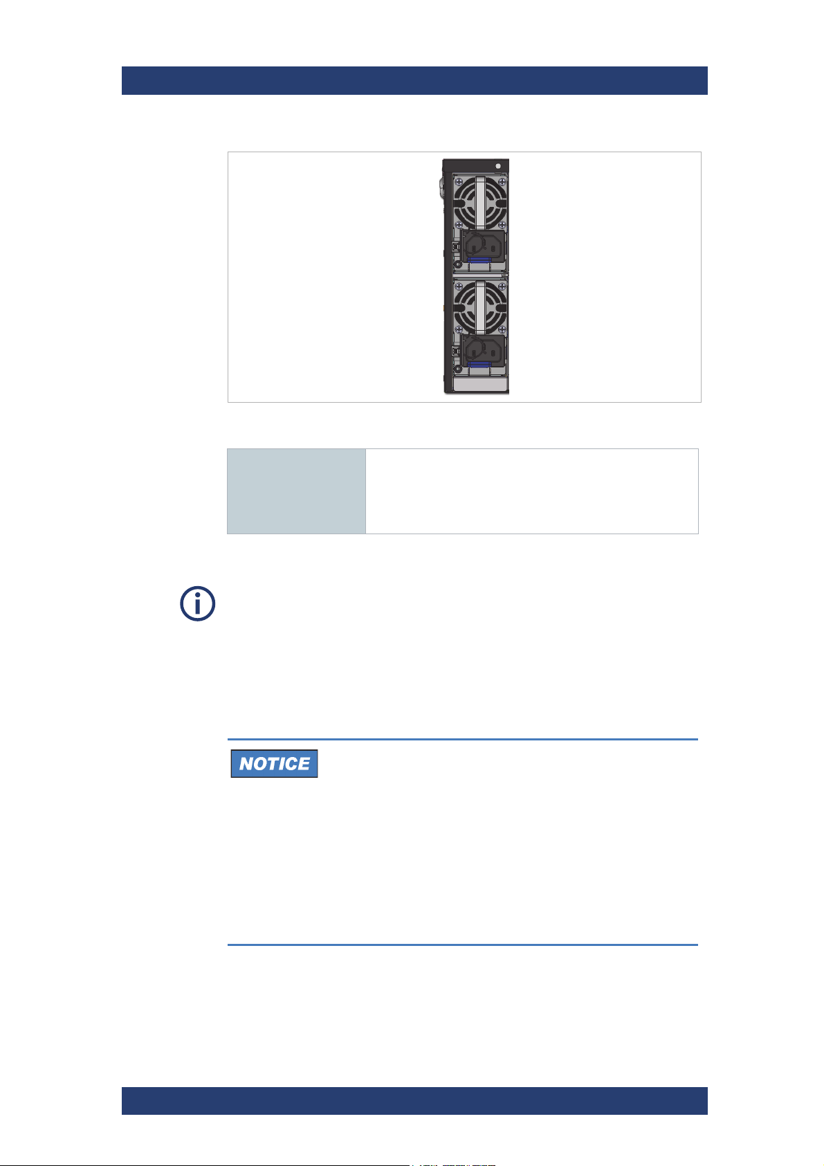
The redundant power supply consists of two independent power supply
modules: Even if one fails, the other should output sufficient current to keep
the system working.
System Damage
The system can be operated with one power supply unit out
of order. However, if the other one fails, a continued operation of the system cannot be guaranteed.
Change a failed power supply unit immediately (see
section “Power Supply Maintenance” on page 58).
30
User Manual (Hardware) | 2904.4460.02 - 04
Page 31
CLIPSTER
Product Description
Important Notes
Power supply units
Power supply 1600W 1+1 redundant power supply
• AC INPUT:
- 100..127V, 50..60Hz, 13A
- 200..240V, 50..60Hz, 10A
• The IEC C14 AC connector requires a C13 AC jack.
To pull out a power supply unit you have to remove the security bar of the
power supply first, see section “Power Supply Maintenance” on page 58.
Important Notes
Please observe the following general important notes:
Performance Loss
This system has been delivered to you fully preconfigured
and optimized for a real-time in- and output of uncompressed video streams. Changing any of the settings (e.g.
the hardware, software and/or BIOS settings) may lead to a
loss of performance or may even render the system unusable. Re-configuring the system anew is in most cases a
lengthy procedure.
Do not change any of the settings unless you are absolutely sure of what you are doing and what the results
would be.
User Manual (Hardware) | 2904.4460.02 - 04
31
Page 32
Product Description
Important Notes
CLIPSTER
Windows Updates
So far there are no known issues with Windows updates
provided by Microsoft and we do recommend installing
those patches. However, Rohde & Schwarz cannot be held
responsible for unexpected problems arising due to updates
of the operating system.
It is the customer‘s responsibility to update the
Windows operating system and install security patches.
Third-party Software
Your R&S system has been tested thoroughly to ensure its
reliability when running R&S software. The effects of installation and use of third party software and drivers may
disrupt the real-time capability and/or limit the functionality
of your system.
SSD Power Supply
Leaving the system without power supply for long periods of
time may have adverse effect on the SSD storage.
We recommend not leaving the system without power
supply for long periods of time.
Designated Data Storage Locations
Other data storage locations may only provide insufficient
bandwidth and latency for real-time operations.
Only use the designated data storage locations to store
video and audio data.
Potential Video Board Oil Leak
The heat-conducting pads enclosed in the air duct of the
video board may leak some oil over time due to the
mechanical process involved. This does not lead to any
deterioration of the cooling performance, and any potential
leakage of this oil film will not affect CLIPSTER‘s functionality in any way.
32
User Manual (Hardware) | 2904.4460.02 - 04
Page 33
CLIPSTER
Installation and Operation
This chapter describes the installation and operation of the CLIPSTER hardware. The system must be installed properly before you can start working
with it.
This chapter is divided into the following topics:
● Unpacking the System (page 33)
● Mounting the System into a Rack (page 34)
● Connecting Monitor, Mouse and Keyboard (page 38)
● Operating the System (page 39)
Lifting and Carrying
Installation and Operation
Lifting and Carrying
Risk of Injury
Lifting the system by yourself may result in serious injury and property
damage.
Do not attempt to lift the system by yourself, always get others to
assist you.
We recommend to use lifting equipment, see also "Lifting and Carrying the
Product" on page 8.
Unpacking the System
Perform the following steps:
1.
Unpack the product carefully.
2. Retain the original packing material. Use it to protect the control
elements and connectors when transporting or shipping the product later.
3. Check your delivery and compare it with the delivery note. In case of
missing items, please contact your vendor or R&S immediately.
4. Place the system on a flat surface to prepare it for mounting into the
rack.
The system is unpacked and ready for installation.
User Manual (Hardware) | 2904.4460.02 - 04
33
Page 34

Installation and Operation
Choosing the Operating Site
Choosing the Operating Site
Specific operating conditions ensure proper operation and avoid damage to
the product and connected devices. For information on environmental conditions such as ambient temperature and humidity, see the data sheet.
See also "Choosing the Operating Site" on page 9.
Electromagnetic compatibility classes
The electromagnetic compatibility (EMC) class indicates where you can
operate the product. The EMC class of the product is given in the data sheet
under "General data".
● Class B equipment is suitable for use in:
- Residential environments
- Environments that are directly connected to a low-voltage supply
network that supplies residential buildings
● Class A equipment is intended for use in industrial environments. It can
cause radio disturbances in residential environments due to possible
conducted and radiated disturbances. It is therefore not suitable for class
B environments.
CLIPSTER
If class A equipment causes radio disturbances, take appropriate measures
to eliminate them.
Mounting the System into a Rack
The system is to be operated in a 19-inch wide rack.
Rack System Precautions
The following safety requirements must be considered when the unit is
mounted in a rack.
● The rack construction must be capable of supporting the total weight of
the installed enclosure(s) and the design should incorporate stabilizing
features suitable to prevent the rack from tipping or being pushed over
during installation or in normal use.
● The system must be operated with low pressure rear exhaust installation
[back pressure created by rack doors and obstacles not to exceed 5
pascals (0.5mm water gauge)].
● The rack design should take into consideration the maximum operating
ambient temperature for the unit, which is 35°C.
● The rack should have a safe electrical distribution system. It must
provide over-current protection for the unit and must not be overloaded
by the total number of units installed in the rack. When addressing these
concerns consideration should be given to the electrical power consumption rating shown on the nameplate.
● The electrical distribution system must provide a reliable earth for each
unit in the rack.
34
User Manual (Hardware) | 2904.4460.02 - 04
Page 35
CLIPSTER
Installation and Operation
Mounting the System into a Rack
● The design of the electrical distribution system must take into consider-
ation the total earth leakage current from all the power supplies in all the
units. The rack may require labeling with “HIGH LEAKAGE CURRENT.
Earth connection essential before connecting supply”.
● The rack when configured with the units must meet the safety require-
ments of current UL and IEC specifications.
Rack Toppling Over
Racks may topple over due to a massive overweight in the upper part.
Do not slide more than one enclosure out of the rack at a time. When
loading a rack with enclosures, fill from the bottom up; empty from
the top down. Close all enclosures before loading.
Risk of Injury
The weight of the system is around 45kg (99lbs), or more.
Do not attempt to lift the system by yourself, always get others to
assist you.
Mounting the System
Perform the following steps:
1. Make sure the system is unpacked and placed on a flat surface, see
"Unpacking the System" (page 33).
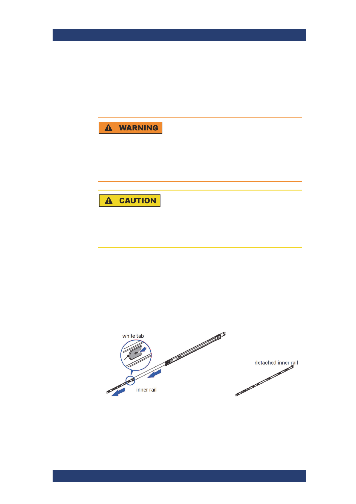
2. Pull the inner rail out of the slide rail until it clicks and detach the inner
rail completely from the slide rail by pulling the tab forward.
User Manual (Hardware) | 2904.4460.02 - 04
35
Page 36
Installation and Operation
Mounting the System into a Rack
After the inner rail is dislodged, adjust the middle rail back to its original
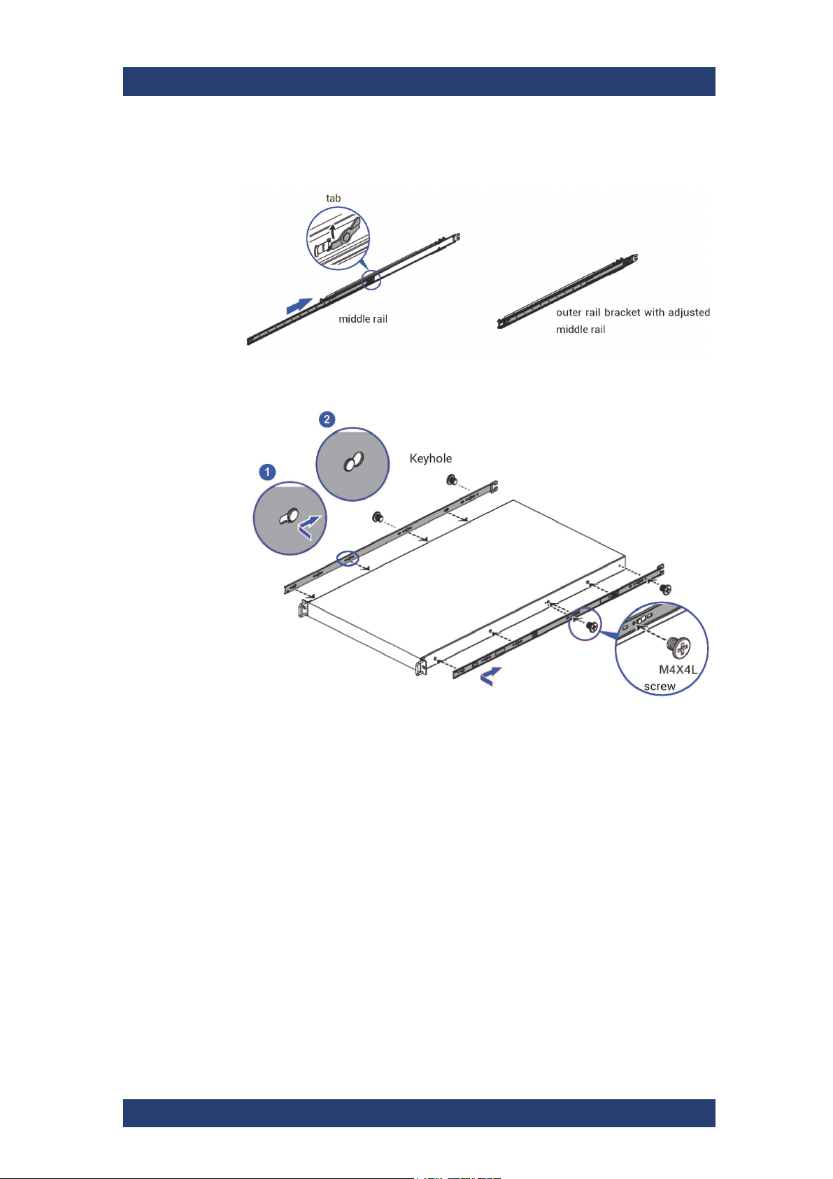
3.
position by pushing the tab on the middle rail.
4. Install the inner rail onto the system casing. Lock the keyholes and
secure the screws.
CLIPSTER
36
User Manual (Hardware) | 2904.4460.02 - 04
Page 37
CLIPSTER
Installation and Operation
Mounting the System into a Rack
5.
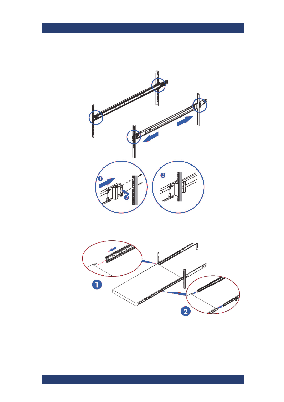
Continue installing the outer rail bracket to the mounting frame. Attach
the outer rail assembly to the frame and press the bracket to fix the rail
onto the frame.
6. Pull out the middle channel until the ball bearing retainer is locked
forward.
7. CAUTION! Verify the ball bearing retainer is locked.
User Manual (Hardware) | 2904.4460.02 - 04
37
Page 38
Installation and Operation
Connecting Monitor, Mouse and Keyboard
Slide the release tab and push the system into the rack.
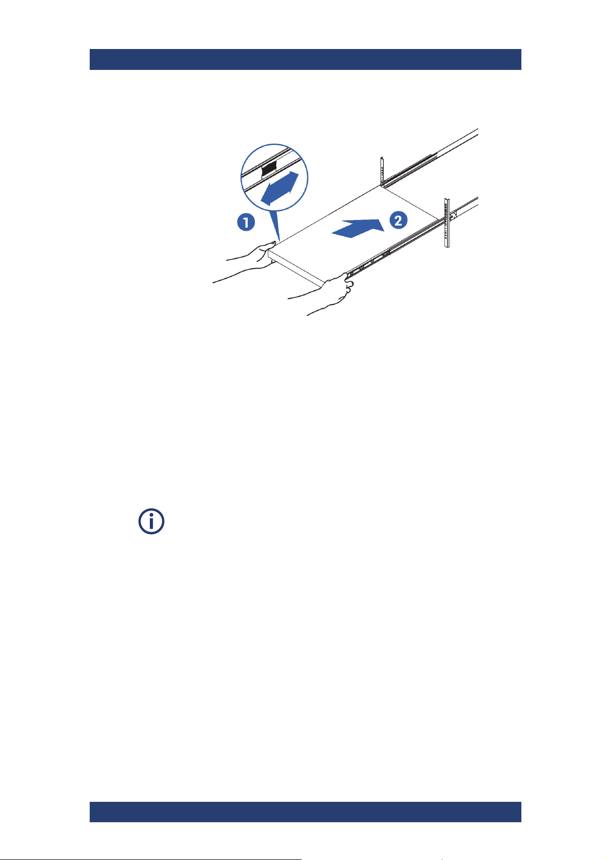
8.
CLIPSTER is now mounted into the rack.
CLIPSTER
Connecting Monitor, Mouse and Keyboard
Perform the following steps:
1. Connect at least the following computer peripherals:
mouse
keyboard and
a monitor that is operable at a resolution of at least 1920 x 1080 pixels
(default manufacturing setting).
The recommended resolution to run the R&S software is between
1920 x 1080 and 2560 x 1440 pixels.
2. Connect any other peripheral computer and video equipment. For an
overview of the panels and connectors at the system’s rear, see section
“Overview of the Rear” on page 21.
38
User Manual (Hardware) | 2904.4460.02 - 04
Page 39
CLIPSTER
Installation and Operation
Connecting to Power
Connecting to Power
For safety information, see "Connecting to Power" on page 9.
Perform the following steps:
1.
Plug the AC power cable into the AC power connector on the rear panel
of the product. Only use the AC power cable delivered with the product.
2. Plug the AC power cable into a power outlet with ground contact. The
required ratings are listed in the data sheet.
3. If necessary, also ground the product using the grounding terminal.
4. Install any other remaining cables before switching on the product.
Operating the System
This chapter describes how to operate the CLIPSTER hardware, i.e. it is
explained how to start the system and how to shut it down. For both procedures you have to use the power switch of the operation items at the front of
the system.
The following topics are covered:
● Starting the System (page 39)
● First Login (page 40)
● Shutting Down the System (page 41)
● IPMI Login (page 42)
Starting the System
After a proper installation of the system you may start the R&S system at
any time.
Perform the following steps:
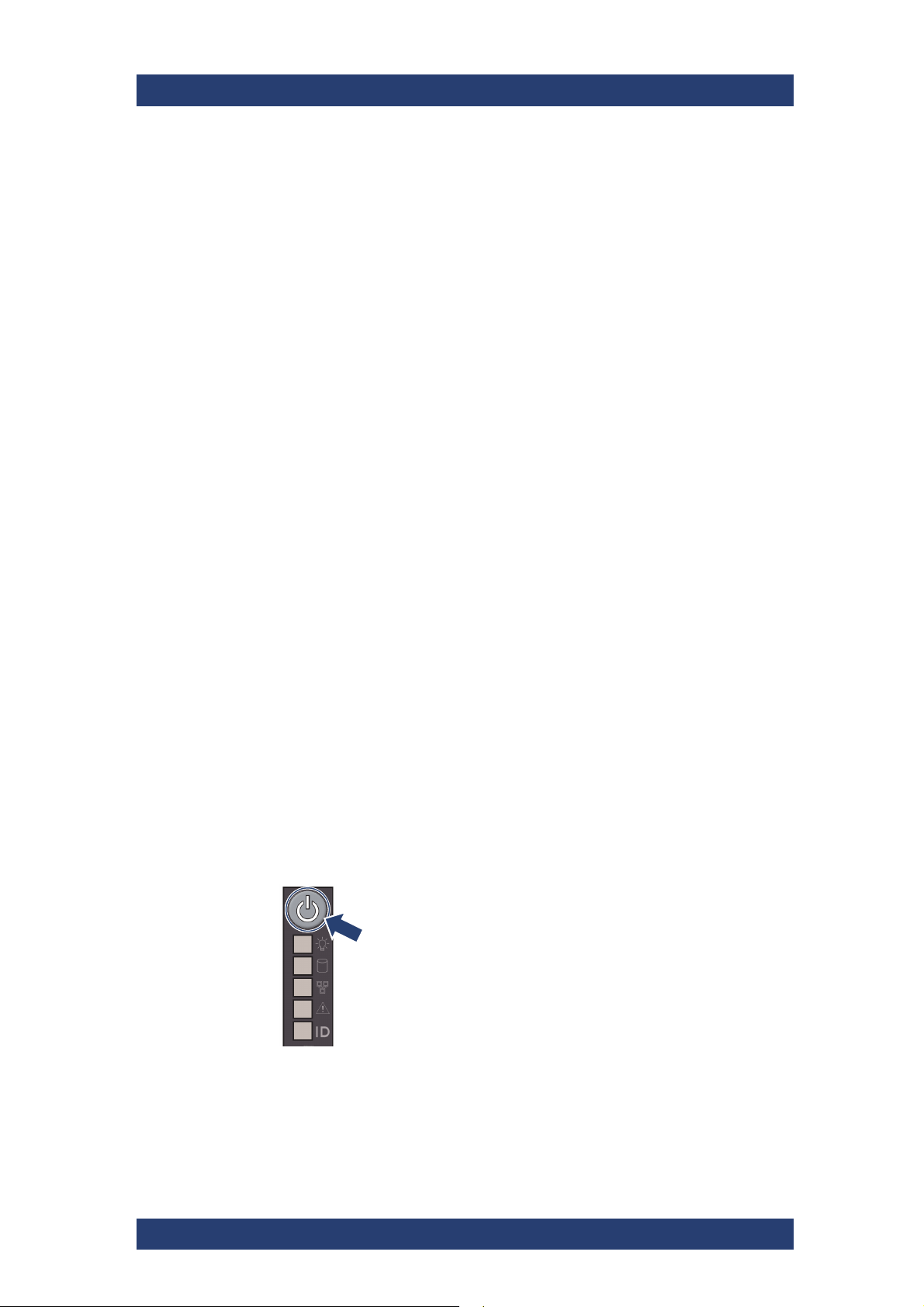
•
Press the power switch to turn on the system.
The system will be started. As with any standard computer after initial
booting, the system begins to load the installed operating system.
When the operating system has finished its loading, you can begin to
work with the R&S system right away.
User Manual (Hardware) | 2904.4460.02 - 04
39
Page 40
Installation and Operation
2
Operating the System
First Login
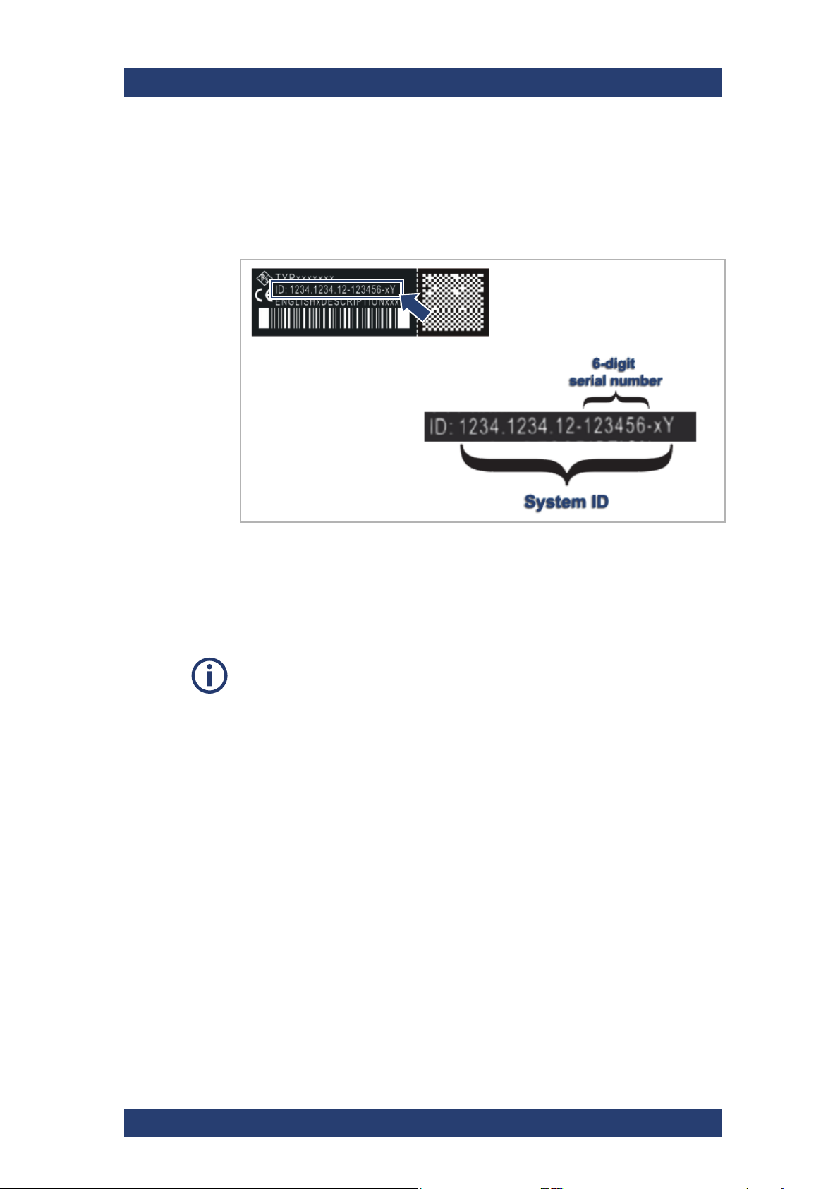
CLIPSTER is shipped with an individual factory default password for the
Windows user account "admin". This password follows the pattern:
win[6-digit serial number of the system].
The serial number of the system is located on the back of the system.
CLIPSTER
Serial number of the system
Please change this password immediately after the first login by pressing
Ctrl+Alt+Delete on your keyboard and selecting Change password from
the menu, or go to Start > Settings > Accounts > Sign-in options.
Under "Password", select the Change button.
For a reasonable level of system security, all user accounts should be set up
with an individual password. The CLIPSTER application only requires a standard Windows user account (not a local admin account), therefore we also
recommend to add one or more standard user accounts to the system to increase system security.
40
User Manual (Hardware) | 2904.4460.02 - 04
Page 41
CLIPSTER
Installation and Operation
Operating the System
Shutting Down the System
There are several possibilities to shut down the system. It depends on
whether the operating system is already loaded, frozen or not completely
loaded. Please act accordingly.
Shut down with operating system fully loaded
If the operating system is up and running, there are two ways to shut down
your system.
System Damage
It takes a while to safely erase all memory banks of the system.
After a shut-down wait at least ten seconds before
starting the system again.
Perform the following steps:
1.
Turn the system off by shutting down the operating system through the
Windows menu.
The operating system will then save your personal settings and once it
has ended, the system will turn off.
2. Alternatively, you can initiate a fast shut down by pressing the power
switch briefly.
Some settings will be saved and afterwards the system turns off.
Data Loss
The fast shut-down may not save all your system data and
personal settings before the system turns off.
System is shut down.
Shut down with operating system frozen or not completely loaded
If the operating system is not responding anymore or not completely loaded,
do as follows:
Corrupted Data
Shutting down the system while frozen or not completely
loaded may lead to corrupted system data.
Use this procedure only if absolutely necessary.
User Manual (Hardware) | 2904.4460.02 - 04
41
Page 42

Installation and Operation
Operating the System
Perform the following steps:
•
Shut down the system by pressing the power switch until the system
turns off.
The system will then shut down immediately.
IPMI Login
The system is accessible and configurable via the IPMI interface. The IPMI
IP address is displayed at boot time. The pre-configured IPMI login name is
"admin", and its password is:
CLIPSTER
ipmi[6-digit serial number of the system]
42
User Manual (Hardware) | 2904.4460.02 - 04
Page 43
CLIPSTER
Maintenance
This chapter explains the maintenance work that you can perform on your
own. For each work a detailed procedure description is given. If you experience trouble with the system that cannot be resolved with the work
described here, please contact your local vendor or Rohde & Schwarz
directly.
This chapter is divided into the following sections:
● Safety during Maintenance (page 43)
● SSD Disk Maintenance (page 44)
● Removing the Top Cover (page 50)
● Recovery of the System Disk (page 51)
● Fan Maintenance (page 55)
● Power Supply Maintenance (page 58)
● Cleaning (page 59)
● Storage (page 59)
● Disposal (page 60)
Maintenance
Safety during Maintenance
Safety during Maintenance
This section provides safety instructions to be especially observed during
maintenance work.
Electronic Discharge
Computer hardware contains components that are sensitive to electrostatic
discharge. If you touch them without precautionary measures, they can be
destroyed.
It is recommended that you fit and check a suitable anti-static wrist or
ankle strap and observe all conventional ESD precautions when
handling plug-in modules and components. Avoid contact with
midplane components and module connectors.
Risk of Cutting Injury
Maintenance inside the system should be performed with caution
especially near internal chassis edges or when working with sharp
hardware components to avoid cuts on fingers, hands or arms. Wear
appropriate protective cloths, when applicable.
User Manual (Hardware) | 2904.4460.02 - 04
43
Page 44
Maintenance
SSD Disk Maintenance
Risk of Burn Injury
Some of the components inside the system could get very hot (e.g. CPU,
PCI cards, etc.) and thus pose danger of burning your skin.
Wait for those components to cool down before maintenance is
started.
Noise Protection
Working in noisy environments may damage your hearing.
When performing maintenance task in loud areas use personal
hearing protective devices, and ensure they are worn correctly.
CLIPSTER
Postural Deformities
Maintenance shall only be done after it was made sure that postural
deformities can not arise from working on the product.
When replacing an electrical module, always have available a replacement or
blank module before removing the old one. When you replace a module, you
must never leave an empty bay in the rear of the enclosure.
SSD Disk Maintenance
This section deals with the possible event of a SSD disk failure.
The following topics are covered:
● RAID Storage Protection (page 45)
● Removing the Front Cover (page 46)
● Identifying a Defective SSD Disk (page 46)
● SSD Disk Replacement (page 47)
● SSD Disk Removal (page 48)
● Replacing the SSD Disk in the Carrier (page 49)
● Reassembling the SSD Disk (page 49)
44
User Manual (Hardware) | 2904.4460.02 - 04
Page 45
CLIPSTER
disk
se
t
2
disk
se
t
1
Maintenance
SSD Disk Maintenance
RAID Storage Protection
In a system with huge amounts of data processed, large storage capacities
combined with high data throughputs are mandatory. To provide both at the
same time it is common practice in the area of video and digital film to
configure several SSD disks together into a stripe set or RAID.
The RAID feature makes the R&S system tolerant of disk failures. Even with
a broken disk operations can still be continued and, once the failed disk has
been replaced, the missing data can be easily recovered. The data protection is provided by a RAID controller installed inside the system. The
controller administers the data protection for the sets of SSD disks
connected to it.
The optional internal storage of the R&S system comprises one or more
SSD disk packs. These are connected to RAID controllers in a RAID 5 setup.
With this, the data is striped across these SSD disks during write procedures. At the same time the information necessary to rebuild a failed disk
(parity information) is generated and written across the disks as well. With
the parity information written, one SSD disk per disk set (RAID pack) can fail
and your data will still be recoverable as the information is stored on the
other disks.
Data Loss
If a second disk within the same disk set fails in the meantime, the data will be unrecoverable.
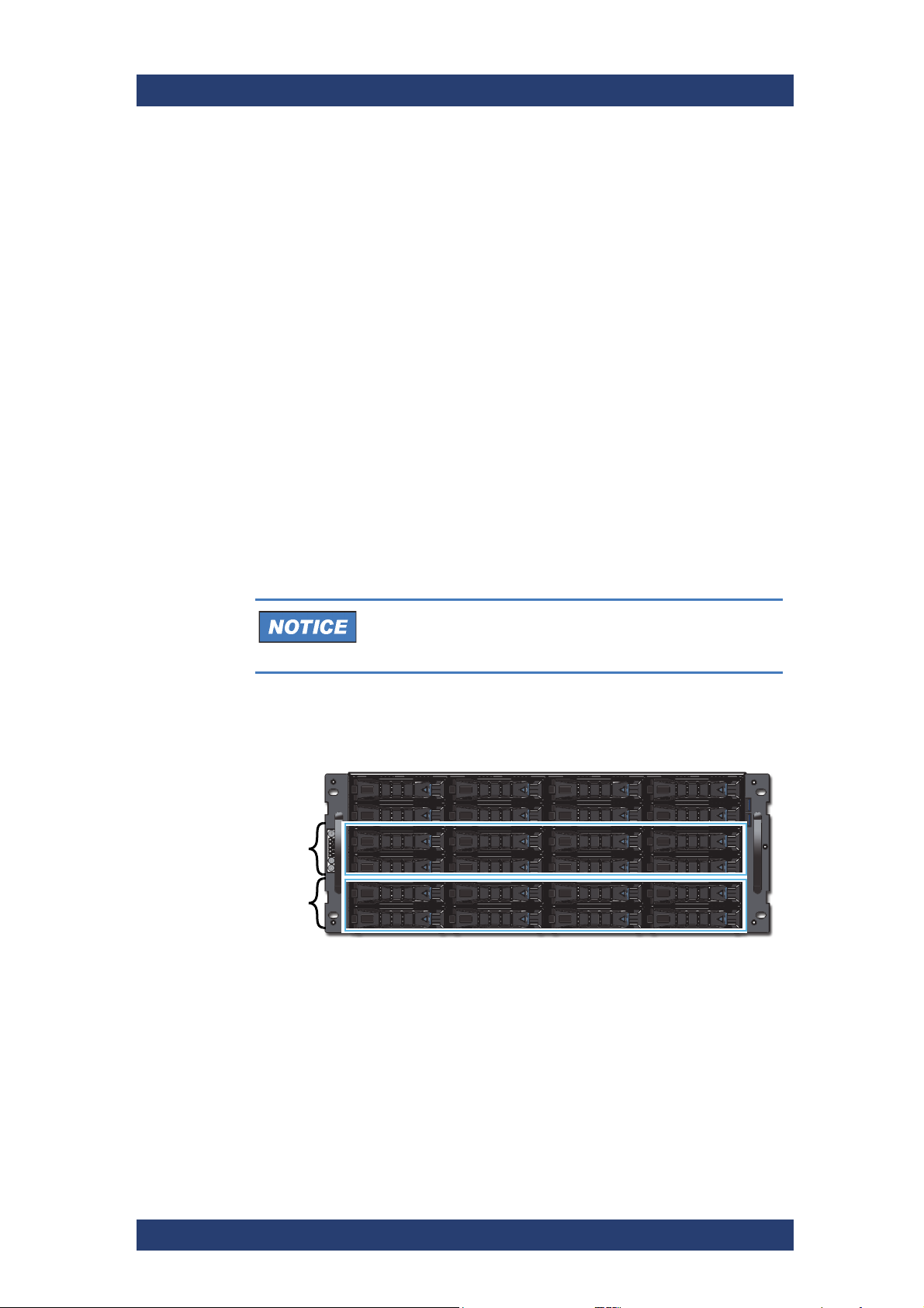
You can identify the SSD disks that are connected to a RAID controller
easily at the R&S system because every two rows represent one disk
set/RAID pack:
Disk sets (RAID packs) of the SSD disk array
With the available RAID feature the R&S system can withstand disk failures
without losing data or access to data.
User Manual (Hardware) | 2904.4460.02 - 04
45
Page 46
Maintenance
SSD Disk Maintenance
Removing the Front Cover
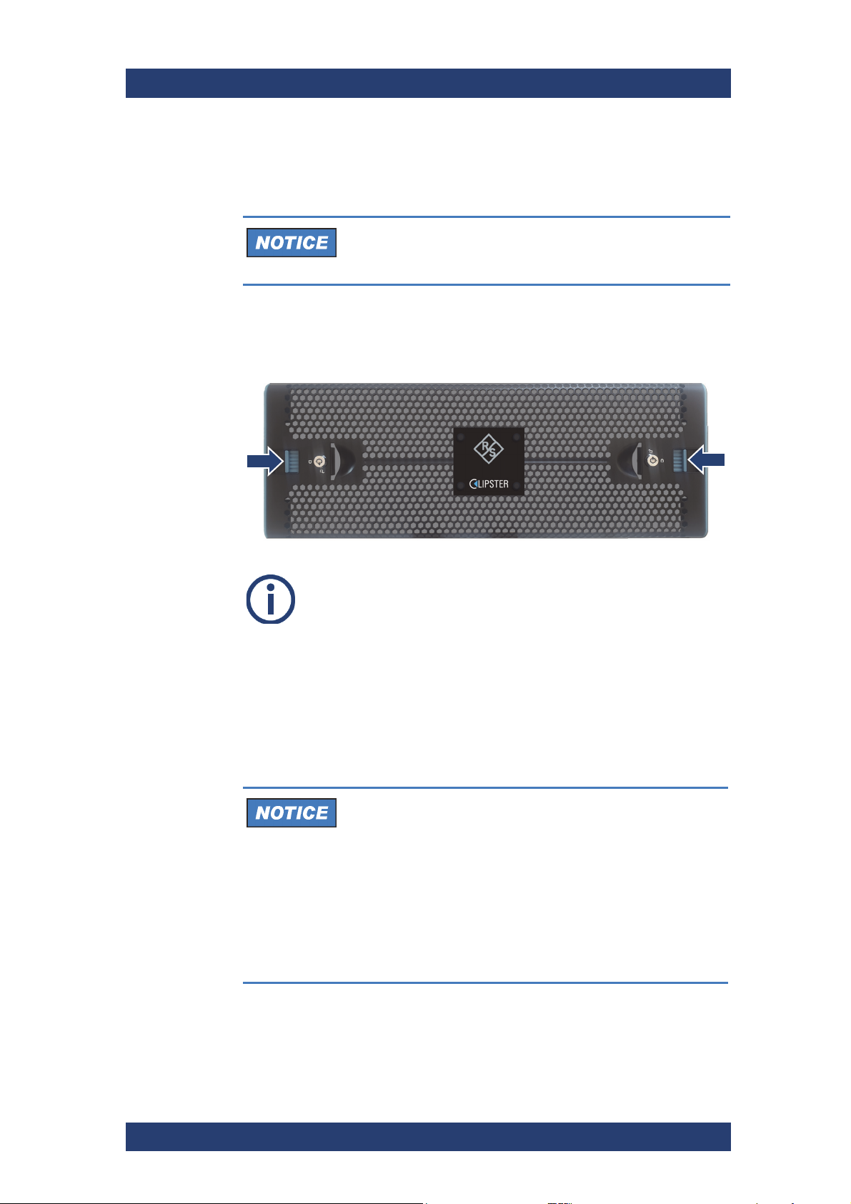
To get access to the disk arrays you will have to first remove the front cover.
Perform the following steps:
1.
2. Push both levers inwards to detach the cover and remove it.
CLIPSTER
Electromagnetic Compatibility
The system must be operated only with the front cover
closed to ensure electromagnetic compatibility.
Unlock the front cover on both sides.
To attach the front cover reverse the above steps.
The front cover is now removed.
Identifying a Defective SSD Disk
In case of an alert or when suspecting a defective SSD disk, you have to
identify the broken SSD disk first in order to replace it.
Alert
An alert can be caused by a number of reasons. Please
refer to section “Troubleshooting” on page 61 first for further
details about what to do in case of an alert.
If a SSD disk fails, the alert will be triggered by the RAID
controller. Data accesses to the SSD disk array are still
possible because any missing data will be recalculated from
the parity information stored on the other SSD disks of the
disk set. This can limit the overall performance and realtime operations may no longer be possible.
46
User Manual (Hardware) | 2904.4460.02 - 04
Page 47
CLIPSTER
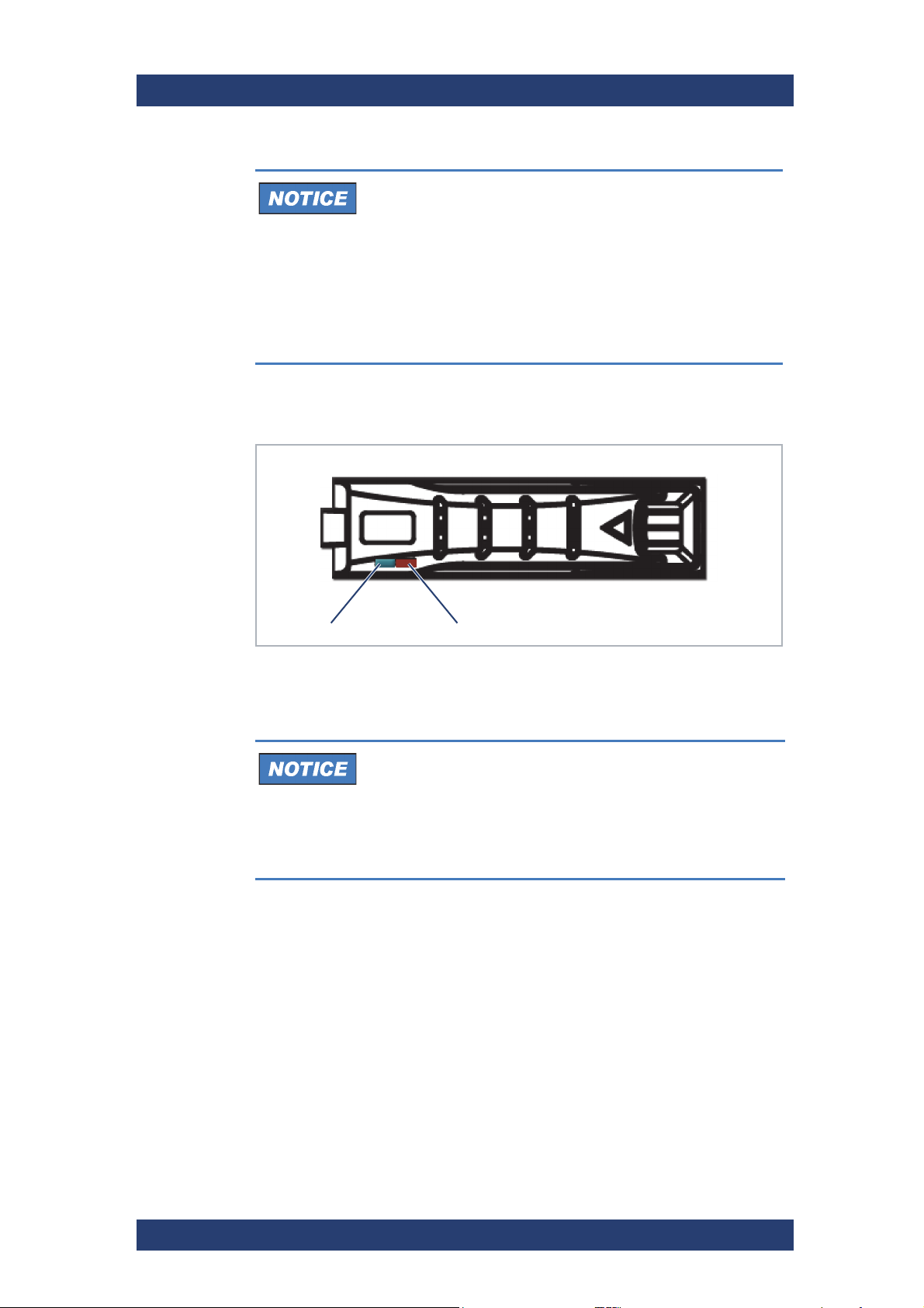
Activity LED
Error LED
Maintenance
SSD Disk Maintenance
Data Loss
If you do not replace a defective disk in time and another
disk fails in the meantime, your data may be unrecoverable.
Before replacing a SSD disk you have to gather the log
files of the RAID controller. If you do not know how to
do this, please contact the Rohde & Schwarz service
department first.
Replace the failed disk as soon as possible.
In most cases you can find the broken disk by simply observing the LEDs of
the disk array, see section “SSD Disk Array” on page 20.The status of a
single disk is indicated by two LEDs on the front of the disk carrier:
Status LEDs on Disk Drive
Once the defective disk has been identified, you can replace it as described
in section “Replacing the SSD Disk in the Carrier” on page 49.
Total Loss of Data
Replacing the wrong SSD disk, i.e. a good one instead of
the defective one, may result in a total loss of data.
If you are unsure about having detected the correct SSD
disk please contact the Rohde & Schwarz service
department.
SSD Disk Replacement
As soon as the broken SSD disk has been identified (see section “Identifying
a Defective SSD Disk” on page 46), it can be replaced easily. The replacement of a broken SSD disk can be divided into three steps:
1
Removing the SSD disk from the system.
2
Replacing the SSD disk.
3
Reassembling it into the system
User Manual (Hardware) | 2904.4460.02 - 04
47
Page 48
Maintenance
SSD Disk Maintenance
SSD Disk Removal
The SSD disks that are accessible at the front of the system are connected
to the system with the help of disk carriers. They can be removed easily,
even when the system is running (hot-swappable).
Perform the following steps:
1.
2. Remove the front cover of the system, see section “Removing the Front
CLIPSTER
Log Files
Before replacing a SSD disk you have to collect the log files
of the RAID controller. If you know how to do this you may
proceed on your own. If not, please contact the
Rohde & Schwarz service department first.
If applicable, stop all accesses to the SSD disk array of your system, for
example, by exiting the video system software and severing the network
connections.
Cover” on page 46.
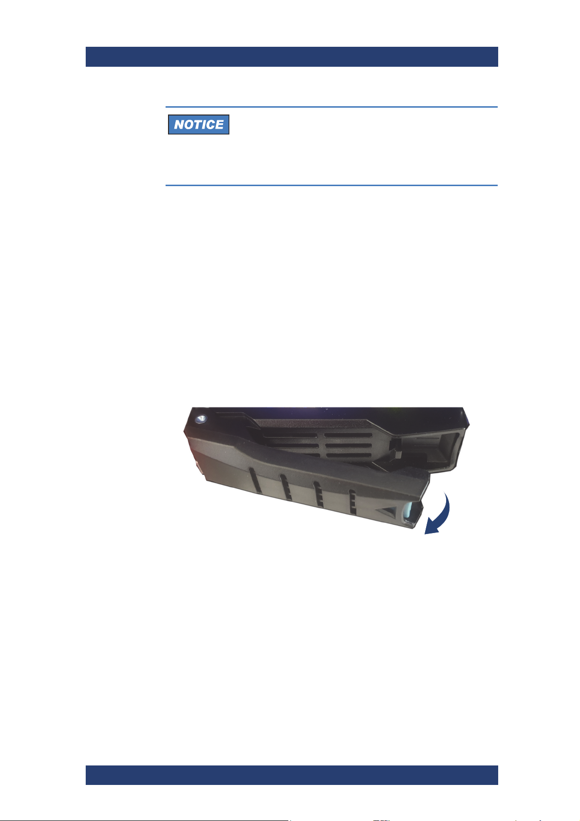
3. Unlatch the disk carrier of the defective SSD disk by pressing the release
button of the tray lever to loosen the lever.
This will cause the lever to come out of the disk carrier so that it
protrudes from the rest of the disk carriers.
48
User Manual (Hardware) | 2904.4460.02 - 04
Page 49
CLIPSTER
Maintenance
SSD Disk Maintenance
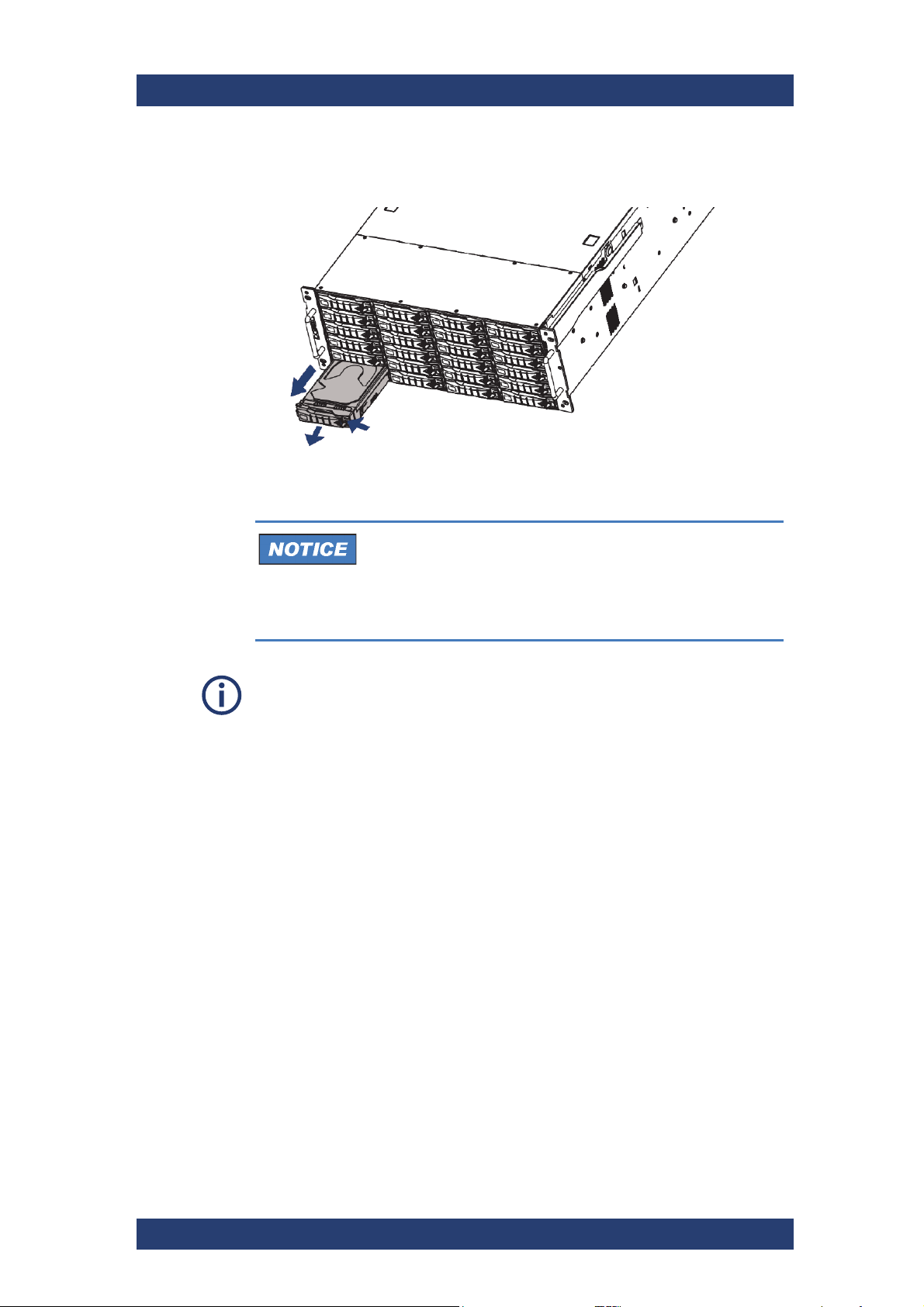
4.
Pull the tray lever outward completely and remove the disk carrier out of
the system.
Replacing the SSD Disk in the Carrier
System Damage
Significant environmental changes, for example, altitude,
voltage, temperature, shock, vibration, etc., can damage a
SSD disk.
Handle SSD disks with great care.
It is best to use the same brand and type of SSD disk again. Otherwise a loss
of performance might occur.
Perform the following steps:
1. Unscrew the screws that fix the SSD disk to the disk carrier.
2. Exchange the defective disk with a new one and assemble it in the disk
carrier with the screws.
Reassembling the SSD Disk
After replacing the SSD disk, the disk carrier with the new disk has to be
reassembled in the system.
Perform the following steps:
1. Slide the disk carrier back into its shaft at the disk array.
2. Push the disk carrier completely back into the shaft. Move it until you feel
the resistance of the SSD disk interface inside the system and until the
lever retracts.
3. Close the lever until it snaps back in place which as a result will slide the
carrier completely back in.
User Manual (Hardware) | 2904.4460.02 - 04
49
Page 50
Maintenance
Removing the Top Cover
The disk carrier of the replaced disk should be level with the others of the array.
Once the front cover of the system is back in place, the replacement of
4.
the SSD disk is finished. After several minutes the replaced SSD disk will
be automatically recognized by the system. Then the rebuild of the data
will be initiated automatically. When the system has finished the rebuild,
the system will be fully operational again.
CLIPSTER
File Access to the Disk Array
During a rebuild, real-time processing may not be possible.
It is recommended to restrict file access to the SSD disk
array until the rebuild is finished, as it takes several hours.
Avoid file access operations to the disk array during
this time, otherwise it may take considerably longer.
Removing the Top Cover
This section guides you through the process of opening the casing. This is
required e.g. in case you have to replace a defective PCI board or a cooling
fan.
High Voltage
The system you are working on operates with voltages that can be
hazardous to your health.
Do not work on the system or access its interior with the power
cables being plugged in.
Make sure the power supply is disconnected from the components you intend to work on.
System Damage
The system must be operated only with the chassis’ cover installed to
ensure proper cooling.
50
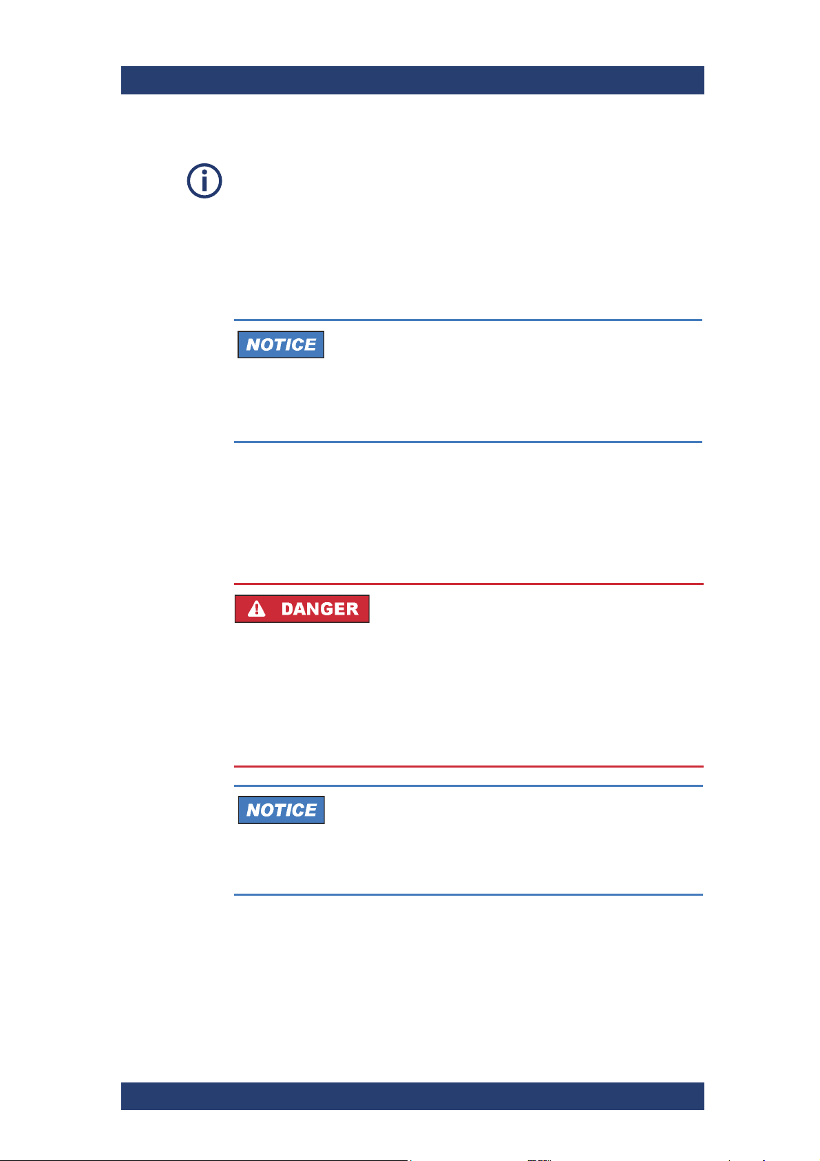
Perform the following steps:
1. Shut down the system as described in section “Shutting Down the
System” on page 41. and remove all power cords.
2. Press the release button x 2 on both sides of the chassis.
User Manual (Hardware) | 2904.4460.02 - 04
Page 51
CLIPSTER
Recovery of the System Disk
3.
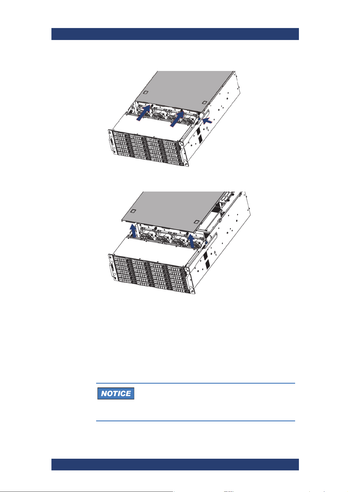
Slide the top cover towards the rear end of the system.
Once the cover is slid backward, it can be taken off the system
4. Lift the cover upwards to remove.
Maintenance
5. To close the casing, simply put the cover back on and slide it into place
until it locks.
Recovery of the System Disk
The R&S system provides a backup SSD drive (see "Overview of the Rear"
on page 21) that can be used to restore the operating system on the system
disk back to its manufacturing state. Once selected as a boot device, it will
launch a Live Linux which in turn will restore the system disk.
Total Loss of Data
Selecting the wrong device can lead to a total loss of data.
Do not execute any commands if you are not sure about
the correct target device.
User Manual (Hardware) | 2904.4460.02 - 04
51
Page 52
Maintenance
Recovery of the System Disk
Perform the following steps:
If appropriate, disconnect all Fibre Channel cables and all externally
1.
connected storage devices from the system.
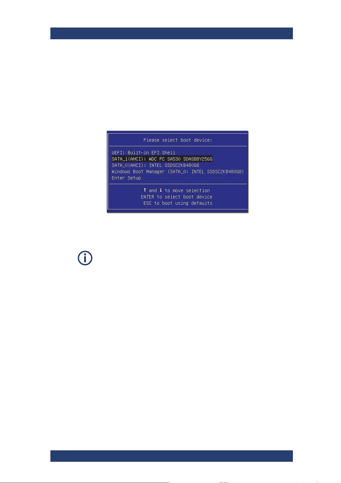
2. Turn on or restart the system and at the indicated moment during start-
up press [F11] on your keyboard to enter the boot menu.
3. Once the boot menu is displayed on the screen, select the SSD backup
drive (SATA_1 AHCI) as the boot device and then press [Enter] on your
keyboard.
CLIPSTER
The system will now boot from the backup drive and you will see a
window on the screen where you can select the R&S Rescue environment for loading.
To complete the loading of the R&S Rescue environment some user entries
are required. For this follow the instructions given on the screen.
The loading of the environment and the process itself will both try to initialize
hardware that may not be present on your system. Any error messages displayed during loading/initialization, e.g. Failed or Warning, can be disregarded. The backup/recovery process should work nonetheless.
52
User Manual (Hardware) | 2904.4460.02 - 04
Page 53
CLIPSTER
[1:0:0:0 disk ATA <device info> /dev/sda
Please enter the System-Device ( for example sda )
Recovery of the System Disk
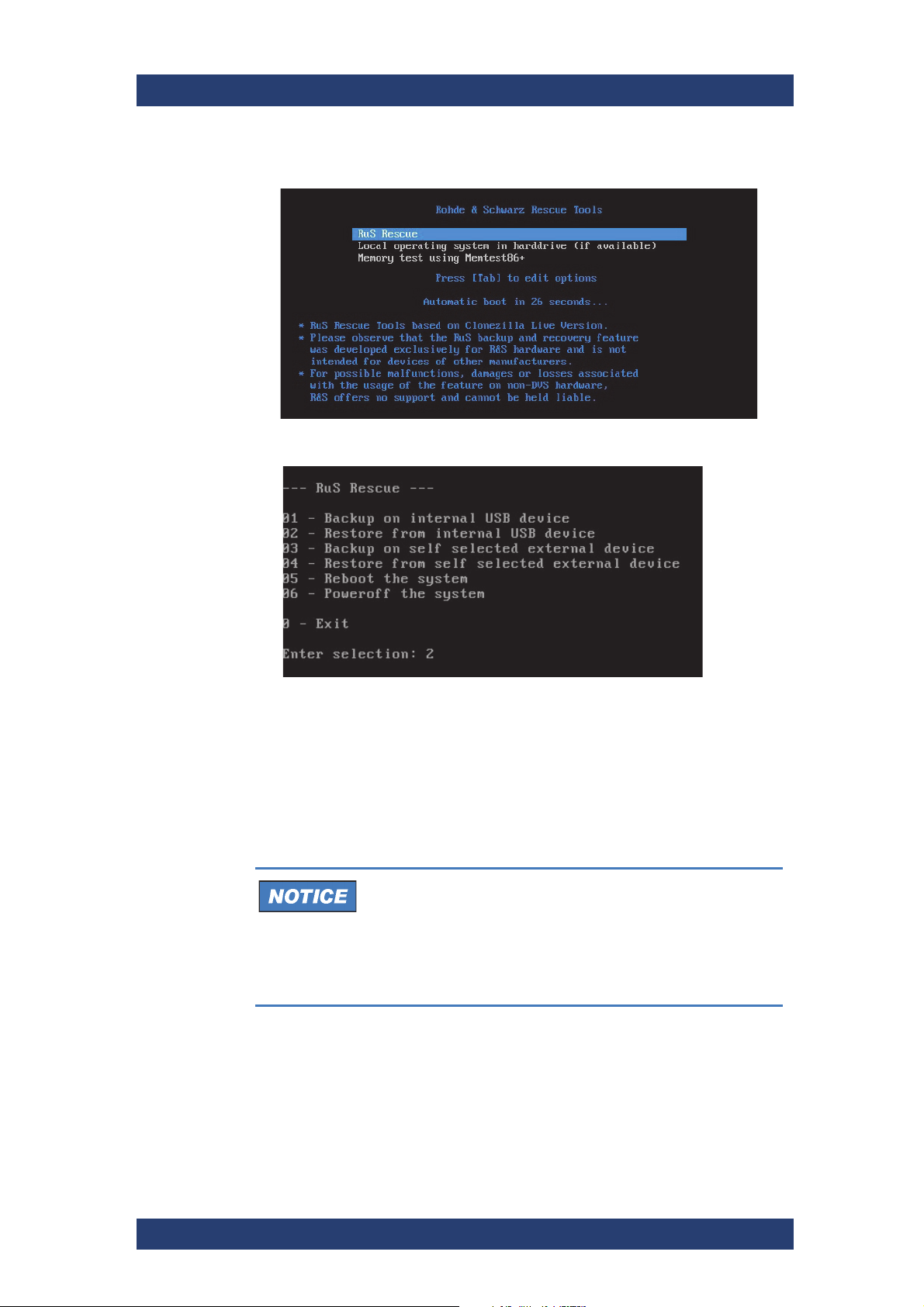
4.
Select RuS Rescue and press [Enter] on your keyboard.
Once the loading has finished, you will see the R&S Rescue menu
with its options on the screen:
Maintenance
5. To restore your system disk from the backup drive, press [2] and then
[Enter] on your keyboard.
A list of possible target devices will be detailed on the screen. The
system disk normally is the ’ATA’ disk with, for example, ’sda’, ’sdb’ or
’sdc’ as its device name:
Data Loss
The actual device name of the system disk depends on the
manufacturing process. A recovery will overwrite all your
data.
Continue with the following steps only when you are
able to identify the correct target device.
6. Enter the name of the system disk: Type in e.g. sda (or in other cases
sdb, sdc, etc.) and press [Enter] on your keyboard.
Another list will be displayed on the screen detailing the possible
source images. If there is only the recovery image on the backup
drive, this one will be listed. If there are several images, all will be
displayed.
User Manual (Hardware) | 2904.4460.02 - 04
53
Page 54

Maintenance
Recovery of the System Disk
Select the image you want to use for the recovery. Usually, it provides
7.
the serial number of the system in its name. To confirm your choice press
[Enter] on your keyboard.
The system will ask you to confirm your selection and whether you
want to continue:
8. To start the recovery process type in y for ’yes’ and press [Enter] on
your keyboard.
The program will now start the recovery process. Its progress will be
indicated on the screen.
To abort the process at this point enter n for ’no’ and press [Enter] on your
keyboard. You will be redirected to the R&S Rescue menu.
After starting the process a termination is no longer possible.
The recovery process may take some time.
If during the process the screen turns black, press [Space] to get it back
again.
CLIPSTER
When the system has finished the recovery process, you will be notified.
Then after pressing [Enter] on your keyboard, you will be redirected to the
R&S Rescue menu once more where you can choose, for example, ’reboot’
or ’poweroff’ to restart or turn off the system. The next time the system is
started, it will load the restored operating system.
54
User Manual (Hardware) | 2904.4460.02 - 04
Page 55
CLIPSTER
Maintenance
Fan Maintenance
Fan Maintenance
The system is equipped with several fans that can be exchanged in case of
a failure easily. This section describes what to do if a fan fails.
The following topics are covered:
● Preparations (page 55)
● Replacing the Fan (page 57)
Preparations
High Voltage
The system you are working on operates with voltages that can be
hazardous to your health
Never work on the system or access its interior with the power
cable(s) being plugged in.
Make sure the power supply is disconnected from the components
you intend to work on.
Maintenance inside the system should only be performed by
personnel qualified for handling and testing electrical equipment.
Electrostatic Discharge
Computer hardware contains components that are sensitive to electrostatic
discharge. If you touch them without precautionary measures, they can be
destroyed.
Avoid touching the internal components of the computer system.
User Manual (Hardware) | 2904.4460.02 - 04
55
Page 56

Maintenance
Fan Maintenance
CLIPSTER
Serious Injury
Testing the fans is possible only with an opened casing and the power
turned back on.
Once the power cables are plugged in again do not touch anything
else than the external power cords or the power switch at the front of
the system.
Under no circumstances reach inside the system.
After testing the fans switch off the power and disconnect the power
cables immediately.
Perform the following steps:
Shut down the system and unplug all power cables.
1.
2. Open the casing of the system as described in section “Removing the
Top Cover” on page 50.
3. With the casing of the system open, you can now test the fans. For this
you have to plug in the power supply again.
4. Reconnect the power cords.
5. Press the power switch to turn on the system.
6. Observe the fans and memorize the failed one (the fan not revolving is
the broken one).
7. Press the power switch until the system turns off.
8. Disconnect the power cables once again.
56
User Manual (Hardware) | 2904.4460.02 - 04
Page 57
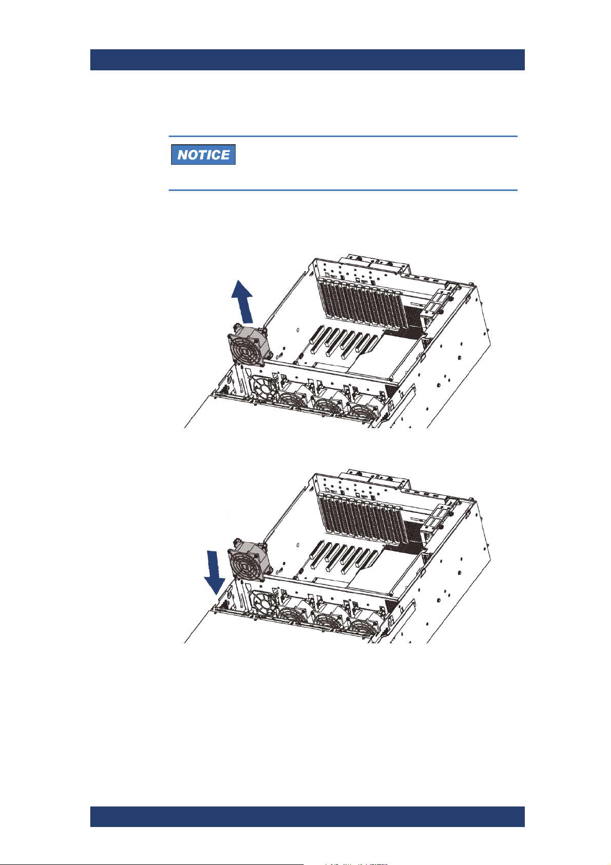
CLIPSTER
Maintenance
Fan Maintenance
Replacing the Fan
System Damage
Third-party spare parts might damage your system.
Only use original manufacturer spare parts.
Perform the following steps:
1.
Pull the fan module from the node. Pay attention to carefully dislodge the
rubber connectors from the attached bracket.
2. Insert the replacement fan into the node. Make sure to align the rubber
connectors with the appropriate slot in the bracket.
With the last step finished you have successfully replaced the defective fan
module.
User Manual (Hardware) | 2904.4460.02 - 04
57
Page 58
Maintenance
Power Supply Maintenance
Power Supply Maintenance
This section describes the maintenance of the power supply.
The following topics are covered:
● Power Supply (page 58)
● Replacing a Power Supply Unit (page 59)
Power Supply
The redundant power supply provides the system with power. It is a reliable
and enduring part of the system because it consists of several independent
power supply units: Even if one fails the other will still offer enough power to
keep the system working.
CLIPSTER
System Damage
The system can be operated with one power supply unit out
of order. However, if another one fails, a continued operation of the system cannot be guaranteed.
Change a failed power supply unit immediately.
Each power supply unit in the R&S system is hot-swappable, so you can
safely replace it with the system running, if necessary.
For an overview of a power supply unit see section “Power Supply” on
page 30.
Injury
Do not reach inside the system when removing
a power supply unit or when the unit is out of
the system.
System Damage
Third-party spare parts might damage your system.
Only use original manufacturer spare parts.
58
User Manual (Hardware) | 2904.4460.02 - 04
Page 59
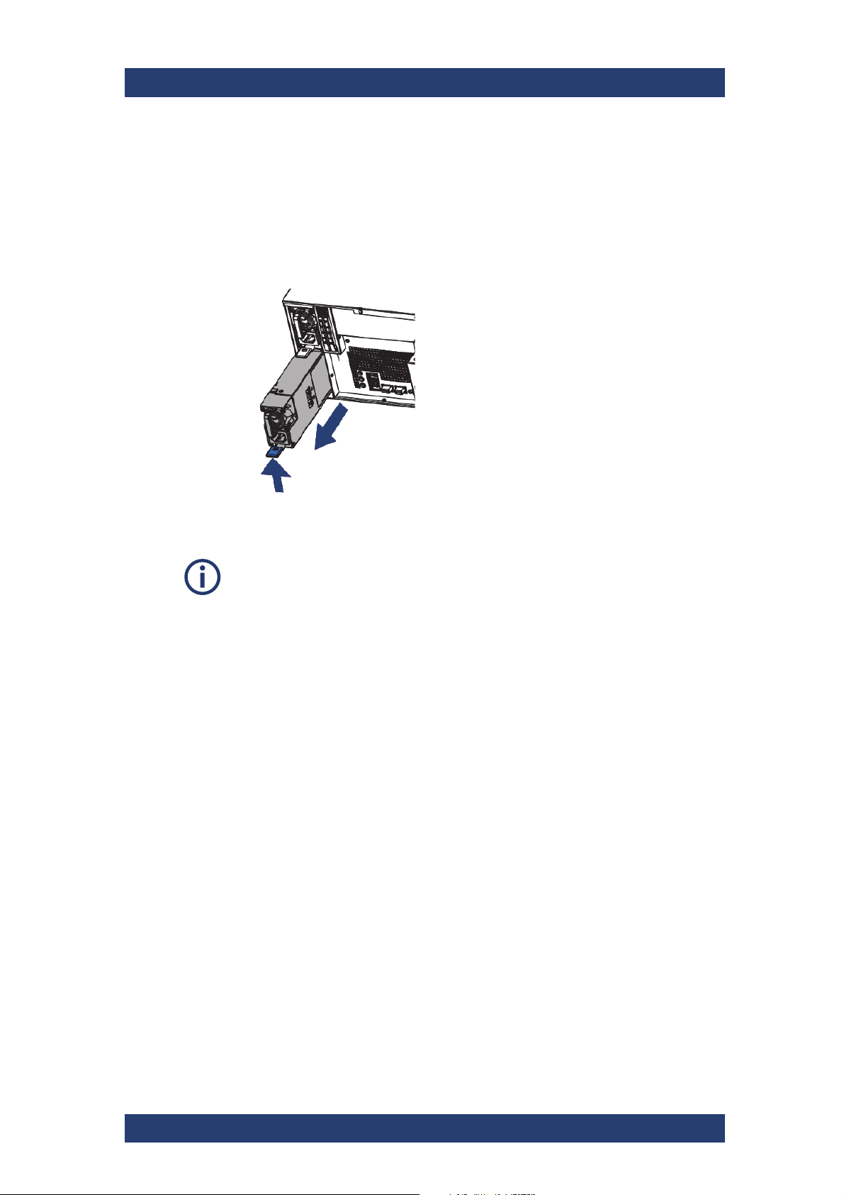
CLIPSTER
Replacing a Power Supply Unit
Perform the following steps:
1.
Unplug the power cord from this power supply unit.
2. Push the ejector to release the module.
3. Pull the handle to remove the module out of the chassis.
Maintenance
Cleaning
4. Slide the new unit into the power supply until it clicks into place.
When completely inserted please observe that the ejector latch is truly in
place and locking the unit.
5. Connect the power source (power cord) to the newly installed power
supply unit.
The power supply unit has been replaced.
Cleaning
How to clean the product is described in "Cleaning the Product" on page 10.
Do not use any liquids for cleaning. Cleaning agents, solvents (thinners,
acetone), acids and bases can damage the front panel labeling, plastic parts
and display.
Storage
Protect the product against dust. Ensure that the environmental conditions,
e.g. temperature range and climatic load, meet the values specified in the
data sheet.
User Manual (Hardware) | 2904.4460.02 - 04
59
Page 60

Maintenance
Disposal
CLIPSTER
Disposal
Rohde & Schwarz is committed to making careful, ecologically sound use of
natural resources and minimizing the environmental footprint of our products.
Help us by disposing of waste in a way that causes minimum environmental
impact.
Disposing electrical and electronic equipment
A product that is labeled as follows cannot be disposed of in normal household waste after it has come to the end of its service life. Even disposal via
the municipal collection points for waste electrical and electronic equipment
is not permitted.
Labeling in line with EU directive WEEE
Rohde & Schwarz has developed a disposal concept for the eco-friendly
disposal or recycling of waste material. Rohde & Schwarz completely fulfills
its obligation to take back and dispose of electrical and electronic waste.
Contact your local service representative to dispose of the product.
60
User Manual (Hardware) | 2904.4460.02 - 04
Page 61

CLIPSTER
Appendix
Appendix
Troubleshooting
This chapter gives some hints how to resolve irregularities during operation.
Also, technical data and general information about the R&S system are
provided.
This chapter is divided into the following sections:
● Troubleshooting (page 61)
● Technical Data (page 62)
● Packing Instructions (page 71)
Troubleshooting
The table below lists some errors that may occur during the operation of the
R&S system and details how to resolve them. If you experience trouble that
cannot be resolved with the solutions described here or in chapter "Maintenance" (page 43), please contact your local vendor or Rohde & Schwarz
directly.
Error Cause Solution
Accesses to the main
storage are slow.
AND/OR
Drops occurred during
playout/capture
The alert LED is lit. One of the power
The data storage is
too full.
Configurations of the
system have been
altered.
One or more SSD
disks of the SSD disk
array are worn.
A RAID controller is
defective.
supply units has
been disconnected
from power during
operation.
One of the power
supply units has
failed.
It is recommended to use only 85%
of the overall disk capacity to ensure
real-time capability. If the storage is
too full, delete some of your data.
Contact the Rohde & Schwarz
customer support.
Try to identify the worn disk and
replace it as described in section
“SSD Disk Maintenance” on
page 44.
If you can rule out the above
mentioned causes, a RAID controller
may be defective. Contact the
Rohde & Schwarz customer support.
Examine the power cord of the unit.
See to it that it is in good technical
order, correctly plugged in at both
ends and that the mains current is
operating properly.
Replace the broken unit as
described in section “Power Supply
Maintenance” on page 58.
A fan has failed. If necessary replace the broken
User Manual (Hardware) | 2904.4460.02 - 04
module as described in section “Fan
Maintenance” on page 55.
61
Page 62

Appendix
Technical Data
Error Cause Solution
The system is overheated.
If you can rule out the above
mentioned causes, the alert must be
due to overheating. See to it that the
ambient temperature at the front of
the system does not exceed the
operating temperature specified in
section “Technical Data” on page 62.
If the temperature is within the
range, check the ventilation holes of
the system and free them from all
obstructions (e.g. dust). In case the
problem persists, contact the
Rohde & Schwarz customer support.
CLIPSTER
An SSD disk or an
SSD disk carrier got
loose/jammed (e.g.
after transport) or is
not mounted
correctly.
An SSD disk of the
SSD disk array is
defective.
A RAID controller is
defective.
Shut down the system as described
in section “Shutting Down the
System” on page 41. Then perform
the following: Pull all disk carriers
partially out of the chassis and afterwards install them again. See to it
that they are pulled out and reassembled correctly as described in
section “Replacing the SSD Disk in
the Carrier” on page 49. After that
start the system again.
Replace the defective disk as
explained in section “Replacing the
SSD Disk in the Carrier” on page 49.
If you can rule out the above
mentioned causes, a RAID controller
may be defective. Contact the
customer support.
Technical Data
This section provides technical data of CLIPSTER.
The following topics are covered:
● General Technical Data (page 63)
● Dimensions (page 63)
● Hardware Performance Specifications (page 64)
● Signal In- and Outputs (page 67)
62
User Manual (Hardware) | 2904.4460.02 - 04
Page 63
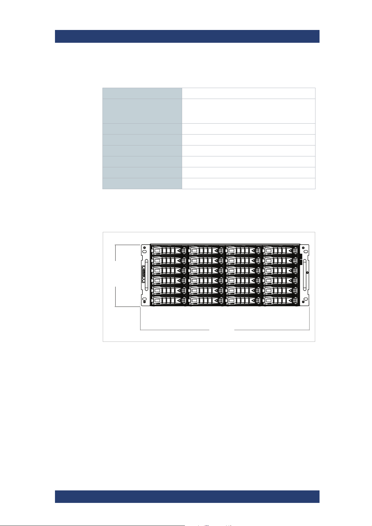
CLIPSTER
Front
43 cm
17 in
17.4 cm
6.8 in
Appendix
Technical Data
General Technical Data
Technical data
Weight approx. 45 kg
Environment (also during
transport)
Operating temperature 0ºC(32ºF) ~ 35ºC(95ºF)
Storage temperature -10ºC(14ºF) ~ 60ºC(140ºF)
Humidity 5 - 95%, non-condensing at all times
Air Dust-free
Power consumption max. 1600W (primary)
AC power 100-127V | 200~240V, 50/60Hz
No exposure to heat
No exposure to strong electric or magnetic fields
No vibrations/shocks allowed
Dimensions
The following figures show the dimensions of the system.
Dimensions of the system, front view
User Manual (Hardware) | 2904.4460.02 - 04
63
Page 64
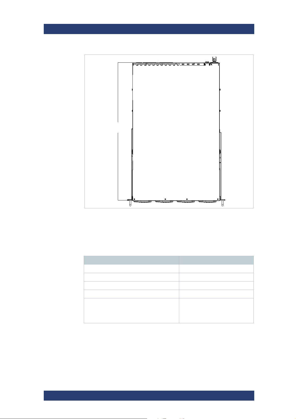
Appendix
Technical Data
CLIPSTER
68 cm
26.8 in
Dimensions of the system, top view
Hardware Performance Specifications
The following tables show the performance specifications.
J2K
Format Frames per Second
JPEG2000 Encode UHD 10 bit 60 fps
JPEG2000 Encode HD 10 bit 200 fps
JPEG2000 Playout UHD 10 bit 60 fps
JPEG2000 Playout HD 10 bit 120 fps
DPX Playout UHD 10 bit 60 fps (with processing)
120 fps (without processing, only
with CLIPSTER 4K 120p Playout
option)
64
User Manual (Hardware) | 2904.4460.02 - 04
Page 65
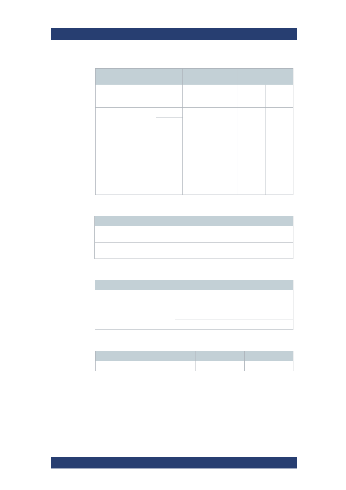
CLIPSTER
SDI supported data formats
Color Mode Bit
Depth
Rate (Hz)
Frame
Appendix
Technical Data
1.5G Link 3G Link
Monoscopic
(2D)
24 - 30 "A"
YUV 4:2:2
YUV 4:4:4
RGB 4:4:4
YUVA 4:2:2:4
YUVA 4:4:4:4
RGBA
4:4:4:4
YUV 4:2:2
YUV 4:4:4
RGB 4:4:4
Video interfaces
Video Input Output
Digital video interface via DisplayPort/HDMI
HD Serial Digital 4:2:2/4:4:4 8/10/12 bit
(Single/Dual Link, 1.5/3 Gbit/s)
10
12
48 -60
24 - 30 "A"+"B"
connector
connector
Stereoscopic
(3D)
"A"+"B"
connector
n/a
8 x BNC 8 x BNC
Monoscopic
(2D)
"A"
connector
4 x DisplayPort/HDMI
Stereoscopic
(3D)
"A"+"B"
connector
HDMI 2.0 supported data formats
Color mode Bit Depth FPS
YUV 4:2:0 8bit up to 60p
YUV 4:2:2 8, 10, 12 bit up to 60p
RGB 8bit up to 60p
10, 12 bit up to 30p
References
Reference Input Output
Analog Reference Genlock 1 BNC 1 BNC
User Manual (Hardware) | 2904.4460.02 - 04
65
Page 66

Appendix
Technical Data
CLIPSTER
Audio interfaces
Audio Input Output
Embedded Audio, 8 Digital Stereo Channels
AES/EBU, 8 Digital Stereo Channels 2 DB-25 (XLR via
Analog Audio 1 stereo head-
Timecode
Timecode Input Output
Longitudinal (LTC) 1 XLR female 1 XLR male
Data and Control Interfaces
Data and Control Interfaces Input Output
RJ-45 (RS-422 protocol) RMT-1 RMT-2
Color Modes YUV 4:2:2
Internal Processing Color volume conversion
Audio Formats 48 kHz,
2 BNC
(via Video In)
breakout cable)
YUV 4:4:4
RGB 4:4:4
YUVA 4:2:2:4
YUVA 4:4:4:4
RGBA 4:4:4:4
Encoding range conversion (Head/Full)
Frame repetition
Real-time mixer
Real-time scaler
Input raster detection
JPEG2000 compression/decompression
Optionally:
AES en- and decryption
RSA en- and decryption
Forensic Watermarking
Floating Point Processing
96 kHz (DCI and IMF only)
1 BNC
(via Video Out)
2 DB-25 (XLR via
breakout cable)
phone jacks
(6.3 mm/¼")
66
User Manual (Hardware) | 2904.4460.02 - 04
Page 67
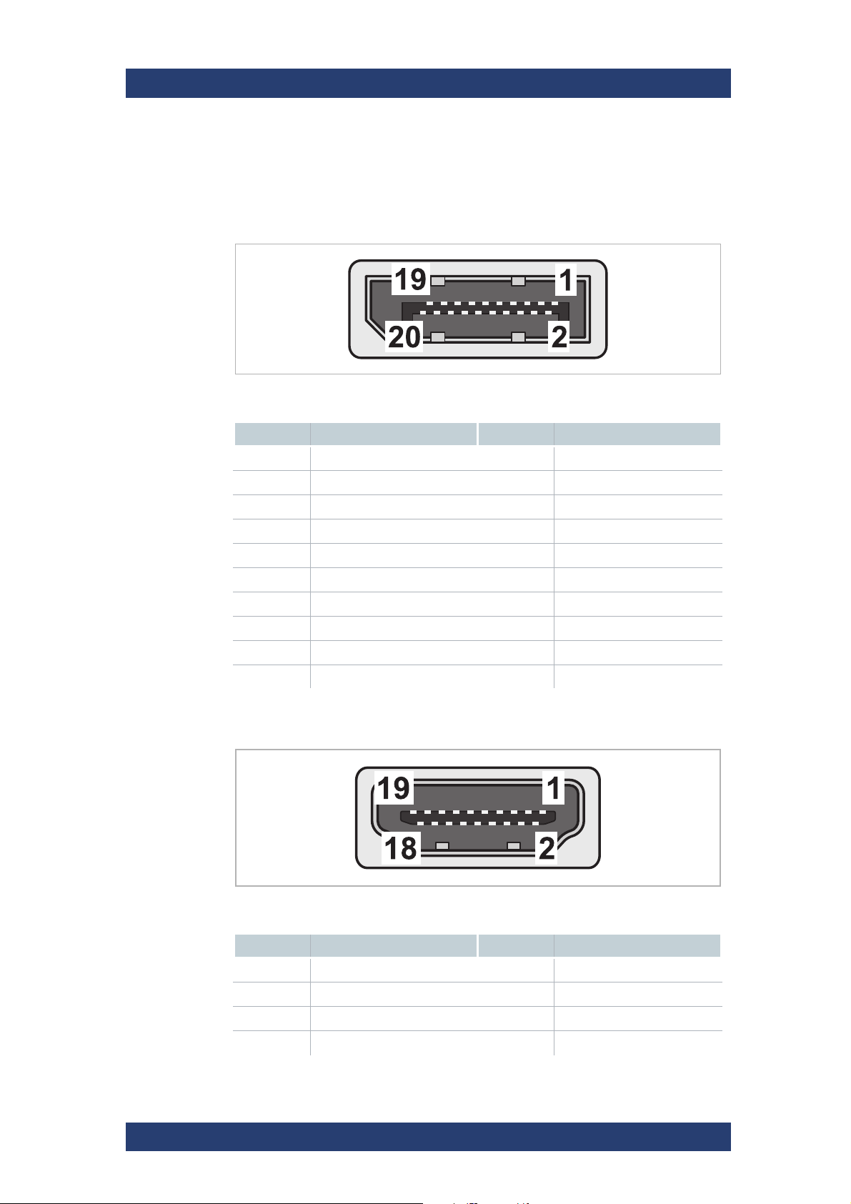
CLIPSTER
DisplayPort
Appendix
Technical Data
Signal In- and Outputs
This section provides pin-out information about some of the connectors
provided by the CLIPSTER system.
DisplayPort
Pin No. Signal Pin No. Signal
1 ML_Lane 0 (p) 11 GND
2 GND 12 ML_Lane 3 (n)
3 ML_Lane 0 (n) 13 CONFIG1
4 ML_Lane 1(p) 14 CONFIG2
5 GND 15 AUX CH (p)
6 ML_Lane 1 (n) 16 GND
7 ML_Lane 2 (p) 17 AUX CH (n)
8 GND 18 Hot Plug Detect
9 ML_Lane 2 (n) 19 Return for Power
10 ML_Lane 3(p) 20 DP_PWR
HDMI (via adapters)
HDMI port
Pin No. Signal Pin No. Signal
1 TMDS Data2+ 11 TMDS Clock Shield
2 TMDS Data2 Shield 12 TMDS Clock–
3 TMDS Data2– 13 CEC
4 TMDS Data1+ 14 Reserved (N.C. on device)
User Manual (Hardware) | 2904.4460.02 - 04
67
Page 68
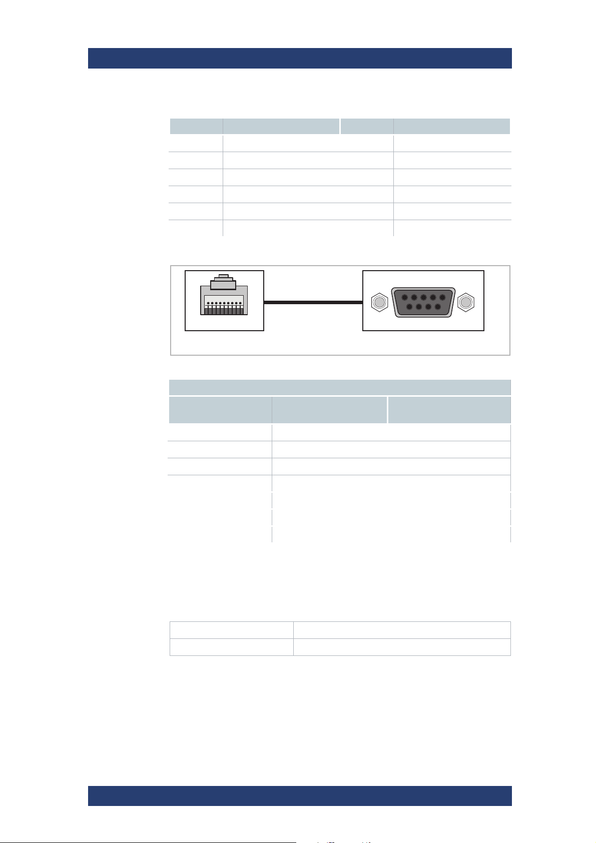
Appendix
54321
D-Sub 9RJ-45
9876
1 . . . 9
Technical Data
RMT In and
RMT Out (RJ-
45)
CLIPSTER
Pin No. Signal Pin No. Signal
5 TMDS Data1 Shield 15 SCL
6 TMDS Data1– 16 SDA
7 TMDS Data0+ 17 DDC/CEC Ground
8 TMDS Data0 Shield 18 +5 V Power (max 50 mA)
9 TMDS Data0– 19 Hot Plug Detect
10 TMDS Clock+
Analog Audio
(6.3 mm (¼")
Headphone
Jack)
RS-422 (RJ-45 [RIB7.0] male to D-Sub 9 female, external view)
Output
RJ-45
Pin No.
3 TX (+) 3
6 TX (-) 8
5 RX (+) 7
4 RX (-) 2
1 Ground 4, 6
2 Reserved 5
7, 8 not connected 1, 9
Signal D-Sub 9
Pin No.
For RS-422 control R&S systems support the standard industrial 9-pin
protocol.
Analog Audio
Output Impedance 75 Ohm
Output Level 1.55 V (at 600 Ohm)
68
User Manual (Hardware) | 2904.4460.02 - 04
Page 69
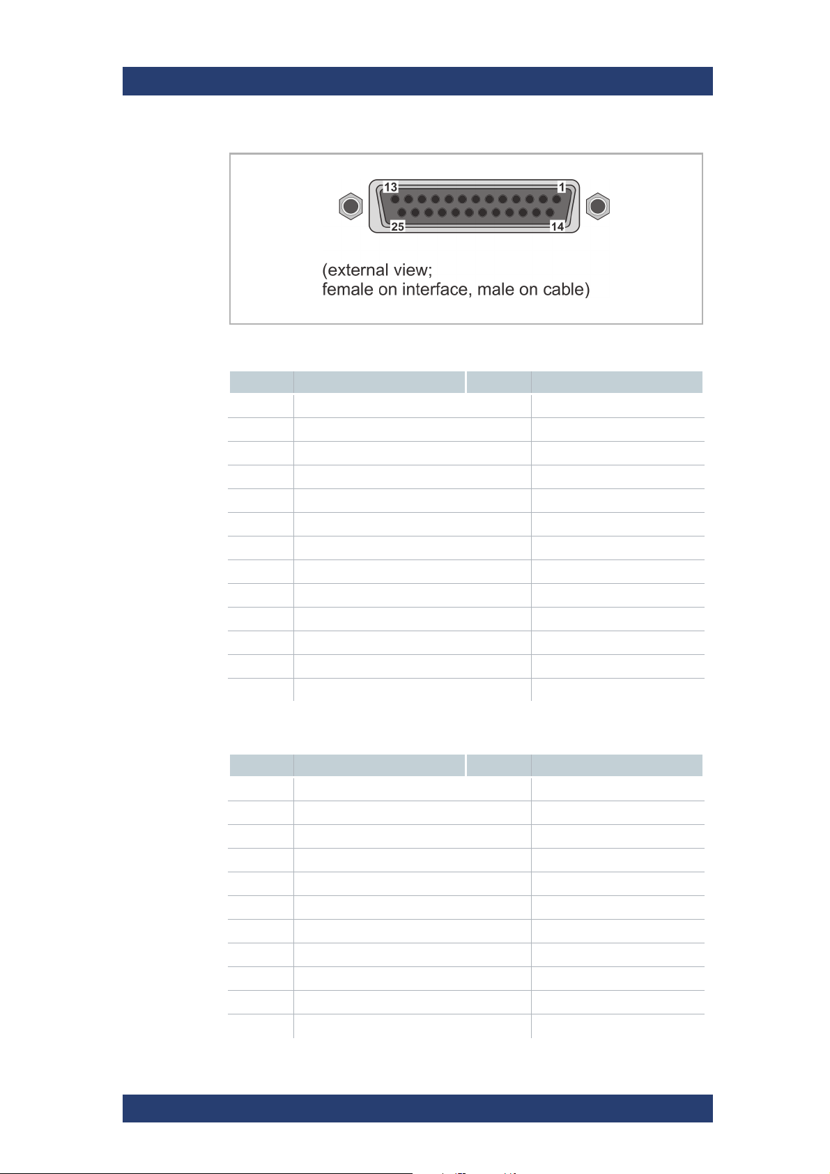
CLIPSTER
Digital Audio
(25-Pin D-Sub
Connector)
Appendix
Technical Data
External view: female on interface, male on cable
Digital Audio Ch. 1-8
Pin No. Signal Pin No. Signal
1 Audio OUT CH 7/8 14 /Audio OUT CH 7/8
2 GND 15 Audio OUT CH 5/6
3 /Audio OUT CH 5/6 16 GND
4 Audio OUT CH 3/4 17 /Audio OUT CH 3/4
5 GND 18 Audio OUT CH 1/2
6 /Audio OUT CH 1/2 19 GND
7 Audio IN CH 7/8 20 /Audio IN CH 7/8
8 GND 21 Audio IN CH 5/6
9 /Audio IN CH 5/6 22 GND
10 Audio IN CH 3/4 23 /Audio IN CH 3/4
11 GND 24 Audio IN CH 1/2
12 /Audio IN CH 1/2 25 GND
13 –
Digital Audio Ch. 9-16
Pin No. Signal Pin No. Signal
1 Audio OUT CH 15/16 14 /Audio OUT CH 15/16
2 GND 15 Audio OUT CH 13/14
3 /Audio OUT CH 13/14 16 GND
4 Audio OUT CH 11/12 17 /Audio OUT CH 11/12
5 GND 18 Audio OUT CH 9/10
6 /Audio OUT CH 9/10 19 GND
7 Audio IN CH 15/16 20 /Audio IN CH 15/16
8 GND 21 Audio IN CH 13/14
9 /Audio IN CH 13/14 22 GND
10 Audio IN CH 11/12 23 /Audio IN CH 11/12
11 GND 24 Audio IN CH 9/10
User Manual (Hardware) | 2904.4460.02 - 04
69
Page 70

Appendix
Technical Data
CLIPSTER
Digital Audio Ch. 9-16 (Forts.)
Pin No. Signal Pin No. Signal
12 /Audio IN CH 9/10 25 GND
13 –
70
User Manual (Hardware) | 2904.4460.02 - 04
Page 71
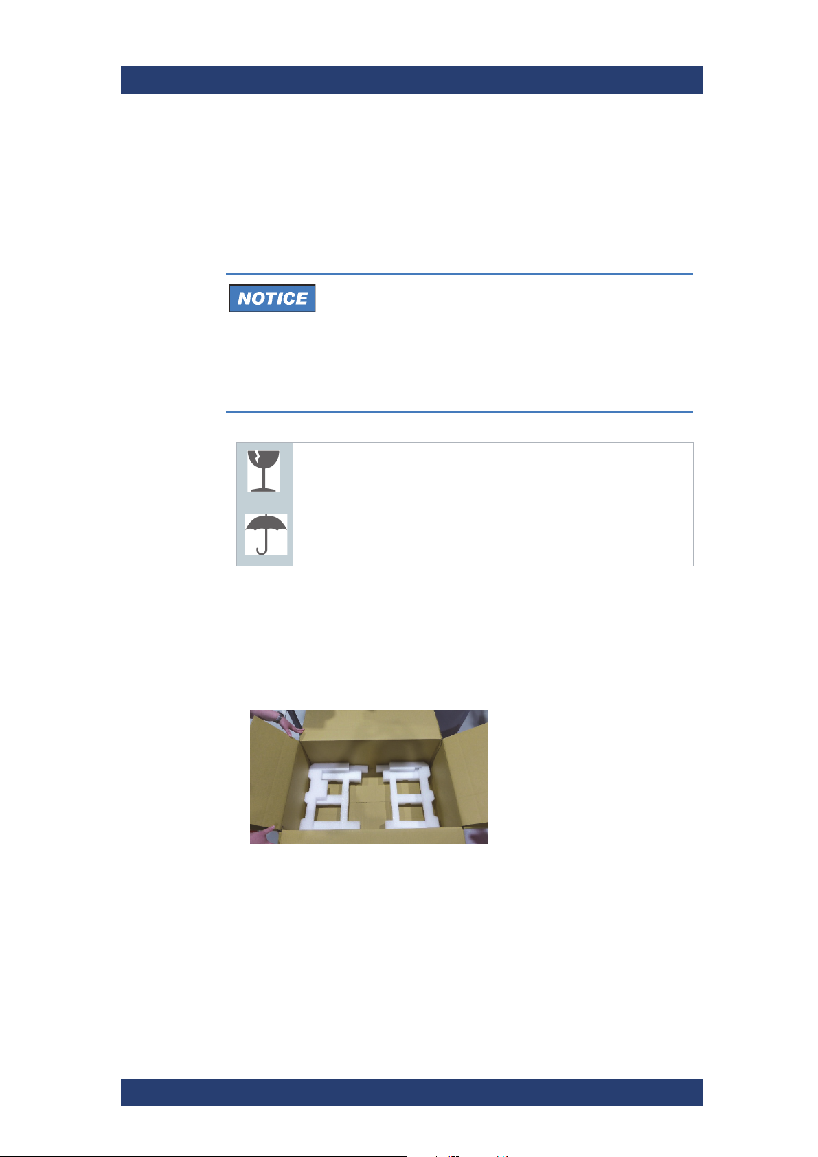
CLIPSTER
Appendix
Packing Instructions
Packing Instructions
The following describes the best way to pack a R&S system.
Safety
Transportation Damage
If you do not have the original packing anymore, use a
similar structured packing for transportation.
Rohde & Schwarz cannot be held liable for transportation
damages.
Keep the original packing and use it in case of transportation. Otherwise the warranty will be void.
Fragile. Avoid shocks or vibrations. For longer distances use a lifting
device.
Keep dry.
Packing the System
Perform the following steps:
1. Prepare the original box by placing the left and right padding foams at
the bottom.
User Manual (Hardware) | 2904.4460.02 - 04
71
Page 72
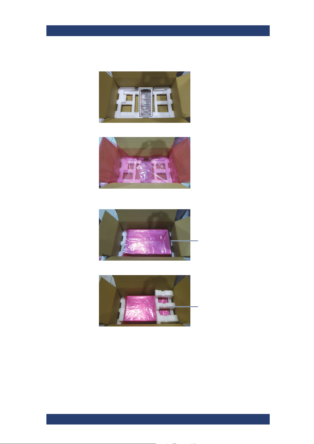
Appendix
front
front foam
Packing Instructions
2.
3. Place ESD foil on top of the front cover and the bottom foams.
CLIPSTER
Wrap the front cover in bubble foil and place it in the middle between the
two foams.
4. Place the system into the box with the front pointing to the right and wrap
it completely with the ESD foil.
5. Place the front foam at the front of the system.
72
User Manual (Hardware) | 2904.4460.02 - 04
Page 73
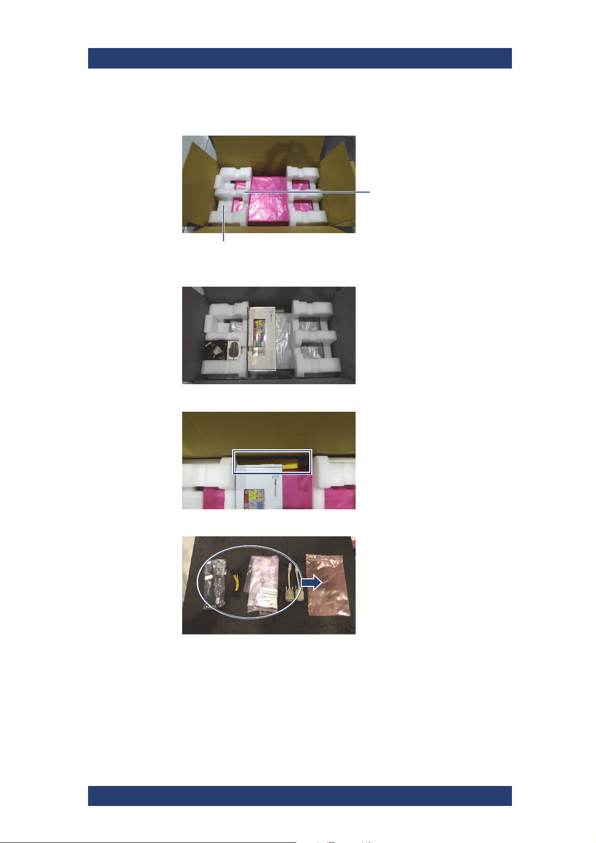
CLIPSTER
back foam
smaller padding foam
Appendix
Packing Instructions
6.
Place the smaller padding foam and the back foam to secure the back of
the system.
7. Place the power cable, mouse and keyboard as shown below.
8. Place any storage drives accessories as shown below.
9. Put the data cables into an ESD bag.
User Manual (Hardware) | 2904.4460.02 - 04
73
Page 74
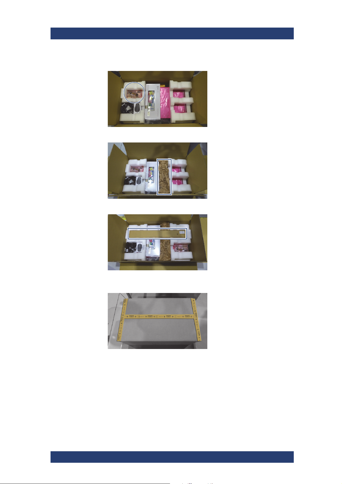
Appendix
Packing Instructions
10.
11. Place some crumbled paper between the keyboard and the front foam.
CLIPSTER
Place the ESD bag with the data cables as shown below.
12. Pack all remaining accessories in a box and place it as shown below.
13. Close the box, seal it with adhesive tape and place the entire box on a
pallet.
74
User Manual (Hardware) | 2904.4460.02 - 04
Page 75
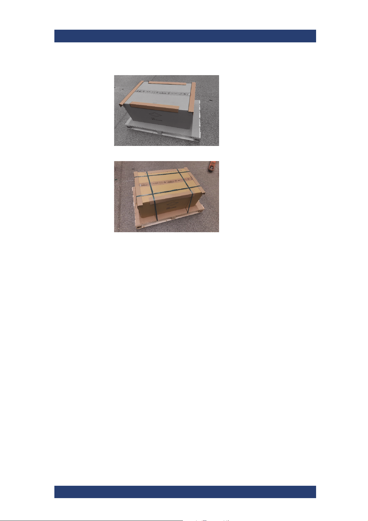
CLIPSTER
14.
Place the edge protectors at each side of the top surface.
15. Secure the box to the pallet as shown.
Appendix
Packing Instructions
The system is packed and ready for transportation.
User Manual (Hardware) | 2904.4460.02 - 04
75
Page 76

Appendix
Packing Instructions
CLIPSTER
76
User Manual (Hardware) | 2904.4460.02 - 04
Page 77

Index
IndexCLIPSTER
Numerisch
25-pin D-Sub connector pin-out ............69
A
alarm
disk failure
overheating
RAID controller
Analog Audio Out
Mon. 1
specifications
appropriate use .........................................7
atx panel ..................................................27
audio
analog audio
digital (AES/EBU)
pin-out
..........................................46
.........................................62
....................................46
.................................................23
......................................68
................................. 23, 68
.................................23
.................................................69
C
CE .............................................................14
CLIPSTER
specifications
technical data
color modes ............................................25
composite sync ......................................23
connectors
DisplayPort
HDMI
...................................................29
main connector panel
naming conventions
slot panels
conventions
naming of connectors
......................................64
......................................62
..........................................29
..........................23
............................24
...........................................28
..........................24
E
environmental conditions ......................63
exchanging
fan
.......................................................55
power supply unit
SSD disk
.............................................47
......................... 58, 59
F
fan failure ................................................55
FCC ..........................................................15
front overview .........................................17
front plate
lifting
...................................................46
G
graphics card ..........................................30
H
hardware
variants
HDMI connector ......................................29
HD-SDI .....................................................23
horizontal sync .......................................23
...............................................64
I
important notes ......................................31
installation ...............................................38
instructions
packing
intended use .............................................7
IPMI ..........................................................42
...............................................71
D
data protection ........................................45
DB-25 connector .....................................69
Digital Audio
Ch. 1-8
Ch. 9-16
digital video .............................................29
dimensions ..............................................63
disk(s)
failure
Display Port .............................................67
DisplayPort connector ...........................29
Documentation .........................................5
downconvert ...........................................23
dual link ...................................................29
User Manual (Hardware) | 2904.4460.02 - 04
.......................................... 23, 69
...............................................23
..................................................44
L
lifting the front palte ...............................46
LTC
In
.........................................................23
Out
......................................................23
M
main connector panel ............................23
maintenance ............................................43
N
naming conventions (connectors) ........24
77
Page 78

Index CLIPSTER
notes (important) ....................................31
O
operation items .......................................19
overheating .............................................62
overview
front
....................................................17
rear
.....................................................21
P
packing instructions ..............................71
pin-out
25-pin D-Sub connector
audio
...................................................69
power supply
replacing
unit failure
.............................................59
...........................................58
.......................69
R
RAID .........................................................45
rear overview ..........................................21
REF In ......................................................23
reference input ........................................23
replacing a SSD disk ..............................47
Required reading ......................................5
RJ-45 ........................................................23
RS422 .......................................................23
T
target audience .........................................7
technical data ..........................................62
dimensions
general
troubleshooting ......................................61
.........................................63
................................................63
U
unpacking ................................................33
V
variants ....................................................64
video I/O panel ........................................29
video workstation ...................................17
S
Safety
Maintenance
safety .........................................................7
SDI (serial digital interface)
signal distribution
SDI downconvert ....................................23
shut down ................................................41
shutting down .........................................41
signal distribution (SDI) .........................25
single link ................................................29
slot panel connectors ............................28
specification(s) .......................................64
analog audio
SSD ..........................................................44
SSD disk(s) ..............................................20
removal
replace
start ..........................................................39
starting ....................................................39
........................................43
...............................25
........................................68
...............................................48
......................................... 47, 49
78
User Manual (Hardware) | 2904.4460.02 - 04
 Loading...