

Page 1

ICS Regent
®
PD-6013
AC Digital Input Module
110 VAC
(T3404)
Issue 1,
The AC digital input module provides input sensing for 16
field input switches. One type of module is available for
interfacing to inputs powered from 110 VAC field power
supplies. The module's triplicated I/O Safetybus interface
ensures that no failure in the module can affect the operation
of the Regent system or other I/O modules in the system.
Extensive fault detection and annunciation of critical
redundant circuits help prevent the controllers from receiving
erroneous data from a faulty input module.
March, 06
Features
·
Sixteen input circuits, configured as two isolated groups of
eight circuits each.
·
Fault tole
redundant modules of the same type.
·
Hot-replaceable.
·
Automatic self-testing of triplicated I/O Safetybus circuits and
many simplex logic circuits.
·
Individual front panel indicators on each module show active
and fault status and logic-side input on/off status.
·
2500 volt minimum electrical isolation between field and logic
circu
·
TÜV certified, Risk Class 5.
Three AC digital input modules can be connected in parallel
to obtain fault tolerant input sensing. In this triple module
configuration, a failed module can be removed and replaced
without interrupting the input signals.
rant operation when connected in parallel with
its.
Industrial Control Services
1
Page 2
AC Digital Input Module
(T3404)
Module Operation
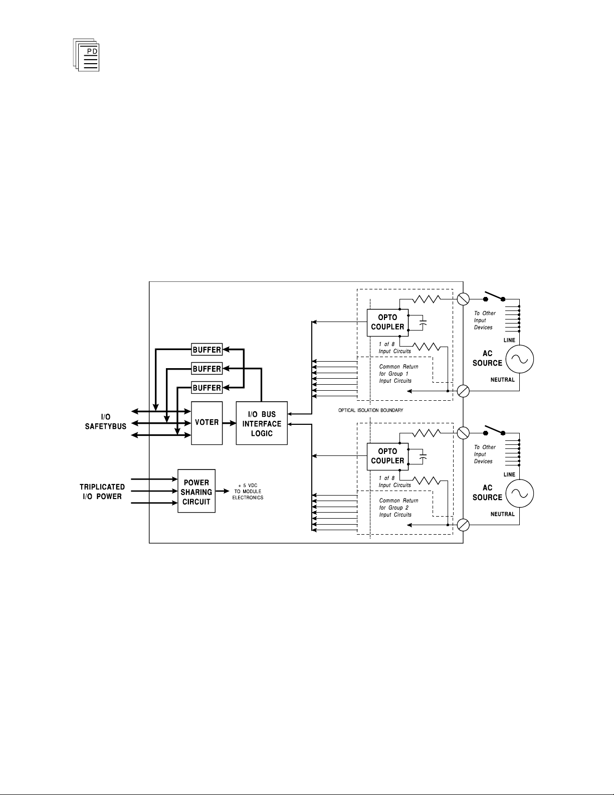
A block diagram of an AC digital input module is shown in
Figure 1.
Optical isolation between field wiring and the module’s logic
circuitry provides field-to-logic isolation —
module’s logic circuits from field signal over-voltages,
transients, and other electrical disturbances. It also provides
a safety barrier between the primary field voltages and user
accessible circuits.
pr
otecting the
2
Figure 1. Block Diagram of AC Digital Input Module.
When the field switch is closed, the input to the module is on.
When the field switch opens, the input to the module turns off.
Data from the logic side of the optical isolators are bused to
the I/O bus interface logic.
The processor modules send triplicated read data requests to
the input module over the I/O Safetybus. The processors’
addressing data and data read requests are voted by the
Industrial Control Services
Page 3

(T3404)
module (preventing I/O Safetybus failures upstream from the
module from affecting its ability to be read). The voted result
is then passed to the I/O bus interface logic.
After receiving the voted data read request, the I/O bus
interface logic sends its input data to the module’s three bus
drivers. Each o
powered and controlled by the I/O transceiver modules—
preventing failures in a single driver from propagating to the
other two busses.
The bus drivers transmit the data across the backplane I/O
Safetybus to the I/O transceivers which, in turn, transmit the
data to the processors.
f the three bus drivers is independently
AC Digital Input Module
Testing and Diagnostics
Each module’s voter circuits are periodically tested by the
processor modules. Discrepant data are sent through one of
three legs of the I/O Safetybus to determine
module’s voter is able to outvote the incorrect data. A failure
to return the correct majority-voted result to the processors
produces an I/O module error indication at the processor
modules and a module fault indication at the I/O module.
Each type of module has a unique identification code that is
read by the controller. This code lets the controller know
which type of module is installed in each I/O chassis slot and
how to address that module and its points specifically. If a
module is rem
type, the processor modules will indicate I/O module errors.
Loopback logic tests periodically write data to the module and
then read it back to determine whether the module’s I/O bus
interface logic is functioning correctly.
oved, or is replaced with a module of a different
Front Panel Indicators
whether the
PD-6013
Mar-06
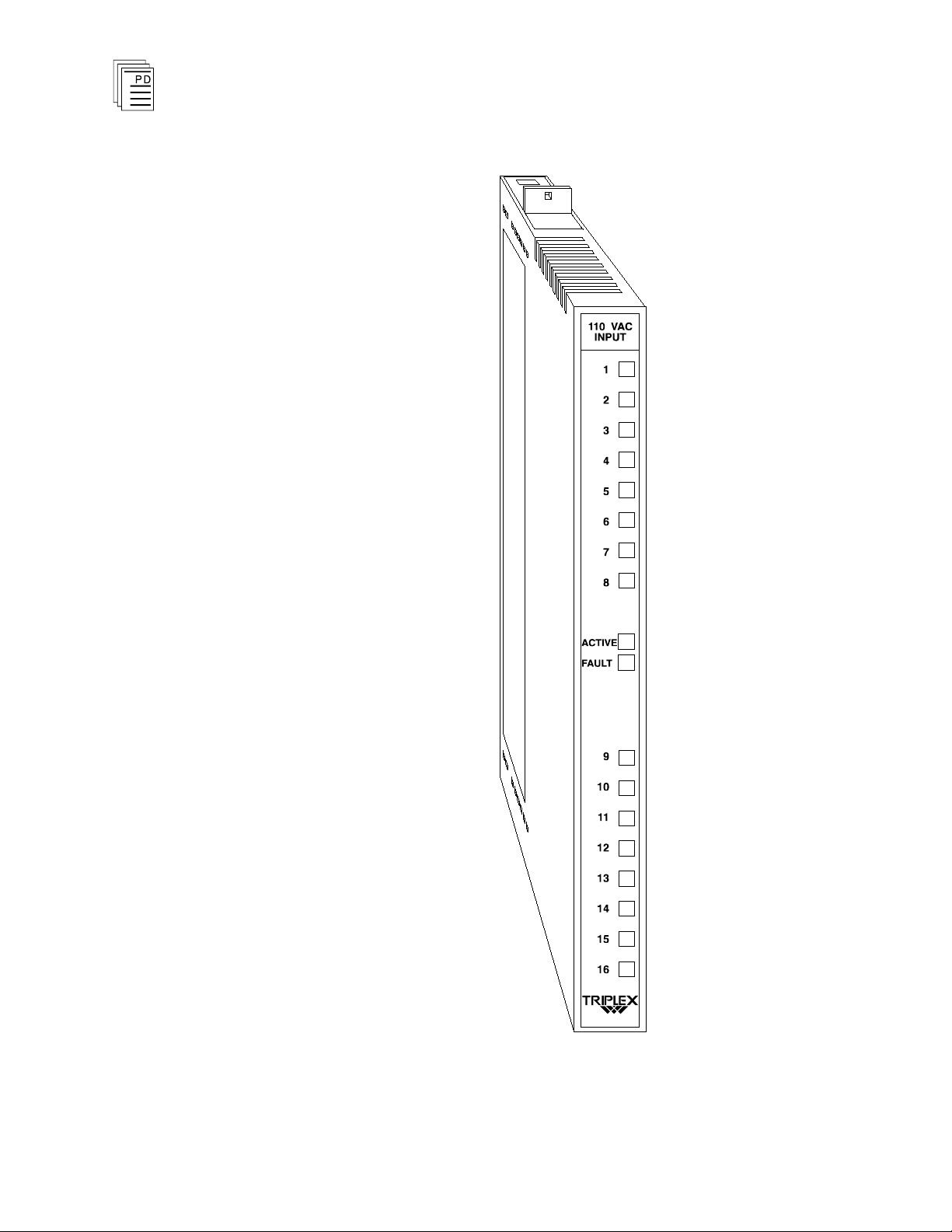
Figure 2 shows the physical features of the AC digital input
module. The front panel of each module contains active and
fault status indicators and field signal status indicators
each circuit.
3
for
Page 4
AC Digital Input Module
(T3404)
4
Figure 2. AC Digital Input Module.
Industrial Control Services
Page 5
(T3404)
AC Digital Input Module
Application
Active and Fault Status Indicators
These green and red LEDs indicate the overall health of the
module. During normal operation the green ACTIVE
indicator flashes at the controller's scan rate. If a module
fault is detected the red FAULT indicator turns on and the
green indicator turns off.
Field Status Indicators
Input status indicators are located on the logic-side (after the
signal conditioning and isolation). The field status indicators
are lit when current is flowing through the input.
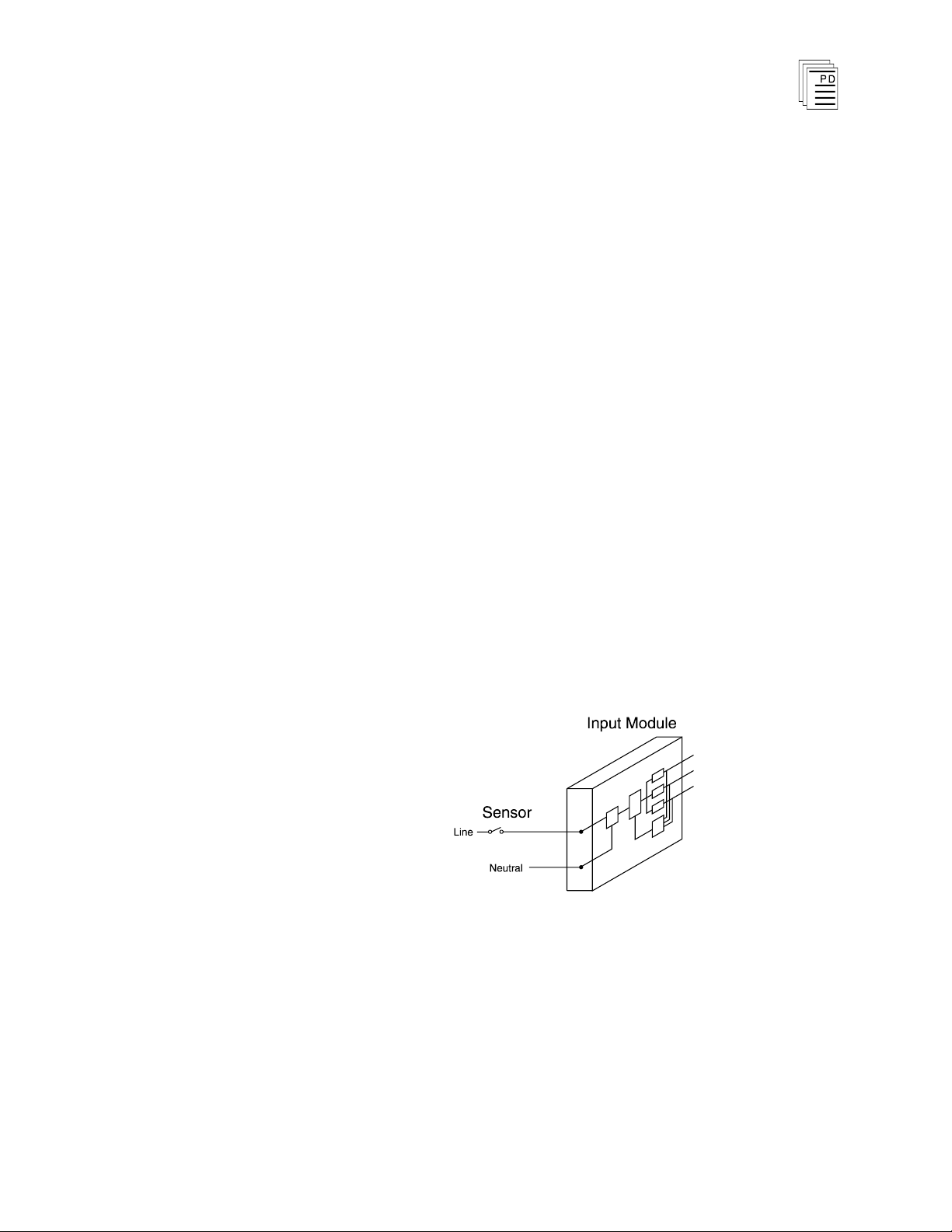
Simplex Configuration
Digital input modules provide a suitable interface to non
critical input signals. Although many of the circuits in the
digital input modules are automatically tested and
annunciated, some logic circuits and all of the field-side
sensing circuits are simplex and non-tested. This simplex
input configuration is illustrated in Figure 3.
-
PD-6013
Mar-06
Figure 3. Simplex Digital Input Configuration.
Fault Tolerant Connection
For critical inputs, redundant input modules are used in a
2oo3 or 1oo2 fault tolerant configuration. In these
configurations the redundant input modules are connected to
single or multiple sensors. If redundant sensors are installed
5
Page 6

AC Digital Input Module
in the field, the redundant modules are connected so that each
sensor connects to one of the redundant modules. These
configurations are illustrated in Figure 4, showing triple
redundant input modules. Each AC digital input module is
hot replaceable. In triple redundant input configurations, if a
fault occurs on one module, it can be removed and replaced
while the system continues to sense the inputs from the
remaining two input modules.
(T3404)
Figure 4. Fault Tolerant Digital Input Configurations.
Field Wiring
6
Field wiring terminal blocks on the I/O chassis are used to
c
onnect the field input signals and the common power return
signals to the module. The terminal blocks are located
directly above and below the slot where the module is
Industrial Control Services
Page 7

(T3404)
AC Digital Input Module
installed. Each terminal block consists of ten #6 wire clamp
screw terminals, with each terminal capable of holding two 12
AWG wires.
The module has a separate common power return terminal for
each group of inputs (group 1: channels 1-8, group 2: channels
9-16). These two groups are electrically isolated from each
other (2500 volts minimum
connection of input signals to the input wiring terminals.
). Figure 5 shows the proper
When redundant field sensors are installed, each input
module is wired as shown in Figure 5. In a fault tolerant
configuration with single field sensors, the input signals are
connected in parallel across all three input modules as shown
in Figure 6.
PD-6013
Mar-06
7
Page 8

AC Digital Input Module
(T3404)
8
Figure 5. Module Wiring, Sin
Input Module.
gle Sensors to a Single Digital
Industrial Control Services
Page 9

(T3404)
AC Digital Input Module
PD-6013
Mar-06
Figure 6. Module Wiring, Single Sensors to Triplicated
Digital Input Modules.
9
Page 10

AC Digital Input Module
(T3404)
Keying
The I/O chassis can be physically keyed to prevent accidental
damage caused by inserting a module into a slot wired for a
different module type. Figure 7 illustrates how the slot keys
are installed on the I/O chassis slot field wiring connectors.
The slot key positions for the AC digital input module are
listed in Table 1.
10
Figure 7. Installing Slot Keys.
Industrial Control Services
Page 11

(T3404)
Module
Upper
Connector
Lower
Connector
T3404
17 15
AC Digital Input Module
Table 1. Slot Key Positions.
Configuration
Each input module is configured using the
W
INTERPRET
I/O
Configuration Editor. In the editor, you will perform the
three steps described below to configure the input module.
1) Set the Module Type:
Position the cursor on the module slot you wish to define.
Choose Set Module Type from the Edit M
the appropriate digital input module from the list.
2) Edit the Module Definition:
enu and select
Choose Edit Module Definition from the Edit Menu. A
dialog box will open where you can define the input point
definitions.
PD-6013
Mar-06
Figure 8. Digital Input Module Definition.
3) Edit each point:
Choose Edit from the Module Definition dialog box to
define a name and description for each I/O point. In the
11
Page 12

AC Digital Input Module
Digital Input Point dialog, enter a tag name (up to 12
characters) and a description (up to 40 cha
(T3404)
racters).
Figure 9. Defining a Digital Input Point.
The tag names are used in the application program to
represent the input state. In addition, a module tag name can
be entered to represent the combined state of all 16 inputs.
This module tag name represents the 16 inputs as a signed,
16-bit integer. In this format, input point one is the least
significant bit (LSB) and input point 16 is the most significant
bit (MSB).
Programming
Inputs are referenced in the application program through the
tag names defined in the I/O Configuration Editor. When
current flows through the input (field switch closed) the input
is said to be on, or have a value of one. In ladder logic, the on
state would produce power flow in a normally open (N.O.)
contact.
To program fault tolerant configurations using triplicated
digital input modules, a voter element can be used as shown
in Figure 10.
12
Figure 10. Programming Fault Tolerant Digital Inputs.
Industrial Control Services
Page 13

(T3404)
In this illustration, VOTE_A_NAME, VOTE_B_NAME, and
VOTE_C_NAME represent the three digital inputs to be two
out-of-three voted. ERROR_A_NAME, ERROR_B_NAME
and ERROR_C_NAME are the error bits for the digital
inputs. RESULT_NAME is the result of the voter instruction.
The field Msec is the time, in milliseconds, an input can be
incorrect before signaling an error. RESET_NAME is the
reset bit used to reset the latched error bits.
The voter instruction can be used to vote digital input points
or ent
modules, the tag names VOTE_A_NAME, VOTE_B_NAME,
and VOTE_C_NAME would be the names of the digital input
modules and RESULT_NAME would be a shared variable
register. After voting the modules, a block move instruction
should be used to move the contents of the register
RESULT_NAME into individual shared variable control
relays. Refer to the
information about the block move instruction and shared
variable definitions.
ire digital input modules. When voting digital input
W
INTERPRET
AC Digital Input Module
Help files for more
-
Maint
enance
No periodic maintenance or calibration is required for the AC
digital input module. There are no user replaceable parts
inside the module. In safety critical input applications, the
inputs should be dynamically transitioned at a period not
greater than six months.
Safety Considerations
The AC voltage digital input module is TÜV certified as non
interfering and when properly configured is also certified for
Risk Class 5 safety critical inputs. Safety critical
configura
In safety critical input applications using a single sensor, it is
important that the sensor failure modes be predictable and
well understood, so there is little probability of a failed sensor
not responding to a critical process condition. In such a
configuration, it is important that the sensor be tested
tions include 2oo3 and 1oo2 voting methods.
-
PD-6013
Mar-06
13
Page 14

AC Digital Input Module
regularly, either by dynamic process conditions that are
verified in the Regent, or by manual intervention testing.
(T3404)
Redundant sensors can be used with redundan
t input
modules to eliminate any single points of failure and extend
fault tolerance to include the sensors.
In all safety critical configurations and applications, the AC
voltage digital input module can be used for de-energized to
trip inputs,
a period not greater than six months.
only
if the inputs are dynamically transitioned at
For additional safety considerations, please refer to the Safety
Considerations section of the Regent User’s Guide.
14
Industrial Control Services
Page 15

(T3404)
Safetybus Power
1.15 load units
Number of In
puts
16 circuits divided into two
groups of eight
Voltage Range
90 to 130 VAC
Frequency Range
47 to 63 Hz
Turn-On Voltage
89 VAC, minimum
Turn-Off Voltage
30 VAC, maximum
Input Current
3.9 mA, typical
Turn-On Delay
minimum
maximum
3.5 msec
20 msec
Turn-Off Delay
minimum
maximum
3.5 msec
15 msec
Over Voltage Protection
continuous:
burst:
160 VAC
260 VAC, for 5 sec
Heat Dissipation
14 Watts, 48 BTUs/hour
Fusing
None, fuse external if
required
Isolation
2500 volts minimum (field
wiring to c
ontrol logic)
2500 volts minimum (input
group 1-8 to input group
9-16)
Operating Temperature
0°
to 60° C
(32° to 140° F)
Storage Temperature
-40°
to 85° C
(-40°
to 185° F)
Operating Humidity
0 to 95% relative humidity,
non-condensing
Vibration
10 to 55 Hz:
±0.15mm
AC Digital Input Module
Specifications
PD-6013
Mar-06
15
Page 16

Shock
Operating:
15 g, ½ sine wave, 11 msec
E
lectromagnetic
Interference
•
IEC 801 Part 2 - Electrostatic
Discharges
•
IEC 801 Part 3 - Radiated
Electromagnetic Fields
•
ANSI/IEEE C37.90 - Surge
Withstand Capability
Level 3: Contact discharge of
6 kV
Level 3: 10 V/M, 27 MHz 500 MHz
2.5 kV damped 1 MHz sine
wave
Safety
Certified to DIN V VDE
0801 for Risk Class 5. Also
designed to meet UL 508 and
CSA 22.2, No. 142-M1981
Dime
nsions
Height:
Width:
Depth:
12.6" (320 mm)
1.27" (32 mm)
10.12" (257 mm)
Weight
3.0 lbs (1.4 kg)
AC Digital Input Module
(T3404)
16
Industrial Control Services
 Loading...