

Page 1
Reference Manual
Rockwell Automation Library of Process Objects: Lead/Lag/Standby Motor Group (P_LLS)
Version 3.5
IMPORTANT
This manual applies to the Rockwell Automation Library of Process Objects version 3.5 or earlier.
For Rockwell Automation Library of Process Objects version 5.0, see
• PROCES-RM200
For Rockwell Automation Library of Process Objects version 4.0 or later, use the following manuals:
• PROCES-RM013 contains logic instructions
• PROCES-RM014 contains display elements
Page 2
Important User Information
Read this document and the documents listed in the additional resources section about installation, configuration, and
operation of this equipment before you install, configure, operate, or maintain this product. Users are required to
familiarize themselves with installation and wiring instructions in addition to requirements of all applicable codes, laws,
and standards.
Activities including installation, adjustments, putting into service, use, assembly, disassembly, and maintenance are required
to be carried out by suitably trained personnel in accordance with applicable code of practice.
If this equipment is used in a manner not specified by the manufacturer, the protection provided by the equipment may be
impaired.
In no event will Rockwell Automation, Inc. be responsible or liable for indirect or consequential damages resulting from the
use or application of this equipment.
The examples and diagrams in this manual are included solely for illustrative purposes. Because of the many variables and
requirements associated with any particular installation, Rockwell Automation, Inc. cannot assume responsibility or
liability for actual use based on the examples and diagrams.
No patent liability is assumed by Rockwell Automation, Inc. with respect to use of information, circuits, equipment, or
software described in this manual.
Reproduction of the contents of this manual, in whole or in part, without written permission of Rockwell Automation,
Inc., is prohibited.
Throughout this manual, when necessary, we use notes to make you aware of safety considerations.
WARNING: Identifies information about practices or circumstances that can cause an explosion in a hazardous environment,
which may lead to personal injury or death, property damage, or economic loss.
ATTENTION: Identifies information about practices or circumstances that can lead to personal injury or death, property
damage, or economic loss. Attentions help you identify a hazard, avoid a hazard, and recognize the consequence.
IMPORTANT
Identifies information that is critical for successful application and understanding of the product.
Labels may also be on or inside the equipment to provide specific precautions.
SHOCK HAZARD: Labels may be on or inside the equipment, for example, a drive or motor, to alert people that dangerous
voltage may be present.
BURN HAZARD: Labels may be on or inside the equipment, for example, a drive or motor, to alert people that surfaces may
reach dangerous temperatures.
ARC FLASH HAZARD: Labels may be on or inside the equipment, for example, a motor control center, to alert people to
potential Arc Flash. Arc Flash will cause severe injury or death. Wear proper Personal Protective Equipment (PPE). Follow ALL
Regulatory requirements for safe work practices and for Personal Protective Equipment (PPE).
Allen-Bradley, Rockwell Software, and Rockwell Automation are trademarks of Rockwell Automation, Inc.
Trademarks not belonging to Rockwell Automation are property of their respective companies.
Page 3

Table of Contents
Preface Software Compatibility and Content Revisions . . . . . . . . . . . . . . . . . . . 5
Additional Resources . . . . . . . . . . . . . . . . . . . . . . . . . . . . . . . . . . . . . . . . . . . 5
Lead/Lag/Standby Motor Group
(P_LLS)
Guidelines . . . . . . . . . . . . . . . . . . . . . . . . . . . . . . . . . . . . . . . . . . . . . . . . . . . . . 7
Functional Description . . . . . . . . . . . . . . . . . . . . . . . . . . . . . . . . . . . . . . . . . 9
Required Files. . . . . . . . . . . . . . . . . . . . . . . . . . . . . . . . . . . . . . . . . . . . . . . . . 10
Controller File . . . . . . . . . . . . . . . . . . . . . . . . . . . . . . . . . . . . . . . . . . . . 10
Visualization Files . . . . . . . . . . . . . . . . . . . . . . . . . . . . . . . . . . . . . . . . . 10
Controller Code . . . . . . . . . . . . . . . . . . . . . . . . . . . . . . . . . . . . . . . . . . . . . . 13
Lead/Lag/Standby Motor Group InOut Structure . . . . . . . . . . . 13
Lead/Lag/Standby Motor Group Output Structure . . . . . . . . . . 21
Lead/Lag/Standby Motor Group Local Configuration Tags. . . 24
Operations . . . . . . . . . . . . . . . . . . . . . . . . . . . . . . . . . . . . . . . . . . . . . . . . . . . 25
Alarms. . . . . . . . . . . . . . . . . . . . . . . . . . . . . . . . . . . . . . . . . . . . . . . . . . . . 25
Simulation . . . . . . . . . . . . . . . . . . . . . . . . . . . . . . . . . . . . . . . . . . . . . . . . 26
Execution . . . . . . . . . . . . . . . . . . . . . . . . . . . . . . . . . . . . . . . . . . . . . . . . . 26
Motor Sort Algorithm . . . . . . . . . . . . . . . . . . . . . . . . . . . . . . . . . . . . . 28
Display Elements. . . . . . . . . . . . . . . . . . . . . . . . . . . . . . . . . . . . . . . . . . . . . . 30
State Indicators. . . . . . . . . . . . . . . . . . . . . . . . . . . . . . . . . . . . . . . . . . . . 31
Status/Quality Indicators . . . . . . . . . . . . . . . . . . . . . . . . . . . . . . . . . . 31
Mode Indicators. . . . . . . . . . . . . . . . . . . . . . . . . . . . . . . . . . . . . . . . . . . 33
Alarm Indicators . . . . . . . . . . . . . . . . . . . . . . . . . . . . . . . . . . . . . . . . . . 34
Maintenance Bypass Indicator . . . . . . . . . . . . . . . . . . . . . . . . . . . . . . 34
Using Global Elements. . . . . . . . . . . . . . . . . . . . . . . . . . . . . . . . . . . . . 35
Quick Display. . . . . . . . . . . . . . . . . . . . . . . . . . . . . . . . . . . . . . . . . . . . . . . . . 37
Faceplate . . . . . . . . . . . . . . . . . . . . . . . . . . . . . . . . . . . . . . . . . . . . . . . . . . . . . 38
Operator Tab . . . . . . . . . . . . . . . . . . . . . . . . . . . . . . . . . . . . . . . . . . . . . 39
Maintenance Tab. . . . . . . . . . . . . . . . . . . . . . . . . . . . . . . . . . . . . . . . . . 43
Engineering Tab. . . . . . . . . . . . . . . . . . . . . . . . . . . . . . . . . . . . . . . . . . . 46
Diagnostics Tab . . . . . . . . . . . . . . . . . . . . . . . . . . . . . . . . . . . . . . . . . . . 51
Alarms Tab . . . . . . . . . . . . . . . . . . . . . . . . . . . . . . . . . . . . . . . . . . . . . . . 52
Lead/Lag/Standby Motor Group Faceplate Help. . . . . . . . . . . . . 54
Rockwell Automation Publication SYSLIB-RM054B-EN-P - February 2017 3
Page 4

Table of Contents
Notes:
4 Rockwell Automation Publication SYSLIB-RM054B-EN-P - February 2017
Page 5
Preface
Software Compatibility and Content Revisions
Additional Resources
For the latest compatible software information and to download the Rockwell
Automation Library, see the Product Compatibility and Download Center at
http://www.rockwellautomation.com/rockwellautomation/support/pcdc.page.
Table 1 - Summary of Changes
Topic Page
Visualization Files: Global Objects (.ggfx) - Process Diagnostic Objects 11
Array Member Content - Navigation Tag 14
For the latest compatible software information and to download the Rockwell
Automation® Library, see the Product Compatibility and Download Center at
http://www.rockwellautomation.com/rockwellautomation/support/pcdc.page.
For general library considerations, see Rockwell Automation Library of Process
Objects, publication
PROCES-RM002.
These documents contain additional information concerning related products
from Rockwell Automation.
Resource Description
PlantPAx® Distributed Control System Selection Guide,
publication
PlantPAx Distributed Control System Reference Manual,
publication
Rockwell Automation Library of Process Objects Reference
Manual, publication
FactoryTalk® View Machine Edition User’s Guide,
publication
FactoryTalk View Site Edition User’s Guide,
publication
Logix5000™ Controllers Add-On Instructions
Programming Manual, publication
Rockwell Automation Library of Process Objects: Common
Alarm Block (P_Alarm) Reference Manual,
publication
Rockwell Automation Library of Process Objects:
Interlocks with First Out and Bypass (P_Intlk) Reference
Manual, publication
Rockwell Automation Library of Process Objects: Common
Mode Block (P_Mode) Reference Manual,
publication
Rockwell Automation Library of Process Objects:
Permissives with Bypass (P_Perm) Reference Manual,
publication
PROCES-SG001
PROCES-RM001
PROCES-RM002
VIEWME-UM004
VIEWSE-UM006
1756-PM010
SYSLIB-RM002
SYSLIB-RM004
SYSLIB-RM005
SYSLIB-RM007
Provides information to assist with equipment
procurement for your PlantPAx system.
Provides characterized recommendations for
implementing your PlantPAx system.
Provides general considerations for the PlantPAx system
library of process objects.
Provides details on how to use this software package for
creating an automation application.
Provides details on how to use this software package for
developing and running human-machine interface (HMI)
applications that can involve multiple users and servers,
distributed over a network.
Provides information for designing, configuring, and
programming Add-On Instructions.
Details how to monitor an input condition to raise an
alarm. Information includes acknowledging, resetting,
inhibiting, and disabling an alarm. Generally the P_Alarm
faceplate is accessible from the Alarms tab.
Explains how to collect (sum up) the interlock conditions
that stop or de-energize a running or energized piece of
equipment or prevent it from starting or being energized.
Explains how to choose the Mode (owner) of an
instruction or control strategy. The Mode instruction is
usually embedded within other instructions to extend
their functionality. It is possible to use a standalone Mode
instruction to enhance a program where modes are
wanted.
Details how to collect permissive conditions to start a
piece of equipment.
Rockwell Automation Publication SYSLIB-RM054B-EN-P - February 2017 5
Page 6

Preface
You can view or download publications at
http:/www.rockwellautomation.com/literature/. To order paper copies of
technical documentation, contact your local Allen-Bradley distributor or
Rockwell Automation sales representative.
6 Rockwell Automation Publication SYSLIB-RM054B-EN-P - February 2017
Page 7
Lead/Lag/Standby Motor Group (P_LLS)
The P_LLS (Lead Lag standby motor group) Add-On Instruction provides
control of a parallel group of motors. Such groups are commonly used for a group
of pumps that maintain pressure on a header despite wide changes in demand,
such as in municipal-scale or plant-scale water distribution.
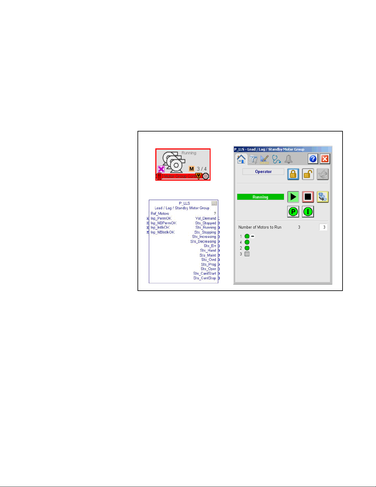
The following global object and faceplate images are examples of the graphical
interface tools for this Add-On Instruction.
Guidelines
Global Objects
Add-On Instruction
Use this instruction to control a group of motors, such as a set of pumps with
common intake source and discharge destination. The number of motors to run
depends on the demand on the system. The P_LLS group can be configured to
consist of as few as 2 or as many as 30 motors. The minimum demand can be set
as low as 0, so that all motors are stopped at minimum demand. The maximum
demand can be set as high as the number of pumps in the group. (In this case, if
the demand were as high as the number of pumps in the group, there would be no
'standby' pumps.)
Faceplate
Rockwell Automation Publication SYSLIB-RM054B-EN-P - February 2017 7
Page 8

Lead/Lag/Standby Motor Group (P_LLS)
IMPORTANT
To automate the group of motors, logic outside the P_LLS Add-On Instruction
must determine the demand and the number of motors in the group to run.
Every Lead / Lag / Standby control strategy consists of two basic parts: the logic
that determines number of motors to run (the demand), and the logic that
determines which motors to run. The P_LLS instruction provides the second
part of such a strategy. The logic that determines the demand varies from
application to application. The developer of each application must provide and
test this logic.
An operator or other logic determines the demand for motors. The P_LLS
instruction determines which motors to run to meet demand. In order for P_LLS
to start and stop motors in the group, they must be 'available'. A motor is available
when it has no faults and is in Program Mode.
The P_LLS instruction uses a sorting algorithm to deal with motors that are not
available. If a motor is running and not available (perhaps running in Operator
Mode), the motor is forced to the top of the sort. If a motor is stopped and not
available (perhaps faulted), the motor is forced to the bottom of the sort. The
motors that are available to start and stop are controlled to meet the demand. If
the demand cannot be met because of unavailable motors, a status/alarm
is provided.
EXAMPLE
Two motors in a group of four are stopped and not available. The P_LLS
instruction raises a 'can’t start' alarm when the demand reaches three because
there are only two motors available to run.
The P_LLS instruction uses an array of structures of the type 'P_LLS_Motor' to
interface to the motors. Each interface element in the array provides the signals
that are required between the P_LLS instruction and one motor. Configuration
data for the motor are also provided in the array. This data includes Priority and
Preference values that can be used to affect the sorting of the motors. A
Maintenance 'out of service' flag that removes a motor from consideration in the
sort is also included. The interface also includes a 'user sort' value that can be
used, for example, to push motors up or down the sort based on accumulated
runtime or other criteria.
8 Rockwell Automation Publication SYSLIB-RM054B-EN-P - February 2017
Page 9

Lead/Lag/Standby Motor Group (P_LLS)
Functional Description
The P_LLS Instruction controls and monitors a group of 2 to 30 motors and
provides:
• Operator, Program, and Override capability to start and stop the group (as
a group).
• Ability for the Operator or Program to enter a 'demand', the number of
motors to run.
• Configurable maximum demand (1 to number of motors in group).
• Configurable minimum demand (0 to maximum demand).
• Configurable to stop the last started motor or the first started motor
(first-on-last-off or last-on-last-off).
• Configurable delay between starts and configurable delay between stops.
• Start and Stop commands on the P_LLS instruction allow for starting or
stopping the motors as a group. The delay between starts or stops can be
configured to sequence the motors.
• Starts or stops motors as required to meet the entered demand.
• Identifies (and optionally alarms) when there are not enough motors
available to start (in Program Mode and ready to run) for the given
demand to be met.
• Identifies (and optionally alarms) when there are not enough motors
available to stop (in Program Mode and ready to stop) for the given
demand to be met.
• Ability to rotate the list of motors (demote the lead, promote the others).
• Monitoring of Permissive conditions to allow starting the motor group.
• Monitoring of Interlock conditions to stop/prevent starting the
motor group.
• Alarm if interlock conditions cause the group to be stopped.
• Supports HMI 'breadcrumbs' for Alarm Inhibited, Bad Configuration,
Not Ready, and Maintenance Bypass Active.
• 'Available' status for use by automation logic to know whether motor group
can be controlled by other objects.
Rockwell Automation Publication SYSLIB-RM054B-EN-P - February 2017 9
Page 10

Lead/Lag/Standby Motor Group (P_LLS)
Required Files
Add-On Instructions are reusable code objects that contain encapsulated logic
that can streamline implementing your system. With this code, you can create
your own instruction set for programming logic as a supplement to the
instruction set provided natively in the ControlLogix® firmware. An Add-On
Instruction is defined once in each controller project, and can be instantiated
multiple times in your application code as needed.
Controller File
The P_LLS_3_5-00_AOI.L5X Add-On Instruction must be imported into the
controller project to be used in the controller configuration. The service release
number (boldfaced) can change as service revisions are created.
Visualization Files
This Add-On Instruction has associated visualization files that provide a
common user interface. These files can be downloaded from the Product
Compatibility and Download Center at
http://www.rockwellautomation.com/rockwellautomation/support/pcdc.page.
IMPORTANT
The visualization file dependencies require Process Library content imports to
occur in a specific order as reflected in the following tables:
• Images
• Global Objects
• Standard Displays
• HMI Tags
• Macros
Images are external graphic files that can be used in displays. They must be
imported for FactoryTalk View to make use of them.
When PNG files are imported, they are renamed by FactoryTalk View with
a .bmp file extension, but retain a .png format.
Table 2 - Visualization Files: Images (.png)
FactoryTalk View SE Software FactoryTalk View ME Software Description
All .png files in the images folder All .png files in the images folder These are the common icons used in the global objects and
standard displays for all Process Objects.
The Global Object files (.ggfx file type) in the following table are Process Library
display elements that are created once and referenced multiple times on multiple
displays in an application. When changes are made to a Global Object, all
instances in the application are automatically updated.
Table 3 - Visualization Files: Global Objects (.ggfx)
FactoryTalk View SE Software FactoryTalk View ME Software Description
(RA-BAS) Common Faceplate Objects (RA-BAS-ME) Common Faceplate Objects Global objects used on process object faceplates.
10 Rockwell Automation Publication SYSLIB-RM054B-EN-P - February 2017
Page 11
Lead/Lag/Standby Motor Group (P_LLS)
Table 3 - Visualization Files: Global Objects (.ggfx)
FactoryTalk View SE Software FactoryTalk View ME Software Description
(RA-BAS) P_LLS Graphics Library (RA-BAS-ME) P_LLS Graphics Library P_LLS global object device symbols used to build
(RA-BAS) Process Alarm Objects (RA-BAS-ME) Process Alarm Objects Global objects used for managing alarms on process
(RA-BAS) Process Diagnostic Objects (RA-BAS-ME) Process Diagnostic Objects Diagnostic global objects used on process object
(RA-BAS) Process Faceplate Motor Objects (RA-BAS-ME) Process Faceplate Motor Objects Motor global objects used on process object faceplates.
(RA-BAS) Process Help Objects (RA-BAS-ME) Process Help Objects Global objects used for all process objects help displays.
(RA-BAS) Process Interlock Objects (RA-BAS-ME) Process Interlock Objects Global objects used for managing interlocks and
(RA-BAS) Process Mode Objects (RA-BAS-ME) Process Mode Objects Global objects used for managing modes on process
process graphics.
object faceplates.
faceplates.
permissives on process object faceplates.
object faceplates.
The Standard Display files (.gfx file type) in the following table are the Process
Library displays that you see at runtime.
Table 4 - Visualization Files: Standard Displays (.gfx)
FactoryTalk View SE Software FactoryTalk View ME Software Description
(RA-BAS) Common-AnalogEdit N/A Faceplate used for analog input data entry. The FactoryTalk
(RA-BAS) P_Alarm-Faceplate (RA-BAS-ME) P_Alarm-Faceplate The faceplate that is used for managing alarms for
(RA-BAS) P_Alarm-Help (RA-BAS-ME) P_Alarm-Help Alarm Help information that is accessed from the
(RA-BAS) P_LLS-Faceplate (RA-BAS-ME) P_LLS-Faceplate The faceplate that is used for the object
(RA-BAS) P_LLS-Quick (RA-BAS-ME) P_LLS-Quick The Quick display that is used for the object
(RA-BAS) P_Mode-Config (RA-BAS-ME) P_Mode-Config The Configuration Display used to configure the
(RA-BAS) Process Motor Family-Help (RA-BAS-ME) Process Motor Family-Help The Help display for Motor objects
(RA-BAS) P_Intlk-Faceplate (RA-BAS-ME) P_Intlk-Faceplate Optional
(RA-BAS) P_Perm-Faceplate (RA-BAS-ME) P_Perm-Faceplate Optional
(RA-BAS) Process Interlock Family-Help (RA-BAS-ME) Process Interlock Family-Help Optional
View ME faceplates use the native analog input data entry
so no file is required.
the object.
P_AIarm faceplate.
P_Mode object.
The interlock faceplate used for the object.
Use this file if your Discrete Output has an associated
P_Intlk object and you enable navigation to its faceplate
from the Discrete Output faceplate.
Permissive faceplate that is used for the object
Use this file if your object has an associated P_Perm object
and you enable navigation to the P_Perm faceplate from
the object faceplate.
Interlock/permissives help display that is used for
the object
Use this file if you use the P_Intlk or P_Perm faceplate.
HMI Tags are created in a FactoryTalk View ME application to support tab
switching on Process Library faceplates. The HMI tags may be imported via the
comma-separated values file (.csv file type) in the following table.
Rockwell Automation Publication SYSLIB-RM054B-EN-P - February 2017 11
Page 12

Lead/Lag/Standby Motor Group (P_LLS)
Table 5 - Visualization Files: HMI Tags (.csv)
FactoryTalk View SE Software FactoryTalk View ME Software Description
N/A FTVME_PlantPAxLib_Tags_3_5_xx.csv
where xx = the service release number.
These tags must be imported into the
FactoryTalk View ME project to support switching tabs on
any Process Object faceplate.
In a FactoryTalk View SE application, a macro is a series of commands stored in a
text file. In FactoryTalk View ME application, a macro is a list of tag assignments
stored in a text file. The following table lists the Macros (.mcr file type) used by
the Process Library.
Table 6 - Visualization Files: Macros (.mcr file)
FactoryTalk View SE Software FactoryTalk View ME Software Description
NavToP_LLS_Motor N/A This macro must be imported into the FactoryTalk View SE
project to support navigation to the Motor faceplate from
the P_LLS faceplate.
12 Rockwell Automation Publication SYSLIB-RM054B-EN-P - February 2017
Page 13
Lead/Lag/Standby Motor Group (P_LLS)
Controller Code
This section describes the parameter references for this Add-On Instruction.
Lead/Lag/Standby Motor Group InOut Structure
InOut parameters are used to link the Add-On Instruction to external tags that
contain necessary data for the instruction to operate. These external tags must be
of the data type shown.
Table 7 - P_LLS Drive InOut Parameters
Tag Name Data Type Description
Ref_Motors P_LLS_Motor Motor Interface Array (link to 2 to 30 motors)
The number of motors is on Engineering Tab Page 2. The tag pointed to by
Ref_Motors is used to interface between P_LLS and 2…30 motors.
Engineering Tab Page 2 on page 48) sets the number of motors.
(See
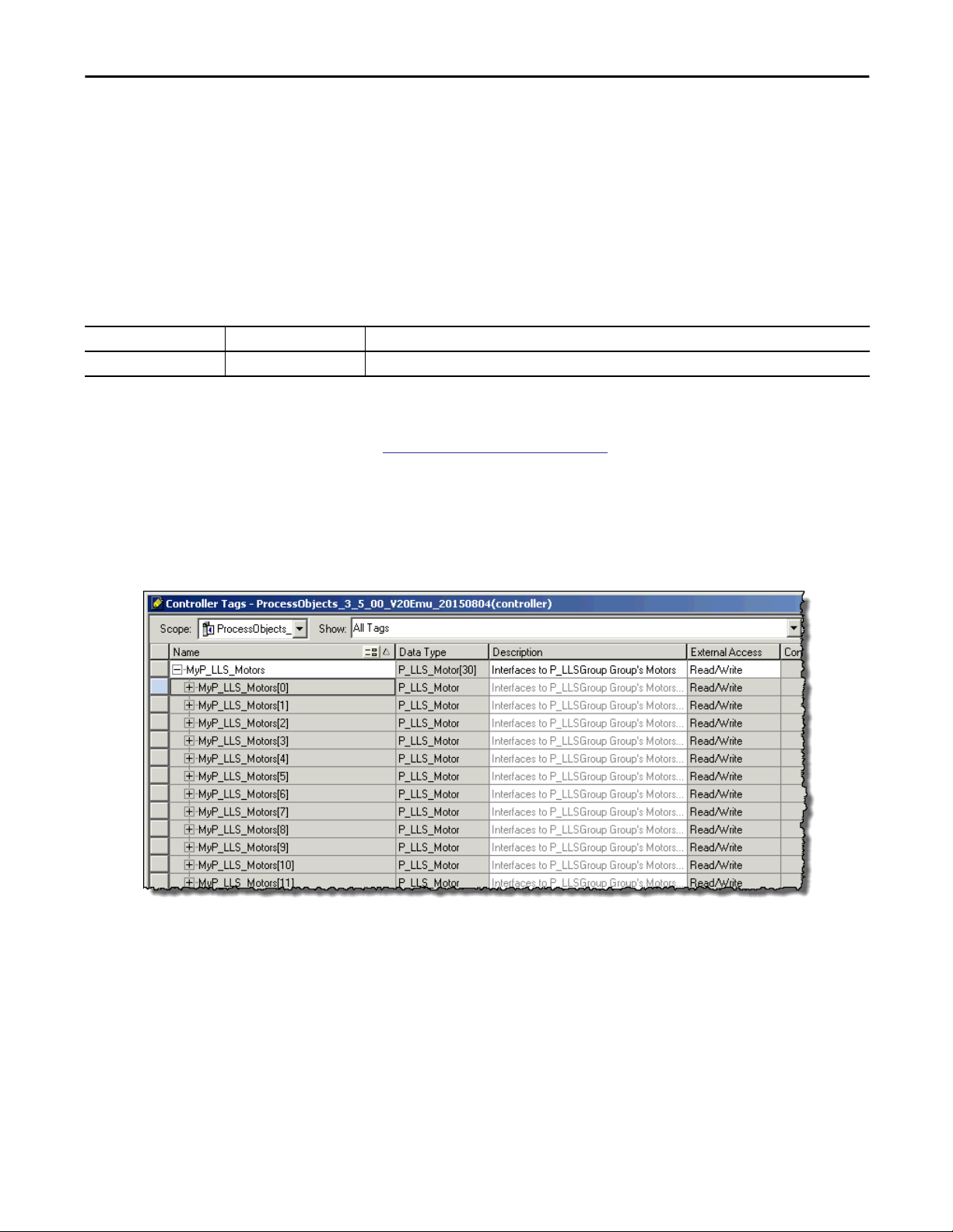
In the following example, the interface tag is named 'MyP_LLS_Motors'. The
type is an array of P_LLS_Motor structures. For each group of motors, create an
interface array. Name its tag the same as the P_LLS instruction backing tag, plus
'_Motors'. The array must have at least as many elements as there are motors in
the group.
Rockwell Automation Publication SYSLIB-RM054B-EN-P - February 2017 13
Page 14
Lead/Lag/Standby Motor Group (P_LLS)
This tag is an array of parameter values that facilitates communications between
P_LLS and an instance of P_Motor. The following table shows the contents of
each member of the array.
Table 8 - Array Member Content
Name Data Type Description
Inp_OtherSel DINT Other motor selection criteria (0...255) (input to LLS).
Inp_Demote BOOL Demote this motor to bottom of list (for example, on high runtime) (input to LLS).
Cfg_Prio DINT Motor priority in list (0...31 -- if unused, set to 0).
Cfg_Pref DINT Motor preference in list (0...31), all else being equal.
Cfg_NavTag STRING_NavTag Logix tag to navigate to for this motor (For example, P_Motor backing tag name).
IMPORTANT: This tag does not work in FactoryTalk ME.
PCmd_Start BOOL Program Command to start motor (output from LLS).
PCmd_Stop BOOL Program Command to stop motor (output from LLS).
PCmd_Acq BOOL Command to Acquire motor in Program mode (output from LLS).
PCmd_Rel BOOL Command to Release motor from Program mode (output from LLS).
MSet_OoS BOOL Maintenance setting to place motor Out of Service (input to LLS).
Sts_Available BOOL Motor is in Program mode and ready to operate (input to LLS).
Sts_Stopped BOOL Motor is confirmed stopped (input to LLS).
Sts_Starting BOOL Motor is starting (input to LLS).
Sts_Running BOOL Motor is confirmed running (input to LLS).
Sts_Stopping BOOL Motor is stopping (input to LLS).
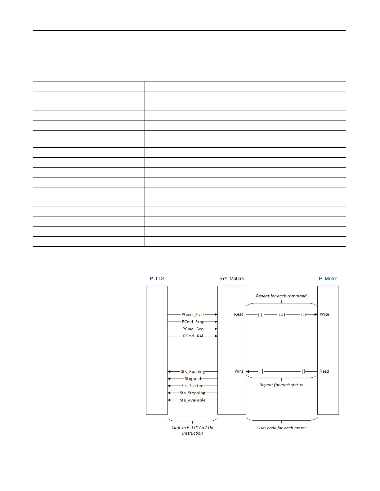
The following image shows the relationship between P_LLS, Ref_Motors
(interface), and P_Motor.
14 Rockwell Automation Publication SYSLIB-RM054B-EN-P - February 2017
Page 15
Lead/Lag/Standby Motor Group (P_LLS)
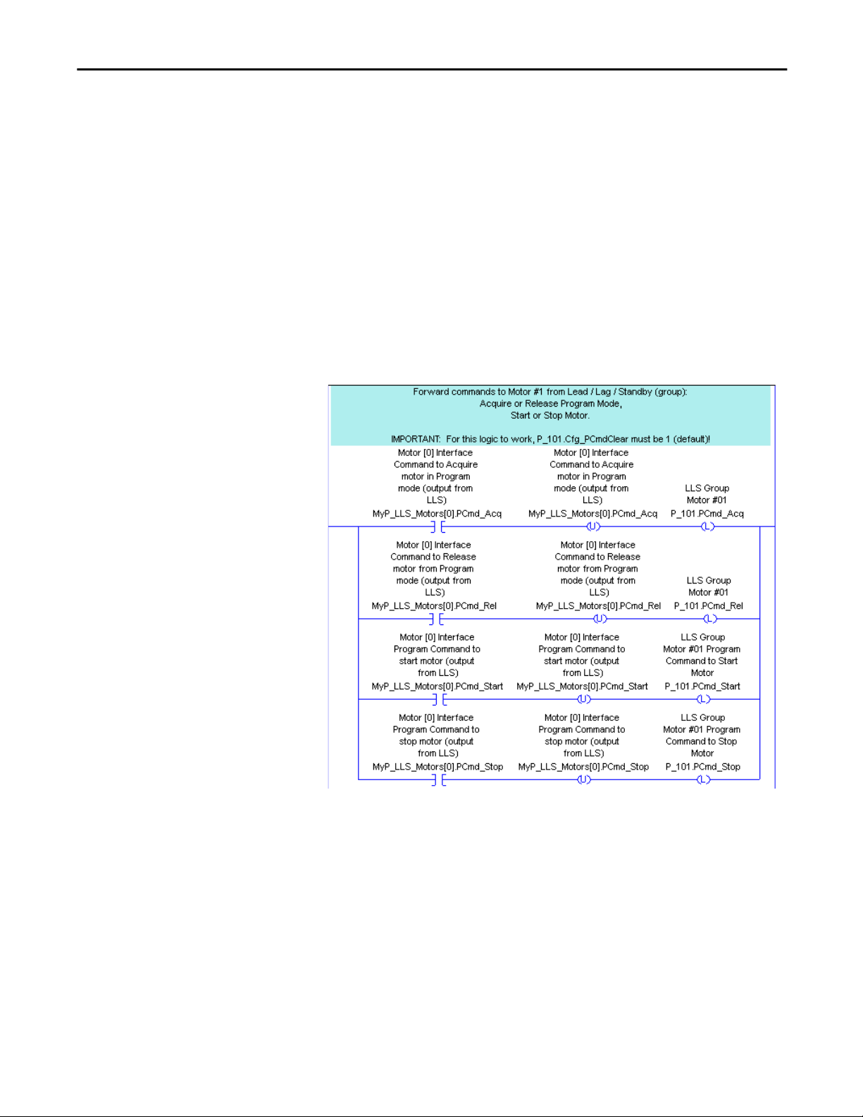
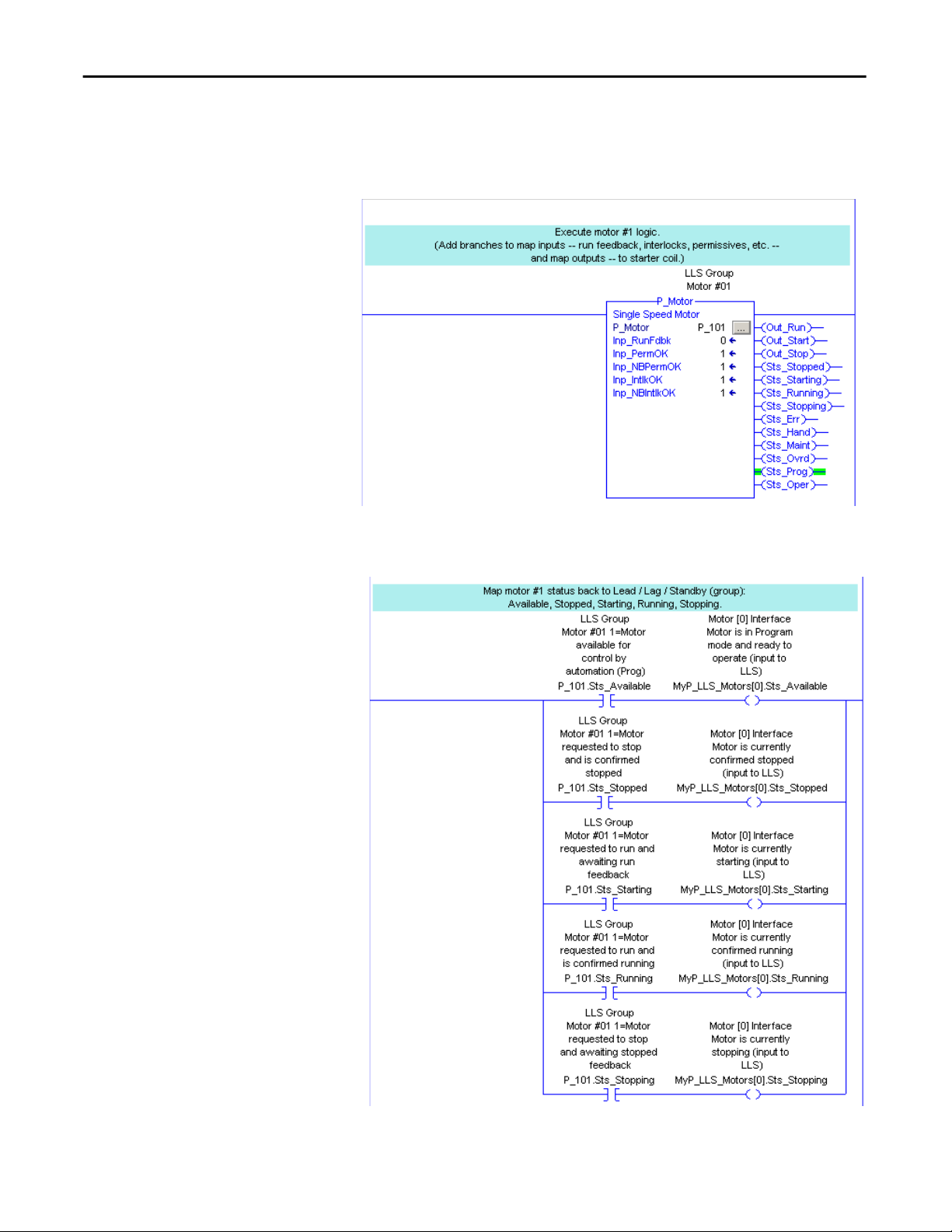
The following images show an example of the ladder logic for transferring
commands and motor status for one motor. Three steps are shown:
• Get motor status into P_LLS.
• Execute P_LLS to select which motors to run.
• Forward commands to the motor from P_LLS to the individual motors.
Each of the three steps is shown on its own rung. If desired, all three steps can be
in one branched rung.
In the following diagram, the process for forwarding each of the commands
(PCmd_Acq, PCmd_Rel, PCmd_Start, and PCmd_Stop) is:
• The appropriate bit in the interface is tested to see if it set.
• If the bit is set, the bit is cleared and the corresponding program command
on the motor is set.
TIP
The interface for the first motor in the group is element [0] of the interface
array tag.
TIP
This logic assumes that the motor is configured to clear program commands
upon receipt (Cfg_PCmd_Clear = 1, the default value).
Rockwell Automation Publication SYSLIB-RM054B-EN-P - February 2017 15
Page 16
Lead/Lag/Standby Motor Group (P_LLS)
Next, the motor logic is executed.
The motor logic uses the program commands to control the physical motor. The
motor logic also receives feedback from the motor.
The status (available, stopped, starting, running, and stopping) is read from the
motor and written to the interface.
16 Rockwell Automation Publication SYSLIB-RM054B-EN-P - February 2017
Page 17

Table 9 - P_LLS Input Parameters
Lead/Lag/Standby Motor Group (P_LLS)
Lead/Lag/Standby Motor Group Input Structure
Input parameters include the following:
• Input data elements (Inp_) are typically used to connect field inputs from
I/O modules or signals from other objects.
• Configuration data elements (Cfg_) are used to set configurable
capabilities and features of the instruction.
• Commands (PCmd_, OCmd_, MCmd_) are used by program logic,
operators, and maintenance personnel to request instruction actions.
• Settings (PSet_, OSet_, MSet_) are used by program logic, operators, and
maintenance personnel to establish runtime setpoints, thresholds, and so
forth. A Setting (without a leading P, O, or M) establishes runtime settings
regardless of role or mode.
Input Parameter Data
Type
EnableIn BOOL 1 Enable Input - System Defined Parameter
Inp_PermOK BOOL 1 1 = Permissives OK, Group can start
Inp_NBPermOK BOOL 1 1 = Non-bypassable Permissives OK, Group can start
Inp_IntlkOK BOOL 1 1 = Interlocks OK, Group can start/run
Inp_NBIntlkOK BOOL 1 1 = Non-bypassable Interlocks OK, Group can start/run
Inp_Hand BOOL Mode.Inp_Hand 0 1 = Select Hand (hardwired) Control Strategy
Inp_Ovrd BOOL Mode.Inp_Ovrd 0 1 = Select Override control strategy
Inp_OvrdDemand DINT 0 Override Mode setting for number of motors to run (MinDemand..MaxDemand)
Inp_OvrdCmd DINT 0 Override Mode command:
Inp_Reset BOOL 0 1 = Reset all fault conditions and latched Alarms
Cfg_NumMotors DINT 3 Number of motors in this Lead / Lag / Standby Group (2…30)
Cfg_MaxDemand DINT 2 Maximum number of motors to run (1…NumMotors)
Cfg_MinDemand DINT 0 Minimum number of motors to run (0…MaxDemand)
Cfg_FirstOnFirstOff BOOL 0 1 = First started is first stopped
Cfg_AllowRotate BOOL 1 1 = Allow Rotate ("cycle lead") command to rotate motor assignments
Cfg_RotateOnStop BOOL 1 1 = Rotate the lead to end of list upon stopping all motors
Cfg_HasPermObj BOOL 0 1 = Tells HMI a permissive object (for example, P_Perm) is used for Inp_PermOK
Alias For Default Description
0 = None
1 = Stop Group
2 = Start Group
3 = Rotate Assignments
IMPORTANT: If the Ref_Motors interface array has fewer elements than the
entered value, this value is reduced to the size of the array.
0 = First started is last stopped
and navigation to the permissive object faceplate is enabled.
IMPORTANT: The name of the Permissive object in the controller must be the
name of this object with the suffix ‘_Perm’. For example, if your P_LLS object has
the name ’LLS123’, then its Permissive object must be named ‘LLS123_Perm’.
Rockwell Automation Publication SYSLIB-RM054B-EN-P - February 2017 17
Page 18

Lead/Lag/Standby Motor Group (P_LLS)
Table 9 - P_LLS Input Parameters
Input Parameter Data
Type
Cfg_HasIntlkObj BOOL 0 1 = Tells HMI an interlock object (for example, P_Intlk) is used for Inp_IntlkOK and
Cfg_HasNav DINT 2#0000_0000
Cfg_SetTrack BOOL 1 This parameter is used to configure bumpless behavior of setting parameters when
Cfg_SetTrackOvrdHand BOOL 0 1 = Prog/Oper Settings track Override/Hand speed reference
Cfg_PCmdClear BOOL Mode.Cfg_PCmdClear 1 When this parameter is 1, program commands are cleared once they are acted
Cfg_ProgDefault BOOL Mode.Cfg_ProgDefault 0 This parameter defines the default mode. When this parameter is 1, the mode
Cfg_OperStopPrio BOOL 0 1 = OCmd_Stop has priority, accepted any time. If an operator stop command
Cfg_OCmdResets BOOL 0 1 = New Operator group command, resets fault
Cfg_OvrdPermIntlk BOOL 0 1 = Override ignores Bypassable Perm/Intlk
Cfg_HasCantStartAlm BOOL CantStart.Cfg_Exists 0 These parameters determine whether the corresponding alarm exists and is
Cfg_HasCantStopAlm CantStop.Cfg_Exists
Cfg_HasIntlkTripAlm IntlkTrip.Cfg_Exists
Cfg_CantStartResetReqd BOOL CantStart.Cfg_ResetReqd 0 These parameters determine whether a reset is required to clear the alarm status.
Cfg_CantStopResetReqd CantStop.Cfg_ResetReqd
Cfg_IntlkTripResetReqd IntlkTrip.Cfg_ResetReqd
Cfg_CantStartAckReqd BOOL CantStart.Cfg_AckReqd 1 These parameters determine whether an acknowledgement is required for an
Cfg_CantStopAckReqd CantStop.Cfg_AckReqd
Cfg_IntlkTripAckReqd IntlkTrip.Cfg_AckReqd
Alias For Default Description
navigation to the interlock object’s faceplate is enabled.
IMPORTANT: The name of the Interlock object in the controller must be this
object's name with the suffix ‘_Intlk’. For example, if your P_LLS object has the
name ’LLS123’, then its Interlock object must be named ‘LLS123_Intlk’.
Set bits indicate which Motor Navigation buttons are enabled
_0000_0000
_0000_0000
_0000_0000
switching modes.
When this parameter is 1:
• In Program mode, the operator settings track the program settings.
• In Operator mode, the program settings track the operator settings.
• The simulation inputs match the output values (transitions are bumpless).
When this parameter is 0, the instruction does not modify operator settings and
program settings. In this case, when the mode is changed, the effective value of
the setting can change depending on the program-set and operator-set values.
upon. When set to 0, program commands remain set until cleared by the
application program logic.
IMPORTANT: Clearing this parameter online can cause unintended program
command execution.
defaults to Program if no mode is being requested. When this parameter is 0, the
mode defaults to Operator if no mode is being requested.
IMPORTANT: Changing this parameter online can cause unintended mode
changes.
stops the group in a mode other than Operator or Maintenance, a Reset is required
to start the group.
0 = OCmd_Stop only in Operator/Maintenance mode
0 = Reset required to clear fault
0 = Always use Perm/Intlk
checked or if the alarm does not exist and is not used. When these parameters
are 1, the corresponding alarm exists.
When these parameters are 1, the alarm is latched ON when the alarm occurs. After
the alarm condition returns to normal, a reset is required to clear the alarm status.
For example, OCmd_Reset, Inp_Reset, or Drivefault.OCmd_Reset are required to
clear Alm_DriveFault alarm after the alarm is set and the value returns to normal.
When these parameters are 0, no reset is required and the alarm status is cleared
when the alarm condition returns to normal.
IMPORTANT: If the reset clears the alarm, it also acknowledges the alarm.
alarm. When these parameters are 1, the acknowledge (ack) bit is cleared when
the alarm occurs. An acknowledge command (for example, PCmd_FailAck or
Fail.OCmd_Ack) is required to acknowledge the alarm. When set to 0, the
Acknowledge bit is set when an alarm occurs indicating an acknowledged alarm
and no acknowledge command is required.
18 Rockwell Automation Publication SYSLIB-RM054B-EN-P - February 2017
Page 19

Table 9 - P_LLS Input Parameters
Lead/Lag/Standby Motor Group (P_LLS)
Input Parameter Data
Type
Cfg_CantStartSeverity INT CantStart.Cfg_Severity 750 These parameters determine the severity of each alarm. The severity drives the
Cfg_CantStopSeverity CantStop.Cfg_Severity 750
Cfg_IntlkTripSeverity IntlkTrip.Cfg_Severity 500
Cfg_StartDelay DINT 10 Time (seconds) after start or stop until next start is allowed (0…2M seconds)
Cfg_StopDelay DINT 10 Time (seconds) after start or stop until next stop is allowed (0…2M seconds)
PSet_Demand DINT 0 Program Setting for number of motors to run (MinDemand…MaxDemand)
PSet_Owner DINT 0 Program Owner Request ID (nonzero) or Release (zero)
OSet_Demand DINT 0 Operator Setting for number of motors to run (MinDemand…MaxDemand)
PCmd_Start BOOL 0 Program command to Start or Stop Motor Group
PCmd_Stop
PCmd_Rotate BOOL 0 Program command to rotate assignments (cycle lead to end of list)
PCmd_Acq BOOL Mode.PCmd_Acq 0 When Cfg_PCmdClear is 1:
PCmd_Rel Mode.PCmd_Rel
PCmd_Lock BOOL Mode.PCmd_Lock 0 When Cfg_PCmdClear is 1:
PCmd_Unlock Mode.PCmd_Unlock
PCmd_Reset BOOL 0 • Set PCmd_Reset to 1 to reset all alarms that require reset
PCmd_CantStartAck BOOL CantStart.PCmd_Ack 0 • Set PCmd_<Alarm>Ack to 1 to Acknowledge alarm
PCmd_CantStopAck CantStop.PCmd_Ack
PCmd_IntlkTripAck IntlkTrip.PCmd_Ack
PCmd_CantStartSuppress BOOL CantStart.PCmd_Suppress 0 When Cfg_PCmdClear is 1:
PCmd_CantStopSuppress CantStop.PCmd_Suppress
PCmd_IntlkTripSuppress IntlkTrip.PCmd_Suppress
PCmd_CantStartUnsuppress BOOL CantStart.PCmd_Unsuppress 0
PCmd_CantStopUnsuppress CantStop.PCmd_Unsuppress
PCmd_IntlkTripUnsuppress IntlkTrip.PCmd_Unsuppress
Alias For Default Description
color and symbol that are used to indicate alarm status on the faceplate and global
object.
The following are valid values:
1…250 = Low
251…500 = Medium
501…750 = High
751…1000 = Urgent
IMPORTANT: For FactoryTalk View software version 7.0, these severity parameters
drive the indication only on the global object and faceplate. The Alarms and Events
definition of severity drives the color and symbol that is used on the alarm banner
and alarm summary. The definition also drives the value returned by FactoryTalk
Alarms and Events display commands.
• Set PCmd_Acq to 1 to Acquire
• Set PCmd_Rel to 1 to Release
• These parameters reset automatically
When Cfg_PCmdClear is 0:
• Set PCmd_Acq to 1 to Acquire
• Set PCmd_Acq to 0 to Release
• PCmd_Rel is not used
• These Parameters Reset Automatically
• Set PCmd_Lock to 1 to Lock
• Set PCmd_Unlock to 1 to Unlock
• These parameters reset automatically
When Cfg_PCmdClear is 0:
• Set PCmd_Lock to 1 to Lock
• Set PCmd_Lock to 0 to Unlock
• PCmd_Unlock is not used
• These parameters do not reset automatically
• This parameter is always reset automatically
• The parameter is reset automatically
• Set PCmd_<Alarm>Suppress to 1 to suppress alarm
• Set PCmd_<Alarm>Unsuppress to 1 to unsuppress alarm
• These parameters reset automatically
When Cfg_PCmdClear is 0:
• Set PCmd_<Alarm>Suppress to 1 to suppress alarm
• Set PCmd_<Alarm>Suppress to 0 to unsuppress alarm
• PCmd_<Alarm>Unsuppress is not used
• These Parameters do not reset automatically
Rockwell Automation Publication SYSLIB-RM054B-EN-P - February 2017 19
Page 20

Lead/Lag/Standby Motor Group (P_LLS)
Table 9 - P_LLS Input Parameters
Input Parameter Data
Type
PCmd_CantStartUnshelve BOOL CantStart.PCmd_Unshelve 0 • Set PCmd_<Alarm>Unshelve to 1 to Unshelve alarm
PCmd_CantStopUnshelve CantStop.PCmd_Unshelve
PCmd_IntlkTripUnshelve IntlkTrip.PCmd_Unshelve
OCmd_Start BOOL 0 Operator command to start Motor Group
OCmd_Stop BOOL 0 Operator command to stop Motor Group
OCmd_Rotate BOOL 0 Operator command to rotate assignments (cycle lead to end of list)
OCmd_Bypass BOOL 0 Operator command to bypass all bypassable Interlocks and Permissives
OCmd_Check BOOL 0 Operator command to check (not bypass) all Interlocks and Permissives
MCmd_Disable BOOL 0 Maintenance command to disable motor
MCmd_Enable BOOL 0 Maintenance command to enable (allow to run) motor
MCmd_Acq BOOL Mode.MCmd_Acq 0 Maintenance command to acquire ownership (Operator/Program/Override to
MCmd_Rel BOOL Mode.MCmd_Rel 0 Maintenance command to release ownership (Maintenance to Operator/Program/
OCmd_AcqLock BOOL Mode.OCmd_AcqLock 0 Operator command to acquire (Program to Operator)/Lock ownership
OCmd_Unlock BOOL Mode.OCmd_UnlockRel 0 Operator command to unlock/release (Operator to Program) ownership
OCmd_Reset BOOL 0 Operator command to Reset all Alarms that require reset
OCmd_ResetAckAll BOOL 0 Operator command to Reset all Alarms and latched Shed conditions
Alias For Default Description
• The parameter is reset automatically
Maintenance)
Override)
20 Rockwell Automation Publication SYSLIB-RM054B-EN-P - February 2017
Page 21

Table 10 - P_LLS Output Parameters
Lead/Lag/Standby Motor Group (P_LLS)
Lead/Lag/Standby Motor Group Output Structure
Output parameters include the following:
• Value data elements (Val_) are numeric outputs of the instruction for use
by the HMI. Values can also be used by other application logic or software
packages.
• Status data elements (Sts_) are bit outputs of the instruction for use by the
HMI. Status bits can also be used by other application logic.
• Error data elements (Err_) are outputs of the instruction that indicate a
particular configuration error. If any Err_ bit is set, then the Sts_Err
configuration error summary status is set and the Invalid Configuration
indicator is displayed on the HMI.
• Not Ready data elements (Nrdy_) are bit outputs of the instruction for use
by the HMI for displaying the Device Not Ready indicator. These bits can
also be used by other application logic.
• Alarm data elements (Alm_) are outputs of the instruction that indicate a
particular alarm has occurred.
• Acknowledge data elements (Ack_) are outputs of the instruction that
indicate the corresponding alarm has been acknowledged.
• Ready data elements (Rdy_) are bit outputs of the instruction that are used
by the HMI to enable or disable command buttons and Setting entry
fields.
Input Parameter Data Type Alias For Description
EnableOut BOOL Enable Output: This instruction does not manipulate the EnableOut signal. Its output state
Val_Demand DINT Number of motors requested to run
Val_Cmd SINT Group command:
Val_Fdbk SINT Group Feedback 0…30 = Number of motors actually running
Val_Sts SINT Group Confirmed Status:
Val_Fault SINT Group Fault Status:
always reflects EnableIn input state.
0 = None
1 = Stop
2 = Start
0 = Powerup/Unknown
1 = Group Stopped
2 = Group Running
7 = Group Stopping (commanded to stop, waiting for motors to stop)
14 = Group Running and Demand Decreasing (waiting for a motor to stop)
15 = Group Running and Demand Increasing (waiting for a motor to start)
33 = Group Disabled
0 = None
12 = Can't Start enough motors to meet demand
13 = Can't Stop enough motors to meet demand
34 = Configuration Error
Rockwell Automation Publication SYSLIB-RM054B-EN-P - February 2017 21
Page 22

Lead/Lag/Standby Motor Group (P_LLS)
Table 10 - P_LLS Output Parameters
Input Parameter Data Type Alias For Description
Val_Mode SINT Mode.Val The current mode is shown with status bits and also as an enumeration ‘Val_Mode’ as follows:
0 = No mode
1 = Hand
2 = Maintenance
3 = Override
4 = Program (locked)
5 = Operator (locked)
6 = Program (unlocked, Operator is default)
7 = Operator (unlocked, Program is default)
8 = Program (unlocked, Program is default)
9 = Operator (unlocked, Operator is default)
Val_Owner DINT Current Object Owner ID (0 = not owned)
Val_Notify SINT Current Alarm Level and Acknowledgement (enumeration)
Val_RotateRank DINT Motor rank (0=Lead, and so forth) which are demoted on Rotate
Val_RotateID DINT Motor number that is demoted on Rotate
Sts_Stopped BOOL 1 = Motor group is requested to stop and all motors confirmed stopped
Sts_Running BOOL 1 = Motor group is requested to run
Sts_Stopping BOOL 1 = Motor group is requested to stop and not all motors confirmed stopped
Sts_Increasing BOOL 1 = Group is starting motors in sequence to get up to demand
Sts_Decreasing BOOL 1 = Group is stopping motors in sequence to get down to demand
Sts_Available BOOL 1 = Group available for control by automation (program)
Sts_Bypass BOOL 1 = Bypassable Interlocks and Permissives are bypassed
Sts_BypActive BOOL 1 = Bypassing Active (bypassed or maintenance)
Sts_Disabled BOOL 1 = Motor Group is disabled
Sts_NotRdy BOOL 1 = Group Not Ready, see detail bits for reason
Nrdy_Disabled BOOL 1 = Group Not Ready:
Nrdy_CfgErr
Nrdy_Intlk
Nrdy_Perm
Nrdy_OperPrio
Nrdy_NoMode
Sts_MaintByp BOOL 1 = A Maintenance Bypass is active, display icon
Sts_AlmInh BOOL 1 = An alarm is inhibited, disabled, or suppressed, display icon
Sts_Err BOOL 1 = Error in Configuration: see detail bits for reason
Err_Timer BOOL 1 = Error in Configuration: Start/Stop Check timer preset (use 0 …2,147,483)
Err_Alarm BOOL 1 = Error in Configuration: Alarm Throttle Time or Severity
Sts_MotorAvail DINT Set bits indicate which motors are available for program control
Sts_MotorStopped DINT Set bits indicate which motors are confirmed stopped
Sts_MotorStarting DINT Set bits indicate which motors are starting
Sts_MotorRunning DINT Set bits indicate which motors are confirmed running
Sts_MotorStopping DINT Set bits indicate which motors are stopping
Sts_Hand BOOL Mode.Sts_Hand 1 = Mode is Hand (supersedes maintenance, override, program, operator)
• Group is disabled by Maintenance
• Configuration error
• Interlock not OK
• Permissive not OK
• Operator Stop Priority command requires reset
• Group logic disabled / No mode
22 Rockwell Automation Publication SYSLIB-RM054B-EN-P - February 2017
Page 23

Lead/Lag/Standby Motor Group (P_LLS)
Table 10 - P_LLS Output Parameters
Input Parameter Data Type Alias For Description
Sts_Maint BOOL Mode.Sts_Maint 1 = Mode is Maintenance (supersedes override, program, operator)
Sts_Ovrd BOOL Mode.Sts_Ovrd 1 = Mode is Override (supersedes program, operator)
Sts_Prog BOOL Mode.Sts_Prog 1 = Mode is Program (auto)
Sts_Oper BOOL Mode.Sts_Oper 1 = Mode is Operator (manual)
Sts_ProgOperLock BOOL Mode.Sts_ProgOperLock 1 = Program or operator has requested Mode Lock
Sts_NoMode BOOL Mode.Sts_NoMode 1 = No mode (disabled because EnableIn is false)
Sts_MAcqRcvd BOOL Mode.Sts_MAcqRcvd 1 = Maintenance Acquire command received this scan
Sts_CantStart BOOL CantStart.Inp 1 = Not enough motors available to run
Sts_CantStop BOOL CantStop.Inp 1 = Not enough motors available to stop
Sts_IntlkTrip BOOL IntlkTrip.Inp 1 = Motor stopped by an Interlock Not OK (one-shot)
Alm_CantStart BOOL CantStart.Alm 1 = Alarm:
Alm_CantStop CantStop.Alm
Alm_IntlkTrip IntlkTrip.Alm
Ack_CantStart CantStart.Ack 1 = Alarm has been acknowledged:
Ack_CantStop CantStop.Ack
Ack_IntlkTrip IntlkTrip.Ack
Sts_CantStartDisabled CantStart.Disabled 1 = Alarm disabled by maintenance:
Sts_CantStopDisabled CantStop.Disabled
Sts_IntlkTripDisabled IntlkTrip.Disabled
Sts_CantStartShelved CantStart.Shelved 1 = Alarm shelved by operator:
Sts_CantStopShelved CantStop.Shelved
Sts_IntlkTripShelved IntlkTrip.Shelved
Sts_CantStartSuppressed CantStart.Suppressed 1 = Alarm suppressed by program:
Sts_CantStopSuppressed CantStop.Suppressed
Sts_IntlkTripSuppressed IntlkTrip.Suppressed
Rdy_Start BOOL 1 = Ready to receive OCmd for (enables HMI button):
Rdy_Stop
Rdy_Rotate
Rdy_Bypass
Rdy_Check
Rdy_Demand BOOL 1 = Ready to receive OSet_Demand (enables numeric entry)
Rdy_Disable BOOL 1 = Ready to receive MCmd_Disable (enables HMI button)
Rdy_Enable BOOL 1 = Ready to receive MCmd_Enable (enables HMI button)
Rdy_Reset BOOL 1 = At least one Alarm or Latched Shed requires Reset
Rdy_ResetAckAll BOOL 1 = At least one Alarm or latched Shed condition requires Reset or Ack
P_LLS BOOL Unique Parameter Name for auto - discovery
• Not enough motors available to run
• Not enough motors available to stop
• Motor stopped by an Interlock Not OK
• Not enough motors available to run
• Not enough motors available to stop
• Interlock Trip
• Not enough motors available to run
• Not enough motors available to stop
• Interlock Trip (also not saved)
• Not enough motors available to run
• Not enough motors available to stop
• Interlock Trip
• Not enough motors available to run
• Not enough motors available to stop
• Interlock Trip
• Start
• Stop
• Rotate
• Bypass
• Check
Rockwell Automation Publication SYSLIB-RM054B-EN-P - February 2017 23
Page 24

Lead/Lag/Standby Motor Group (P_LLS)
Lead/Lag/Standby Motor Group Local Configuration Tags
Configuration parameters that are array, string, or structure data types cannot be
configured as parameters for Add-On Instructions. Configuration parameters of
these types appear as local tags to the Add-On Instruction. Local tags can be
configured through the HMI faceplates or in Studio 5000 Logix Designer®
application. Open the Instruction Logic of the Add-On Instruction instance and
then open the Data Monitor on a local tag. These parameters cannot be modified
by using controller logic or Logix Designer application export/import
functionality.
Tag Name Data Type Default Description
Cfg_Desc STRING_40 'Lead / Lag / Standby Motor
Group'
Cfg_Label STRING_20 'Motor Group Control' Label for graphic symbol that is displayed on HMI. This string appears on the
Cfg_Tag STRING_20 'P_LLS' Tagname for display on HMI. This string is shown in the title bar of the
Description for display on HMI. This string is shown in the title bar of the
faceplate.
graphic symbol.
faceplate.
24 Rockwell Automation Publication SYSLIB-RM054B-EN-P - February 2017
Page 25

Lead/Lag/Standby Motor Group (P_LLS)
Operations
This section describes the primary operations for Add-On Instructions.
Modes
This instruction uses the following standard modes, which are implemented by
using an embedded P_Mode Add-On Instruction.
Table 11 - Modes
Mode Description
Operator The Operator owns control of the group. Operator commands (OCmd_) and Operator settings
(OSet_) from the HMI are accepted.
Program Program logic owns control of the group. Program commands (PCmd_) and Program settings
(PSet_) are accepted.
Override Priority logic owns control of the group and supersedes Operator and Program control. Override
Inputs (Inp_OvrdCmd and other Inp_OvrdXxxx values) are accepted. If so configured,
bypassable interlocks and permissives are bypassed.
Maintenance Maintenance owns control of the group and supersedes Operator, Program, and Override control.
Operator commands and settings from the HMI are accepted. Bypassable interlocks and
permissives are bypassed, and device timeout checks are not processed.
Hand Hardwired logic or other logic outside the instruction owns control of the group. The instruction
tracks the state of the device for bumpless transfer back to one of the other modes.
No Mode The device is disabled and has no owner because the EnableIn input is false. The main
instruction Logic routine is not being scanned. See Execution section for more information on
EnableInFalse processing.
See Rockwell Automation Library of Process Objects: Common Mode Block
(P_Mode) Reference Manual, publication SYSLIB-RM005, for more
information.
Alarms
This instruction uses the following alarms, which are implemented by using
embedded P_Alarm and P_Gate Add-On Instructions.
Alarm Name P_Alarm Name P_Gate Name Description
Can’t Start CantStar t None Raised when there are not enough motors available to
start to satisfy the entered Demand. Too many motors
are faulted or stopped in a mode other than Program.
Can’t Stop CantStop None Raised when there are not enough motors available to
stop to satisfy the entered Demand. Too many motors
are running in a mode other than Program.
Interlock Trip IntlkTrip None Raised when the motor is running and an interlock
'not OK' condition causes the motor to stop.
If interlocks are not bypassed, a bypassable interlock
or a non-bypassable interlock 'not OK' condition
initiates an interlock trip. If interlocks are bypassed,
only a non-bypassable interlock 'not OK' condition
initiates an interlock trip.
Parameters of the P_Alarm object can be accessed by using the following
convention: [P_Alarm Name].[P_Alarm Parameter].
Rockwell Automation Publication SYSLIB-RM054B-EN-P - February 2017 25
Page 26

Lead/Lag/Standby Motor Group (P_LLS)
Simulation
P_LLS does not have a simulation capability.
Execution
The following table explains the handling of instruction execution conditions.
Condition Description
EnableIn False (false rung) Handled the same as if the group is disabled by command.
The motor outputs are de-energized and the group is
shown as disabled on the HMI. The mode is shown as No
mode. All alarms are cleared.
Powerup (prescan, first scan) Any commands received before first scan are discarded.
The motor is de-energized and treated as if it were
commanded to stop.
Embedded P_Mode and P_Alarm instructions are
handled in accordance with their standard powerup
procedures. See the Reference Manuals for the P_Mode
and P_Alarm instructions for details.
Postscan (SFC transition) No SFC postscan logic is provided.
See the Logix5000™ Controllers Add-On Instructions Programming Manual,
publication
1756-PM010, for more information.
26 Rockwell Automation Publication SYSLIB-RM054B-EN-P - February 2017
Page 27

Lead/Lag/Standby Motor Group (P_LLS)
.
e
s
Thto
.
.
and re-sorting the list
bits for the Lead pump
NOTE: “Rotate” functions ar
implemented by clearing the
1 1 1 1
1 1 1 1
1 1 1 0
1 1 1 0
1 1 0 1
1 1 0 1
1 1 0 0
1 1 0 0
1 1 1 1
1 1 1 0
1 1 0 1
1 1 0 0
1 0 1 1
1 0 1 0
1 0 0 1
1 0 0 0
1
1
1
1
1
1
1
1
.
...
Lead-Lag-Spare Pump Sort Algorithm
PAGE TI TLE:
all preferences to the same valve (zero)
User-defined set of 8 bits
These bits supersede the
not the configured Priority
Ref_Motors[n].Inp_OtherSel
x x x xx x x x
configured Preference, but
(unsigned) for modifying sort
To allow lower b its to come into sort, set
...
1 1 1 1
1 1 1 0
1 1 0 1
1 1 0 0
1 0 1 1
1 0 1 0
1 0 0 1
Ref_Motors[n].Cfg_Prio Ref_Motors[n].Cfg_Pref
1
1
1
1
1
Status Value Configured Pump Priority User-Input Select Value (e.g., func tion of run time) Configured Pump Preference Current Position value
31 30 29 28 27 26 25 24 23 22 21 20 19 18 17 16 15 14 13 12 11 10 9 8 7 6
als ...
als ...
als ...
.....................
als ...
als ...
als ...
1 0 000 1 0
0 0 1
Highest Priority Pump
Next Highest Priority Pump
list)
start or stop )
lable to start)
ilable to stop)
1 0 0 0
1
1
1
signed integer bit pattern) to determine Lead / Lag / 2nd Lag ... order.
all priorities to the same valve (zero)
To allow lower b its to come into sort, set
KEY CONCEPT: The list of pumps is sorted (by desce ndi ng numeric value, based on
Rockwell Automation Publication SYSLIB-RM054B-EN-P - February 2017 27
Page 28

Lead/Lag/Standby Motor Group (P_LLS)
Motor Sort Algorithm
To determine the order in which the motors (pumps) are started, signed integer
bit patterns for each motor are sorted by numeric value. The following list is the
order in which the bit patterns are evaluated when sorting:
• Out of service bit
• Status value
• Priority value
• User-input value
• Preference value
• Current position value
Out of Service (Bit 31)
This bit is used to flag the motor out of service (value = 1) and automatically send
it to the bottom of the list. If this bit = 0, the motor is free to operate and bits
5…30 determine its start order.
If multiple motors are out of service, bits 5…30 determine their position at the
bottom of the list.
Out of service motors are not commanded and are not counted as running even if
actually running.
Status Value (Bits 30…28)
The status of the motor determines the value of these bits:
• 100 - The motor is in Hand and is not available to stop
• 010 - The motor is in Auto and is free to start or stop
• 001 - The motor is Off and is not available to start
If all motors have the same value, these bits do not affect the sort; the next set of
bits become the determining factor in the sort.
Priority Value (Bits 27…23)
These bits are next in the order of precedence for sorting the array list. The value
of these bits corresponds to the number entered in the Motor Priority field in the
Motor Configuration dialog box (
page 50).
The highest priority value has a pattern of '11111' (31), the next highest priority
value is '11110' (30), and so forth.
If this priority is not to be used for the sort, set the priority value to zero for
every motor.
If all motors have the same value, these bits do not affect the sort; the next set of
bits become the determining factor in the sort.
28 Rockwell Automation Publication SYSLIB-RM054B-EN-P - February 2017
Page 29

Lead/Lag/Standby Motor Group (P_LLS)
User-input Values (Bits 22…15)
If the Status Values are equal and the Priority values are equal, enter values in
these bits to sort the motors in the array list to the desired order.
The highest user-input value has a pattern of '11111111' (255), the next highest
user-input value is '11111110' (254), and so forth.
If this value is not to be used for the sort, set the value to zero for every motor.
If all motors have the same value, these bits do not affect the sort; the next set of
bits become the determining factor in the sort.
Preference Value (Bits 14…10)
These bits are next in the order of precedence for determining the order of the
motors in the array list. The value of these bits corresponds to the number
entered in the Motor Preference field in the Motor Configuration dialog
page 50).
box (
The highest preference value has a pattern of '11111' (31), the next preference
value is '11110' (30), and so forth.
If this value is not to be used for the sort, set the value to zero for every motor.
If all motors have the same value, these bits do not affect the sort; the next set of
bits become the determining factor in the sort.
Current Position (Bits 9…5)
IMPORTANT
These bits are next in the order of precedence for determining the order of the
motors in the array list. The value of these bits corresponds to the value of the
current position of the motor in the list, and the value is established by the
P_LLS instruction. There is no user entry for this field.
• Lead motor - '11111' (31)
• First Lag motor - '11110' (30)
• Second Lag motor - '11101' (29) and so on …
The Status value, Priority value, User-input value, and Preference value must be
equal for all motors for the Current Position to be a determining factor in the
sort.
The current position bits are the only set of bits that cannot be equal.
Rockwell Automation Publication SYSLIB-RM054B-EN-P - February 2017 29
Page 30

Lead/Lag/Standby Motor Group (P_LLS)
Display Elements
A display element (global object) is created once and can be referenced multiple
times on multiple displays in an application. When changes are made to the
original (base) object, the instantiated copies (reference objects) are
automatically updated. Use of global objects, with tag structures in the
ControlLogix system, aid consistency and save engineering time.
Table 12 - P_LLS Display Elements
Display Element Name Display Element Description
GO_P_LLS_Motors Motors in right position acting as a group.
GO_P_LLS_Blowers Blower in right position acting as a group.
GO_P_LLS_Pumps Pumps in right position acting as a group.
Common attributes of the P_LLS graphic symbols include the following:
• Graphical representation of the device
• Current state of the motor in text
• Status/quality indicators
• Mode indicator
• Label
• Alarm indicator that changes color for the severity of the alarm
• Alarm border that changes color on an alarm and blinks on an
unacknowledged alarm
• Maintenance Bypass indicator
• Number of Motors to Run/Maximum Demand indicator
Alarm Border
Status/Quality
Indicator
State
Mode Indicator
Number of Motors to
Run/Maximum Demand
Alarm Indicator
Label
30 Rockwell Automation Publication SYSLIB-RM054B-EN-P - February 2017
Status/Quality
Indicator
Maintenance
Bypass Indicator
Page 31

Lead/Lag/Standby Motor Group (P_LLS)
Each graphic symbol includes a touch field over it that opens the object faceplate.
In addition, there is a tooltip on the graphic symbol that displays the configured
tag and description of the object.
State Indicators
The state indicator text changes and the graphic symbol color changes depending
on the state of the group.
Table 13 - Motor State Indicator Colors
Color State
Blue Increasing, decreasing, or stopping
White Running
Dark Gray Stopped
Status/Quality Indicators
One of these symbols appears on the graphic symbol when the described
condition is true.
Graphic Symbol Description
Invalid configuration.
Data quality bad/failure.
Data Quality degraded: uncertain, test, simulation, substitution, or out of specification.
The group has been disabled.
Device not ready to operate.
Rockwell Automation Publication SYSLIB-RM054B-EN-P - February 2017 31
Page 32

Lead/Lag/Standby Motor Group (P_LLS)
Graphic Symbol Description
Motor running.
Motor idle.
Motor not controllable.
No symbol displayed I/O communication and quality good, configuration valid.
TIP
When the Invalid Configuration indicator appears, you can find which
configuration setting is invalid by following the indicators. Click the graphic
symbol to open the faceplate. The Invalid Configuration indicator appears on
the appropriate tab at the top of the faceplate to guide you in finding the
configuration error. Navigate to the tab and the condition with an invalid
configuration appears in a magenta box.
For the Lead/Lag/Standby Motor Group Add-On Instruction, the Invalid
Configuration indicator appears under the following conditions:
• The Start/Stop check time preset is set to a value less than zero or greater
than 2,147,483 seconds.
• Alarm Severity is set to a value less than 1 or greater than 1000.
• An alarm minimum on time is set to a value less than zero or greater than
2,147,483 seconds.
TIP
When the Device Not Ready indicator appears, you can find what condition is
preventing operation by following the indicators. Click the graphic symbol to
open the faceplate. The Device Not Ready indicator appears on the appropriate
tab at the top of the faceplate to guide you in finding the condition. Navigate
to the tab and the condition preventing operation has this indicator next to it.
For the Lead/Lag/Standby Motor Group Instruction, the Not Ready indicator
appears under the following conditions:
• Group disabled by Maintenance.
• There is an invalid configuration.
• Interlocks are not OK and not bypassed. Non-bypassable interlocks are
not OK.
• Permissives are not OK and not bypassed. Non-bypassable permissives are
not OK.
• Operator Stop Priority command requires reset.
• Group logic is disabled or there is no mode.
32 Rockwell Automation Publication SYSLIB-RM054B-EN-P - February 2017
Page 33

Lead/Lag/Standby Motor Group (P_LLS)
For each motor, the Motor Not Controllable indicator appears under the
following conditions:
• Motor not in Program mode.
• Motor not ready to be commanded.
• Motor Out of Service (see P_LLS faceplate,
Maintenance Tab Page 2 on
page 45
• Motor disabled (on the Maintenance Tab of the motor faceplate)
Mode Indicators
One of these symbols appears on the right side of the graphic symbol to indicate
the mode of the object instruction.
Graphic Symbol Description
Transparent Operator mode (if the default mode is Operator and the current mode is Operator, the mode
indicator is transparent).
Operator mode (if the default mode is Program).
Operator mode locked.
Transparent Program mode (if the default mode is Program and the current mode is Program, the mode
TIP
indicator is transparent).
Program mode (if the default mode is Operator).
Program mode locked.
Override mode
Maintenance mode.
Hand mode
No mode.
The images provided for the Operator and Program default modes are
transparent; therefore, no mode indicators are visible if the device is in its
default mode. This behavior can be changed by replacing the image files for
these mode indicators with images that are not transparent.
Rockwell Automation Publication SYSLIB-RM054B-EN-P - February 2017 33
Page 34

Lead/Lag/Standby Motor Group (P_LLS)
See Rockwell Automation Library of Process Objects: Common Mode Block
(P_Mode) Reference Manual, publication
SYSLIB-RM005, for more
information.
Alarm Indicators
One of these symbols appears on the left side of the label to indicate the described
alarm condition and the alarm border and label background change color. The
alarm border and label background blink if acknowledgement of an alarm
condition is required. Once the alarm is acknowledged, the alarm border and
label background remain the color that corresponds to the severity of the alarm.
Symbol Border and Label Background Description
No change in color Alarm Inhibit: an alarm is suppressed by the Program,
disabled by Maintenance, or shelved by the Operator.
White Return to normal (no alarm condition), but a previous
Blue Low severity alarm.
Yellow Medium severity alarm.
Red High severity alarm.
Magenta Urgent severity alarm.
No symbol No change in color No alarm or alarm inhibit condition, and all alarms
alarm has not been acknowledged.
are acknowledged.
See Rockwell Automation Library of Process Objects: Common Alarm Block
(P_Alarm) Reference Manual, publication
SYSLIB-RM002, for more
information.
Maintenance Bypass Indicator
This symbol appears to the right of the label to indicate that a maintenance
bypass has been activated.
TIP
When the Maintenance Bypass indicator appears, you can find what condition
was bypassed by following the indicators. Click the graphic symbol to open the
faceplate. The Maintenance Bypass indicator appears next to the appropriate
tab at the top of the faceplate to guide you in finding the bypass. Once you
navigate to the tab, the bypassed item is flagged with this indicator.
For the Lead/Lag/Standby Motor Group Add-On Instruction, the Maintenance
bypass indicator appears under the following conditions:
• Bypassable interlocks and permissives have been bypassed.
34 Rockwell Automation Publication SYSLIB-RM054B-EN-P - February 2017
Page 35

Lead/Lag/Standby Motor Group (P_LLS)
• Motor taken out of service (See Maintenance Tab Page 2 on page 45).
Using Global Elements
The global objects for P_LLS can be found in the global object file
(RA-BAS-ME) P_LLS Graphics Library.ggfx for FactoryTalk View ME or
(RA-BAS) P_LLS Graphics Library.ggfx for FactoryTalk View SE. Follow these
steps to use a global object.
1. Copy the global object from the global object file and paste it in the
display file.
Rockwell Automation Publication SYSLIB-RM054B-EN-P - February 2017 35
Page 36

Lead/Lag/Standby Motor Group (P_LLS)
2. In the display, right-click the global object and choose Global Object
Parameter Values.
The Global Object Parameter Values dialog box appears.
The global object parameters are as follows.
Parameter Required Description
#102 Y Object tag to point to the name of the associated object Add-On Instruction
#103 Y Path used for display navigation features to other objects. Include program
#120 N Additional parameter to pass to the display command to open the faceplate.
#121 N Additional parameter to pass to the display command to open the faceplate.
#122 Y The options for the global object display are as follows:
in the controller.
scope if tag is a program scope tag.
Typically used to define position for the faceplate.
If defining X and Y coordinates, separate parameters so that #120 defines X
and #121 defines Y. This separation lets these parameters be used in
subsequent display commands originating from the faceplate.
0 = Always show faceplate
1 = Show Quick Display for users without Maintenance access (Code C)
2 = Always show Quick Display
3. In the Value column, type the tag or value as specified in the Description
column.
TIP
Click the ellipsis (…) to browse and select a tag.
Values for items marked ‘(optional)’ can be left blank.
4. Click OK.
36 Rockwell Automation Publication SYSLIB-RM054B-EN-P - February 2017
Page 37

Lead/Lag/Standby Motor Group (P_LLS)
Quick Display
The Quick Display screen provides means for operators to perform simple
interactions with the P_LLS instruction instance. From the Quick Display, you
can navigate to the faceplate for full access for operation, maintenance personnel,
and configuration.
Rockwell Automation Publication SYSLIB-RM054B-EN-P - February 2017 37
Page 38

Lead/Lag/Standby Motor Group (P_LLS)
Faceplate
The P_LLS faceplate consists of five tabs and each tab consists of one or
more pages.
The title bar of each faceplate contains the value of local configuration tags
Cfg_Tag and Cfg_Desc.
The Operator tab is displayed when the faceplate is initially opened. Click the
appropriate icon at the top of the faceplate to access a specific tab.
Maintenance
Operator Engineering
Diagnostics
Alarms
Help
Exit
The faceplate provides the means for operators, maintenance workers, engineers,
and others to interact with the P_LLS instruction instance. You can also view the
status and values and manipulate it through its commands and settings. When a
given input is restricted via FactoryTalk View security, the required user security
code letter is shown in the tables that follow.
38 Rockwell Automation Publication SYSLIB-RM054B-EN-P - February 2017
Page 39

Lead/Lag/Standby Motor Group (P_LLS)
Operator Tab
The Faceplate initially opens to the Operator (‘Home’) tab. From here, an
operator can monitor the group status and manually operate the group when it is
in Operator mode.
The Operator tab has buttons to start and stop the group when it is in the proper
mode and shows the following:
• Current mode (Program, Operator, Override, Maintenance, or Hand)
• Requested mode indicator (appears only if Operator or Program mode is
superseded by another mode)
• Group state (stopping, stopped, starting, or running)
• Interlock and permissive status and navigation buttons
• Individual motor state indicators
Reset and Acknowledge
All Alarms Command
Button
Current Mode Indicator
Individual Motor
State Indicators
Motor State Indicators
see
Table 13 on page 31
Operator Mode Unlock
and Lock Command
Buttons
Rotate Motor Assignment
Command Button
Interlock/Permissives
Indicator/Navigation
Buttons
Group Start and Stop
Command Buttons
IMPORTANT
Rockwell Automation Publication SYSLIB-RM054B-EN-P - February 2017 39
Click a motor number to open the associated motor faceplate.
See
Motor Configuration on page 50 for more information.
Page 40

Lead/Lag/Standby Motor Group (P_LLS)
The following table shows the functions included on the Operator tab.
Table 14 - Operator Tab Descriptions
Function Action Security
Click to lock in Operator mode. Function locks the mode in
Operator mode, preventing the program from taking control.
Click to unlock Operator mode. Function unlocks Operator
mode, letting the program take control.
Click to request Program mode.
Click to request Operator mode.
Manual Device
Operation (Code B)
Click to start group. Normal Operation of
Click to stop group.
IMPORTANT: Motors stop in reverse order of starting unless
First Started is first stopped on page 49 is checked.
Click to rotate motor assignments. The lead motor is demoted
to the end of the list. Motors are started or stopped to satisfy
Number of Motors to Run.
Click to open Interlock faceplate. None
Click to open Permissive faceplate.
Click to reset and acknowledge all alarms. Acknowledge Alarms
Number of Motors to Run Type a number between 0 and the maximum demand to
indicate the number of motors to run.
Devices (Code A)
(Code F)
Normal Operation of
Devices (Code A)
If the object is configured to have permissive or interlock objects (for example,
Cfg_HasPermObj or Cfg_HasIntlkObj is true), the permissive and interlock
indicators become buttons that open the faceplates of the source objects that are
used as a permissive or interlock. Often the source object is a P_Intlk object or a
P_Perm object. If the object is not configured in this way, the interlock or
permissive symbols are indicators only.
40 Rockwell Automation Publication SYSLIB-RM054B-EN-P - February 2017
Page 41

Lead/Lag/Standby Motor Group (P_LLS)
See the following publications for more information:
• Rockwell Automation Library of Process Objects: Interlock with First Out
and Bypass (P_Intlk) Reference Manual, publication
SYSLIB-RM004
• Rockwell Automation Library of Process Objects: Permissives with Bypass
(P_Perm) Reference Manual, publication
SYSLIB-RM007
One of these symbols appears to indicate the described Interlock or Permissive
condition.
Table 15 - Permissive and Interlock Status Indicators
Permissive Symbol Interlock Symbol Description
One or more conditions not OK
Non-bypassed conditions OK
All conditions OK, bypass active
All conditions OK
Alarm indicators appear on the Operator tab when the corresponding alarm
occurs.
Can’t Start Alarm
Can’t Stop Alarm
Interlock Trip Alarm
Rockwell Automation Publication SYSLIB-RM054B-EN-P - February 2017 41
Page 42

Lead/Lag/Standby Motor Group (P_LLS)
The following table shows the alarm status symbols that are used on the Operator
tab.
Table 16 - Operator Tab Alarm Status
Graphic Symbol Alarm Status
In Alarm (Active Alarm)
In Alarm and Acknowledged
Out of Alarm but not Acknowledged
Alarm Suppressed (by Program) (Alarm is logged but not displayed)
Alarm Disabled (by Maintenance)
Alarm Shelved (by Operator)
42 Rockwell Automation Publication SYSLIB-RM054B-EN-P - February 2017
Page 43

Lead/Lag/Standby Motor Group (P_LLS)
Maintenance Tab
Maintenance personnel use the information and controls on the Maintenance tab
to adjust device parameters. They also troubleshoot and temporarily work
around device problems and disable the device for routine maintenance.
The Maintenance tab is divided into two pages.
Maintenance Tab Page 1
Page 1 of the Maintenance tab shows the following:
• Current mode (Program, Operator, Override, Maintenance, or Hand).
• Requested modes indicator highlights all modes that have been requested.
The leftmost highlighted mode is the current mode.
• Motor Enabled/Disabled indicator.
• Interlock and permissive bypassed/enabled indicator and buttons.
Current Mode Indicator
Requested Mode Indicator
Interlock and Permissive
Bypassed/enabled
Indicator
Interlocks and
Permissives Bypassed
Indicator
Maintenance Mode Acquire
and Release Command
Buttons
Motor Enable and Disable
Command Buttons
Bypass/Check Interlocks
and Permissives Buttons
Rockwell Automation Publication SYSLIB-RM054B-EN-P - February 2017 43
Page 44

Lead/Lag/Standby Motor Group (P_LLS)
The following table shows the functions on page 1 of the Maintenance tab.
Table 17 - Maintenance Tab Page 1 Descriptions
Function Action Security Configuration Parameters
Click for Maintenance mode. Equipment
Maintenance
(Code C)
Click to release Maintenance mode.
Click to enable motor.
Click to disable motor.
None
In Override mode,
bypass Interlocks
and Permissives
that can be
bypassed
Bumpless Program/
Operator transition
Bumpless transition
from Override/Hand
to Program/
Operator
Click to enable checking of all
interlocks and permissives.
Click to bypass checking of bypassable
interlocks and permissives.
Check to bypass interlocks and
permissives that are bypassable when
in Override mode.
Check to have program settings track
operator settings in Operator mode,
and have operator settings track
program Settings in Program mode.
Check to have the Program and
Operator settings track the
Override/Hand settings.
Disable Alarm
Bypass
Permissives
and Interlocks
(Code H)
Equipment
Maintenance
(Code C)
Cfg_OvrdPermIntlk
Cfg_SetTrack
Cfg_SetTrackOvrdHand
44 Rockwell Automation Publication SYSLIB-RM054B-EN-P - February 2017
Page 45

Lead/Lag/Standby Motor Group (P_LLS)
Maintenance Tab Page 2
Page 2 of the Maintenance tab shows whether the motors are in service or out of
service.
The following table describes the functions on the Maintenance tab.
Table 18 - Maintenance Tab Page 2 Descriptions
Function Action Security Configuration Parameters
Motors in Service Check to place a motor in service (not
in maintenance bypass).
Uncheck to place a motor out of service
(maintenance bypass)
Rockwell Automation Publication SYSLIB-RM054B-EN-P - February 2017 45
Equipment
Maintenance
(Code C)
None
Page 46

Lead/Lag/Standby Motor Group (P_LLS)
Engineering Tab
The Engineering tab provides access to device configuration parameters and
ranges, options for device and I/O setup, displayed text, faceplate-to-faceplate
navigation settings. This tab is also used for initial system commissioning or later
system changes.
The Engineering tab is divided into two pages.
Engineering Tab Page 1
On page 1 of the Engineering tab, you can configure the description, label, and
tag for the device.
Engineering Tab Page
Selection
Mode Configuration Button
Configure Device Description,
Label, and Tag
46 Rockwell Automation Publication SYSLIB-RM054B-EN-P - February 2017
Page 47

Lead/Lag/Standby Motor Group (P_LLS)
The following table lists the functions on page 1 of the Engineering tab.
Table 19 - Engineering Tab Page 1 Descriptions
Function Action Security Configuration Parameters
Click to open the Mode Configuration
display.
Engineering
Configuration
(Code E)
See Mode Configuration
page 48
display on
Description Type the device description to be used
Label Type the device label to be used on the
Tag Type the tagname to be used on the
Clear Program
Commands on Receipt
Operator command
resets fault
Enable navigation to
Permissive object
Enable navigation to
Interlock object
Operator 'Stop'
command available in
any mode
Allow Rotate “demote
lead” command
Rotate assignments
upon stopping all
motors
on the faceplate title bar.
graphic symbol.
Operator tab of the faceplate.
Check to clear Program commands on
receipt.
Check to allow the Operator Start or Stop
command to reset any previous faults
(Interlock Trip), then start or stop
the group.
Clear this checkbox to reset faults by
using only the reset commands.
Check if a Permissive object is used with
this group. Checking this box changes
the Permissive indicator to a clickable
button to open the Permissive faceplate.
IMPORTANT: The name of the
Permissive object in the controller must
be the object name with the suffix
‘_Perm’. For example, if your P_LLS
object has the name ’LLS123’, then its
Permissive object must be named
‘LLS123_Perm’.
Check if an Interlock object is used with
this group. Checking this box changes
the Interlock indicator to a clickable
button to open the Interlock faceplate.
IMPORTANT: The name of the Interlock
object in the controller must be the
object name with the suffix ‘_Intlk’. For
example, if your P_LLS object has the
name’LLS123’, then its Interlock object
must be named ‘LLS123_Intlk’.
Check (= 1) so that OCmd_Stop has
priority and is accepted at any time
regardless of instruction mode.
Clear this checkbox (= 0) so that
OCmd_Stop works only in Operator or
Maintenance mode.
IMPORTANT: If OCmd_Stop is used to
stop the group in a mode other than
Operator or Maintenance, a reset is
required before the group can
be started.
Check to allow the Rotate command to
rotate motor assignments.
Check to rotate the group lead to the
end of list upon stopping all motors.
Cfg_Desc
Cfg_Label
Cfg_Tag
Cfg_PCmdClear
Cfg_OCmdResets
Cfg_HasPermObj
Cfg_HasIntlkObj
Cfg_OperStopPrio
Cfg_AllowRotate
Cfg_RotateOnStop
Rockwell Automation Publication SYSLIB-RM054B-EN-P - February 2017 47
Page 48

Lead/Lag/Standby Motor Group (P_LLS)
Mode Configuration Display
This display lets you select the default mode for the object by selecting the
appropriate mode.
IMPORTANT
If no mode is being requested, changing the default mode changes the mode
of the instruction.
You must have FactoryTalk View security code E to select the default mode on
this display.
Engineering Tab Page 2
Motor Configuration
Buttons
48 Rockwell Automation Publication SYSLIB-RM054B-EN-P - February 2017
Page 49

Lead/Lag/Standby Motor Group (P_LLS)
The following table shows the functions on page 2 of the Engineering tab.
Table 20 - Engineering Tab Page 2 Descriptions
Function Action Security Configuration Parameters
First Started is first stopped Check so that the first motor
Time after 'Start' or 'Stop' until
next start is allowed (sec)
Time after 'Start' or 'Stop' until
next stop is allowed (sec)
Number of motors (pumps) in this
Lead/Lag/Standby Group
Minimum Demand Type the lowest number of
Maximum Demand Type the highest number of
started is the first motor
stopped.
Type the number of seconds
after a start or stop that the
next start is allowed.
Type the number of seconds
after a start or stop that the
next stop is allowed.
Type the number of motors
(2…30) in the group.
motors that can be running.
motors that can be running.
Click a number to open the
corresponding Motor
Configuration dialog box.
Engineering
Configuration
(Code E)
Configuration
and Tuning
Maintenance
(Code D)
Engineering
Configuration
(Code E)
None None
Cfg_FirstOnFirstOff
Cfg_StartDelay
Cfg_StopDelay
Cfg_NumMotors
Cfg_MinDemand
Cfg_MaxDemand
Rockwell Automation Publication SYSLIB-RM054B-EN-P - February 2017 49
Page 50

Lead/Lag/Standby Motor Group (P_LLS)
Motor Configuration
This display lets you set the Motor Priority or Motor Preference. You can also
enable navigation to an associated faceplate.
The following table shows the functions on the Motor Configuration dialog box.
Table 21 - Motor Configuration Descriptions
Function Action Security Configuration Parameters
Motor priority in list (0…31) (if
unused, set to 0)
Motor preference on list (0…31),
all things being equal
Enable Navigation to Motor Object Check to enable navigation to
Motor Object Name Entry Field Type the name of the motor
Type the start priority within
the list of the motors selected.
Motors start in order of priority
(0…31) with higher numbers
starting first.
See
Motor Sort Algorithm on
page 28 for more information.
Type the starting preference of
the motor selected.
When two or more motors
have the same priority, these
motors start in the order of
preference (0…31) with
higher numbers starting first.
See
Motor Sort Algorithm on
page 28 for more information.
a motor object.
object to navigate to.
IMPORTANT: This field is only
visible when Enable
Navigation to Motor Object is
checked.
Configuration
and Tuning
Maintenance
(Code D)
Engineering
Configuration
(Code E)
None
Cfg_HasNav
Cfg_NavTag
50 Rockwell Automation Publication SYSLIB-RM054B-EN-P - February 2017
Page 51

Lead/Lag/Standby Motor Group (P_LLS)
Diagnostics Tab
The Diagnostic tab provides indications that are helpful in diagnosing or
preventing device problems. These indications can include specific reasons a
device is 'Not Ready', device warnings and faults, warning and fault history, and
predictive/preventive maintenance data.
The Diagnostics tab displays possible reasons for the device not being ready.
The previous image indicates that the device is not ready because device
interlocks are not OK. This condition has also generated an Interlock Trip alarm.
Click the Reset button to clear an Operator Priority Stop.
Rockwell Automation Publication SYSLIB-RM054B-EN-P - February 2017 51
Page 52

Lead/Lag/Standby Motor Group (P_LLS)
Alarms Tab
The Alarms Tab shows all available alarms for the device and their current status.
From here, alarms can be acknowledged and reset. Click an alarm name to open
the alarm detail faceplate for that alarm, where the alarm can be shelved by the
operator, disabled by maintenance personnel, or configured by engineering.
Alarm
Severity
Indicators
Alarm Names
Acknowledge Alarm
Command Button
Reset and
Acknowledge All
Alarms Command
Button
Click an alarm name to open the P_Alarm faceplate for that alarm. From the
P_Alarm faceplate, you can configure and perform additional operations on
the alarm.
If an alarm is active, the panel behind the alarm changes color to match the
severity of the alarm. The color of the bell icon at the top of the faceplate shows
the severity of the highest active alarm, and the icon blinks if any alarm is
unacknowledged or requires reset.
52 Rockwell Automation Publication SYSLIB-RM054B-EN-P - February 2017
Page 53

Lead/Lag/Standby Motor Group (P_LLS)
Table 22 - Alarm Severity Colors
Color Definition
Magenta Urgent
Red High
Yellow Medium
Blue Low
White (bell icon) Alarm has cleared but is unacknowledged
Background (Light Gray) No alarm
The following table shows the functions on the Alarms tab.
Table 23 - Alarms Tab Description
Function Action Security
Alarm Name Click an alarm name to open the associated
P_Alarm faceplate.
Click to acknowledge the alarm. Acknowledge Alarms
None
(Code F)
Click to reset and acknowledge all alarms.
When the Reset and Acknowledge All Alarms button is enabled, the panel
behind the alarm blinks, indicating the alarm requires acknowledgement or reset.
The Alarm Acknowledge button is enabled if the alarm requires
acknowledgment. Click the button with the check mark to acknowledge the
alarm.
See Rockwell Automation Library of Process Objects: Common Alarm Block
(P_Alarm) Reference Manual, publication
SYSLIB-RM002, for
more information.
Rockwell Automation Publication SYSLIB-RM054B-EN-P - February 2017 53
Page 54

Lead/Lag/Standby Motor Group (P_LLS)
Lead/Lag/Standby Motor Group Faceplate Help
The Faceplate Help is divided into two pages.
Faceplate Help Page 1
Faceplate Help Page 2
54 Rockwell Automation Publication SYSLIB-RM054B-EN-P - February 2017
Page 55

Page 56

Rockwell Automation Support
Rockwell Automation provides technical information on the Web to assist you in using its products.
http://www.rockwellautomation.com/support you can find technical and application notes, sample code, and links to
At
software service packs. You can also visit our Support Center at
updates, support chats and forums, technical information, FAQs, and to sign up for product notification updates.
In addition, we offer multiple support programs for installation, configuration, and troubleshooting. For more
information, contact your local distributor or Rockwell Automation representative, or visit
http://www.rockwellautomation.com/services/online-phone.
Installation Assistance
If you experience a problem within the first 24 hours of installation, review the information that is contained in this
manual. You can contact Customer Support for initial help in getting your product up and running.
United States or Canada 1.440.646.3434
Outside United States or Canada Use the
Worldwide Locator at http://www.rockwellautomation.com/rockwellautomation/support/overview.page, or contact your local
Rockwell Automation representative.
New Product Satisfaction Return
https://rockwellautomation.custhelp.com/ for software
Rockwell Automation tests all of its products to help ensure that they are fully operational when shipped from the
manufacturing facility. However, if your product is not functioning and needs to be returned, follow these procedures.
United States Contact your distributor. You must provide a Customer Support case number (call the phone number above to obtain one) to your
Outside United States Please contact your local Rockwell Automation representative for the return procedure.
distributor to complete the return process.
Documentation Feedback
Your comments will help us serve your documentation needs better. If you have any suggestions on how to improve this
document, complete this form, publication
Rockwell Automation maintains current product environmental information on its website at
http://www.rockwellautomation.com/rockwellautomation/about-us/sustainability-ethics/product-environmental-compliance.page.
Rockwell Otomasyon Ticaret A.Ş., Kar Plaza İş Merkezi E Blok Kat:6 34752 İçerenköy, İstanbul, Tel: +90 (216) 5698400
RA-DU002, available at http://www.rockwellautomation.com/literature/.
Publication SYSLIB-RM054B-EN-P - February 2017
SYSLIB-RM054A-EN-P January 2016 Copyright © 2017 Rockwell Automation, Inc. All rights reserved. Printed in the U.S.A.
 Loading...