

Page 1

SP200 AC Drive
Quick Start Guide
Commande SP200 AC
Guide de mise en route Quick Start
Frequenzumrichter SP200
Kurzanleitung
Inverter SP200
Guida di avviamento rapido
Inversor CA SP200
Guia de Inicialização Rápida
Guía rápida del variador de
velocidad para motores de
corriente alterna SP200
Manuel d’utilisation
Bedienerhandbuch
Manuale delle instruzioni
Manual de Instruções
Manual de instrucciones
Instruction Manual
D2-3418-1
Page 2

The information in this manual is subject to change without notice.
Throughout this manual, the following notes are used to alert you to safety
considerations:
ATTENTION: Identifies information about practices or circumstances
that can lead to personal injury or death, property damage, or
economic loss.
!
Important:Identifies information that is critical for successful application and
understanding of the product.
ATTENTION: Only qualified personnel familiar with the construction
and operation of this equipment and the hazards involved should
install, adjust, operate, and/or service this equipment. Read and
!
understand this document in its entirety before proceeding. Fail ure to
observe this precaution could result in severe bodily injury or loss of
life.
ATTENTION: After disconnecting input power, wait three minutes to
insure that DC bus capacitors are discharged. Failure to observe this
precaution could result in severe bodily injury or loss of life.
ATTENTION: The user is responsible for conforming with all
applicable local and national codes. Failure to observe this precaution
could result in severe bodily injury or loss of life.
ATTENTION: Checking the direction of motor rotation requires
rotating parts and/or electrical circuits to be exposed. Stay clear if the
motor must be running. Disconnect, lockout, and tag the power source
if contact must be made. Failure to observe this precaution could result
in severe bodily injury or loss of life.
SP200 and Reliance are trademarks of Rockwell Automation.
©1998 Rockwell International Corporation
Page 3

L’information contenue dans le présent manuel est susceptible d’être modifiée sans
préavis.
Tout au long du manuel, les remarques suivantes sont utilisées pour attirer l’attention
de l’utilisateur sur un problème de sécurité :
ATTENTION : Ceci identifie des renseignements concernant des
usages ou des situations pouvant provoquer des dommages corporels
ou entraîner la mort, causer des dégâts matériels ou une perte d’ordre
!
économique.
Important : Ceci identifie des renseignements critiques à la réussite de l’application et
de la compréhension du produit.
ATTENTION : Seul du personnel qualifié et familiarisé avec la
fabrication et le fonctionnement de ce matériel et les risques qu’il
comporte doit procéder à l’’installation, au réglage, au fonctionnement
!
et/ou à l’entretien de ce matériel. Il est impératif de lire et de bien
assimiler ce document dans son intégralité avant de procéder à une
opération quelconque. Tout défaut d’observation de ces précautions
peut entraîner de graves dommages corporels ou même la mor t.
ATTENTION : Après coupure de l’alimentation électrique, attendre 3 minutes pour s’assurer que les condensateurs du bus
d’alimentation en courant continu se sont déchargés. Tout défaut
d’observation de ces précautions peut entraîner de grav es dommages
corporels ou même la mort .
ATTENTION : L’utilisateur est responsable du respect des normes
locales et/ou nationales en vigueur. Tout défaut d’observation de ces
précautions peut entraîner de graves dommages corporels ou même
la mort.
ATTENTION : La vérification du sens de rotation du moteur exige
d’exposer les parties tournantes et/ou les circuits électriques. Rester
à l’écart si le moteur doit tourner. Couper la source d’alimentation,
l’isoler et l’étiqueter s’il faut établir un contact. Tout défaut d’observation
de ces précautions peut entraîner de graves dommages corporels ou
même la mort.
SP200 et Reliance sont des marques de commerce de Rockwell Automation.
Page 4

Die in diesem Handbuch enthaltenen Angaben können ohne vorherige Ankündigung
geändert werden.
In diesem Handbuch werden die folgenden Hinweise verwendet, um auf Sicherheitsaspekte aufmerksam zu machen.
ACHTUNG: Kennzeichnet Angaben zu Arbeitsweisen und Umständen, die zu V erletzungen oder gar zum Tode, sowie zu Sachschäden
oder wirtschaftlichen Verlusten führen können.
!
Wichtig:Kennzeichnet Angaben, die für den erfolgreichen Betrieb und das Verstehen
des Produkts notwendig sind.
ACHTUNG: Die Montage und die Einstellungen sowie der Betrieb
und/oder die Wartung dieser Anlage sollen ausschließlich durch
qualifiziertes Personal, das mit der Bauweise und dem Betrieb dieser
!
Anlage und den damit verbundenen Gefahren vertraut ist, erfolgen.
Vor weiteren Schritten ist darauf zu achten, daß das Bedienerhandbuch vollständig gelesen und verstanden worden ist. Die Nichteinhaltung dieser Sicherheitsmaßnahme kann schwere oder tödliche
Körperverletzungen zur Folge haben.
ACHTUNG: Nach Abschaltung der Stromzufuhr 3 Minuten warten,
um die Entladung der Gleichstrom-Buskondensatoren
sicherzustellen. Die Nichteinhaltung dieser Sicherheitsmaßnahme
kann schwere oder tödliche Körperverletzungen zur Folge haben.
ACHTUNG: Der Bediener trägt die Verantwortung dafür, daß alle
geltenden örtlichen und nationalen Vorschriften eingehalten werden.
Die Nichteinhaltung dieser Sicherheitsmaßnahme kann schwere oder
tödliche Körperverletzungen zur Folge haben.
ACHTUNG: Zur Überprüfung der Laufrichtung des Motors müssen
die Drehteile und/oder die Schaltkreise freigelegt werden. Solange
der Motor läuft, ist Abstand zu halten. Wenn die Berührung der Anlage
notwendig ist, vorher Stromzufuhr trennen, sperren und die Stromquelle kennzeichnen. Die Nichteinhaltung dieser Sicherheitsmaßnahme kann schwere oder tödliche Körperverletzungen zur Folge
haben.
SP200 und Reliance sind Warenzeichen Rockwell Automation.
Page 5

Le informazioni contenute in questo manuale possono cambiare senza preavviso.
In tutto il manuale si trovano le seguenti note di avvertimento per la sicurezza
dell’operatore:
ATTENZIONE: identif ica informazioni su modi di operare o
circostanze che possono causare infortuni personali o la morte,
danni a beni di proprietà o perdita economica.
!
Importante: identifica informazioni cruciali per la comprensione e l’uso appropriato del
prodotto.
ATTENZIONE: l’installazione, la regolazione, l’operazione e/o la
manutenzione di questo dispositivo devono essere eseguite solamente da personale qualificato a conoscenza della struttura e del
!
funzionamento del prodotto e dei relativi pericoli. Prima di procedere,
leggere e capire per intero questo manuale. L ’inosservanza di questa
precauzione può causare gravi infortuni personali o la morte.
ATTENZIONE: dopo aver scollegato la potenza di ingresso, attendere 3 minuti affinché i condensatori C.C. del bus si scarichino.
L’inosservanza di questa precauzione può causare gravi infortuni
personali o la morte.
ATTENZIONE: è responsabilità dell’utente conformarsi ad ogni
norma locale e nazionale dispositiva in materia. L’inosservanza di
questa precauzione può causare gravi infortuni personali o la morte.
ATTENZIONE: per il controllo della direzione della rotazione del
motore le parti rotanti del motore e/o i circuiti elettrici devono essere esposti. Mantenere le distanze se il motore deve stare in moto.
Scollegare, bloccare ed etichettare la sorgente di alimentazione se è
necessario stabilire il contatto. L’inosservanza di questa precauzione
può causare gravi infortuni personali o la morte.
SP200 e Reliance sono marchi di Rockwell Automation.
Page 6

As informações contidas neste manual estão sujeitas a mudanças sem aviso prévio.
Através deste manual, as seguintes notas são usadas para alertar sobre as
considerações de segurança:
ATENÇÃO: Identifica informações sobre práticas ou circunstâncias
que podem resultar em morte ou ferimentos pessoais, dano de
propriedade ou perda financeira.
!
Importante: Identifica a informação que é essencial para a aplicação bem-sucedida e
o entendimento do produto.
ATENÇÃO: Somente pessoal qualificado e familiarizado com a
construção e operação destes equipamentos e os perigos envolvidos
deve instalar, ajustar, operar e/ou reparar este equipamento. Leia e
!
entenda todo este documento antes de continuar. Se esta precaução
não for observada pode resultar em lesão corporal grave ou morte.
AT ENÇÃO: Após desconectar a força de entrada, aguarde 3 minutos
para garantir que os capacitores de barramento CC estejam
descarregados. Se esta precaução não for observada pode resultar
em lesão corporal grave ou morte.
ATENÇÃO: O usuário é responsável pela conformidade com todos
os regulamentos locais e nacionais aplicáveis. Se esta precaução não
for observada pode resultar em lesão corporal grave ou morte.
AT ENÇÃO: A verificação da direção da rotação do motor requer a
exposição das peças em rotação e/ou circuitos elétricos. Não fique
perto do motor se ele estiver funcionando. Desconecte, bloqueie e
identifique a fonte de energia se for preciso tocar no motor. Se esta
precaução não for observada pode resultar em lesão corporal grave
ou morte.
La información incluida en esta manual está sujeta a cambios sin previo aviso.
Page 7

Las siguientes notas se utilizan a través del manual para llamar su atención hacia
ciertos aspectos relacionados con su seguridad:
ATENCIÓN: Indica información referente a prácticas o circunstancias
que pueden ocasionar lesiones personales o la muerte, daños a la
propiedad o pérdidas económicas.
!
Importante: Indica información esencial para el uso correcto del producto y la
comprensión adecuada del mismo.
1
ATENCIÓN: Únicamente el personal familiarizado con la estructura
y funcionamiento de este equipo –así como con los riesgos implícitos–
deberá instalar, ajustar, operar y/o dar servicio a este equipo. Lea y
!
entienda este documento en su totalidad antes de proseguir con el
uso del producto. De no observarse esta precaución, pueden sufrirse
lesiones corporales graves o la muerte.
AT ENCIÓN: Después de desconectar la corriente de entrada, espere
3 minutos para asegurarse de que los condensadores del de corriente
continua (CC) no estén cargados. De no observarse esta precaución,
pueden sufrirse lesiones corporales graves o la muerte.
AT ENCI ÓN: El usuario es responsable de cumplir con todos los
códigos locales y nacionales aplicables. De no observarse esta
precaución, pueden sufrirse lesiones corporales graves o la muerte.
AT ENCI ÓN: Para poder verificar la dirección de rotación del motor
es necesario descubrir partes giratorias y/o circuitos eléctricos. Apártese en caso de que el motor deba estar en marcha. Desconecte,
apague y señale con una etiqueta la fuente de energía, en caso de
que deba hacerse contacto. De no observarse esta precaución, pueden sufrirse lesiones corporales graves o la muerte.
SP200 y Reliance son marcas comerciales de Rockwell Automation.
Page 8

Page 9

i
está diseñada para proporcionarle información básica acerca del variador de
following page, a manual in the requested language will be sent to you when it is available.
Le guide de mise en route SP200 Quick Start est conçu pour fournir l'information de base
concernant le variateur de vitesse SP200. Il est prévu à l'usage des personnes possédant de
l'expérience en matière d'installation et de fonctionnement de tels produits.
Le manuel d'utilisation du var iate ur SP2 00 (D 2-340 8) four nit d es rens eignements détaillés au
sujet de l'installation, du câblage, de la programmation et du dépannage du variateur. Le
manuel d'utili sat i on D2 - 34 08 n 'e s t act ue ll e me nt d isp on i ble q u'e n an g l ais. Toutefois, si vous
indiquez la langue de votre choix sur le formulaire de la page suivante, un manuel vous sera
expédié dans la langue demandée dès lors qu'il sera disponible.
Die Kurzanleitung SP200 enthält die wesentlichsten Angaben für den Frequenzumrichter SP200
und richtet sich an Bediener, die bereits Erfahrung mit der Montage und dem Betrieb von Antrieben
aufweisen.
Das Bedienerhandbuch Frequenzumrichter SP200 (D2-3408) liefert detaillierte Angaben zu
Montage, Verdrahtung, Programmierung und Fehlersuche. Das Bedienerhandbuch D2-3408 liegt
gegenwärtig nur auf Englisch vor. Sollten Sie dieses jedoch in einer der auf der nächsten Seite
angeführten Sprachen benötigen, so kreuzen Sie bitte die entsprechende Sprache an, und Sie
erhalten das Handbuch in der gewünschten Sprache, sobald es verfügbar ist.
La guida di avviamento rapido dell’SP200 ha lo scopo di fornire informazioni di base sull’inverter
SP200. La guida si rivolge ad utenti esperti nell’installazione e nell’uso degli inverter.
Il Manuale delle istruzioni sull’inverter SP200 (D2-3408) fornisce informazioni dettagliate
sull’installazione, i collegamenti elettrici e la diagnostica dell’inverter. Al momento il manuale delle
istruzioni è disponibile solo in Inglese. Tuttavia, se sul modulo a pagina seguente ci indicherete la
vostra lingua preferita, una copia del manuale in detta lingua vi verrà spedito quando sarà
disponibile.
O SP200 Quick Start é projetado para fornecer informações bá si c as s o br e o Inversor CA SP200. É
projetado para os usuários experientes na instalação e operação de inversores.
O manual de instrução do Inversor CA SP200 (D2-3408) fornece informações detalhadas com
relação à instalação, fiação, programação e solução de problemas do inversor. Atualmente, o
manual de instrução D2-3408 só está disponível em inglês. Contudo, se você indicar a sua opção
de idiomas no formulário da página seguinte, lhe enviaremos um manual no idioma solicitado,
quando estiver disponível.
La
velocidad para motores de corriente alterna SP200. La guía está orientada a los usuarios con
experiencia en la instalación y funcionamiento de reguladores de velocidad variable.
El manual de instrucciones (D2-3408) del variador de velocidad para motores de corriente alterna
SP200 ofrece información detallada acerca de la instalació n, cableado, programación,
identificación y solución de fallos del variador. Actualmente, el manual de instrucciones D2-3408 se
encuentra disponible sólo en inglés. Sin embargo, si usted indica el idioma de su preferencia en el
formulario que aparece en la siguiente página, se le enviará un manual en el idioma solicitado tan
pronto como esté disponible.
The SP200 Quick Start is intended to provide basic information about the SP200 AC Drive. It is
Guía rápida SP200
intended for users experienced in installing and operating drives.
The SP200 AC Drive instruction manual (D2-3408) provides detailed information regarding drive
installation, wiring, programming, and troubleshooting. Instruction manual D2-3408 is currently
available in English only. Howev er, if you indicate your choice of languages on the form on the
Page 10
ii
Demande de Manuel d’utilisation D2-3408 pour le variateur de vitesse SP200
Vormerkung für Bedienerhandbuch D2-3408 für den Wech selstromantrieb SP200
Solicitud de manual de instrucciones D2-3408 del variador de velocidad para motores de corriente alterna SP200
Copy this form. Complete the mailing information below. Mail or f ax the completed f orm to:
Photocopier ce formulaire et remplir la partie ci-dessous concernant le destinataire. Envoyer par la poste ou télécopier le formulaire rempli à:
Kopieren Sie bitte dieses Formular und geben Sie Ihre genaue Anschrift an. Senden Sie das Formular per Post oder Fax an:
Copiare questo modulo. Compilarlo. Spedirlo per posta o fax a:
Copie este formulário. Preencha a informação para correspondência abaixo. Envie o for mulár io preenchido por correio ou fax.
Copie este formulario. Llene la información postal que aparece en la parte inferior. Envíe el formulario por correo o fax a:
Request for SP200 AC Drive Instruction Manual D2-3408
Richiesta del manuale D2-3408 con le istruzioni sull’inverter SP200
Solicitação para o Manual D2-3408 de Instrução do SP200 AC
Reliance Electric Company
RGA - Attn: Annie Brown
25001 Tungsten Road
Cleveland, OH 44117
USA
Fax: 216.266.7120
Name/Nom/Nome/Nombre
Company/Enterprise/Firma/Società/Empresa/Compañía
Street Address/Adresse (Rue)/Straße/Indirizzo/Endereço/Dirección
City/State/Ville/Stadt/Città/Cidade/Ciudad Zip/Code Postal/Postleitzahl
Codice Postale/Zona Postal/Zona
Country/Pays/Land/Nazione/País
❒ English
❒ França is
❒ Deutsch
❒ Italiano
❒ Português
❒ Español
Page 11

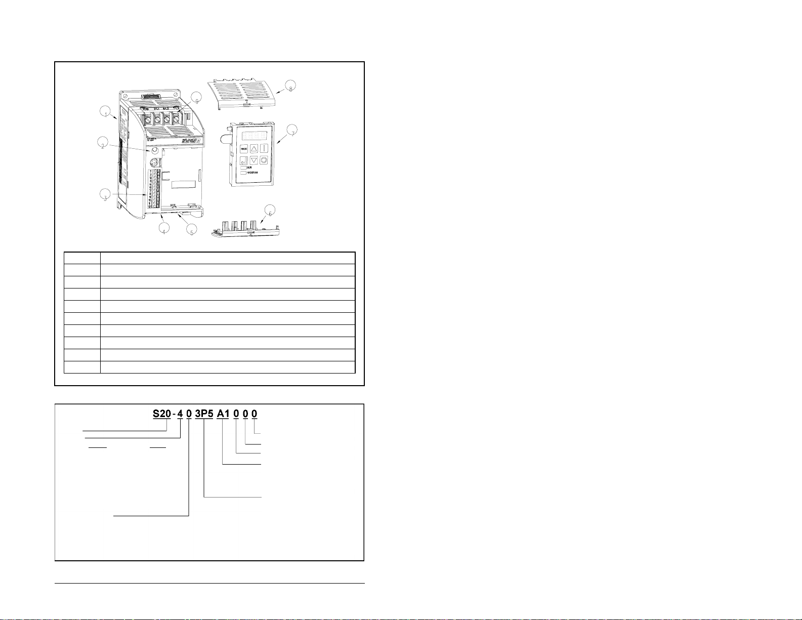
Drive Identification
Item Description
1 Nameplate
2 OK (green) / Fault (red) LED
3 Control Signal Ter m inal Block
4 Motor Output Terminal Block
5Fan
6 Bottom Finger Guard
7 Optional Local Keypad
8 Top Finger Guard
9 AC Input Power Terminal Block
SP200 AC Drive Components
S20 4
SP200
Voltage
Input
2 = 200-240 V, 3-phase; 230 V, 3-phase
4 = 380-480 V, 3-phase; 460 V, 3-phase
X = Selectable:
100-120 V, 1-phase; 230 V, 3-phase
or
200-240 V, 1-phase; 230 V, 3-phase
Y = 200-240 V, 1-phase; 230 V, 3-phase
Enclosure Type
0 = Protected chassis
Drive Identification
Output
Model Number Structure
-
0 3P5 A1 0
0 0
(Reserved - not used)
(Reserved - not used)
(Reserved - not used)
Model (Control Type)
A1 = Single Channel Analog
B1 = Preset Speed
C1 = Dual Channel Analog
Output Current (Horsepower)
1P3 = 1.3 A (0.5 HP)
2P0 = 2.0 A (1.0 HP)
2P3 = 2.3 A (0.5 HP)
3P5 = 3.5 A (2.0 HP)
4P2 = 4.2 A (1.0 HP)
6P0 = 6.0 A (1.5 HP)
7P0 = 7.0 A (2.0 HP)
1
Page 12

Technical Specifications
AC Input
Voltage
100-120,
1-phase
200-240,
1-phase
200-240,
3-phase
380-460,
3-phase
1
The input voltage range has a tolerance of ±10%, 47 to 63 Hz.
2
Recommended fuse type: UL Class J or CC, 600 V, time delay.
3
Device must meet UL 489 for UL purposes.
AC
Output
1
Voltage HP
230,
3-phase
230,
3-phase
230,
3-phase
460,
3-phase
0.5
1.0
1.5
0.5
1.0
1.5
2.0
0.5
1.0
2.0
0.5
1.0
2.0
Input
Current
(Amps)
9.4
17.2
24.6
4.7
8.6
12.3
14.3
2.7
5.0
8.3
1.5
2.4
4.1
Output
Current
(Amps)
2.3
4.2
6.0
2.3
4.2
6.0
7.0
2.3
4.2
7.0
1.3
2.0
3.5
Fuse
Rating
(Amps)
15 or 16
30
40
10
15 or 16
20
25
6
10
15 or 16
3 or 4
6
10
2
Control Inputs
• Rated voltage: 10 VDC to 24 VDC (±10%)
• Load (each): 10 mA minimum, 20 mA maximum
• Maximum allowable off-state leakage current: 1.5 V / 2.0 mA
Speed Reference Input
• Analog input impedance: 0 to 10 V: ≥100 kΩ
4 to 20 mA input: ~250 Ω
Circuit
Breaker
Rating
15
30
40
10
15
20
25
15
Typical
Power
3
Loss (W)
(A)
25
45
70
25
45
70
75
5
7
25
40
70
3
4
7
25
30
50
Relay Output
• Rated current and voltage: 0.5 A maximum at 125 VAC
1.0 A maximum at 30 VDC
Operating Performance
• Input frequency resolution: 0.4% analog, 0.1 Hz digital
• Output frequency resolution: 0.1%
• Output voltage regulation: 3%
• Power dip control ride through time: 100 msec minimum
Ambient Conditions
°
• Operating temperature: 0 to 50
• Storage temperature: -40
C (32° F to 122° F)
°
C to 85° C (-40° F to 185° F)
• Humidity: 0 to 95% non-condensing
• Elevation: 1000 meters (3300 ft) maximum without derating. For every 91.4 meters
(300 ft) above 1000 meters, derate the current by 1%. Above 3000 meters,
(10,000 ft), consult your Reliance Electric Sales Office.
2
SP200 AC Drive Quick Start Guide
Page 13
Standards and Approvals
• UL508C
• CSA22.2
• EN50178, EN60204-1 for Low Voltage Directive
• EN50081-1, EN50082-2, parts of EN61800-3 for EMC
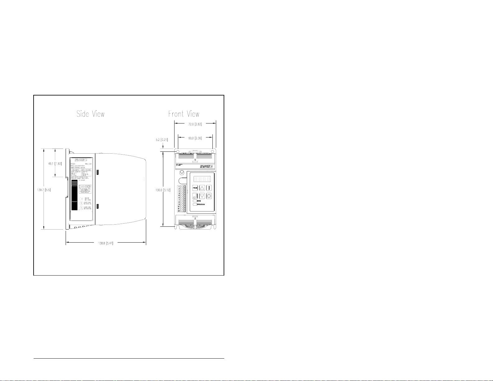
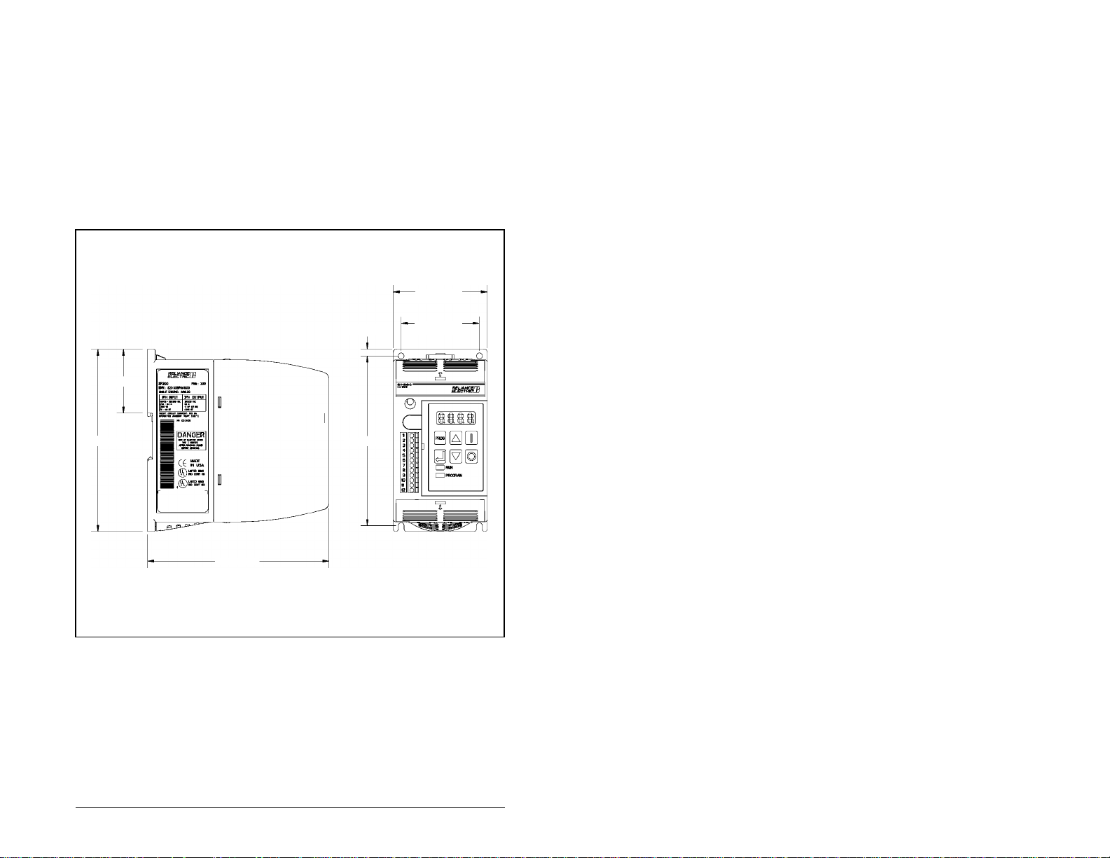
Mounting and Clearanc e Dimensions
• Top and bottom clearance is 38.1 mm [1.5 in].
• Side clearance is 25.4 mm [1.0 in] on the right if installation/removal of the
keypad is required.
Mounting and Clearance Dimensions
3
Page 14

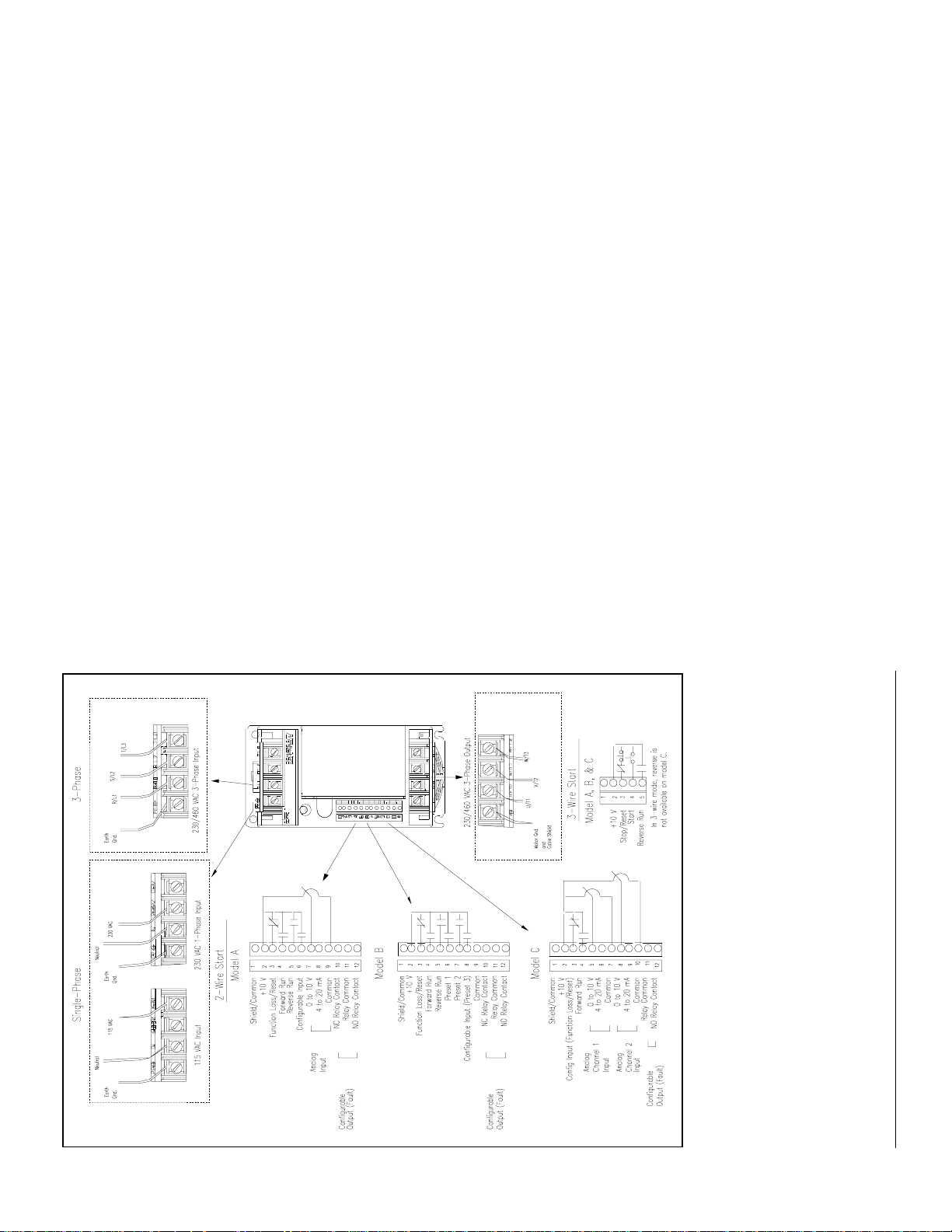
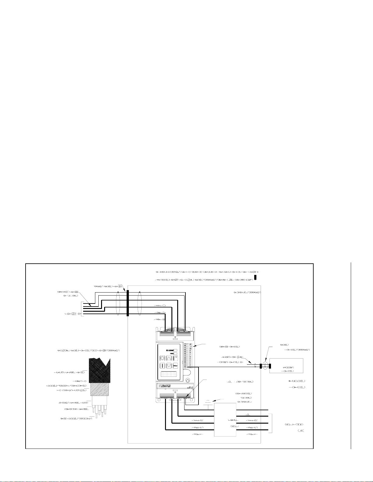
Wiring AC Power and Control Terminals
The following Attention statements apply to the wiring diagram on the facing page:
ATTENTION: This equipment is at line voltage when AC power is
connected. Disconnect and lockout all ung rounded conductors of the
AC power line before working on the unit. Failure to observe this
!
precaution could result in severe bodily injury or loss of life.
ATTENTION: Many local and national electrical codes require that an
input disconnect be provided in the incoming power lines. Failure to
observe this precaution could result in severe bodily injury or loss of
life.
ATTENTION: Many local and national electrical codes require that
upstream branch protection be provided to protect input power wiring.
Failure to observe this precaution could result in severe bodily injury
or loss of life.
ATTENTION: If the distribution system capacity exceeds the drive’s
maximum symmetrical fault short-circuit current of 100,000 amps,
additional impedance must be added to the AC line supplying the drive
to limit available current in the event of a fault. F ail ure to observe this
precaution could result in damage to, or destruction of, the equi pment.
AT TENTION:The user must provide an external, hardwired
emergency stop circuit outside of the SP200 drive circuitry . This circuit
must disable the system in case of improper operation. Uncontrolled
machine operation may result if this procedure is not followed.F ailure
to observe this precaution could result in severe bodily injury or loss
of life.
ATTENTION: If 2-wire control is selected, the drive will immediately
run when powered up in the presence of a forward or rev erse run
command. Failure to observe this precaution could result in severe
bodily injury or loss of life.
ATTENTION: The 4-pin circular connector (located directly above the
control terminals) may increase to a hazardous voltage level if the
control shield terminal (terminal 1) is left ungrounded. Failure to
observe this precaution could result in severe bodily injury or loss of
life.
4
SP200 AC Drive Quick Start Guide
Page 15
5
(16 AWG) wire.
2
(12 AWG) wire.
2
(26 AWG) to 1.5 mm
2
Power Terminal Information
• The terminal blocks accept up to 4 mm
• The recommended tightening torque is 1.35 Nm (12 in-lb).
Control Terminal Information
• The terminal block is isolated from input power.
• Control wires should be shielded and routed separately from the power wires.
• The terminal block accepts 0.14 mm
• The maximum control wire length is 30 meters (100 ft).
Wiring AC Power and Control Terminals
Page 16

Motor Cable Recommendations
Drive-to-Motor Cable Distance
The cable distance between the drive and motor is limited f or t he f oll owing tw o reasons:
1. Long drive-to-motor cables can produce peak voltages that can damage motors
having an electrical insulation system less than that of MG-1 (1600 V). The use of
output line reactors can affect the limit. Use the table on the following page to
determine the maximum distance that may be applied with a non MG-1 motor (for
example, a motor with an insulation of 1000 V peak).
2. Long drive-to-motor cables also produce current that is capacitively coupled to
ground. This can cause the drive to fault and misrepresent the cause. The use of
output line reactors and cable shields or conduit can affect the limit. Use the table
on the followi ng page to det ermine the maximum distance under which the SP200
drive may be applied.
Both of the limitations described above must be considered for your installation. The
smaller of these two numbers will dictate your final limit.
Drive-to-Motor Wire Type
The type of wire that is recommended to be used between the drive and motor is
dependent on the environment in which it is used. The use of wire with PVC (PolyVinyl
Chloride) insulation is restricted to certain conditions. A common example of this wire
type is THHN. In these conditions where PVC is not recommended, XLPE (Cross
Linked PolyEth y lene) is recommended. An example of this wire type is XHHW-2. The
action of pulling wire through 90° bends in conduit removes some of the wire’s
insulation. For this reason, extra care should be taken during this process and a wire
with above average insulation thickness should be chosen.
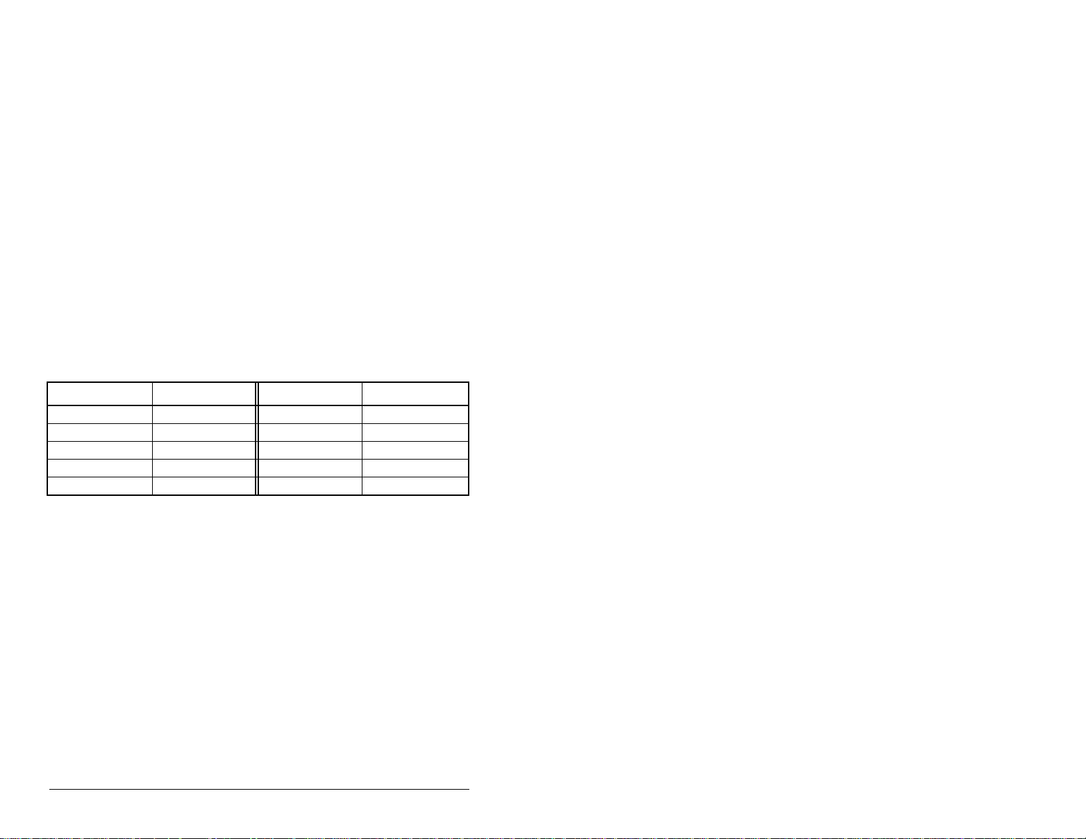
Recommended Wire Type(s)
Condition
Dry
Wet XLPE XHHW-2
1
When using wire with PVC type insulation, standard 15mil thickness is adequate
under normal conditions; however, when multiple motor’s wires are run in the same
conduit for more than 50 ft (15m), and the voltage is greater than 240V + 10%, 20 mil
or greater thickness is recommended.
6
Insulation Type(s) Example(s)
PVC
XLPE
1
THHN
XHHW-2
SP200 AC Drive Quick Start Guide
Page 17
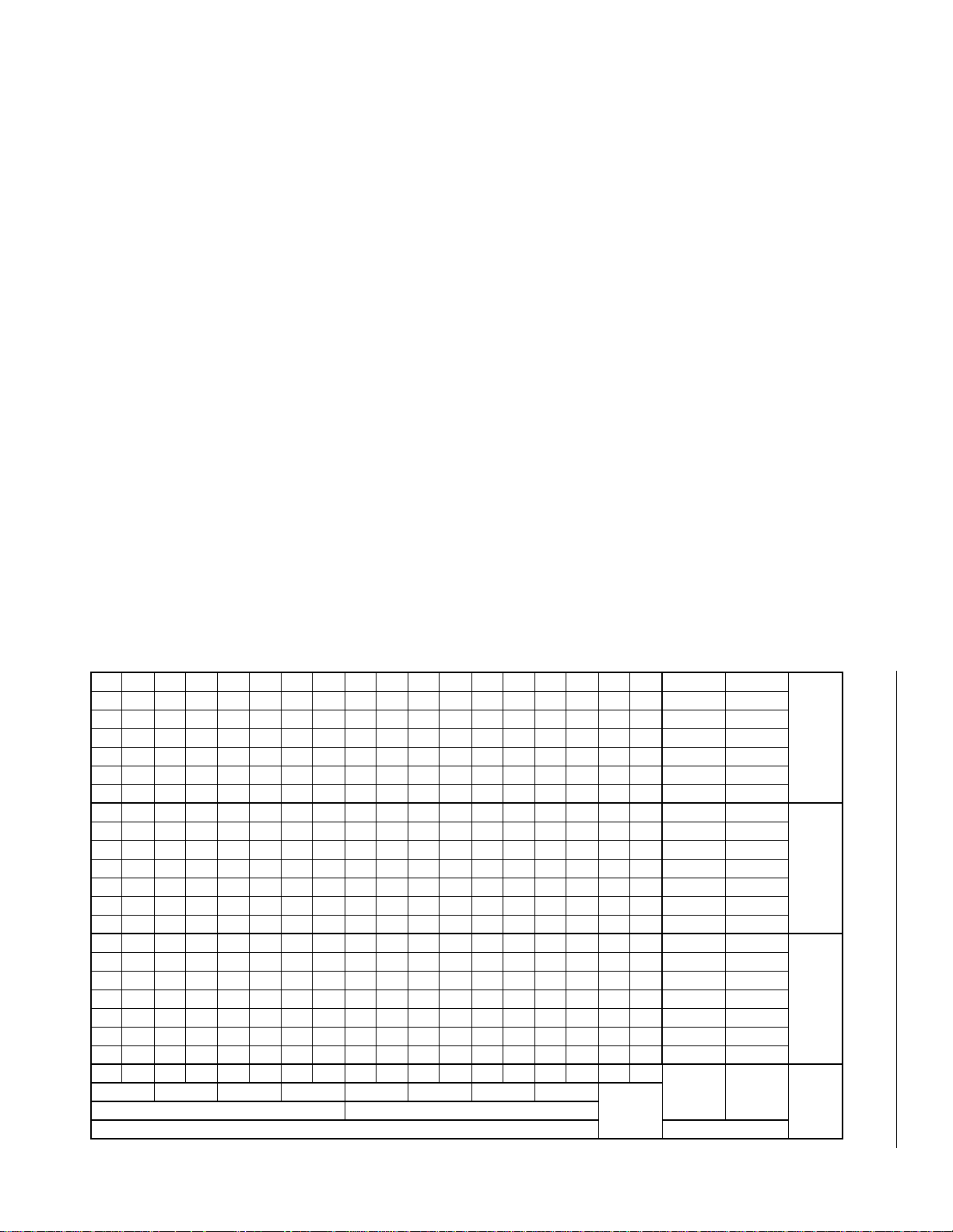
460 2.0 (1.5) 300 91 200 61 200 61 200 61 170 52 400 122 400 122 400 122 400 122
460 1.0 (0.75) 300 91 120 37 100 30 100 30 100 30 300 91 300 91 300 91 300 91
460 0.5 (0.37) 300 91 100 30 100 30 100 30 90 27 175 53 175 53 175 53 150 46
240 2.0 (1.5) — — 600 183 600 183 500 152 300 91 600 183 600 183 600 183 60 0 183
120 / 240 1.5 (1.1) — — 600 183 600 183 500 152 300 91 600 183 600 183 600 183 600 183
120 / 240 1.0 (0.75) — — 600 183 600 183 500 152 400 122 600 183 600 183 600 183 600 183
120 / 240 0.5 (0.37) — — 300 91 280 85 280 85 280 85 600 183 600 183 600 183 600 183
460 2.0 (1.5) 80 24 220 67 200 61 170 52 130 40 600 183 600 183 600 183 200 183
460 1.0 (0.75) 40 12 180 55 140 43 100 30 100 30 600 183 600 183 600 18 3 400 122
460 0.5 (0.37) 15 5 120 37 100 30 100 30 90 27 200 61 200 61 200 61 150 46
240 2.0 (1.5) — — 600 183 400 122 300 91 200 61 600 183 600 183 600 183 600 183
120 / 240 1.5 (1.1) — — 600 183 400 122 300 91 200 61 600 183 600 183 600 183 600 183
120 / 240 1.0 (0.75) — — 500 152 300 91 300 91 200 61 600 183 600 183 600 183 600 183
120 / 240 0.5 (0.37) — — 400 122 300 91 300 91 100 30 600 183 600 183 600 183 600 183
460 2.0 (1.5) 20 6 220 67 180 55 180 55 100 30 400 122 400 122 400 122 400 122
460 1.0 (0.75) 25 8 120 37 100 30 100 30 100 30 300 91 300 91 300 91 300 91
460 0.5 (0.37) 50 15 100 30 100 30 100 30 90 27 175 53 175 53 175 53 150 46
240 2.0 (1.5) — — 600 183 600 183 500 152 300 91 600 183 600 183 600 183 600 183
120 / 240 1.5 (1.1) — — 600 183 600 183 500 152 300 91 600 183 600 183 600 183 600 183
120 / 240 1.0 (0.75) — — 500 152 500 152 400 122 300 91 600 183 600 183 600 183 600 183
ft m ft m ft m ft m ft m ft m ft m ft m ft m
2 kHz 4 kHz 6 kHz 8 kHz 2 kHz 4 kHz 6 kHz 8 kHz
Shielded Cable or Wires in Conduit Unshielded Cable
SP200 Drive Limit
Limit
Motor
1000 V
Volts HP (kW)
Input
Drive Rating
Motor
3 % at
Drive
3 % at
None 120 / 240 0.5 (0.37) — — 250 76 250 76 250 76 200 61 600 183 600 183 600 183 600 183
Reactor
7
Motor Cable Recommendations
Page 18
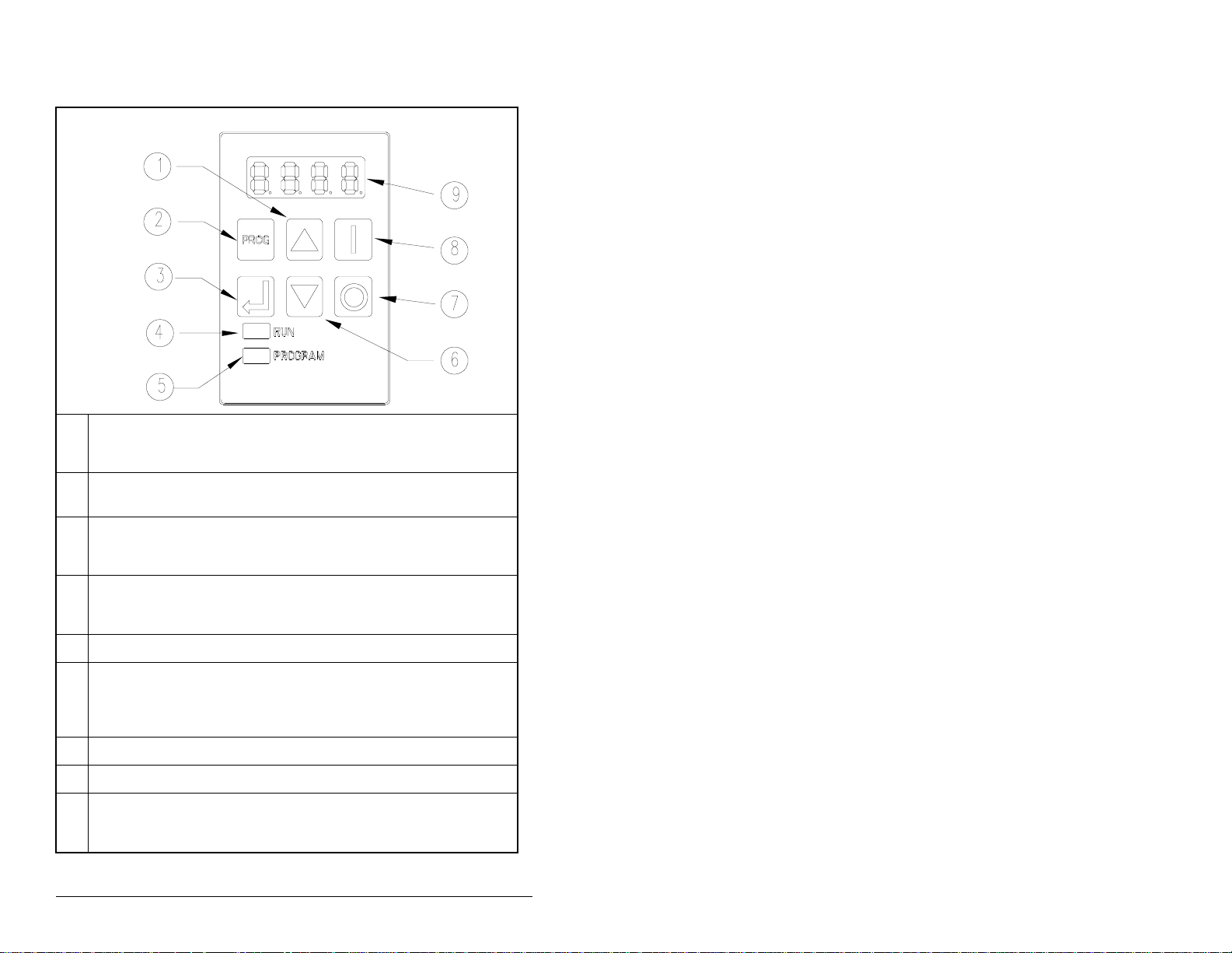
Local Keypad Operation
1 In display mode, the UP ARROW key increments the local speed reference.
In program mode, this key increments the parameter number or parameter
value.
2 The PROGRAM key toggles between display and program modes. The
PROGRAM LED (5) turns on when the drive is in program mode.
3 In display mode, the ENTER key increments to the next display parameter.
In program mode, this key toggles between the parameter number and
parameter value.
4 The RUN LED turns on when the drive is running in either the foward or
reverse direction. The RU N LED flashes while the drive is changing
direction.
5 The PROGRAM LED turns on when the drive is in program mode.
6 In display mode, the DOWN ARROW key decrements the local speed
reference.
In program mode, this ke y decrements the par ameter number or parameter
value.
7 The STOP key issues stop and fault rese t commands to the drive.
8 The START key issues start commands to the drive when P-10 = 1.
9 The display shows either a parameter number or a parameter value.
The parameter numbers are preceded by either a “P-” or a “d-”.
8
SP200 AC Drive Quick Start Guide
Page 19
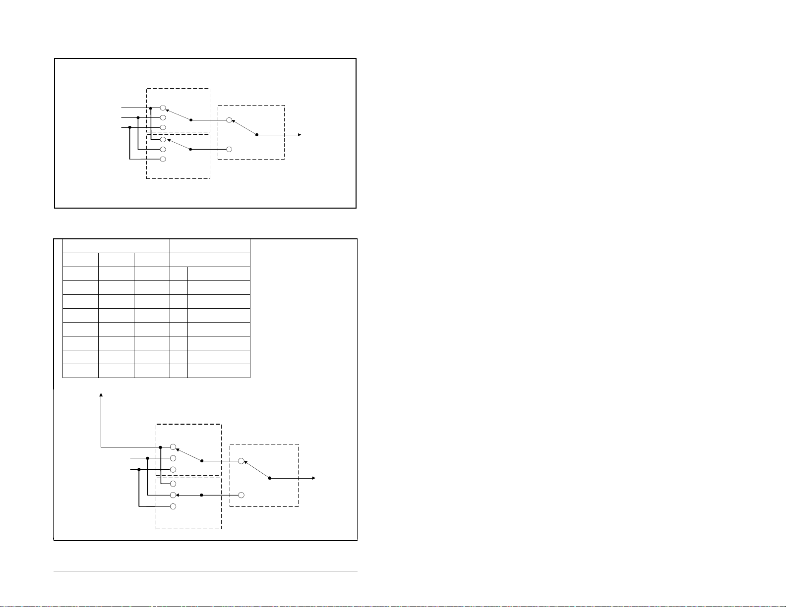
Selecting a Speed Reference
Main
Analog Input 1
Keypad Frequency
Internal Frequency
0
1
2
0
1
2
Speed Reference Source for Model A Drives
Input Terminal Status Resulting Speed
Term 8 Term 7 Term 6 Parameter
0 0 0 41 Preset Speed 1
0 0 1 42 Preset Speed 2
0 1 0 43 Preset Speed 3
0 1 1 44 Preset Speed 4
1 0 0 45 Preset Speed 5
1 0 1 46 Preset Speed 6
1 1 0 47 Preset Speed 7
1 1 1 48 Preset Speed 8
Speed
Ref
(P-20)
Alternate
Speed
Ref
(P-21)
Configurable
Input
(P-11 = 3)
Speed
Reference
Keypad Frequency
Internal Frequency
Speed Reference Source for Model B Drives
Selecting a Speed Reference
Main
0
1
2
0
1
2
Speed
Ref
(P-20)
Alternate
Speed
Ref
(P-21)
Configurable
Input
(P-11 = 3)
Speed
Reference
9
Page 20
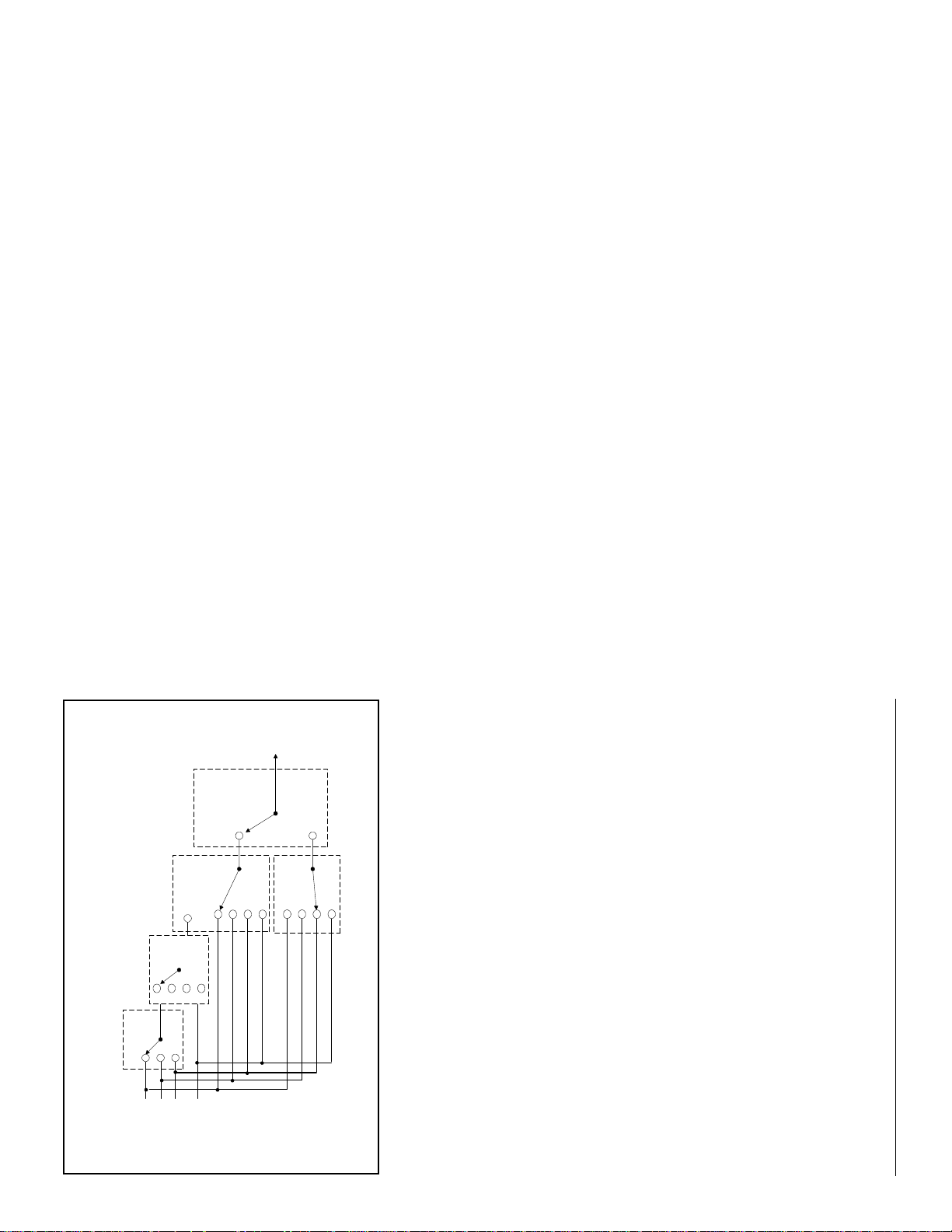
Process
0
Select
(P-28)
Process Ref
1
0
Main
4
(P-29)
Operation
2
1
2
Ref
Speed
0
3
(P-20)
1
Speed
Input
(P-11 = 3)
Configurable
2
3
Reference
Ref
Speed
Alternate
0
1
(P-21)
2
SP200 AC Drive Quick Start Guide
3
Speed Reference Source for Model C Drives
Analog Input 1
Internal Frequency
Keypad Frequency
Analog Input 2
10
Page 21
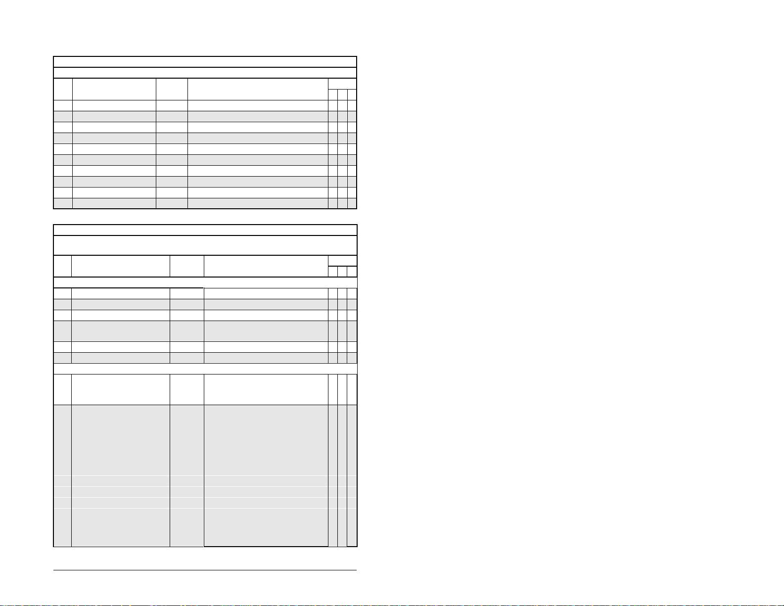
Drive Parameters
Display Parameters
(Read Only)
Units / Model
No. Name Default Range A B C
d-00 Command Frequency 0.1 Hz 0 - 240.0 x x x
d-01 Output Frequency 0.1 Hz 0 - 240.0 x x x
d-02 Output Current 0.1 A 0 - 200 (% of rated current) x x x
d-03 Bus Voltage 1 V 0 - 1000 x x x
d-04 Fault Code Annn alphanumeric code x x x
d-05 Input Status decimal 0000 - 7111 x x x
d-06 Drive Rating decimal x x x
d-07 Firmware Version Annn alphanumeric code x x x
d-08 Analog Input 1 Units 0.1 % 0 - 110.0 x x
d-09 Analog Input 2 Units 0.1 % 0 - 110.0 x
Program Parameters
(Parameters that can be programmed only while the drive
No. Name Default Range A B C
Group 0: Protection
P-00Minimum Speed * 0 Hz 0 - Maximum Speed x x x
P-01Maximum Speed * 60 Hz Minimum Speed - 240 x x x
P-02Motor Overload Current x.x A 20% - 200% of drive’s rated current x x x
P-03Reverse Disable * 0 0 = reverse enabled
P-04 Auto Restart Attempts 0 0 - 10 x x x
P-05Current Limit 150 % 10% - 150% of drive’s rated current x x x
Group 1: Digital Input / Output
P-10Start Control * 2 1 = keypad control
P-11Configurable Input * 2 (A) 0 = function loss (P-10 ≠ 3) x
is stopped are indicated by an asterisk *)
Units / Model
1 = reverse disabled
2 = 2-wire control
3 = 3-wire control
1 (B) 1 = disabled x
0 (C) 1 = preset x
1 = reverse run (2-wire) x
2 = jog (P-10 ≠ 1)
2 = jog (P-10 ≠ 1 or 3)
3 = alternate spd ref select x x
3 = alt spd ref select (P-10 ≠ 3) x
4 = n.c. coast-to-stop x x
4 = n.c. coast-to-stop (P-10 ≠ 3)
5 = secondary accel/decel x x
5 = sec accel/decel (P-10 ≠ 3)
x x x
x
x
x
x
x
x
x x
x
x
x
x
x
x
Drive Parameters
11
Page 22
x
x
xxx
xxx
x
x
x
xxx
xxx
x
x
x
x
xxx
x
x
x
x
xxx
xxx
xxx
SP200 AC Drive Quick Start Guide
analog input 2
output
1 = no fault/auto restarting x x x
2 = run x x x
3 = at frequency x x x
4 = above frequency x x x
5 = above current x x x
0 = preset speeds
1 = keypad
2 = Internal / Jog Frequency (P-40)
3 = analog input 2
4 = Process Operation (P-29)
0 = preset speeds
1 = keypad
2 = Internal / Jog Frequency (P-40)
3 = analog input 2
1 = keypad
2 = Internal / Jog Frequency (P-40)
and analog input 2
1 = multiply Process Ref (P-28)
2 = PI control
3 = inverted PI control
1 = coast-to-rest
2 = DC injection
Program Parameters
Units / Model
is stopped are indicated by an asterisk *)
(Parameters that can be programmed only while the drive
Deceleration Time 1 5.0 sec 0 - 600.0 x x x
Deceleration Time 2 10.0 sec 0 - 600.0 x x x
No. Name Default Range A B C
P-12 Configurable Output 0 0 = no fault x x x
P-13Configurable Output Level 0.0 0 - 999.9 (only when P-12 = 4 or 5) x x x
Group 2: Speed Reference
P-20Main Speed Reference 0 0 = analog input 1
P-21Alternate Speed Reference 1 0 = analog input 1
P-23Analog Input 1 Gain 100.0 % 0 - 110.0 x x
P-25Analog Input 2 Gain 100.0 % 0 - 110.0 x
P-22Analog Input 1 Offset 0.0 % 0 - 110.0 x x
P-24Analog Input 2 Offset 0.0 % 0 - 110.0 x
P-27Process Integral Gain 0.00 0 - 10.0 (0 = off) x
P-26Process Proportional Gain 0.00 0 - 10.0 (0 = off) x
P-28Process Reference 0 0 = analog input 1
P-29Process Operation 0 0 = add Process Ref (P-28) and
Group 3: Dynamic Control
P-30Acceleration Time 1 5.0 sec 0 - 600.0 x x x
P-31
P-32Acceleration Time 2 10.0 sec 0 - 600.0 x x x
P-33
P-34Stop Control 0 0 = ramp-to-rest
DC Brake Current 50 % 10 - 150 x x x
P-35
P-36DC Brake Time at Stop 0.5 sec 0 - 20.0 x x x
12
Page 23

13
x x x
xxx
x x
0 - 230 or 0 - 460 x x x
Group 5: V / Hz
460 V
P-50Base Voltage 230 V /
P-51Base Frequency 60 Hz 0 - 240 x x x
P-53Breakpoint Frequency 0 Hz 0 - 240 x x x
P-52Breakpoint Voltage 0 V 0 - 230 or 0 - 460 x x x
P-55Auto Torque Boost 3.0 % 0 - 10 x x x
P-54Boost Voltage 11 / 23 V 0 - 46 or 0 - 92 x x x
Group 6: Utility
Program Parameters
Units / Model
is stopped are indicated by an asterisk *)
(Parameters that can be programmed only while the drive
No. Name Default Range A B C
P-37Avoidance Frequency 0.0 Hz 0 - 240.0 x x x
P-38Avoidance Frequency Band 0.0 Hz 0 - 30.0 x x x
Group 4: Fixed Speeds
P-41Preset Speed 1 2.5 Hz 0 - 240.0 x
P-42Preset Speed 2 5.0 Hz 0 - 240.0 x
P-43Preset Speed 3 10.0 Hz 0 - 240.0 x
P-44Preset Speed 4 20.0 Hz 0 - 240.0 x
P-45Preset Speed 5 30.0 Hz 0 - 240.0 x
P-46Preset Speed 6 40.0 Hz 0 - 240.0 x
P-47Preset Speed 7 50.0 Hz 0 - 240.0 x
P-40Internal / Jog Frequency 60.0 Hz 0 - 240.0 x x x
P-48Preset Speed 8 60.0 Hz 0 - 240.0 x
P-61Program Password OFF OFF / ON ; entering 257 toggles
P-60Reset to Defaults * 0 0 - 1; entering 1 performs a reset x x x
the setting
displays
displays
P-63Units at Analog Max 0 0 - 9999; scales d-08 and d-09
P-62Units at Base Frequency 0 0 - 9999; scales d-00 and d-01
P-64Carrier Frequency 2 kHz 2 - 8 x x x
Drive Parameters
Page 24
Compliance with EU Requirements
The SP200 drive is CE-marked for Low Voltage (LV) Directive 73/23/EEC and all
applicable standards when installed as described within the Low Voltage section that
follows. It also has been tested to meet Electromagnetic Compatibility (EMC) Directive
89/336/EEC when installed as described within the Electromagnetic Compatibility
section that follows. Contact the Rockwell AutoFax service in the United States at
216-646-7777 (or your local Rockwell A utomation office if out side the U .S.) for copies of
the Declaration of Conformity (DOC).
Conformity of the SP200 drive to EU directives does not guarantee that the entire
system will conform. For EMC, many other factors can affect the total installation, and
only direct measurements can verify total conformity. It is the responsibility of the
machine manufacturer (or end user, if the machine is being modified or used beyond
manufacturer’s specifications) to comply.
Low Voltage Directive 72/23/EEC
• Follow all general precautions and ATTENTION statements throughout this manual.
• Provide an earth ground connection to the PE terminal.
• Install in a protective enclosure which restricts access to IP 20 rated devices as
required by your national and local codes and regulatory agencies.
Electromagnetic Compatibility Directive 89/336/EEC
• Install the SP200 drive and Input Mains Filter (see the table below) in a t ypical IEC or
NEMA metal (shielded) enclosure as shown in the figure on the following page.
Adhere to maximum motor cable lengths as specified on page 7 (≤ 25 m).
Drive Model
Number
S20-X02P3..... S20-MF1-Y014 S20-204P2..... S20-MF1-45P0
S20-X04P2..... S20-MF1-Y014 S20-207P0..... S20-MF1-49P5
S20-X06P0..... S20-MF1-Y014 S20-401P3..... S20-MF1-45P0
S20-Y07P0..... S20-MF1-Y014 S20-402P0..... S20-MF1-45P0
S20-202P3..... S20-MF1-45P0 S20-402P3..... S20-MF1-45P0
Refer to
• Keep all input power , output po wer , and control signal wiring, both inside and outside
enclosure, physically separate from one another.
SP200 Mains Filters
Filter Model Number
(D2-3420) for filter dimensions and weights.
• Connect the enclosure to the SP200 PE input (top) terminal.
• Connect the enclosure to earth ground.
• Use shielded cable with a ground conductor or individual conductors in grounded
metal conduit for motor power wiring on the output side of the drive, both inside and
outside the enclosure, all the way to the motor. Bring the shield as close to the output
power terminals as possible. Connect the motor cable ground and shield to the
ground terminal on the output (bottom) side of the SP200 drive. Connect the
opposite end of the motor cable ground conductor and shield to the motor housing.
• Use shielded cable or grounded metal conduit for control wiring both inside and
outside the enclosure, all the way to the control source. Bring the shield as close to
the control terminals as possible. Connect the shield to the SP200 shield/common
(terminal 1) and to the PE terminal on the input side (top) of the SP200 drive. Also
connect the opposite end of the shield to the common of the device that is controlling
the SP200 drive.
• Use EMC-tested 360 degree cable clamps to connect the motor and control shields
to the enclosure cable exit point(s) and to the motor housing. Contact points must be
clean and free of paint or nonconductive coating.
• Make certain all ground connections provide a low impedance path for high
frequency signals.
Drive Model
Number
Filter Model Number
14
SP200 AC Drive Quick Start Guide
Page 25
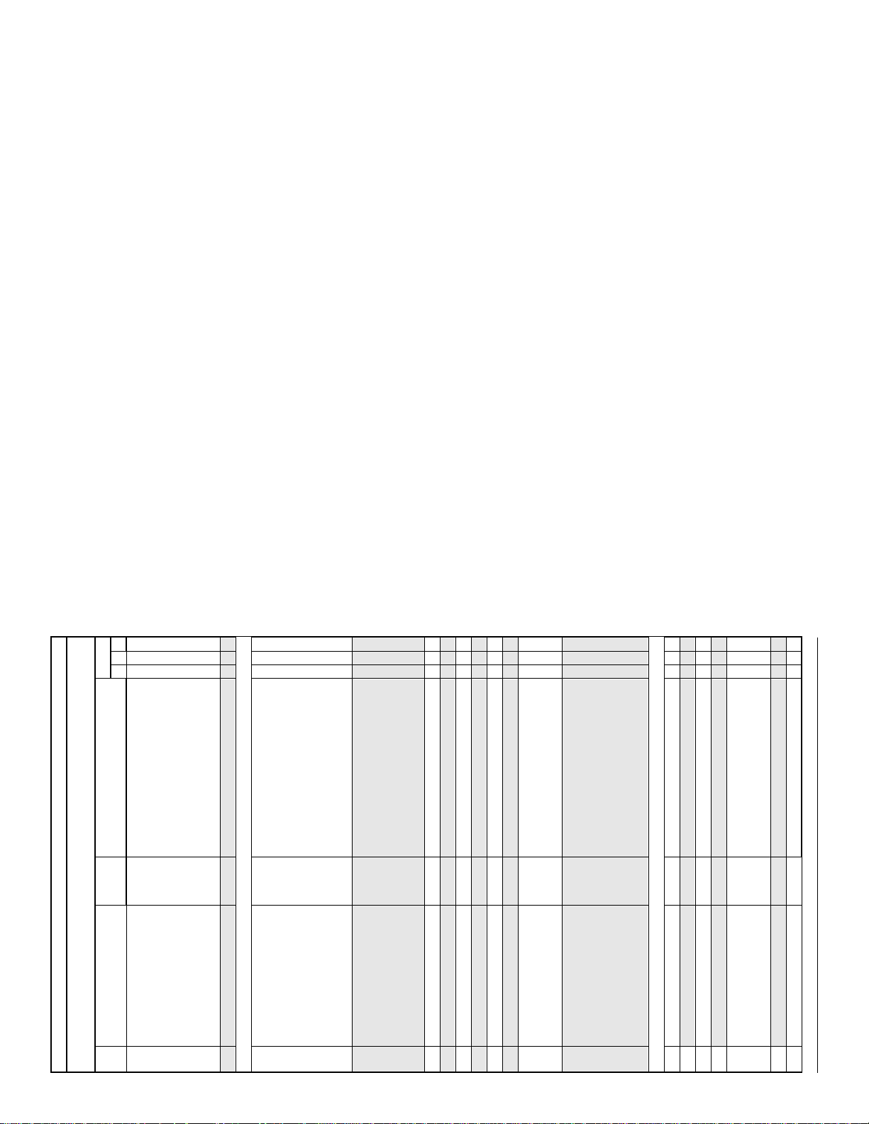
Grounding, Control, and Motor Connections
15
Compliance with EU Requirements
Page 26

Fault Codes and Troubleshooting
• If no fault condition exists , the LED will be green.
• If a fault condition exists, the LED will be continuously red when a local keypad is
connected, or flashing red when a local keypad is not connected.
• All faults can be reset by cycling the reset control input, pressing the stop key, or
cycling power, except as noted in Corrective Action in the table below.
Display
1
Number of
Fault LED
Code
Flashes
CF 2
FL 2
LU 3
HU 4
dO 5
OL 5
OH 6
OC 7
CL 8
UF 9
J1 10
J2 10
J3 10
J4 10
J5 10
J6 10
CH 11
UP 12
Auto Resettable
Fault
Description Fault Cause Corrective Action
Control Input Illegal control input
Function Loss Start attempt while
Under Voltage
Over Voltage1
Drive Overload
Motor Overload
Over
Temperature
Over Current1
(300%)
Bad Keypad
Connection
Negative Slope Con flicting parameter
Ground Short Phase U - Verify output wiring is correct
Phase to Phase
Short
Checksum Failure Parameter value out of
Microprocessor
Fault
sequence.
STOP (Function Loss)
input is off.
1
- Low input line.
- Temporary loss of
input line.
- High input line.
- Decel time too fast.
- Overhauling load.
1
Excessive driven load. Reduce the load.
1
Excessive driven load. - Verify P-02 is set correctly.
- Operating environment
1
is too hot.
- Fan is blocked or not
operating.
- Excessive driven load.
- Shaft rotation blocked.
- Excessive driven load.
- Output wiring is
incorrect or shorted.
Bad connection from
keypad to drive.
values.
Phase V
Phase W
Phase U - V - Verify output wiring is
Phase U - W
Phase V - W
range.
Internal processor error. Cycle power. If fault persists,
- 3-wire: Verify Start and Jog
inputs are not both ON.
- 2-wire: Verify that only one
input (Forward, Reverse, or
Jog) is on.
Verify STOP (Function Loss)
input is ON before attempting
to start drive.
Check input line to verify
voltage is within operating
specifications.
- Check input line to verify
voltage is within operating
specifications.
- Increase decel time.
- Reduce the load.
- Verify the ambi ent
temperature is < 50
- Verify clearance above/
below drive.
- Check for fan obstruction.
Replace fan if required.
- Reduce the carrier
frequency (P-64).
- Reduce the load.
- Check for obstructions to
shaft rotation or reduce
excessive load.
Increase accel / decel time.
-
- Verify output wiring is
correct.
Verify keypad is properly
connected to drive.
Adjust values of parameters P-50 through P-54.
- Verify output phase is not
grounded.
- Verify motor is not damaged.
correct.
- Verify motor is not damaged.
Load default parameter values
(P-60 =1), then cycle power. If
fault persists, replace drive.
replace drive.
°.
16
SP200 AC Drive Quick Start Guide
Page 27
Identification du variateur
Article Description
1 Plaque d'identification
2 Diode électroluminescente : O.K. (vert) / Faute (rouge)
3 Bornier de commande
4 Bornier de la sortie moteur
5 Ventilat eur
6 Cache de protection inférieur
7 Console de commande et de programmation option
8 Cache de protection supérieur
9 Bornier d'alimentation 20 ou 30 AC
Composants du variateur SP200
SP200
Tension
Entrée
2 = 200-240 V, triphasé ; 230 V, triphasé
4 = 380-480 V, triphasé ; 460 V, triphasé
X = 2 choix possibles :
100-120 V, monophasé ; 230 V, triphasé
ou
200-240 V, monophasé ; 230 V, triphasé
Y = 200-240 V, monophasé ; 230 V, triphasé
Type d’enceinte
0 = IP20
Sortie
Structure du numéro de modèle
Identification du variateur
(Réservé - non utilisé)
(Réservé - non utilisé)
(Réservé - non utilisé)
Modèle (ty pe de commande)
A1 = Analogique (1 entrée)
B1 = Vitesse préselectionnée
C1 = Analogique (2 entrées)
Courant de sortie
(kW)
1P3 = 1,3 A (0,37 kW)
2P0 = 2,0 A (0,75 kW)
2P3 = 2,3 A (0,37 kW)
3P5 = 3,5 A (1,5 kW)
4P2 = 4,2 A (0,75 kW)
6P0 = 6,0 A (1,1 kW)
7P0 = 7,0 A (1,5 kW)
1-f
Page 28

Spécifications techniques
2
disjoncteur
Cal.
(A)
15
30
40
10
15
20
25
5
7
15
3
4
7
Cal.
fusibles
(A)
15 ou 16
30
40
10
15 ou 16
20
25
6
10
15 ou 16
3 ou 4
6
10
1
Tension
sortie
CA CV
230,
triphasé
230,
triphasé
230,
triphasé
460,
triphasé
Tension
entrée CA
100-120,
monophasé
200-240,
monophasé
200-240,
triphasé
380-460,
triphasé
1
La plage des tensions d'entrée a une tolérance de ±10%, 47 à 63 Hz.
2
Type de fusible recommandé : UL classe J ou CC, 600 V, action retardée.
3
Le dispositif doit être conforme à la norme UL 489 pour les besoins UL.
0,5
1,0
1,5
0,5
1,0
1,5
2,0
0,5
1,0
2,0
0,5
1,0
2,0
Courant
entrée
(A)
9,4
17,2
24,6
4,7
8,6
12,3
14,3
2,7
5,0
8,3
1,5
2,4
4,1
Courant
sortie
(A)
2,3
4,2
6,0
2,3
4,2
6,0
7,0
2,3
4,2
7,0
1,3
2,0
3,5
Signaux de commande (entrées)
• Tension nominale : 10 Vcc à 24 Vcc (±10%)
• Charge (chacune) : 10 mA minimum, 20 mA maximum
• Courant de fuite maximum permissible à l'état bloqué : 1,5 V / 2,0 mA
Consigne de vitesse
• Impédance d'entrée analogique : 0 à 10 V : ≥ 100 Ω
4 à 20 mA : ~250 Ω
Sortie relais
• Courant et tension nominaux : 0,5 A maximum sous 125 Vca
1,0 A maximum sous 30 Vcc
Dissi-
3
pation
(W)
25
45
70
25
45
70
75
25
40
70
25
30
50
Performances
• Résolution fréquence d'entrée : analogique 0,4%, numérique 0,1 Hz
• Résolution fréquence de sortie : 0,1%
• Contrôle tension de sortie : 3%
• Durée des intervalles entre chutes de tension : 100 ms minimum
Conditions ambiantes
• Température de serv ice : 0 à 50° C (32° F à 122° F)
• Température de stockage : -40° C à 85° C (-40° F à 185° F)
• Humidité : 0 à 95%, sans condensation
• Altitude : 1 000 mètres (3 300 pieds) maximum sans de’classement. Pour chaque
incrément de 91,4 mètres (300 pieds) au-dessus de 1 000 mètres, réduire le courant
nominal de 1%. Au-dessus de 3 000 mètres (10 000 pieds), consulter le service
commercial de Reliance Electric.
2-f
Guide de mise en route du variateur SP200
Page 29
Normes et agréments
• UL508C
• CSA22.2
• EN50178, EN60204-1 relativement à la Directive basse tension
• EN50081-1, EN50082-2, parties de EN61800-3 pour les compatibilités
électromagnétiques
Montage et côtes d'enco mb re men t
Vue latérale
49,1 [1,93]
139,7 [5,5]
138,8 [5,47]
Vue de face
5,2 [0,21]
130,0 [5,12]
72,0 [2,83]
60,0 [2,36]
• Espacement en haut et en bas de 38,1 mm [1,5 po.].
• Espacement latéral de 25,4 mm [1,0 po.] sur la droite si l'installation ou le retrait
de la console de programmation est nécessaire.
Montage et côtes d'encombrement
3-f
Page 30

Câblage des borniers d'alimentation en
courant alternatif (CA) et de commande
Les avertissements suivants s'appliquent au schéma de câblage de la page opposée :
ATTENTION : Cet équipement contient des potentiels élevés lorsque
l'alimentation CA est connectée. Débrancher et isoler tous les
conducteurs de l'alimentation CA non mis à la terre avant d'entre-
!
prendre un travail sur le variateur. Tout défaut d'observation de ces
précautions peut entraîner de graves dommages corporels ou même
la mort.
ATTENTION : De nombreux codes locaux et nationaux exigent qu'un
interrupteur général soit installé sur l’alimentation secteur avant la
distribution au variateur. Tout défaut d'observation de ces précautions peut entraîner de graves dommages corporels ou même la mort.
ATTENTION : De nombreux codes locaux et nationaux exigent
qu'une protection en amont sur les phases soit fournie pour protéger
l'alimentation du variateur. Tout défaut d'observation de ces précautions peut entraîner de grav es dommages corporels ou même la mort.
ATTENTION : Si la capacité du système de distribution dépasse
l'intensité maximale du courant de court-circuit à défaut symétrique
du variateur, (100 kA), il faut ajouter un l'impédance sur la ligne de
courant alternatif alimentant le variateur pour limiter le courant
disponible en cas de défaut. Tout défaut d'observation de ces
précautions peut entraîner des dégâts matériels ou la destruction
de l'équipement.
ATTENTION : L'utilisateur doit fournir un circuit d'arrêt d'urgence
externe et câblé en dehors des circuits du variateur SP200. Ce circuit
doit pouvoir désactiver le système en cas de fonctionnement anormal.
Un fonctionnement incontrôlé de la machine pourrait survenir si
l’installation d’un tel circuit n’est pas effectuée. Tout défaut d'observation de ces précautions peut entraîner de graves dommages corporels
ou même la mort.
ATTENTION : Si une commande à deux fils est choisie, le variateur
se met immédiatement en marche lorsqu'il est mis sous tension en
présence d'une commande de marche avant ou de marche arrière.
T out défaut d'observation de ces précautions peut entraîner de graves
dommages corporels ou même la mor t .
ATTENTION : La tension du connecteur circulaire à quatre broches
(situé directement au-dessus des borniers de la commande) peut
atteindre un niveau dangereux si la borne de blindage du variateur
(borne 1) n'est pas mise à la masse. Tout déf aut d'observation de ces
précautions peut entraîner de graves dommages corporels ou même
la mort.
4-f
Guide de mise en route du variateur SP200
Page 31

Alimentation triphasée
Alimentation monophasée
5-f
(16 AWG).
2
En mode trois fils, la marche
arrière n'est pas disponible
Entrée 230/460 Vca triphasée
Mise à
la terre
230 Vca
Neutre
Mise à
la terre
115 Vca
Neutre
Mise à la
terre
Entrée monophasée 230 Vca
Modèle A
+10 V
Démarrage deux fils
Blindage/commun
Entrée 115 Vca
0 à 10 V
Commun
4 à 20 mA
Marche avant
Marche arrière
Entrée configu rable
Dévalidation/réinitialisation
Entrée
analogique
Modèle B
Relais NF
Relais NO
Commun relais
Sortie conf ig ur abl e
(défaut)
+10 V
Blindage/commun
Dévalidation/réinitialisation
Sortie 230/460 Vca triphasée
Mise à la terre
moteur et blindag e de
câble
Modèle C
Commun
Relais NF
Marche avant
Marche arrière
Entrée vit présel 1
Entrée vit présel 2
Relais NO
Commun relais
Entrée configurable (réglage 3)
Sortie configurable
(défaut)
+10 V
Blindage/commun
+10 V
Modèles A, B et C
Démarrage trois fils
Arrêt/réinitialisation
0 à 10 V
0 à 10 V
Commun
4 à 20 mA
Marche avan t
Entrée
analogique
canal 1
Entrée
analogique
Config. entrée (Dévalidation/réinitialisation)
sur le modèle C.
Démarrage
Marche arrière
Commun
4 à 20 mA
Relais NO
Commun relais
canal 2
Sortie configurable
(défaut)
(12 AWG).
2
(26 AWG) à 1,5 mm
2
Renseignements concernant les borniers de l'alimentation électrique
indépendamment des fils de l'alimentation électrique.
• Les borniers acceptent des fils de calibre jusqu'à 4 mm
• Le couple de serrage recommandé est de 1,35 Nm (12 po.-livre).
Renseignements concernant le bornier de la commande
• Le bornier est isolé de l'alimentation d'entrée.
• Les fils de la commande doivent être blindés et acheminés séparément,
• Le bornier accepte des fils de calibre de 0,14 mm
Câblage des borniers d'alimentation en courant alternatif (CA) et de commande
• La longueur maximum du câble de la commande est de 30 mètres (100 pieds).
Page 32

Recommandations au sujet du câble
de moteur
Distance de câble entre le variateur et le moteur
La distance de câble entre le variateur et le moteur doit être limitée pour les deux
raisons suivantes :
1. Un long câble entre le variateur et le moteur peut produire une tension de
crête susceptible d'endommager le moteur lorsque l’isolement électrique du
moteur est inférieur à 1 600 V. L'emploi de selfs en sortie peut affecter la valeur
crête. Utiliser le tableau de la page suivante pour déterminer la distance maximum supportable avec un moteur dont l'isolement est prévu pour une crête de
tension de 1 000 V.
2. Un long câble entre le variateur e t le mo teur pe ut aussi eng endr er un c ouplage capacitif du courant vers la terre. Ceci peut provoquer une défaillance du
variateur et en cacher la cause. L'emploi de selfs et de blindage ou de conduits de
câble en sortie peut affecter ce courant. Utiliser le tableau de la page suivante
pour déterminer la distance maximum supportable entre le variateur SP200 et le
moteur.
Les deux limites décrites ci-dessus doivent être prises en compte pour l'installation.
La plus faible de ces deux valeurs est celle à considérer comme la limite.
Type de câblage à utiliser entre la commande
et le moteur
Le type de câblage qu'il est recommandé d'utiliser entre le variateur et le moteur
dépend de l'environnement fonctionnel. L'usage de câble avec isolement en PVC
(chlorure de polyvinyle) est réservé dans certaines conditions. Un exemple courant
de ce type de câble est le THHN. Dans les cas où le PVC n'est pas indiqué, il est
recommandé d'utiliser le XLPE (polyéthylène réticulé). Le XHHW-2 est un exemple de
ce type de câble. Le fait de tirer les câbles à travers des conduits coudés à 90 degrés
use et enlève une partie de l'isolant des câbles. Pour cette raison, il faut prendre des
précautions supplémentaires au cours de ce processus et choisir un câble dont
l'épaisseur d'isolant est supérieure à la moyenne.
Types de câbles recommandés
Ambiance
Sèche
Humide XLPE XHHW-2
1
Lorsqu'un câble avec isolant de type PVC est utilisé, l'épaisseur standard de 15 mil
[1 mil = 1/1 000 de pouce] est adaptée aux conditions normales ; toutefois, si les
câbles multiples d'un moteur passent dans un même conduit sur une distance de
plus de 15 mètres (50 pieds) de long et que la tension dépasse 240 V +10%, il est
recommandé d'utiliser une épaisseur supérieure ou égale à 20 mil.
6-f
Types d'isolan ts Exemples
PVC
XLPE
1
Guide de mise en route du variateur SP200
THHN
XHHW-2
Page 33

460 2,0 (1,5) 300 91 200 61 200 61 200 61 170 52 400 122 400 122 400 122 400 122
7-f
460 1,0 (0,75) 300 91 120 37 100 30 100 30 100 30 300 91 300 91 300 91 300 91
460 0,5 (0,37) 300 91 100 30 100 30 100 30 90 27 175 53 175 53 175 53 150 46
240 2,0 (1,5) — — 600 183 600 183 500 152 300 91 600 183 600 183 600 183 600 183
120 / 240 1,5 (1,1) — — 600 183 600 183 500 152 300 91 600 183 600 183 600 183 600 183
120 / 240 1,0 (0,75) — — 600 183 600 183 500 152 400 122 600 183 600 183 600 183 600 183
120 / 240 0,5 (0,37) — — 300 91 280 85 280 85 280 85 600 183 600 183 600 183 600 183
moteur
3% côté
460 2,0 (1,5) 80 24 220 67 200 61 170 52 130 40 600 183 600 183 600 183 200 183
460 1,0 (0,75) 40 12 180 55 140 43 100 30 100 30 600 183 600 183 600 183 400 122
460 0,5 (0,37) 15 5 120 37 100 30 100 3 0 90 27 200 61 200 61 200 61 150 46
240 2,0 (1,5) — — 600 183 400 122 300 91 200 61 600 183 600 183 600 183 600 183
120 / 240 1,5 (1,1) — — 600 183 400 122 300 91 200 61 600 183 600 183 600 183 600 183
120 / 240 1,0 (0,75) — — 500 152 300 91 300 91 200 61 600 183 600 183 600 183 600 183
120 / 240 0,5 (0,37) — — 400 122 300 91 300 91 100 30 600 183 600 183 600 183 600 183
ligne
3% côté
460 2,0 (1,5) 20 6 220 67 180 55 180 55 100 30 400 122 400 122 400 122 400 122
460 1,0 (0,75) 25 8 120 37 100 30 100 3 0 100 30 300 91 300 91 300 91 300 91
460 0,5 (0,37) 50 15 100 30 100 30 100 30 90 27 175 53 175 53 175 53 150 46
240 2,0 (1,5) — — 600 183 600 183 500 152 300 91 600 183 600 183 600 183 600 183
120 / 240 1,5 (1,1) — — 600 183 600 183 500 152 300 91 600 183 600 183 600 183 600 183
120 / 240 1,0 (0,75) — — 500 152 500 152 400 122 300 91 600 183 600 183 600 183 600 183
120 / 240 0,5 (0,37) — — 250 76 250 76 250 76 200 61 600 183 600 183 600 183 600 183
pieds m pieds m pieds m pieds m pieds m pieds m pieds m pieds m pieds m
2 kHz 4 kHz 6 kHz 8 kHz 2 kHz 4 kHz 6 kHz 8 kHz
Câble blindé ou fils dans conduit Câble non blindé
Limite pour variateur SP200
1 000 V
moteur
Limite pour
d'entrée CV (kW)
Tension
Spécif. de la commande
Aucune
Self
Recommandations au sujet du câble de moteur
Page 34

Console de commande et de
programmation - Fonctionnement
1 En mode Affichage, la touche r incrémente la référence locale de vitesse.
En mode Programmation, cette touche incrémente le numéro de paramètre ou
la valeur du para m ètre.
2 La touche PROG (Programmation) fait basculer entre les modes Affichage et
Programmation. La diode électroluminescente (LED) PROG (Programmatio n)
(5) s'allume lorsque le v ariat eur se trouve en mode Programmation.
3 En mode Affichage, la touche ENTRÉE incrémente jusqu'à l'aff i chage du
paramètre suivant. En mode Programmat ion, cette touche fait basculer entre
le numéro de paramètre et l a valeur du paramètre.
4 La LED MARCHE s'allume lorsque le variateur est actionné, en marche avant
ou en marche arrière. La LED MARCHE clignote lorsque le v ariat eur chan ge de
direction.
5 La LED PROG s'allume lorsque le variateur est en mode Programmation.
6 En mode Affichage, la touche s diminue par incréments la référence locale
de vitesse.
En mode Programmation, cette touche diminue par incréments le numéro de
paramètre ou la valeur du paramètre.
7 La touche STOP lance des ordres d'arrêt et de réinitialisation de défaut à
du variateur.
8 La touche DÉMARRAGE lance des ordres de démarrage au variateur lorsque
P-10 = 1.
9 L'affichage indique, soit un numéro de paramètre, soit une valeur de paramètre.
Les numéros de paramè tre sont précédés, soit par « P- », soit par « d- ».
8-f
Guide de mise en route du variateur SP200
Page 35

Choix d'une référence de vitesse
Réf. de vitesse
principale
Entrée analogique
Fréquence clavier
Fréquence interne
Source de référence de vitesse pour le modèle de commande A
Etat des entrées de sélection Vitesse comm andeé
Borne 8 Borne 7 Borne 6 Paramètre
0 0 0 41 Vitesse présélectioneé 1
0 0 1 42 Vitesse présélectioneé 2
0 1 0 43 Vitesse présélectioneé 3
0 1 1 44 Vitesse présélectioneé 4
1 0 0 45 Vitesse présélectioneé 5
1 0 1 46 Vitesse présélectioneé 6
1 1 0 47 Vitesse présélectioneé 7
1 1 1 48 Vitesse présélectioneé 8
(P-20)
2ème référence
de vitesse
(P-21)
Réf. 1
Réf. 2
Entrée
configurable
(P-11 = 3)
Référence
de vitesse
Fréquence clavier
Fréquence interne
Source de référence de vitesse pour le modèle de commande B
Choix d'une référence de vitesse
Réf. de vitesse
principale
0
(P-20)
1
2
0
1
2ème référence
de vitesse
2
(P-21)
Ref. 1
Ref. 2
Entrée
configurable
(P-11 = 3)
Référence
de vitesse
9-f
Page 36

Entrée analogique 1
Référence de
vitesse
Fréquence clavier
Fréquence interne
Entrée analogique 2
Sélection réf.
process
(P-28)
Choix
process
(P-29)
Réf. de
vitesse
principale
(P-20)
2ème
référence
de vitesse
(P-21)
Entrée
configurable
(P-11 = 3)
Source de référence de vitesse pour le modèle de commande C
Guide de mise en route du variateur SP200
10-f
Page 37

Paramètres du variateur
Paramètres d'affichage
(Lecture seule)
Nº Désignation défaut Plage A B C
d-00 Fréquence commandée 0,1 Hz 0 - 240,0 x x x
d-01 Fréquence de sortie 0,1 Hz 0 - 240,0 x x x
d-02 Courant de sortie 0,1 A 0 - 200 (% du courant nominal) x x x
d-03 Tension de bus 1 V 0 - 1000 x x x
d-04 Code de défaut Annn code alphanumérique x x x
d-05 Etat des entrées décimales 0000 - 7111 x x x
d-06 Spécifications du variateur décimales x x x
d-07 Version logiciel Annn code alphanumérique x x x
d-08 Entrée analogique 1 0,1 % 0 - 110.0 x x
d-09 Entrée analogique 2 0,1 % 0 - 110.0 x
Unités/ Modèles
(Les paramètres qui ne peuvent être programmés que si le
variateur est arrêté sont indiqués par un astérisque *)
Nº Désignation défaut Plage A B C
Groupe 0 : Protection
P-00 Vitesse minimum* 0 Hz 0 - vitesse maximum x x x
P-01 Vitesse maximum* 60 Hz Vitesse minimum - 240 x x x
P-02 Courant de surcharge moteur x.x A 20% - 200% du courant nominal de
P-03 Marche arri ère invalide* 0 0 = marche arrière valide
P-04 Tentative de redémarrage
automatique
P-05 Limite du courant 150% 10% - 150% du courant nominal
Groupe 1 : Entrée/Sortie numérique
P-10 Commande de démarrage* 2 1 = commande par la console
P-11 Entrée configurable* 2 (A) 0 = dévalidation (P-10 ≠ 3) x
Paramètres de programmation
Unités/ Modèles
la commande
1 = marche arrière invalide
00 - 10 xxx
du variateur
2 = commande à deux fils
3 = commande à trois fils
1 (B) 1 = invalide x
0 (C) 1 = préselect. x
1 = marche arrière (2 fils) x
2 = impulsions (P-10 ≠ 1) x x
2 = impulsions (P-10 ≠ 1 ou 3) x
3 = autre choix de vitesse de réf. x x
3 = autre choix vit. de réf. (P-10 ≠ 3) x
4 = relais NF à l’arrêt x x
xxx
x x x
x x x
x
x
x
x
x
x
x
x
x
Paramètres du variateur
11-f
Page 38

x
x
xxx
xxx
x
x
x
4 = relais NF à l’arrêt (P-10 ≠ 3) x
5 = accél./décél. secondaire x x
5 = accél./décél. second. (P-10 ≠ 3) x
1 = pas de défaut/redémarrage auto x x x
2 = marche x x x
3 = à la fréquence x x x
4 = au-dessus de la fréquence x x x
5 = au-dessus du courant x x x
0 = vitesses préselect.
1 = console
2 = fréquence interne (P-40)
3 = entrée analogique 2
xxx
x
xxx
x
x
x
0 = vitesses préselect.
1 = console
2 = fréquence interne (P-40)
4 = choix process (P-29) sortie
3 = entrée analogique 2
xxx
1 = console
x
x
x
x
analogique 2
analogique 2
1 = multip. réf. process (P-28) et entrée
2 = Commande PI
2 = fréquence interne (P-40)
3 = commande PI inversée
xxx
xxx
xxx
1 = roue libre
2 = injection CC
Guide de mise en route du variateur SP200
Paramètres de programmation
Unités/ Modèles
variateur est arrêté sont indiqués par un astérisque *)
(Les paramètres qui ne peuvent être programmés que si le
Nº Désignation défaut Plage A B C
P-12 Sortie configurable 0 0 = pas de défaut x x x
0 0 = entrée analogique 1
Temps décélération 1 5,0 s 0 - 600,0 x x x
principale
P-13 Niveau sortie configurable 0,0 0 - 999,9 (seulement si P-12 = 4 ou 5) x x x
Groupe 2 : Référence de vitesse
P-20 Référence de vitesse
P-21 Autre référence de vitesse 1 0 = entrée analogique 1
P-23 Gain entrée analogique 1 100,0% 0 - 110,0 x x
P-25 Gain entrée analogique 2 100,0% 0 - 110,0 x
P-22 Offset entrée analogique 1 0,0% 0 - 110,0 x x
P-27 Gain de process intégral 0,00 0 - 10,0 (0 = arrêt) x
P-24 Offset entrée analogique 2 0,0% 0 - 110,0 x
P-26 Gain de process proportionnel 0,00 0 - 10,0 (0 = arrêt) x
P-29 Choix process 0 0 = ajout réf. process (P-28) et entrée
P-28 Référence de process 0 0 = entrée analogique 1
Groupe 3 : Commande dynamique
Temps décélération 2 10,0 s 0 - 600,0 x x x
P-30 Temps d'accélération 1 5,0 s 0 - 600,0 x x x
P-31
P-32 Temps d'accélération 2 10,0 s 0 - 600,0 x x x
P-33
Courant de freinage CC 50% 10 - 150 x x x
Fréquence à occulter 0,0 Hz 0 - 240,0 x x x
P-41 Vitesse présélectioneé 1 2,5 Hz 0 - 240,0 x
P-34 Commande d'arrêt 0 0 = rampe
P-35
P-36 Temps de freinage CC à l'arrêt 0,5 s 0 - 20,0 x x x
P-37
P-38 Bande de saut de fréquence 0,0 Hz 0 - 30,0 x x x
P-42 Vitesse présélectioneé 2 5,0 Hz 0 - 240,0 x
Groupe 4 : Vitesses fixes
P-40 Fréquence interne 60,0 Hz 0 - 240,0 x x x
12-f
Page 39

x x x
xxx
x x
13-f
0 - 230 ou 0 - 460 x x x
Unités/ Modèles
Paramètres de programmation
variateur est arrêté sont indiqués par un astérisque *)
(Les paramètres qui ne peuvent être programmés que si le
Nº Désignation défaut Plage A B C
P-43 Vitesse présélectioneé 3 10,0 Hz 0 - 240,0 x
P-44 Vitesse présélectioneé 4 20,0 Hz 0 - 240,0 x
P-45 Vitesse présélectioneé 5 30,0 Hz 0 - 240,0 x
P-46 Vitesse présélectioneé 6 40,0 Hz 0 - 240,0 x
P-47 Vitesse présélectioneé 7 50,0 Hz 0 - 240,0 x
460 V
P-48 Vitesse présélectioneé 8 60,0 Hz 0 - 240,0 x
Groupe 5 : V/Hz
P-50 Tension de base 230 V /
P-51 Fréquence de base 60 Hz 0 - 240 x x x
P-53 Fréquence maxi 0 Hz 0 - 240 x x x
P-52 Tension maxi 0 V 0 - 230 ou 0 - 460 x x x
P-55 Boost auto 3,0% 0 - 10 x x x
P-54 Boost 11 / 23 V 0 - 46 ou 0 - 92 x x x
basculer le réglage
P-61 Mot de passe INVALIDE INVALIDE/VALIDE ; entrer 257 pour
Groupe 6 : Utilitaires
P-60 Réinitialisation au défaut* 0 0-1 ; entrer 1 pour réinitialiser x x x
P-62 Unités pour aff. fréquence 0 0-9999 ; ajuste les affichages
d-08 et d-09
d-00 et d-01
P-63 Unités pour aff. consigne anal. 0 0-9999 ; ajuste les affichages
P-64 Fréquence MLI 2 kHz 2 - 8 x x x
Paramètres du variateur
Page 40

Conformité aux normes de l'Union
européenne
Le variateur SP200 porte la marque CE grâce à sa conformité à la Directive 73/23/CEE relative aux
basses tensions et à toutes les normes applicables lorsqu'elle est installée selon les instructions
fournies à la section Basses tensions ci-après. Le variateur a également subi des tests de conformité aux dispositions de la Directive 89/336/CEE relative aux compatibilités électromagnétiques
(CEM) et ces tests remplissent les conditions de la directive lorsque le variateur est installé selon
les instructions fournies à la section Compatibilité électromagnétique ci-après. S'adresser au
service AutoFax de Rockwell, aux Etats-Unis, au 216-646-7777 (ou à l'agence locale Rockwell
Automation en dehors des U.S.A.) pour obtenir une copie de la Déclaration de conformité (DOC).
La conformité du variateur SP200 aux directives de l'Union européenne ne garantit pas la
conformité de l'ensemble du système. En ce qui concerne la CEM, de nombreux autres facteurs
peuvent affecter l'ensemble de l'installation et seules des mesures directes peuvent vérifier la
conformité globale. Il incombe au fabricant de la machine (ou à l'utilisateur final si la machine a été
modifiée ou utilisée sans respecter les spécifications du fabricant) d'assurer la conformité aux
normes et à la réglementation.
Directive 72/23/CEE relative aux basses tensions
• Suivre tous l e s avertissements (ATTENTION) e t to ut e s le s m e su res de pr éc aut i o n in diqués dans
ce manuel.
• Assurer la mise à la terre de la connexion au terminal PE.
• Installer une enceinte protectrice restreignant l'accès aux dispositifs appartenant à la
catégo-rie IP 20 dans le s con dit io ns im pos ées p ar les c ode s et l es orga nes a dm ini str ati fs loca ux
et nationaux.
Directive 89/336/CEE relative aux compatibilités électromagnétiques
• Installer le variateur SP200 et le filtre antiparasite sur l'alimentation secteur (selon les
spécifications ci-dessous) dans une enceinte métallique de type CEI ou NEMA (blindée) comme
indiqué sur la figure de la page suivante. Respecter les limites de longueur maximum du câble
de moteur comme spécifié à la page 7(≤ 25 m
Variateur Filtre Variateur Filtre
S20-X02P3..... S20-MF1-Y014 S20-204P2..... S20-MF1-45P0
S20-X04P2..... S20-MF1-Y014 S20-207P0..... S20-MF1-49P5
S20-X06P0..... S20-MF1-Y014 S20-401P3..... S20-MF1-45P0
S20-Y07P0..... S20-MF1-Y014 S20-402P0..... S20-MF1-45P0
S20-202P3..... S20-MF1-45P0 S20-402P3..... S20-MF1-45P0
Consulter le guide
tous renseignements sur les dimensions et les poids.
• Maintenir l'alimentation d'entrée, l'énergie de sortie et le câblage du signal de commande tant à
l'extérieur qu'à l'intérieur de l'enceinte, physiquement séparés les uns des autres.
• Raccorder l'enceinte à la borne d'entrée (haut) PE du SP200.
• Raccorder l'enceinte à la terre.
• Utiliser du câble blindé avec un conducteur de terre ou des conducteurs individuels dans un
conduit métallique mis à la terre pour le câblage de l'énergie moteur côté sortie de la commande,
tant à l'intérieur qu'à l'extérieur de l'enceinte, sur toute la distance allant jusqu'au moteur. Amener le blindage aussi près que possible des bornes de sortie. Connecter la terre et le blindage du
câble de moteur à la borne de mise à la terre côté sortie (en bas) du variateur SP200. Raccorder
l'extrémité opposée du conducteur de terre et du blindage du câble de moteur au capot du
moteur.
• Utiliser du câble blindé ou un conduit métallique mis à la terre pour le câblage du signal de
commande tant à l'intérieur qu'à l'extérieur de l'enceinte, sur toute la distance allant jusqu'à
la source du signal de commande. Amener le blindage aussi près que possible des bornes
du signal du variateur. Connecter le blindage à la borne commune de blindage (borne 1) du
SP200 et à la borne PE côté entrée (en haut) du variateur SP200. Raccorder aussi l'extrémité
opposée du blindage au commun du dispositif qui contrôle le variateur SP200.
• Utiliser des serre-câbles de 360 degrés, conformes aux conditions CEM, pour raccorder le
moteur et les blindages du signal de commande aux points de sortie de câble de l'enceinte
et au capot du moteur. Les points de contact doivent être propres et dépourvus de peinture
ou de revêtements non conducteurs.
• Vérifier que toutes les connexions de terre assurent un trajet à impédance faible pour les signaux
haute fréquence.
SP200 Mains Filters
).
(D2-3420) [Filtres (D2-3420) secteur du SP200] pour obtenir
14-f
Guide de mise en route du variateur SP200
Page 41

* Lorsque les circuits de commande sont situés en dehors de l'enceinte du SP200.
de moteur
terre-moteur
Liaison mise à la
Blindage du câble
conditions de compatibilité électromagnétique (CEM)
= serre-câble blindé (ou conduit métallique) de 360 degrés répondant aux
Enceinte blindée
15-f
Vers le moteur
de commande
moteur et variateur
Exemple de câble blindé pour
externe
Gaine plastique de protection
galvanisé (étamé)
Ecran compact en cuivre ou acier
interne
Gaine plastique d'étanchéité
Enveloppe isolante en plastique
Fil de cuivre toronné
Câblage du signal
signal de commande
Vers le bornier du
mise à la masse
PE - Languette de
de l'enceinte
mise à la terre
Connexion de
ligne
Filtre de
commande blindé
Câble de signal de
commande
Signaux de
commande*
signaux de
Coffret des
CA
l’alimentation
Ligne de
Connexions de mise à la terre/à la masse des signaux du variateur et du moteur
Conformité aux normes de l'Union européenne
Page 42

Codes de défauts et dépannage
• En l'absence de tout défaut, la LED est verte.
• En cas de défaut, la LED s'allume en rouge, de façon contin ue, lorsque la console de
commande est raccordée et, en l'absence de celle-ci, en clignotant.
• Il est possible de sortir d'une condition de défaut soit en actionnant l’entree de
réinitialisation soit en affuyant sur la touche STOP soit en coupant en appuyant sur
la touche Stop coupant l'alimentation électrique, sauf indication contraire indiquée
dans la colonne « Action correctrice » du tableau ci-dessous.
Code
affiché
1
Réinitialisation possible
Nbre de
clignote-
ments LED
CF 2 Entrée du signal de
FL 2 Perte de fonction Tentative de démarrage
LU 3
HU 4 Surtension
dO 5 Surcharge
OL 5 Surcharge
OH 6
OC 7 Surintensité de
CL 8 Mauvaise connexion Mauvaise connexion entre
UF 9 Pente négative Conflits de valeurs ent re
J1 10
J2 10 Phase V
J3 10 Phase W
J4 10 C ourt-circuit phas e
J5 10 Phase U - W
J6 10 Phase V - W
CH 11
UP 12 Défaut du
Description
de la faute Cause possible Action correctrice
commande
Sous-tension
du bus CC
1
variateur
1
moteur
Surchauffe
1
courant
(300%)
Défaut terre
sortie phase
Erreur checksum
microprocesseur
Séquence d'entrée
invalide.
pendant que l' entrée
STOP (perte de fonction)
est sur Arrêt.
- Tension d’alimentation
1
trop faible.
- Perte momentanée de la
tension d’entrée.
- Tension d’alimentation
1
trop élevée.
- Temps de décélération
trop court.
- Charge excessive.
Charge excessive. Réduire la charge.
Charge excessive. - Vérifier et corriger le réglage de P-02.
1
- Ambiance de service
trop chaude.
- Ventilateur bloqué ou en
panne.
- Charge excessive.
- Arbre bloque.
- Charge excessive.
- Câblage de sortie
incorrect ou court-circuit.
la console de
programmation et le
variateur.
paramètres.
Phase U - Vérifier que le câblage de sortie est
Phase U - V - Vérifier que le câblage de sortie est
Valeur de paramètre hors
plage.
Erreur interne du
processeur.
- 3 fils : vérifier que les entrées Démarrage
et Arrêt ne sont pas tou s deux activée.
- 2 fils : vérifier qu'une seule entrée (marche
avant, marche arrière ou arrêt) est activée.
Vérifier que l'entrée STOP (perte de fonction) est sur MARCHE avant d'essayer de
faire démarrer la commande.
Inspecter la ligne d'ent rée pour vérifier
que la tension est dans la plage des
spécifications fonctionnelles.
- Inspecter la ligne d'ent rée pour vérifier
que la tension est dan s la plage des
spécifications fonctionnelles.
- Augmenter le temps de déc élération.
- Réduire la charge.
- Vérifier que la température est < 50°.
- Vérifier la hauteur d e dégagement audessus et en-desso us du variateur.
- Inspecter le ventilateur pour trouver le
blocage et le remplacer si n éc es s aire.
- Réduire la fréquence de la porteu
se (P-64).
- Réduire la charge.
- Eliminer la cause du bloca ge de l'arbre ou
réduire la charge excessive.
- Augmenter le temps d'acc él. / de décél.
- Vérifier le câblage de sortie et le corrig er.
Vérifier et corriger la connexion de la
console au variateur.
Régler la valeur des paramè t res P-50 à
P-54.
correct.
- Vérifier que la phas e de sortie n'est pa s
mise à la terre.
- Vérifier que le moteur n'est pas
endommagé.
correct.
- Vérifier que le moteur n'est pas
endommagé.
Charger les valeurs par dé faut des
paramètres (P-60 = 1) puis couper
l'alimentation. Si la faute persiste, remplacer
le variateur.
Couper l'alimentation. Si la faute persiste,
remplacer le variateur.
16-f
Guide de mise en route du variateur SP200
Page 43

Antriebskennzeichnung
Element Bez e ichnung
1 Produkt- und Artikelbezeichnung (Typenschild)
2 LED-Anzeige: OK (grün) / Fehler (rot)
3 Klemmenblock Steuersignale
4 Klemmenblock Motorausgang
5 Belüftung
6 Fingerschutz unten
7 Optionale Bedieneinheit
8 Fingerschutz oben
9 Klemmenblock Netzeingang
Komponenten des Wechselstromantriebs SP200
SP200
Spannung
Eingang
2 = 200-240 V, dreiphasig; 230 V, dreiphasig
4 = 380-480 V, dreiphasig; 460 V, dreiphasig
X = wählbar:
100-120 V, einphasig; 230 V, dreiphasig
oder
200-240 V, einphasig; 230 V, dreiphasig
Y = 200-240 V, einphasig; 230 V, dreiphasig
Gehäusetyp
0 = Schutzklasse o
Ausgang
Aufbau der Typenbezeichnung
Antriebskennzeichnung
(reserviert - nicht benutzt)
(reserviert - nicht benutzt)
(reserviert - nicht benutzt)
Bauart (Steuerungsart)
A1 = Einkanal analog
B1 = Drehzahlvoreinstellung
C1 = Zweikanal analog
Ausgangsstrom (PS)
1P3 = 1,3 A (0,5 PS)
2P0 = 2,0 A (1,0 PS)
2P3 = 2,3 A (0,5 PS)
3P5 = 3,5 A (2,0 PS)
4P2 = 4,2 A (1,0 PS)
6P0 = 6,0 A (1,5 PS)
7P0 = 7,0 A (2,0 PS)
1-g
Page 44

Technische Daten
Netz-
Eingangs-
spannung
100-120,
einphasig
200-240,
einphasig
200-240,
dreiphasig
380-460,
dreiphasig
1
Die Toleranz für die Eingangsspannung liegt bei ± 10%, 47 bis 63 Hz.
2
Empfohlene Sicherungsbauart: UL Klasse J oder CC, 600 V, träge.
3
Das Element muß den UL-Bestimmungen 489 für UL-gelisteten Einsatz entsprechen.
Ausgangs-
1
spannung PS
230,
dreiphasig
230,
dreiphasig
230,
dreiphasig
460,
dreiphasig
0,5
1,0
1,5
0,5
1,0
1,5
2,0
0,5
1,0
2,0
0,5
1,0
2,0
Eingangs-
strom
(A)
9,4
17,2
24,6
4,7
8,6
12,3
14,3
2,7
5,0
8,3
1,5
2,4
4,1
Ausgangs-
strom
(A)
2,3
4,2
6,0
2,3
4,2
6,0
7,0
2,3
4,2
7,0
1,3
2,0
3,5
Bemessungs-
wert für
Sicherungen
(A)
15 oder 16
30
40
10
15 oder 16
20
25
6
10
15 oder 16
3 oder 4
6
10
Bemessungs-
2
Fehlerschutz-
schalter
wert für
15
30
40
10
15
20
25
5
7
15
3
4
7
Typische
Verlustleistung
3
(A)
(W)
25
45
70
25
45
70
75
25
40
70
25
30
50
Steuereingänge
• Nennspannung: DC 10 V bis DC 24 V (± 10%)
• Last (je Eingang): Minimum 10 mA, Maximum 20 mA
• Höchstzulässiger Ableitstrom im Sperrzustand: 1,5 V / 2,0 mA
Drehzahlsollwertseingang
• Analoge Eingangsimpedanz: 0 bis 10 V: ≥ 100 kΩ
4 bis 20 mA Eingang: ~250 Ω
Relaisausgang
• Nennstrom und -spannung: Max. 0,5 A bei AC 125 V
Max. 1,0 A bei DC 30 V
Arbeitsleistung
• Eingangsfrequenzauflösung: 0,4% analog, 0,1 Hz digital
• Ausgangsfrequenzauflösung: 0,1%
• Ausgangsspannungsregelung: 3%
• Überbrückungsdauer bei Netzspannungsausfall: Min. 100 ms
Umgebungsbedingungen
• Betriebstemperatur: 0 bis 50° C
• Lagertemperatur: -40° bis 85° C
• Relative Feuchtigkeit : 0 bis 95%, nichtkondensierend
• Aufstellungshöhe: Max. Aufs tellungshöhe von 1000 m ohne Leistungsreduktion. Die
Leistungsreduktion je 91,4 m über 1000 m Höhe beträgt 1%. Falls Sie den Antrieb in
über 3000 m Seehöhe einsetzen wollen, wenden Sie sich bitte an die nächstgelegene Vertriebsstelle von Rockwell A utomation.
2-g
Wechselstromantrieb SP200 Kurzanleitung
Page 45

Erfüllte Normen und Prüfzeichen
• UL508C
• CSA22.2
• EN50178, EN60204-1, Niederspannungsrichtlinie
• EN50081-1, EN50082-2, Teile von EN61800-3 für EMV
Abmessungen un d Abstände für Einbau
Seitenansicht
49,1 [1,93]
139,7 [5,5 ]
138,8 [5,47]
Vorderansicht
5,2 [0,21]
130,0 [5,12]
72,0 [2,83]
60,0 [2,36]
• Mindest abstand oben und unten beträgt 38,1 mm.
• Abstand seitlich beträgt rechts 25,4 mm, falls die Montage/Demontage der
Bedieneinheit erforderlich ist.
Abmessungen und Abstände für Einbau
3-g
Page 46

Leistungsanschlüsse und
Steuerschaltkreise
Die folgenden Warnhinweise beziehen sich auf den gegenüberliegenden
Anschlussplan:
ACHTUNG: Bei Einschalten des Wechselstroms wird Netzspannung an die Anlage angelegt. Vor Arbeiten an der Maschine alle
ungeerdeten Leiter des Wechselstromnetzes trennen und sperren.
!
Die Nichteinhaltung dieser Sicherheitsmaßnahme kann schwere oder
tödliche Körperverletzungen zur Folge haben.
ACHTUNG: Viele nationale und örtliche Vorschriften verlangen, daß
an der Netzstromzufuhr eine Abschaltvorrichtung angebracht wird.
Die Nichteinhaltung dieser Sicherheitsmaßnahme kann schwere oder
tödliche Körperverletzungen zur Folge haben.
ACHTUNG: Viele nationale und örtliche Vorschriften verlangen einen
vorgeschalteten Abzweigschutz, um die Netzeingansleitung zu
schützen. Die Nichteinhaltung dieser Sicherheitsmaßnahme kann
schwere oder tödliche Körperverletzungen zur Folge haben.
ACHTUNG: Wenn die Kapazität des Verteilungsnetzes den maximalen symmetrischen Fehler-Kurzschlußstrom von 100 000 Amp
übersteigt, muß eine zusätzliche Impedanz zum Netzstrom, der
den Wechselstromantrieb versorgt, geschaltet werden, um den
Kurzschlußstrom in Fehlerfall zu begrenzen. Die Nichteinhaltung
dieser Sicherheitsmaßnahme kann Schäden an der Anlage oder
deren völlige Zerstörung zur Folge haben.
ACHTUNG: Der Bediener muß einen externen, festverdrahteten
Nothaltkreis außerhalb der Antriebsschaltkreise des SP200
einrichten. Dieser Schaltkreis muß das Antriebssystem im Falle
unsachgemäßer Bedienung blockieren. Die Nichtbefolgung dieser
Maßnahme kann unkontrollierten Maschinenbetrieb zur Folge haben.
Die Nichteinhaltung dieser Sicherheitsmaßnahme kann schwere oder
tödliche Körperverletzungen zur Folge haben.
ACHTUNG: Wenn eine Zweidrahtsteuerung gewählt wird, läuft
der Antrieb sofort an, wenn beim Einschalten ein Vor wärts- oder
Rückwärtsbefehl gegeben wird. Die Nichteinhaltung dieser Sicherheitsmaßnahme kann schwere oder tödliche Körperverletzungen
zur Folge haben.
ACHTUNG: Der 4-polige-Rundstecker (direkt über den Steuerklemmen angeordnet) kann einen gefährlich nohen Spannungswert
aufweisen, wenn die klemme für die Steuerspannungsabschirmung
(Klemme 1) ungeerdet ist. Die Nichteinhaltung dieser Sicherheitsmaßnahme kann schwere oder tödliche Körperverletzungen zur Folge
haben.
4-g
Wechselstromantrieb SP200 Kurzanleitung
Page 47

5-g
ausgelegt.
2
ausgelegt.
Eigenschaften der Leistungsklemmen
2
bis 1,5 mm
2
geführt werden.
• Die Klemmenblöcke sind für Anschlussleitungen bis zu 4 mm
• Das empfohlene Anzugsdrehmoment beträgt 1,35 Nm.
Eigenschaften der Steuerklemmen
• Die Klemmenblöcke sind vom Netzeingang getrennt.
• Steuerleitungen sollten abgeschirmt und separat von der Leistungsverdrahtung
• Die Klemmenblöck e sind f ür Anschlu ßlei tungen v o n 0,14 mm
• Die maximale Steuerleitungslänge beträgt 30 m.
Leistungsanschlüsse und Steuerschaltkreise
Dreiphasig
Erde
230 V~
Neutral
Erde
Einphasig
115 V~
Neutral
Erde
230/460 V~ Drehstrom-Eingang
230 V~ Einphasen-Eingang
115 V~ Eingang
Bauart A
+ 10 V
Zweidrahtstart
Schirmung/Gemeinsamer Leiter
0 bis 10 V
4 bis 20 mA
Lauf vorwärts
Lauf rückwärts
Gemeinsamer Leiter
Konfigurierbarer Eingang
Funktionsverlust/Rückstellung
Eingang
Analoger
Bauar t B
+ 10 V
Ruhekontakt
Arbeitskontakt
Relais Gemeinsamer Leiter
Konfigurierbarer
Ausgang (Störung)
Funktionsverlust/Rückstellung
Schirmung/Gemeinsamer Leiter
230/460 V~ Drehstrom-Ausgang
Lauf vorwärts
Lauf rückwärts
Ruhekontakt
Voreinstellung 1
Voreinstellung 2
Arbeitskontakt
Gemeinsamer Leiter
Relais Gemeinsamer Leiter
Konfigurierbarer Eingang (Voreins tellung 3)
Konfigurierbarer
Ausgang (St örung)
Motorerde
Bauart C
Dreidrahtstart
Bauart A, B & C
und
Kabelabschirmung
+ 10 V
0 bis 10 V
4 bis 20 mA
Lauf vorwärts
Schirmung/Gemeinsamer Leiter
Analoger
Eingangskanal 1
Konfigurierbarer Eingang (Funktionsverlust/Rückstellung)
Im Dreidrahtmodus ist der
Lauf rückwärts für Bauart C
nicht verfügbar.
Start
+ 10 V
Lauf rückwärts
Anhalten/Rückstellen
0 bis 10 V
4 bis 20 mA
Arbeitskontakt
Gemeinsamer Leiter
Gemeinsamer Leiter
Relais Gemeinsamer Leiter
Analoger
Eingangskanal 2
Konfigurierbarer
Ausgang (Störung)
Page 48

Empfehlungen für Motorzuleitungen
Kabelänge zwischen Antrieb und Motor
Die Kabelänge zwischen Antrieb und Motor ist aus den folgenden beiden Gründen
begrenzt:
1. Lange Verbindungskabel vo m Antr ieb zum Motor können Spannungsspitzen
erzeugen, die Motoren mit einer Isolationsklasse von weniger als MG-1 (1600 V)
beei n t r ä c h t i g e n k ö n n e n . D e r E i n s a t z von Ausga ngsdrosseln kann den Grenzwert
beeinflussen. V erwenden Sie die Tabelle auf der nächsten Seite, u m di e maximale
Kabellänge, die für einen nicht unter MG-1 fallenden Motor (z.B. Motor mit
Isolierung für 1000 V Spitzenspannung) zur Anwendung kommt, zu eruieren.
2. Lange Kabelverbindungen zwischen Antrieb und Motor verursachen kapazitive
Erdströme. Diese können zu Fehlern ungewisser Ursache beim Antrieb führen.
Die Verwendung von Ausgangsdrosseln, Kabelabschirmung oder Kabelrohre
kann den Grenzwert beeinflussen. Verwenden Sie die Tabelle auf der nächsten
Seite, um die maximale Kabellänge festzustellen, mit der Antrieb SP200 eingesetzt werden kann.
Beide oben genannten Beschränkungen müssen bei der Montage berücksichtigt
werden. Der kleinere dieser beiden Werte bestimmt den für Sie relevanten Grenzwert.
Kabeltypen
Der empfohlene Kabeltyp für die Verbindung zwischen Antrieb und Motor richtet
sich nach der Umgebung, in der die Anlage verwendet wird. Die Verwendung von
Kabelisolierungen aus PVC bleibt auf bestimmte Bedingungen beschränkt. Ein
gängiges Beispiel für diesen Kabeltyp ist THHN. In Fällen, wo die Verwendung von
PVC (Polyvinylchlorid) nicht angeraten wird, empfiehlt sich die Verwendung von
XLPE (Quervernetztem Polyäthylen). Ein Beispiel für diese Kabelart ist XHHW-2.
Beim Durchziehen von Kabeln durch 90°-Krümmungen in Kabelschutzrohren wird die
Isolierung geringfügig abgetragen. Deshalb ist dieser Vorgang mit erhöhter Sorgfalt
durchzuführen, und es ist ein Kabel mit überdurchschnittlicher Isolierungsdicke zu
wählen.
Empohlener Kabeltyp
Umgebung
trocken
feucht XLPE XHHW-2
1
Bei der Verwendung von Kabeln mit PVC-Isolierung ist unter normalen Bedingungen
eine Standarddicke von 3,75 mm angemessen; wenn allerdings Mehrfachmotorkabel im selben Kabelkanal über ein Länge von über 15 m v erlaufen und die Spannung
240 V + 10% übersteigt, wird eine Dicke von 5 mm oder mehr empfohlen.
6-g
Isolierung Beispiel
PVC
XLPE
1
Wechselstromantrieb SP200 Kurzanleitung
THHN
XHHW-2
Page 49

460 2,0 (1,5) 300 91 200 61 200 6 1 200 61 170 52 400 122 400 122 400 122 400 122
460 1,0 (0,75) 300 91 120 37 100 30 100 30 100 30 300 91 300 91 300 91 300 91
7-g
460 0,5 (0,37) 300 91 100 30 100 30 100 30 90 27 175 53 175 53 175 53 150 46
240 2,0 (1,5) — — 600 183 600 183 500 152 300 91 600 183 600 183 600 183 600 183
120 / 240 1,5 (1,1) — — 600 183 600 183 500 152 300 91 600 183 600 183 600 183 600 183
120 / 240 1,0 (0,75) — — 600 183 600 183 500 152 400 122 600 183 600 183 600 183 600 183
120 / 240 0,5 (0,37) — — 300 91 280 85 280 85 280 85 600 183 600 183 600 183 600 183
Motor
3% am
460 2,0 (1,5) 80 24 220 67 200 6 1 170 52 130 40 600 183 600 183 600 183 200 183
460 1,0 (0,75) 40 12 180 55 140 43 100 30 100 30 6 00 183 600 183 600 183 400 122
460 0,5 (0,37) 15 5 120 37 100 30 100 30 90 27 200 61 200 61 200 61 150 46
240 2,0 (1,5) — — 600 183 400 122 300 91 200 61 6 00 183 600 183 600 183 600 183
120 / 240 1,5 (1,1) — — 600 183 400 122 300 91 200 61 600 183 600 183 600 183 600 183
120 / 240 1,0 (0,75) — — 500 152 300 91 300 91 200 61 600 183 600 183 600 183 600 183
120 / 240 0,5 (0,37) — — 400 122 300 91 300 91 100 30 600 183 600 183 600 183 600 183
Antrieb
3% am
460 2,0 (1,5) 20 6 220 67 180 55 180 55 100 30 4 00 1 22 400 122 400 122 400 122
460 1,0 (0,75) 25 8 120 37 100 30 100 30 100 30 300 91 300 91 300 91 300 91
460 0,5 (0,37) 50 15 100 30 100 30 100 30 90 27 175 53 175 53 175 53 150 46
240 2,0 (1,5) — — 600 183 600 183 500 152 300 91 600 183 600 183 600 183 600 183
120 / 240 1,5 (1,1) — — 600 183 600 183 500 152 300 91 600 183 600 183 600 183 600 183
120 / 240 1,0 (0,75) — — 500 152 500 152 400 122 300 91 600 183 600 183 600 183 600 183
120 / 240 0,5 (0,37) — — 250 76 250 76 250 76 200 61 600 183 600 183 600 183 600 183
ft m ft m ft m ft m ft m ft m ft m ft m ft m
2 kHz 4 kHz 6 kHz 8 kHz 2 kHz 4 kHz 6 kHz 8 kHz
Abgeschirmte Kabel oder Verdrahtung im Schutzrohr Nichtabgeschirmte Kabel
Begrenzung der Kabellänge beim Antrieb SP200
spannung
1000 V isolahons-
kabellänge bei
spannung V PS (kW)
Eingangs-
Antriebsnennleistung Max. Motor
keine
Drossel
Empfehlungen für Motorzuleitungen
Page 50

Funktionen der lokalen Bedieneinheit
1 Im Anzeigemodus vergrößert die Aufwärts-Taste den lokalen Drehzahlsoll-
wert.
Im Programm-Modus erhöht diese Taste die Parameternummer oder den
Parameterwert.
2 Die Programm-Taste schaltet zwischen Anzeigemodus und Programm-
Modus um. Die Leuchtdiodenanzeige PROGRAM (5) leuchtet auf, wenn
der Antrieb im Programm-Modus ist.
3 Im Anzeigemodus erhöht die Eingabe-Taste auf den nächsthöheren
Anzeigeparameter. Im Programm-Modus schaltet diese Taste zwischen der
Parameternummer und dem Parameterwert um.
4 Die Leuchtdiodenanzeige RUN leuchtet auf, wenn der Antrieb im Lauf
vorwärts oder im Lauf rückwärts ist. Wenn der Antrieb die Drehrichtung
ändert, blinkt die Leuchtdiodenanzeige RUN.
5 Die Leuchtdiodenanzeige PROGRAM leuchtet auf, wenn der Antrieb im
Programm-Modus ist.
6 Im Anzeigemodus reduziert die Abwärts-Taste den lokalen Drehzahlsoll-
wert.
Im Programm-Modus verringert diese Taste die Parameternummer und
den Parameterwert.
7 Die STOP-T aste sendet Befehle zum Anhalten oder Fehler-Rückstellen an
den Antrieb.
8 Die START-Taste sendet Start-Befehle an den Antrieb, wenn P-10 = 1.
9 Die Anzeige zeigt entweder eine Parameternummer oder einen
Parameterwert an.
Den Parameternummern ist entweder “P-” oder “d-” vorangestellt.
8-g
Wechselstromantrieb SP200 Kurzanleitung
Page 51

Wahl eines Drehzahlsollwerts
Haupt-
Drehzahlsollwert
Analoger Eingang
Via Bedieneinheit
Frequenz
Interne Frequenz
Drehzahlsollwertsquelle für Antrieb Bauart A
Zustand der Eingangsklemmen Resultierende Drehzahl
Klemme 8 Klemme 7 Klemme 6 Parameter
0 0 0 41 Festgeschwindigkeit 1
0 0 1 42 Festgeschwindigkeit 2
0 1 0 43 Festgeschwindigkeit 3
0 1 1 44 Festgeschwindigkeit 4
1 0 0 45 Festgeschwindigkeit 5
1 0 1 46 Festgeschwindigkeit 6
1 1 0 47 Festgeschwindigkeit 7
1 1 1 48 Festgeschwindigkeit 8
(P-20)
Alternativer
Drehzahlsollwert
(P-21)
Sollwert 1
Sollwert
2
Konfigurierbarer
Eingang
(P-11 = 3)
Drehzahlsollwert
Frequenz von
Bedieneinheit
Interne Frequenz
Drehzahlsollwertsquelle für Antrieb Bauart B
Wahl eines Drehzahlsollwerts
Hauptdrehzahl-
Sollwert
0
(P-20)
1
2
0
1
2
Alternativer
Drehzahl-
Sollwert
(P-21)
Konfigurierbarer
Eingang
(P-11 = 3)
DrehzahlSollwert
9-g
Page 52

Analoger Eingang 1
Drehzahl-
sollwert
Tastaturblock Frequenz
Interne Frequenz
Analoger Eingang 2
Prozeßsollwert
Wahl
(P-28)
Prozeßbetrieb
(P-29)
Haupt-
Drehzahlsoll-
wert (P-20)
Alternativer
Drehzahlsoll-
wert (P-21)
Konfigurierbarer
Eingang
(P-11 = 3)
-
-
Wechselstromantrieb SP200 Kurzanleitung
Drehzahlsollwertsquelle für Antrieb Bauart C
10-g
Page 53

Antriebsparameter
Anzeigeparameter
(Nur-Lese-Funktion)
Nr. Bezeichnung
d-00 Frequenzsollwert 0,1 Hz 0 - 240.0 x x x
d-01 Ausgangsfrequenz 0,1 Hz 0 - 240.0 x x x
d-02 Ausgangsstrom 0,1 A 0 - 200 (% des Nennstroms) x x x
d-03 Busspannung 1 V 0 - 1000 x x x
d-04 Fehlercode Annn Alphanumerischer Code x x x
d-05 Eingangs-Status Dezimal 0000 - 7111 x x x
d-06 Antriebsnennleistung Dezimal x x x
d-07 Firmware-Version Annn Alphanumerischer Code x x x
d-08 Einheiten analoger Eingang 1 0,1 % 0 - 110.0 x x
d-09 Einheiten anal oger Ein gang 2 0,1 % 0 - 110.0 x
Einheiten/
Vorgabe
Bereich
Bauart
ABC
(Parameter, die bei Stillstand des Antriebs nur programmiert
Nr. Bezeichnung
Gruppe 0: Schutzparameter
P-00 Minimaldrehzahl* 0 Hz 0 - Maximaldrehzahl x x x
P-01 Maximald rehzahl* 60 Hz Minimaldrehzahl - 240 x x x
P-02 Überstromlast des Motors x.x A 20% - 200% des Antriebsnennstroms x x x
P-03 Rückwärtsperre* 0 0 = Rückwärts freigegeben
P-04 Anzahl Versuche Autoneustart 0 0 - 10 x x x
P-05 Strombegrenzung 150% 10% - 150% des Antriebsnennstroms x x x
Gruppe 1: Digitale Eingänge/Ausgänge
P-10 Steuerung Start* 2 1 = Steuerung via Bedieneinheit
P-11 Konfigurierbarer Eingang* 2 (A) 0 = Funktionsverlust (P-10 ≠ 3) x
Programmierbare Parameter
werden können, werden mit * gekennzeichnet)
Einheiten/
Vorgabe
1 = Rückwärts gesperrt
2 = Zweidrahtsteuerung
3 = Dreidrahtsteuerung
1 (B) 1 = gesperrt x
0 (C) 1 = voreingestellt x
1 = Rückwärts (Zweidraht) x
2 = Tippen (P-10 ≠ 1) x x
2 = Tippen (P-10 ≠ 1 oder 3) x
3 = Wahl: alternativer Drehzahlsollwert x x
3 = Wahl: alternativer Drehzahlsollwert
(P-10 ≠ 3)
4 = Ruhekontakt Auslaufen x x
4 = Ruhekontakt Auslaufen (P-10 ≠ 3) x
5 = Sekundäre Beschleunigung/
Bremsung
5 = Sekundäre Beschleunigung/
Bremsung (P-10 ≠ 3)
Bereich
Bauart
ABC
x x x
x
x
x
x
x
x
x x
x
x
x
x
x
Antriebsparameter
11-g
Page 54

x
xxx
x
x
xxx
Bauart
ABC
Bereich
1 = kein Fehler/Autoneustart x x x
2 = läuft x x x
3 = innerhalb der Frequenzbereich x x x
4 = über der Frequenzbereich x x x
5 = Überstrom x x x
x
xxx
x
0 = voreingestellte Drehzahlen
1 = Bedienungsstation
x
2 = Interne/T ippenfrequenz (P-40)
xxx
x
x
x
0 = voreingestellte Drehzahlen
1 = Bedienungsstation
2 = Interne/T ippenfrequenz (P-40)
3 = analoger Eingang 2
4 = Ausgang Prozeßbetrieb (P-29)
3 = analoger Eingang 2
xxx
1 = Bedienungsstation
x
x
x
x
analogen Eingang 2 summieren
analogen Eingang 2 multiplizieren
1 = Prozeßsollwert (P-28) und
2 = PI-Regelung
2 = Interne/T ippenfrequenz (P-40)
3 = Umgekehrte PI-Regelung
xxx
xxx
xxx
1 = Leerlauf bis Stillstand
2 = Gleichstromstoß
Wechselstromantrieb SP200 Kurzanleitung
1 0 = analoger Eingang 1
Vorgabe
Einheiten/
Programmierbare Parameter
werden können, werden mit * gekennzeichnet)
(Parameter, die bei Stillstand des Antriebs nur programmiert
Drehzahl
Nr. Bezeichnung
P-12 Konfigurierbarer Ausgang 0 0 = kein Fehler x x x
P-13 Konfigurierbarer Ausgangspegel 0,0 0 - 999,9 (nur wenn P-12 = 4 oder 5) x x x
Gruppe 2: Drehzahlsollwert
P-20 Sollwert der Hauptdrehzahl 0 0 = analoger Eingang 1
P-21 Sollwert der alternativen
100,0% 0 - 110,0 x x
Verstärkung
P-23 Analoger Eingang 1
P-22 Analoger Eingang 1 Offset 0,0% 0 - 110,0 x x
0,00 0 - 10,0 (0 = aus) x
100,0% 0 - 110,0 x
Verstärkung
Prozeßverstärkung
P-25 Analoger Eingang 2
P-24 Analoger Eingang 2 Offset 0,0% 0 - 110,0 x
P-27 Integrale Prozeßverstärkung 0,00 0 - 10,0 (0 = a us) x
P-26 Proportionale
P-29 Prozeßbetrieb 0 0 = Prozeßsollwert (P-28) und
P-28 Prozeßsollwert 0 0 = analoger Eingang 1
Bremsdauer 1 5,0 sek. 0 - 600,0 x x x
Bremsdauer 2 10,0 sek. 0 - 600,0 x x x
Gruppe 3: Dynamische Steuerung
P-30 Beschleunigungs dau er 1 5,0 sek. 0 - 600,0 x x x
P-31
P-32 Beschleunigungsdauer 2 10,0 sek. 0 - 600,0 x x x
P-33
P-34 Steuerung: Anhalten 0 0 = Bremsrampe bis Stillstand
0,5 sek. 0 - 20,0 x x x
Gleichstrombremse 50% 10 - 150 x x x
Anhalten
P-35
P-36 Gleichstrombremsdauer bei
12-g
Page 55

Bauart
ABC
Bereich
x x x
xxx
x x
13-g
0 - 230 oder 0 - 460 x x x
5,0 Hz 0 - 240,0 x
Vorgabe
Einheiten/
Programmierbare Parameter
werden können, werden mit * gekennzeichnet)
(Parameter, die bei Stillstand des Antriebs nur programmiert
Nr. Bezeichnung
P-37 Ausblendfrequenz 0,0 Hz 0 - 240,0 x x x
2,5 Hz 0 - 240,0 x
Geschwindigkeit 1
P-41 Voreingestellte
P-38 Ausblendfrequenzband 0,0 Hz 0 - 30,0 x x x
Gruppe 4: Fixierte Drehzahle n
P-42 Voreingestellte
P-40 Interne/Tippenfrequenz 60,0 Hz 0 - 240,0 x x x
20,0 Hz 0 - 240,0 x
10,0 Hz 0 - 240,0 x
Geschwindigkeit 2
Geschwindigkeit 3
P-43 V oreingestellte
P-44 Voreingestellte
40,0 Hz 0 - 240,0 x
30,0 Hz 0 - 240,0 x
Geschwindigkeit 4
Geschwindigkeit 5
P-45 Voreingestellte
P-46 Voreingestellte
60,0 Hz 0 - 240,0 x
50,0 Hz 0 - 240,0 x
Geschwindigkeit 6
Geschwindigkeit 7
P-47 Voreingestellte
P-48 Voreingestellte
460 V
Geschwindigkeit 8
Gruppe 5: V/Hz
P-50 Grundspannung 230 V/
P-51 Grundfrequenz 60 Hz 0 - 240 x x x
P-52 Knickpunktspannung 0 V 0 - 230 oder 0 - 460 x x x
3,0% 0 - 10 x x x
Drehmomentverstärkung
P-53 Knickpunktfrequenz 0 Hz 0 - 240 x x x
P-55 Automatische
P-54 Zusatzspannung (Boost) 11/23 V 0 - 46 oder 0 - 92 x x x
Einstellung
P-61 Programm Paßwort AUS AUS/EIN, Eingabe 257 ändert die
Gruppe 6: Zusatzfunktionen
P-60 Rücksetzen auf Vorgaben* 0 0 - 1; Eingabe 1 bewirkt Rückstellen x x x
angezeigt
angezeigt
P-63 Einheiten bei Analog max. 0 0 - 9999; Skalen d-08 und d-09
P-62 Einheiten bei Grundf requenz 0 0 - 9999; Skalen d-00 und d- 01
P-64 Tr ägerfrequenz 2 kHz 2 - 8 x x x
Antriebsparameter
Page 56

Maßnahmen zur Einhaltung der EU-Richtlinien
Der Antrieb SP200 ist CE-konform gemäß der Niederspannungsrichtlinie 73/23/EWG und aller
geltenden Normen, wenn er in Befolgung des nachfolgenden Abschnitts über Niederspannung
installiert wird. Der Antrie b wurd e w e ite rs in Hin b lick auf die Erfüllung der Kriterien der Richt l inie
für Elektromagnetische Verträglichkeit (EMV) 89/336/EWG geprüft und entspricht dieser, wenn
er gemäß der nachfo lgenden EMV -Beschreibunginstalliert wird. Für die Konformitätsbestätigung (DOC-Zertifikat) wenden Si e sich bitte an die nächste Rockwell Automation V erkaufsstelle oder direkt an den automatischen Faxservice von Rockwell Automat ion unter der USFaxnummer +1-216- 646-777 7.
Die Tatsache, daß der Ant rie b SP2 00 de n E U- Rich t linie n e nts pri cht , b ed eut et ni c ht a uto mat i sch,
daß das ganze System EU-konform ist. Hinsichtlich der elektromagnetischen Verträglichkeit
können eine ganze Reihe von weiteren Faktoren die Anlage beeinfl ussen. Ausschließlich
direkt durchgeführte Messunge n könne n die E MV bel egen. Die Verantwortung für die Einhaltung liegt beim Maschinen herstell er (oder be im Benutz er, wenn die Maschine verändert wird,
oder außerhalb der vom Herst eller gelieferten Spezifikationen bet rieben wird).
Richtlinie 72/23/EWG, Niederspannung
• Alle allgemeinen Sicherheitshinweise und alle mit ACHTUNG versehenen Bemerkungen in
diesem Dokument sind einzuhalten.
• Der Schutzleiter des Netzes muß an die Klemme PE angeschlossen werden.
• Gerät in ein Schutzgehäuse einbauen, das gemäß den gültigen Vo rschriften, den Zugriff auf
Geräte in Schutzklasse IP20 beschränkt.
Richtlinie 89/336/EWG, Elektromagnetische Verträglichkeit (EMV)
• Der Antrieb SP200 und die Netzeingangsfilter sind (wie in der Tabelle unten angefü hrt) in ein
IEC- oder NEMA-konformes (ab geschirmtes) Metallg ehäuse einzubauen , wie dies in de r Ab bildung auf der folgenden Seite dargestellt wird. Die auf Seite 7 angegebenen Höchstlänge n für
Motorkabel sind einzuhalten
Antrieb Bauartnr. Filter Bauartnr. Antrieb Bauartnr. Filter Bauartnr.
S20-X02P3..... S20-MF1-Y014 S20-204P2..... S20-MF1-45P0
S20-X04P2..... S20-MF1-Y014 S20-207P0..... S20-MF1-49P5
S20-X06P0..... S20-MF1-Y014 S20-401P3..... S20-MF1-45P0
S20-Y07P0..... S20-MF1-Y014 S20-402P0..... S20-MF1-45P0
S20-202P3..... S20-MF1-45P0 S20-402P3..... S20-MF1-45P0
Abmessungen und Gewicht der Netzfilter finden Sie in der Veröffentlichung
(D2-3420).
• Alle Starkstrom führenden Eingangs-und Ausgangs leitungen sind in nerhalb und außerh alb des
Gehäuses physisch getrennt v on den Sig nalleitungen zu f ühren .
• Das Gehäuse ist mit der Erdungseingangsklemme (PE – o ben) zu v erb inden.
• Das Gehäuse ist an Schülzerde zu legen.
• Für die Motorstromleitungen sind abgeschirmte Kabel mit einem Erdungsleiter oder einzelnen
Leitern in geerdeten Matallschutzrohre n au f der Ausgangsseite des Antriebs, sowohl innerhalb als auch außerhalb des Ge häuses, a uf der ges amten Strec ke zum Motor zu verwenden.
Die Abschirmung muß so knapp wie möglich an die Ausgangsklemmen herang eführt werden.
Motorkabelerde und Abschirmung sind mit der Erdungsklemme auf der Ausgangss eite (unten)
des Antriebs SP200 zu v erbinden. Das andere Ende des Motorkabelerdung sleit ers un d de ssen
Abschirmung sind mit dem Motorgeh äuse z u v erbinde n.
• Für die Steuerungsverdrahtung sind abgeschirmte Kabel oder geerdete Matallschutzrohre innerhalb und außerhalb des Ge häuses auf de r ge samten Stre c ke zur Steu erquelle zu verwenden.
Die Abschirmung muß so knapp wie möglich an die Steuerklemmen herangeführt werden. Die
Abschirmung ist mit dem gemeinsamen Leiter der Abschirmung des SP200 (Klemme 1) und mit
der Erdungsklemme auf der Eingangsseite (PE-oben) des Antriebs SP200 zu v erbinden. W eiter
ist das andere Ende der Abschirmung mit dem Bezugspotential des Gerätes, das den Ant rieb
SP200 steuert, zu verbinden.
• Als Kabelklemmen sind EMV -geprüf te 360 -Gr ad-Klemmen z u verwenden, um den Motor und
die Abschirmung der Steuerungskabel mit den Kabelverschra ubung en des Gehäuses und dem
Motorgehäuse zu verbinde n. Sämtliche Kontakte sind sauber und frei von Lac ken, Farben und
nichtleitenden Beschichtungen zu halten.
• Es ist sicherzustellen, daß alle Erdungsverbindungen niedrige Impedanzwerte für
Hochfrequenzsignale aufweisen.
(≤ 25 m).
SP200 Netzfilter
14-g
Wechselstromantrieb SP200 Kurzanleitung
Page 57

* Bei Führung der Steuerkabel außerhalb des SP200-Gehäuses.
Motorkabelabschirmung
Motorgehäuse
Erde zum
= 360 Grad EMV-geprüfte abgeschirmte Kabelklemme (oder Metal)
Abgeschirmtes Gehäuse
15-g
Zum Motor
Motor- oder Steuerkabel
Beispiel für ein abgeschirmtes
Außenmantel aus Kunststoff
Kupfer oder Stahl
Kompakter Schirm aus v erzink tem
Innenmantel aus Kunststoff
Isolierung aus Kunststoff
Verseilte Kupferdrähte
Steuerkabel
der Steuersignale
Zum Klemmenblock
Erdungsklemme - PE
Gehäuses
Erdung des
Netzfilter
Steuerkabel
Abgeschirmtes
Steuersignale
Schaltschrank*
Erdung, Steves- und Motoranschlüsse
Eingangsleitung
Netz-
Maßnahmen zur Einhaltung der EU-Richtlinien
Page 58

Fehlercodes und Fehlersuc h e
• Wenn kein Fehler vorliegt, leuchtet die Leuchtdiodenanzeige (LED) grün.
• Wenn ein Fehler auftritt und eine lokale Bedieneinheit angeschlossen ist, leuchtet
die LED rot auf. Ist keine lokale Bedieneinheit angeschlossen, so blinkt sie rot.
• Alle Fehlerzustände können durch Betätigen der Rückstellt aste des Steuereingangs,
Drücken der Stop-Taste oder Ein- und Ausschalten der Stromzufuhr zurückgesetzt
werden. Ausnahmen sind in der folgenden Tabelle unter “Fehlerbehebung”
angeführt.
Anzeige-
1
Rückstellbar
Blinkanzahl
code
bei Fehler
CF 2 Steuereingang Ungültige
FL 2 Funktionsverlust Startversuch während STOP-
LU 3
HU 4
dO 5
OL 5
OH 6
OC 7
CL 8 Schlechte Verbindung
UF 9 Abfallende V/Hz
J1 10 Erdschluß Phase U - Prüfen, ob Ausgangsverdrahtung
J2 10 Phase V
J3 10 Phase W
J4 10 Kurz schluß Phase zu
J5 10 Kurzschluß U - W
J6 10 Kurzschluß V - W
CH 11 Fehler Prüfsumme Nicht kompatible
UP 12 Fehler Mikropro ze ssor Interne r Fehle r am
Fehler-
beschreibung Fehlerursachen Fehlerbehebung
Steuereingangsfolge.
Eingang (Funktionsverlust)
auf aus ist.
- Netzspannung nie drig.
1
(300%)
1
- Zeitweiser Ausfall der Netz
spannung.
1
- Netz spannung hoch.
- Verzögerungszeit zu lang.
- Überlast.
1
Übermäßige Antriebslast. Last reduzieren.
1
Übermäßige Antriebslast. - Überprüfen, ob P-02 korre k t
1
- Betriebsumgebung ist zu
heiß.
- Die Lüftung ist blockiert oder
nicht funktionsbere it .
- Übermäßige Antriebslast.
- Motorwelle blockiert .
- Übermäßige Antriebslast.
- Stromeingang nicht
entsprechend mit der Anlage
verbunden.
Schlechte Verbindung
zwischen Bedien einheit und
Antrieb.
Nicht kompatible
Parameterwerte.
Kurzschluß U - V - Prüfen, ob Ausgangsverdrahtung
Parameterwerte.
Mikroprozessor.
Unterspannung
Überspannung
Überlastung Antrieb
Überlastung Motor
Übertemperat ur
Überstrom
mit dem Bedieneinheit
Kennlinie
Phase
- Dreidraht: Sicherste llen, daß nicht
gleichzeitig ein Befehl für s ta rt und
Tippen anliegt.
- Zweidraht: Kontrollieren, da ß nur
eine Eingabe auf einmal an ist
(Vorwärts, Rückwärts, Start).
Vor dem Startversuch sicherst ellen,
daß der Eingang STOP (Funktionsverlust) geschlossen ist.
Netzspannung überprüfen, um
festzustellen, ob sich die Spannung im
zulässigen Betri ebsbereich befindet.
- Netzspannung überprüfen, um
festzustellen, ob sich die Spannung
im zulässigen Betriebsbereich
befindet.
- Verzögerungszeit reduzieren.
eingestellt ist.
- Last reduzieren.
- Sicherstellen, daß die Umgebungstemperatur unter 50° liegt.
- Lichte Abstände über un d unt er dem
Antrieb überprüfen.
- Lüftung auf Blockierungen absuchen.
Falls erforderlich, Ventilator
austauschen.
- Trägerfrequenz reduzieren (P-64).
- Last reduzieren.
- Blockierung für Wellenro t at ion
ausmachen oder Ü berlast senken.
- Beschleunigung s/
Bremsdauer erhöhen.
- Eingangsverdrahtung auf korrekte
Verbindung prüfen.
Korrekte Verbindung zwischen
Bedieneinheit und Antrieb
sicherstellen.
Werte der Parameter P-50 bis P-54
angleichen.
korrekt ist.
- Sicherstellen, daß die Ausgangsphase nicht geerdet is t.
- Sicherstellen, daß der Motor nicht
beschädigt ist.
korrekt ist.
- Sicherstellen, daß der Motor nicht
beschädigt ist.
Standardwerte laden (P-60=1),
danach Stromzufuhr ein- und wieder
ausschalten. Bei Fortbestehen des
Fehlers Antrieb auswechseln.
Stromzufuhr ein- un d w ieder ausschalten. Bei Fort bes t ehen des
Fehlers Antrieb auswechseln.
16-g
Wechselstromantrieb SP200 Kurzanleitung
Page 59

Identificazione dell’inverter
Articolo Descrizione
1 Targhetta
2 LED OK (verde) / Guasto (rosso)
3 Morsettiera segnali di controllo
4 Morsettiera uscita motore
5 Ventilatore
6 Protezione dita inferiore
7 Tastierino locale (opzionale)
8 Protezione dita superiore
9 Morsettiera potenza C.A. di ingresso
Componenti dell’inverter SP200
SP200
Tensione
Ingresso
2 = 200-240 V, Trifase; 230 V, Trifase
4 = 380-480 V, Trifase; 460 V, Trifase
X = Selezionabile:
100-120 V, Monofase; 230 V, Trifase
oppure
200-240 V, Monofase; 230 V, Trifase
Y = 200-240 V, Monofase; 230 V, Trifase
Tipo di custodia
0 = Chassis protetto
Uscita
Struttura del numero di modello
Identificazione dell’inverter
(Riservato - non usato)
(Riservato - non usato)
(Riservato - non usato)
Modello (tipo di controllo)
A1 = analogico su canale singolo
B1 = velocità prestabilita
C1 = analogico su due canali
Corrente di uscita (potenza in Hp)
1P3 = 1,3 A (0,5 CV)
2P0 = 2,0 A (1,0 CV)
2P3 = 2,3 A (0,5 CV)
3P5 = 3,5 A (2,0 CV)
4P2 = 4,2 A (1,0 CV)
6P0 = 6,0 A (1,5 CV)
7P0 = 7,0 A (2,0 CV)
1-i
Page 60

Specifiche tecniche
2
automatico
Valore
nominale
interruttore
(A)
15
30
40
10
15
20
25
5
7
15
3
4
7
Tensione
C.A. di
ingresso
100-120,
Monofase
200-240,
Monofase
200-240,
Trifas e
380-460,
Trifas e
1
L’intervallo della tensione di ingresso ha una tolleranza di ± 10 %, 47 a 63 Hz.
2
Tipo di fusibile raccomandato: UL Classe J o C.C., 600 V, ritardato.
3
L’interruttore deve soddisfare il requisito UL 489 per le finalità UL.
Tensione
C.A. di
1
uscita CV
230,
Trifase
230,
Trifase
230,
Trifase
460,
Trifase
0,5
1,0
1,5
0,5
1,0
1,5
2,0
0,5
1,0
2,0
0,5
1,0
2,0
Corren te di
ingresso
(A)
9,4
17,2
24,6
4,7
8,6
12,3
14,3
2,7
5,0
8,3
1,5
2,4
4,1
Corrente
di uscita
(A)
2,3
4,2
6,0
2,3
4,2
6,0
7,0
2,3
4,2
7,0
1,3
2,0
3,5
Valore
nominale
fusibile
(A)
15 oppure 16
30
40
10
15 oppure 16
20
25
6
10
15 oppure 16
3 oppure 4
6
10
Ingressi di controllo
• Tensione nominale: 10 V C.C. - 24 V C.C. (± 10 %)
• Carico (ciascuno): minimo 10 mA, massimo 20 mA
• Corrente di dispersione massima consentita off-state: 1,5 V / 2,0 mA
Ingresso di riferimento velocità
• Impedenza ingresso analogico: da 0 a 10 V: ≥ 100 kΩ
Ingresso da 4 a 20 mA: ~250 Ω
3
Perdita
tipica di
potenza
(W)
25
45
70
25
45
70
75
25
40
70
25
30
50
Uscita relé
• Corrente e tensione nominale: 0,5 A massimo a 125 V C.A.
1,0 A massimo a 30 V C.C.
Prestazioni di esercizio
• Risoluzione frequenza di ingresso: 0,4 % analogico, 0,1 Hz digitale
• Risoluzione frequenza di uscita: 0,1 %
• Regolazione tensione di uscita: 3 %
• Sopportazione “buchi di linea”: minimo 100 msec
Condizioni ambientali
• Temperatura di esercizio: da 0 a 50° C
• Temperatura di immagazzinamento: da -40° C a 85° C
• Umidità: 0-95 % senza condensazione
• Altezza: 1000 metri massimo senza riduzione. Per ogni 91,4 metri superiori a 1000
metri, ridurre la corrente dell’1 %. Sopra 3000 metri, informarsi presso Reliance
Electric.
2-i
Inverter SP200 Guida di avviamento rapido
Page 61

Standard e omologazioni
• UL508C
• CSA22.2
• EN50178, EN60204-1 per Direttiva sulla bassa tensione
• EN50081-1, EN50082-2, parti di EN61800-3 per EMC
Misure per l’installazione
Veduta laterale
49,1 [1,93]
139,7 [5,5 ]
138,8 [5,47]
Veduta frontale
72,0 [2,83]
5,2 [0,21]
130,0 [5,12]
60,0 [2,36]
• Lo spazio libero in alto e in basso è 38,1 mm.
• Lo spazio libero laterale è 25,4 mm a destra se è necessario installare /
rimuovere il tastierino.
Misure per l’installazione
3-i
Page 62

Collegamenti potenza C.A. e terminali
comandi
Le seguenti note di Attenzione si riferiscono allo schema dei collegamenti di cui alla
pagina accanto:
ATTENZIONE: questa apparecchiatura è ad alta tensione di rete
quando è collegata la potenza C.A. Prima di lavorare sull’unità,
scollegare e bloccare tutti i conduttori non a massa della rete di
!
potenza C.A. L’inosservanza di questa precauzione può causare
gravi infortuni personali o la morte.
ATTENZIONE: molte normative locali e statali in materia di elettricità
dispongono che le linee di potenza in ingresso siano dotate di un
dispositivo di scollegamento di ingresso. L’inosservanza di questa
precauzione può causare gravi infortuni personali o la morte.
ATTENZIONE: molte normative locali e statali in materia di elettricità
dispongono la protezione sulla diramazione a monte per proteggere
i collegamenti della potenza in ingresso. L’inosservanza di questa
precauzione può causare gravi infortuni personali o la morte.
ATTENZIONE: ise la capacità del sistema di distribuzione supera di
100.000 ampere la corrente simmetrica massima di corto circuito per
guasto, dev e essere aggiunta ulteriore impedenza sulla linea C. A. di
alimentazione dell’inverter, per limitare la corrente disponibile i n caso
di guasto. L’inosservanza di questa precauzione può causare gravi
danni all’apparecchiatura o la sua distruzione.
ATTENZIONE: l’utente deve provvedere a f ornire un circuito cablato
di arresto di emergenza all’esterno del circuito dell’inverter SP200.
Questo circuito deve disattivare il sistema in caso di funzionamento
irregolare. Se questa procedura non viene eseguita, il funzionamento
della macchina può risultare incontrollato. L’inosservanza di questa
precauzione può causare gravi infortuni personali o la morte.
ATTENZIONE: se viene selezionato il controllo a 2 fili, l’inverter
entrerà in funzione appena riceve la tensione se è inserito il comando
marcia in avanti o indietro . L’inosservanza di questa precauzione può
causare gravi infortuni personali o la morte.
ATTENZIONE: il connettore circolare a 4 piedini (situato immediatamente sopra i terminali dei comandi) può salire ad un livello di
tensione pericoloso se il terminale schermo dei comandi (terminale
1) non viene messo a terra. L ’inosservanza di questa precauzione può
causare gravi infortuni personali o la morte.
4-i
Inverter SP200 Guida di avviamento rapido
Page 63

5-i
Trifase
Terra
Massa
230 V C.A.
Neutro
Terra
Massa
Monofase
115 V C.A.
Neutro
Terra
Massa
Ingresso 230 / 460 V C.A. trifase
Ingresso 230 V C.A. monofase
Modello A
Avvio a 2 fili
+10 V
Marcia in avanti
Schermo / Comune
Perdita funzione / Ripristino
Ingresso 115 V C.A
Comune
da 0 a 10 V
da 4 a 20 mA
Marcia inversa
Ingresso configurabile
Ingresso
analogico
Modello B
+10 V
Comune relé
Contatto relé N.C.
Contatto relé N.A.
Schermo / Comune
Perdita funzione / Ripristino
Uscita config urab ile
(guasto)
Uscita trifase 230 / 460 V C.A.
Comune
Marcia inversa
Marcia in avanti
Comune relé
Preimpostato 1
Preimpostato 2
Contatto relé N.A.
Contatto relé N.C.
Ingresso configurabile (Preimpostato 3)
Uscita configu rab ile
(guasto)
Avvio a 3 fili
Modello A, B e C
Massa motor e
e schermo
cavo
Modello C
+10 V
Ripristino)
da 0 a 10 V
da 4 a 20 mA
Marcia in avanti
Schermo / Comune
Ingresso config. (Perdita funzione /
Ingresso
analogico
Canale 1
Nel modo a 3 fili, la marcia
inversa non è disponibile
sul modello C.
Avvio
+10 V
Marcia inversa
Stop / Ripristino
.
2
Comune
Comune
da 0 a 10 V
Comune relé
da 4 a 20 mA
Contatto relé N.A.
Ingresso
analogico
Canale 2
Uscita configurabile
(guasto)
2
2
.
fino a 1,5 mm
della potenza.
Informazioni sul terminale di potenza
• Le morsettiere accettano fili fino a 4 mm
• Valore di coppia raccomandato per la torsione: 1,35 Nm.
Informazioni sui terminali di comando
• La morsettiera è isolata dalla potenza in ingresso.
• I cavi dei comandi devono essere schermati e stesi separatamente dai cavi
• La morsettiera accetta fili da 0,14 mm
Collegamenti potenza C.A. e terminali comandi
• La lunghezza massima del cavo dei comandi è 30 metri.
Page 64

Raccomandazioni circa il cavo del motore
Distanza del cavo inverter-motore
La distanza del cavo fra l’inverter ed il motore è limitata per le due ragioni seguenti:
1. Lunghi cavi fra l’inverter ed il motore possono produrre tensioni di picco che
possono danneggiare i motori che hanno un sistema di isolamento elettrico
inferiore a quello di MG-1 (1600 V). L’uso di reattori della linea di uscita può
influire sul limite di lunghezza del cavo. Usare la tabella alla pagina seguente
per determinare la distanza massima possibile con un motore non MG-1
(per esempio, un motore con un isolamento di picco di 1000 V).
2. Lunghi cavi fra l’inverter ed il motore possono inoltre produrre corrente con
capacità di accoppiamento a massa. Ciò può provocare il malfunzionamento
dell’inverter e l’errata rappresentazione della causa da parte dell’inverter. L’uso
di reattori della linea di uscita e di schermature o di tubi protettivi dei cavi può
influire sul limite della lunghezza del cavo. Usare la tabella alla pagina seguente
per determinare la distanza massima per l’inverter SP200.
Le suddette limitazioni devono essere tenute presenti in sede di installazione.
La minore di queste due misure determinerà il limite finale.
Tipo di conduttore fra l’inverter ed il motore
Il tipo di conduttore raccomandato per l’uso fra l’inverter ed il motore dipende
dall’ambiente in cui viene usato. L’uso di conduttore con isolante PVC (Cloruro di
polivinile) è limitato a certe condizioni. Un esempio comune di questo tipo di conduttore
è THHN. Nelle situazioni dove il PVC non è adatto, si consiglia il conduttore XLPE
(Polietilene a legame incrociato). Un esempio di questo tipo di conduttore è XHHW-2:
se viene tirato attraverso pieghe di 90° del tubo protettivo, parte dell’isolamento viene
rimossa. Per questa ragione, prestare la massima cura durante la suddetta operazione
ed usare se possibile un conduttore con isolante di spessore superiore alla media.
Tipi di conduttore raccomandato
Condizione
Asciutto
Bagnato XLPE XHHW-2
1
Quando viene usato un conduttore con isolante in PVC, in condizioni normali lo
spessore standard di 15 mil è adeguato; tuttavia, quando nello stesso tubo protettivo
vengono fatti passare più cavi motore per oltre 15 metri e la tensione è superiore a
240 V + 10 %, si consiglia uno spessore di 20 mil o maggiore.
6-i
Tipi di isolante Esempi
PVC
XLPE
1
Inverter SP200 Guida di avviamento rapido
THHN
XHHW-2
Page 65

460 2,0 (1,5) 300 91 200 61 200 61 200 61 170 52 400 122 400 122 400 122 400 122
7-i
460 1,0 (0,75) 300 91 120 37 100 30 100 30 100 30 300 91 300 91 300 91 300 91
460 0,5 (0,37) 300 91 100 30 100 30 100 30 90 27 175 53 175 53 175 53 150 46
240 2,0 (1,5) — — 600 183 600 183 500 152 300 91 600 183 600 183 600 183 600 183
120 / 240 1,5 (1,1) — — 600 183 600 183 500 152 300 91 600 183 600 183 600 183 600 183
120 / 240 1,0 (0,75) — — 600 183 600 183 500 152 400 122 600 183 600 183 600 183 600 183
120 / 240 0,5 (0,37) — — 300 91 280 85 280 85 280 85 600 183 600 183 600 183 600 183
motore
3 % al
460 2,0 (1,5) 80 24 220 67 200 61 170 52 130 40 600 183 600 183 600 183 200 183
460 1,0 (0,75) 40 12 180 55 140 43 100 30 100 30 600 183 600 183 600 183 400 122
460 0,5 (0,37) 15 5 120 37 100 30 100 3 0 90 27 200 61 200 61 200 61 150 46
240 2,0 (1,5) — — 600 183 400 122 300 91 200 61 600 183 600 183 600 183 600 183
120 / 240 1,5 (1,1) — — 600 183 400 122 300 91 200 61 600 183 600 183 600 183 600 183
120 / 240 1,0 (0,75) — — 500 152 300 91 300 91 200 61 600 183 600 183 600 183 600 183
120 / 240 0,5 (0,37) — — 400 122 300 91 300 91 100 30 600 183 600 183 600 183 600 183
verter
all’in-
3 %
460 2,0 (1,5) 20 6 220 67 180 55 180 55 100 30 400 122 400 122 400 122 400 122
460 1,0 (0,75) 25 8 120 37 100 30 100 3 0 100 30 300 91 300 91 300 91 300 91
460 0,5 (0,37) 50 15 100 30 100 30 100 30 90 27 175 53 175 53 175 53 150 46
240 2,0 (1,5) — — 600 183 600 183 500 152 300 91 600 183 600 183 600 183 600 183
120 / 240 1,5 (1,1) — — 600 183 600 183 500 152 300 91 600 183 600 183 600 183 600 183
120 / 240 1,0 (0,75) — — 500 152 500 152 400 122 300 91 600 183 600 183 600 183 600 183
120 / 240 0,5 (0,37) — — 250 76 250 76 250 76 200 61 600 183 600 183 600 183 600 183
piedi m piedi m piedi m piedi m piedi m piedi m piedi m piedi m piedi m
2 kHz 4 kHz 6 kHz 8 kHz 2 kHz 4 kHz 6 kHz 8 kHz
Cavo schermato o fili nel tubo protettivo Cavo non schermato
Limite inverter SP200
1000 V
Motore
Limite
Volt CV (kW)
Tensione
Valori nominali inverter
Nessuno
Reattore
Raccomandazioni circa il cavo del motore
Page 66

Funzionamento del tastierino locale
1 In modalità visualizzazione, il tasto FRE CCIA IN SU AUMENTA il rife-
rimento della velocità locale.
In modalità programma, il tasto aumenta il numero del parametro o il valore
del parametro.
2 Il tasto PROGRAM alterna i modi visualizzazione e programma. Il LED
PROGRAM (5) si accende quando l’inverter è in modalità programma.
3 In modalità visualizzazione, il tasto INVIO porta al successivo parametro
di visualizzazione. In modalità programma, questo tasto alterna il numero
del parametro e il valore del parametro.
4 Il LED RUN si accende quando l’inverter è in funzione marcia in avanti o
marcia inversa. Il LED RUN lampeggia quando l’inverter cambia direzione.
5 Il LED PROGRAM si accende quando l’inverter è in modalità programma.
6 In modalità visualizzazione, il tasto FRECCIA IN GIÙ DIMINUISCE il
riferimento della velocità locale.
In modalità programma, il tasto diminuisce il numero del parametro o il
valore del parametro.
7 Il tasto di ARRESTO invia all’inverter comandi di arresto o di ripristino dopo
un guasto.
8 Il tasto di AVVIO invia all’inverter comandi di avvio quando P-10 = 1.
9 Il display mostra il numero di un parametro o il valore di un parametro.
I numeri dei parametri sono preceduti da “P-” o da “d-”.
8-i
Inverter SP200 Guida di avviamento rapido
Page 67

Selezione di una velocità di riferimento
Rif. velocità
principale
Ingresso Analogico
Frequenza dalla Tastiera
Frequenza Interna
Riferimento di velocità per inverter Modello A
Stato dei Terminali d’Ingresso Velocità Risultante
Term 8 Term 7 Term 6 Parametro
0 0 0 41 Velocità Prestabilita 1
0 0 1 42 Velocità Prestabilita 2
0 1 0 43 Velocità Prestabilita 3
0 1 1 44 Velocità Prestabilita 4
1 0 0 45 Velocità Prestabilita 5
1 0 1 46 Velocità Prestabilita 6
1 1 0 47 Velocità Prestabilita 7
1 1 1 48 Velocità Prestabilita 8
(P-20)
Rif. velocità
alternativo
(P-21)
Rif. 1
Rif. 2
Ingresso
configurabile
(P-11 = 3)
Riferimento
di Velocità
0
Frequenza dalla
Tastiera
Frequenza Interna
1
2
0
1
2
Riferimento di velocità per inverter Modello B
Selezione di una velocità di riferimento
Riferimento
di Velocità
Principale
(P-20)
Riferimento
di Velocità
Alternativo
(P-21)
Ingresso
Configurabile
(P-11 = 3)
Riferimento
di Velocità
9-i
Page 68

Ingresso analogico 1
Riferimento di
Velo cità
Frequenza tastieri no
Frequenza interna
Ingresso analogico 2
Selez. Rif.
processo
(P-28)
Esecuzione
processo
(P-29)
Rif. velocità
principale
(P-20)
Rif. velocità
alternativo
(P-21)
Ingresso
configurabile
(P-11 = 3)
Inverter SP200 Guida di avviamento rapido
Riferimento di velocità per inverter Modello C
10-i
Page 69

Parametri dell’inverter
Parametri di visualizzazion e
(Solo lettura)
N. Nome Predefinito Gamma A B C
d-00 Frequenza di comando 0,1 Hz 0 - 240,0 x x x
d-01 Frequenza in uscita 0,1 Hz 0 - 240, 0 x x x
d-02 Corrente in uscita 0,1 A 0 - 200 (% della corrente nominale) x x x
d-03 Tensi o ne bus 1 V 0 - 1000 x x x
d-04 Codice guasti Annn codice alfanumerico x x x
d-05 Stato ingresso decimale 0000 - 7111 x x x
d-06 Val. nomin. inverter decimale x x x
d-07 Versione firmware Annn codice alfanumerico x x x
d-08 Unità ingresso analogico 1 0 ,1 % 0 - 110.0 x x
d-09 Unità ingresso analogico 2 0,1 % 0 - 110.0 x
(I parametri che possono essere programmati solo
quando l’inverter è fermo sono indicati con un asterisco *)
N. Nome Predefinito Gamma A B C
Gruppo 0: Protezione
P-00 Velocità minima * 0 Hz 0 - Velocità massima x x x
P-01 V elocità massima * 60 Hz Velocità minima = 240 x x x
P-02 Corrente sovraccarico motore x.x A 20 % - 200 % corrente nominale
P-03 Disattivazione marcia inversa * 0 0 = marcia inversa attivata
P-04 Tentativi riavvio automatico 0 0 - 10 x x x
P-05 Limite corrente 150 % 10 % - 150 % corrente nominale
Gruppo 1: Ingresso / Uscita
P-10 Comando avvio * 2 1 = comando tastierino
P-11 Ingresso configurabile * 2 (A) 0 = perdita funzione (P-10 ≠ 3) x
Unità / Modello
Parametri del gruppo programma
Unità / Modello
inverter
1 = marcia inversa disattivata
inverter
2 = comando a 2 fili
3 = comando a 3 fili
1 (B) 1 = disattivato x
0 (C) 1 = prestabilito x
1 = marcia inversa (2 fili) x
2 = marcia a impulsi (P-10 ≠ 1) x x
2 = marcia a impulsi (P-10 ≠ 1 o 3) x
3 = selez. Rif. veloc. Altern. x x
3 = selez. Rif. veloc. Altern. (P-10 ≠ 3) x
4 = N.C. a fermo per inerzia x x
4 = N.C. a fermo per inerzia (P-10 ≠ 3) x
5 = acceler. / deceler. secondaria x x
xxx
x x x
x x x
x
x
x
x
x
x
x
x
x
Parametri dell’inverter
11-i
Page 70

x
x
x
xxx
xxx
x
x
x
xxx
xxx
x
x
x
x
xxx
x
x
x
x
xxx
xxx
xxx
(P-10 ≠ 3)
5 = acceler. / deceler. secondaria
1 = nessun guasto / riavvio automatico x x x
2 = marcia x x x
3 = alla frequenza x x x
4 = al di sopra della frequenza x x x
5 = al di sopra della corrente x x x
Unità / Modello
Parametri del gruppo programma
(I parametri che possono essere programmati solo
quando l’inverter è fermo sono indicati con un asterisco *)
N. Nome Predefinito Gamma A B C
P-12 Uscita configurabile 0 0 = nessun guasto x x x
0 = velocità prestabilite
1 = tastierino
2 = Frequenza interna / a impulsi (P-40)
P-13 Livello uscita configurabile 0,0 0 - 999,9 (solo quando P-12 = 4 o 5) x x x
Gruppo 2: Riferimento velocità
P-20 Riferimento velocità principale 0 0 = ingresso analogico 1
3 = ingresso analogico 2
0 = velocità prestabilite
1 = tastierino
2 = Frequenza interna / a impulsi (P-40)
4 = Uscita Esecuzione processo (P-29)
P-21 Riferimento velocità alternativo 1 0 = ingresso analogico 1
3 = ingresso analogico 2
100,0 % 0 - 110,0 x x
analogico 1
P-23 Guadagno ingresso
P-22 Offset ingresso analogico 1 0,0 % 0 - 110,0 x x
0,00 0 - 10,0 (0 = disattivato) x
100,0 % 0 - 110,0 x
analogico 2
processo
P-25 Guadagno ingresso
P-24 Offset ingresso analogico 2 0,0 % 0 - 110,0 x
P-27 Guadagno integrale processo 0,00 0 - 10,0 (0 = disattivato) x
P-26 Guadagno proporzionale
P-28 Riferimento processo 0 0 = ingresso analogico 1
ingresso analogico 2
ingresso analogico 2
1 = moltiplica Rif Processo (P-28) e
2 = comando PI
1 = tastierino
2 = Frequenza interna / a impulsi (P-40)
P-29 Esecuzione processo 0 0 = aggiungi Rif Processo (P-28) e
3 = comando PI inverso
Tempo decelerazione 1 5,0 sec 0 - 600,0 x x x
Gruppo 3: Comando dinamico
P-30 Te mpo accelerazione 1 5,0 sec 0 - 600,0 x x x
P-31
1 = per inerzia
2 = iniezione C.C.
Tempo decelerazione 2 10,0 sec 0 - 600,0 x x x
P-32 Te mpo accelerazione 2 10,0 sec 0 - 600,0 x x x
P-33
Corrente freno C.C. 50 % 10 - 150 x x x
Salto di frequenza 0,0 Hz 0 - 240,0 x x x
P-34 Comando di arresto 0 0 = in rampa
P-35
P-36 Te mpo di freno C.C. ad arresto 0,5 sec 0 - 20,0 x x x
P-37
P-38 Banda di salto di frequenza 0,0 Hz 0 - 30,0 x x x
Gruppo 4: Velocità fisse
Inverter SP200 Guida di avviamento rapido
12-i
Page 71

13-i
x x x
xxx
x x
0 - 230 oppure 0 - 460 x x x
Unità / Modello
60,0 Hz 0 - 240,0 x x x
Parametri del gruppo programma
(I parametri che possono essere programmati solo
quando l’inverter è fermo sono indicati con un asterisco *)
a impulsi
N. Nome Predefinito Gamma A B C
P-40 Frequenza interna / marcia
P-41 Velocità prestabilita 1 2,5 Hz 0 - 240,0 x
P-42 Velocità prestabilita 2 5 ,0 Hz 0 - 240,0 x
P-43 Velocità prestabilita 3 10,0 Hz 0 - 240,0 x
P-44 Velocità prestabilita 4 20,0 Hz 0 - 240,0 x
P-45 Velocità prestabilita 5 30,0 Hz 0 - 240,0 x
P-46 Velocità prestabilita 6 40,0 Hz 0 - 240,0 x
P-47 Velocità prestabilita 7 50,0 Hz 0 - 240,0 x
460 V
P-48 Velocità prestabilita 8 60,0 Hz 0 - 240,0 x
Gruppo 5: V / Hz
P-50 Tensione base 230 V /
P-51 Frequenza base 60 Hz 0 - 240 x x x
P-53 Punto di break di frequenza 0 Hz 0 - 240 x x x
P-55 Boost di coppia automatico 3,0 % 0 - 10 x x x
P-52 Punto di break di tensione 0 V 0 - 230 oppure 0 - 460 x x x
P-54 Tensione di boost 11 / 23 V 0 - 46 oppure 0 - 92 x x x
commuta l’impostazione
P-61 Password programma ATTIVATO A TTIVATO / DISATTIVATO; 257
Gruppo 6: Servizio
P-60 Ripristino default* 0 0-1; 1 esegue il ripristino x x x
d-08 e d-09
d-00 e d-01
P-63 Unità al massimo analogico 0 0-9999; scala le visualizzazioni
P-62 Unità alla frequenza base 0 0-9999; scala le visualizzazioni
P-64 Frequenza portante 2 kHz 2 - 8 x x x
Parametri dell’inverter
Page 72

Conformità alla normativa CE
Se installato come descritto nella seguente sezione sulla Bassa Tensione, l’inverter
SP200 può portare il marchio CE in quanto soddisfa i requisiti della direttiva 73/23/CE
sulla bassa tensione e di tutti gli altri standard specifici. L’inverter è stato testato ai sensi
della direttiva 89/336/CE sulla compatibilità elettromagnetica (EMC) se installato nel
modo descritto nella seguente sezione sulla compatibilità elettromagnetica. Per ricevere copie dell’attestazione di conformità, rivolgersi all’ufficio di zona della Rockwell
Automation.
La conformità dell’inverter SP200 alle direttive CE non significa automaticamente la
conformità dell’intero sistema. Per l’EMC, molti altri fattori possono influire sull’installazione generale e solo attraverso rilevazioni dirette è possibile accertare la totale
conformità. È responsabilità del produttore della macchina (o dell’utente finale, se
la macchina viene modificata o usata diversamente dalle specifiche del produttore)
provvedere alla conformità.
Direttiva 72/23/CE sulla bassa tensione
• Seguire tutte le precauzioni di carattere generale e le note di ATTENZIONE indicate
in questo manuale.
• Dotare il terminale PE di collegamento a massa.
• Installare una custodia protettiva che limiti l’accesso ai dispositivi classificati IP 20
come disposto da normative locali e nazionali e da enti regolatori.
Direttiva 89/336/CE sulla conformità elettromagnetica
• Installare l’inverter SP200 e il filtro sull’ingresso della rete (come specificato nella
tabella qui sotto) in una custodia metallica (schermata) tipica IEC o NEMA, come
mostrato nella figura alla pagina seguente. Rispettare le lunghezze massima del
cavo del motore specificate a pagina 7
Numero modello
inverter
S20-X02P3..... S20-MF1-Y014 S20-204P2..... S20-MF1-45P0
S20-X04P2..... S20-MF1-Y014 S20-207P0..... S20-MF1-49P5
S20-X06P0..... S20-MF1-Y014 S20-401P3..... S20-MF1-45P0
S20-Y07P0..... S20-MF1-Y014 S20-402P0..... S20-MF1-45P0
S20-202P3..... S20-MF1-45P0 S20-402P3..... S20-MF1-45P0
Per le dimensioni ed il peso del filtro, vedere
Numero modello
filtro
• Tenere fisicamente separati all’interno ed all’esterno della custodia tutti i fili della
potenza in entrata, della potenza in uscita e dei segnali dei comandi.
• Collegare la custodia al terminale di ingresso PE (in alto) dell’SP200.
• Collegare a massa la custodia.
• Per i cavi di alimentazione del motore, usare un cavo schermato con conduttore a
massa o singoli conduttori in un tubo protettivo metallico a massa, sul lato esterno
dell’inverter sia dentro che fuori la custodia, fino al motore. Portare la schermatura
il più vicino possibile ai terminali della potenza in uscita. Collegare la massa e la
schermatura del cavo del motore al terminale di massa sul lato di uscita (in basso)
dell’inverter SP200. Collegare all’alloggiamento del motore l’estremità opposta del
conduttore a massa del cavo del motore e della schermatura.
• Per il collegamento dei comandi, usare un cavo schermato o un tubo protettivo
metallico a massa, sia dentro che fuori la custodia, fino all’origine dei comandi. Portare
la schermatura il più vicino possibile ai terminali di comando. Collegare la schermatura
al terminale comune della schermatura dell’SP200 (terminale 1) ed al terminale PE sul
lato di ingresso (in alto) dell’inverter SP200. Collegare inoltre l’estremità opposta della
schermatura al terminale comune del dispositivo che controlla l’inverter SP200.
• Usare morsetti per cavo a 360 gradi, testati EMC, per collegare il motore e le schermature
dei comandi ai punti di uscita del cavo dalla custodia e all’alloggiamento del motore. I
punti di contatto devono essere puliti e privi di vernice o rivestimento non conduttivo.
Collegamenti al motore, a massa e dei comandi
• Verificare che tutti i collegamenti a massa forniscano un percorso di bassa impedenza
per i segnali ad alta frequenza.
(≤ 25 m).
Numero modello
inverter
Filtri della rete per SP200
Numero modello
filtro
(D2-3420).
14-i
Inverter SP200 Guida di avviamento rapido
Page 73

* quando i circuiti de i co m andi si trovano fuori della cu s to dia dell’SP200.
motore
motore
Massa all’alloggiamento del
Schermatura cavo
= morsetto (o tubo protettivo metallico) per cavo schermato testato EM C a 360 gradi
Custodia schermata
15-i
Al motore
motore e dei comandi
Esempio di cavo schermato del
Guaina esterna di plastica
zincato (stagnato) o acciaio
Schermo compatto di rame
Manicotto esterno di plastica
Isolante di plastica
Filo di rame intrecciato
Fili dei comandi
segnali dei comandi
Alla morsettiera dei
Linguetta di massa - PE
custodia
a massa della
Collegamento
dei comandi
Cavo schermato
comandi
Segnali dei
comandi*
Custodia dei
Collegamenti al motore, a massa e dei comandi
linea
Filtro di
ingresso CA
Linea
Conformità alla normativa CE
Page 74

Codici dei guasti e informazioni per la
soluzione di problemi
• Se non esiste alcun guasto, il LED è verde.
• Se esiste un guasto il LED è costantemente rosso quando è collegato un tastierino
locale, oppure è rosso lampeggiante quando il tastierino non è collegato.
• Tutte le condizioni di guasto possono essere ripristinate attivando/disattivando
l’ingresso del comando di ripristino, premendo il tasto di arresto o attivando/disattivando la potenza, tranne i casi indicati in Azione correttiva nella tabella qui sotto.
Codice di
visualiz-
zazione
1
Ripristinabile auto m at ic amente
N. di lampi
del LED dei
CF 2 Ingresso dei comandi Sequenza non valida ingresso
FL 2 Perdita di funzione Tentato avvio con ingresso
LU 3
HU 4
dO 5
OL 5
OH 6
OC 7
CL 8 Collegamento difettoso
UF 9 Pendenza negat iva Co nf lit t o nei valori dei
J1 10 Cortocircuito massa Fase U - Verificare che i collegamenti dei fili di
J2 10 Fase V
J3 10 Fase W
J4 10 Cortocircuito da fase a
J5 10 Cortocircuito U - W
J6 10 Cortocircuito V - W
CH 11 Guasto somma di
UP 12 Guasto
guasti
Descrizione
del guasto Causa del guasto Azione correttiva
dei comandi.
STOP disattivato.
- Linea di ingresso bass a.
Sottotensione
Sovratensione
Sovraccarico inverte r
Sovraccarico motore
Sovratemperatura
Sovracorrente
(300 %)
del tastierino
fase
controllo
microprocessore
1
- Perdita temporanea della
linea di ingresso.
1
- Linea ingresso alta.
- Tempo di deceleraz. troppo
veloce.
- Carico revisione.
1
Carico trasmesso eccessivo. Ridurre il c arico.
1
Carico trasmesso eccessivo. - Verificare che P-02 sia impostato
1
- Ambiente operativo troppo
caldo.
- Ventilatore bloccato
o non funzionante.
- Carico trasmesso eccessivo.
1
- Bloccata rotazione albero.
- Carico trasmesso eccessivo.
- Fili potenza di ingresso non
correttamente collegati
all’unità.
Collegamento difettoso dal
tastierino all’inverter.
parametri.
Cortocircuito U - V - Verificare che i collegamenti dei fili di
Conflitto nei valori dei
parametri.
Errore interno del processore. Attivare / Dis attivare la potenza. Se il
- 3 fili: verificare che ingress i Avvio e
Marcia impulsi non sono entrambi
ATTIVATI.
- 2 fili: verificare che sia at tivato un
solo ingresso (Avanti, Inversa,
Impulsi).
Prima di avviare l’inverter, accertarsi
che l’ingresso ARRESTO (Perdita
funzione) sia attivato.
Controllare la linea d i ingresso e
verificare che la tensione sia nei limiti
delle specifiche di funz ionamento.
- Controllare la linea d i ingresso e
verificare che la tens ione sia nei
limiti delle specifich e di
funzionamento.
- Aumentare il tempo di decelerazione.
correttamente.
- Ridurre il carico.
- Verificare che la temperatura
ambiente sia < 50 gradi.
- Verificare la distanza sopra/sotto
l’inverter.
- Controllare che il ventilat ore
non sia ostruito.
Se necessario, sostituire il
ventilatore.
- Ridurre la frequenza portante (P-64).
- Ridurre il carico.
- Controllare che non v i s iano
ostruzioni alla rotazione dell’albero
oppure ridurre il carico eccessivo.
- Aumentare il tempo di acc el. / d ec el.
- Verificare che i fili di ingresso siano
correttamente collegati.
Verificare che il tastierino sia
correttamente coll egato all’inverter.
Regolare i valori dei pa ram et ri da
P-50 a P-54.
uscita siano corretti.
- Verificare che la fase di uscita non
sia a massa.
- Verificare che il motore non sia
danneggiato.
uscita siano corretti.
- Verificare che il motore non sia
danneggiato.
Caricare i valori predefiniti dei
parametri (P-60= 1), quindi attivare /
disattivare la potenza. Se il guasto
persiste, sostituire l’inverter.
guasto persiste, sostit uire l’inverter.
16-i
Inverter SP200 Guida di avviamento rapido
Page 75

Identificação do inversor
Item Descrição
1 Placa de identificação
2 OK (verde) / LED de Falha (vermelha)
3 Bloco de terminais de signal de controle
4 Bloco de terminais de saída do motor
5 Ventilador
6 Protetor de dedos inferior
7 Teclado local opcional
8 Protetor de dedos superior
9 Bloco de terminais de entrada de energia CA
Componentes do Inversor SP200 AC
SP200
Tensão
Entrada
2 = 200-240 V, trifásico; 230 V, trifásico
4 = 380-480 V, trifásico; 460 V, trifásico
X = Selecionável:
100-120 V, monofásico; 230 V, trifásico
ou
200-240 V, monofásico; 230 V, trifásico
Y = 200-240 V, monofásico; 230 V, trifásico
Tipo de carcaça
0 = Chassi protegido
Saída
Estrutura do Número do Modelo
Identificação do inversor
(Reservado - não utilizado)
(Reservado - não utilizado)
(Reservado - não utilizado)
Modelo (Tipo de controle)
A1 = Analógico de um canal
B1 = Velocidade preconfigurada
C1 = Analógico de dois canais
Corrente de saída (potência)
1P3 = 1,3 A (0,5 CV)
2P0 = 2,0 A (1,0 CV)
2P3 = 2,3 A (0,5 CV)
3P5 = 3,5 A (2,0 CV)
4P2 = 4,2 A (1,0 CV)
6P0 = 6,0 A (1,5 CV)
7P0 = 7,0 A (2,0 CV)
1-p
Page 76

Especificações técnicas
2,3
4,2
6,0
2,3
4,2
6,0
7,0
2,3
4,2
7,0
1,3
2,0
3,5
Classificação
do
2
fusível
(Amps)
15 ou 16
30
40
10
15 ou 16
20
25
6
10
15 ou 16
3 ou 4
6
10
Classificação
do disjuntor
(A)
15
30
40
10
15
20
25
15
1
Ten-
são de
saída
CA CV
230,
trifásico
230,
trifásico
230,
trifásico
460,
trifásico
Tensão de
entrada
CA
100-120,
monofásico
200-240,
monofásico
200-240,
trifásico
380-460,
trifásico
1
A faixa da tensão de energia tem uma tolerância de ±10%, 47 a 63 Hz.
2
Tipo de fusível recomendado: UL Classe J ou CC, 600 V, de retardo.
3
Dispositivo deve seguir a UL 489 para fins de UL.
0,5
1,0
1,5
0,5
1,0
1,5
2,0
0,5
1,0
2,0
0,5
1,0
2,0
Corrente
de
entrada
(Amps)
9,4
17,2
24,6
4,7
8,6
12,3
14,3
2,7
5,0
8,3
1,5
2,4
4,1
Corrente
de saída
(Amps)
Entradas de controle
• Tensão nominal: 10 VCC a 24 VCC (±10%)
• Carga (cada): 10 mA mínimo, 20 mA máximo
• Máxima corrente de dispersão permissível da fiação: 1,5 V / 2,0 mA
Entrada de referência de velocidade
• Impedância de entrada analógica: 0 a 10 V: ≥100 kΩ
Entrada de 4 a 20 mA: ~ 250 Ω
Perda de
energia
3
típica
(W)
25
45
70
25
45
70
75
5
7
3
4
7
25
40
70
25
30
50
Saída de relé
• Corrente nominal: 0,5 A máxima a 125 VCA
1,0 A máxima a 30 VCC
Desempenho operacional
• Resolução da freqüência de entrada: 0,4% analógica, 0,1 Hz digital
• Resolução da freqüência de saída: 0,1%
• Regulagem da tensão de saída: 3%
• Tempo de operação do inversor até retornar à operação normal: mínimo 100 mseg
Condições ambientais
• Temperatura de operação: 0 a 50°C
• Temperatura de armazenamento: -40°C a 85°C
• Umidade: 0 a 95% sem condensação
• Elevação: 1000 metros máximos sem redução. Para cada 91,4 metros acima de
1000 metros, baixe a corrente para 1%. Acima de 3000 metros, consulte o Escritório
de Vendas da Rockwell Automation.
2-p
Guia de Inicialização Rápida do Inversor CA SP200
Page 77

Padrões e aprovações
• UL508C
• CSA22.2
• EN50178, EN60204-1 para Diretriz de baixa tensão
• EN50081-1, EN50082-2, peças de EN61800-3 para EMC
Montagem e dimensões
Vista lateral
49,1 [1,93]
139,7 [5,5]
138,8 [5,47]
Vista frontal
5,2 (0,21)
130,0 [5,12]
72,0 [2,83]
60,0 [2,36]
• Distância superior e inferior é 38,1 mm [1,5 pol.].
• Distância lateral é 25,4 mm [1,0 pol.] à direita se a instalação/remoção das teclas
for necessária.
Montagem e dimensões
3-p
Page 78

Terminais de controle e força CA de fiação
As seguintes afirmações aplicam-se ao diagrama de fiação na página adjacente:
ATENÇÃO: Este equipamento está na tensão de linha quando a
força CA é conectada. Desligue e isole todos os condutores não
aterrados da linha de força CA antes de trabalhar com a unidade. Se
!
esta precaução não for observada pode resultar em lesão corporal
grave ou morte.
AT ENÇÃO: Muitos regulamentos de energia locais e nacionais
requerem que um interruptor de entrada seja fornecido nas linhas de
energia que entram. Se esta precaução não for observada pode
resultar em lesão corporal grave ou morte.
AT ENÇÃO: Muitos regulamentos locais e nacionais requerem que
a proteção de divisão ascendente seja fornecida para proteger a
fiação de energia de entrada. Se esta precaução não for observada
pode resultar em lesão corporal grave ou morte.
ATENÇÃO: Se a capacidade do sistema de distribuição exceder a
corrente de curto-circuito de falha simétrica máxima de 100.000 amps
do inversor, uma impedância adicional deve ser adicionada à linha
CA que alimenta o inversor para limitar a corrente disponível em caso
de falha. Se esta precaução não for observada pode resultar em
danos, ou destruição do equipamento.
ATENÇÃO: O usuário deve fornecer um circuito de parada de
emergência de fiação externo fora do circuito do in versor SP200. Este
circuito deve desativ ar o sistema em caso de operação inadequada.
Operação descontrolada da máquina pode resultar se este procedimento não for seguido. Se esta precaução não for observada
pode resultar em lesão corporal grave ou morte.
ATENÇÃO: Se o controle de 2 fios for selecionado, o inversor
funcionará imediatamente quando alimentado na presença de
um comando de funcionamento reverso ou para a frente. Se esta
precaução não for observada pode resultar em lesão corporal grave
ou morte.
AT ENÇÃO: O conector circular de 4 pinos (localizado diretamente
acima dos terminais de controle) pode aumentar para um nível de
tensão perigoso se o terminal do protetor de controle (terminal 1) for
deixado sem aterramento. Se esta precaução não for observada pode
resultar em lesão corporal grave ou morte.
4-p
Guia de Inicialização Rápida do Inversor CA SP200
Page 79

Trifásico
Monofásico
5-p
(16 AWG).
• O bloco terminal está isolado da energia de entrada.
energia.
• Os fios de controle deverão ser protegidos e instalados separadamente dos fios de
2
(26 AWG) a 1,5 mm
2
• O bloco terminal aceita fios de 0,14 mm
Terminais de controle e força CA de fiação
• O comprimento máximo do fio de controle é 30 metros (100 pés).
No modo de 3-fios, o reverso
não está disponível para o
Partida de 3-fios
Modelo A, B e C
+10 V
à terra
Conexão
230 VAC
Neutro
à terra
Conexão
115 VAC
Neutro
à terra
Conexão
Entrada Trifásica de 230/460 VAC
Entrada Monofásica de 230 VAC
Modelo A
+10 V
Partida de 2-fios
Com Proteção/Comum
Entrada de 115 VAC
Função Perda/Re co nf iguração
Comum
0 a 10 V
4 a 20 mA
Entrada Configurável
Funcionamento Reverso
Funcionamento para Frente
Entrada
Analógica
Modelo B
+10 V
Relé Comum
Contato com Relé
Normalmente fechado
Saída Configurável
Com Proteção/Comum
SEM Contato com Relé
Função Perda/Reconfiguração
(Falha)
Saída Trifásica de 230/460 VAC
Aterramento do
Motor e Proteção
do Cabo
Modelo C
Comum
Relé Comum
Contato com Rel é
Preconfiguração 1
Preconfiguração 2
Normalment e fech ad o
Funcionament o Reverso
Funcionamento para Frente
SEM Contato co m R el é
Entrada Configurável (Preconfiguração 3)
Saída Configurável
(Falha)
+10 V
Com Proteção/Comum
Parada/
Reconfiguração
Comum
0 a 10 V
0 a 10 V
4 a 20 mA
Funcionamento para Frente
Entrada
Analógica
Canal 1
Entrada
Analógica
Configuração de Entrada (Função Perda/Reconfiguração)
modelo C.
Partida
Reverso
Funcionamento
Comum
4 a 20 mA
Relé Comum
SEM Contato com Relé
Canal 2
Saída Configurável
(Falha)
(12 AWG).
2
Informações do terminal de energia
• Os blocos de terminais aceitam fio de até 4 mm
• O torque de aperto recomendado é 1,35 Nm (12 pol.lb).
Informações do terminal de controle
Page 80

Recomendações do cabo do motor
Distância do cabo do inversor-ao-motor
A distância do cabo entre o inversor e o motor é limitada pelas duas seguintes razões:
1. Os cabos longos do inversor-ao-motor podem produzir tensãoes de pico que
podem danificar motores que possuem sistema de isolamento elétrico de menos
de MG-1 (1600 V). O uso de reatores de linha de saída pode afetar o limite. Use a
tabela na página seguinte para determinar a distância máxima que pode ser
usada com um motor que não o MG-1 (por exemplo, um motor com um
isolamento com pico de 1000 V).
2. Os cabos longos do inversor-ao-motor longos podem também produzir correntes
que estão acopladas capacitativamente à terra. Isto pode fazer com que o inversor falhe e represente incorretamente a causa. O uso de reatores da linha de
saída e protetores de cabos ou condutos podem afetar o limite. Use a tabela na
página seguinte para determinar a distância máxima na qual o inversor SP200
pode ser utilizado.
Ambas as limitações descritas acima devem ser consideradas para a sua instalação. O
menor desses dois números determinará o limite final.
Tipo de cabo do inversor-ao-motor
O tipo de fio que é recomendado para ser usado entre o inversor e o motor depende
do ambiente no qual ele é usado. O uso de fio com isolamento de PVC (Cloreto de
polivinil) está restrito a certas condições. Um exemplo comum deste tipo de fio é
THHN. Nessas condições onde o PVC não é recomendado, recomenda-se o XLPE
(Polietileno de ligação cruzada). Um exemplo deste tipo de fio é o XHHW-2. A ação de
puxar fio através de ângulos de 90 graus no condutor remove parte do isolamento do
fio. Por isso, deve-se tomar cuidado especial durante este processo e escolher um
cabo com a espessura de isolamento acima da média.
Tipo(s) de fio(s) recomendado(s)
Condição
Seca
Molhada XLPE XHHW-2
1
Ao usar o fio com isolamento tipo PVC, a espessura padrão de 15 mil é adequada
sob condições normais; contudo, quando diversos fios de motores estão instalados
no mesmo condutor por mais de 15 m (50 pés) e a tensão for maior que 240 V
+10%, recomenda-se uma espessura de 20 mil ou mais.
6-p
Tipo(s) de isolamento Exemplo(s)
1
PVC
XLPE
Guia de Inicialização Rápida do Inversor CA SP200
THHN
XHHW-2
Page 81

460 2,0 (1,5) 300 91 200 61 200 61 200 61 170 52 400 122 400 122 400 122 400 122
7-p
460 1,0 (0,75) 300 91 120 37 100 30 100 30 100 30 300 91 300 91 300 91 300 91
460 0,5 (0,37) 300 91 100 30 100 30 100 30 90 27 175 53 175 53 175 53 150 46
240 2,0 (1,5) — — 600 183 600 183 500 152 300 91 600 183 600 183 600 183 600 183
120 / 240 1,5 (1,1) — — 600 183 600 183 500 152 300 91 600 183 600 183 600 183 600 183
120 / 240 1,0 (0,75) — — 600 183 600 183 500 152 400 122 600 183 600 183 600 183 600 183
120 / 240 0,5 (0,37) — — 300 91 280 85 280 85 280 85 600 183 600 183 600 183 600 183
Motor
3% no
460 2,0 (1,5) 80 24 220 67 200 61 170 52 130 40 600 183 600 183 600 183 200 183
460 1,0 (0,75) 40 12 180 55 140 43 100 30 100 30 600 183 600 183 600 183 400 122
460 0,5 (0,37) 15 5 120 37 100 30 100 30 90 27 200 61 200 61 200 61 150 46
240 2,0 (1,5) — — 600 183 400 122 300 91 200 61 600 183 600 183 600 183 600 183
120 / 240 1,5 (1,1) — — 600 183 400 122 300 91 200 61 600 183 600 183 600 183 600 183
120 / 240 1,0 (0,75) — — 500 152 300 91 300 91 200 61 600 183 600 183 600 183 600 183
120 / 240 0,5 (0,37) — — 400 122 300 91 300 91 100 30 600 183 600 183 600 183 600 183
Inversor
3% no
460 2,0 (1,5) 20 6 220 67 180 55 180 55 100 30 400 122 400 122 400 122 400 122
460 1,0 (0,75) 25 8 120 37 100 30 100 30 100 30 300 91 300 91 300 91 300 91
460 0,5 (0,37) 50 15 100 30 100 30 100 30 90 27 175 53 175 53 175 53 150 46
240 2,0 (1,5) — — 600 183 600 183 500 152 300 91 600 183 600 183 600 183 600 183
120 / 240 1,5 (1,1) — — 600 183 600 183 500 152 300 91 600 183 600 183 600 183 600 183
120 / 240 1,0 (0,75) — — 500 152 500 152 400 122 300 91 600 183 600 183 600 183 600 183
120 / 240 0,5 (0,37) — — 250 76 250 76 250 76 200 61 600 183 600 183 600 183 600 183
pés m pés m pés m pés m pés m pés m pés m pés m pés m
2 kHz 4 kHz 6 kHz 8 kHz 2 kHz 4 kHz 6 kHz 8 kHz
Cabo prote g ido ou cabos em eletrodutos Cabo não-protegido
Limites do Inversor SP200
1000 V
Motor de
Limite do
entrada CV (kW)
Volts de
Classificação do Inversor
Nenhum
Reator
Recomendações do cabo do motor
Page 82

Operação do Teclado Compacto Local
1 No modo de exibição, a tecla SETA APONTANDO PARA CIMA aumenta a
referência de velocidade local.
No modo de programação, esta tecla aumenta o número ou valor do
parâmetro.
2 A tecla PROGRAM comuta entre os modos de exibição e programação. O
PROGRAM LED (LED DE PROGRAMAÇÃO) (5) acende quando o
inversor está no modo de programação.
3 No modo de exibição, a tecla ENTER (ENTRAR) aumenta para o próximo
parâmetro de exibição. No modo de programação, esta tecla comuta entre
o número e valor do parâmetro.
4 O RUN LED (LED DE EXECUÇÃO) acende quando o inversor está em
funcionamento, tanto na direção para frente como reversa. O RUN LED
pisca enquanto o inversor estiver mudando de direção.
5 O PROGRAM LED acende quando o inversor estiver no modo de
programação.
6 No modo de exibição, a SETA APONTANDO PARA BAIXO diminui a
referência de velocidade local.
No modo de programação, esta chave diminui o valor do parâmetro ou
número.
7 A tecla STOP (PARADA) emite comandos de restauração de paradas e
falhas para o inversor.
8 A tecla START inicia os comandos para o inversor quando P-40 = 1.
9 Um número ou valor de parâmetro é exibido.
Os números de parâmetros são precedidos por um “P-” ou um “d-”.
8-p
Guia de Inicialização Rápida do Inversor CA SP200
Page 83

Selecionando uma Referência de
e
Velocidade
Ref. de velocidad e
principal
Entrada analógica
Freqüência do teclado
Freqüência interna
Fonte de referência de velocidade para os inversores do Modelo A
Condição Entrada Digital Velocidade Resultante
Term 8 Term 7 Term 6 Parâmetros
0 0 0 41 Velocidade Pre-selecionada 1
0 0 1 42 Velocidade Pre-selecionada 2
0 1 0 43 Velocidade Pre-selecionada 3
0 1 1 44 Velocidade Pre-selecionada 4
1 0 0 45 Velocidade Pre-selecionada 5
1 0 1 46 Velocidade Pre-selecionada 6
1 1 0 47 Velocidade Pre-selecionada 7
1 1 1 48 Velocidade Pre-selecionada 8
(P-20)
Ref. de velocidade
alternativa
(P-21)
Ref. 1
Ref. 2
Entrada
configurável
(P-11 = 3)
Referênci a de
velocidade
0
Frequência do Teclado
Frequência Interna
1
2
0
1
2
Fonte de referência de velocidade para os inversores do Modelo B
Selecionando uma Referência de Velocidade
Ref. de
Velocidade
Principal
(P-20)
Ref. de
Velocidade
Alternativa
(P-21)
Entradas
Configuráveis
(P-11 = 3)
Referência d
Velocidade
9-p
Page 84

Entrada analógica 1
Referência de
velocidade
Freqüência das teclas
Freqüência interna
Entrada analógica 2
Seleção de ref.
do processo
(P-28)
Operação de
processo
(P-29)
Ref. de
velocidade
principal
(P-20)
Ref. de
velocidade
alternativa
(P-21)
Entrada
configurável
(P-11 = 3)
Guia de Inicialização Rápida do Inversor CA SP200
Fonte de referência de velocidade para os inversores do Modelo C
10-p
Page 85

Parâmetros do inversor
Parâmetros de exibição
(Somente Leitura)
No. Nom e Falha Limites A B C
d-00 Freqüência de comando 0,1 Hz 0 - 240,0 x x x
d-01 Freqüência de saída 0,1 Hz 0 - 240,0 x x x
d-02 Corrente de saída 0,1 A 0 - 200 (% da corrente nominal) x x x
d-03 Tensão de barramento 1 V 0 - 1000 x x x
d-04 Código de falhas Annn código alfanumérico x x x
d-05 Status de entrada decimal 0000 - 7111 x x x
d-06 Classificação do inversor decimal x x x
d-07 Versão do firmware Annn código alfanumérico x x x
d-08 Unidades de entrada
analógica 1
d-09 Unidades de entrada
analógica 2
Unidades / Modelo
0,1 % 0 - 110.0 x x
0,1 % 0 - 110.0 x
(Os parâmetros que podem ser programados apenas quando
o inversor estiver parado estão indicados com um asterisco *)
No. Nom e Falhas Limites A B C
Grupo 0: Prot eção
P-00 V elocidade mínima * 0 Hz 0 - Velocidade máxima x x x
P-01 V elocidade máxima * 60 Hz Velocidade mínima - 240 x x x
P-02 Corrente de sobreca rga do
motor
P-03 Desabilitação do reverso * 0 0 = reverso habilitado
P-04 Tenta tivas de partidas
automáticas
P-05 Limite de corrente 150% 10% - 150% da corrente nominal do
Grupo 1: Entrada/Saída Digital
P-10 Controle de partida * 2 1 = controle do teclado
P-11 Entrada configurável * 2 (A) 0 = perda de função (P-10 ≠ 3) x
Parâmetros de programação
Unidades / Modelo
x,x A 20% - 200% da corrente nominal do
inversor
1 = reverso desabilitado
00 - 10 xxx
inversor
2 = controle de 2-fios
3 = controle de 3 fios
1 (B) 1 = desabilitado x
0 (C) 1 = preconfigurado x
1 = funcionamento reverso (2-fios) x
2 = ressalto (P-10 ≠ 1) x x
2 = ressalto (P-10 ≠ 1 o 3) x
3 = selec. ref. de veloc.alternativa x x
3 = selec. ref. de veloc.alt. (P-10 ≠ 3) x
4 = n.c. inércia até parada ** x x
4 = n.c. inércia até parada ** (P-10 ≠ 3) x
5 = acel./desacel. secundária x x
5 = acel./desacel. sec. (P-10 ≠ 3) x
xxx
x x x
x x x
x
x
x
x
x
x
x
x
x
Parâmetros do inversor
11-p
Page 86

x
xxx
x
x
xxx
4 = Saída da operação de processo
xxx
x
x
x
(P-29)
0 = velocidades preconfiguradas
1 = teclado
2 = Freqüência interna / ressalto (P-40)
3 = entrada analógica 2
x x x
1 = sem falhas/partida automática x x x
2 = funcionamento x x x
3 = na freqüência x x x
4 = acima da freqüência x x x
5 = acima da corrente x x x
xxx
x
x
x
P-12 = 4 ou 5)
0 = velocidades preconfiguradas
1 = teclado
2 = Freqüência interna / ressalto (P-40)
3 = entrada analógica 2
xxx
1 = teclado
x
x
x
x
entrada analógica 2
entrada analógica 2
1 = multiplicar Ref. Processo (P-28) e
2 = controle PI
2 = Freqüência interna / ressalto (P-40)
3 = controle PI inverso
xxx
xxx
xxx
1 = inércia-até-repouso
2 = Injeção DC
0 0 = entrada analógica 1
Unidades / Modelo
Parâmetros de programação
(Os parâmetros que podem ser programados apenas quando
o inversor estiver parado estão indicados com um aste risco *)
principal
No. Nome Falhas Limites A B C
P-12 Saída configurável 0 0 = sem falhas x x x
P-13 Nível de saída configurável 0,0 0 - 999,9 (somente quando
Grupo 2: Referência de veloci dade
P-20 Referência de velocidade
1 0 = entrada analógica 1
alternativa
P-21 Referência de velocidade
0,0% 0 - 110,0 x x
Compensação
P-23 Entrada analógica 1 - Ganho 100,0% 0 - 110,0 x x
P-22 Entrada analógica 1 -
0,00 0 - 10,0 (0 = desligado) x
0,0% 0 - 110,0 x
Tempo de desaceleração 1 5,0 seg 0 - 600,0 x x x
Compensação
processo
P-25 Entrada analógica 2 - Ganho 100,0% 0 - 110,0 x
P-24 Entrada analógica 2 -
P-27 Ganho integral do processo 0,00 0 - 10,0 (0 = desligado) x
P-26 Ganho proporcional do
P-29 Operação do processo 0 0 = adicionar Ref. Processo (P-28) e
P-28 Referência do processo 0 0 = entrada analógica 1
Grupo 3: Controle dinâmico
Tempo de desaceleração 2 10,0 seg 0 - 600,0 x x x
P-30 Tempo de aceleração 1 5,0 seg 0 - 600,0 x x x
P-31
P-32 Tempo de aceleração 2 10,0 seg 0 - 600,0 x x x
P-33
Corrente de Frenagem DC 50% 10 - 150 x x x
P-34 Controle de parada 0 0 = rampa-até-repouso
P-35
0,0 Hz 0 - 30,0 x x x
0,5 seg 0 - 20,0 x x x
Freqüência de evitação 0,0 Hz 0 - 240,0 x x x
Parada
evitação
P-36 Tempo de Frenagem DC na
P-37
P-38 Faixa de freqüência de
Guia de Inicialização Rápida do Inversor CA SP200
12-p
Page 87

x x x
xxx
x x
13-p
0 - 230 ou 0 - 460 x x x
Unidades / Modelo
Parâmetros de programação
(Os parâmetros que podem ser programados apenas quando
o inversor estiver parado estão indicados com um asterisco *)
No. Nom e Falhas Limites A B C
Grupo 4: Velocidades fixas
P-40 Freqüência interna / ressalto 60,0 Hz 0 - 240,0 x x x
P-41 V elocidade Preconfigurada 1 2,5 Hz 0 - 240,0 x
P-42 Velocidade Preconfigurada 2 5,0 Hz 0 - 240,0 x
P-43 V elocidade Preconfigurada 3 10,0 Hz 0 - 240,0 x
P-44 Velocidade Preconfigurada 4 20,0 Hz 0 - 240,0 x
P-45 V elocidade Preconfigurada 5 30,0 Hz 0 - 240,0 x
P-46 Velocidade Preconfigurada 6 40,0 Hz 0 - 240,0 x
P-47 V elocidade Preconfigurada 7 50,0 Hz 0 - 240,0 x
460 V
P-48 Velocidade Preconfigurada 8 60,0 Hz 0 - 240,0 x
Grupo 5: V / Hz
P-50 Tensão básica 230 V /
P-51 Freqüência básica 60 Hz 0 - 240 x x x
P-53 Freqüência de interrupção 0 Hz 0 - 240 x x x
P-52 Tensão de interrupção 0 V 0 - 230 ou 0 - 460 x x x
P-54 Tensão de impulso 11 / 23 V 0 - 46 ou 0 - 92 x x x
DESLIGADO/LIGADO; digitando 257
muda a configuração
GADO
P-55 Impulso de torque automático 3,0% 0 - 10 x x x
P-61 Senha do Programa DESLI-
Grupo 6: Serviços
P-60 Restaurar para Falhas * 0 0-1; digitando 1 faz a reconfiguração x x x
0 0 - 9999; as escalas d-00 e d-01
P-62 Unidades na Freqüência
aparecem
Básica
P-63 Unidades no Máx. Analógico 0 0 - 9999; as escalas d-08 e d-09
aparecem
P-64 Freqüência do condutor 2 kHz 2 - 8 x x x
Parâmetros do inversor
Page 88

Cumprimento com os requisitos da CE
O inversor SP200 está marcado com CE para Diretriz de Baixa Tensão 73/23/EEC
e todos padrões aplicáveis desde que instalado conforme descrito na seção de
Baixa Tensão que segue. Ele foi testado para cumprir a Diretriz de Compatibilidade
Eletromagnética 89/336/EEC que segue. Contate o serviço de AutoFax da Rockwell
nos Estados Unidos, pelo telefone 216-646-7777 (ou o escritório da Rockwell Automation, se estiver fora dos EUA) para obter cópias da Declaração de Conformidade (DOC).
A conformidade do inversor SP200 com as diretrizes do CE não garante que todo
o sistema atenderá às mesmas. Para o EMC, vários outros fatores podem afetar a
instalação total e somente medidas diretas podem verificar a conformidade total. O
cumprimento é da responsabilidade do fabricante da máquina (ou do usuário final, caso
a máquina esteja sendo modificada ou usada além das especificações do fabricante).
Diretriz de Baixa Tensão 72/23/EEC
• Siga todas os avisos de precaução e de ATENÇÃO em todo este manual.
• Forneça uma conexão à terra para o terminal PE.
• Instale em um invólucro protetor que restringe o acesso aos dispositivos classificados
como IP 20, de acordo com os requisitos dos códigos locais, nacionais e orgãos
regulamentares.
Diretriz de Compatibilidade Eletromagnética 89/336/EEC
• Instale o inversor SP200 e Filtro de Rede de Entrada (como especificado na tabela
abaixo) em um invólucro de metal (protegido) NEMA ou IEC típico, como mostrado na
figura da página seguinte. Respeite os comprimentos máximos de cabos do motor
especificados na página 7
Número do Modelo
de Inversor
S20-X02P3..... S20-MF1-Y014 S20-204P2..... S20-MF1-45P0
S20-X04P2..... S20-MF1-Y014 S20-207P0..... S20-MF1-49P5
S20-X06P0..... S20-MF1-Y014 S20-401P3..... S20-MF1-45P0
S20-Y07P0..... S20-MF1-Y014 S20-402P0..... S20-MF1-45P0
S20-202P3..... S20-MF1-45P0 S20-402P3..... S20-MF1-45P0
Veja os
Filtros de Rede do SP200
• Mantenha toda a fiação de entrada e saída de energia, e de sinais de controle, tanto
dentro como fora do invólucro, fisicamente separadas uma das outras.
• Conecte o invólucro ao terminal de entrada PE (superior) do SP200.
• Conecte o invólucro à terra.
• Use cabo protegido com um condutor de terra ou condutores individuais em um
conduíte metálico ligado à terra para a fiação de energia do motor no lado de saída
do inversor, dentro e f or a do in vólucro , e até o motor. Traga a proteção o mais próximo
possível dos terminais de saída de energia. Conecte o cabo aterrado do motor e
proteção ao terminal ligado à terra na lateral de saída (inferior) do inversor SP200.
Conecte a extremidade oposta do condutor terra do cabo do motor e proteção à caixa
do motor.
• Use cabo protegido ou conduíte metálico ligado à terra para a fiação de controle
dentro e fora do invólucro, até a fonte de controle. Traga a proteção o mais próximo
possível dos terminais de controle. Conecte a proteção ao conjunto de proteção
SP200 (terminal 1) e ao terminal PE no lado de entrada (superior) do inversor SP200.
Conecte também a extremidade oposta da proteção ao conjunto do dispositivo que
está controlando o inversor SP200.
• Use presilhas de cabo de 360 graus testados pela EMC para conectar o motor e
proteção de controle ao(s) ponto(s) de saída do cabo do invólucro à caixa do motor.
Os pontos de contato devem estar limpos e isentos de tinta ou revestimentos não
conduzíveis.
• Assegure-se de que todas as ligações à terra forneçam um trajeto com baixa
impedância para os sinais de alta freqüência.
(≤ 25 m).
Número do Modelo do
Filtro
(D2-3420) para as dimensões e pesos dos filtros.
Número do Modelo
de Inversor
Número do Modelo
do Filtro
14-p
Guia de Inicialização Rápida do Inversor CA SP200
Page 89

* Quando o circuito de controle estiver localizado fora do invólucro do SP200.
= Presilhas de cabo protegido e testados pela EMC (ou conduíte m et álico) com aprox. 360 graus
Protetor do cabo do motor
do Motor
Aterramento para a Caixa
Invólucro Protegido
15-p
Ao motor
de Controle
Exemplo de Motor Protegido e Cabo
Invólucro plástico externo
Galvanizado (Estanhado) ou Aço
Tela compacta de Cobre
Protetor plástico interno
Isolamento plástico
Cabo de cobre torcido
Fiação de Controle
Sinal de Controle
Ao Bloco terminal do
à terra - PE
Presilha da ligação
invólucro
terra do
Conexão à
Linha
Filtro de
Protegido
Cabo de Controle
controle
sinais de
controle*
Gabinete de
Conexões de ligação à terra, controle e do motor
Entrada AC
Linha de
Cumprimento com os requisitos da CE
Page 90

Códigos de Falhas e Solução de
Problemas
• Se não houver condição de falha, o LED será verde.
• Se houver uma condição de falha, o LED será um vermelho contínuo quando um
teclado local estiver conectado, ou vermelho piscante quando um teclado local não
estiver conectado.
• Todas as falhas podem ser reconfiguradas pela religando-se entrada de controle,
pressionando a tecla stop (parada), ou desligando e religando o equipamento,
exceto como descrito sob Ação Corretiva na tabela abaixo.
Código
de
Exibição
CF 2 Entrada de
FL 2 Perda de Função Tentativa de partida enquanto
LU 3
HU 4
dO 5 Sobrecarga do
OL 5 Sobrecarga do
OH 6 Sobre-
OC 7
CL 8 Má conexão do
UF 9 Inclinação
J1 10 Curto no terra Fase U - Verificar se fiação de saída está correta.
J2 10 Fase V
J3 10 Fase W
J4 10 Curto no Fase a
J5 10 Fase U - W
J6 10 Fase V - W
CH 11 Falha da soma de
UP 12 Falha do Micro-
1
Reconfigurável Automaticamente
No. de
Piscadas
do LED de
Falha
Descrição da
Falha Causa da Falha Ações Corretivas
Controle
Subtensão
Sobretensão
Inversor
1
Motor
temperatura
Sobrecorrente
(300%)
Teclado
negativa
Fase
verificação
processador
Seqüência ilegal de entrada
do controle.
a entrada do STOP (PARADA)
(Perda de Função) está
desligada.
- Linha de entrada baix a.
1
- Perda de temperatura na
linha de entrada.
1
- Linha de entrada alta.
- Tempo de desaceleração
muito rápido.
- Carga de recondicionamento.
Carga de acionamento
1
excessivo.
Carga de acionamento
excessivo.
- Ambiente de operação está
1
muito quente.
- Ventilador está bloqueado ou
inoperante.
- Carga de acionamento
excessivo.
1
- Rotação do eixo bloqueada.
- Carga de acionamento
excessivo.
- Fiação de saída está
incorreta ou em curto.
Má conexão do teclado ao
inversor.
Valores de parâmetros
conflitantes.
Fase U - V - Verificar se a fiação de saída está
Valor do parâmetro fora do
limite.
Erro do processador interno. Ligar a energia. Se a falha persistir, troque
- 3-fios: verificar se amb as as entradas de
partida e ressalto não estão ON
(LIGADAS).
- 2-fios: verificar que ap enas uma das
entradas (Para Frente, Reversa ou
Ressalto) esteja lig ada.
Verificar se a entrada do STOP (Perda de
Função) está ON (LIGADA) antes de
tentar dar partida no inversor.
Verificar a linha de entrada para con s ta t ar
se a tensão está dent ro das
especificações de operação.
- Verificar a linha de entrada para constatar
se a tensão está dent ro das
especificações d e operação.
- Aumente o tempo de desac eleração.
Reduza a carga.
- Verificar se P-02 está configurado
corretamente.
- Reduza a carga.
- Verificar se a temperatura ambient e
é < 50°.
- Verificar distâncias acima e ab aix o do
inversor.
- Verificar se o ventilador está obstruído.
Substituir o ventilador, caso necessário.
- Verificar a freqüência do condut or (P-64).
- Reduza a carga.
- Verificar obstruções no eixo de rotação
ou reduzir a carga excess iva.
- Aumentar tempo de aceleração/
desaceleração.
- Verificar se a fiação de saída está
correta.
Verificar se o teclado está devidamente
conectado ao inversor.
Ajustar os valores dos pa râm etros P-50 até P-54.
- Verificar se fase de saída não está ligada
à terra.
- Verificar se o motor não está danificado.
correta.
- Verificar se o motor não está danificado.
Carregar os valores dos parâmetros de
falha (P-60=1) e após ligar a energia. Se a
falha persistir, troque o inversor.
o inversor.
16-p
Guia de Inicialização Rápida do Inversor CA SP200
Page 91

Identificación del variador de velocidad
Elemento Descripción
1 Placa de caracteristicas
2 Luz indicadora OK (verde) / Fallo (roja)
3 Bloque de terminales de la señal de control
4 Bloque de terminales de la salida del motor
5 Ventilador
6 Cubierta de protección inferior
7 Teclado local opcional
8 Cubierta de protección superior
9 Bloque de terminales de entrada de CA
Componentes del variador de velocidad para motores de corriente alterna SP200
SP200
Tensión
Entrada
2 = 200-240 V, trifásico; 230 V, trifásico
4 = 380-480 V, trifásico; 460 V, trifásico
X = Seleccionable:
100-120 V, monofásico; 230 V, trifásico
ó
200-240 V, monofásico; 230 V, trifásico
Y = 200-240 V, monofásico; 230 V, trifásico
Tipo de envolvente
0 = Chasis protegido
Salida
(Reservado - no utilizado)
(Reservado - no utilizado)
(Reservado - no utilizado)
Modelo (Tipo de control)
A1 = Analógico de canal único
B1 = Velocidad preseleccionada
C1 = Analógico de canal doble
Corriente de salida (caballos de fuerza)
1P3 = 1,3 A (0,5 CF)
2P0 = 2,0 A (1,0 CF)
2P3 = 2,3 A (0,5 CF)
3P5 = 3,5 A (2,0 CF)
4P2 = 4,2 A (1,0 CF)
6P0 = 6,0 A (1,5 CF)
7P0 = 7,0 A (2,0 CF)
Estructura del número de artículo
Identificación del variador de velocidad
1-s
Page 92

Especificaciones técnicas
Capacidad
Capacidad
Tensión1
entrada
de CA
100-120,
mono-
fásico
200-240,
monofásico
200-240,
trifásico
380-460,
trifásico
1
El margen de la tensión de entrada tiene una tolerancia de ±10%, 47 a 63 Hz.
2
El tipo de fusible que se recomienda deberá cumplir con las normas UL y ser de
clase J o CC, de 600 V y acción retardada.
3
El dispositivo deberá cumplir con la norma UL 489 para propósitos aprobados por UL.
de
Tensión
de
salida
de CA
230,
trifásico
230,
trifásico
230,
trifásico
460,
trifásico
Caballos de
fuerza
0,5
1,0
1,5
0,5
1,0
1,5
2,0
0,5
1,0
2,0
0,5
1,0
2,0
Corriente
de
entrada
(amperios)
9,4
17,2
24,6
4,7
8,6
12,3
14,3
2,7
5,0
8,3
1,5
2,4
4,1
Corriente
de
salida
(amperios)
2,3
4,2
6,0
2,3
4,2
6,0
7,0
2,3
4,2
7,0
1,3
2,0
3,5
nominal
de los
fusibles
(amperios)
15 ó 16
30
40
10
15 ó 16
20
25
6
10
15 ó 16
3 ó 4
6
10
2
Entradas de control
• Tensión nominal: 10 V CC a 24 V CC (±10%)
• Carga (cada uno): 10 mA como mínimo, 20 mA como máximo
• Máxima corriente de fuga permisible en estado de no conducción: 1,5 V/2,0 mA
nominal
del
interruptor
de circuito
(amperios)
15
30
40
10
15
20
25
5
7
15
3
4
7
3
Disipacion
de
potencia
típica
(W)
25
45
70
25
45
70
75
25
40
70
25
30
50
Entrada de referencia de la velocidad
• Impedancia de entrada analógica: 0 a 10 V: ≥ 100 kΩ
entrada de 4 a 20 mA: ~250 Ω
Salida de relé
• Corriente y tensión nominales: 0,5 A máximo a 125 V CA
1,0 A máximo a 30 V CC
Rendimiento operativo
• Resolución de frecuencia de entrada: 0,4% analógica; 0,1 Hz digital
• Resolución de frecuencia de salida: 0,1%
• Regulación de voltaje de salida: 3%
• Mantenimiento de potencia ante cortes de alimentacion: 100 milisegundos, mínimo
Condiciones ambientales
• Temperatura de funcionamiento: 0 a 50° C (32° F a 122° F)
• Temperatura de almacenamiento: -40° C a 85° C (-40° F a 185° F)
• Humedad: 0 a 95% sin condensación
• Altitud: 1.000 metros (3.300 pies) máximo sin desclasificación. P or cada 91,4 metros
(300 pies) sobre 1.000 metros desclasifique la corriente por 1%. Más de 3.000
metros (10.000 pies), consulte a la Oficina de ventas de Rockwell Automation.
2-s
Guía rápida para el variador de velocidad para motores de corriente alterna SP200
Page 93

Normas y aprobaciones
• UL508C
• CSA22.2
• EN50178, EN60204-1 para la Directiva baja tensión
• EN50081-1, EN50082-2, partes de EN61800-3 aplicables a la directiva EMC (sobre
compatibilidad electromagnética)
Montaje y dimensiones de espacio libre
Vista lateral
49,1 [1,93]
139,7 [5,5]
138,8 [5,47]
Vista frontal
5,2 (0,21)
130,0 [5,12]
72,0 [2,83]
60,0 [2,36]
• El espacio libre superior e inferior es de 38,1 mm [1,5 pulgadas].
• El espacio libre lateral es de 25,4 mm [1,0 pulgadas] a la derecha, si es
necesario instalar o retirar el teclado.
Montaje y dimensiones de espacio libre
3-s
Page 94

Cableado de terminales de control
y potencia de corriente alterna
Estas advertencias se aplican al diagrama de cableado de la página siguiente:
ATENCIÓN: Este equipo se encuentra en tensión de línea cuando
se conecta corriente alterna. Antes de trabajar en la unidad, desconecte y cierre todos los conductores sin conexión a tierra en la línea
!
de corriente alterna. De no observarse esta precaución, pueden
sufrirse lesiones corporales graves o la muerte.
AT ENCIÓN: Muchos códigos eléctricos locales y nacionales exigen que se suministre una desconexión de entrada en las líneas
de corriente de entrada. De no observarse esta precaución, pueden sufrirse lesiones corporales graves o la muerte.
ATENCIÓN: Muchos códigos eléctricos locales y nacionales exigen que se suministre una protección de derivación para proteger
el cableado de la corriente de entrada. De no observarse esta precaución, pueden sufrirse lesiones corporales graves o la muerte.
ATENCIÓN: Si la capacidad del sistema de distribución sobrepasa
la corriente máxima simétrica de corto circuito de fallo de 100.000
amperios, debe añadirse impedancia adicional a la línea de corriente
alterna que suministra corriente al variador de velocidad, con el fin de
limitar la corriente disponible en caso de una fallo. De no observarse
esta precaución, el equipo podría dañarse o destruirse.
AT ENCIÓN: El usuario debe proporcionar un circuito con cableado
físico de paro de emergencia en la entrada de los circuitos del v ariador
de velocidad SP200. Este circuito debe ser capaz de desactivar el sistema en caso de un funcionamiento inadecuado. De no
seguirse este procedimiento, puede darse un funcionamiento no
controlado de la máquina y, como consecuencia, sufrirse lesiones
corporales graves o la muerte.
ATENCIÓN: Si se selecciona un control con 2 cables, el variador de
velocidad funcionará de inmediato al momento en que se encienda,
cuando se dé un comando de marcha en avance o retroceso. De no
observarse esta precaución, pueden sufrirse lesiones corporales
graves o la muerte.
ATENCIÓN: El conector circular de 4 terminales (localizado directamente arriba de las terminales de control) puede aumentar hasta
llegar a un nivel de voltaje peligroso, en caso de que no se conecte
a tierra la terminal blindada de control (terminal 1). De no obser-
varse esta precaución, pueden sufrirse lesiones corporales graves
o la muerte.
4-s
Guía rápida para el variador de velocidad para motores de corriente alterna SP200
Page 95

5-s
2
Trifásico
En el modo de 3 cables, el
modelo C no dispone de inversión.
Paro/
Modelos A, B y C
Entrada trifásica 230/460 V CA
Conec.
a tierra
230 V CA
Neutro
Conec.
a tierra
Monofásico
115 V CA
Neutro
Conec.
a tierra
Entrada monofásica 230 V CA
Modelo A
+ 10 V
Pantalla/común
Arranque con dos cables
Entrada 115 V CA
Pérdida/restablecimiento de función
Común
0 a 10 V
4 a 20 mA
Marcha en avance
Contacto de relé
Marcha en retroceso
Entrada configu rabl e
Entrada
analógica
Modelo B
+ 10 V
Contacto NA
Contacto NC
Común de relé
Salida configurable
(fallo)
Pantalla/común
Pérdida/restablecimiento de función
Salida trifásica 230/460 V CA
Conexión a tierra
del motor y cable
blindado
Modelo C
Contacto NA
Contacto NC
Común de relé
Contacto de relé
Preestablecida 1
Preestablecida 2
Marcha en avance
Marcha en retroceso
Entrada configur able (preestablecida 3)
Salida configurable
(fallo)
Pantalla/común
+ 10 V
Arranque con 3 cables
+ 10 V
Marcha en avance
Entrada configurable (pérdida/restablecimiento de función)
Arranque
Restablecimiento
Marcha en retroceso
Común
0 a 10V
Entrada
Común
0 a 10 V
4 a 20 mA
4 a 20 mA
Contacto NA
Común de relé
analógica
canal 1
Entrada
analógica
canal 2
Salida configurable
(fallo)
(12 AWG*).
2
(26 AWG) hasta 1,5 mm
2
cables de la corriente eléctrica.
Información sobre el terminal de potencia
(16 AWG).
• Los bloques de terminales aceptan cables de hasta 4 mm
• El par de apriete recomendado es de 1,35 Nm (12 pulg.-libra).
Información sobre los terminales de control
• El bloque de terminales está aislado de la corriente de entrada.
• Los cables de control deben estar blindados y colocados separadamente de los
• El bloque de terminales acepta cables de 0,14 mm
• La longitud máxima del cable de control es de 30 metros (100 pies).
Cableado de terminales de control y potencia de corriente alterna
*Sección del cable en EE.UU.
Page 96

Recomendaciones para el cable del motor
Distancia del cable entre el variador de velocidad
y el motor
La distancia del cable entre el variador de velocidad y el motor se ve limitada por las
siguientes dos razones:
1. Los cables largos del variador de velocidad al motor pueden producir tensiones
pico que dañan los motores con sistemas de aislamiento eléctrico inferiores a
MG-1 (1.600 V). El uso de inductancias de línea de salida puede afec tar este
límite. Consulte la tabla que aparece en la siguiente página para determinar la
distancia máxima que puede aplicarse con un motor que no sea MG-1 (por
ejemplo, un motor con un aislamiento pico de 1.000 V).
2. Los cables largos entre el variador de velocidad y el motor producen igualmente
corriente que se acopla a tierra capacitivamente. Esto puede ocasionar que el
variador falle y dé una causa incorrecta del fallo. El uso de inductancias de línea
de salida y cables apantallados o conducto portacables pueden afectar este
límite. Utilice la tabla que aparece en la siguiente página para determinar la
distancia máxima en la que puede aplicarse el variador de velocidad SP200.
Es necesario tomar en cuenta los límites mencionados, antes de realizar su instalación. El menor de estos dos números establecerá su límite máximo.
Tipo de cable entre el variador de velocidad
y el motor
El tipo de cable que se recomienda usar entre el variador de velocidad y el motor
depende del tipo de ambiente en el que se emplee. El uso de cable con aislamiento
de PVC (Cloruro de polivinilo) se restringe a cierto tipo de condiciones. Un ejemplo
común de este tipo de cable es el THHN. En las condiciones en las que no se recomienda el PVC, se aconseja el uso de XLPE (polietileno con enlace cruzado). Un
ejemplo de este tipo de cable es el XHHW-2. El pasar cables a través de curvaturas
de 90° en los conductos portacables tiene como resultado eliminar parte del aisla-
miento. Por ello, debe ponerse especial atención al efectuar este procedimiento y
seleccionarse un cable con un espesor de aislamiento mayor que el promedio.
Tipo(s) de cable recomendado(s)
Ambiente
Seco
Húmedo XLPE XHHW-2
1
Al usar cables con aislamiento de tipo PVC, un espesor estándar de 15 milésimas
de pulgada es adecuado bajo ciertas condiciones. Sin embargo, cuando se pasan
varios cables del motor por el mismo conducto en más de 15 metros (50 pies) y
el voltaje es superior a los 240 V +10%, se recomienda un espesor de 20 milésimas de pulgada o más grueso.
6-s
Guía rápida para el variador de velocidad para motores de corriente alterna SP200
Tipo(s) de aislamiento Ejemplo(s)
PVC
XLPE
1
THHN
XHHW-2
Page 97

460 2,0 (1,5) 300 91 200 61 200 61 200 61 170 52 400 122 400 122 400 122 400 122
7-s
460 1,0 (0,75) 300 91 120 37 100 30 100 30 100 30 300 91 300 91 300 91 300 91
460 0,5 (0,37) 300 91 100 30 100 30 100 30 90 27 175 53 175 53 175 53 150 46
240 2,0 (1,5) — — 600 183 600 183 500 152 300 91 600 183 600 183 600 183 600 183
120 / 240 1,5 (1,1) — — 600 183 600 183 500 152 300 91 600 183 600 183 600 183 600 183
120 / 240 1,0 (0,75) — — 600 183 600 183 500 152 400 122 600 183 600 183 600 183 600 183
120 / 240 0,5 (0,37) — — 300 91 280 85 280 85 280 85 600 183 600 183 600 183 600 183
motor
3% en el
460 2,0 (1,5) 80 24 220 67 200 61 170 52 130 40 600 183 600 183 600 183 200 183
460 1,0 (0,75) 40 12 180 55 140 43 100 30 100 30 600 183 600 183 600 183 400 122
460 0,5 (0,37) 15 5 120 37 100 30 100 3 0 90 27 200 61 200 61 200 61 150 46
240 2,0 (1,5) — — 600 183 400 122 300 91 200 61 600 183 600 183 600 183 600 183
120 / 240 1,5 (1,1) — — 600 183 400 122 300 91 200 61 600 183 600 183 600 183 600 183
120 / 240 1,0 (0,75) — — 500 152 300 91 300 91 200 61 600 183 600 183 600 183 600 183
120 / 240 0,5 (0,37) — — 400 122 300 91 300 91 100 30 600 183 600 183 600 183 600 183
velocidad
de
variador
3% en el
460 2,0 (1,5) 20 6 220 67 180 55 180 55 100 30 400 122 400 122 400 122 400 122
460 1,0 (0,75) 25 8 120 37 100 30 100 3 0 100 30 300 91 300 91 300 91 300 91
460 0,5 (0,37) 50 15 100 30 100 30 100 30 90 27 175 53 175 53 175 53 150 46
240 2,0 (1,5) — — 600 183 600 183 500 152 300 91 600 183 600 183 600 183 600 183
120 / 240 1,5 (1,1) — — 600 183 600 183 500 152 300 91 600 183 600 183 600 183 600 183
120 / 240 1,0 (0,75) — — 500 152 500 152 400 122 300 91 600 183 600 183 600 183 600 183
120 / 240 0,5 (0,37) — — 250 76 250 76 250 76 200 61 600 183 600 183 600 183 600 183
pies m pies m pies m pies m pies m pies m pies m pies m pies m
2 kHz 4 kHz 6 kHz 8 kHz 2 kHz 4 kHz 6 kHz 8 kHz
Cables apantallados o en conductos portacables Cables no apantallados
Límites del variador de velocidad SP200
de motor
1.000 V
Límite de
entrada CV (kW)
Tens ión de
Val. variador
Ninguno
tancia
Induc-
Recomendaciones para el cable del motor
Page 98

Funcionamiento del teclado local
1 En modo de pantalla, la tecla con la FLECHA HACIA ARRIBA aumenta la refe-
rencia de la velocidad local.
En modo de programación, esta tecla aumenta el número o el valor del parámetro.
2 La tecla PROG alterna entre los modos de pa ntalla y programa. La luz
indicadora PROGRAM (5) se enciende cuando el variador de velocidad se
encuentra en modo de pro gramación.
3 En el modo de pantalla, la tecla ENTER aumenta al siguien te parámetro de
la pantalla. En modo de programación, esta tecla alterna entre el número
de parámetro y el valor del mismo.
4 La luz indicadora RUN se enciende cuando el variador de velocidad está en
marcha en avance o en retroceso. Esta luz parpadea cuando el dispositivo
de control cambia de dirección.
5 La luz indicadora PROGRAM se enciende cuando el variador de velocidad está
en modo de programación.
6 En el modo de pantalla, la tecla con la FLECHA HACIA ABAJO disminuye
la referencia de la velocidad local.
En modo de programación, esta tecla disminuye el número o el valor del
parámetro.
7 La tecla STOP enví a un c oma ndo de pa ro y r es tab lec imi ento de fallo al variador
de velocidad .
8 La tecla ST AR T e nví a un comando de arr anque al v a riador de ve locidad cuando
P-10 = 1.
9 La pantalla muestra ya sea un número de parámetro o un valor de parámet ro.
Los números de parámetro están precedidos por una “P-” o por una “d-”.
8-s
Guía rápida para el variador de velocidad para motores de corriente alterna SP200
Page 99

Selección de una referencia de velocidad
Referencia de
velocidad principal
Entrada analógica
Frecuencia del termin al
Frecuencia interna
Fuente de referencia de velocidad para el variador Modelo A
Estdo de los terminales
de entrada Velocidad resultante
Term 8 Term 7 Term 6 Par
0 0 0 41 Preselecci
0 0 1 42 Preselecci
0 1 0 43 Preselecci
0 1 1 44 Preselecci
1 0 0 45 Preselecci
1 0 1 46 Preselecci
1 1 0 47 Preselecci
1 1 1 48 Preselecci
(P-20)
Referencia
alternativa de
velocidad (P-
21)
Ref. 1
Entrada configurab le
Ref. 2
(P-11 = 3)
ámetro
ón de velocidad 1
ón de velocidad 2
ón de velocidad 3
ón de velocidad 4
ón de velocidad 5
ón de velocidad 6
ón de velocidad 7
ón de velocidad 8
Referencia de
velocidad
principal
0
de velocidad
Frecuencia del terminal
Frecuencia interna
1
2
0
1
2
alternativa
de velocidad
Fuente de referencia de velocidad para el variador Modelo B
Selección de una referencia de velocidad
Ref.
(P-20)
Ref.
(P-21)
Entrada
configurable
(P-11 = 3)
Referencia
de velocidad
9-s
Page 100

Entrada analógica 1
Referencia de
velocidad
Frecuencia del teclado
Frecuencia interna
Entrada analógica 2
Configuración
del proceso
(P-29)
Referencia
principal de
velocidad
(P-20)
Referencia
alternativa
de velocidad
(P-21)
Entrada
configurable
(P-11 = 3)
Selección de
referencia
de proceso
(P-28)
Fuente de referencia de velocidad para el variador Modelo C
Guía rápida para el variador de velocidad para motores de corriente alterna SP200
10-s
 Loading...