

Page 1

SP120 AC Drive
Installation and Operation Manual
115 VAC, Single-Phase
230 VAC, Single-Phase or Three-Phase
460 VAC, Three-Phase
0.2 to 3.7 kW (0.25 to 5.0 HP)
Manual de instalación y operación
del variador de CA SP120
115V CA, monofásico
230V CA, monofásico o trifásico
460V CA, trifásico
0.2 a 3.7 kW (0.25 a 5.0 HP)
Inversor SP120 CA
Manual de instalação e operação
115 VCA, monofásico
230 VCA, monofásico ou trifásico
460 VCA, trifásico
0,2 a 3,7 kW (0,25 a 5,0 HP)
Instruction Manual
Manual de instrucciones
Manual de Instrução
D2-3456-2
Page 2

The information in this manual is subject to change without notice.
Throughout this manual, the following notes are used to alert you to safety considerations:
ATTENTION:Identifies information about practices or circumstances that can lead to personal
injury or death, property damage, or economic loss.
!
Important: Identifies information that is critical for successful application and understanding of the product.
The thick black bar shown on the outside margin of this page will be used throughout this instruction manual to
signify new or revised text or figures.
ATTENTION: The SP120 AC drive contains high voltage DC bus capacitors which take time to
discharge after removal of input power . Bef ore working on the drive, wait fiv e minutes f or capacitors to
!
discharge to safe voltage levels. Darkened display LEDs are not an indication that capacitors have
discharged to safe voltage lev els. F ailure to observe this precaution could result in severe bodily injury
or loss of life.
ATTENTION: This drive generates dangerous electrical voltages and controls potenti ally dangerous
rotating mechanical parts. Disregarding the guidelines provided in this manual may result in severe
bodily injury or loss of life.
ATTENTION: Only personnel familiar with the drive and associated machinery should plan or
implement the installation, start-up and subsequent maintenance of the system. F ailure to comply may
result in bodily injury and/or damage to the equipment.
ATTENTION: This drive contains ESD (Electrostatic Discharge) sensitiv e parts and assemblies. Static
control precautions are required when installing, testing, servicing or repairing this assembly.
Component damage may result if ESD control procedures are not followed. Failure to observe this
precaution could result in damage to the equipment.
ATTENTION: The drive is intended to be installed with a fixed ground connection. The protective
ground only offers protection for the drive , not against personal injury. According to EN 50178, it is not
recommended to use the SP120 drive on protective fault current switches as, due to a possible DC
component (rectifier load), the sensitivity of the safety switch will be reduced in the event of a failure.
If unavoidable, only type B RCDs should be used. As a precautionary measure, the EN 50178
regulations should be observed. Failure to observe this precaution c ould result in se v ere bo dily injury
or loss of life.
ATTENTION: An incorrectly applied or installed drive can result in component damage or reduction
in product life. Wiring or application errors such as undersizing the motor, supplying an incorrect or an
inadequate AC supply, or excessive ambient temperatures may result in system malfunction. Failure
to observe this precaution could result in damage to the equipment.
ATTENTION: To prevent any injuries or damage, do not touch any components located within the
housing – either with your hands or with any other objects – if input voltage is applied or if the DC bus
capacitors are not discharged. Do not carry out any work on the wiring or check any signals if input
voltage is applied.
ATTENTION: Ensure that the input voltage corresponds to the voltage indicated on the product
nameplate. Environmental influences such as high temper atures and high relative humidity are to be
avoided as well as dust, dirt, and corrosive gases. The mounting location should be well v entilated and
not exposed to direct sunlight. Install the device upright on a non-flammable, vertical wall. Failure to
observe this precaution could result in damage to the equipment.
ATTENTION: The drive start/stop and enable control circuitry includes solid-state components. If
hazards due to accidental contact with moving machninery or unintentiojnal flow of liquid, gas, or solids
exist, an additional hardwired stop circuit is required to remov e AC input power to the drive . Failure to
observe this precaution could result in severe bodily injury or loss of life.
ATTENTION: All the pertinent safety regulations, e.g. accident prevention regulations, professional
association regulations, EN, VDE regulations etc., must be observed. As these regulations are
implemented differently in diff erent countries, the user mus t observe the regulations that apply f or his
particular country. Failure to observe this precaution could result in severe bodily injury or loss of life.
Reliance is a trademark of Rockwell Automation.
©2000 Rockwell International Corporation
Page 3

La información de este manual está sujeta a cambios sin previo aviso.
Las siguientes notas se utilizan en todo el manual para llamar la atención del lector hacia ciertos aspectos relacionados
con su seguridad:
ATENCIÓN: Indica información referente a prácticas o circunstancias que pueden causar
lesiones o la muerte, daños a bienes o pérdidas económicas.
!
Importante: Identifica información esencial para el uso correcto del producto y la comprensión adecuada del mismo.
ATENCIÓN: El variador de CA S P120 co ntiene ca pacit ores de b us de CC de alta te nsión que req uieren
tiempo para descarg arse después de descon ectar la pote ncia de ent rada. Antes de trabaj ar en el v ariador,
espere cinco minutos para que los capacitores se descarguen a niveles seguros de tensión. Si las luces
!
Reliance es una marca registrada de Rockwell Automation.
indicadoras de la pantalla se oscurecen no signi fica que los capacitores se h an descargado a nivele s seguros
de tensión. De no observarse esta precaución, pueden sufrirse lesiones corporales graves o la muerte.
ATENCIÓN: Este variador gene ra tension es eléctricas pel igrosas y controla partes me cánicas gira torias
potencialmente peligrosas. La desatención a los lineamientos proporcionados en este manual puede
ocasionar lesiones corporales graves o la muerte.
ATENCIÓN: Únicamente el personal familiarizado con el variador y la maquinaria relacionada deberá
planificar o realiza r la instalación, el arr anque y el mantenimiento ul terior del sistema. De lo cont rario, pueden
sufrirse lesiones corporales y/o daño al equipo.
ATENCIÓN: Este variador contiene partes y conjuntos sensibles a ESD (Descarga Electrostática). Al
instalar, probar, dar mantenimiento o reparar este conjunto es necesario tomar ciertas precauciones de
control. Si no se s iguen los p rocedi mient os de contro l d e ESD, pued en oca siona rse da ños a l compo nen te.
El no seguir estas precauciones puede dar como resultado daño al equipo.
ATENCIÓN: El variador está diseñ ado pa ra ins talars e con una conexión fija a tie rra. L a tierr a pr otectora
sólo ofrece protección para el variador, no contra lesiones personales. De acuerdo a la EN 50178, no se
recomienda el uso del v a riador SP120 en los inte rruptores pro tectore s de co rriente de f allo y a que , debid o
a un componente posible de CC (carga del rectificador), la sensibilidad del interruptor de seguridad se
reducirá en caso de un fallo . Si es inevitab le, sólo se debe u sar el tipo B RCD . Como una medi da precautoria,
se deben observar los reglamentos de la EN50178. De no observarse esta precaución, pueden sufrirse
lesiones corporales graves o la muerte.
ATENCIÓN: Un variador utiliz ado o instalad o en f orma incorrecta puede oc asionar daños al componente
o reducir la vida ú til de l product o . Los e rrores de insta lación de condu ctores eléc tricos o de aplicac ión tale s
como el uso de u n mot or de me nor ta maño, un sum inist ro de alime ntaci ón de CA incorre cto o inad ecuad o,
o temperaturas a mbiente excesiv as pueden ocasionar un mal funcionamiento del sis tema. El no seguir estas
precauciones puede dar como resultado daño al equipo.
ATENCIÓN: Para evitar cualquier lesión o daño, no toque ningún componente localizado dentro del
alojamiento - con sus manos o con cualquier otro objeto- si la tensión de entrada está aplicada o si los
capacitores de bus de CC no es tán descar gados . No lle v e a cabo nin gún traba jo en el cab lead o o v erifique
alguna señal si la tensión de entrada está aplicada.
ATENCIÓN: Asegúrese que la tensión de entrada corresponde a la tensión indicada en la placa de
identificación del producto. Se deben evitar las influencias ambientales como las temperaturas altas y la
humedad relativ a alta así como el po lv o , la suci edad y los gas es corrosiv os . La ubicac ión de montaj e debe
estar bien ventilada y no estar expuesta a los rayos directos del sol. Instale el dispositivo con la parte
superior orientada hacia arriba, en un a pared vertical no inflam able. El no se guir estas precauc iones puede
dar como resultado daño al equipo.
ATENCIÓN: Los circuitos de arranque/parada y de control de habilitación del variador incluyen a los
componentes de estado sólido. Si existe algún riesgo debido al contacto accidental con la maquinaria en
movimiento o al flujo accidental de líquido, gas o sólidos, será necesario contar adicionalmente con un
circuito alambrad o para parad a a fin de eliminar la po tencia de entrad a de CA al variado r. De no observarse
esta precaución, pueden sufrirse lesiones corporales graves o la muerte.
ATENCIÓN: Se deben observar todos los reglamentos de seguridad pertinentes, por ejemplo los
reglamentos de prevención de accidentes, los reglamentos de la asociación profesional, la EN, los
reglamentos VDE, etc. Como estos reglamentos se implementan en f orma diferente en los diferentes paíse s,
el usuario debe observar los reglamentos que aplican para su país particular. De no observarse esta
precaución, pueden sufrirse lesiones corporales graves o la muerte.
Page 4

As informações contidas neste manual estão sujeitas a alterações sem aviso prévio.
As notas seguintes são usadas neste manual para alertá-lo sobre considerações relativas à segurança:
ATENÇÃO: Identifica informações sobre práticas ou circunstâncias que podem resultar em
lesões pessoais ou morte, dano de propriedade ou perda financeira.
!
Importante: Identifica a informação que é essencial para uma aplicação bem-sucedida e o entendimento do
produto.
Importante: A linha preta, na margem externa, será usada no manual para indicar modificações ou
informações novas.
ATENÇÃO: O inversor SP120 possui capacitores de barramento CC de alta tensão que demoram para
descarregar após a remoç ão da a limen tação de e ntr ada. Ag uarde c inco m in utos antes de tr aba lhar co m o
!
inverso r para q ue os c apacitore s desc arreguem a nív eis s eguros d e tensão. LEDs de ex ibição escurec idos
não são uma indicação de que os capacitores estejam descarregados a níveis seguros de tensão. A não
observância desta precaução pode resultar em lesão corporal grave ou morte.
ATENÇÃO: Este inversor gera tens ões elétricas perigosas e controla peças mecânicas rotativ as que podem
ser potencialmente p erigosas . Se as orientaçõe s dadas ne ste ma nual f orem ignorada s poderá res ultar em
lesão corporal grave ou morte.
ATENÇÃO: Somente o pessoal que estiver familiarizado com o inversor e maquinário relacionado deve
planejar ou implementar a instalação, start-up (partida) e manutenção subseqüente do sistema. Caso
contrário, poderá resultar em lesão pessoal e/ou dano nos equipamentos.
ATENÇÃO: Este inversor possui pe ças e conjuntos sensíveis à ESD (Electrost ati c Di sc ha rge – D es ca rga
Eletrostática). As precauções de controle estático são necessárias durante a instalação, testes, serviços
de manutenção ou re paros deste conjunto . Se os procedimento s de controle de ESD não f orem obedecidos ,
poderá hav er dano s no s co mp onentes. A não observância desta prec au çã o pod erá res ul tar em danos no
equipamento.
A TENÇÃO: O inversor foi projetado para ser instalado com um aterramento fixo. O terra protetor oferece
proteção para o in verso r e não contra le são pessoal . De acordo com o EN5017 8, não se recome nda o uso
do inversor SP120 em chaves de corrente com proteção contra falhas uma vez que, devido ao provável
componente CC (carga do retifica dor), a sen sibil idade da cha v e de s egura nça se rá reduzi da no e v e nto de
uma falha. Se não for possível e vitar seu uso, somente o tipo B RCD dev e ser utilizado. Como uma medida
de precaução, devem-se observar os regulamentos EN 50178. A inobservância desta precaução pode
resultar em lesão corporal grave ou morte.
ATENÇÃO: A instalação ou aplicação indevida do inversor pode resultar em danos aos componentes ou
redução da vida útil do p r odu to. Erros de apli ca ção ou fiação, tai s c om o o s ub dim en si ona mento do motor,
suprimento de alimentação incorreta ou indevida de CA, ou temperaturas ambientes excessivas podem
resultar no funcioname nto inde vido do siste ma. A inobservância desta pre caução poderá resultar em dano
no equipamento.
ATENÇÃO: Para evitar lesões ou danos, não toque em nenhum dos componentes localizados no interior
da caixa – nem com a s mãos nem com objetos – se a tensão de entrad a estiver aplicada ou se os capacitores
de barramento C C não estiv erem des carregados . Não f aça nen hum trabal ho na fiaçã o nem v erifique sina is
quando a tensão de entrada estiver aplicada.
ATENÇÃO: Certifique-se de que a tensão de entrada corresponde à tensão indicada na placa
de identificação do produto . D e vem -se e vitar a s influên cias amb ientais , tais com o temper atur as e umid ade
relativa elevadas, poeira, sujeira e gases corrosivos. O local de montagem deve ser bem ventilado, sem
exposição di reta à luz do sol. Instale o dispositiv o v erticalmente sobre um a parede ve rtical e não inflamáv el.
A inobservância desta precaução poderá resultar em danos no equipamento.
ATENÇÃO: O circuito de capacitação de controle e partida/par ada do inversor inclui com ponentes de estado
sólido. Se ho uver riscos de vi do ao con tato acidental com o mo v im ento do m aqu iná rio o u flu xo i nde se jad o
de líquido, gá s ou sóli dos, é necessário um circu ito de parada adicional com fio s pa ra remover a potênci a
de entrada CA ao inversor. A inobservância desta precaução pode resultar em lesão corporal g rave ou morte.
A TENÇÃO: T odos os regulamentos d e segurança pertinentes , como os regula mentos de pre venção co ntra
acidentes, regulam entos de associações prof issionais, EN, regulamento s VDE, etc., dev em ser observados.
Uma vez que estes regulamentos são implementados de forma diversa em diferentes países, o usuário
deve observar o s regula mentos que se apli cam ao seu paí s em questão . A inobs ervância desta pre caução
pode resultar em lesão corporal grave ou morte.
Reliance é uma marca registrada da Rockwell Automation.
Page 5

Chapter 1 Introduction
1.1 Conventions Used in This Manual...................................................................1-1
1.2 Model Number Description .............................................................................. 1-1
1.3 Receiving Your New Drive............................................................................... 1-2
1.3.1 Unpacking the Drive..............................................................................1-2
1.3.2 Inspecting the Drive ..................................... ...... ....... ...... ....... ...... ....... .. 1-2
1.3.3 Storage and Operating Conditions........................................................ 1-2
1.4 Drive Nameplate Label ....................................................................................1-3
1.5 Drive Features.................................................................................................1-4
Chapter 2 Installing and Wiring the Drive
2.1 Minimum Airflow Clearances...........................................................................2-1
2.2 Mounting the Drive .......... ............................................. ....... ...... ......................2-2
2.3 Terminal Block Locations ................................................................................2-2
2.4 Wiring Power to the Drive................................................................................2-3
2.4.1 Power Terminal Block Descriptions.......................................................2-4
2.4.2 Power Terminal Block Wiring Specifications......................................... 2-4
2.4.3 Branch Circuit Protection Devices......................................................... 2-5
2.4.4 Input Power Conditioning......................................................................2-5
2.4.5 Motor Protection.................................................................................... 2-6
2.4.6 Grounding the Drive..............................................................................2-6
2.5 Wiring the Control Terminal Block...................................................................2-7
2.6 Programmable Digital Input Functions
(Control terminal block inputs 1 through 5).................................................... 2-11
English
CONTENTS
Contents
Chapter 3 Parameters and Programming
3.1 Programming the Drive Using the Keypad ...................................................... 3-1
3.1.1 Programming Examples........................................................................ 3-3
3.2 Parameter Descriptions ...................................................................................3-7
3.2.1 D Group - Display and Diagnostic Parameters (Read Only).................3-7
3.2.2 F Group – Basic Function Parameters..................................................3-8
3.2.3 A Group – Advanced Function Parameters...........................................3-9
3.2.4 b Group – Advanced Control and Protection Parameters................... 3-16
3.2.5 C Group – Intelligent I/O and Communication Parameters.................3-19
Chapter 4 Troubleshooting the Drive
4.1 How To Clear a Fault....................................................................................... 4-1
4.2 Drive Fault Descriptions ..................................................................................4-1
4.3 Possible Drive Problems and Corrective Actions ............................................ 4-3
4.4 Other Displays on the Keypad.........................................................................4-4
Appendix A Technical Specifications...........................................................................................A-1
Appendix B PID Loop Block Diagram ..........................................................................................B-1
Appendix C CE Compliance.........................................................................................................C-1
I
Page 6

English
II
SP120 AC Drive Installation and Operation
Page 7

English
List of Figures
Figure 1.1 – Model Number Structure ......................................................................1-1
Figure 1.2 – SP120 Drive Nameplate Label .............................................................1-3
Figure 1.3 – Drive Features...................................................................................... 1-4
Figure 2.1 – Minimum Airflow Clearances................................................................ 2-1
Figure 2.2 – Terminal Block Locations .....................................................................2-2
Figure 2.3 – Power Wiring Block Diagram................................................................2-3
Figure 2.4 – Power Terminal Block...........................................................................2-4
Figure 2.5 – Grounding the Drive .............................................................................2-6
Figure 2.6 – Typical Control Terminal Connections..................................................2-7
Figure 2.7 – Control Terminal Block and Fault Relay Terminal Block ......................2-8
Figure 3.1 – Programming Overview........................................................................ 3-2
Contents
III
Page 8

English
IV
SP120 AC Drive Installation and Operation
Page 9

English
List of Tables
Table 2.1 – Power Terminal Block Wiring Specifications .........................................2-4
Table 2.2 – Branch Circuit Protection.......................................................................2-5
Table 2.3 – AC Line Rectors and DC Chokes ..........................................................2-5
Table 2.4 – Control Terminal and Fault Relay Terminal Descriptions ......................2-8
Table 2.5 – Programmable Digital Input Functions.................................................2-12
Table 3.1 – Keypad Functions.................................................................................. 3-1
Table 3.2 – LED Functions .......................................................................................3-2
Table 4.1 – Drive Faults............................................................................................4-1
Table 4.2 – Drive Problems ......................................................................................4-3
Table 4.3 – Other Displays on the Keypad............................................................... 4-4
Contents
V
Page 10

English
VI
SP120 AC Drive Installation and Operation
Page 11

This chapter describes the SP120 AC drive and how to identify it based on its model
number. It also provides receiving information and a description of the drive
nameplate and other features.
Refer to Appendix A for specifications and mounting dimensions for the SP120 line
filter modules.
1.1 Conventions Used in This Manual
To help differentiate parameter names and parameter settings from other text
the following conventions will be used:
• Parameter numbers and names are shown in the following way:
OUTPUT FREQUENCY]
d01 [
• Parameter settings for inputs and outputs are shown with the setting number
followed by the alpha description in {braces}. For example, 18{RS}.
English
CHAPTER 1
Introduction
1.2 Model Number Description
Figure 1.1 below describes the SP120 AC drive model numbering structure. Note that
not all combinations can be configured as a drive. Refer to Appendix A,
Specifications,
for more information.
S12 = SP120
Voltage Rating
1 = 115 VAC (
2 = 230 VAC (
4 = 460 VAC (
Enclosure Type
0 = protected chassis IP20
Output Current
1P4 = 1.4 A (0.25 HP (0.2 kW) @ 230 V) 5P0 = 5.0 A (1.5 HP 1.1 kW) @ 230 V)
1P5 = 1.5 A (0.5 HP (0.4 kW) @ 460 V) 5P5 = 5.5 A (3 HP (0.4 kW) @ 460 V)
2P5 = 2.5 A (1 HP (0.75 kW) @ 460 V) 7P1 = 7.1 A (2.0 HP (1.5 kW) @ 230 V)
2P6 = 2.6 A (0.5 HP (0.4 kW) @ 230 V) 8P6 = 8.6 A (5 HP (3.7 kW) @ 460 V)
3P0 = 3.0 A (0.75 HP (0.55 kW) @ 230 V) 010 = 10 A (3.0 HP (0.4 kW) @ 230 V)
3P8 = 3.8 A (2 HP (1.5 kW) @ 460 V) 015 = 15 A (5.0 HP 3.7 kW) @ 230 V)
4P0 = 4.0 A (1.0 HP (0.75 kW) @ 230 V)
L = Keypad
D = DeviceNet
1φ
)
1φ or 3φ
3φ
)
)
Technical
S12 - 2 0 1P4 L U
Introduction
U = 60 Hz (Default)
Figure 1.1 – Model Number Structure
1-1
Page 12

English
1.3 Receiving Your New Drive
It is your responsibility to thoroughly inspect the equipment before accepting shipment
from the freight company. Check the item(s) received against your purchase order. If
any items are obviously damaged, do not accept delivery until the freight agent notes
the damage on the freight bill.
1.3.1 Unpacking the Drive
Remove all packing material, wedges, or braces from within and around the drive.
Remove all packing material from the heat sink. Leave the debris cover in place on
the top of the drive.
If you find any concealed damage during unpacking, notify the freight agent. Also,
leave the shipping container intact and have the freight agent make a visual inspection
of the equipment to verify damage.
1.3.2 Inspecting the Drive
After unpacking, check the item(s) nameplate catalog number against your purchase
order. An explanation of the model numbering system for the SP120 drive is provided
in Figure 1.1 as an aid for nameplate interpretation.
Important: Before you install and start up your SP120 drive, inspect for mechanical
integrity. Look closely for loose parts, wires and connections.
1.3.3 Storage and Operating Conditions
Follow these recommendations to prolong drive life and performance:
• Store within an ambient temperature range of –25
• Store within a relative humidity range of 20 to 90%, non-condensing.
• Avoid storing or operating the drive where it could be exposed to a corrosive
atmosphere.
• Protect from moisture and direct sunlight.
• Operate within an ambient temperature range of –10
Important: To operate the drive between 40
adjustments:
• Reduce the carrier frequency to 2 kHz
• Reduce the output current to 80% of the drives rated current
• Remove the debris cover from the top of the drive
o
C to 70 oC.
o
C to 40 oC.
o
C and 50 oC, make the following
1-2
SP120 AC Drive Installation and Operation
Page 13
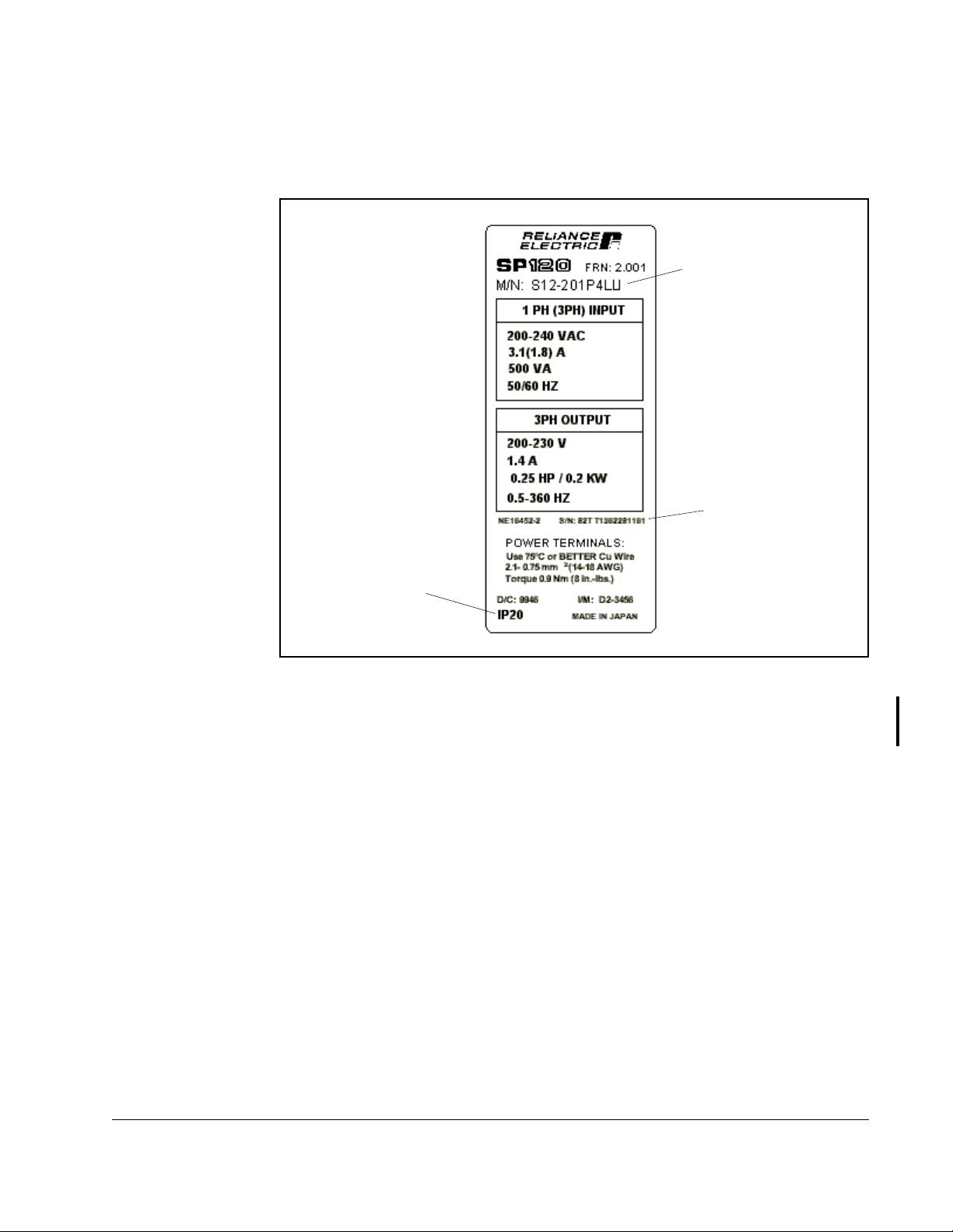
1.4 Drive Nameplate Label
Figure 1.2 depicts a typical SP120 drive nameplate label.
English
Model Number
Serial Number
Enclosure Rating
Figure 1.2 – SP120 Drive Nameplate Label
Important: The IP20 enclosure rating applies only when the SP120 AC drive is wired
for 3-phase input power. The drive is not IP20 rated when wired for
single-phase input power.
Introduction
1-3
Page 14
English
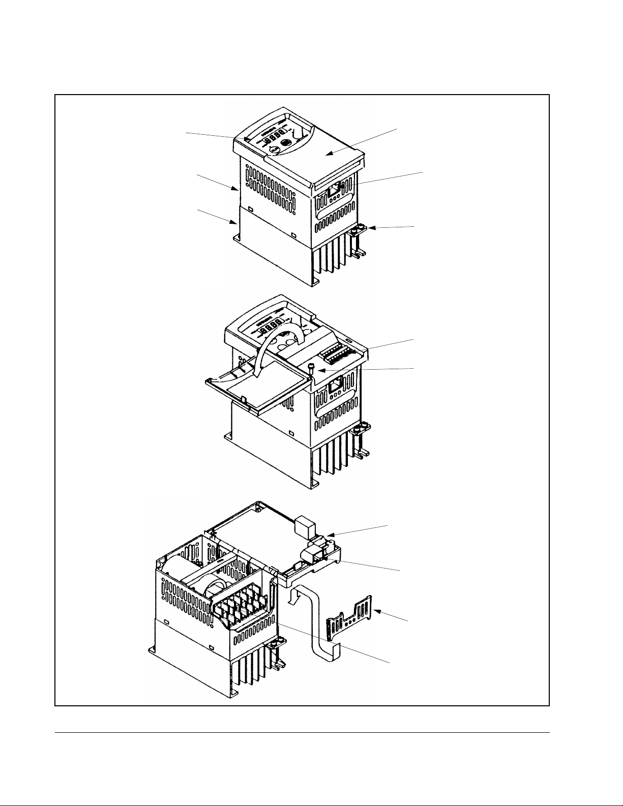
1.5 Drive Features
control panel
enclosure
heat sink
front cover
RS-422 serial interface
PE connection (M4 screw)
control terminals
screw
To wire the power terminals and
fault indication relay, loosen the
screw and open the control unit.
1-4
fault indication relay terminals
RS-422 serial interface
terminal cover
power terminals
Figure 1.3 – Drive Features
SP120 AC Drive Installation and Operation
Page 15
English
CHAPTER 2
Installing and Wiring the Drive
ATTENTION:The installation, commissioning and maintenance of these
drives may only be carried out by experienced personnel who are
!
thoroughly familiar with the functioning of the equipment and the entire
machine. Failure to observe this precaution could result in severe bodily
injury or loss of life.
ATTENTION:The devices feature DC-bus capacitors that are energized
even when the input supply is switched off. For this reason wait at least
5 minutes after switching off the input supply before you open the device
and start working on it. T ake care that you do not touch any live parts.
Failure to observe this precaution could result in severe bodily injury or
loss of lif e.
ATTENTION:Do not apply input voltage to the output terminals U/T1,
V/T2 and W/T3 as drive damage could occur.
ATTENTION:Contact the motor or machine manufacturers if standard
motors with frequencies greater than 60 Hz will be used in your
application. Failure to observe this precaution could result in damage to
equipment.
This chapter describes how to mount the SP120 drive and its external components.
Also shown are the locations and methods of wiring the power terminal block and the
control terminal block.
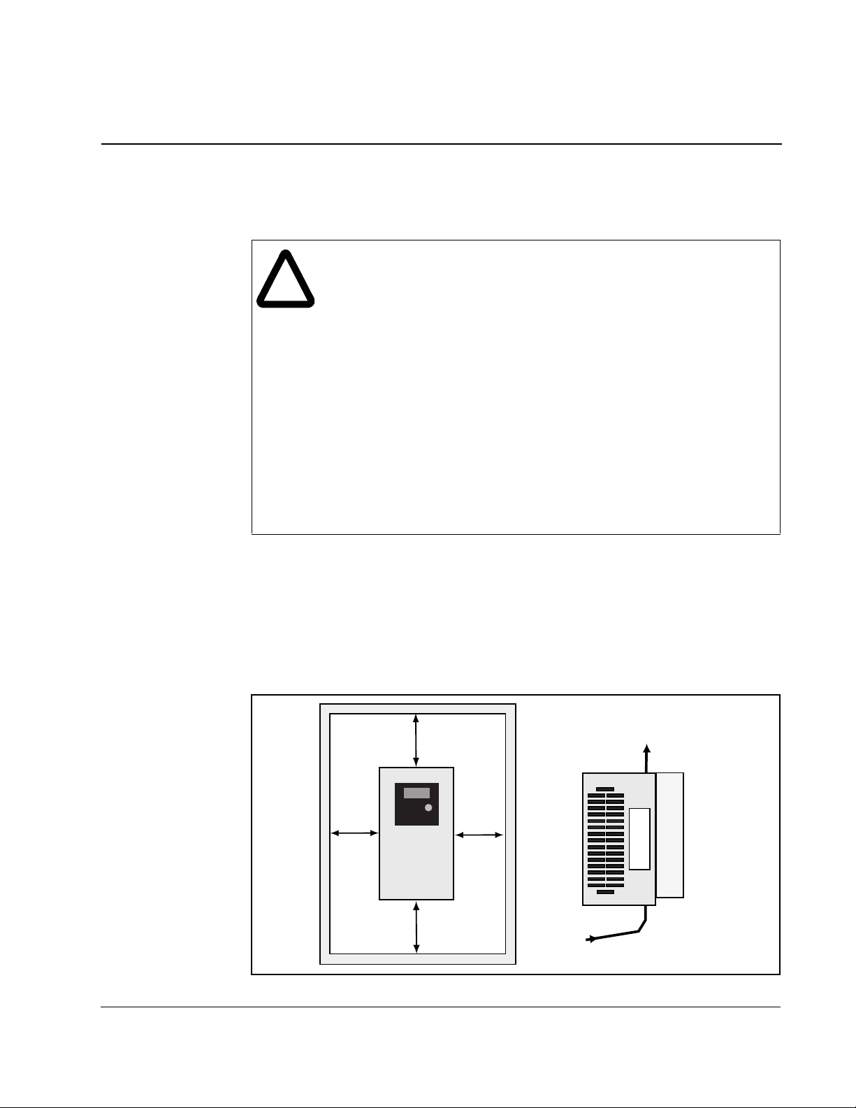
2.1 Minimum Airflow Clearances
The drive should be installed using the minimum airflow clearances shown in figure
2.1.
100 mm
(3.94 in)
30 mm
(1.18 in)
SP120
Drive
30 mm
(1.18 in)
100 mm
(3.94 in)
Air
Circulation
Installing and Wiring the Drive
Figure 2.1 – Minimum Airflow Clearances
2-1
Page 16
English
2.2 Mounting the Drive
Mount the drive on a flat, vertical, and level surface. The drive must be mounted
vertically (top up) for proper heat dissipation. Refer to Appendix A for drive mounting
dimensions.
Install the drive with four (4) M4 x .07 (8-32) screws. Torque the mounting screws to
1.2 Nm (11 lb/in).
Ensure that debris cover is in place when installing the drive to prevent filings, cable
insulation and dust from entering the drive.
2.3 Terminal Block Locations
Figure 2.2 shows the locations of the power, control, and fault relay terminal blocks.
2-2
L 5 4 3 2 1 P24
HO0I L
Control terminal block
Control Terminal Block
FM CM
21211
+1
*
L1 N/L3
L2
Power terminal block, AA01 - AA03 ratings only
S12-201P4LU / 202P6LU / 203P0LU
+1
(/)
L1 N/L3
Power terminal block, all ratings except AA01 -AA03
All other model numbers
S12-20015LU only - L1, L2, L3
*
Not Used
-
U/T1V/T2W/T3
+
––
-
L2
U/T1V/T2W/T3
* *
*
–
+
Power Terminal Block
Figure 2.2 – Terminal Block Locations
*
* Not used
Fault relay
terminal block
SP120 AC Drive Installation and Operation
AL1 AL2
AL0
F ault Relay
Terminal Block
Page 17
2.4 Wiring Power to the Drive
ATTENTION:Ensure that the input voltage corresponds to the voltage
indicated on the product nameplate. Failure to observe this precaution
!
could result in severe bodily injury or loss of life.
ATTENTION:In normal operation apply the START/STOP commands
via the control terminals or the control panel and not by disconnecting
and reapplying input power to the drive or motor contactor. If it is
necessary to use this method for starting and stopping, or if frequent
cycling of power is unavoidable, make certain it does not occur more
than once every five minutes. Do not install any capacitors or suppressors
to the drive output terminals. Failure to observe this precaution could
result in damege to equipment.
ATTENTION:Exercise particular caution if automatic restart is activated.
To prev ent injuries caused by automatic restarting of the drive following
a power failure, install a switching component at the input that is
deactivated in the event of a power f ailure and that may only be manually
switched on again on return of the power supply (e.g., contactor, etc.).
Failure to observe this precaution could result in severe bodily injury or
loss of lif e.
ATTENTION:If the distribution system capacity exceeds the drive’s
maximum symmetrical fault short-circuit current of 5,000 amps,
additional impedance must be added to the AC line supplying the drive
to limit available current in the event of a fault. Failure to observe this
precaution could resu lt in dam age to the equi pme nt.
English
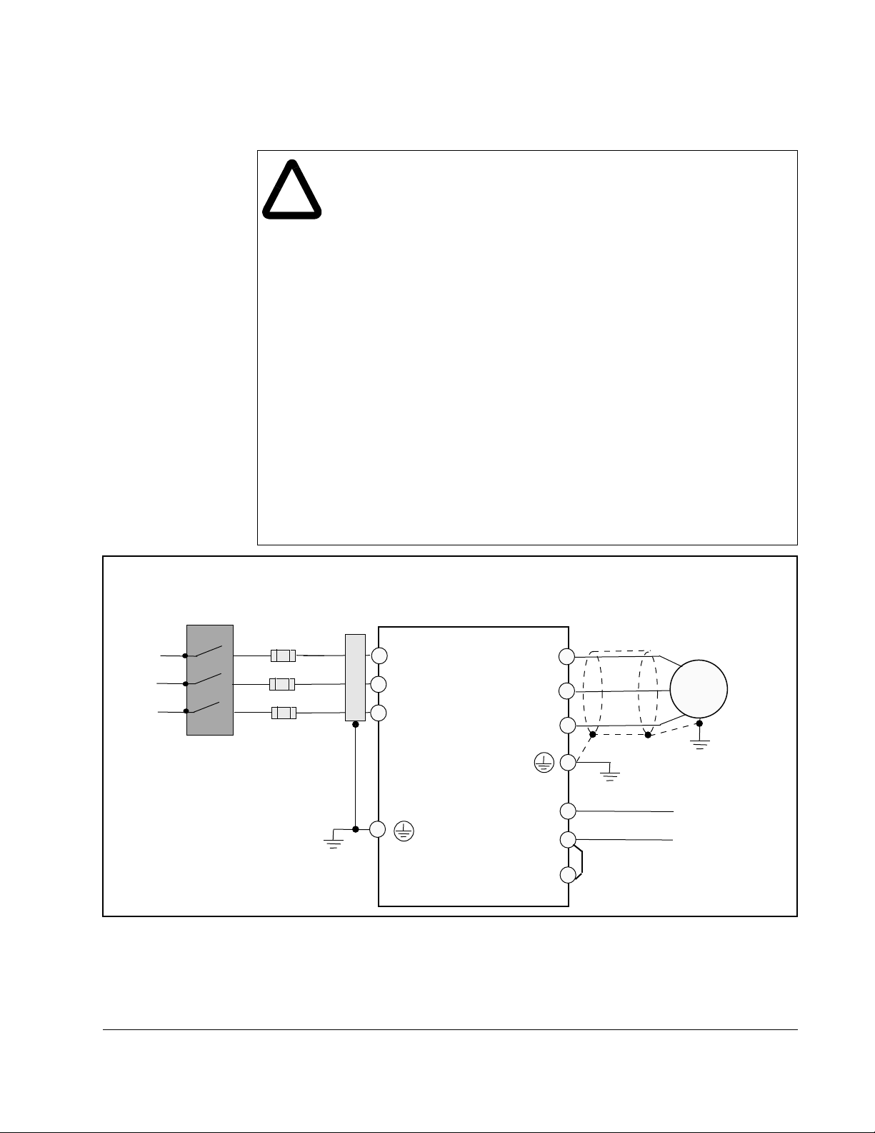
Input power supply
Disconnect
Device
Fuses
Optional
Filter
L1
L2
N/L3
U/T1
V/T2
W/T3
SP120
AC Drive
Figure 2.3 – Power Wiring Block Diagram
3
Phase
Motor
_
DC Bus
+
+1
Installing and Wiring the Drive
2-3
Page 18
English
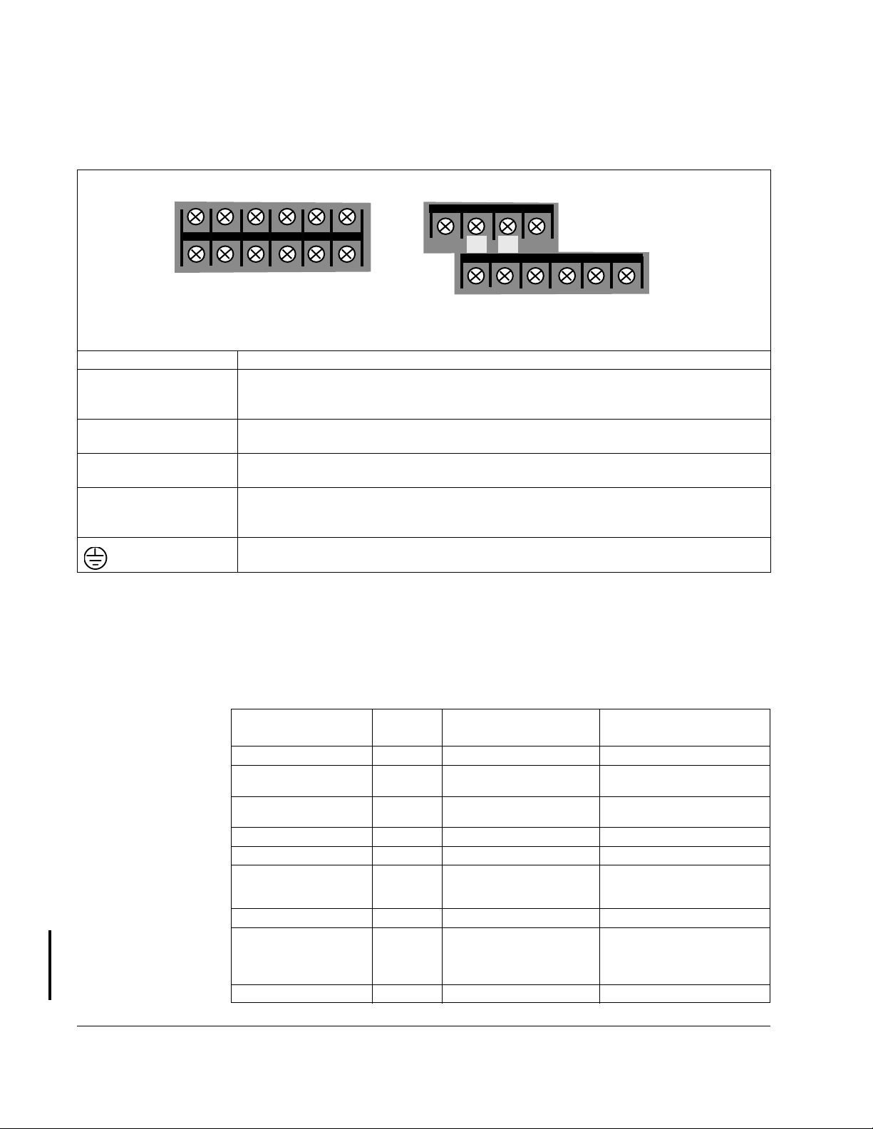
2.4.1 Power Terminal Block Descriptions
Figure 2.4 provides descriptions of the power terminal block.
+1
*
*
L1 N/L3
L2
AA01 - AA03 Power terminal block
S12-201P4LU/202P6LU/203P0LU
*
Not Used
–
+
-
*
* *
U/T1V/T2W/T3
*
All ratings except AA01 - AA03 Power terminal block
* Not used
Terminal Description
L1, L2, N/L3 Connection to incoming power.
For single phase input applications, connect the AC input power to input terminals
L1 and N/L3.
U/T1, V/T2, W/T3 Motor connections.
Use star or delta connection of the motor in accordance with the rated voltage.
+
+1
+
DC Bus connections.
Use these connections for an optional DC brake chopper.
Connection for DC bus reactor.
These terminals are connected by a copper bridge. For applications requiring a DC
bus reactor, remove the bridge prior to installing the reactor. Refer to figure 2.3.
Protective earth ground connection. Refer to figure 2.3.
Figure 2.4 – Power Termion al Block
(/)
L1 N/L3
L2
-
U/T1V/T2 W/T3
–
+
+1
All other model numbers
S12-20015LU only - L1, L2, L3
2.4.2 Power Terminal Block Wiring Specifications
The following table lists the terminal block wiring specifications for SP120 drives.
Table 2.1 – Power Terminal Block Wiring Specifications
Screw
Model
S12-101P4LU M4 5.3 – 1.3 (10 – 16) 1.3 – 1.2 (11.5 – 10.6)
S12-102P6LU
S12-104P0LU
S12-201P4LU
S12-202P6LU
S12-203P0LU M3.5 2.1 – 1.3 (14 – 16) 0.9 – 0.8 (8.0 – 7.0)
S12-204P0LU M4 5.3 – 1.3 (10 – 16) 1.3 – 1.2 (11. 5 – 10.6)
S12-205P0LU
S12-207P1LU
S12-20010LU
S12-20015LU M4 5.3 – 3.3 (10 – 12) 1.3 – 1.2 (11.5 – 10.6)
S12-401P5LU
S12-402P5LU
S12-403P8LU
S12-405P5LU
S12-408P6LU M4 5.3 – 2.1 (10 – 14) 1.3 – 1.2 (11. 5 – 10.6)
Size
M4 5.3 – 2.1 (10 – 14) 1.3 – 1.2 (11.5 – 10.6)
M3.5 2.1 – 0.75 (14 – 18) 0.9 – 0.8 (8.0 – 7.0)
M4 5.3 – 2.1 (10 – 14) 1.3 – 1.2 (11.5 – 10.6)
M4 5.3 – 1.3 (10 – 16) 1.3 – 1.2 (11.5 – 10.6)
Max/Min Wire Size mm
(AWG)
2
Max/Min Torque
Nm (in/lb)
2-4
SP120 AC Drive Installation and Operation
Page 19

2.4.3 Branch Circuit Protection Devices
The following table shows the minimum recommended values for the branch circuit
protection devices:
Table 2.2 – Branch Circuit Protection
Fuse Rating (Class J) Circuit Breaker Type
Model Single-Phase Three-Phase Single-Phase Three-Phase
S12-101P4LU 10A N/A 140M-D8N-C10
S12-102P6LU 15 A N/A 140M-D8N-C16
S12-104P0LU 20 A N/A 140M-D8N-C25
S12-201P4LU 10 A 10 A 140M-D8N-C10 140M-D8N-B40
S12-202P6LU 10 A 10 A 140M-D8N-C10 140M-D8N-B63
S12-203P0LU 10 A 10 A 140M-D8N-C10 140M-D8N-B63
S12-204P0LU 15 A 15 A 140M-D8N-C16 140M-D8N-C10
S12-205P0LU 15 A 15 A 140M-D8N-C16 140M-D8N-C10
S12-207P1LU 20 A 15 A 140M-D8N-C16 140M-D8N-C16
S12-20010LU 30 A 20 A 140M-D8N-C25 140M-D8N-C16
S12-20015LU N/A 30 A N/A 140M-D8N-C25
S12-401P5LU N/A 3 A N/A 140M-D8N-B25
S12-402P5LU N/A 6 A N/A 140M-D8N-B40
S12-403P8LU N/A 10 A N/A 140M-D8N-B63
S12-405P5LU N/A 10 A N/A 140M-D8N-C10
S12-408P6LU N/A 15 A N/A 140M-D8N-C16
English
N/A
N/A
N/A
2.4.4 Input Power Conditioning
The drive is suitable for connection to input power within the rated voltage of the drive
(see specifications). The power factor of the input power supply must not exceed .99.
Compensation systems must ensure that overcompensation does not occur at any
time.
If the drive must be installed in any of the following conditions, a 3% impedance input
line reactor must be used:
• line has intermittent noise spikes in excess of 2000 V
• frequent voltage dips occur
• the drive is operated on a generator
• line has power factor correction capacitors
• several drives are linked via a short common power supply bus bar
Installing and Wiring the Drive
2-5
Page 20
English
Drive HP
S12-x01P4xx 0.25 RL-00201 12 2RB003 20
S12-x01P5xx 0.50 RL-00202 20 2RB003 20
S12-x02P5xx 1.0 RL-00201 12 4RB002 12
S12-x02P6xx 0.50 RL-00204 6 4RB002 12
S12-x03P0xx 0.75 RL-00401 3 4RB002 12
S12-x03P8xx 2.0 RL-00402 6.5 4RB003 15
S12-x04P0xx 1.0 RL-00401 3 9RB003 7.5
S12-x05P0xx 1.5 RL-00801 1.5 9RB003 7.5
S12-x05P5xx 3.0 RL-00402 6.5 9RB004 11.5
S12-x07P1xx 2.0 RL-00801 1.5 12RB003 4
S12-x08P6xx 5.0 RL-00802 3.0 12RB004 15
S12-x0010xx 3.0 RL-01201 1.25 18RB003 2.75
S12-x0015xx 5.0 RL-01801 0.8 25RB04 1.75
2.4.5 Motor Protection
Table 2.3 – AC Line Reactors and DC Chokes
AC Line Reactors DC Chokes
MTE Part No. mH MTE Part No. mH
SP120 drives feature electronic overload protection to monitor the motor current. In
the case of multi-motor operation, thermal contacts or positive temperature coefficient
(PTC) resistors must be used for each motor. In the case of motor lead lengths greater
than 50 meters (165 feet), motor reactors should be used.
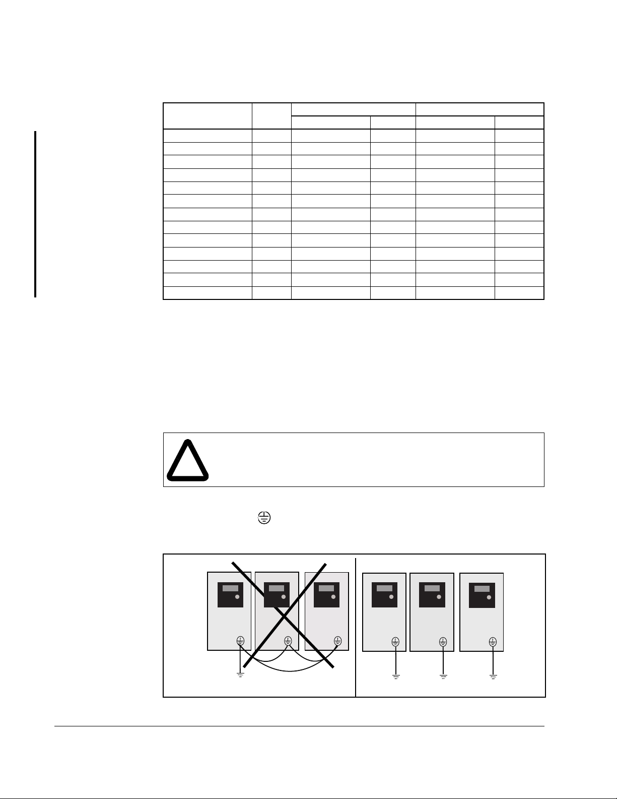
2.4.6 Grounding the Drive
ATTENTION:The SP120 drive has a high leakage current and must be
permanently hard wired to ground. Failure to observe this precaution
!
Ground the drive by connecting a ground wire from the drive’s input grounding
terminal (labeled PE ) uninterrupted to earth ground. Be sure to separate the
drive’s grounding pole from those of other electrical machinery. If multiple drives are
used, make certain each drive is grounded separately (see figure 2.5).
could result in severe bodily injury or loss of life.
SP120 DriveSP120 DriveSP120 DriveSP120 Drive
SP120 Drive
SP120 Drive
2-6
Protective
Earth
Ground
Protective
Earth
Ground
Figure 2.5 – Grounding the Drive
SP120 AC Drive Installation and Operation
Page 21
2.5 Wiring the Control Terminal Block
ATTENTION:Control terminals are isolated, but not tied to earth ground.
If terminal (L) on the control terminal block is not grounded, exposed
!
Ensure that the following requirements are met when wiring the control terminal block:
• Run all signal wiring in either a shielded cable or separate metal conduit.
• Do not exceed control wiring length of 20 meters (65.6 feet).
• Use 0.75 mm
0.5-0.6 Nm (4.4-5.3 in lb).
• Use 18 AWG to 28 AWG (0.75 to 0.14 mm
wire for all other signal connections. Torque all connections to 0.2 to 0.25 Nm (1.77
to 2.21 in lb).
conductors, shields or metal conductors can be at hazardous voltage
levels. Failure to observe this precaution could result in severe bodiy
injury or loss of life.
2
(18 AWG) wire for the alarm relay. Torque the mounting screws to
2
), twisted pair, shielded, or 3-conductor
English
• Avoid crossing the power lines or motor lines with the control wires. If they must
cross, ensure that they cross at right angles (90
• If using transistor outputs 11 or 12 with an inductive load such as a relay, install a
recovery diode parallel to the relay, as shown in figure 2.6, to prevent damage to the
output.
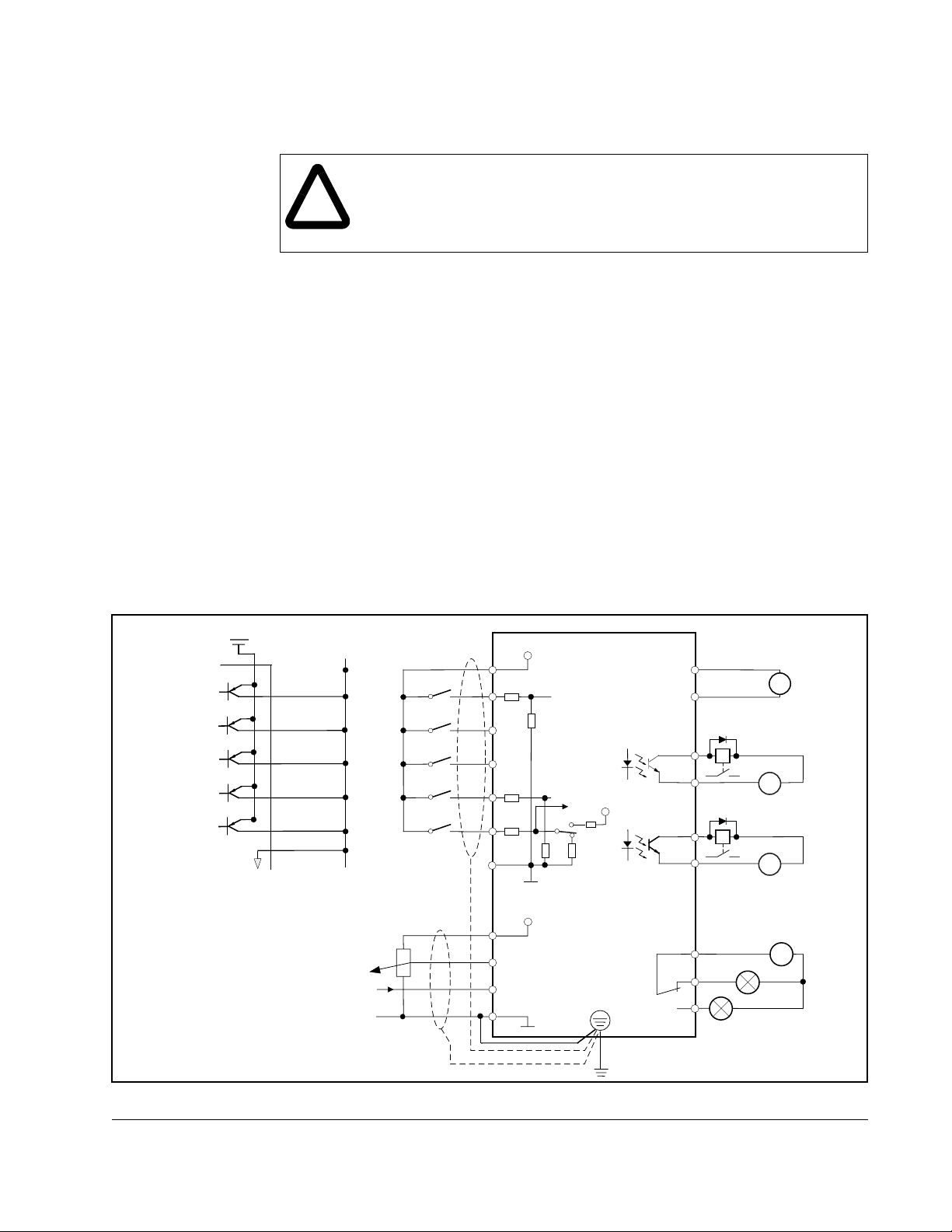
Figure 2.6 shows typical control terminal connections.
24V
IMPORTANT: Only one frequency
source may be connected at a time.
If more than one reference is
connected at the same time,
an undetermined frequency
reference will result.
To improve noise immunity, the
control terminal block common
(terminal L) must be connected
to ground terminal/protective earth.
External
Power
1-2k Ohm Pot.
Internal
Power
P24
1
2
3
4
5
L
Frequency Reference
0-10V
4-20mA
P24
1
4.4k
2
3
4
4.4k
5
4.4k
L
H
O
OI
L
24V
680
10V
680
PTC
680
5.1k
5V
o
).
FM
L
11
CM2
12
CM2
AL0
AL1
AL2
V
=
–
24V
=
–
24V
Fault Relay
230V AC
~
0-10V
+
+
Installing and Wiring the Drive
Figure 2.6 – Typical Control Terminal Connections
2-7
Page 22
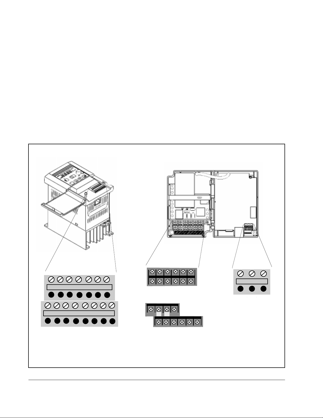
English
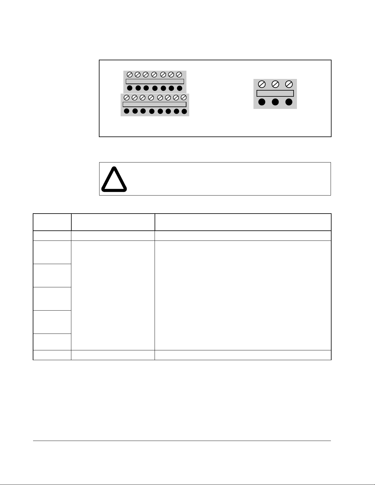
Figure 2.7 and table 2.4 provide descriptions of the drive control terminals and fault
relay terminals.
L 5 4 3 2 1 P24
AL1 AL2
AL0
Fault relay
HO0I L
Control T erminal Block
Control Terminal Block
ATTENTION:Do not jumper or short circuit terminals H and L or P24
and L. Failure to observe this precaution could result in damage to, or
!
Table 2.4 – Control Terminal and Fault Relay Terminal Descriptions
destruction of, the equipment.
FM CM
21211
Figure 2.7 – Control Terminal Block and Fault Relay Terminal Block
Fault Relay
terminal block
Terminal Block
Control
Terminal Function Description
P24 24 V DC 24 V potential or digital inputs 1-5, max. load 30 mA
1 Programmable Digital Inputs.
26 V max, 5 KΩ input
impedance.
2
Digital inputs 1 – 5 are fully programmable level triggered
inputs. An overview of the possible functions can be found in
the digital input description table in section 2.6
The inputs are fully programmable with these exceptions:
• No two inputs can have the same function
3
4
5
L 0 V 0 V potential for output FM
• Only input 5 can be programmed as PTC.
With the exception of the reset setting, which must be NO
(active high), all of the inputs can be set as NO (active high) or
NC (active open) via parameters C11 [
DIGITAL INPUT 5 LOGIC].
C15 [
Note: A signal must be applied to the digital inputs for at least
12 msec in order to be read by the drive.
DIGITAL INPUT 1 LOGIC] to
2-8
SP120 AC Drive Installation and Operation
Page 23
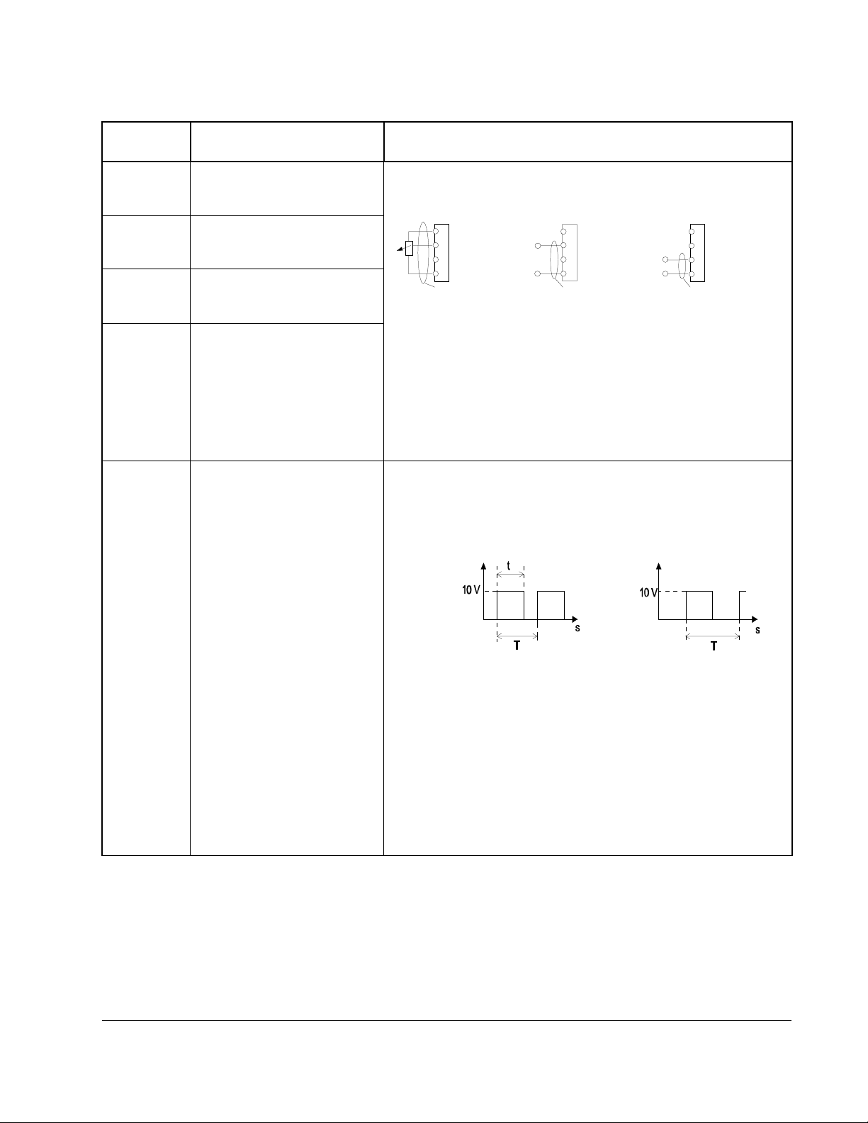
Table 2.4 – Control Terminal and Fault Relay Terminal Descriptions
Control
Terminal Function Description
H 10 V Reference Voltage for
Analog Frequency
Command
O Voltage Analog Input
Frequency Command
(0-10 V)
OI Current Analog Input
Frequency Command
(4-20 mA)
L 0 V Reference Potential for
Frequency Comand Inputs
Potentiometer
1 to 2 kOhm
H
O
OI
L
PE PE
nominal 0-10 V nominal 0-20 mA
H
+
O
Input impedance
OI
10 kOhm
L
Input OI for 4-20 mA is activated when one of the digital inputs
is set to 16{AT} via parameters C01 [
DIGITAL INPUT 5].
[
The analog input reference can be adjusted using parameters
ANALOG FREQUENCY MINIMUM] to A16 [ANALOG FILTER
A11 [
SELECT].
If no digital input is programmed as 16{AT}, the set values are
the sum of O and OI.
FM Programmable Analog
Output
This output can be used to monitor the output frequency of the
drive (either Analog or Pulse) or the motor current. This output
is programmable using parameter C23 [
Analog or Pulse Output
Frequency or Motor Current
Analog Signal
Frequency or Current
English
4-19.6 mA0-9.6 V
H
O
+
-
DIGITAL INPUT 1] to C05
OUTPUT FM].
Pulse Signal (50% duty cycle)
Frequency only
Input impedance
OI
250 Ohm
L
PE
Installing and Wiring the Drive
T = 4 ms (constant) T = (Variable)
Analog Signal: The relation t/T (duty cycle) changes
proportionally with the frequency or current. The maximum
voltage of 10V (100% duty cycle) is reached when the
maximum frequency or 200% of the rated current is reached.
Parameter b81 [
OUTPUT FM FACTOR] may be used as a scaling
factor.
Accuracy: +/- 5% for frequency , +/- 20% for current
Pulse Signal: Frequency = output frequency x b86 [
DISPLAY SCALE FACTOR], but the maximum frequency is 3.6 kHz
PROCESS
(ex. Freq = 60Hz x 60 = 3.6kHz).
2-9
Page 24
English
Table 2.4 – Control Terminal and Fault Relay Terminal Descriptions
Control
Terminal Function Description
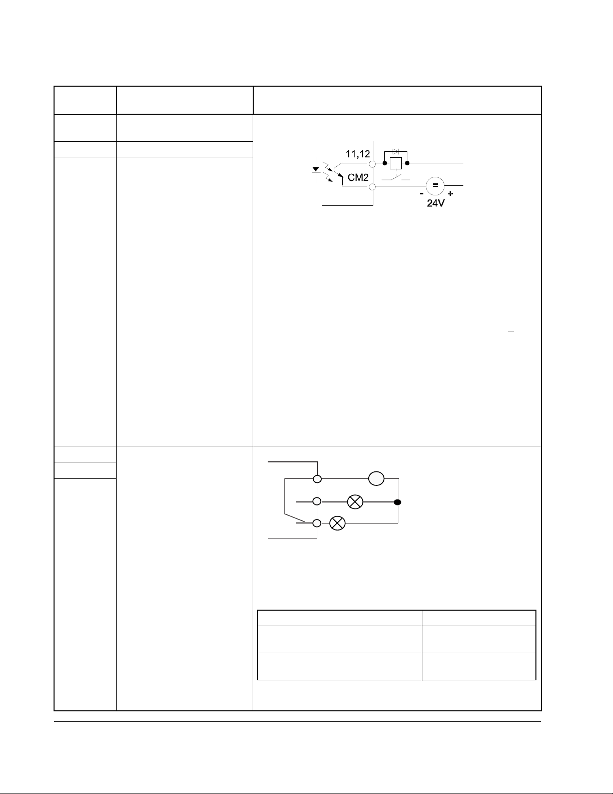
CM2 Reference potential for
outputs 11 and 12
12 Programmable Digital Output
11 Programmable Digital Output
AL0 Fault Relay
AL1
AL2
Transistor output, max. 27 Vdc, 50 mA
The outputs can be programmed as either NO (active high) or
NC (active open) contacts using parameter C31 [
OUTPUT 11LOGIC] and C32 [DIGITAL OUTPUT 12 LOGIC].
The following 6 settings may be programmed using parameter
DIGITAL OUTPUT 11] and C22 [DIGITAL OUTPUT 12]:
C21 [
00{RUN} = Motor Running (Signal if output frequency > 0.5 Hz)
01{FA1} = At frequency (Signal when the set frequency is
reached and that frequency is > 0.5Hz)
02{FA2} = Above frequency (Signal if output frequencies >
frequencies set under parameter C42 [
FREQUENCY ACCEL SETTING] or C43 [ABOVE
FREQUENCY DECEL SETTING] and > 0.5 Hz).
03{OL} = Motor overload (Signal if the motor current exceeds
the value set under C41 [
04{OD} = PID-deviation (Signal if the deviation between the set
value and the actual value returned is greater than the
value set under C44 [
PID DEVIATION SETTING]). Only
available if the PID control A71 [
05{AL} = Fault (Signal if a fault is indicated)
AL0
AL1
230VAC
∼
DIGITAL
the
ABOVE
OVERLOAD ALARM SETTING]
PID ENABLE] is active.
250 VAC, 2.5 A resistive
0.2A inductive
30 VDC, 3.0A resistive
0.7A inductive
2-10
AL2
Faulted / De-energized State
Parameter C33 [
FAULT RELAY AL1 LOGIC] can be used to invert
min. 100 VAC, 10mA
5 VDC 100 mA
the operation.
C33 C33 = 01 C33 = 00
AL0 - AL1 Open when Faulted
Open when Power Off
AL0 - AL2 Closed when Faulted
Closed when Power Off
Closed when Faulted
Open when Power Off
Open when Faulted
Closed when Power Off
The fault relay is set with a time delay of approximately 2 sec
after the power is switched on.
SP120 AC Drive Installation and Operation
Page 25

2.6 Programmable Digital Input Functions
(Control terminal block inputs 1 through 5)
The function of the digital inputs 1 through 5 are programmed via the corresponding
parameters: C01 [
programming guidelines must be followed:
• No two inputs can be programmed for the same function.
• The PTC input (setting 19) is only programmable on input terminal 5.
The digital inputs can be programmed to respond to NO (Active High) or NC (Active
Open) inputs via parameters C11 [
LOGIC].
!
DIGITAL INPUT 1] through C05 [DIGITAL INPUT 5]. The following
DIGITAL INPUT 1 LOGIC] through C15 [DIGITAL INPUT 5
ATTENTION:All digital inputs respond to level sensitive commands.
Inputs do not require a voltage transition (cycle) after a fault condition is
cleared, after input power cycling, or after programming the logic of the
digital input.
All digital inputs can be programmed as NO or NC. However, the start
command should be set as NO (active high) and the stop command
should be set as NC (active open). If set opposite of this, an inadvertent
start or failure to stop could occur should a discrete connection be lost
or control wire come loose. If the user chooses to disregard this safety
practice - the risk assumed by the user can be reduced by assuring that
other safeguards are used to insure proper start and stop operation.
Depending on the application: This may include appropriate emergency
stops, redundant wiring, electronic guards and/or mechanical guards.
Failure to observe this precaution could result in severe bodily injury or
loss of lif e.
English
Installing and Wiring the Drive
Table 2.5 describes the programmable digital input functions.
2-11
Page 26
English
Table 2.5 – Programmable Digital Input Functions
Numeric
Setting
Alpha
Setting Function Description
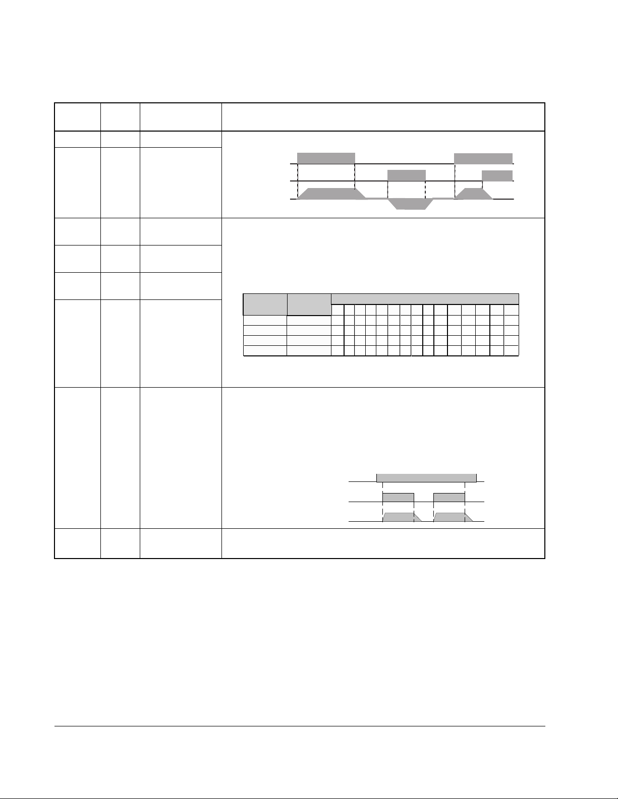
00 {FW} Forward 2-Wire (maintained) Run Forward/Run Reverse settings.
01 {RV} Reverse
02 {CF1} Preset
frequency input
03 {CF2} Preset
frequency input
04 {CF3} Preset
frequency input
05 {CF4} Preset
frequency input
00{FW}(N.O.)
01{RV}(N.O.)
Motor Speed
The preset frequencies may be programmed in two ways:
1. By programming desired preset frequency values via parameters
PRESET FREQUENCY 1] through A35 [PRESET FREQUENCY 15].
A21 [
2. By selecting the corresponding digital input setting and entering the
desired frequency via parameter F01 [
Setting
02
03
04
05
Input
CF1
CF2
CF3
CF4
1 2 3 4 5 6 7 8 9 10 11 12 13 14 15
ON
ON
ON
ON
ON
ON ON
FREQUENCY COMMAND].
Preset Speed
ON
ON
ON
ON
ON
ON ON
ON ONONONONON
ON ON
ON ON
ON ON ON ON
ON ON ON ON
Note: If any preset frequency input is active, all other frequency
commands will be ignored.
06 {JG} Jog When this input is active, the 00{FW} or 01{RV} inputs will respond to
the frequency programmed via parameter A38 [
JOG FREQUENCY]. The
accel ramp is NOT active.
09 {2CH}
nd
Accel/Decel
2
ramp
The stop command is determined by parameter A39 [
JOG STOP MODE].
Note: The Jog command will not work with 3-wire control.
Input 06 {JG} (NO)
Run CMD (NO)
Motor Speed
2nd Accel/Decel ramp times are activated via this input and programmed
via parameter A92 [
ACCEL TIME 2] and A93 [DECEL TIME 2].
2-12
SP120 AC Drive Installation and Operation
Page 27
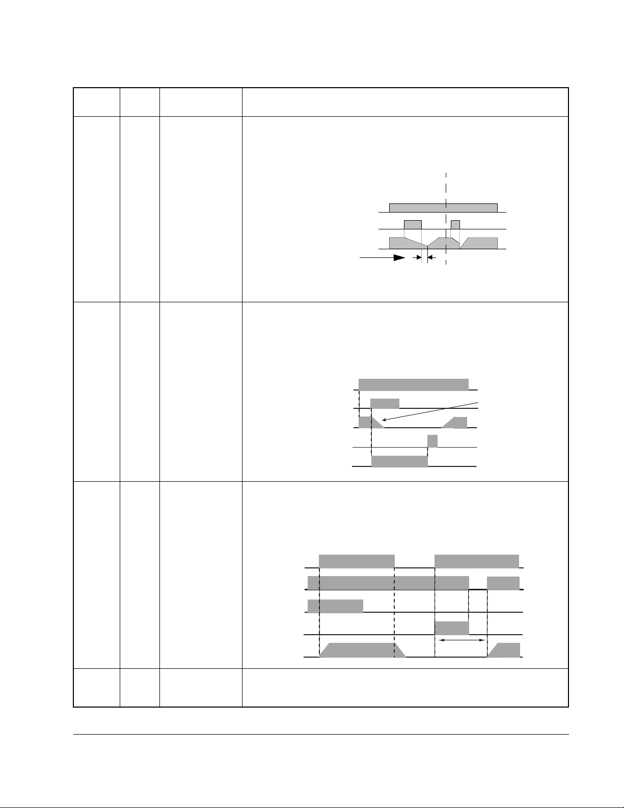
Table 2.5 – Programmable Digital Input Functions
English
Numeric
Setting
Alpha
Setting Function Description
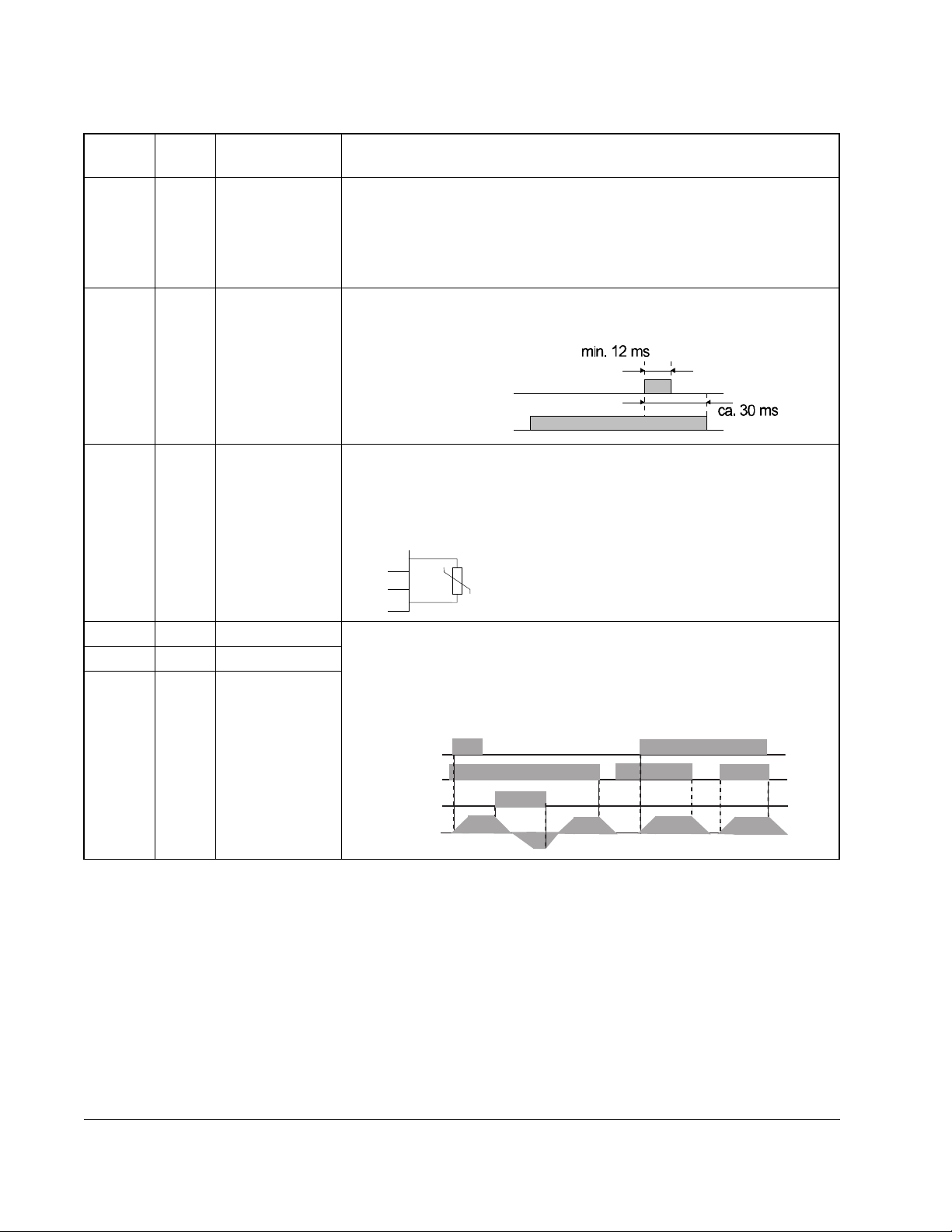
11 {FRS} Coast to Stop The motor voltage will be switched off immediately and the motor will
coast. This function can be programmed to operate in two different
modes via parameter b88 [FRS Select].
synchronization of
motor speed
0 Hz start
Run (NO)
Input 11 {FRS} (NO)
Motor Speed
Waiting time
Note: The drive will start when 11 {FRS} input is removed without
reissuing a start command even if in 3-wire (momentary) control.
12 {EXT} External Fault When this input is active, an E12 fault indication will be issued (e.g. an
input received from thermal contacts). The fault indication will be
cleared with a reset 18 {RS}.
Important: After a reset 18{RS} command, the drive will start again if a
start command is active (00{FW}, 01{RV},or 20 {STA}).
Run (NO)
Input 12 {EXT} (NO)
Motor will
Coast
Motor Speed
Input 18 {RS} (NO)
Fault relay (AL0-Al2) (NO)
13 {USP} Unintentional
Start Protection
on Power Up
This function is designed to guard against unintended starting when
input power is removed and then restored. In this case, if a start/run
command is issued immediately upon/after power is restored an E13
fault will be issued. A new start command or a reset 18 {RS} command
will clear the fault indication.
Power Supply
00{FW} or
01 {RV} (N.O.)
13 {USP}(N.C.)
Fault relay (N.O.)
Motor Speed
Min. 3 Sec
15 {SFT} Program Lock Protects stored parameter values from being overwritten. See
parameter b31 [
PROGRAM LOCK SELECT] for the 4 different levels of
protection.
Installing and Wiring the Drive
2-13
Page 28
English
Table 2.5 – Programmable Digital Input Functions
Numeric
Setting
Alpha
Setting Function Description
16 {AT} 4-20mA Select Activates input terminal OI for use as a 4-20 mA input. If no input
terminal is programmed for this setting, the factory default input is O
(0-10V) and the output frequency will correspond to the value of the
inputs to the O and/or OI control inputs.
Note: Parameter A01 [
FREQUENCY COMMAND SELECT] determines from
what source the output frequency is commanded.
18 {RS} Reset Used to clear a fault condition. If a 18 {RS} command is given during
operation, the output IGBTs are switched off and the motor will coast.
18 {RS} (NO)
Fault indication
19 {PTC} PTC Input This input can only be programmed to digital input terminal 5 and
the PTC should be referenced to terminal L.
If the PTC resistance exceeds 3k Ohms, the output voltage to the motor
will be switched off and an E35 fault code will be issued.
5
L
20 {STA} 3-wire run 3-wire (Momentary) control inputs. Both settings 20 {ST A} and 21 {STP}
21 {STP} 3-wire stop
22 {F/R} 3-wire
must be programmed as digital inputs for 3-wire control to function. If 20
{STA} is programmed into any digital input then 2-wire (maintained)
control will not function.
Forward/Reverse
Note: 3-wire stop command (21 {STP}) cannot be used to clear a fault.
20{STA} (NO)
21{STP} (NC)
22 {F/R (NO)
Motor Speed
2-14
SP120 AC Drive Installation and Operation
Page 29
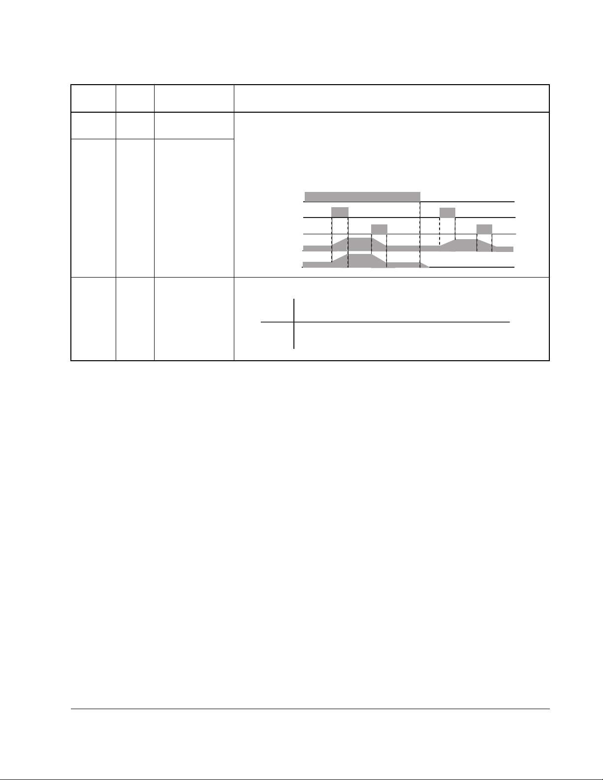
Table 2.5 – Programmable Digital Input Functions
English
Numeric
Setting
Alpha
Setting Function Description
27 {UP} Remote Control UPThese settings allow digital inputs to increase and decrease the
FREQUENCY
28 {DWN} Remote Control
DOWN
commanded frequency for the drive. Parameter A01 [
COMMAND SELECT] must be set to 02 to activate this function. These
inputs will change the value of parameter F01 [
Hz/sec as defined by parameter A04 [
MAXIMUM FREQUENCY] ÷ (Accel
FREQUENCY COMMAND] in
time or Decel time).
RUN (NO)
27 {UP} (NO)
28 {DWN} (NO)
PF01-
[Freq. Command]
Motor Speed
31 { OPE} Run Comm and
This setting is used to determine the source of the Run commands.
Source Select
Inactive
Active
Start command will come from the control terminals only,
regardless of the setting of PA02 - [Start Command Select]
Start command will come from the start key on the keypad only
regardless of the setting of PA02 - [Start Command Select]
Installing and Wiring the Drive
2-15
Page 30

English
2-16
SP120 AC Drive Installation and Operation
Page 31

CHAPTER 3
Parameters and Programming
This chapter describes how to program the drive and provides a parameter reference
that describes all of the drive parameters.
3.1 Programming the Drive Using the Keypad
ATTENTION:Wait at least 6 seconds after programming the SP120 drive
before issuing a start, reset command, or switching off the power supply.
!
The keypad is located on the front panel of the drive. This is an integrated keypad that
can be used to monitor drive operation, program parameters, and operate the drive.
The PROGram, Up Arrow, Down Arrow, and Enter keys are located inside the front
panel cover. You must open the cover to access these keys. The drive uses a
4-character, 7-segment LED display to show parameter numbers, parameter values,
and diagnostic codes. Refer to section 4.4 for a description of the diagnostic codes.
Failure to wait 6 seconds could result in failure to recognize programming
changes, which could result in bodily injury or damage to equipment.
ATTENTION: If the Stop key is used to clear a fault and there is a valid
run command, the drive will start to run as soon as the fault is cleared
without cycling the run input. Failure to observe this precaution could
result in severe bodi ly injury or loss o f life.
Table 3.1 – Keypad Functions
English
Key Description
PROGram is a dual purpose key. It is used to view parameter
groups and to switch between parameter numbers and values.
PROG
Min
Max
PROGram also acts as an escape key to exit the parameter
values without changing them.
Up Arrow and Down Arro w are used to scroll through
parameters, or to increase and decrease parameter values.
Enter is used to enter the current value into memory.
Start can be activated using A02 [
digital input setting 31{OPE}. When active, the key will start
the motor in the direction of rotation defined in F04 [
DIRECTION].
The Speed Potenti o m e ter can be used to set the
commanded speed. The speed potentiometer can be
activated using A01 [
Stop is used to stop the motor. If the drive has stopped due to
a fault, pressing this key will clear the fault.
FREQUENCY COMMAND SELECT].
START COMMAND SELECT] or
START KEY
Parameters and Programming
3-1
Page 32

English
Table 3.2 – LED Functions
LED Will be on when:
POWER power is applied to the drive (mains supply is switched on).
Important: The DC-bus capacitors and terminals are
energized even when the mains supply is
switched off.
RUN the drive is in operation. For example, if a start command
has been given.
PRG
Hz
A
the drive is being programmed.
output speed is being displayed.
output current is being displayed.
Start Key the Start key has been pressed.
Speed Pot the speed pot is active.
d01
d09
F01
F04
d01d01d01d01
A ..
b ..
C ..
A01
A98
PROG
b01
PROG
PROG
Figure 3.1 – Programming Overview
b89
C01
C91
Parameter
PROG
Saving entered
Parameters
Entry
3-2
SP120 AC Drive Installation and Operation
Page 33

3.1.1 Programming Examples
This section contains four different programming examples to help describe how to
program the SP120 drive.
Initial Power Up
This example shows you how to proceed from the power up parameter value to the
parameter number.
Action Description Display
Apply power to the drive
If you were viewing a display parameter when power was last
removed from the drive, the same display parameter value will
reappear when the drive is re-powered. If you were viewing any
other parameter value when power was removed, the
parameter group or parameter number will appear when the
drive is re-powered.
Press PROGram to switch from the parameter value to the
parameter number.
PROG
English
0.0
d01
Parameters and Programming
3-3
Page 34

English
Scrolling through parameter groups
This example shows you how to check a parameter value without changing the value
of the parameter. For this example, the operation of C21 [
verified.
Action Description Display
Press Up Arrow or Down Arrow to scroll through the
parameter groups, stopping at the C group.
Note: All of the d and F group parameters are
displayed in sequence, but the A, b, and C
parameters are grouped and the group must be
selected to view the parameters within that specified
group. Figure 3.1 details which parameters are in
each group.
Press PROGram to enter into the C group. C01
DIGITAL INPUT 1] should appear on the display.
[
DIGITAL OUTPUT 11] is
C--
C01
PROG
Note: When parameter groups are entered, the
number of the parameter that was being viewed
when you last exited the group will be displayed.
Press Up Arrow to scroll through the parameters
contained within the group, continue pressing Up
Arrow until C21 [
DIGITAL OUTPUT 11] is displayed.
C21
PROG
PROG
PROG
Note: When viewing parameters within the A, b and
C groups the parameters will wrap from A01 through
C91 by pressing Up Arrow or Down Arrow. To view
parameters within the d and F groups, press SELect
until the display shows A - -, b - - or C- -. Once the
group letter is displayed, Up Arrow or Down Arrow
will scroll to the d and F parameters.
Press PROGram to view the parameter value stored
in C21 [
Press PROGram again to exit from the parameter
value back to the parameter number without
changing the stored value.
Press PROGram again to exit from the parameter
number to the parameter group display.
DIGITAL OUTPUT 11].
01
C21
C--
3-4
SP120 AC Drive Installation and Operation
Page 35

Restoring Factory Defaults
This example shows you how to reset the factory defaults of the drive.
Action Description Display
Press Down Arrow to advance to the b parameter
group.
English
b--
PROG
PROG
PROG
PROG
Press PROGram to enter into the b parameter
group.
Press Up Arrow to scroll through the parameters
until b84 [
Press PROGram to view the parameter value stored
in b84 - [
01. If it is not 01, use Up Arrow to change the value
to 01, then press Enter.
Note: The defaults will be reset to the values
determined by b85 [
Press PROGram to return to the parameter number
without changing the stored value.
Press and hold PROGram, Up Arrow, Down Arrow,
and Stop for 3 seconds.
RESET FUNCTIONS] is displayed.
RESET FUNCTIONS] and verify that it is set to
FACTORY DEFAULT SELECt].
b01
b84
01
b84
b84
Parameters and Programming
PROG
Release the Stop Key and continue to hold the
PROGram, Up Arrow, and Down Arrow until the
display begins to blink. Release the remaining keys.
When this is done, 0.0 will be displayed (this is d01
OUTPUT FREQUENCY].
[
0.0
3-5
Page 36

English
Setting Drive Control to the Keypad
This example shows you how to configure the drive for ke ypad control. You will need to
change the values of three parameters to accomplish this.
Step 1. Pr ogram A0 1 [
Step 2. Pr ogram A0 2 [
Step 3. Pr ogram C13 [
Step 4. Verify that F04 [
Action Description Display
PROG
PROG
PROG
Press PROGram to switch from the parameter value to the parameter number.
Press Up Arrow or Down Arrow to scroll through the parameter groups stopping at
the A group.
Press PROGram to enter into the A group.
If a parameter other than A01 [FREQUENCY COMMAND SELECT] is displayed press
Down Arrow until A01 is displayed.
Press PROGram to view the parameter value.
Use Down Arrow to change the value of A01 from the default value of 01 to 00.
This changes the source of the frequency command to the potentiometer on the
fixed keypad.
When the desired value is displayed, press the Enter Key. This writes the new
value to memory. The display will return to the parameter number.
Press Up Arrow to display A02 [START COMMAND SELECT].
Step 5. Verify that C1 through C5 [
reference command from the control terminal block (factory default) to the
speed potentiometer on the keypad.
input from the control terminal block (factory default) to Start on the keypad.
closed contact (NC) to a normally open contact (NO).
FREQUENCY COMMAND SELECT] to change the frequency
START COMMAND SELECT] to change the source of the start
DIGITAL INPUT 3 LOGIC] to change the input from a normally
START KEY DIRECTION] is not set to 2 (Control Terminal).
DIGITAL INPUTS 1-5] are at default values.
d01
A--
A01
00
01
00
A01
A02
3-6
PROG
PROG
Press PROGram to view the parameter value stored in A02.
Use Up Arrow to change the value of A02 from the default value of 01 to 02. This
changes the source of the start input from the control terminal block to the fixed
keypad.
When the desired value is displayed, press Enter. This writes the new value to
memory. The display will return to the parameter number.
Press Down Arrow until C13 [DIGITAL INPUT 3 LOGIC] is displayed.
Press PROGram to view the parameter value.
Use Down Arrow to change the value of C13 from the default value of 01 to 00.
This changes the input to a normally open contact.
When the desired value is displayed, press the Enter Key. This writes the new
value to memory. The display will return to the parameter number.
SP120 AC Drive Installation and Operation
01
02
A02
C13
01
00
C13
Page 37

3.2 Parameter Descriptions
High
Open
High
Open
The sections that follow provide descriptions of all drive parameters, separated by
group.
3.2.1 D Group - Display and Diagnostic Parameters (Read Only)
This group of parameters consists of commonly viewed drive operation conditions
such as output frequency. All parameters in this group are Read Only.
English
Parameter
Number Parameter Name / Description
d01 Output Frequency
Displays the output frequency to the motor.
d02 Output Current
Displays the output current to the motor.
d03 Direction
Displays the present direction of rotation.
d04 PID Process Display
Displays the scaled PID Process variable (feedback). Available only
when the PID control is active. The scale factor is set using A75
PROCESS REFERENCE SCALE FACTOR].
[
d05 Digital Input Status
Displays the status of the 5 digital inputs regardless of how each input
is programmed in C11 [
RELAY AL1 LOGIC].
5 4 3 2 1
DIGITAL INPUT 1 LOGIC] through C33 [ALARM
d06 Output Status
Displays the status of the digital outputs and the fault indication
relays.
AL 12 11
Min./Max.
Range Units
0.0 to 360.0 N/A
0.00 to 999.9 0.01 A
F=Forward
N/A
r=Reverse
o=Stop
0.00 to 100.0 0.01%
N/A N/A
N/A N/A
d07 Process Display
Displays d01 [
PROCESS DISPLAY SCALE FACTOR].
[
Note: If there are more than 4 digits, the LSB will be dropped.
d08 Last Fault
Displays the last fault. The output frequency, motor current, and DC
bus voltage at the time of the last fault can be viewed by pressing
PROGram. If there has not been a fault or the register has been
cleared, then --- will be displayed.
Parameters and Programming
0.00 to 9990 0.01
OUTPUT FREQUENCY] scaled by the variable set in b86
N/A N/A
3-7
Page 38

English
Parameter
Number Parameter Name / Description
d09 Fault Register
Displays the second and third fault. If there are no faults stored in this
register, then --- will be displayed. To view the third fault, press
PROGram.
d16 Elapsed Run Time
Displays the elapsed running time of the drive. The elapsed running
time is the displayed value x 10.
3.2.2 F Group – Basic Function Parameters
Tunable parameters are indicated with an asterisk ( * ) precediing the parameter
number.
Number Parameter Name / Description
*F01 Frequency Command
When A01 [
or 01, this parameter will display the commanded
frequency. When A01 is set to 02, this parameter can
be used to change the commanded frequency on the
fly and write the value into A20 - [
FREQUENCY]. When a preset frequency is active, this
parameter can be used to program or change the
value of the preset input on the fly while writing the
value into the corresponding parameter (A21 [
FREQUENCY 1] to A35 [PRESET FREQUENCY 15]).
Note: The value is changed in real time and written to
memory without using the Enter key.
This parameter can be changed while motor is
running.
*F02 Accel Time 1
Time for the drive to ramp from 0.0 Hz to A04
MAXIMUM FREQUENCY]
[
This parameter can be changed while motor is
running.
*F03 Decel Time 1
Time for the drive to ramp from A04 [
FREQUENCY] to 0.0 Hz
This parameter can be changed while motor is
running.
F04 Start Key Direction
Sets the direction of motor rotation when the drive is
set to Start Key mode, which is controlled by A02
START COMMAND SELECT] and digital input setting 31
[
{OPE}.
FREQUENCY COMMAND SELECT] is set to 00
INTERNAL
PRESET
MAXIMUM
Min./Max.
Range Units
N/A ---
0 to 9999 10
Min./ Max.
Range Units
0.0 to
0.1 Hz N/A
360.0
0.1 to 3000 <1000, 0.1 s
>1000, 1 s
0.1 to 3000 <1000, 0.1 s
>1000, 1 s
00 to 02 00=Forward
01=Reverse
02=Control
Terminal
hours
Factory
Default
10.0
10.0
00
3-8
Digital inputs (C01-C05) settings 00 {FW} and 01
{RV} determine direction of Start Key.
SP120 AC Drive Installation and Operation
Page 39

3.2.3 A Group – Advanced Function Parameters
Tunable parameters are indicated with an asterisk ( * ) preceding the parameter
number.
English
Parameter
Number Parameter Name/ Description
Basic Functions
A01 Frequency Command Select
Selects the source of the frequency command for the
drive. Note: If any preset frequency inputs are active, all
other frequency commands will be ignored.
Settings: 00=Frequency pot
01=Input O/OI (Analog reference)
02=Internal frequency (F01 [
COMMAND]/ A20 [INTERNAL FREQUENCY])
FREQUENCY
A02 Start Command Select
Selects the source of the start command.
Settings: 01=Control terminal block
02=Start Key (Input from Start Key on drive
keypad)
A03 Base Frequency
Set value to rated nameplate frequency of motor
Frequency
Command
Frequency
Minimum
Frequency
A62
100%
Voltage
0
Start
Frequency
b82
Base
Frequency
A03
Maximum
Frequency
A04
Upper
Frequency Limit
A61
Hz
Min./Max
Range Units
00 to 02 Numeric
Factory
Default
01
Value
01 to 02 Numeric
01
Value
50 to 360 1 Hz 60
A04 Maximum Frequency
Highest frequency the drive will output.
Note: If a maximum frequency less than A03 [
FREQUENCY] is needed, use A61 [UPPER FREQUENCY
LIMIT]. Refer to diagram in A03 [BASE FREQUENCY].
Analog input reference adjustment
A11 Analog Frequency Minimum
Sets the frequency that corresponds to a 0V or 4mA
analog signal.
Frequency
A12
A11
A13
0V
4mA
A12 Analog Frequency Maximum
Sets the frequency that corresponds to a 10V or 20mA
analog signal. A value of 0.0 will disable this function.
Refer to diagram in A11 [
Parameters and Programming
ANALOG FREQUENCY MINIMUM].
A14
50 to 360 1Hz 60
BASE
0.0 to 360.0 0.1 Hz 0.0
% Input
Scale
10V
20mA
0.0 to 360.0 0.1 Hz 0.0
3-9
Page 40

English
Parameter
Number Parameter Name/ Description
Analog input reference adjustment (continued)
A13 Analog Input Mi nimum
Sets the starting point (offset) for the analog input
range. Refer to diagram in A11 [
MINIMUM]
ANALOG FREQUENCY
A14 Analog Input Maximum
The ending point (offset) for the analog input range.
Refer to diagram in A11 [
ANALOG FREQUENCY MINIMUM]
A15 Analog Start Select
Sets the output frequency when frequency reference is
below value set in A13 [
Settings: 00 = A11 [
ANALOG INPUT MINIMUM].
ANALOG FREQUENCY MINIMUM]
01 = 0 Hz
Frequency
A12
A15=00
A11
0V
4mA
A13
A15=01
A14
% Input
Scale
10V
20mA
A16 Analog Filter Select
Sets the level of the Analog input smoothing filter where:
1 = low (Bandwidth = 200 Hz)
8 = high (Bandwidth = 25 Hz).
Preset Frequencies
*A20 Internal Frequency
When A01 [
FREQUENCY COMMAND SELECT] is set to 02,
this parameter will provide the drives frequency
command. This parameter will change the frequency
command only after the new frequency is entered into
memory.
Min./Max
Range Units
Factory
Default
0 to 99 1% 0
0 to 100 1% 100
00 to 01 Numeric
01
Value
1 to 8 Numeric
8
Value
0.0 to 360.0 0.1 Hz 60.0
3-10
This value can also be changed via F01 [
COMMAND] if no preset frequency inputs are active.
FREQUENCY
This parameter can be changed while motor is running.
SP120 AC Drive Installation and Operation
Page 41

English
Parameter
Number Parameter Name/ Description
Min./Max
Range Units
Factory
Default
Preset Frequencies (continued)
*A21 Preset Frequency 1 The programmed value sets
*A22 Preset Frequency 2 0.0 to 360.0 0.1 Hz 3.0
*A23 Preset Frequency 3 0.0 to 360.0 0.1 Hz 5.0
*A24 Preset Frequency 4 0.0 to 360.0 0.1 Hz 10.0
*A25 Preset Frequency 5 0.0 to 360.0 0.1 Hz 15.0
*A26 Preset Frequency 6 0.0 to 360.0 0.1 Hz 20.0
*A27 Preset Frequency 7 0.0 to 360.0 0.1 Hz 25.0
*A28 Preset Frequency 8 0.0 to 360.0 0.1 Hz 30.0
*A29 Preset Frequency 9 0.0 to 360.0 0.1 Hz 35.0
*A30 Preset Frequency 10 0.0 to 360.0 0.1 Hz 40.0
*A31 Preset Frequency 11 0.0 to 360.0 0.1 Hz 45.0
*A32 Preset Frequency 12 0.0 to 360.0 0.1 Hz 50.0
*A33 Preset Frequency 13 0.0 to 360.0 0.1 Hz 55.0
*A34 Preset Frequency 14 0.0 to 360.0 0.1 Hz 60.0
*A35 Preset Frequency 15 0.0 to 360.0 0.1 Hz 0.0
the frequency that the drive
outputs when selected. (Refer
to digital input settings table in
Chapter.2).
Note: If a preset frequency
input is active, the keypad
frequency pot and analog
frequency commands will be
ignored.
Note: The value of any Preset
Frequency can be changed via
FREQUENCY COMMAND]
F01 [
when the Preset Frequency is
activated via the digital inputs.
These parameters can be
changed while motor is
running.
*A38 Jog Frequency
0.0 to 360.0 0.1 Hz 0.0
0.5 to 9.9 0.1Hz 5.0
This parameter sets the frequency the drive will output
when it receives a valid jog command.
This parameter can be changed while motor is running.
A39 Jog Stop Mode
This parameter sets the stop method when the jog input
00 to 02 Numeric
Value
01
is removed.
Settings: 00=Coast
01=Ramp
02=DC Brake (See A53 [
A55 [
DC HOLD TIME])
DC WAIT TIME] –
Parameters and Programming
3-11
Page 42

English
z
Parameter
Number Parameter Name/ Description
V/F Characteristics / Boost
A41 Boost Select
Used to select auto or manual boost
Settings: 00=Manual Boost
01=Auto Boost
*A42 Manual Boost Voltage
Sets the boost level as a percent of A82 [
This parameter can be changed while motor is running.
Voltage
100%
A42
A43
30Hz
1/2 Base
99 ~ 20%
of Base Voltage at 0H
then linear scale down
e.g. 25 ~ 5%
Frequency
60 Hz
Base frequency
*A43 Manual Boost Frequency
Sets the boost frequency point as a percent of A03
BASE FREQUENCY]. Refer to diagram in A42 [M ANUAL
[
BOOST VOLTAGE]
This parameter can be changed while motor is running.
A44
V/Hz Select
Used to select the V/Hz mode.
Settings: 00=Constant Torque
01=Variable Torque
BASE VOLTAGE].
Min./Max
Range Units
00 to 01 Numeric
Factory
Default
00
Value
0 to 99 1% of base
25
voltage
0.0 to 50.0% 0.1% 2.0
00 to 01 Numeric
00
Value
*A45
3-12
Voltage
100%
A44 = 00
Constant
Torque
0
A44 = 01
Variable
Torque
Base frequency
frequency
Maximum V oltage Gain
Sets the voltage gain of the V/Hz characteristic. Value is
a percent of A82 [
BASE VOLTAGE].
This parameter can be changed while motor is running.
Voltage
100%
A45
20%
0
Base frequency
frequency
20 to 100 1% 100
SP120 AC Drive Installation and Operation
Page 43

English
Parameter
Number Parameter Name/ Description
DC Brake
A51 DC Brake Enable
Used to enable/disable DC injection braking
Settings: 00=Disabled
01=Enabled
A52 DC Brake Start Frequency
Sets the frequency at which the DC brake will become
active.
A53 DC Brake Wait Time
Sets the time the drive will wait after A52 [
START FREQUENCY] before applying A54 [DC HOLD
VOLTAGE].
A54 DC Hold Voltage
Sets the level of DC braking voltage in percent of A82
BASE VOLTAGE].
[
A55 DC Hold Time
The time that A54 [
motor after A53 [
DC HOLD VOLTAGE] is applied to the
DC BRAKE WAITING TIME] has expired.
Operating Frequency Range
A61 Upper Frequency Limit
This is an upper frequency limit similar to A04 [
FREQUENCY] except that it can be set lower than A03
BASE FREQUENCY]. A value of 0.0 will disable this
[
parameter.
DC BRAKE
MAXIMUM
Min./Max
Range Units
00 to 01 Numeric
Factory
Default
00
Value
0.5 to 10.0 0.1 Hz 10.0
0.0 to 5.0 0.1 sec 0.0
0 to 100 1% of drive
0
rating
0.0 to 60.0 0.1 sec 0.0
0.5 to 360.0 0.1Hz 0.0
Output Frequency
A61
A62
Frequency Command
A62 Minimum Frequency
Lowest frequency the drive will output continuously.
Refer to diagram in A61 [
A63 Skip Frequency 1
Sets a frequency at which the drive will not output
continuously.
A64 Skip Frequency Band 1
Sets the bandwidth around A63 [
The bandwidth is 2x A64 [
½ the band below and ½ the band above A63 [
FREQUENCY 1].
A65 Skip Frequency 2
Sets a frequency at which the drive will not output
continuously.
0.0 to 360.0 0.1Hz 0.0
UPPER FREQUENCY LIMIT].
0.0 to 360.0 0.1Hz 0.0
0.0 to 10.0 0.1Hz 0.5
SKIP FREQUENCY 1].
SKIP FREQUENCY BAND 1] with
SKIP
0.0 to 360.0 0.1Hz 0.0
Parameters and Programming
3-13
Page 44

English
Parameter
Number Parameter Name/ Description
Operating Frequency Range (continued)
A66 Skip Frequency Band 2
Sets the bandwidth around A65 [
The bandwidth is 2x A66 [
SKIP FREQUENCY 2].
SKIP FREQUENCY BAND 2] with
½ the band below and ½ the band above A65 [
FREQUENCY 2].
A67 Skip Frequency 3
Sets a frequency at which the drive will not output
continuously.
A68 Skip Frequency Band 3
Sets the bandwidth around A67 [
The bandwidth is 2x A68 [
SKIP FREQUENCY 3].
SKIP FREQUENCY BAND 3] with
½ the band below and ½ the band above A67 [
FREQUENCY 3].
PID Controller
A71 PID Enable
Used to disable / enable the use of PID control.
Settings: 00=disable
01=enable
(See Appendix B for the PID block diagram)
A72 PID Proportional Gain*
Sets the proportional gain for PID control.
This parameter can be changed while motor is running.
A73 PID Integral Gain*
Sets the integral gain for PID control.
This parameter can be changed while motor is running.
A74 PID Differential Gain*
Sets the differential gain for PID control.
This parameter can be changed while motor is running.
A75 Process Reference Scale Factor
Used to scale the target value equivalent to the PID
feedback value.
A76 Analog Feedback Select
Selects the source from which the PID feedback
originates
Settings: 00=Input OI
01=Input O
Automatic Voltage Regulation (AVR)
A81 AVR Function Select
Used to select the Automatic Voltage Regulation
function.
Settings: 00=Active
01=Inactive
02=Inactive during deceleration
A82 Base Voltage
Set voltage to rated nameplate voltage of motor.
SKIP
SKIP
Min./Max
Range Units
Factory
Default
0.0 to 10.0 0.1Hz 0.5
0.5 to 360.0 0.1Hz 0.0
0.0 to 360.0 0.1Hz 0.0
00/01 Numeric
00
Value
0.2 to 5.0 N/A 1.0
0.0 to 150.0 0.1 sec 1.0
0.0 to 100.0 N/A 0.0
0.01 to 99.99 N/A 1.00
00 to 01 Numeric
00
Value
00 to 02 Numeric
02
Value
200 to 460 10 Volts 230 or
460
3-14
SP120 AC Drive Installation and Operation
Page 45

English
Parameter
Number Parameter Name/ Description
Second Acceleration/Deceleration Ramp
*A92 Accel Time 2
Time for the drive to ramp from 0.0 Hz to A04 [
FREQUENCY]. A94 [ACCEL/DECEL 2 SELECT] is used to
determine when active.
This parameter can be changed while motor is running.
*A93 Decel Time 2
Sets the time for the drive to ramp from A04 [
FREQUENCY] to 0.0 Hz. A94 [ACCEL/DECEL2 SELECT] is
used to determine when active.
This parameter can be changed while motor is running.
A94 Accel / Decel 2 Select
Used to determine when the A92 [
DECEL TIME 2] are used.
A93 [
ACCEL TIME 2] and
Settings: 00=Digital inputs (C01-C05) set to 09{2CH}
01=Automatic if frequency programmed in
A95 [
A96 [
ACCEL 2 START FREQUENCY]/
DECEL 2 START FREQUENCY] is reached.
A95 Accel 2 Start Frequency
Sets the frequency at which A92 [
effect if A94 [
ACCEL/DECEL 2 SELECT] is set to 01.
ACCEL TIME 2] will take
A96 Decel 2 Start Frequency
Sets the frequency at which A93 [
effect if A94 [
ACCEL/DECEL 2 SELECT] is set to 01.
DECEL TIME 2] will take
A97 Accel Curve
Selects the type of accelera tion curve.
Settings: 00=Linear
01=S-curve
A98 Decel Curve
Selects the type of deceleration curve.
Settings: 00=Linear
01=S-curve
MAXIMUM
MAXIMUM
Min./Max
Range Units
0.1 to 3000 <1000, 0.1 s
Factory
Default
15.0
>1000, 1 s
0.1 to 3000 <1000, 0.1 s
15.0
>1000, 1 s
00 to 01 Numeric
00
Value
0.0 to 360.0 0.1 Hz 30.0
0.0 to 360.0 0.1 Hz 30.0
00 to 01 Numeric
00
Value
00 to 01 Numeric
00
Value
Parameters and Programming
3-15
Page 46

English
3.2.4 b Group – Advanced Control and Protection Parameters
Tunable parameters are indicated with an asterisk ( * ) precediing the parameter
number.
Parameter
Number Parameter Name/Description
Automatic Start After a Fault
b01 Restart Mode Select
Selects the restart mode for the drive
Settings: 00=Fault indication
01=0 Hz start
02=Synchronize.
03=Synchr. and stop
Note: If set to 01, 02 or 03 the drive will attempt to
restart the following number of times after the following
events:
Overcurrent – 3 restarts
Overvoltage – 3 restarts
Undervoltage – 16 restarts (refer to b03
[
RESTART TIME] for time between restart
attempts)
ATTENTION:This parameter may only be
used as outlined in NFPA 79, Under V oltage
Protection." Failure to observe this
!
precaution could result in bodily injury.
b02 Power Loss Time
If undervoltage exists longer than the programmed time,
the drive will fault even if b01 [
RESTART MODE SELECT] is
active.
b03 Restart Time
Sets the time between restart attempts after an
undervoltage fault or the removal of a digital input set to
11 {FRS}.
Electronic Motor Protection
b12 Motor Overload Current
Set to motor nameplate full load amps.
b13 Motor Overload Select
Selects the characteristics of the electronic thermal
protection.
Settings: 00 = Derating 1
01 = No Derating
02 = Derating 2
Torque
100%
80%
60%
b13 = 02
b13 = 01
b13 = 00
Min./Max
Range Units
00 to 03 Numeric
Value
0.3 to 25.0 0.1
seconds
0.3 to 100.0 0.1
seconds
5 to 120% of
0.01 A 115% of drive
rated current
00 to 01 Numeric
Value
Factory
Default
00
1.0
1.0
rating
01
3-16
5Hz
20Hz
60Hz
Output frequency
120Hz
SP120 AC Drive Installation and Operation
Page 47

English
Parameter
Number Parameter Name/Description
Min./Max
Range Units
Current Limit
b21 Current Limit Select
00 to 02 Numeric
Selects the mode for current limit.
Settings: 00=Inactive
01=Active
02=Inactive in acceleration
b22 Current Limit
Sets the maximum output current allowed before current
limiting occurs. Value set in percent of drive rated output
50 to 150%
of rated
current
current.
b23 Current Limit Decel Time
0.3 to 30.0 0.1 sec 1.0
Sets the deceleration time when the current limiting
occurs.
Parameter Protection
b31 Program Lock Select
00 to 03 Numeric
Sets the mode of program lock used.
Settings:
00=All parameters locked when digital input setting
15 {SFT} active.
01=All parameters locked except F01 [
COMMAND] when digital input setting 15 {SFT} active.
FREQUENCY
02=All parameters locked
03=All parameters locked except F01 [
COMMAND]
FREQUENCY
Current Feedback Tuning
b32 Reactive Current Setting
Use to improve accuracy by calibrating drive motor
0.00 to
100%
combination. For improved accuracy, adjust this value
during no load operation until d02 [
OUTPUT CURRENT]
matches actual motor current.
Initialization / Adjustment Function
*b81 Output FM Adjustment
0 to 255 N/A 80
Sets the multiplier applied to output duty cycle for the
FM analog signal.
This parameter can be changed while motor is running.
b82 Start Frequency
0.5 to 9.9 0.1 Hz 0.5
Sets the frequency at which the drive will start.
Refer to diagram in A03 [
b83 PWM Frequency
BASE FREQUENCY]
0.5 to 16.0 0.1 kHz 5.0
Carrier frequency for the PWM output waveform. Output
current must be derated by twenty percent when set
above 12 kHz.
1
5 HP @ 230 VAC (4.0 kW) and 5 HP @ 460 VAC (4.0 kW) ratings have a default v alue of 35%.
Factory
Default
01
Value
0.01 A 150% of drive
rating
01
Value
0.01 A 40% of drive
1
rating
Parameters and Programming
3-17
Page 48

English
Parameter
Number Parameter Name/Description
Initialization / Adjustment Function (continued)
b84 Reset Functions
Resets the factory defaults or clears the fault history.
Settings: 00=Clear fault history
01=Reset defaults
Note: To activate this parameter, set the value and
press Enter, then hold the PROGram, Up Arrow, Down
Arrow, and Stop for 3 seconds, release only Stop until
the display is blinking, then release all of the keys.
Note: Defaults will reset to factory settings determined
by b85 [
FACTORY DEFAULTS SELECT]
b85 Factory Defaults Select
Selects which set of defaults to use.
Settings: 06=Previous K version (50 Hz, Europe only)
07=U version (60 Hz)
Note: Settings 00 – 05 are not used.
*b86 Process Display Scale Factor
Sets the frequency factor for d07 [
PROCESS DISPLAY].
Also sets the multiplier that is applied to the output
frequency for the FM pulse signal.
This parameter can be changed while motor is running
b87 STOP Key Select
This parameter is not active when b85 [
DEFAULTS SELECT] is set to 06 or 07.
FACTORY
Min./Max
Range Units
00 to 01 Numeric
Factory
Default
01
Value
01 to 07 Numeric
07
Value
0.1 to 99.9 N/A 30.0
00/01 Numeric
00
Value
ATTENTION:If parameter b85 settings
00 through 05 are activated, this
parameter will control the operation of
!
the keypad STOP key. Setting 00 will
enable the STOP key and 01 will disable
the STOP key. Disabling the STOP key
is not recommended as it could result in
personal injury , loss of life, or equipment
damage.
b88 FRS Select
Selects the operation of the drive after a digital input
(C01 – C05) setting 11{FRS} input is removed.
Settings: 00=0 Hz start
01=Synchronization of motor speed after
waiting period programmed via b03 [
TIME].
b89 Keypad Display
Selects the display parameter that will be shown on the
fixed keypad when the remote keypad is connected.
Settings: 01 = d01 [
02 = d02 [
03 = d03 [
04 = d04 [
05 = d05 [
06 = d06 [
07 = d07 [
b92 (Reserved)
Reserved for future use. DO NOT CHANGE
OUTPUT FREQUENCY]
OUTPUT CURRENT]
DIRECTION OF ROTATION]
PID PROCESS DISPLAY]
DIGITAL INPUT STATUS]
OUTPUT STATUS]
PROCESS DISPLAY]
RESTART
00 to 01 Numeric
Value
01 to 07 Numeric
Value
00/01 00
00
01
3-18
SP120 AC Drive Installation and Operation
Page 49

3.2.5 C Group – Intelligent I/O and Communication Parameters
This parameter group is used to program the functions of the digital and analog I/O.
ATTENTION: All digital inputs respond to level sensitive commands.
Inputs do not require a voltage transition (cycle) after a fault condition is
!
cleared, after input power cycling, or after programming the logic of the
digital input.
All digital inputs can be programmed as NO or NC. However, the start
command should be set as NO (active high) and the stop command
should be set as NC (active open). If set opposite of this, an inadvertent
start or failure to stop could occur should a discrete connection be lost
or control wire come loose. If the user chooses to disregard this safety
practice - the risk assumed by the user can be reduced by assuring that
other safeguards are used to insure proper start and stop operation.
Depending on the application: This may include appropriate emergency
stops, redundant wiring, electronic guards and/or mechanical guards.
Failure to observe this precaution could result in severe bodily injury or
loss of lif e.
English
Parameter
Number Parameter Name/Description
Digital Inputs 1 – 5
C01 Digital Inputs 1-5
Used to program the function of digital inputs 1 – 5.
Settings: 00={FW} (Forward)
01={RV} (Reverse)
02={CF1} (Preset Frequency Input)
C02 20
C03 21
C04 18
C05 13
03={CF2} (Preset Frequency Input)
04={CF3} (Preset Frequency Input)
05={CF4} (Preset Frequency Input)
06={JG} (Jog)
09={2CH} (Accel/Decel 2 Select)
11={FRS} (Coast to Stop)
12={EXT} (External Trip)
13={USP} (Unintentional Start Protection)
15={SFT} (Program Lock)
16={AT} (4-20mA Select)
18={RS} (Reset)
19={PTC} (PTC Input)
21={STP} (3 Wire Stop)
22={F/R} (3 Wire Forward/Reverse)
27={UP} (Remote Control Up)
28={DWN} (Remote Control Down)
31={OPE} (Run/Stop Command Source Select)
Refer to Chapter 2 for setting descriptions of the
"Programmable Digital Input Functions" listed above.
20={STA} (3 Wire Run)
input C05 only
Min./Max
Range Units
00 to 31 Numeric
Value
Factory
Default
22
Parameters and Programming
3-19
Page 50

English
Parameter
Number Parameter Name/Description
Digital Inputs 1 – 5 (continued)
C11 Digital Inputs 1-5 Logic
C12 00
C13 01
C14 00
C15 01
Outputs 11, 12, FM, AL0-AL1
C21 Digital Outputs 11-12
C22 00
C23 Output FM Select
C31 Digital Output 11-12 Logic
C32
C33 Fault Relay AL1 Logic
C41 Overload Alarm Threshold
C42 Above Frequency Accel Threshold
C43 Above Frequency Decel Threshold
C44 PID Deviation Threshold
Sets the digital inputs to be NO or NC contacts
Settings: 00=NO contact (active high)
01=NC contact (active open)
Sets the operation of the digital outputs
Settings: 00={RUN} (Motor running above 0.5 Hz)
01={FA1} (At frequency and above 0.5 Hz)
02={FA2} (Above frequency)
03={OL} (Overload alarm)
04={OD} (PID deviation)
05={AL} (Fault)
Refer to control terminal table in chapter 2 for setting
descriptions.
Sets the operation of the output FM.
Settings: 00={A-F} (Analog Output Frequency)
01={A} (Motor Current)
02={D-F} (Digital Output Frequency)
Refer to control inputs table in chapter 2 for setting
descriptions.
Sets the digital outputs to be NO or NC contacts.
Settings: 00=NO contact (Active high)
01=NC contact (Active open)
Sets the fault relay to be either NO or NC contacts.
Settings: 00 = NO contact (active high)
01 = NC contact (active open)
Refer to control inputs table in chapter 2 for setting
descriptions.
Sets the allowable overload level before digital outputs
11-12 change state when set to 03 {0L}.
Sets the frequency at which digital outputs 11-12
change state when set to 02 {FA2} if the drive is
accelerating.
Sets the frequency at which digital outputs 11-12
change state when set to 02 {FA2} if the drive is
decelerating.
Sets the allowable PID Loop error before digital outputs
11-12 change state when set to 04 {OD}.
Min./Max
Range Units
00 to 01 Numeric
Value
00 to 05 Numeric
Value
00 to 02 Numeric
Value
00 to 01 Numeric
Value
00 to 01 Numeric
Value
0 to 200% of
drive rating
0.0 to 360.0 0.1 Hz 0.0
0.0 to 360.0 0.1 Hz 0.0
0.0 to 100% +/- 0.1% +/-3.0
0.01 A 100% o f
Factory
Default
00
01
00
00
00
01
drive rating
3-20
SP120 AC Drive Installation and Operation
Page 51

English
Parameter
Number Parameter Name/Description
Communications
C70 Communication Command Select
Selects the source of the communication command.
Settings: 02 = Remote Operator
03 = RS422
C71 Baud Rate
Selects the Baud Rate for RS422 communication.
Settings: 04 = 4800 bps
05 = 9600 bps
06 = 19200 bps
C72 Drive Address
Sets the drive node address on the RS422 network.
C79 Communication Error Select
Selects the drives operation when a communication
error (E60) occurs.
Settings: 00 = Fault
01 = No Fault and continue operation
C91 Debug Mode
Used by Rockwell Automation field service personnel.
ATTENTION:If C91 [DEBUG MODE] is set
to 01, parameters C92 to C95 are
!
enabled. Do not change parameters C91
to C95. Failure to observe this precaution
could result in personal injury
Min./Max
Range Units
02 to 03 Numeric
Value
04 to 06 Numeric
Value
01 to 32 N/A 01
00 to 01 Numeric
Value
00 to 01 Numeric
Value
Factory
Default
02
04
00
00
C92 - C95 [Reserved]
Reserved for future use. Do not change.
00 to 01 Numeric
Value
00
Parameters and Programming
3-21
Page 52

English
3-22
SP120 AC Drive Installation and Operation
Page 53

Troubleshooting the Drive
This chapter provides information to guide you in troubleshooting the drive. Included
is a list and description of drive faults and problems that may occur.
4.1 How To Clear a Fault
ATTENTION:If a fault is cleared while there is a valid run command, the
drive will run as soon as the fault is cleared without cycling the input.
!
When a fault occurs, the cause must be corrected before the fault can be cleared.
After corrective action has been taken, any of the following actions will clear the fault.
Failure to observe this precaution could result in bodily injury.
English
CHAPTER 4
• Press Stop on the keypad
• Reset the drive via a digital input that is programmed to setting18 {RS}.
• Cycle power to the drive
4.2 Drive Fault Descriptions
Table 4.1 lists drive faults and corrective actions.
Table 4.1 – Drive Faults
Fault
Number Fault Name Fault Description Corrective Action
E01 Overcurrent while
running
E02 Overcurrent
during
deceleration
E03 Overcurrent
during
acceleration
E04 Overcurrent at a
standstill
An overcurrent has been
detected in the hardware trip
circuit while the drive was
running.
An overcurrent has been
detected in the hardware trip
circuit while the drive was
decelerating.
An overcurrent has been
detected in the hardware trip
circuit while the drive was
accelerating.
An overcurrent has been
detected in the hardware trip
circuit while the drive was at
a standstill.
Check for a short circuit at the drive output or
for excessive load conditions at the motor.
Check for a short circuit at the drive output or
for excessive load conditions at the motor.
Check a short circuit at the drive output,
excessive load conditions at the motor, an
acceleration time that is too short, or for a
manual boost setting that is improperly set.
Check the output lines or the motor for a
ground fault.
Troubleshooting the Drive
4-1
Page 54

English
Table 4.1 – Drive Faults
Fault
Number Fault Name Fault Description Corrective Action
E05 Internal motor
Protection
E07 Overvoltage The maximum DC Bus
E08 EEPROM error The EEPROM has invalid
E09 Undervoltage The DC Bus voltage fell
E11 Processor error There is a malfunction or
E12 External fault External fault 12 {EXT}
E13 Unintentional
Start protecti on
E14 Ground fault There is a ground fault at the
E15 Excess input
voltage
E21 Overtemperature
fault
E22 Processor error There is a malfunction or
E35 PTC circuit
triggered.
E60 Communication
error
The internal electronic motor
protection has been
triggered due to overloading
of the connected motor.
Voltage has been exceeded
due to regenerative energy
from motor.
data.
below the minimum rated
voltage.
abnormality of the CPU.
indication has been received
at one of the digital inputs
(C01-C05).
A digital input (C01-C05)
was set to 13 {USP} and
power was restored while a
run input was active.
motor output terminals.
The input voltage is higher
than permitted.
Excessive heat has been
detected inside the drive.
abnormality of the CPU.
The resistance from the
external thermistor was too
large. (Greater than 3 kΩ)
A loss of communication has
occurred.
Check the entry under b12 [MOTOR OVERLOAD
CURRENT]. Reduce A42 [MANUAL BOOST
VOLTAGE]. Check the motor and drive rating.
Motor regeneration has caused a bus
overvoltage. Extend the decel time.
Reset EEPROM by resetting the defaults
using b84 [
RESET FUNCTIONS].
Monitor the incoming AC line for low voltage
or line power interruptions.
Check external wiring for a possible cause. If
problems persists, have drive serviced by
authorized Reliance Electric service
personnel.
Remove the cause of the fault in the external
wiring and clear the fault.
Check incoming line voltage for low voltage
or line power interruptions. Remove the run
command before power-up.
Check for a ground fault at the output
terminals.
Check the incoming AC line.
Clear blocked or dirty heat sink fins. Check
ambient temperature. Check for proper
clearance distances. On models with a fan,
check fo r f a n oper ati on. Check f or excessiv e
motor load.
Check external wiring for a possible cause. If
problems persists, have drive serviced by
authorized Reliance Electric service
personnel.
Check for an overload condition at the motor,
or check for pr oper ventilation at the motor.
Check communication connections.
4-2
SP120 AC Drive Installation and Operation
Page 55

4.3 Possib le Drive Prob le ms and Corrective Actio n s
Table 4.2 – Drive Problems
Problem Corrective Action
The motor does not start. 1. Check the power circuit
• Check the supply voltage
• Check all fuses and disconnects
2. Check the Motor
• Verify that the motor is connected properly
• Verify that no mechanical problems exist
3. Check the control input signals
• Verify that the start signal is present
• Verify that either the Run Forward or Run Reverse signal is active, but not
both
• Verify wiring of H, O, and L terminals if a remote speed pot is being used.
English
• If using 3 wire start, ensure that a 3 wire stop is programmed.
• Verify that the reset command {RS} is not active
4. Check the setting of A01 [
5. Check setting of A02 [
FREQUENCY COMMAND SELECT]
START COMMAND SELECT]
• If set to keypad start, check F04 [START KEY DIRECTION]; when set to 02, the
00 {FW} or 01 {RV} digital input must be active before pressing START.
The direction of motor
rotation is incorrect.
The motor does not
accelerate properly.
The motor runs unstable. 1. If sudden high load changes occur, choose a drive and motor with higher
1. Check the motor output connections. Reverse two of the three phases if
necessary.
2. Check that the control inputs have been wired correctly.
3. If using 3-wire control, ensure that the 3-wire forward/reverse input is
programmed.
4. Check setting of F04 [
1. Check to see that a frequency has been commanded.
2. Check to see if a preset frequency has been selected.
3. Check to see if the motor load is too high.
4. Check to see if the acceleration time is too long.
5. Check to see if manual boost and current limit are set properly.
ratings or reduce the load changes.
START KEY DIRECTION]
Troubleshooting the Drive
2. If resonant frequencies occur in the motor, set up skip frequency bands.
3. If the input voltage is not constant, change the PWM carrier frequency.
4-3
Page 56

English
Table 4.2 – Drive Problems
Problem Corrective Action
The speed of the motor
does not match the
frequency.
The parameters stored do
not match the values
entered.
No entries can be made. Check to see if the parameter protection is activated via a digital input setting of
The electronic motor
protection (fault E05) is
triggered.
1. Check to see that the maximum frequency has been entered correctly.
2. Check the rated speed of the motor and the reduction ratio of the gear.
3. Check to see if manual boost and current limit are set properly.
4. If PID control is used, check gain adjustments.
When the input voltage was switched off the entered values were transferred to
the power-failure safe EEPROM. Power-off time must be at least 6 sec.
15 {SFT}.
1. Check the manual boost setting to see if it is too high.
2. Check the electronic motor protection setting to make sure that it is correct.
4.4 Other Displ ays on the Keypad
Table 4.3 – Other Displays on the Keypad
Display Description
A reset signal has been issued.
The SP120 drive is in standby mode.
Note: If motor was running when the 18{RS} input was received, the motor will coast to a
stop.
The input voltage has been switched off.
- - -
The waiting time before automatic restart has expired (see b01
b03 [RESTART TIME]).
The factory setting has been selected and the drive is in the initialization phase
(see b84 [
parameters for the 50 Hz version are loaded. If your drive is a U version, parameters for
the 60 Hz version are loaded.
No data present or the function is not active.
RESET FUNCTIONS]
,
b85 [FACTORY DEFAULTS SELECT]). If your drive is a K version,
_ _ _
[RESTART MODE SELECT] to
4-4
SP120 AC Drive Installation and Operation
Page 57

APPENDIX A
Technical Specifications
Series S12-
101P4
Type
Drive Rating (kW)
(HP)
115 V Input
rated current (A)
230 V 1Φ Input
rated current (A)
230 V 3Φ Input
rated current (A)
460 V 3Φ Input
rated current (A)
Output
rated current (A)
Power Dissipation
(W)
Mass (kg) 115V
(lb)
230V
460V
Input Voltage (V)
Output Voltage (V)
Type of protection IP20 rating applies when unit is wired for three-phase input power
PWM carrier
frequency
V/Hz
characteristics
Type of control Voltage-driven, PWM sine weighted, IGBT Power module
Output frequency 0.5 to 360 Hz
Accuracy of
frequency
command
Frequency
resolution
201P4 401P5 402P5
0.2
(.25)
5.5 N/A N/A 10.0 N/A N/A 16.0 N/A N/A N/A N/A N/A N/A
3.1 N/A N/A 5.8 6.7 N/A 9.0 11.2 N/A 16.0 N/A 22.5 N/A
1.8 N/A N/A 3.4 3.9 N/A 5.2 6.5 N/A 9.3 N/A 13.0 20.0
N/A 2.0 3.3 N/A N/A 5.0 N/A N/A 7.0 N/A 11.0 N/A N/A
1.4 1.5 2.5 2.6 3.0 3.8 4.0 5.0 5.5 7.1 8.6 10.0 15.9
17 32 44 29 33 65 41 53 92 70 138 101 169
1.1
(2.43)
0.7
(1.54)
N/A 1.3
100 V -10% to 120 V
200 V -10% to 240 V +5%, 50/60 Hz
400 V -10% to 460 V +10%, 50/60 Hz
Φ adjustable from 0 to 460 V
3
0.5 to 16 kHz
Programmable V/Hz ratio, V/Hz control (constant torque, variable torque)
Digital:
Analog:
Digital: 0.1 Hz; Analog: 0.1% of maximum frequency
0.4
(0.5)
N/A N/A 1.2
N/A N/A 0.85
(2.87)
±0.01% of maximum frequency
±0.2% of maximum frequency
102P6
202P6 203P0 403P8
0.75
(1.0)
1.7
(3.74)
0.4
(0.5)
(2.65)
(1.87)
N/A N/A 1.7
+5%
104P0
204P0 205P0 405P5 207P1 408P6 20010 20015
.55
1.5
(.75)
(2.0)
N/A N/A 1.5
0.85
(1.87)
N/A 1.3
(2.87)
(3.74)
±5%;
±5%
0.75
(3.3)
N/A N/A 2.8
1.1
(1)
(1.5)
N/A N/A N/A N/A N/A N/A
1.3
(2.87)
2.2
(3.0)
N/A 2.2
(6.17)
(4.85)
1.5
N/A 2.8
(2)
3.7
(5.0)
N/A 2.8
(6.17)
English
2.2
(3)
(6.17)
(6.17)
N/A N/A
3.7
(5)
2.8
Technical Specifications
A-1
Page 58

English
Overoad capacity Software: 150% for 60 sec (once in 10 min); Hardware: 220%
Starting torque minimum 100% or more (when torque boost has been set)
Inherent Braking Torque S12-201P4 ...204P0: 100%
S12-205P0 ...207P1: 70%
S12-20010 ...20015: 20%
(approximate; actual values depend on motor characteristics)
DC brake Starting frequency, braking torque, running times are variable
Analog inputs
0 to 10 V, input impedance 10 k
4 to 20 mA, input impedance 250 Ω
PTC input
Digital inputs 5 programmable level-triggered inputs, 24 V PNP logic, NO or NC contacts
Analog outputs 1 programmable analog output, 0 to 10 V, 1 mA
Accuracy: +5% for frequency, + 20% or current
Digital outputs 2 open collector outputs; 27 VDC, 50 mA
Relay output 1 fault indication relay (change-over contact)
Resistive rating: 2.5 A at 250 VAC; 3 A at 30 VDC
Inductive rating: 0.2 A at 250 VAC; 0.7 A at 30 VDC
Protection functions Overcurrent, overvoltage, undervoltage, electronic motor protection,
overtemperature, ground fault
Other functions 15 preset speeds, PID control, unintentional start protection,
RS422 serial interface, skip frequencies
Ambient temperature
-10 to +40
°C (up to +50 °C by removing top cover, reducing carrier frequency to
2 kHz, and derating output by 20%)
Relative humidity 20 to 90% relative hmidity, no condensation
Vibration/Shock Vibration: 0.6 G operational / Shock: 10.0 G operational
Max. Installation altitude 1000 m (3300 ft) above sea level
Options Line filter modules
Standards EN 61800-3 EMC guidelines in connection with optional line filter modules in line
with installation guidelines
EN 50178 Low Voltage guideline
D
9
6
E
6
T
X
S
I
L
UL508C CSA 22.2
I
N
Q
D
E
T
C
N
O
5
9
6
D
6
E
X
T
S
I
L
I
N
Q
D
E
T
C
N
O
Ω
N223
(pending)
A-2
CE applies to 230 VAC and 460 VAC units.
SP120 AC Drive Installation and Operation
Page 59

S12-201P4 / 202P6 / 203P0 Dimensions
67
(2.64)
English
(4.33)
110
RUN
PRG
80
(3.15)
MIN MAX
Hz
A
(0.20)
(4.72)
120
10
(0.39)
5
4
(0.16)
7
(0.28)
Alarm Terminal
Control Circuit Terminal
All dimensions in mm (in)
2.5
107 *
(0.10)
(4.21)
Ground Terminal
Main Circuit Terminal
Technical Specifications
*93 mm (3.66) for S12-201P4 only
Figure A.1 – S12-201P4 / 202P6 / 203P0 Dimensions
A-3
Page 60

English
S12-204P0 / 205P0 / 401P5 Dimensions
98
(3.86)
118
(4.65)
10
(0.39)
(0.20)
5
RUN
(4.33)
110
MIN MAX
Hz
APRG
130
(5.12)
5
(0.20)
Ground Terminal
(0.16)
4
7
Main Circuit Terminal
(0.28)
Alarm Terminal
129
(5.08)
Control Circuit Terminal
A-4
2.5
All dimensions in mm (in)
(0.10)
Figure A.2 – S12-204P0 / 205P0 / 401P5 Dimensions
SP120 AC Drive Installation and Operation
Page 61

S12-207P1 Dimensi ons
140 (5.51)
128 (5.04)
English
168
(6.61)
5
10 (0.39)
RUN
MINHzMAX
APRG
180
(7.09)
5
(0.20)
7
(0.28)
Ground Terminal
Main Circuit Terminal
Alarm Terminal
153
(6.02)
3.5
(0.14)
Figure A.3 – S12-207P1 Dimensions
Control Circuit Terminal
All dimensions in mm (in)
Technical Specifications
A-5
Page 62

English
S12-20010 / 20015 / 408P6 Dimensi ons
140 (5.51)140 (5.51)
128 (5.04)128 (5.04)
RUNRUN
HzHz
AA
PRGPRG
MINMIN
168168
(6.61)
MAXMAX
180180
(7.09)
AirAir
Ground
Terminal
5 (0.20)5 (0.20)
55
(0.28)
77
Main Circuit Terminal
Alarm Terminal
164164
(6.46)
Control Circuit Terminal
All dimensions in mm (in)
6 (0.24)
Figure A.4 – S12-20010 / 20015 / 408P6 Dimensions
AirAir
A-6
SP120 AC Drive Installation and Operation
Page 63

S12-101P4 / 102P6 Dimensions
128
(5.04)
119
(4.69)
130
118
(5.12)
(4.65)
5 (0.20)
10 (0.39)
5 (0.20)
7 (0.28)
English
Ground Terminal
Main Circuit Terminal
Alarm Terminal
Control Circuit Terminal
110
(4.33)
All dimensions in mm (in)
2.5 (0.10)
Figure A.5 – S12-101P4 / 102P6 Dimensions
Technical Specifications
A-7
Page 64

English
S12-104P0 Dimensi ons
128 128
(5.04)(5.04)
119 119
(4.69)(4.69)
5 (0.20)5 (0.20)
10 (0.39)10 (0.39)
5 (0.20)5 (0.20)
168 168
(6.61)(6.61)
180 180
(7.09)(7.09)
7 (0.28)7 (0.28)
110 110
(4.33)(4.33)
All dimensions in mm (in)All dimensions in mm (in)
2.5 (0.10)2.5 (0.10)
Figure A.6 – S12-104P0 Dimensions
Ground Ground Tererminalminal
Main Circuit Main Circuit Tererminalminal
AlarAlarm m Tererminalminal
Control Circuit Control Circuit Tererminalminal
A-8
SP120 AC Drive Installation and Operation
Page 65

S12-402P5/403P8/405P5 Dimensions
98
(3.86)
118
(4.85)
130
(5.12)
English
Air
5
(0.20)
Ground T erminal
5
(0.20)
110
(4.33)
4 (0.16)
156
6 (0.24)
7
(0.28)
(6.14)
Figure A.7 – S12-402P5/403P8/405P5 Dimensions
Air
Main Circuit Terminal
Alarm Circuit
Control Circuit Terminal
Al dimensions in mm (in)
Note: S12-402P5 does not have a fan.
Technical Specifications
A-9
Page 66

English
Line Filter Module Specifications
Input wire max.
cross section
(mm
L/N
2
)
Output cable
cross section
(mm
2
)
Heat
dissipation
(W)
Line Filter
Module
Nominal
Voltage
(V)
Nominal
Current at
°C (A)
40
Leakage
Current at
50 Hz
(mA)
Test voltage
(VDC for 2 sec)
ph./ph.;
ph./ground
S12-MF1-1010 100-120 10 < 3.5 N/A 4/4 3x1.5 N/A
S12-MF1-1016 100-120 16 < 3.5 N/A 4/4 3x1.5 N/A
S12-MF1-Y007 200-240 7 < 3.5 1400 / 2800 4/4 3x1.5 6
S12-MF1-Y012 200-240 12 < 3.5 1400 / 2800 4/4 3x1.5 7
S12-MF1-Y022 200-240 22 < 10 1400 / 1400 4/4 3x2.5 9
S12-MF1-2004 200-240 4 < 3.5 1400 / 2800 4/4 4x1.5 N/A
S12-MF1-2007 200-240 7 < 3.5 1400 / 2800 4/4 4x1.5 N/A
S12-MF1-2020 200-240 20 < 3.5 1400 / 1400 4/4 4x2.5 N/A
S12-MF1-4007 380-460 7 < 3.5 1978 / 2800 4/4 4x1.5 7
S12-MF1-4011 380-460 11 < 3.5 1978 / 2800 4/4 4x2.5 10
Current: at 40 °C ambient temperature
Overload: 150% IN for 10 min
Frequency: 50/60 Hz
Material: steel, surface refined
Humidity class: C
Operation height: < 1000 m without derating
> 1000 m, I
-2%, for each 1000m
N
Temperature range: -25 °C to +85 °C
Connections: Input terminals IP 20 and PE-screw M5
Load side: cable, unshielded
Dependence of current on ambient temperature
I
1,2
B
I
N
1,0
0,8
0,6
0,4
0,2
0
0
20 40 60 80 100
Temperature in °C
A-10
SP120 AC Drive Installation and Operation
Page 67

Filter Dimensions
English
F
type 1
D
A
C
All dimensions in mm
E
B
Drive Model Number Line Filter Module A B C D E F
S12-101P4/102P6 S12-MF1-1010 130 128 NA 118 119 4x6
S12-104P0 S12-MF1-1016 180 128 NA 168 119 4x6
S12-201P4/202P6/203P0 S12-MF1-Y007 120 80 25 110 67 2x6
S12-204P0/205P0 S12-MF1-Y012 130 110 27 118 98 4x6
S12-207P1/20010 S12-MF1-Y022 180 140 29 168 128 4x6
S12-201P4/202P6/203P0 S12-MF1-2004 120 80 NA 110 67 2x6
S12-204P0/205P0 S12-MF1-2007 130 110 NA 118 98 4x6
S12-207P1/20010/20015 S12-MF1-2020 180 140 NA 168 128 4x6
S12-401P5/402P5/403P8/405P5 S12-MF1-4007 130 110 27 118 98 4x6
S12-408P6 S12-MF1-4011 180 140 29 168 128 4x6
Technical Specifications
A-11
Page 68

English
A-12
SP120 AC Drive Installation and Operation
Page 69

English
APPENDIX B
PID Loop Block Diagram
Frequency
Command
Setting
F01
PF01
Preset
Frequency
Settings
A20 to A35
PA20 to PA35
Potentiometer
on keypad
V/I input
select
[AT]
Voltage
[O]
A GND
L
Setpoint
(Target)
Process Reference
Scale Factor
reciprocal
1/A75
1/PA75
Process Variab le
(Feedback)
Analog input reference adjustment
Frequency
Command
Select
A01
PA01
A12
PA12
A11
PA11
A15
PA15 PA13 PA14
A13
A14
SP
PV
Process Reference
Scale Factor
A75
PA75
Proportional
Error
Ε
Process Reference
Scale Factor
A75
PA75
PID
Gain
A72
PA72
PID
Integral
Gain
A73
PA73
PID
Differential
Gain
A74
PA74
Frequency
Command
F01
PF01
Frequency
Ε
PID
Process Display
d04
PD04
Setting
OI
Current
PID Loop Block Diagram
A76
PA76
Analog
Feedback
select
B-1
Page 70

English
B-2
SP120 AC Drive Installation and Operation
Page 71

This drive is a component intended for implementation in machines or systems for the
industrial environment. It is CE marked for conformity to the Low Voltage (LV)
directive 73/23/EEC when installed as described. It also has been tested to meet the
Council Directive 89/336 Electromagnetic Compatibility (EMC). The standards used
for this testing are, L V: EN50178, EN60204-1, EN60950, EMC: EN61800-3 (EN55011,
Group 1, Class B (Industrial Environment)).
C.1 General Notes and Instructions
The motor cable should be kept as short as possible in order to avoid electromagnetic
emission as well as capacitive currents. The cable length increases the capacitive
current and electromagnetic emission.
It is recommended that the motor cable length does not exceed 50 meters.
English
APPENDIX C
CE Compliance
It is always recommended to install output reactors if the cable length exceeds 50
meters.
The filters contain capacitors between the phases and the phases to ground as well
as suitable discharging resistors, but after switching off the line voltage wait a
minimum of 60 seconds before removing protective covers or touching terminals to
avoid an electric shock.
The use of ground fault monitoring devices (RCDs) is not recommended. If
unavoidable, only monitoring devices which are suited for DC, AC, and High
Frequency ground currents (type B RCDs) should be used. It is recommended to use
devices whose responsiveness and time characteristics are adjustable to avoid
nuisance tripping during power up of the drive.
The thermal capacity of the line filter is guaranteed up to a maximum motor cable
length of 50 meters.
The line filters have been developed for use in grounded systems. Use in ungrounded
systems is not recommended.
CE Compliance
C-1
Page 72

English
C.2 Essential Requirements for a Conforming EMC
Installation
The following items are required for CE conformance.
• An input filter module (See Appendix A) must be installed to reduce conducted
emissions.
Compliance of the SP120 drive to the conducted emissions levels with appropriate
line filter module is as follows:
Motor Cable
PWM Carrier Frequency
< 16 kHz 10 m Class B
< 5 kHz 20 m Class B
< 16 kHz 50 m Class A
• Grounding of equipment and cable shields must be solid with low impedance
connections.
Length Limit
• All motor cables must use shielded cable, or be in grounded metal conduit.
• All control and signal wiring must use shielded cable or be in grounded metal
conduit.
• Ensure that the protective earth ground terminal (PE) of the filter is properly
connected with the protective earth ground terminal of the drive. The filter must be
solidly and permanently connected with the ground potential to avoid electric shock.
C.3 General Instructions for an EMC-Compliant
Installation
Motor Cable
The cable between the drive and motor must be 4-wire shielded cable (three phases
and ground).
Do not exceed the maximum motor cable length for the specific line filter module used.
Control Cable
Control wiring must use shielded cable or grounded metal conduit.
The shield must be connected to PE at both ends of the cable.
C-2
SP120 AC Drive Installation and Operation
Page 73

Capítulo 1 Introducción
1.1 Convenciones Usadas en este Manual........................................................... 1-1
1.2 Descripción del Número de Modelo ................................................................ 1-1
1.3 Recepción de su Nuevo Variador ...................................................................1-2
1.3.1 Desempaque del Variador ....................................................................1-2
1.3.2 Inspección del Variador......................................................................... 1-2
1.3.3 Condiciones de Almacenaje y Operación ............................................. 1-2
1.4 Etiqueta de la Placa de Identificación del Variador ......................................... 1-3
1.5 Características del Variador ............................................................................ 1-4
Capítulo 2 Instalación y Cableado del Variador
2.1 Espacios Libres Mínimos de Flujo de Aire ......................................................2-1
2.2 Instalación del Variador ................................................................................... 2-2
2.3 Localizaciones de los Bloques de Terminales.................................................2-2
2.4 Cableado de potencia al variador....................................................................2-3
2.4.1 Descripciones del Bloque de Terminales de Potencia.......................... 2-4
2.4.2 Especificaciones de Cableado del Bloque de Terminales
de Potencia .............................. ....... ...... ....... ...... ....... ...... ....... ...... .........2-4
2.4.3 Dispositivos de Protección del Circuito de Derivación..........................2-5
2.4.4 Acondicionamiento de la Potencia de Entrada......................................2-5
2.4.5 Protección del Motor ............................................................................. 2-6
2.4.6 Conexión de Puesta a Tierra del Variador ............................................6-2
2.5 Cableado del Bloque de Terminales de Control..............................................2-7
2.6 Funciones de las Entradas Digitales Programables
(Entradas 1 a 5 del Bloque de Terminales de Control) .................................2-11
Español
ÍNDICE
Índice
Capítulo 3 Parámetros y Programación
3.1 Programación del Variador Usando el Teclado...............................................3-1
3.1.1 Ejemplos de Programación...................................................................3-3
3.2 Descripciones de los Parámetros....................................................................3-7
3.2.1 Grupo D - Parámetros de Visualización y Diagnóstico
(de Sólo Lectura)...................................................................................3-7
3.2.2 Grupo F – Parámetros de Función Básica............................................3-8
3.2.3 Grupo A – Parámetros de Función Avanzada....................................... 3-9
3.2.4 Grupo b – Parámetros de Control Avanzado y de Protección ........... 3-16
3.2.5 Grupo C – Parámetros Inteligentes de E/S y de Comunicación ......... 3-19
Capítulo 4 Solución a los Problemas del Variador
4.1 Cómo Borrar un Fallo ...................................................................................... 4-1
4.2 Descripciones de los Fallos del Variador ........................................................1-4
4.3 Problemas Posibles del Variador y Acciones Correctivas............................... 4-3
4.4 Otras pantallas en el teclado..........................................................................4-4
Apéndice A Especificaciones Técnicas........................................................................................A-1
Apéndice B Diagrama del Bloque de Circuitos del PID ...............................................................B-1
Apéndice C Cumplimiento con Estándares sobre Compatibilidad Electromagnética (CE)..........C-1
I
Page 74

Español
II
Instalación y Operación del Variador de CA SP120
Page 75

Español
Lista de Figuras
Figura 1.1 – Estructura del Número de Modelo........................................................1-1
Figura 1.2 – Etiqueta de la Placa de Identificación del Variador SP120 .................. 1-3
Figura 1.3 – Características del Variador ................................................................. 1-4
Figura 2.1 – Espacios Libres Mínimos de Flujo de Aire ...........................................2-1
Figura 2.2 – Localizaciones de los Bloques de Terminales......................................2-2
Figura 2.3 – Diagrama del Bloque del Cableado de Potencia..................................2-3
Figura 2.4 – Bloque de Terminales de Potencia ......................................................2-4
Figura 2.5 – Conexión de Puesta a Tierra del Variador ...........................................2-6
Figura 2.6 – Conexiones Típicas de las Terminales de Control............................... 2-7
Figura 2.7 – Bloque de Terminales de Control y Bloque de
Terminales del Relé de Fallo................................................................2-8
Figura 3.1 – Descripción General de la Programación.............................................3-2
Contents
III
Page 76

Español
IV
Instalación y Operación del Variador de CA SP120
Page 77

Español
Lista de Tablas
Tabla 2.1 – Especificaciones de Cableado del Bloque de
Terminales de Potencia ........................................................................2-4
Tabla 2.2 – Protección del Circuito de Derivación................................................... 2-5
Tabla 2.3 – Reactores de Línea de CA y Obturadores de CC................................. 2-5
Tabla 2.4 – Descripciones de las Terminales de Control y de las Terminales
del Relé de Fallo................................................................................... 2-8
Tabla 2.5 – Funciones de las Entradas Digitales Programables ...........................2-12
Tabla 3.1 – Funciones del Teclado......................................................................... 3-1
Tabla 3.2 – Funciones de las Luces Indicadoras.....................................................3-2
Tabla 4.1 – Fallos del Variador................................................................................ 4-1
Tabla 4.2 – Problemas del Variador ........................................................................ 4-3
Tabla 4.3 – Otras pantallas en el Teclado ...............................................................4-4
Contents
V
Page 78

Español
VI
Instalación y Operación del Variador de CA SP120
Page 79

CAPÍTULO 1
Introducción
Este capítulo describe el variador de CA SP120 y cómo identificarlo basado en su
número de modelo. También proporciona la información de recepción, y una
descripción de la placa de identificación y otras características.
Consulte el apéndice A para las especificaciones y las dimensiones de montaje para
los módulos de filtro de línea del SP120.
1.1 Convenciones usadas en este manual
Para ayudar a diferenciar los nombres de los parámetros y las selecciones de los
parámetros de otro texto se usarán las siguientes convenciones:
• Los números y los nombres de los parámetros se muestran en la siguiente forma:
d01 [FRECUENCIA DE SALIDA]
• Las selecciones de los parámetros para las entradas y las salidas se muestran con
el número de la selección seguido por la descripción alfa en {corchetes}. Por
ejemplo, 18{RS}.
Español
1.2 Descripción del número de modelo
La Figura 1.1 abajo describe la estructura de numeración del modelo del variador de
CA SP120. Observe que todas las combinaciones se pueden configurar como un
variador. Consulte el apéndice A,
S12 = SP120
Capacidad Nominal de Tensión
1 = 115 CA (1
2 = 230 CA (1
4 = 460 CA (3
Tipo de Envolvente
0 = Chasis Protegido Ip20
Corriente de Salida
1P4 = 1.4 A (0.25 HP (0,2 kW) @ 230 V) 5P0 = 5.0 A (1.5 HP (1,1 kW) @ 230 V)
1P5 = 1.5 A (0.5 HP (0,4 kW) @ 460 V) 5P5 = 5.5 A (3.0 HP (0,4 kW) @ 460 V)
2P5 = 2.5 A (1.0 HP (0,75 kW) @ 460 V) 7P1 = 7.1 A (2.0 HP (1.5 kW) @ 230 V)
2P6 = 2.6 A (0.5 HP (0,4 kW)@ 230 V) 8P6 = 8.6 A (5.0 HP (1.5 kW) @ 460 V)
3P0 = 3.0 A (0.75 HP (0,55 kW) @ 230 V) 010 = 10 A (3.0 HP (0,4 kW) @ 230 V)
3P8 = 3.8 A (2.0 HP (1.5 kW) @ 460 V) 015 = 15 A (5.0 HP (1.5 kW) @ 230 V)
4P0 = 4.0 A (1.0 HP (0,75 kW) @ 230 V)
L = Teclado
D = Red del Dispositivo
U = 60 Hz
φ
)
φ
or 3φ)
φ)
Especificaciones técnicas,
S12 - 2 0 1P4 L U
para más información.
Introducción
Figura 1.1 – Estructura del número de modelo
1-1
Page 80

Español
1.3 Recibo de su nuevo variador
Es su responsabilidad inspeccionar cuidadosamente el equipo antes de aceptar el
embarque de la compañía transportista. Verifique los artículos recibidos contra su
orden de compra. Si algún artículo está dañado en forma evidente, no acepte la
entrega hasta que el agente del transporte anote el daño en la remisión del flete.
1.3.1 Desempaque del variador
Retire todo el material de empaque, las cuñas o los tirantes del interior y alrededor del
variador. Retire todo el material de empaque del disipador de calor. Deje la cubierta
contra los desechos en su lugar en la parte superior del variador.
Si encuentra algún daño oculto durante el desempaque, notifique al agente del
transporte. También, deje el contenedor de embarque intacto y haga que el agente
del transporte realice una inspección visual al equipo para verificar el daño.
1.3.2 Inspección del variador
Después de desempacar, verifique el número de catálogo de la placa de identificación
de los artículos contra su orden de compra. En la Figura 1.1 se proporcionó una
explicación del sistema de numeración del modelo para el variador SP120 como
ayuda para la interpretación de la placa de identificación.
Importante: Antes de instalar y arrancar su variador SP120, inspecciónelo para
garantizar la integridad mecánica. Mire cuidadosamente en busca de
partes, cables o conexiones sueltas.
1.3.3 Condiciones de almacenaje y operación
Siga estas recomendaciones para prolongar la vida y el desempeño del variador:
• Almacene dentro de una escala de temperatura ambiente de –25
• Almacene dentro de una escala de humedad relativa de 20 a 90%, sin
condensación.
• Evite almacenar u operar el variador donde pudiera estar expuesto a una atmósfera
corrosiva.
• Protéjalo de la humedad y los rayos directos del sol.
• Opere dentro de una escala de temperatura ambiente de –10
o
Importante: Para operar el variador entre 40
ajustes:
C y 50oC, realice los siguientes
• Reduzca la frecuencia de portadora a 2 kHz
• Reduzca la corriente de salida a 80% de la corriente nominal de los
variadores
o
C a 70oC.
o
C a 40oC.
1-2
• Retire la cubierta contra los desechos de la parte superior del
variador
Instalación y Operación del Variador de CA SP120
Page 81

Español
1.4 Etiqueta de la placa de identificación del variador
La Figura 1.2 representa una etiqueta típica de la placa de identificación del variador
SP120.
Número de modelo
Número de serie
Capacidad nominal
del gabinete
Figura 1.2 – Etiqueta de la placa de identificación del variador SP120
Importante: El encerramiento IP20 aplica únicamente cuando el variador de
velocidad SP120 es cableado para entrada de potencia 3-fases. El variador de
velocidad no es IP20 cuando es cableado para entrada de potencia de una fase.
Introducción
1-3
Page 82

Español
1.5 Características del variador
tablero de
control
gabinete
disipador
de calor
cubierta delantera
interface
Serie RS-422
conexión de PE
(tornillo M4)
terminales de control
tornillo
Para alambrar las terminales de
potencia y el relé de fallo, afloje el
tornillo y abra la unidad de control.
1-4
terminales del relé de
indicación de fallo
interface Serie RS-422
cubierta de las terminales
terminales de potencia
Figura 1.3 – Características del variador
Instalación y Operación del Variador de CA SP120
Page 83

Español
CAPÍTULO 2
Instalación y cableado del variador
ATENCIÓN: La instalación, encomienda y mantenimiento de estos
variadores sólo los puede llevar a cabo personal experimentado que esté
!
familiarizado enteramente con el funcionamiento del equipo y de la
máquina en su totalidad. De no observarse esta precaución, pueden
sufrirse lesiones corporales graves o la muerte.
ATENCIÓN: Los dispositivos presentan condensadores de bus de CC
que están energizados aún cuando el abastecimiento de entrada se haya
desconectado. Por esta razón espere al menos 5 minutos después de
haber desconectado el abastecimiento de entrada antes de abrir el
dispositivo y empezar a trabajar en él. Tenga cuidado de no tocar ninguna
parte viva. De no observarse esta precaución, pueden sufrirse lesiones
corporales graves o la muerte.
ATENCIÓN: No aplique tensión de entrada a las terminales de salida
U/T1, V/T2 y W/T3 ya que se podría dañar el variador.
ATENCIÓN: Póngase en contacto con los fabricantes del motor o de
la máquina si en su aplicación se emplearán motores estándar con
frecuencias mayores de 60 Hz. El no seguir esta precaución puede dar
como resultado daño al equipo.
Este capítulo describe cómo montar el variador SP120 y sus componentes externos.
También se muestran las ubicaciones y los métodos de cableado del bloque de
terminales de potencia y del bloque de terminales de control.
2.1 Espacios libres mínimos de flujo de aire
El variador se debe instalar usando los espacios libres mínimos que se muestran en
la Figura 2.1
30 mm
(1,18
pulg.)
100 mm
(3,94 pulg.)
Variador
SP120
100 mm
(3,94 pulg.)
30 mm
(1,18 pulg.)
Circulación
de Aire
Instalación y cableado del variador
Figura 2.1 – Espacios libres mínimos de flujo de aire
2-1
Page 84

Español
2.2 Instalación del variador
Monte el variador sobre una superficie plana, vertical y nivelada. La orientación de
variador debe ser vertical (la parte superior arriba) para lograr una disipación de calor
adecuada. Para las dimensiones de instalación del variador consulte el apéndice A.
Instale el variador con cuatro (4) tornillos M4 x 0.07 (8-32). Apriete los tornillos de
montaje a 1.2 Nm (11 lb./pulg.).
Asegúrese que la cubierta contra los desechos esté en su lugar cuando instale el
variador para evitar que las limaduras, el aislante de cable y el polvo entren al
variador.
2.3 Localización de los bloques de terminales
La Figura 2.2 muestra las localizaciones de los bloques de terminales de potencia, de
control y del relé de fallo.
2-2
L 5 4 3 2 1 P24
HO0I L
Control terminal block
Bloque de terminales de
FM CM
21211
control
Figura 2.2 – Localizaciones de los bloques de terminales
+1
*
L1 N/L3
L2
Power terminal block, AA01 - AA03 ratings only
S12-201P4LU / 202P6LU / 203P0LU
+1
(/)
L1 N/L3
Power terminal block, all ratings except AA01 -AA03
Todos los demás números de modelo
*
Not Used
-
U/T1V/T2W/T3
+
––
-
L2
U/T1V/T2W/T3
* *
*
*
* No utilizado
Fault relay
terminal block
–
+
Bloque de terminales de potencia
Instalación y Operación del Variador de CA SP120
AL1 AL2
AL0
Bloque de
terminales
relé de fallo
del
Page 85

2.4 Cableado de potencia al variador
ATENCIÓN: Asegúrese que la tensión de entrada corresponde a la
tensión indicada en la placa de identificación del producto. De no
!
observarse esta precaución, pueden sufrirse lesiones corporales graves
o la muerte.
ATENCIÓN: En la operación normal aplique los comandos
ST ART/STOP a través de las terminales de control o el tablero de control,
y no desconectando y volviendo a aplicar la potencia de entrada al
variador o al contactor del motor. Si es necesario utilizar este método
para arrancar y parar el motor, o si el ciclado frecuente de la potencia
es inevitable, asegúrese de que esto no ocurra más de una vez cada
cinco minutos. No instale ningún condensador o supresor a las
terminales de salida del variador. El no seguir esta precaución puede
dar como resultado daño al equipo.
ATENCIÓN: Tenga especial cuidado si se activa el arrancador
automático. Para evitar las lesiones causadas por el arranque
automático del variador después de un fallo de potencia, instale un
componente de conmutación en la entrada que se desactive en caso
de un fallo de potencia y que sólo se pueda conmutar manualmente a
encendido de nuevo una vez que regresa el abastecimiento de potencia
(eje. el contactor, etc.). De no observarse esta precaución, pueden
sufrirse lesiones corporales graves o la muerte.
ATENCIÓN: Si la capacidad del sistema de distribución excede la
corriente máxima de corto circuito de fallo simétrico de 5,000 amperios,
se debe agregar impedancia adicional a la línea de abastecimiento de
CA para limitar la corriente disponible en caso de un fallo. El no seguir
estas precauciones puede dar como resultado daño al equipo.
Español
Dispositivo de Desconexión
del Abastecimiento de
Potencia de Entrada
Fusibles
Filtro
Opcional
L1
L2
N/L3
U/T1
V/T2
W/T3
Variador de
CA SP120
_
+
+1
Figura 2.3 – Diagrama del bloque del cableado de potencia
Motor
Trifásico
Bus de CC
Instalación y cableado del variador
2-3
Page 86

Español
2.4.1 Descripciones del bloque de terminales de potencia
La Figura 2.4 proporciona las descripciones del bloque de terminales de potencia.
+1
*
*
L1 N/L3
L2
AA01 - AA03 Power terminal block
S12-201P4LU/202P6LU/203P0LU
* No u tiliz ado
Terminal Descripción
L1, L2, N/L3 Conexión a la potencia de entrada.
U/T1, V/T2, W/T3 Conexiones del motor.
+
+1
+
*
Not Used
–
+
-
U/T1V/T2W/T3
Para las aplicaciones de entrada monofásica, conecte la potencia de entrada de
CA a las terminales de entrada L1 y N/L3
Use la conexión estrella o triángulo para el motor de acuerdo a la tensión nominal.
Conexiones del bus de CC.
Use estas conexiones un módulo de frenado opcional de CC.
Conexión para el reactancia de bus de CC.
Estas terminales están conectadas por un puente de cobre. Para las aplicaciones
que requieren un reactancia de bus de CC, retire el puente antes de instalar el
reactancia. Consulte la Figura 2.3.
*
*
* *
All ratings except AA01 - AA03 Power terminal block
(/)
Todos los demás números de modelo
+1
L1 N/L3
L2
-
–
+
U/T1V/T2 W/T3
Conexión a tierra física protectora. Consulte la Figura 2.3.
Figura 2.4 – Bloque de terminales de potencia
2.4.2 Especificaciones de cableado del bloque de terminales de
potencia
La siguiente tabla lista las especificaciones de cableado del bloque de terminales
para los variadores SP120.
Tabla 2.1 – Especificaciones de cableado del bloque de terminales de potencia
Modelo
S12-101P4LU M4 5,3 – 1,3 (10 – 16) 1,3 – 1,2 (11,5 – 10,6)
S12-102P6LU, S12-104P0LU M4 5,3 – 2,1 (10 – 14) 1,3 – 1,2 (11,5 – 10,6)
S12-201P4LU, S12-202P6LU M3,5 2,1 – 0,75 (14 – 18) 0,9 – 0,8 (8,0 – 7,0)
S12-203P0LU M3,5 2,1 – 1,3 (14 – 16) 0,9 – 0,8 (8,0 – 7,0)
S12-204P0LU M4 5,3 – 1,3 (10 – 16) 1,3 – 1,2 (11,5 – 10,6)
S12-205P0LU, S12-207P1LU, 12-20010LU M4 5,3 – 2,1 (10 – 14) 1,3 – 1,2 (11,5 – 10,6)
S12-20015LU M4 5,3 – 3,3 (10 – 12) 1,3 – 1,2 (11,5 – 10,6)
S12-401P5LU, S12-402P5LU, S12-403 P8LU ,
S12-405P5LU
S12-408P6LU M4 5,3 – 2,1 (10 – 14) 1,3 – 1,2 (11,5 – 10,6)
Tamaño del
tornillo
M4 5,3 – 1,3 (10 – 16) 1,3 – 1,2 (11,5 – 10,6)
Tamaño del cable
máx./mín. mm2 (AWG)
Torsión máx./mín
Nm (lb./pulg.)
2-4
Instalación y Operación del Variador de CA SP120
Page 87

2.4.3 Dispositivos protectores del circuito de derivación
La siguiente tabla muestra los valores mínimos recomendados para los dispositivos
protectores del circuito de derivación:
Tabla 2.2 – Protector del circuito de derivación
Capacidad nominal del fusible
(Clase J) Tipo de interruptor automático
Modelo Monofásico Trifásico Monofásico Trifásico
S12-101P4LU 10 A N/A 140M-D8N-C10
S12-102P6LU 15 A N/A 140M-D8N-C16
S12-104P0LU 20 A N/A 140M-D8N-C25
S12-201P4LU 10 A 10 A 140M-D8N-C10 140M-D8N-B40
S12-202P6LU 10 A 10 A 140M-D8N-C10 140M-D8N-B63
S12-203P0LU 10 A 10 A 140M-D8N-C10 140M-D8N-B63
S12-204P0LU 15 A 15 A 140M-D8N-C16 140M-D8N-C10
S12-205P0LU 15 A 15 A 140M-D8N-C16 140M-D8N-C10
S12-207P1LU 20 A 15 A 140M-D8N-C16 140M-D8N-C16
S12-20010LU 30 A 20 A 140M-D8N-C25 140M-D8N-C16
S12-20015LU N/A 30 A N/A 140M-D8N-C25
S12-4013P5LU N/A 3 A N/A 140M-D8N-B25
S12-402P5LU N/A 6 A N/A 140M-D8N-B40
S12-403P8LU N/A 10 A N/A 140M-D8N-B63
S12-405P5LU N/A 10 A N/A 140M-D8N-C10
S12-408P6LU N/A 15 A N/A 140M-D8N-C16
Español
N/A
N/A
N/A
2.4.4 Acondicionamiento de la potencia de entrada
El variador es adecuado para la conexión a la potencia de entrada dentro de los
márgenes de la tensión nominal del variador (vea las especificaciones). El factor de
potencia del abastecimiento de potencia de entrada no debe exceder 0.99. Los
sistemas de compensación deben asegurar que no ocurra sobrecompensación en
ningún momento.
Si el variador se debe instalar en cualquiera de las siguientes condiciones, se debe
usar un Reactancia de Línea de Entrada de Impedancia de 3%:
• la línea tiene impulsos de ruido intermitente que exceden los 2000V
• si ocurren caídas de tensión frecuentes
• el variador se abastece desde un generador
• la línea tiene condensadores de corrección de factor de potencia
• diversos variadores están abastece desde a través de una barra de corto del bus de
abastecimiento de potencia común
Instalación y cableado del variador
2-5
Page 88

Español
Tabla 2.3 – Reactores de línea de CA y Obturadores de CC
Variador HP
S12-x01P4xx 0,25 RL-00201 12 2RB003 20
S12-x01P5xx 0,50 RL-00202 20 2RB003 20
S12-x02P5xx 1,0 RL-00201 12 4RB002 12
S12-x02P6xx 0,50 RL-00204 6 4RB002 12
S12-x03P0xx 0,75 RL-00401 3 4RB002 12
S12-x03P8xx 2,0 RL-00402 6,5 4RB003 15
S12-x04P0xx 1,0 RL-00401 3 9RB003 7,5
S12-x05P0xx 1,5 RL-00801 1,5 9RB003 7,5
S12-x05P5xx 3,0 RL-00402 6,5 9RB004 11,5
S12-x07P1xx 2,0 RL-00801 1,5 12RB003 4
S12-x08P6xx 5,0 RL-00802 3,0 12RB004 15
S12-x0010xx 3,0 RL-01201 1,25 18RB003 2,75
S12-x0015xx 5,0 RL-01801 0,8 25RB04 1,75
2.4.5 Protección del motor
Reactores de línea de CA Obturadores de CC
No. de parte de
MTE mH
No. de parte de
MTE mH
Los variadores SP120 presentan la protección electrónica de sobrecarga para
controlar la corriente del motor. En el caso de operación de motores múltiples, se
deben usar contactos térmicos o resistores positivos de coeficiente de temperatura
(PTC) para cada motor. En el caso de longitudes de cable de motor mayores de 50
metros (165 pies), se deben usar reactores de motor.
2.4.6 Conexión de puesta a tierra del variador
ATENCIÓN: El variador SP120 tiene una corriente de fuga elevada y
se debe alambrar permanentemente (fijo) a tierra. De no observarse esta
!
Conecte a tierra el variador conectando un cable de tierra de la terminal de conexión
de puesta a tierra de la entrada del variador (etiquetada PE ) en forma
ininterrumpida a la conexión de puesta a tierra. Asegúrese de separar el polo de
puesta a tierra del variador de aquellos otros de la maquinaria eléctrica. Si se usan
variadores múltiples, asegúrese que cada variador esté conectado a tierra en forma
separada (vea la Figura 2.5).
precaución, pueden sufrirse lesiones corporales graves o la muerte.
Variador SP120
Variador SP120
Variador SP120Variador SP120
Variador SP120
Variador SP120
2-6
Puesta
a Tierra
Física
Protectora
Figura 2.5 – Conexión de puesta a tierra del variador
Instalación y Operación del Variador de CA SP120
Puesta
a Tierra
Física
Protectora
Page 89

2.5 Cableado del bloque de terminales de control
ATENCIÓN: Las terminales de control están aisladas pero no atadas a la
conexión de puesta a tierra. Si la terminal (L) en el b loque de terminales de
!
Asegúrese que se cum plen los siguientes requisitos cuando instale los conduct ores
eléctricos del bloque de terminales de control.
• Instale todo el c ableado de señal en un c able bl indado o en un conducto portacables
metálico separado.
• La longitud del cableado de control no debe ser mayor de 20 metros (65.6 pies).
• Use cable de 0.75 m m
montaje a 0.5-0.6 Nm (4.4-5.3 lb./pulg.).
• Utilice el par tre nz ado, blindado o el cable de 3 conductores, de 18 AWG a 28 AWG
(0.75 a 0.14 mm
conexiones de 0.2 a 0.25 Nm (1.77 a 2. 21 lb-pulg).
• Evite cruzar las líneas de potencia o las líneas del motor con los cables de control. Si
se deben cruzar, asegúrese de que c ruzan en ángulos rectos (90
• Si se usan salidas de transistor 11 ó 12, con una carga inductiva como un relé, instale
un diodo de recuperación paralelo al relé, como se muestra en la Figura 2. 6, para
evitar daño a la salida.
control no está puesta a tierra, los conductores expuestos, los blindajes o
los conductores de metal pueden alcanzar niveles de tensión riesgosa. De
no observarse esta precaución, pueden sufrirse lesiones corporales graves
o la muerte.
2
(18 AWG) para el relé de alarma. Apr iete los tornillos de
2
) para todas las demás conexiones de señal. Apriete todas las
o
).
Español
La Figura 2.6 muestra las conexiones típicas de las terminales de control.
24V
IMPORTANTE: Sólo se puede
conectar una fuente de
frecuencia a la vez. Si se
conecta más de una
frecuencia al mismo tiempo
se presentará una referencia
de frecuencia indeterminada.
Para mejorar la inmunidad contra
ruido, el común (terminal l) del
bloque de terminales de control
se debe conectar a la terminal
de tierra/tierra protectora.
Potencia
externa
P24
1
2
3
4
5
L
Referencia de frecuencia
Potenciómetro
de 1 – 2 K
Ohmios.
0-10V
4-20mA
Potencia
interna
P24
1
4.4k
2
3
4
4.4k
5
4.4k
L
H
O
OI
L
24V
680
10V
680
PTC
680
5.1k
5V
FM
CM2
CM2
AL0
AL1
AL2
0-10V
L
11
12
V
=
+
–
24V
=
+
–
24V
Relé de fallo
230V CA
~
Instalación y cableado del variador
Figura 2.6 – Conexiones típicas de las terminales de control.
2-7
Page 90

Español
La Figura 2.7 y la Tabla 2.4 proporcionan las descripciones de las terminales de
control del variador y de las terminales del relé de fallo.
L 5 4 3 2 1 P24
AL1 AL2
AL0
Fault relay
HO0I L
Control T erminal Block
Bloque de terminales de control
Figura 2.7 – Bloque de terminales de control y bloque de terminales del relé de fallo
ATENCIÓN: No puentee o ponga en cortocircuito las terminales H y L
o P24 y L. Si no se observa esta precaución se puede dañar o destruir
!
Tabla 2.4 – Descripciones de las terminales de control y de las terminales del relé de fallo
el equipo.
FM CM
21211
Bloque de terminales
terminal block
del relé de fallo
Terminal
de control Función Descripción
P24 24V CC Carga máx. de 30 mA para las entradas digitales 1-5 o de
potencial de 24V
1 Entradas digita les
programables.
26V máx, impedancia de
2
3
entrada 5 KΩ .
Las entradas digitales 1-5 son entradas activadas de nivel
totalmente programable. Se puede encontrar una descripción
general de las funciones posibles en la tabla de descripción de
entrada digital en la sección 2.6.
Las entradas son totalmente programables con estas
excepciones:
• Dos entradas no pueden tener la misma función
• Sólo la entrada 5 se puede programar como PTC.
4
5
L 0V Potencial de 0V para la FM de salida
Con excepción de la selección de restablecimiento, que debe
ser NA (activa alta), todas las entradas se pueden establecer
como NA (activa alta) o NC (activa abierta) a través de los
parámetros C11 [
LÓGICA DE LA ENTRADA DIGITAL 5].
[
Nota: Se debe aplicar una señal a las entradas digitales
durante al menos 12 mseg para que el variador las lea.
LÓGICA DE LA ENTRADA DIGITAL 1] a C15
2-8
Instalación y Operación del Variador de CA SP120
Page 91

Tabla 2.4 – Descripciones de las terminales de control y de las terminales del relé de fallo
Terminal
de control Función Descripción
H Tensión de Referencia de
10V para el Comando de
Frecuencia Analógica
O Comando de Frecuencia
de Entrada Analógica de
Tensión
(0-10V)
OI Comando de Frecuencia
de Entrada Analógica de
Corriente
Potenciómetro
Potentiometer
1 to 2 kOhm
H
O
OI
L
PE PE
nominal 0-10 V nominal 0-20 mA
H
+
Impedancia
O
de entrada
Input impedance
OI
10 kOhm
L
La entrada OI para 4-20 mA se activa cuando una de las
entradas digitales se establece a 16{AT} a través de los
parámetros C01 [
ENTRADA DIGITAL 1] a C05 [ENTRADA DIGITAL 5].
(4-20 mA)
L Potencial de Referencia de
0V para las Entradas del
Comando de Frecuencia
La referencia de la entrada analógica se puede ajustar usando
los parámetros A11 [F
ELECCIÓN DE FILTRO ANALÓGICO].
[S
RECUENCIA ANALÓGICA MÍNIMA] a A16
Si no está programada ninguna entrada digital como16 {AT}, los
valores establecidos son la suma de O y OI.
FM Salida Analógica
Programable
Esta salida se puede utilizar para controlar la frecuencia de
salida del variador (Analógica o de Pulso) o la corriente del
motor. Esta salida es programable usando el parámetro C23
Frecuencia de Salida
FM DE SALIDA].
[
Analógica o de Pulso o
Corriente del Motor
Señal Analógica:
Frecuencia o Corriente
Señal de Pulso (ciclo de trabajo de 50%)
Sólo Frecuencia
Español
4-19.6 mA0-9.6 V
H
Impedancia
Impedancia
O
de entrada
de entrada
+
-
Input impedance
OI
250 Ohm
L
PE
Instalación y cableado del variador
T = 4 ms (constante) T = (variable)
Señal Analógica: La relación t/T (ciclo de trabajo) cambia
proporcionalmente con la frecuencia o la corriente. La tensión
máxima de 10V (ciclo de trabajo del 100%) se logra cuando
se alcanza la frecuencia máxima o el 200% de la corriente
nominal. El parámetro b81 [F
ACTOR FM DE SALIDA] se puede
usar como factor de escalamiento.
Precisión: +/- 5% para la frecuencia, +/-20% para la corriente
Señal de Pulso: Frecuencia = frecuencia de salida x b86
ACTOR DE ESCALA DE VISUALIZACIÓN DE PROCESO], pero la
[F
frecuencia máxima es 3.6 kHz (frec ex. = 60 Hz x 60 = 3.6 kHz).
2-9
Page 92

Español
Tabla 2.4 – Descripciones de las terminales de control y de las terminales del relé de fallo
Terminal
de control Función Descripción
CM2 Potencial de referencia para
las salidas 11 y 12
12 Salida Digital Programable
11 Salida Digital Programable
AL0 Relé de Fallo
AL1
AL2
Salida del transistor, máx. 27V CC, 50 mA
Las salidas se pueden programar como contactos NA (activo alto)
o NC (activo abierto) usando el parámetro C31 [L
S
ALIDA DIGITAL 11] y C32 [LÓGICA DE LA SALIDA DIGITAL 12].
Las siguientes 6 selecciones se pueden programar usando el
parámetro C21 [S
ALIDA DIGITAL 11] y C22 [SALIDA DIGITAL 12]:
00{RUN} = Motor trabajando (Señal si la frecuencia de salida >
0.5 Hz)
01{FA1} = En frecuencia (Señal cuando se alcanza la frecuencia
establecida y esa frecuencia es> 0.5 Hz)
02{F A2} = F r ecuencia anterior (Señal si las frecuencias de salida >
que las frecuencias establecidas bajo el parámetro C42
[S
ELECCIÓN DE ACEL. DE FRECUENCIA ANTERIOR] o C43
ELECCIÓN DE DESACEL. DE FRECUENCIA ANTERIOR] y >
[S
que 0.5 Hz).
03{OL} = Sobrecarga del motor (Señal si la corriente del motor
excede el valor establecido bajo C41 [S
A
LARMA DE SOBRECARGA]
04{OD} = PID-desviación (Señal si la desviación entre el valor
establecido y el valor real retornado es mayor que el
valor establecido bajo C44 [PID
D
ESVIACIÓN]). Sólo disponible si el control A71 del PID
ABILITACIÓN DEL PID] está activo.
[H
05{AL} = Fallo (Señal si se indica un fallo)
AL0
AL1
230VAC
∼
ÓGICA DE LA
ELECCIÓN DE
DE SELECCIÓN DE
250V CA, 2,5A resistente
250 VAC, 2.5 A resistive
0,2A inductivo
0.2A inductive
30V CC, 3,0A resistente
30 VDC, 3.0A resistive
0,7A inductivo
0.7A inductive
2-10
min. 100V CA, 10mA
AL2
Faulted / De-energized State
Falló / Desenergizado
El parámetro C33 [L
ÓGICA DE TODOS LOS RELÉS DE FALLO] se
min. 100 VAC, 10mA
5V CC, 100mA
5 VDC 100 mA
puede usar para invertir la operación.
C33 C33 = 01 C33 = 00
AL0 - AL1 Abierto cuando falló
Abierto cuando se
desconectó la potencia
AL0 - AL2 Cerrado cuando falló
Cerrado cuando se
desconectó la potencia
Cerrado cuando falló
Abierto cuando se
desconectó la potencia
Abierto cuando falló
Cerrado cuando se
desconectó la potencia
El relé de fallo se establece con un tiempo de retraso de
aproximadamente 2 segundos después que se conecta la potencia.
Instalación y Operación del Variador de CA SP120
Page 93

2.6 Funciones de la entrada digital programable
(Entradas 1 a 5 del bloq ue de terminales de control)
La función de las entradas digitales 1 a la 5 se programa a través de los parámetros
correspondientes: C01 [E
observar los siguientes lineamientos de programación:
• Dos entradas no se pueden programar para la misma función.
• La entrada del PTC (selección 19) sólo es programable en la terminal de entrada 5.
Las entradas digitales se pueden programar para responder a las entradas NA (Activa
Alta) o NC (Activa Abierta) a través de los parámetros C11 [L
IGITAL L] al C15 [LÓGICA DE LA ENTRADA DIGITAL 5].
D
ATENCIÓN:Todas las entradas digitales responden a los comandos
sensitivos de nivel. Las entradas no necesitan una transición de tensión
!
(ciclo) después que se borra una condición de fallo, después de ciclar
la potencia de entrada o después de programar la lógica de la entrada
digital.
Todas las entradas digitales se pueden programar como NA o NC. Sin
embargo, el comando Start se debe establecer como NA (Activo Alto) y
el comando Stop se debe establecer como NC (Activo Abierto). Si se
establece lo opuesto, se puede presentar un arranque inadvertido o una
falla de paro si se desconecta una conexión no visible o se afloja un
cable de control. Si el usuario escoge pasar por alto esta práctica
de seguridad - el riesgo asumido por el usuario se puede reducir
cerciorándose de que se utilicen otros dispositivos para garantizar
el arranque adecuado y la operación de paro. Dependiendo de la
aplicación: Esto puede incluir frenos de emergencia adecuados,
cableado redundante, protecciones electrónicas y/o protecciones
mecánicas. De no observarse esta precaución, pueden sufrirse lesiones
corporales graves o la muerte.
NTRADA DIGITAL 1] al C05 [ENTRADA DIGITAL 5]. Se deben
ÓGICA DE LA ENTRADA
Español
La Tabla 2.5 describe las funciones de las entradas digitales programables.
Instalación y cableado del variador
2-11
Page 94

Español
Tabla 2.5 – Funciones de las entradas digitales programables
Selec-
Selección
numérica
00 {FW} Avance Selecciones de 2 cables (mantenida) de funcionamiento hacia
01 {RV} Retroceso
ción
alfa Función Descripción
adelante/retroceso.
00{FW}(NA)
01{RV}(NA)
Velocidad
del motor
02 {CF1} Entrada de
Frecuencia
Prestablecida
03 {CF2} Entrada de
Frecuencia
Prestablecida
04 {CF3} Entrada de
Frecuencia
Prestablecida
05 {CF4} Entrada de
Frecuencia
Prestablecida
Las frecuencias preestablecidas se pueden programar de dos maneras:
1. Programando los valores de la frecuencia preestablecida deseada
a través de los parámetros A21 [F
RECUENCIA PREESTABLECIDA 15].
A35 [F
RECUENCIA PREESTABLECIDA 1] al
2. Escogiendo la selección de la entrada digital correspondiente e
introduciendo la frecuenci a dese ada a través del parámetro F01
OMANDO DE FRECUENCIA].
[C
Velocidad preestablecida
ON
ON ON
Preset Speed
ON
ON
ON
ON
ON
ON ONONONONON
ON ON
ON ON
ON ON
ON ON ON ON
ON ON ON ON
Configuración
Setting
02
03
04
05
Entrada
Input
CF1
CF2
CF3
CF4
1 2 3 4 5 6 7 8 9 10 11 12 13 14 15
ON
ON
ON
ON
Nota: Si alguna entrada de frecuencia preestablecida está activa,
cualquier otro comando de frecuencia será ignorado.
06 {JG} Impulso Cuando esta entrada se encuentra activa, las entradas 00{FW} o
01{RV} responderán a la frecuencia programada a través del parámetro
RECUENCIA DE IMPULSO]. La rampa de acel. NA está activa.
A38 [F
El comando de paro está determinado por el parámetro A39
ODALIDAD DE PARO POR Impulso].
[M
Nota: El comando de Impulso no trabajará con el control de 3 cables.
Entrada 06 (JG) (NO)
09 {2CH}
2-12
Rampa de 2
a
Acel./Desacel.
CMD de funcionamiento (NO)
Velocidad del motor
Los tiempos de la rampa de 2a Acel./Desacel. son activados a través
de esta entrada y programados a través del parámetro A92 [T
CEL. 2] y A93 [TIEMPO DE DESACEL. 2].
A
Instalación y Operación del Variador de CA SP120
IEMPO DE
Page 95

Selec-
Selección
numérica
ción
alfa Función Descripción
11 {FRS} Parada por
Inercia
Español
Tabla 2.5 – Funciones de las entradas digitales programables
La tensión del motor se desconectará inmediatamente y el motor
funcionará por inercia. Esta función se puede programar para operar en
dos modalidades diferentes a través del parámetro b88-[Selección de
FRS].
sincronización de
velocidad del motor
inicio de 0 Hz
Funcionamiento (NO)
Entrada 11 {FRS} (NO)
Velocidad del motor
Tiempo de espera
Nota: El variador arrancará cuando se remueve la entrada de 11 {FRS}
sin volver a enviar un comando de arranque aún si está en el control de
3 cables (momentáneo).
12 {EXT} Fallo Externo Cuando esta entrada se encuentra activa, se emitirá una indicación de
fallo E12 (por eje. una entrada recibida de los contactos térmicos). La
indicación de fallo se borrará con un restablecimiento18 {RS}.
Importante:Después de un comando de restablecimiento 18{RS}, el
variador arrancará de nuevo si está activo un comando de
arranque (00{FW}, 01{RV} o 20 {STA}).
Marcha (NO)
Entrada 12 (Ext) (NO)
Velocidad del Motor
El Motor se
Detendrá por
Inercia
13 {USP} Protección de
Arranque no
Intencional en el
arranque
Instalación y cableado del variador
Entrada 18 (Rs) (NO)
Relevador de Fallo
(Al0-A12) (NO)
Esta función está diseñada para proteger contra el arranque no
intencional cuando se remueve la potencia de entrada y después se
restaura. En este caso, si se envía un comando de arranque/marcha
inmediatamente cuando/ des pué s que se rest aura la poten cia, se
emitirá un fallo E13. Un comando de arranque nuevo o un comando de
restablecimiento 18 {RS} borrará la indicación del fallo.
Abastecimiento
de Potencia
00{FW} o
01 {RV} (NA)
13 {USP}(NC)
Relé de Fallo
(NA)
Velocidad del
Motor
3 seg. mín.
2-13
Page 96

Español
Tabla 2.5 – Funciones de las entradas digitales programables
Selec-
Selección
numérica
15 {SFT} Bloqueo de
16 {AT} Selección de
18 {RS} Restablecimiento Se utiliza para borrar una condición de fallo. Si se da un comando
ción
alfa Función Descripción
Protege los valores de parámetro almacenados contra sobrescritura.
Programa
Vea el parámetro b31 [S
ELECCIÓN DE BLOQUEO DE PROGRAMA] para los
4 niveles diferentes de protección.
Activa la terminal de entrada OI para emplearse como una entrada de
4-20 mA
4-20 mA. Si no está programada ninguna ter m in al para est a sel ecci ón,
la entrada por defecto de fábrica será O (0-10V) y la frecuencia de
salida corresponderá al valor de las entradas a las entradas de control
O y/u OI.
Nota: El parámetro A01 [S
ELECCIÓN DE COMANDO DE FRECUENCIA]
determina desde qué fuente se ordena la frecuencia de salida.
18{RS} durante la operación, los IGBT de salida se desconectan y el
motor funcionará por inercia.
18 {RS} (NO)
Indicación de fallo
19 {PTC} Entrada del PTC Esta entrada sólo se puede programar a la terminal 5 de la entrada
digital y el PTC se debe referenciar a la terminal L.
Si la resistencia del PTC excede 3k Ohms, la tensión de salida al motor
se desconectará y se emitirá un código de fallo E35.
5
L
20 {STA} Marcha de 3
Cables
21 {STP} Paro de 3 Cables
22 {F/R} Avance/Retro-
Entradas de control (momentáneo) de 3 cables. Las selecciones 20
{ST A} y 21 {STP} se deben programar como entradas digitales para que
el control de 3 cables funcione. Si la 20 {STA} está programada dentro
de alguna entrada digital entonces el control (mantenido) de 2 cables
no funcio nará.
ceso de
3 Cables
Nota: El comando de paro de 3 cables (21 {STP}) no se puede utilizar
para borrar un fallo.
20{STA} (NA)
21{STP} (NC)
22 {F/R (NA)
Velocidad
del motor
2-14
Instalación y Operación del Variador de CA SP120
Page 97

Tabla 2.5 – Funciones de las entradas digitales programables
Selec-
Selección
numérica
ción
alfa Función Descripción
27 {UP} Control Remoto
AUMENTO
28 {DWN} Control Remoto
DISMINUCIÓN
Español
Estas selecciones permiten a las entradas digitales aumentar y
disminuir la frecuencia ordenada para el variador. El parámetro A01
ELECCIÓN DE COMANDO DE FRECUENCIA] se debe establecer a 02 para
[S
activar esta función. Estas entradas cambiarán el valor del parámetro
OMANDO DE FRECUENCIA] en Hz/seg. como está definido por el
F01 [C
parámetro A04 [F
desacel.).
MARCHA (NA)
27 {UP} (NA)
28 {DWN} (NA)
PF01- [Comando
de Frec.]
Velocidad
del Motor
RECUENCIA MÁXIMA] ÷ (Tiempo de acel. o Tiempo de
31 {OPE} Selección de la
Fuente del
Comando de
Funcionamiento
Esta selección se emplea para determinar la fuente de los comandos
de Funcionamiento.
Inativo La orden de Marcha se recibirá únicamente desde los terminales
de control, independientemente de la selección del PA02
[Selección del comando de arranque]
Ativo La orden de Marcha se recibirá únicamente desde la tecla de
marcha del terminal de operador, independientemente de la
selección del PA02 [Selección del comando de arranque]
Instalación y cableado del variador
2-15
Page 98

Español
2-16
Instalación y Operación del Variador de CA SP120
Page 99

CAPÍTULO 3
Parámetros y Programación
Este capítulo describe cómo programar el variador y proporciona una referencia de
parámetro que describe todos los parámetros del variador.
3.1 Programación del Variador Usando el Teclado
ATENCIÓN:Espere al menos 6 segundos después de programar el variador
SP120 antes de enviar un comando de arranque, un comando de
!
El teclado se localiza en el tablero delantero del variador . Éste es un tec lado integrado que
se puede utilizar para controlar la operación del variador, los parámetros de programa y
para operar el variador. Las teclas PROGram, Up, Down y Enter se localizan dentro de la
cubierta del tablero delantero. Ud. debe abrir la cubierta para tener acceso a estas teclas.
El variador utiliza una pantalla de luz indicadora de 4 caracteres, 7 segmentos para
mostrar los números de los parámetros, los valores de los parámetros y los códigos de
diagnóstico. Consulte la sección 4.4 para una descripción de los códigos de diagnóstico.
restablecimie nto o d esco nectar el aba steci mient o de po tencia . Si no se es pera
6 segundos se puede presentar una falla para reconocer los cambios de
programación, lo que podría ocasionar lesiones corporales graves o daño al
equipo.
ATENCIÓN:Si la tecla Stop se usa para borrar un f allo y hay un comando de en
marcha válido , el vari ador empezará a tra bajar tan pronto c omo el f allo se borre
sin ciclar la entr ada de en m arc ha . D e n o ob se rv arse es ta precaución, pueden
sufrirse lesiones corporales graves o la muerte.
Tabla 3.1 – Funciones del Teclado
Español
Tecla Descripción
PROGram es una tecla de uso doble. Se utiliza para visualizar los
grupos de parámetros y para conmutar entre números y valores de
PROG
Min
Max
parámetro. La tecla PROGram también actúa como una tecla de
escape para abandonar los valores de los parámetros sin
cambiarlos.
Las teclas de flecha Up/Down se utilizan para avanzar a través de
los parámetros, o para aumentar y disminuir los valores de
parámetro.
La tecla ENTER se utiliza para introducir el valor actual en la
memoria.
La tecla Start se puede activar utilizando A02 [SELECCIÓN DEL
COMANDO DE ARRANQUE] o la selección de la entrada digital 31{OPE}.
Cuando está activ a, la tecla arra ncará el motor en la direc ción de giro
definida en F04 [DIRECCIÓN DE LA TECLA DE ARRANQUE].
El potenciómetro de velocidad se puede utilizar para establecer la
velocidad orden ad a. El potenciómetro de ve loc id ad s e pue de ac tivar
usando A01 [
La tecla Stop se utiliza para detener el motor. Si el variador se ha
detenido debido a un fallo, oprima esta tecla para borrar el fallo.
SELECCIÓN DE COMANDO DE FRECUENCIA].
Parámetros y Programación
3-1
Page 100

Español
Tabla 3.2 – Funciones de las Luces Indicadoras
Luz Indicadora Se encenderá cuando:
POWER la potencia está aplicada al variador (la fuente de
alimentación por la red está conectada).
Importante:Los condensadores y las terminales de bus de
CC están energizados aún cuando la fuente de
alimentación por la red esté desconectada.
RUN el variador está en operación. Por ejemplo, si se ha dado un
comando de arranque.
PRG
Hz
A
el variador se está programando.
la velocidad de salida se está visualizando.
la corriente de salida se está visualizando.
Tecla Start se ha oprimido la tecla Start.
Speed Pot el potenciómetro de velocidad está activo.
d01
d09
PROG
F01
F04
d01d01d01d01
A ..
b ..
C ..
Figura 3.1 – Descripción general de la programación
PROG
PROG
A01
A98
b01
b89
C01
C91
Parameter
Entry
PROG
Saving entered
Parameters
Parameter Entry =
Entrada de Parámetro
Saving Entered
Parameters = Salvado
de los Parámetros
Introducidos
3-2
Instalación y Operación del Variador de CA SP120
 Loading...