

Page 1

Using the SP200 AC Drive
Demo Unit
M/N D1SP2001
Instruction Manual
D2-3474
Page 2
The information in this manual is subject to change without notice.
Throughout this manual, the following notes are used to alert you to
safety considerations:
!
Important:
!
ATTENTION:
circumstances that can lead to personal injury or death,
property damage, or economic loss.T Trad
Identifies information that is critical for successful
application and understanding of the product.
ATTENTION:
construction and operation of this equipment and the
hazards involved should install, adjust, operate, and/or
service this equipment. Read and understand this
document in its entirety before proceeding. Failure to
observe this precaution could result in severe bodily
injury or loss of life.
ATTENTION:
three minutes to insure that DC bus capacitors are
discharged. Failure to observe this precaution could
result in severe bodily injury or loss of life.
ATTENTION:
with all applicable local and national codes. Failure to
observe this precaution could result in severe bodily
injury or loss of life.
ATTENTION:
requires rotating parts and/or electrical circuits to be
exposed. Stay clear if the motor must be running.
Disconnect, lockout, and tag the power source if contact
must be made. Failure to observe this precaution could
result in severe bodily injury or loss of life.
Identifies information about practices or
Only qualified personnel familiar with the
After disconnecting input power, wait
The user is responsible for conforming
Checking the direction of motor rotation
Trademarks not belonging to Rockwell Automation are property of their respective companies.
©2000 Rockwell International Corporation
Page 3

C
ONTENTS
Chapter 1 Introduction
1.1 What Is a Variable-Speed Drive? ......1-1
1.2 About the SP200 Drive ...................... 1-1
Chapter 2 Setting Up the Demo Unit
2.1 Demo Unit Components and Wiring ..2-1
2.2 Connecting Power to the Demo Unit .2-2
Chapter 3 Programming Basics
3.1 Parameter Menu Structure ................ 3-1
3.2 Parameter Types ............................... 3-1
3.3 How To Display and Adjust
Parameter Values Using the Keypad.3-2
Chapter 4 Running the Demo Unit
4.1 The Labs............................................4-1
Chapter 5 Troubleshooting the Demo Unit
Contents
I
Page 4

II
Using the SP200 AC Drive Demo Unit
Page 5

C
HAPTER
Introduction
This manual describes how to use the SP200 demo unit.
For complete product information, refer to Installing and
Operating the SP200 AC Drive (D2-3408).
1.1 What Is a Variable-Speed Drive?
A variable-speed drive is an electronic device that controls
the speed, torque, horsepower, and direction of an AC or DC
motor.
Variable-speed drives offer:
• Improved process control by enabling you to control
virtually any process variable and to control your process
remotely with electrical interfaces.
• Reduced operating costs by enabling you to match the
motor speed to the load requirements.
• Reduced maintenance by providing a “soft-start” capability
that limits inrush current to reduce stress on mechanical
parts.
1
1.2 About the SP200 Drive
Typical applications for the SP200 AC drive include fans,
pumps, conveyors, and other small machines where inside
panel or inside machine mounting is available.
The SP200 drive is best suited for applications with these
requirements:
• A three-phase 1/2 to 2 HP AC induction motor is used.
• Single-phase input ratings (up to 1.5 HP) operate on 115
V or 230 V and produce 230 V, three-phase output in both
cases.
Introduction
1-1
Page 6

• Three-phase ratings available in both 230 V and 460 V.
• Operator control options include local keypad or remote
keypad. A CopyCat keypad is available for applications
where quick editing and transfer of settings to multiple
drives is desired.
The SP200 drive comes in three different control models to
match specific needs:
• Model A: Single Channel Analog - for control from one
analog signal or a speed pot.
• Model B: Preset Speed - for up to eight specific speeds
controlled by three on/off digital inputs.
• Model C: Dual Channel Analog - for applications that can
take advantage of an operation between two analog
signals. Choose from PI, add, or multiply functions.
1-2
Using the SP200 AC Drive Demo Unit
Page 7
C
HAPTER
2
Setting Up the Demo Unit
Before running the demo, take a moment to become familiar
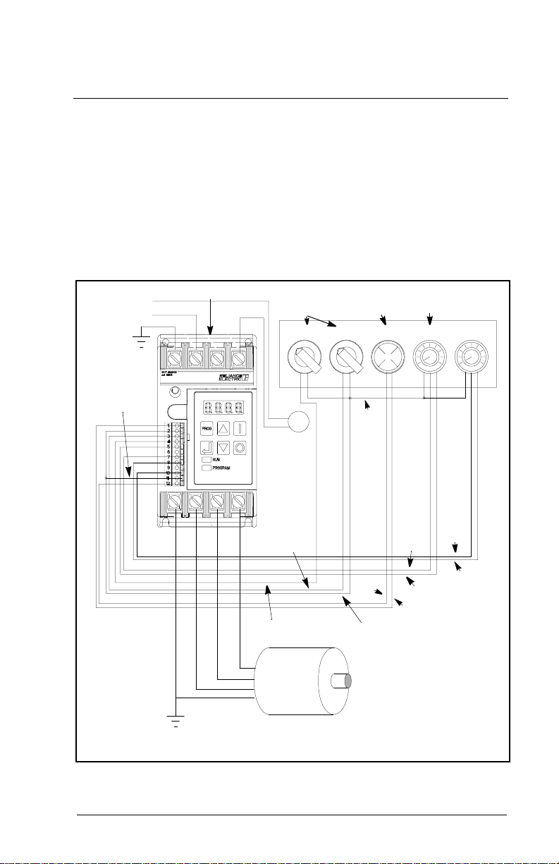
with the demo unit components and how the unit is wired.
2.1 Demo Unit Components and Wiring
115 VAC
GND
Gray
L1
L2
SP200 DRIVE
TOGGLE
SWITCHES
STOP RUN CONF IN
Fuse
Red
Orange
Motor
INDICATOR
LAMP
0 1
Brown
White
Brown
SPEED
POT
CONF OUT ANALOG
CHAN #1
R
Green
Ye l l o w
Black
Violet
ANALOG
CHAN #2
Blue
GND
Figure 2.1 – SP200 AC Drive Demo Components and Wiring
Setting Up the Demo Unit
2-1
Page 8

2.2 Connecting Power to the Demo Unit
The SP200 AC drive demo unit is powered by a grounded
115 VAC input. Follow these steps to connect the power cord
to the demo unit.
Step 1. Stand the demo unit on a flat surface with the
handle and cover latches facing you.
Step 2. Open both latches and lift the cover. Then slide the
cover to the right to remove.
Step 3. The power cord is stored in the cover of the demo
unit. Press down on the spring-loaded fasteners
inside the cover to access the power cord.
Step 4. Turn the demo unit around and stand it on its feet so
that it faces you.
Step 5. Plug the power cord into the receptacle on the left
side of the demo unit.
Step 6. Plug the power cord into a grounded 115 VAC
outlet.
Step 7. Use the on/off switch located next to the power cord
to apply power to the unit, if necessary.
2-2
Using the SP200 AC Drive Demo Unit
Page 9

C
HAPTER
Programming Basics
To program the drive for a specific application, you display
the appropriate parameter and adjust it as required. The
parameters are used to define characteristics of the drive.
3.1 Parameter Menu Structure
The SP200 drive has two kinds of parameters: program
parameters (P-xx), which configure the drive operation, and
display parameters (d-xx), which display information
regarding the drive status.
Table 3.1 – Parameter Organization
Range Parameter Group Parameter Type
3
P-00 to P-05
P-10 to P-13
P-20 to P-29
P-30 to P-38
P-40 to P-48
P-50 to P-55
P-60 to P-64
d-00 to d-09 Display Parameters Display Parameters
Protection
Digital Input/Output
Speed Reference
Dynamic Control
Fixed Speeds
V/Hz Curve
Utility
Program Parameters
3.2 Parameter Types
There are three types of parameters:
Tunable
•
drive is running or stopped.
Configurable
•
only while the drive is stopped.
Read-only
•
Programming Basics
parameters can be adjusted or changed while the
parameters can be adjusted or changed
parameters cannot be adjusted.
3-1
Page 10

3.3 How To Display and Adjust Parameter Values Using the Keypad
The keypad is located on the front panel of the drive demo
unit.
Table 3.2 – Keypad Description
1
9
2
8
3
7
4
6
5
The display shows either a parameter number or a parameter value.
1
The parameter numbers are preceded by either a “P-” or a “d-”.
2
3
4
5
6
3-2
PROG
The key toggles between display and program modes. The
PROGRAM LED
turns off when the drive is in display mode.
In display mode, the key scrolls through the display parameters.
In program mode, this key toggles between the parameter number
and parameter value.
The
RUN LED
or reverse direction. The
direction.
The
PROGRAM LED
turns off when the drive is in display mode.
In display mode, the key decrements the local speed reference.
In program mode, this key decrements the parameter number or
parameter value.
(5) turns on when the drive is in program mode and
turns on when the drive is running in either the forward
RUN LED
turns on when the drive is in program mode and
flashes while the drive is changing
Using the SP200 AC Drive Demo Unit
Page 11

Table 3.2 – Keypad Description
7
The key issues stop and fault reset commands to the drive.
8
The key issues start commands to the drive when
P-10 = 1.
9
In display mode, the key increments the local speed reference.
In program mode, this key increments the parameter number or
parameter value.
The following table provides detailed steps for keypad
operation.
Table 3.3 – Keypad Operation
Desired Action User Steps
Start the unit
Stop the unit
Increment the local
speed reference
Decrement the local
speed reference
View the value of
the present display
parameter
View the number of
the present display
parameter
Increment the
display parameter
number
Press to start the drive.
Note that for to work, a connection must be
present between terminals 2 and 3. In addition,
parameter P-10 must be set to 1.
Press to stop the drive.
While in display mode (
PROGRAM LED
is off), press
to increase speed.
While in display mode (
to decrease speed.
While in display mode (
PROGRAM LED
PROGRAM LED
is off), press
is off), the
value of the present display parameter is normally
displayed.
While in display mode (
PROGRAM LED
is off), press
and release once. The present display
parameter number will be displayed for 2 seconds.
The display will then return to the present
parameter value.
While in display mode (
PROGRAM LED
is off), press
until the desired parameter is displayed.
Following a 2-second delay, the parameter value
will be displayed.
Programming Basics
3-3
Page 12

Table 3.3 – Keypad Operation
Desired Action User Steps
Increment the
program parameter
number
Decrement the
program parameter
number
Increment the
current program
parameter value
Decrement the
current program
parameter value
Clear faults
1. Press until the
2. Press until the desired number is displayed.
1. Press until the
2. Press
1. Press until the
2. Press while the desired program parameter
3. Press until the desired value is displayed.
1. Press until the
2. Press while the desired program parameter
3. Press until the desired value is displayed.
Press
PROG
enter program mode.
PROG
enter program mode.
until the desired number is displayed.
PROG
enter program mode.
number is displayed.
PROG
enter program mode.
number is displayed.
.
PROGRAM LED
PROGRAM LED
PROGRAM LED
PROGRAM LED
turns on to
turns on to
turns on to
turns on to
3-4
Using the SP200 AC Drive Demo Unit
Page 13

C
HAPTER
4
Running the Demo Unit
The demo consists of five step-by-step labs to acquaint you
with the basic operation of the drive.
Purpose of the labs
Lab 1 This lab has two parts:
Lab 2 Learn how to use the display parameters
Lab 3 Learn how to use configured inputs and
Lab 4 Learn how to set up various stopping
Lab 5 Learn how to set up an avoidance
4.1 The Labs
:
a. Learn the steps required to reset the
drive to factory defaults.
b. Learn how to set up a basic
configuration that uses external I/O.
This lab sets the drive up for the next four
labs. Run Lab 1 first.
to view drive status.
outputs.
methods.
frequency.
Lab 1a: Resetting the drive to factory defaults.
Tools required
Step 1. Turn on the demo unit using the power switch.
Step 2. Press until the
Running the Demo Unit
: None
PROG
program mode.
PROGRAM LED
turns on to enter
4-1
Page 14

Step 3. Press or until P-60 [
displayed.
RESET TO DEFAULTS
] is
Step 4. Press
to display the value of P-60 (0 should be
displayed).
Step 5. Press to change the value to 1(Reset All Values
to Factory Defaults).
Step 6. Press to accept the value.
The drive’s factory defaults have been restored.
Lab 1b: Setting up a basic drive configuration that uses
external I/O control.
Step 1. Press until the
PROG
PROGRAM LED
turns on to enter
program mode.
Step 2. Press or until P-00 [
MINIMUM SPEED
] is
displayed.
Step 3. Press to display the value of P-00.
Step 4. Press or until the value 5 is displayed. This
sets the minimum speed to 5 Hz.
Step 5. Press to accept the value.
Step 6. Press until P-01 [
MAXIMUM SPEED
] is displayed.
4-2
Step 7. Press
to display the value of P-01.
Step 8. Press or to change the value to 60, if
necessary.
Step 9. Press to accept the displayed value.
Step 10. Repeat this process for all of the parameters listed
in table 4.2. The parameter settings are based on
the demo unit’s motor nameplate data listed below.
Note that the demo unit contains a Mode l C SP200 drive.
• 1600 RPM
• .22 A FLA
• 60 Hz
Using the SP200 AC Drive Demo Unit
Page 15

Table 4.1 – Parameter Values for Basic Configuration
No. Parameter Name Value
P-00
P-01
P-02
P-03
P-05
P-10
P-20
P-30
P-31
P-34
P-50
P-51
MINIMUM SPEED
MAXIMUM SPEED
MOTOR OVERLOAD CURRENT
REVERSE DISABLE
CURRENT LIMIT
START CONTROL
MAIN SPEED REFERENCE
ACCELERATION TIME
DECELERATION TIME
STOP CONTROL
BASE VOLTAGE
BASE SPEED
1 3.0 sec
1 3.0 sec
5 Hz
60 Hz
0.4 A
0
150%
2 (2-Wire Start)
0 (Analog Input 1)
0 (Ramp-to-Rest)
100 V
60 Hz
The drive is now programmed with a basic configuration that
uses external I/O control.
Step 11. Turn the
Step 12. Turn the
drive starts and the
Step 13. Turn the
CONF IN
STOP/RUN
ANALOG CHAN
switch to 1.
switch to
RUN LED
. Notice that the
RUN
turns on.
#1 switch (the main speed
reference) fully clockwise to run the drive at
maximum speed (60 Hz).
Step 14. Turn the
ANALOG CHAN
#1 switch fully
counter-clockwise to run the drive at minimum
speed (5 Hz).
Step 15. Turn the
STOP/RUN
switch to
to stop the drive.
STOP
Step 16. Change the value of parameter P-10 to 1 (Keypad
Control).
Step 17. Turn the
STOP/RUN
switch to
. Note that the drive
RUN
does not start because the start control is now the
keypad. Also notice that the
on.
Step 18. Turn the
Step 19. Press
turns on.
LED
RUN LED
STOP/RUN
.
switch to
STOP
Notice that the drive starts and the
does not turn
.
RUN
Step 20. Press to stop the drive.
Step 21. Change the value of parameter P-10 back to 2.
Running the Demo Unit
4-3
Page 16

Lab 2: Using the display parameters to view drive
status.
Tools required
Step 1. Press
: None
PROG
until the
PROGRAM LED
turns off to enter
display mode.
Step 2. Press once. The letter "d" will be displayed
along with a two-digit number.
Step 3. Continue to depress (multiple times) to cycle
through all the display parameters.
Note:
When you stop or pause at a display parameter for
more than 2 seconds, the value of that parameter is
displayed.
Step 4. Press
until parameter d-01 [
OUTPUT FREQUENCY
is displayed.
Step 5. Turn the
Step 6. Turn the
Step 7. Turn the
CONF IN
STOP/RUN
ANALOG CHAN
switch to 1.
switch to
RUN
.
#1 switch fully clockwise to
run the drive at maximum speed. The display
should read at or near 60.0 Hz.
Step 8. Turn the
ANALOG CHAN
#1 switch fully
counter-clockwise to run the drive at minimum
speed. The display should read 5.0 Hz.
]
Step 9. Press
Step 10. Turn the
Lab 3: Using configured inputs and outputs.
Tools required:
A configured input is an input that can be programmed to
perform various functions. On the demo unit, the
switch is wired as the configured input to terminals 2 and 6
on the drive’s terminal strip.
Running the Demo Unit
FREQUENCY
until parameter d-00 [
COMMAND
] is displayed. The display should read
5.0 Hz, which is the value of the main speed
reference,
STOP/RUN
ANALOG CHAN
#1.
switch to
to stop the drive.
STOP
None
CONF IN
4-4
Page 17

A configured output is an output that can be programmed to
indicate various conditions. On the demo unit, the red
indicator lamp is hardwired to the configurable output
OUT
CONF
terminals on the drive’s terminal strip (terminals 11 and 12).
In this lab, you will program the configured input as a function
loss interlock and as a reversing switch. You will program the
configured output to indicate various conditions.
Before proceeding with this lab, do the following:
Step 1. Be sure the drive is stopped and the
switch is in the
Step 2. Verify that P-10 [
position.
STOP
START CONTROL
] is set to 2. This
STOP/RUN
will set the start control to 2-wire control.
To set P-10, use the following procedure:
a. Press until the
PROG
PROGRAM LED
turns on.
b. Press or until P-10 is displayed.
c. Press
to display the value of P-10.
d. Press or until 2 is displayed.
e. Press to accept the value.
Lab 3a: Programming the input as a function loss
interlock.
A function loss is a hardwired input to the drive that can act
as an interlock from some other equipment. If that other
equipment fails or stop operating, this will cause a Function
Loss fault in the drive (fault code FL is displayed). This fault
will keep the drive from starting or will stop the drive if it is
operating.
The switch labeled
Step 1. Verify that the
Step 2. Verify that the
Step 3. Set P-11 [
Running the Demo Unit
position.
CONF IN
CONFIGURABLE INPUT
is wired as the configured input.
CONF IN
STOP/RUN
switch is in the 1 position.
switch is in the
STOP
] to 0 (Function Loss).
4-5
Page 18

Step 4. Turn the
rotate to the commanded speed selected on the
speed pot (
Step 5. Turn the
following things that occur:
• The drive faults, and the motor coasts to a stop.
• The drive displays the fault code FL (Function
Loss).
STOP/RUN
ANALOG CHAN
CONF IN
switch from 1 to 0. Note the
switch to
#1).
. The motor should
RUN
• The drive status
changes from green (OK) to
LED
red (problem exists).
• The
Step 6. Turn the
STOP/RUN
and
RUN
CONF IN
PROGRAM LED
switch back to 1, and turn the
switch back to
s turn off.
. Notice that nothing
STOP
happens because the fault condition prohibits the
drive from running.
Step 7. Press to reset the fault and note the following:
• The FL fault code is not displayed.
• The drive status
changes from red to green.
LED
Lab 3b: Programming the input as a reversing switch.
Step 1. Set P-11 [
CONFIGURABLE INPUT
] to 1. This programs
the drive to run in the opposite direction when the
configurable input is on.
Step 2. Verify that the
position and that the
STOP/RUN
switch is in the
CONF IN
switch is in the 0
STOP
position.
Step 3. Turn the
direction of motor rotation. Turn the
to
STOP
STOP/RUN
to stop the drive.
switch to
, and notice the
RUN
STOP/RUN
switch
Step 4. Turn the
Important:
Running the Demo Unit
CONF IN
switch to 1, and notice that the
direction of motor rotation is reversed. Turn the
CONF IN
switch to 0 to stop the drive.
If you set the
CONF IN
STOP/RUN SWITCH
switch is set to 1, or vice versa, a drive
to
while the
RUN
fault will occur and CF will be displayed. The
drive stops if more than one input (forward,
reverse, or jog) is on.
4-6
Page 19

If this fault occurs, turn the
and the
STOP
to reset the fault.
CONF IN
STOP/RUN
switch to 0. Then press
Lab 3c: Programming the configurable output.
switch to
The red indicator lamp (
CONF OUT
) on the demo unit is
hardwired to the configurable output on the terminal strip
(terminals 11 and 12).
Step 1. Set P-12 [
CONFIGURABLE OUTPUT
] to 0 (No Fault).
This programs the output to turn on when the drive
is not faulted.
Step 2. Turn the
STOP/RUN
switch to
. (The motor should
RUN
rotate).
Step 3. Turn the
CONF IN
switch to 1. Notice the drive now
displays a CF fault code. Also note that the red
indicator lamp is off.
Step 4. Turn the
switch to
CONF IN
STOP
switch to 0, and the
.
RUN/STOP
Step 5. Press to reset the fault. Notice that the CF
code on the display is gone, and the red indicator
lamp is now on.
Step 6. Set P-12 to 2 (Running). This programs the output
to turn on when the drive is commanded to run.
Step 7. Turn the
Turn the
STOP/RUN
CONF IN
switch to
, then back to
RUN
STOP
switch to 1, then back to 0. Notice
when the red indicator lamp turns on and off.
Step 8. Set P-12 to 3 (At Frequency). This programs the
configured output to turn on when the output from
the drive equals the speed set by the speed
reference pot,
ANALOG CHAN
#1 (commanded
frequency speed).
Step 9. Turn the
STOP/RUN
switch to
. Notice that the red
RUN
indicator lamp does not turn on immediately, but
remains off until the output is equal to the speed
reference. Rotate the speed pot clockwise and
counter-clockwise and watch the red indicator lamp.
.
Step 10. Set P-12 to 4 (Above Frequency). This programs
Running the Demo Unit
the configured output to turn on when the drive
exceeds a specified frequency.
4-7
Page 20

Step 11. Set P-13 [
CONFIGURABLE OUTPUT LEVEL
This sets the level at which the output will turn on to
30.0 Hz.
Step 12. Turn the speed pot (
clockwise. The red indicator lamp should be on.
ANALOG CHAN
] to 30.0.
#1) fully
Step 13. Press to enter display mode.
Step 14. Press
PROG
until d-01 [
OUTPUT FREQUENCY
] is
displayed.
Step 15. Slowly turn the speed pot counter-clockwise. Notice
that the red indicator lamp turns off when the
frequency drops below 30.0 Hz.
Step 16. Set the s
TOP/RUN
switch to
STOP
.
Lab 4: Programming various stopping methods.
Tools required:
None
This lab consists of three parts:
a. Programming the drive for a coast-to-rest stop.
b. Programming the drive for a ramp-to-rest stop.
c. Programming the drive for DC injection braking.
Lab 4a: Programming the drive for a coast-to-rest stop.
Step 1. Press until the
PROG
PROGRAM LED
turns on to enter
programming mode.
Step 2. Press or until P-34 [
STOP CONTROL
] is
displayed.
Step 3. Press to display the value of P-34.
Step 4. Set P-34 to 1 (Coast-to-Rest).
Step 5. Turn the
Step 6. Press to enter display mode.
Running the Demo Unit
Note:
The drive may be at the default value of 0
(Ramp-to-Rest), which means the output voltage
and frequency is lowered based on the decel time.
During the previous labs, you may have noticed
how quickly the drive stopped.
pot (
ANALOG CHAN
PROG
STOP/RUN
switch to
#1) fully clockwise.
and turn the speed
RUN
4-8
Page 21

Step 7. Press , if necessary, until d-01 [
FREQUENCY
] is displayed.
COMMAND
Step 8. Turn the
STOP/RUN
switch to
. Notice that the
STOP
output frequency immediately drops to 0. Notice
how long it takes the motor to stop.
Lab 4b: Programming the drive for a ramp-to-rest stop.
Step 1. Press to enter program mode.
PROG
Step 2. Set P-34 to 0 (Ramp-to-Rest).
Step 3. Press to enter display mode.
PROG
Step 4. Press , if necessary, until the value of d-01
[
COMMAND FREQUENCY
Step 5. Turn the
STOP/RUN
] is displayed.
switch to
RUN. ANALOG CHAN
#1
should be turned fully clockwise. Wait for the drive
to reach full speed.
Step 6. Turn the
STOP/RUN
switch to
. Notice that the
STOP
output frequency and voltage decreases over time
(ramps down) to zero.
Lab 4c: Programming the drive for DC injection braking.
DC injection braking is a stopping method whereby DC
current is applied to a single winding in a motor.
Step 1. Set P-34 to 2 (DC Injection).
Step 2. Set P-35 [
Step 3. Set P-36 [
Step 4. Press to enter display mode.
Step 5. Press , if necessary, until the value of d-01
Step 6. Turn the
Running the Demo Unit
DC BRAKE CURRENT
] to 100. This specifies
the output current level in percent.
DC BRAKE TIME AT STOP
] to 3.0. This sets
the amount of time in seconds that the current
specified in P-35 is applied to the motor. The DC
injection begins when the drive is commanded to
stop.
PROG
[
COMMAND FREQUENCY
STOP/RUN
] is displayed.
switch to
RUN. ANALOG CHAN
#1
should be turned fully clockwise. Wait for the drive
to reach full speed.
4-9
Page 22

Step 7. Turn the
STOP/RUN
switch to
. Notice that the
STOP
output frequency and voltage dropped to 0
immediately.
Step 8. Reset the following parameters:
P-34 to 1
P-35 to 10
P-36 to 0.0
Lab 5: Setting up an avoidance frequency.
Tools required:
None
Avoidance frequency parameters are used to prevent the
drive from continuous operation within a range (band) of
frequencies.
Step 1. Set P-37 [
AVOIDANCE FREQUENCY
] to 30.0 Hz. This
specifies the midpoint of the band.
Step 2. Set P-38 [
AVOIDANCE FREQUENCY BAND
] to 20.0 Hz.
This sets the width of the band. In this case, the
width of the band is set from 20.0 Hz to 40.0 Hz.
Step 3. Turn the speed pot to zero (
ANALOG CHAN
#1 should
be turned fully counter-clockwise).
Step 4. Press to enter display mode. Press , if
necessary, until the value of d-01 [
FREQUENCY
Step 5. Turn the
PROG
] is displayed.
STOP/RUN
switch to
RUN
COMMAND
.
Step 6. Slowly turn the speed pot clockwise, and watch the
display.
Notice that the motor holds up at 20.0 Hz and
speeds up at 40.0 Hz.
Step 7. Press until d-00 [
COMMAND FREQUENCY
] is
displayed.
Step 8. Turn the speed pot to zero, and then slowly turn the
speed pot up and down.
Step 9. Reset the following parameters:
Step 10. Turn the
Running the Demo Unit
Notice when the motor increases in speed, holds
speed, and decreases speed.
P-37 to 0
P-38 to 0
RUN/STOP
switch to
STOP
.
4-10
Page 23

C
HAPTER
5
Troubleshooting
the Demo Unit
Use table 5.1 to troubleshoot any problems you may have
with the demo unit.
For technical assistance, call 1-800-726-8112.
Table 5.1 – Troubleshooting Table
Problem Corrective Action
Display or
are not on.
Demo unit does
not react as
described in labs.
Cannot change
parameter value.
Fault or alarm
code is displayed.
LED
s
• Check power source.
• Check power cord connection.
• Check on/off switch.
• Check fuse.
• Verify that parameter defaults
were restored.
• Verify that parameters were set
correctly.
• If the drive is running, verify that
the parameter is a tunable
parameter.
• Refer to the troubleshooting
section in Installing and Operating
the SP200 AC Drive (D2-3408).
Troubleshooting the Demo Unit
5-1
Page 24

5-2
Using the SP200 AC Drive Demo Unit
Page 25

Page 26

U.S. Drives Technical Support
Tel: (1) 262.512.8176, Fax: (1) 262.512.2222, Email: support@drives.ra.rockwell.com, Online: www.ab.com/support/abdrives
Publication D2-3474– November 2000 Copyright © 2000 Rockwell Automation, Inc. All Rights Reserved. Printed in USA.
 Loading...