

Page 1
Installation Instructions
Filter Capacitor Replacement Kit SK-L1-CAP2-D650 for PowerFlex 700L Frame 3A 480V AC Drives
Catalog Number
SK-L1-CAP2-D650
Additional Resources
Top ic Pag e
Additional Resources 1
What the Kit Contains 2
Too ls Tha t Yo u Ne ed 3
Precheck 3
Wh at Yo u Nee d To D o 4
Step 1: Disconnect and Lock Out Input Power at the Branch Circuit 4
Step 2: Turn Off the Drive Enclosure Circuit Breaker 4
Step 3: Verify that DC Bus Capacitors are Discharged 5
Step 4: Prepare for the Replacement 5
Step 5: Remove the Existing Filter Capacitor Assembly 6
Step 6: Install the New Filter Capacitor Assembly 7
Step 7: Power Up the Drive and Filter Capacitor Assembly Replacement 8
These documents contain additional information concerning related products
from Rockwell Automation.
Publication 20L-IN015A-EN-P - February 2012
Resource Description
PowerFlex 700L Frame 3A and 3B Hardware Service
Manual, publication 20L-TG001
PowerFlex 700L Liquid-Cooled AC Drive User Manual,
publication 20L-UM001
Product Certifications website, http://www.ab.com
You can view or download publications at http://
www.rockwellautomation.com/literature/. To order paper copies of technical
documentation, contact your local Allen-Bradley distributor or Rockwell
Automation sales representative.
Provides detailed hardware service information.
Provides drive installation and operating information.
Provides declarations of conformity, certificates, and other
certification details.
Page 2
Filter Capacitor Replacement Kit SK-L1-CAP2-D650 for PowerFlex 700L Frame 3A 480V AC Drives
ATT EN TI ON : Only qualified electrical personnel familiar with the construction
and operation of this equipment and the hazards involved should install, adjust,
operate, or service this equipment. Read and understand this procedure in its
entirety before proceeding.
ATT EN TI ON : Do not remove the existing filter capacitor assembly or install the
replacement kit with power applied to the drive. Disconnect, lock out, and tag
all incoming power to the drive enclosure before attempting such removal or
installation. Failure to observe this precaution could result in severe bodily
injury or loss of life.
ATT EN TI ON : DC bus capacitors retain hazardous voltages after input power has
been disconnected. After disconnecting input power, wait five (5) minutes for
the DC bus capacitors to discharge and then check the voltage with a voltmeter
to ensure that the DC bus capacitors are discharged before touching any internal
components. Failure to observe this precaution could result in severe bodily
injury or loss of life.
ATT EN TI ON : The user is responsible for conforming with all applicable local,
national, and international codes. Failure to observe this precaution could result
in damage to, or destruction of, the equipment.
What the Kit Contains
ATT EN TI ON : The drive contains ESD- (Electrostatic-Discharge) sensitive parts
and assemblies. Static control precautions are required when installing, testing,
servicing or repairing the drive. Component damage may result if ESD control
procedures are not followed. If you are not familiar with static control
procedures, refer to Allen Bradley publication 8000-4.5.2, “Guarding Against
Electrostatic Damage” or any other applicable ESD protection handbook.
• One Capacitor Bank Assembly
• One Bag of Hardware
Kit Weight
12.7 kg (28 lb)
2 Rockwell Automation Publication 20L-IN015A-EN-P - February 2012
Page 3
Filter Capacitor Replacement Kit SK-L1-CAP2-D650 for PowerFlex 700L Frame 3A 480V AC Drives
Tools That You Need
Precheck
• Properly-rated, isolated multi-meter (DMM) to measure the AC input
and DC filter capacitor voltages (working voltage specifications should be
1000V)
• 3/8-inch drive ratchet
• 3/8-inch drive 10 mm deep well socket
• 3/8-inch drive 3/4-inch deep well socket
• Torque wrench capable of 50 lb•in (5.6 N•m)
• Torque wrench capable of 35 lb•ft (47.5 N•m)
• 10 mm box wrench
• #1 Phillips screwdriver
• Small wire cutter
• Lockout/Tagout kit
• Wor k g lo ve s
• Arc Flash Gear
You may also need a box or container to hold loose hardware.
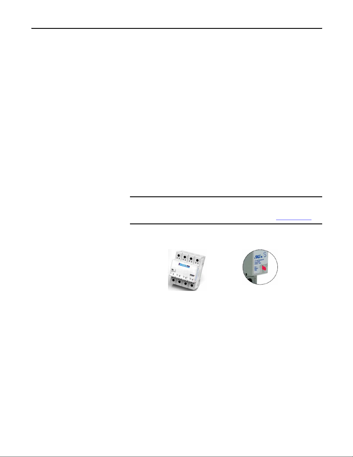
IMPORTANT
Inspect the surge trap (SPD) in the drive and note whether the visual
inspection tab has been activated. This indicates internal damage and the need
for replacement. For the location of the surge trap, see Figure 1 on page 5
.
Visual Inspection Tab DetailSurge Trap (SPD) in Drive
Drives built prior to May 2008 had older style SPDs mounted on the filter
capacitor bank assemblies. If a surge trap style SPD is not installed in the drive, it
is necessary to order and install a surge trap upgrade kit, Catalog Number 21T385253-A01 to insure there is proper transient protection for the equipment.
Rockwell Automation Publication 20L-IN015A-EN-P - February 2012 3
Page 4

Filter Capacitor Replacement Kit SK-L1-CAP2-D650 for PowerFlex 700L Frame 3A 480V AC Drives
What You Need To Do
Step 1: Disconnect and Lock
Out Input Power at
the Branch Circuit
To install the filter capacitor assembly replacement kit you need to:
Step 1: Disconnect and lock out input power at the branch circuit.
Step 2: Turn off the drive enclosure circuit breaker.
Step 3: Verify that DC bus capacitors are discharged.
Step 4: Prepare for the replacement.
Step 5: Remove the existing filter capacitor assembly.
Step 6: Install the new filter capacitor assembly.
Step 7: Power up the drive and filter capacitor assembly replacement.
Disconnect input power upstream of the drive assembly enclosure. Follow
required safety procedures to turn off and lock out input power during the repair.
L1 L2 L3
I
Step 2: Turn Off the Drive
Enclosure Circuit
Breaker
O
Turn off the drive enclosure circuit breaker and open the drive enclosure
door.
4 Rockwell Automation Publication 20L-IN015A-EN-P - February 2012
Page 5

Filter Capacitor Replacement Kit SK-L1-CAP2-D650 for PowerFlex 700L Frame 3A 480V AC Drives
Step 3: Verify that DC Bus
Capacitors are
Discharged
Step 4: Prepare for the
Replacement
ATT EN TI ON : DC Bus capacitors retain hazardous voltages after input power has
been disconnected. After disconnecting input power, wait five (5) minutes for
the DC bus capacitors to discharge and then check the voltage with a voltmeter
to ensure that the DC bus capacitors are discharged before touching any internal
components. Failure to observe this precaution could result in severe bodily
injury or loss of life.
a. Using a confidence-tested AC voltmeter, verify that AC power is no
longer present on the line side of the drive enclosure's main incoming
circuit breaker.
b. Visually inspect the drive to insure no lamps or indicators are
illuminated.
a. Read and follow the lock out, tag out, and safety verifications previously
described.
b. Open the door of the drive. Refer to Figure 1
the hardware in the existing Filter Capacitor Assembly.
IMPORTANT
Prior to the removal and installation process, it is highly recommended that the
left side panel of the enclosure be removed to gain proper access to the
capacitor bank assembly. If the left side panel cannot be removed, please call
Technical Support for assistance at 1-440-646-3434.
and note the locations of
Figure 1 - Existing Filter Capacitor Assembly in Drive
Surge Trap (SPD) Ground Wire Connection
(follow wire to the surge trap)
Bleeder Resistors (3x)
Resistor Mounting
Hardware (6x)
1 μF Capacitor Ground
Lead Connection
Power Wires
(3x, not shown)
Capacitor Bank
Hardware (6x)
Tab Connectors (3x)
Neutral Bus Plate
Rockwell Automation Publication 20L-IN015A-EN-P - February 2012 5
Page 6

Filter Capacitor Replacement Kit SK-L1-CAP2-D650 for PowerFlex 700L Frame 3A 480V AC Drives
Step 5: Remove the
Existing Filter
Capacitor Assembly
ATT EN TI ON : Upon removing the assembly and hardware, sharp edges may be
encountered. Use work gloves to protect your hands.
a. After power has been removed from the drive, the filter capacitor bank
should discharge via the bleeder resistor discharge network. Wait five
(5) minutes to fully discharge.
b. Carefully check for zero (0) volts between each of the three (3)
Capacitor Bus Bars (input power) and the Neutral Bus Plate at the
stake-on connectors using a confidence-tested DC voltmeter.
c. Gain access to the left side of the enclosure. Remove and retain the
hardware that secures the left side panel to the enclosure, and remove
the panel and set it aside.
d. Cover any components under the capacitor bank to protect them from
any dropped hardware.
e. Place a piece of rigid cardboard or something similar on top of the three
(3) Bus Bars connected to the contactors to prevent any damage to the
Bus Bars or their protective coating.
f. Using access from the left side of the enclosure, locate the three (3)
power wires coming from the back of the capacitor bank assembly that
are attached to the inductors. Remove the hex nuts securing the power
wires to the inductors. Retain the hardware.
g. Remove the six (6) screws that are securing the three (3) bleeder
resistors to the sheet metal panel. Discard the hardware.
h. Remove the grounding screw that is securing the ground lead from the
surge trap (SPD) to the sheet metal panel. Discard the hardware.
i. Remove the grounding screw that is securing the ground lead from the
1 μF Capacitor to the sheet metal panel. Discard the hardware.
j. Remove the hardware that is securing the capacitor bank assembly to
the mounting panel and carefully remove the capacitor bank assembly
from the enclosure. Once removed, remove the hardware that is
securing the three (3) power wires to the back of the capacitor bank
assembly. Note the location of each of the wires. Retain the hardware
and the wires.
6 Rockwell Automation Publication 20L-IN015A-EN-P - February 2012
Page 7

Filter Capacitor Replacement Kit SK-L1-CAP2-D650 for PowerFlex 700L Frame 3A 480V AC Drives
Step 6: Install the New
Filter Capacitor
Assembly
ATT EN TI ON : Upon installing the assembly and hardware, sharp edges may be
encountered. Use work gloves to protect your hands.
a. Attach the three (3) power wires that were removed in Step 5-j to the
back of the new capacitor bank assembly. Tighten to 45…50 lb•in
(5.1…5.6 N•m).
b. Place the new capacitor bank assembly up to the mounting panel and
secure the assembly in place with hardware removed in Step 5-j.
Tighten screws only finger-tight until all hardware is in place and then
fully tighten.
c. Using access from the left side of the enclosure, reattach the three (3)
power wires to the inductor using the hardware removed in Step 5-f.
Tighten to 30…35 lb•ft (40.7…47.5 N•m).
d. Secure the three (3) bleeder resistors to the sheet metal panel using six
(6) M3 x 8 pan head screws (supplied with kit).
e. Secure the ground lead from the 1 μF Capacitor in the location shown
in Figure 2
f. Insure that the surge trap style SPD, shown in the “Precheck”
section on page 3
Figure 2 - Replacement Filter Capacitor Assembly (shown installed on drive)
using one (1) M6 x 16 hex head screw (supplied with kit).
, is installed and reconnected properly.
Bleeder Resistors (3x) Resistor Mounting Hardware (6x)
1 μF Capacitor
1 μF Capacitor Ground
Lead Connection
Power Wires
(3x, not shown)
Capacitor Bank
Hardware (6x)
Rockwell Automation Publication 20L-IN015A-EN-P - February 2012 7
Page 8

Filter Capacitor Replacement Kit SK-L1-CAP2-D650 for PowerFlex 700L Frame 3A 480V AC Drives
Step 7: Power Up the Drive
and Filter Capacitor
Assembly
Replacement
Normal power-up and recommissioning procedures should be followed to ensure
electrical integrity prior to applying power and verifying drive operation.
a. Verify that all tools, hardware, and cardboard or covers have been
removed from the drive enclosure.
b. Re-install the left side panel to the enclosure.
c. Complete normal pre-power-up checks.
d. With the drive enclosure door closed, remove the lock and tag, and
apply power to the drive enclosure.
e. Turn on the drive enclosure circuit breaker.
f. Verify normal drive operation.
U.S. Allen-Bradley Drives Technical Support - Tel: (1) 262.512.8176, Fax: (1) 262.512.2222, E-mail: support@drives.ra.rockwell.com
Online: www.ab.com/support/abdrives
Allen-Bradley, Rockwell Software, Rockwell Automation, and TechConnect are trademarks of Rockwell Automation, Inc.
Trademarks not belonging to Rockwell Automation are property of their respective companies.
Publication 20L-IN015A-EN-P - February 2012 PN-130084
- Copyright © 2012 Rockwell Auto mation, Inc. All rights reserved. Pr inted in the U.S.A.
 Loading...