

Page 1
Installation Instructions
PowerFlex 700 Phase Monitor Relay Replacement
SK-G9-RELAY-F9
This publication provides the steps needed to replace a PowerFlex 700 Frame 9
Phase Monitor Relay. This relay verifies correct phasing of the three-phase blower
that is used for drive cooling.
Before proceeding, read the following:
ATTENTION: This drive contains ESD (Electrostatic Discharge) sensitive
parts and assemblies. Static control precautions are required when
installing, testing, servicing or repairing this assembly. Component
damage may result if ESD control procedures are not followed. If you are
not familiar with static control procedures, reference Guarding Against
Electrostatic Damage, publication 8000-4.5.2 or any other applicable ESD
protection handbook.
ATTENTION: Only qualified personnel familiar with adjustable frequency
AC drives and associated machinery should perform maintenance/repair of
the system. Failure to comply may result in personal injury and/or
equipment damage.
ATTENTION: To avoid an electric shock hazard, verify that the voltage on
the bus capacitors has discharged before performing any work on the
drive. Measure the DC bus voltage at the +DC & –DC terminals of the
Power Terminal Block (refer to the User Manual for location). The voltage
must be zero.
For additional PowerFlex 700 drive information, refer to the following
publications online at: www.rockwellautomation.com/literature.
Title Publication
PowerFlex 700 Series B User Manual 20B-UM002
Frame 7-10 Installation Instructions 20B-IN014
Wiring and Grounding Guidelines for PWM AC Drives DRIVES-IN001
Preventive Maintenance of Industrial Control and Drive System Equipment DRIVES-TD001
Safety Guidelines for the Application, Installation and Maintenance of Solid
State Control
A Global Reference Guide for Reading Schematic Diagrams 100-2.10
Guarding Against Electrostatic Damage 8000-4.5.2
SGI-1.1
To order paper copies of technical documentation, contact your local Rockwell
Automation distributor or sales representative. To find your local distributor or
sales representative, visit www.rockwellautomation.com/locations
For Drives Technical Support see www.ab.com/support/abdrives
.
.
20B-IN027A-EN-P
Page 2
PowerFlex 700 Phase Monitor Relay Replacement
Type A
Drives Manufactured before January 20, 2011
(see below)
Type B
Drives Manufactured January 20, 2011 and after
(see page 3
)
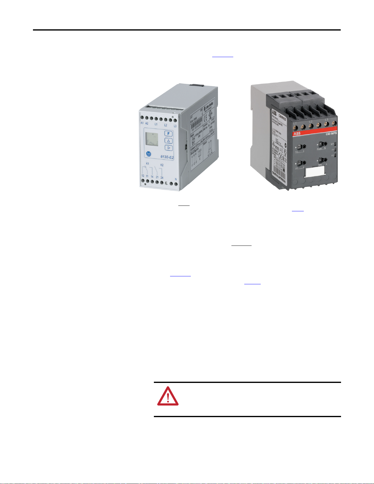
Identifying the Relay
Two types of Phase Monitor Relays are used in Frame 9 drives depending on the
date of manufacture. Refer to Figure 1
and determine the relay type currently
installed in your drive. Next, locate the corresponding replacement procedure.
Figure 1 - Relay Identification
Replacing the Relay
Type A - Drives Manufactured before January 20, 2011
1. Verify that all power to the drive has been removed.
2. Usi ng Figure 1
A.” If not, refer to the procedure on page 3
3. Locate terminals L1, L2 and L3 on the existing relay. Verify that the wires
connected to each terminal are labeled correctly, then remove the wires.
4. Cut and insulate the two wires connected to A1 and A2. These wires will
not be used with the replacement relay. Ensure that the wire ends are well
insulated using wire nuts and tape. Secure the loose ends to the wire
harness.
5. The wires just cut and insulated are routed to the “120V” and “N”
terminals of TB-9. Trace these wires back to TB-9 and disconnect. Insulate
the ends and secure to the wire harness.
, verify that the relay installed in your drive matches “Type
.
ATTENTION: To guard against possible equipment damage and/
or personal injury, ensure that the wires previously disconnected
from the relay and TB-9 are thoroughly insulated (using wire nuts
and tape) and secured to the wire harness.
2 Rockwell Automation Publication 20B-IN027A-EN-P - March 2011
6. Remove the wire connected to terminal 21 of the relay. Relabel this wire
“25.”
Page 3

PowerFlex 700 Phase Monitor Relay Replacement
➊
➍
➌
➋
➎
7. Remove the wire connected to terminal 24 of the relay. Relabel this wire
“28.”
8. Remove the end clamps from the DIN rail. Remove the relay and discard.
9. Mount the new relay to the DIN rail and install end clamps.
10. Connect wire numbers 25 and 28 to the corresponding terminals of the
new relay.
11. Connect the L1, L2 and L3 wires to the corresponding terminals of the
new relay.
12. Verif y the fo llo wi ng a dj us tm ents :
No.
(see Figure 2
) Adjustment Setting
➊ DIP Switches OFF
➋ Overvoltage Threshold Set to maximum (580V)
➌ Undervoltage Threshold Set to minimum (350V)
➍ Phase Unbalance Threshold Set to maximum (25%)
➎ Delay Set to minimum (0 s)
Figure 2 - Replacement Relay Adjustments
L1 L2 L3
580
UV
350
UV
16
15 18 26 25 28
15
Asym. %
6
Time s
R/T
F1
F2
43 21
ON
OFF
13. Apply power and check for proper operation.
If phasing is correct, the “R/T” LED will illuminate.
If phasing is not correct, the “F1” and “F2” LEDs will alternately
illuminate. Refer to the PowerFlex 700 Frame 7…10 Installation
Instructions, publication 20B-IN014 for troubleshooting information.
Type B - Drives Manufactured January 20, 2011 and after
1. Verify that all power to the drive has been removed.
2. Usi ng Figure 1
B.” If not, refer to the procedure on page 2
Rockwell Automation Publication 20B-IN027A-EN-P - March 2011 3
, verify that the relay installed in your drive matches “Type
.
Page 4

PowerFlex 700 Phase Monitor Relay Replacement
www.rockwellautomation.com
Americas: Rockwell Automation, 1201 South Second Street,
Milwaukee, WI 53204-2496 USA,
Tel:
(1) 414.382.2000, Fax: (1) 414.382.4444
Europe
/
Middle East/Africa: Rockwell Automati
on,
Pegasus Park, De Kleetlaan 12a,
1831 Diegem, Belgium,
Tel: (32) 2 663 0600, Fax: (32) 2 663 0640
Asia Pacific: Rockwell Automation, Level 14, Core F, Cyberport 3, 100 Cyberport Road, Hong Kong, Tel: (852) 2887 4788, Fax: (852) 2508 1846
Power, Control and Information Solutions Headquarters
*PN-111987*
PN-111987
3. Locate terminals L1, L2 and L3 on the relay. Verify that the wires
connected to each terminal are labeled correctly, then remove the wires.
4. Locate the wires connected to terminals 25 and 28 of the relay and verify
that they are labeled correctly. Remove the wires from the relay.
5. Remove the end clamps from the DIN rail. Remove the relay and discard.
6. Mount the new relay to the DIN rail and install end clamps.
7. Connect wire numbers 25 and 28 to the corresponding terminals of the
new relay.
8. Connect the L1, L2 and L3 wires to the corresponding terminals of the
new relay.
9. Verif y the fo llo wi ng a dj us tm ents :
No.
(see Figure 2
) Adjustment Setting
➊ DIP Switches OFF
➋ Overvoltage Threshold Set to maximum (580V)
➌ Undervoltage Threshold Set to minimum (350V)
➍ Phase Unbalance Threshold Set to maximum (25%)
➎ Delay Set to minimum (0 s)
10. Apply power and check for proper operation.
If phasing is correct, the “R/T” LED will illuminate.
If phasing is not correct, the “F1” and “F2” LEDs will alternately
illuminate. Refer to the PowerFlex 700 Frame 7…10 Installation
Instructions, publication 20B-IN014 for troubleshooting information.
U.S. Allen-Bradley Drives Technical Support - Tel: (1) 262.512.8176, Fax: (1) 262.512.2222, E-mail: support@drives.ra.rockwell.com,
Online: www.ab.com/support/abdrives
Publication 20B-IN027A-EN-P – March 2011 PN-111987
Copyright © 2011 Rockwell Automation, Inc. All rights reserved. Printed in USA.
 Loading...