

Page 1
SIPHA 2
(b) Description
The Sipha 2 is a magnetically actuated non-contact guard interlock
switch. The system is self monitoring and comprises a coded
magnetic actuator and sensor connected via two wiring channels to a
control unit. THE SENSOR HEAD MUST NOT BE USED WITHOUT THE
CONTROL UNIT.
RETAIN THESE INSTRUCTIONS
Installation must be in accordance with the following steps and must be carried
out by suitably competent personnel.
This device is intended to be part of the safety related control system of a
machine. Before installation, a risk assessment should be performed to determine
whether the specifications of this device are suitable for all foreseeable
operational and environmental characteristics of the machine to which it is to be
fitted.
At regular intervals during the life of the machine check whether the
characteristics foreseen remain valid and inspect this device for evidence of
accelerated wear, material degradation or tampering. If necessary the device
should be replaced . Guardmaster cannot accept responsibility for a failure of this
device if the procedures given in this sheet are not implemented or if it is used
outside the recommended specifications in this sheet.
The interlock is not to be used as a mechanical stop.
Guard stops and guides must be fitted.
Exposure to shock and/or vibration in excess of those stated in
IEC 68 part: 2-6/7 should be prevented.
Adherence to the recommended inspection and maintenance instructions forms
part of the warranty.
When a single sensor is connected to the control unit a single safety related fault
at the sensor, connecting wiring or inside the control unit will be detected either
immediately or at the next opening of the guard (depending on the type of
fault). When the fault is detected the control unit goes to a lock out condition. The
output contacts will not close until the fault has been rectified.
If multiple sensors are connected to the control unit each guard door should be
opened and then shut individually.
Otherwise some single faults may not be detected and unintentional lockout reset
may occur if two or more guard doors are open at the same time.
Deutsch /
1
(c) Abstand (mm) Magnetfläche zu
Magnetfläche /
(d) Versatztoleranz (mm) /
Tolérance de défaut d'alignement (mm).
(i) Sensor /
(j) Betätiger /
(g) Schutztür-Arretierungen /
2
(b) Rückansicht /
(c) Auf 35mm DIN-Schiene montieren /
Monter sur rail DIN de 35mm.
(d) In Gehäuse nach mindestens IP 54
einbauen /
IP54 minimum.
(e) Anschlüsse
ANMERKUNG: Der Eingangszustand liegt
vor, wenn sich der Betätiger innerhalb des
vorgegebenen Schaltabstandes befindet.
A1 & A2 = Spannungsversorgung 110/230 V
(wählbar)
+ & - = Einspeisung 24V AC/DC
1 = Eingang (Ruhekontakt) BLAU vom Sensor
2 = Eingang (Arbeitskontakt) GELB vom Sensor
3 = Eingang (Arbeitskontakt) GRÜN vom Sensor
4 = Eingang (Rukekontakt) ROT vom Sensor
X1 & X2 = Schützüberwachung/Rückstellung
13 & 14 = Schutzausgang 1 (Arbeitskontakt)
21 & 22 = Hilfsausgang 1 (Ruhekontakt) /
Connexions
REMARQUE: l’état de l’entrée est décrit lorsque la
commande est située dans les limites de la
distance d’utilisation assurée.
A1 et A2 = alimentation 110 / 230 V commutable
+ & - = alimentation : 24V c.a./c.c.
1 = Entrée (N/F) du contact, BLEUE
2 = Entrée (N/O) du contact, JAUNE
3 = Entrée (N/O) du contact, VERTE
4 = Entrée (N/F) du contact, ROUGE
X1 et X2 = contrôle/réarmement du contacteur
13 et 14 = sortie de sécurité 1 (N/O)
21 et 22 = sortie auxiliaire 1 (N/F)
(f) LED-Anzeige
STROM EIN(ROT)-Leuchtet auf wenn das Gerät
Strom hat
AUSGANG(GRÜN)-Leuchtet auf wenn
Ausgangskontakte geschlossen sind /
Voyant
POWER (rouge)- est allumé lorsque l'appareil
est sous tension
OUTPUT (vert)- s'allume lorsque les contacts
de sortie sont fermés
(g) Spanning abschalten /
Français
Distance face à face (mm).
Contact.
Emetteur.
Vue postérieure.
A monter dans coffret
Isoler les alimentations
Butées de porte.
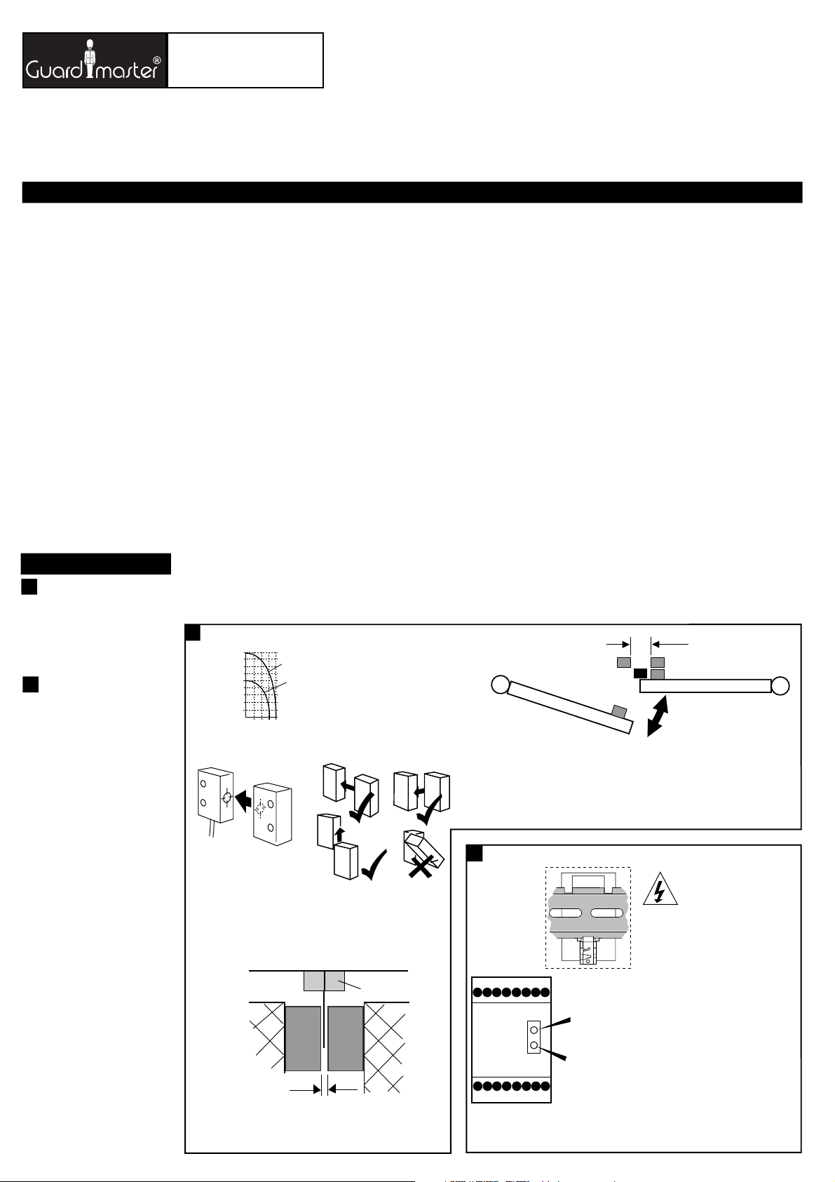
(a) Sensor / Sensor / Contact
1
9
5
distance (mm)
(c) Face to face
0mm
3
(d) Misalignment
tolerance (mm)
(e)
Operation: target face to target face
Betriebsposition: Zielscheiben gegenüber
Mise en œuvre : cibles face à face
NOTE: ACTUATOR MUST NOT STRIKE SENSOR
(f)
ANMERKUNG: DER BETÄTIGER DARF DEN SENSOR NICHT BERÜHREN
REMARQUE : L'EMETTEUR NE DOIT PAS HEURTER LE CONTACT
min 1mm
max 3mm - type 1
max 4mm - type 2
Recommended gap between sensor and actuator.
(h)
Einbauposition: Magnetflächen gegenüberliegend.
Espace recommandé entre l'émetteur et le récepteur.
(a) CODED MAGNETIC INTERLOCK SWITCH & CONTROL UNIT
CODIERTER, MAGNETISCH BETÄTIGTER SICHERHEITSSCHALTER & STEUERGERÄT
INTERVERROUILLAGE A CODAGE MAGNÉTIQUE & BLOC LOGIQUE DE CONTRÔLE
Beschreibung
Der Sipha 2 ist ein magnetisch betätigter, berührungsloser
Sicherheitsschalter. Das selbstüberwachende System besteht aus
einem codierten, magnetischen Betätigungselement und einem
Sensor, die über zwei Kabelkanäle an ein Steuergerät angeschlossen
sind. DER SENSORKOPF DARF NICHT OHNE DAS STEUERGERÄT
VERWENDET WERDEN.
Description
Le SIPHA 2 est un interrupteur de sécurité à déclenchement
magnétique codé. La tête (composée d’un émetteur et d’un
récepteur) est surveillée, via 2 canaux redondants, par un bloc
logique de contrôle spécifique. LA TÊTE NE DOIT PAS ÊTRE UTILISÉE
SANS CE BLOC LOGIQUE DE CONTRÔLE SPÉCIFIQUE.
Einbauanleitung(c) Installation Instructions Notice d'installation
DIESE ANLEITUNG AUFBEWAHREN
Die Montage ist entsprechend den folgenden Schritten durch geeignet
qualifiziertes Fachpersonal durchzuführen.
Die Vorrichtung ist als Teil eines sicherheitsrelevanten Kontrollsystems einer
Maschine beabsichtigt. Vor der Installation sollte eine Risikobewertung zur
Festlegung dessen erfolgen, ob die Spezifikationen dieser Vorrichtung für alle
vorhersehbaren betrieblichen und umweltbezogenen Eigenschaften der
jeweiligen Maschine geeignet sind, an der sie installiert werden soll.
Zu regelmäßigen Abständen während der Lebensdauer der Maschine
überprüfen, ob die vorgesehenen Eigenschaften weiterhin zutreffen, und die
Vorrichtung auf Anzeichen von fortgeschrittenem Verschleiß,
Materialermüdung und unbefugte Eingriffe untersuchen. Falls erforderlich,
sollte die Vorrichtung ausgetauscht werden.
Guardmaster kann keinerlei Verantwortung für ein Versagen dieser Vorrichtung
übernehmen, wenn die in diesem Datenblatt gegebenen Verfahrensweisen nicht
implementiertt werden, oder wenn sie außerhalb der auf diesem Blatt
empfohlenen Spezifikationen verwendet wird.
Der Sicherheitsschalter darf nicht als ein Anschlag verwendet werden.
Schutztürarretierungen und Führungen sind vorzusehen.
Eine Aussetzung an Stoßbelastungen und/oder Vibrationen, die oberhalb den in
IEC 68, Teil 2-6/7 angegebenen Werten liegen, sollte verhindert werden.
Die Einhaltung der empfohlenen Inspektions- und Wartungsvorschriften ist Teil
der Garantie.
Bei Anschluß eines einzelnen Sensoren an das Steuergerät wird ein
sicherheitsrelevanter einzelner Fehler des Sensoren, in der Anschlußverkabelung
oder im Steuergerät selbst entweder sofort, oder beim nächsten Öffnen der
Schutztür (abhängig von der Art des Fehlers) erfaßt. Bei Erfassung eines Fehlers
wird das Steuergerät in einen Sperrzustand versetzt, d.h. die Ausgangskontakte
können erst nach Beseitungung des Fehlers erneut schließen.
Bei Anschluß von mehreren Sensoren am Steuergerät sollte jede Schutztür
einzeln geöffnet und geschlossen werden, weil sonst einige einzelne Fehler
möglicherweise nicht erfaßt werden, und eine unbeabsichtigte Rückstellung
des Sperrzustandes aufgrund von zwei oder mehreren, zur gleichen Zeit
geöffneten Schutztüren erfolgen könnte.
(b) Misalignment Tolerance (when mounted on non-
Type 2
ferrous materials).
Type 1
Max. Versatz (bei Montage auf nicht ferromagnetischem Material)
Tolérance au mauvais alignement (quand il est
monté sur un support non ferreux)
4
On hinged doors, install sensor at opening edge. Where 2 sensors are mounted adjacent, they
(k)
should be no closer than 25mm.
Bei Schwenktüren ist der Schalter an der Schließkante anzubringen. Wenn zwei Schalter benachbart
montiert werden, sollten sie nicht näher als 25 mm zueinander angebracht werden.
Pour les portes à charnières installer le contact à l'intérieur de l'enceinte. Quand 2 contacts sont
côte à côte, les séparer d'une distance de 25 mm au moins.
2
(a) Control unit / Steuergerät / Dispositif de commande
(b) Back View
(g) Guard Stops
A1 X1+
A2 X2-
INSTRUCTIONS A RETENIR
L’installation doit être réalisée par du personnel qualifié qui respectera les étapes
suivantes.
Ce système est conçu pour être implanté dans la partie sécurité du système de
commande d’une machine. Avant l’installation, il faut effectuer une appréciation
des risques pour vérifier que les caractéristiques de cet appareil sont appropriées
aux critères d’utilisation et d’environnement de la machine.
Pendant toute la vie de la machine, en respectant des périodes de vérifications
régulières, Assurez-vous que l’appareil conserve ses performances, inspectez le
montage du dispositif pour déceler les traces éventuelles d’usure, de dégradation
ou de fraudes. Si nécessaire, remplacez l’appareil. Guardmaster n’accepte pas la
responsabilité d’une panne de cet appareil si les procédures décrites dans la
présente notice n’ont pas été respectées ou si l’appareil est utilisé en dehors des
recommandations décrites.
Cet interverrouillage ne doit pas servir de butée mécanique d’arrêt.
La porte doit être équipée de guides et de butées mécaniques.
Evitez d’exposer l’appareil à des chocs et/ou des vibrations supérieurs à ceux
définis dans la norme CEI 68 part. 1-6/7.
Le respect des périodes de vérifications régulières, des instructions relatives au
contrôle et à l’entretien font partie intégrante de la garantie.
Quand un seul interrupteur est relié au bloc logique de contrôle, un simple défaut
de sécurité sur l’interrupteur, sur le câblage des connexions ou dans le bloc
logique de contrôle sera détecté immédiatement ou à la prochaine ouverture de
porte (suivant le type de défaut). Quand le défaut est détecté, le bloc logique de
contrôle passe en mode de sécurité verrouillé. Les contacts de sécurités présents
en sortie restent ouverts tant que le défaut persiste.
Si plusieurs interrupteurs sont connectés au même bloc logique de contrôle,
chaque porte doit être individuellement ouverte puis fermée, faute de quoi
certains défauts simples risquent de ne pas être détectés et un réarmement
fortuit risque de se produire si deux portes ou d’avantage sont ouvertes au
même moment.
≥25mm
(i) Sensor
(j) Actuator
23 31131
(f) LED Indication
POWER (RED)
- Illuminated when
there is power to the unit.
OUTPUT (GREEN)
- Illuminated when
24 3214423
output contacts are closed.
(i) Sensor
(j) Actuator
(g) Isolate power
(c) Mount on 35mm DIN rail.
(d) Mount in enclosure to a min. of IP 54.
(e)
Connections
NOTE: Input state is described when
actuator is within the assured
operating distance.
A1 & A2 = Supply 110/230V selectable
+ & -= Supply 24V AC/DC
1 = Input (N/C) BLUE from sensor
2 = Input (N/O) YELLOW from sensor
3 = Input (N/O) GREEN from sensor
4 = Input (N/C) RED from sensor
X1 & X2 = Contactor monitoring/reset
13 & 14 = Safety output 1 (N/O).
23 & 24 = Safety output 2 (N/O).
31 & 32 = Auxiliary output 1 (N/C).
Page 2
Deutsch /
Français
3
(b) In Einbaugehäuse nach mind. IP 54
montieren /
Monter dans un coffret
conforme au minimum à la norme IP 54
(c) Austauschsicherung, /
(d) Wählschalter 110/230 V /
Fusible de rechange
Sélecteur
110 / 230 volts
4
(c) Betätiger /
(d) Sensor /
Emetteur
Contact-récepteur
5
(b) Sipha Sensor /
(c) Sipha Betätiger /
(d) Gelb /
(e) Grün /
(f) Blau /
(g) Rot /
(h) Überbrücken, falls Rückstellung /
cas de réarmement
(i) Manuellerückstellung und/oder
Schützüberwachung /
manuel et/ou contrôle du contacteur
(j) 24V AC/DC-Einspeisung /
(k) Sipha Steuergerät /
(l) Schutzausgang (geschlossen) /
Sortie de securité (fermée)
(m) Hilfskontakt (offen)-nicht für schutzanwendung /
Auxilaire (ouvert)- ne pas utiliser dans la chaîne de sécurité
(n) WICHTIG /
Sicherung /
Extern sichern /
Flinke Sicherung /
5A MAX AC, 3A MAX DC
Jaune
Vert
Bleu
Rouge
Contact Sipha
IMPORTANT
Fusible
Emetteur Sipha
Relier en
Réarmement
Alimentation 24v c.a./c.c.
Dispositif de commande Sipha
Installer un fusible extérieur
Fusible à fusion rapide
6
(b) Schutztür Geschlossen /
(c) Sipha Betätiger /
(d) Sipha Sensor /
(e) Blau /
Bleu
(f) Gelg /
Jaune
(g) Grün /
Vert
(h) Rot /
Rouge
(i) Steuergerät /
(j) Stop Drucktaster /
(k) Sipha Steuergerät /
(l) Brücke /
(m) Start Drucktaster /
(n) Sicherung /
(o) K1 (hilfskontakt) /
(p) Kontaktschutz
(q) Rückstellung Drucktaster /
(r) Sicherungen /
(s) Einzelsensor und Einzelschütz mit manueller
(t) Drei Sensoren und ein zwei Schütze mit manueller
/
Connexion
Bouton-poussoir provisoire
z.B. Thermischer Unterbrecher /
Protection du contact
p.ex.: rupteur thermique
Bouton-poussoir provisoire
Rückstellung und Schützüberwachung. Die
Maschine kann gestartet werden, wenn die
Schutztür geschlossen ist, Hilfskontakte K1 und
K2 geschlossen sind (d.h. beide Schütze AUS),
die Rückstelltaste und dann die Starttaste
betätigt werden. /
contacteurs, avec réarmement manuel et contrôle
du contacteur. La machine se met en marche
lorsque la porte est fermée, les contacts auxiliaires
K1 et K2 sont fermés (autrement dit les deux
contacteurs sont hors circuit (OFF), le bouton de
réarmement est appuyé puis le bouton de
démarrage (START) est lui aussi appuyé.
Rückstellung und Schützüberwachung. Die
Maschine kann gestartet werden, wenn alle
Schutztüren geschlossen sind, die Rückstelltaste
und anschließend die Starttaste betätigt werden.
ANMERKUNG: Bei Verwendung mehrerer, an ein
einzelnes Steuergerät angeschlossener Sensoren ist
nur für Anwendungen geeignet, bei denen jede
Schutztür stets einzeln geöffnet und dann
geschlossen wird, weil sonst einige einzelne Fehler
möglicherweise nicht erfaßt werden, und eine
unbeabsichtigte Rückstellung des Sperrzustandes
aufgrund von zwei oder mehreren, zur gleichen
Zeit geöffneten Schutztüren erfolgen könnte.
Trois contacts et deux contacteurs avec réarmement
manuel, et contrôle des contacteurs. La machine
démarre lorsque toutes les portes sont fermées puis le
bouton de réarmement est appuyé et enfin le bouton
‘Start’ est lui aussi appuyé.
REMARQUE : l’utilisation de contacts multiples reliés à
un dispositif de commande unique ne convient que
pour les applications pour lesquelles les portes sont
toujours ouvertes puis fermées individuellement.
Faute de quoi certains défauts simples risquent de ne
pas être détectés et un réarmement fortuit risque de se
produire si deux portes ou d’avantage sont ouvertes au
même moment.
Porte fermée
Emetteur Sipha
Contact Sipha
Dispositif de commande
Jaune
Dispositif de commande Sipha
Start (démarrage)
Fusible
K1 aux
Réarmement
Fusibles
Contact unique et deux
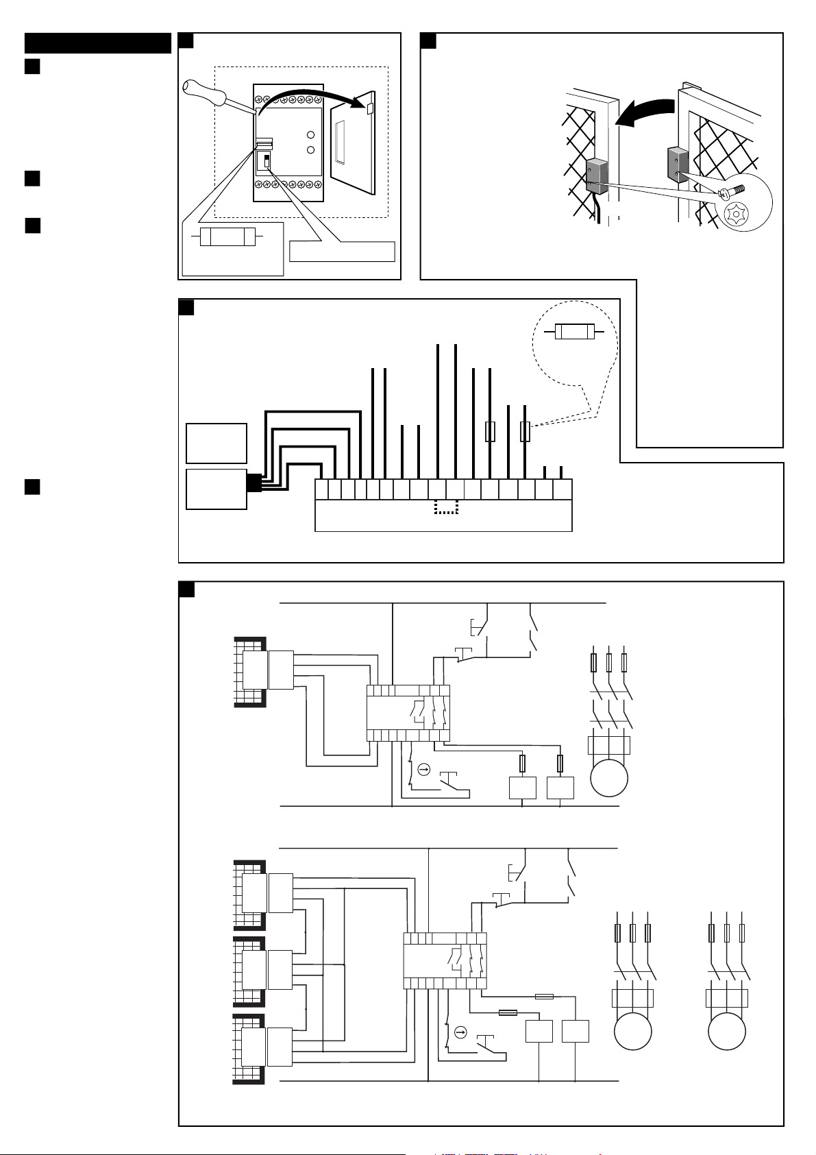
(a) Voltage Selector / Spannungswählschalter /
3
Sélecteur de tension
(b) Mount in enclosure to a min of IP 54.
(a) Mounting / Montage / Montage
4
(b)
It is advisable, where possible, to
mount the switch and actuator on
non-ferrous materials otherwise it
can affect the operating distances.
110
230
Es wird empfohlen, den Schaltsensor
und den Betätiger nach Möglichkeit
auf nicht-ferritischen Materialien zu
montieren, um den Schaltabstand
(c) Actuator
nicht zu beeinflussen.
Nous conseillons, si cela et possible,
de monter le contact et l'émetteur
(d) Sensor
sur un support non ferreux qui
500 mAT
(c) Fuse replacement
(d) 110/230V selector switch
pourrait affecter les distances
d'enclenchement.
(e)
NOTE: Using anaerobic thread locking
compounds can have a detrimental
effect on the plastic switch case if the
(a) Wiring Connection / Anschlüsse / Connexions
5
(j) 110/230V AC SUPPLY
(g)
(e)
(d)
(f)
RED
GREEN
YELLOW
BLUE
(c) SIPHA
ACTUATOR
(b)
SIPHA
SENSOR
(k)
(n)
(i) MANUAL RESET AND/OR
CONTACTOR MONITORING
(l) SAFETY OUTPUT 1
(j)
24V AC/DC
SUPPLY
(CLOSED)
(l) SAFETY OUTPUT 2
IMPORTANT
Fuse externally
Quick Blow Fuse
5A MAX AC
3A MAX DC
(CLOSED)
Fuse
(m)
AUXILIARY (OPEN)
- NOT FOR SAFETY USE
13
32114
A1
A2+---
4
SIPHA CONTROL UNIT
X1
X2
23 24 31 32
(h) Link X1 X2 if
reset is not required
compounds come into contact with the
switch case.
ANMERKUNG: Anaerobe Kleber zur
Sicherung der Schraubgewinde greifen
das Kunststoffgehäuse der Sensoren
an, deshalb Berührung der Gehäuse
mit Klebmittel sorgfältig vermeiden.
NOTE : L'utilisation de colle pour le
blocage des vis de fixation peut avoir
un effet désastreux si le produit rentre
en contact avec le boîtier plastique.
(p)
Shown with guard closed and
machine able to be started.
Dargestellt bei geschlossener
Schutztür und startbereiter Maschine.
Présenté avec porte fermée et
machine prête à démarrer.
(a) Application wiring examples / Beispiele für Anwendungsverkabelungen / Exemples de connexions
6
24VAC/DC
(j)
STOP
MOMENTARY
(e)
BLUE
(f)
(d)
(b)
GUARD
CLOSED
(s)
GUARD
(b)
CLOSED
(b) GUARD
CLOSED
(c)
SIPHA
SENSOR
SIPHA
ACTUATOR
Single sensor and two contactors with manual reset and contactor monitoring. Machine will start when guard is closed,auxiliary contacts at K1 & K2 are closed
(i.e. both contactors are OFF),reset button is pressed and then start button is pressed.
24VAC/DC
(c)
(d)
SIPHA
SENSOR 1
SIPHA
ACTUATOR 1
(d)
(c)
SIPHA
SENSOR 2
SIPHA
ACTUATOR 2
(h)
(e) (e) (h)
(d)
(b) GUARD
CLOSED
Three sensors and two contactors with manual reset and contactor monitoring. Machine will start when all guards are closed, reset button is pressed and then start button is pressed.
(t)
NOTE: The use of multiple sensors connected to a single control unit is only suitable in applications where each guard door is always opened and then
shut individually. Otherwise some single faults may not be detected and unintentional lockout reset may occur if two or more guard doors are open at the same time.
(c)
SIPHA
ACTUATOR 3
SIPHA
SENSOR 3
YELLOW
A11213
SIPHA
(k)
CONTROL
UNIT
A2+---43
(g)
GREEN
(h)
RED
(f)
GREEN
(g)
RED
BLUE
(e)
YELLOW
GREEN
(e)
BLUE
YELLOWYELLOW
(g)
RED
BLUE
(f)
YELLOW
GREEN GREEN
(g)
(g)
RED
(h)
PUSH BUTTON
31
X1
32
X2 142324
K1 (AUX)
(q)
RESET
K2 (AUX)
(f)
(k)
MOMENTARY
PUSH BUTTON
(j)
STOP
MOMENTARY
PUSH BUTTON
31
A11213
SIPHA
CONTROL
UNIT
X1
32
A2+---43
X2 142324
K1 (AUX)
K2 (AUX)
(n)
(q)
START
MOMENTARY
PUSH
BUTTON
FUSE
RESET
MOMENTARY
PUSH BUTTON
(m)
(n)
K1 (AUX)
K2 (AUX)
(r)
FUSES
START
MOMENTARY
PUSH
BUTTON
FUSE
K1
(m)
(o)
L1 L2 L3
K1
K2
K2K1
K1 (AUX)
K2 (AUX)
M
(o)
(p)
CONTACT
PROTECTION
E.G. THERMAL CUT OUT
L1 L2 L3
K1
K2
M
(p)
CONTACT
PROTECTION
E.G. THERMAL CUT OUT
K2
L1 L2 L3
M
M4
100cN.m
Page 3

Deutsch /
Français
7
(a) Vor jedem Öffnen der abgesicherten
Schutztüren ist stets zu überprüfen, ob
die Stromversorgung getrennt, und die
Maschine zum Stillstand gekommen ist.
WICHTIG: Nach erfolgter Installation
und Inbetriebnahmeprüfung sollten die
Montageschrauben des Betätigers und
des Sensoren zur Erkennung
unbefugter Eingriffe mit einer
Farblackmarkierung oder einem
ähnlichen Mittel gesichert werden. /
Chaque fois que la porte contrôlée par
l’interverrouillage est ouverte, vérifiez que
l’alimentation est coupée et que la
machine s’arrête
IMPORTANT : après l’installation et la mise
en service, les vis de fixation de l’émetteur
et du récepteur doivent être enrobées d’un
vernis de blocage ou d’une matière
similaire.
(b) Montage auf 35mm DIN-Schienne /
Montage sur rail DIN 35mm
(c) Steuergerät /
(d) Schaltsensor - Typ 1 /
(e) Betätiger - Typ 1 /
(f) Schaltsensor - Typ 1 /
(g) Betätiger - Typ 1 /
Dispositif de commande
Contact - Type 1
Emetteur - Type 1
Contact - Type 2
Emetteur - Type 2
7
(a) Check the machine is isolated and stopped whenever the interlocked
guard door is open.
IMPORTANT: After installation and commissioning, the actuator and
switch fixing screws should be coated with tamper evident varnish or
similar compound.
6.0
4.8
24
4.2
M4
5.5
48
22 13
25
(d)
SWITCH - TYPE 1 SWITCH - TYPE 2
12
12
24
(e)
48
24
ACTUATOR - TYPE 1
120
45.5
73.0
35MM DIN RAIL MOUNTING
(b)
(c)
CONTROL UNIT
4.2
25
22
13
M4
4.8
7
68
82
7
4.5
19
(f)
4.2
41
41
5
5
4.5
7
7
19
9
41
73
82
41
7
4.5 4.5
19
(g)
ACTUATOR - TYPE 2
7
19
Technical Specifications
(d)
Conforming to standard
Power supply
Power consumption
Safety inputs
Max input resistance
EN954-1 Cat.3 EN60204, IEC 947-5-3
24 V AC/DC or 110/230 V AC Selectable
< 4 V A.
1 Sensor (1 N/O 1N/C)
Red/Blue - 200Ω
Green/Yellow - 150Ω
Max. Switching distance (safety)
Type 1 sensor - make 5mm, break 11mm.
Type 2 sensor - make 9mm, break 12mm.
Min. approach speed
Safety Relay output
Max
switched AC current/voltage
Max
switched DC current/voltage
Min
switched current/voltage
Max output fuse
17mm/sec.
2 N/O TUV approved
4A / 250V AC / 1000VA at COSØ=1.
2 A / 30 VDC / 60 W.
10 mA / 10 V AC/DC
5 A quick acting on AC.
3 A quick acting on DC.
Auxiliary output
Indication
1 N/C (not for safety)
LED 1 - GREEN = output closed.
LED 2 - RED = power on.
Max. drop out time
Impulse withstand voltage
Operating temperature
Contamination level
Humidity
Degree of enclosure protection
25 m Sec.
2500V.
-10°C to +55°C.
lll.
90% RH at +50°C.
Control unit: IP 40 DIN 0470.
Terminal isolation: IP 20 DIN 0470.
Sensor/Actuator: IP 67.
Max. conductor size
1 x 2.5mm
stripped 8mm, 1 x 4mm
Housing
Terminals
16 Way D=120 H=73 W=45.5mm.
Plus-minus terminal screws M3.5.
Box terminal with wire protection.
Weight
Control unit - 590g.
Sensor/actuator - 100g.
Material
Control unit - red polycarbonate
Sensor/actuator - red moulded ABS.
Installation group
Mechanical life
Fixing details
C in accordance with VDE 0110.
1 million
Control unit - 35mm DIN rail.
Sensor - M4
Torque settings - Terminal screws
Fixing bolts
Shock
Vibration
1.0Nm (0.79lbs/in)
1.0Nm
IEC 68-2-27 30gms IIms
IEC 68-2-6 10-55Hz
UL991 Class C 10-150Hz
2
stranded with sleeves
2
solid conductor.
Konformität mit folgenden Normen
Leistungsversorgung
Leistungsaufnahme
Schutzeingänge
Max. Eingangswiderstand
Max. Schutz-Schaltabstand
Min. Näherungsgeschwindigkeit
Schutzrelais-Ausgang
Max. ACSchaltstrom/Schaltspannung
Max. DCSchaltstrom/Schaltspannung
Min. Schaltstrom/Schaltspannung
Max. Ausgangssicherung
Hilfsausgang
Anzeigen
Max. Abfallverzögerung
Bemessungs-Stoßspannung
Betriebstemperaturbereich
Kontaminationsklasse
Feuchtigkeit
Gehäuse-Schutzklasse
Max. Leitergröße
Gehäuse
Anschlußklemmen
Gewicht
Material
Installationsklasse
Mechanische Lebensdauer
Montagedetails
Anzugsdrehmoment-
Klemmenschrauben
Montagebolzen
Stoßbelastung
Vibration
EN954-1 Cat.3 EN60204, IEC 947-5-3
24 V AC/DC +/- 15%.
< 4VA.
1 Arbeitskontakt + 1 Ruhekontakt
Rot/Blau - 200 Ω
Grün/Gelb - 150 Ω
Sensor Typ 1 - Kontakt 5 mm,
Unterbrechung 11 mm
Sensor Typ 2 - Kontakt 9 mm,
Unterbrechung 12 mm
17mm/s
2 Arbeitskontakt, TÜV-Zulassung
4 A/250 V AC / 1000 VA bei
COSØ=1
2 A / 30 V DC / 60 W
10 mA / 10 V AC/DC
5 A Flinksicherung für AC
3 A Flinksicherung für DC
1 Ruhekontakt (nicht für Schutzzwecke)
LED - Grün = Ausgang geschlossen
LED - Rot = Strom EIN
25 ms
2500 V
-10 °C bis +55 °C
III
90% rel. Luftfeuchtigkeit bei +50°C
Steuergerät: IP40
Klemmenisolierung: IP20
Sensor/Betätiger: IP67
2
1 x 2.5 mm
bloßgelegt 8 mm, 1 x 4mm
Einzelleiter mit Muffen
2
Festleiter.
16 Eingänge, T=120, H=73, B=45.5mm
Plus-minus, unverlierbare
Klemmenschrauben M3.5.
Kastenklemme mit Kabelschutz
Steuergerät - 147g
Sensor/Betätiger - 100g
Steuergerät-rotes Polycarbonat
Sensor/Betätiger-rotes Form-ABS
C, nach VDE 0110
1 million
Steuergerät-35mm DIN-Schiene
Sensor - M4
1,0 Nm (0.79 lbs/in)
1,0 Nm
IEC 68-2 27, 30 g IIms
IEC 68-2-6, 10 -55 Hz
UL991 Klasse C, 10 - 150 Hz
Spécifications TechniquesTechnische Daten
Conforme aux normes suivantes
Alimentation
Puissance consommée
Entrées de sécurité
Résistance d’entrée maximum
Distance de commutation
(de sécurité) Max.
Vitesse minimale d’approche
Sortie du relais de sécurité
Courant/tension c.a. commuté maxi
Courant/tension c.c. commuté maxi
Courant/tension c.a. commuté
minimum
Fusible de sortie maximum
Sortie Auxilaire
Indication
Temps d’arrêt maxi :
Tension de régime de l’impulsion
Température de service
Niveau de contamination
Humidité
Degré de protection du boîtier
Dimensions maxi des conducteurs
Boîtier
Bornes
Poids
Matériaux
Groupe d’installation
Durée de vie mécanique
Fixation
Couples de serrage :
Bornes filetées
Boulons de fixation
Chocs
Vibrations
EN954-1 Cat.3 EN60204, IEC 947-5-3
24V c.a./c.c. ±15%
< 4A
1 N/O + 1 N/F
Rouge/Bleu - 200Ω
Vert/jaune - 150Ω
Contact type 1 : conj : 5 mm disj. : 11 mm
Contact type 2 : conj : 9 mm disj. : 12 mm
17mm/sec
2 N/O, homologué TUV
4A/250V c.a. / 1000 VA à COS Ø=1
2A / 30 V c.c. / 60 W
10 mA / 10 C.A./C.C.
5 A à action rapide sur c. alternatif
3 A à action rapide sur c. continu
1 N/F (non pour la sécurité)
Voyant vert : sortie fermée
Voyant rouge : sous tension
25 msec
2500 V
-10ºC à +55ºC
III
90% h.r. à +50ºC
Disp. de commande : IP40
Isolation des bornes : IP20
Contact/Emetteur : IP67
2
1 x 2.5 mm
dénudé jusqu’à 8 mm, 1 fils uniques
de 4 mm
toronnés avec gaine
2
.
16 voies Prof.x h. l. = 120 x 73 x 45,5 mm
Bornes filetées prisonnières M3.5 +/-.
Boîte à bornes avec protection des fils
Disp. de commande : 147 gr.
Contact/Emetteur - 100 gr.
Disp. de commande : polycarbonate, rouge
Contact/Emetteur : moulage ABS, rouge
C conf. à VDE0110
1 million
Disp. de commande : rail DIN de 35 mm
Contact : M4
1,0 Nm (0,79 lb/in)
1,0 Nm
CEI 68-2-27 30gms IIms
CEI 68-2-6 10-55Hz
UL991 Classe C 10-150 Hz
Page 4

(e)
The Sipha 2 control unit checks for single faults (from the sensor to the
control unit output) when the sensor is operated (guard door opened or
closed). The Sipha 2 will also monitor contactor operation. Where interlocked
doors are used infrequently, a weekly operational check of the system should
be carried out as part of the regular inspection program.
If a fault is detected the control unit will go to a lockout state. (Green output
LED OFF, Red power LED ON - with guard open or closed).
(f)
At least every 6 months
Isolate all power! Check actuator to sensor target alignment. Check terminal
connections. Check wiring for signs of damage. Check the unit locks out when
a single fault occurs by placing a link across control unit terminals 1 & 4.
Ensure the interlocked guard door is closed. Reinstate power to the Sipha 2
control unit ONLY, press the reset button (if fitted) and open the guard door.
Check that the unit locks out. Remove the link, disconnect the YELLOW wire
at terminal 2 and repeat the test. If there are multiple sensors connected to
the control unit, repeat these tests for each sensor in turn. During tests check
LED's are operating correctly.
If the system operates correctly during tests, reinstate connections and power.
Before allowing normal machine operation, check that the machine stops
when the guard door is opened.
(g)
The most likely fault resulting in a lockout state is misalignment of the
actuator sensor targets or damage to the wiring between sensor and actuator.
In these cases, to return from the lockout state, rectify the fault and open
then shut the guard door..
If there is any internal malfunction or damage, no attempts should be made to
repair it. The unit should be replaced before machine operation is allowed.
DO NOT DISMANTLE THE UNIT.
BETRIEBSFUNKTIONUSE UTILISATION
Das Steuergerät Sipha 2 überprüft einzelne Fehler (vom Sensor bis zum
Ausgang des Steuergerätes hin) bei Bewegungen des Sensors (d.h. beim
Öffnen oder Schließen der Schutztür). Das Gerät Sipha 2 überwacht ferner
die Funktion der Schütze. Bei einer generell infrequenten Betätigung von
sicherheitsverriegelten Schutztüren sollte eine wöchentliche Funktionsprüfung
des Systems als Teil des regelmäßigen Inspektionsprogramms durchgeführt
werden.
Bei Erfassung eines Fehlers wird das Steuergerät in einen Sperrzustand
versetzt (grüne Ausgangs-LED AUS, rote Strom-LED EIN – bei geöffneter oder
geschlossener Schutztür.
Le dispositif de commande Sipha 2 vérifie la présence de défauts individuels
(du contact à la sortie du dispositif de commande) lorsque le contact est
actionné (ouverture ou fermeture de la porte). Le Sipha 2 assure également
le contrôle des contacteurs. Lorsque des portes interverrouillées sont
rarement utilisées, on doit effectuer un contrôle opérationnel du système dans
le cadre d'un programme d'inspection périodique.
Lorsqu’on relève la présence d’un défaut, le dispositif de commande passe en
mode sécurité (voyant de sortie vert éteint, voyant d’alimentation rouge
allumé - porte ouverte ou fermée).
INSPEKTION UND WARTUNGINSPECTION & MAINTENANCE INSPECTIONS ET ENTRETIEN
Mindestens alle 6 Monate:
Sämtliche Spannungsversorgungen trennen! Die Magnetfläche des Betätigers
auf Fluchtungsfehler mit dem Sensor überprüfen. Alle Klemmenanschlüsse
überprüfen. Alle Kabel auf Anzeichen von Beschädigung überprüfen. Die
Sperrfunktion des Systems bei einem Einzelfehler durch Überbrückung der
Klemmen 1 und 4 des Steuergerätes überprüfen. Dabei darauf achten, daß die
abgesicherte Schutztür geschlossen ist. Die Spannungsversorgung NUR an das
Sipha 2 Steuergerät wiederherstellen, den Rückstellungs-Drucktaster (falls
vorhanden) betätigen, und die Schutztür öffnen. Die Sperrfunktion des Gerätes
überprüfen. Anschließend die Kontaktbrücke entfernen, das GELBE Kabel von
Klemme 2 lösen, und den Test wiederholen. Bei mehreren, am Steuergerät
angeschlossenen Sensoren, diese Tests nacheinander für jeden Einzelsensor
durchführen. Während dieser Tests die korrekte Funktion der LED-Anzeigen
prüfen.
Arbeitet das System während der Tests vorschriftsmäßig, alle Anschlüsse und
die Leistungsversorgung erneut herstellen. Vor Aufnahme der normalen
Betriebsfunktion der Maschine zuerst überprüfen, ob die Maschine nach Öffnen
der Schutztür zum Stillstand kommt.
Au minimum une fois tous les 6 mois
Couper l’alimentation. Vérifier l’alignement contact/émetteur. Vérifier les
connexions des bornes. Vérifier l’endommagement éventuel du câblage.
Vérifier que le dispositif se bloque en présence d’un défaut unique en couplant
les bornes 1 et 4 de dispositif de commande. Vérifier que la porte
interverrouillée est fermée. Remettre sous tension le dispositif de commande
Sipha 2 SEULEMENT, appuyer sur le bouton rouge (le cas échéant) et ouvrir la
porte. Vérifier que l’appareil se verrouille. Enlever le coupleur, détacher le fil
JAUNE à la borne 2 et répéter le même test. Si plusieurs contacts sont reliés
au dispositif de commande, répéter ces tests pour chaque contact à tour de
rôle. Au cours de ces tests, vérifier que la machine s’arrête lors de l’ouverture
de la porte.
En cas de détection d’un défaut, le dispositif de commande passe à l’état
verrouillé (voyant de sortie vert ETEINT, voyant rouge de mise sous tension
ALLUMÉ, porte ouverte ou fermée).
REPARATURREPAIR RÉPARATION
Die häufigsten Ursachen für die Auslösung eines Sperrzustandes sind entweder
Fluchtungsfehler zwischen den Magnetflächen des Sensors und Betätigers, oder
Kabelschäden zwischen Sensor und Betätiger. Zur Aufhebung des
Sperrzustandes in diesen Fällen, den Fehler beseitigen, und anschließend die
Schutztür öffnen und wieder schließen.
Falls Fehlfunktionen oder Schäden auftreten, keine Versuche zur Reparatur
unternehmen. Der Schalter muß ersetzt werden, bevor die Maschine wieder
gestartet wird.
GERÄT DARF NIEMALS GEÖFFNEN WERDEN!
Le mauvais alignement des cibles de l’émetteur et du récepteur ou la
détérioration du câblage sont les principales causes du verrouillage de la
chaîne de sécurité. Lorsque cet événement se produit, pour débloquer cette
situation, corrigez le défaut, ouvrez puis fermez la porte.
En cas de dysfonctionnement ou de dégradation, ne pas attendre pour
réparer. L'interrupteur doit être remplacé immédiatement avant le démarrage
de la machine.
DANS TOUS LES CAS, NE DISLOQUEZ PAS L'APPAREIL.
TROUBLESHOOTING
(h)
FEHLERSUCHE
LED Status
Symptom
Output contacts fail to close
Output contacts fail to close
Power Output
OFF OFF
ON OFF
Cause
Fault on power supply to Sipha 2 control unit.
Fault on input circuit. – Actutor to sensor targets not properly aligned.
If an internal fault to the Sipha 2 is suspected please contact the supplier. Do not dismantle the unit.
LED Status
Symptom
Ausgangskontakte schließen nicht
Ausgangskontakte schließen nicht
Strom Ausgang
AUS AUS
EIN AUS
Ursache
Fehler in der Leistungsversorgung zum Sipha 2 Steuergerät
Fehler im Eingangsschaltkreis - Fluchtungsfehler zwischen Magnetflächen des Sensors und des Betätigers
Bei Verdacht auf einen internen Fehler des Sipha 2, sich bitte an Ihren Händler wenden. Das Gerät darf niemals geöffnet werden!
Diode
Symptôme
Les contacts de sortie ne se
Alim. Sortie
Eteint Eteint
Cause
Panne à l'alimentation du dispositif de commande Sipha 2.
ferment pas
Les contacts de sortie ne se
Panne sur circuits d’entrée - Les émetteurs / récepteurs ne sont pas correctement alignés.Allumé Eteint
ferment pas
Si une panne interne apparaît sur un composant du système SIPHA 2, contactez le fournisseur. NE JAMAIS DISLOQUER L’APPAREIL.
DÉPISTAGE DES DÉFAUTS
Drg No: 32737 / Issue No: 0
R
 Loading...