

Page 1
Single Precharge Contactor Replacement Kit
for LiquiFlo 2.0 AC Frame 3 Drive Assembly
Numbers 179910-903-xxx and 179910-905-xxx
(Replaces Obsolete 100-B400ND3 Contactor)
Instruction Manual D2-8100
ATTENTION: Only qualified electrical personnel familiar with the construction and operation of this
equipment and the hazards involved should install, adjust, operate, or service this equipment. Read and
!
understand this manual and other applicable manuals in their entirety before proceeding. Failure to
observe this precaution could result in severe bodily injury or loss of life.
ATTENTION: Do not install or remove modification kits with power applied to the drive. Disconnect
and lock out incoming power before attempting such installation or removal. Failure to observe this
!
precaution could result in severe bodily injury or loss of life.
ATTENTION: DC Bus capacitors retain hazardous voltages after input power has been disconnected.
After disconnecting input power, wait five (5) minutes for the DC bus capacitors to discharge and then
!
check the voltage with a voltmeter to ensure that the DC bus capacitors are discharged before touching
any internal components. Failure to observe this precaution could result in severe bodily injury or loss of
life.
ATTENTION: The user is responsible for conforming with all applicable local, national, and
international codes. Failure to observe this precaution could result in damage to, or destruction of, the
!
equipment.
ATTENTION: The drive contains ESD- (Electrostatic Discharge) sensitive parts and assemblies. Static
control precautions are required when installing, testing, servicing or repairing the drive. Erratic machine
!
operation and damage to, or destruction of, equipment can result if this procedure is not followed.
Failure to observe this precaution could result in severe bodily injury or loss of life.
What the Kit Contains
Single Precharge Contactor Kit M/N SK-181778-A01 can be used only with LiquiFlo
2.0 AC Frame 3 drives, assembly numbers: 179910-903-xxx and 179910-905-xxx.
Quantity Part Number Description
1 181777-C01 Contactor Bracket
3 181783-C01 Contactor Upper Bus Bar
3 181784-C01 Contactor Lower Bus Bar
2 328858-C34 262 MCM cable, 29.0 inches long
4 328858-C36 262 MCM cable, 35.5 inches long
2 419063-201SM M12 Hex Nut with Conical Washer
NOTE: Contactor 100-D630ED11 to be purchased separately.
Copyright © 2007 Rockwell Automation. All rights reserved.
Page 2

2 Instruction Manual D2-8100
Tools That You Need
What You Need to Do
• 10 mm hex bit socket
• 17 mm socket
• 18 mm socket
• 7/16 inch socket
• 17 mm combination wrench (open / box end)
• Socket ratchet wrench
• 3 inch long socket extension
• 6 inch long socket extension
• Torque wrench (capable of 600 lb.-in. / 50 lb.-ft.)
• Phillips
To install the single precharge contactor kit you need to:
❐ Step 1: Disconnect and lock out input power at the branch circuit.
❐ Step 2: Turn off the drive cabinet circuit breaker.
❐ Step 3: Verify that DC bus capacitors are discharged.
❐ Step 4: Remove the cables, bus bars, stand-offs, and old contactor.
❐ Step 5: Install the new contactor bracket.
®
#2 screwdriver
❐ Step 6: Install the new lower bus bars.
❐ Step 7: Install the new upper bus bars.
❐ Step 8: Reinstall the cabling and precharge resistor wiring.
❐ Step 9: Verify the precharge resistor wiring.
Page 3
Instruction Manual D2-8100 3
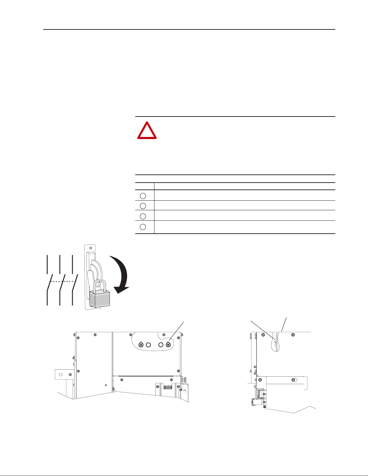
Step 1: Disconnect Power at the Branch Circuit
Step 2: Turn Off Drive Cabinet Circuit Breaker
Step 3: Verify that DC Bus Capacitors are Discharged
Disconnect input power upstream of the drive assembly cabinet. Follow
required safety procedures to lock out circuit during the repair.
Turn off the drive cabinet circuit breaker and open the drive cabinet doors.
ATTENTION: DC Bus capacitors retain hazardous voltages
after input power has been disconnected. After disconnecting
!
input power, wait five (5) minutes for the DC bus capacitors to
discharge and then check the voltage with a voltmeter to ensure
that the DC bus capacitors are discharged before touching any
internal components. Failure to observe this precaution could
result in severe bodily injury or loss of life.
Task Description
Turn off and lock out input power. Wait five minutes.
A
Verify that there is no voltage at the drive’s input power terminals.
B
Remove top cover.
C
Measure the DC bus potential with a voltmeter while standing on a non-conductive surface
D
and wearing insulated gloves (1000V).
L1 L2 L3
I
O
DC
Neg
(-)
DC Bus Measurement Points on
Laminated Bus Assembly
(0.25 x 0.32 in. male Faston).
Accessible by removal of top cover.
DC
Pos
(+)
Top Cover (Removed)
Front View of Inverter
Right Side View of Inverter
Page 4

4 Instruction Manual D2-8100
Step 4: Remove the Cables, Bus Bars, Stand-Offs, and Old Contactor
Task Description
Remove the cables at both ends, and remove the bus bars and stand-offs. Disconnect
A
precharge wiring.
Remove hardware from the bottom of the contactor, disconnect the cables, and leave the
B
cables in place.
Remove the old contactor.
C
A
C
C
B
NOTE: Cabinet panels removed for
clarity – not required for installation.
Removing cabinet top panels may
provide better access.
Page 5

Instruction Manual D2-8100 5
Step 5: Install the New Contactor Bracket
Task Description
Position and align the new contactor bracket onto the drive.
A
Re-use the four (4) M10 x 40 mm long screws and M10 conical washers from the existing
B
contactor mounting to mount the new contactor bracket.
See DETAIL A
(4) M10 x 40 mm Long Screw
(4) M10 Conical Washer From
Existing Contactor Mounting
17 mm
22 N-m (195 lb.-in.)
Torque
B
New Contactor
A
Bracket
P/N 181777-C01
Min. 1/4 inch
Clearance
Resistors and
New Bracket
Between
DETAIL A
Page 6

6 Instruction Manual D2-8100
Step 6: Install the New Lower Bus Bars
(3) Lower Bus Bars
P/N 181784-C01
Task Description
Install the three (3) new lower bus bars using the three (3) M12 x 35 mm long bolts provided
A
with the new contactor. Tighten to the torque specified in the contactor instructions.
Temporarily remove the upper phase barriers. They will be reinstalled later.
B
Insert the upper two (2) M12 socket head cap screws provided with the new contactor
C
through the upper two (2) holes, and loosely fasten them onto the M12 nuts from the kit.
18 mm
See Contactor
Instructions for Torque
A
C
B
Allen-Bradley
100-D630ED11
Contactor
(28.6 Kg / 63 lbs.)
M12 Hex Nut
with Conical Washer
Page 7

Instruction Manual D2-8100 7
Step 7: Install the New Upper Bus Bars
(3) Upper Bus Bars
P/N 181783-C01
18 mm
See Contactor
Instructions for Torque
Task Description
Position the three (3) new upper bus bars as shown, and install them using the three (3)
A
M12 x 35 mm long bolts provided with the new contactor. Tighten to the torque specified in
the contactor instructions.
Reinstall the upper phase barriers.
B
Install the lower two (2) M12 socket head cap screws provided with the new contactor into
C
the lower two (2) holes. Tighten to the torque specified in the contactor instructions.
Tighten the loosely fastened upper two (2) M12 socket head cap screws to the torque
D
specified in the contactor instructions.
A
B
D
M10 Hex Bit
See Contactor
Instructions for Torque
C
M10 Hex Bit
See Contactor
Instructions for Torque
Page 8

8 Instruction Manual D2-8100
Step 8: Reinstall the Cabling and Precharge Resistor Wiring
Task Description
Install the two (2) 29.0 inch long cables per phase from 2A5-7 to 2K4-L1.
A
Install the two (2) 35.5 inch long cables per phase from 2A5-8 to 2K4-L2 and from 2A5-9 to
B
2K4-L3.
Reconnect the precharge resistor wiring.
C
Reuse the existing cables and hardware, and reconnect the cables to the new contactor.
D
Reconnect the contactor coils A1 and A2, and auxiliary 13 and 14.
E
(2) Cables per Phase
P/N 328858-C34
A
(2) Cables per Phase
B
P/N 328858-C36
C
E
B
(2) Cables per Phase
P/N 328858-C36
(3) M10 x 30 mm Long Screws
D
(6) M10 Hex Nuts
17 mm
22 N-m (195 lb.-in.)
Torque
Page 9

Instruction Manual D2-8100 9
Step 9: Verify the Precharge Resistor Wiring
Verify the precharge resistor wiring by measuring across the open precharge
contactor contacts.
From
Contactor
Termi nal
L1 T1 9 - 11 ohms
L2 T2 9 - 11 ohms
L3 T3 9 - 11 ohms
To
Contactor
Ter min al
Correct
Meter
Reading
Page 10

A
A
Notes:
www.rockwellautomation.com
Power, Control and Information Solutions Headquarters
mericas: Rockwell Automation, 1201 South Second Street, Milwaukee, WI 53204-2496 USA, Tel: (1) 414.382.2000, Fax: (1) 414.382.4444
Europe/Middle East/Africa: Rockwell Automation, Vorstlaan/Boulevard du Souverain 36, 1170 Brussels, Belgium, Tel: (32) 2 663 0600, Fax: (32) 2 663 0640
sia Pacific: Rockwell Automation, Level 14, Core F, Cyberport 3, 100 Cyberport Road, Hong Kong, Tel: (852) 2887 4788, Fax: (852) 2508 1846
D2-8100 – June 2007 P/N 181788-P01
Copyright © 2007 Rockwell Automation, Inc. All rights reserved. Printed in USA.
 Loading...