

Page 1

Distributed Power System
SD3100 DC Power Modules
1250A, 1650A, 3000A DC
Instruction Manual
S-3064
Page 2
Throughout this manual, the following notes are used to alert you to safety considerations:
ATTENTION:Identifies information about practices or circumstances that can lead to personal
injury or death, property damage, or economic loss.
!
Important: Identifies information that is critical for successful application and understanding of the product.
ATTENTION:Only qualified personnel familiar with the construction and operation of this
equipment and the hazards involved should install, adjust, operate, or service this equipment.
!
Read and understand this manual and other applicable manuals in their entirety before
proceeding. Failure to observe this precaution could result in severe bodily injury or loss of life.
ATTENTION:Verify that all sources of AC and DC power are deenergized and locked out or tagged
out in accordance with the requirements of ANSI/NFPA 70E, Part II.
ATTENTION:The user must provide an external, hardwired stop circuit outside of the drive
circuitry. This circuit must disable the system in case of improper operation. Uncontrolled machine
operation may result if this procedure is not followed. Failure to observe this precaution could
result in bodily injury.
ATTENTION:The system may contain stored energy devices. To avoid the hazard of electrical
shock, verify that all voltage on capacitros has been discharged before attempting to service,
repair, or remove a drive system or its components. You should only attempt the procedures in
this manual if you are qualified to do so and are familiar with solid-state control equipment and
the safety procedures in publication 70E.
ATTENTION:An incorrectly applied or incorrectly installed drive system can result in component
damage and/or a reduction in product life. Wiring or application errors–such as undersizing the
motor, incorrect or inadequate AC supply, and excessive ambient temperatures–can result in the
malfunction of hte drive equipment.
ATTENTION: The user is responsible for conforming with all applicable local, national, and
international codes. Failure to observe this precaution could result in damage to, or destruction
of, the equipment.
ATTENTION:This drive system contains parts and assemblies that are sensitive to ESD
(electrostatic discharge). Static control precautions are required when installing, testing, or
repairing this assembly. Component damage can result if ESD control procedures are not
followed. If you are not familiar with static control procedures, refer to Rockwell Automation
publication 8000-4.5.2,
on ESD protection.
Guarding Against Electrostatic Damage
, or another adequate handbook
The information in this users manual is subject to change without notice.
AutoMax™ is a trademark of Rockwell Automation
©1998 Rockwell International Corporation
Page 3

Chapter 1 Introduction
1.1 Field Power Module.........................................................................................1-3
1.2 Standard Features...........................................................................................1-3
1.3 Optional Features............................................................................................1-4
1.4 Related Publications........................................................................................ 1-4
1.5 Terms Used in this Manual..............................................................................1-5
Chapter 2 Mechanical/Electrical Description
2.1 Mechanical Overview ......................................................................................2-2
2.1.1 Control Components .............................................................................2-2
2.1.2 Power Components............................................................................... 2-3
2.1.2.1 Incoming Power ...................................................................... 2-3
2.1.2.2 Armature Power Components.................................................2-4
2.1.2.3 Field Power Module Components........................................... 2-7
2.2 Electrical Overview..........................................................................................2-7
2.3 1250A Power Module Description ................................................................... 2-9
2.3.1 1250A Power Module Component Layout........................................... 2-10
2.3.2 1250A Power Module Dimensions...................................................... 2-12
2.4 1650A Power Module Description .................................................................2-13
2.4.1 1650A Power Module Component Layout........................................... 2-14
2.4.2 1650A Power Module Dimensions...................................................... 2-16
2.5 3000A Power Module Description .................................................................2-17
2.5.1 3000A Power Module Component Layout........................................... 2-18
2.5.2 3000A Power Module Dimensions...................................................... 2-20
C
ONTENTS
Chapter 3 Installation Guidelines
3.1 Planning the Installation ..................................................................................3-1
3.2 Physically Installing the Power Module ...........................................................3-2
3.3 Wiring AC Input Power to the Power Module .................................................. 3-2
3.3.1 AC Input Wire Selection ........................................................................ 3-2
3.3.2 Making an Input Entry Hole................................................................... 3-3
3.3.3 Connecting the AC Input Wires to the Busbars..................................... 3-3
3.4 Wiring AC Input to the Field Power Module..................................................... 3-4
3.4.1 Installing the Field Isolation Transf ormer .............................................. 3-4
3.5 Wiring the Motor .............................................................................................. 3-5
3.5.1 Selecting Wires for the Armature and Field Lines.................................3-5
3.5.2 Connecting the Motor to the Power Module..........................................3-5
3.6 Installing Feedback Devices................................... ...... ....... ...... ....... ...... ....... .. 3-6
3.7 Meter Port Connections...................................................................................3-7
3.8 Grounding the Drive ........................................................................................3-7
3.9 For Information on Initial Start-Up of the Drive................................................ 3-8
Table of Contents
I
Page 4

Chapter 4 Maintenance and Troubleshooting
4.1 Recommended Test Equipment.......................................................................4-1
4.2 System Diagnostics..........................................................................................4-2
4.2.1 Power Module Faults.............................................................................4-2
4.2.1.1 Shorted SCR Fault (Bit 0)........................................................4-2
4.2.1.2 AC Line Synchronization Fault (Bit 3)......................................4-2
4.2.1.3 Instantaneous Overcurrent Fault (Bit 4) ..................................4-3
4.2.1.4 Conduction Timeout Fault (Bit 5).............................................4-3
4.2.1.5 Loss of Field Fault (Bit 6).........................................................4-3
4.2.2 Power Module Warnings........................................................................4-3
4.2.2.1 Three-phase Bridge SCR Not Firing Warning (Bit 0)...............4-3
4.2.2.2 Low Line Voltage/Phase Missing Warning (Bit 1)....................4-3
4.2.2.3 Synchronization Loss Fault Avoided Warning (Bit 3) ..............4-4
4.2.2.4 Current Reference Limit Warning (Bit 4) .................................4-4
4.2.2.5 Identification Test Error Warning (Bit 5) ..................................4-4
4.2.2.6 Field Power Module Overcurrent Warning (Bit 6)....................4-4
4.2.2.7 Fan Loss Warning (Bit 12).......................... .............................4-4
4.3 Component Replacement ................................................................................4-4
4.3.1 Spare Parts Kits.....................................................................................4-4
4.3.2 PMI Regulator........................................................................................4-5
4.3.3 Parallel Gate Amplifier...........................................................................4-5
4.3.4 Field Power Module...............................................................................4-5
4.3.4.1 Replacing Internal Field Power Module AC Input Fuses.........4-5
4.3.4.2 Replacing Field Power Module Components ..........................4-6
Appendix A Technical Specifications........................................................................................... A-1
Appendix B Schematics............................................................................................................... B-1
Appendix C Replacement Parts ....... ...... ....... ...... ....... ...... ...... ....... ....................................... ...... .. C-1
Index ..................................... ...... ....... ...... ....... ...... ....................................... ...... ....... ..Index-1
II
SD3100 Power Modules
Page 5

List of Figures
Figure 1.1 – SD3100 Catalog Numbering Scheme .................................................. 1-1
Figure 2.1 – SD3100 Power Module System Components ......................................2-1
Figure 2.2 – Regulator Assembly .............................................................................2-2
Figure 2.3 – Armature Bridge (Non-Regenerative)................................................... 2-5
Figure 2.4 – Armature Bridge (Regenerative)...........................................................2-6
Figure 2.5 – 1250A Power Module Component Layout..........................................2-10
Figure 2.6 – 1250A Power Module Dimensions .....................................................2-12
Figure 2.7 – 1650A Power Module Component Layout..........................................2-14
Figure 2.8 – 1650A Power Module Dimensions .....................................................2-16
Figure 2.9 – 3000A Power Module Component Layout..........................................2-18
Figure 2.10 – 3000A Power Module Dimensions ................................................... 2-20
Figure 3.1 – Area Available for Conduit Entry (Top View of Leftmost Bay).............. 3-3
Figure 3.2 – Field Terminal Wiring............................................................................3-4
Figure 3.3 – Drive I/O Connections (TB4) ................................................................ 3-6
Figure 3.4 – Resolver and Analog Input Connections (TB5) .................................... 3-6
Figure 3.5 – Meter Port Connections (TB6)..............................................................3-7
Figure 3.6 – SD3100 Grounding...............................................................................3-8
Figure A.1 – Altitude Derating Chart.........................................................................A-1
Figure A.2 – Power Dissipation vs. Armature Current (1250A Power Module) ........A-3
Figure A.3 – Recommended Circuit Breaker Settings (1250A Power Module) ........A-3
Figure A.4 – AC Input Busbars (1250A Power Module)...........................................A-4
Figure A.5 – Power Dissipation vs. Armature Current (1650A Power Module) ........A-6
Figure A.6 – Recommended Circuit Breaker Settings (1650A Power Module) ........A-6
Figure A.7 – AC Input Busbars (1650A Power Module)...........................................A-7
Figure A.8 – Power Dissipation vs. Armature Current (3000A Power Module .........A-9
Figure A.9 – Recommended Circuit Breaker Settings (3000A Power Module) ........A-9
Figure A.10 – AC Input Busbars (3000A Power Module) .......................................A-10
Figure A.11 – Air Baffle Layout (1250A and 1650A Power Modules).....................A-11
Figure A.12 – Air Baffle Layout (3000A Power Module).........................................A-12
Figure B.1 – DC Blower Motor Connections.............................................................B-1
Figure B.2 – 1250A and 1650A Power Modules (Non-Regenerative), Sheet 1........B-2
Figure B.3 – 1250A and 1650A Power Modules (Non-Regenerative), Sheet 2........B-3
Figure B.4 – 1250A and 1650A Power Modules (Regenerative), Sheet 1 ...............B-4
Figure B.5 – 1250A and 1650A Power Modules (Regenerative), Sheet 2 ..............B-5
Figure B.6 – 3000A Power Module (Regenerative), Sheet 1....................................B-6
Figure B.7 – 3000A Power Module (Regenerative), Sheet 2....................................B-7
Table of Contents
III
Page 6

IV
SD3100 Power Modules
Page 7

List of Tables
Table 1.1 – SD3100 Drive Options........................................................................... 1-2
Table 1.2 – Field Power Module Part Numbers........................................................1-3
Table 1.3 – Distributed Power System DC Drives Documentation........................... 1-4
Table 1.4 – Related Motor Control Center Documentation.......................................1-5
Table 2.1 – 1250A Configurations............................................................................ 2-9
Table 2.2 – 1250A Power Module Symbol-to-Component Reference....................2-11
Table 2.3 – 1650A Configurations.......................................................................... 2-13
Table 2.4 – 1650A Power Module Symbol-to-Component Reference....................2-15
Table 2.5 – 3000A Configurations.......................................................................... 2-17
Table 2.6 – 3000A Power Module Symbol-to-Component Reference....................2-19
Table 3.1 – Recommended AC Input Wiring ............................................................3-2
Table 3.2 – Isolation Transformer Wiring Requirements ..........................................3-4
Table 3.3 – Armature Wire Selection........................................................................3-5
Table 3.4 – Field Wire Selection...............................................................................3-5
Table 4.1 – Field Power Module Input Fuses ........................................................... 4-5
Table A.1 – Electrical Specifications (1250A Power Module)...................................A-2
Table A.2 – Electrical Specifications (1650A Power Module)...................................A-5
Table A.3 – Electrical Specifications (3000A Power Module)...................................A-8
Table of Contents
V
Page 8

VI
SD3100 Power Modules
Page 9
C
HAPTER
1
Introduction
SD3100 DC Power Modules convert fixed voltage and frequency three-phase AC
power to adjustable voltage DC power, which can be used to supply the armature or
field of a DC motor. An SD3100 Power Module operates within the AutoMax
Distributed Power System (DPS) environment, and is controlled by the AutoMax
Programming Executive software. The Power Module communicates with the AutoMax
system via an internally mounted Power Module Interface (PMI) rack, which contains
the drive’s control circuits and executes the motor control algorithm.
The SD3100 configuration provides control of DC motors, rated 700 to 2500 HP, with
current ratings of 1250, 1650, and 3000A. Input voltages of 460, 575, and 660 VAC
are available. Figure 1.1 shows the SD3100 catalog numbering scheme.
Distributed Power
System Drive Numb er
SD3100
B = 460 VAC
C = 575 VAC
F = 660 V AC
64 = 700 HP
65 = 750 HP
66 = 800 HP
67 = 900 HP
N = Non-regenerative, 6-pulse
R = Regenerative, 6-pulse
AA = NEMA Type 1 w ithout gaskets and door fan filters
AJ = NEMA Type 1 with g askets and door fan filters
Refer to table 1.1, SD3100 Drive Options.
68 = 1000 HP
69 = 1250 HP
70 = 1500 HP
71 = 1750 HP
AC Input
Voltage
72 = 2000 HP
73 = 2250 HP
74 = 2500 HP
3
B
1
HP
64
Unit
Configuration
N
2
Enclosure Options
AA
4
1. A separately-ordered, separately-mounted 7.5 to 25kVA field isolation transformer is required. See section 1.1.
2. Units accommodate top ent ry and bottom exit. An additional sec ti on is required f or bottom entry.
A separate additional section is required for top exit.
3. Non-regenerative units not offered for 3000A modules.
4. Add option codes here. Separate option codes with dashes.
Figure 1.1 – SD3100 Catalog Numbering Scheme
Introduction
1-1
Page 10

Table 1.1 – SD3100 Drive Options
Drive Option Code Description
6P Standard capacity control transformer with primary fusing
Control Po w er Sourc e
1
6TB
6SC 115 VAC control power supplied by others
2
Dynamic Braking Cont act or
Unit Door Nameplate
1
14DB Dynamic braking contactor option
M3EW White background with black lettering; phenolic label
14WLBL
Miscellaneous
J12
J11 Audio phone jack
Auxiliary Contact s 989X
14BN (1) NEMA 1 FVNR starter assembly internally mounted with 30A fuse blocks
14B2N (2) NEMA 1 FVNR starter assemblies internally mounted with 30A fuse
Blower Starters
5, 6
14B2NX (2) NEMA 2 FVNR starter assemblies internally mounted with 60A fuse
14BI (1) IEC 24A starter assembly internally mounted with 30A fuse blocks
14B2I (2) IEC 24A starter assemblies internally mounted with 30A fuse blocks
14B2IX (2) IEC 30A starter assemblies internally mounted with 60A fuse blocks
14LSP
Protection
14AFL Air flow loss swit ches
Field Su pply Upgra de
Incoming Protecti on
8, 9
1
14FX Field supply upgrade for fields requiring 15 to 60A
CM Circuit breaker
LF Line fuses
HB1600 1600A AC power bus for 1250A units with 460 or575 VAC inputs
5
Horizontal Power Bus
HB2000 2000A AC power bus for 1250 and 1650A units with 460 or 575 VAC inputs
HB3000 3000A AC power bus for 1250 and 1650A units with 460 or 575 VAC inputs
Horizontal Control Bus CB90
Input Option 14HBC
1. User must select one option from this group.
2. This option includes a dynamic braking contactor mounted in a separate 20” MCC section.
3. Cloth wire labels are standard. Datab labels provide a clear plastic cover on top of the labels for added protection.
4. User must supply 115 VAC control power and wiring to the duplex receptacle.
5. User may select one option from this group.
6. Fuses and overload elements are user-supplied and must be power-matched to the installation.
7. Line RC suppressor is required for installations where the primary of the distribution transformer is 2300 VAC or greater.
8. Standard Field Power Module is rated to supply field currents up to 15A. The upgrade provides a Field Power Module rated up to 60A.
(Nominal field currents based on 85% efficiency, unit control power usage, and a 300V field supply.)
9. A separately-ordered, separately-mounted 7.5kVA to 25kVA field isolation transformer is required. See the following section.
115 VAC control power, factory wired from 115 VAC control bus to drive unit
(1250 and 1650A units only). Requires option CB90
Brady Datab™ wire labels
15 VDC, 15A duplex receptacle, user-wired
(2) normally open and (2) normally close d contactors mounted in ternally in
•
3
4
1250/1650A unit, or
(4) normally open and (4) normally close d contactors mounted in ternally in
•
3000A unit
blocks
blocks
Line RC suppressor module
7
90A AC control bus for 1250 and 1650A units that have a horizontal power
bus option
AC pow er input is wired from the horizo ntal thru-bu s to the circuit br eake r/line
fuses for 1250 and 1650A units that have a horizontal power bus option
1-2
SD3100 Power Modules
Page 11

1.1 Field Power Module
The single-phase Field Power Module is integrally mounted within the SD3100 Power
Module to provide the motor field excitation. The Field Po wer Module is rated 15 or 60
amps at 230/460 VAC . The 15A unit is supplied as standard. The 60A unit is available
as an option.
The Field Power Module requires a separately-ordered, separately-mounted field
isolation transformer. The Field Power Module’s AC input lines are connected through
the isolation transformer to the L1 and L3 inputs of the SD3100. The 15A module
requires a step-down transformer rated up to 7.5kVA (application dependent). The
60A module requires a step-down transformer rated 7.5kVA to 25kVA (application
dependent). All systems operate on three-phase 50/60 Hz., 460 to 660 VAC.
The Field Power Module is available in the configurations listed in table 1.2.
Table 1.2 – Field Power Module Part Numbers
Part No. Amps AC Input Description Mounting
805405-3R
805405-5R
1. For application information see instruction manual S-3060.
1
1
15 230 / 460 VAC Reversing (S2R) Integral
60 230 / 460 VAC Reversing (S2R) Integral
1.2 Standard Features
SD3100 DC Power Modules have the following features:
•
Three-phase 460, 575, or 690 VAC input
•
1250, 1650, and 3000 amp units
•
S6 (non-regenerating) and S6R (regenerating) configurations
•
15 amp Field Power Module
•
DC output contactor
•
PE / TE bus
•
Choice of incoming circuit breaker or input line fuse protection
•
Electronic motor overload protection
•
SCR power semiconductors / dv/dt protection
•
SCR leg fuses
•
Cell chokes
•
Protection against unequal current sharing among SCRs
•
Protection from AC line dips and transients
•
Top AC entry / Bottom DC exit
Introduction
•
Power through-bus (1250A and 1650A Power Modules)
1-3
Page 12

•
115VAC control bus (90A)
•
Fiber-optic communication with the Distributed Power System Universal Drive
Controller (UDC) module
•
Drive nameplate - white/black letters
1.3 Optional Features
The following features are available as options:
•
60 amp Field Power Module
•
NEMA blower starter
•
IEC blower starter
•
Air flow switch
•
Line suppressor
•
115 VAC convenience outlet
•
Phone jack
1.4 Related Publications
The instruction manuals in binder S-3000 describe the other system hardware, system
software, and communications, as listed in table 1.3. It is assumed that the user is
familiar with these manuals before installing, operating, or performing maintenance
upon SD3100 DC Power Modules. Further information pertaining to SD3100 Power
Modules can be found in instruction manuals S-3045 and S-3060, as listed in the
table.
Table 1.3 – Distributed Power System DC Drives Documentation
Publication Number Description
S-3000 Distributed Power System DC Drives Binder
S-3005 AutoMax Distributed Power System Overview
S-3006 SD3000 Drive Configuration and Programming
S-3007 Universal Drive Controller Module
S-3008 Power Module Interface Rack and Modules
S-3009 Fiber Optic Cabling
S-3011 Diagnostics, Troubleshooting and Start-up Guidelines
Related DPS Documentation
S-3045 DPS Parallel Gate Amplifier System
S-3060 DPS Single-Phase Field Power Modules
1-4
SD3100 Power Modules
Page 13

Installation of the motor control center (MCC) is described in the manuals listed in
table 1.4.
Table 1.4 – Related Motor Control Center Documentation
Publication Number Description
2100-5.5 Instructions - Receiving, Handling, And Storing Motor
Control Centers
2300-5.1 Bulletin 2300 Family of Drive Systems Hardware
Additional information about using SD3100 Power Modules as part of a Distributed
Power System is found in the wiring diagrams, prints, and other documentation
shipped with each drive system. Always consult the prints shipped with the drive for
specific mounting and connecting information about your system.
1.5 Terms Used in this Manual
The terms listed in this section have the specific meanings given below when they
appear in this manual.
Application
software is being used.
Armature Power Module
power bridge and related hardware components used to control the armature current.
Diagnostic
error conditions.
Drive
Power Module as a means or apparatus for transmitting motion to a machine or
machine part.
Drive warning
for by the PMI operating system. Drive warnings are reported in register 203/1203 in
the UDC. A drive warning will not shut down the drive. System response is determined
by the application task.
Error
Drive fault
that will shut down the drive. Drive faults are reported in register 202/1202 in the UDC.
Field Power Module
Field Power Module is integrally mounted within the SD3100 Power Module.
- The process for which the combination of hardware and control
- the power structure containing the three-phase SCR
- a software routine or hardware circuit specifically designed to check for
- the combination of a UDC, a PMI, a Field Power Module, and an Armature
- a potentially hazardous or undesirable operating condition checked
- any operating condition other than the desired one.
- an error, specifically checked for by the PMI Processor operating system,
- a single-phase power unit, used to supply the motor field. The
Introduction
Non-regenerative drive
(S6 configuration).
Regenerative drive
or reverse (S6R configuration).
- a drive capable of motoring operation only
- a drive capable of motoring or regenerating operation, forward
1-5
Page 14

1-6
SD3100 Power Modules
Page 15
LINE FUSES OR CIRCUIT BREAKER
L1
L2
C
HAPTER
2
Mechanical/Electrical Description
Rockwell Automation SD3100 DC Power Modules are built using a Distributed Power
System PMI regulator and a high-horsepower silicon-controlled rectifier (SCR) bridge.
All components are housed in a NEMA 1 metal enclosure.
This chapter provides general information on the mechanical and electrical
characteristics of SD3100 Power Modules, followed by specific information on the
1250A, 1650A, and 3000A units.
FU-A
CURRENT
XFMRS
FU-B
EXTERNAL
FIELD ISO
XFMR
L3
PMI RACK
RESISTOR
SCALING
MODULE
ARMATURE
FEEDBACK
FWD GATE SIGNALS
REV GATE SIGNALS
TO FIEL D
POWER MODULE
DELTA/WYE
PHASING
XFMR
FROM DC
ARMATURE
SCALING UNI T
115 VAC
PGA RACK
DRIVE I/O
Figure 2.1 – SD3100 Power Module System Components
FWD GATE
SIGNALS
REV GATE
SIGNALS
RESOLVER FEEDBACK
GATE COUPLING CIRCUITS
ARMATURE PO WER
STRUCTURE (S6R)
FIELD
POWER
MODULE
L1
L2
L3
TO P4/
DCPT
+
DC
MOTOR
–
RESOLVER
TO RESISTOR
SCALING UNIT
Mechanical/Electrical Description
2-1
Page 16
2.1 Mechanical Overview
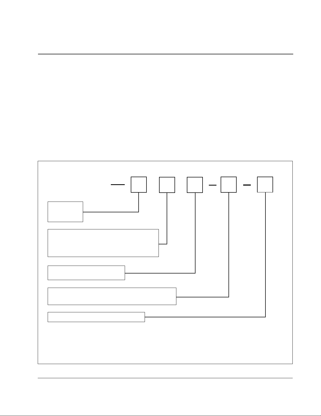
The SD3100 Power Module is composed of the basic components shown in figure 2.1.
These components consist of:
Contr ol components
•
System and control for the Power Module, and
Power components
•
2.1.1 Control Components
The control components are contained in the regulator assembly, along with the Field
Power Module. The regulator assembly is mounted in the lower compartment of the
Power Module’s Disconnect Bay.
FU-A
FIELD
ISOLATION
XFRM
FUSES
that provide the interface to the AutoMax Distributed Power
that convert AC line power to DC power for the motor.
FU-B
SCALING
UNIT
TB1
PMI
RACK
FIELD
POWER
MODULE
PGA
RACK
FWD
REV
TO GATE
COUPLERS
TB2
TB3 TB4
Figure 2.2 – Regulator Assembly
TB5
TB6
The PMI rack contains the four modules that make up the PMI Regulator: the PMI’s
Power Supply, Processor module, Resolver and Drive I/O module, and DC Power
Technology module. The PMI Processor executes the control algorithm and
communicates with the AutoMax processor via its fiber-optic ports. The Resolver and
Drive I/O module provides the interface for speed feedback and control signals. The
DC Pow er Technology module provides the armature feedback, armature forward gate
control, armature reverse gate control (regenerative models only), and the field
feedback and gate control signals for the Field Power Module.
2-2
SD3100 Power Modules
Page 17

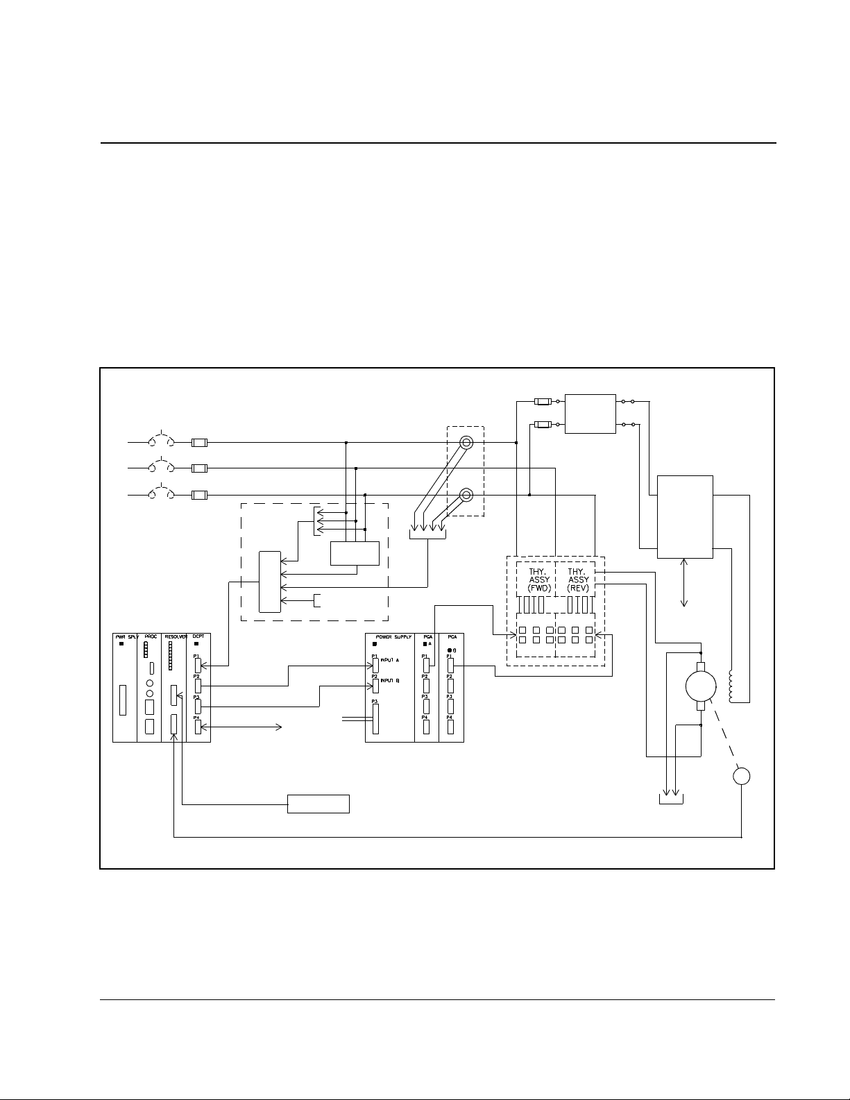
Below the PMI rack is a DPS Parallel Gate Amplifier (PGA), which provides isolation
and amplification of the forward and reverse gate drive signals. The Field Power
Module is mounted to the left of the PMI and PGA racks. At the top of the assembly
are the field isolation transformer fuses and a scaling unit that conditions the armature
feedback signals received via terminal block TB1. T erminal blocks at the bottom of the
assembly provide connection for the field gate and feedback signals (TB2), control
power (TB3), drive I/O (TB4), the resolver (TB5), and the meter ports (TB6). The
forward and reverse armature gate coupler circuits connect to the control circuitry at
the lower right of the compartment.
The Power Module is shipped with the PMI Regulator and all related control
components installed. The PMI is described in detail in the Power Module Interface
Rack and Modules instruction manual (S-3008). Please refer to this manual for further
information. Additional information on the PGA can be found in instruction manual
S-3045.
2.1.2 Power Components
Power components manage and handle the power of the drive under the direction of
the PMI regulator. The power components consist of:
•
the incoming power components
•
the armature power bridge components
•
the Field Power Module
2.1.2.1 Incoming Power
The incoming power components handle the input power and provide it to the Field
Power Module and armature power bridge assemblies.
The following components are used to provide incoming power:
•
circuit breaker or input line fuses
•
user-supplied input line reactor or isolation transformer
•
control power and Field Power Module tap
•
user-supplied field isolation transformer
•
AC line RC suppressor
Circuit Breaker
Power Modules are provided with circuit breakers to protect the input power wiring.
Recommended circuit breaker settings are shown in Appendix A.
Input Line Reactor or Isolation Transformer
The SD3100 system requires a user-supplied line reactor or isolation transformer to
reduce peak currents and harmonics in the incoming power lines. This device is
needed to provide isolation to other equipment on the power lines during regeneration.
Important:
Mechanical/Electrical Description
Failure to use an input isolation device may result in damage to the Power
Module during regeneration.
2-3
Page 18

Control Power and Field Power Module Tap
The first (L1) and third (L3) phase of the incoming power are tapped off and fused to
provide single-phase AC power to the primary of the control power transformer and
the Field Power Module.
Field Isolation Transformer
A user-supplied field isolation transformer must be installed on the AC input of the
Field Power Module as described in section 3.4.1 of this manual. Using a field
isolation transformer provides the following advantages:
•
Provides power matching to the Field Power Module.
•
Permits the Field Power Module to continue operating in the event of a ground fault
in the field windings of the motor.
•
Provides a known minimum AC input impedance for the snubbers to operate
against.
•
Protects other circuits sharing the same power source from line notching
interference caused by the Field Power Module.
•
Provides source impedance to guarantee SCR protection in the event of a short
circuit.
AC Line RC Suppressor
The optional AC line RC suppressor is a device used for limiting line voltage spikes
when the medium voltage source to the primary of the distribution transformer is
switched. This option is required for a primary voltage of 2300V or greater.
Output Inductor
Note that some systems may require an output inductor in series with the armature,
especially for some DC motors that do not have enough internal inductance for a
proper armature commutation process.
2.1.2.2 Armature Power Components
The armature power components convert the 3-phase AC input to a DC output used
for powering the motor armature.
The following components make up the armature power circuitry:
•
armature SCR bridge (and its subordinate components)
•
leg fuses
•
gate coupler cards (GCCs)
•
DC contactor
2-4
SD3100 Power Modules
Page 19
The non-regenerative bridge is shown in figure 2.3. Cell fuses protect the thyristors in
the event of a bridge failure.
Main
Contactor
3-Phase
AC
Input
SNUBBER
SNUBBER
*&&
*&&
SNUBBER
SNUBBER
*&&
*&&
Figure 2.3 – Armature Bridge (Non-Regenerative)
SNUBBER
SNUBBER
*&&
*&&
A1
Armature
Voltage
A2
Mechanical/Electrical Description
2-5
Page 20
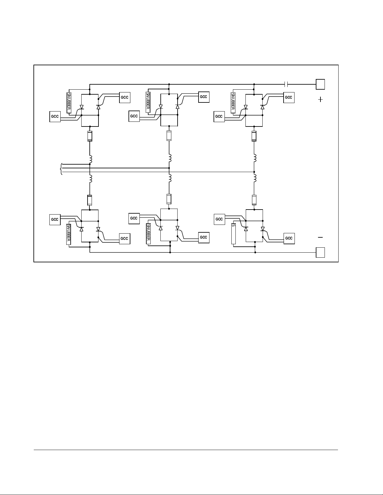
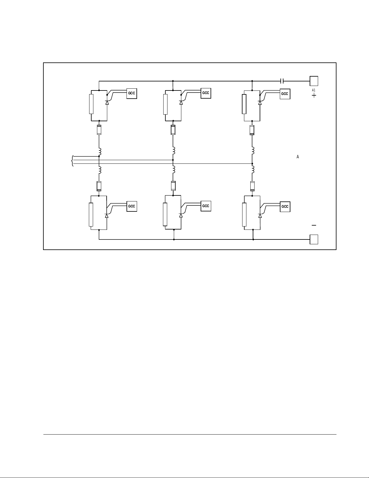
The regenerative bridge, shown in figure 2.4, allows the bridge to direct regenerated
power back onto the incoming lines.
Main
Contactor
*&&
3-Phase
AC
Input
*&&
SNUBBER
SNUBBER
*&&
*&&
SNUBBER
*&&
*&&
SNUBBER
Figure 2.4 – Armature Bridge (Regenerative)
*&&
*&&
*&&
*&&
SNUBBER
SNUBBER
*&&
*&&
A1
Armature
Voltage
A2
2-6
Armature Bridge Components
The armature bridge consists of the following components:
•
Silicon-Controlled Rectifiers (SCRs)
Each Power Module uses silicon-controlled rectifiers (SCRs) in the armature bridge
to switch the incoming 3-phase AC power to DC output power.
These SCRs allow current to flow from anode to cathode when two conditions are
met. First, like a diode, the SCR must be forward biased. Second, an appropriate
pulse must be applied to the gate (through the pulse transformer board).
The current will continue through the SCR until the voltage across it reverses and
the current drops to zero (line commutation).
•
Snubbers
Snubbers (resistor/capacitor assemblies) are installed in parallel with the SCRs to
protect the SCRs from rapid voltage changes (inductive kick) when the SCRs switch
off by suppressing and dissipating the excess voltage.
SD3100 Power Modules
Page 21
•
Gate Coupler Cards
Gate coupler cards amplify the gate signal pulses from the DC Power Technology
module to trigger the SCRs. In addition, these cards provide gate driver isolation
from the control circuits in the PMI rack.
•
Main DC Contactor
The main DC contactor is used to isolate the DC motor armature and to interrupt
the DC current to the motor armature. Coil voltage to the contactor is controlled by
contacts from the pilot relay.
2.1.2.3 Field Power Module Components
The Field Power Module operates on single-phase AC, which must be taken from the
three-phase armature power bridge’s L1 and L3 input lines. The incoming AC must be
supplied to the Field Power Module through an isolation transformer.
The Field Power Module rectifier consists of 8 SCRs in two full-wave bridges,
connected in anti-parallel. Snubber protection is provided to permit operation on a
common bus with other Power Modules. A Hall effect device is used to monitor the DC
output current.
$ ILHOG FO DPS DVVHPEO\ LV SURYLGHG WR PRQLWRU WKH YROWD JH EHWZHHQ WKH )LHOG 3RZHU
0RGXOH©V RXWSXW WHUPLQDOV DQG ,I DQ RYHUY RO WDJH RFFXUV WKH ILHOG FODPS
ILUHV D FURZEDU 6&5 WKDW VDIHO\ GL VVLSDWH V WKH HQHUJ\ LQ WKH ILHOG
2.2 Electrical Overview
SD3100 DC Power Modules convert fixed voltage and frequency three-phase AC
power to adjustable voltage DC power for motor armatures, fields, or other
applications that require controlled DC power. Power Module operation is
programmed and controlled in the UDC module in the AutoMax rack and the PMI
Processor in the drive’s internal PMI rack.
Incoming power is supplied from a three-phase AC line. A phasing transformer
provides AC line sequencing and zero-crossing information for each input phase to
determine when SCRs should be fired. The Power Module is capable of auto-phasing
under software control and can adapt to ABC or ACB phase rotation.
The non-regenerative Power Module rectifier consists of 6 SCRs, configured in a
full-wave power bridge. The regenerative Power Module rectifier consists of 12 SCRs
in two full-wave bridges, connected in anti-parallel. Snubber circuits provide dv/dt
protection for the SCRs in each bridge leg.
The firing angle for each SCR is determined by the current regulation algorithm
executing in the PMI Processor. SCR gating signals are provided by the DC Power
Technology module, under the control of the PMI Processor. The gating signals and
firing angles are synchronized with the AC line. The PMI Processor regulates the
current for the application by varying the point in the AC line cycle at which forward
SCR conduction begins. The PMI Processor receives the current reference from the
UDC module in the AutoMax rack. The UDC runs the application task that provides
overall control of the Power Module.
The three-phase SCR power bridge in a non-regenerative Power Module controls
forward rotation (motoring) only. Torque is in the same direction as rotation.
Mechanical/Electrical Description
2-7
Page 22

The two anti-parallel SCR power bridges in a regenerative Power Module control the
direction of motor rotation and the direction of torque, in both forward (motoring) and
reverse (regenerating) directions. The regenerative Power Module allows for
regeneration of power into the AC line under the condition of an overhauling load.
Field Power Module
Operation of the Field Power Module is programmed and controlled in the UDC
module in the AutoMax rack and the PMI Processor in the PMI rack. The firing angle
for each SCR is determined by the field current regulation algorithm executing in the
PMI Processor. The field SCR gating signals are provided by the DC Power
Technology module, under the control of the PMI Processor.
The firing angle for each SCR is synchronized with the AC line feeding it. The PMI
Processor regulates the amount of motor field current by varying the point in the AC
line cycle at which forward conduction begins. The PMI Processor receives the field
current reference from the UDC module in the AutoMax rack. The UDC runs the
application task that provides overall control of the application.
For a full description of the Field Power Module, please refer to instruction manual
S-3060.
2-8
SD3100 Power Modules
Page 23

2.3 1250A Power Module Description
Table 2.1 – 1250A Configurations
Input Voltage (VAC) Output HP
460 700-750
575 750-900
660 700-1000
The 1250A Power Module is supplied in the configurations shown in table 2.1. The
1250A Power Module has the following features:
•
The 1250A Power Module uses twelve SCRs (regenerative) or six SCRs
(non-regenerative) in the armature bridge to convert the 3-phase AC input to a DC
output. The SCRs are built into a heatsink assembly that is cooled by the bridge fan.
•
The 1250A Power Module is protected from incoming fault currents by a circuit
breaker or input line fuses. The components of the Power Module (the armature
bridge, field bridge, and control components) are protected by fuses, MOVs,
snubbers, and/or chokes.
•
The 1250A Power Module is constructed and housed in three bays. The first bay
contains the AC input and control hardware, the second bay contains the armature
bridge hardware, and the third bay contains the DC output hardware.
•
The 1250A Power Module can be built to allow alternative input entry, using either
an optional bottom-entry bay (on the left of the disconnect bay) or an optional
top-hat extension over the AC input bay.
•
The 1250A Power Module can be built with an optional through bus assembly,
allowing the 1250A Power Module and other connected Power Modules to tap off
power from the same AC input.
Figures 2.5 and 2.6 show component locations and Power Module dimensions.
Please refer to these figures when installing or servicing the Power Module. Refer to
Appendix B for wiring diagrams of both the regenerative and non-regenerative
versions of the Power Module.
Mechanical/Electrical Description
2-9
Page 24

2.3.1 1250A Power Module Component Layout
PP1 PP2 PP3
F51*
ACT1 ACT3
L1 L2 L3
SP1
SP2
SP3
SP4
*
F31,
F32,
F33
FU-B
FU-A
F14 F 15
F16
F14 F15
CB11*
or
F52*
EA4
SCALING
UNIT
MP
R1
A2(-)
M1
F17,
F18,
F19
M11
*
F27,
*
F28,
F29
M12
A1(+)
*
*
A14R
F53*
F1,
*
F2,
F3
TB1
PMI
RACK
TB1FAN
A11F
F12
F12A
F9 F9A
A14F
A11R
PP4 PP5 PP6
A16R
A13F
F11 F11A F10
F8
F8A
A16F
A13R
F7
A12R
A12F
A15F
F10A
F7A
A15R
D1
2-10
FIELD
SUPPLY
TB2
TB3
TB4
PT2
TB5
PGA
RACK
TB6
FWD REV
'LVFRQQHFW %D\ %ULGJH %D\ &RQWDFWRU %D\
Figure 2.5 – 1250A Power Module Component Layout
SD3100 Power Modules
Page 25

Table 2.2 – 1250A Power Module Symbol-to-Component Reference
Symbol Description Option 460 VAC 575 VAC 660 VAC
A1(+), A2(-) Armature outputs
A11F - A16F Armature pulse transformer PCB
A11R - A16R Armature pulse transformer PCB
ACT1, ACT3 Line current transformers 2000:1
CB11 Circuit breaker ∗ 1200A, N-frame
F51 - F53
AC line fuses
1
∗ 1200A, KRPC
D1 M1 bridge diode
EA4 Line RC suppressor ∗
F1 - F3 Control branch/feedback PCB fuses 1A KTK 1A KTK 10A A70P
F7 - F12,
F7A - F12A
F14, F15
Armature bridge cell fuses
Control power transformer, primary
fuses
$ 9 0
$ ./'5 9
10A, 1500V
Form 101-Type 4
F16 Control power xfmr, secondary fuse 9A KLDR, 600V
F17 - F19,
F27 - F29
Blower motor fuses ∗
F31 - F33 Line RC snubber fuses ∗ 25A KTK 25A KTK 25A A70P
FU-A, FU-B
External field isolation
transformer fuses
15A unit: 30A, 700V
60A unit: 100A, 700V
FWD Forward gate connector
REV Reverse gate connector
M1 DC armature contactor 1800A
M11, M12 Blower motor starters ∗
MP Main pilot for pilot relay
PP1 - 6 Armature power poles
PT2 Control transformer 2kV A
R1 M1 suppressor resistor 1k Ω, 50Ω
SP1 - 3 Line-to-line MOVs 460J, 320VAC 550J, 385VAC 600J, 420VAC
SP4 Neutral-to-ground MOV 760J, 680VAC 760J, 680VAC 1050J, 750VAC
TB1-F AN Bridge fan & capacitor terminal block
TB1 Armature fee dback terminal block
TB2 Field terminal block
TB3 Control power terminal block
TB4 Drive I/O terminal block
TB5 Resolver feedback terminal block
TB6 Meter ports connector
1. Note that if the 1250A unit has the AC line fuse option, the 1650A unit’s busbars are used in place of the standard 1250A busbars. See
Appendix A for busbar illustrations.
Mechanical/Electrical Description
2-11
Page 26

2.3.2 1250A Power Module Dimensions
20 inches
(508 mm)
91.5 inches
(2324 mm)
2-12
20 inches
(508 mm)
20 inches
(508 mm)
Figure 2.6 – 1250A Power Module Dimensions
35 inches
(889 mm)
20 inches
(508 mm)
20 inches
(508 mm)
For other details on the 1250A Power Module and its components, please refer to the
appendices of this manual.
SD3100 Power Modules
Page 27

2.4 1650A Power Module Description
Table 2.3 – 1650A Configurations
Input Voltage (VAC) Output HP
460 800-1000
575 1000-1250
660 1250
The 1650A Power Module is supplied in the configurations shown in table 2.3. The
1650A Power Module has the following features:
•
The 1650A Power Module uses twelve SCRs (regenerative) or six SCRs
(non-regenerative) in the armature bridge to convert the 3-phase AC input to a DC
output. The SCRs are built into a heatsink assembly that is cooled by the bridge fan.
•
The 1650A Power Module is protected from incoming fault currents by a circuit
breaker or input line fuses. The DC output is protected from fault currents by a DC
contactor. The components of the Power Module (the armature bridge, field bridge,
and control components) are guarded by fuses, MOVs, snubbers, and/or chokes.
•
The 1650A Power Module is constructed and housed in three bays. The first bay
contains the AC input and control hardware, the second bay contains the armature
bridge hardware, and the third bay contains the DC output hardware.
•
The 1650A Power Module can be built to allow alternative input entry, using either
an optional bottom-entry bay (to the left side of the disconnect bay) or an optional
top-hat extension over the AC input bay.
•
The 1650A Power Module can be built with an optional through bus assembly,
allowing the 1650A Power Module and other connected Power Modules to tap off
power from the same AC input.
Figures 2.7 and 2.8 show component locations and Power Module dimensions.
Please refer to these figures when installing or servicing the Power Module. Refer to
Appendix B for wiring diagrams of both the regenerative and non-regenerative
versions of the Power Module.
Mechanical/Electrical Description
2-13
Page 28

2.4.1 1650A Power Module Component Layout
PP1 PP2 PP3
F51*
ACT1 ACT3
L1 L2 L3
SP1
SP2
SP3
SP4
*
F31,
F32,
F33
FU-B
FU-A
F14 F 15
F16
F14 F15
CB11*
or
F52*
EA4
SCALING
UNIT
MP
R1
A2(-)
M1
F17,
F18,
F19
M11
*
F27,
*
F28,
F29
M12
A1(+)
*
*
A14R
F53*
F1,
*
F2,
F3
TB1
PMI
RACK
TB1FAN
A11F
F12
F12A
F9 F9A
A14F
A11R
PP4 PP5 PP6
A16R
A13F
F11 F11A F10
F8
F8A
A16F
A13R
F7
A12R
A12F
A15F
F10A
F7A
A15R
D1
2-14
FIELD
SUPPLY
TB2
TB3
TB4
PT2
TB5
PGA
RACK
TB6
FWD REV
'LVFRQQHFW %D\ %ULGJH %D\ &RQWDFWRU %D\
Figure 2.7 – 1650A Power Module Component Layout
SD3100 Power Modules
Page 29

Table 2.4 – 1650A Power Module Symbol-to-Component Reference
Symbol Description Option 460 VAC 575 VAC 660 VAC
A1(+), A2(-) Armature outputs
A11F - A16F Armature pulse transformer PCB
A11R - A16R Armature pulse transformer PCB
ACT1, ACT 3 Line current transducer 3000:1
CB11 Circuit breaker ∗ 1600A, R-frame
F51 - F53 AC line fuses ∗ 1600A, KRPC
D1 M1 bridge diode
EA4 Line RC suppressor ∗
F1 - F3 Control branch/feedback PCB fuses 1A KTK 1A KTK 10A A70P
F7 - F12,
F7A - F12A
F14, F15
Armature bridge cell fuses
Control power transformer, primary
fuses
$ 9 0
$ ./'5 9
10A, 1500V
Form 101-Type 4
F16 Control power xfmr, secondary fuse 9A KLDR, 600V
F17 - F19,
F27 -F 29
Motor blower fuses ∗
F31 - F33 Line RC snubber fuses ∗ 25A KTK 25A KTK 25A A70P
FU-A, FU-B
External field isolation
transformer fuses
15A unit: 30A, 700V
60A unit: 100A, 700V
FWD Forward gate connector
REV Reverse gate connector
M1 DC armature contactor 3000A
M11, M12 Motor blower starters ∗
MP Main pilot for pilot relay
PP1 - PP6 Armature power poles
PT2 Con tr ol transfor mer 2kVA
R1 M1 suppressor resistor 1k Ω, 50Ω
SP1 - SP3 Line-to-line MOVs 460J, 320VAC 550J, 385VAC 600J, 420VAC
SP4 Neutral-to-ground MOV 760J, 680VAC 760J, 680VAC 1050J, 750VAC
TB1-F AN Bridge fan & capacitor terminal block
TB1 Armature feedback terminal block
TB2 Field terminal block
TB3 Control power terminal block
TB4 Drive I/O terminal block
TB5 Resolver feedback terminal block
TB6 Meter port connector
Mechanical/Electrical Description
2-15
Page 30

2.4.2 1650A Power Module Dimensions
20 inches
(508 mm)
91.5 inches
(2324 mm)
2-16
20 inches
(508 mm)
20 inches
(508 mm)
Figure 2.8 – 1650A Power Module Dimensions
35 inches
(889 mm)
20 inches
(508 mm)
20 inches
(508 mm)
For other details on the 1650A Power Module and its components, please refer to the
appendices of this manual.
SD3100 Power Modules
Page 31

2.5 3000A Power Module Description
Table 2.5 – 3000A Configurations
Input Voltage (VAC) Output HP
460 1250-1750
575 1500-2250
660 1500-2500
The 3000A Power Module is supplied in the configurations shown in table 2.5. The
3000A Power Module has the following features:
•
The 3000A Power Module uses twelve SCRs in the armature bridge to convert the
3-phase AC input to a DC output. The SCRs are built into a heatpipe assembly that
is cooled by the bridge fan.
•
The 3000A Power Module is protected from incoming fault currents by a circuit
breaker or line fuses. The DC output is protected from fault currents by a DC
contactor. The components of the Power Module (the armature bridge, field bridge,
and control components) are protected by fuses, MOVs, snubbers, and/or chokes.
•
The 3000A Power Module is constructed and housed in four bays. The first bay
contains the AC input and control hardware, the second bay contains the fuses, the
third bay contains the armature bridge hardware, and the fourth bay contains the
DC output hardware.
•
The 3000A Power Module has a standard top-hat extension over the disconnect bay
for the AC input. The Power Module can also be built to allow an alternative input
entry, using an optional bottom-entry bay (on the left side of the disconnect bay).
Figures 2.9 and 2.10 show component locations and Power Module dimensions.
Please refer to these figures when installing or servicing the Power Module. Refer to
Appendix B for wiring diagrams of both the regenerative and non-regenerative
versions of the Power Module.
Mechanical/Electrical Description
2-17
Page 32

2.5.1 3000A Power Module Component Layout
F51
*
L1A L2A L3A
SP1
FU-B
FU-A
F15
F14
F16
F14 F15
FIELD
SUPPLY
CB11*
SP2
SP3
SCALING
UNIT
or
F52*
SP4
F53*
ACT3ACT1
F1, F2,
F3
TB1
PMI
RACK
PGA
RACK
F10
F11
F12
S1
A14R
A11F
A16R
A13F
F8
F7
F9
S1A S2A
A11R
A14F
A13R
A16F
PP3PP2PP1
M1
S2
PP6PP5PP4
A12R
A15F
S3
R1
MP
∗
F27
F28
F29
∗
∗
F17
F18
F19
∗
M11 M12
S3A
A15R
A12F
FAN1
A2(-) A1(+)
2-18
TB2
TB3
FAN2-C1
TB4
FAN2
TB5
TB6
FWD REV
PT2
'LVFRQQHFW %D\ )XVH %D\ %ULGJH %D\ &RQWDFWRU %D\
Figure 2.9 – 3000A Power Module Component Layout
SD3100 Power Modules
Page 33

Table 2.6 – 3000A Power Module Symbol-to-Component Reference
Symbol Description Option 460 VAC 575 VAC 660 VAC
A1(+), A2(-) Armature outputs
A11F - A16F Armature pulse transformer PCB
A11R - A16R Armature pulse transformer PCB
ACT1, ACT3 Line current transducer 5000:1
CB11 Circuit breaker ∗ 3000A, SPB-fram e
F51 - F53 AC line fuses ∗ 3000A, KRPC
FAN1 Armature bridge fan 1850 CFM
FAN2 Slide-fan 1589 CFM
FAN2-C2 Fan capacitor 40µF
F1, F2, F3 Control branch/feedback PCB fuses 1A KTK 1A KTK 10A A70P
F7 - F12 Armature bridge cell fuses
F14, F15
Control power transformer, primary
fuses
$ 9 0
$ ./'5 9
10A, 1500V
Form 101-Type 4
F16 Control power xfmr, secondary fuse 9A KLDR, 600V
F17 - F19,
F27 - F29
FU-A, FU-B
Blower motor fuses ∗
External field isolation
transformer fuses
15A unit: 30A, 700V
60A unit: 100A, 700V
FWD Forward gate connector
REV Reverse gate connector
M1 DC armature contactor 3000A
M11, M12 Blower motor starters ∗
MP Main pilot for pilot relay
PP1 - PP6 Armature power poles
PT2 Control transformer 2kVA
R1 M1 suppressor resistor 1k Ω, 50Ω
SP1 - SP3 Line-to-line MOVs 460J, 320VAC 550J, 385VAC 600J, 420VAC
SP4 Neutral-to-ground MOV 760J, 680V AC 760J, 680VAC 1050J, 750VAC
TB1 Armature feedback terminal block
TB2 Field terminal block
TB3 Control power terminal block
TB4 Drive I/O terminal block
TB5 Resolver feedback ter mi nal block
TB6 Meter ports connector
Mechanical/Electrical Description
2-19
Page 34

2.5.2 3000A Power Module Dimensions
20 inches
(508 mm)
91.5 inches
(2324 mm)
2-20
20 inches
(508 mm)
20 inches
(508 mm)
20 inches
(508 mm)
35 inches
(889 mm)
20 inches
(508 mm)
20 inches
(508 mm)
Figure 2.10 – 3000A Power Module Dimensions
For other details on the 3000A Power Module and its components, please refer to the
appendices of this manual.
SD3100 Power Modules
Page 35

C
HAPTER
3
Installation Guidelines
ATTENTION:
operation of this equipment and the hazards involved should install,
!
This chapter describes the guidelines and wiring recommendations to be followed
when installing SD3100 DC Power Modules. Additional information on installing
SD3100 drives can be found in the instruction manuals listed in tables 1.3 and 1.4 on
page 1-4 of this manual.
The installation of the Power Module can be broken down into the following tasks:
•
physically installing the unit
•
wiring AC power into the Power Module
•
wiring DC power out to the motor armature and field
•
grounding the drive
•
installing feedback devices
Note that System wiring is to be done according to the supplied wiring diagrams
(W/Es), which are application-specific.
adjust, operate, or service this equipment. Read and understand this
manual and other applicable manuals in their entirety before proceeding.
Failure to observe this precaution could result in severe bodily injury or
loss of life.
Only qualified personnel familiar with the construction and
Installation Guidelines
3.1 Planning the Installation
Use the following guidelines when planning your Power Module installation:
•
Verify that the selected site will provide sufficient ventilation for the Power Module.
The Power Module’s fan pulls in air from the bottom of the chassis and exhausts it
from the top. The ambient temperature must remain between 0 and 40° C (32 to
131° F).
•
Be sure surrounding components do not block service access to the Power Module.
•
Verify that the relative humidity will be between at 5 and 95% (non-condensing).
•
Do not install the Power Module above 1000 meters (3300 ft) without derating. See
figure A.1, Altitude Derating Chart, in Appendix A.
Refer to figure 2.6 (1250A units), figure 2.8 (1650A units), or figure 2.10 (3000A units)
for Power Module dimensions.
3-1
Page 36

3.2 Physically Installi ng the Power Module
ATTENTION:
incoming AC power. Disconnect, lock out, and tag all incoming power to
!
To move and position the unit at your site, follow the instructions given in publication
2100-5.5, titled
This publication contains instructions for the proper handling, moving, and positioning
of the Power Module.
After the Power Module is properly positioned, follow the instructions given in
publication 2300-5.1, titled
publication describes how to splice busbars, how to attach the Power Module in a
multiple drive configuration, and how to join MCC sections together (if necessary).
the drive before performing the following procedures. Failure to observe
this precaution could result in severe bodily injury or loss of life.
Instructions - Receiving, Handling, And Storing Motor Control Centers
The Power Module is at line voltage when connected to
Bulletin 2300 Family of Drive Systems Hardware
3.3 Wiring AC Input Power to the Power Modul e
ATTENTION:
local, national, and international codes. Failure to observe this precaution
!
To wire AC input power to the Power Module, you will need to do the following:
could result in damage to, or destruction of, the equipment.
The user is responsible for conforming with all applicable
.
. This
•
install an isolation transformer
•
select and provide appropria te inpu t power wire
•
prepare the drive enclosure
•
connect the input power
Take precautions to separate AC and DC power leads from signal leads, such as
resolver or tach wiring, to minimize electromagnetic interference. Wiring should
comply with ANSI/IEEE Standard 518. Follow the instructions on separating wiring
found in the wiring diagrams and in instruction manual D2-3115.
Refer to figure 2.5 (1250A units), figure 2.7 (1650A units), or figure 2.9 (3000A units)
for component and terminal locations.
3.3.1 AC Input Wire Selection
Table 3.1 shows the recommended AC input wiring. Note that this table reflects
NFPA 70, 75° C wiring. Refer to the applicable local codes for specific guidelines.
Table 3.1 – Recommended AC Input Wiring
DC Bus Current
(Amps)
1250 4-500 kcmil
1650 5-500 kcmil
3000 8-500 kcmil
Incoming Wires
(For Each Phase or Connection, AWG)
3-2
SD3100 Power Modules
Page 37

3.3.2 Making an Input Entry Hole
If your Power Module has an extra input bay installed, proceed as follows. If your
Power Module will have a top-hat enclosure over the disconnect bay, mount the
top-hat enclosure before continuing.
To make an input entry hole, select the ideal hole placement (within the constraints
shown in figure 3.1), then perform the steps that follow.
The width allowed is 2.28 inches
shorter than your cabinet's width, as
shown.
Cabinet Width Width of Area
20.00" (508 mm) 17.72" (450 mm)
25.00" (635 mm) 22.72" (577 mm)
30.00" (762 mm) 27.72" (704 mm)
35.00" (889 mm) 32.72" (831 mm)
c
Figure 3.1 – Area Available f or Conduit Entry (Top View of Leftmost Bay)
1.25"
11.50" •
1.14"
3000A units allow a depth of 16.75" for conduit entry.
20.00"
(Back of Enclosure)
Area Available For
Conduit Entry
20.00"
17.72"
(Front of Enclosure)
Step 1. Remove the lifting angle, if it is still attached.
Step 2. Remove the top plate from the disconnect bay (or from the top-hat
enclosure).
Step 3. Punch hole(s) for the AC input entry within the area shown in figure 3.1.
Installation Guidelines
Step 4. Replace the top plate on the drive.
Step 5. Replace the lifting angle.
3.3.3 Connecting the AC Input Wires to the Busbars
Use the following procedure to connect the input wires to the input busbars in the
disconnect bay. Refer to Appendix A for busbar specifications.
Step 1. Thread the input wires through the entry hole on the top of your drive.
Step 2. Fasten the input wires for each phase onto the appropriate phase busbar
(see the busbar illustrations shown in Appendix A).
Step 3. Torque all bolts to 45 lb-ft.
3-3
Page 38

3.4 Wiring AC Input to the Field Power Module
AC power connections to the single-phase Field Power Module are made to terminal
block TB2 at the bottom left of the control compartment. Phase control for the Field
Power Module is determined by the PMI Regulator, which also controls phasing for the
armature power devices. The Field Power Module’s AC input terminals must be
connected to AC input lines L1 and L3 through an isolation transformer. Terminal block
TB2 has been provided for these connections.
3.4.1 Installing the Field Isolation Transformer
The field isolation transformer should be installed at an appropriate location external
to the Power Module, and in conformance with the NEC/CEC and all applicable local,
national, and international codes. The transformer’s input fuse ratings and required
minimum wire sizes for use with the Field Power Module are listed in table 3.2.
Table 3.2 – Isolation Transformer Wiring Requirements
Field Power Module
(Amps)
Isolation Transformer Fuse
Rating (Maximum Amps)
Minimum Required
Wire Size (AWG)
15 30 #10
60 100 #4
Wire the field isolation transformer as shown in figure 3.2. Connect terminal 31 on TB2
to H2 on the field isolation transformer and terminal 30 to H1. Connect X1 to terminal
L1A and X2 to terminal L3A.
Important:
The isolation transformer must be connected to terminal block TB2 as
shown in figure 3.2. Improper drive regulation and/or fuse clearing may
result if the Field Power Module’s AC inputs are incorrectly wired.
31
TERMINAL
BLOCK
TB2
TO MOTOR
FIELD
37
35
+
–
30
L1A
L3A
3-4
H1
FIELD
ISOLATION
TRANSFORMER
X1
Figure 3.2 – Field Terminal Wiring
H2
X2
SD3100 Power Modules
Page 39

3.5 Wiring the Motor
To wire DC power to the motor, you will need to do the following:
•
select appropriate wires for the armature and field lines
•
connect the motor armature and motor field to the Power Module
Refer to your motor’s installation manual for additional information.
3.5.1 Selecting Wires for the Armature and Field Lines
ATTENTION:
local, national, and international codes. Failure to observe this precaution
!
Refer to table 3.3 for the wire to be used for armature connection and to table 3.4 for
the wire to be used for the field connection.
Power Module Rating
could result in damage to, or destruction of, the equipment.
DC Bus Current
(Amps) Output Wires (AWG)
1250 5-500 kcmil
1650 6-500 kcmil
3000 10-500 kcmil
1250A 10 #4
1650A 10 #4
3000A 10 #4
The user is responsible for conforming with all applicable
Table 3.3 – Armature Wire Selection
Table 3.4 – Field Wire Selection
Output Wires (AWG)
(15 Amp Field)
Output Wires (AWG)
(60 Amp Field)
Installation Guidelines
3.5.2 Connecting the Motor to the Power Module
To connect the motor to the Power Module perform the following steps:
Step 1. Connect the Power Module’s armature outputs, A1(+) and A2(-), to the
motor’s armature leads, A1 and A2. Refer to figure 2.5 (1250A units), figure
2.7 (1650A units), or figure 2.9 (3000A units).
Step 2. Connect the Field Power Module outputs, terminals 37 (+) and 35 (-), to the
motor’s field leads, F1 and F2. Refer to figure 3.2.
Note that for counter-clockwise rotation, connect output A1 to motor lead A1 and
output A2 to motor lead A2. Connect terminal 37 to lead F1 and terminal 35 to
lead F2.
For alternative wiring configurations, please check the motor’s installation manual.
3-5
Page 40
3.6 Installing Feedback Devices
All feedback devices interface to the SD3100 Power Module through the PMI
Regulator. Terminal blocks TB4 and TB5 at the bottom of the control compartment
provide the connections for drive I/O, analog input, and the resolver, as shown in
figures 3.3 and 3.4. Selection and installation of feedback devices is described in the
PMI Rack and Modules instruction manual (S-3008). Please refer to S-3008 when
installing feedback devices.
TB4
39785
412
2
1
3579
6
11
10 12 14 16
864
11 13 15
13 15
16141210
Terminal Signal
1
2
3
4
5
6
7
8
9
10
11
12
13
14
15
16
RPI (HI)
RPI (LO)
AUX IN 1 (HI)
AUX IN 1 (LO)
AUX IN 2 (HI)
AUX IN 2 (LO)
AUX IN 3 (HI)
AUX IN 3 (LO)
AUX IN 4 (HI)
AUX IN 4 (LO)
AUX IN 5 (HI)
AUX IN 5 (LO)
MCR (HI)
MCR (LO)
AUX OUT (HI)
AUX OUT (LO)
Figure 3.3 – Drive I/O Connections (TB4)
TB5
1
2
3
2
3
1
Analog
Input:
1 (+)
2 (–)
3 GND
56341
7
2
8
2468
1357
Resolver Input:
1 (+) Reference
2 (–) Output
3 (+) Sine
4 (–) Input
Note:
7,8 Not used
5 (+) Cosine
6 (–) Input
Figure 3.4 – Resolver and Analog Input Connections (TB5)
3-6
SD3100 Power Modules
Page 41

3.7 Meter Port Connections
2468
1357
1357
2468
Terminal
1
2
3
4
5
6
7
8
+
COM
+
COM
+
COM
+
COM
Port 1
Port 2
Port 3
Port 4
TB6
}
}
}
}
Terminal block TB6 at the bottom of the control compartment contains four analog
output ports, as shown in figure 3.5. Each port can be connected to a separate analog
device (e.g., a meter or other data-logging device). The meter port output circuit is
described in the PMI Rack and Modules instruction manual (S-3008). Meter port
configuration is described in the Drive Configuration and Programming instruction
manual (S-3006). Please refer to these two manuals for further information on using
the meter ports. If not configured, the ports default to “not used” and output zero volts.
Installation Guidelines
Figure 3.5 – Meter Port Connections (TB6)
3.8 Grounding the Drive
ATTENTION:
the drive’s ground terminals to earth ground using properly-sized ground
!
wires. Failure to observe this precaution could result in severe bodily
injury or loss of life.
To properly ground the drive, all of the following components of the system must be
grounded:
•
safety ground (PE) to building steel or floor ground loop
•
signal ground (TE) to zero potential bus
•
power feeder
•
motor connections
•
resolver connections
The TE and PE busbars run through the bottom of the drive’s enclosure. The
grounding conductors must be supplied by the user and must be adequately sized in
accordance with NEC/CEC and all applicable local, national, or international codes.
Important:
The TE and PE conductors must be separated by a minimum distance of
20 feet within the user facility.
Ungrounded equipment presents a shock hazard. Connect
3-7
Page 42

Note that the TE signal ground is not used by the SD3100 drive’s control components,
but may be used by other drives in the lineup.
Figure 3.6 shows the typical grounding of the SD3100 drive.
SD3100 Drive Enclosure
Control Xfmr
To control components
on other drives
To Bldg
Steel
Ground Rod or Grid
(only one grounding point
per system)
Figure 3.6 – SD3100 Grounding
X2
TE
PE
Motor
3.9 For Information on Initial Start-Up of the Drive
ATTENTION:
operation of this equipment and the hazards involved should install,
!
adjust, operate, or service this equipment. Read and understand this
manual and other applicable manuals in their entirety before proceeding.
Failure to observe this precaution could result in severe bodily injury or
loss of life.
Instruction manual S-3011,
Troubleshooting, and Start-Up Guidelines
precautions that should be taken when first powering up the SD3100 drive. Please
refer to the appropriate sections of this manual when starting up your drive.
Only qualified personnel familiar with the construction and
Distributed Power System SD3000 Diagnostics,
, describes the procedures to follow and the
3-8
SD3100 Power Modules
Page 43

C
HAPTER
4
Maintenance and Troubleshooting
ATTENTION:
to the Power Module. All phases of the AC power line and control power
!
Routine maintenance should include the periodic checking of all electrical power
connections into and out of the Power Module. The Power Module, its enclosure, and
the PMI rack should be kept clean. Any air filters should be checked and cleaned or
replaced as needed. Adequate cooling air must be provided to the Power Module
whenever the unit is operating.
must be disconnected from the Power Module before it is safe to touch
any internal parts of this equipment. Failure to observe this precaution
could result in severe bodily injury or loss of life.
ATTENTION:
VWDWLFVHQVLWLYH 'R QRW WRXFK WKH ERDUGV© FRPSRQHQWV FRQQHFWRUV RU
OHDGV )DLOXUH WR REVHUYH WKLV SUHFDXWLRQ FRXOG UHVXOW LQ GDPDJH WR
HTXLSPHQW
Equipment is at line voltage when AC power is connected
7KH 3RZHU 0RGXOH FRQWDLQV SULQWHG FLUFXLW ERDUGV WKDW DUH
4.1 Recommended Test Equipment
ATTENTION:The Power Module’s common is not isolated from earth
ground. The test instruments used to measure power module signals
!
An oscilloscope can be used to check the current feedback and the output voltage
waveform. An isolated or portable volt/ohmmeter is also needed for continuity and
ground checks and to test output voltage.
must be isolated from ground through an isolation transformer unless
they are battery powered. Failure to observe this precaution could result
in bodily injury.
The oscilloscope should have an impedance of at least 8 M ohms, a 1:10 probe for
signal circuits, and a 1:100 probe for power circuits. An ungrounded oscilloscope with
differential inputs and two 1:10/1:100 probes is recommended. All measuring devices
that are AC line powered must be connected through an isolation transformer. There
must be no ground connection through the transformer.
Maintenance and Troubleshooting
ATTENTION:
OHDGV DUH GLVFRQQHFWHG EHWZHHQ WKH URWDWLQJ HTXLSPHQW DQG WKH GULYH
!
7KLV ZLOO SUHYHQW GDPDJH WR HOHFWURQLF FLUFXLWU\ 3RZHU 0RGXOHV DQG WKHLU
DVVRFLDWHG FLUFXLWU\ HWF GXH WR WKH KLJK YROWDJH JHQHUDWHG E\ WKH
PHJJHU )DLOXUH WR REVHUYH WKLV SUHFDXWLRQ FRXOG UHVXOW LQ GDPDJH WR RU
GHVWUXFWLRQ RI WKH HTXLSPHQW
,I D PHJRKPPHWHU PHJJHU LV XVHG PDNH FHUWDLQ WKDW DOO
4-1
Page 44

The Power Module may be checked with an ohmmeter for continuity and grounds. Do
not test the Power Module or associated circuitry with a megohmmeter (megger).
Disconnect all leads to the motor if the motor is to be ground-checked with a megger.
Failure to follow proper procedure when using a megger may cause damage to the
Power Module.
4.2 System Diagnostics
Operation of the Power Module is monitored by the PMI Processor. Fault and warning
registers (202/1202 and 203/1203) in the UDC must be used when the system detects
a fault or a warning.
The fault conditions reported in the Drive Fault register result in turning off the drive.
The UDC task is not stopped automatically when a drive fault occurs unless it is
specifically instructed to do so in an application task. The user must ensure that the
AutoMax application task tests register 202/1202 and takes appropriate action if a
fault occurs.
The warnings indicated by the Drive Warning register cause no action by themselves.
Any resulting action is determined by the application task. The user must ensure that
the AutoMax application task monitors register 203/1203 and takes appropriate action
if any of these conditions occurs.
The user should refer to instruction manual S-3006 (SD3000 Drive Configuration and
Programming) for further details on the Drive Fault and Drive Warning registers.
4.2.1 Power Module Faults
The following Power Module faults will cause the drive to shut down by commanding
zero current and stopping the firing of the SCRs. Most faults are signaled by an LED
indicator on the PMI Processor module. The bits in the Drive Fault register (202/1202)
should be examined to determine the cause of the fault. When a fault occurs the
identifying bit will be set. The fault will also be recorded in the error log for the UDC
task in which it occurred.
4.2.1.1 Shorted SCR Fault (Bit 0)
LED indicator: PM FLT
UDC Error Code: 1000
The PMI Processor will not be permitted to enter the run mode if a shorted SCR is
detected. Check register 204/1204 to identify the SCR that has shorted. Refer to
Instruction Manual S-3006.
4.2.1.2 AC Line Synchronization Fault (Bit 3)
LED indicator: EXT FLT
UDC Error Code: 1003
AC line voltage is missing for more than 2 seconds. The system will immediately go
idle when this fault is detected. NOTE: A temporary loss of AC line voltage will set bit 3
in Drive Warning Register 202/1202.
4-2
SD3100 Power Modules
Page 45

4.2.1.3 Instantaneous Overcurrent Fault (Bit 4)
LED indicator: EXT FLT
UDC Error Code: 1004
The armature current feedback value is greater than the Max Current Limit value (plus
75%) entered as a configuration parameter. The system will immediately go idle when
this fault is detected.
4.2.1.4 Conduction Timeout Fault (Bit 5)
LED indicator: N/A
UDC Error Code: 1005
Discontinuous conduction has not been detected within 2 seconds of CML_RUN
(register 100/1100, bit 0) being turned off.
4.2.1.5 Loss of Field Fault (Bit 6)
LED indicator: PM FLT
UDC Error Code: 1006
The field current feedback value is less than the Field Loss Trip P oint parameter value.
Refer to instruction manual S-3006 for detailed information regarding the occurrence
of this fault.
4.2.2 Power Module Warnings
The following Power Module warnings cause the identifying bit in the UDC Drive
Warning Register (203/1203) to be set. The bits in this register should be examined to
determine the cause of the warning. Any resulting action is determined by the
application task. No LED indicator or UDC error code is provided for drive warnings.
4.2.2.1 Three-phase Bridge SCR Not Firing Warning (Bit 0)
Check the SCR Diagnostic register (204/1204) to determine which SCR is not working
properly. Ref er to the SD3000 Drive Configuration and Programming manual (S-3006)
for detailed information on register 204/1204.
4.2.2.2 Low Line Voltage/Phase Missing Warning (Bit 1)
The system has detected that the AC line voltage is less than 85% of the nominal
value entered as a configuration parameter. This can be caused by a low line
condition or a missing phase. The system will automatically adjust the phase angle to
give the correct current amount and will continue to fire SCRs as long as zero
crossings are detected. If zero crossings are no longer detected, a fault condition will
result.
Maintenance and Troubleshooting
4-3
Page 46

4.2.2.3 Synchronization Loss Fault Avoided Warning (Bit 3)
The system has continued to operate through a temporary loss of AC line voltage. If
the AC line voltage is missing for more than 2 seconds, the system will immediately go
idle and set bit 3 in register 202/1202 (AC Line Synchronization fault).
4.2.2.4 Current Reference Limit Warning (Bit 4)
The current reference has exceeded the value entered as the Max Current Limit
configuration parameter.
4.2.2.5 Identification Test Error Warning (Bit 5)
An armature identification or field identification test has failed. (This bit is also set
when the resolver balance calibration test fails or yields unexpected results.)
4.2.2.6 Field Power Module Overcurrent Warning (Bit 6)
The Field Power Module’s field current feedback value is greater than 1.5 times the
Hot Field Amps parameter for one second. This condition can cause errors during the
field ID test or when the field is turned on. These errors can be caused by miswiring of
the L1 and L3 AC input lines to the Field Power Module.
4.2.2.7 Fan Loss Warning (Bit 12)
A fan loss is detected by the air flow switch located in the PMI power supply module.
Normally, the drive should be stopped in a reasonably short time by the application
task to prevent damage to the unit. Check that the fan is running and that the air
passages are clear and clean.
4.3 Component Replacement
SD3100 Power Modules have a modular design that permits fast and easy component
replacement. Spare parts kits are provided for armature power structure components.
The regulator assembly is serviced by replacing a damaged module in the rack or by
replacing the entire rack.
4.3.1 Spare Parts Kits
Spare parts kits for AC line input and armature power structure components of the
SD3100 drive are listed in Appendix C. These spare parts kits contain the
replacement parts as well as installation instructions. Kits for the following
components are available:
•
Line RC suppressor option
•
Air flow printed circuit board with power supply
•
Air flow switches
•
Line MOVs
•
Armature assemblies
•
Armature SCRs
4-4
SD3100 Power Modules
Page 47

•
Bridge fan and bridge fan door filter
•
Slide-in Fan
•
Power fuses
•
Power fuse assembly
•
AC input line fuses
•
Snubber assembly
4.3.2 PMI Regulator
The PMI modules and the PMI rack are serviced by removing the damaged modules
or by replacing the complete PMI rack. The PMI rack is attached by four retaining
screws through its backplane and a ground lead to the panel ground.
Refer to the Power Module Interface Rack and Modules instruction manual, S-3008,
for technical information and replacement part numbers.
4.3.3 Parallel Gate Amplifier
The PGA modules and the PGA rack are serviced by removing the damaged modules
or by replacing the complete PGA rack.
Refer to the Parallel Gate Amplifier instruction manual, S-3045, for technical
information and replacement part numbers.
4.3.4 Field Power Module
The Field Power Module can be replaced by disconnecting the power and signal
cables and unfastening the mounting screws from the mounting panel. Mount the
replacement module and connect the power and signal cables to it.
Refer to Appendix C for replacement part numbers.
4.3.4.1 Replacing Internal Field Power Module AC Input Fuses
Internal Field Power Module AC input fuses may be replaced by removing the Field
Power Module’ s cov er . The fuses on the 60A unit are held in place by retaining washer
nuts. The fuses in the 15A unit are retained by pop-in fuse clamps.
Input fuse ratings are listed in Table 3.1. Replace Field Power Module fuses only with
fuses of the same type and rating as those originally supplied. Refer to Appendix C for
Rockwell replacement part numbers.
Table 4.1 – Field Power Module Input Fuses
Power Module
Part No.
805405-3R 1FU, 3FU 20A, 600V 200 kA
805405-5R 1FU, 3FU 90A, 700V 200 kA
Fuse
Number
Fuse
Ratings
Fuse Current
Interrupt Rating
Maintenance and Troubleshooting
4-5
Page 48

4.3.4.2 Replacing Field Power Module Components
Field Power Module components, including the gate driver PC board, snubber PC
board, and field clamp assembly, can be replaced. Replacement part numbers are
listed in Appendix C. Due to the complexity of alignment, however, it is recommended
that the Field Power Module be returned to Rockwell for repair and/or replacement of
components.
4-6
SD3100 Power Modules
Page 49

Technical Specifications
A.1 General Specifications
The following specifications apply to the 1250, 1650, and 3000A Power Modules:
•
AC Input Frequency Range: 48 to 62 Hz
•
AC Input Voltage Tolerance: ±10%
•
Overload Capability: 150% maximum DC bus current for 60 seconds
200% for 10 seconds following continuous operation
•
Overload Duty Cycle: 1 minute out of 20 minutes at rated load and temperature
•
Ambient Operating temperature: 0 to 40° C (32 to 104° F).
•
Ambient Storage temperature: -40 to 70° C (-40 to 158° F)
•
Humidity: 5 to 95%, non-condensing
•
Operating Altitude: Up to 1000 meters (3300 feet).
For altitudes greater than 1000 meters refer to the altitude
derating char t.
A
PPENDIX
A
Technical Specifications
3000
2800
2600
2400
2200
2000
1800
Current (Amps)
1650 1650
1600
1400
1250 1250 1250 1250
1200
1000
0 1100 2200 3300 4400 5500 6600 7700 8800 9900 11000 12100 13200
1600
1550
1525
1500
1475
1450
1220
1190
1162
1145
Altitude (F eet)
Figure A.1 – Altitude Derating Chart
1425
1130
1400
1115
1375
1098
1350
1081
1320
1065
3000A
1650A
1250A
A-1
Page 50

A.2 1250A Power Module Specifications
The following specifications apply to the 1250A Power Module.
Height
91.5” (2324 mm)
1
Width 75” (1905 mm)
Depth 20” (508 mm)
Shipping Weight 2500 lbs (1134 kg)
MCC Sections 3
Operating Sound Level 83 dB, wt. A
1. Note that the height of the 1250A Power Module includes a 1.5”-high base channel.
Table A.1 – Electrical Specifications (1250A Power Module)
Input Output
Nominal
Input V olt age
(V AC)
Input Power
(kVA)
Armature
Voltage
(VDC)
Armature
Current
(ADC)
Field V oltage
(VDC)
Field Current
(ADC) Nominal HP
460 750 500 1100
460 848 500 1250 750
575 856 600 1000 750
575 909 600 1065 800
575 1060 600 1250 900
660 796 700 800 700
Dependent on options
selected. Refer to
section A.6.
660 852 700 860 750
660 904 700 915 800
660 1011 700 1030 900
660 1217 700 1250 1000
700
A-2
SD3100 Power Modules
Page 51

Power Dissipation
The 1250A Power Module dissipates power proportionally to the armature current, as
shown in figure A.2.
Heat Dissipation (W)
Armature Current (A)
Figure A.2 – Power Dissipation vs. Armature Current (1250A Power Module)
Circuit Breaker Settings
The 1250A Power Module has a 1200A N-frame circuit breaker with a 1200A plug.
The circuit breaker should be set as shown in figure A.3.
'LJLWULS 506 5DWLQJ 3OXJ
3XVK
WR
7ULS
(QJDJHG
Figure A.3 – Recommended Circuit Breaker Settings (1250A Power Module)
,Q ,U
5HPRYH
6KRUW 'HOD\
3LFNXS [ ,U
'LJLWULS 506
7ULS 8QLW
Technical Specifications
A-3
Page 52

AC Input Busbars
The 1250A Power Module is normally supplied with two AC input busbars per phase,
as shown in figure A.4.
Note that if the AC line fuse option is selected, the 1250A Power Module is supplied
with the 1650A unit’s busbars. See figure A.7.
Bus Dimensions
0.87"
1.750"
Bus Arrangement
4 connections are
available for each phase
1.69"
Phase 1
(L1)
0.563"
Diameter
Phase 2
(L2)
0.250"
Phase 3
(L3)
A-4
Figure A.4 – AC Input Busbars (1250A Power Module)
SD3100 Power Modules
Page 53
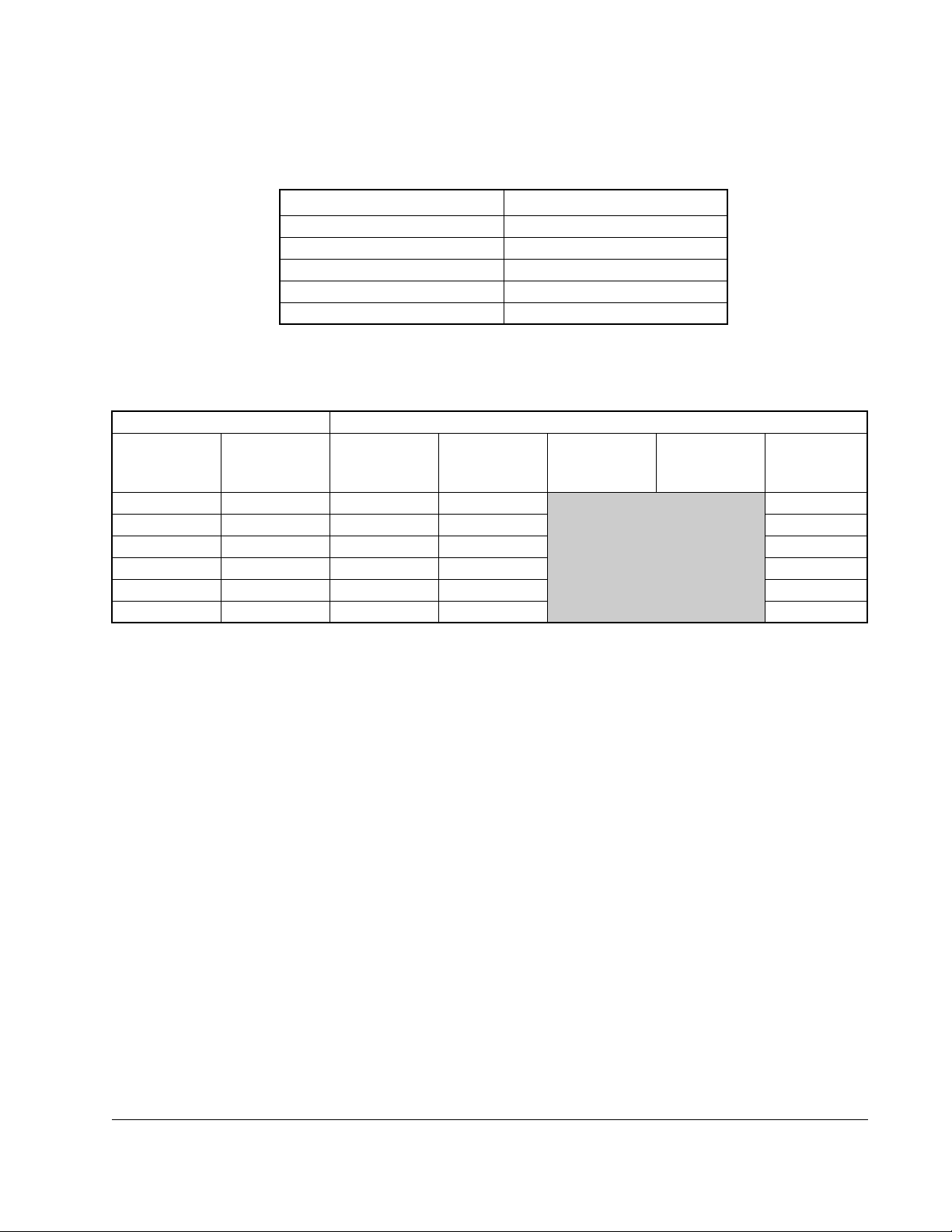
A.3 1650A Power Module Specifications
The following specifications apply to the 1650A Power Module.
Height
91.5” (2324 mm)
1
Width 75” (1905 mm)
Depth 20” (508 mm)
Shipping Weight 2500 lbs (1134 kg)
MCC Sections 3
Operating Sound Level 83 dB, wt. A
1. Note that the height of the 1650A Power Module includes a 1.5”-high base
channel.
Table A.2 – Electrical Specifications (1650A Power Module)
Input Output
Nominal
Input V oltage
(VAC)
Input Power
(kVA)
Armature
Voltage
(VDC)
Armature
Current
(ADC)
Field V oltage
(VDC)
Field Current
(ADC) Nominal HP
460 867 500 1280
460 972 500 1440 900
460 1108 500 1650 1000
575 1125 600 1330 1000
Dependent on options
selected. Refer to
section A.6.
575 1385 600 1650 1250
660 1590 700 1650 1250
800
Technical Specifications
A-5
Page 54

Power Dissipation
The 1650A Power Module dissipates power proportionally to the armature current, as
shown in figure A.5.
Heat Dissipation (W)
Armature Current (A)
Figure A.5 – Power Dissipation vs. Armature Current (1650A Power Module)
Circuit Breaker Settings
The 1650A Power Module has a 1600A R-frame circuit breaker with a 1600A plug.
The circuit breaker should be set as shown in figure A.6.
'LJLWULS 506 5DWLQJ 3OXJ
3XVK
WR
7ULS
(QJDJHG
Figure A.6 – Recommended Circuit Breaker Settings (1650A Power Module)
,Q ,U
5HPRYH
6KRUW 'HOD\
3LFNXS [ ,U
'LJLWULS 506
7ULS 8QLW
A-6
SD3100 Power Modules
Page 55

AC Input Busbars
The 1650A Power Module has two AC input busbars per phase, as shown in
figure A.7. These busbars are also used in the 1250A Power Module with the AC line
fuse option.
Bus Dimensions
0.88
1.750
Bus Arrangement
8 connections are
available for each phase
0. 83
Phase 1
(L1)
1.844
Phase 2
(L2)
0.250
0.563 Diameter
Phase 3
(L3)
Technical Specifications
Figure A.7 – AC Input Busbars (1650A Power Module)
A-7
Page 56

A.4 3000A Power Module Specifications
The following table of specifications applies to the 3000A Power Module
Height
91.5” (2324 mm)
1
Width 95” (2413 mm)
Depth 20” (508 mm)
MCC Sections 4
Shipping Weight 3500 lbs (1588 kg)
Operating Sound Level 82 dB, wt. A
1. Note that A 20”-high tophat assembly (which mounts over the disconnect bay), is
included with each 3000A Power Module.
Table A.3 – Electrical Specifications (3000A Power Module)
Input Output
Nominal
Input V oltage
(V AC)
Input Power
(kVA)
Armature
Voltage
(VDC)
Armature
Current
(ADC)
Field V oltage
(VDC)
Field Current
(ADC) Nominal HP
460 1374 500 2000
460 1634 500 2400 1500
460 2024 500 3000 1750
575 1713 600 1995 1500
575 1985 600 2330 1750
575 2254 600 2660 2000
575 2531 600 3000 2250
Dependent on options
selected. Refer to
section A.6.
660 1705 700 1715 1500
660 1971 700 2000 1750
660 2242 700 2290 2000
660 2508 700 2575 2250
660 2905 700 3000 2500
1250
A-8
SD3100 Power Modules
Page 57

Power Dissipation
The 3000A Power Module dissipates power proportionally to the armature current, as
shown in figure A.8.
Heat Dissipation (W)
Armature Current (A)
Figure A.8 – Power Dissipation vs. Armature Current (3000A Power Module
Circuit Breaker Settings
The 3000A Power Module has a 3000A SPB-frame circuit breaker. The circuit breaker
should be set as shown in figure A.9.
/RQJ 'HOD\
6HWWLQJ ,
[,
Q ,5
/RQJ 'HOD\
7LPH
5
6HF
$W
[,
5
%UHDNHU 7ULSV
$W 7
7HVW $PSV
,
Q
7HVW
7ULS 5HVHW
8QLW 6WDWXV
,QVW
6HWWLQJ
[,
Q
Technical Specifications
Figure A.9 – Recommended Circuit Breaker Settings (3000A Power Module)
A-9
Page 58

AC Input Busbars
The 3000A Power Module has a busbar arrangement allowing up to twelve
connections per phase, as shown in figure A.10.
Bus Dimensions
0.625
Diameter
Bus Arrangement
12 connections
are available for
each phase
0.88
1.750
0. 88
Phase 1
(L1)
1.938
1.938
Phase 2
(L2)
0.188
Phase 3
(L3)
A-10
Figure A.10 – AC Input Busbars (3000A Power Module)
SD3100 Power Modules
Page 59

A.5 Air Baffle Layouts
Guards
ATTENTION:
Guards are designed to direct airflow in the drive and to
prevent injury. Ensure that the guards are in place when operating the
!
Important:
drive. Failure to observe this precaution may result in bodily injury.
Air baffles are designed to distribute air to cool drive components. Ensure
that the baffles are in place when operating the drive to provide the proper
airflow and to prevent the thermoswitches or optional airflow sensor from
intermittently shutting down the drive.
The following diagrams show how the air baffles and guards are arranged in the
drives.
Baffle
Baffle
Baffle
Baffle
Baffle
Guard
Baffle
Figure A.11 – Air Baffle Layout (1250A and 1650A Power Modules)
Technical Specifications
A-11
Page 60

Guards
Baffle
Baffle
A-12
Figure A.12 – Air Baffle Layout (3000A Power Module)
SD3100 Power Modules
Page 61

A.6 Field Power Module Specifications
Ambient Conditions
•
Storage temperature: -40 to 85° C (-40 to 185° F)
•
Operating temperature: 0 to 40° C (32 to 104° F)
•
Humidity: 5 to 95%, non-condensing
•
Altitude: Up to 1000 meters (3300 feet) without derating output power. For every
91.4 meters (300 feet) above 1000 meters, derate the output current 1%.
Enclosure
•
Enclosed chassis with all circuits covered and protected.
Cooling
•
Convection cooled.
Dimensions
Part Number Height Width Depth
805405-3R 340 mm (13.4 in) 128 mm (5 in) 127 mm (5 in)
805405-5R 523 mm (20.6 in) 180 mm (7.1 in) 220 mm (8.7 in)
Input Ratings
•
AC field input voltage: 230 to 460 VAC +/- 10%, continuous operation
•
AC line frequency: 48 to 62 Hz.
•
Source rating: 2 kVA to 30 kVA
•
Maximum short circuit current: 10kA
•
Internal field fuse rating:15A unit: 20A, 600V
60A unit: 90A, 700V
•
One minute overload: 150% of maximum current (once per hour)
Output Ratings
Maximum
Part Number AC Input
805405-3R (S2R) 460V 15kW 15A
805405-5R (S2R)
1. Maximum ambient temperature with a 15° C internal maximum temperature
(Minimum Field Power Module ambient: 55° C)
Additional Information
230V 12kW 60A
460V 24kW 60A
Rated Power
Rated Current
@ 40º C
1
Technical Specifications
For additional information on DPS single-phase Field Power Modules, refer to
instruction manual S-3060.
A-13
Page 62

A-14
SD3100 Power Modules
Page 63

A
PPENDIX
B
Schematics
CB11
L1
1L1
3-Phase
AC Input
L2
L3
1L2
1L3
F17
F18
F19
F27
F28
F29
Figure B.1 – DC Blower Motor Connections
M11
M12
OL11
OL12
DC MOTOR
AC BLOWER
MOTOR
(T1)
(T2)
(T3)
DC MOTOR
AC BLOWER
MOTOR
(T1)
(T2)
(T3)
Schematics
B-1
Page 64

A
3
L
A
1
L
)
)
-
+
(
(
2
1
-
D
D
L
L
F
F
1
2
A
A
1
A
1
M
2
A
3
L
/
3
8
1
1
L
/
1
8
1
37
TB2
7
3
5
3
35
TB2
1
M
)
.
.
2
(
T
X
P
U
A
O
)
1
(
1
M
)
.
4
T
(
X
P
1
O
)
M
3
(
5
8
5
E
-
L
5
U
0
4
D
5
O
0
8
M
R
K
E
C
W
A
O
B
e
l
P
D
b
a
E
D
C
E
L
F
E
n
I
i
&
F
P
.
S
4
p
1
E
m
T
A
A
0
G
6
1
M
)
.
.
.
6
T
X
X
(
P
U
U
A
A
O
)
5
(
P
M
1
1
)
1
8
(
M
4
)
2
7
(
)
7
-
)
(
1
2
)
C
)
-
(
)
+
(
1
1
A
(
C
W
1
5
A
1
D
(
2
R
K
5
1
)
6
4
+
(
1
P
M
DCA1
S1
7
5
COM
NC.
F10B
F
5
F10A
F7B
F
2
F7A
SNUBBER
F11B
F
3
F11A
SNUBBER
)
+
(
F12A
BRIDGE
F
1
F12B
SNUBBER
2
9
1
2
X
1
:
N
1
0
R
T
0
U
0
C
T
0
A
1
4
P
S
J
1
2
P
A
A
S
1
3
B
L
L
T
5
TB2
T
P
)
)
2
4
X
H
(
(
)
3
H
C
(
A
V
)
2
H
(
)
1
X
(
SALES ORDER SPECIFIC
)
1
V
H
0
(
6
6
TB2
CB11
1
1
X
1
9
1
3
P
J
S
2
P
S
1
3
B
U
F
0
C
6
A
4
V
V
5
7
5
1
0
L
3
1
FUA
OR
AC LINE FUSES
1
L
2
6
X
9
1
1
:
3
0
T
0
0
C
0
A
1
1
5
X
9
1
2
3
L
L
1
1
2
3
L
L
SNUBBER
F8B
F
6
F8A
SNUBBER
E
G
)
D
-
I
(
R
B
F9B
F
4
F9A
)
R
(
K
G(W)
)
R
(
K
G(W)
SNUBBER
N
R
U
T
1
3
8
2
3
A
F
2
1
8
2
2
A
1
F
1
8
2
1
A
F
1
5
A
1
0
F
1
A
3
L
L1A
4
1
F
POWER
OPTIONAL
∗
E
P
4
TB10 (4-6)
A
V
4
5
2
K
T
5
62
.
P
1
TB3
....
...
)
6
)
H
2
(
2
(H5)
C
A
V
0
8
3
)
1
H
(
1
A
0
1
20
X
(
)
4
H
C
(
A
)
3
V
H
5
(
1
)
1
2
H
(
(X1)
3
6
A
1
8
F
5
)
3
1
(
0
1
1
B
3
T
5
5
7
TB3
....
...
19
4
N
1
A
N
F
A
R
F
C
S
5
COMPONENTS
2
)
H
R
(
K
2
G(W)
H
)
W
(
1
A16F
H
)
)
R
(
R
(
K
G(W)
)
R
(
K
2
G(W)
H
)
W
(
1
A13F
H
)
)
R
(
R
(
K
G(W)
3
)
1
W
(
6
1
5
3
A12F
H
0
)
0
R
6
(
-
4
3
O
1
A
M
/
4
B
2
A14F
A15F
2
A11F
)
A
H
5
)
G
1
P
W
(
(
)
R
1
H
)
R
(
2
H
)
W
(
1
H
)
R
(
H
)
W
(
1
H
)
R
(
2
A
1
A
G
5
E
I
N
F
I
I
1
L
R
A
P
P
O
T
M
T
A
U
6
O
E
P
DRIVER UNIT B/M O-805401-7
T
M
N
A
I
1
G
D
L
W
E
1
L
F
1
L
(
A
R
7
A
P
2
1
1
2
L
L
2
&
E
N
5
4
7
TB1
4
2
9
1
1
9
1
6
9
1
5
9
1
3
8
2
2
8
2
1
8
2
G
N
I
L
A
1
-
C
7
T
I
S
2
1
4
N
K
A
5
U
C
0
A
8
B
D
E
E
F
I
L
C
DC ARM
SIGNALS
A
TB1
D
A
2
1
O
L
L
C
L
A
V
R
5
E
E
E
1
T
N
N
1
I
2
1
I
L
L
I
L
L
L
F
1
L2L
5
B-2
Figure B.2 – 1250A and 1650A Power Modules (Non-Regenerative), Sheet 1
SD3100 Power Modules
Page 65
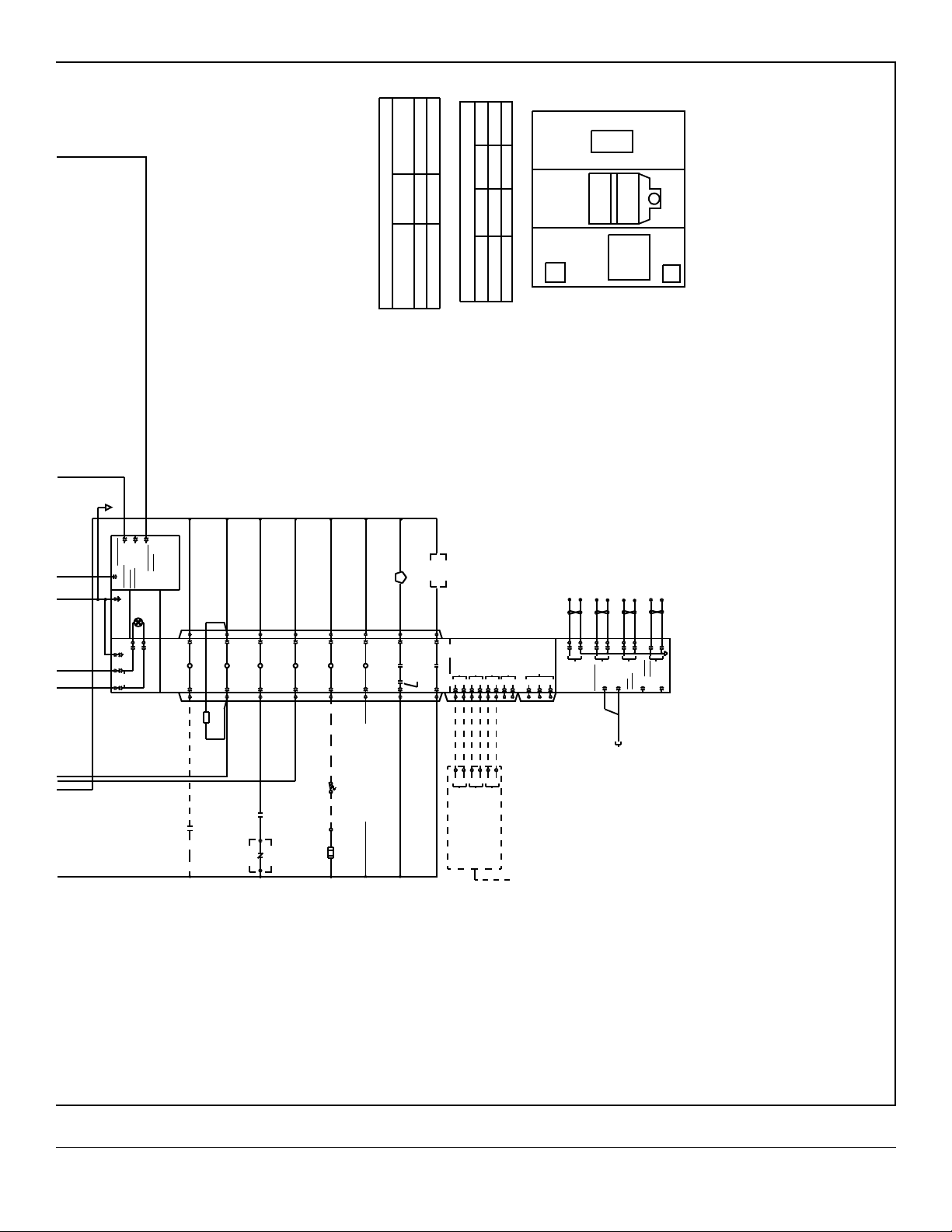
)
M
H
0
0
O
2
2
T
T
U
O
X
U
A
S
(IF USED)
E
C
N
T
E
U
R
P
E
T
F
U
E
O
R
A
(+)
(–)
213
AC
1
2
)
)
–
+
(
(
R1
INPUT
(ROTOR)
REFERENCE
(
2
R
)
K
M
R
H
0
0
O
O
2
2
(
W
1
T
R
E
N
R
)
E
D
B
F
B
3
2
U
M
(
N
C
S
R
C
S
G
N
I
0
0
T
5
5
A
6
2
R
1
1
T
I
N
U
DC MOVEMENTS
METERS ARE 10 VOLT
OPTIONAL METERS
L
A
R
)
N
E
E
1
R
N
P
T
G
T
I
-
E
U
E
U
G
3
S
T
I
P
P
N
I
S
D
B
(+)
(–)
4
C
O
X
±10V
R
ISOLATED
(
N
N
I
C
I
F
E
C
(+)
(–)
5
6
=(±2047)
E
T
N
R
P
J
H
)
)
–
+
(
(+)
(–)
(
SHLD
2
3
1
8
7
1
1
B
C
(P1)
PROCESSOR
+
B/M O-60000
1
M
N
A
F
(-) BRIDGE
(+) BRIDGE
S
'
B
C
P
2
1
3
4
567
TWISTED
COM
1
1
(C2)
TWISTED
TWISTED
+
+
COM
COM
2
3
±10V
METER
RCV
XMT
(P4)0RAIL
(P3)
(P2)
PORTS
FIBER OPTIC
COMM LINK
ORG
BLU
3
Y
A
B
2
Y
A
B
1
Y
A
B
T
P
6
8
TB6
TWISTED
+
COM
4
PORTS
1
(P5)
TB5
4
5
6
3
)
)
)
)
–
+
+
–
(
(
(
(
S1
R2
S3S4S2
SINE
COSINE
OUTPUT
OUTPUT
(STATOR)
(STATOR)
FROM UDC CARD
FIBER OPTIC COMM. LINK
BRUSHLESS
RESOLVER
INDUSTRIAL
DUTY
MOTOR
DRIVEN BY
R
R
Y
C
C
T
S
S
/
/
Q
2
2
)
2
1
F
-
7
F
(
G
E
N
0
0
S
I
S
0
3
E
T
U
8
6
S
A
F
U
R
F
R
C
S
G
0
0
T
N
I
I
5
5
N
T
6
2
1
1
A
U
R
E
P
4
K
FWD
(P3)
REV
(P2)
(P4)
ARM GATES
FLD GATES
& FDBK
DC POWER TECH
B/M O-60002
AC LINE &
DC ARM
(P1)
S
1
1
0
4
5
0
E
K
8
P
C
M
A
/
R
B
D
2
L
N
G
2
L
5
1
1
L
1
(C4)
SIGNALS
R
6
0
N
0
4
A
5
F
0
K
8
C
M
A
/
TB4
R
B
1
Y
L
L
P
N
1
P
7
A
3
0
U
F
0
0
S
O
0
0
/
I
6
6
R
-
-
)
E
E
C
O
O
1
V
A
I
W
C
M
M
(
V
R
/
/
O
D
B
B
P
TB4
4
C
A
B
D
E
E
F
R
O
T
C
A
T
N
O
C
2
4
D
B
)
1
2
N
I
I
P
-
P
X
3
R
U
C
(
)
3
C
(
1
A
C
A
3
Ω
W
K
5
7
.
.
6
4
8
4
T
A
T
T
S
A
O
T
M
S
E
R
T
L
U
A
F
D
N
U
O
R
G
6
F
2
N
I
X
U
A
E
5
O
L
E
U
M
H
D
R
T
E
O
K
H
M
T
N
I
R
S
R
E
T
O
W
A
T
E
O
O
H
P
M
0
8
1
L
J
4
3
N
N
I
I
X
X
U
U
A
A
K
H
7
9
7
(IF USED)
MOTOR THERMOSTAT
ESR
LINE
(FAIL SAFE)
EMERGENCY STOP
DOOR INTERLOCK
V
A
U
0
F
0
5
.
T
2
1
GROUND FAULT
4
P
M
3
1
)
D
E
S
U
F
I
(
2
1
N
5
N
I
X
U
A
M
1
1
(IF USED)
EXTERNAL DEVICE
EXTERNAL DEVICE
CONTACTOR PILOT
6
4
1
1
R
R
E
"
D
T
W
F
N
O
A
O
L
"
R
C
Y
E
A
C
S
L
S
E
M
E
5
O
.
D
-
0
G
I
F
F
P
P
O
R
5
3
1
1
5
Schematics
Figure B.3 – 1250A and 1650A Power Modules (Non-Regenerative), Sheet 2
B-3
Page 66

A
3
L
A
1
L
)
)
-
+
(
(
2
1
-
D
D
L
L
F
F
1
2
A
A
1
A
1
M
2
A
DCA1
F10B
F
5
R
F10A
2
SNUBBER
F11B
F
3
R
F11A
6
SNUBBER
)
+
(
BRIDGE
SNUBBER
F12A
F
1
R
F12B
4
3
L
/
3
8
1
1
L
/
1
8
1
37
TB2
7
3
5
3
35
TB2
1
M
)
.
.
2
(
T
X
P
U
A
O
)
1
(
1
M
)
.
4
T
(
X
P
1
O
)
M
3
(
5
8
5
E
-
L
5
U
0
4
D
5
O
0
8
M
R
K
E
C
W
A
O
B
e
l
P
D
b
a
E
D
C
E
L
F
E
n
I
i
&
F
P
.
S
4
p
1
E
m
T
A
A
0
G
6
1
M
)
.
.
.
6
T
X
X
(
P
U
U
A
A
O
)
5
(
F7B
F7A
F8B
F8A
1
1
)
1
8
(
M
4
)
2
7
(
7
NC.
SNUBBER
S1
COM
P
M
)
7
-
)
(
1
2
)
C
)
-
(
)
+
(
1
1
A
(
C
W
1
5
A
1
D
(
2
R
K
5
1
)
6
4
+
(
1
P
M
5
F
R
2
5
F
6
R
3
SNUBBER
E
G
)
D
-
I
(
R
B
F9B
F
4
R
F9A
1
=
9
1
D
-
R
8
7
A
3
O
1
B
5
-
H
0
C
M
A
/
E
B
)
R
(
K
(W)H2
A13R
G(W)
(R)H1
2
)
H
R
)
(
R
W
K
(
6
1
1
A
H
)
R
G(W)
(
2
)
H
R
)
(
W
K
(
1
A16F
H
)
R
G(W)
(
2
)
H
R
)
(
W
K
(
1
A13F
H
)
R
G(W)
(
SNUBBER
S
E
L
B
A
C
O
W
T
2
)
R
(
K
A15RA11R
G(W)
2
)
H
R
)
(
K
W
(
G(W)
)
R
(
K
A12R
G(W)
2
)
R
(
K
A14R
G(W)
)
R
(
K
A12F
G(W)
2
)
R
(
K
A14F
G(W)
)
R
(
K
A15F
G(W)
2
)
R
(
K
A11F
G(W)
6
H
)
5
3
W
(
1
H
)
R
(
1
H
)
R
(
2
H
)
W
(
1
H
)
R
(
H
)
W
(
1
H
)
R
(
2
H
)
W
(
1
H
)
R
(
H
)
W
(
1
H
)
R
(
2
H
)
W
(
1
H
)
R
(
H
)
W
(
1
H
)
R
(
0
1
0
6
-
3
O
4
M
/
1
B
)
4
A
G
5
P
1
(
)
R
G
5
E
N
I
I
F
1
I
R
B
L
P
O
P
T
T
U
M
6
O
P
A
M
N
E
I
1
V
T
E
A
1
R
G
(
1
L
E
7
L
L
2
A
1
R
A
2
P
3
3
1
A
6
5
3
0
0
6
-
4
O
1
M
/
4
B
)
A
DRIVER UNIT B/M O-805401-7
5
G
1
P
(
)
R
G
5
E
I
N
F
I
I
1
L
R
A
P
P
O
T
M
T
A
U
6
O
E
P
T
M
N
A
I
1
G
D
L
W
E
1
L
F
1
L
(
A
R
7
A
P
2
1
1
2
L
L
2
2
A
5
4
7
TB1
4
1
A
AC LINE &
DC ARM
SIGNALS
2
9
1
2
X
1
:
N
1
0
R
T
0
U
0
C
T
0
A
1
4
P
S
J
1
2
P
A
A
S
1
3
B
L
L
T
5
TB2
T
P
)
)
2
4
X
H
(
(
)
3
H
C
(
A
V
)
2
H
(
)
1
X
(
SALES ORDER SPECIFIC
)
1
V
H
0
(
6
6
TB2
1
1
X
1
9
1
3
P
J
S
2
P
S
1
3
B
U
F
0
C
6
A
4
V
V
5
7
5
1
0
L
3
1
FUA
OR
CB11
AC LINE FUSES
1
L
2
6
X
9
1
1
:
N
3
0
R
T
0
U
0
C
0
T
A
1
1
1
5
X
9
1
3
8
2
3
A
F
2
1
8
2
2
A
1
F
1
8
2
1
A
F
1
5
A
1
0
F
1
A
3
L
2
L
1
2
L
L1A
3
L
1
4
1
F
POWER
OPTIONAL
3
∗
L
E
P
4
TB10 (4-6)
2
A
V
4
5
2
K
T
5
6
.
P
1
TB3
....
...
)
6
)
H
2
(
2
)
(H5)
4
C
H
A
(
V
)
0
3
8
H
3
)
1
H
(
1
A
0
1
20
X
(
C
A
V
5
(
1
)
1
2
H
(
(X1)
3
6
A
1
8
F
5
)
3
1
(
0
1
1
B
3
T
5
5
7
TB3
....
...
19
4
N
1
A
N
F
A
R
F
C
S
5
COMPONENTS
2
9
1
1
9
1
6
9
1
5
9
1
TB1
3
8
2
2
8
2
1
8
2
A1
UNIT
805427-1
1
FEEDBACK SCALING
D
A
2
1
O
L
L
C
L
A
V
R
5
E
E
E
1
T
N
N
1
I
2
1
I
L
L
I
L
L
L
F
L2L
5
B-4
Figure B.4 – 1250A and 1650A Power Modules (Regenerative), Sheet 1
SD3100 Power Modules
Page 67

)
M
H
0
0
O
2
2
T
T
U
O
X
U
A
S
(IF USED)
E
C
N
T
E
U
R
P
E
T
F
U
E
O
R
A
(+)
(–)
213
AC
1
2
)
)
–
+
(
(
R1
INPUT
(ROTOR)
REFERENCE
(
2
R
)
K
M
R
H
0
0
O
O
2
2
(
W
1
T
R
E
N
R
)
E
D
B
F
B
3
2
U
M
(
N
C
S
R
C
S
G
N
I
0
0
T
5
5
A
6
2
R
1
1
T
I
N
U
DC MOVEMENTS
METERS ARE 10 VOLT
OPTIONAL METERS
L
A
R
)
N
E
E
1
R
N
P
T
G
T
I
-
E
U
E
U
G
3
S
T
I
P
P
N
I
S
D
B
(+)
(–)
4
C
O
X
±10V
R
ISOLATED
(
N
N
I
C
I
F
E
C
(+)
(–)
5
6
=(±2047)
E
T
N
R
P
J
H
)
)
–
+
(
(+)
(–)
(
SHLD
2
3
1
8
7
1
1
B
C
(P1)
PROCESSOR
+
B/M O-60000
1
M
N
A
F
(-) BRIDGE
(+) BRIDGE
S
'
B
C
P
2
1
4
678
3
5
TWISTED
COM
1
1
(C2)
TWISTED
TWISTED
+
+
COM
COM
2
3
±10V
METER
RCV
XMT
(P4)0RAIL
(P3)
(P2)
PORTS
FIBER OPTIC
COMM LINK
ORG
BLU
3
Y
A
B
2
Y
A
B
1
Y
A
B
T
P
6
TB6
TWISTED
+
COM
4
PORTS
1
(P5)
TB5
4
5
6
3
)
)
)
)
–
+
+
–
(
(
(
(
S1
R2
S3S4S2
SINE
COSINE
OUTPUT
OUTPUT
(STATOR)
(STATOR)
FROM UDC CARD
FIBER OPTIC COMM. LINK
BRUSHLESS
RESOLVER
INDUSTRIAL
DUTY
MOTOR
DRIVEN BY
R
R
Y
C
C
T
S
S
/
/
Q
2
2
)
2
1
F
-
7
F
(
G
E
N
0
0
S
I
S
0
3
E
T
U
8
6
S
A
F
U
R
F
R
C
S
G
0
0
T
N
I
I
5
5
N
T
6
2
1
1
A
U
R
E
P
4
K
FWD
(P3)
REV
(P2)
(P4)
ARM GATES
FLD GATES
& FDBK
DC POWER TECH
B/M O-60002
AC LINE &
DC ARM
(P1)
S
1
1
0
4
5
0
E
K
8
P
C
M
A
/
R
B
D
2
L
N
G
2
L
5
1
1
L
1
(C4)
SIGNALS
R
6
0
N
0
4
A
5
F
0
K
8
C
M
A
/
TB4
R
B
1
Y
L
L
P
N
1
P
7
A
3
0
U
F
0
0
S
O
0
0
/
I
6
6
R
-
-
)
E
E
C
O
O
1
V
A
I
W
C
M
M
(
V
R
/
/
O
D
B
B
P
TB4
4
C
A
B
D
E
E
F
R
O
T
C
A
T
N
O
C
2
4
D
B
)
1
2
N
I
I
P
-
P
X
3
R
U
C
(
)
3
C
(
1
A
C
A
3
Ω
W
K
5
7
.
.
6
4
8
4
T
A
T
T
S
A
O
T
M
S
E
R
T
L
U
A
F
D
N
U
O
R
G
6
F
2
N
I
X
U
A
E
5
O
L
E
U
M
H
D
R
T
E
O
K
H
M
T
N
I
R
S
R
E
T
O
W
A
T
E
O
O
H
P
M
0
8
1
L
J
4
3
N
N
I
I
X
X
U
U
A
A
K
H
7
9
7
(IF USED)
MOTOR THERMOSTAT
ESR
LINE
(FAIL SAFE)
EMERGENCY STOP
DOOR INTERLOCK
V
A
U
0
F
0
5
.
T
2
1
GROUND FAULT
4
P
M
3
1
)
D
E
S
U
F
I
(
2
1
N
5
N
I
X
U
A
M
1
1
(IF USED)
EXTERNAL DEVICE
EXTERNAL DEVICE
CONTACTOR PILOT
6
4
1
1
R
R
E
"
D
T
W
F
N
O
A
O
L
"
R
C
Y
E
A
C
S
L
S
E
M
E
5
O
.
D
-
0
G
I
F
F
P
P
O
R
5
3
1
1
5
Schematics
Figure B.5 – 1250A and 1650A Power Modules (Regenerative), Sheet 2
B-5
Page 68

A
3
L
A
1
L
)
)
-
+
(
(
2
1
-
D
D
L
L
F
F
1
2
A
A
1
A
1
M
2
A
DCA1
F10 A,B,C
F
5
R
2
SNUBBER
F11 A,B,C
F
3
R
6
SNUBBER
)
+
(
BRIDGE
F12 A,B,C
F
1
R
4
SNUBBER
3
L
/
3
8
1
1
L
/
1
8
1
37
TB2
7
3
5
3
35
TB2
1
M
)
.
.
2
(
T
X
P
U
A
O
)
1
(
1
M
)
.
4
T
(
X
P
1
O
)
M
3
(
5
8
5
E
-
L
5
U
0
4
D
5
O
0
8
M
R
K
E
C
W
A
O
e
B
l
P
D
b
a
E
D
E
C
L
F
E
n
I
i
&
F
P
.
S
4
p
1
E
m
T
A
A
0
G
6
1
M
)
.
.
.
6
T
X
X
(
P
U
U
A
A
O
)
5
(
F7 A,B,C
F8 A,B,C
E
G
)
D
-
I
(
R
B
1
1
)
1
8
(
M
4
)
2
7
(
7
NC.
SNUBBER
SNUBBER
S1
COM
P
M
)
7
-
)
(
1
2
)
C
)
-
(
)
+
(
1
1
A
(
C
W
1
5
A
1
D
(
2
R
K
5
1
)
6
4
+
(
1
P
M
5
F
2
R
5
F
6
R
3
F
4
R
1
=
9
1
D
-
R
8
7
A
3
O
1
B
5
-
H
0
C
M
A
/
E
B
)
R
(
K
(W)H2
A13R
G(W)
(R)H1
2
)
H
R
)
(
R
K
W
(
6
1
1
A
H
)
R
G(W)
(
2
)
H
R
)
(
K
W
(
1
A16F
H
)
R
G(W)
(
2
)
H
R
)
(
K
W
(
1
A13F
H
)
R
G(W)
(
F9A,B,C
SNUBBER
S
E
L
B
A
C
O
W
T
2
)
R
(
K
A15RA11R
G(W)
2
)
H
R
)
(
K
W
(
G(W)
)
R
(
K
A12R
G(W)
2
)
R
(
K
A14R
G(W)
)
R
(
K
A12F
G(W)
2
)
R
(
K
A14F
G(W)
)
R
(
K
A15F
G(W)
2
)
R
(
K
A11F
G(W)
6
H
)
5
3
0
1
W
(
1
H
)
R
(
1
H
)
R
(
2
H
)
W
(
1
H
)
R
(
H
)
W
(
1
H
)
R
(
2
H
)
W
(
1
H
)
R
(
H
)
W
(
1
H
)
R
(
2
H
)
W
(
1
H
)
R
(
H
)
W
(
1
H
)
R
(
0
6
-
3
O
4
M
/
1
B
)
4
A
G
5
P
1
(
)
R
G
5
E
N
I
I
F
1
I
R
B
L
P
O
P
T
T
M
U
6
O
A
P
M
N
E
I
1
V
T
E
A
1
R
G
(
1
L
E
7
L
L
2
A
1
R
A
2
P
3
3
1
A
6
5
3
0
0
6
-
4
O
1
M
/
4
B
)
A
DRIVER UNIT B/M O-805401-7
5
G
1
P
(
)
R
G
5
E
I
N
F
I
I
1
L
R
A
P
P
O
T
M
T
A
U
6
O
E
P
T
M
N
A
I
1
G
D
L
W
E
1
L
F
1
L
(
A
R
7
A
P
2
1
1
2
L
L
2
&
2
A
5
4
7
TB1
4
1
A
E
N
I
L
C
DC ARM
SIGNALS
A
2
9
1
2
X
1
:
N
1
0
R
T
0
U
0
C
T
0
A
1
4
P
S
J
1
2
P
A
A
S
1
3
B
L
L
T
5
TB2
T
P
)
)
2
4
X
H
(
(
)
3
H
C
(
A
V
)
2
H
(
)
1
X
(
SALES ORDER SPECIFIC
)
1
V
0
H
(
6
6
TB2
CB11
1
X1
1
9
1
3
P
J
S
2
P
S
1
3
B
U
F
0
C
6
A
4
V
V
5
7
5
1
0
L
3
1
FUA
OR
AC LINE FUSES
1
L
2
6
X
9
1
1
:
N
3
0
R
T
0
0
U
C
0
T
A
1
1
1
5
X
9
1
3
8
2
3
A
F
1
2
8
2
2
A
1
F
1
8
2
1
A
F
1
5
A
1
0
F
1
A
3
L
2
L
1
2
L
L1A
3
L
1
4
1
F
POWER
OPTIONAL
3
∗
L
E
P
4
TB10 (4-6)
2
A
V
4
5
2
K
T
5
6
.
P
1
TB3
....
...
)
6
)
H
2
(
2
)
(H5)
4
C
H
A
(
V
)
0
3
8
H
3
(
)
2
H
(
)
1
H
(
1
A
0
1
20
X
(
C
A
V
5
1
1
(X1)
3
6
A
1
8
F
5
)
3
1
(
0
1
1
3
B
T
5
5
7
TB3
....
...
19
4
N
1
A
N
F
A
R
F
C
S
5
COMPONENTS
2
9
1
1
9
1
6
9
1
5
9
1
TB1
3
8
2
2
8
2
1
8
2
G
N
I
L
A
1
-
C
7
T
I
S
2
1
4
N
K
A
5
U
C
0
A
8
B
D
E
E
1
L
F
D
A
1
2
O
L
L
C
L
A
V
R
5
E
E
E
1
T
N
N
1
I
2
1
I
L
L
I
L
L
L
F
2
L
5
B-6
Figure B.6 – 3000A Power Module (Regenerative), Sheet 1
SD3100 Power Modules
Page 69

40
R4(OHM)
Y
T
QTY
Q
3/SCR
0
0
9
FUSE
RATING
SCR FUSES (F7-F12)
0
0
0
3
UNIT
RATING
40
R3(OHM)
∗
E
T
5
O
40
T
P
M
E
R2(OHM)
R
40
R1(OHM)
SCR SNUBBER NETWORK
3
C (MFD)
CB11
0
0
0
3
M1
FAN
(-) BRIDGE
(+) BRIDGE
BAY 3
BAY 2
BAY 2
DPS
PCB'S
BAY 1
2
T
P
UNIT RATING
E
P
4
K
FWD
(P3)
REV
(P2)
(P4)
ARM GATES
FLD GATES
& FDBK
DC POWER TECH
B/M O-60002
AC LINE &
DC ARM
(P1)
S
1
1
0
4
5
0
E
K
8
P
C
M
A
/
R
B
D
2
L
N
G
2
L
5
1
1
L
1
(C4)
SIGNALS
R
6
0
N
0
4
A
5
F
0
K
8
C
M
A
/
TB4
R
B
1
Y
L
L
P
N
1
P
7
A
3
0
U
F
0
0
S
O
0
0
/
I
6
6
R
-
-
)
E
E
C
O
O
1
V
A
I
W
C
M
M
(
V
R
/
/
O
D
B
B
P
TB4
4
C
A
B
D
E
E
F
R
O
T
C
A
T
N
O
C
2
4
D
B
)
1
2
N
I
I
P
-
P
X
3
R
U
C
(
)
3
C
(
1
A
C
A
3
Ω
W
K
5
7
.
.
6
4
8
4
T
A
T
T
S
A
O
T
M
S
E
R
T
L
U
A
F
D
N
U
O
R
G
6
F
2
N
I
X
U
A
E
5
O
L
E
U
M
H
D
R
T
E
O
K
H
M
T
N
I
R
S
R
E
T
O
W
A
T
E
O
O
H
P
M
0
8
1
L
J
4
3
N
N
I
I
X
X
U
U
A
A
K
H
7
9
7
(IF USED)
MOTOR THERMOSTAT
ESR
LINE
(FAIL SAFE)
EMERGENCY STOP
DOOR INTERLOCK
V
A
U
0
F
0
5
.
T
2
1
GROUND FAULT
4
P
M
3
1
)
D
E
S
U
F
I
(
2
4
1
1
N
5
N
I
X
U
A
M
1
3
1
1
(IF USED)
EXTERNAL DEVICE
(IF USED)
EXTERNAL DEVICE
CONTACTOR PILOT
6
1
T
R
R
C
M
P
E
R
E
C
"
D
T
N
T
W
F
N
T
E
U
O
A
U
O
R
L
O
P
"
C
E
Y
E
T
F
E
A
S
X
N
U
L
E
S
E
5
.
D
-
0
F
F
O
I
E
U
O
R
S
O
A
G
D
B
A
I
(+)
(–)
P
(+)
(–)
S
R
5
4
213
1
AC
1
4
2
3
)
)
)
)
–
+
–
+
(
(
(
(
R1
S1
R2
SINE
OUTPUT
INPUT
(ROTOR)
REFERENCE
OPTIONAL METERS
L
A
R
)
N
E
E
1
R
N
P
T
G
T
I
-
E
U
U
G
3
S
T
I
P
P
C
O
X
R
(
N
N
I
C
E
T
I
F
E
J
C
H
)
+
(+)
(–)
(
(+)
(–)
1
8
5
6
7
5
6
)
)
–
+
(
(
S3S4S2
COSINE
OUTPUT
(STATOR)
(STATOR)
1
2
4
678
3
5
DC MOVEMENTS
METERS ARE 10 VOLT
TWISTED
+
COM
(P1)
1
1
±10V
ISOLATED
=(±2047)
N
R
P
)
–
(
SHLD
PROCESSOR
B/M O-60000
(C2)
2
3
TWISTED
TWISTED
+
+
COM
COM
2
3
RCV
XMT
(P3)
(P2)
PORTS
FIBER OPTIC
COMM LINK
ORG
BLU
TB6
TWISTED
+
COM
4
±10V
METER
PORTS
1
(P4)0RAIL
(P5)
TB5
FROM UDC CARD
FIBER OPTIC COMM. LINK
BRUSHLESS
RESOLVER
INDUSTRIAL
5
DUTY
MOTOR
DRIVEN BY
Schematics
Figure B.7 – 3000A Power Module (Regenerative), Sheet 2
B-7
Page 70

B-8
SD3100 Power Modules
Page 71

A
PPENDIX
Replacement Parts
C.1 Regulator Assembly
Please refer to the following instruction manuals for replacement parts information:
Component M anual Number
PMI Rack and Modules S-3008
Parallel Gate Amplifier Rack and
Modules
C.2 Field Power Module Replacement Parts
15 Amp, S2R Field Power Module (#805405-3R)
Description Part Number
AC Input Line Fuses (2) 64676-3CL
Power Cubes (3)
FPC1 (1,2,3,4 THY)
RPC1 (11,12,13,14 THY)
CLAMP (Q1,Q2)
Field Gate Coupling Card B/M O-60014 - ∗∗
Hall Device Assembly 615051-R
PMI Cable
1. Specify cable length in inches
∗∗
Revision level
1
701819-303AW
612418-S
S-3045
C
Replacement Parts
60 Amp, S2R Field Power Module (#805405-5R)
Part Description Reliance Part Number
AC Input Line Fuses (2) 64676-130ASX
Power Cubes (5):
(FPC1 - 1,4THY)
(FPC2 - 3,6THY)
(RPC1 - 11,14THY)
(RPC2 - 13,16THY)
(CLAMP - Q1,Q2)
Field Gate Coupling Card B/M 60033-∗∗
Snubber P.C. Board B/M 60034-∗∗
Gate Pin Extension (10) 615050-15R
37 (+) Cable Assembly 805417-R
PMI Cable
1. Specify required length in inches.
∗∗
Revision level
1
701819-201AW
612418-S
C-1
Page 72

C.3 Spare Parts Kits
Current
Type of Kit
Line RC Suppressor
(Option 14LSP)
Air Flow Switch PCB
(Option 14AFL)
Air Flow Switch
(Option 14AFL)
Line MOVs R,S,T 2300-SPJ02A 2300-SPJ03A 2300-SPJ04A 1 set
Armature SCRs
Positive (Top)
Regenerative Armature
Assemblies
Negative (Bottom)
Regenerative Armature
Assemblies
Positive (Top) NonRegenerative Armature
Assemblies
Negative (Bottom) NonRegenerative Armature
Assemblies
Bridge Fan
Bridge Fan Door Filter T 2361-SPK02A 2361-SPK02A 2361-SPK0 2A
Slide-In Fan T 2361-SPH03A 2361-SPH03A 2361-SPH03A
Loose Power Fuses
Power Fuse Assembly T 2361-SPE11A 2361-SPE11A 2361-SPE11A
Input Line Fuses
Snubber Assembly
1. R = 1250A, S = 1650A, T = 3000A.
2. Drive requires 12 fuses.
3. Drive requires 18 fuses.
1
Code
R,S,T 2300- SPB01A 2300-SPB01A 2300-SPB02A 1 PCB with 2 sets of fuses
R,S 2300-SPP01A 2300-SPP01A 2300-SPP01A 1 PCB with 0.5A power supply
T 2300-SPP02A 2300-SPP02A 2300-SPP02A 1 PCB with 1.1A power supply
R,S 2300-SPK03A 2300-SPK03A 2300-SPK03A
T 2300-SPK01A 2300-SPK01A 2300-SPK01A
R 2361-SPG01A 2361-SPG01A 2361-SPG01A 2 SCRs
S 2361-SPG02A 2361-SPG02A 2361-SPG02A 2 SCRs
T 2361-SPG03A 2361-SPG03A 2361-S PG03A 2 SCRs
R SD3100-SPA01A SD3100-SPA01A SD3100-SP A01A
S SD3100-SPA05A SD3100-SPA05A SD3100-SPA05A
T 2361-SPA05A 2361-SPA05A 2361-SPA05A
R SD3100-SPA02A SD3100-SPA02A SD3100-SP A02A
S SD3100-SPA06A SD3100-SPA06A SD3100-SPA06A
T 2361-SPA06A 2361-SPA06A 2361-SPA06A
R SD3100-SPA03A SD3100-SPA03A SD3100-SP A03A
S SD3100-SPA07A SD3100-SPA07A SD3100-SPA07A
R SD3100-SPA04A SD3100-SPA04A SD3100-SP A04A
S SD3100-SPA08A SD3100-SPA08A SD3100-SPA08A
R,S 2361-SPH01A 2361-SPH01A 2361-SPH01A
T 2361-SPH02A 2361-SPH02A 2361-SPH02A
R 2361-SPE08A 2361-SPE08A 2361-SPE08A
S 2361-SPE09A 2361-SPE09A 2361-SPE09A
T 2361-SPE10A 2361-SPE10A 2361-SPE10A
R 2361-SPE12A 2361-SPE12A 2361-SPE12A
S 2361-SPE13A 2361-SPE13A 2361-SPE13A
T 2361-SPE14A 2361-SPE14A 2361-SPE14A
R 2361-SPB03A 2361-SPB03A 2361-SPB03A
S 2361-SPB01A 2361-S PB 01A 2361-SPB01A
T 2361-SPB02A 2361-SPB02A 2361-SPB02A
460 VAC 575 VAC 660 VAC Brief Description
Fiberglass 20” x 30” x 1”, 1
required, 6 per kit.
2 fuses per kit
2 fuses per kit
3 fuses per kit
1 assembly containing 3 fuses in
parallel
2
2
3
C-2
SD3100 Power Modules
Page 73

I
NDEX
A
AC input busbars
1250A Power Module, A-4
1650A Power Module, A-7
3000A Power Module, A-10
connecting AC input wires to, 3-3
Air baffles, A-11 to A-12
Altitude derating chart, A-1
Analog input connections (TB5), 3- 6
Armature power components, 2-4 to 2-7
bridge components, 2-6 to 2-7
B
Blower motor connections, B-1
C
Circuit breaker, 2-3
Circuit breaker settings
1250A Power Module, A-3
1650A Power Module, A-6
3000A Power Module, A-9
Component replacement, 4-4 to 4-6
Field Power Module, 4-5
Parallel Gate Amplifier, 4-5
PMI regulator, 4-5
spare parts kits, 4-4
Control components, 2-2 to 2-3
Control power and field supply tap, 2-4
D
DC drive binder (S-3000), 1-4
Diagnostics, 4-2 to 4-4
Drive I/O connections (TB4), 3-6
E
Electrical description, 2-7 to 2-8
conduction timeout, 4-3
instantaneous over cu rren t, 4-3
loss of field, 4-3
shorted SCR, 4-2
Feedback devices, 3-6
Field isolation transformer, 3-4
Field Power Module
AC line input fuses, 4-5
component replacement, 4-5
electrical description, 2-8
introduction, 1-3
mechanical description, 2-7
part numbers, 1-3
replacement parts, C-1
specifications, A-13
G
Grounding, 3-7 to 3-8
I
Installation guidelines, 3-1 to 3-8
AC input power, 3-2 to 3-3
AC input wire selection, 3-2
analog input, 3-6
armature and field wire selection, 3-5
connecting the AC busbars, 3-3
drive I/O, 3-6
feedback devices, 3-6
field isolation transformer, 3-4
field power module, 3-4
grounding the drive, 3-7
making an input entry hole, 3-3
meter ports, 3-7
motor connection and wiring, 3-5
physically installing the Power Module, 3-2
planning the installation, 3-1
resolver, 3-6
Introduction, 1-1 to 1-5
Isolation transformer, 3-4
requirement for, 2-3
F
Faults, 4-2 to 4-3
AC line synchronization, 4-2
Index
M
Main components of Power Module, 2-1
Index-1
Page 74

Maintenance and troubleshooting, 4-1 to 4-6
component replacement, 4-4 to 4-6
faults, 4-2 to 4-3
Field Power Module, 4-5
PMI rack and modules, 4-5
recommended test equipment, 4-1 to 4-2
system diagnostics, 4-2 to 4-4
warnings , 4-3 to 4-4
Mechanical description, 2-2 to 2-7
Meter port connections, 3-7
Motor control center documentation, 1-5
Motor installation, 3-5
N
component reference, 2-19
configurations, 2-17
description, 2-17
dimensions, 2-20
schematics, B-6 to B-7
technical specifications, A-8 to A-10
R
RC suppressor, 2-4
Regenerative armature bridge, 2-6
Related publications, 1-4
Replacement parts, C-1 to C-2
Resolver connections (TB5 ), 3-6
Non-regenerative armature bridge, 2-5
O
Optional features, 1-4
P
Power components, 2-3 to 2-7
armature power, 2-4 to 2-7
incoming power, 2-3 to 2-4
Power dissipation
1250A Power Module, A-3
1650A Power Module, A-6
3000A Power Module, A-9
Power Module - 1250A
component layout, 2-10
component reference, 2-11
configurations, 2-9
description, 2-9
dimensions, 2-12
schematics, B-2 to B-5
technical specifications, A-2 to A-4
Power Module - 1650A
component layout, 2-14
component reference, 2-15
configurations, 2-13
description, 2-13
dimensions, 2-16
schematics, B-2 to B-5
technical specifications, A-5 to A-7
Power Module - 3000A
component layout, 2-18
S
Schematics, B-1 to B-7
Spare parts kits, 4-4, C -2
Standard features, 1-3
Start-up, 3-8
T
Technical specifications, A-1 to A-10
1250A Power Module, A-2 to A-4
1650A Power Module, A-5 to A-7
3000A Power Module, A-8 to A-10
Field Power Module, A-13
general specifications, A-1
Terms used in this manual, 1-5
Test equipment, 4-1 to 4-2
W
Warnings, 4-3 to 4-4
current reference limit warning, 4-4
fan loss, 4-4
Field Power Module overcurrent, 4-4
identification test error, 4-4
low line voltage/phase missing, 4-3
synchronization loss fault avoided, 4-4
three-phase bridge SCR not firing, 4-3
Wires
for AC input, 3-2
for armature and field lines, 3-5
Index-2
SD3100 Power Modules
Page 75

DIF
Documentation
Impro vement Form
Use this form to give us your comments concerning this publication or to report an
error that you have found. For convenience, y ou may attach copies of the pages with
your comments. After you have completed this form, please return it to:
Rockwell Automation
RGA (Technical Publications)
25001 Tungsten Road
Cleveland, Ohio 44117
Fax: 216.266.7120
Publication Name:
Publication Number: Publication Date:
Comments:
Your Name: Date:
Company Name: Phone: ( )
Address:
Thank you for your comments.
Technical Writing Internal Use
Date: DIF Number:
Follow-Up Action:
Page 76

Rockwell Automation
Printed in U.S.A. S-3064 July 1998
/ 24703 Euclid Avenue / Cleveland, Ohio 44117 / (216) 266-7000
 Loading...