

Page 1

User Manual
SSCCDD OOppeerraattiinngg SSooffttwwaarree
SSaaffeeZZoonnee™™MMuullttiizzoonnee aanndd
SSaaffeeSShhiieelldd™™SSaaffeettyy LLiigghhtt CCuurrttaaiinn
Page 2

Important
User Information
Because of the variety of uses for the products described in this publication, those
responsible for the application and use of this control equipment must satisfy
themselves that all necessary steps have been taken to assure that each application
and use meets all performance and safety requirements, including any applicable
laws, regulations, codes and standards.
The illustrations, charts, sample programs and layout examples shown in this
guide are intended solely for purposes of example. Since there are many variables
and requirements associated with any particular installation, Rockwell A utomation
Allen-Bradley does not assume responsibility or liability, including intellectual
property liability for actual use based upon the examples shown in this
publication.
Related Safety Information
You are responsible for the safety of the entire installed control system and for
meeting all applicable laws, codes, and safety requirements.
ATTENTION: As the installer of this control system, you
must be knowledgeable of other applicable standards pertaining
to safety recommendations related to:
• Machine Construction
• General Electrical
• Machine Guarding
• Point of Operation guards, safety light curtains, mechanical
guards, and Two hand controls
In addition to local laws and codes, you are responsible for the
safety recommendations detailed in all applicable codes and
standards including:
• OSHA Regulations
•ANSI Standards
•NFPA
•CSA
IMPORTANT Rockwell Automation reserves the right to make revisions
to these installation instructions and disclaims liability for all
incidental and consequential damages related to the
furnishing, performance and use of this material.
Page 3

SCD Operating Software User Manual
Table of Contents
About this Documentation . . . . . . . . . . . . . . . . . . . . . . . . 4
Installation of the Software . . . . . . . . . . . . . . . . . . . . . . . . 6
Product Description. . . . . . . . . . . . . . . . . . . . . . . . . . . . . . 6
User Interface. . . . . . . . . . . . . . . . . . . . . . . . . . . . . . . . . . . 6
Working with Projects . . . . . . . . . . . . . . . . . . . . . . . . . . . . 8
Communication . . . . . . . . . . . . . . . . . . . . . . . . . . . . . . . . . 9
Configuration . . . . . . . . . . . . . . . . . . . . . . . . . . . . . . . . . . 10
Diagnosis Data. . . . . . . . . . . . . . . . . . . . . . . . . . . . . . . . . 12
All specifications subject to change.
IMPORTANT: Save these instructions for
use at a future time.
Generally recognized technical regulations and quality
assurance system ISO 9000 are carefully applied during the
development and produ ction of Rockwell Automation
products.
3
Page 4

SCD Software User Manual
About This Documentation
Please read this chapter carefully before working with this
documentation and the Safety Configuration & Diagnostic (SCD)
software.
Function of This Document
This manua l instruct s the mach ine opera tor’s technic al person nel in
the operation of the SCD software for safety devices supplied by
Allen-Bradley Guardmaster.
It does not provide instructions on the operation,
commissioning and maintenance of the safety devices
themselves. Please refer to the doc u m entation encl o sed
with the safety devices for information on operation,
commissioning and maintenance.
Target Group
This software documentation addresses planners, developers and
operators of systems which are to be protected by one or more
safety devices supplied by Allen-Bradley Guardmaster.
It also addresses persons who integrate these safety devices into a
machine, start it up for the first time, or who are in charge of
servicing and maintaining the unit.
ATTENTION helps you
• Identify a hazard
•Avoid a hazard
• Recognize the consequences
IMPORTANT: Identifies information that is especially important
for successful application and unders tanding of the product.
Display indicators show the status of the 7-segment
display of sender or receiver:
Constant display of the letter F
Flashing display of the letter F
Alternating display of F and 2
LED symbols denote a flashing LED (upright
orientation, 7-segment display, bottom)
➢ Take action...
Instructions for taking action are shown by an arrow. Carefully
read and follow the instructions for action.
Note Refer to Notes for special features of the software or of
the device.
Information Depth
This software documentation conta ins information o n the SCD
software for safety devices supplied by Allen-Bradley Guardmaster.
The manual provides an overview of the basic software functions.
Please refer to the online h elp function for more detailed
instructions on the configuration and diagnosis of devices.
Planning and using safety devices also require specialized technical
skills which are not conveyed in this documentation.
Abbreviations
SCD Safety Configuration & Diagnostic software
Symbols and Formats Used
Throughout this manual we use the labels ATTENTION and
IMPORTANT to alert you to the following:
ATTENTION!
Failure to observe may r esult in danger ous operati on
ATTENTION: Identifies information about practices of
circumstances that can lead to personal injury or death, property
damage, or econ omic loss
Handling the Online Help Function
The SCD software is available with an online help function which
provides information on the softwar e fun ctions and which pr o vides
a step-by-step description of the indi vidual actions.
The following sections of the documentation can be opened in the
list of contents:
• Manual on the SCD software in Portable Document Format
(PDF)
• Operating instructions for the devices supplied by Allen-Bradley
Guardmaster Safety Systems in Portable Document Format
(PDF)
• Online help on the SCD
• Online help on device-specific subjects (configuration
procedures)
The online help function can be opened separately using the
command Programs, Allen-Bradley Guardmaster
Applications, Help on Allen-Bradley Guardmaster SCD.
4
Page 5

• Online help on the SCD
• Online help on device-s pecific subjects (e.g. configuration
procedures)
• Operating instructions for the devices supplied by Allen-Bradley
Guardmaster Safety Systems in Portable Document Format
(PDF)
SCD Operating Software User Manual
Manuals
Safety Configuration & Diagnostic Software
On the documentation
User interface
Overview
User interface
Menu, symbol and status bar
Navigation and viewing area
Printer setup
Selecting the language
Keyboard commands
Directory structure of the program
Working with projects
Configuration
Diagnosis data
Figure 1: List of contents of the online help
Figure 3: T opics found in dialog box
The step-by-step instructions describe th e rel ated pro cedur e in
detail.
SCD software
Figure 4: Example of step-by-step instructions
As the SCD is used for the configuration and diagnostics on a
number of protective devices from Rockwell Automation, along
with the basic description there are device-specific help subjects.
From these basic descriptions you can open the device-specific help
subjects using the Device-specific subje cts link at the end of a
dialog box description.
Figure 5: Device-specific subjects link
The Contents button in the dialog box descriptions and in the
step-by-step instructions will always take you back to the list of
contents.
The online help function can be opened separately using the
command Programs, Allen-Bradley Guardmaster
Applications, Help on Allen-Bradley Guardmaster SCD or
in the SCD in the menu ?. From one of the SCD dialog boxes, click
the Help butto n in the dialog box or press t h e F1 key. T he related
description for the dialog box is then displayed automatic ally.
The descriptions in the online help explain the functions and
relationships in the dialog boxes. Use the Detailed instructions
button in the descriptions to go to the step-by-step instructions
of the online help.
Figure 2: Detailed instructions button
If several sets of step-by-step instructions are available, the Topic s
found dialog box is opened. Choose there the required topic and
click the Display button.
Figure 6: Contents button
Once back in the list of contents and in the appropriate dialog
box descriptions, you can also open the operating instruct ions for
the desired protective devices.
To do so, you must have the related file in PDF format and Adobe
®
Acrobat
warning is dis p layed.
Reader™ installed on your PC. If this is not the case, a
How to Use this Document
After you have carefully read the above sections, please note the
following notes on the document.
• If the software is as yet not installed, please read the chapter
Installation in this us er manual.
• If you are working with the software for the first time, please
read the chapter Product descriptio n.
• If you are familiar with the software and want to configure
devices, please read the chapter Configuration.
• If you are familiar with the software and want to perform
diagnostics on devices, please read the chapter Diagnostics.
5
Page 6

SCD Operating Software User Manual
Installation of the Software
An installation wizard will guide you through the installation of the
software. Before beginning the installation, close all other
programmes.
The minimum system requirements for the operation of the SCD
Software are:
• Standard Intel Pentium PC , 233 MHz, 64 MB RAM
• Spare ha rd disk space (SCD = 15 MB/documentation G 100 MB)
• Graphics resolution 800 × 600 pixels with High Color (16 bit)
• RS 232 serial interface that is not used by any other programs
• Operating system MS Windows 95/98/NT4.0/2000/XP
• A printer driver of your choice must be installed.
Note During the installation you can install Acrobat
®
Reader™.
Using this program you can read the user manual for the
SCD and the operating instructions for devices from AllenBradley Guardmaster Safety Systems.
How to install the SCD:
• Start your PC and place the installation CD in your CD-ROM
drive. The in stalla tion wiz ard wi ll start aut omatic ally. It allows y ou
to open the documentation and to install the software.
• First enter the serial number for the SCD. You will find the
number on the CD jacket with the installation CD.
• Then, go to the dialog box Allen-B radley Guard master SCD
and select Install software, Allen-Bradley Gua rdma ster
SCD and cli ck the OK button bes i de the selectio n.
• Follow the instructions in the installation wizard.
• During the installation of the SCD, choose the software
components to be installed (i.e., SafeShield, SafeZone multizone)
software that has already been installed with a pr evious v ersion of
the SCD are selected automatically and updated as necessary.
• If Windows does not start the installation wizard automatically:
Click Run... in the Start menu. Enter the following command
line in the Open field: [Drive letter for your CD-ROM
drive]:\setup.exe. The Serial number dialog bo x will open.
Product Description
Devices from Allen-Bradley Guardmaster Safety Systems such as
safety light curtains or safety laser scanners can be configured
differently depending on the application and operating mode.
• Create a new project, configure the de vic es and later transfer
the configuration to the devices. You can then save the project
created.
• Identify devices connected to the PC and receive the existing
configuration of the devices, and then transfer it back to the
devices. In this way a new project is created in the SCD that you
can save.
• Open a project saved previously and transfer the configuration
to devices of the same type (with the same type code) and for
the same application.
The configuration of the devices is password-protected, with the
effect that only the members o f the appropriate user groups will
be able to transfer configurations to the devices.
You can also use the SCD software to perform diagnostics on
connected devices (e.g. in the case of an error). The diagnostics
data will be displayed on the monitor.
Project
Identify New Open
• Connect PC to
device(s)
• Receive configuration
• Log on
• Edit configuration
• Transfer configuration
• Save project
• Add device(s)
• Create configurati o n
• Connect to device(s)
• Log on
• Transfer configuration
• Save project
• Connect to device(s)
•Log on
• Transfer configuration
Figure 7: Typical procedure in the SCD
ATTENTION: Test the devices for
operational readiness!
The software is unable to determ ine if a devi ce is
mounted operationally or not. Once you have
successfully transferred the configuration drafts,
check to see if the Allen-Bradley Guardmaster
protective devices actually m onitor your machine
or system the way you intended.
In this case pay attention to the instructions on commissioning
and for the daily check in the operating instructions for the
related device!
All values have been computed by the PC on which the SCD
runs. Allen-Bradley Guardmaster is therefore unable to warrant
that no computer-specific computing errors will occur.
The SCD software has a graphic user interf ace which allo ws you to
configure and diagnose devices supplied by Allen-Bradley
Guardmaster Safety Systems. The param eters for a configuration
are transferred to the devices and saved there.
Note The software is not suitable for the configuration and
diagnostics of devices supplied by other manufacturers.
The devices in the SCD software are always di splayed in so-called
projects. The SCD software allows you to …
6
User Interface
How to Start the Software:
➢ Go to the Start menu and select the command Programs,
Allen-Bradley Guardmaster Applications, Allen-Bradley
Guardmaster SCD software. The Safety Configuration &
Diagnostic Software will now be started.
Page 7

Once the program has started, the screen is initially blank. Device
combinations saved or identified will eventually be shown
graphically in the user interface. These can then be used to
configure or diagnose Allen-Bradley Guardmaster safety devices.
SCD Operating Software User Manual
Figure 10: Status bar with symbols for “not connected” and
“configur a ti on no t verif ied ”
Allen-Bradley Guardmaster SCD
Figure 8: User Interface of the SCD software
The user interface includes title bar, menu bar, tool bar, the
navigation area, the viewing area and the status bar.
How to close the software:
➢ On the Project menu choose the Quit command. The
program wi ndo w will be closed. If, at this point, y o u have not as
yet saved the data of an open project, you will be prompted to
do so.
Menu, Tool and Status Bars
The menu bar and the tool bar are found at the top of the software
window . The menu bar incl udes the commands for t he fundamental
operation of the software, whereas the tool bar pr ovides the most
important commands in the shape of buttons. Moving o ver a button
will open a brief information tag (tool tip) on the function of the
button.
The status bar is at the bottom of the software window. There the
following is displayed:
• The status of the program execution and progress if the action is
protracted
• The user group to which you currently belong
• The name of the project or device in the navigation area
• Whether the SCD is connected to a device
• Whether the configuration has been verified
Figure 9: Status bar with symbols for “connected” and “configuration
verified”
The tool bar and the status bar can be shown or hidden.
Navigation and Viewing Area
The navigation area shows the devices in a device cluster
hierarchically in a project tree. This project tree consists of a
project symbol and one or several device symbols.
In the navigation area you can open various c o mmands using the
context menus for the project or the devices.
Note If some commands are only displayed in grey, then the
commands are currently not available (because the SCD,
for example, is not connected to a device) or your access
rights are inadequate.
The viewing area is located to the right of the navigation area and is
initially blank. In the viewing area of the SCD...
• The diagnostics data is displayed when you have performed
diagnostics.
• The configuration protocol i s displayed when you have
transferred a configuration to a device.
• The parameters for a devi ce are displayed when you click one of
the device parameter nodes.
• The configuration data currently in the SCD is displayed when
you display the configuration draft for a device.
Note Only when it is indicated in the status line that the SCD is
linked to the connected devices and that the configuration
draft is verified, it is ensured that the data displayed for a
parameter node or the configuratio n draft matches the
data in the devices.
Figure 11: Status bar with symbols for “connected” and “configuration
verified”
You can change the size ratio of navigation area and viewing area.
Keyboard Commands
The SCD allows you to execute frequently used functions via
function keys or with key shortcuts.
Function Key or
Shortcut Description
Ctrl+N Create new project
Ctrl+O Open existing project
Ctrl+S Save project
F1 Open the help utility
F3 Identify connected project
7
Page 8
SCD Operating Software User Manual
Function Key or
Shortcut Description
Shift+F3 Select communication connection
F4
F6 Display pr op erties of a project or device
F7 Open the context menu
F8 Change user group
Alt+F4 End SCD
Esc
Link connected project with open
project
Close dialog box without saving
Cancel
Table 1: Function keys and key shortcuts
Directory Structure for the Program
To make it easier for you to navigate through created projects,
device configurations, diagnostics r eports, etc., the program
creates a directory structure in the directory chosen during
installation.
This directory structure consists of subdirectories for the
individual types of files that you are allowed to save in the SCD:
• Backup: This directory holds the program files of an earlier
version sa ve d after an update. You must not save an y oth er files in
this directory!
• Device-specific directories: This directory includes
subdirectories that are suggested as the directory when saving
device-specific files, e.g. diagnostics report or configuratio n
protocol.
• Import-export: SCD default
configuration drafts.
• Projects: SCD default for saving project files.
• System: This directory holds the system-specific SCD files. You
must not save any other files in this directory!
for importing and/or exporting
• During project identification, the softwar e onl y identifies the typ e
of devices connected. To ensure that you receive the
configuration of the connected devices in the SCD, the software
will pr ompt y ou t o receive the current configuration. This is
important as otherwise an “empty” configuration draft is
displayed by the SCD, and not the configuration draft that was
transferred to the device connected during earlier configuration.
Once the configuration has bee n rece ived, you are prompted as to
whether you want to change to a different user group. You can
only later transfer a new or changed configuration draft if you
change to the Authorized client user group.
IMPORTANT Check identification of the devices!
Check to make sure that all devices in the
project hav e been correctly identified. Compar e
the devices connected with the data in the
viewing area for the SCD.
You can save the projects in files and open them again later. Only
one project at any one time can be opened in the SCD. If a project
is open while opening or creating another project, the or iginal
project will be closed.
When you open an existing pr oject or add a ne w p roject, then you
should connect the devices displayed to the de vices connect ed. By
connecting you will be able to verify that the connected devices and
the devices shown in the project tree have matching type code.
You can also compare a project saved and/o r opened in the SCD
with a saved project file.
In addition, you can open a list showing the properties of a
project or of a single device.
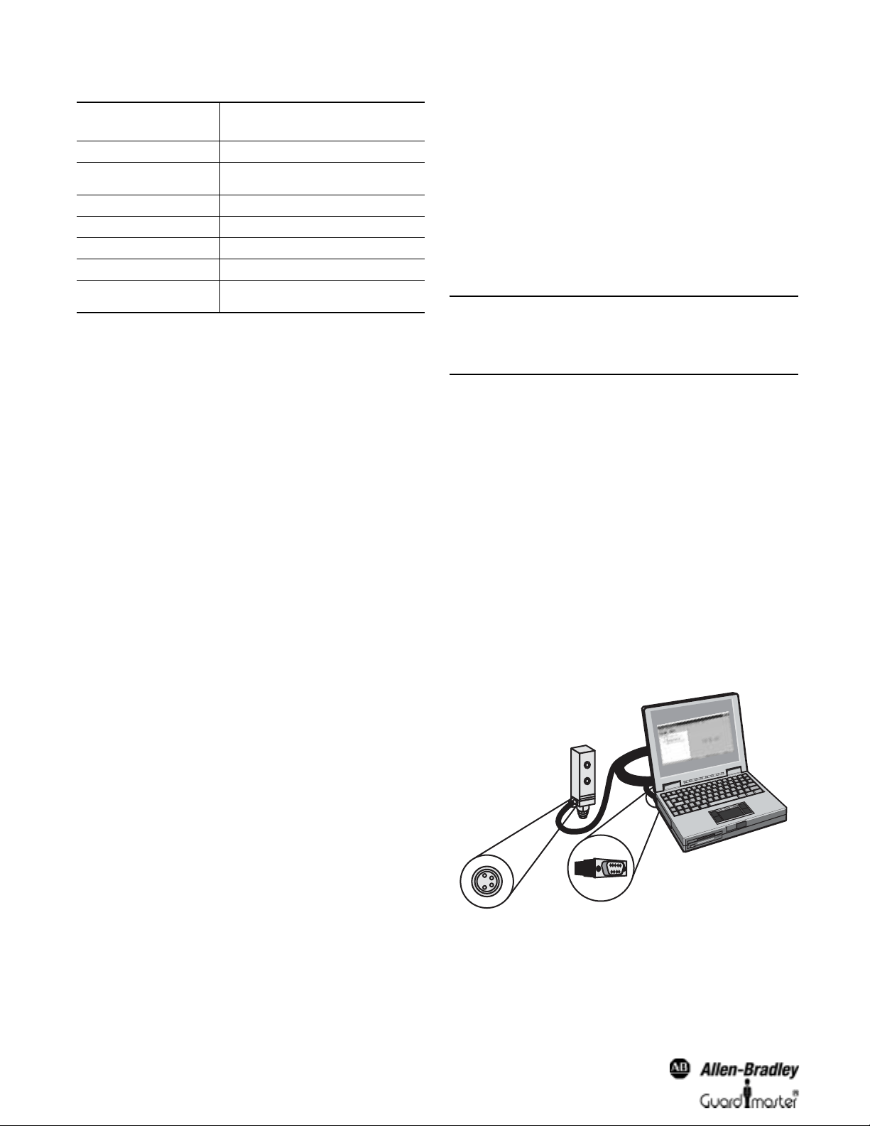
How to connect the PC to a device from Allen-Bradley
Guardmaster Safety Systems:
• Connect the 9-pin SubD plug of the connecting cable to a serial
interface of your PC.
Working with Projects
The devices which you configure, maintain or perform diagnostics
with the SCD software are managed in projects and shown in a
project tree.
Using the SCD software you can assemble pr ojects offline, and then
configure and save them. In this way, for example, for the initial
configuration of Allen-Bradley Guardmaster protective devices for
equipment, you can first plan the configuration on the screen and
later transfer it to one or more (identical) devices. When the
project is created, it is given a name that you can change. Add
devices to the project tree of a new project.
A second way of creating a project is to have the SCD identify
devices already wired up. In this way a project with all identified
devices is displayed in the navigation area of the SCD.
The commands necessary to carry out the above-described
functions are found in the Project menu. Please refer to the online
help for a device-specific description and detailed instructions.
8
Figure 12: Connection of the PC e.g. to a device from Allen-Bradley
Guardmaster Safety Systems
• Remove the protective cap on the configuration socket of the
device supplied by Allen-Bradley Guardmaster Safety Systems.
• Connect the M 8
× 4 plug to the configuration socket of the
device and/or the device cluster.
Page 9

SCD Operating Software User Manual
Note Ensure that the configur ation cable is not laid in close
proximity to high po w er electric al driv es or cables car rying
high power. In this way you will avoid EMC effects on the
configuration cable.
Note When devices—consisting of senders and receivers—are
involved, initially connect the receiver because it needs to
be configured first.
The Project Tree
The project tree of the devices is shown in the navigation area.
The devices existing in the project tree can be displayed in the
“active” or in the “passive” mode:
Example Symbols Meaning
Active devic es are shown in color.
Active means that the device has a
complementary uni t to which a
connection has been made via the
interface an d that the complementary
unit has been identified by the SCD.
Passive devices are shown in gray.
Passive means that there i s at pre sent no
connection to this device, either because
it is currently disconnected or because it
could not be identified. This is important
particularly in devices such as the
SafeShield saf ety light curtain that
consists of sender and receiver. As the
PC with th e SC D c an be co nn ec t ed only
to the sender or the receiver, the
complementary uni t is always shown in
the passive mode.
Comparing with a Project File
You can also compare a project saved and/o r opened in the SCD
with a saved project file.
A dialog box will show the saved project on the left and on the
right a comparison protocol.
In this dialog box you can open the project file compared with the
open project.
Adding Devices
If you have created your own project in the SCD, you can also add
one or several devices. The device selection wizard will assist you
in this step.
The class of devices you can select there will depend on which
device classes have been installed.
Added devices can be deleted again from the project.
IMPORTANT The commands necessary to carry out the
above-described functions are found in the
context menu of the pro ject. Please re fer to the
online help for det ailed instructions.
Properties
To check the type codes and the serial numbers of the devices, yo u
can display the properties of a project and/or the properties of a
single device. The list shows all type codes and the serial numbers
of the devices.
You can identify the device to which the
PC is connected by the device symbol
showing a PC .
Unknown or unidentified devices are
shown with a question mark.
Table 2: Meaning of the symbols
The device status is symbolized by the color of the lettering:
Font Color Meaning
(Blue) [protective device]
(Red) [protective device]
(Grey) [protective device]
Configured devices are shown with blue
lettering.
Nonconfigured devices or devices in
which a malfunction has occurred are
shown with red lettering.
Devices where the SCD is unable to
identify their status (not connected, not
identified) are shown with grey lettering.
Table 3: Meaning of the font colors
Changing Pr oject Names
You can change the name of a project. When a projec t is sa ve d, the
SCD uses the project name as the default file name. For the project
name, use names, for instance, with which you can allocate your
projects to the machines or equipment that are protected.
Communication
The software communicates with the devices via a cable link. To
make sure that the data communication between your PC and the
connected devices functions properly, you m ust sel ect a
communication protocol.
IMPORTANT On the Extras menu of the SCD, you will find
the Communication connection...
command. Please refer to the online help for
detailed instructions.
9
Page 10

SCD Operating Software User Manual
Note You can transfer the configuration draft to devices or a
device system only if your PC is connected to the devices
and if you are registered as user in the appropriate user
group of the devices.
The configuration draft of a single devi ce can also be exported and
imported to other devices with the same type code.
V erified Configuration Draft
As soon as a configuration draft has been sent and released by an
Authorized client, it is deemed to be verified. Y o u can see this by a
green tick or check in the status bar.
Figure 13: Selecting the communication protocol
• For the other Allen-Bradley Guardmaster devices ,
choose the communication protocol Serial
communication (RK 512).
In addition, you must specify one COM port of your PC as the
connection for the devices.
Also, from the connections available on your PC, select the one
where the devices are connected.
Note The connection you select must not be used by any other
peripheral (e.g. a mouse). If you do, the system will not
function properly.
Configuration
Using the SCD you can configure the All en-Bradley Guardmaster
protective devices.
ATTENTION: Plan your configuration caref ul l y!
The configuration of Allen-Bradley Guardmaster
safety devices must be carried out with ultimate
accuracy and must match the status and the
condition of the m achine or system to be
monitored.
Incorrect configurations may result in injury or
death.
Always begin by creating a new configuration draft in the SCD
software or by editing a configuration draft received from the
devices.
Generate or edit the configuration draft either with the help of the
configuration wizard or in a configuration dialog box with
file cards.
For the actual configuration of the devices supplied by AllenBradley Guardmaster Safety Systems, transfer the configuration
draft to the connected devices. After sen ding the configuration
draft, a configuration protocol will be displayed which you must
first release before the configuration is enabled in the devices.
Figure 14: Status bar with checkmark for “configuration verified”
The project with the verified configuration draft can then be saved
and later be sent also to o ther devic es b y the mach ine mainten ance
personnel.
Note When a project is opened the green check mark in the
status line is only displayed after the SCD is linked to the
related device.
If the open configuration draft is changed, a red cross appears in the
status line. The configuration dra ft can no longer be transferred by
machine maintenance personnel.
IMPORTANT The commands necessary to carry out the
above-described functions are found in the
context menus of the device symbols. Please
refer to the online help for a device-specific
description and detailed instructions.
File Cards or Assistant
You can create the configuration draft per device from AllenBradley Safety Systems either with the help of the configuration
wizard or with the file cards.
• The configuration wizard will guide you step-by-step through the
configuration, from the first to the last setting. You will find
explanatory text on the individual configuration steps in the
related dialog box.
• The file cards allow you specifically change one or several
configuration parameters.
IMPORTANT Check the content of all file cards!
Unlike the configuration wizard, in the file card
view you are n ot automatically guided through
all configuration points.
For this reason check the content on all file
cards to ensure that the configuration data
matches your application.
Note The commands necessary to carry out th e abov e-described
functions are found in the menu View, Dialog Bo x
menu
10
Page 11

SCD Operating Software User Manual
Note A system with several devices (for example a cascaded
system) is in general configured in one single configuration
wizard or one single dialog box with file cards. Several
runs through the setting dialog boxes will be completed.
Respectively the file card s will be repeatedly offered.
Figure 15: Dialog box for the configuration wizard based on the example
of the SafeZone multizone
configuration draft, it will be shown in red. In this case the
configuration protocol cannot be released.
You can print and save the configuration protocol. You can also
insert a comment via an additional dialog box. This comment will
also be printed and saved.
IMPORTANT Carefully check the conf iguration protocol!
Carefully check to make sure that the
configuration data displayed comply with those
you actually wanted to enter. Check for typing
and transfer errors!
Once you have successfully transferred the
configuration, the machine or equipment must
be checked and released by specialist
personnel.
Note The new configuration will be activated on the device only
after release. If you reject the configuration, then the
device or device cluster receives an invalid configuration.
The commands necessary to carry out the above-described
functions are found in the Project menu and in the context
menus of the devices.
• Carefully check each individual item of the configuration
protocol.
• Some configuration protocols for devices have several pages. In
this case page to the previous/following pages using the buttons
at the bottom of the scroll bar or us ing the Page up/Page down
keys.
Figure 16: Dialog with file cards based on the example of the SafeShield
Configuration Protocol
As soon as the configuration protocol or the view containing the
configuration draft is displayed, the standard menus in the software
are hidden. Only the Project menu with the appropriate buttons
will then be available. The navigation area of the SCD can no longer
be used.
After the configuration data has been transferred to one or sev eral
devices, the configurati on protocol will be shown automatically.
During this process the actual data is read out fro m the devi ce and
displayed.
If the data read does not match the data in the configuration draft,
it will be shown in b lack. If the data r ead out di ffers fr om th at in the
Figure 17: Buttons for paging through the configuration protocol
• Also carefully check the following pages of the configuration
protocol. The Acknowledge button only becomes available
when you have paged through to the last page of the
configuration protocol.
• Click the Acknowledge button. The configuration data will be
loaded to the device/devices and initialized with the new
configuration.
If the loading has been successful, an appropriate message will
appear.
• Click the OK button. The configuration loaded to the device/
devices is now active.
• Test whether the device(s) monitor the machine or equipmen t as
you expect. Only after completing this step, go to real-time
operation.
User Groups
There are various user groups in the devices from Allen-Bradley
Guardmaster Safety Systems. These user groups have different
authorizations, e.g. for transferring c onfigurations to the de vices or
to perform diagnostics on the devices.
If the devices in a pr oject ha v e been identified b y the SCD softwar e,
or the SCD is linked to th e devices for a p r oject, y ou can change to
these user groups. When the SCD is started, y ou will auto matically
11
Page 12

SCD Operating Software User Manual
belong to the user group Machine operator. To be able to send
configurations, log in with the device or the device system as
Machine mainten ance personnel or as Authorized client, using the
appropriate project password.
The factory-set password ABGM has been entered for the
user group Authorized client.
Note If a device cluster has been assembled using devices which
have already been configured, the individual devices may
have different passwords. In this case you will be asked for
your password separately for each device.
Once you have entered the correct passwords for all
devices, the passwor d for the first device will be assig ned to
all devices.
ATTENTION: Change the Machine
operator user group!
If you leave the PC unattended when it is
connected to devices, you must change to the
Machine operator user group in order that no
unauthorized persons can trans fer configurations
to the devices!
Change Project Password
The user group Authorized client can enter/change the passwords
for the user groups Machine maintenance personnel and
Authorized client. The passwords will be saved in the devices. This
allows the devices to be protected from being configured by
unauthorized persons.
You can print and save the diagnostics data. You can also insert a
comment via an additional dialog box. This comment will also be
printed and saved.
The commands necessary to carry out the above-described
functions are found in the contex t menu of the devices under
Diagnostics. Please refer to the online help for a specific
description and detailed instru ctions.
Comments
You can add comments to the reports displayed in the viewing area
of the SCD . These commen ts ar e also printed with the a ppro priate
report and saved.
Reset Password
If you have forgotten the password for a device, you can reset the
password. To do so, you need what is called a reset password. You
will get this password once you have identified yourself in writing to
the manufacturer.
For this purpose use the form Faxform.pdf on the SCD CD-ROM.
For the identification you will need the serial number of the device
and the number of the device counter (Dev ice-counter-nr.). Both
numbers can be found in the Reset password dialog box.
Note When you reset the password for a device, it is configured
as on delivery! For operation to be possible you must reedit the configura tion as delivered, or transfer a suitable
previously saved and verified configu ration to the device.
Diagnosis Data
With the aid of the SCD you can perform diagnostics on devices
connected and linked to the SCD (or identified by the SCD). To do
so, load the diagnostics data to the viewing area of the monitor.
As soon as the diagnostics data is displayed, the standard menus of
the software will disappear. Then only the Project menu and the
related buttons are available . The navigation area of the SCD can
no longer be use d.
12
Page 13

Page 14

Please contact us for Technical Assistance:
In the U.S.: 1-440-646-5800
Outside U.S.: 001-440-646-5800
On line: http://www.ab.com/safety
75035-143-01(C) April 2005
Copyright © 2005 Rockwell Automation. All right reserved. Printed in USA
 Loading...