

Page 1

Trusted™
PD-8161
Trusted™ / SC300E Bridge Module
Introduction
The SC300E Bridge presents a new opportunity to combine the SC300E Triguard I/O structure with the
latest processing and communications features of Trusted™.
Combining the two products will enable Triguard users to benefit from features such as 3-3-2-0
Processor fault tolerance, IEC 1131 programming suite, Ethernet networks, OPC, Ethernet peer to
peer and remote diagnostics. The SC300E Bridge replaces the Triguard MPP in the Triguard Primary
chassis.
Any system using the SC300E Bridge and Trusted™ TMR Processor can also include Trusted™
Expanders and I/O modules forming a Hybrid system. To the Trusted™ TMR Processor, the Trusted™
and SC300E chassis appear in the same system map. All systems using Trusted™ TMR Processors
can be seamlessly integrated together.
Features
• Triple Modular Redundant (TMR), fault tolerant (3-3-2-0) operation
• Dedicated hardware and software test regimes which provide very fast fault
recognition and response times
• Automatic fault handling without nuisance alarming
• Hot replacement, self-configuration.
• Interfaces to Trusted™ TMR Expander Bus
• Front panel indicators that show module health data transmission status
• TÜV certification and IEC61508 SIL3
Issue 2 Feb 10 PD-8161 1
Page 2
Trusted™ Bridge Module 8161
Issue Record
Issue
Number Date Revised by Technical CheckAuthorised by Modification
1 Apr 08 A Holgate N Owens P Stock Initial Issue
2 Feb 10 A Holgate N Owens P Stock TC-322 details
Issue 2 Feb 10 PD-8161 2
Page 3

Trusted™ Bridge Module 8161
Table of Contents
1. Description......................................................................................................................................7
1.1 Overview.........................................................................................................................................7
1.2 Power Distribution ..........................................................................................................................8
1.3 Communication Busses..................................................................................................................8
1.3.1 The Trusted™ to SC300E Primary Chassis...................................................................................8
1.3.2 Inter-Module Link (IML) ..................................................................................................................8
1.4 Function..........................................................................................................................................8
2. Installation ......................................................................................................................................9
2.1 Module............................................................................................................................................9
2.2 TC-322-02 Interface Cable assembly...........................................................................................10
2.3 Module Configuration ...................................................................................................................11
3. Application ....................................................................................................................................12
3.1 System Configuration ...................................................................................................................12
3.2 Board Definitions ..........................................................................................................................16
3.2.1 Module – 8161 (Bridge Module) ...................................................................................................17
3.2.2 Module – MBB (Bus interface Module).........................................................................................18
3.2.3 Module – mai32lad (0-5V; analogue input Module)......................................................................19
3.2.4 Module – mai32mad (0-10V; analogue input Module) .................................................................20
3.2.5 Module – mai32nad (0-20Ma; analogue input Module)................................................................21
3.2.6 Module – mai32pad (0-40Ma; analogue input Module)................................................................22
3.2.7 Module – mao04nnd (0-22Ma; analogue output Module) ............................................................23
3.2.8 Module – mdi32bis (24v; digital input Module) .............................................................................25
3.2.9 Module – mdi32fis (120v; digital input Module) ............................................................................26
3.2.10 Module – mdi32gis (48v; digital input Module) .............................................................................27
3.2.11 Module – mdi64bns (24v simplex; digital input Module)...............................................................28
3.2.12 Module – mdo16fns (120v; digital output Module) .......................................................................30
3.2.13 Module – mdo16gns (48v; digital output Module).........................................................................32
3.2.14 Module – mdo32bns (24v; digital output Module).........................................................................34
3.2.15 Module – mhb44ind (Pulse-in/analogue output Module) ..............................................................36
3.2.16 Module – mrb01xs (remote slave Module)...................................................................................38
3.2.17 Module – mrb04xm (remote master Module)...............................................................................39
4. Operation......................................................................................................................................40
4.1 Front Panel Indicators and Controls.............................................................................................41
4.1.1 Tx & Rx Indicators ........................................................................................................................41
4.1.2 Health Indicator ............................................................................................................................41
4.1.3 On-Line Indicator and Switch .......................................................................................................41
5. Fault Finding and Maintenance ....................................................................................................42
Issue 2 Feb 10 PD-8161 3
Page 4

Trusted™ Bridge Module 8161
6. Specifications ...............................................................................................................................43
Figures
Figure 1 Block Diagram showing interface between Trusted™ system and Triguard I/O...................... 7
Figure 2 8161 Bridge Module ................................................................................................................. 9
Figure 3 TC-322-02 Interface Cable assembly..................................................................................... 10
Figure 4 Triguard main chassis rear view............................................................................................. 10
Figure 5 Trusted™ controller chassis rear view ................................................................................... 11
Figure 6 Chassis Address Jumpers...................................................................................................... 11
Figure 7 Trusted™ Processor Chassis with Expander Interface.......................................................... 12
Figure 8 Insert New Chassis................................................................................................................. 12
Figure 9 Triguard main chassis ............................................................................................................ 13
Figure 10 Chassis Connection.............................................................................................................. 13
Figure 11 Connected Chassis .............................................................................................................. 13
Figure 12 Jumper Setting ..................................................................................................................... 14
Figure 13 MBB and MRB04XM Chassis Addressing ........................................................................... 14
Figure 14 Triguard Modules.................................................................................................................. 15
Figure 15 Module Options .................................................................................................................... 15
Figure 16 Front Panel Layout ............................................................................................................... 40
Tab le s
Table 1 Bridge Module Associated Equipment....................................................................................... 6
Issue 2 Feb 10 PD-8161 4
Page 5

Trusted™ Bridge Module 8161
Precautionary Information
WARNING
Warning notices call attention to the use of materials, processes, methods, procedures or limits which
must be followed precisely to avoid personal injury or death.
CAUTION
Caution notices call attention to methods and procedures which must be followed to avoid damage to
the equipment.
Notes:
Notes highlight procedures and contain information to assist the user in the understanding of the
information contained in this document
Warning
RADIO FREQUENCY INTERFERENCE
Most electronic equipment is influenced by Radio Frequency Interference (RFI). Caution should be
exercised with regard to the use of portable communications equipment around such equipment.
Signs should be posted in the vicinity of the equipment cautioning against the use of portable
communications equipment.
MAINTENANCE
Maintenance must be performed only by qualified personnel, otherwise personal injury, death, or
damage to the system may be caused.
Caution
HANDLING
Under no circumstances should the module housing be removed.
Associated Documents
Product Descriptions (PD) provide product specific information.
The Safety Manual contains the recommended safety requirements for the safety system design.
The PD-T8082 – Toolset Suite provides specific guidance on system configuration and application
generation.
The Operator and Maintenance Manual contains general guidelines on maintenance and diagnostic
procedures.
For technical support email: support@icstriplex.com
Issue 2 Feb 10 PD-8161 5
Page 6

Trusted™ Bridge Module 8161
Associated Equipment
Part Number Product Name Description
Adds equipment definitions for SC300E modules
o the Trusted™ Toolset
T8042 SC300E Toolset Library
CS300/SC300E Interface Cable
TC-322-02
TC-325-02
Assembly
SC300E Interface Cable
Connector Card
Table 1 Bridge Module Associated Equipment
t
To connect between Trusted™ Expander
nterface Adaptor and SC300E Controller
I
Chassis
To attach TC-322-02 cable to SC300E Controller
Chassis
Issue 2 Feb 10 PD-8161 6
Page 7
Trusted™ Bridge Module 8161
Module
Bridge Module (A)
Backplane
1. Description
1.1 Overview
The SC300E Bridge enables connection between a Triguard SC300E I/O sub system and the
Trusted™ TMR Processor. Three SC300E Bridge modules replace the three MPP modules in a
Triguard primary chassis.
The Bridge module has a fast serial ("Hotlink") interface that transfers command and response packets
between the two product families via the Trusted™ Expander Bus. The module uses a Field
Programmable Gate Array (FPGA) for decoding instructions from the Trusted™ TMR processor,
accessing the specified Triguard I/O module and returning any data requested.
Command data received by the three Bridge modules and responses to the Trusted™ TMR Processor
are synchronised in accordance with the Lock Step operational characteristics of the Trusted™
Expander Bus. For this reason, the three bridge modules share their data and arrange their response
packets in the same order for simultaneous transmission. The clock signal received from the Expander
Bus is used to ensure that data from all three Bridge modules is transmitted on the same clock edge.
The Trusted™ TMR processor stores and executes the application program, scans and updates the
Triguard I/O modules and detects system faults. Each of the three slices of the TMR Processor
executes the application program independently, but in lock-step synchronisation with the other two.
All Triguard I/O modules are supported. Triguard Serial Communication modules are not supported. All
communications to workstations and DCS systems are enabled through the Trusted™
Communications Interfaces.
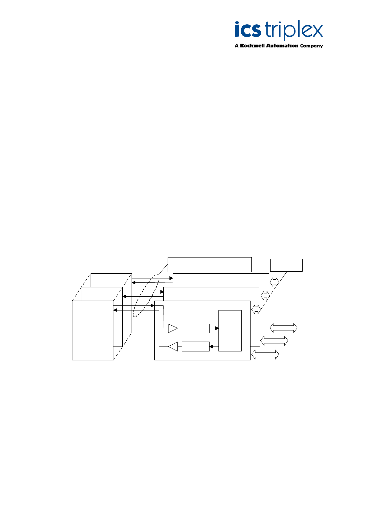
(B)
(A)
FCR A
Trusted™
Expander
Interface
Trusted™
Main Chassis
(C)
FCR A
Expansion Bus (T C-322-02 Cable)
transmitter
Main Chassis
(TC-325-02 Board)
Bridge Module (C)
Bridge Module (B)
hotlin k
receiver
hotlin k
Triguard
FPGA
Inter Mod ule
Link
Triguard
to T riguard
I/O Modules
Figure 1 Block Diagram showing interface between Trusted™ system and Triguard I/O
Issue 2 Feb 10 PD-8161 7
Page 8

Trusted™ Bridge Module 8161
1.2 Power Distribution
Each of the Bridge modules is powered from dual redundant 5.4V dc via the backplane from the
chassis PAC or PDC dual power supplies.
1.3 Communication Busses
1.3.1 The Trusted™ to SC300E Primary Chassis
Communication between the Trusted™ Expander Interface Module and the SC300E Primary Chassis
is via one of a possible four or seven triplicated two-way interface cables. A single backplane
connector card routes the individual links in the cable to the three Bridge modules. Data voting is
provided at the Expander Module Interface to ensure that cable faults are detected.
The link handles the following triplicated signals:
Data - Serial bi-directional bus.
Control - Bus clocks, module-enables and bus direction control.
Slot - Indicating the SC300E I/O slot position to the Bridge.
Expander Chassis ID - 4 bit Trusted™ chassis address code.
1.3.2 Inter-Module Link (IML)
When returning data for Trusted™ Read requests, I/O Module data received by each Bridge module is
shared with the other two using the serial IML via the backplane. The three sets of data are then
arranged sequentially into the response packet for Trusted™. The IML is not used during Write
requests.
1.4 Function
When an I/O access is to be performed, the Trusted™ TMR Processor issues a command packet to
an Expander Interface module. The Expander Interface decodes the chassis address and transmits
the packet through the Expander bus to receivers in the 8161 Bridge modules.
For short distances of a few metres, a twisted-pair copper cable is used, whilst on longer runs the
copper cable is connected to three T8312 fibre optic units at each end of three pairs (Tx and Rx) of
fibre optic cable. The Bridge modules, receiving the command signals, decode the packet.
The Bridge modules then implement the read or write access on the SC300E I/O module selected and
return a response packet via the Expander Bus. The packet will contain both data and diagnostic
information.
Issue 2 Feb 10 PD-8161 8
Page 9
Trusted™ Bridge Module 8161
2. Installation
2.1 Module
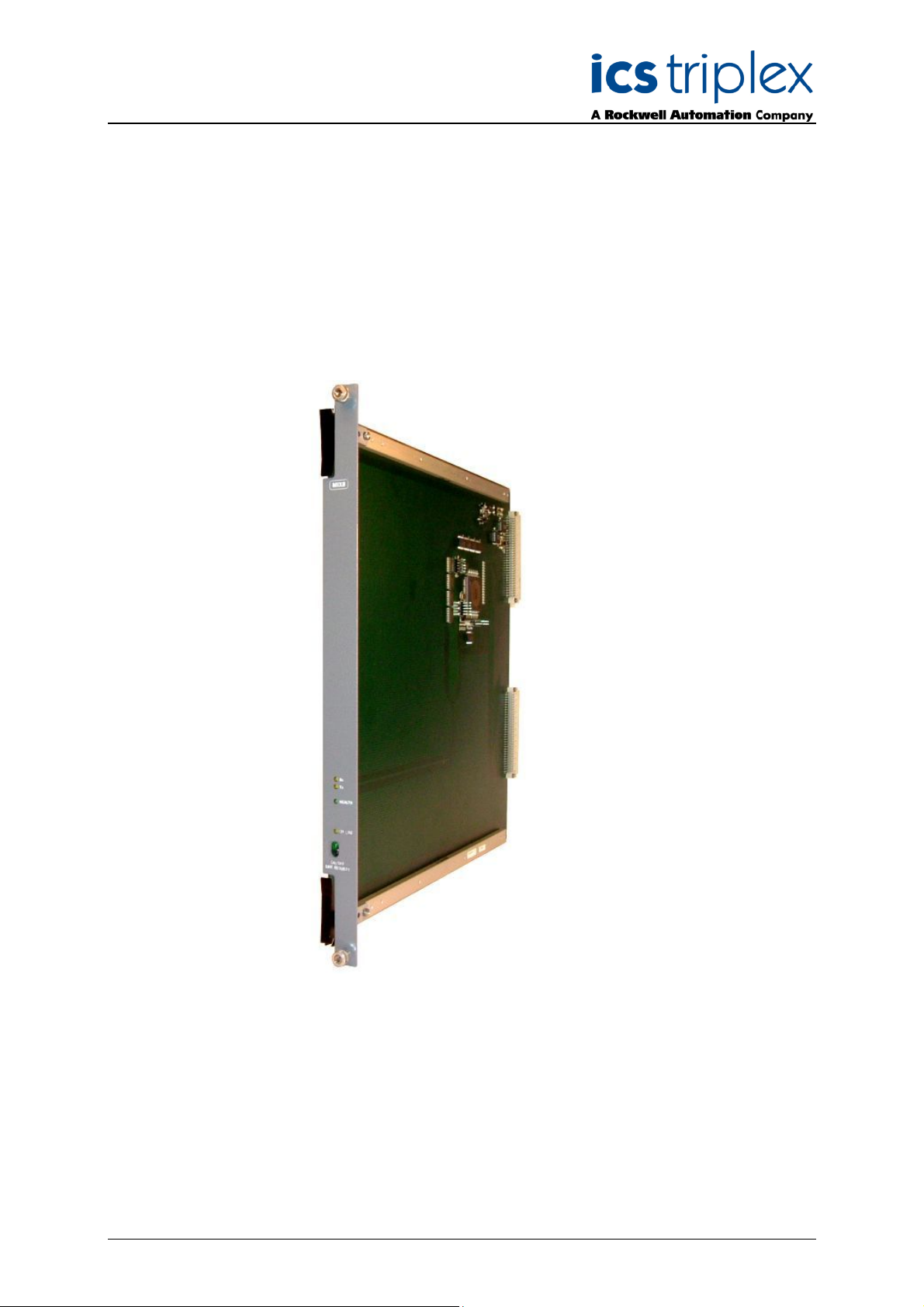
Each of the three Bridge modules replaces one of the Triguard MPP processors. Figure 2 shows the
module. The replacement must be carried out with the system offline.
The modules consist of a single PCB assembly.
Figure 2 8161 Bridge Module
Issue 2 Feb 10 PD-8161 9
Page 10
Trusted™ Bridge Module 8161
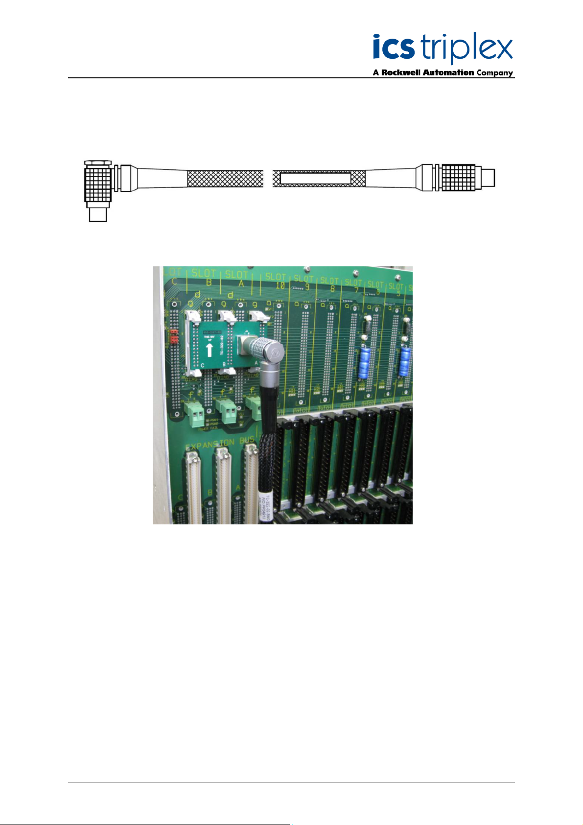
2.2 TC-322-02 Interface Cable assembly
The interface cable connects from the Trusted™ Interface Adaptor T8312 to an identical 12 way
socket on the interface cable connector card.
Figure 3 TC-322-02 Interface Cable assembly
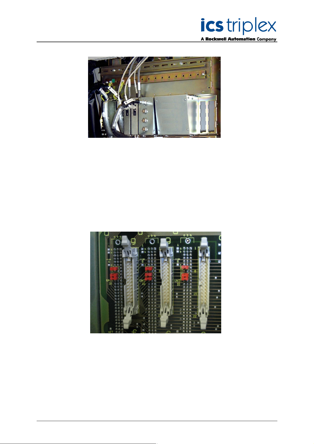
Figure 4 Triguard main chassis rear view
Figure 4 shows the interface cable connector card (top left) fitted to three unused connectors on the
rear of the Triguard controller chassis which is connected to the Trusted™ Expander Interface adaptor
via the TC-322-02 interface cable (braided cable on left).
Connectors J1-3 on the TC-325-02 card plug into the three 26-way headers on the Triguard backplane.
The expander cable, TC-322-02, from the Trusted™ Expander Interface plugs into 12-way socket J4.
Note that the chassis Unit ID jumpers will need setting before fitting the interface cable connector card
(see section 2.3).
Issue 2 Feb 10 PD-8161 10
Page 11
Trusted™ Bridge Module 8161
Figure 5 Trusted™ controller chassis rear view
Figure 5 shows a four socket version of the T8312 Expander Interface Adaptor with a TC-301-01 cable
attached, which connects to a Trusted™ expander chassis. The Expander Interface Adapter has four
or seven connections available to individual Trusted™ Expander chassis or to the Triguard controller
chassis using the TC-322-02 Interface Cable Assembly.
2.3 Module Configuration
The Bridge module requires minimum configuration, namely the setting of Unit ID jumpers 0 to 3 to
define the chassis address to Trusted™. These are situated on the Triguard chassis as shown here.
Figure 6 Chassis Address Jumpers
Unit ID jumpers 0,1,2,3 represent the binary address bits 1,2,4 & 8 respectively. A removed jumper
signals a binary digit ‘1’. The address is set to between 2 and 8. On the first Triguard chassis
(containing the SC300E Bridge Modules), remove jumper 1 to represent Trusted™ address '2' (as
shown in the picture). The jumpers on all three sets must be set to the same address. Leave the
jumpers as they were on the other Triguard chassis. It is usual to attach the chassis with address 2 to
the first Expander Interface Adapter socket, for both Trusted™ chassis and Triguard chassis. This
makes the software configuration easier.
Issue 2 Feb 10 PD-8161 11
Page 12
Trusted™ Bridge Module 8161
3. Application
All Triguard I/O modules are configured using the IEC1131 application Toolset provided with
rusted™. This configuration requires entries in the System Configuration (System.INI) for the chassis
T
and modules and their hardware operational parameters, and also in the workbench I/O connection
table, for software settings and data connection.
3.1 System Configuration
All Trusted™ systems need a system configuration file, specifying the chassis and modules in the
system. For Trusted™/Triguard hybrid systems, a T8311 Expander Interface is required in the
Trusted™ controller chassis, as for Trusted™-only systems. An example with Expander Interfaces in
slots 1 and 2 (companion slots) and communications interfaces in slots 7 and 8, is shown below. For
details of the System Configuration Tool please refer to product description PD-T8082.
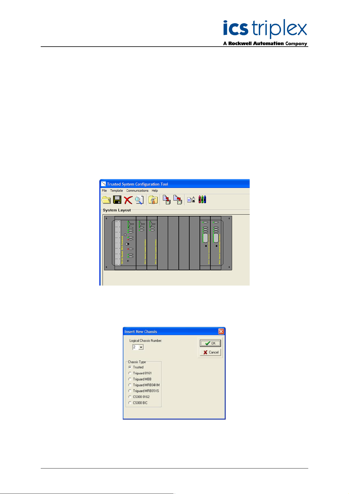
Figure 7 Trusted™ Processor Chassis with Expander Interface
The Triguard chassis are attached to the Expander Interface as if they were Trusted™ expander
chassis, but the various chassis options for Triguard and CS300 are provided on the ‘Insert New
Chassis’ dialog. Right-click on the grey background of the configurator window to insert a new chassis.
Figure 8 Insert New Chassis
Issue 2 Feb 10 PD-8161 12
Page 13
Trusted™ Bridge Module 8161
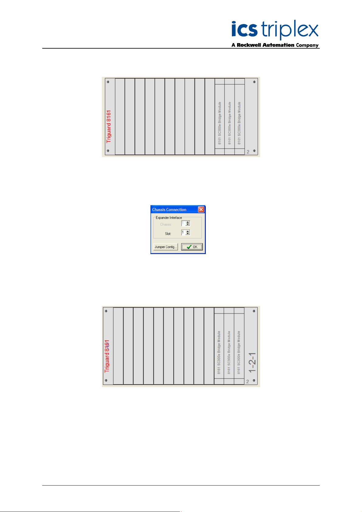
The first chassis to be created is a 8161. This includes the bridge modules in place of the Triguard
processors. Choose type Triguard 8161 and select a logical chassis number. This chassis number will
define the switch configuration described in section 2.3.
Figure 9 Triguard main chassis
The chassis should then be allocated to the Trusted™ Expander Interface module. Left-click on the left
or right end of the Triguard 8161 chassis to open the Chassis Connection dialog. Select the slot
number of the left-hand Expander Interface module.
Figure 10 Chassis Connection
On closing this dialog, the Triguard 8161 chassis should have a blue flash symbol on the left. The right
hand side shows the chassis address as:
< Trusted™ expander Interface slot> - <Expander socket number> - <Triguard chassis number>
Figure 11 Connected Chassis
Left-click on the left or right end of the 8161 chassis to open the Chassis Connection dialog again. The
‘Jumper Config’ button now demonstrates how to set the Triguard backplane jumpers.
Issue 2 Feb 10 PD-8161 13
Page 14

Trusted™ Bridge Module 8161
Figure 12 Jumper Setting
This chassis then links into the extension chassis MBB and MRB04XM. MBB is a local extension
chassis linked to the main chassis by ribbon cables. MRB04XM is also a local chassis but it provides
remote connection via fibre optic cables to slave chassis MRB04XS.
To add an MBB or MRB04XM chassis, right click again on the background and select the chassis type.
The jumper settings on these chassis should not be changed from their old configuration in the
Triguard system. Select the 8161 chassis to which the new chassis should be connected (Parent 8161
Chassis Number; the list will only show the chassis that exist already), and enter the chassis number
as configured on the address jumpers on the chassis (Triguard Chassis Number). Closing this window
and left-clicking on the chassis ends will show the Jumper Config button, which will confirm the switch
settings that have been selected. For the MRB04XM chassis, the two DIP switch settings are also
displayed.
Figure 13 MBB and MRB04XM Chassis Addressing
The chassis will now show its address on the right end as:
< Trusted™ expander Interface slot> - <Expander socket number> - <Triguard chassis number>
e.g. 1-2-2 in the above example.
To add an MRB04XS chassis (as an extension of an MRB04XM chassis you have already entered),
follow the previous chassis insertion procedure and choose an MRB04XS chassis. Check the four
address settings, which will have been allocated to the next available number automatically:
Parent 8161 Chassis Number Address of 8161 chassis on Trusted™ expander
Triguard Chassis Number Chassis address jumper setting on MRB04XS
Master Logical Chassis Number Chassis address jumper setting on MRB04XM
Slave Link Number MRB04XS connection to MRB04XM (1,2,3,4)
The Jumper Config button will be available on reopening the Chassis Configuration as above. The
chassis will now show its address on the right hand end as:
Issue 2 Feb 10 PD-8161 14
Page 15

Trusted™ Bridge Module 8161
< Trusted™ expander Interface slot> - <Expander socket number> - <Triguard chassis number> <Master logical chassis number> - <Slave link number>
e.g. 1-2-2-3-1 in the above example, if the system consists of a 8161 chassis, an MRB04XM chassis
nd an MRB04XS chassis.
a
Having added all the chassis in the system, the next step is to insert modules. For each module, rightclick on the appropriate chassis slot. Select the module from the list.
Figure 14 Triguard Modules
On left-clicking the new module, the module options are displayed.
Figure 15 Module Options
For output modules, select the output action on failure (Fallback Mode); either to set all outputs to
zero/de-energised or to remain at their last state.
For all modules, select the action on slice failure, either to shut down when only one slice is working (32-0) or to continue running on one slice (3-2-1).
To enable hot-repair (on-line replacement), check ‘Hot Repair Partner’. This will enable replacement
with the module in the slot to the right of this module. There is no need to check the box in the righthand module.
To allow the system to run with a module absent, check ‘Simulate’.
Ensure that the options selected are as configured in the original application.
Issue 2 Feb 10 PD-8161 15
Page 16

Trusted™ Bridge Module 8161
3.2 Board Definitions
There are no restrictions in the order of the boards set out in the connection table except in cases
where TM117-DMX (64-Channel De-Multiplexed Driver) termination cards are configured in the
system. These have to be defined before any SC300E I/O modules are specified. The DMX cards are
driven from the Trusted™ serial communications module.
It is also general convention to specify the Trusted™ main processor at the head of the connection
table.
In a true hybrid system including Trusted™ I/O modules, conventions for entering the various board
definitions have to be referred to in the associated Product Description.
Issue 2 Feb 10 PD-8161 16
Page 17

Trusted™ Bridge Module 8161
3.2.1 Module – 8161 (Bridge Module)
DESCRIPTION
his definition provides module status for a Logical Triguard 8161 primary chassis expansion interface
T
module.
The logical module accounts for the 3 physical modules FCR-A, FCR-B and FCR-C.
OEM PARAMETERS:
OEM parameter Valid numbers Description
CHASSIS 2-29 Logical chassis number allocated to the primary
Triguard chassis in which the 8161 modules
are placed.
SLOT 15 Logical slot within the Primary Triguard chassis
by which the 8000 system identifies the 8161
module. This cannot be configured.
PHYSICAL MODULE:
RACK 1: [STATUS] - 6 BOOL Inputs
Variable 1: TRUE = Logical module responding
Variable 2: TRUE = FCR-A faulted or not responding
Variable 3: TRUE = FCR-B faulted or not responding
Variable 4: TRUE = FCR-C faulted or not responding
Variable 5: TRUE = Power supply 1 faulted
Variable 6: TRUE = Power supply 2 faulted
RACK 2: [INFO] - 12 ANALOGUE Inputs
Word 1: FCR-A fault code (see note 1)
Word 2: FCR-B fault code (see note 1)
Word 3: FCR-C fault code (see note 1)
Word 4: FCR-A hot-link error count
Word 5: FCR-B hot-link error count
Word 6: FCR-C hot-link error count
Word 7: FCR-A IML own-link error count
Word 8: FCR-A IML down-link error count
Word 9: FCR-A IML up-link error count
Word 10: FCR-B IML own-link error count
Word 11: FCR-B IML down-link error count
Word 12: FCR-B IML up-link error count
Word 13: FCR-C IML own-link error count
Word 14: FCR-C IML down-link error count
Word 15: FCR-C IML up-link error count
[Note 1 - Fault Codes]
0 : No fault
1 : Local backplane fault
2 : Local expansion bus fault
3 : Common fault (applies to both local backplane and expansion busses)
Issue 2 Feb 10 PD-8161 17
Page 18

Trusted™ Bridge Module 8161
3.2.2 Module – MBB (Bus interface Module)
DESCRIPTION
his definition provides module status for a logical Triguard MBB local chassis expansion module.
T
The logical module accounts for the 3 physical modules FCR-A, FCR-B and FCR-C.
OEM PARAMETERS:
OEM parameter Valid numbers Description
CHASSIS 2-29 Logical chassis number allocated to the local
secondary Triguard chassis in which the MBB
modules are placed.
SLOT 15 Logical slot within the local secondary Triguard
chassis by which the 8000 system identifies the
MBB module. This cannot be configured.
PHYSICAL MODULE:
RACK 1: [STATUS] - 10 BOOL Inputs
Variable 1: FALSE (Not used)
Variable 2: TRUE = FCR-A faulted
Variable 3: TRUE = FCR-B faulted
Variable 4: TRUE = FCR-C faulted
Note: The status of MBB FCR's can only be determined by the discrepancy status of accesses
performed to I/O modules within the chassis of the MBB. If no such modules exist or if no MBB
FCR's are fitted then no faults can be reported.
Issue 2 Feb 10 PD-8161 18
Page 19

Trusted™ Bridge Module 8161
3.2.3 Module – mai32lad (0-5V; analogue input Module)
DESCRIPTION
his definition will open a single MAI32LAD.
T
OEM PARAMETERS
OEM parameter Valid numbers Description
CHASSIS 2-29 Logical chassis and slot number where the
SLOT 1-10 MAI32LAD is located.
PHYSICAL MODULE:
RACK 1: (AI)
32 INTEGER inputs
RACK 2: (DIAG)
3 INTEGER inputs
Word 1 Health status bits, 0=healthy 1=fault
bit 0-2 Microcontroller watchdog (bit 0=A, bit 1=B, bit2=C)
bit 3-5 MP watchdog (bit 0=A, bit 1=B, bit2=C)
bit 6-8 Microcontroller slice health (bit 0=A, bit 1=B, bit2=C)
bit 9-11 Combined slice health (bit 0=A, bit 1=B, bit2=C)
bit 12 Power Fail
bit 13-15 not used
Word 2 Diagnostic bits
bit 0 Slice A
=1 slice is not responding or there is an error
=0 slice is responding
bit 1 Slice B
=1 slice is not responding or there is an error
=0 slice is responding
bit 2 Slice C
=1 slice is not responding or there is an error
=0 slice is responding
bit 3 Module offline or missing
=1 offline or missing
=0 online
bit 4 Single slot hot repair
=1 in progress
=0 not in progress
bit 5 Discrepancy errors
=1 faults detected
=0 no faults detected
bit 6 LFD faults
=1 faults detected
=0 no faults detected
Word 3 Slot number of active module
RACK 3: (FAULTS)
4 INTEGER inputs
Word 1 Discrepancy errors, channels 1-16 (bit 0 = channel 1)
Word 2 Discrepancy errors, channels 17-32 (bit 0 = channel 17)
Word 3 LFD errors, channels 1-16 (bit 0 = channel 1)
Word 4 LFD errors, channels 17-32 (bit 0 = channel 17)
Issue 2 Feb 10 PD-8161 19
Page 20

Trusted™ Bridge Module 8161
3.2.4 Module – mai32mad (0-10V; analogue input Module)
DESCRIPTION
his definition will open a single MAI32MAD.
T
OEM PARAMETERS
OEM parameter Valid numbers Description
CHASSIS 2-29 Logical chassis and slot number where the
SLOT 1-10 MAI32MAD is located.
PHYSICAL MODULE:
RACK 1: (AI)
32 INTEGER inputs
RACK 2: (DIAG)
3 INTEGER inputs
Word 1 Health status bits, 0=healthy 1=fault
bit 0-2 Microcontroller watchdog (bit 0=A, bit 1=B, bit2=C)
bit 3-5 MP watchdog (bit 0=A, bit 1=B, bit2=C)
bit 6-8 Microcontroller slice health (bit 0=A, bit 1=B, bit2=C)
bit 9-11 Combined slice health (bit 0=A, bit 1=B, bit2=C)
bit 12 Power Fail
bit 13-15 not used
Word 2 Diagnostic bits
bit 0 Slice A
=1 slice is not responding or there is an error
=0 slice is responding
bit 1 Slice B
=1 slice is not responding or there is an error
=0 slice is responding
bit 2 Slice C
=1 slice is not responding or there is an error
=0 slice is responding
bit 3 Module offline or missing
=1 offline or missing
=0 online
bit 4 Single slot hot repair
=1 in progress
=0 not in progress
bit 5 Discrepancy errors
=1 faults detected
=0 no faults detected
bit 6 LFD faults
=1 faults detected
=0 no faults detected
Word 3 Slot number of active module
RACK 3: (FAULTS)
4 INTEGER inputs
Word 1 Discrepancy errors, channels 1-16 (bit 0 = channel 1)
Word 2 Discrepancy errors, channels 17-32 (bit 0 = channel 17)
Word 3 LFD errors, channels 1-16 (bit 0 = channel 1)
Word 4 LFD errors, channels 17-32 (bit 0 = channel 17)
Issue 2 Feb 10 PD-8161 20
Page 21

Trusted™ Bridge Module 8161
3.2.5 Module – mai32nad (0-20Ma; analogue input Module)
DESCRIPTION
his definition will open a single MAI32NAD.
T
OEM PARAMETERS
OEM parameter Valid numbers Description
CHASSIS 2-29 Logical chassis and slot number where the
SLOT 1-10 MAI32NAD is located.
PHYSICAL MODULE:
RACK 1: (AI)
32 INTEGER inputs
RACK 2: (DIAG)
3 INTEGER inputs
Word 1 Health status bits, 0=healthy 1=fault
bit 0-2 Microcontroller watchdog (bit 0=A, bit 1=B, bit2=C)
bit 3-5 MP watchdog (bit 0=A, bit 1=B, bit2=C)
bit 6-8 Microcontroller slice health (bit 0=A, bit 1=B, bit2=C)
bit 9-11 Combined slice health (bit 0=A, bit 1=B, bit2=C)
bit 12 Power Fail
bit 13-15 not used
Word 2 Diagnostic bits
bit 0 Slice A
=1 slice is not responding or there is an error
=0 slice is responding
bit 1 Slice B
=1 slice is not responding or there is an error
=0 slice is responding
bit 2 Slice C
=1 slice is not responding or there is an error
=0 slice is responding
bit 3 Module offline or missing
=1 offline or missing
=0 online
bit 4 Single slot hot repair
=1 in progress
=0 not in progress
bit 5 Discrepancy errors
=1 faults detected
=0 no faults detected
bit 6 LFD faults
=1 faults detected
=0 no faults detected
Word 3 Slot number of active module
RACK 3: (FAULTS)
4 INTEGER inputs
Word 1 Discrepancy errors, channels 1-16 (bit 0 = channel 1)
Word 2 Discrepancy errors, channels 17-32 (bit 0 = channel 17)
Word 3 LFD errors, channels 1-16 (bit 0 = channel 1)
Word 4 LFD errors, channels 17-32 (bit 0 = channel 17)
Issue 2 Feb 10 PD-8161 21
Page 22

Trusted™ Bridge Module 8161
3.2.6 Module – mai32pad (0-40Ma; analogue input Module)
DESCRIPTION
his definition will open a single MAI32PAD.
T
OEM PARAMETERS
OEM parameter Valid numbers Description
CHASSIS 2-29 Logical chassis and slot number where the
SLOT 1-10 MAI32PAD is located.
PHYSICAL MODULE:
RACK 1: (AI)
32 INTEGER inputs
RACK 2: (DIAG)
3 INTEGER inputs
Word 1 Health status bits, 0=healthy 1=fault
bit 0-2 Microcontroller watchdog (bit 0=A, bit 1=B, bit2=C)
bit 3-5 MP watchdog (bit 0=A, bit 1=B, bit2=C)
bit 6-8 Microcontroller slice health (bit 0=A, bit 1=B, bit2=C)
bit 9-11 Combined slice health (bit 0=A, bit 1=B, bit2=C)
bit 12 Power Fail
bit 13-15 not used
Word 2 Diagnostic bits
bit 0 Slice A
=1 slice is not responding or there is an error
=0 slice is responding
bit 1 Slice B
=1 slice is not responding or there is an error
=0 slice is responding
bit 2 Slice C
=1 slice is not responding or there is an error
=0 slice is responding
bit 3 Module offline or missing
=1 offline or missing
=0 online
bit 4 Single slot hot repair
=1 in progress
=0 not in progress
bit 5 Discrepancy errors
=1 faults detected
=0 no faults detected
bit 6 LFD faults
=1 faults detected
=0 no faults detected
Word 3 Slot number of active module
RACK 3: (FAULTS)
4 INTEGER inputs
Word 1 Discrepancy errors, channels 1-16 (bit 0 = channel 1)
Word 2 Discrepancy errors, channels 17-32 (bit 0 = channel 17)
Word 3 LFD errors, channels 1-16 (bit 0 = channel 1)
Word 4 LFD errors, channels 17-32 (bit 0 = channel 17)
Issue 2 Feb 10 PD-8161 22
Page 23

Trusted™ Bridge Module 8161
3.2.7 Module – mao04nnd (0-22Ma; analogue output Module)
DESCRIPTION
his definition will open a single MAO04NND.
T
OEM PARAMETERS
OEM parameter Valid numbers Description
CHASSIS 2-29 Logical chassis and slot number where the
SLOT 1-10 MAO04NND is located.
PHYSICAL MODULE:
RACK 1: (AO)
4 INTEGER outputs
RACK 2: (DIAG)
4 INTEGER inputs
Word 1 Health status bits, 0=healthy 1=fault
bit 0-2 Microcontroller watchdog (bit 0=A, bit 1=B, bit2=C)
bit 3-5 MP watchdog (bit 0=A, bit 1=B, bit2=C)
bit 6-8 Microcontroller slice health (bit 0=A, bit 1=B, bit2=C)
bit 9-11 Combined slice health (bit 0=A, bit 1=B, bit2=C)
bit 12 Power Fail
bit 13-15 not used
Word 2 Diagnostic bits
bit 0 Slice A
=1 slice is not responding or there is an error
=0 slice is responding
bit 1 Slice B
=1 slice is not responding or there is an error
=0 slice is responding
bit 2 Slice C
=1 slice is not responding or there is an error
=0 slice is responding
bit 3 Module offline or missing
=1 offline or missing
=0 online
bit 4 Single slot hot repair
=1 in progress
=0 not in progress
bit 5 Discrepancy errors
=1 faults detected
=0 no faults detected
bit 6 LFD faults
=1 faults detected
=0 no faults detected
Word 3 Slot number of active module
Issue 2 Feb 10 PD-8161 23
Page 24

Trusted™ Bridge Module 8161
Word 4 Fault flags, 0=healthy 1=fault
bit 0-2 Logic supply power fail fault (ABC, bit0=A, bit2=C)
bit 3-5 Reserved
bit 6 Field power fail fault
bit 7 Output discrepancy error
bit 8-15 Reserved
RACK 3: (FAULTS)
1 INTEGER input
Word 1 LFD errors, channels 1-4 (bit 0 = channel 1)
Issue 2 Feb 10 PD-8161 24
Page 25

Trusted™ Bridge Module 8161
3.2.8 Module – mdi32bis (24v; digital input Module)
DESCRIPTION
his definition will open a single MDI32BIS.
T
OEM PARAMETERS
OEM parameter Valid numbers Description
CHASSIS 2-29 Logical chassis and slot number where the
SLOT 1-10 MDI32BIS is located.
PHYSICAL MODULE:
RACK 1: (DI)
32 BOOLEAN inputs
RACK 2: (DIAG)
3 INTEGER inputs
Word 1 Health status bits, 0=healthy 1=fault
bit 0-2 Microcontroller watchdog (bit 0=A, bit 1=B, bit2=C)
bit 3-5 MP watchdog (bit 0=A, bit 1=B, bit2=C)
bit 6-8 Microcontroller slice health (bit 0=A, bit 1=B, bit2=C)
bit 9-11 Combined slice health (bit 0=A, bit 1=B, bit2=C)
bit 12 Power Fail
bit 13-15 not used
Word 2 Diagnostic bits
bit 0 Slice A
=1 slice is not responding or there is an error
=0 slice is responding
bit 1 Slice B
=1 slice is not responding or there is an error
=0 slice is responding
bit 2 Slice C
=1 slice is not responding or there is an error
=0 slice is responding
bit 3 Module offline or missing
=1 offline or missing
=0 online
bit 4 Single slot hot repair
=1 in progress
=0 not in progress
bit 5 Discrepancy errors
=1 faults detected
=0 no faults detected
bit 6 LFD faults
=1 faults detected
=0 no faults detected
Word 3 Slot number of active module
RACK 3: (FAULTS)
4 INTEGER inputs
Word 1 Discrepancy errors, channels 1-16 (bit 0 = channel 1)
Word 2 Discrepancy errors, channels 17-32 (bit 0 = channel 17)
Word 3 LFD errors, channels 1-16 (bit 0 = channel 1)
Word 4 LFD errors, channels 17-32 (bit 0 = channel 17)
Issue 2 Feb 10 PD-8161 25
Page 26

Trusted™ Bridge Module 8161
3.2.9 Module – mdi32fis (120v; digital input Module)
DESCRIPTION
his definition will open a single MDI32FIS.
T
OEM PARAMETERS
OEM parameter Valid numbers Description
CHASSIS 2-29 Logical chassis and slot number where the
SLOT 1-10 MDI32FIS is located.
PHYSICAL MODULE:
RACK 1: (DI)
32 BOOLEAN inputs
RACK 2: (DIAG)
3 INTEGER inputs
Word 1 Health status bits, 0=healthy 1=fault
bit 0-2 Microcontroller watchdog (bit 0=A, bit 1=B, bit2=C)
bit 3-5 MP watchdog (bit 0=A, bit 1=B, bit2=C)
bit 6-8 Microcontroller slice health (bit 0=A, bit 1=B, bit2=C)
bit 9-11 Combined slice health (bit 0=A, bit 1=B, bit2=C)
bit 12 Power Fail
bit 13-15 not used
Word 2 Diagnostic bits
bit 0 Slice A
=1 slice is not responding or there is an error
=0 slice is responding
bit 1 Slice B
=1 slice is not responding or there is an error
=0 slice is responding
bit 2 Slice C
=1 slice is not responding or there is an error
=0 slice is responding
bit 3 Module offline or missing
=1 offline or missing
=0 online
bit 4 Single slot hot repair
=1 in progress
=0 not in progress
bit 5 Discrepancy errors
=1 faults detected
=0 no faults detected
bit 6 LFD faults
=1 faults detected
=0 no faults detected
Word 3 Slot number of active module
RACK 3: (FAULTS)
4 INTEGER inputs
Word 1 Discrepancy errors, channels 1-16 (bit 0 = channel 1)
Word 2 Discrepancy errors, channels 17-32 (bit 0 = channel 17)
Word 3 LFD errors, channels 1-16 (bit 0 = channel 1)
Word 4 LFD errors, channels 17-32 (bit 0 = channel 17)
Issue 2 Feb 10 PD-8161 26
Page 27

Trusted™ Bridge Module 8161
3.2.10 Module – mdi32gis (48v; digital input Module)
DESCRIPTION
his definition will open a single MDI32GIS.
T
OEM PARAMETERS
OEM parameter Valid numbers Description
CHASSIS 2-29 Logical chassis and slot number where the
SLOT 1-10 MDI32GIS is located.
PHYSICAL MODULE:
RACK 1: (DI)
32 BOOLEAN inputs
RACK 2: (DIAG)
3 INTEGER inputs
Word 1 Health status bits, 0=healthy 1=fault
bit 0-2 Microcontroller watchdog (bit 0=A, bit 1=B, bit2=C)
bit 3-5 MP watchdog (bit 0=A, bit 1=B, bit2=C)
bit 6-8 Microcontroller slice health (bit 0=A, bit 1=B, bit2=C)
bit 9-11 Combined slice health (bit 0=A, bit 1=B, bit2=C)
bit 12 Power Fail
bit 13-15 not used
Word 2 Diagnostic bits
bit 0 Slice A
=1 slice is not responding or there is an error
=0 slice is responding
bit 1 Slice B
=1 slice is not responding or there is an error
=0 slice is responding
bit 2 Slice C
=1 slice is not responding or there is an error
=0 slice is responding
bit 3 Module offline or missing
=1 offline or missing
=0 online
bit 4 Single slot hot repair
=1 in progress
=0 not in progress
bit 5 Discrepancy errors
=1 faults detected
=0 no faults detected
bit 6 LFD faults
=1 faults detected
=0 no faults detected
Word 3 Slot number of active module
RACK 3: (FAULTS)
4 INTEGER inputs
Word 1 Discrepancy errors, channels 1-16 (bit 0 = channel 1)
Word 2 Discrepancy errors, channels 17-32 (bit 0 = channel 17)
Word 3 LFD errors, channels 1-16 (bit 0 = channel 1)
Word 4 LFD errors, channels 17-32 (bit 0 = channel 17)
Issue 2 Feb 10 PD-8161 27
Page 28

Trusted™ Bridge Module 8161
3.2.11 Module – mdi64bns (24v simplex; digital input Module)
DESCRIPTION
his definition will open a single MDI64BNS.
T
OEM PARAMETERS
OEM parameter Valid numbers Description
CHASSIS 2-29 Logical chassis and slot number where the
SLOT 1-10 MDI64BNS is located.
PHYSICAL MODULE:
RACK 1: (DI)
64 BOOLEAN inputs
RACK 2: (DIAG)
3 INTEGER inputs
Word 1 Health status bits, 0=healthy 1=fault
bit 0-2 Microcontroller watchdog (bit 0=A, bit 1=B, bit2=C)
bit 3-5 MP watchdog (bit 0=A, bit 1=B, bit2=C)
bit 6-8 Microcontroller slice health (bit 0=A, bit 1=B, bit2=C)
bit 9-11 Combined slice health (bit 0=A, bit 1=B, bit2=C)
bit 12 Power Fail
bit 13-15 not used
Word 2 Diagnostic bits
bit 0 Slice A
=1 slice is not responding or there is an error
=0 slice is responding
bit 1 Slice B
=1 slice is not responding or there is an error
=0 slice is responding
bit 2 Slice C
=1 slice is not responding or there is an error
=0 slice is responding
bit 3 Module offline or missing
=1 offline or missing
=0 online
bit 4 Single slot hot repair
=1 in progress
=0 not in progress
bit 5 Discrepancy errors
=1 faults detected
=0 no faults detected
bit 6 LFD faults
=1 faults detected
=0 no faults detected
Word 3 Slot number of active module
Issue 2 Feb 10 PD-8161 28
Page 29

Trusted™ Bridge Module 8161
RACK 3: (FAULTS)
8 INTEGER inputs
Word 1 Discrepancy errors, channels 1-16 (bit 0 = channel 1)
Word 2 Discrepancy errors, channels 17-32 (bit 0 = channel 17)
Word 3 Discrepancy errors, channels 33-48 (bit 0 = channel 33)
Word 4 Discrepancy errors, channels 49-64 (bit 0 = channel 49)
Word 5 LFD errors, channels 1-16 (bit 0 = channel 1)
Word 6 LFD errors, channels 17-32 (bit 0 = channel 17)
Word 7 LFD errors, channels 33-48 (bit 0 = channel 33)
Word 8 LFD errors, channels 49-64 (bit 0 = channel 49)
Issue 2 Feb 10 PD-8161 29
Page 30

Trusted™ Bridge Module 8161
3.2.12 Module – mdo16fns (120v; digital output Module)
DESCRIPTION
his definition will open a single MDO16FNS.
T
OEM PARAMETERS
OEM parameter Valid numbers Description
CHASSIS 2-29 Logical chassis and slot number where the
SLOT 1-10 MDO16FNS is located.
PHYSICAL MODULE:
RACK 1: (DO)
16 BOOLEAN outputs
RACK 2: (DIAG)
4 INTEGER inputs
Word 1 Health status bits, 0=healthy 1=fault
bit 0-2 Microcontroller watchdog (bit 0=A, bit 1=B, bit2=C)
bit 3-5 MP watchdog (bit 0=A, bit 1=B, bit2=C)
bit 6-8 Microcontroller slice health (bit 0=A, bit 1=B, bit2=C)
bit 9-11 Combined slice health (bit 0=A, bit 1=B, bit2=C)
bit 12 Power Fail
bit 13-15 not used
Word 2 Diagnostic bits
bit 0 Slice A
=1 slice is not responding or there is an error
=0 slice is responding
bit 1 Slice B
=1 slice is not responding or there is an error
=0 slice is responding
bit 2 Slice C
=1 slice is not responding or there is an error
=0 slice is responding
bit 3 Module offline or missing
=1 offline or missing
=0 online
bit 4 Single slot hot repair
=1 in progress
=0 not in progress
bit 5 Discrepancy errors
=1 faults detected
=0 no faults detected
bit 6 LFD faults
=1 faults detected
=0 no faults detected
Word 3 Slot number of active module
Issue 2 Feb 10 PD-8161 30
Page 31

Trusted™ Bridge Module 8161
Word 4 Fault flags, 0=healthy 1=fault
bit 0-2 Logic supply power fail fault (ABC, bit0=A, bit2=C)
bit 3-5 Field supply power fail fault (ABC)
bit 6 Bias supply 1 power fail fault
bit 7 Bias supply 2 power fail fault
bit 8 Logic supply power fail fault
bit 9-10 Reserved
bit 11-13 Drive supply power fail fault (ABC)
bit 14 Field supply power fail fault
bit 15 Over temperature fault
RACK 3: (FAULTS)
1 INTEGER inputs
Word 1 LFD errors, channels 1-16 (bit 0 = channel 1)
Issue 2 Feb 10 PD-8161 31
Page 32

Trusted™ Bridge Module 8161
3.2.13 Module – mdo16gns (48v; digital output Module)
DESCRIPTION
his definition will open a single MDO16GNS.
T
OEM PARAMETERS
OEM parameter Valid numbers Description
CHASSIS 2-29 Logical chassis and slot number where the
SLOT 1-10 MDO16GNS is located.
PHYSICAL MODULE:
RACK 1: (DO)
16 BOOLEAN outputs
RACK 2: (DIAG)
4 INTEGER inputs
Word 1 Health status bits, 0=healthy 1=fault
bit 0-2 Microcontroller watchdog (bit 0=A, bit 1=B, bit2=C)
bit 3-5 MP watchdog (bit 0=A, bit 1=B, bit2=C)
bit 6-8 Microcontroller slice health (bit 0=A, bit 1=B, bit2=C)
bit 9-11 Combined slice health (bit 0=A, bit 1=B, bit2=C)
bit 12 Power Fail
bit 13-15 not used
Word 2 Diagnostic bits
bit 0 Slice A
=1 slice is not responding or there is an error
=0 slice is responding
bit 1 Slice B
=1 slice is not responding or there is an error
=0 slice is responding
bit 2 Slice C
=1 slice is not responding or there is an error
=0 slice is responding
bit 3 Module offline or missing
=1 offline or missing
=0 online
bit 4 Single slot hot repair
=1 in progress
=0 not in progress
bit 5 Discrepancy errors
=1 faults detected
=0 no faults detected
bit 6 LFD faults
=1 faults detected
=0 no faults detected
Word 3 Slot number of active module
Issue 2 Feb 10 PD-8161 32
Page 33

Trusted™ Bridge Module 8161
Word 4 Fault flags, 0=healthy 1=fault
bit 0-2 Logic supply power fail fault (ABC, bit0=A, bit2=C)
bit 3-5 Field supply power fail fault (ABC)
bit 6 Bias supply 1 power fail fault
bit 7 Bias supply 2 power fail fault
bit 8 Logic supply power fail fault
bit 9-10 Reserved
bit 11-13 Drive supply power fail fault (ABC)
bit 14 Field supply power fail fault
bit 15 Over temperature fault
RACK 3: (FAULTS)
1 INTEGER inputs
Word 1 LFD errors, channels 1-16 (bit 0 = channel 1)
Issue 2 Feb 10 PD-8161 33
Page 34

Trusted™ Bridge Module 8161
3.2.14 Module – mdo32bns (24v; digital output Module)
DESCRIPTION
his definition will open a single MDO32BNS.
T
OEM PARAMETERS
OEM parameter Valid numbers Description
CHASSIS 2-29 Logical chassis and slot number where the
SLOT 1-10 MDO32BNS is located.
PHYSICAL MODULE:
RACK 1: (DO)
32 BOOLEAN outputs
RACK 2: (DIAG)
4 INTEGER inputs
Word 1 Health status bits, 0=healthy 1=fault
bit 0-2 Microcontroller watchdog (bit 0=A, bit 1=B, bit2=C)
bit 3-5 MP watchdog (bit 0=A, bit 1=B, bit2=C)
bit 6-8 Microcontroller slice health (bit 0=A, bit 1=B, bit2=C)
bit 9-11 Combined slice health (bit 0=A, bit 1=B, bit2=C)
bit 12 Power Fail
bit 13-15 not used
Word 2 Diagnostic bits
bit 0 Slice A
=1 slice is not responding or there is an error
=0 slice is responding
bit 1 Slice B
=1 slice is not responding or there is an error
=0 slice is responding
bit 2 Slice C
=1 slice is not responding or there is an error
=0 slice is responding
bit 3 Module offline or missing
=1 offline or missing
=0 online
bit 4 Single slot hot repair
=1 in progress
=0 not in progress
bit 5 Discrepancy errors
=1 faults detected
=0 no faults detected
bit 6 LFD faults
=1 faults detected
=0 no faults detected
Word 3 Slot number of active module
Issue 2 Feb 10 PD-8161 34
Page 35

Trusted™ Bridge Module 8161
Word 4 Fault flags, 0=healthy 1=fault
bit 0-2 Logic supply power fail fault (ABC, bit0=A, bit2=C)
bit 3-5 Field supply power fail fault (ABC)
bit 6 Bias supply 1 power fail fault
bit 7 Bias supply 2 power fail fault
bit 8 Logic supply power fail fault
bit 9-10 Reserved
bit 11-13 Drive supply power fail fault (ABC)
bit 14 Field supply power fail fault
bit 15 Over temperature fault
RACK 3: (FAULTS)
2 INTEGER inputs
Word 1 LFD errors, channels 1-16 (bit 0 = channel 1)
Word 2 LFD errors, channels 17-32 (bit 0 = channel 17)
Issue 2 Feb 10 PD-8161 35
Page 36

Trusted™ Bridge Module 8161
3.2.15 Module – mhb44ind (Pulse-in/analogue output Module)
DESCRIPTION
his definition will open a single MHB44IND.
T
OEM PARAMETERS
OEM parameter Valid numbers Description
CHASSIS 2-29 Logical chassis and slot number where the
SLOT 1-10 MHB44IND is located.
PHYSICAL MODULE:
RACK 1: (PI)
4 INTEGER inputs
RACK 2: (AO)
4 INTEGER outputs
RACK 3: (DIAG)
4 INTEGER inputs
Word 1 Health status bits, 0=healthy 1=fault
bit 0-2 Microcontroller watchdog (bit 0=A, bit 1=B, bit2=C)
bit 3-5 MP watchdog (bit 0=A, bit 1=B, bit2=C)
bit 6-8 Microcontroller slice health (bit 0=A, bit 1=B, bit2=C)
bit 9-11 Combined slice health (bit 0=A, bit 1=B, bit2=C)
bit 12 Power Fail
bit 13-15 not used
Word 2 Diagnostic bits
bit 0 Slice A
=1 slice is not responding or there is an error
=0 slice is responding
bit 1 Slice B
=1 slice is not responding or there is an error
=0 slice is responding
bit 2 Slice C
=1 slice is not responding or there is an error
=0 slice is responding
bit 3 Module offline or missing
=1 offline or missing
=0 online
bit 4 Single slot hot repair
=1 in progress
=0 not in progress
bit 5 Discrepancy errors
=1 faults detected
=0 no faults detected
bit 6 LFD faults
=1 faults detected
=0 no faults detected
Word 3 Slot number of active module
Issue 2 Feb 10 PD-8161 36
Page 37

Trusted™ Bridge Module 8161
Word 4 Fault flags, 0=healthy 1=fault
bit 0-2 Logic supply power fail fault (ABC, bit0=A, bit2=C)
bit 3-5 Reserved
bit 6 Field power fail fault
bit 7 Output discrepancy error
bit 8-15 Reserved
RACK 4: (FAULTS)
3 INTEGER inputs
Word 1 Discrepancy errors
bits 0-3 PI channels 1-4 (bit 0 = channel 1)
Word 2 LFD errors
bits 0-3 PI channels 1-4 (bit 0 = channel 1)
bits 4-7 AO channels 1-4 (bit 4 = channel 1)
Issue 2 Feb 10 PD-8161 37
Page 38

Trusted™ Bridge Module 8161
3.2.16 Module – mrb01xs (remote slave Module)
DESCRIPTION
his definition provides module status for a logical Triguard MRB01XS remote slave chassis expansion
T
module.
The logical module accounts for the 3 physical modules FCR-A, FCR-B and FCR-C.
OEM PARAMETERS:
OEM parameter Valid numbers Description
CHASSIS 2-29 Logical chassis number allocated to the remote
slave Triguard chassis in which the MRB01XS
modules are placed.
SLOT 15 Logical slot within the remote slave Triguard
chassis by which the 8000 system identifies the
MRB01XS module. This cannot be configured.
PHYSICAL MODULE:
RACK 1: [STATUS] - 10 BOOL Inputs
Variable 1: FALSE (Not used)
Variable 2: TRUE = FCR-A faulted (see note 1)
Variable 3: TRUE = FCR-B faulted (see note 1)
Variable 4: TRUE = FCR-C faulted (see note 1)
[Note 1]
The status of MRB01XS FCR's can only be determined by the discrepancy status of accesses
performed to I/O modules within the chassis of the MRB01XS. If no such modules exist or if no
MRB01XS FCR's are fitted then no faults can be reported.
Issue 2 Feb 10 PD-8161 38
Page 39

Trusted™ Bridge Module 8161
3.2.17 Module – mrb04xm (remote master Module)
DESCRIPTION
his definition provides module status for a logical Triguard MRB04XM remote master chassis
T
expansion interface module.
The logical module accounts for the 3 physical modules FCR-A, FCR-B and FCR-C.
OEM PARAMETERS:
OEM parameter Valid numbers Description
CHASSIS 2-29 Logical chassis number allocated to the
secondary Triguard chassis in which the
MRB04XM modules are placed.
SLOT 15 Logical slot within the secondary Triguard
chassis by which the 8000 system identifies the
MRB04XM module. This cannot be configured.
PHYSICAL MODULE:
RACK 1: [STATUS] - 4 BOOL Inputs
Variable 1: FALSE (not used)
Variable 2: TRUE = FCR-A faulted (see note 2)
Variable 3: TRUE = FCR-B faulted (see note 2)
Variable 4: TRUE = FCR-C faulted (see note 2)
RACK 2: [INFO] - 3 ANALOGUE Inputs
Word 1: FCR-A fault code (see note 1)
Word 2: FCR-B fault code (see note 1)
Word 3: FCR-C fault code (see note 1)
[Note 1 - Fault Codes]
0 : No Fault
1 : Local Backplane fault
2 : Remote Expansion fault
3 : Common fault (applies to both Local and Remote busses)
[Note 2 - Fault Detection]
The status of MBB FCR's can only be determined by the discrepancy status of accesses performed to
I/O modules within the chassis of the MRB04XM and to Remote Slave chassis connected to this
Remote Master. If no such modules exist or if no MRB04XM FCR's are fitted then no faults can be
reported.
Issue 2 Feb 10 PD-8161 39
Page 40

Trusted™ Bridge Module 8161
4. Operation
Figure 16 Front Panel Layout
Issue 2 Feb 10 PD-8161 40
Page 41

Trusted™ Bridge Module 8161
4.1 Front Panel Indicators and Controls
4.1.1 Tx & Rx Indicators
lashing amber LEDs indicate active transmit and receive communications on the Expander Bus.
F
4.1.2 Health Indicator
A steady green LED indicates a fault-free Bridge module; an extinguished LED indicates a fault.
4.1.3 On-Line Indicator and Switch
Raising and releasing the on/off-line switch momentarily takes the module off-line, which is mirrored by
the steady On/Off state of the amber On-Line LED. Repeating the action brings the module back online.
Prior to hot-swapping the module for repair, it should be taken off-line using this feature to ensure a
clean exit from the system. The replacement module is then placed on-line using the switch.
Issue 2 Feb 10 PD-8161 41
Page 42

Trusted™ Bridge Module 8161
5. Fault Finding and Maintenance
The Trusted™ TMR Processor provides fault monitoring, self test and diagnostics functions.
Fault Detection within a Trusted™ / SC300E system can be categorised into four regions -
Trusted™ TMR Processor and Expander Hardware
SC300E Bridge Hardware
SC300E I/O Hardware
User Application
Using current Trusted™ methods for detection of faults, the TMR Processor can monitor for failures up
to the Expander section. The TMR Processor is also able to separate Bridge hardware faults from
SC300E I/O module faults. The Triguard I/O modules carry out on-board diagnostic tests which are
relayed back to the TMR Processor via the Bridge module.
The user application can also be programmed to read error flags in the I/O module fault registers to
annunciate the detection of module faults. Second faults that leave the system unable to confirm
healthy operation will result in the TMR Processor stopping all communication with the 8161 bridge
modules, ensuring that critical outputs go to a safe state when the internal watchdogs time out.
Issue 2 Feb 10 PD-8161 42
Page 43

Trusted™ Bridge Module 8161
6. Specifications
Supply Voltage 5.4V DC ± 5%
Heat Dissipation 3W max
perating Temperature (convection cooling) 0°C to 60ºC (32°F to 140°F)
O
Storage Temperature -40°C to 100ºC (-40°F to 212°F)
Operating Humidity 5 to 95% RH, non-condensing
Vibration 10 to 500 Hz peak to peak 1g
Shock Operating:11ms, ½ sine wave 15g
Height: 400 mm (15.7 ins)
Width: 27 mm (1.1 ins)
Depth: 404 mm (15.9 ins)
Weight (approx) 900g (2.0 lbs.)
Issue 2 Feb 10 PD-8161 43
 Loading...