

Page 1
Installation Instructions
1
6
3
7
6
5
4
2
8
9
10
Original Instructions
SafeZone 3 Safety Laser Scanner Mounting
Catalog Numbers 442L-SZNMZCP, 442L-SZNCPMOD
8020211
Top ic Pa ge
About This Document 1
Safety Information 1
Device Overview 1
Install the System Plug 1
Connection Overview 2
Pin Assignment 2
Replace the Safety Laser Scanner 3
Replace the System Plug 3
About This Document
This document applies to the SafeZone™ 3 safety laser scanner and the associated
system plug with catalog numbers 442L-SZNMZCP and 442L-SZNCPMOD.
Safety Information
ATTENTION: Hazard due to lack of effectiveness of the
SafeZone 3 safety laser scanner. If noncompliant, it is possible
that the dangerous state of the machine may not be stopped
or not stopped in a timely manner.
Observe the safety information provided.
The safety laser scanner is not suitable for the following applications, among
others:
• Outdoors
• Underwater
• Explosive environments
For detailed information on the application and configuration of the SafeZone 3
safety laser scanner, refer to publication 442L-UM008
.
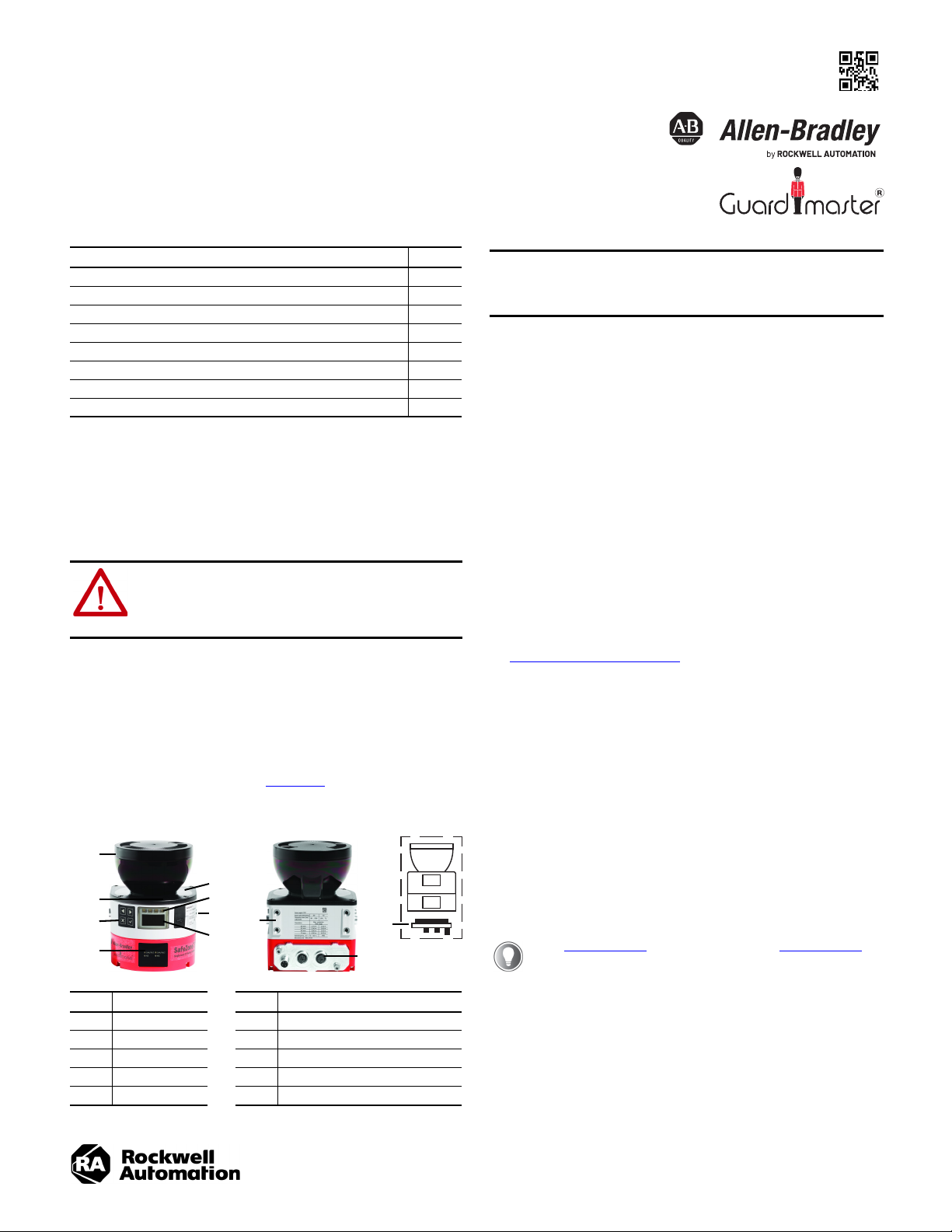
Device Overview
IMPORTANT
All changes/modifications to the SafeZone 3 safety
laser scanner and/or system plug that are described in
this document, must be performed only after the
removal of power to the devices.
Install the System Plug
The SafeZone 3 safety laser scanner and the system plug are sold separately
requiring the system plug to be installed on the SafeZone 3 safety laser scanner.
The SafeZone 3 safety laser scanner is delivered with a protective cover over both
the back and bottom mounting slots. When installing a system plug on the safety
laser scanner, the environment should be clean and free of fog, moisture, and dust.
Follow these steps to install the system plug:
1. Determine how the SafeZone 3 safety laser scanner is to be mounted in
the application.
2. Determine the best location for mounting the system plug, either in the
back or bottom of the scanner.
3. Remove the protective cover from the chosen mounting slot with a T20
torx driver.
4. Carefully insert the system plug into the opening and secure the module by
tightening the two screws with a T20 torx driver. Tightening torque is
2.25…2.75 N•m (19.9…24.3 lb•in).
See Change Location of the System Plug
relocated from one mounting slot to the other.
Change Location of the System Plug
A TX20 torx driver is required.
1. Loosen the screws of the system plug.
2. Remove the system plug from the safety laser scanner slot.
3. Loosen the cover plate screws.
4. Remove the cover plate from the new mounting slot of the safety laser
scanner.
5. Carefully insert the system plug into the opening and secure the module by
tightening the two screws with a T20 torx driver. Tightening torque is
2.25…2.75 N•m (19.9…24.3 lb•in).
6. Attach the cover plate to the open slot of the safety laser scanner and
tighten the screws. Tightening torque is 2.25…2.75 N•m (19.9…24.3 lb•in).
if the installed system plug must be
See Table 2 on page 2 for XD1 pin assignment and Table 3 on page 2
for XF1 and XF2 connections.
Item Description Item Description
1 Optics cover 6 Additional indicators
2 Display 7 Network indicators
3 Keypad 8 Four M5 mounting inserts
4 USB port (disabled) 9 System plug (mounted in back)
5 Status indicators 10 System plug (mounted on bottom)
Page 2
SafeZone 3 Safety Laser Scanner Mounting Installation Instructions
1
1
2
2
Direct Mounting
The safety laser scanner has four M5 threaded inserts on the back. If you are able
to drill through the mounting surface from the rear, you can mount the safety laser
scanner directly, with these threaded holes.
• Use either the M5 threaded holes at the back (1) or the M5 threaded holes
at the side (2) for direct mounting.
• Use all four M5 threaded holes at the back or all four M5 threaded holes at
the side for direct mounting, so that the values given in the data sheet for
vibration and shock resistance are achieved.
• Maximum depth of thread engagement is 7.5 mm (0.29 in.).
• Tightening torque is 4.5…5.0 N•m (39.8…44.2 lb•in).
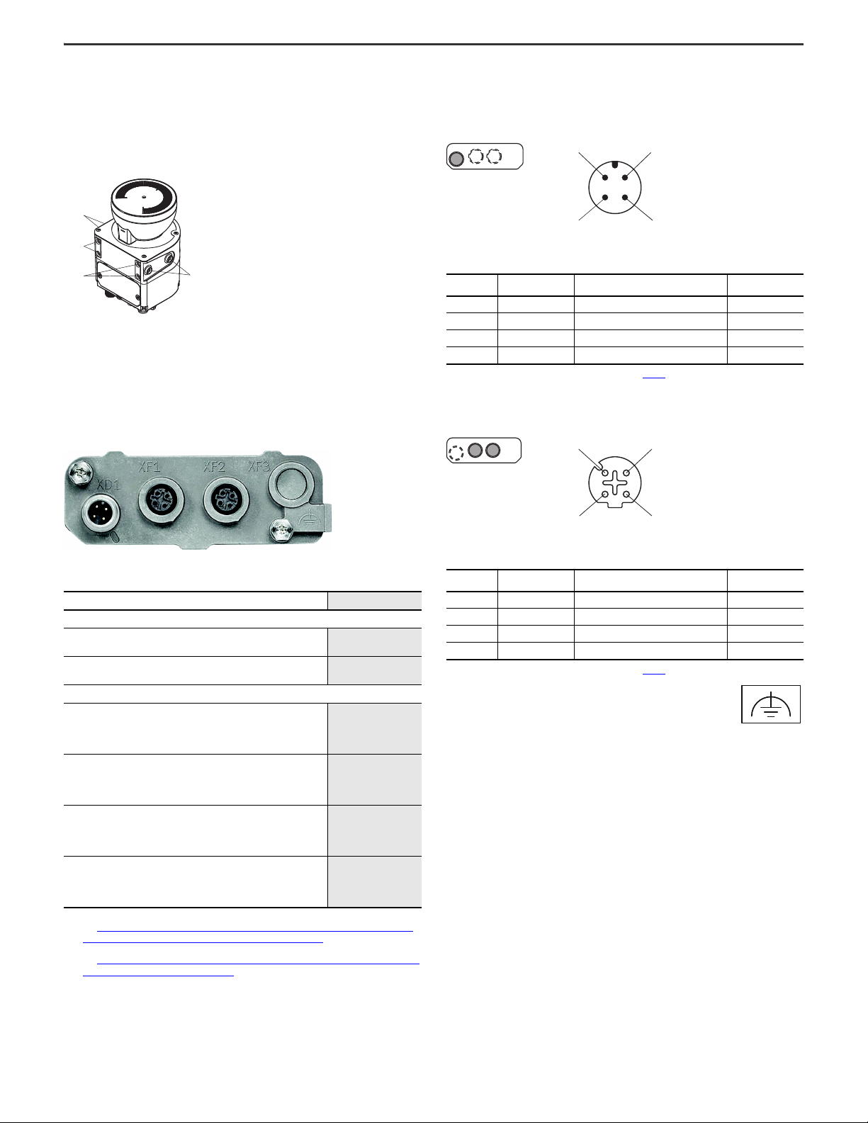
Connection Overview
Pin Assignment
Voltage Supply (Pwr) — XD1
Figure 1 - M12 male connector, 4-pin, A-coded
12
3 4
Table 2 - Voltage Supply Pin Assignment
Pin Designation Function
1 +24V DC Supply voltage +24V DC Brown
2 NC Not connected White
3 0V DC Supply voltage 0V DC Blue
4 FE Functional earth/shield Black
(1) Applies to the recommended connection cables (see Table 1 ).
EtherNet/IP Connection (E/IP) — XF1 and XF2
Figure 2 - M12 Female Connector, 4-pin, D-coded
3
4
Wire Color
(1)
2
1
Table 3 - EtherNet/IP™ Pin Assignment
Table 1 - Connection Cables
Description Cat. No.
Power Connection Cable
4-pin, straight M12 QD female with flying leads, yellow PVC jacket,
22 AWG, 250V, 4 A
4-pin, right M12 QD female with flying leads, yellow PVC jacket, 22
AWG, 2 50V, 4 A
Ethernet Cabling
M12 to Flying Leads
1585 Ethernet cables, 4 conductors, M12, straight male, standard,
flying leads, teal PUR, shielded, 100BASE-TX, 100 Mbit/s, high flex,
PUR, halogen-free, 10 million cycles
M12 to M12
1585 Ethernet cables, 4 conductors, M12, straight male, standard,
M12, teal PUR, shielded, 100BASE-TX, 100 Mbit/s, high flex, PUR,
halogen-free, 10 million cycles
M12 to M12
1585 Ethernet cables, 4 conductors, M12, straight male, standard,
M12, right-angle male, teal PUR, shielded, 100BASE-TX, 100 Mbit/s,
high flex, PUR, halogen-free, 10 million cycles
M12 to RJ45
1585 Ethernet cables, 4 conductors, M12, straight male, standard,
RJ45, straight male, teal PUR, shielded, 100BASE-TX, 100 Mbit/s,
high flex, PUR, halogen-free, 10 million cycles
(1) Replace the x with a 2 (2 m), 5 (5 m), or 10 (10 m) for standard cable lengths.
See rockwellautomation.com/en-us/products/hardware/allen-bradley/connection-devices/cables-
and-cordsets/dc-micro--m12-/dc-micro-cordsets-and-patchcords.html for additional information.
(2) Replace the x with a 2 (2 m), 5 (5 m), or 10 (10 m) for standard cable lengths.
See rockwellautomation.com/en-us/products/hardware/allen-bradley/connection-devices/network-
media/ethernet/1585-m12-and-variant-1.html for additional information.
889D-F4AC-x
889D-R4AC-x
1585D-M4UB-x
1585D-M4UBDM-x
1585D-M4UBDW-x
1585D-M4UBJM-x
(1)
(1)
(2)
(2)
(2)
(2)
Pin Designation Function
1 TX+ Send data + White/orange
2 RX+ Receive data + White/green
3 TX- Send data - Green
4RX- Receive data - Orange
(1) Applies to the recommended connection cables (see Table 1 ).
Wire Color
Alternative FE Connection
Screw connection of the alternate FE connection
• Screw: M5 x 12
• Tightening torque: 3.5…5 N•m
Suitable cable lugs
• Forked cable lug or ring cable lug
• Width: ≤10 mm (0.4 in.)
• Hole diameter for screw: typically 5.2 mm (0.2 in.)
The functional earth must be connected via one, and only one, of the available
FE connections:
• Pin on the M12 plug connector
• Thread on the M12 plug connector
• Alternative FE connection
The functional earth must be connected in a low-inductance manner and with an
adequate cross-section while keeping the cable length as short as possible.
Functional earth and protection earth must be isolated.
(1)
2 Rockwell Automation Publication 442L-IN006C-EN-P - February 2021
Page 3

SafeZone 3 Safety Laser Scanner Mounting Installation Instructions
Replace the Safety Laser Scanner
If the safety laser scanner is damaged or does not function properly, you must
replace the scanner.
A TX20 torx driver is required.
ATTENTION: Hazard due to lack of effectiveness of the
protective device.
Persons and parts of the body to be protected may not be
recognized if not observed.
If an unsuitable configuration is saved in the system plug, the
dangerous state is not ended or is not ended in time.
After replacement:
• Verify that the same system plug or a system plug with the
same configuration is used.
• Confirm that the safety laser scanner is aligned correctly.
IMPORTANT
The IP65 enclosure rating only applies if the safety
laser scanner is closed and the system plug is
mounted.
• Mount the system plug and cover plate.
• Close each M12 connector on the safety laser scanner
with a male cable connector or a protective cap.
- Tightening torque for connection:
0.4…0.6 N•m (3.54…5.31 lb•in)
- Tightening torque for protective caps:
0.6…0.7 N•m (5.31…6.19 lb•in)
• Mount the optics cover.
Replace the Safety Laser Scanner Completely
1. Disconnect the connecting cables from the system plug.
2. Unscrew the mounting screws and remove the nonfunctioning safety laser scanner.
3. Mount the new safety laser scanner, see Direct Mounting
on page 2.
4. Reconnect the connecting cables to the system plug.
5. Configure the safety laser scanner.
6. Perform commissioning again. Take particular care to conduct all
thorough checks described. For more information, see publication
442L-UM008
.
Replace the System Plug
A TX20 torx driver is required.
IMPORTANT
The IP65 enclosure rating only applies if the safety
laser scanner is closed and the system plug is
mounted.
• Mount the system plug and cover plate.
• Close each M12 connector on the safety laser scanner
with a male cable connector or a protective cap.
- Tightening torque for connection:
0.4…0.6 N•m (3.54…5.31 lb•in)
- Tightening torque for protective caps:
0.6…0.7 N•m (5.31…6.19 lb•in)
• Mount the optics cover.
IMPORTANT
Carefully plug in the system plug. Do not force it. The
contacts may break off or bend if too much force is
used.
Replace the Safety Laser Scanner Without System Plug
1. Verify that the environment is clean and clear of fog,
moisture, and dust.
2. Unscrew the system plug screws and remove the system
plug from the non-functioning safety laser scanner.
3. Unscrew the mounting screws and remove the nonfunctioning safety laser scanner.
4. Mount the system plug on the new safety laser scanner,
see Replace the System Plug
5. Mount the new safety laser scanner, see Direct Mounting
6. Check the effectiveness of the SafeZone 3 safety laser scanner. For more
information, see publication 442L-UM008
.
on page 2.
.
IMPORTANT
1. Verify that the environment is clean and clear of fog,
moisture, and dust.
2. Disconnect the connecting cables from the system plug.
3. If necessary, move the safety laser scanner to a clean
location.
4. Unscrew the system plug screws from the non-functioning
and remove the system plug from the safety laser scanner.
5. Carefully insert the new system plug into the appropriate mounting slot of
the safety laser scanner.
6. Screw in the system plug with the captive screws. Tightening torque is
2.25…2.75 N•m (19.9…24.3 lb•in).
7. Reconnect the connecting cables to the system plug.
8. Perform commissioning again. Take particular care to conduct all
thorough checks described. For more information, see publication
442L-UM008
Carefully plug in the system plug. Do not force it. The
contacts may break off or bend if too much force is
used.
.
Rockwell Automation Publication 442L-IN006C-EN-P - February 2021 3
Page 4

Rockwell Automation Support
Use these resources to access support information.
Technical Support Center
Knowledgebase
Local Technical Support Phone Numbers
Literature Library
Product Compatibility and Download Center
(PCDC)
Find help with how-to videos, FAQs, chat, user forums, and product notification updates. rok.auto/support
Access Knowledgebase articles. rok.auto/knowledgebase
Locate the telephone number for your country. rok.auto/phonesupport
Find installation instructions, manuals, brochures, and technical data publications. rok.auto/literature
Download firmware, associated files (such as AOP, EDS, and DTM), and access product release notes. rok.auto/pcdc
Documentation Feedback
Your comments help us serve your documentation needs better. If you have any suggestions on how to improve our content, complete the form at rok.auto/docfeedback.
Waste Electrical and Electronic Equipment (WEEE)
At the end of life, this equipment should be collected separately from any unsorted municipal waste.
Rockwell Automation maintains current product environmental compliance information on its website at rok.auto/pec.
Your comments help us serve your documentation needs better. If you have any suggestions on how to improve our content, complete the form at rok.auto/docfeedback.
For technical support, visit rok.auto/support.
Rockwell Otomasyon Ticaret A.Ş. Kar Plaza İş Merkezi E Blok Kat:6 34752 İçerenköy, İstanbul, Tel: +90 (216) 5698400 EEE Yönetmeliğine Uygundur
Allen-Bradley, expanding human possibility, Guardmaster, Rockwell Automation, and SafeZone are trademarks of Rockwell Automatio n, Inc.
EtherNet/IP is a trademark of ODVA, Inc.
Trademarks not belonging to Rockwell Automation are property of their respective companies.
Publication 442L-IN006C-EN-P - February 2021 | Supersedes Publication 442L-IN006B-EN-P-November 2020
Copyright © 2021 Rockwell Automation, Inc. All rights reserved. Printed in the U.S.A.
8020211
10002538942 Ver 01
 Loading...