

Page 1

Distributed Power System
High Power SA3000
AC Power Modules
850020 – 11xxx, 21xxx (534 Amp)
850020 – 12xxx, 22xxx (972 Amp)
850020 – 13xxx, 23xxx (1457 Amp)
Instruction Manual
S-3038
Page 2
Throughout this manual, the following notes are used to alert you to safety considerations:
ATTENTION:Identifies information about practices or circumstances that can lead to personal
injury or death, property damage, or economic loss.
!
Important: Identifies information that is critical for successful application and understanding of the product.
ATTENTION:Only qualified personnel familiar with the construction and operation of this
equipment and the hazards involved should install, adjust, operate, or service this equipment.
!
Read and understand this manual and other applicable manuals in their entirety before
proceeding. Failure to observe this precaution could result in severe bodily injury or loss of life.
ATTENTION:DC bus capacitors retain hazardous voltages after input power has been
disconnected. After disconnecting input power, wait ten (10) minutes for the DC bus capacitors
to discharge. Open the cabinet doors and check the voltage across the DC bus bars, 347 A,B,C
(+ bus) and 345 A,B,C (- bus), with an external voltmeter to ensure the DC bus capacitors are
discharged before touching any internal components. Failure to observe this precaution could
result in severe bodily injury or loss of life.
ATTENTION:The user must provide an external, hardwired emergency stop circuit outside of the
drive circuitry. This circuit must disable the system in case of improper operation. Uncontrolled
machine operation may result if this procedure is not followed. Failure to observe this precaution
could result in bodily injury.
ATTENTION: The user is responsible for conforming with all applicable local, national, and
international codes. Failure to observe this precaution could result in damage to, or destruction
of, the equipment.
The information in this users manual is subject to change without notice.
AutoMax™ is a trademark of Rockwell Automation
©1998 Rockwell International Corporation
Page 3

Chapter 1 Introduction
1.1 Standard Features...........................................................................................1-1
1.2 Optional Features............................................................................................1-2
1.3 Power Module Part Numbers ..........................................................................1-3
1.4 Related Publications........................................................................................ 1-4
1.5 Related Hardware and Software ..................................................................... 1-4
Chapter 2 Mechanical/Electrical Description
2.1 Mechanical Description ...................................................................................2-1
2.1.1 Power Module Components..................................................................2-1
2.2 Electrical Description .......................................................................................2-6
Chapter 3 Installation Guidelines
3.1 Installation Planning ........................................................................................3-1
3.2 Wiring .............................................................................................................. 3-2
3.2.1 Fuses ....................................................................................................3-2
3.2.2 Wire Sizes.............................................................................................3-2
3.2.3 Wire Routing ......................................................................................... 3-3
3.3 Grounding........................................................................................................ 3-3
3.4 Installing the Power Module Cabinet.. ....... ...... ....... ...... ....... ...... ....... ...... .........3-3
C
ONTENTS
Chapter 4 Diagnostics and Troubleshooting
4.1 Required Test Equipment................................................................................4-1
4.2 Power Module Tests with Input Power Off ...................................................... 4-2
4.3 Power Module Faults and Warnings................................................................ 4-4
4.3.1 Power Module Faults ............................................................................ 4-5
4.3.1.1 DC Bus Overvoltage Fault ......................................................4-5
4.3.1.2 DC Bus Overcurrent Fault....................................................... 4-5
4.3.1.3 Ground Current Fault..............................................................4-5
4.3.1.4 Instantaneous Overcurrent Fault ............................................4-6
4.3.1.5 Local Power Interface Fault ....................................................4-6
4.3.1.6 Charge Bus Time-Out Fault ....................................................4-6
4.3.1.7 Overtemperature Fault...................................... ....... ...... ....... .. 4-6
4.3.2 Power Module Warnings ....................................................................... 4-7
4.3.2.1 DC Bus Overvoltage Warning................................................. 4-7
4.3.2.2 DC Bus Undervoltage Warning............................................... 4-7
4.3.2.3 Ground Current Warning......................................................... 4-7
4.3.2.4 Load Sharing Warning ............................................................4-7
4.3.2.5 Overtemperature Warning .................................................... .. 4-8
4.4 Replacing Power Module Fuses and Sub-Assemblies.................................... 4-8
4.4.1 Replacing Fuses ...................................................................................4-8
4.4.2 Replacing an IGBT Phase Module Assembly ..................................... 4-15
4.4.2.1 Replacing an IGBT................................................................ 4-17
4.4.3 Replacing the Pre-charge Assembly...................................................4-17
4.4.4 Replacing a Blower Assembly............................................................. 4-18
4.4.4.1 Replacing a Blower Filter...................................................... 4-19
4.4.5 Replacing a Bus Capacitor Assembly ................................................. 4-19
4.5 Replacing the Power Module Cabinet ........................................................... 4-20
Table of Contents
I
Page 4

Appendix A Technical Specifications........................................................................................... A-1
Appendix B SA3000 Internal DC Bus Control ............................................................................. B-1
Appendix C Replacement Parts ....... ...... ....... ...... ....... ...... ...... ....... ....................................... ...... .. C-1
Index ..................................... ...... ....... ...... ....... ...... ....................................... ...... ....... ..Index-1
II
High Power SA3000 AC Power Modules
Page 5

List of Figures
Figure 1.1 – SA3000 Power Module Part Numbering Scheme ................................1-3
Figure 2.1 – 534A SA3000 Power Module Components.......................................... 2-3
Figure 2.2 – 972A 3000A Power Module Components ............................................2-4
Figure 2.3 – 1457A SA3000 Power Module Components........................................ 2-5
Figure 2.4 – Drive I/O and Processor Card Detail .................................................... 2-8
Figure 2.5 – 534A SA3000 Power Module Circuitry ................................................. 2-9
Figure 2.6 – 972A SA3000 Power Module Circuitry ...............................................2-10
Figure 2.7 – 1457A SA3000 Power Module Circuitry .............................................2-11
Figure 3.1 – 534A Power Module Mounting Dimensions (Single-Bay).....................3-4
Figure 3.2 – 972A Power Module Mounting Dimensions (Double-Bay) ...................3-5
Figure 3.3 – 1457A Power Module Mounting Dimensions (Triple-Bay)....................3-6
Figure 3.4 – SA3000 Power and Ground Connections.............................................3-7
Figure 4.1 – DC Bus Voltage Measuring Points ....................................................... 4-3
Figure 4.2 – 534A SA3000 Power Module Fuse Locations.................................... 4-10
Figure 4.3 – 972A SA3000 Power Module Fuse Locations.................................... 4-11
Figure 4.4 – 1457A SA3000 Power Module Fuse Locations.................................. 4-12
Figure 4.5 – 115VAC Control Power Supply Assemblies....................................... 4-13
Figure 4.6 – 25 KHz. Power Supply........................................................................4-14
Figure 4.7 – IGBT Module Assembly Mounting Bolt Locations ..............................4-17
Table of Contents
III
Page 6

IV
High Power SA3000 AC Power Modules
Page 7

List of Tables
Table 1.1 – SA3000 Power Module Configurations..................................................1-1
Table 1.2 – SA3000 Documentation (Binder S-3001) .............................................. 1-4
Table 3.1 – Fuse Ratings..........................................................................................3-2
Table 3.2 – Recommended DC Bus Input and AC Output Wire Sizes..................... 3-2
Table 3.3 – Terminal Tightening Torques.................................................................3-3
Table 4.1 – DC Bus and Terminal Tests...................................................................4-4
Table 4.2 – IGBT Tests.............................................................................................4-4
Table 4.3 – SA3000 Power Module Faults (Register 202/1202) ..............................4-5
Table 4.4 – SA3000 Warning Register 203 /1203 .................................................... 4-7
Table 4.5 – Power Module Replacement Fuse Specifications .................................4-9
Table of Contents
V
Page 8

VI
High Power SA3000 AC Power Modules
Page 9

C
HAPTER
1
Introduction
The High Power SA3000 Power Modules are variable-voltage, variable-frequency
power inverters for Distributed Power System (DPS) drives. They are designed to
operate from a separate converter (diode bridge, phase-controlled rectifier, SB3000
Synchronous Rectifier, or a common DC bus supply) to drive induction motors at
variable speeds using pulse-width modulation (PWM) technology.
The SA3000 Power Modules are configured in three output current ratings: 534 amp,
972 amp, and 1457 amp when used at a 2 kHz carrier frequency. They have a range
of AC Input voltage ratings. See table 1.1. Nominal DC bus voltage may range from
300 to 800 VDC.
4 kHz operation requires a derating of the AC input current and DC output load current
when compared with operation at 2 kHz. See table 1.1.
The SA3000 Power Module output current ratings given are 100% continuous with no
overload. They may be derated for lower current ratings with overload capability.
Table 1.1 – SA3000 Power Module Configurations
Output
Base Part
Number
850020-11xxx
850020-21xxx
850020-12xxx
850020-22xxx
850020-13xxx
850020-23xxx
1. Output current ratings at 40° C (104° F) ambient air temperature and 60 Hz. Reduce all output current ratings by 5% when the Power
Module blowers are operated from a 50 Hz power source.
2. Contact Rockwell Automation for duty cycle ratings.
3. 800 VDC if an SA3000/SA3100 unit is used to supply 575 VAC output to the motor.
Cabinet
Type
One Bay
Two Bays 250-820V 972A 890A 1275A 230-460V
Three Bays 250-820V 1457A 1335A 1900A 230-460V
DC Bus
Input Volts
250-820V
Amps
(2 KHz)
3
534A 445A 700A 230-460V
Output
Amps
(4 KHz)
1
Peak
Amps
2
AC Input
Volts
1.1 Standard Features
High Power SA3000 Power Modules have the following standard features:
•
IGBT power semiconductor bridge
•
Carrier switching frequencies from 2 to 4 kHz
•
Input and output short-circuit protection
Introduction
•
Fiber-optic communication with the DPS host, the Universal Drive Controller (UDC)
module
1-1
Page 10

•
Auto-tuning
•
Standard cabinet paint
1.2 Optional Features
The following optional features are available for High Power SA3000 Power Modules
•
DC bus voltage meter
•
Motor ammeter
•
Motor voltmeter
•
Motor torque meter
•
Motor frequency meter
•
Main disconnect
•
Pre-charge
•
Separation of critical and non-critical 115 VAC control power
•
DC bus top hat enclosure
•
Custom cabinet paint
1-2
High Power SA3000 AC Power Modules
Page 11
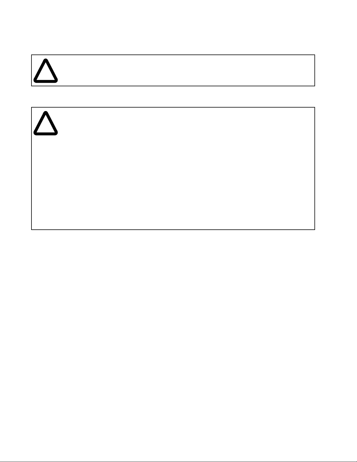
1.3 Power Module Par t Numbers
SA3000 Power Module part numbers are organized by the number of cabinet bays,
i.e., single (534A), double (972A), or triple (1457A) cabinet bay configurations, in
combination with the supplied options. See figure 1.1.
850020 -1
Cabinet Top
Enclosures:
R
1
Size of Unit
S
T
Pre-charge:
Main
Disconnect:
Meters:
1 = 534A Output - 1 Bay Unit
2 = 972A Output - 2 Bay Unit
3 = 1457A Output - 3 Bay Unit
1 = DC Bus Assembly Enclosure
2 = DC Bus Top Hat Enclosure
T = Supplied - Standard Cabinet Paint
Y = Supplied - Custom Cabinet Paint
X = Not Supplied - Standard Cabinet Paint
Z = Not Supplied - Custom Cabinet Paint
S = Supplied - Standard Cabinet Paint
W = Supplied - Custom Cabinet Paint
X = Not Supplied - Standard Cabinet Paint
Z = Not Supplied - Custom Cabinet Paint
R = Supplied - Standard Cabinet Paint
V = Supplied - Custom Cabinet Paint
X = Not Supplied - Standard Cabinet Paint
Z = Not Supplied - Custom Cabinet Paint
(1)
Introduction
SA3000 Power Module - Base Part Number
1. Top Hat Enclosure accommodates bending radius of DC bus cable (customer supplied).
Figure 1.1 – SA3000 Power Module Part Numbering Scheme
1-3
Page 12

1.4 Related Publications
This manual describes the hardware components of the SA3000 Inverter Power
Module. The other instruction manuals in binder S-3001 describe the SA3000
software, regulator, and communications. Table 1.1 lists the document part numbers.
Table 1.2 – SA3000 Documentation (Binder S-3001)
Document Document Part Number
SA3000 Information Guide S-3023
Drive System Overview S-3005
Universal Drive Controller Module S-3007
Fiber Optic Cabling S-3009
SA3000 Drive Configuration & Programming S-3016
SA3000 Power Module Interface Rack and Modules S-3019
Medium Power SA3000 Power Modules S-3020
SA300 Diagnostics, Troubleshooting, & Start-Up
Guidelines
High Power SA3000 Power Modules S-3038
SA3000 Power Modules are designed to be operated from a common DC bus, which
can be supplied by a Distributed Power System SB3000 Synchronous Rectifier. Refer
to the following manuals for information on the SB3000 Synchronous Rectifier system:
•
S-3034 SB3000 Synchronous Rectifier Configuration and Programming
•
S-3043 High Power SB3000 Power Modules
1.5 Related Hardware and Software
The following related hardware may be purchased separately:
•
P/N 613613-xxS Fiber-optic cable (cable length xx is specified in meters)
•
B/M O-57552 Universal Drive Controller (UDC) module
•
B/M O-57652 Universal Drive Controller (UDC) module EM
S-3021
1-4
High Power SA3000 AC Power Modules
Page 13

Mechanical/Electrical Description
This chapter provides an overview the SA3000 Power Module’s main components and
their mechanical and electrical characteristics.
2.1 Mechanical Description
The High Power SA3000 Power Modules are variable-voltage, variable-frequency
inverters that are housed in protective sheet metal enclosures. The Power Modules
are supplied in single, double, and triple bay cabinet configurations, depending upon
the current rating. See figures 2.1 to 2.3. Power Module dimensions are shown in
figures 3.1 to 3.3.
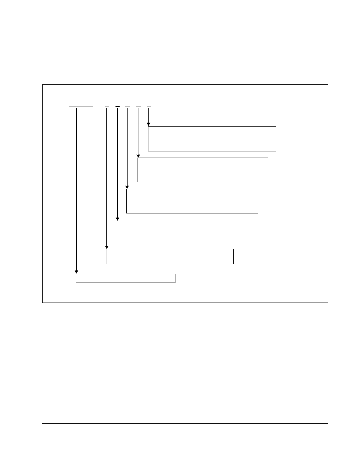
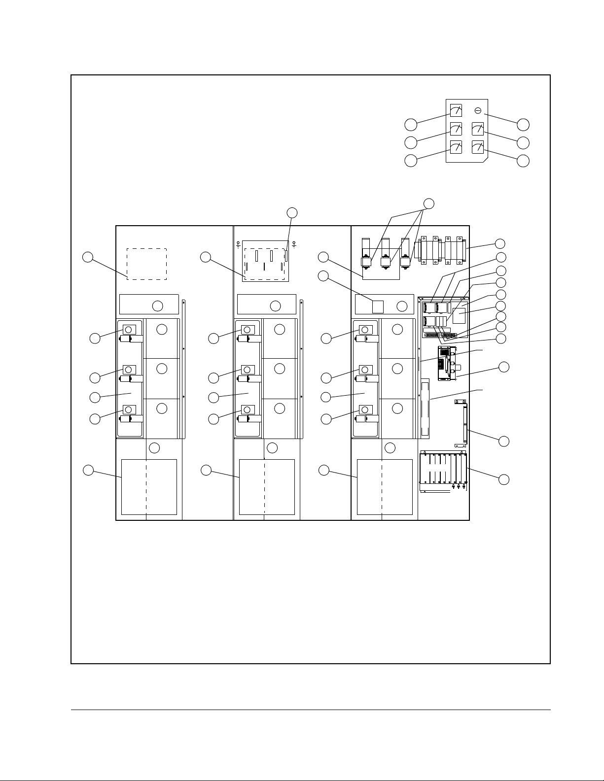
2.1.1 Power Module Components
The Power Modules have the following main components:
Phase modules
Each Phase module contains four semiconductor IGBTs (insulated gate bi-polar
transistors). IGBT pairs are switched on and off by the integrated Snubber/Gate Driver
module to provide modulated phase voltages (U,V,W) to the motor. Fuses and
thermostats are provided to protect the IGBT modules.
C
HAPTER
2
Snubber/Gate Driver Module
Each Snubber/Gate Driver module, mounted on the IGBT phase module, receives
gating signals via fiber-optic cabling from the GDI module(s) in the PMI rack and
translates the signals into the appropriate voltage and current levels to turn the IGBTs
on and off. Feedback, indicating the integrity of the phase module and IGBTs, is then
sent back to the GDI module(s).
This module also provides snubber circuitry (resistors, diodes, and capacitors) to
control voltage overshoot and undershoot when the IGBTs are switching.
Fiber-Optic Communication
Fiber-optic cabling is used to transmit gate driver signals from the Gate Driver
Interface (GDI) module.These signals are used to turn the IGBTs on and off. IGBT
module feedback status information is sent via the fiber-optic cabling back to the GDI
module(s) in the PMI rack. Fiber-optic cabling is immune to electromagnetic and radio
frequency interference (EMI/RFI) and eliminates ground loops. For more information
on fiber-optic cabling refer to the Distributed Power System Fiber-Optic Cabling
instruction manual (S-3009).
Mechanical/Electrical Description
2-1
Page 14

Local Power Interface module (LPI)
The LPI module is the interface between the SA3000 Power Module and the PMI rack.
It is through this module that information is sent to the SA3000 Power Module and
feedback data is sent back to the PMI rack.
Capacitor Bank Assembly
The capacitor bank's electrolytic capacitors store power locally for the IGBTs.
115 VAC Power Supply Assemb ly
Power Supply Assembly P/N 850100-3S allows for the separation of critical (PMI rack,
25 KHz power supply, DC power supplies) and non-critical (blower motors) 115 VAC
power via two 115 VAC terminal boards and two 25A circuit breakers. Removing the
jumper wires between the two terminal boards provides the separation of critical and
non-critical power. The circuit breakers can be locked in either the ON or OFF position
when the optional locking mechanism is used.
Power Supply Assembly P/N 850100-3R provides one 115 VAC terminal board and
one 25A circuit breaker. This assembly distributes 115 VAC power to the DC power
supplies, the 25 KHz power supply, the PMI rack, and the Power Module blowers. See
figure 4. 5.
25 KHz Power Supply Assembly
The 25 KHz Power Supply Assembly provides power to the six IGBT gate drivers in
each Power Module. 25KHz AC power is used for transformer isolation and noise
immunity. Input power is provided by the 115 VAC power supply. See figure 4.6.
DC Bus Voltage Meter (Option)
The DC Bus Voltage meter, which is connected directly across the DC bus, measures
the DC bus voltage being applied to the power module.
Output Meters (Option)
These meters measure the AC voltage (0-600V), current (0-200 percent of full load),
torque (200-0-200 percent of full load), and frequency (120-0-120Hz) being applied to
the motor. These meters are connected to the PMI Processor’s meter ports, which are
under software control.
Main Disconnect (Option)
Depending on system requirements, a DC input disconnect may be provided. Note
that if a disconnect is supplied, the pre-charge assembly option must also be used if
the Power Module is operating from a constant potential DC bus supply.
Pre-charge Assembly (Option)
The Pre-charge Assembly consists of a contactor, pre-charge resistors, and a printed
circuit board assembly. The contactor bypasses the pre-charge resistor after the bus
voltage reaches a programmable threshold value. A pre-charge control module
communicates with the LPI module and controls the pre-charge contactor.
2-2
High Power SA3000 AC Power Modules
Page 15
18
15
15
15
20
14
6
OUTPUT METER PANEL
(OPTIONAL)
MOTOR
GRD
AC MOTOR OUTPUT
U
MOTOR
GRD
V
W
DISCONNECT SWITCH
A
M
P
F
5
8
9
24
26
23
25
19
POWER MODULE A
PRE-CHARGE ASSEMBLY
4
2
F103
CAPACITOR
3
BANK
PHASE U
2
F104
PHASE V
+24VPS-24V
PS
PS PS
±15V
±15V
PS
PS
25KHZ PS
1
B
C
1
U
U
B
F
F
C
1
3
1
22
11
17
16
7
SALES ORDER
NAMEPLATE
13
CUSTOMER CONTROL WIRING
28
IF USED, THE O U TPUT METER
PANEL IS MOUNTED IN THE CABINET
DOOR OF POWER MODULE A.
27
2
F105
PHASE W
BLOWER
1
ASSEMBLY
PMI RACK
LPI
MODULE
GDI
A
.
D
O
M
.
R
W
P
6
T
O
L
S
10
12
1. Blower Assembly 2. IGBT Phase Module Assembly 3. Capacitor Bank Assembly
4. Pre-charge Assembly
5. DC Disconnect Assembly
1
6. DC bus fuse
7. +/- 15V DC Power Supply 8. 24V DC Power Supplies 9. 115VAC C.B. - Non Critical Pwr
10. Local Power Interface Module 11. 250VA Isolation Transformer 12. Power Module Interface Rack
13. 25KHz Power Supply 14. Reactor Assembly 15. LEM Output Current Sensor
16. Control Fuse (1FU) 17. Control Fuse (3FU) 18. DC Feedback Module
19. 115VAC C.B. - Critical Power 20. Blower Filter 21. Motor Feedback Resistors
22. Power Supply Assembly
25. Motor Ammeter
28. Motor Frequency
1
1
1. Optional
Mechanical/Electrical Description
23. Door Interlock Bypass Switch
26. Motor Voltmeter
Figure 2.1 – 534A SA3000 Power Module Components
1
1
24. DC Bus Voltage Meter
27. Motor Torque Meter
1
1
2-3
Page 16
OUTPUT METER PANEL
(OPTIONAL)
IF USED, THE O U TPUT METER
PANEL IS MOUNTED IN THE CABINET
DOOR OF POWER MODULE A.
24
26
28
23
25
27
15
15
14
15
20
21
MOTOR
GRD
AC MOTOR OUTPUT
U V
MOTOR
GRD
W
14
MOTOR
GRD
B
A
M
M
P
P
F
F
18
POWER MODUL E B
PRE-CHARGE ASSEM B LY
POWER MODUL E A
PRECHARGE ASSEMBLY
4
2
F103
PHASE U
K
N
A
B
15
F103
2
F104
3
F105
PHASE V
R
O
T
I
C
A
P
A
C
2
PHASE W
BLOWER
1
ASSEMBLY
15
15
F104
3
F105
2
PHASE U
K
N
A
B
2
PHASE V
R
O
T
I
C
A
P
A
C
2
PHASE W
1
ASSEMBLY
20
6
DISCONNECT SWITCH
+24V
4
BLOWER
+24V
PS
PS PS
±15V
±15V
PS
PMI RACK
-24V
PS
1
U
U
B
F
F
C
3
1
1
--
25KHZ PS
MODULE
5
8
9
19
22
1
B
C
11
17
16
7
SALES ORDER
NAMEPLATE
13
CUSTOMER
CONTROL WIRING
LPI
GDIGDI
B
A
.
.
D
D
O
O
M
M
.
.
R
R
W
W
P
P
7
6
T
T
O
O
L
L
S
S
10
12
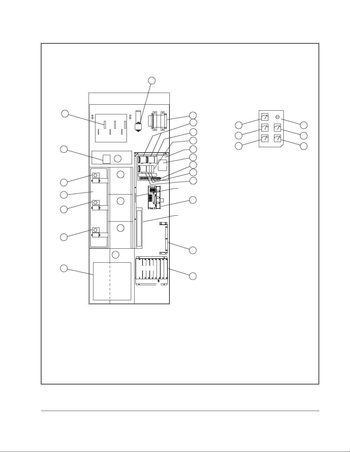
1. Blower Assembly 2. IGBT Phase Module Assembly 3. Capacitor Bank Assembly
4. Pre-charge Assembly
5. DC Disconnect Assembly
1
6. DC bus fuse
7. +/- 15V DC Power Supply 8. 24V DC Power Supplies 9. 115VAC C.B. - Non Critical Pwr
10. Local Power Interface Module 11. 250VA Isolation Transformer 12. Power Module Interface Rack
13. 25KHz Power Supply 14. Reactor Assembly 15. LEM Output Current Sensor
16. Control Fuse (1FU) 17. Control Fuse (3FU) 18. DC Feedback Module
19. 115VAC C.B. - Critical Power 20. Blower Filter 21. Motor Feedback Resistors
22. Power Supply Assembly
25. Motor Ammeter
1
28. Motor Frequency
1. Optional
1
23. Door Interlock Bypass Switch
26. Motor Voltmeter
Figure 2.2 – 972A 3000A Power Module Components
1
2-4
1
24. DC Bus Voltage Meter
27. Motor Torque Meter
High Power SA3000 AC Power Modules
1
1
Page 17
OUTPUT METER PANEL
(OPTIONAL)
IF USED, THE O U TPUT METER
PANEL IS MOUNTED IN THE CABINET
DOOR OF POWER MODULE A.
24
26
28
23
25
27
21
6
C
M
P
F
4
22
2
2
BLOWER
ASSEMBLY
DISCONNECT SWITCH
1
+24VPS-24V+24V
B
PS
PS PS
C
1
U
U
±15V
±15V
B
F
F
C
PS
1
3
1
25KHZ PS
LPI
MODULE
GDIGD
A
.
D
PMI RACK
O
M
.
R
W
P
6
T
O
L
S
I
GDI
B
C
.
.
D
D
O
O
M
M
.
.
R
R
W
W
P
P
8
7
T
T
O
O
L
L
S
S
5
8
9
19
22
11
17
16
7
SALES ORDER
NAMEPLATE
13
CUSTOMER CONTR OL
WIRING
10
12
MOTOR
GRD
AC MOTOR OUTPUT
14
14
MOTOR
GRD
B
WVU
14
A
M
M
P
P
F
F
18
POWER MODULE APOWER MODULE BPOWER MODULE C
PRE-CHARGE AS SE MBLY
4
PRE-CHARGE ASSEMBLY
4
PRE-CHARGE ASSEMBL Y
2
15
F103
PHASE U
K
N
A
B
2
15
F104
3
15
F105
PHASE V
R
O
T
I
C
A
P
A
C
2
PHASE W
BLOWER
1
ASSEMBLY
15
F103
PHASE U
K
N
A
B
2
15
F104
3
15
F105
PHASE V
R
O
T
I
C
A
P
A
C
2
PHASE W
BLOWER
1
ASSEMBLY
2020
15
15
F103
F104
3
15
F105
PHASE U
K
N
A
B
PHASE V
R
O
T
I
C
A
P
A
C
PHASE W
1
20
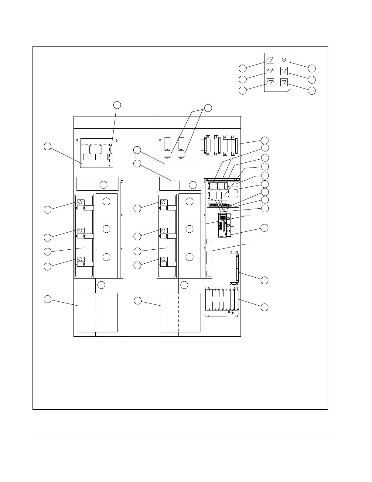
1. Blower Assembly 2. IGBT Phase Module Assembly 3. Capacitor Bank Assembly
4. Pre-charge Assembly
5. DC Disconnect Assembly
1
6. DC bus fuse
7. +/- 15V DC Power Supply 8. 24V DC Power Supplies 9. 115VAC C.B. - Non Critical Pwr
10. Local Power Interface Module 11. 250VA Isolation Transformer 12. Power Module Interface Rack
13. 25KHz Power Supply 14. Reactor Assembly 15. LEM Output Current Sensor
16. Control Fuse (1FU) 17. Control Fuse (3FU) 18. DC Feedback Module
19. 115VAC C.B. - Critical Power 20. Blower Filter 21. Motor Feedback Resistors
22. Power Supply Assembly
25. Motor Ammeter
28. Motor Frequency
1
1
1. Optional
Mechanical/Electrical Description
23. Door Interlock Bypass Switch
26. Motor Voltmeter
Figure 2.3 – 1457A SA3000 Power Module Components
1
1
24. DC Bus Voltage Meter
27. Motor Torque Meter
1
1
2-5
Page 18
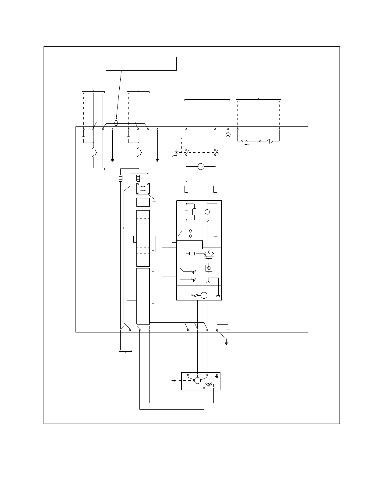
2.2 Electrical Description
DC bus input power is applied to the Power Module through terminals 45 (–) and
47 (+), passes through the optional DC bus disconnect and in-line fuses, and is then
fed to the optional pre-charge circuitry. See figures 2.4 to 2.7.
When pre-charge circuitry is present and DC input power is applied, the internal DC
bus begins charging through the pre-charge resistors. Once the DC bus capacitors
are fully charged (per the programmable threshold value) and all pre-charge criteria
are met, the internal pre-charge contactor closes and bypasses the pre-charge
resistors. If the DC bus disconnect option is not used, the bus supply is responsible for
the charging operation. Refer to Appendix B for additional information on SA3000
internal DC bus control.
The DC bus voltage is filtered and stored by the electrolytic capacitors. Discharge
resistors are designed to discharge the capacitors down to 50 VDC within 5 minutes
after power is removed from the input terminals. However, if a DC bus fuse has blown,
it is possible for a charge to be stored on the DC bus capacitors without being
indicated on the DC bus voltmeter. Wait 10 minutes before working on the unit. Be
sure to measure the DC bus potential of each Power Module capacitor bank before
touching any internal circuitry. See figure 4.1 for test point locations.
ATTENTION:
power has been disconnected. After disconnecting input power, wait ten
!
When the DC bus operating voltage is reached, the connected Inverter Power
Modules may be operated. Note that if an SB3000 Power Module is used to supply the
DC bus, the SB3000 Power Module cannot support the loading of SA3000 Inverter
Power Modules when the soft-charge resistors in the SB3000 are limiting the bus
charging current.
!
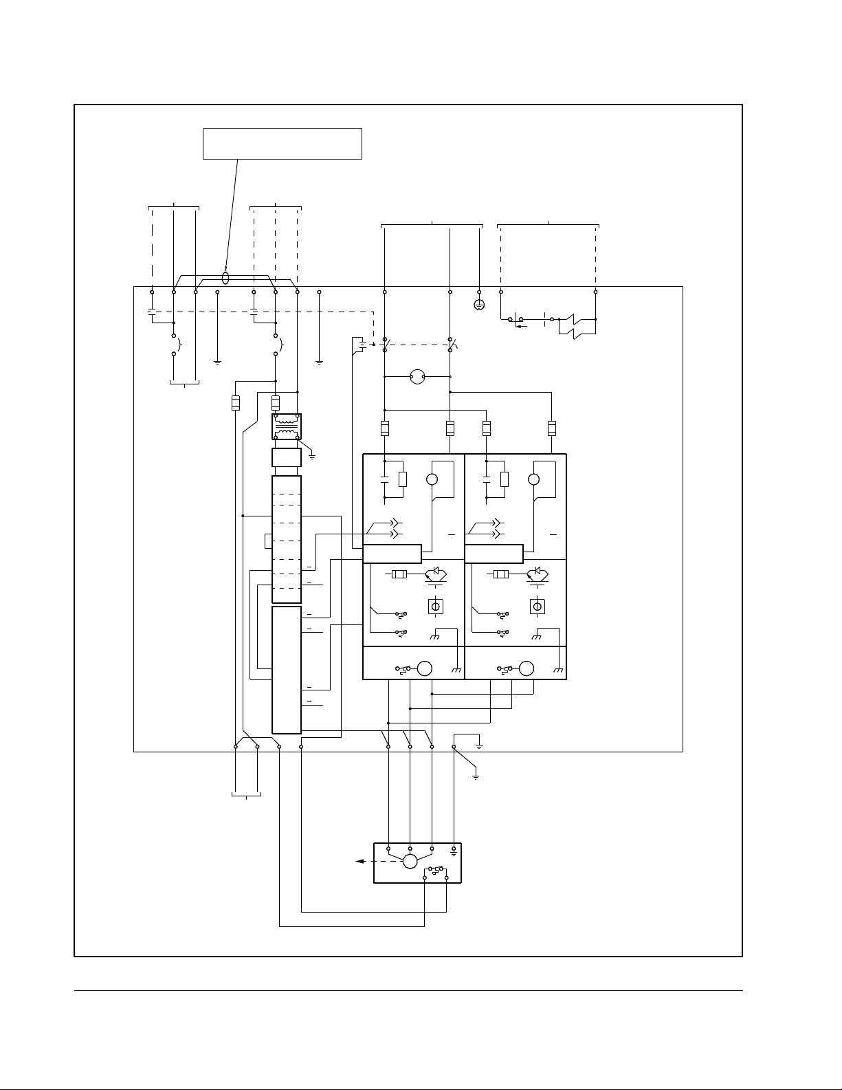
The SA3000 inverter power circuitry uses the filtered DC bus voltage to provide the
variable-voltage, variable-frequency output to the motor (terminals U, V, W). The 972
Amp and 1457 Amp units have reactors for load sharing on their outputs. The IGBTs
are switched by the gate drivers on the IGBT phase module under the control of the
PMI rack. A LEM sensor is located on each output phase (U,V,W) of each SA3000
Inverter Power Module (A,B, or C) to provide output current feedback for overcurrent
protection.
(10) minutes for the DC bus capacitors to discharge. Open the cabinet
doors and check the voltage across the DC bus bars, 347 A,B,C (+ bus)
and 345 A,B,C (- bus), with an external voltmeter to ensure the DC bus
capacitors are discharged before touching any internal components.
Failure to observe this precaution could result in severe bodily injury or
loss of life.
ATTENTION:
Module must be in standby or in regeneration whenever the SB3000
Power Module’ s pre-charge contactor opens. The SB3000 Power
Module’s soft-charge resistors may fail if this interlocking restriction is
not observed. Failure to observe this precaution could result in damage
to, or destruction of, the equipment.
DC bus capacitors retain hazardous voltages after input
When used with an SB3000 bus supply , the SA3000 Power
2-6
High Power SA3000 AC Power Modules
Page 19
Each SA3000 Inverter Power Module connected to an SB3000 Power Module
supplied DC bus must have a separate pre-charge resistor and contactor to limit the
current into its capacitor bank. It is the responsibility of the application tasks to make
sure that the SB3000 Power Module is in run before the SA3000 Inverter Power
Module is put into run.
ATTENTION:When used with an SB3000 Power Module, the SB3000
Power Module must be in run before the SA3000 Inverter Power Module
!
If the SB3000 Power Module is not in run, the DC bus voltage will not be high enough
to support the full rating of the SA3000 Inverter Power Module. If the SB3000 Power
Module is shut down due to a fault condition, controlled shutdown of the SA3000
Power Module is the responsibility of the application program running in the SA3000
UDC module.
is put into run. If the pre-charge contactor supplying the SB3000 Power
Module is not closed, running the SA3000 Power Module will damage
the SB3000 pre-charge resistors. Failure to observe this precaution could
result in damage to, or destruction of, the equipment.
Mechanical/Electrical Description
2-7
Page 20
YYYL
FROM 115VAC
YYYN
INDUSTRIAL
DUTY
BRUSHLESS
RESOLVER
P/N
800123-x
DRIVEN BY
MOTOR
PMI RACK AND OPTIONAL
AUTOMATE I/O RAILS
ARE MOUNTED
IN POWER MODULE
ESR
BN
REFERENCE
INPUT
(ROTOR)
SINE
OUTPUT
(STATOR)
COSINE
OUTPUT
(STATOR)
(+)
R1
(-)
R2
(+)
S1
(-)
S3
(+)
S2
(-)
S4
FROM
ANALOG
SIGNAL
FIBER OPTIC COMM. LINK
FROM UDC CARD
I/O RAIL
(IF USED)
FROM T.B. (P2 & N)
DRIVE I/O
B/M O-60031
(C3)
XXX01
XXX03
XXX05
XXX07
XXX11
REF. OUT(+)
XXX21
XXX22
XXX23
XXX24
XXX26
XXX25
XXX31
XXX32
AC
AC
AC
DC
REF. OUT(-)
SIN INPUT(+)
SIN INPUT(-)
COS INPUT(+)
COS INPUT(-)
EXT. TRIG(+)
EXT. TRIG(-)
ANALOG IN(+)
ANALOG IN(-)
SHIELD
1
2
3
4
5
6
(+)
(HI)
AUX
IN1
(HI)
AUX
IN2
(HI)
AUX
IN3
(HI)
AUX
IN4
(HI)
AUX
IN5
(HI)
MCR
(HI)
AUX
OUT
(HI)
ORG
BLU
1RPI
A
3
C AUX IN1
5
E
7
H
9
K AUX IN4
11
M AUX IN5
13
15
S AUX OUT
(+)
1
A
(-)
2
B
3
(+)
D
4
(-)
C
(+)
5
E
(-)
6
F
(+)
7
H
(-)
8
J
1
(+)
P
2
(-)
N
SHLD
3
R
PROCESSOR
B/M
O-60021
(C2)
FIBER OPTIC
COMM LINK
(P2)
XMT
(P3)
RCV
RAIL
PORTS
0
(P5)
1
AC POWER
TECH MODULE
B/M 60023
SYNCH XFER
INTERFACE
RPI
R201_B0
(C3-P2)
R201_B1
AUX IN2
R201_B2
AUX IN3
R201_B3
R201_B4
R201_B5
MCRP
R101_B1
0.5 SECOND
OFF-DELAY AFTER
RPI GOES "LOW"
R101_B4
(C3-P1)
REFERENCE
OUTPUT
SINE
INPUT
COSINE
INPUT
EXTERNAL
TRIGGER
ISOLATED
(±10V=(±2047)
±10V
METER(P4)
PORTS
(P1)
POWER
MODULE
2RPI
(LO)
B
AUX
IN1
4
(LO)
D
AUX
IN2
6
(LO)
F
AUX
IN3
8
(LO)
J
AUX
IN4
10
(LO)
L
AUX
IN5
12
(LO)
N
14
MCR
XXX14
(LO)
R
AUX
OUT
16
T
(P1)
+
1
COM
+
2
COM
+
3
COM
+
4
COM
(C4)
(P1)
(P2)
(LO)
XXX16
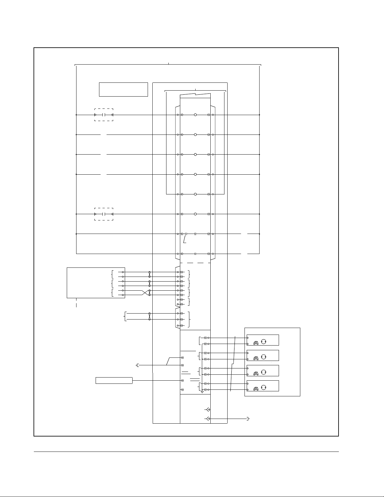
CABLE
RUN PERMISSIVE
INTERLOCK
MOTOR THERMOSTAT
BLOWER MOTOR
STARTER FEEDBACK
OPTIONAL METER PACKAGE
0-600V
CALIB
0-200%
CALIB
120Hz-0-120Hz
CALIB
200%-0-200%
CALIB
MOUNTED TO CABINET DOOR
OF POWER MODULE A
TO PARALLEL
INTERFACE MODULE
PMI RACK SLOT C5
MOTOR
VOLTS
MOTOR
CURRENT
MOTOR
FREQUENCY
MOTOR
TORQUE
2-8
Figure 2.4 – Drive I/O and Processor Card Detail
High Power SA3000 AC Power Modules
Page 21
NOTE: THESE JUMPERS ARE REMOVED
WHEN A SEPARATE 115 VAC SUPPLY
IS USED FOR THE PMI RACK.
115VAC FROM A-C
DISTRIBUTION
X
X
X
L
1
A
L1A
X
X
X
L
1
L2L1
C
B
1
TO
BLOWERS
BELOW
CONDITIONED POWER
FROM CRITICAL 115VAC
SUPPLY DISTRIBUTION
W
W
W
D
1
D1
FROM 115VAC
(
R
E
D
)
INTERLOCK
BYPASS
S.R.
D3
SOLENOID
(OPTIONAL)
DOOR
W
W
W
D
(
R
2
E
D
)
D2
SA3000
INVERTER
W/D 30395-11
800VDC FROM SB3000
X
X
X
X
L
2
X
X
X
1
L
1
A
1L1AGRD
3
3
.
2
F
A
U
X
X
X
X
X
1
1
L
L
1
2
GRD
1L1
1L2
1
C
B
1
5
1
.
0
F
A
U
2
5
0
V
A
LINE
FILTER
PMI
P/S
RACK
PROC
DRIVE
I/O
POWER
TECH
PARA
INTER
A
GDI
Y
Y
Y
4
7
(+)
47
P
(
O
R
E
P
C
T
I
H
O
A
N
R
A
G
L
E
)
ORG
BLU
PRE-CHARGE
0-1000 VDC
(OPTIONAL)
F
1
0
1
A
K
1
1
A
GATE
DRIVERS
XMT
RCV
BOARD
F103A-105A
(-)
R
Y
Y
Y
4
5
45
K
1
1
A
GRD
F
1
0
2
A
A
Y
Y
Y
G
R
D
DC BUS
DISCONNECT
(OPTIONAL)
L
X
X
X
L
115VAC
TO DRIVE
I/O CARD
M
V
X
X
X
W
W
M
THERM
P1 P2
LEM
GRD
W
X
X
X
G
R
D
G
A
CON1
CON1
CON1
GDI
LPI
GDI
CARD
GDI
A
LEM
LEM
LEM
CON5
N
X
X
X
N
P2
P1
X
X
X
X
X
X
P
P
2
1
TO
RESOLVER
WARNING
FAULT
BLOWER ASSEMBLY
U
X
X
X
X
X
X
U
V
U
V
MOTOR
Figure 2.5 – 534A SA3000 Power Module Circuitry
GRD
Mechanical/Electrical Description
2-9
Page 22
115VAC FROM A-C
115VAC FROM A-C
DISTRIBUTION
DISTRIBUTION
X
X
X
X
X
X
L
L
1
1
A
L1AL1A L1 L2
25A
NOTE: THESE JUMPERS ARE REMOVED
WHEN A SEPARATE 115 VAC SUPPLY
IS USED FOR THE PMI RACK.
CONDITIONED POWER
FROM CRITICAL 115VAC
SUPPLY DISTRIBUTION
1L1A
X
X
X
1
L
1
A
1L1 GRD
25A
X
X
X
L
2
GRD
C
B
1
800VDC FROM SB3000
X
X
X
X
X
X
1
1
L
L
1
2
1L2
1
C
B
1
Y
Y
Y
4
7
(+) (-)
47
0-1000 VDC
Y
Y
Y
4
5
45 GRD
DISCONNECT
Y
Y
Y
G
R
D
DC BUS
(OPTIONAL)
W
W
W
D
1
D1
(
R
E
D
)
INTERLOCK
BYPASS
S.R.
FROM 115VA C
D3
SOLENOID
(OPTIONAL)
DOOR
W
(
R
W
E
W
D
)
D
2
D2
SA3000
INVERTER
W/D 30395-12
TO
BLOWERS
BELOW
3
.
2
A
X
X
X
L
115VAC
TO DRIVE
I/O CA R D
5
1
3
.
0
F
F
A
U
U
2
5
0
V
A
LINE
FILTER
PMI
P/S
RACK
PROC
DRIVE
I/O
POWER
TECH
PARA
INTER
A
GDI
B
GDI
A
CON1
B
CON1
CON1
GDI
LPI
GDI
CARD
GDI
A
LEM
B
LEM
LEM
CON5
L
P1
N
X
X
X
N
P2
X
X
X
X
X
X
P
P
1
2
(OPTIONAL)
F
1
0
1
A
P
(
O
R
E
P
K
C
T
1
I
H
1
O
A
A
N
R
A
G
L
E
)
GATE
DRIVERS
XMT
ORG
RCV
BLU
PRE-CHARGE
BOARD
F103A-105A
FAULT
BLOWER ASSEMBLY
U V
X
X
X
X
X
X
V
U
F
F
1
1
0
0
1
2
B
A
K
1
R
1
A
A
LEM
M
W GRD
X
X
X
X
X
G
X
W
R
D
K
1
1
B
GATE
DRIVERS
XMT
ORG
RCV
BLU
PRE-CHARGE
BOARD
F103B-105B
WARNINGWARNING
FAULT
BLOWER ASSEMBLY
GRD
R
F
1
0
2
B
K
1
1
B
B
LEM
M
2-10
V
W
TO
RESOLVER
U
MOTOR
M
THERM
P1 P2
G
Figure 2.6 – 972A SA3000 Power Module Circuitry
High Power SA3000 AC Power Modules
Page 23

115VAC FROM A-C
115VAC FROM A-C
DISTRIBUTION
DISTRIBUTION
X
X
X
L
1
A
L1A
25A
W
W
W
I
V
L
1
L2L1
C
B
1
TO
BLOWERS
BELOW
NOTE: THESE JUMPERS ARE REMOVED
WHEN A SEPARATE 115 VAC SUPPLY
IS USED FOR THE PMI RACK.
CONDITIONED POWER
FROM CRITICAL 115VAC
SUPPLY DISTRIBUTION
X
W
W
W
I
V
L
2
GRD
X
X
X
X
X
1
1
L
L
1
1
A
1L11L1A 1L2
25A
5
3
.
2
A
X
X
X
L
115VAC
TO DRIVE
I/O CARD
L
1
3
.
0
F
F
A
U
U
LINE
FILTER
P/S
PROC
DRIVE
I/O
POWER
TECH
PARA
INTER
GDI
GDI
GDI
CON1
CON1
CON1
GDI
GDI
GDI
LEM
LEM
LEM
CON5
NP1P2 U V
X
X
X
X
X
X
P
N
1
800VDC FROM SB3000
ON SHEET YYY
X
X
X
1
L
2
GRD
1
C
B
1
2
5
0
V
A
PMI
RACK
A
B
C
A
B
C
LPI
CARD
A
B
C
X
X
X
P
2
Y
Y
Y
4
7
(+)
47 45
0-1000 VDC
(OPTIONAL)
F
1
0
1
A
P
(
O
R
E
P
K
C
T
1
I
O
N
A
L
)
R
H
1
A
A
R
G
E
GATE
DRIVERS
XMT
ORG
RCV
BLU
PRE-CHARGE
BOARD
F103A-105A
WARNING
FAULT
BLOWER ASSEMBLY
X
X
X
X
X
X
V
U
(-)
M
X
X
X
W
W
Y
Y
Y
4
5
K
1
1
A
A
LEM
X
X
X
G
R
D
Y
Y
G
R
D
GRD
DC BUS
DISCONNECT
(OPTIONAL)
F
1
0
2
A
ORG
BLU
PRE-CHARGE
BOARD
F103B-105B
BLOWER ASSEMBLY
GRD
GRD
WARNING
W
W
W
D
1
D1
F
1
0
1
B
K
1
1
B
DRIVERS
FAULT
(
R
E
D
)
INTERLOCK
BYPASS
R
GATE
XMT
RCV
M
FROM 115VAC
D3
S.R.
SOLENOIDS
(OPTIONAL)
F
1
0
2
B
K
1
1
B
B
LEM
W
W
W
D
(
R
2
E
D
)
D2
SA3000
INVERTER
W/D 30395-13
DOOR
F
1
0
1
C
K
1
1
C
GATE
DRIVERS
ORG
BLU
PRE-CHARGE
BOARD
F103C-105C
WARNING
FAULT
BLOWER ASSEMBLY
XMT
RCV
F
1
0
2
C
K
1
R
1
C
C
LEM
M
Mechanical/Electrical Description
TO
RESOLVER
UVWG
M
THERM
MOTOR
P1 P2
Figure 2.7 – 1457A SA3000 Power Module Circuitry
2-11
Page 24

2-12
High Power SA3000 AC Power Modules
Page 25

This chapter describes the guidelines and wiring recommendations to be followed
when installing High Power SA3000 Power Modules. Installation and replacement
procedures are included for the 534A, 972A, and 1457A Power Modules.
ATTENTION:The user is responsible for conforming with all applicable
local, national, and international codes. Failure to observe this precaution
!
could result in damage to, or destruction of, the equipment.
3.1 Install at io n Planning
SA3000 Power Module current ratings are dependent upon inlet air temperature.
Ratings are given at 40° C (104° F) ambient. Refer to table 1.1 for output current
ratings.
Internal Power Module conditions are monitored by two thermal switches on the
heatsink. One switch is used to indicate a warning condition (register 203/1203, bit 7,
WRN_OT@); the other is used to indicate a fault condition (register 202/1202, bit 7,
FLT_OT@). The thermal warning switch closes at 78° C (172.4° F) ; the thermal fault
switch closes at 85°C (185° F). Refer to the SA3000 Configuration and Programming
instruction manual (S-3042) for more information on faults and warnings.
C
HAPTER
3
Installation Guidelines
Installation Guidelines
Use the following guidelines when planning your SA3000 Power Module installation:
•
The relative humidity around the SA3000 Power Module must be kept between
5 and 90% (non-condensing).
•
Do not install above 1000 meters (3300 feet) without derating. For every 91.4
meters (300 feet) above 1000 meters (3300 feet), the SA3000 Power Module's
current rating is derated 1%.
•
/RFDWH WKH 6$ 3RZHU 0RGXOH LQ D FOHDQ FRRO DQG GU\ DUHD )ROORZ WKH
recommendations given in IEC 68 concerning environmental operating conditions.
•
Be sure surrounding equipment does not block service access to the SA3000
Power Module.
•
$OORZ DGHTXDWH FOHDUDQFH IRU DLU YHQWLODWLRQ 6$ 3RZHU 0RGXOHV SXOO LQ DLU IURP
WKH
bottom of the cabinet and exhaust it through the top of the cabinet. Each cabinet
bay of the SA3000 Po wer Module has one fan. Allow at least 30 cm (12") above and
2 m (6.6') in front of the SA3000 Power Module for adequate air clearance.
•
Individual motor lead lengths cannot exceed 100 meters (328 feet).
•
Refer to the Drive System Installation manual (D2-3115) for more information.
3-1
Page 26

3.2 Wiring
!
System wiring is to be done according to the supplied wiring diagrams (W/Es), which
are application-specific. Sections 3.2.1 through 3.2.3 provide additional information on
fuses and recommended wiring.
3.2.1 Fuses
!
Fuses are provided to protect the Power Module's DC bus, 115 VAC control power
input lines, and individual IGBT phase modules. See table 3.1 for the fuse values.
FPM A,B,C DC Bus 1000 A 1000 VAC 64676-80P
F103 A,B,C
F104 A,B,C
F105 A,B,C
ATTENTION:
local, national, and international codes. Failure to observe this precaution
could result in damage to, or destruction of, the equipment.
ATTENTION:
protection be provided to protect input power wiring. Install the fuses
recommended in table 3.1. Do not exceed the fuse ratings. Failure to
observe this precaution could result in damage to, or destruction of the
equipment.
Fuse
IGBT Phase
1FU 115 VAC 5 A 600 VAC 64676-29R
3FU 115 VAC 3.2 A 600 VAC 64676-29P
The user is responsible for conforming with all applicable
The NEC/CEC requires that upstream branch circuit
Table 3.1 – Fuse Ratings
Circuit
Modules
Fuse Current
Rating
630 A 1000 VAC 64676-79AZ
Fuse Voltage
Rating
Rockwell
P/N
3-2
3.2.2 Wire Sizes
Input wiring should be sized according to applicable codes to handle the SA3000
Power Module's continuous-rated input current. Output wiring should be sized
according to applicable codes to handle the SA3000 Power Module's continuous-rated
output current. Recommended wire sizes are shown in table 3.2. Terminals should be
tightened to the torque values provided in table 3.3.
SA3000 Output Rating
1. NEC-recommended cable types: 40oC (104oF) copper wire.
Table 3.2 – Recommended DC Bus Input and AC Output Wire Sizes
Size of Wire
534A
972A
1457A
2 x 600 Kc Mil (304 mm
3 x 600 Kc Mil (304 mm
4 x 1000 Kc Mil (507 mm
High Power SA3000 AC Power Modules
1
2
)
2
)
2
)
Page 27

DC Bus Input Power: 45, 47 41 Nm (30 lb-ft)
Output Power: U, V, W 41 Nm (30 lb-ft)
115 VAC Input Power: L1, L2 3.5 Nm (2.6 lb-ft)
3.2.3 Wire Routing
Ac output wiring is routed through the top of the cabinet, above terminals 181, 182
and 183. DC input wiring is also routed through the top of the cabinet. DC input wiring
is usually connected to the DC bus in the overhead enclosure that distributes the DC
power to the common DC bus Inverter Power Modules. A DC input disconnect switch
is provided to disconnect DC bus power, providing safe access to the inside of the
SA3000 Power Module cabinet.
3.3 Grounding
Table 3.3 – Terminal Tightening Torques
Terminals Tightening Torque
ATTENTION:
Connect the power module's ground terminals to earth ground using
!
System grounding is to be done according to the supplied wiring diagrams (W/Es) in
accordance with applicable codes. To prevent noise interference and possible
malfunction of this equipment, it is imperative that a good cabinet ground be provided.
The grounding conductor must be as short as possible and be run directly from the
control panel ground terminal to a solid earth ground. It is recommended that the
grounding conductor be the same size conductor as the power wiring. Multi-cabinet
grounding wires should not be daisy-chained but should be run separately to the
common point of earth ground.
properly-sized ground wires. Failure to observe this precaution could
result in severe bodily injury or loss of life.
Ungrounded equipment represents a shock hazard.
3.4 Installing the Power Module Cabinet
Use the following procedure to install the SA3000 Power Module cabinet:
Step 1. Ensure that DC input power leading to the SA3000 Power Module is off.
Step 2. Position the SA3000 Power Module on a level mounting surface. See figures
3.1, 3.2, and 3.3 for cabinet dimensions. Floor mounting dimensions are
included for applications in which the cabinet is to be attached to the floor.
Step 3. Connect the DC bus to terminals 45 (-) and 47(+). See the W/Es. Connect
the GND terminal to earth ground.
Installation Guidelines
Step 4. If used, connect the optional output contactor to the U, V, and W terminals.
Step 5. Connect the motor leads to the output contactor. If an output contactor is not
used, connect the motor leads directly to the U, V, and W terminals. See the
W/Es and figure 3.4.
Step 6. Connect the GND terminal to earth ground.
Step 7. Connect the AC control power input line (two-wire 115 VAC with ground) to
terminals L1 (L), L2 (N), and GND on the control wiring terminal board. See
the W/Es and figure 3.4.
3-3
Page 28

5.85
3.00
(76.2)
(148.6)
9.50
4.00
(241.3)
(101.6)
METER LOCATION IN DOOR
OUTLINE OF OVERHEAD ENCLOSURE
DOOR WIDTH = 32.75 (831.9)
DOOR SWING = 120°
5
)
7
0
8
.
.
3
2
7
(
1.00 (25.4) MAX
CONDUIT PROTRUSION
AIR EXHAUST SLOTS
(IF USED)
FILTER & FAN
28.00
3.00
(711.2)
(76.2)
34.00
(863.6)
*
- 19.00 (482.6).
77.38
(1965.5)
5.38
(136.7)
86.75
(2203.5)
AVAILABLE CONDUIT
ENTRY AREA IN HOOD.
CONDUIT PLATE PROVIDED
.50 D (12.7)
DRIP SHIELD
4.00
(101.6)
MTG STUD - MIN
LENGTH 1.50 (38.1)
DC TOP HAT ENCLOSURE INSTALLED
1.37
(34.8)
COMMON DC BUS ENCLOS URE INSTALLED - 10.00 (254. 0).
3-4
Figure 3.1 – 534A Power Module Mounting Dimensions (Single-Bay)
High Power SA3000 AC Power Modules
23.75
22.38
(603.3)
(568.5)
ADDITIONAL HEIGHT:
ALL DIMENSIONS ARE IN INCHES (MILLIMETERS)
WEIGHT = 1265 LBS (573 KG )
*
Page 29

5.85
(148.6)
9.50
4.00
(241.3)
(101.6)
3.00
(76.2)
(127.0)
28.00
(711.2)
5.00
25.00
(635.0)
2.875
(73.0)
OUTLINE OF OVERHEAD ENCLOSURE
LH DOOR WIDTH = 29.5 (749.3)
RH DOOR WIDTH = 32.75 (831.9)
DOOR SWING = 120°
VENT SLOTS
1.OO (25.4) MAX
CONDUIT PROTRUSION
METER LOCATION IN DOOR
(IF USED)
64.00
(1625.6)
FILTER & FAN
- 19.00 (482.6).
*
3.00
(76.2)
77.37
8
)
3
7
.
.
5
6
3
1
(
(1965.5)
4.00
86.75
(2203.5)
(101.6)
Installation Guidelines
AVAILABLE CONDUIT
ENTRY AREA IN HOOD.
CONDUIT PLATES PROVIDED
DRIP SHIELD
.50 D (12.7)
MTG STUD - MIN
LENGHT 1.50 (38.1)
Figure 3.2 – 972A Power Module Mounting Dimensions (Double-Bay)
DC TOP HAT ENCLOSURE INSTALLED
COMMON DC BUS ENCLOS URE INSTALLED - 10.00 (254. 0).
1.37
(34.8)
23.75
22.38
(603.3)
(568.5)
ALL DIMENSIONS ARE IN INCHES (MILLIMETERS)
WEIGHT = 2175 LBS (985 KG )
ADDITIONAL HEIGHT:
*
3-5
Page 30

5.85
(148.6)
FILTERS & FANS
(127.0)
(127.0)
5.00 5.00
3.00
3.00
4.00
9.50
(101.6)
(241.3)
(76.2)
28.00
(711.2)
25.00
(635.0)
2.875
OUTLINE OF OVERHEAD ENCLOSURE
LH & CENTER DOOR WIDTH = 29.5 (749.3)
RH DOOR WIDTH = 32.75 (831.9)
DOOR SWING = 120°
)
0
.
3
7
(
1.00 (25.4)
MAX CONDUIT
PROTRUSION
METER LOCATION IN DOOR
(IF USED)
94.00
(2387.6)
- 19.00 (482.6).
25.00
(635.0)
(76.2)
*
77.37
(1965.5)
5.38
(136.7)
86.75
(2203.5)
4.00
(101.6)
3-6
AVAILABLE CONDUIT
ENTRY AREA IN HOOD.
CONDUIT PLATES PROVIDED
DRIP SHIELD
MTG STUD - MIN
.50 D (12.7)
LENGHT 1.50 (38.1)
1.37
Figure 3.3 – 1457A Power Module Mounting Dimensions (Triple-Bay)
DC TOP HAT ENCLOSURE INSTALLED
COMMON DC BUS ENCLOSURE INSTALLED - 10.00 (254.0).
23.75
(34.8)
22.38
(568.5)
(603.3)
WEIGHT = 3085 LBS (1398 KG)
ADDITIONAL HEIGHT:
∗
High Power SA3000 AC Power Modules
ALL DIMENSIONS ARE IN INCHES (MILLIMETERS)
Page 31

INPUT VOLTAGE
115 VAC
VOLTAGE 775V
DC BUS INPUT
GND
FUSE
CONNECT BLOCK
115 VAC QUICK
POWER MODULE
NL
4745
+
–
GND
SA3000
MOTOR
OUTPUT CONTACTOR
(OPTIONAL)
MANUAL
DISCONNECT
UVW
Installation Guidelines
Figure 3.4 – SA3000 Power and Ground Connections
3-7
Page 32

3-8
High Power SA3000 AC Power Modules
Page 33

C
HAPTER
4
Diagnostics and Troubleshooting
This chapter describes the equipment needed to check the operation of the Power
Module and the tests to be performed. Included are descriptions of the Power Module
faults and warnings monitored by the Distributed Power System software. Procedures
are also provided for replacing Power Module cabinets, sub-assemblies, and fuses.
ATTENTION:
power has been disconnected. After disconnecting input power, wait ten
!
(10) minutes for the DC bus capacitors to discharge. Open the cabinet
doors and check the voltage across the DC bus bars, 347 A,B,C (+ bus)
and 345 A,B,C (- bus), with an external voltmeter to ensure the DC bus
capacitors are discharged before touching any internal components.
Failure to observe this precaution could result in severe bodily injury or
loss of life.
ATTENTION:
that are static sensitive. Do not touch the boards’ components,
connectors, or leads. Failure to observe this precaution could result in
damage to, or destruction of, the equipment.
DC bus capacitors retain hazardous voltages after input
The SA3000 Power Module contains printed circuit boards
4.1 Required Test Equipment
The following equipment is required when servicing the SA3000 Power Module:
•
an oscilloscope with an impedance of at least 8 megohms
•
a 10:1 probe
•
an isolated voltmeter (1000V DC)
•
a clamp-on ammeter (1500A)
Note that all measuring devices-meters-oscilloscopes that are AC line-powered must
be connected to the AC line through an ungrounded isolation transformer.
Diagnostics and Troubleshooting
ATTENTION:
line powered test instruments used to measure Power Module signals
!
must be isolated from ground through an isolation transformer. This is
not necessary for battery-powered test instruments. Failure to observe
this precaution could result in bodily injury.
ATTENTION:
inadvertent ground internal to the motor, make certain that all leads are
disconnected between the rotating equipment and the Power Module
cabinet. This will prevent damage to electronic circuitry (Power Modules
and their associated circuitry) due to the high voltage generated by the
megger. F ailure to observe this precaution could result in damage to or
destruction of the equipment.
The Power Module is not isolated from earth ground. AC
If a megohmmeter (megger) is used to verify an
4-1
Page 34

4.2 Power Module Tests with Input Power Off
Use the following procedure to perform the SA3000 Power Module tests:
Step 1. Turn off and lock out DC input power.
Step 2. Wait ten minutes to allow the DC bus voltage to dissipate.
ATTENTION:
power has been disconnected. After disconnecting input power, wait ten
!
Step 3. Open the Power Module’s cabinet doors and measure the voltage across
Step 4. Disconnect the motor from the Power Module.
Step 5. Check the DC bus fuses.
(10) minutes for the DC bus capacitors to discharge. Open the cabinet
doors and check the voltage across the DC bus bars, 347 A,B,C (+ bus)
and 345 A,B,C (- bus), with an external voltmeter to ensure the DC bus
capacitors are discharged before touching any internal components.
Failure to observe this precaution could result in severe bodily injury or
loss of life.
each pair of DC bus bars, 347 A,B,C (+ bus) and 345 A,B,C (- bus), with an
external voltmeter to ensure the DC bus capacitors are discharged before
touching any internal components. See figure 4.1.
Be sure to check the DC bus fuses for continuity if an IGBT phase module or
fuse fails in a 972A or 1457A Power Module. Excessive current may have
damaged the DC bus fuses. It is recommended that the DC bus fuses be
replaced whenever an IGBT phase module or fuse fails due to a fault current.
If the DC bus fuses have opened in Power Module A, a bus fault will be
generated. If the DC bus fuses have opened in Power Modules B or C, a bus
fault will not be generated, but an Instantaneous Overcurrent (IOC) fault will
be indicated. This may be the only indication of a blown fuse in Power
Modules B and C.
DC bus capacitors retain hazardous voltages after input
4-2
Step 6. If a fuse is blown, use a multimeter to check the DC bus, bus capacitors,
output terminals, and the output IGBTs. See tables 4.1 and 4.2.
Step 7. If a capacitor is defective, replace the capacitor bank assembly as described
in section 4.4.5. If an IGBT is defective, refer to section 4.4.2.
High Power SA3000 AC Power Modules
Page 35

DISCONNECT SWITCH
MODULE
L
P
I
CB1
1CB1
3FU
PS
-24V
1FU
PS
PS
±15V
+24V
F
P
C
M
F
P
M
B
POWER MODULE A
F
P
M
A
GRD
MOTOR
PRE-CHARGE ASSEMBLY
-+-
+
PHASE U
BANK
25KHZ PS
PHASE V
K
C
A
PCB
LINE
SYNC
AC LINE SYNC
R
I
M
P
BLOWER
ASSEMBLY
PHASE W
CAPACITOR
347A
345A
+BUS
-BUS
W
BLOWER
VU
PHASE U
PHASE V
PHASE W
ASSEMBLY
POWER MODULE B
AC MOTOR OUTPUT
GRD
MOTOR
PRE-CHARGE ASSEMBLY
BANK
ITOR
CAPAC
347B
345B
+BUS
-BUS
Diagnostics and Troubleshooting
POWER MODULE C
PRE-CHARGE ASSEMBLY
PHASE U
BANKCAPACITOR
PHASE V
Figure 4.1 – DC Bus Voltage Measuring Points
PHASE W
BLOWER
ASSEMBLY
347C
345C
+BUS
-BUS
4-3
Page 36

Table 4.1 – DC Bus and Terminal Tests
1
Meter Connections
Scale Expected Test Results
+ -
DC Bus
- Bus (45) + Bus (47)
+ Bus (47) - Bus (45) Capacitor Effect (0 to 200 ohms)
+ 349 A,B,C
X10
X10
Capacitor Effect (0 to 50 ohms)
Capacitor Effect (0 to 500 ohms)
- 349 A,B,C
U+
Bus
Capacitors
W+
X1 2 ohmsV+
+U
X10 Capacitor Effect (0 to 2k ohms)+V
+W
UV
Output
Terminals
X1000 4k to 6k ohmsUW
VW
1. With the motor disconnected
Table 4.2 – IGBT Tests
1
Expected Test
Meter Connections
+ -
Scale
Results
(+/- 10%)
W Phase (lower) + W +347 A,B,C 2k Ω/diode 0.300 ohms
V Phase (lower) + V +347 A,B,C 2k Ω/diode 0.300 ohms
U Phase (lower) + U +347 A,B,C 2k Ω/diode 0.300 ohms
W Phase (upper) - -345 A,B,C W 2k Ω/diode 0.300 ohms
V Phase (upper) - -345 A,B,C V 2k Ω/diode 0.300 ohms
U Phase (upper) - -345 A,B,C U 2k Ω/diode 0.300 ohms
1. With the motor disconnected
4-4
4.3 Power Module Faults and Warnings
The PMI Processor continually runs diagnostics which check for errors that may affect
system operation. Warnings are errors which indicate that the SA3000 Power Module
is not operating in an optimum manner. Warnings will not shut down the SA3000.
Faults are severe errors which will shut down the SA3000. See tables 4.3 and 4.4.
Refer to the SA3000 Drive Configuration and Programming instruction manual
(S-3042) for more information about the Fault and Warning registers.
High Power SA3000 AC Power Modules
Page 37

4.3.1 Power Module Faults
The Power Module faults listed in table 4.3 will cause the SA3000 Power Module to
shut down. In a fault situation, the PMI Processor will command zero current and will
stop firing the Power Module’s IGBTs. Faults must be reset before the SA3000 Power
Module can be restarted.
Table 4.3 – SA3000 Power Module Faults (Register 202/1202)
Bit
Suggested
Variable
Name
UDC
Error
Code
Description Summary
0 FLT_OV@ 1018 The DC Bus Overvoltage bit is set if the DC bus voltage exceeds 925
VDC.
1 FLT_DCI@ 1020 The DC Bus Overcurrent bit is set if the DC bus current exceeds 125%
of the rated SA3000 Power Module current.
2 FLT_GND@ 1021 The Ground Current Fault bit is set if the ground current exceeds the
hardware trip point. See section 4.3.1.3.
3 FLT_IOC@ 1017 The Instantaneous Overcurrent Fault bit is set if an overcurrent is
detected in one of the power devices.
4 FLT_LPI@ 1022 The Local Power Interface bit is set if the power supply voltage on the
LPI module is not within tolerance.
6 FLT_CHG@ 1024 The Charge Bus Timeout Fault bit is set if the DC bus is not fully
charged within 10 seconds of being enabled, if the drive is on and
feedback indicates the pre-charge contactor has opened, or if DC bus
voltage is less than the Power Loss Fault Threshold tunable variable
(PLT_FLT%).
7 FLT_OT@ 1016 The Overtemperature Fault bit is set if the fault level thermal switch
o
(85
C (185o F)) in the SA3000 Power Module opens.
4.3.1.1 DC Bus Overvoltage Fault
The DC Bus Overvoltage bit (bit 0) is set in the Fault register (202/1202) if the DC bus
voltage exceeds 925 VDC. Error code 1018 will also be displayed in the error log of
the UDC task in which the fault occurred.
4.3.1.2 DC Bus Overcurrent Fault
The DC Bus Overcurrent bit (bit 1) is set in the Fault register (202/1202) if the DC bus
current exceeds 125% of the rated SA3000 Power Module current. Error code 1020
will also be displayed in the error log of the UDC task in which the fault occurred.
4.3.1.3 Ground Current Fault
The Ground Current Fault bit (bit 2) is set in the Fault register (202/1202) if the ground
current exceeds the hardware trip point value of 100 Amps. Error code 2021 will also
be displayed in the error log of the UDC task in which the fault occurred.
Note that the Ground Current Fault bit (register 202/1202, bit 2) is not enabled on
SA3000 Power Modules using AC Technology modules, B/M 60023-5 and later. Error
code 2021 will not be displayed as the ground current hardware trip detector was
removed from the AC Technology modules, B/M 60023-5 and later.
Diagnostics and Troubleshooting
4-5
Page 38

4.3.1.4 Instantaneous Overcurrent Fault
The Instantaneous Overcurrent Fault bit (bit 3) is set in the Fault register (202/1202) if
an overcurrent is detected in one of the power devices (IGBTs). Register 204/1204,
bits 0-5, indicates which power device experienced the overcurrent. When 972A and
1457A SA3000 Power Modules are being used, registers 220/1220 and 221/1221
indicate the status of the B and C Power Modules. Error code 1017 will also be
displayed in the error log of the UDC task in which the fault occurred.
4.3.1.5 Local Power Interface Fault
The Local Power Interface Fault bit (bit 4) is set in the Fault register (202/1202) if the
power supply voltage on the LPI module is not within tolerance. Error code 1022 will
also be displayed in the error log of the UDC task in which the fault occurred.
4.3.1.6 Charge Bus Time-Out Fault
The Charge Bus Fault bit (bit 6) is set in the Fault register (202/1202) if one of the
following occurs:
•
the internal DC bus is not fully charged within 10 seconds after the bus enable bit
(register 100/1100, bit 4) is set.
•
the drive is on and feedback indicates that the pre-charge contactor has opened
•
DC bus voltage is less than the value stored in the Power Loss Fault Threshold
(PLT_E0%) tunable variable.
If this bit is set, verify that the incoming DC bus power is at the appropriate level. If the
power level is correct the problem is in one of the SA3000 Power Modules. Bit 8 in
register 204/1204, 220/1220, or 221/1221 will be set to indicate which Power Module
is caused the fault. Error code 1024 will also be displayed in the error log of the UDC
task in which the fault occurred.
4.3.1.7 Overtemperature Fault
The Overtemperature Fault bit (bit 7) is set in the Fault register (202/1202) if the fault
level thermal switch (85
204/1204, 220/1220, or 221/1221 will be set to indicate which SA3000 Power Module
is caused the fault. Error code 1016 will also be displayed in the error log of the UDC
task in which the fault occurred.
o
C (185o F)) in the Power Module opens. Bit 12 in register
4-6
High Power SA3000 AC Power Modules
Page 39

4.3.2 Power Module Warnings
The following warnings indicate conditions which are not serious enough to shut down
the SA3000 Power Module but may affect its performance. See table 4.4. Warnings
cause no action by themselves. Any response to a warning condition is the
responsibility of the application task.
Table 4.4 – SA3000 Warning Register 203 /1203
Suggested
Variable
Bit
Name
0 WRN_OV@ The DC Bus Overvoltage fault bit is set if the DC bus voltage exceeds the
overvoltage threshold value stored in local tunable OVT_E0%.
1 WRN_UV@ The DC Bus Undervoltage bit is set if the DC bus voltage drops below the under
voltage threshold value stored in local tunable UVT_E0%.
2 WRN_GND@ The Ground Current Warning bit is set if the ground current exceeds the ground
fault current level stored in local tunable GIT_EI%.
6 WRN_SHR@ The Load Sharing Warning bit is set if a current sharing problem develops
between parallel SA3000 Power Modules.
7 WRN_OT@ The Overtemperature Warning bit is set if the warning level thermal switch (78° C
o
(172.4
F)) in the SA3000 Power Module opens.
Description Summary
4.3.2.1 DC Bus Overvoltage Warning
The DC Bus Overvoltage bit (bit 0) is set in the Warning register (203/1203) if the DC
bus voltage exceeds the overvoltage threshold value stored in local tunable
OVT_E0%.
4.3.2.2 DC Bus Undervoltage Warning
The DC Bus Undervoltage bit (bit 1) is set in the Warning register (203/1203) if the DC
bus voltage drops below the under voltage threshold value stored in local tunable
UVT_E0%.
4.3.2.3 Ground Current Warning
The Ground Current Warning bit (bit 2) is set in the Warning register (203/1203) if the
ground current exceeds the ground fault current level stored in local tunable GIT_EI%.
4.3.2.4 Load Sharing Warning
The Load Sharing Warning bit (bit 6) is set in the Warning register (203/1203) if a
current sharing problem develops between parallel SA3000 Power Modules. Bits 13,
14, or 15 in registers 204/1204, 220/1220, or 221/1221 will be set to indicate the
Power Module and phase that caused the warning.
Diagnostics and Troubleshooting
4-7
Page 40

4.3.2.5 Overtemperature Warning
The Overtemperature Warning bit (bit 7) is set in the Warning register (203/1203) if
the warning level thermal switch (78
opens. Bit 12 in register 204/1204, 220/1220, or 221/1221 will be set to indicate which
SA3000 Power Module caused the warning.
o
C (172.4o F)) in the SA3000 Power Module
4.4 Replacing Power Module Fuses and Sub-Assemblies
Follow the procedures given in sections 4.4.1 to 4.4.5 to replace the SA3000 Power
Module’s fuses and sub-assemblies.
4.4.1 Replacing Fuses
Use the following procedure to replace a fuse that has blown:
Step 1. Turn off and lock out the AC input power.
Step 2. Wait ten minutes to allow the DC bus voltage to dissipate.
ATTENTION:DC bus capacitors retain hazardous voltages after input
power has been disconnected. After disconnecting input power, wait ten
!
(10) minutes for the DC bus capacitors to discharge. Open the cabinet
doors and check the voltage across the DC bus bars, 347 A,B,C (+ bus)
and 345 A,B,C (- bus), with an external voltmeter to ensure the DC bus
capacitors are discharged before touching any internal components.
Failure to observe this precaution could result in severe bodily injury or
loss of life.
Step 3. Open the cabinet doors and check the voltage across the DC bus bars,
347 A,B,C (+ bus) and 345 A,B,C (- bus), with an external voltmeter to ensure
the DC bus capacitors are discharged before touching any internal
components. See figure 4.1.
Step 4. Remove the blown fuse and install the replacement fuse. Figures 4.2 to 4.6
show the locations of the fuses in the 534A, 972A, and 1457A SA3000 Power
Modules. Table 4.5 provides fuse specifications.
Step 5. Close the cabinet doors and reapply power to the SA3000 Power Module.
4-8
High Power SA3000 AC Power Modules
Page 41

Table 4.5 – Power Module Replacement Fuse Specifications
Rockwell
Fuse Volts Class Type Rating
Part Number Torque Specifications
1FU 600 CC KLDR 5 A 64676-29R -3FU 600 CC KLDR 3.2 A 64676-29P --
FPM A,B,C 1000 Semiconductor 1000 A 64676-80P 41 Nm (30 lb-ft)
F103 A,B,C 1000 Semiconductor 630 A 64676-79AZ 20.5 Nm (15 lb-ft)
F104 A,B,C 1000 Semiconductor 630 A 64676-79AZ 20.5 Nm (15 lb-ft)
F105 A,B,C 1000 Semiconductor 630 A 64676-79AZ 20.5 Nm (15 lb-ft)
Replace with
+/-15V PS
250 F 1.8 A
1.6A
--
1
64676-82U
2
+/-24V PS
+/-24V PS
25 KHz PS
11FU
250 T 2.5 A 64676-71P --
3
600 -- F 2.0 A 64676-82V --
4
250 -- -- 8 A 64676-30H --
12FU
25 KHz PS
21FU
4
250 -- F 2 A 64676-66C --
26FU
1,2,3. Fuse locations shown in figures 4.2, 4.3, 4.4, and 4.5.
4. Fuse locations shown in figures 4.2, 4.3, 4.4, and 4.6.
Diagnostics and Troubleshooting
4-9
Page 42

MOTOR
GND
AC MOTOR OUTPUT
MOTOR
GND
DISCONNECT SWITCH
F103A
F104A
UV
W
F101A
F102A
POWER MODULE A
PRE-CHARGE ASSEMBL Y
PHASE U
BANK
PHASE V
CAPACITOR
FPMA
(FRONT)
+24V.PS-24V.+24V.PS-24V.
PS
PS
±15V.
±15V.
U
F
PS
PS
1
25KHZ PS
(REAR)
1
B
C
1
U
B
F
C
3
1
(2)
(3)
3FU
1FU
(1)
(4)
11FU, 12FU
(4)
21FU-26FU
4-10
PHASE W
F105A
ASSEMBLY
Notes 1,2,3. See table 4.5 and figure 4.5
Note 4. See table 4.5 and figure 4.6.
Figure 4.2 – 534A SA3000 Power Module Fuse Locations
BLOWER
LINE
SYNC
PCB
PMI RACK
MODULE
LPI
GDI
PWR. MOD. A
SLOT 6
High Power SA3000 AC Power Modules
Page 43

MOTOR
GRD
AC MOTOR OUTPUT
MOTOR
GRD GRD
MOTOR
DISCONNECT SWITCH
F103B
F104B
F105B
U V W
POWER MODULE B
PRE-CHARGE ASSEMBLY
PHASE U
BANK
PHASE V
CAPACITOR
PHASE W
ASSEMBLY
F103A
F104A
F105A
FPMB
FPMA
F101A
F102A
F101B
F102B
(FRONT)
(REAR)
POWER MODULE A
PRE-CHARGE ASSEMBLY
PHASE U
BANK
PHASE V
CAPACITOR
PHASE W
BLOWERBLOWER
ASSEMBLY
+24V
-24V
PS
PS
±15V
PS
1FU
3FU
25KHZ PS
LINE
SYNC
PCB
PMI RACK
(2)
CB1
(3)
1CB1
3FU
1FU
(1)
11FU, 12FU
21FU-26FU
MODULE
LPI
GDI
GDI
PWR. MOD. A
PWR. MOD. B
(4)
(4)
Notes 1,2,3. See table 4.5 and figure 4.5
Note 4. See table 4.5 and figure 4.6.
Diagnostics and Troubleshooting
Figure 4.3 – 972A SA3000 Power Module Fuse Locations
SLOT 6
SLOT 7
4-11
Page 44

(4)
(4)
DISCONNECT SWITCH
3FU
(2)
(REAR)
(FRONT)
F102CF102A F102B
F101CF101BF101A
F
P
M
C
F
P
M
B
F
P
M
A
GRD
MOTOR
(3)
CB1
PS
-24V
PS
+24V
±15V
PRE-CHARGE ASSEMBLY
1FU
1CB1
3FU
1FU
PS
PHASE U
F103A
(1)
BANK
11FU, 12FU
25KHZ PS
PHASE V
21FU-26FU
F104A
I
PWR. MOD. C
D
LPI MODULE
G
I
D
G
I
D
G
PCB
LINE
SYNC
PMI RACK
BLOWER
ASSEMBLY
SLOT 8
PWR. MOD. B
SLOT 7
PWR. MOD. A
SLOT 6
PHASE W
CAPACITOR
F105A
W
BLOWER
VU
PHASE U
PHASE V
PHASE W
ASSEMBLY
POWER MODULE B POWER MODULE A
AC MOTOR OUTPUT
GRD
MOTOR
PRE-CHARGE ASSEMBLY
BANK
CAPACITOR
4-12
F105B
PHASE W
F105C
POWER MODULE C
F103B
PHASE U
BANK
PRE-CHARGE ASSEMBLY
F103C
F104B
PHASE V
CAPACITOR
F104C
Figure 4.4 – 1457A SA3000 Power Module Fuse Locations
BLOWER
ASSEMBLY
Notes 1,2,3. See table 4.5 and figure 4.5
High Power SA3000 AC Power Modules
Note 4. See table 4.5 and figure 4.6.
Page 45

850100-3R ASSEMBL Y
OUT+
OUT-
OUT
(2)
IN
(3)
OUT
(1)
OUT+
(1)
OUT-
(1)
(1)
(2)
IN
(3)
1.8A F
L1
N
+15
±15V
0
0
-15
L1
N
24
0
1QD 2QD
NON-CRITICAL (FAN) 115VAC
PS
1.8A F
2.5A T 2.5A T
+24V
PS
2.0A F
L1
N
24
0
850100-3S ASSEM BLY
2.5A T 2.5A T
L1
N
+24V
24
0
L1
N
+15
0
0
-15
PS
2.0A F 2.0A F
1.8A F
±15V
PS
1.8A F
1QD 2QD
L1
N
-24V
24
0
1FU
3FU
CB1
1FU
-24V
PS
2.0A F
CRITICAL (PMI/PS) 115VAC
PS
3FU
1CB1
L1
115 VAC INPUT
L2
TERMINAL BOARD
L1A
CB1
L1
L2
L1A
1L1
1L2
1L1A
NON-CRITICAL
115 VAC INPUT
TERMINAL BOARD
CRITICAL
115 VAC INPUT
TERMINAL BOARD
OUTPUT TB OUTPUT TB
Notes 1,2,3. See table 4.5 for fuse specifications.
Figure 4.5 – 115VAC Control Power Supply Assemblies
Diagnostics and Troubleshooting
CRITICAL (PMI/PS) 115VACNON-CRITICAL (FAN) 115VAC
4-13
Page 46

EW
VI
E
D
SI
2
1
802268-16R ASSEMBLY
1
A
1
2
B
3
C
TO POWER
MODULE(S)
4
5
6
NOT USED
25 KHz. OUTPUT
(4)
THRU
21FU
26FU
4-14
115VAC
NOT
INPUT
USED
9
9
8
8
2
2
8
8
8
8
2
2
-
+
1FU
2FU
FRONT VIEW
(4)
(4)
11FU
12FU
Figure 4.6 – 25 KHz. Power Supply
High Power SA3000 AC Power Modules
Note 4. See table 4.5 for fuse specifications.
Page 47

4.4.2 Replacing an IGBT Phase Module Assembly
Important:
If all three IGBT phase modules are to be replaced, it will be easier to remove them by
starting at the top and working down, i.e., begin by removing module U, continue with
module V, and then finish by removing module W . Be sure to re-install the IGBT phase
modules in reverse order, beginning by installing module W, continuing with module V,
and finishing by installing module U.
Use the following procedure to replace an IGBT phase module assembly (U, V, or W):
Step 1. Turn off and lock out AC input power.
Step 2. Wait ten minutes to allow the DC bus voltage to dissipate.
!
When replacing an IGBT phase module assembly be sure to re-install,
position, and tighten the hardware in the proper sequence. The IGBT
phase module must be aligned correctly to prevent damage to the
components.
ATTENTION:
power has been disconnected. After disconnecting input power, wait ten
(10) minutes for the DC bus capacitors to discharge. Open the cabinet
doors and check the voltage across the DC bus bars, 347 A,B,C (+ bus)
and 345 A,B,C (- bus), with an external voltmeter to ensure the DC bus
capacitors are discharged before touching any internal components.
Failure to observe this precaution could result in severe bodily injury or
loss of life.
DC bus capacitors retain hazardous voltages after input
Step 3. Open the cabinet doors and check the voltage across the DC bus bars, 347
A,B,C (+ bus) and 345 A,B,C (- bus), with an external voltmeter to ensure the
DC bus capacitors are discharged before touching any internal components.
See figure 4.1.
Step 4. Remove all wires, connectors, and harnesses from the IGBT Phase module
assembly to be replaced. Label all of the wires to aid in re-installation. Refer
to the wiring diagrams supplied with your system.
Step 5. Remove the right M8 bolt from the fuse. See figure 4.7, callout 2. Note that if
you are only replacing the fuse, remove both M8 bolts as shown in figure 4.7,
callouts 1 and 2. Remove the fuse without disturbing the alignment of the
IGBT Phase module.
Step 6. Remove the two M8 bolts from the AC LEM bus bar. The bolts are located
above the fuse and under the LEM device. See figure 4.7, callout 3.
Step 7. Remove the two M6 hex nuts from the negative bus bar. See figure 4.7,
callout 4.
Step 8. Remove the two 5/16” x 1” cap screws, flat washers, and lock washers from
the heatsink. One cap screw is located on each side of the heatsink. See
figure 4.7, callout 5.
Step 9. Remove the IGBT Phase module assembly from the Power Module.
Step 10. Install the new IGBT Phase module assembly by aligning the module's
mounting holes with the studs. Push the module into place and hold it in
position.
Diagnostics and Troubleshooting
4-15
Page 48

Step 11. Start and finger-tighten the two M6 hex nuts on the negative bus bar. See
figure 4.7, callout 4.
Step 12. Start and finger-tighten the two 5/16” cap screws, flat washers, and lock
washers on the heatsink. One cap screw is located on each side of the
heatsink. See figure 4.7, callout 5.
Step 13. Start and finger-tighten the two M8 bolts on the AC bus bar. See figure 4.7,
callout 3. Tighten the bolts evenly.
Step 14. Loosen the M8 bolt on the left side of the fuse. See figure 4.7, callout 1. This
allows the fuse some movement.
Step 15. Start and finger-tighten the M8 bolt with a lockwasher and a flat washer on
the positive bus bar on the left side of the fuse. See figure 4.7, callout 2.
Note that the fuse ends should be in contact with the left and right bus bars. If
the fuse does not touch the bus bars, adjust the horizontal position of the
IGBT Phase Module Assembly until the fuse ends are contacting the bus
bars. In some cases, the positive bus bar may have to be moved to allow the
fuse to make contact.
Step 16. Pull the fuse forward in the slots. Hold the fuse with its back side parallel to
the middle AC bus bar.
Note that the fuse must be mounted with the label facing forward, e.g., the
top of the label should be to the right. The auxiliary connection tabs on the
fuse endplates should be facing down. Do not install the fuse with the tabs
facing up or toward the rear.
Step 17. Tighten the right and left fuse bolts to 20.5 Nm (15 lb-ft). Be sure the fuse
does not rotate while the bolts are being tightened.
Step 18. Tighten the two M6 hex nuts on the negative bus bar to 5 Nm (45 lb-in). See
figure 4.7, callout 4.
Step 19. Tighten the two M8 bolts on the AC bus bar to 9.5 Nm (84 lb-in). See figure
4.7, callout 3.
Step 20. Tighten the two 5/16” cap screws on the heatsink to 9.5 Nm (84 lb-in). See
figure 4.7, callout 5.
Step 21. Ensure that all nuts and bolts are tightened to the rated torque. Re-torque the
nuts and bolts as necessary.
Step 22. Re-connect the wires, connectors, and harnesses to the IGBT Phase module
assembly that were removed in step 4.
Step 23. Close the cabinet doors.
Step 24. Reapply power to the Power Module.
4-16
High Power SA3000 AC Power Modules
Page 49

PHASE V
3
2
1
Figure 4.7 – IGBT Module Assembly Mounting Bolt Locations
4.4.2.1 Replacing an IGBT
If an IGBT needs to be replaced, it is recommended that the IGBT module be returned
to an authorized Rockwell repair facility.
PHASE W
4
4.4.3 Replacing the Pre-charge Assembly
Use the following procedure to replace the optional pre-charge assembly:
Step 1. Turn off and lock out DC input power.
5
Step 2. Wait ten minutes to allow the DC bus voltage to dissipate.
Diagnostics and Troubleshooting
ATTENTION:DC bus capacitors retain hazardous voltages after input
power has been disconnected. After disconnecting input power, wait ten
!
(10) minutes for the DC bus capacitors to discharge. Open the cabinet
doors and check the voltage across the DC bus bars, 347 A,B,C (+ bus)
and 345 A,B,C (- bus), with an external voltmeter to ensure the DC bus
capacitors are discharged before touching any internal components.
Failure to observe this precaution could result in severe bodily injury or
loss of life.
4-17
Page 50

Step 3. Open the Power Module cabinet's doors and measure the DC bus potential
across each pair of DC bus bars, 347 A,B,C (+ bus) and 345 A,B,C (- bus),
with an external voltmeter before working on the unit. See figure 4.1.
Step 4. Remove the bracket that is fastened across the cabinet in front of the
pre-charge assembly . The brac k et is attached to the cabinet with two screws.
Step 5. Remove the two power cables marked with a red band from the pre-charge
assembly.
Step 6. Remove the wiring control harnesses. Do not remove the CN104 cable on
the pre-charge module itself.
Step 7. Remove the power cables marked with a gray band from the DC bus
capacitors.
Step 8. Remove the control wiring that connects to the capacitor bank.
Step 9. Remove the four screws that fasten the pre-charge assembly to the back
panel of the cabinet.
Step 10. Remove the pre-charge assembly.
Step 11. Install the new pre-charge assembly by following steps 1 through 10 in
reverse order.
Step 12. Close the cabinet doors.
Step 13. Reapply power to the Power Module.
4.4.4 Replacing a Blower Assembly
Use the following procedure to replace a blower assembly:
Step 1. Turn off and lock out the AC input power.
Step 2. Wait ten minutes to allow the DC bus voltage to dissipate.
ATTENTION:
power has been disconnected. After disconnecting input power, wait ten
!
Step 3. Open the cabinet doors and check the voltage across the DC bus bars,
Step 4. T urn off the AC power to the blower by turning the circuit breaker in the power
Step 5. Disconnect the wires from the right side of the blower assembly. The wire
(10) minutes for the DC bus capacitors to discharge. Open the cabinet
doors and check the voltage across the DC bus bars, 347 A,B,C (+ bus)
and 345 A,B,C (- bus), with an external voltmeter to ensure the DC bus
capacitors are discharged before touching any internal components.
Failure to observe this precaution could result in severe bodily injury or
loss of life.
347 A,B,C (+ bus) and 345 A,B,C (- bus), with an external voltmeter to ensure
the DC bus capacitors are discharged before touching any internal
components. See figure 4.1.
supply panel off.
connectors are keyed.
DC bus capacitors retain hazardous voltages after input
4-18
Step 6. Remove the blower from the cabinet by sliding it out.
High Power SA3000 AC Power Modules
Page 51

Step 7. Install the new blower assembly by performing steps 1 through 6 in reverse
order.
Step 8. Close the cabinet doors and reapply power to the SA3000 Power Module.
4.4.4.1 Replacing a Blower Filter
To replace a blower filter:
Step 1. Remove the old filter by sliding it out.
Step 2. Slide the new filter in.
4.4.5 Replacing a Bus Capacitor Assembly
Use the following procedure to replace a DC bus capacitor assembly:
Step 1. Turn off and lock out the AC input power.
Step 2. Wait ten minutes to allow the DC bus voltage to dissipate.
ATTENTION:DC bus capacitors retain hazardous voltages after input
power has been disconnected. After disconnecting input power, wait ten
!
(10) minutes for the DC bus capacitors to discharge. Open the cabinet
doors and check the voltage across the DC bus bars, 347 A,B,C (+ bus)
and 345 A,B,C (- bus), with an external voltmeter to ensure the DC bus
capacitors are discharged before touching any internal components.
Failure to observe this precaution could result in severe bodily injury or
loss of life.
Step 3. Open the cabinet doors and check the voltage across the DC bus bars,
347 A,B,C (+ bus) and 345 A,B,C (- bus), with an external voltmeter to ensure
the DC bus capacitors are discharged before touching any internal
components. See figure 4.1.
Step 4. Remove all three IGBT assemblies (U, V, and W). Refer to section 4.4.2 for
information on IGBT assembly removal.
Step 5. Remove the AC input power wiring by removing the bolt from the LEM stud
spacer. This wiring consists of three insulated, tinned-copper straps which
have color-coded bands (orange, yellow, and purple).
Step 6. Remove the LEM device control wiring. Needle-nose pliers may be useful in
removing the three wire connectors.
Step 7. Remove the three LEM devices. Four screws attach each LEM device to the
capacitor bank.
Step 8. Remove the three insulator blocks. Each insulator block is secured by two
hex nuts.
Step 9. Remove the power cable wiring harnesses from the top of the capacitor
bank. The two wiring harnesses have color-coded bands. The positive bus
bar cable has a red band while the negative bus bar cable has a gray band.
Step 10. Remove the control wiring from the top of the capacitor bank.
Step 11. Remove the capacitor bank's four mounting screws. Two are located at the
top of the capacitor bank and two at the bottom.
Step 12. Slide the capacitor bank out of the cabinet.
Diagnostics and Troubleshooting
4-19
Page 52

Step 13. Install the new capacitor bank assembly by performing steps 1 through 12 in
reverse order.
Step 14. Close the cabinet doors and reapply power to the SA3000 Power Module.
4.5 Replacing the Power Module Cabinet
Use the following procedure to replace the SA3000 Power Module cabinet:
Step 1. Turn off and lock out the AC input power to the DC bus supply control
cabinet.
Step 2. Wait ten minutes to allow the DC bus voltage to dissipate.
ATTENTION:
power has been disconnected. After disconnecting input power, wait ten
!
Step 3. Open the cabinet doors and check the voltage across the DC bus bars,
Step 4. Disconnect the DC bus leads from terminals 45 (-) and 47 (+). Disconnect the
Step 5. Disconnect the AC input line (two-wire 115 VA C with ground) from the L1 (L),
Step 6. Disconnect the AC output leads (U, V, W) from the motor and the motor
Step 7. Remove the SA3000 Power Module cabinet.
(10) minutes for the DC bus capacitors to discharge. Open the cabinet
doors and check the voltage across the DC bus bars, 347 A,B,C (+ bus)
and 345 A,B,C (- bus), with an external voltmeter to ensure the DC bus
capacitors are discharged before touching any internal components.
Failure to observe this precaution could result in severe bodily injury or
loss of life.
347 A,B,C (+ bus) and 345 A,B,C (- bus), with an external voltmeter to ensure
the DC bus capacitors are discharged before touching any internal
components. See figure 4.1.
GND wire from the ground terminal. See figure 3.4.
Note that if an overhead DC bus assembly was supplied, disassembly of the
overhead assembly is required. The assembly may be remounted on the
replacement cabinet, if required.
L2 (N), and GND terminals on the control power board. See figure 3.4.
ground wire(s) from the GND terminal(s). See figure 3.4.
DC bus capacitors retain hazardous voltages after input
4-20
Step 8. Install the replacement SA3000 Power Module cabinet by performing these
steps in reverse order.
High Power SA3000 AC Power Modules
Page 53

A
PPENDIX
Technical Specifications
Ambient Conditions
•
Operating Temperature:0 to +40o C (32 to +104o F)
•
Storage Temperature:-25 to +55o C (-13 to +131o F)
•
Humidity: 5 to 95%, non-condensing.
•
Altitude:Do not install above 1000 meters (3300 feet) without derating output
current. For every 91.4 meters (300 feet) above 1000 meters (3300 feet),
derate the output current by 1%.
•
Vibration: Sine Wave: 1g., 10-500 Hz., all 3 axes.
Shock: 15g., over 6 msec., half sine wave.
Dimensions (534A SA300 Power Module)
•
Height: 2204 mm (86.8 inches)
•
Depth: 603 mm (23.8 inches)
1
A
•
Width: 864 mm (34.0 inches)
•
Weight:573 kg (1265 pounds)
Dimensions (972A SA3000 Power Module)
•
Height: 2204 mm (86.8 inches)
•
Depth: 603 mm (23.8 inches)
•
Width: 1626 mm (64.0 inches)
•
Weight:985 kg (2175 pounds)
Dimensions (1457A SA3000 Power Module)
•
Height: 2204 mm (86.8 inches)
•
Depth: 603 mm (23.8 inches)
•
Width: 2387.6 mm (94.0 inches)
•
Weight:1398 kg (3085 pounds)
Type of Enclosure
•
NEMA 1
1
1
Technical Specifications
1. Additional height: DC Bus Assembly Enclosure installed: 254 mm (10.0 inches)
DC Bus Top Hat Enclosure installed: 482.6 mm (19.0 inches)
A-1
Page 54

DC Bus Specifications
•
Pre-charge Time: 1 second
•
Discharge time (below 50V): less than 5 minutes
•
Pre-charge resistance/bus capacitance: 534A Unit: 7.6 Ω / 32.4 µF
972A Unit: 3.8 Ω / 64.8 µF
1457A Unit: 2.5 Ω / 97.2 µF
DC Bus Input Power
•
Nominal Maximum DC Voltage: 800 VDC
•
Input Voltage Range: 300 - 850 VDC
•
Overvoltage Trip: 925 VDC
•
Maximum DC Input Current: 534A Unit: 600A
972A Unit: 1000A
1457A Unit: 1500A
Use the following equation to calculate the approximate DC input current as a function
of the connected horsepower:
DC Amps =
115 V AC Control Power
•
AC Input Voltage: 115 VAC, Single-phase (Critical and Non-critical supplies)
•
AC Input Frequency: 50/60 Hz
•
Maximum Symmetrical Short Circuit Current: 5 KA
115 VAC Power Supply
850100-3R
850100-3S
(Non-Critical Power)
850100-3S
(Critical Power)
850100-3S (Critical
and Non-Critical Power)
1. May be replaced by 850100-3S 115VAC Power Supply Assembly.
motor efficiency x inverter efficiency x bus voltage
Part N umber
1
horsepower x 746
1
115 VAC Input Power Ratings
534 Amp
Power Module
10.6 A 16.5 A 21.6 A
5.5 A 11.0 A 16.5 A
1.5 A (Min)
5.1 A (Max)
10.6 A (Max) 16.5 A (Max) 21.6 A (Max)
972 Amp
Power Module
1.5 A (Min)
5.1 A (Max)
1457 Amp
Power Module
1.5 A (Min)
5.1 A (Max)
A-2
1. Derate Power Module output current by 5% for 50 Hz blower motor operation.
High Power SA3000 Power Modules
Page 55

Output Power
•
Output Voltage: 575 VAC, maximum
•
Modulation: Sine Wave, Pulse Width Modulation (PWM)
•
Short Circuit Rating: 65 KA
•
Power Dissipation: 534A Unit: 7500 W
972A Unit: 15000 W
1457A Unit: 22500 W
•
Output Inductor: 7.5 µH per phase (972A and 1457A units only)
Output Current Ratings at 40° C (104° F) with 2 KHz Carrier Frequency:
Power Module
Part Number
Power Module
Description
Output Current
Rating
1
850020-11xxx, -21xxx One Bay Cabinet 534 A
850020-12xxx, -22xxx Two Bay Cabinet 972 A
850020-13xxx, -23xxx Three Bay Cabinet 1457 A
1. Derate Power Module output current by 5% for 50 Hz blower motor operation.
1
Output Current Ratings
Power Module
Part Number
Based on Carrier Frequencies at 575 VAC Output
Carrier Frequency
2 KHz 4 KHz
2
850020-11xxx, -21xxx 534 A 445 A / 534 A
850020-12xxx, -22xxx 972 A 890 A / 972 A
850020-13xxx, -23xxx 1457 A 1335 A / 1457 A
1. Derate Power Module output current by 5% for 50 Hz blower motor operation.
2. The current limit is the continuous, maximum current rating and is duty cycle-dependent. The driv e can be
operated at the overload (maximum) current for up to five minutes with a 10% duty cycle.
Typical Power Module Current1 and Motor Ratings
Part
Number
850020-11xxx
230V Motor 380V Motor 460V Motor 575V Motor
Amps KW HP Amps KW HP Amps KW HP Amps KW HP
534 168 225 534 277 371 534 336 451 534 419 561
850020-21xxx
850020-12xxx
972 305 409 972 505 677 972 611 819 972 765 1025
850020-22xxx
850020-13xxx
1457 459 615 1457 757 1015 1457 918 1230 1457 1146 1536
850020-23xxx
1. 100% rated output current ratings at 40° C (104° F) ambient air temperature at 2 KHz. Reduce all output current ratings by 5% when the
Power Module blo wers are operated from a 50 Hz power source.
Technical Specifications
•
Rail I/O Current Load:Power supply constraints dictate that any combination of
analog and digital I/O rails may be used as long as current
consumption does not exceed 1.5 A.
A-3
Page 56

A-4
High Power SA3000 Power Modules
Page 57

External
DC Bus
47(+)
45(–)
A
PPENDIX
SA3000 Internal DC Bus Control
Each DC input High Power SA3000 Power Module contains a capacitor bank which
must be charged before the Power Module can produce current. Because the
capacitor bank acts like a DC bus, i.e., it supplies DC power to the inverter section of
the Power Module, the capacitor bank is referred to as an “internal” DC bus.
An external DC bus, which can be used to supply DC voltage to the Power Module, is
provided by the user. This external DC bus is not under the control of the SA3000
drive.
The internal DC bus in each Power Module consists of the capacitor bank and
discharge/voltage sharing resistors. In addition, an optional pre-charge contactor and
resistor may be part of this system. Note that if an optional disconnect switch is used,
the pre-charge option must also be used. See figure B.1 for a simplified internal DC
bus schematic.
(Optional)
Pre-charge
Disconnect
Switch
(Optional)
FPMA
To B & C
Power Modules
347
(If Used)
345
Resistor
Pre-charge
Contactor
DC Bus
Capacitors
Discharge
and
Voltage
Sharing
Resistors
Internal DC Bus
(+)
Power
Devices
(–)
B
AC
Motor
SA3000 Internal DC Bus Control
Figure B.1 – Internal DC Bus Schematic
If the pre-charge option is present, DC input power can be turned on either before or
at the same time that bus control is enabled. Because the pre-charge contactor is
initially open, bus charging actually begins as soon as power is turned on to the Power
Module, regardless of whether or not bus control has been enabled by the
programmer. In the absence of explicit control by the programmer, current to the bus is
limited by the pre-charge resistors. Note that if the pre-charge option is not present,
the external bus is responsible for controlling the charging of the inverter’s internal DC
bus capacitors.
B-1
Page 58

The programmer initiates control of the charging process by setting the BUS_ENA@
bit (register 100/100, bit 4). Normally, the PMI processor waits for the rising edge of
this bit to start the process. However, if this bit is ON at power-up, the PMI processor
will interpret this as a positive transition. The DC bus controller, though, will inhibit the
system’s state machine until valid configuration and gain data is received.
Note that the BUS_ENA@ bit must be turned on before the programmer enables the
bridge test or the inner control loop in the PMI processor in register 100/1100. If
BUS_ENA@ is not enabled first, an interlock error will occur (register 205.1205, bit 6,
IC_BUS@) and the drive will not be permitted to execute either the bridge test or the
control loop.
In response to the rising edge of the BUS_ENA@ bit, the PMI processor will allow the
bus voltage to rise above the undervoltage threshold and then close the pre-charge
contactor. This will short out the pre-charge resistors. The PMI processor will set
BUS_RDY@ (bit 4 in register 200/1200) when all of the following conditions have
occurred:
•
the internal DC bus has been enabled via the BUS_ENA@ input
•
the internal DC bus voltage has reached the level specified in the tunable variable
UVT_E0%
•
the internal DC bus voltage is at a steady state
•
the pre-charge contactor has closed
Important: The BUS_ENA@ bit must remain on during the bridge test or the
ex e cu t io n of t h e c o nt ro l al go rith m in t h e P MI p ro c es s or, or the pr e- ch arge
contactor will open and the drive will shut down.
If BUS_ENA@ is turned off at any time, power to the power device gates is shut off.
Approximately one second later, the pre-charge contactor is opened. If the pre-charge
contactor closes when it is not commanded to do so by the PMI processor, register
202/1202, bit 6 (FLT_CHG@) is set and the drive is shut down. (Auxiliary contacts on
the pre-charge contactor are used to verify that the pre-charge contactor is open or
closed. These auxiliary contacts are pre-wired and require no connection by the user.)
There is a time limit of 10 seconds from the time when the rising edge of the
BUS_ENA@ input is detected to the time when the bus voltage must reach the steady
state voltage specified in the tunable variable UVT_E0% and the auxiliary contact is
required to close. (See the following section for more information on tunable variable
UVT_E0%.) If this time limit is exceeded, the pre-charge contactor is opened and the
FLT_CHG@ bit (register 202/1202, bit 6) is set. If the bus voltage recovers to the
appropriate level within 10 seconds, the pre-charge contactor will be closed and the
drive will resume operation.
Refer to figure B.2, the internal DC bus control state diagram (with pre-charge option
supplied), for more detailed information.
B-2
High Power SA3000 Power Modules
Page 59

Idle
Open Pre-Charge
Contactor
(2)
(2)
(2)
(2)
Wait for Bus to
Charge
Nominal Bus
Voltage
Reached?
Yes
PMI Closes
Pre-Charge
Contactor
Auxiliary
Contacts
Closed?
BUS_ENA@ On
(1)
Begin 10 Second Timer
No
No
More than 10
More than 10
No
Seconds
Elapsed?
Seconds
Elapsed?
Yes
Yes
Fault Occurs
Register 202/1202
Open Pre-Charge
Contactor
Yes
(2)
(2)
1. BUS_ENA@ must transistion from off to on to start the bus charging process.
2. BUS_ENA@ must remain on during the drive operation
PMI Sets
BUS_RDY@
Bus Charged
Figure B.2 – Internal DC Bus Control State Diagram
SA3000 Internal DC Bus Control
Yes
Fault
Occurs?
No
B-3
Page 60

B.1 Modifying Internal DC Bus Voltage Thresholds
The programmer can use three different pre-defined tunable variables to specify three
bus voltage thresholds:
•
OVT_E0% overvoltage threshold
•
UVT_E0% undervoltage threshold
•
PLT_E0% power loss threshold
These thresholds define the boundaries for specific operating levels. Figure B.3 shows
the relative bus voltage operating ranges and how the tunable variables can affect
these ranges.
Important:
Internal DC
Bus Voltage
Hardware Overvoltage
(a preset value)
Overvoltage Maximum
(Tunable OVT_E0% plus
5% of nominal bus voltage)
Overvoltage Threshold
(T unable OVT_E0%)
Nominal Bus Voltage
The three tunable variables listed above should be tuned before enabling
the execution of the control algorithm in the PMI Processor to ensure that
internal DC bus voltage warning thresholds are set to levels appropriate
for the application. See instruction manual S-3042, SA3000 Drive
Configuration and Programming, for the acceptable value ranges.
Normal Charging
Undervoltage Threshold
(Tunable UVT_E0%)
Undervoltage Minimum
(Tunable UVT_E0% minus
5% of nominal bus voltage)
Power Loss Threshold
(Tunable PLT_E0%)
B-4
0
Figure B.3 – Internal DC Bus Operating Range
1
2 Time in
Seconds
High Power SA3000 Power Modules
Page 61

B.2 Internal DC Bus Protection
The PMI Processor will modify the regeneration or motoring torque limit set by the
programmer during parameter entry (calculated from the maximum current and
overload ratio parameters) to prevent bus voltage from rising (in the case of
regeneration) or falling (in the case of motoring).
During regeneration, if bus voltage reaches the overvoltage threshold, the
regeneration torque limit will be reduced, and will be set to zero if the overvoltage
maximum is reached. During motoring, if bus voltage reaches the undervoltage
threshold, the motoring torque limit will reduced, and will be set to zero if the
undervoltage minimum is reached. The PMI processor will set register 203/1203, bit 4
(WRN_RIL@), to indicate that torque is being limited in either direction.
Note that the PMI processor does not modify the reference provided by the UDC task
to the PMI processor via register 102/1202, TRQ_REF%. If required, the UDC task
can include logic to begin regenerating when DC bus voltage is low.
Refer to Appendix A for specifications on the capacitance, resistance, and charging
time of the bus pre-charge circuitry for the High Horsepower SA3000 Power Modules.
SA3000 Internal DC Bus Control
B-5
Page 62

B-6
High Power SA3000 Power Modules
Page 63

534 Amp SA3000 Power Module
Table C.1 – 534A SA3000 Power Module
A
PPENDIX
C
Replacement Parts
Part Description
Blower Assembly 1 850011-R
IGBT Phase Module Assembly 3 803430-8S
Capacitor Bank Assembly 1 803430-6S
Pre-charge Assembly 1 850022-3_
115 VAC Power Supply Assembly 1 850100-3_
Disconnect Switch (Optional) (600A, 1000 VAC) 1 65242-8B
Fuse (FPM A, F101A/F102A) (1000A,1000VAC) 2 64676-80P
Local Power Interface Module 1 0-60027
250VA Isolation Transformer (250 VA, 110 VAC) 1 417155-16B
PMI Rack Assembly 1 805401-5R
25KHz Power Supply (2A)
(115 VAC input, 60 VDC output)
LEM Sensor (1000A, 5000:1) 3 600595-18A
0RWRU )HHGEDFN 5HVLVWRUV .Ω:
DC Feedback Module 1 0-55350-10
Motor Ammeter (Optional) 1 708208-20R
Motor Voltmeter (Optional) 1 708208-18R
Torque Meter (Optional) 1 708208-17R
Frequency Meter (Optional) 1 708208-19R
Blower Filter 1 69470-3RM
1. Components are identified in figure 2.2.
1
Quantity
1 802 268 -1 6R
3 63481-102TFB
Rockwell
Part Number
Replacement Parts
Table C.2 – Capacitor Bank Assembly (803430-6S)
Part Description
Capacitor (7200µF, 500 VDC) 18 600442-30SX
Table C.3 – Blower Assembly (850011-R)
Part Description
Blower (115 VAC) 1 69739-47R
Starter Capacitor (40µF, 240 VAC) 1 69932-24QQ
Quantity
Quantity
Rockwell
Part Number
Rockwell
Part Number
C-1
Page 64

534 Amp SA3000 Power Module (Continued)
Table C.4 – Pre-charge Assembly (850022-3)
Part Description
'LVFKDUJH 5HVLVWRUV .Ω :
Quantity
10 63481-6V
Rockwell
Part N umber
Contactor (230A, 600 VAC) 1 705310-39BX
Pre-charge Module 1 0-55350-4
Pre-charge Capacitor (4700µH, 50 VDC) 1 600442-31TS
Pre-charge Resistors (3.819Ω) 2 48627-G
Voltage Feedback Module 1 O-55350-10
Table C.5 – 115 VAC Power Supply Assembly (850100-3R, -3S)
Part Description
9'& 3RZH U 6XSSO\ $
Quantity
1 704323-33K
Rockwell
Part N umber
115 VAC Circuit Breaker (25A, 600 VAC) 1 or 2 91212-4RA
24 VDC Power Supply (2A ) 2 70432 3-32G
Fuse (1FU) (5A, 600 VAC) 1 64676-29R
Fuse (3FU) (3.2A, 600 VAC) 1 64676-29P
Table C.6 – IGBT Phase Module Assembly (803430-8S)
Rockwell
Part Description Quantity
Part Number
IGBT Transistor (600A, 1200 VDC) 4 423402-4S
Warning Thermostat 1 66012-16A
Fault Thermostat 1 66012-16B
Gate Driver/Snubber Module 1 0-55350-15
Fuse (F103A, F104A, F105A) (630A, 1000 VAC) 3 64676-79AZ
Table C.7 – PMI Rack Assembly (805401-5)
Part Description
Quantity
Rockwell
Part N umber
Power Supply 1 0-60007-2
Processor Module 1 0-60021-1
Resolver Module 1 0-60031-4
AC Technology Module 1 0-60023-3
AC Parallel Interface Module 1 0-60029-1
Gate Driver Interface Module 1 0-60028-1
C-2
High Power SA3000 Power Modules
Page 65

972 Amp SA3000 Power Module
Table C.8 – 972A SA3000 Power Module
Part Description
1
Quantity
Rockwell
Part Number
Blower Assembly 2 850011-R
IGBT Phase Module Assembly 6 803430-8S
Capacitor Bank Assembly 2 803430-6S
Pre-charge Assembly 2 850022-3_
115 VAC Power Supply Assembly 1 850100-3_
Disconnect Switch (Optional) (600A, 1000 VAC) 1 65242-8B
Fuse (FPM A,B) (F101A,B / F102A,B)
4 64676-80P
(1000A,1000VAC)
Local Power Interface Module 1 0-60027
250VA Isolation Transformer (250 VA, 110 VAC) 1 417155-16B
PMI Rack Assembly 1 805401-5R
25KHz Power Supply (2A)
1 802268-16R
(115 VAC input, 60 VDC output)
LEM Sensor (1000A, 5000:1) 6 600595-18A
Reactor Assembly (600A, 7.5mH) 2 850022-5R
0RWRU )HHGEDFN 5HVLVWRUV .Ω:
3 63481-102TFB
DC Feedback Module 1 0-55350-10
Motor Ammeter (Optional) 1 708208-20R
Motor Voltmeter (Optional) 1 708208-18R
Torque Meter (Optional) 1 708208-17R
Frequency Meter (Optional) 1 708208-19R
Blower Filter 2 69470-3RM
1. Components are identified in figure 2.3.
Replacement Parts
Table C.9 – Capacitor Bank Assembly (803430-6S)
Part Description
Quantity
Rockwell
Part Number
Capacitor (7200µF, 500 VDC) 18 600442-30SX
Table C.10 – Blower Assembly (850011-R)
Part Description
Quantity
Rockwell
Part Number
Blower (115 VAC) 1 69739-47R
Starter Capacitor (40µF, 240 VAC) 1 69932-24QQ
C-3
Page 66

972 Amp SA3000 Power Module (Continued)
Table C.11 – Pre-charge Assembly (850022-3_)
Part Description
'LVFKDUJH 5HVLVWRUV .Ω :
Quantity
10 63481-6V
Rockwell
Part N umber
Contactor (230A, 600 VAC) 1 705310-39BX
Pre-charge Module 1 0-55350-4
Pre-charge Capacitor (4700µH, 50 VDC) 1 600442-31TS
Pre-charge Resistors (3.819Ω) 2 48627-G
Voltage Feedback Module 1 O-55350-10
Table C.12 – 115 VAC Power Supply Assembly (850100-3R, -3S)
Part Description
9'& 3RZH U 6XSSO\ $
Quantity
1 704323-33K
Rockwell
Part N umber
115 VAC Circuit Breaker (25A, 600 VAC) 1 or 2 91212-4RA
24 VDC Power Supply (2A ) 2 70432 3-32G
Fuse (1FU) (5A, 600 VAC) 1 64676-29R
Fuse (3FU) (3.2A, 600 VAC) 1 64676-29P
Table C.13 – IGBT Phase Module Assembly (803430-8S)
Rockwell
Part Description Quantity
Part Number
IGBT Transistor (600A, 1200 VDC) 4 423402-4S
Warning Thermostat 1 66012-16A
Fault Thermostat 1 66012-16B
Gate Driver/Snubber Module 1 0-55350-15
Fuse (F103A, F104A, F105A) (630A, 1000 VAC) 3 64676-79AZ
Table C.14 – PMI Rack Assembly (805401-5)
Part Description
Quantity
Rockwell
Part N umber
Power Supply 1 0-60007-2
Processor Module 1 0-60021-1
Resolver Module 1 0-60031-4
AC Technology Module 1 0-60023-3
AC Parallel Interface Module 1 0-60029-1
Gate Driver Interface Module 2 0-60028-1
C-4
High Power SA3000 Power Modules
Page 67

1457 Amp SA3000 Power Module
Table C.15 – 1457A SA3000 Power Module
Part Description
1
Quantity
Rockwell
Part Number
Blower Assembly 3 850011-R
IGBT Phase Module Assembly 9 803430-8S
Capacitor Bank Assembly 3 803430-6S
Pre-charge Assembly 3 850022-3_
115 VAC Power Supply Assembly 1 850100-3_
Disconnect Switch (Optional) (600A, 1000 VAC) 1 65242-8B
Fuse (FPM A,B) (F101A,B / F102A,B)
6 64676-80P
(1000A,1000VAC)
Local Power Interface Module 1 0-60027
250VA Isolation Transformer (250 VA, 110 VAC) 1 417155-16B
PMI Rack Assembly 1 805401-5R
25KHz Power Supply (2A)
1 802268-16R
(115 VAC input, 60 VDC output)
LEM Sensor (1000A, 5000:1) 9 600595-18A
Reactor Assembly (600A, 7.5mH) 3 850022-5R
0RWRU )HHGEDFN 5HVLVWRUV .Ω:
3 63481-102TFB
DC Feedback Module 1 0-55350-10
Motor Ammeter (Optional) 1 708208-20R
Motor Voltmeter (Optional) 1 708208-18R
Torque Meter (Optional) 1 708208-17R
Frequency Meter (Optional) 1 708208-19R
Blower Filter 3 69470-3RM
1. Components are identified in figure 2.3.
Replacement Parts
Table C.16 – Capacitor Bank Assembly (803430-6S)
Part Description
Quantity
Rockwell
Part Number
Capacitor (7200µF, 500 VDC) 18 600442-30SX
Table C.17 – Blower Assembly (850011-R)
Part Description
Quantity
Rockwell
Part Number
Blower (115 VAC) 1 69739-47R
Starter Capacitor (40µF, 240 VAC) 1 69932-24QQ
C-5
Page 68

1457 Amp SA3000 Power Module (Continued)
Table C.18 – Pre-charge Assembly (850022-3_)
Part Description
'LVFKDUJH 5HVLVWRUV .Ω :
Quantity
10 63481-6V
Rockwell
Part N umber
Contactor (230A, 600 VAC) 1 705310-39BX
Pre-charge Module 1 0-55350-4
Pre-charge Capacitor (4700µH, 50 VDC) 1 600442-31TS
Pre-charge Resistors (3.819Ω) 2 48627-G
Voltage Feedback Module 1 O-55350-10
Table C.19 – 115 VAC Power Supply Assembly (850100-3R, -3S)
Part Description
9'& 3RZH U 6XSSO\ $
Quantity
1 704323-33K
Rockwell
Part N umber
115 VAC Circuit Breaker (25A, 600 VAC) 1 or 2 91212-4RA
24 VDC Power Supply (2A ) 2 70432 3-32G
Fuse (1FU) (5A, 600 VAC) 1 64676-29R
Fuse (3FU) (3.2A, 600 VAC) 1 64676-29P
Table C.20 – IGBT Phase Module Assembly (803430-8S)
Rockwell
Part Description Quantity
Part Number
IGBT Transistor (600A, 1200 VDC) 4 423402-4S
Warning Thermostat 1 66012-16A
Fault Thermostat 1 66012-16B
Gate Driver/Snubber Module 1 0-55350-15
Fuse (F103A, F104A, F105A) (630A, 1000 VAC) 3 64676-79AZ
Table C.21 – PMI Rack Assembly (805401-5)
Part Description
Quantity
Rockwell
Part N umber
Power Supply 1 0-60007-2
Processor Module 1 0-60021-1
Resolver Module 1 0-60031-4
AC Technology Module 1 0-60023-3
AC Parallel Interface Module 1 0-60029-1
Gate Driver Interface Module 2 0-60028-1
C-6
High Power SA3000 Power Modules
Page 69

I
NDEX
C
Cabinet installation, 3-3 to 3-7
double-bay cabinet (972A unit), 3-5
power and ground connections, 3-7
single-bay cabinet (534A unit), 3-4
triple-bay cabinet (1457A unit), 3-6
Cabinet replacement, 4-20
Capacitor bank assembly, 2-2
Circuitry
1457A power module, 2-11
534A power module, 2-9
972A power module, 2-10
Components, 2-1 to 2-5
1457A power module, 2-5
534A power module, 2-3
972A power module, 2-4
Configurations, 1-1
Control power, 4-13
D
DC bus voltage meter, 2-2
Diagnostics and troubleshooting, 4-1 to 4-20
DC bus and output terminal tests, 4-4
DC bus voltage measuring points, 4-3
faults and warnings, 4-4 to 4-8
IGBT tests, 4-4
replacing fuses and sub-assemblies, 4-8 to
4-20
replacing the cabinet, 4-20
required test equipment, 4-1
tests with input power off, 4-2 to 4-4
Documentation, 1-4
E
Electrical description, 2-6 to 2-11
1457A power module circuitry, 2-11
534A power module circuitry, 2-9
972A power module circuitry, 2-10
Drive I/O and processor card, 2-8
F
Fault register 202/1202, 4-5
Faults, 4-5 to 4-6
charge bus time-out, 4-6
DC bus overcurrent, 4-5
DC bus overvoltage, 4-5
ground current fault, 4-5
instantaneous over cu rren t, 4-6
local power interface fault, 4-6
overtemperature, 4-6
Fiber-optic communication, 2-1
Fuses, 3-2, 4-8 to 4-14
1457A power module fuse locations, 4-12
15V and 24V power supplies, 4-13
25KHz power supply, 4-14
534A power module fuse locations, 4-10
972A power module fuse locations, 4-11
replacement fuse specifications, 4-9
replacing fuses, 4-8 to 4-14
G
Grounding, 3-3, 3-7
I
Installation guidelines, 3-1 to 3-7
cabinet installation, 3-3 to 3-7
grounding, 3-3
installation planning, 3-1
terminal tightening torques, 3-3
wire sizes, 3-2 to 3-3
wiring, 3-2 to 3-3
Internal DC bus control, B-1 to B-5
bus control state diagram, B-3
bus protection, B-5
internal DC bus schematic, B-1
modifying DC bus voltage thresholds, B-4
operating range, B-4
Introduction, 1-1 to 1-3
Index
L
Local power interface module (LPI), 2-2
Index-1
Page 70

M
Main disconnect, 2-2
Mechanical description, 2-1 to 2-5
1457A power module components, 2-5
534A power module components, 2-3
972A power module components, 2-4
Mechanical/electrical description, 2-1 to 2-11
Mounting dimensions
1335A triple-bay power module, 3-6
534A single-bay power module, 3-4
972A double-bay power module , 3-5
blower assembly, 4-18 to 4-19
blower filter, 4-19
bus capacitor assembly, 4-19 to 4-20
fuses, 4-8 to 4-14
IGBT phase module assemblies, 4-15 to 4-17
pre-charge assembly, 4-17 to 4-18
Replacing the power module cabinet, 4-20
S
Snubber/gate driver module, 2-1
Standard features, 1-1
O
Optional features, 1-2
Output meters, 2-2
P
Part numbers, 1-3
Phase modules
description, 2-1
mounting bolt locations, 4-17
Power and ground connections, 3-7
Power supply
115VAC control power, 2-2, 4-13
25 KHz, 2-2, 4-14
Pre-charge assembly, 2-2
R
Related publications, 1-4
Replacement parts, C-1 to C-6
1457A power module, C-5 to C-6
534A power module, C-1 to C-2
972A power module, C-3 to C-4
Replacing components, 4-8 to 4-20
T
Technical specifications, A-1 to A-3
115VAc control power, A-2
ambient co nditions, A-1
DC bus, A-2
DC bus input power, A-2
dimensions, A-1
output power, A-3
Terminal tightening torques, 3-3
W
Warning register 203 /1203, 4-7
Warnings, 4-7 to 4-8
DC bus overvoltage, 4-7
DC bus undervoltage, 4-7
ground current warning, 4-7
load sharing warning, 4-7
overtemperature, 4-8
Wiring, 3-2 to 3-3, 3-7
see also
wire routing, 3-3
wire sizes, 3-2 to 3-3
Installation guidelines
Index-2
High Power SA3000 AC Power Modules
Page 71

DIF
Documentation
Impro vement Form
Use this form to give us your comments concerning this publication or to report an
error that you have found. For convenience, y ou may attach copies of the pages with
your comments. After you have completed this form, please return it to:
Rockwell Automation
RGA (Technical Publications)
25001 Tungsten Road
Cleveland, Ohio 44117
Fax: 216.266.7120
Publication Name:
Publication Number: Publication Date:
Comments:
Your Name: Date:
Company Name: Phone: ( )
Address:
Thank you for your comments.
Technical Writing Internal Use
Date: DIF Number:
Follow-Up Action:
Page 72

Rockwell Automation
Printed in U.S.A. S-3038 October 1998
/ 24703 Euclid Avenue / Cleveland, Ohio 44117 / (216) 266-7000
 Loading...