

Page 1

PROFIBUS
Communications Module
M/N RECOMM-PBUS
Instruction Manual
D2-3479-1
Page 2
The information in this manual is subject to change without notice.
Throughout this manual, the following notes are used to alert you to safety
considerations:
ATTENTION: Identifi es informat ion about practices or
circumstances that can lead to personal injury or death, property
damage, or economi c loss.
!
Important: Identifies information th at i s c riti cal for s uc cess ful a ppl ic ati on and
understanding of the product.
The thick black bar shown on the outside margin of this page will be used
throughout this instruction manual to signify new or revised text or figures.
ATTENTION: The drive ma y contain hig h voltages t hat can cause
injury or death. Remove all power from the drive, and then verify
power has been removed before installing or removing a
!
PROFIB US module. Failure to observe these preca utions co u ld
result i n s e vere bodily injury o r loss of life.
ATTENTION: Only qualified electrical personnel familiar with
drive and power products an d the associated machinery sho ul d
plan or implement the install at ion, start u p, conf i gu ration, and
subsequent mainten ance of the product using a PROF IB US
module. Read and und er stand th is manual in its entirety before
proceeding. Failure to observe these precautions could result
bodily injury and/or damage to equipment.
ATTENTION: DPI host prod uct s mus t no t be dir ec t l y con ne ct ed
together via RECBL-xxx cables. Unpredictable behavior due to
timing and other internal procedures can result if two or more
devices are connect ed in this manner. Failure to observe this
precaution could result bodily injury and/or damage to equipment.
ATTENTION: If the PROFIBUS module is transmitting control
I/O to the drive, the drive ma y fa ul t when you reset the module.
Determine how your drive will respond before re setting an module.
Failure to observe this pre caution could result bodily inju ry
and/or damage to equipment.
ATTENTION: Comm Flt Action (parameter 9) and Idle Flt Action
(parameter 10) let you determ i ne t he action of the module and
connected drive if co m m uni cations are disrupted. By def aul t ,
these parameters fault the dri v e. You can set these parameters
so that the drive continues to run. Precautions should be taken to
ensure that the settings of these parameters do not create a
hazard of injury or equipm ent damage. Failure to observe th i s
precaution could result bodily injury and/or damage to equipment.
ATTENTION: When a system is configured for the first time, there
may be unintended or incorrect machine motion. Disconnect the
motor from the machine or process during initial system test i ng.
Failure to observe this pre caution could result bodily inju ry
and/or damage to equipm ent.
PROFIBUS is a trademark of the PROFIBUS Trade Organization.
Windows, Windows N T, and Microsoft are trademarks of Micr osoft Corporation.
Reliance, SP600, VS Utilities, DP I , and SLC are trademarks of Rockwell
Automation.
©2002 Rockwell Automation. All rights reserved.
Page 3

CONTENTS
Chapter 1 Introduction
1.1 PROFIBUS Module Features........................................ 1-1
1.2 Related Documentation.................................................1-2
1.3 Getting Assistance from Reliance Electric..................... 1-2
Chapter 2 Getting Started
2.1 PROFIBUS Module Components.................................. 2-1
2.2 Required Equipment......................................................2-2
2.3 Installation Checklist ......................................................2-3
Chapter 3 Installing the PROFIBUS Module
3.1 Preparing for an Installation...........................................3-1
3.2 Commissioning the Module ........................................... 3-1
3.3 Connecting the Module to the Network.......................... 3-2
3.4 Terminating the Network................................................3-4
3.5 Connecting the Module to the Drive ..............................3-5
3.6 Applying Power.............................................................. 3-7
Chapter 4 Configuring the PROFIBUS Module
4.1 Configuration Tools........................................................ 4-1
4.2 Using the LCD OIM to Configure the Module................ 4-2
4.3 Setting the Node Address.............................................. 4-2
4.4 Setting the I/O Configuration .........................................4-3
4.5 Setting a Fault Action..................................................... 4-4
4.5.1 Setting the Fault Configuration Parameters........4-5
4.5.2 Resetting the Module........................................... 4-6
4.6 Viewing the Module Configuration.................................4-7
Chapter 5 Configuring the PROFIBUS Scanner
5.1 Configuring a Simple Network: An Example.................. 5-2
5.1.1 Installing the RECOMM-PBUS GSD File in the
Software Tool Library.......................................... 5-2
5.2 Configuring the SST-PFB-SLC PROFIBUS Scanner....5-5
5.3 GSD Diagnostic Messages..........................................5-19
Contents
I
Page 4

Chapter 6 Using I/O Messaging
6.1 About I/O Messaging.....................................................6-1
6.2 Understanding the I/O Image.........................................6-1
6.3 Using Logic Command/Status .......................................6-4
6.4 Using Reference/Feedback ...........................................6-4
6.5 Using Datalinks..............................................................6-4
6.5.1 Rules for Using Datalinks ....................................6-4
6.5.2 32-Bit Parameters using 16-Bit Datalinks............6-5
6.6 Sample SLC Ladder Logic Program..............................6-6
6.7 Sample SLC Ladder Logic - Main Program ...............6-10
6.8 Sample SLC Ladder Logic - Station 1 Program...........6-14
6.9 Sample SLC Ladder Logic - Station 2 Program...........6-18
Chapter 7 Using Explicit Messaging (Parameter Protocol)
7.1 About Explicit Messaging...............................................7-1
7.2 Running Explicit Messages............................................7-2
7.3 Parameter Protocol....................................... ...... ..... ......7-3
7.3.1 Parameter Message Request..............................7-4
7.3.2 Parameter Message Response...........................7-5
7.3.3 Parameter Protocol Examples.............................7-6
7.4 Sample SLC Ladder Logic- Station 1 Parameter
Protocol........................................................................7-12
7.5 Sample SLC Ladder - Station 2 Parameter Protocol... 7-14
Chapter 8 Troubleshooting the PROFIBUS Module and Network
8.1 Understanding the Status Indicators..............................8-1
8.1.1 DRIVE Status Indicator........................................8-2
8.1.2 MS Status Indicator.............................................8-3
8.1.3 NET A Status Indicator........................................8-4
8.2 Module Diagnostic Items.............. ...... ..... .......................8-5
8.3 Viewing and Clearing Events.........................................8-7
Appendix A Technical Specifications...................................................... A-1
Appendix B PROFIBUS Module Parameters...........................................B-1
Appendix C Logic Command/Status Words.............................................C-1
Glossary ..................................................................................Glossary-1
Index .......................................................................................Index-1
II
PROFIBUS Communications Module
Page 5

List of Figures
Figure 2.1 – Components of the PROFIBUS Module.................................2-1
Figure 3.1 – Setting the Node Address.......................................................3-2
Figure 3.2 – ERNI and Phoenix Subcon Connectors..................................3-3
Figure 3.3 – Network Wiring Diagram......................................................... 3-3
Figure 3.4 – Phoenix Subcon Plus M1 Connection for Terminating
Resistors.................................................................................3-4
Figure 3.5 – DPI Ports and Internal Interface Cables................................. 3-5
Figure 3.6 – Mounting and Grounding the PROFIBUS Module..................3-6
Figure 4.1 – Accessing the PROFIBUS Parameters Using the LCD OIM..4-2
Figure 4.2 – PROFIBUS Node Address Screen on an LCD OIM............... 4-2
Figure 4.3 – I/O Configuration Screen on an LCD OIM.............................. 4-3
Figure 4.4 – Fault Action Screens on an LCD OIM..................................... 4-4
Figure 4.5 – Reset Screen on an LCD OIM................................................ 4-6
Figure 5.1 – SST PROFIBUS Configuration Software Tool........................5-1
Figure 5.2 – Sample PROFIBUS Network.................................................. 5-2
Figure 5.3 – Standard Data Files................................................................5-3
Figure 5.4 – Add PROFIBUS Devices Applet Window............................... 5-3
Figure 5.5 – Adding the GSD File for the RECOMM-PBUS....................... 5-4
Figure 5.6 – Masters/Slaves Library Window ............................................. 5-4
Figure 5.7 – SST-SST-PFB-SLC Master (General) Dialog Box.................. 5-6
Figure 5.8 – Scan Cycle Times Dialog Box................................................5-6
Figure 5.9 – COM Port Default Settings.....................................................5-7
Figure 5.10 – Scanner Network Window....................................................5-7
Figure 5.11 – Reliance Electric Library Dialog Window..............................5-7
Figure 5.12 – RECOMM-PBUS Modules Tab.............................................5-8
Figure 5.13 – Available Modules: Ctrl/Stat & Ref/Fdbk (2x2Bytes)
Window................................................................................. 5-8
Figure 5.14 – Modules: Ctrl/Stat & Ref/Fdbk Viewing Window................... 5-9
Figure 5.15 – Add Modules: Datalink A Selection Window......................... 5-9
Figure 5.16 – Modules: Datalink A Viewing Window ................................5-10
Figure 5.17 – Add Modules: Datalink B Selection Window....................... 5-10
Figure 5.18 – Modules: Datalink B Viewing Window ................................5-11
Figure 5.19 – Add Modules: Datalink C Selection Window.......................5-11
Figure 5.20 – Modules: Datalink C Viewing Window................................ 5-12
Figure 5.21 – Add Modules: Datalink D Selection Window.......................5-12
Figure 5.22 – Add Modules: Parameter Access Selection Window.......... 5-13
Figure 5.23 – Modules: Parameter Access Viewing Window...................5-13
Figure 5.24 – SLC Address: M1/M0 (Ctrl/Stat & Ref/Fdbk)...................... 5-14
Figure 5.25 – SLC Address: M1/M0 (Datalink A)...................................... 5-14
Figure 5.26 – SLC Address: M1/M0 (Datalink B)...................................... 5-15
Figure 5.27 – SLC Address: M1/M0 (Datalink C)......................................5-15
Contents
III
Page 6

Figure 5.28 – SLC Address: M1/M0 (Datalink D)......................................5-16
Figure 5.29 – SLC Address M1/M0 (Parameter Access)..........................5-16
Figure 5.30 – Station 1 Network Window..................................................5-16
Figure 5.31 – Station 2 Network Window..................................................5-17
Figure 5.32 – Network Window Scanner Selection...................................5-18
Figure 5.33 – Save As Dialog Window......................................................5-18
Figure 6.1 – Sample I/O Image with All I/O Enabled...................................6-2
Figure 6.2 – Sample I/O Image with Only Logic/Reference and
Datalink B Enabled.................................................................6-3
Figure 6.3 – Advanced I/O Configuration....................................................6-7
Figure 6.4 – Sample SLC Ladder Logic - Main Program..........................6-10
Figure 6.5 – Sample SLC Ladder Logic - Main Program (Continued)......6-11
Figure 6.6 – Sample SLC Ladder Logic - Main Program (Continued)......6-12
Figure 6.7 – Sample SLC Ladder Logic - Main Program (Continued)......6-13
Figure 6.8 – Sample SLC Ladder Logic - Station 1 Program....................6-14
Figure 6.9 – Sample SLC Ladder Logic - Station 1 Program
(Continued)...........................................................................6-15
Figure 6.10 – Sample SLC Ladder Logic - Station 1 Program
(Continued).........................................................................6-16
Figure 6.11 – Sample SLC Ladder Logic - Station 1 Program
(Continued)............................................... ..........................6-17
Figure 6.12 – Sample SLC Ladder Logic - Station 2 Program..................6-18
Figure 6.13 – Sample SLC Ladder Logic - Station 2 Program
(Continued).........................................................................6-19
Figure 6.14 – Sample SLC Ladder Logic - Station 2 Program
(Continued).........................................................................6-20
Figure 6.15 – Sample SLC Ladder Logic - Station 2 Program
(Continued).........................................................................6-21
Figure 7.1 – Explicit Message Process.......................................................7-2
Figure 7.2 – Parameter Message Format...................................................7-3
Figure 7.3 – Reading Accel Time 1 (Parameter 140) from the SP600
Drive (DPI Port 0)...................................................................7-7
Figure 7.4 – Reading P-DP Addr Actual (Parameter 4) from the
RECOMM-PBUS on an SP600 Drive (DPI Port 5).................7-7
Figure 7.5 – Reading Fault 1 Time (Parameter 244) from the SP600
Drive (DPI Port 0)...................................................................7-8
Figure 7.6 – Writing Preset Speed 1 (Parameter 101) to the SP600
Drive (DPI Port 0).................................................................7-10
Figure 7.7 – Writing Comm Fault Action (Parameter 9) to the
RECOMM-BUS on an SP600 Drive (DPI Port 5).................7-10
Figure 7.8 – Writing Flt Cfg A1 In (Parameter 15) to a RECOMM-PBU S
on an SP600 Drive (DPI Port 5)............................................7-11
Figure 7.9 – Sample SLC Ladder Logic - Station 1 Parameter Protocol...7-12
Figure 7.10 – Sample SLC Ladder Logic - Station 1 Parameter Protocol
(Continued).........................................................................7-13
IV
PROFIBUS Communications Module
Page 7

Figure 7.11 – Sample SLC Ladder Logic - Station 2 Parameter Protocol
(Continued)......................................................................... 7-14
Figure 7.12 – Sample SLC Ladder Logic - Station 2 Parameter Protocol
(Continued)......................................................................... 7-15
Figure 8.1 – Status Indicators (Location on Drive May Vary)..................... 8-1
Figure 8.2 – Viewing and Clearing Events Using an LCD OIM...................8-7
Contents
V
Page 8

VI
PROFIBUS Communications Module
Page 9

List of Tables
Table 2.1 – Equipment Shipped with the PROFIBUS Module.................... 2-2
Table 2.2 – Required User-Supplied Equipment........................................ 2-2
Table 3.1 – RECOMM-PBUS DB-9 Pin Layout .......................................... 3-3
Table 4.1 – Configuration Tools..................................................................4-1
Table 4.2 – Selections for Drive Response to Communication Fault.......... 4-4
Table 4.3 – Fault Configuration Parameters...............................................4-5
Table 4.4 – Module Configuration Status Parameters................................4-7
Table 5.1 – GSD Diagnostic Messages ....................................................5-19
Table 6.1 – Parameter Settings for Sample SLC Program......................... 6-7
Table 7.1 – Parameter Message Request Data.......................................... 7-4
Table 7.2 – Parameter Message Response Data....................................... 7-5
Table 7.3 – Parameter Message Response Fault Numbers and
Descriptions.............................................................................7-5
Table 8.1 – DRIVE Status Indicator: State Definitions................................8-2
Table 8.2 – MS Status Indicator: State Definitions ..................................... 8-3
Table 8.3 – NET A Status Indicator: State Definitions................................ 8-4
Table 8.4 – Module Diagnostic Items.......................................................... 8-5
Table 8.5 – Event Codes and Descriptions................................................. 8-7
Contents
VII
Page 10

VIII
PROFIBUS Communications Module
Page 11

CHAPTER 1
Introduction
This manual provides information about the PROFIBUS
Communications module (RECOMM-PBUS) and using it with
SP600 drives. It is i ntended for qualifi ed elec trical per sonnel fa miliar
with installing, programming, and maintaining AC drives and
networks.
The PROFIBUS module is an embedded communication option
for DPI AC drives, such as the SP600 drive. The module is
mounted in the drive and receives its required power from the drive.
The module can be used with other products that implement DPI, a
peripheral communication interface. Refer to the documentation for
your product for specific information about how it works with the
module.
1.1 PROFIBUS Module Features
The PROFIBUS module features the following:
• Switches that enable you set a node address before applying
power to the drive. Alternati vely , you ca n disable the sw itches and
use parameters to configure this feature.
• A number of configurati on to ols tha t ca n be used to configure the
module and conn ected d riv e. The tools inclu de the L CD Op era tor
Interface Module (OIM) on the drive and VS Utilities software.
• Status indicators that report the status of the drive
communications, module, and network. They are visible both
when the cover is opened and when it is closed.
• I/O, including Logic Command/Reference and up to four pairs of
Datalinks, that may be configured for your application using a
parameter.
• Explicit messages that are supported using the Parameter
Protocol.
• User-defined fault ac tions that determine how the modu le and the
drive respond to communication disruptions on the network and
controllers in idle mode.
Introduction
1-1
Page 12

1.2 Related Documentation
Refer to the following related publications as necessary for more
information. All of the publications are available from
http://www.theautomationbookstore.com or
http://www.reliance.com.
• D2-3485 SP600 AC Drive User Manual
• D2-3501 SP600 AC Drive User Manual (6SB401 Series)
• D2-3488 VS Utilities Getting Results Manual
Online help installed with the software
• 1747-6.2 SLC 500 Modular Hardware Style Installation and
Operation Manual
• 1747-6.15 SLC 500 and MicroLogix 1000 Instruction Set
Documentation about the sc ann er, SST-PFB-SLC User’s Guide,
Versi on 2.0 3, can be obt ained online at
http://www.mysst.com/download.
1.3 Getting Assistance from Reliance
Electric
If you have any questions or problems with the products described
in this instruction manual, contact your loca l R eli anc e El ectric sales
office.
1-2
For technical assistance, call 1-800-726-8112. Before calling,
please review the troub leshoo ting ch apter in th is man ual and check
the Reliance drives website for additional information. When you
call this number, you will be asked for the drive model number and
this instruction manual number.
PROFIBUS Communications Module
Page 13
CHAPTER 2
Getting Started
This chapter provides:
• A description of the PROFIBUS module components
• A list of parts shipped with the module
• A list of user-supplied parts required for installing the module
• An installation checklist
2.1 PROFIBUS Module Components
Status Indicators Three LEDs to indicate the status of the
DPI Connector A 20-pin, single-row shrouded male
PROFIBUS
Connector
Node Address
Switches
Getting Started
connected drive, module, and network.
Refer to chapter 8 for more information
about the LEDs.
header. An Internal Interface cable
connects to this connector and a
connector on the drive.
A 9-pin, female D-Sub connector.
Switches to set the node address.
Figure 2.1 – Components of the PROFIBUS Module
2-1
Page 14

2.2 Required Equipment
Table 2.1 lists the equipment shipped with the PROFIBUS module.
When you unpack the module, verify that the package includes all
of these items.
Table 2.1 – Equipment Shipped with the PROFIBUS Module
Item Description
One RECOMM-PBUS PROFIBUS module
A 2.54 cm (1 in) and a 15.24 c m (6 in) Inte rnal Interf ace cabl e (only
one cable is needed to connect the module to the drive)
One grounding wrist strap
One floppy disc with GSD file
PROFIBUS Module User Manual (D2-3479)
Table 2.2 lists user-supplied equipment also required to install and
configure the PROFIBUS module.
Table 2.2 – Required User-Supplied Equipment
Item Description
Small flathead screwdriver
PROFIBUS cable
One 9-pin, male D-Sub PROFIBUS connector.
Note: PROFIBUS connectors are available from a variety of
sources and in various sizes. As such, there may be mechanical
limitations that prohibit the use of some connectors. Phoenix
Subcon Plus M1 (Part # 2761826) or ERNI PROFIBUS vertical
(Node Part # 103658 and Termination Part # 103659) are
recommended for use with SP600 drives.
Configuration tool, such as:
• LCD OIM
• VS Utilities
• with RECOMM-232 Serial Converter
PROFIBUS configuratio n soft wa re
Controller configuration software
2-2
PROFIBUS Communications Module
Page 15

2.3 Installation Checklist
This section is designed to help experienced users start using the
PROFIBUS module. If you are unsure about how to complete a
step, refer to the referenced chapter.
Step Action Refer to:
❒
❒
❒
❒
❒
❒
❒
1 Review the safety precautions for the
module.
2 Verify that the drive is properly installed.
3 Commission the module.
Set a unique node address using the
switches on the module. If desired, you can
disable the switches and use parameter
settings instead.
4 Install the module.
Verify that the drive is not powered. Then,
connect the module to the network using a
PROFIBUS cable and to the drive using the
Internal Interface cable. Use the captive
screws to secure and ground the module to
the drive.
5 Apply power to the module.
Apply power to the drive. The module
receives power from the drive. The status
indicators should be green. If they flash red,
there is a problem. Refer to chapter 8,
Troubleshooting the PROFIBUS Module and
Network.
6 Configure the module for your
application.
Set the parameters for the following features
as required by your application:
• Node address.
• I/O configuration.
• Fault actions.
7 Apply power to the PROFIBUS master a nd
other devices on the network.
Verify that the master and network are
installed and functi oni ng in acc ord anc e with
PROFIBUS standards, an d then apply power
to them.
Throughout
this manual
SP600 AC
Drive User
Manual
Chapter 3,
Installing the
PROFIBUS
Module
Chapter 3,
Installing the
PROFIBUS
Module
Chapter 3,
Installing the
PROFIBUS
Module
Chapter 4,
Configuring
the
PROFIBUS
Module
Getting Started
2-3
Page 16

Step Action Refer to:
❒
❒
8 Configure the scanner to communicate
with the module.
Use a network tool for PROFIBUS to
configure the master on the network.
9 Create a ladder logic program.
Use a programming tool to create a ladder
logic program that enables you to do the
following:
• Control the module and connected drive.
• Monitor or configure the dri ve using Explic it
Messages.
Chapter 5,
Configuring
the
PROFIBUS
Scanner
Chapter 6,
Using I/O
Messaging.
Chapter 7,
Using Explicit
Messaging
(Parameter
Protocol)
2-4
PROFIBUS Communications Module
Page 17
CHAPTER 3
Installing the
PROFIBUS Module
Chapter 3 provides instructions for installing the PROFIBUS module
in an SP600 drive.
3.1 Preparing for an Installation
Before installing the PROFIBUS module, verify that you have all
required equipment. Refer to chapter 2, Getting Started.
3.2 Commissioning the Module
To commission the module, you must set a unique node address.
(Refer to the Glossary for details about node addresses.)
Important: New settings are recognized only when power is
applied to the module. If you change a setting, cycle
power.
ATTENTION:The PROFIBUS module contains
ESD- (Electrostatic Discharge) sensitive parts that
!
Step 1. Set the node address switches as shown in figure 3.1.
Installing the PROFIBUS Module
can be damaged if you do not follow ESD control
procedures. Static c ontrol precau tions are re quired
when handling the m odule. Failure to obse rve these
precautions could result in damage to equipment.
3-1
Page 18
1
0
9
Tens
Digit
2
3
7
8
2
4
1
0
5
9
6
8
Setting Description
00 - 99 Node address used by the module if switches are
enabled. The default switch setting is 05.
Important:If the address switch is set to “00”, the
module will use the setting of P-DP Addr Cfg
(module parameter 3) for the node address. Refer
to chapter 4, Configuring the PROFIBUS Module.
Figure 3.1 – Setting the Node Address
3.3 Connecting the Module to the
Network
ATTENTION:The drive may contain high voltages
that can cause injury of death. Remove all power
!
from the drive, and then verify power has been
removed before i nstalling or rem oving a PROFIBUS
module. Failure to observe these precautions could
result in severe bodily injury or loss of life.
3
4
6
7
Ones
Digit
5
3-2
Step 1. Remove power from the drive.
Step 2. Use static control precautions.
Step 3. Route the PROFIBUS cable through the bottom of the
SP600 drive. (See figure 3.6.)
Step 4. Connect a PROFIBUS connector to the cable. (See
figures 3.2 and 3.3.)
Note: PROFIBUS connectors are available from a variety
of sources and in various sizes. As such, there may be
mechanical limitations that prohibit the use of some
connectors. Phoenix Subcon Plus M 1 (Part # 27618 26) or
ERNI PROFIBUS vertical (Node Part # 103658 and
Termination Part # 103659 connectors) are
recommended for use with SP600 and other Reliance
Electric DPI-based drives.
PROFIBUS Communications Module
Page 19

ERNI Connector
Phoenix Subcon Plus 1M Connector
Figure 3.2 – ERNI and Phoenix Subcon Connectors
A
B
B
A
B
A
A
B
AB
A
B
Figure 3.3 – Network Wiring Diagram
Only use cable that conforms to PROFIBUS cable standards.
Belden #3079A PROFIBUS cable or equivalent is recommended.
Table 3.1 – RECOMM-PBUS DB-9 Pin Layout
Terminal Signal Function
Housing Shield
1 Not connected
2 Not connected
3 B-LINE Positive RxD/TxD,
according to RS485
specification
4 RTS Request to send
5 GND BUS Isolated GND from
bus
Installing the PROFIBUS Module
3-3
Page 20
Table 3.1 – RECOMM-PBUS DB-9 Pin Layout (Continued)
Terminal Signal Function
6 +5V BUS Isolated +5V from
bus
7 Not connected
8 A-LINE Negative RxD/TxD
according to RS485
specification
9 Not connected
Step 5. Connect the PROFIBUS cab le to th e m odu le , an d s ecu re
it with the two screws on the connector. (See figure 3.5.)
Note: The screws on some conne ctors tie the PROFIBUS
cable ground/shield to the metal of the socket. In some
cases, PROFIBUS will not operate correctly without this
connector.
3.4 Terminating the Network
The first and last node on the PROFIBUS network needs to be
terminated by using a PROFIBUS connector with terminating
resistors.
Some connector manufacturers offer standard terminating
connectors, such as the yellow ERNI PROFIBUS termination
vertical connector (Part # 103659). Standard PROFIBUS node
connectors, such as the Phoe nix Subc on Plus M1 (Part #27618 26),
can be configured as a terminating connector by adding resistors
(see figure 3.4.)
390
220
Ω
Ω
6
3
8
B
A
3-4
Ω
390
Figure 3.4 – Phoenix Subcon Plus M1 Connection for Terminating Resistors
5
PROFIBUS Communications Module
Page 21
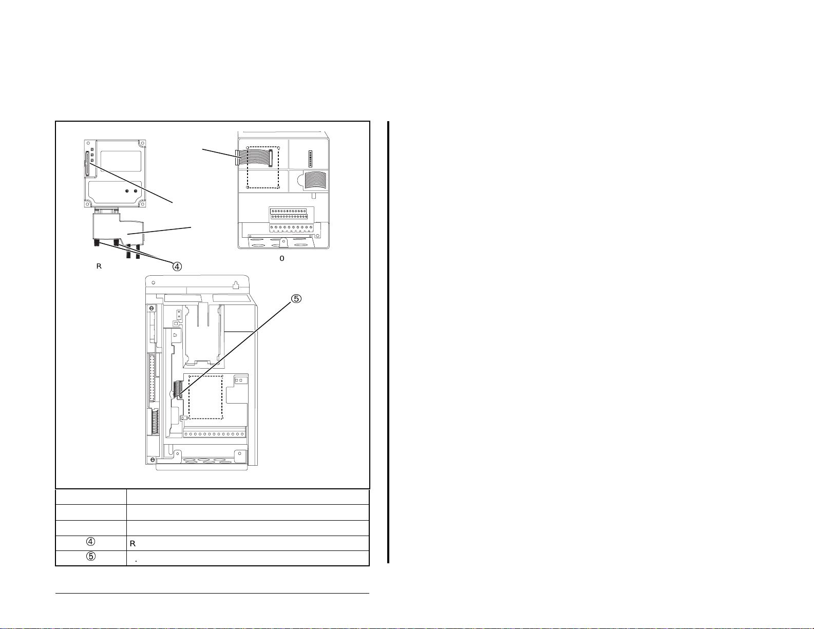
3.5 Connecting the Module to the Drive
Step 1. Remove power from the drive.
Step 2. Use static control precautions.
Step 3. Connect the Internal Interface cable to the DPI po rt on the
drive and then to the DPI connector on the module.
SP600 Drive
PROFIBUS Module
1-20 HP
Installing the PROFIBUS Module
15.24 cm (6 in) Internal Interface cable
DPI connector
PROFIBUS connecto r
Retaining screws
2.54 cm (1 in) Internal Interface cable
Figure 3.5 – DPI Ports and Internal Interface Cables
SP600 AC Drive
Frame 2 and Larger
3-5
Page 22
Step 4. For 1-20 HP SP600 drives, fold the Internal Interface
g
cable behind the module and mount the module on the
drive using the four captive screws. See figure 3.6.
For frame 2 and larger SP600 drives, mount the module
on the drive using the four captive screws to secure and
ground it to the drive.
Important:All screws must be tightened since the module is
grounded through a screw. The recommended
tightening torque is 0.9 N-m (8 in-lb).
Drive
Module
Internal Interface cable
folded behind the module
and in front of the drive.
SP600 Drive
1-20 HP
3-6
SP600 Drive
Frame 2 and Lar
Figure 3.6 – Mounting and Grounding the PROFIBUS Module
er
PROFIBUS Communications Module
Page 23

3.6 Applying Power
ATTENTION:Unpredictabl e ope ration ma y occur if
parameter settings and switch settings are not
!
compatible with your application. Verify that settings
are compatible w ith your application befo re applying
power to the drive. Failure to observe these
precautions could result in sev ere bodil y inj ury or
loss of life.
Step 1. Verify that the module will have a unique address on the
Step 2. Close the door or reinstall the cover on the drive. The
Step 3. Apply power to the drive. The module receives its power
Step 4. If the node address switches are set to “00,” use a
Step 5. Apply power to the master device and other devices on
network. If a new address is needed, reset its switches
(refer to section 3.2, Commissioning the Module).
status indicators can be viewed on the front of the drive
after power has been applied.
from the connected drive. When you apply power to the
product, the status indicators should be green after an
initialization. If the status indicators are red, there is a
problem. Refer to chapter 8, Troubleshooting the
PROFIBUS Module and Network.
configuration tool to set the node address parameters in
the module (refer to chapter 4, Configuring the
PROFIBUS Module).
the network.
Installing the PROFIBUS Module
3-7
Page 24

3-8
PROFIBUS Communications Module
Page 25

CHAPTER 4
Configuring the
PROFIBUS Module
Chapter 4 provides instructions and information for setting the
parameters in the module.
For a complete list of parameters, refer to Appendix B, PROFIBUS
Module Parameters. For defini tio ns of term s in this chap ter, refer to
the Glossary.
4.1 Configuration Tools
The PROFIBUS module st ores p arame ters and othe r info rmatio n in
its own non-volatile memory. Therefore, you must access the
module to view and edi t it s p arameters. Table 4.1 l is ts the tools that
can be used to access the module parameters.
Table 4.1 – Configuration Tools
Tool R efer to:
VS Utilities Software VS Utilities online help
LCD OIM Section 4.2
Configuring the PROFIBUS Module
4-1
Page 26
4.2 Using the LCD OIM to Configure the
Module
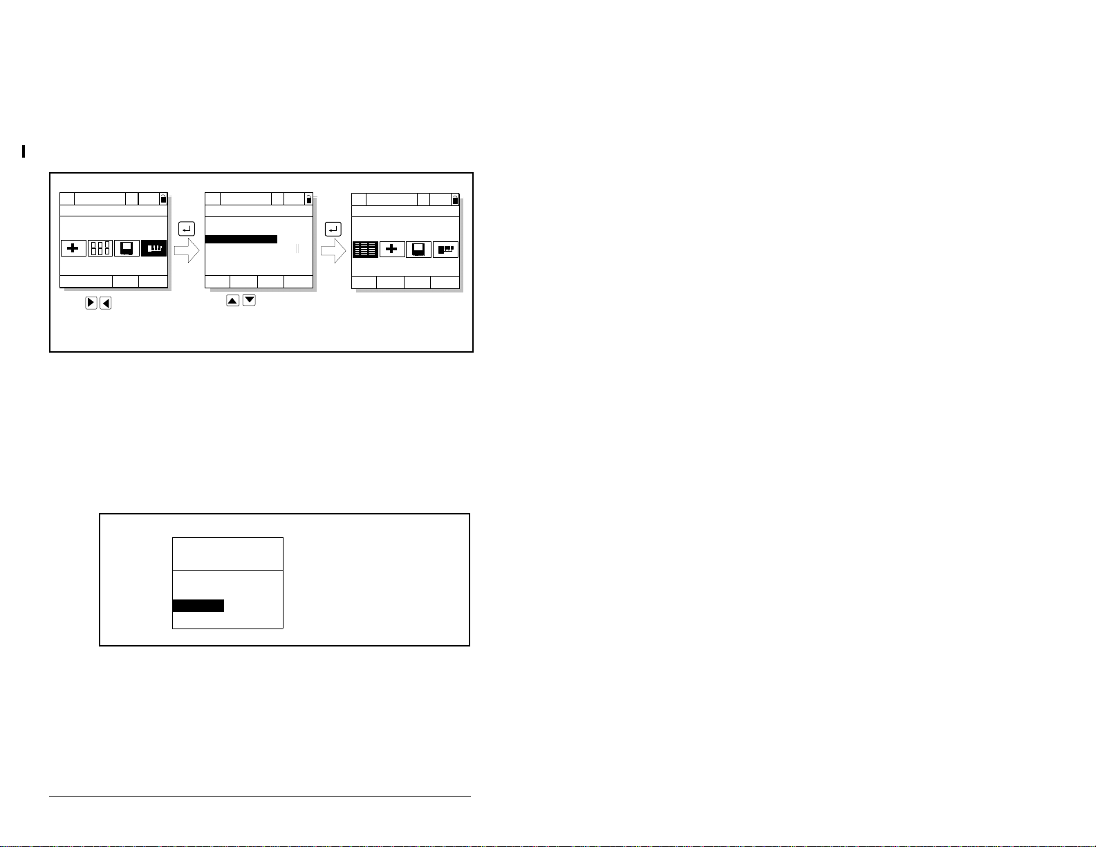
Use the procedure in figure 4.1 to access the parameters on the
PROFIBUS module using the LCD OIM. If you are unfamiliar with
the operation of the LCD OIM, refer to the SP600 AC Drive User
Manual (D2-3485 or D2-3501) for more information.
>>
Stopped
P0: SP600
Main Menu
Device Select
Monitor
Use to highlight
Device Select icon
Auto
Lang
>>
Stopped
P0: SP600
Device: Port 0
SP600
RECOMM-PBUS
Use to select
RECOMM-PBUS.
Auto
Figure 4.1 – Accessing the PROFIBUS Parameters Using the LCD OIM
4.3 Setting the Node Address
If the node address switches are set to “00”, the value of module
parameter 3 (P-DP Addr Cfg) determines the node address.
Step 1. Set the value of parameter 3 (P-DP Addr Cfg) to a unique
node address as shown in figure 4.2.
Port 5 Device
RECOMM-PBUS
Parameter #: 3
P-DP Addr Cfg
01
0 <> 126
Default = 01
>>
Stopped
P5: RECOMM-PBUS
Main Menu
Parameters
Edit the PROFIBUS
parameters using the
same techniques as for
drive parameters.
Auto
4-2
Figure 4.2 – PROFIBUS Node Address Screen on an LCD OIM
Step 2. Reset the module. Refer to section 4.5.2, Resetting the
Module.
PROFIBUS Communications Module
Page 27
4.4 Setting the I/O Configuration
The I/O configuration determines the type of data sent to the drive.
Logic Command/Status, Reference/Feedback, and Datalinks may
be enabled or disabled.
Step 1. Set the bits in module parameter 11 (DPI I/O Config) as
shown in figure 4.3. A “1” enables the I/O. A “0” disables
it. Bit 0 is the right-most bit. In figure 4.3, it is highlighted
and equals “1.”
Port 5 Device
RECOMM-PBUS
Parameter #: 11
DPI I/O Config
xxxxxxxxxxx0000
Cmd/Ref b00
Figure 4.3 – I/O Configuration Screen on an LCD OIM
Bit Description
0 Logic Command/Reference
(Default)
1 Datalink A
2 Datalink B
1
3 Datalink C
4 Datalink D
5 - 16 Not Used
Step 2. If Logic Command/Reference is enabled (default),
configure the parameters in the drive to accept the Logic
Command and Reference from the module. For example,
set Speed Ref A Sel (SP600 drive parameter 90) to
“Network” so that the drive uses the Reference from the
network. Also, verify that Logic Source Sel (drive
parameter 89) is config ured to “Netwo rk” so tha t the d r ive
uses the logic command from the network.
Step 3. If you enabled one or more Datalinks (opt ional), confi gure
parameters in the drive to deter mi ne the sou rce and
destination of dat a in the Data link(s). Also, e nsure that the
PROFIBUS module is the only module using the enabled
Datalink(s).
Step 4. Reset the module. Refer to section 4.5.2, Resetting the
Module.
The module is ready to receive I/O from the master (i.e., scanner).
You must now configure the scanner to recognize and transmit I/O
to the module. Refer to chapter 5, Configuring the PROFIBUS
Scanner, for more information.
Configuring the PROFIBUS Module
4-3
Page 28
4.5 Setting a Fault Action
ATTENTION:Parameter 9 (Comm Flt Action) and
parameter 10 (Id le Fl t Acti on) let you determine the
!
By default, when communications are disrupted (for example, a
cable is disconnected) or the master is idle, the drive responds by
faulting if it is using I/O from the network. You can configure a
different response to communication disruptions using module
parameter 9 (Comm Flt Action) and a different response to an idle
scanner using parameter 10 (Idle Flt Action).
Set the values of parameter 9 (Comm Flt Action) and parameter 10
(Idle Flt Action) to the de sired r esp onses as sho wn in ta ble 4. 2. Se e
figure 4.4 for sample LCD OIM Fault Action screens.
Table 4.2 – Selections for Drive Response to Communication Fault
Value Action Description
0 Fault (default) The drive is faulted and stopped (Default).
1 Stop The drive is stopped, but not faulted.
2 Zero Data The drive is sent 0 for output data after a
3 Hold Last The drive continues in its present st ate after a
4 Send Flt Cfg The drive is sent the data that you set in the
action of the module and connected drive if
communications are disrupted or the scanne r is idle.
By default, these pa rameters fault the driv e. Y ou can
set these param eter s so that the drive continues to
run. Precautions should be taken to en sure that the
settings of these parameters do not create a risk of
injury or equipment damage.
communicat ions disruption. This does not
command a stop.
communicat ions disruption.
fault configuration parameters 13 through 22
(Flt Cfg Logic through Flt Cfg D2 In).
4-4
Port 5 Device
RECOMM-PBUS
Parameter #: 9
Comm Flt Action
0
Fault
Figure 4.4 – Fault Action Screens on an LCD OIM
Changes to these par ameters t ake ef fect immedia tely. A reset is not
required.
Port 5 Devi ce
RECOMM-PBUS
Parameter #: 10
Idle Flt Action
0
Fault
PROFIBUS Communications Module
Page 29

4.5.1 Setting the Fault Configuration Parameters
If you set module parameter 9 (Comm Flt Action) or module
parameter 10 (Idle Flt Action) to “Send Flt Cfg,” the values in the
parameters shown in table 4.3 are sent to the drive after a
communications fault and/or idle fault occurs. You must set these
parameters to values required by your application.
Table 4.3 – Fault Configuration Parameters
Number Name Description
13 Flt Cfg Logic A 16-bit value sent to the drive
14 Flt Cfg Ref A 32-bit value (0 to 429496 7295)
15 - 22 Flt Cfg x1 In or
Flt Cfg x2 In
Changes to these par ameters t ake ef fect immed iately. A reset is not
required.
for Logic Command
sent to the drive as a Reference
or Datalink.
Important: If the drive uses a
16-bit Reference or 16-bit
Datalinks, the most significant
word of the value must be set to
zero (0) or a fault will occur.
Configuring the PROFIBUS Module
4-5
Page 30
4.5.2 Resetting the Module
Changes to swit ch settin gs or some modul e paramet ers req uire that
you reset the module before the new settings take effect. You can
reset the module by cycling power to the drive or by using module
parameter 8 (Reset Module).
ATTENTION: If the module is transmitting control
I/O to the drive, the drive may fault when you reset
!
Set parameter 8 (Reset Module) to “Reset Module.” See figure 4.5.
the module. Determi ne h ow yo ur dri ve w ill respond
before resetting a connected module. Failure to
observe this precaution could result in bodily injury
or damage to equipment.
Port 5 Device
RECOMM-PBUS
Parameter #: 8
Reset Module
1
Reset Module
Figure 4.5 – Reset Screen on an LCD OIM
When you enter 1 (“Reset Module”), the module will be
immediatel y reset. When you enter 2 (“Set Defaults”), the module
will set all module parameters to their factory-default settings. The
value of this parameter will be restored to 0 (“Ready”) after the
module is reset.
Value Description
0 Ready (Default)
1 Reset Module
2 Set Defaults
4-6
PROFIBUS Communications Module
Page 31

4.6 Viewing the Module Configuration
The parameters in table 4.4 provide information about how the
module is configured. You can view these parameters at any time.
Table 4.4 – Module Configuration Status Parameters
Number Name Description
01 DPI Port The port on the drive to which the module is
connected. Usually, it is port 5.
02 DPI Data
Rate
04 P-DP Addr
Actual
06 Ref/Fdbk
Size
07 Datalink
Size
12 DPI I/O
Active
The data rate used by DPI in the drive. It is set in the
drive, and the module detects it.
The node address used by the module. This will be
one of the following values:
• The address set by the rotary switches.
• The value of module parameter 3 (P-DP Addr Cfg)
if the switches have been disabled.
• An old address of the switches or p arame ter if they
have been changed and the module has not been
reset.
The size of the Reference/Feedback. It will either be
16 bits or 32 bits. It is set in the drive and the module
automatically uses the correct size.
The size of the Datalink word. It will either be 16 bits
or 32 bits. It is set in the drive and the module
automatically uses the correct size.
The Reference/Feedback and Datalinks are used by
the module. This value is the same as module
parameter 11 (DPI I/O Config) unless the parameter
was changed and the module was not reset.
Bit Definitions
0 = Cmd/Ref
1 = Datalink A
2 = Datalink B
3 = Datalink C
4 = Datalink D
5 = Not Used
6 = Not Used
7 = Not Used
Default
Bit
01234576
10000xxx
Configuring the PROFIBUS Module
4-7
Page 32

4-8
PROFIBUS Communications Module
Page 33

CHAPTER 5
Configuring the
PROFIBUS Scanner
A scanner is a separate module of a multi-module controller or a
built-in component of a single-module controller that provides
communication with a module connected to a network.
PROFIBUS scanners are available from several manufacturers,
including SST. SST PROFIBUS scanners come with a soft ware to ol
for configuring the scanner (see figure 5.1).
Device
Library
window
Online
Browse
window
Network
Configuration
[001]_RECOMM_PBUS
[002]_RECOMM_PBUS
Figure 5.1 – SST PROFIBUS Configuration Software Tool
Chapter 4 provides instructions on how to utilize the SST
PROFIBUS configuration software tool to:
window
• Install the RECOMM-PBUS GSD file in the software tool library.
• Configure the SST-PFB-SLC PROFIBUS scanner.
Important:The configuration of other manufacturer’s sc anners may
differ significantly from this example. Please refer to
your scanner manufacturer’s documentation.
Configuring the PROFIBUS Scanner
5-1
Page 34

5.1 Configuring a Simple Network:
An Example
In this example, we will be configuring two SP600 dr ives to be
Station 1 and Station 2 on a PROFIBUS network. This will be the
configuration used throughout the manual, including the ladder
examples. Apart fro m the no de add ress a nd scanne r ma pping , they
will have identical configurations. This chapter describes the steps
to configure a simple network like the network in figure 5.2.
COMM LED
Scanner
Station 0
SP600 Drive
Station 1 Station 2
Figure 5.2 – Sample PROFIBUS Network
SYS LED
Config Port
Front Label
Profibus Port
SP600 Drive
5.1.1 Installing the RECOMM-PBUS GSD File in the
Software Tool Library
GSD files are used by software tools to configure the network, in
other words, to map and define the I/O in a PROFIBUS scanner. A
GSD file is required for each type of module on the network.
5-2
For example: The RECOMM-PBUS GSD file is “Rele0573.gsd” and
a copy of the file is provided on a floppy disk with each
RECOMM-PBUS PROFIBUS module. The file can also be
downloaded from the Internet by going to: www.reliance.com.
PROFIBUS Communications Modul e
Page 35

Follow the steps outlined below only whe n a n ew G SD fil e ne eds to
be added to the SST PROFIBUS Configuration Software Tool.
Typically, this is only done once, after the software tool is initially
installed or if configuring a RECOMM-PBUS on the network for the
very first time with this software tool.
The software too l co me s w it h standard data file s as shown in figure
5.3. Additional data fil es, such as the RECO MM-PBUS GSD file, will
need to be added to configure the RECOMM-PBUS in the scanner.
Figure 5.3 – Standard Data Files
Step 1. Click on the “New Device” icon to add GSD files to
the software library tool.
Step 2. An “Add PROFIBUS devices” applet window will appear
(see figure 5.4). Prompts for the location of the
PROFIBUS data files to be added to the library will follow.
Figure 5.4 – Add PROFIBUS Devices Applet Window
Configuring the PROFIBUS Scanner
5-3
Page 36

Step 3. Find the directory location of the data file(s) you wish to
add (typically, the source location is a floppy disk in drive
A:). “Rele0573.gsd” is the GSD file for the
RECOMM-PBU S as shown in figure 5.5.
Rele0573.gsd
Rele0573.gsd
Figure 5.5 – Adding the GSD File for the RECOMM-PBUS
”
Step 4. Select “Rele0573.gsd
pen.
O
for the RECOMM-PBUS and click
Step 5. Click on the (+) sign of the Slaves folder as shown in
figure 5.6.
5-4
Reliance Electric
RECOMM-PBUS [V1.001.01]
Figure 5.6 – Masters/Slaves Library Window
The software tool will automatically create a Reliance Electric
sub-folder (in the Slaves folder) if it does not already exist. The
RECOMM-PBUS is now shown in the library and the software tool
is now ready to configure a RECOMM-PBUS on a PROFIBUS
network.
PROFIBUS Communications Modul e
Page 37

5.2 Configuring the SST-PFB-SLC
PROFIBUS Sc an ner
The following steps are performed to configure the SST-PFB-SLC
scanner using the SST PROFIBUS Configuration Software Tool. In
our example, the PROFIBUS network will consist of a SLC master
and two SP600 drives. The ladder examples in the manual will use
the following configuration:
• Logic Command / Status and Reference / Feedback enabled
• Datalink A enabled
• Datalink B enabled
• Datalink C enabled
• Datalink D enabled
• Parameter Access enabled (used to perform explicit messaging)
The SLC processor must be in Program mode to configure the
scanner.
Step 1. Click on the (+) sign of the Masters folder in the Library
Step 2. Click on the (+) sign of the Slaves folder in the Library
Step 3. Double-click the SST-PFB-SLC MASTER in the Masters
window to open the SST sub-fold er . Avai lable DP mast ers
are displayed in this sub-folder.
window and the Reliance Electric sub-folder to display
the available DP slaves or the RECOMM-PBUS slave.
Refer to figure 5.7.
folder in the Library window to add the scanner to the
network.
Configuring the PROFIBUS Scanner
5-5
Page 38

Step 4. A user-defined Name and Description can be given to
the scanner. In our example, the scanner will be S
tation 0
on the network, as shown i n figure 5.7.
Figure 5.7 – SST-SST-PFB-SLC Master (General) Dialog Box
Step 5. Click on the Parameters tab to view the Scan Cycle
Times.
In our example, use the default settings as shown in
figure 5.8.
Figure 5.8 – Scan Cycle Times Dialog Box
Connection and Baud Rate s etting s con figure h ow the s oft ware to ol
will communicate with the CONFIG RS232 port on the scanner.
Step 6. Click on the COM Port tab.
5-6
PROFIBUS Communications Modul e
Page 39

Step 7. Accept the settings in our example (COM1 on the PC at
115200 bps baud rate), as shown in figure 5.9.
Figure 5.9 – COM Port Default Settings
Step 8. The scanner will appear in the network window as shown
in figure 5.10. Double-click on the scanner in the network
window.
Figure 5.10 – Scanner Network Window
Step 9. Double-click on the RECOMM-PBUS listed in the
Reliance Electric library folder. A user-defined N
escription can be given to this RECOMM-PBUS.
D
In our example, this device will be S
network. Other stations may be chosen by using the
arrow to display a drop-down list in the S
Reliance Electric RECOMM-PBUS
Reliance Electric RECOMM-PBUS
Figure 5.11 – Reliance Electric Library Dialog Window
Configuring the PROFIBUS Scanner
ame and
tation 1 on the
tation window.
C:\DLINK32\COMMON\PBC\gsd\Rele0573.gsd
RECOMM-PBUS
5-7
Page 40

Logic Command / Status, Reference / Feedback, Datalinks and
Parameter Access (explicit messaging) modules are added using
the Modules tab.
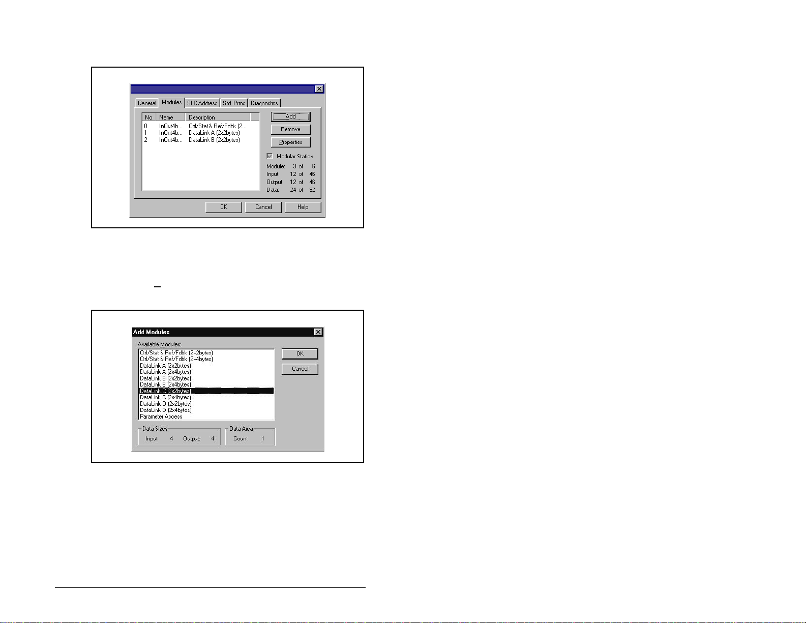
Step 10. Click on the Modules tab. Click A
dd to view the choice of
modules.
Reliance Electric RECOMM-PBUS
Figure 5.12 – RECOMM-PBUS Modules Tab
In our example, Station 1 will be controlled using Logic
Command / Status and Reference / Feedback. The
SP600 drive uses 16-bit Reference / Feedback (2 bytes).
Step 11. Select “Ctrl/Stat & Ref/Fdbk (2+2bytes)” from the
“Available M odu le s” l is t a s sho wn i n figure 5.13. Click OK.
5-8
Figure 5.13 – Available Modules: Ctrl/Stat & Ref/Fdbk (2x2Bytes) Window
PROFIBUS Communications Modul e
Page 41

Step 12. The “Ctrl/Stat & Ref/Fdbk” (2+2 bytes) module has now
been added as shown in figure 5.14.
Reliance Electric RECOMM-PBUS
Figure 5.14 – Modules: Ctrl/Stat & Ref/Fdbk Viewing Window
Station 1 will be co nfi gure d to us e Datalinks A1 and A2. The SP60 0
drive uses 16-bit Datalinks.
Step 13. Click A
dd to continue adding mod ules. Se lect “D at alink A
(2x2bytes)” and click OK.
Figure 5.15 – Add Modules: Datalink A Selection Window
Configuring the PROFIBUS Scanner
5-9
Page 42

Step 14. The “Datalink A” module has now been added as shown
in figure 5.16.
Reliance Electric RECOMM-PBUS
Figure 5.16 – Modules: Datalink A Viewing Window
Station 1 will also be configured to use Datalinks B1 and B2. The
SP600 drive uses 16-bit Datalinks.
Step 15. Click A
dd to continue adding mod ules. Se lect “D at alink B
(2x2 bytes)” and click OK.
5-10
Figure 5.17 – Add Modules: Datalink B Selection Window
PROFIBUS Communications Modul e
Page 43
Step 16. The “Datalink B” module has now been added as shown
in figure 5.18.
Reliance Electric RECOMM-PBUS
Figure 5.18 – Modules: Datalink B Viewing Window
Station 1 will also be configured to use Datalinks C1 and C2. The
SP600 drive uses 16-bit Datalinks.
Step 17. Click A
dd to continue ad ding modul es. Sel ect “D at alink C
(2x2bytes)” as shown in figure 5.19 and click OK.
Figure 5.19 – Add Modules: Datalink C Selection Window
Configuring the PROFIBUS Scanner
5-11
Page 44

Step 18. The “Datalink C” module has now been added as shown
in figure 5.20.
Reliance Electric RECOMM-PBUS
Figure 5.20 – Modules: Datalink C Viewing Window
Station 1 will also be configured to use Datalinks D1 and D2.
The SP600 drive uses 16-bit Datalinks.
Step 19. Click A
dd to continue ad ding modul es. Sel ect “D at alink D
(2x2bytes)” as shown in figure 5.21 and click OK.
5-12
Figure 5.21 – Add Modules: Datalink D Selection Window
The “Datalink D” module has now been added.
Station 1 will also be configured to use Parameter Access for
explicit messaging.
PROFIBUS Communications Modul e
Page 45
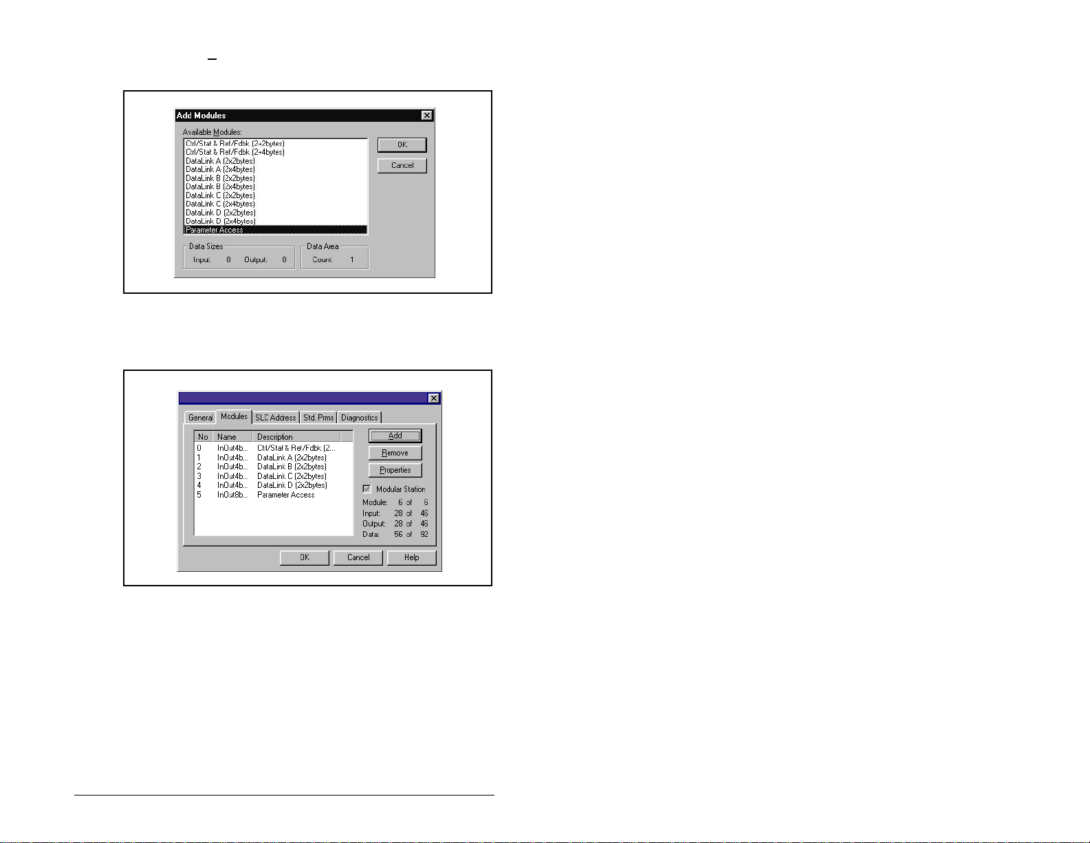
Step 20. Click Add to continue adding m odules. Select “Param eter
Access” as shown in figure 5.22 and click OK.
Figure 5.22 – Add Modules: Parameter Access Selection Window
Step 21. The “Paramete r Acc es s” mod ul e ha s n ow be en a dd ed a s
shown in figure 5.23.
Reliance Electric RECOMM-PBUS
Figure 5.23 – Modules: Parameter Access Viewing Window
Settings can be chosen to map Station mod ule s to S LC addre ss es .
In our example, M1/M0 files are used for Input / Output.
Note that the Reference/Feedback (Ctrl/Stat & Ref/Fdbk) start at
word 0.
Configuring the PROFIBUS Scanner
5-13
Page 46
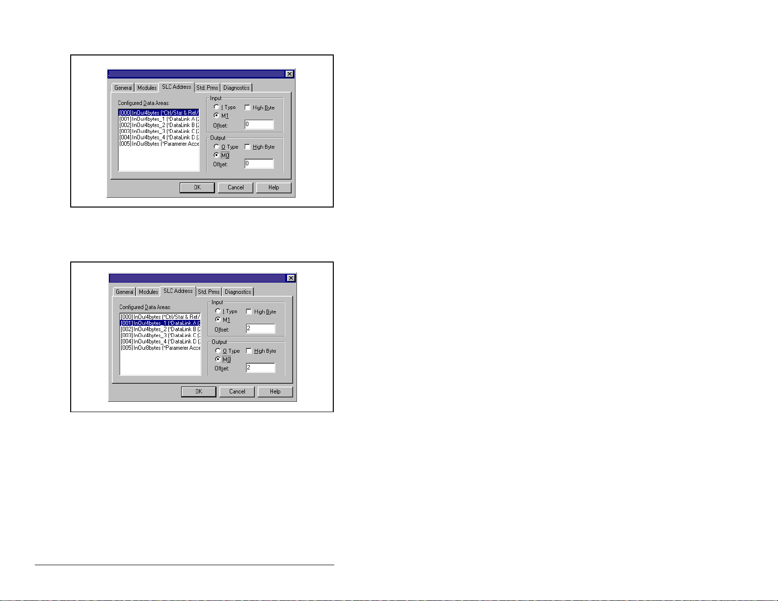
Step 22. Click on the SLC Address tab as shown in figure 5.24.
Reliance Electric RECOMM-PBUS
Figure 5.24 – SLC Address: M1/M0 (Ctrl/Stat & Ref/Fdbk)
Step 23. Datalink A is at word 2 in the M1/M0 files as shown in
figure 5.25.
Reliance Electric RECOMM-PBUS
Figure 5.25 – SLC Address: M1/M0 (Datalink A)
5-14
PROFIBUS Communications Modul e
Page 47
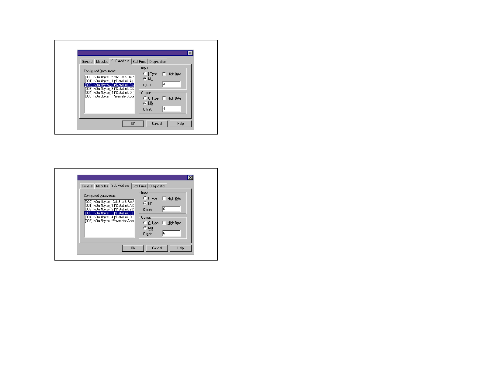
Step 24. Datalink B is at word 4 in the M1/M0 files as shown in
figure 5.26.
Reliance Electric RECOMM-PBUS
Figure 5.26 – SLC Address: M1/M0 (Datalink B)
Step 25. Datalink C is at word 6 in the M1/M0 files as shown in
figure 5.27.
Reliance Electric RECOMM-PBUS
Figure 5.27 – SLC Address: M1/M0 (Datalink C)
Configuring the PROFIBUS Scanner
5-15
Page 48

Step 26. Datalink D is at word 8 in the M1/M0 files as shown in
figure 5.28.
Reliance Electric RECOMM-PBUS
Figure 5.28 – SLC Address: M1/M0 (Datalink D)
Step 27. Parameter Access starts at word 10 in the M1/M0 files.
Note that Parameter Access uses 4 words (10-13). See
figure 5.29. Click OK when finished.
Reliance Electric RECOMM-PBUS
Figure 5.29 – SLC Address M1/M0 (Parameter Access)
Step 28. Station 1 is now displayed in the network window. See
figure 5.30.
[001]_RECOMM_PBUS (**)
5-16
Figure 5.30 – Station 1 Network Window
PROFIBUS Communications Modul e
Page 49

Step 29. Station 1 is configured as follows:
Module M 1/M0 Word
Ctrl/Stat & Ref Fdbk 0
Datalink A 2
Datalink B 4
Datalink C 6
Datalink D 8
Parameter Access 10
Note that Station 1 occupies 14 words (0-13).
Step 30. The same steps for configuring Station 1 will be used for
configuring Station 2. Refer to previous steps (starting at
step 9,) for Configuring the SST -PFB-SLC PROFIBUS
Scanner-Station 2. (See figure 5.31.)
[001]_RECOMM_PBUS(**)
[002]_RECOMM_PBUS(**)
Figure 5.31 – Station 2 Network Window
Station 2 is configured as follows:
Module M1/M0 Offset
Ctrl/Stat & Ref Fdbk 14
Datalink A 16
Datalink B 18
Datalink C 20
Datalink D 22
Parameter Access 24
Note that Station 2 occupies 14 words (14-27).
Step 31. Use the null modem cable that came with the scanner to
connect COM1 on the PC and the CONFIG RS232 port
on the scanner.
Configuring the PROFIBUS Scanner
5-17
Page 50

Important: The processor needs to be in program mode before
proceeding.
Step 32. Right-click on the scanner in the network window and
select “Connect”. Th en ri gh t-cl ic k a gai n on the scanner in
the network window and select “Load Configuration”. If a
minimum cycle time attention window pops up, click OK
to continue. After the configuration has been loaded into
the scanner , “Confi gured Program” will be di splayed in the
message window (see figure 5.32).
[001]_RECOMM_PBUS(**)
[002]_RECOMM_PBUS(**)
Figure 5.32 – Network Window Scanner Selection
Step 33. Click F
ame. The config urat ion o f th e scanner is now c om pl ete .
N
Note that cycling power to the scanner is recommended.
See figure 5.33.
ile and Save As from the tool bar, as a unique File
Figure 5.33 – Save As Dialog Window
5-18
PROFIBUS Communications Modul e
Page 51

Summary of the sample scanner configuration:
M0 / M1 Addressing
Module
Logic Command / Status 0 14
Referenc e / Feedback 1 15
Datalink A1 2 16
Datalink A2 3 17
Datalink B1 4 18
Datalink B2 5 19
Datalink C1 6 20
Datalink C2 7 21
Datalink D1 8 22
Datalink D2 9 23
Parameter Access 10-13 24-27
Station 1 Station 2
5.3 GSD Diagnostic Messages
In the case of invalid GSD module configuration, the peripheral will
send one of the messages shown in table 5.1.
Table 5.1 – GSD Diagnostic Messages
Fault Description
No Ctrl/Stat & Ref/Fdbk The Ctrl/Stat & Ref/Fdbk module
Module used more than
once
Not supported module An unrecogni zed modu le has bee n
Configuring the PROFIBUS Scanner
must always be used and placed
first in the configuration.
A GSD module has been used
more than once.
used in the configuration.
5-19
Page 52

5-20
PROFIBUS Communications Modul e
Page 53

CHAPTER 6
Using I/O Messaging
Chapter 6 provides information and examples that explain how to
use I/O Messaging to control an SP600 drive.
ATTENTION:The examples in this publication are
intended solely for p urpose s of ex ample . There a re
!
6.1 About I/O Messaging
I/O messaging is used t o trans fer the d ata w hich cont rols t he SP600
drive and sets its Reference. I/O can also be used to transfer data
to and from Datalinks in SP600 drives.
many variables and requirements with any
application. Roc kwell Autom ation does no t assume
responsibility or liability (to include intellectual
property liability) for actual use of the examples
shown in this publication. Failure to observe this
precaution could result in bodily inju ry or damage to
equipment.
The PROFIBUS module provides options for configuring and using
I/O, including the size of the I/O, which can be configured by
enabling or disabl ing the Lo gic Comma nd/Refere nce and Dat alink s.
Chapter 4, Configuring the PROFIBUS Module, and chapter 5,
Configuring the PROFIBUS Scanner, discuss how to configure the
module and scanner on the network for these options. The Glossary
defines the dif fe rent options. This chap ter d isc us s es h ow to use I/O
after you have configured the module and scanner.
6.2 Understanding the I/O Image
The terms input and output are defined from scanner’s point of
view. Therefore, Output I/O is data that is output from the scanner
and consumed by the PROFIBUS module. I nput dat a is status data
that is produced by the module and consumed as input by the
scanner.
Using I/O Messaging
6-1
Page 54

The I/O image table will vary based on the following:
• Size (either 16-bit o r 32-bit ) of t he Refere nce/Fe edbac k word an d
Datalink words used by the drive.
• Configuration of parameter 11 (DPI I/O Config). If not all I/O is
enabled, the image table is truncated. The image table always
uses consecutive words starting at word 0.
Figure 6.1 illustrates an exampl e of an I/O image wi th 16- bit w ord s.
Controller
PROFIBUS
Scanner
Output
Image
(Write)
Input
Image
(Read)
Module SP600 Drive
Word and I/O
0 Logic Command
1 Reference
2 Datalink In A1
3 Datalink In A2
4 Datalink In B1
5 Datalink In B2
6 Datalink In C1
7 Datalink In C2
8 Datalink In D1
9 Datalink In D2
10 Parameter Access Word 1
11 Parameter Access Word 2
12 Parameter Access Word 3
13 Parameter Access Word 4
0 Logic Status
1 Feedback
2 Datalink Out A1
3 Datalink Out A2
4 Datalink Out B1
5 Datalink Out B2
6 Datalink Out C1
7 Datalink Out C2
8 Datalink Out D1
9 Datalink Out D2
10 Parameter Access Word 1
11 Parameter Access Word 2
12 Parameter Access Word 3
13 Parameter Access Word 4
DPI
Logic Command
Reference
Data In A1
Data In A2
Data In B1
Data In B2
Data In C1
Data In C2
Data In D1
Data In D2
Message
Handler
Logic Status
Feedback
Data Out A1
Data Out A2
Data Out B1
Data Out B2
Data Out C1
Data Out C2
Data Out D1
Data Out D2
Message
Handler
6-2
Figure 6.1 – Sample I/O Image with All I/O Enabled
PROFIBUS Communications Modul e
Page 55

An image that uses 32-bit words f or Referen ce and Dat ali nks wou ld
change the I/O image in figure 6.1 as follows:
Word I/O Word I/O
0Logic
7 - 10 Datalink B
Command/Status
1 - 2 Reference/
11 - 14 Datalink C
Feedback
3 - 6 Datalink A 15 - 18 Datalink D
Figure 6.2 illustrates an example of an I/O image that does not use
all of the I/O data. Only the Logic Command/Reference and
Datalink B are enabled. In this example, the Reference is a 32-bit
word, and Datalinks are 16-bit words.
PROFIBUS
Controller Scanner Module SP600 Drive
Word and I/O
Output
Image
(Write)
Input
Image
(Read)
LSW = Least Significant Word (Bits 15 - 0)
MSW = Most Significant Word (Bit s 31 - 16)
0 Logic Command
1 Reference (LSW)
2 Reference (MSW)
3 Datalink In B1
4 Datalink In B2
0 Logic Status
1 Feedback (LSW)
2 Feedback (MSW)
3 Datalink Out B1
4 Datalink Out B2
DPI
Logic Command
Reference
Data In A1
Data In A2
Data In B1
Data In B2
Data In C1
Data In C2
Data In D1
Data In D2
Logic Status
Feedback
Data Out A1
Data Out A2
Data Out B1
Data Out B2
Data Out C1
Data Out C2
Data Out D1
Data Out D2
Figure 6.2 – Sample I/O Image with Only Logic/Reference and Datalink B Enabled
Using I/O Messaging
6-3
Page 56

6.3 Using Logic Command/Status
When enabled, the Logic Command/Status word is always word 0
in the I/O image. The Logic Command is a 16-bit word of control
produced by the scanner and consumed by the module. The Logic
Status is a 16-bit word of status produced by the module and
consumed by the scanner.
This manual contains the bit definitions for compatible products
available at the time of publication in Appendix C, Logic Command/
Status Words. For other products, refer to their documentation.
6.4 Using Reference/Feedback
When enabled, Ref erence/Fee dback alw ays begin s at word 1 in t he
I/O image. The Reference (16 bits or 32 bits) is produced by the
controller and consumed by the module. The Feedback (16 bits or
32 bits) is prod uc ed by the module and co nsu me d by th e co ntro ller.
The size of the Reference/F eed back is dete rmi ned by the drive and
displayed in module param eter 6 (Ref/Fdbk Size).
Size Valid Values In I/O Image Example
16-bit -32768 to 32767 Word 1 Figure 6.1
32-bit -2147483648 to
2147483647
Word 1 and
Word 2
Figure 6.2
6.5 Using Datalinks
A Datalink is a mec hanis m use d by SP600 drives to transf er da ta to
and from the controller. Datalinks allow a parameter value to be
changed without using an Explicit Message.
When enabled (optional), each Datalink consumes either two 16 or
32-bit words in both the input and output image depending on its
size. The size of Datalinks (16-bit words or 32-bit words) is
determined by the drive and displayed in module parameter 7
(Datalink Size) in the module.
6.5.1 Rules for Using Datalinks
•
Each set of Datalink parameters in an SP600 drive can be used
by only one module. If more than one module is connected to a
single drive, multiple modules must not try to use the same
Datalink.
6-4
PROFIBUS Communications Modul e
Page 57

• Parameter settings in the drive determine the data passed
through the Datalink mechanism. Refer to the documentation for
your drive.
• When you use a Datalink to change a value, the value is not
written to the Non-Volatile Storage (NVS). The value is stored in
volatile memory and lost when the drive loses power.
6.5.2 32-Bit Parameters using 16-Bit Datalinks
To read (and/or write) a 32-bit parameter using 16-bit Datalinks,
typically both Datalinks (A,B,C,D) are set to the 32-bit parameter.
For example, to read Elapsed MWh (SP600 drive parameter 9),
both Datalink A1 and A2 are set to “9.” Datalink A1 will contain the
least significant word (LSW) and Datalink A2 the most significant
word (MSW). In this example, the parameter 9 value of 5.8 MWh is
read as a “58” in Datalink A1.
Most/Least
Datalink
A1 LSW 9 58
A2 MSW 9 0
Regardless of the Datalink combination, x1 will always contain the
LSW and x2 will alway s cont ain the M SW . I n the follo wing exam ples
Power Up Marker (drive parameter 242) contains a value of
88.4541 ho urs.
Significant Word Parameter Data (decimal)
Datalink
A1 LSW 242 32573
A2 - Not Used - 0 0
Datalink
A1 - Not Used - 0 0
A2 MSW 242 13
Datalink
A2 MSW 242 13
B1 LSW 242 32573
32-bit data is stored in binary as follows:
MSW
LSW
Using I/O Messaging
Most/Least
Significant Word Parameter Data (decimal)
Most/Least
Significant Word Parameter Data (decimal)
Most/Least
Significant Word Parameter Data (decimal)
31
through 2
2
15
through 2
2
16
0
6-5
Page 58

Example:
Power Up Marker (242) = 88.4541 hours
MSW = 13
LSW = 32573
851968 + 32573 = 884541
decimal
= 1101
= 219 + 218 + 216 = 851968
binary
6.6 Sample SLC Ladder Log ic Program
The PROFIBUS sample program uses an SLC processor with an
SST PROFIBUS scanner (SST-PFB-SLC) in the first s lot of the ra ck
and will work with SP600 drives.
Function of the Sample Program
The program is written for two drives on the network and
demonstrates the use of the following:
• Logic Command / Reference
• Logic Status / Feedback
• Datalinks
• Parameter Access (covered in chapter 7)
Module Settings
The Node Address switch settings on the PROFIBUS modules are
set to:
• “1” for Station 1
• “2” for Station 2
6-6
PROFIBUS Communications Modul e
Page 59

Parameter Settings
Table 6.1 – Parameter Settings for Sample SLC Program
Device Parameter Name Value Description
90 Speed Ref A Sel 22 ‘DPI Port 5’ (RECOMM-PBUS)
300 Data In A1 140 Points to Accel Time 1 (140)
301 Data In A2 142 Points to Decel Time 1 (142)
302 Data In B1 100 Points to Jog Speed (100)
303 Data In B2 155 Points to Stop Mode A (155)
304 Data In C1 101 Points to Preset Speed 1 (101)
305 Data In C2 102 Points to Preset Speed 2 (102)
306 Data In D1 103 Points to Preset Speed 3 (103)
SP600
RECOMM-PBUS 11 DPI I/O Config xxx1 1111 Enables Cmd/Ref, Datalinks A-D
307 Data In D2 104 Points to Preset Speed 4 (104)
310 Data Out A1 140 Points to Accel Time 1 (140)
311 Data Out A2 142 Points to Decel Time 1 (142)
312 Data Out B1 100 Points to Jog Speed (100)
313 Data Out B2 155 Points to Stop Mode A (155)
314 Data Out C1 101 Points to Preset Speed 1 (101)
315 Data Out C2 102 Points to Preset Speed 2 (102)
316 Data Out D1 103 Points to Preset Speed 3 (103)
317 Data Out D2 104 Points to Preset Speed 4 (104)
Scanner Settings
An SST-PFB-SLC scanner is in slot 1 of the SLC rack and
configured as Station 0. The Advanced I/O Configuration is set up
as shown in figure 6.3.
The two PROFIBUS modules are set up as Station 1 and Station 2,
and are configured as 14 word s in put & output each. See chapter 5.
Using I/O Messaging
Figure 6.3 – Advanced I/O Configuration
6-7
Page 60

SLC Data Table
Read Data
File N10: contains the actual read data that can be used elsewhere
in the ladder program.
Station 1
Address
N10:0 N10:14 Logic Status
N10:1 N10:15 Feedback
N10:2 N10:16 Datalink A1
N10:3 N10:17 Datalink A2
N10:4 N10:18 Datalink B1
N10:5 N10:19 Datalink B2
N10:6 N10:20 Datalink C1
N10:7 N10:21 Datalink C2
N10:8 N10:22 Datalink D1
N10:9 N10:23 Datalink D2
N10:10 N10:24 Parameter Access Word 1
N10:11 N10:25 Parameter Access Word 2
N10:12 N10:26 Parameter Access Word 3
N10:13 N10:27 Parameter Access Word 4
Station 2
Address Function
Write Data
The PROFIBUS scanner is configured for 28 bytes (14 words) of
outputs for each drive. Two drives require 48 bytes (28 words).
Station 1
Address
N20:0 N20:14 Logic Command
N20:1 N20:15 Reference
N20:2 N20:16 Datalink A1
N20:3 N20:17 Datalink A2
N20:4 N20:18 Datalink B1
N20:5 N20:19 Datalink B2
N20:6 N20:20 Datalink C1
N20:7 N20:21 Datalink C2
N20:8 N20:22 Datalink D1
N20:9 N20:23 Datalink D2
N20:10 N20:24 Parameter Access Word 1
N20:11 N20:25 Parameter Access Word 2
N20:12 N20:26 Parameter Access Word 3
N20:13 N20:27 Parameter Access Word 4
Station 2
Address Function
6-8
PROFIBUS Communications Modul e
Page 61

Logic Command/St atus Words
The examples in section s 6.7 and 6.8 use the Log ic Command word
and Logic Status word for SP600 drives. Refer to Appendix C, Logic
Command/Status Words, for m ore info rma tion . The defi nit ion of the
bits in these words may vary if you are using a different DPI Host
product. Refer to the documentation for your Host product.
Using I/O Messaging
6-9
Page 62

6.7 Sample SLC Ladder Log ic - Main
Program
This sample program is for a PROFIBUS demonstration using a SLC 5/05 processor with an SST Profibus scanner
(SST-PFB-SLC) in the first slot of the rack. The program is written for (2) drives on the network:
Station 1 PowerFlex 70 Tabletop demo with 20-COMM-P
SP600 Tabletop demo with RECOMM-PBUS
Station 2 PowerFlex 70 Tabletop demo with 20-COMM-P
SP600 Tabletop demo with RECOMM-PBUS
The sample program demonstrates using Logic Command / Reference, Logic Status / Feedback, Datalinks, and Parameter
Access using the Parameter Protocol.
On power up, zero out the transmit buffer to the Scanner.
First Pass
0000
0001
S:1
15
Automatically have the SST-PFB-SLC scanner's watchdog period track that of the SLC processor (recommended per SST user
manual)
FLL
FLL
Fill File
Source 0
Dest #N20:0
Length 28
SST Scanner
Write Data
Word 0
MOV
MOV
Move
Source S:3
2562<
Dest M0:1.4011
?<
The Scanner is configured for 28 bytes (14 words) of inputs for each drive. Two drives require 48 bytes (28 words).
Read the drives data from the Profibus scanner.
0002
Figure 6.4 – Sample SLC Ladder Logic - Main Program
6-10
PROFIBUS Communications Modul e
SST Scanner
Read Data
Word #0
COP
COP
Copy File
Source #M1:1.0
Dest #N9:0
Length 28
Page 63

PROFIBUS scanners vary from manufacturer to manufacturer in how the bytes are ordered in a word. For example, some PROFIBUS
scanners operate with high & low bytes swapped (the value "1234" is represented as "3412"). The READ data is copied into
N10: and the bytes are reversed in the SWP instruction below so a value such as "3412" is viewed as "1234".
Station 1
Logic Status
COP
COP
0003
File N10: contains the actual read data that can be used elsewhere in the ladder program.
Station 1 Station 2 Description
M1:1.0 (N10:0) M1:1.14 (N10:14) Logic Status
M1:1.1 (N10:1) M1:1.15 (N10:15) Speed Feedback
M1:1.2 (N10:2) M1:1.16 (N10:16) Datalink A1
M1:1.3 (N10:3) M1:1.17 (N10:17) Datalink A2
M1:1.4 (N10:4) M1:1.18 (N10:18) Datalink B1
M1:1.5 (N10:5) M1:1.19 (N10:19) Datalink B2
M1:1.6 (N10:6) M1:1.20 (N10:20) Datalink C1
M1:1.7 (N10:7) M1:1.21 (N10:21) Datalink C2
M1:1.8 (N10:8) M1:1.22 (N10:22) Datalink D1
M1:1.9 (N10:9) M1:1.23 (N10:23) Datalink D2
M1:1.10 (N10:10) M1:1.24 (N10:24) Parameter Protocol Word #1
M1:1.11 (N10:11) M1:1.25 (N10:25) Parameter Protocol Word #2
M1:1.12 (N10:12) M1:1.26 (N10:26) Parameter Protocol Word #3
M1:1.13 (N10:13) M1:1.27 (N10:27) Parameter Protocol Word #4
0004
Copy File
Source #N9:0
Dest #N10:0
Length 28
Station 1
Logic Status
SWP
SWP
Swap
Source #N10:0
Length 28
Execute LAD 3 - Station 1 Drive Logic
0005
Figure 6.5 – Sample SLC Ladder Logic - Main Program (Continued)
For Ladder 3 Station 1 Drive Logic, see figure 6.5, Sample SLC
Ladder - Station 1 Program.
For Ladder 4 Station 2 Drive Logic, see figure 6.6, Sample SLC
Ladder - Station 2 Program.
Using I/O Messaging
JSR
JSR
Jump To Subroutine
SBR File Number U:3
6-11
Page 64

Execute LAD 4 - Station 2 Drive Logic
JSR
JSR
0006
The PROFIBUS scanner is configured for 28 bytes (14 words) of outputs for each drive. Two drives require 48 bytes (28 words).
Station 1 Station 2 Description
M0:1.0 (N20:0) M0:1.14 (N20:14) Logic Command
M0:1.1 (N20:1) M0:1.15 (N20:15) Speed Reference
M0:1.2 (N20:2) M0:1.16 (N20:16) Datalink A1
M0:1.3 (N20:3) M0:1.17 (N20:17) Datalink A2
M0:1.4 (N20:4) M0:1.18 (N20:18) Datalink B1
M0:1.5 (N20:5) M0:1.19 (N20:19) Datalink B2
M0:1.6 (N20:6) M0:1.20 (N20:20) Datalink C1
M0:1.7 (N20:7) M0:1.21 (N20:21) Datalink C2
M0:1.8 (N20:8) M0:1.22 (N20:22) Datalink D1
M0:1.9 (N20:9) M0:1.23 (N20:23) Datalink D2
M0:1.10 (N20:10) M0:1.24 (N20:24) Parameter Protocol Word #1
M0:1.11 (N20:11) M0:1.25 (N20:25) Parameter Protocol Word #2
M0:1.12 (N20:12) M0:1.26 (N20:26) Parameter Protocol Word #3
M0:1.13 (N20:13) M0:1.27 (N20:27) Parameter Protocol Word #4
0007
Jump To Subroutine
SBR File Number U:4
XMIT Data
Word 0
COP
COP
Copy File
Source #N20:0
Dest #N21:0
Length 28
0008
6-12
PROFIBUS scanners vary from manufacturer to manufacturer in how the bytes are ordered in a word. For example, some PROFIBUS
scanners operate with high & low bytes swapped (the value "1234" is represented as "3412"). The WRITE data is copied into
N21: and the bytes are reversed in the SWP instruction below so a value such as "3412" is viewed as "1234".
N21: contains the actual write data that is being sent to the PROFIBUS scanner.
XMIT Data
Word 0
SWP
SWP
Swap
Source #N21:0
Length 28
Figure 6.6 – Sample SLC Ladder Logic - Main Program (Continued)
PROFIBUS Communications Modul e
Page 65

Write the drives data to the PROFIBUS scanner.
0009
0010
Figure 6.7 – Sample SLC Ladder Logic - Main Program (Continued)
SST Scanner
Write Data
Word 0
COP
COP
Copy File
Source #N21:0
Dest #M0:1.0
Length 28
END
Using I/O Messaging
6-13
Page 66

6.8 Sample SLC Ladder Log ic Station 1 Program
Controlling the Logic Command word in the drive. B3:20 /* bits are controlled elsewhere in the user program.
Station 1
Start
Command
0000
0001
0002
0003
0004
0005
B3:20
1
Station 1
Stop
Command
B3:20
0
Station 1
Jog
Command
B3:20
2
Station 1
Clear Faults
Command
B3:20
3
Station 1
Reverse
Command
B3:20
4
Station 1
Reverse
Command
B3:20
4
Station 1 Speed Reference
SP600 Speed Ref A Sel (parameter 90) needs to be set to "Network."
N19:1 is controlled elsewhere in the user program.
Station 1
Logic Command
START
N20:0
1
Station 1
Logic Command
STOP
N20:0
0
Station 1
Logic Command
JOG
N20:0
2
Station 1
Logic Command
CLEAR FAULTS
N20:0
3
Station 1
Logic Command
FORWARD
N20:0
4
Station 1
Logic Command
REVERSE
N20:0
5
0006
6-14
Station 1
Speed Reference
MOV
MOV
Move
Source N19:1
8192<
Dest N20:1
8192<
Figure 6.8 – Sample SLC Ladder Logic - Station 1 Program
PROFIBUS Communications Modul e
Page 67

Station 1 Datalink A1
Datalink A1 (parameter 300) set to Acceleration Time 1 (parameter 140).
N19:2 is controlled elsewhere in the user program.
0007
Station 1 Datalink A2
Datalink A2 (parameter 301) set to Deceleration Time 1 (parameter 142).
N19:3 is controlled elsewhere in the user program.
0008
Station 1 Datalink B1
Datalink B1 (parameter 302) set to Jog Speed (parameter 100).
N19:4 is controlled elsewhere in the user program.
Station 1
Datalink A1
Write
MOV
MOV
Move
Source N19:2
50<
Dest N20:2
50<
Station 1
Datalink A2
Write
MOV
MOV
Move
Source N19:3
50<
Dest N20:3
50<
0009
Figure 6.9 – Sample SLC Ladder Logic - Station 1 Program (Continued)
Using I/O Messaging
Station 1
Datalink B1
Write
MOV
MOV
Move
Source N19:4
100<
Dest N20:4
100<
6-15
Page 68

Station 1 Datalink B2
Datalink B2 (parameter 303) set to Stop Mode A (parameter 155).
N19:5 is controlled elsewhere in the user program.
0010
Station 1 Datalink C1
Datalink C1 (parameter 304) set to Preset Speed 1 (parameter 101).
N19:6 is controlled elsewhere in the user program.
0011
Station 1 Datalink C2
Datalink C2 (parameter 305) set to Preset Speed 2 (parameter 102).
N19:7 is controlled elsewhere in the user program.
Station 1
Datalink B2
Write
MOV
MOV
Move
Source N19:5
1<
Dest N20:5
1<
Station 1
Datalink C1
Write
MOV
MOV
Move
Source N19:6
100<
Dest N20:6
100<
Station 1
Datalink C2
Write
0012
Figure 6.10 – Sample SLC Ladder Logic - Station 1 Program (Continued)
6-16
PROFIBUS Communications Modul e
MOV
MOV
Move
Source N19:7
200<
Dest N20:7
200<
Page 69

Station 1 Datalink D1
Datalink D1 (parameter 306) set to Preset Speed 3 (parameter 103).
N19:8 is controlled elsewhere in the user program.
Station 1
Datalink D1
Write
MOV
MOV
0013
Station 1 Datalink D2
Datalink D2 (parameter 307) set to Preset Speed 4 (parameter 104).
19:9 is controlled elsewhere in the user program.
0014
Move
Source N19:8
300<
Dest N20:8
300<
Station 1
Datalink D2
Write
MOV
MOV
Move
Source N19:9
400<
Dest N20:9
400<
Figure 6.11 – Sample SLC Ladder Logic - Station 1 Program (Continued)
The Station 1 program can either end here or, if Explicit Messaging
is needed, Parameter Protocol logic can be added. (See figure 7.5.)
Using I/O Messaging
6-17
Page 70

6.9 Sample SLC Ladder Log ic Station 2 Program
Controlling the Logic Command word in the drive. B3:21 /* bits are controlled elsewhere in the user program.
0000
0001
0002
0003
0004
0005
Station 2
Start
Command
B3:21
1
Station 2
Stop
Command
B3:21
0
Station 2
Jog
Command
B3:21
2
Station 2
Clear Faults
Command
B3:21
3
Station 2
Reverse
Command
B3:21
4
Station 2
Reverse
Command
B3:21
4
Figure 6.12 – Sample SLC Ladder Logic - Station 2 Program
Station 2
Logic Command
START
N20:14
1
Station 2
Logic Command
STOP
N20:14
0
Station 2
Logic Command
JOG
N20:14
2
Station 2
Logic Command
CLEAR FAULTS
N20:14
3
Station 2
Logic Command
FORWARD
N20:14
4
Station 2
Logic Command
REVERSE
N20:14
5
6-18
PROFIBUS Communications Modul e
Page 71

Station 2 Speed Reference
SP600 Speed Ref A Sel (parameter 90) needs to be set to "Network."
N19:15 is controlled elsewhere in the user program.
0006
Station 2 Datalink A1
Datalink A1 (parameter 300) set to Acceleration Time 1 (parameter 140).
N19:16 is controlled elsewhere in the user program.
0007
Station 2 Datalink A2
Datalink A2 (parameter 301) set to Deceleration Time 1 (parameter 142).
N19:17 is controlled elsewhere in the user program.
Station 2
Speed Reference
Write
MOV
MOV
Move
Source N19:15
8192<
Dest N20:15
8192<
Station 2
Datalink A1
Write
MOV
MOV
Move
Source N19:16
50<
Dest N20:16
50<
Station 2
Datalink A2
Write
0008
Figure 6.13 – Sample SLC Ladder Logic - Station 2 Program (Continued)
Using I/O Messaging
MOV
MOV
Move
Source N19:17
50<
Dest N20:17
50<
6-19
Page 72

Station 2 Datalink B1
Datalink B1 (parameter 302) set to Jog Speed (parameter 100).
N19:18 is controlled elsewhere in the user program.
0009
Station 2 Datalink B2
Datalink B2 (parameter 303) set to Stop Mode A (parameter 155).
N19:19 is controlled elsewhere in the user program.
0010
Station 2 Datalink C1
Datalink C1 (parameter 304) set to Preset Speed 1 (parameter 101).
N19:20 is controlled elsewhere in the user program.
Station 2
Datalink B1
Write
MOV
MOV
Move
Source N19:18
100<
Dest N20:18
100<
Station 2
Datalink B2
Write
MOV
MOV
Move
Source N19:19
1<
Dest N20:19
1<
Station 2
Datalink C1
Write
0011
Figure 6.14 – Sample SLC Ladder Logic - Station 2 Program (Continued)
6-20
PROFIBUS Communications Modul e
MOV
MOV
Move
Source N19:20
100<
Dest N20:20
100<
Page 73

Station 2 Datalink C2
Datalink C2 (parameter 305) set to Preset Speed 2 (parameter 102).
N19:21 is controlled elsewhere in the user program.
0012
Station 2 Datalink D1
Datalink D1 (parameter 306) set to Preset Speed 3 (parameter 103).
N19:22 is controlled elsewhere in the user program.
0013
Station 2 Datalink D2
Datalink D2 (parameter 307) set to Preset Speed 4 (parameter 104).
N19:23 is controlled elsewhere in the user program.
Station 2
Datalink C2
Write
MOV
MOV
Move
Source N19:21
200<
Dest N20:21
200<
Station 2
Datalink D1
Write
MOV
MOV
Move
Source N19:22
300<
Dest N20:22
300<
Station 2
Datalink D2
Write
0014
Figure 6.15 – Sample SLC Ladder Logic - Station 2 Program (Continued)
The Station 2 program can either end here or, if Explicit Messaging
is needed, Parameter Protocol logic can be added (see figure 7.6).
Using I/O Messaging
MOV
MOV
Move
Source N19:23
400<
Dest N20:23
400<
6-21
Page 74

6-22
PROFIBUS Communications Modul e
Page 75

CHAPTER 7
Using Explicit Messaging
(Parameter Protocol)
Chapter 7 provides information and examples that explain how to
use Explicit Messaging to monitor and configure the module and
connected SP600 drive, as well as other peripherals.
ATTENTION:The examples in this publication are
intended solely for p urpose s of ex ample . There a re
!
many variables and requirements with any
application. Roc kwell Autom ation does no t assume
responsibility or liability (to include intellectual
property liability) for actual use of the examples
shown in this publication. Failure to observe this
precaution could result in bodily inju ry or damage to
equipment.
ATTENTION:If Explicit Messages are programmed
to write parameter data to Non-Volatile Storage
(NVS) frequently , the NVS wil l quickly exceed it s life
cycle and cause the drive to malfuncti on. D o not
create a program that frequently uses Explicit
Messages to write parameter data to NVS. Datalinks
do not write to NVS and should be used for frequ ently
changed parameters. Failure to observe this
precaution could resul t in damage to, or destru ction
of, equipment.
7.1 About Explicit Messaging
Explicit Messaging is used to transfer data that does not require
continuous updates. With Explicit Messaging, you can configure
and monitor a slave device’s parameters on the PROFIBUS
network.
To be able to use the parameter protocols in the PROFIBUS
module, the Parameter Access module in the GSD file must be
added to the master configuration when configuring the network.
Using Explicit Messaging (Parameter Protocol)
7-1
Page 76

Refer to step 21 in chapter 5 to view the procedure for adding the
“Parameter Access” module to a configuration. This maps four
words input and output to the end of the I/O configuration, which is
used as the request/response in the parameter message format
(figure 7.2).
Parameter 23 (Parameter Mode) in the PROFIBUS module is used
to configure the parameter protocol that is active. The default
protocol is the Parameter Protocol.
7.2 Running Explicit Messages
There are five basic events in the Explicit Messaging process
defined in figure 7.1. The det ails of each step will vary de pendin g on
the controller. Refer to the documentation for your controller.
Important: There must be a request message and a response
message for all Explicit Messages, whether you are
reading or writing data.
Set up and send
Parameter Message
Complete Parameter
Message
Retrieve Parameter
Message Response
Y ou format the req uir ed dat a and set up the ladde r
logic program to send an Explicit Mes sage reque st
to the scanner module (download).
The scanner module transmits the Explicit
Message Request to the slave device over the
PROFIBUS network.
The slave device transmits the Explicit Message
Response back to the master.
The controller retrieves the Explicit Message
Response.
The Explicit Message is complete.
7-2
Figure 7.1 – Explicit Message Process
PROFIBUS Communications Modul e
Page 77

7.3 Parameter Protocol
This protocol uses fou r words in the PROF IBUS I/O area . Requ est s
and responses are a ha ndsha ke proce dure and can not be ba tched,
meaning that if the master sends a request, it has to wait for the
response before sending a new request.
With this protocol you can:
• Read 8-bit, 16-bit, or 32-bit parameters from any DPI port
• Write 8-bit, 16-bit, or 32-bit parameters to any DPI port
• Read the Host Fault object
To enable th is pr otoc ol , s et p a ram ete r 23 (Pa ram ete r M ode ) to “Pa r
Prot” (default).
Request
Bit 15-12 11 10-0 15-12 11 10-0
Parameter Access
Word 1 (PCA)
Parameter Access
Word 2 (IND)
Parameter Access
Word 3 (PVA)
Parameter Access
Word 4 (PVA)
RC SPM PNU RC SPM PNU
Subindex Subindex
Parameter value
(32 bit high word)
Parameter value
(32-bit low word/8-bit & 16-bit
value)
Figure 7.2 – Parameter Message Format
(32-bit low word/8-bit & 16-bit
Response
Parameter va lue
(32 bit high word)
Parameter va lue
value)
Refer to sections 7.3. 1 a nd 7.3.2 for a description of the data that i s
required in each word.
Using Explicit Messaging (Parameter Protocol)
7-3
Page 78

7.3.1 Parameter Me ssage Request
Table 7.1 – Parameter Message Request Data
Word Description
1
PNU - Parameter Number (Bit 0-10)
The parameter number determines which parameter to
access in the selected peripheral. Parameters 1-1023 can
be accessed.
Parameter numbers 1024 - 2048 are used to access the
fault object. Parameter 102 4 is equal to the latest fault, 1025
to the prior fault, and so on.
SPM (Bit 11)
Reserved - Should always bet set to 0.
RC - Request Code (Bit 12-15)
One of the following codes have to be used:
0 = No request
1 = Request parameter value
2 = Change parameter value (8-bit & 16-bit word)
3 = Change parameter value (32-bit word)
4 -15 = Reserved
2
IND - Index
The index word contains the DPI port number of the DPI
peripheral that the request is addressed to. The drive
always has port number 0. The port number of the
PROFIBUS module can be determined from parameter 1
(DPI Port). This is Port 5 on SP600 drives.
3
PVA - Parameter value (32-bit high word)
The parameter value, if the parameter is 32 bits, the most
significant bytes are placed here.
4
PVA - Parameter value (32-bit low word or 8-bit & 16-bit
word).
The parameter value. If the parameter is 32 bits, the least
significant bytes are placed here. If the parameter is 16-bit
or lower, the entire result is placed in this word.
7-4
PROFIBUS Communications Modul e
Page 79

7.3.2 Parameter Message Response
Table 7.2 – Parameter Message Response Data
Word Description
1 PNU - Parameter Number (Bit 0-10)
Requested parameter num ber.
SPM (Bit 1 1)
Reserved - is always set to 0.
RC - Response Code (Bit 12-15)
One of the following codes will be sent:
0 = No request
1 = Transfer parameter value (8-bit & 16-bit word)
2 = Transfer parameter value (32-bit word)
3-6 = Reserved
7 = Request rejected. Error message is found in word 3.
See table below for fault number description.
8 = No parameter change rights
9-15 = Reserved
2 IND - Index
Port ID of requested parameter
3 PVA - Parameter value (32-bit high word)
The parameter value. If the parameter is 32 bits, the most
significant bytes are placed here.
If a fault was requested (parameter 1024-2048), this word
contains the fault code, that identifies the fault.
4 PVA - Parameter value (32-bit low word or 8-bit & 16-bit
word).
The parameter value. If the parameter is 32-bits, the least
significant bytes are placed here. If the parameter is 16-bit
or lower, the entire result is placed in this word.
If a fault was requested (parameter 1024-2048), the MSB
contains the DPI port num be r that caused the fault, and the
LSB contains the DPI object instance that cause the fault.
Table 7.3 – Parameter Message Response Fault Numbers and Descriptions
Fault
Number Description
101 Service not supported (i.e., set se rvice to a read-onl y
parameter)
102 Service not valid
104 Parameter does not exist (i.e., parameter
number>max number of parameters)
106 Data value out of range (i.e., set v alue is ou t of ra nge)
107 State confli ct (i. e., pa ramete r is not cha ngeabl e while
the product is in an operating state)
Using Explicit Messaging (Parameter Protocol)
7-5
Page 80

7.3.3 Parameter Protocol Examples
Read Examples
Request
Bit 15-12 11 10-0 15-12 11 10-0
Parameter Access
Word 1 (PCA)
Parameter Access
Word 2 (IND)
Parameter Access
Word 3 (PVA)
Parameter Access
Word 4 (PVA)
RC SPM PNU RC SPM PNU
Subindex Subindex
Not Used Parameter value high
Not Used Parameter value low
Request Response
RC
Set to “1” (‘0001’) binary to read
SPM
Not used
PNU
Parameter number to read
Subindex
Selects which DPI port to talk to (“0” =
DPI Host, “5” = RECOMM-PBUS on
SP600 drives).
Not Used Parameter value high word
Not Used Parameter value low word
Response
(32-bit high word)
(32-bit low word/ or
8-bit/16-bit value)
RC
“1” (‘0001’) Transferring 8-bit or 16-bit parameter
value
“2” (‘0010’) Transferring a 32-bit parameter value
“7” (‘0111’) Request rejected (including fault code)
SPM
Not used
PNU
Confirms the Parameter number (if successful,
equals the PNU from the request)
Subindex
Confirms the DPI port (if successful, equals the
Subindex from the request)
Contains a “0” if returning a value from a 16-bit
parameter and the high word from a 32-bit
parameter
Contains the value from a 8-bit or 16-bit parameter,
the low word if reading from a 32-bit parameter, or
the fault code (if RC = “7”)
7-6
PROFIBUS Communications Modul e
Page 81

Message
Command
Reply
SLC Address
N20:10
N20:11
N20:12
N20:13
N10:10
N10:11
N10:12
N10:13
Par. Access
Word
108C
1
2
3
4
1
108C
2
3
4
alue (hex)
V
1000 hex = Read
8C hex = 140 dec (parameter 140)
0
DPI Port 0 (DPI Host)
0
Not Used
Not Used
0
Transferring 16-bit parameter value ("1")
Confirms Par. Number of the request ("8C")
Confirms Par. Access Word 2 of the request
0
(DPI Port #)
0
Not Used
32 hex = 50 dec = 5.0 seconds
32
Description
Figure 7.3 – Reading Accel Time 1 (Parameter 140) from the SP600 Drive
(DPI Port 0)
Message
Command
Reply
N20:10
N20:11
N20:12
N20:13
N10:10
N10:11
N10:12
N10:13
Par. Access
SLC Address
Word
1004
1
2
5
3
0
0
4
1
1004
2
5
0
3
4
1
Value (hex)
1000 hex = Read
4 hex = 4 dec (parameter 4)
DPI Port 5 (RECOMM-PBUS)
Not Used
Not Used
Transferring 16-bit parameter value ("1")
Confirms Par. Number of the request ("4")
Confirms Par. Access Word 2 of the request
(DPI Port #)
Not Used
1 hex = 1 dec = Station 1
Description
Figure 7.4 – Reading P-DP Addr Actual (Parameter 4) from the
RECOMM-PBUS on an SP600 Drive (DPI Port 5)
Using Explicit Messaging (Parameter Protocol)
7-7
Page 82

Message
Command
Reply
SLC Address
N20:10
1
2
N20:11
3
N20:12
N20:13
4
1
N10:10
N10:11
2
N10:12
3
4
N10:13
*Note 1: 1B518E hex = 1,790,350 decimal equates to 179.0350
hours (fixed decimal point)
Par. Access
Word
10F4
0
0
0
10F4
0
1B
518E
alue (hex)
V
1000 hex = Read
F4 hex = 244 dec (parameter 244)
DPI Port 0 (DPI Host)
Not Used
Not Used
Transferring 16-bit parameter value ("1")
Confirms Par. Number of the request ("F4")
Confirms Par. Access Word 2 of the request
(DPI Port #)
Parameter value high word
Parameter value low word
Description
*1
*1
Figure 7.5 – Reading Fault 1 Time (Parameter 244) from the SP600 Drive
(DPI Port 0)
7-8
PROFIBUS Communications Modul e
Page 83

Write Examples
Request
Bit 15-12 11 10-0 15-12 11 10-0
Parameter Access
Word 1
(PCA)
Parameter Access
Word 2
(IND)
Parameter Access
Word 3
(PVA)
Parameter Access
Word 4
(PVA)
RC SPM PNU RC SPM PNU
Subindex Subindex
Parameter value high
(32 bit high word)
Parameter value low
(32-bit low word/
or 8-bit/16-bit value)
Request Response
RC
“2” (‘0010’ binary) to write a 8-bit or 16-bit
parameter
“3” (‘0011 binary) to write a 32-bit parameter
SPM
Not used
PNU
Parameter number being written
Subindex
Selects which DPI p o rt to talk to (“0”= DPI
Hosts “5”= RECOMM-PBUS on SP600
drives)
Parameter value high
Contains the high word if writing a 32-bit
parameter
Parameter value low
Contains the write value for a 8-bit or 16-bit
parameter, or the low word if writing a 32-bit
parameter
Response
Parameter value high
(32 bit high word)
Parameter value low
(32-bit low word/
or 8-bit/16-bit value)
RC
“1” (0001’) Transferring a 8-bit or 16-bit
parameter va lue
“2” (‘0010’) Transferring a 32-bit parameter
value
“7” (‘0111’) Request rejected (including fault
number)
SPM
Not Used
PNU
Confirms the parameter number (equals the
PNU from the request)
Subindex
Confirms the DPI port (equals the Subindex
from the request)
Parameter value high
Confirms the high word if writing a 32-bit
parameter.
Parameter value low
Confirms the write value for a 8-bit or 16-bit
parameter, the low word (if writing a 32-bit
parameter, or the fault code (if RC=”7”)
Using Explicit Messaging (Parameter Protocol)
7-9
Page 84
Message
Command
Reply
SLC Address
N20:10
N20:11
N20:12
N20:13
N10:10
N10:11
N10:12
N10:13
Par. Access
Word
1
2
3
4
1
2
3
4
alue (hex)
V
2000 hex = Change parameter value (word)
2065
65 hex = 101 dec (parameter 101)
0
DPI Port 0 (DPI Host)
0
Not Used
64
64 hex = 100 dec = 10.0 Hz
Transferring 16-bit parameter value ("1")
1065
Confirms Par. Number of the request ("65")
Confirms Par. Access Word 2 of the request
0
Not Used
0
Confirms Par. Access Word 4 of the request
64
Description
Figure 7.6 – Writing Preset Speed 1 (Parameter 101) to the SP600 Drive
(DPI Port 0)
Message
Command
Reply
N20:10
N20:11
N20:12
N20:13
N10:10
N10:11
N10:12
N10:13
Par. Access
SLC Address
Word
2009
1
2
3
4
1009
1
2
3
4
Value (hex)
2000 hex = Change parameter value 8-bit/16-bit
9 hex = 9 dec (parameter 9)
5
DPI Port 5 (RECOMM-PBUS)
0
Not Used
2
2 hex = 2 dec = Zero Data
Transferring 8-bit/16-bit parameter value ("1")
Confirms Par. Number of the request ("9")
Confirms Par. Access Word 2 of the request
5
0
Not Used
Confirms Par. Access Word 4 of the request
2
Description
Figure 7.7 – Writing Comm Fault Action (Parameter 9) to the
RECOMM-BUS on an SP600 Drive (DPI Port 5)
7-10
PROFIBUS Communications Modul e
Page 85

Message
Command
Reply
SLC Address
N20:10
N20:11
N20:12
N20:13
N10:10
N10:11
N10:12
N10:13
Par. Access
Word
1
2
3
4
1
2
3
4
alue (hex)
V
3000 hex = Change parameter value (32-bit)
300F
F hex = 15 dec (parameter 15)
5
DPI Port 5 (RECOMM-PBUS)
0
Not Used
64
64 hex = 100 dec = 10.0 Hz
Transferring 32-bit parameter value ("2")
200F
Confirms Par. Number of the request ("F")
Confirms Par. Access Word 2 of the request
5
Confirms Par. Access Word 3 of the request
0
Confirms Par. Access Word 4 of the request
64
Description
Figure 7.8 – Writing Flt Cfg A1 In (Parameter 15) to a RECOMM-PBUS on
an SP600 Drive (DPI Port 5)
Using Explicit Messaging (Parameter Protocol)
7-11
Page 86

7.4 Sample SLC Ladder Logic- Station 1
Parameter Protoc ol
This section of the routine is only needed if the application needs to perform Parameter Protocol Reads or Writes to Station 1.
On power up, initialize the Parameter Protocol routine.
First Pass
0015
0016
S:1
15
This circuit utilizes the Parameter Protocol. A REQUEST to Station 1 is processed only one at a time, and after each
RESPONSE from Station 1 a zero must be sent and received to 'handshake' before the next REQUEST/RESPONSE transaction
can take place. For example:
Send a parameter read request --> Receive a parameter read response --> Send a "0" --> Receive a "0" --> [Transaction complete]
If the RESPONSE PCA Word 1 (N10:10) is "0", then a REQUEST can be initiated.
Elsewhere in the user program these words must be loaded with message data prior to initiating the REQUEST:
N7:10 = RC = the operation to be performed ("1"=Read, "2" = 16-bit Write, "3" = 32-bit Write)
N7:11 = PNU = the parameter number to read or write
N7:12 = Subindex = the DPI port # ("0"= Host or SP600 drive, "5" = RECOMM-PBUS, etc.)
N7:13 = PVA #1 = the parameter value (high word) - only used when writing parameters
N7:14 = PVA #2 = the parameter value (low word) - only used when writing parameters
The four Parameter Protocol Words set up in the scanner are used to perform the Parameter Protocol:
N20:10 = contains RC (the operation to be performed) and PNU (the parameter number to read or write) combined
N20:11 = Subindex (the DPI port #)
N20:12 = PVA #1 (the parameter value (high word))
N10:13 = PVA #2 (the parameter value (low word))
B3:19/15 is turned ON elsewhere in the program after the REQUEST message (N7:10-14) is loaded. This causes one Parameter
Protocol read or write to occur and B3:19/15 is turned OFF when the transaction is complete.
Station 1
Par Prot
Messaging
Request
B3:19
Station 1
RESPONSE
PCA Word
EQU
EQU
15
Equal
Source A N10:10
0<
Source B 0
0<
Station 1
PCA Word
MOV
MOV
Move
Source N7:11
15<
Dest N20:10
0<
Station 1
Par Prot
Messaging
Request
B3:19
U
15
Figure 7.9 – Sample SLC Ladder Logic - Station 1 Parameter Protocol
7-12
PROFIBUS Communications Modul e
RC bit 0
N7:10
0
RC bit 1
N7:10
1
IND Word
(Subindex)
COP
COP
Copy File
Source #N7:12
Dest #N20:11
Length 3
PCA Word
RC
bit 0
N20:10
L
12
PCA Word
RC
bit 1
N20:10
L
13
Page 87

N10:10 is the Station 1 Response Parameter Access Word 1. It is < > 0 when a message has been received in response to a
message request. If the response is >= 7000 hex (28672 decimal), then the module is responding that an error has occurred. In
this case, the returned data in the response will contain a fault code and not parameter value data.
The response message can be found at:
N7:20 = PCA word = contains the RC and PNU
N7:21 = Subindex = the DPI port # ("0"= Host or SP600 drive, "5" = RECOMM-PBUS, etc.)
N7:22 = PVA #1 = the parameter value (high word)
N7:23 = PVA #2 = the parameter value (low word)
The PVA's will either contain parameter read data, echo the parameter write data, or contain an error code if unsuccessful.
0017
0018
Station 1
Par Prot
Messaging
Request
B3:19
Station 1
RESPONSE
PCA Word
NEQ
Not Equal
15
Source A N10:10
0<
Source B 0
0<
RESPONSE Message
PCA Word
COP
COP
Copy File
Source #N10:10
Dest #N7:20
Length 4
Station 1
PCA Word
MOV
MOV
Move
Source 0
0<
Dest N20:10
0<
Station 1
Par Prot
Messaging
Request
B3:19
U
15
END
Figure 7.10 – Sample SLC Ladder Logic - Station 1 Parameter Protocol (Continued)
Using Explicit Messaging (Parameter Protocol)
7-13
Page 88

7.5 Sample SLC Ladder - Station 2
Parameter Protoc ol
This section of the routine is only needed if the application needs to perform Parameter Protocol Reads or Writes to Station 2.
On power-up, initialize the Parameter Protocol routine.
First Pass
0015
S:1
15
This circuit utilizes the Parameter Protocol. A REQUEST to Station 2 is processed only one at a time, and after each
RESPONSE from Station 2 a zero must be sent and received to 'handshake' before the next REQUEST/RESPONSE transaction
can take place. For example:
Send a parameter read request --> Receive a parameter read response --> Send a "0" --> Receive a "0" --> [Transaction complete]
If the RESPONSE PCA Word 1 (N10:24) is "0", then a REQUEST can be initiated.
Elsewhere in the user program these words must be loaded with message data prior to initiating the REQUEST:
N7:30 = RC = the operation to be performed ("1"=Read, "2" = 16-bit Write, "3" = 32-bit Write)
N7:31 = PNU = the parameter number to read or write
N7:32 = Subindex = the DPI port # ("0"= Host or SP600 drive, "5" = RECOMM-PBUS, etc.)
N7:33 = PVA #1 = the parameter value (high word) - only used when writing parameters
N7:34 = PVA #2 = the parameter value (low word) - only used when writing parameters
The four Parameter Protocol Words set up in the scanner are used to perform the Parameter Protocol:
N20:24 = contains RC (the operation to be performed) and PNU (the parameter number to read or write) combined
N20:25 = Subindex (the DPI port #)
N20:26 = PVA #1 (the parameter value (high word))
N20:27 = PVA #2 (the parameter value (low word))
B3:19/0 is turned ON elsewhere in the program after the REQUEST message (N7:30-34) is loaded. This causes one Parameter
Protocol read or write to occur and B3:19/0 is turned OFF when the transaction is complete.
Station 2
Par Prot
Messaging
Request
B3:19
U
0
0016
Station 2
Par Prot
Messaging
Request
B3:19
Station 2
RESPONSE
PCA Word
EQU
EQU
0
Equal
Source A N10:24
0<
Source B 0
0<
Station 2
PCA Word
MOV
MOV
Move
Source N7:31
9<
Dest N20:24
0<
PCA Word
COP
COP
RC
bit 0
PCA Word
RC
bit 2
RC bit 0
N7:30
0
RC bit 1
N7:30
1
IND Word
(Subindex)
Copy File
Source #N7:32
Dest #N20:25
Length 3
N20:24
L
12
N20:24
L
13
Figure 7.11 – Sample SLC Ladder Logic - Station 2 Parameter Protocol (Continued)
7-14
PROFIBUS Communications Modul e
Page 89

l
N10:24 is the Station 2 Response Parameter Access Word 1. It is < > 0 when a message has been received in response to a
message request. If the response is >= 7000 hex (28672 decimal), then the module is responding that an error has occurred. In
this case, the returned data in the response will contain a fault code and not parameter value data.
The response message can be found at:
N7:40 = PCA word = contains the RC and PNU
N7:41 = Subindex = the DPI port # ("0"= Host or SP600 drive, "5" = RECOMM-PBUS, etc.)
N7:42 = PVA #1 = the parameter value (high word)
N7:43 = PVA #2 = the parameter value (low word)
The PVA's will either contain parameter read data, echo the parameter write data, or contain an error code if unsuccessful.
0017
0018
Station 2
Par Prot
Messaging
Request
B3:19
Station 2
RESPONSE
PCA Word
NEQ
0
Not Equal
Source A N10:24
0<
Source B 0
0<
RESPONSE Message
PCA Word
COP
COP
Copy File
Source #N10:24
Dest #N7:40
Length 4
Station 2
PCA Word
MOV
MOV
Move
Source 0
0<
Dest N20:24
0<
Station 2
Par Prot
Messaging
Request
B3:19
U
0
END
Figure 7.12 – Sample SLC Ladder Logic - Station 2 Parameter Protocol (Continued)
Using Explicit Messaging (Parameter Protocol)
7-15
Page 90

7-16
PROFIBUS Communications Modul e
Page 91

CHAPTER 8
Troubleshooting the
PROFIBUS Module and
Network
Chapter 8 contains information for troubleshooting the PROFIBUS
module and the network.
8.1 Understanding the Status Indicators
The PROFIBUS module has three status indicators. They can be
viewed on the module or through the drive cover. (See figure 8.1.)
➀
➁
➂
Status
Number
Troubleshooting the PROFIBUS Module and Network
Indicator Description Refer to...
DRIVE DPI Connection Status Section 8.1.1
MS Module Status Section 8.1.2
NET A PROFIBUS Status Section 8.1.3
NET B Not used N/A
Figure 8.1 – Status Indicators (Location on Drive May Vary)
➀
➁
➂
➃
8-1
Page 92

8.1.1 DRIVE Status Indicator
Table 8.1 – DRIVE Status Indicator: State Definitions
Status Cause Corrective Action
Off The module is not
Flashing
Red
Solid
Red
Orange The module is
Flashing
Green
Solid
Green
powered or is not
connected properly to
the drive.
The module is not
receiving a ping
message from the
drive.
The drive has refused
an I/O connection from
the module.
Another DPI peripheral
is using the same DPI
port as the module.
connected to a product
that does not support
Reliance Electric DPI
communications.
The module is
establishing an I/O
connection to th e dri ve.
The module is properly
connected and is
communicating with the
drive.
• Securely connect t he module
to the drive using the ribbon
cable.
• Apply power to the drive.
• Verify that cables are
securely connected.
• Cycle power to the drive.
Important: Cycle power to the
product after ma king any of the
following corrections.
• Verify that all DPI cables on
the SP600 drive are securel y
connected and not d amaged.
Replace cables if necessary.
• Verify that the SP600 drive
supports Datalinks.
• Configure the module and
SP600 drive to use a
Datalink that is not already
being used by another
peripheral.
• Connect the module to a
product that supports
Reliance Electric DPI
communications (for
example, SP600 drives).
• No action. This status
indicator will turn solid green
or red.
• No action.
8-2
PROFIBUS Communications Module
Page 93

8.1.2 MS St at us Indicato r
Table 8.2 – MS Status Indicator: State Definitions
Status Cause Corrective Action
Off The module is not
Flashing
Red
Solid
Red
Flashing
Green
Solid
Green
powered.
The module has
failed the firmware
test.
The module has
failed the hardware
test.
The module is
operational but is not
transferring I/O data.
The module is
operational and
transferring I/O data.
• Securely connect the module
to the SP600 drive using the
ribbon cable.
• Apply power to the drive and
network.
• Cycle power to the drive.
Parameter settings may have
been changed.
• Clear faults in the module.
• If cycling power does not
correct the problem, the
parameter settings may have
been corrupted. Reset defa ults
and reconfigure the module.
• If resetting defaults does not
correct the problem, flash the
module with the latest firmware
release.
• Cycle power to the drive.
• Replace the module.
• Place the scanner in RUN
mode.
• Configure the module for the
program in the controller.
• Program the controller to
recognize and transmit I/O to
the module.
• No action.
Troubleshooting the PROFIBUS Module and Network
8-3
Page 94

8.1.3 NET A Status Indicator
Table 8.3 – NET A Status Indicator: State Definitions
Status Cause Corr ect ive Actions
Off The module is not
Flashing
Red
Solid
Red
Solid
Green
powered or is not
connected properly
to the network.
Error in PROFIBUS
configuration.
Error in PROFIBUS
controller
initialization.
The module is
properly connected
and communicating
on the network.
• Securely connect the m odule to
the drive u s ing the Internal
Interface cable and to the
network using a PROFIBUS
cable.
• Correctly connect the
PROFIBUS cable to the
PROFIBUS connector.
• Apply power to the drive.
• Re-configure the PROFIBUS
module.
• Cycle power to the drive.
• Re-configure the PROFIBUS
scanner.
• No action required.
8-4
PROFIBUS Communications Module
Page 95

8.2 Module Diagnostic Items
Table 8.4 lists diagnostic items that can be accessed using
VS Utilities software or the LCD OIM.
Table 8.4 – Module Diagnostic Items
No. Event Description
1 Common Logic
Cmd
2 Prod Logic Cmd The current value of the Product-specific Logic
3 Reference The current value of the Product-specific
4 Common Logic Sts The current value of the Common Logic Status
5 Prod Logic Sts The current value of the Product-Specific Status
6 Feedback The current value of the Product-Specific
7 Datalink A1 In The current value of Datalink A1 being
8 Datalink A2 In The current value of Datalink A2 being
9 Datalink B1 In The current value of Datalink B1 being
10 Datalink B2 In The current value of Datalink B2 being
11 Datalink C1 In The current value of Datalink C1 being
12 Datalink C2 In The current value of Datalink C2 being
13 Datalink D1 In The current value of Datalink D1 being
14 Datalink D2 In The current value of Datalink D2 being
15 Datalink A1 Out The current value of Datalink A1 being received
The current value of the Common Logic
Command being transmitted to the host.
Command being transmitted to the host.
Reference being transmitted to the host.
being received from the host.
being received from the host.
Feedback being received from the host.
transmitted to the host. (Value of 0 if datalink is
not used).
transmitted to the host. (Value of 0 if datalink is
not used).
transmitted to the host. (Value of 0 if Datalink is
not used).
transmitted to the host. (Value of 0 if Datalink is
not used).
transmitted to the host. (Value of 0 if Datalink not
used).
transmitted to the host. (Value of 0 if Datalink is
not used).
transmitted to the host. (Value of 0 if Datalink is
not used).
transmitted to the host. (Value of 0 if Datalink is
not used).
from the ho st.
Troubleshooting the PROFIBUS Module and Network
8-5
Page 96

Table 8.4 – Module Diagnostic Items (Continued)
No. Event Description
16 Datalink A2 Out The current value of Datalink A2 being received
from the ho st.
17 Datalink B1 Out The current value of Datalink B1 being received
from the ho st.
18 Datalink B2 Out The current value of Datalink B2 being received
from the ho st.
19 Datalink C1 Out The current value of D atalink C1 being received
from the ho st.
20 Datalink C2 Out The current value of D atalink C2 being received
from the ho st.
21 Datalink D1 Out The current value of D atalink D1 being received
from the host.
22 Datalink D2 Out The current value of D atalink D2 being received
from the ho st.
23 Field Flash Cnt The number of times this device has been flash
updated.
24 DPI Rx Errors The current value of the DPI CAN Receive error
counter.
25 DPI Tx Errors The current value of the DPI CAN Transmit error
counter.
26 PbusImage Siz Buffer size of Active I/O image (PROFIBUS size)
in bytes.
27 Switch 0 The value of Switch 0. (Node Address 1s digit)
28 Switch 1 The value of Switch 1. (Node Address 10s digit)
8-6
PROFIBUS Communications Module
Page 97

8.3 Viewing and Clearing Eve nts
The module maintains an event queue that reports the history of its
actions. You can view the event queue using an LCD OIM or
VS Utilities software.
To View and Clear Events Using an LCD OIM
Use the procedure shown in figure 8.2 to access the event queue
using the LCD OIM. Note that you must have the RECOMM-PBUS
module as the selected device to access the event queue.
>>
Stopped Auto
P0: RECOMM-PBUS
Main Menu
Diagnostics
Monitor
Highlight Diagnostics icon
Figure 8.2 – Viewing and Clearing Events Using an LCD OIM
Lang
Events
Diagnostics:
View Event Queue
Device Version
OIM Version
Highlight item
1
EvtQ# : E#xxxxx
Online @ 500kbps
Clrqu
Press F2 key to
clear event queue
Many events in the event queue occur under normal operation. If
you encounter unexpected communications problems, the events
may help you or Reliance Electric personnel troubleshoot the
problem. Table 8.5 lists events that may appear in the event queue.
Table 8.5 – Event Codes and Descriptions
Code Event Description
1 No Event Empty event queue entry.
2 DPI Bus Off Flt A bus-off condition was detected on DPI. This
event may be caused by loose or broken
cables or by noise.
3 Ping Time Flt A ping message was not received on DPI
within the specified time.
4 Port ID Flt The module is not connected to a correct port
on a DPI product.
5 Port Change Flt The DPI port changed.
6 Host Sent Reset The DPI product issued this because it was
reset.
7 EEPROM Sum Flt The EEPROM in the module is corrupt.
Troubleshooting the PROFIBUS Module and Network
8-7
Page 98

Table 8.5 – Event Codes and Descriptions
Code Event Description
8 Online @ 125k bps The module and DPI product are
communicating at 125 kbps.
9 Online @ 500 kbps The module and DPI product are
communicating at 500 kbps.
10 Bad Host Flt The module was connected to an incomp atible
product.
1 1 Dup. Port Flt Another periph era l with the sam e por t num ber
is already in use.
12 Type 0 Login The module has logged in for type 0 control.
13 Type 0 Time Flt The module has not received a type 0 status
message within the specified time.
14 DL Login The module has logged into a datalink.
15 DL Reject Flt The host rejected an attempt to log in to a
datalink because the datalink is not supported
or is used by another peripheral.
16 DL Time Flt The module has not received a datalink
message within the specified time.
17 Control Disabled The module has sent a “Soft Control Disable”
command to the DPI product.
18 Control Enabled The module has sent a “Soft Control Enable”
command to the DPI product.
19 Message Timeout A Client-Server message sent by the
peripheral was not completed.
20 DPI Fault Msg The Host faulted.
21 DPI Fault Clear The user cleared a fault in the module.
22 Normal Startup Peripheral completes a normal startup.
23 NET Comm Flt The module detected a fault condition on the
PROFIBUS network.
24 Fault Cfg Error One of the Flt Cfg data Parameters is set to a
value greater than 65535 and the host requires
a 16-bit value.
25 P-DP Online The PROFIBUS module has gone on-line the
PROFIBUS network.
26 P-DP Offline The PROFIBUS module has gone off-line the
PROFIBUS network.
27 P-DP Idle The PROFIBUS module received a network
clear from the PROFIBUS master.
28 Language CRC Bad The language flash segment is corrupt; flash
the module.
8-8
PROFIBUS Communications Module
Page 99

APPENDIX A
Technical
Specifications
Communications
Network
Protocol
Data Rates
Drive
Protocol
Data Rates
Electrical
Consumpti on 370 mA at 5 V supplied t hrough the drive.
Mechanical
Dimensions
Height
Length
Width
PROFIBUS
9.6K, 19.2K, 45.45K, 73.75K, 187.5K, 500K,
1.5M, 3M, 6M, 12M. The module has auto
baud rate detection.
DPI
125K or 500K
19 mm (0.75 in)
86 mm (3.33 in)
78.5 mm (3.09 in)
Weight 57 g (2 oz)
Environmental
Temperature
Operating
Storage
Relative Humidity 5 to 95% non-condensing
Regulatory Compliance
UL 508C and CUL
CE EN50081-2 (1993) and EN61000-6-2 (1999)
Technical Specifications
-10 to +50°C (14 to 149°F)
-40 to +85°C (-40 to 185°F)
A-1
Page 100

A-2
PROFIBUS Communications Module
 Loading...