

Page 1

Interbus
Communications Module
M/N RECOMM-IBUS
Instruction Manual
D2-3480-1
Page 2
The information in this manual is subject to change without notice.
Trademarks not belonging to Rockwell Automation are property of
their respective companies.
Throughout this manual, the following notes are used to alert you to safety
considerations:
ATTENTION:
that can lead to personal injury or death, property damage, or
!
Important:
The thick black bar shown on the outside margin of this page will be used throughout
this instruction manual to signify new or revised text or figures.
!
economic loss.
Identifies information that is critical for successful application and
understanding of the product.
ATTENTION:
injury or death. Remove all power from the drive, and t hen verify power
has been removed before installi ng or removing an Interb us module .
Failure to observe these precautions could result in severe bodily
injury or loss of life.
ATTENTION:
power products and the associated machinery should plan or
implement the installation, start up, configuration, and subsequent
maintenance of the product using an Interbus module. Read and
understand this manual in its entirety before proceeding. Failure to
observe these precautions could result in bodily injury and/or damage
to equipment.
ATTENTION:
together via RECBL-xxx cables. Unpredictable behavior due to timing
and other internal procedures can result if two or more devices are
connected in this manner. Failure to observe this precaution could
result in bodily injury and/or damage to equipment.
ATTENTION:
module and connected drive if communications are disrupted. By
default, this parameter f aults the driv e . You can set this parameter so
that the drive continues to run. Precautions should be taken to ensure
that the setting of this parameter does not create a hazard of injury or
equipment damage. Failure t o observe this precaution could result in
bodily injury and/or damage to equipment.
ATTENTION:
may be unintended or incorrect machine motion. Disconnect the motor
from the machine or process during initial system testing. Failure to
observe this precaution could result in bodily injury and/or damage to
equipment.
A TTENTION:
drive, the drive ma y faul t when you reset the module. Determine how
your drive will respond bef ore resetting the module. F ailure to observe
this precaution could result in bodily injury and/or damage to
equipment
Identifies information about practices or circumstances
The drive may contain high v ol tages that can cause
Only qualified electrical personnel familiar with drive and
DPI host products must not be directly connected
Comm Flt Action (6) lets you determine the action of the
When a system is configured for the first time, there
If the Interbus module is transmitt ing control I/O to the
Interbus is a trademark of the Interbus Trade Organization.
Windows, Windows NT, and Microsoft are trademarks of Microsoft Corporation.
Reliance, SP600, VS Utilities, DPI, and SLC are trademarks of Rockwell Automation.
©2002 Rockwell Automation. All rights reserved.
Page 3

C
Chapter 1 Introduction
1.1 Interbus Module Features............................................. .1-1
1.2 Related Documentation.................................................1-2
1.3 Conventions Used in This Manual.................................1-2
1.4 Getting Assistance from Reliance Electric..................... 1-2
Chapter 2 Getting Started
2.1 Interbus Module Components................ ...... ..... ...... ...... .2-1
2.2 Required Equipment......................................................2-2
2.3 Installation Checklist ......................................................2-3
Chapter 3 Installing the Interbus Module
3.1 Preparing for an Installation ........................................... 3-1
3.2 Connecting the Module to the Network..........................3-1
3.3 Connecting the Module to the Drive .............................. 3-4
3.4 Applying Power.............................................................. 3-5
Chapter 4 Configuring the Interbus Module
4.1 Configuration Tools........................................................ 4-1
4.2 Using the LCD OIM to Configure the Module................ 4-2
4.3 Setting the I/O Configuration ......................................... 4-2
4.4 Setting a Fault Action..................................................... 4-5
4.4.1 Changing the Fault Action................................... 4-5
4.4.2 Setting the Fault Configuration Parameters........ 4-6
4.4.3 Resetting the Module...........................................4-7
4.5 Viewing the Module Configuration.................................4-8
ONTENTS
Chapter 5 Configuring the Interbus Scanner
5.1 Configuring a Simple Network: An Example.................. 5-1
5.2 Configuring the Module for use with the Ladder
Examples.......................................................................5-2
5.3 Configuring the Network Using CMD Software.............. 5-3
5.4 Configuring the SP600 Drive for use with the Ladder
Examples.....................................................................5-15
5.5 Configuring the RSLogix 500 SST Interbus Scanner .. 5-16
Contents
I
Page 4

Chapter 6 Using I/O Messaging
6.1 About I/O Messaging .....................................................6-1
6.2 Understanding the I/O Image.........................................6-1
6.3 Using Logic Command/Status .......................................6-4
6.4 Using Reference/Feedback ...........................................6-4
6.5 Using Datalinks..............................................................6-4
6.5.1 Rules for Using Datalinks ....................................6-4
6.5.2 32-Bit Parameters using 16-Bit Datalinks............6-5
6.6 Sample SLC Ladder Logic Program..............................6-6
6.6.1 Sample SLC Ladder Logic - Main Program.........6-8
6.6.2 Sample SLC Ladder Logic - Station 2 Program.6-11
Chapter 7 Using Explicit Messaging (PCP Communications)
7.1 About Explicit Messaging...............................................7-1
7.2 Running Explicit Messages............................................7-2
7.3 PCP Communications....................................................7-3
7.3.1 PCP Read Message Format................................7-5
7.3.2 Read Examples ...................................................7-7
7.3.3 PCP Write Message Format..............................7-10
7.4 Sample SLC Ladder - Peripheral Communications
Protocol (PCP).............................................................7-16
7.4.1 PCP Write Subroutine (Explicit Messaging)......7-20
Chapter 8 Troubleshooting the Interbus Module and Network
8.1 Understanding the Status Indicators..............................8-1
8.2 Cable Check (CC) Status Indicator................................8-2
8.3 Remote Bus Disable (RD) Status Indicator....................8-2
8.4 Transmit/Receive (TR) Status Indicator.........................8-2
8.5 Bus Active (BA) Status Indicator....................................8-3
8.6 Bus Voltage (UL) Status Indicator..................................8-3
8.7 Module Diagnostic Items.............. ...... ............................8-3
8.8 Viewing and Clearing Events.........................................8-5
Appendix A
Appendix B
Appendix C
Glossary
Index
II
Technical Specifications...................................................... A-1
Interbus Module Parameters................................................ B-1
Logic Command/Status Words.............................................C-1
..................................................................................Glossary-1
.......................................................................................Index-1
Interbus Communications Module
Page 5

List of Figures
Figure 2.1 – Components of the Interbus Module....................................... 2-1
Figure 3.1 – Sample Network Wiring.......................................................... 3-3
Figure 3.2 – DPI Ports and Internal Interface Cables................................3-4
Figure 3.1 – Mounting and Grounding the Interbus Module.......................3-5
Figure 4.1 – Accessing the Interbus Parameters using the LCD OIM........4-2
Figure 4.2 – I/O Configuration Screen on an LCD OIM..............................4-2
Figure 4.3 – Fault Action Screen on an LCD OIM...................................... 4-5
Figure 4.4 – Reset Module Screen on an LCD OIM...................................4-7
Figure 5.1 – Sample Interbus Network....................................................... 5-2
Figure 5.2 – Creating a New Interbus Project using CMD.......................... 5-4
Figure 5.3 – Entering a Name for the New Interbus Project.......................5-4
Figure 5.4 – Entering a Name for the Interbus Controller........................... 5-5
Figure 5.5 – Entering a Name for the Interbus Program............................. 5-5
Figure 5.6 – Sample Interbus CMD Project................................................5-5
Figure 5.7 – Selecting the Port Communication Path................................. 5-6
Figure 5.8 – Selecting the Interbus Controller Type................................... 5-7
Figure 5.9 – Entering a Description for the Controller Board...................... 5-7
Figure 5.10 – Sample Interbus CMD Project..............................................5-8
Figure 5.11 – CMD Bus Configuration........................................................ 5-8
Figure 5.12 – Sample Interbus I/O Mapping...............................................5-9
Figure 5.13 – Scanner Mapping / SLC Addressing.....................................5-9
Figure 5.14 – Entering a Station Name.....................................................5-11
Figure 5.15 – Selecting Data for the Parameter Channel Screen.............5-12
Figure 5.16 – Sample SP600 Demo #2....................................................5-13
Figure 5.17 – Selecting Data for Parameterization/Execute Screen.........5-14
Figure 5.18 – Sample Parameterization Execution...................................5-14
Figure 5.19 – Scanner I/O Configuration..................................................5-16
Figure 5.20 – Scanner_G_Files................................................................5-16
Figure 6.1 – Sample I/O Image with All I/O Enabled.................................. 6-2
Figure 6.2 – Sample I/O Image with Only Logic/Reference and
Datalink B Enabled................................................................. 6-3
Figure 6.3 – Sample SLC Ladder Logic - Main Program............................ 6-8
Figure 6.4 – Sample SLC Ladder Logic - Station 1 Program......................6-9
Figure 6.5 – Sample SLC Ladder Logic - Station 1 Program (Continued) 6-10
Figure 6.6 – Sample SLC Ladder Logic - Station 2 Program....................6-11
Figure 6.7 – Sample SLC Ladder Logic - Station 2 Program (Continued) 6-12
Contents
V
Page 6

Figure 7.1 – Explicit Message Process.......................................................7-2
Figure 7.2 – Memory Map...........................................................................7-4
Figure 7.3 – Reading Accel Time 1 (140) from an SP600 Drive (DPI Host)7-7
Figure 7.4 – Reading Fault 1 Time (244) from an SP600 Drive (DPI Host) 7-8
Figure 7.5 – Reading PIDD W0 Actual (21) from an RECOMM-IBUS
Interbus Module ......................................................................7-9
Figure 7.6 – Writing Preset Speed 6 (106) to an SP600 Drive (DPI Host)7-12
Figure 7.7 – Writing Comm Flt Action (6) to a RECOMM-IBUS
Interbus Module.....................................................................7-13
Figure 7.8 – Writing Flt Cfg A1 (12) to an RECOMM-IBUS Interbus
Module..................................................................................7-14
Figure 7.9 – LAD5 - PCP Read Subroutine..............................................7-16
Figure 7.10 – LAD5 - PCP Read Subroutine (Continued).........................7-17
Figure 7.11 – LAD5 - PCP Read Subroutine (Continued).........................7-18
Figure 7.12 – LAD5 - PCP Read Subroutine (Continued).........................7-19
Figure 7.13 – LAD6 - PCP Write Subroutine.............................................7-20
Figure 7.14 – LAD6 - PCP Write Subroutine (Continued).........................7-21
Figure 7.15 – LAD6 - PCP Write Subroutine (Continued).........................7-22
Figure 8.1 – Status Indicators (Location on Drive May Vary)......................8-1
Figure 8.2 – VIewing and Clearing Events Using an LCD OIM...................8-5
VI
Interbus Communications Module
Page 7

List of Tables
Table 2.1 – Equipment Shipped with the Interbus Module.........................2-2
Table 2.2 – Required User-Supplied Equipment........................................2-2
Table 3.1 – Bus In Connector (From Previous Node on the Network)........3-2
Table 3.2 – Bus Out Connector (To Next Node on the Network)................3-2
Table 4.1 – Configuration Tools..................................................................4-1
Table 4.2 – PIDD / PODD Indexes.............................................................4-3
Table 4.3 – Module I/O Configuration Example..........................................4-4
Table 4.4 – Selections for Drive Response to Communication Fault..........4-5
Table 4.5 – Fault Configuration Parameters...............................................4-6
Table 4.6 – Module Configuration Status Parameters ...............................4-8
Table 5.1 – Module Parameter Settings for Ladder Example ...................5-2
Table 5.2 – Scanner I/O Layout................................................................5-10
Table 5.3 – SLC Addressing for Device 1.0..............................................5-10
Table 5.4 – SP600 Parameter Settings for Ladder Examples..................5-15
Table 5.5 – G File Data Information..........................................................5-17
Table 7.1 – PCP Message Definition..........................................................7-3
Table 7.2 – Command Word Bit Descriptions.............................................7-4
Table 7.3 – Command Message Format....................................................7-5
Table 7.4 – Reply Message Format............................................................7-5
Table 7.5 – PCP Read Main Program Data................................................7-6
Table 7.6 – PCP Read Subroutine Command Message ............................7-6
Table 7.7 – PCP Read Subroutine Reply Message....................................7-6
Table 7.8 – Command Message Format for PCP Writes..........................7-10
Table 7.9 – Reply Message Format for PCP Writes.................................7-10
Table 7.10 – PCP Write Main Program Data............................................7-11
Table 7.11 – PCP Write Subroutine Command Message.........................7-11
Table 7.12 – PCP Write Subroutine Reply Message................................7-12
Table 8.1 – Cable Check (CC) Status Indicator: State Definitions..............8-2
Table 8.2 – Remote Bus Disable (RD) Status Indicator: State Definitions . 8-2
Table 8.3 – Transmit/Receive (TR) Status Indicator: State Definitions.......8-2
Table 8.4 – Bus Active (BA) Status Indicator: State Definitions..................8-3
Table 8.5 – Bus Voltage (UL) Status Indicator: State Definitions...............8-3
Table 8.6 – Module Diagnostic Items..........................................................8-3
Table 8.7 – Event Codes and Descriptions.................................................8-6
Contents
VII
Page 8

VIII
Interbus Communications Module
Page 9

C
HAPTER
Introduction
The Interbus module (RECOMM-IBUS) is an embedded
communication option for DPI AC drives, such as the SP600
drive. The module is mounted in the drive and receives its required
power from the drive and from the network.
The module can be used with other products that implement DPI, a
peripheral communication interface. Refer to the documentation for
your product for specific information about how it works with the
module.
This manual is intended for qualified electrical personnel familiar
with installing, programming, and maintaining AC drives and
networks.
1.1 Interbus Module Features
The Interbus module features the following:
A number of configuration tools that can be used to configure the
•
module and connected drive. The tools include the LCD Operator
Interface Module (OIM) on the drive and drive-configuration
software such as VS Utilities (version 1.01 or later)
Status indicators that report the status of the drive
•
communications, module, and network. They are visible both
when the cover is opened and when it is closed.
I/O, including Logic Command/Reference and up to four pairs of
•
Datalinks, that may be configured for your application using a
parameter.
Explicit messages (PCP Read/Write.)
•
User-defined f ault actio ns that determine ho w the modul e and the
•
drive respond to communicat ion disruptions on the network.
1
.
Introduction
1-1
Page 10

1.2 Related Documentation
Refer to the following related publications as necessary for more
information. All of the publications are available from
http://www.theautomationbookstore.com
D2-3485 SP600 AC Drive User Manual
•
D2-3488 VS Utilities Getting Results Manual
•
1747-6.2 SLC 500 Modular Hardware Style Installation and
•
1747-6.15 SLC 500 and MicroLogix 1000 Instruction Set
•
Documentation about the scanner, SST-IBS-SLC User’s Guide,
Version 1.20, can be obtained online at
http://www.mysst.com/download.
Online help installed with the software
Operation Manual
.
1.3 Conventions Used in This Manual
The following convention is used throughout this manual:
Parameters are referenced as follows:
•
Parameter Name (Parameter Number)
For example: DPI Port (1)
1.4 Getting Assistance from Reliance
Electric
If you have any questions or problems with the products described
in this instruction manual, contact your local Reliance Electric sales
office.
For technical assistance, call 1-800-726-8112.
1-2
Interbus Communications Module
Page 11
C
HAPTER
Getting Started
This chapter provides:
A description of the Interbus module components
•
A list of parts shipped with the module
•
A list of user-supplied parts required for installing the module
•
An installation checklist
•
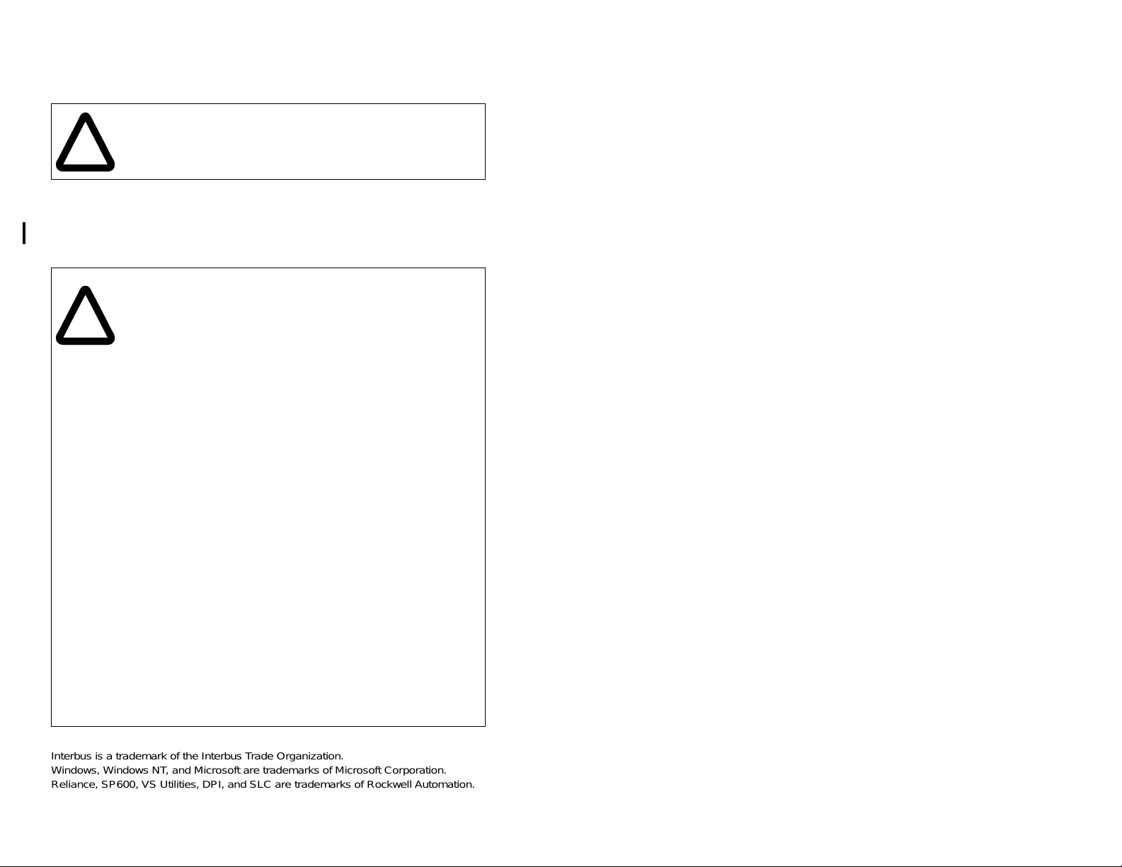
2.1 Interbus Module Components
2
Status Indicators Five LEDs that indicate the status of the
DPI Connector A 20-pin, single-row shrouded male
Bus In Interbus
Connector
Bus Out Interbus
Connector
Getting Started
connected drive, module, and network.
Refer to chapter 8, Troubleshooting the
Interbus Module and Network, for more
information.
header. An Internal Interface cable is
connected to this connector and a
connector on the dr ive.
One 6-pin plug-in connector.
One 7-pin plug-in connector.
Figure 2.1 – Components of the Interbus Module
2-1
Page 12

2.2 Required Equipment
Table 2.1 lists the equipment shipped with the Interbus module.
When you un pac k the mo dule, ve rify that t he pack age inc ludes al l of
these items.
Table 2.1 – Equipment Shipped with the Interbus Module
Item Description
One RECOMM-IBUS Interbus module
A 2.54 cm (1 in) and a 15.24 cm (6 in) Internal Interface cable
(only one cable is needed to connect the module to the drive)
LED labels
Interbus Module User Manual (D2-3480)
Table 2.2 lists user-supplied equipment also required to install and
configure the Interbus module.
Table 2.2 – Required User-Supplied Equipment
Item Description
A small flat head screwdriver
A grounding wrist strap
Interbus cable
Configuration tool, such as:
LCD OIM
•
VS Utilities (version 1.01 or later)
•
• with RECOMM-232 Serial Converter
Interbus configuration software (CMD)
2-2
Interbus Communications Module
Page 13

2.3 Installation Checklist
This section is designed to help experienced users start using the
Interbus module. If you are unsure about how to complete a step,
refer to the referenced chapter.
Step Action Refer to
U
U
U
U
U
U
U
U
1 Review the safety precautions for the
module.
2 Verify that the drive is properly installed. SP6 00 AC
3 Install the module.
Verify that the drive is not powered. Then,
connect the module to the network using a
Interbus cable and to the drive using the
Internal Interface cable. Use the captive
screws to secure and ground the module to
the drive.
4 Apply power to the module.
The module receives power from the drive.
Apply power to the drive. Refer to chapter 8,
Troubleshooting the Interb u s Modu le a nd t he
Network, if there is a problem.
5 Configure the module for your
application.
Set the parameters for the followi ng features
as required by your application:
I/O configuration.
•
Fault actions.
•
6 Apply power to the Interbus master and
other devices on the network.
Verify that the master and network are
installed and functioning in accordance with
Interbus standards, and then apply power to
them.
7 Configure the scanner to communicate
with the module.
Use a network tool for Interbus to configure
the master on the network.
8 Create a ladder logic program.
Use a programming tool to create a ladder
logic program that enables you to do the
following:
Control the module and connected drive.
•
Monitor or configure the drive using Exp licit
•
Messages.
Throughout
this manual
Drive User
Manual
Chapter 3,
Installing the
Interbus
Module
Chapter 3,
Installing the
Interbus
Module
Chapter 4,
Configuring
the Interbus
Module
Chapter 5,
Configuring
the Interbus
Scanner
Chapter 6,
Using I/O
Messaging.
Chapter 7,
Using Explicit
Messaging
(Parameter
Protocol)
Getting Started
2-3
Page 14

2-4
Interbus Communications Module
Page 15

C
HAPTER
Installing the
Interbus Module
Chapter 3 provides instructions for installing the Interbus module on
an SP600 drive.
3.1 Preparing for an Installation
Before installing the Interbus module, verify that you have all
required equipment. Refer to chapter 2, Getting Started, for a list of
equipment.
3
ATTENTION:
(Electrostatic Discharge) sensitive parts that can be
damaged if you do not follow ESD con trol procedures.
!
Static control precautions are r equired when
handling the module. Failure to observe these
precautions could result in damage to equipment.
The Interbus module contains ESD-
3.2 Connecting the Module to the
Network
ATTENTION:
that can cause injury or death. Remove all power
!
Step 1. Remove power from the drive.
Step 2. Use static control precautions.
Step 3. Route the Interbus cables through the bottom of the
Step 4. Connect the Interbus connectors to the cables. (See
from the drive, and then verify power has been
removed before installing or removing an Interbus
module. F ail ure to obse rve these pre cautions c ould
result in severe bodily injury or loss of life.
SP600 drive. (See figure 3.1.)
figure 3.1 and tables 3.1 and 3.2.)
The drive may contain high voltages
Installing the Interbus Module
3-1
Page 16

Table 3.1 – Bus In Connector (From Previous Node on the Network)
Terminal Name Description
1 /DO1 Receive
2DO1 Receive
3 /DI1 Transmit
4 DI1 Transmit
5 GND Ground Connection
6 PE Protective Earth
.
Table 3.2 – Bus Out Connector (To Next Node on the Network)
Terminal Name Description
1 /DO2 Receive
2DO2 Receive
3/DI2 Transmit
4DI2 Transmit
5
6
GND
RBST
1
1
Ground Connection
Termination
7 PE Protective Earth
1
Connect GND to RBST if the module is NOT the last module on the bus. If
the connection is not made, the module will terminate the outgoing bus.
3-2
Interbus Communications Module
Page 17

See figure 3.1 for an explanation of wiring an Interbus network.
SST SLC Scanner
DO DI COM /DO /DI
1 2 3 4 5 6 7 8 9
9-pin D-shell
jumper
Shield
Station 1
1 2 3 4 5 6
/DO1 DO1 /DI1 DI1 GND PE
Bus In
(See Table 3.1)
Step 5. Connect the Interbus connector to the module.
(See Table 3.2)
jumper
Station 2
/DO2 DO2 /DI2 DI2 GND RBST PE
1 2 3 4 5 6 7
/DO1 DO1 /DI1 DI1 GND PE
Bus Out
1 2 3 4 5 6 1 2 3 4 5 6 7
Bus In
(See Table 3.1)
Figure 3.1 – Sample Network Wiring
(See Table 3.2)(See Table 3.2)
/DO2 DO2 /DI2 DI2 GND RBST PE
Bus Out
Installing the Interbus Module
3-3
Page 18
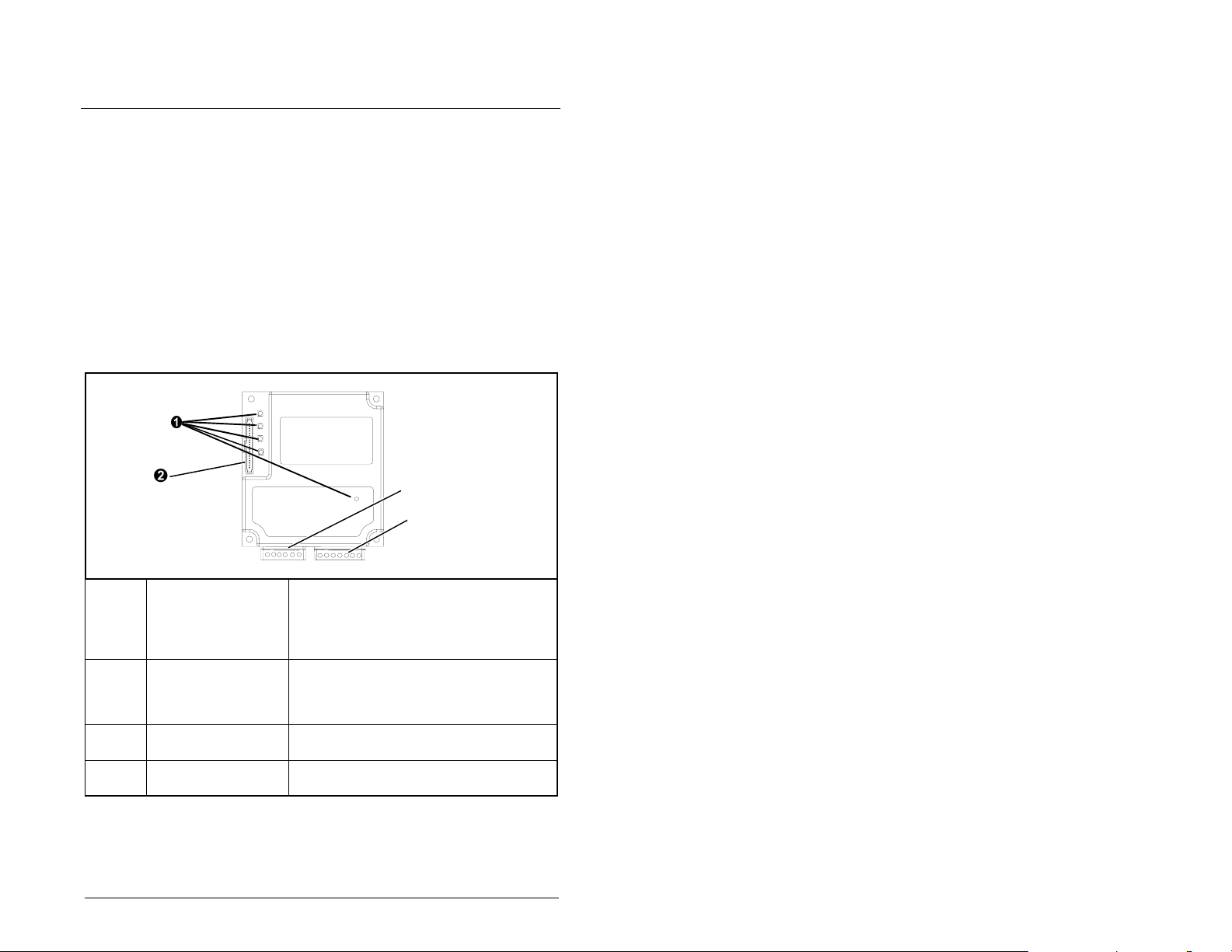
3.3 Connecting the Module to the Drive
Step 1. Remove power from the drive.
Step 2. Use static control precautions.
Step 3. Connect the Internal Interface cable to the DPI port on the
drive and then to the DPI connector on the module.
Interbus Module
# Description
15.24 cm (6 in) Internal Interface cable
DPI Connector
Interbus Connectors
2.54 cm (1 in) Internal Interface Cable
Figure 3.2 – DPI Ports and Internal Interface Cables
SP600 Drive
25-40 HP @ 460 VAC
SP600 Drive
1-20 HP @ 460 VAC
3-4
Interbus Communications Module
Page 19
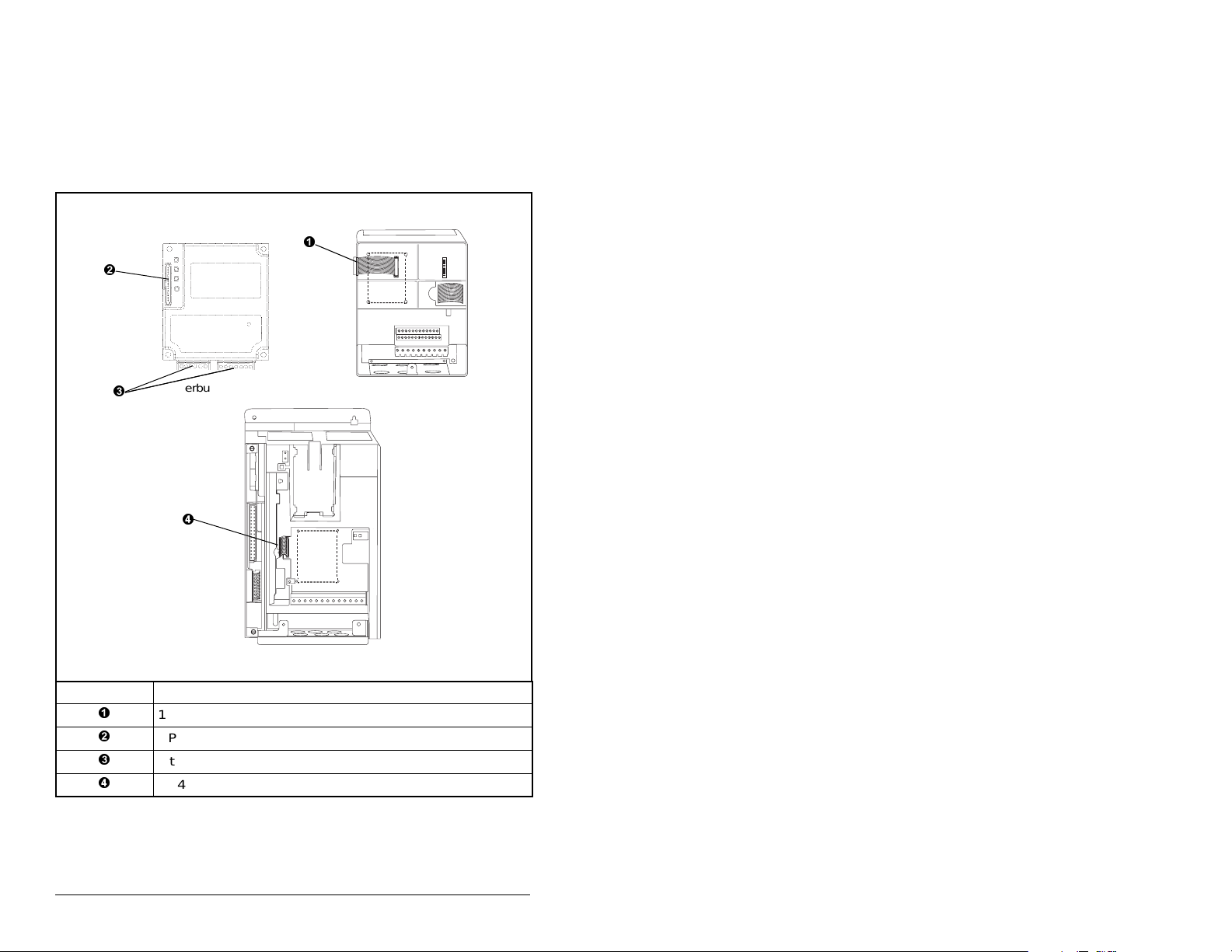
Step 4. For 1-20 HP SP600 drives: Fold the Internal Interface
Important:
cable behind the module and mount the module on the
drive using the four captive screws to secure and
ground it to the drive. See figure 3.2.
For 25-40 HP SP600 drives: Mount the module in the
drive using the four captive screws to secure and
ground it to the drive.
All screws must be tightened to ground the module.
Drive
Module
Adapter
I
nternal Interface cable
folded behind the module
and in front of the drive
SP600 Drive
Figure 3.1 – Mounting and Grounding the Interbus Module
3.4 Applying Power
ATTENTION:
if parameter settings and switch settings are not
!
Step 1. Close the doo r or reinstall the cover on th e drive. Key
Important:
Installing the Interbus Module
compatible with your application. Verify that
settings are compatible with your application
before applying power to the drive. Failure to
observe these precautions could result in severe
bodily injury or loss of life.
status indicators can be viewed on the front of the drive
after power has been applied.
Interbus compliance requires different LED
functions than what is normally displayed on the
front of the drive (DRIVE, MS, Net A, and Net B
LEDs). LED labels are provided with the module for
application to the drive cover.
Unpredictable operation may occur
3-5
Page 20

Step 2. Apply power to the SP600 drive. The module receives its
Step 3. Apply power to the master device and other devices on
power from the connected drive. When you apply power
to the product for the first time, the status indicators
should be green or off after initialization. Refer to chapter
8, Troubleshooting the Interbus Module and Network, for
more information.
the network.
3-6
Interbus Communications Module
Page 21

C
Configuring the
Interbus Module
Chapter 4 provides instructions and information for setting the
parameters in the module.
For a list of parameters, refer to Appendix B, Interbus Module
Parameters. For definitions of terms in this chapter, refer to the
Glossary.
4.1 Configuration Tools
The Interbus module stores parameters and other information in its
own non-volatile memory. Therefore, you must access the module
to view and edit its parameters. Table 4.1 lists the tools that can be
used to access the module parameters.
Table 4.1 – Configuration Tools
Tool Refer to:
VS Utilities Software (version
1.01 or later)
LCD OIM Section 4.2
HAPTER
VS Utilities online help
4
Configuring the Interbus Module
4-1
Page 22
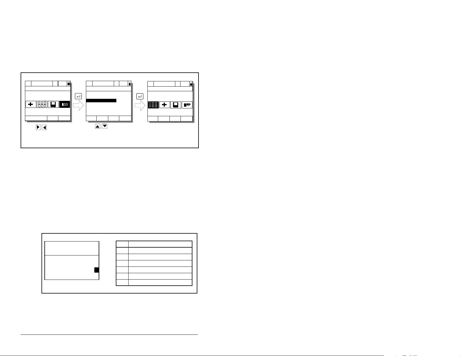
4.2 Using the LCD OIM to Configure the
pp
pp
pp
g
g
g
Module
Use the procedure in figure 4.1 to access the parameters on the
Interbus module using the LCD OIM. If you are unfamiliar with the
operation of the LCD OIM, refer to the SP600 AC Drive User Manual
(D2-3485) for more information.
>>
Sto
P0: SP600
Main Menu
Device Select
Monitor
Use to hi
Device Select icon
Auto
ed
Lan
hlight
>>
Sto
P0: SP600
Device: Port 0
SP600
RECOMM-IBUS
Use to select
RECOMM-IBUS.
Auto
ed
>>
P5: RECOMM-IBUS
Parameters
Edit the Interbus
parameters usin
same techniques as for
drive parameters.
Figure 4.1 – Accessing the Interbus Parameters using the LCD OIM
4.3 Setting the I/O Configuration
The I/O configuration determines the data that is sent to and from
the drive. This is a two part process: enabling/disabling the data
transmitted between the module and drive, and identifying the data
transmitted between the module and the scanner.
Step 1. Enable or disable the data transmitted between the
Port 5 Device
RECOMM-IBUS
Parameter #: 8
DPI I/O Config
xxxxxxxxxxx0000
Cmd/Ref b00
module and drive by setting the bits in DPI I/O Config (8).
A “1” enables the I/O. A “0” disables the I/O.
Bit Description
0 Logic Command/Reference (Default)
1 Datalink A
2 Datalink B
1
LCD OIM Screen
3 Datalink C
4 Datalink D
5 - 16 Not Used
Sto
ed
Main Menu
Auto
the
Figure 4.2 – I/O Configuration Screen on an LCD OIM
Bit 0 is the right-most bit. In figure 4.2, it is highlighted and equals
“1.”
4-2
Interbus Communications Module
Page 23

Step 2. If Logic Command/Reference is enabled, configure the
parameters in the drive to acc ept the Logic and Ref erence
from the module. For example, set Speed Ref A Sel (90)
in an SP600 drive to “Network” so that the drive uses the
Reference from the module. Also, verify that the mask
parameters (for example, Manual Mask (286)) in the drive
are configured to receive the desired logic from the
module.
Step 3. If you enabled one or more Datalinks, configure
parameters in the drive to determine the source and
destination of data in the Datalink(s). Also , ensure th at the
Interbus module is the only module using the enabl ed
Datalink(s).
Step 4. Interbus requires the network I/O mapping to be
configured first in the module . CM D softw are wi ll rea d this
configuration online when it is configuring the scanner.
Process Input Data Description (PIDD) words map input
data on the network (data seen as inputs to the scanner
and controller program). Example input data includes
Logic Status, Feedback and Datalinks (Datalink x1 Out).
Up to 9 words of input data can be mapped.
Process Output Data Description (PODD) words map
output data on the network (dat a sent as outpu ts from the
scanner and controller program). Example output data
includes Logic Command, Reference and Datalinks
(Datalink x1 In). Up to 9 words of output data can be
mapped.
Table 4.2 lists the indexes used to select the I/O data.
Input Output
Value
(Hex)
Value
(Dec) Selects
2F9A 12186 Logic Status 2F98 12184 Logic
2F9B 12187 Feedback 2F99 12185 Reference
2FA4 12196 Datalink A1 Out 2F9C 12188 Datalink A1 In
2FA5 12197 Datalink A2 Out 2F9D 12189 Datalink A2 In
2FA6 12198 Datalink B1 Out 2F9E 12190 Datalink B1 In
2FA7 12199 Datalink B2 Out 2F9F 12191 Datalink B2 In
2FA8 12200 Datalink C1 Out 2FA0 12192 Datalink C1 In
2FA9 12201 Datalink C2 Out 2FA1 12193 Datalink C2 In
2FAA 12202 Datalink D1 Out 2FA2 12194 Datalink D1 In
2FAB 12203 Datalink D2 Out 2FA3 12195 Datalink D2 In
Configuring the Interbus Module
Table 4.2 – PIDD / PODD Indexes
Value
(Hex)
Value
(Dec) Selects
Command
4-3
Page 24

To configure the module for Logic Command/Status,
Reference/Feedback and the maximum number of
Datalinks enabled in see the example in table 4.3.
Table 4.3 – Module I/O Configuration Example
Parameter # Name Value
20 PIDD W0 Cfg 2F9A 12186 Logic Status (default)
22 PIDD W1 Cfg 2F9B 12187 Feedback (default)
24 PIDD W2 Cfg 2FA4 12196 Datalink A1 Out
26 PIDD W3 Cfg 2FA5 12197 Datalink A2 Out
Input 28 PIDD W4 Cfg 2FA6 12198 Datalink B1 Out
30 PIDD W5 Cfg 2FA7 12199 Datalink B2 Out
32 PIDD W6 Cfg 2FA8 12200 Datalink C1 Out
34 PIDD W7 Cfg 2FA9 12201 Datalink C2 Out
36 PIDD W8 Cfg 2FAA 12202 Datalink D1 Out
38 PODD W0 Cfg 2F98 12184 Logic Command (default)
40 PODD W1 Cfg 2F99 12185 Reference (default)
42 PODD W2 Cfg 2F9C 12188 Datalink A1 In
44 PODD W3 Cfg 2F9D 12189 Datalink A2 In
Output 46 PODD W4 Cfg 2F9E 12190 Datalink B1 In
48 PODD W5 Cfg 2F9F 12191 Datalink B2 In
50 PODD W6 Cfg 2FA0 12192 Datalink C1 In
52 PODD W7 Cfg 2FA1 12193 Datalink C2 In
54 PODD W8 Cfg 2FA2 12194 Datalink D1 In
(Hex)
Value
(Dec)
Description
Note that Datalink D2 is no t used in this e xampl e because
maximum conf iguration has been reached. The maxim um
configura tion is shown to illustrate utilizin g all 9 words of
inputs and 9 words of outputs. Depending on your
application needs, any subset of the above example can
be implemented.
The corresponding DPI I/O Config (8) setting would be
“11111” for all of the above information to transfer
between the module and the drive.
Step 5. Reset the mod ule. Refer to the s ection 4.4.3, Resetting
the Module, in this chapter.
4-4
The module is ready to receive I/O from the master (i.e., scanner).
You must now configure the scanner to recognize and transmit I/O
to the module. Re fer to chapter 5, Configuring the Interb us Sc an ner.
Interbus Communications Module
Page 25

4.4 Settin g a Fault Action
By default, when communications are disrupted (for example, a
cable is disconnected), the drive responds by faulting if it is using
I/O from the network. You can configure a different response to
communication disruptions using Comm Flt Action (6).
ATTENTION:
the action of the module and connected SP600 drive
!
if communications are disrupted. By default, this
parameter faults the drive. You can set this
parameter so that the drive continues to run.
Precautions should be taken to ensure that the
setting of this parameter does not create a hazard
of injury or equipment damage. Failure to observe
this precaution could result in bodily injury or
damage to equipment.
Comm Flt Action (6) lets you determine
4.4.1 Changing the Fault Action
Set the value of Comm Flt Action (6) to the desired response as
shown in table 4.4. See figure 4.3 for a sample LCD OIM Fault
Action screen.
Table 4.4 – Selections for Drive Response to Communication Fault
Value Action Description
0 Fault (default) The drive is faulted and stopped.
1 Stop The drive is stopped, but not faulted.
2 Zero Data The drive is sent 0 for output data after
3 Hold Last The drive continues in its present state
4 Send Flt Cfg The drive is sent the data that you set in
(Default)
a communications disruption. This does
not command a stop.
after a commun i cations dis ru ption.
the fault configuration parameters, Flt
Cfg Logic (10) throu gh Fl t Cfg D 2 (19).
Figure 4.3 – Fault Action Screen on an LCD OIM
Changes to this parameter take effect immediately. A reset is not
required.
Configuring the Interbus Module
Port 5 Device
RECOMM-IBUS
Parameter #6:
Comm Flt Action
0
Fault
4-5
Page 26

4.4.2 Setting the Fault Configuration Parameters
If you set Comm Flt Action (6) to “Send Flt Cfg,” the values in the
following parameters are sent to the drive after a communications
fault occurs. You must set these parameters to values required by
your application.
Table 4.5 – Fault Configuration Parameters
Number Name Description
10 Flt Cfg Logic A 16-bit value sent to the drive for Logic
11 Flt Cfg Ref A 32-bit value (0 – 4294967295) sent to
12 – 19 Flt Cfg x1 In
Changes to these parame ters ta k e effect immediately . A res et is no t
required.
Command.
the drive as a Reference or Datalink.
Important:
Reference or 16-bit Datalinks, the most
significant word of the value must be set
to zero (0) or a fault will occur.
If the drive uses a 16-bit
4-6
Interbus Communications Module
Page 27

4.4.3 Resetting the Module
Changes to s witch sett ings or some mo dule par ameters re quire that
you reset the module before the new settings take effect. You can
reset the module by cycling power to the drive or by using Reset
Module (5).
ATTENTION:
I/O to the drive, the drive may fault when you reset
!
Set Reset Module (5) to Reset Module. See figure 4.4.
Port 5 Device
RECOMM-IBUS
Parameter #: 5
Reset Module
Reset Module
When you enter
reset. When you enter
module parameters to their f actory-defau lt settings. T he val ue of this
parameter will be restored to
the module. Determine how your drive will respond
before resetting a connected module. Failure to
observe this precaution could result in bodily injury
or damage to the equipment.
1
Figure 4.4 – Reset Module Screen on an LCD OIM
1 (Reset Module)
If the module is transmitting control
Value Description
0 Ready (Default)
1 Reset Module
2 Set Defaults
, the module will be immediately
2 (Set Defaults)
0 (Ready)
, the module will set all
after the module is reset.
Configuring the Interbus Module
4-7
Page 28

4.5 Viewing the Module Configuration
The parameters in table 4.6 provide information about how the
module is configured. You can view these parameters at any time.
Table 4.6 – Module Configuration Status Parameters
No. Name and Description
01
DPI Port
Port to which the module is connected. This will
usually be port 5.
03
Ref/Fdbk Size
Size of the Reference/Feedback. The drive
determines the size of the Reference/Feedback.
04
Datalink Size
Size of each Datalink word. The drive determines
the size of Datalinks.
09
DPI I/O Active
I/O that the module is actively transmitting. The
value of this parameter will usually be equal to the
value of parameter 8 - DPI I/O Config.
Bit
Default
21
PIDD W0 Actual
Actual Process Input Description for Word 0
Displays the Actual PIDD Config being transmitted
to word 0 in the Interbus Master.
23
PIDD W1 Actual
Actual Process Input Description for Word 1
Displays the Actual PIDD Config being transmitted
to word 1 in the Interbus Master.
25
PIDD W2 Actual
Actual Process Input Description for Word 2
Displays the Actual PIDD Config being transmitted
to word 2 in the Interbus Master.
27
PIDD W3 Actual
Actual Process Input Description for Word 3
Displays the Actual PIDD Config being transmitted
to word 3 in the Interbus Master.
29
PIDD W4 Actual
Actual Process Input Description for Word 4
Displays the Actual PIDD Config being transmitted
to word 4 in the Interbus Master.
31
PIDD W5 Actual
Actual Process Input Description for Word 5
Displays the Actual PIDD Config being transmitted
to word 5 in the Interbus Master.
Default: 0
Minimum: 0
Maximum: 7
Type: Read Only
Default: 0 = 16-bit
Values: 0 = 16-bit
Type: Read/Write
Default: 0 = 16-bit
Values: 0 = 16-bit
Type: Read Only
Default: xxx0 0001
Bit Values: 0 = I/O disabled
Type: Read Only
Bit Definitions
01234576
0 = Cmd/Ref
10000xxx
1 = Datalink A
2 = Datalink B
3 = Datalink C
4 = Datalink D
5 = Not Used
6 = Not Used
7 = Not Used
Value: See table 4.2
Type: Read Only
Value: See table 4.2
Type: Read Only
Value: See table 4.2
Type: Read Only
Value: See table 4.2
Type: Read Only
Value: See table 4.2
Type: Read Only
Value: See table 4.2
Type: Read Only
Details
1 = 32-bit
1 = 32-bit
1 = I/O enabled
4-8
Interbus Communications Module
Page 29

Table 4.6 – Module Configuration Status Parameters (Continued)
No. Name and Description
33 PIDD W6 Actual
Actual Process Input Description for Word 6
Displays the Actual PIDD Config being transmitted
to word 6 in the Interbus Master.
35 PIDD W7 Actual
Actual Process Input Description for Word 7
Displays the Actual PIDD Config being transmitted
to word 7 in the Interbus Master.
37 PIDD W8 Actual
Actual Process Input Description for Word 8
Displays the Actual PIDD Config being transmitted
to word 8 in the Interbus Master.
39 PODD W0 Actual
Actual Process Output Description for Word 0
Displays the actual PODD Configuration being
received from word 0 in the Interbus Master.
41 PODD W1 Actual
Actual Process Output Description for Word 1
Displays the actual PODD Configuration being
received from word 1 in the Interbus Master.
43 PODD W2 Actual
Actual Process Output Description for Word 2
Displays the actual PODD Configuration being
received from word 2 in the Interbus Master.
45 PODD W3 Actual
Actual Process Output Description for Word 3
Displays the actual PODD Configuration being
received from word 3 in the Interbus Master.
47 PODD W4 Actual
Actual Process Output Description for Word 4
Displays the actual PODD Configuration being
received from word 4 in the Interbus Master.
49 PODD W5 Actual
Actual Process Output Description for Word 5
Displays the actual PODD Configuration being
received from word 5 in the Interbus Master.
51 PODD W6 Actual
Actual Process Output Description for Word 6
Displays the actual PODD Configuration being
received from word 6 in the Interbus Master.
53 PODD W7 Actual
Actual Process Output Description for Word 7
Displays the actual PODD Configuration being
received from word 7 in the Interbus Master.
55 PODD W8 Actual
Actual Process Output Description for Word 8
Displays the actual PODD Configuration being
received from word 8 in the Interbus Master.
57 PCP Comm Act
Actual PCP configuration
Details
Value: See table 4.2
Type: Read Only
Value: See table 4.2
Type: Read Only
Value: See table 4.2
Type: Read Only
Value: See table 4.2
Type: Read Only
Value: See table 4.2
Type: Read Only
Value: See table 4.2
Type: Read Only
Value: See table 4.2
Type: Read Only
Value: See table 4.2
Type: Read Only
Value: See table 4.2
Type: Read Only
Value: See table 4.2
Type: Read Only
Value: See table 4.2
Type: Read Only
Value: See table 4.2
Type: Read Only
Value: Enabled, Disabled
Configuring the Interbus Module
4-9
Page 30

4-10
Interbus Communications Module
Page 31

C
HAPTER
Configuring the
Interbus Scanner
A scanner is a separate module of a multi-module controller or a
built-in component of a single-module controller that provides
communication with a module connected to a network.
Interbus scanners are available from several manufacturers,
including SST. Chapter 5 provides instructions on how to use
Phoenix Contact CM D softw are to confi gure th e netw ork on an SST
scanner .
5.1 Configuring a Simple Network:
An Example
All examples in this manual are based on the following:
SLC controller with an SST Interbus scanner (SST-IBS-SLC)
•
in slot 1.
SP600 drive at Device 1.0 / CR 2 (CR# is needed for PCP
•
commands).
SP600 drive at Device 2.0 / CR 3 (CR# is needed for PCP
•
commands).
Logic Command/Status, Reference/Feedback and Datalinks A-D
•
are enabled in the RECOMM-IBUS and mapped to network
I/O.
Phoenix Contact CMD software is used to configure the network.
•
5
This chapter describes the steps to configure a simple network like
the one featured in figure 5.1.
Configuring the Interbus Scanner
5-1
Page 32

Interbus Scanner in
Multi-Module Controller
Interbus
REMOTE OUT
Config
RS232 Port
Fault LED
COMM LED
SP600 Drive
Station 1.0
(CR=2)
Figure 5.1 – Sample Interbus Network
SP600 Drive
Station 2.0
(CR=3)
5.2 Configuring the Module for use with
the Ladder Examples
Prior to setting up the SST Inte rbus sc anner with C MD softw are, the
parameters listed in table 5.1 need to be configured to use the
sample ladder logic program.
Table 5.1 – Module Parameter Settings for Ladder Example
Value
Binary/
Parameter Name
Decimal Hexadecimal
8 DPI I/O Config xxx1 1111 001F Enable Cmd/Ref,
20 PIDD W0 Cfg 12186 2F9A Logic Status
22 PIDD W1 Cfg 12187 2F9B Feedback
24 PIDD W2 Cfg 12196 2FA4 Datalink A1 Out
26 PIDD W3 Cfg 12197 2FA5 Datalink A2 Out
Description
Datalinks A-D
5-2
Interbus Communications Module
Page 33

Table 5.1 – Module Parameter Settings for Ladder Example (Continued)
Value
Binary/
Parameter Name
28 PIDD W4 Cfg 12198 2FA6 Datalink B1 Out
30 PIDD W5 Cfg 12199 2FA7 Datalink B2 Out
32 PIDD W6 Cfg 12200 2FA8 Datalink C1 Out
34 PIDD W7 Cfg 12201 2FA9 Datalink C2 Out
36 PIDD W8 Cfg 12202 2FAA Datalink D1 Out
38 PODD W0 Cfg 12184 2F98 Logic Command
40 PODD W1 Cfg 12185 2F99 Reference
42 PODD W2 Cfg 12188 2F9C Datalink A1 In
44 PODD W3 Cfg 12189 2F9D Datalink A2 In
46 PODD W4 Cfg 12190 2F9E Datalink B1 In
48 PODD W5 Cfg 12191 2F9F Datalink B2 In
50 PODD W6 Cfg 12192 2FA0 Datalink C1 In
52 PODD W7 Cfg 12193 2FA1 Datalink C2 In
54 PODD W8 Cfg 12194 2FA2 Datalink D1 In
PIDD and PODD parameters are used to identify what will be
transmitted on t he n etwork and the amount of ne twork I/O the CMD
software will allocate on the scanner.
Decimal Hexadecimal
Description
5.3 Configuring the Network Using CMD
Software
Before starting the network configuration process, make sure the
PC running CMD software is connected to the SST scanner (a null
modem cable is supplied with t he scanner). The SLC and drives
need to be conne cted to the Interbus network and powered in order
for CMD software to configure the network. The CMD software tool
automatically creates a Reliance Electric sub-folder (in the Slaves
folder), if it does not already exist.
CMD needs to be in Extended Mode to configure the network. A
password (supplied by Phoenix Contact along with the CMD
software), is requested for this functionality each time CMD is
started. After CMD has started, you can also click O
xtended (Function Scope) to enter the password.
E
Step 1. Select F
new project. (See figure 5.2.)
Configuring the Interbus Scanner
ile / New from the pull-down menu to create a
ptions/
5-3
Page 34

Figure 5.2 – Creating a New Interbus Project using CMD
Step 2. Right-click on the Project icon and select
Description. Enter a name for the project and any
additional information desired, as shown in figure 5.3.
Click OK when comp lete.
SP600 Interbus Demo
An SP600 Interbus demonstration
program using an SLC-5/05
system with an SST-IBS-SLC
Interbus scanner.
Figure 5.3 – Entering a Name for the New Interbus Project
Step 3. Right-click on the PLC/PC icon and select
Description. Enter a name for the controller and any
additional information desired, as shown in figure 5.4.
Click OK when comp lete.
5-4
Interbus Communications Module
Page 35

Figure 5.4 – Entering a Name for the Interbus Controller
Step 4. Right-click on the Program icon and select
Description. Enter a name for the program (the actual
RSLogix500 file name is recommended), and any
additional information desired, as shown in figure 5.5.
Click OK when comp lete.
Using SP600 w/RECOMM-IBUS
Figure 5.5 – Entering a Name for the Interbus Program
Step 5. When complete, the representation area will look as
shown in figure 5.6.
SP600 Interbus Demo
Figure 5.6 – Sample Interbus CMD Project
Configuring the Interbus Scanner
5-5
Page 36

This provides useful information regarding the CMD project
being created:
• “SP600 Interbus Demo” indicates what this project is
for.
• “SLC 5/05” indicates the contro ller used.
• “Interbus_SLC_Demo” indicates that
Interbus_SLC_Demo.RSS is the associated
RSLogix500 program used with this system.
Step 6. To configure the PC Com Port that CMD will use to
communicate with the SST scanner, click on Options/
Settings and then the Driver tab.
Step 7. Click on the Communication Path icon and then the
Standard tab.
Step 8. Select the port communication path. Typically, this is
“Serial Port” and “Com1” respectively, as shown in figure
5.7. Click OK until you return to the main screen.
5-6
Figure 5.7 – Selecting the Port Communication Path
Step 9. Right-click on the Controller Board icon and select
Type. Set the type to “IBS USC/4(4K)” and click OK. This
identifies the type of Interbus controller used on the SST
scanner. (See figure 5.8.)
Interbus Communications Module
Page 37

Figure 5.8 – Selecting the Interbus Controller Type
Step 10. Right-click on the Controller Board icon and select
Description. Enter “SST-IBS-SLC” in the name field, as
shown in figure 5.9.
Figure 5.9 – Entering a Description for the Controller Board
Step 11. When complete, the representation area will look as
shown in figure 5.10.
Configuring the Interbus Scanner
5-7
Page 38

.
SP600 Interbus Demo
Figure 5.10 – Sample Interbus CMD Project
Step 12. From the pull-down menu select Configuration/
Configuration Fr ame/Read In and answ er Yes to changing
the operating state to Configuration Online. If there are
additional prompts , answer OK or Yes to perform the read
anyway. CMD will then read the bus configuration. (See
figure 5.11.)
SP600 Interbus Demo
5-8
Figure 5.11 – CMD Bus Configuration
The gray PCP icons represent each SP600 drive. The first SP600
drive has a Device Number of 1.0 and the second has a Device
Number of 2.0.
Interbus Communications Module
Page 39

Step 13. Right-click on the SST-IBS-SLC scanner and select
Process Data. This shows the Interbus I/O mapping for
each device on the network, as shown in figure 5.12.
Figure 5.12 – Sample Interbus I/O Mapping
In the example, the length is 144 bits (9 words) because the
RECOMM-IBUS was previously configured for the maximum I/O
configuration. (See section 4.3, Setting the I/O Configuration.
Depending on your application needs, this length may be less.)
The scanner mapping correlates to SLC addressing as shown in
figure 5.13.
Scanner Scanner
(USC/4) Output SLC (USC/4) Input SLC
0
1
63
64
65
511
Figure 5.13 – Scanner Mapping / SLC Addressing
Configuring the Interbus Scanner
O:x.0(high)
O:x.0(low)
O:x.31(low)
M0:x.0(high)
M0:x.0(low)
M0:x.223(low)
512
513
575
576
1023
I:x.0(high)
I:x.0(low)
I:x.31(low)
M1:x.0(high)
M1:x.0(low)
M1:x.223(low)
5-9
Page 40

The mapping in the scann er is se t up in b ytes . In puts t o the s cann er
start at byte #512 and outputs start at byte #0.
PIDD/PODD parameter setting s in the m odule d etermine the l ength
of I/O data mapped. In the example, each device is configured for 9
words (144 bits) of inputs and 9 words (144 bits) of outputs, the
maximum allowed for each device.
Using the PIDD/PODD values previously set in the RECOMM-IBUS
module, the I/O layout in the scanner is as shown in table 5.2.
Table 5.2 – Scanner I/O Layout
Word
Inputs
(Data to Master)
Station Outputs
(Data from
1.0 2.0 1.0 2.0
Master)
Station
0 Logic Status 512 530 Logic Command 0 18
1 Feedback 514 532 Reference 2 20
2 Datalink A1 Out 516 534 Datalink A1 In 4 22
3 Datalink A2 Out 518 536 Datalink A2 In 6 24
4 Datalink B1 Out 520 538 Datalink B1 In 8 26
5 Datalink B2 Out 522 540 Datalink B2 In 10 28
6 Datalink C1 Out 524 542 Datalink C1 In 12 30
7 Datalink C2 Out 526 544 Datalink C2 In 14 32
8 Datalink D1 Out 528 546 Datalink D1 In 16 34
Device 1.0’s SLC addressing is as follows:
Table 5.3 – SLC Addressing for Device 1.0
Inputs
(Data to
Word
Master)
0 Logic Status 512 I:1.0 Logic
Assignment Outputs
Assignment
(Data from
Scanner SLC Scanner SLC
Master)
0 O:1.0
Command
1 Feedback 514 I:1.1 Reference 2 O:1.1
2 Datalink A1 Out 516 I:1.2 Datalink A1 In 4 O:1.2
3 Datalink A2 Out 518 I:1.3 Datalink A2 In 6 O:1.3
4 Datalink B1 Out 520 I:1.4 Datalink B1 In 8 O:1.4
5 Datalink B2 Out 522 I:1.5 Datalink B2 In 10 O:1.5
6 Datalink C1 Out 524 I:1.6 Datalink C1 In 12 O:1.6
7 Datalink C2 Out 526 I:1.7 Datalink C2 In 14 O:1.7
8 Datalink D1 Out 528 I:1.8 Datalink D1 In 16 O:1.8
Device 2.0’s SLC addressing starts immediately after 1.0
addressing (I:1.9 and O:1.9).
5-10
Interbus Communications Module
Page 41

Step 14. Right-click on the 1.0 PCP icon and select
D
escription. Enter a Station N ame such as “SP600 Demo
#1”. Note the Communication Reference (CR) is 2. The
CR needs to be known when using PCP communication
services (explicit messaging). (See figure 5.14.)
SP600 Demo #1
Figure 5.14 – Entering a Station Name
Step 15. Click on the Parameter Channel button. Set Transmit and
Receive to 128 bytes and enable Read, Write, and
Get-0D (long format) services, as shown in figure 5.15.
Click OK when comp lete.
Configuring the Interbus Scanner
5-11
Page 42

Figure 5.15 – Selecting Data for the Parameter Channel Screen
Step 16. Repeat steps #14 and #15 using the 2.0 PCP icon .
Enter a Station name such as “SP600 Demo #2 ”. Note the
Communication Ref erence (CR) is 3. The CR ne eds to be
known when using PCP communication services (explicit
messaging). Cli ck OK wh en complete.
Step 17. When complete, the representation area will look as
shown in figure 5.16.
5-12
Interbus Communications Module
Page 43

SP600 Demo #1
SP600 Demo #2
Figure 5.16 – Sample SP600 Demo #2
Step 18. Right-click on the SST-IBS-SLC icon and select
arameterization/Execute. Select “Startup without PDP”
P
as shown in figure 5.17, and click OK. This uses the
mapping already se t up in the scanne r and does not al low
re-mapping by the software tool.
Configuring the Interbus Scanner
5-13
Page 44

.
Figure 5.17 – Selecting Data for Parameterization/Execute Screen
If parameterization execution is successful, there will be a prompt to
click OK. Click OK.
Step 19. When complete, the representation area will look as
shown in figure 5.18.
5-14
SP600 Demo #1
SP600 Demo #2
Figure 5.18 – Sample Parameterization Execution
Step 20. Click F
project.
ile/Save from the pull-down menu and save the
Interbus Communications Module
Page 45

5.4 Configuring the SP600 Drive for use
with the Ladder Examples
Configure the parameters as shown in table 5.4 to use the sample
ladder logic program.
Table 5.4 – SP600 Parameter Settings for Ladder Examples
Parameter Name Value Description
90 Speed Ref A Sel 22 Network (RECOMM-IBUS)
300 Data In A1 140 Accel Time 1 (140)
301 Data In A2 142 Decel Time 1 (142
302 Data In B1 100 Jog Speed (100)
303 Data In B2 155 Stop Mode A (155)
304 Data In C1 101 Preset Speed 1 (101)
305 Data In C2 102 Preset Speed 2 (102)
306 Data In D1 103 Preset Speed 3 (103)
310 Data Out A1 140 Accel Time 1 (140)
311 Data Out A2 142 Decel Time (142)
312 Data Out B1 100 Jog Speed (100)
313 Data Out B2 155 Stop Mode A (155)
314 Data Out C1 101 Preset Speed 1 (101)
315 Data Out C2 102 Preset Speed 2 (102)
316 Data Out D1 103 Preset Speed 3 (103)
provides the Reference
Configuring the Interbus Scanner
5-15
Page 46

5.5 Configuring the RSLogix 500 SST
Interbus Scanner
The SST Interbus scanner is configured by clicking on the I/O
Configuration in RSLogi x5 00. The SST-IBS-SLC scanne r ha s an ID
Code of 13635. The settings in figures 5.19 and 5.20 are used by
the sample ladder logic program.
Figure 5.19 – Scanner I/O Configuration
5-16
Figure 5.20 – Scanner_G_Files
Interbus Communications Module
Page 47

Table 5.5 – G File Data Information
Word
Value
(Decimal)
Value
(Hexadecimal) Description
0 8224 2020 Fixed to 2020h by the SLC
1 4096 1000 Enables the command in terface
between the SLC and the USC/4
2 0 0 Use the CMD specified Bus Update
Time
3 0 0 Use the CMD specified Bus Warning
Time
4 0 0 Use the CMD specified Bus Timeout
5 0 0 The number of words used at the
beginning of the M files for In puts
and Outputs
6 128 80 Maximum data size for commands
and replies sent between the SLC
and the scanner
Refer to the SST_IBS_SLC User’s Guide for more information.
Configuring the Interbus Scanner
5-17
Page 48

5-18
Interbus Communications Module
Page 49

C
HAPTER
6
Using I/O Messaging
Chapter 6 provides information and examples that explain how to
use I/O Messaging to control an SP600 drive.
ATTENTION:
intended so lely for purposes of example. There are
!
many variables and requirements with any
application. Rockwell Au t om atio n doe s not as su me
responsibility or liability (to include intellectual
property liability) for actual use of the examples
shown in this publication. Failure to observe this
precaution coul d result i n bodily injury or dam age to
equipment.
The examples in this publication are
6.1 About I/O Messaging
I/O messaging is used to tr ansfe r the data which controls the SP600
drive and sets its Ref erence . I/ O can al so be use d to tran sf er data to
and from Datalinks in SP600 drives.
The Interbus m odu le provides opti ons for configuring and using I/O,
including the following:
The size of I/O can be configured by enabling or disabling the
•
Logic Command/Reference and Datalinks.
Chapter 4, Configuring the Interbus Module, and chapter 5,
Configuring the Interbus Scanner, discuss how to configure the
module and scann er on the netwo rk for these op tions . The Gl ossary
defines the different options. This chapter discusses how to use I/O
after you have configured the module and scanner.
6.2 Understanding the I/O Image
The terms
view. Therefore, Output I/O is data that is output fr om the scanner
and consumed by the Interbus module. Input I/O is status data that
is produced by the module and consumed as input by the scanner.
Using I/O Messaging
input
and
are defined from scanner’s point of
output
6-1
Page 50

The I/O image table will vary based on the following:
Size (either 16-bi t or 32-bit) of the Reference/Feedback word an d
•
Datalink words used by the drive.
Configuration of DPI I/O Config (8) in the module. If all I/O is not
•
enabled, the image table is truncated. The image table always
uses consecutive words starting at word 0.
Figure 6.1 illustrates an example of an I/O image with 16-bit words.
Controller
Scanner
Output
Image
(Write)
M0/M1
Files
Input
Image
(Read)
M0/M1
Files
Interbus
Module SP600 Drive
DPI
Word and I/O
0 Logic Command
1 Reference
2 Datalink In A1
3 Datalink In A2
4 Datalink In B1
5 Datalink In B2
6 Datalink In C1
7 Datalink In C2
8 Datalink In D1
PCP Communications
0 Logic Status
1 Feedback
2 Datalink Out A1
3 Datalink Out A2
4 Datalink Out B1
5 Datalink Out B2
6 Datalink Out C1
7 Datalink Out C2
8 Datalink Out D1
PCP
Communications
Logic Command
Reference
Data In A1
Data In A2
Data In B1
Data In B2
Data In C1
Data In C2
Data In D1
Message
Handler
Logic Status
Feedback
Data Out A1
Data Out A2
Data Out B1
Data Out B2
Data Out C1
Data Out C2
Data Out D1
Message
Handler
6-2
Figure 6.1 – Sample I/O Image with All I/O Enabled
Interbus Communications Module
Page 51

An image that us es 32 -bi t words for R eference and Datalinks would
change the I/O image as follows:
Word I/O
0 Logic Command/Status
1 - 2 Reference/Feedback
3 - 6 Datalink A1/A2
7 - 10 Datalink B1/B2
Figure 6.2 illustrates an example of an I/O image that does not use
all of the I/O data. Only the Logic Command/Reference and
Datalink B are enabled. In this example, the Reference is a 32-bit
word, and Datalinks are 16-bit words.
Interbus
Controller Scanner Module SP600 Drive
Word and I/O
Output
Image
(Write)
Input
Image
(Read)
LSW = Least Significant Word (Bits 15 - 0)
MSW = Most Significant Word (Bits 31 - 16)
0 Logic Command
1 Reference (LSW)
2 Reference (MSW)
3 Datalink In B1
4 Datalink In B2
0 Logic Status
1 Feedba ck (LSW)
2 Feedba ck (MSW)
3 Datalink Out B1
4 Datalink Out B2
DPI
Logic Command
Reference
Data In A1
Data In A2
Data In B1
Data In B2
Data In C1
Data In C2
Data In D1
Logic Status
Feedback
Data Out A1
Data Out A2
Data Out B1
Data Out B2
Data Out C1
Data Out C2
Data Out D1
Figure 6.2 – Sample I/O Image with Only Logic/Reference and Datalink B
Using I/O Messaging
Enabled
6-3
Page 52

6.3 Using Logic Command/Status
When enabled, th e Logic Command/Stat us word is alw ays w ord 0 in
the I/O image. The
produced by the scanner and consumed by the module. The
is a 16-bit word of status produced by the module and
Status
consumed by the scanner.
This manual contains the bit definitions for compatible products
available at the time of publication in Appendix C, Logic Command/
Status Words. For other products, refer to their documentation.
Logic Command
is a 16-bit word of control
6.4 Using Reference/Feedback
When enabled, Ref ere nce/Feedback always begi ns at wo rd 1 in the
I/O image. The
controller and consumed by the module. The
32 bits) is produced by the module and consumed by the con trol ler.
The size of the Reference/Feedback is determined by the product
and displayed in Re f/Fdbk Size (3) in the module.
Size Valid Values In I/O Image Example
16-bit -32768 to 32767 Word 1 Figure 6.1
32-bit -2147483648 to
Reference
2147483647
(16 bits or 32 bits) is produced by the
Feedback
Word 1 and
Word 2
Logic
(16 bits or
Figure 6.2
6.5 Using Datalinks
A Datalink is a mechanism used by SP600 driv es to tr ansf e r data to
and from the controller. Datalinks allow a parameter value to be
changed without using an Explicit Message.
When enabled, each Datalink consumes either two 16-bit or 32-bit
words in both the input an d output image depen ding on its siz e. Th e
size of Datalinks (16-b it words or 32-bit wo rds) is det ermined b y the
drive and displayed in Datalink Size (4) in the module.
6.5.1 Rules for Using Datalinks
Each set of Datalink parameters in an SP600 drive can be used
•
by only one module. If more than one module is connected to a
single drive, multiple modules must not try to use the same
Datalink.
Parame ter settings in the drive determine the data pass ed
•
through the Datalink mechanism. Refer to the documentation for
your product.
6-4
Interbus Communications Module
Page 53

When you use a Datalink to change a value, the value is not
•
written to the Non-Volatile Storage (NVS). The value is stored in
volatile memory and lost when the drive loses power.
6.5.2 32-Bit Parameters using 16-Bit Datalinks
To read (and/or write) a 32-bit parameter using 16-bit Datalinks,
typically both Datalinks (x1 and x2) are set to the 32-bit parameter.
For example, to read Elapsed MWh (9) in an SP600 drive, both
Datalink A1 and A2 are set to “9.” Datalink A1 will contain the least
significant word (LSW) and Datalink A2 the most significant word
(MSW). In this example, the parameter 9 value of 5.8 MWh is read
as a “58” in Datalink A1.
Datalink
Most/Least
Significant Word Paramete r
Data
(decimal)
A1 LSW 9 58
A2 MSW 9 0
Regardless of the Datalink combination, x1 will always contain the
LSW and x2 will always contain the MSW. In the following
examples, Power Up Marker (242) contains a value of 88.4541
hours.
Datalink
Most/Least
Significant Word Parameter
Data
(decimal)
A1 LSW 242 32573
A2 - Not Used - 0 0
Datalink
Most/Least
Significant Word Parameter
Data
(decimal)
A1 - Not Used - 0 0
A2 MSW 242 13
Datalink
Most/Least
Significant Word Parameter
Data
(decimal)
A2 MSW 242 13
B1 LSW 242 32573
32-bit data is stored in binary as follows:
MSW
LSW
Using I/O Messaging
31
through 2
2
15
through 2
2
16
0
6-5
Page 54

Example:
Power Up Marker (242) = 88.4541 hours
MSW = 13
LSW = 32573
851968 + 32573 = 884541
decimal
= 1101
= 219 + 218 + 216 = 851968
binary
6.6 Sample SLC Ladder Logic Program
The sample Interbus program uses an SLC processor with an SST
Interbus scanner (SST-IBS-SLC) in the first slot of the rack and
works with SP600 drives.
Function of the Sample Program
The program is written for (2) drives on the network and
demonstrates using:
Logic Command / Reference
•
Logic Status / Feedback
•
Datalinks
•
PCP Read / Write (See chapter 5.)
•
Module Settings
The RECOMM-IBUS node addresses are set via CMD software to:
“1.0” (CR=2) for Station 1
•
“2.0” (CR=3) for Station 2
•
6-6
See section 5.2, Configuring the Module for use with the Ladder
Examples.
SP600 Settings
See section 5.4, Configuring the SP600 Drive for use with the
Ladder Examples.
SST Scanner Settings
See section 5.5, Configuring the RSLogix 500 SST Interbus
Scanner.
Interbus Communications Module
Page 55

SLC Data T ab le
Read Data
The scanner is configured for 18 bytes (9 words) of inputs for each
drive, the maximum amount allowed. Two drives require 36 bytes
(18 words) maximum.
Station 1
Address
I:1.0 I:1.9 Logic Status
I:1.1 I:1.10 Feedback
I:1.2 I:1.11 Datalink A1
I:1.3 I:1.12 Datalink A2
I:1.4 I:1.13 Datalink B1
I:1.5 I:1.14 Datalink B2
I:1.6 I:1.15 Datalink C1
I:1.7 I:1.16 Datalink C2
I:1.8 I:1.17 Datalink D1
Station 2
Address Function
Write Data
The scanner is configu red for 18 bytes (9 words) of outputs for each
drive, the maximum amount allowed. Two drives require 36 bytes
(18 words).
Station 1
Address
O:1.0 O:1.9 Logic Command
O:1.1 O:1.10 Reference
O:1.2 O:1.11 Datalink A1
O:1.3 O:1.12 Datalink A2
O:1.4 O:1.13 Datalink B1
O:1.5 O:1.14 Datalink B2
O:1.6 O:1.15 Datalink C1
O:1.7 O:1.16 Datalink C2
O:1.8 O:1.17 Datalink D1
Station 2
Address Function
Logic Command/Status Words
These examples use the Logic Command word and Logic Status
word for SP600 drives. Refer to Appendix C, Logic Command/
Status Words to vie w these . The d efiniti on of t he bits in th ese w ords
may vary if you are using a different DPI product. Refer to the
documentation for your product.
Using I/O Messaging
6-7
Page 56

6.6.1 Sample SLC Ladder Logic - Main Program
The following rung performs power-up initialization of the PCP Read and PCP Write routines.
First Pass
0000
0001
0002
0003
0004
0005
S:1
15
Execute LAD 3 - Station 1.0 Drive Logic (Logic Command / Status, Reference / Feedback and Datalinks).
Execute LAD 4 - Station 2.0 Drive Logic (Logic Command / Status, Reference / Feedback and Datalinks).
Execute LAD 5 - PCP Read Subroutine (Explicit Messaging)
Can Read OR Write at any one time. B3:47/0 will be turned off by the subroutine when the reading is complete and signals that
another read (or write) cycle can take place.
Execute
PCP Read
Subroutine
Execute LAD 6 - PCP Write Subroutine (Explicit Messaging)
Can only Write OR Read at any one time. B3:47/10 will be turned off by the subroutine when the writing is complete and
signals that another write (or read) cycle can take place.
Execute
PCP Read
Subroutine
B3:47
B3:47
Execute
PCP Write
Subroutine
B3:47
0
10
Execute
PCP Write
Subroutine
B3:47
10
0
JSR
JSR
Jump To Subroutine
SBR File Number U:3
JSR
JSR
Jump To Subroutine
SBR File Number U:4
JSR
JSR
Jump To Subroutine
SBR File Number U:5
JSR
JSR
Jump To Subroutine
SBR File Number U:6
Execute
PCP Read
Subroutine
B3:47
U
0
PCP Read
Routine
1-shot
B3:47
U
1
PCP Read
Reply Msg
1-Shot
B3:47
U
2
Execute
PCP Write
Subroutine
B3:47
U
10
PCP Write
Routine
1-shot
B3:47
U
11
PCP Write
Reply Msg
1-Shot
B3:47
U
12
END
6-8
Figure 6.3 – Sample SLC Ladder Logic - Main Program
Interbus Communications Module
Page 57

Controlling the Logic Command to the drive at Station 1.0.
Station 1.0
Start
Command
0000
0001
0002
0003
0004
0005
0006
B3:20
1
Station 1.0
Stop
Command
B3:20
0
Station 1.0
Jog
Command
B3:20
2
Station 1.0
Clear Faults
Command
B3:20
3
Station 1.0
Reverse
Command
B3:20
4
Station 1.0
Reverse
Command
B3:20
4
Station 1.0 Speed Reference
SP600 Speed Ref A Sel (90) needs to be set to “Network”
PowerFlex 70 Speed Ref A Sel (Pr.90) needs to be set to 'DPI Port 5'
Station 1.0
Logic Command
START
Station 1.0
Logic Command
STOP
Station 1.0
Logic Command
JOG
Station 1.0
Logic Command
CLEAR FAULTS
Station 1.0
Logic Command
FORWARD
Station 1.0
Logic Command
REVERSE
Station 1.0
Speed Reference
MOV
MOV
Move
Source N19:1
8192<
Dest O:1.1
8192<
O:1.0
OTHER
O:1.0
OTHER
O:1.0
OTHER
O:1.0
OTHER
O:1.0
OTHER
O:1.0
OTHER
1
0
2
3
4
5
Station 1.0 Datalink A1
Datalink A1 (Pr. 300) set to Acceleration Time 1 (Pr. 140)
0007
Figure 6.4 – Sample SLC Ladder Logic - Station 1 Program
Using I/O Messaging
Station 1.0
Datalink A1
MOV
MOV
Move
Source N19:2
50<
Dest O:1.2
50<
6-9
Page 58

Station 1.0 Datalink A2
Datalink A2 (Pr. 301) set to Deceleration Time 1 (Pr. 142)
0008
Station 1.0 Datalink B1
Datalink B1 (Pr. 302) set to Jog Speed (Pr. 100)
0009
Station 1.0 Datalink B2
Datalink B2 (Pr. 303) set to Stop Mode A (Pr. 155)
0010
Station 1.0 Datalink C1
Datalink C1 (Pr. 304) set to Preset Speed 1 (Pr. 101)
0011
Station 1.0 Datalink C2
Datalink C2 (Pr. 305) set to Preset Speed 2 (Pr. 102)
0012
Station 1.0
Datalink A2
MOV
MOV
Move
Source N19:3
50<
Dest O:1.3
50<
Station 1.0
Datalink B1
MOV
MOV
Move
Source N19:4
100<
Dest O:1.4
100<
Station 1.0
Datalink B2
MOV
MOV
Move
Source N19:5
1<
Dest O:1.5
1<
Station 1.0
Datalink C1
MOV
MOV
Move
Source N19:6
100<
Dest O:1.6
100<
Station 1.0
Datalink C2
MOV
MOV
Move
Source N19:7
200<
Dest O:1.7
200<
Station 1.0 Datalink D1
Datalink D1 (Pr. 306) set to Preset Speed 3 (Pr. 103)
0013
0014
Station 1.0
Datalink D1
Figure 6.5 – Sample SLC Ladder Logic - Station 1 Program (Continued)
6-10
Interbus Communications Module
MOV
MOV
Move
Source N19:8
300<
Dest O:1.8
300<
END
Page 59

6.6.2 Sample SLC Ladder Logic - Station 2 Program
Controlling the Logic Command to the drive at Station 2.0.
Station 2.0
Start
Command
0000
0001
0002
0003
0004
0005
0006
B3:21
1
Station 2.0
Stop
Command
B3:21
0
Station 2.0
Jog
Command
B3:21
2
Station 2.0
Clear Faults
Command
B3:21
3
Station 2.0
Reverse
Command
B3:21
4
Station 2.0
Reverse
Command
B3:21
4
Station 2.0 Speed Reference
SP600 Speed Ref A Sel (90) needs to be set to “Network”
PowerFlex 70 Speed Ref A Sel (Pr.90) needs to be set to 'DPI Port 5'
Station 2.0
Logic Command
START
Station 2.0
Logic Command
STOP
Station 2.0
Logic Command
JOG
Station 2.0
Logic Command
CLEAR FAULTS
Station 2.0
Logic Command
FORWARD
Station 2.0
Logic Command
REVERSE
Station 2.0
Speed Reference
MOV
MOV
Move
Source N19:15
8192<
Dest O:1.10
8192<
O:1.9
1
OTHER
O:1.9
0
OTHER
O:1.9
2
OTHER
O:1.9
3
OTHER
O:1.9
4
OTHER
O:1.9
5
OTHER
Station 2.0 Datalink A1
Datalink A1 (Pr. 300) set to Acceleration Time 1 (Pr. 140)
0007
Figure 6.6 – Sample SLC Ladder Logic - Station 2 Program
Using I/O Messaging
Station 2.0
Datalink A1
MOV
MOV
Move
Source N19:16
50<
Dest O:1.11
50<
6-11
Page 60

Station 2.0 Datalink A2
Datalink A2 (Pr. 301) set to Deceleration Time 1 (Pr. 142)
0008
Station 2.0 Datalink B1
Datalink B1 (Pr. 302) set to Jog Speed (Pr. 100)
0009
Station 2.0 Datalink B2
Datalink B2 (Pr. 303) set to Stop Mode A (Pr. 155)
0010
Station 2.0 Datalink C1
Datalink C1 (Pr. 304) set to Preset Speed 1 (Pr. 101)
0011
Station 2.0 Datalink C2
Datalink C2 (Pr. 305) set to Preset Speed 2 (Pr. 102)
0012
Station 2.0
Datalink A2
MOV
MOV
Move
Source N19:17
50<
Dest O:1.12
50<
Station 2.0
Datalink B1
MOV
MOV
Move
Source N19:18
100<
Dest O:1.13
100<
Station 2.0
Datalink B2
MOV
MOV
Move
Source N19:19
1<
Dest O:1.14
1<
Station 2.0
Datalink C1
MOV
MOV
Move
Source N19:20
100<
Dest O:1.15
100<
Station 2.0
Datalink C2
MOV
MOV
Move
Source N19:21
200<
Dest O:1.16
200<
Station 2.0 Datalink D1
Datalink D1 (Pr. 306) set to Preset Speed 3 (Pr. 103)
0013
0014
Figure 6.7 – Sample SLC Ladder Logic - Station 2 Program (Continued)
6-12
Interbus Communications Module
Station 2.0
Datalink D1
MOV
MOV
Move
Source N19:22
300<
Dest O:1.17
300<
END
Page 61

C
HAPTER
7
Using Explicit Messaging
(PCP Communications)
Chapter 7 provides information and examples that explain how to
use Explicit Messaging to monitor and configure the module and
connected SP600 drive, as well as other peripherals.
ATTENTION:
intended solely for purposes of e x am ple. There are
!
many variables and requirements with any
application. Rockwell Automation does not assume
responsibility or liability (to include intellectual
property liability) for actual use of the examples
shown in this publication. Failure to observe this
precaution could resu lt in bodily injury or damage t o
equipment.
A TTENTION:
to write parameter data to Non-Volatile Storage
(NVS) frequently, the NVS will quickly exceed it s life
cycle and cause the drive to malfunction. Do not
create a program that frequently uses Explicit
Messages to write param eter data to NVS. Datalink s
do not write to NVS and shoul d be used for frequently
changed parameters. Failure to observe this
precaution could resu lt in dama ge to , or d estruction
of, equipment.
The examples in this publication are
If Explicit Messages are pr ogrammed
7.1 About Explicit Messaging
Explicit Messaging (PCP Communications) is used to transfer data
that does not require continuous updates. With Explicit Messaging,
you can configure and monitor a slave device’s parameters on the
Interbus network.
To be able to use Explicit Messaging in the module, PCP Comm Act
(57) must be set to “Enabled”.
Using Explicit Messaging (PCP Communications)
7-1
Page 62

7.2 Running Explicit Messages
There are five basic events in the Explicit Messaging process as
shown in figure 7 .1. The details of each step will vary depend ing on
the controller. Refer to the documentation for your controller.
Important:
Complete Parameter
Message
Retrieve Parameter
Message Response
There must be a request message and a response
message for all Explicit Messages, whether you are
reading or writing data.
Set up and send
Parameter Message
Format the required data and set up the ladder
logic program to send an Explicit Message
request to the scanner module (download).
The scanner module transmits the Explicit
Message Request to the slave device over the
Interbus network.
The slave device transmits the Explicit Message
Response back to the master.
The contro ller retrieves the Explicit Message
Response.
The Explicit Message is complete.
Figure 7.1 – Explicit Message Process
7-2
Interbus Communications Module
Page 63

7.3 PCP Communications
Peripheral Communications Protocol (PCP) messages are used for
Explicit Messaging, which is not part of the nor mal Interbus
I/O data scan. The scanner takes care of all of the details of
establishing a connection for PCP communication services. PCP
communications can be used to:
Read or write DPI Host (SP600 drive, etc.) parameters
•
Read or write RECOMM-IBUS parameters
•
Read DPI Host (SP600 drive, etc.) faults
•
Read RECOMM-IBUS events
•
See table 7.1.
Table 7.1 – PCP Message Definition
PCP - Index V a lue
Name
Hex Decimal
Host Parameters 3001 to
(3001
+n)
Host F aul t Queue 2FF9 to
RECOMM-IBUS
Parameters
RECOMM-IBUS
Event Queue
The Command Interf ace f or th e SST SLC Int erb us scann er mus t be
enabled for PCP Communi cations to take place:
Bit 12 of word 1 in the G File must be set
•
Word 5 in the G File must be set to the length of process data
•
required in the M Files. This value can range from 0 to 224.
Word 6 in the G File must be set to the maximum length of the
•
command buffer. This value can r ange fro m 0 to 128 and m ust be
non-zero to enable the buffer.
3000
2FB6 to
2FEE
2F AE t o
2FB5
Range
12289
to
(12289
+ n)
12281
to
12288
12214
to
12270
12206
to
12213
Access
Rights Description
Host
Parameter
Dependent
Read Only Host fault
Parameter
Dependent
Read Only Module event
3001 (12289
Dec) =
Parameter 1 etc.
queue
containing up
to 8 faults
2FB6 (12214
Dec) =
Parameter 1 etc.
queue (8
events)
Using Explicit Messaging (PCP Communications)
7-3
Page 64

O/I
O/I:0
Process Data
(I/O Messaging)
M0/M1
Figure 7.2 – Memory Map
M0/M1:0
M0/M1:(G:5-1)
M0/M1:(G:5)
M0/M1:(G:5+1)
M0/M1: (G:5+G:6-1)
Command/Status word
Command/Response Buffer
(Explicit Messaging)
The ladder example used in this manual uses Input (I:) and
Output (O:) files for I/O messaging (Logic Command/Status,
Reference/Feedback, and Datalinks) and M Files for PCP
messaging (See section 5.5, Configuring the RSLogix 500 SST
Interbus Scanner.)
The first word in the Command Interface memory area is the
Command (M0) or Status (M1) word. The remaining words form a
buffer to pass command data to and from the scanner. The M0 file
contains the buffer for the command written by the SLC and the M1
file contains the reply to the SLC written by the scanner.
The lower six bits in the Command word are command bits to the
scanner. Commands are initiated by setting bits in this Command
word. The scanner acknowledges the command by setting bits in
the Status word. The hi gh bit is eithe r the Message Ac kno wledge bit
(command word) or the Message Present bit (Status word).
Table 7.2 – Command Word Bit Descriptions
7-4
Bit Description
0 PCP Start
1PCP Stop
2 PCP Read
3PCP Write
4 PCP Command
5 IBS Command
15 Message acknowledge (Command) / Message present
(Status)
The ladder example used in this manual performs PCP Reads and
PCP Writes.
Interbus Communications Module
Page 65

7.3.1 PC P Read Message Format
PCP Reads require the following Command and Reply message
formats:
Command
Table 7.3 – Command Message Format
Word Name Description
0 CR The Communication Reference (CR #)
to read from
1 Index The index of the variable to read
2 Sub Index The sub-index of the variable to read
Reply
Wor d Name Description
0 Command
Word Echo
1 Message
Length
2 CR The Communication Reference (CR #)
3 Result Result Code:
4 Data Length The # of bytes of data following (1, 2 or
5 Data Word 1 Contains 8-bit (1 byte) data reads
6 Data Word 2 Least significant word for 32-bit (4 byte)
(not used)
Table 7.4 – Reply Message Format
Echo of the Command Word (00 04h)
Number of words following
the Reply is from
0=Success
FFFFh = Timeout
FFFEh = Out of buffers to store the
reply
FFFDh = Invalid CR
FFFCh = Could not connect to device
with CR
FFFBh = Reply of Command bigger
than buffer
4 bytes)
(stored in the high byte), 16-bit (2 byte)
data reads, and the most significant
word for 32-bit (4 byte) data reads
data reads
Using Explicit Messaging (PCP Communications)
7-5
Page 66

The sample ladder logic program simplifies addressing the various
PCP indexes. Before calling the PCP Read Subroutine (figure 7.9),
three registers are loaded to identify the variable to be read:
Table 7.5 – PCP Read Main Program Data
Register Description
The Communication Reference (CR) to read from:
N22:0
Set to “2” to access Station 1.0 (CR=2)
Set to “3” to access Station 2.0 (CR=3)
The desired Parameter / Event / Fault area to be
accessed:
N22:1
Set to “0” to read SP600 parameters
Set to “1” to read RECOMM-IBUS parameters
Set to “2” to read SP600 Fault Queue
Set to “3” to read RECOMM-IBUS Event Queue
The actual Parameter number or Event / Fault
N22:2
Queue item number to read. Set to “1” to read
Parameter number 1 or Fault / Event Queue item
number 1....etc....
The PCP Read Subroutin e uses the data in table 7.5 to create the
following Command Message (table 7.6):
Table 7.6 – PCP Read Subroutine Command Message
Register Description
N22:10 The PCP Comman d wo rd (se t to “4 ” for PCP Read).
N22:11 The Communication Reference (CR) to read from.
N22:12 The PCP Index of the variable to read (“3001h”=
Host parameter 1, etc.).
N22:13 Sub Index not used (set to “0”).
7-6
Table 7.7 – PCP Read Subroutine Reply Message
Register Description
N22:20 = PCP Status Word.
N22:21 = Echo of the Command word (0004h).
N22:22 = Num ber of words following.
N22:23 = CR.
N22:24 = Result (“0”=good).
N22:25 = Number of bytes read (1-by te for 8-bit parameters,
2-bytes for 16-bit parameters, 4-bytes for 32-bit
parameters).
N22:26 = Data Word #1 (1-byte & 2-byte reads, MSW of
4-byte read).
N22:27 = Data Word #2 (LSW of 4-byte read).
Interbus Communications Module
Page 67

7.3.2 Read Examples
Message
Command
Reply
N22:10
N22:11
N22:12
N22:13
N22:20
N22:21
N22:22
N22:23
N22:24
N22:25
N22:26
N22:27
SLC Address
12428
-32,764
Value (Hex)
Value (Dec)
4
4
2
0
4
4
2
0
2
50
0
Command word = 4 = PCP Read (bit 2 ON)
2
CR# = 2 (Station 1.0)
ndex = 3000h + 8Ch = Accel Time (140)
I
Index =3000h+8Ch = Parameter 140 [Accel Time]
3001h is the start of SP600 parameters (1)
308C
3001h is the start of PowerFlex 70 parameters (Pr.1)
8C hex = 140 dec = Accel Time (140)
8C hex = 140 dec = Parameter 140 [Accel Time]
Sub Index not used
0
Status word:
8004
"8000" (bit 15 ON) indicates Reply message present
"0004" (bit 2 ON) echo's the command (PCP Read)
4
Echo of the Command Word (PCP Read)
Number of words following = 4
4
CR# = 2 (Station 1.0)
2
0
Result = 0 (success)
Number of bytes read = 2
2
Data word 1 = 32 hex = 50 dec = 5.0 seconds
32
Data word 2 not used
0
Description
Figure 7.3 – Reading Accel Time 1 (140) from an SP600 Drive (DPI Host)
In the sample ladder logic program, the user would load these
registers before calling the subroutine to perform the PCP Read:
Request
Message
N22:0
N22:1
N22:3
SLC Address
0
140
Value (Hex)
Value (Dec)
2
2
CR# =2 (Station 1.0)
0 = SP600 (DPI Host)
0
0= PowerFlex 70 (DPI Host)
Parameter # = 140 [Accel Time]
8C
Using Explicit Messaging (PCP Communications)
Description
7-7
Page 68

Message
Command
Reply
N22:10
N22:11
N22:12
N22:13
N22:20
N22:21
N22:22
N22:23
N22:24
N22:25
N22:26
N22:27
SLC Address
12532
-32,764
9051
Value (Hex)
Value (Dec)
4
4
2
0
4
5
2
0
4
59
Command word = 4 = PCP Read (bit 2 ON)
2
CR# = 2 (Station 1.0)
Index = 3000h + F4h = Fault 1 Time (244)
Index =3000h+F4h = Parameter 244 [Fault 1 Time]
3001h is the start of SP600 parameters (1)
30F4
3001h is the start of PowerFlex 70 parameters (Pr.1)
F4 hex = 244 dec = Fault 1 Time (244)
F4 hex = 244 dec = Parameter 244 [Fault 1Time]
Sub Index not used
0
Status word:
8004
"8000" (bit 15 ON) indicates Reply message present
"0004" (bit 2 ON) echo's the command (PCP Read)
4
Echo of the Command Word (PCP Read)
Number of words following = 5
5
CR# =2(Station 1.0)
2
0
Result = 0 (success)
Number of bytes read = 4
4
3B
3B235B hex = 3875675 decimal = 387.5675 hours
235B
Description
Figure 7.4 – Reading Fault 1 Time (244) from an SP600 Drive (DPI Host)
In the example ladder logic program, the user would load these
registers before calling the subroutine to perform the PCP Read:
7-8
Request
Message
N22:0
N22:1
N22:3
SLC Address
244
Value (Hex)
Value (Dec)
2
2
0
CR# =2 (Station 1.0)
0 = SP600 (DPI Host)
0
0 = SP600 (DPI Host)
0= PowerFlex 70 (DPI Host)
0 = SP600 (DPI Host)
Par ameter # = 244 (Fault 1 Time)
Parameter # = 244 [Fault 1 Time]
F4
Description
Interbus Communications Module
Page 69

Message
Command
Reply
N22:10
N22:11
N22:12
N22:13
N22:20
N22:21
N22:22
N22:23
N22:24
N22:25
N22:26
N22:27
SLC Address
12234
-32,764
12186
0
Value (Hex)
Value (Dec)
4
4
2
0
4
4
2
0
2
Command word = 4 = PCP Read (bit 2 ON)
2
CR# = 2 (Station 1.0)
Index = 2FB5h + 15h = PIDD W0 Actual (21)
Index =2FB5h+15h = Parameter 21 [PIDD W0 Actual]
2FB6h is the start of
2FCA
2FB6h is the start of the 20-COMM-I parameters (Pr.1)
15 hex = 21 dec = PIDD W0 Actual (21)
15 hex = 21 dec = Parameter 21 [PIDD W0 Actual]
Sub Index not used
0
Status word:
8004
"8000" (bit 15 ON) indicates Reply message present
"0004" (bit 2 ON) echo's the command (PCP Read)
4
Echo of the Command Word (PCP Read)
Number of words following = 4
4
CR# = 2 (Station 1.0)
2
0
Result = 0 (success)
Number of bytes read = 2
2
Data word 1 = 2F9A hex = Logic Status
2F9A
Data word 2 not used
0
Description
RECOMM-IBUS parameters
Figure 7.5 – Reading PIDD W0 Actual (21) from an RECOMM-IBUS
Interbus Module
In the sample ladder logic program, the user would load these
registers before calling the subroutine to perform the PCP read:
Message
Request
SLC Address
N22:0
N22:1
N22:3
21
Using Explicit Messaging (PCP Communications)
Value (Hex)
Value (Dec)
2
2
1
CR# = 2 (Station 1.0)
1
1= 20-COMM-I
1 = RECOMM-IBU S
15
Parameter # = 21 [PIDD W0 Actual]
Description
7-9
Page 70

7.3.3 PCP Write Message Format
PCP Writes require the following Command and Reply message
formats:
Command
Table 7.8 – Command Message Format for PCP Writes
Word Name Description
0 CR The Communication Reference (CR #) to
write to
1 Index The index of the variable to write
2 Sub Index The sub-index of the variable to write (not
3Data
Length
4Data
Word 1
5Data
Word 2
Reply
Table 7.9 – Reply Message Format for PCP Writes
used)
The # of bytes of data following (1, 2, or 4
bytes)
Contains 8-bit (1 b yte) write data (s tored in
the high byte), 16-bit, (2 byte) write data,
and the most significant word for 32-bit (4
byte) write data
Least significant word for 32-bit (4 byte)
write data
7-10
Word Name Description
0 Command
Word Echo
1Message
Length
2 CR The Communication Reference (CR #) the
3 Result Result Code:
Echo of the Command Word (0008h)
Number of wo rds following
Reply is from
0=Success
FFFFh = Timeout
FFFEh = Out of buffers to store the reply
FFFDh = Invalid CR
FFFCh = Could not connect to device with
CR
FFFBh = Reply of Command bigger than
buffer
Interbus Communications Module
Page 71

The sample ladder logic program simplifies addressing the various
PCP index es. Be fore calling the PCP Write Subroutine (figure 7.13),
six registers are loaded to identify the variable to write:
Table 7.10 – PCP Write Main Program Data
Register Description
The Communication Reference (CR) to write to:
N23:0
Set to “2” to access Station 1.0 (CR=2)
Set to “3” to access Station 2.0 (CR=3)
N23:1 The desired p arameter area to be accessed:
Set to “0” for DPI Host parameters
Set to “1” for RECOMM-IBUS parameters
N23:2 The actual parameter number to write to (1, 2, ....n).
N23:3 The number of byte s of data to write:
Set to either “1” (1 byte), “2” (2 bytes) and “4” (4
bytes)
N23:4 Data Word #1
(1 and 2-byte writes, MSW of 4 byte write).
N23:5 Data Word #2
(LSW of 4-byte write).
The PCP Write Subroutine uses the data in table 7.10 to create the
following Command Message:
Table 7.11 – PCP Write Subroutine Command Message
Register Description
N23:10 The PCP Command word (set to “8” for PCP Write).
N23:11 The Comm and Reference (CR) to write to.
N23:12 The PCP Index of the variable to write (“306Ah” =
Host parameter 106, etc.).
N23:13 Sub Index not used.
N23:14 The number of bytes of data to write (set to “1”, “2”
or “4”).
N23:15 Data word 1.
N23:16 Data word 2.
Using Explicit Messaging (PCP Communications)
7-11
Page 72

Note that writing to parameters causes a n on-vola tile stor age (NVS)
write cycle and the ref o re m ust NO T be do ne frequen tly (can exceed
the maximum number of allowable write cycles and cause the
product to malfunction).
Table 7.12 – PCP Write Subroutine Reply Message
Register Description
N23:20 = PCP Status Word.
N23:21 = Echo of the Command word (0008h).
N23:22 = Number of words following.
N23:23 = CR.
N23:24 = Result (“0” = good).
Write Examples:
Message
Command
Reply
N23:10
N23:11
N23:12
N23:13
N23:14
N23:15
N23:16
N23:20
N23:21
N23:22
N23:23
N23:24
SLC Address
12394
123
-32,760
Value (Hex)
Value (Dec)
8
8
2
0
2
0
8
2
2
0
Command word = 8 = PCP Write (bit 3 ON)
2
CR# = 2 (Station 1.0)
Index = 3000h + 6Ah = Preset Speed 6 (106)
Index = 3000h+6Ah = Parameter 106 [Preset Speed 6]
306A
3001h is the start of SP600 parameters (1)
3001h is the start of PowerFlex 70 parameters (Pr.1)
6A hex = 106 dec = Preset Speed 6 (106)
6A hex = 106 dec = Parameter 106 [Preset Speed 6]
Sub Index not used
0
2 bytes of data following
2
7B
Data word 1 = 123 = 12.3 Hz
0
Data word 2 not used
8008
Status word:
"8000" (bit 15 ON) indicates Reply message present
"0008" (bit 3 ON) echo's the command (PCP Write)
Echo of the Command Word (PCP Write)
8
2
Number of words following = 2
2
CR# = 2 (Station 1.0)
0
Result = 0 (success)
Description
Figure 7.6 – Writing Preset Speed 6 (106) to an SP600 Drive (DPI Host)
7-12
Interbus Communications Module
Page 73

In the sample ladder logic program, the user would load these
registers before calling the subroutine to perform the PCP Write.
Message
Request
Message
Command
Reply
N23:0
N23:1
N23:2
N23:3
N23:4
N23:5
N23:10
N23:11
N23:12
N23:13
N23:14
N23:15
N23:16
N23:20
N23:21
N23:22
N23:23
N23:24
SLC Address
106
123
SLC Address
-32,760
2
0
2
0
8
2
12219
0
1
512
0
8
2
2
0
Value (Hex)
Value (Dec)
2
CR# =2 (Station 1.0)
0 = SP600 drive (DPI Host)
0= PowerFlex 70 (DPI Host)
0
Parameter # = 106
6A
2
2 byte data write
Data Word 1 = 123 = 12.3 Hz
7B
0
Data Word 2 not used
Value (Hex)
Value (Dec)
8
Command word = 8 = PCP Write (bit 3 ON)
2
CR# = 2 (Station 1.0)
Index = 2FB5h+6h = Comm Flt Acti on (6)
Index = 2FB5h+6h = Parameter 6 [Comm Flt Action
2FB6h is the start of RECOMM-IBUS parameters
2FBB
2FB6h is the start of the 20-COMM-I parameters (Pr.1)
6 hex = 6 dec = Comm Flt Action (6)
6 hex = 6 dec = Parameter 6 [Comm Flt Action]
Sub Index not used
0
1
1 byte of data following
Data Word 1 (upper byte) = 2 (Zero Data)
200
0
Data word 2 not used
8008
Status word:
"8000" (bit 15 ON) indicates Reply message present
"0008" (bit 3 ON) echo's the command (PCP Write)
Echo of the Command Word (PCP Write)
8
2
Number of words following = 2
2
CR# = 2 (Station 1.0)
0
Result = 0 (success)
Description
Description
Figure 7.7 – Writing Comm Flt Action (6) to a RECOMM-IBUS Interbus
Module
Using Explicit Messaging (PCP Communications)
7-13
Page 74

In the sample ladder logic program, the user would load these
registers before calling the subroutine to perform the PCP Write:
Message
Request
Command
Reply
N23:0
N23:1
N23:2
N23:3
N23:4
N23:5
Message
N23:10
N23:11
N23:12
N23:13
N23:14
N23:15
N23:16
N23:20
N23:21
N23:22
N23:23
N23:24
SLC Address
Value (Dec)
2
1
6
1
2
0
SLC Address
8
2
12225
0
4
00
2048
-32,760
8
2
2
0
Value (Hex)
2
CR# = 2 (Station 1.0)
1 = RECOMM-IBUS
1 = RECOMM-IBUS
1
1= 20-COMM-I
Parameter # = 6
6
1
1 byte data write
2
Data Word 1 = 2 (Zero Data)
0
Data Word 2 not used
Value (Hex)
Value (Dec)
8
Command word = 8 = PCP Write (bit 3 ON)
2
CR# = 2 (Station 1.0)
Index = 2FB5h + Ch = Flt Cfg A1 In (12)
Index = 2FB5h+Ch = Parameter 12 [Flt Cfg A1 In]
2FC1
2FB6h is the start of RECOMM-IBUS param eters
2FB6h is the start of the 20-COMM-I parameters (Pr.1)
C hex = 12 dec = Flt Cfg A1 In (12)
C hex = 12 dec = Parameter 12 [Flt Cfg A1 In]
Sub Index not used
0
4 bytes of data following
4
00000800 hex = 2048 decimal
800
8008
Status word:
"8000" (bit 15 ON) indicates Reply message present
"0008" (bit 3 ON) echo's the command (PCP Write)
Echo of the Command Word (PCP Write)
8
2
Number of words following = 2
2
CR# = 2 (Station 1.0)
0
Result = 0 (success)
Description
Description
7-14
Figure 7.8 – Writing Flt Cfg A1 (12) to an RECOMM-IBUS Interbus Module
Interbus Communications Module
Page 75

In the sample ladder logic program, the user would load these
registers before calling the subroutine to perform the PCP Write:
Request
Message
N23:0
N23:1
N23:2
N23:3
N23:4
N23:5
SLC Address
12
2048
Value (Hex)
Value (Dec)
2
2
1
4
0
CR# = 2 (Station 1.0)
1
1= 20-COMM-I
1 = RECOMM-IBUS
Parameter # = 12
12
4 byte data write
4
Data Word 1 = 0
0
800
Data Word 2 = 2048
Description
Using Explicit Messaging (PCP Communications)
7-15
Page 76

7.4 Sample SLC Ladder - Peripheral
Communications Protocol (PCP)
PCP Read Subroutine (Explicit Messaging)
The PCP Read Subroutine is executed from the Main Program
(chapter 6) by turning on bit B3:47/0. Only one PCP Read or Write
can be performed at any one time. B3:47/0 will be turned off by the
subroutine when the reading is complete and signals that another
read (or write) cycle can take place.
N22:10 = PCP Command Word (Always set to "4" to cause a PCP Read: a "4" = bit 2 ON)
PCP Read
Routine
1-shot
0000
0001
B3:47
1
N22:11 = The Communication Reference (CR) to read from. There is a unique CR for each Station.
"2" = CR 2 = Station 1.0
"3" = CR 3 = Station 2.0
PCP Read
Routine
1-shot
B3:47
1
Figure 7.9 – LAD5 - PCP Read Subroutine
PCP
Command
Word
MOV
MOV
Move
Source 4
4<
Dest N22:10
4<
PCP Read
Command Msg
CR
MOV
MOV
Move
Source N22:0
2<
Dest N22:11
2<
7-16
Interbus Communications Module
Page 77

N22:12 = Index (the parameter number or fault/event queue item to be read)
N22:1 determines what area is to be read:
N22:1 determines what area is to be read:
0=SP600 (Host) parameter (N22: 2 + 12288 decimal (3000h) = mapped para meter address)
0 = PowerFlex 70 (Host) parameter (N22:2 + 12288 decimal (3000h) = mapped parameter address)
1=RECOMM-IBUS parameter (N22:2 decimal (2FB5h) = mapped parameter address)
1 = 20-COMM-I parameter (N22:2 + 12213 decimal (2FB5h) = mapped parameter address)
2=SP600 (Host) Fault queue (N22:2 + 12280 decimal (2FF8h) = mapped fault item)
2 = PowerFlex 70 (Host) Fault queue (N22:2 + 12280 decimal (2FF8h) = mapped fault item)
3=RECOMM-IBUS Event Queue (N22:2 + 12205 decimal (2FADh) = mapped event item)
3 = 20-COMM-I Event Queue (N22:2 + 12205 decimal (2FADh) = mapped event item)
PCP Read
Routine
1-shot
0002
B3:47
1
PCP Read
Param / Queue
to Read
EQU
EQU
Equal
Source A N22:1
0<
Source B 0
0<
PCP Read
Command Msg
Index
ADD
ADD
Add
Source A N22:2
1<
Source B 12288
12288<
Dest N22:12
12289<
N22:13 = Sub Index (Not used)
PCP Read
Routine
1-shot
0003
B3:47
PCP Read
Param / Queue
to Read
EQU
EQU
Equal
Source A N22:1
0<
Source B 1
1<
PCP Read
Param / Queue
to Read
EQU
EQU
Equal
Source A N22:1
0<
Source B 2
2<
PCP Read
Param / Queue
to Read
EQU
EQU
Equal
Source A N22:1
0<
Source B 3
3<
1
PCP Read
Command Msg
Index
ADD
ADD
Add
Source A N22:2
1<
Source B 12213
12213<
Dest N22:12
12289<
PCP Read
Command Msg
Index
ADD
ADD
Add
Source A N22:2
1<
Source B 12280
12280<
Dest N22:12
12289<
PCP Read
Command Msg
Index
ADD
ADD
Add
Source A N22:2
1<
Source B 12205
12205<
Dest N22:12
12289<
PCP Read
Command Msg
Sub Index
MOV
MOV
Move
Source 0
0<
Dest N22:13
0<
Figure 7.10 – LAD5 - PCP Read Subroutine (Continued)
Using Explicit Messaging (PCP Communications)
7-17
Page 78

Copy the PCP Read Command message to the scanner for transmission on the network.
PCP Read
Routine
1-shot
0004
0005
0006
0007
0008
B3:47
1
The PCP Read Command 1-shot is used so the subroutine processes and sends the Command only once when called by the
MAIN PGM
When the scanner acknowledges the PCP Read command, turn the Command word PCP Read bit OFF (originally comes from
N22:10 which was COPied to M0: above).
Status
PCP Read
M1:1.0
2
When the scanner Status word indicates that a message is available, copy the message for processing and handshake with the
scanner by turning the Command word Message Acknowledge bit ON.
Status
Message
Present
If the Reply contains only 1 byte of data, then the high and low bytes need to be swapped (e.g. a value of "5" will be stored as a
"0005" as opposed to "0500".
Status
Message
Present
M1:1.0
15
M1:1.0
15
PCP Read
Reply Msg
1-Shot
B3:47
2
PCP Read
Reply Msg
1-Shot
B3:47
2
PCP Read
Reply Msg
# Bytes of Data
EQU
EQU
Equal
Source A N22:25
2<
Source B 1
1<
Copy File
Source #N22:10
Dest #M0:1.0
Length 4
PCP Read
Reply Msg
Status Word
COP
COP
Copy File
Source #M1:1.0
Dest #N22:20
Length 8
PCP Read
Reply Msg
Data Word #1
Swap
Source #N22:26
Length 1
COP
COP
Command
Message
Acknowledge
M0:1.0
SWP
SWP
L
15
PCP Read
Routine
1-shot
B3:47
L
1
Command
PCP Read
M0:1.0
U
2
0009
7-18
If the Reply does not contain 4 bytes of data, then the parameter is not 32-bit and Data Word #2 needs to be zero'd (might
contain leftover data from a previous 4-byte PCP Read).
Status
Message
Present
M1:1.0
15
PCP Read
Reply Msg
1-Shot
B3:47
PCP Read
Reply Msg
# Bytes of Data
NEQ
Not Equal
2
Source A N22:25
2<
Source B 4
4<
PCP Read
Reply Msg
Data Word #2
MOV
MOV
Move
Source 0
0<
Dest N22:27
0<
Figure 7.11 – LAD5 - PCP Read Subroutine (Continued)
Interbus Communications Module
Page 79

If the PCP Read Reply message indicates that the result was "not good" (N22:24 <> 0), then zero out the data area of the Reply
message (might contain leftover data from a previous successful PCP Read).
Status
Message
Present
0010
M1:1.0
15
PCP Read
Reply Msg
1-Shot
B3:47
PCP Read
Reply Msg
Result
NEQ
Not Equal
2
Source A N22:24
0<
Source B 0
0<
PCP Read
Reply Msg
Data Word #1
MOV
MOV
Move
Source 0
0<
Dest N22:26
325<
PCP Read
Reply Msg
Data Word #2
MOV
MOV
Move
Source 0
0<
Dest N22:27
0<
The PCP Read Reply 1-shot is used so the subroutine processes the Reply message only once.
Status
Message
Present
0011
0012
0013
M1:1.0
15
When the Command / Status Message handshake is complete, reset the 1-shot bits and exit the PCP Read routine by turning the
"Execute PCP Read" bit off (B3:47/0)
Command
Message
Acknowledge
M0:1.0
Status
Message
Present
M1:1.0
15
15
Figure 7.12 – LAD5 - PCP Read Subroutine (Continued)
PCP Read
Reply Msg
1-Shot
B3:47
Execute
PCP Read
Subroutine
B3:47
U
0
PCP Read
Routine
1-shot
B3:47
U
1
PCP Read
Reply Msg
1-Shot
B3:47
U
2
Command
Message
Acknowledge
M0:1.0
U
15
L
2
END
Using Explicit Messaging (PCP Communications)
7-19
Page 80

7.4.1 PCP Write Subroutine (Explicit Messaging)
The PCP Write Subroutine is executed from the Main Program
(chapter 6) by turning on bit B3:4 7/10. O nly one PC P Read or Write
can be performed at any one time . B3:47/10 will be tu rned off by the
subroutine when the reading is complete and signals that another
read (or write) cycle can take place.
N23:10 = PCP Command Word (Set to "8" to cause a PCP Write: an "8" = bit 3 ON)
PCP Write
Routine
1-shot
0000
0001
0002
0003
B3:47
11
N23:11 = CR (The Communication Reference to write to. A unique CR is the established for each Station)
"2" = CR 2 = Station 1.0
"3" = CR 3 = Station 2.0
PCP Write
Routine
1-shot
B3:47
11
N23:12 = Index
N23:1 determines what area is to be written to:
0 = SP600 (Host) parameter (N23:2 + 12288 decimal (3000h) = mapped parameter address)
0 = PowerFlex 70 (Host) parameter (N23:2 + 12288 decimal (3000h) = mapped parameter address)
1 = RECOMM-IBUS parameter (N23:2 + 12213 decimal (2FB5h) = mapped parameter address
1 = 20-COMM-I parameter (N23:2 + 12213 decimal (2FB5h) = mapped parameter address)
PCP Write
Routine
1-shot
B3:47
11
N23:13 = Sub Index (Not used)
PCP Write
Routine
1-shot
B3:47
11
PCP Write
Parameter Area
to Write
EQU
EQU
Equal
Source A N23:1
0<
Source B 0
0<
PCP Write
Parameter Area
to Write
EQU
EQU
Equal
Source A N23:1
0<
Source B 1
1<
PCP
Command
Word
MOV
MOV
Move
Source 8
8<
Dest N23:10
8<
PCP Write
Command Msg
CR
MOV
MOV
Move
Source N23:0
2<
Dest N23:11
2<
)
PCP Write
Command Msg
Index
ADD
ADD
Add
Source A N23:2
107<
Source B 12288
12288<
Dest N23:12
12395<
PCP Write
Command Msg
Index
ADD
ADD
Add
Source A N23:2
107<
Source B 12213
12213<
Dest N23:12
12395<
PCP Write
Command Msg
Sub Index
MOV
MOV
Move
Source 0
0<
Dest N23:13
0<
7-20
Figure 7.13 – LAD6 - PCP Write Subroutine
Interbus Communications Module
Page 81

N23:14 = Number of bytes to write ("1" for byte, "2" for 16-bit parameter and "4" for 32-bit parameter)
Data is contained in:
N23:15 = Data word #1 to write (8-bit & 16-bit parameters, MSW of 32-bit parameters)
N23:16 = Data word #2 to write (LSW of 32-bit parameters)
If only 1 byte is being written, it needs to be loaded into the high byte of Data word #1 (N23:15). The subroutine performs this
via the SWP instruction so the main program can work with a normal number (i.e. a "2" instead of a "0200" hex).
PCP Write
Routine
1-shot
0004
0005
0006
0007
0008
B3:47
11
PCP Write
Command Msg
# Bytes of Data
EQU
EQU
Equal
Source A N23:14
2<
Source B 1
1<
Copy the PCP Write Command message to the scanner for transmission on the network.
PCP Write
Routine
1-shot
B3:47
11
The PCP Write Command 1-shot is used so the subroutine processes and sends the Command only once when called by the
MAIN PGM
When the scanner ackno wl edges the PCP Write command, turn the Command word PCP Write bit OFF (originally
When the scanner acknowledges the PCP Write command, turn the Command word PCP Write bit OFF (originally comes from
comes from N23:10 which was copied to M0: above).
N23:10 which was COPied to M0: above).
Status
PCP Write
M1:1.0
3
When the scanner Status word indicates that a message is available, copy the message into an Interger file (N23:) for processing
and handshake with the scanner by turning the Command word Message Acknowledge bit ON.
Status
Message
Present
M1:1.0
15
PCP Write
Reply Msg
1-Shot
B3:47
12
PCP Write
Command Msg
# Bytes of Data
COP
COP
Copy File
Source #N23:3
Dest #N23:14
Length 3
SWP
SWP
Swap
Source #N23:15
Length 1
Copy File
Source #N23:10
Dest #M0:1.0
Length 7
PCP Write
Reply Msg
Status Word
COP
COP
Copy File
Source #M1:1.0
Dest #N23:20
Length 5
COP
COP
PCP Write
Routine
1-shot
B3:47
L
11
Command
PCP Write
M0:1.0
U
3
Figure 7.14 – LAD6 - PCP Write Subroutine (Continued)
Using Explicit Messaging (PCP Communications)
Command
Message
Acknowledge
M0:1.0
L
15
7-21
Page 82

Status
Message
Present
0009
0010
0011
M1:1.0
15
When the Command / Status Message handshake is complete, reset the 1-shot bits and exit the PCP Write routine by turning the
"Execute PCP Write" bit off (B3:47/10)
Command
Message
Acknowledge
M0:1.0
Status
Message
Present
M1:1.0
15
15
Figure 7.15 – LAD6 - PCP Write Subroutine (Continued)
PCP Write
Reply Msg
1-Shot
Execute
PCP Write
Subroutine
B3:47
U
10
PCP Write
Routine
1-shot
B3:47
U
11
PCP Write
Reply Msg
1-Shot
B3:47
U
12
Command
Message
Acknowledge
M0:1.0
U
15
B3:47
12
L
END
7-22
Interbus Communications Module
Page 83

C
RD
TR
HAPTER
8
Troubleshooting the
Interbus Module
and Network
Chapter 8 contains information for troubleshooting the Interbus
module and the network.
8.1 Understanding the Status Indicators
The Interbus m od ule ha s f ive status indicators. They can be viewed
on the module or through the drive cover. See figure 8.1.
Number
Figure 8.1 – Status Indicators (Location on Drive May Vary)
1
The UL indicator cannot be seen when the drive cover is installed or
closed.
Troubleshooting the Interbus Module and Network
Status
Indicator Description Section
CC Cable Check 8.1.1
RD Remote Bus Disable 8.1.2
TR Transmit/Receive 8.1.3
BA B us Ac tive 8.1.4
UL
1
Bus Voltage 8.1.5
PWR
STS
CC
BA
8-1
Page 84

Important:
Interbus compliance requires different LED functions
than what is normally displayed on the front of the
drive (Port, Mod, Net A and Net B LEDs). LED labels
are provided with the module for applicat ion to the
drive cover.
8.2 Cable Check (CC) Status Indicator
Table 8.1 – Cable Check (CC) Status Indicator: State Definitions
Status Cause Corrective Action
Off Master is reset or no
Solid
Green
cable connection.
Cable connection
good.
Connect the module to the
•
network using an Interbus
cable.
Verify master not in reset.
•
No action required.
•
8.3 Remote Bus Disable (RD) Sta tus
Indicator
Table 8.2 – Remote Bus Disable (RD) Status Indicator: State Definitions
Status Cause Corrective Action
Off Outgoing remote bus
is not switched off.
Solid Red Outgoing remote bus
is switched off.
No action required.
•
Read configurat ion or start data
•
transmission. Master may have
to be reset first.
8.4 Transmit/Receive (TR) Status
Indicator
Table 8.3 – Transmit/Receive (TR) Status Indicator: State Definitions
Status Cause Corrective Actions
Off No PCP connection is
carried out.
Solid
Green
A PCP connection is
being carried out.
Flashes when a new
PCP frame has been
received.
8-2
Verify that master is sending
•
PCP messages.
No action required.
•
Interbus Communications Module
Page 85

8.5 Bus Active (BA) Status Indicator
Table 8.4 – Bus Active (BA) Status Indicator: State Definitions
Status Cause Corrective Actions
Off Bus not active.
Solid
Green
Flash
Green
Bus active,
exchanging data.
Bus active, but no
data exchange.
Set master to start data
•
transmission.
No action required.
•
Set master to start data
•
transmission.
8.6 Bus Voltage (UL) Status Indicator
Table 8.5 – Bus Voltage (UL) Status Indicator1: State Definitions
Status Cause Corrective Actions
Off Bus voltage is not OK.
Solid
Green
1
LED is visible only when the drive cover is open.
Bus active.
Securely connect the modul e to
•
the drive using the Internal
interface cable
Apply power to the drive.
•
No action required.
•
8.7 Module Diagnostic Items
Module Diagnostic Items can be viewed using VS Utilities software
or an LCD OIM. Diagnostic items show current data being
transmitted and received by the Host device (e.g., drive), and other
diagnostic information regarding the RECOMM-IBUS module.
Table 8.6 – Module Diagnostic Items
No. Event Description
1 Common Logic
Cmd
2 Prod Logic Cmd The current value of the Product-Specific Logic
3 Reference The current v alue ofthe Pro duct-Sp ecific Reference
4 Common Logic
Sts
Troubleshooting the Interbus Module and Network
The current value of the Common Logic Command
being transmitted to the Host.
Command being transmitted to the Host.
being transmitted to the Host.
The current value of the Product-Specific Logic
Status being received from the Host.
8-3
Page 86

Table 8.6 – Module Diagnostic Items (Continued)
No. Event Description
5 Prod Logic Sts The current value of the Product-Specific Status
being received from the Host.
6 Feedback The current value of the Product-Specific Feedb ack
being received from the Host.
7 Datalink A1 In The current value of Datalink A1 being transmitted
to the Host. (Value of 0 if Datalink is not used).
8 Datalink A2 In The current value of Datalink A2 being transmitted
to the Host. (Value of 0 if Datalink is not used).
9 Datalink B1 In The current value of Datalink B1 being transmitted
to the Host. (Value of 0 if Datalink is not used).
10 Datalink B2 In The current value of Datalink B2 being transmitted
to the Host. (Value of 0 if Datalink is not used).
11 Datalink C1 In The current value of Datalink C1 being transmitted
to the Host. (Value of 0 if Datalink not used).
12 Datalink C2 In The current value of Datalink C2 being transmitted
to the Host. (Value of 0 if Datalink is not used).
13 Datalink D1 In The current value of Datalink D1 being transmitted
to the Host. (Value of 0 if Datalink is not used).
14 Datalink D2 In The current value of Datalink D2 being transmitted
to the Host. (Value of 0 if Datalink is not used).
15 Datalink A1 Out The current value of Datalink A1 being received
from the Host.
16 Datalink A2 Out The current value of Datalink A2 being received
from the Host.
17 Datalink B1 Out The current value of Datalink B1 being received
from the Host.
18 Datalink B2 Out The current value of Datalink B2 being received
from the Host.
19 Datalink C1 Out The current value of Datalink C1 being received
from the Host.
20 Datalink C2 Out The current value of Datalink C2 being received
from the Host.
21 Datalink D1 Out The current value of Datalink D1 being received
from the Host.
22 Datalink D2 Out The current value of Datalink D2 being received
from the Host.
23 Field Flash Cntr The number of times this device has been flash
updated.
8-4
Interbus Communications Module
Page 87

Table 8.6 – Module Diagnostic Items (Continued)
p
g
q
No. Event Description
24 DPI Rx Err Cntr The current value of the DPI CAN Receive error
counter.
25 DPI Tx Err Cntr The current value of the DPI CAN Transmit error
counter.
26 IbusImage Siz Amount of process data bytes used on the Interbus
network by the module.
8.8 Viewing and Clearing Events
The module maintains an event queue that reports the history of its
actions. You can view the event queue using an LCD OIM or
VS Utilities software.
To View and Clear Events Using an LCD OIM
Use the procedure shown in figure 8.2 to access the event queue
using the LCD OIM. Note that you must have the RECOMM-IBUS
module as the selected device to access the event queue.
>>
Stopped Auto
P5: RECOMM-IBUS
Main Menu
Diagnostics
Monitor
Highlight Diagnostics icon
Lan
Diagnostics:
View Event Queue
Device Version
OIM Version
Highlight item
1
EvtQ# : E#xxxxx
Online @ 500kb
Press F2 key to
clear event
s
Clrqu
ueue
Figure 8.2 – VIewing and Clearing Events Using an LCD OIM
Troubleshooting the Interbus Module and Network
8-5
Page 88

Events
Many events in the event queue occur under normal operation. If
you encounter unexpected communications problems, the events
may help you or Reliance Electric personnel troubleshoot the
problem. Table 8.7 lists events that may appear in the event queue.
Table 8.7 – Event Codes and Descriptions
Code Event Description
1 No Event Empty event queue entry.
2 DPI Bus Off Flt A bus-off condition was detected on DPI. This
eve nt may be caused by loose or broken c ab les o r
by noise.
3 Ping Time Flt A ping message was not received on DPI within
the specified time.
4 Port ID Flt The module is not connected to a corre ct port on a
DPI product.
5 Port Change
The DPI port changed.
Flt
6 Host Sent
The DPI product issued this because it was reset.
Reset
7 EEPROM Sum
The EEPROM in the module is corrupt.
Flt
8 Online @
125kbps
9 Online @
500kbps
The module and DPI product are communicating
at 125kbps.
The module and DPI product are communicating
at 500kbps.
10 Bad Host Flt The module was connected to an incompatible
product.
11 Dup. Port Flt Another peripheral with the same port number is
already in use.
12 Type 0 Login The module has logged in for type 0 control.
13 Type 0 Time Flt The module has not received a type 0 status
message within the specified time.
14 DL Login The module has logged into a Datalink.
15 DL Reject Flt The host rejected an attempt to log in to a Datalink
because the Datalink is not supported or is used
by another peripheral.
16 DL Time Flt The module has not received a Datalink message
within the specified time.
17 Control
Disabled
18 Control
Enabled
The module has sent a “Soft Control Disable”
command to the DPI product.
The module has sent a “Soft Control Enable”
command to the DPI product.
8-6
Interbus Communications Module
Page 89

Table 8.7 – Event Codes and Descriptions (Continued)
Code Event Description
19 Message
Timeout
A Client-Server message sent by the peripheral
was not complete d.
20 DPI Fault Msg The DPI Host has faulted.
21 DPI Fault Clear The user cleared a fault in the module.
22 Normal Startup Peripheral completes a normal startup.
23 Net Comm Flt The module detected a fault condition on the
Interbus network.
24 Faul t Cfg Error The peripheral detec ted a 32-bit f ault configur ation
Reference when the Host supports only a 16-bit
Reference, or vic e-versa.
25 IB Online The Interbus module has gone on-line the Interbus
network.
26 IB Offline The Interbus module has gone off-line the Interbus
network.
27 Lang CRC Bad Language file CRC is Bad
Troubleshooting the Interbus Module and Network
8-7
Page 90

8-8
Interbus Communications Module
Page 91

A
PPENDIX
Technical
Specifications
Communications
Network
Protocol
Data Rates
Drive
Protocol
Data Rates
Electrical
Consumption 450 mA at 5 V supplied through the drive
Mechanical
Dimensions
Height
Length
Width
Interbus
500 K
DPI
125 K or 500 K
19 mm (0.75 in)
86 mm (3.33 in)
78.5 mm (3.09 in)
A
Weight 65 g (2.3 oz)
Environmental
Temperature
Operating
Storage
Relative Humidity 5 to 95% non-condensing
Regulatory Compliance
UL 508C and CUL
CE EN50081-2 (1993) and EN61000-6-2 (1999)
Technical Specifications
-10 to +50°C (14 to 149°F)
-40 to +85°C (-40 to 185°F)
A-1
Page 92

A-2
Interbus Communications Module
Page 93

A
PPENDIX
B
Interbus Module
Parameters
The following information is provided for each Interbus module
parameter along with its description:
Parameter Number: Unique number assigned to each
Parameter Name: Unique name assigned to each
Range: Predefined parameter limits or
Default: Factory default setting.
Type: R ead Only or Read/Write
Reset Required: Module m ust b e res et before parameter
The parameters in the Interbus module are numbered sequentially.
However, depending on the configuration tool used, they may have
different numbers.
parameter.
parameter.
selections.
value is recognized.
Interbus Module Parameters
B-1
Page 94

1DPI Port
Range:
Default:
Type:
Reset Required:
Port to which the module is connected. This will usually be port 5.
0 to 7
0
Read Only
N/A
2 DPI Data Rate
Range:
Default:
Type:
Reset Required:
Data rate used b y th e driv e . Th is data rate is se t in the driv e a nd the
module detects it.
0 = 125 K
1 = 500 K
0 = 125 K
Read Only
N/A
3 Ref/Fdbk Size
Range:
Default:
Type:
Reset Required:
0 = 16-bit
1 = 32-bit
0 = 16-bit
Read Only
N/A
Size of the Reference/Feedback. The drive determines the size of
the Reference/Feedback.
4 Datalink Size
Range:
Default:
Type:
Reset Required:
Size of each Datalink word. The drive determines the size of
Datalinks.
B-2
0 = 16-bit
1 = 32-bit
0 = 16-bit
Read Only
N/A
Interbus Communications Module
Page 95

5 Reset Module
Range:
Default:
Type:
Reset Required:
No action if set to “Ready.” Resets the module if set to “Reset
Module.” Restores the module to factory default settings if set to
“Set Defaults.” This parameter is a command. It will be reset to
“0 = Ready” after the command has been perfor med.
0 = Ready (No action)
1 = Reset Modu le
2 = Set Defaults (Restores module to factory-default
settings)
0 = Ready
Read/Write
No
ATTENTION:
controls the drive , the drive may f ault when you reset
!
the module. Determine how y our driv e will res pond
before resetting a connected module. Failure to
observe this precaution c oul d res ult in bodily injury
or damage to equipment.
If the module is transmitting I/O that
6 Comm Flt Action
Range:
Default:
Type:
Reset Required:
Action that the module and drive take if the module detects that
Interbus communications have been disrupted. This setting is
effective only if I/O that controls the drive is transmitted though the
module.
0 = Fault
1 = Stop
2 = Zero Data
3 = Hold Last
4 = Send Flt Cfg
0 = Fault
Read/Write
ATTENTION:
determine the action the module and connected
!
drive if communications are disrupted. By default,
this parameter faults the drive. You can set this
parameter so that the drive continues to run. Take
precautions to ensure that the setting of this
parameter does not create a hazard of injury or
equipment damage. Failure to observe this
precaution could result in bodily inj ury or damage to
equipment.
No
Comm Flt Action (6) lets you
Interbus Module Parameters
B-3
Page 96

7 Reserved
Range:
Default:
Type:
Reset Required:
N/A
N/A
N/A
N/A
8 DPI I/O Config
Range:
Default:
Type:
Reset Required:
I/O that is transferred through the module.
See figure B.1.
See figure B.1.
Read/Write
N/A
Not Used
Not Used
Not Used
Figure B.1 – DPI I/O Config (8)
Datalink C
Datalink D
Datalink A
Datalink B
Cmd/Ref
00010xxx
01234567
1= I/O Enabled
0= I/O Disabled
x=Not Used
B-4
ATTENTION:
If the module is transmitting I/O that
controls the drive , the drive may f ault when you reset
!
the module. Determine how y our driv e will res pond
before resetting a connected module. Failure to
observe this precaution c oul d res ult in bodily injury
or damage to equipment.
Interbus Communications Module
Page 97

9 DPI I/O Active
Range:
Default:
Type:
Reset Required:
I/O that the module is actively transmitting. The value of this
parameter will usually be equal to the value of DPI I/O Config (8).
See figur e B.2.
See figur e B.2.
Read Only
N/A
Not Used
Not Used
Not Used
Figure B.2 – DPI I/O Active (9)
Datalink C
Datalink D
Datalink B
00010xxx
Datalink A
Cmd/Ref
01234567
1= I/O Enabled
0= I/O Disabled
x=Not Used
10 Flt Cfg Logic
Range:
Default:
Type:
Reset Required:
0000 0000 0000 0000 to 1111 1111 1111 1111
0000 0000 0000 0000
Read/Write
No
Sets the Logic Command data that is sent to the drive if the
following is true:
• Comm Flt Action (6) is set to Send Flt Cfg and communications
are disr upted.
• Idle Flt Action (7) is set to Send Flt Cfg and the scanne r is put into
Program or Test mode.
The bit definitio ns will depe nd on the produc t to wh ich th e mod ule is
connected.
Interbus Module Parameters
B-5
Page 98

11 Flt Cfg Ref
Range:
Default:
Type:
Reset Required:
Sets the Reference data that is sent to the drive if any of the
following is true:
• Comm Flt Action (6) is set to Send Flt Cfg and communications
are disr upted.
• Idle Flt Action (7) is set to Send Flt Cfg and the scanne r is put into
Program mode.
Important: If the drive uses a 16-bit Reference, the most significant
Flt Cfg A1
12
Flt Cfg A2
13
Flt Cfg B1
14
Flt Cfg B2
15
Flt Cfg C1
16
Flt Cfg C2
17
Flt Cfg D1
18
Flt Cfg D2
19
Range:
Default:
Type:
Reset Required:
0 to 4294967295
0
Read/Write
No
word of this value must be set to zero (0) or a fault will
occur.
0 to 4294967295
0
Read/Write
No
B-6
Sets the data that is sent to the Datalink in the drive if any of the
following is true:
• Comm Flt Action (6) is set to Send Flt Cfg and communications
are disr upted.
• Idle Flt Action (7) is set to Send Flt Cfg and the scanne r is put into
Program mode.
Interbus Communications Module
Page 99

20 PIDD W0 Cfg
Range:
Default:
Type:
Reset Required:
Configured Process Input Data Description for Word 0. PCP Object
to use for Word 0 transmitted to Interbus master.
See table B.1
0x2F9A (Logic Status)
Read/Write
No (becomes active when Interbus network is
restarted)
21 PIDD W0 Actual
Range:
Default:
Type:
Reset Required:
Actual Process Input Data Description for Word 0.
See table B.1
N/A
Read Only
N/A
22 PIDD W1 Cfg
Range:
Default:
Type:
Reset Required:
See table B.1
0x2F9B (Feedback)
Read/Write
No (becomes active when Interbus network is
restarted)
Configured Process Input Data Description for Word 1, PCP Object
to use for Word 1 transmitted to Interbus master.
23 PIDD W1 Actual
Range:
Default:
Type:
Reset Required:
Actual Process Input Data Description for Word 1.
Interbus Module Parameters
See table B.1
N/A
Read Only
N/A
B-7
Page 100

24 PIDD W2 Cfg
Range:
Default:
Type:
Reset Required:
Configured Process Input Data Description for Word 2. PCP Object
to use for Word 2 transmitted to Interbus master.
See table B.1
0
Read/Write
No (becomes active when Interbus network is
restarted)
25 PIDD W2 Actual
Range:
Default:
Type:
Reset Required:
Actual Process Input Data Description for Word 2.
See table B.1
N/A
Read Only
N/A
26 PIDD W3 Cfg
Range:
Default:
Type:
Reset Required:
See table B.1
0
Read/Write
No (becomes active when Interbus network is
restarted)
Configured Process Input Data Description for Word 3. PCP Object
to use for Word 3 transmitted to Interbus master.
27 PIDD W3 Actual
Range:
Default:
Type:
Reset Required:
Actual Process Input Data Description for Word 3.
B-8
See table B.1
N/A
Read Only
N/A
Interbus Communications Module
 Loading...