

Page 1

EtherNet/IP
Communications Module
M/N RECOMM-ENET
Firmware Version 2.xxx
Firmware Version 3.xxx
Instruction Manual
D2-3510-1
Page 2

The information in this manual is subject to change without notice.
Throughout this manual, the following notes are used to alert you to safety
considerations:
ATTENTION: Identifies information about practices or
circumstances that can lead to personal injury or death, property
damage, or economic loss.
!
Important: Identifies information that is critical for successful application and
Windows and Microsoft are trademarks of Microsoft Corporation.
Ethernet is a trademark of Digital Equipment Corporation, Intel Corporation, and Xerox
Corporation. Netscape and Netscape Navigator are registered trademarks of Netscape
Communications Corporation.
Reliance, SP600, GV6000, LiquiFlo 2.0, VS Utilities, DPI, RSLogix, ControlLogix, and
SLC are trademarks of Rockwell Automation.
understanding of the product.
ATTENTION: The drive may contain high voltages that can cau se
injury or death. Remove all power from the drive, and then verify
power has been removed before installing or removing an
!
EtherNet/IP module. Failure to observe these precautions could
result in severe bodily injury or loss of life.
ATTENTION: Only qualified electrical personnel familiar with
drive and power products and the associated machinery should
plan or implement the installation, start up, configuration, and
subsequent maintenance of the product using an EtherNet/IP
module. Read and understand this manual in its entirety before
proceeding. Failure to observe these precautions could result
bodily injury and/or damage to equipment.
ATTENTION: DPI host products must not be directly connected
together via RECBL-xxx cables. Unpredictable behavior due to
timing and other internal procedures can result if two or more
devices are connected in this manner. Failure to observe this
precaution could result bodily injury and/or damage to equipment.
ATTENTION: If the EtherNet/IP module is transmitting control
I/O to the drive, the drive may fault when you reset the module.
Determine how your drive will respond before resetting an module.
Failure to observe this precaution could result bodily injury
and/or damage to equipment.
ATTENTION: Parameters Comm Flt Action (21), Idle Flt Action
(22), and Peer Flt Action (41) let you determine the action of the
module and connected drive if communications are disrupted. By
default, these parameters fault the drive. You can set these
parameters so that the drive continues to run. Precautions should
be taken to ensure that the settings of these parameters do not
create a hazard of injury or equipment damage.When
commissioning the drive, verify that your system responds
correctly to various situations (for example, a disconnected cable
or a faulted controller). Failure to observe this precaution could
result bodily injury and/or damage to equipment.
ATTENTION: When a system is configured for the first time, there
may be unintended or incorrect machine motion. Disconnect the
motor from the machine or process during initial system testing.
Failure to observe this precaution could result bodily injury
and/or damage to equipment.
©2005 Rockwell Automation. All rights reserved.
Page 3

CONTENTS
Chapter 1 Introduction
1.1 Module Features............................................................ 1-1
1.2 Compatible Products ..................................................... 1-2
1.3 Related Documentation ................................................. 1-2
1.4 Getting Assistance from Reliance Electric..................... 1-3
Chapter 2 Getting Started
2.1 Required Equipment...................................................... 2-2
2.2 Installation Checklist ...................................................... 2-3
Chapter 3 Installing the EtherNet/IP Module
3.1 Preparing for an Installation........................................... 3-1
3.2 Setting the Web Pages Switch (Version 3.xxx) ............. 3-1
3.3 Connecting the Module to the Drive .............................. 3-2
3.4 Connecting the Module to the Network.......................... 3-5
3.5 Applying Power.............................................................. 3-6
3.6 Commissioning the Module ........................................... 3-6
Chapter 4 Configuring the EtherNet/IP Module
4.1 Configuration Tools........................................................ 4-1
4.2 Using the LCD OIM to Configure the Module ................ 4-2
4.2.1 SP600 and LiquiFlo 2.0 ....................................... 4-2
4.2.2 GV6000 ............................................................... 4-3
4.3 Using BOOTP to Set the IP Address, Subnet Mask,
and Gateway Address.................................................. 4-3
4.4 Using Parameters to Set the IP Address, Subnet Mask,
and Gateway Address.................................................. 4-6
4.5 Setting the Data Rate .................................................... 4-8
4.6 Setting the I/O Configuration ......................................... 4-8
4.7 Setting the Reference Adjustment............................... 4-10
4.8 Selecting a Master-Slave or Peer-to-Peer Hierarchy... 4-10
4.8.1 Configuring the Module for a Master-Slave
Hierarchy.......................................................... 4-11
4.8.2 Configuring the Module to Transmit Peer-to-Peer
Data................................................................... 4-12
4.8.3 Configuring the Module to Receive Peer-to-Peer
Data................................................................... 4-13
4.9 Setting a Fault Action................................................... 4-17
4.9.1 Setting the Fault Configuration Parameters ...... 4-19
Contents
I
Page 4

4.10 Setting Web Access Control ........................................ 4-19
4.11 Resetting the Module................................................... 4-21
4.12 Viewing the Module Configuration ............................... 4-22
Chapter 5 Configuring the Scanner or Bridge
5.1 Configuring a Simple Network: An Example.................. 5-1
5.2 Adding a Bridge or Scanner to the I/O Configuration..... 5-2
5.3 Adding the Module and Drive to the
I/O Configuration5-4
5.4 Saving the Configuration................................................ 5-9
Chapter 6 Using I/O Messaging
6.1 About I/O Messaging ..................................................... 6-1
6.2 Understanding the I/O Image......................................... 6-2
6.3 Using Logic Command/Status ....................................... 6-5
6.4 Using Reference/Feedback ........................................... 6-6
6.5 Using Datalinks.............................................................. 6-7
6.5.1 32-Bit Parameters using 16-Bit Datalinks............ 6-8
6.6 Sample Ladder Logic Program ...................................... 6-9
6.6.1 Function of the Sample Program......................... 6-9
6.7 RSLogix 5000 Configuration ........................................ 6-10
6.8 Logic Command/Status Words .................................... 6-11
6.9 Sample ControlLogix Ladder Logic Program............... 6-12
6.10 Sample Datalink Data .................................................. 6-13
Chapter 7 Using Explicit Messaging
7.1 About Explicit Messaging............................................... 7-1
7.2 Formatting Explicit Messages ........................................ 7-2
7.3 Performing Explicit Messages........................................ 7-3
7.4 About the Explicit Message Examples........................... 7-5
7.4.1 Get Attribute Single Message Example............... 7-6
7.4.2 Set Attribute Single Message Example ............... 7-8
7.4.3 Get Attributes Scattered Message Example...... 7-10
7.4.4 Set Attributes Scattered Message Example ...... 7-14
Chapter 8 Troubleshooting the Module and Network
8.1 Understanding the Status Indicators.............................. 8-1
8.1.1 DRIVE Status Indicator........................................ 8-2
8.1.2 MS Status Indicator ............................................. 8-3
8.1.3 NET A Status Indicator ........................................ 8-4
8.1.4 NET B Status Indicator ........................................ 8-5
8.2 Module Diagnostic Items................................................8-6
8.3 Viewing and Clearing Events ......................................... 8-9
Chapter 9 Viewing the Module’s Web Pages
9.1 Accessing the Module’s Main Web Pages..................... 9-1
II
EtherNet/IP Communications Module
Page 5

9.1.1 Information on Module Home Page..................... 9-4
9.2 Process Display Pop-Up Windows ................................ 9-5
9.3 TCP/IP Configuration Web Page................................... 9-6
9.4 Configure E-mail Notification Web Page ....................... 9-7
9.4.1 To configure e-mail notification............................ 9-8
9.5 DPI Device Information Pages..................................... 9-11
Contents
III
Page 6

IV
EtherNet/IP Communications Module
Page 7

List of Figures
Figure 2.1 – Components of the EtherNet/IP Module................................. 2-1
Figure 3.1 – Setting Web Pages Switch ..................................................... 3-2
Figure 3.2 – DPI Ports and Internal Interface Cables ................................. 3-3
Figure 3.3 – Mounting the Module .............................................................. 3-4
Figure 3.4 – Connecting the Ethernet Cable to the Network ...................... 3-5
Figure 4.1 – Accessing the Module Parameters using the LCD OIM
(SP600, LiquiFlo) ................................................................. 4-2
Figure 4.2 – Acessing the Module Parameters using the LCD OIM
(GV6000) ............................................................................. 4-3
Figure 4.3 – BOOTP Server Window.......................................................... 4-4
Figure 4.4 – New Entry Dialog Box............................................................. 4-4
Figure 4.5 – BOOTP Server Window with an Module in the Relation List.. 4-5
Figure 4.6 – Sample BOOTP Screen on an LCD OIM................................ 4-6
Figure 4.7 – Sample IP Address Screen on an LCD OIM........................... 4-6
Figure 4.8 – Sample Subnet Mask Screen on an LCD OIM ....................... 4-7
Figure 4.9 – Sample Gateway Screen on an LCD OIM.............................. 4-7
Figure 4.10 – Ethernet Data Rate Screen on an LCD OIM......................... 4-8
Figure 4.11 – I/O Configuration Screen on an LCD OIM............................ 4-9
Figure 4.12 – Reference Adjust Screen on an LCD OIM.......................... 4-10
Figure 4.13 – Master-Slave Input Screen on an LCD OIM ....................... 4-11
Figure 4.14 – Master-Slave Output Screen on an LCD OIM .................... 4-11
Figure 4.15 – Peer Out Enable Screen on an LCD OIM........................... 4-12
Figure 4.16 – Peer A Output Screen on an LCD OIM............................... 4-12
Figure 4.17 – Peer B Output Screen on an LCD OIM............................... 4-12
Figure 4.18 – Peer Out Time and Peer Out Skip Screens on an LCD
OIM.................................................................................. 4-13
Figure 4.19 – Peer Input Enable Screen on an LCD OIM......................... 4-14
Figure 4.20 – Peer Input Address 1 Screen on an LCD OIM.................... 4-14
Figure 4.21 – Peer A Input Screen on an LCD OIM ................................. 4-14
Figure 4.22 – Peer B Input Screen on an LCD OIM ................................. 4-15
Figure 4.23 – Peer Logic Command Mask Screen on an LCD OIM......... 4-15
Figure 4.24 – Peer Input Timeout Screen on an LCD OIM....................... 4-16
Figure 4.25 – Peer Fault Action Screen on an LCD OIM.......................... 4-16
Figure 4.26 – Comm Flt Action Screen and Idle Flt Action Screen
on an LCD OIM................................................................ 4-18
Figure 4.27 – Example Web Access Control Screen on an LCD OIM...... 4-20
Figure 4.28 – Example Web Access Control Screen on an LCD OIM...... 4-21
Figure 4.29 – Reset Screen on an LCD OIM............................................ 4-21
Figure 5.1 – Sample EtherNet/IP Network.................................................. 5-1
Figure 5.2 – RSLogix 5000 Window ........................................................... 5-2
Figure 5.3 – Select Module Type Dialog Box.............................................. 5-3
Figure 5.4 – Module Properties Dialog Box - Page 1.................................. 5-3
Figure 5.5 – RSLogix 5000: I/O Configuration Folder................................. 5-4
Contents
V
Page 8

Figure 5.6 – Right Clicking the Scanner...................................................... 5-5
Figure 5.7 – Select Module Type Dialog Box.............................................. 5-5
Figure 5.8 – Module Properties Dialog Box - Page 1.................................. 5-6
Figure 5.9 – Module Properties Dialog Box - Page 2.................................. 5-7
Figure 5.10 – RSLogix 5000 - Data Types and I/O Configuration Folders.. 5-8
Figure 5.11 – Download Dialog Box............................................................ 5-9
Figure 6.1 – ControlLogix I/O Image with All I/O Enabled (Example 1) ...... 6-3
Figure 6.2 – ControlLogix I/O Image (Example 2)....................................... 6-5
Figure 6.3 – Controller Tags for the Sample ControlLogix Ladder Logic
Program .............................................................................6-10
Figure 6.4 – Output Image for the Sample ControlLogix Ladder Logic
Program .............................................................................6-10
Figure 6.5 – Input Image for the Sample ControlLogix Ladder Logic
Program .............................................................................6-11
Figure 6.6 – Program Tags for Sample ControlLogix Ladder Logic
Program .............................................................................6-11
Figure 6.7 – Sample ControlLogix Ladder Logic Program for I/O
Messaging.......................................................................... 6-12
Figure 6.8 – Sample ControlLogix Ladder Logic Program for I/O
Messaging (Continued)...................................................... 6-13
Figure 6.9 – Sample Datalink Data for the Sample Ladder Logic
Program .............................................................................6-13
Figure 7.1 – ControlLogix Message Format in RSLogix 5000 .................... 7-2
Figure 7.2 – Explicit Message Process.......................................................7-4
Figure 7.3 – Controller Tags for Explicit Messages .................................... 7-5
Figure 7.4 – Message Format for a Get Attribute Single Message............. 7-6
Figure 7.5 – Get Attribute Single Message Example .................................. 7-7
Figure 7.6 – Example of Destination Data from a Get Attribute Single
Message .............................................................................. 7-7
Figure 7.7 – Message Format for a Set Attribute Single Message ............. 7-8
Figure 7.8 – Set Attribute Single Message Example................................... 7-9
Figure 7.9 – Example of Source Data from Set Attribute Single Message . 7-9
Figure 7.10 – Message Format for a Get Attributes Scattered Message.. 7-10
Figure 7.11 – Example of Get Attributes Scattered Message................... 7-11
Figure 7.12 – Data Structure for Get Scattered Attributes Messages....... 7-11
Figure 7.13 – Source Data Example......................................................... 7-12
Figure 7.14 – Destination Data Example ..................................................7-13
Figure 7.15 – Message Format for a Set Attributes Scattered Message.. 7-14
Figure 7.16 – Set Attributes Scattered Message Example ....................... 7-15
Figure 7.17 – Data Structures for Set Attributes Scattered Message ....... 7-15
Figure 7.18 – Source Data Example......................................................... 7-16
Figure 7.19 – Destination Data Example ..................................................7-17
Figure 8.1 – Viewing and Clearing Events Using an LCD OIM
on a SP600 or LiquiFlo 2.0 Drive ......................................... 8-9
Figure 8.2 – Viewing and Clearing Events Using an LCD OIM
on a GV6000 Drive............................................................... 8-9
VI
EtherNet/IP Communications Module
Page 9

Figure 9.1 – Main Web Page for the Module.............................................. 9-2
Figure 9.2 – Process Display Pop-up Window............................................ 9-5
Figure 9.3 – TCP/IP Configuration Web Page............................................ 9-6
Figure 9.4 – Configuration of E-mail Notification Web Page....................... 9-8
Figure 9.5 – Selected Fault Configuration Page ......................................... 9-9
Figure 9.6 – Example of E-mail Message Ssent by Module ..................... 9-10
Figure 9.7 – Example of Port 0 (SP600 Drive) Module Information
Page .................................................................................. 9-11
Figure 9.8 – Example of Port 0 (SP600 Drive) Diagnostic Information
Page .................................................................................. 9-12
Figure 9.9 – Example of Port 0 (SP600 Drive) Fault Queue Page ........... 9-12
Figure 9.10 – Example of Port 5 (RECOMM-ENET Module) Event
Queue Page..................................................................... 9-13
Contents
VII
Page 10

VIII
EtherNet/IP Communications Module
Page 11

List of Tables
Table 2.1 – Equipment Shipped with the EtherNet/IP Module.................... 2-2
Table 2.2 – User-Supplied Items Required for Installation .........................2-2
Table 4.1 – Configuration Tools..................................................................4-1
Table 4.2 – Editing the New Entry Dialog Box............................................ 4-5
Table 4.3 – Selections for Drive Response to Communication Fault........ 4-18
Table 4.4 – Fault Configuration Parameters.............................................4-19
Table 4.5 – Module Configuration Parameters......................................... 4-22
Table 5.1 – Module Properties Fields......................................................... 5-4
Table 5.2 – Edit Module Properties............................................................. 5-6
Table 5.3 – Edit Connection Parameters....................................................5-6
Table 5.4 – SP600 and LiquiFlo 2.0 (16-Bit Reference/Feedback and
Datalinks).............................................................................. 5-7
Table 5.5 – GV6000 16-Bit Reference/Feedback and 32-bit Datalinks)..... 5-7
Table 6.1 – Parameter Settings for the Sample Program........................... 6-9
Table 7.1 – Settings for Message Format................................................... 7-6
Table 7.2 – Key Settings for Data Format................................................... 7-8
Table 7.3 – Key Settings for Message Format.......................................... 7-10
Table 7.4 – Message Format Settings......................................................7-14
Table 8.1 – Status Indicators (Location on Drive May Vary)....................... 8-1
Table 8.2 – DRIVE Status Indicator: State Definitions................................ 8-2
Table 8.3 – MS Status Indicator: State Definitions ..................................... 8-3
Table 8.4 – NET A Status Indicator: State Definitions................................8-4
Table 8.5 – NET B Status Indicator: State Definitions................................8-5
Table 8.6 – Module Diagnostic Items.......................................................... 8-6
Table 8.7 – Event Codes and Descriptions............................................... 8-10
Contents
IX
Page 12

X
EtherNet/IP Communications Module
Page 13

This manual provides information about the EtherNet/IP
Communications module (RECOMM-ENET) and using it with DPI
AC drives, such as SP600 and GV6000 drives. It is intended for
qualified electrical personnel familiar with installing, programming,
and maintaining AC drives and networks.
The module is mounted in the drive and receives its required power
from the drive. It can be used with other products that implement
DPI, which is a peripheral communication interface. Refer to the
documentation for your product for specific information about how it
works with this module.
1.1 Module Features
The EtherNet/IP Communications module features the following:
• Status indicators that report the status of the drive
communications, module, and network. They are visible both
when the cover is opened and when it is closed.
• I/O, including Logic Command/Reference and up to four pairs of
Datalinks that may be configured for your application using
associated parameters.
• A number of tools to configure the module and connected drive.
These tools include the LCD OIM and VS Utilities software. In
addition, you can use a BOOTP server to configure the network
features on the module (for example, the IP address).
• User-defined fault actions that determine how the module and the
drive respond to communication disruptions on the network.
• Explicit messages are supported.
• Master-Slave or Peer-to-Peer hierarchies can be set up so that
the module and the connected drive can transmit data to and
from either a scanner or another drive on the network.
• Each module has a web page that displays information about the
module, the connected drive, and other DPI devices connected to
the drive.
• The module can be configured to send e-mail messages to
desired addresses when selected drive faults occur and/or are
cleared, and/or when the module takes a communication or idle
fault action.
CHAPTER 1
Introduction
Introduction
1-1
Page 14

1.2 Compatible Products
DPI (Drive Peripheral Interface) is a second generation peripheral
communication interface. The EtherNet/IP module is compatible
with Reliance Electric drive products that support DPI. AT the time
of publication, compatible products include:
• SP600 6SP Series AC Drives
• SP600 6SB Series AC Drives
• GV6000 AC Drives
• LiquiFlo 2.0 AC Drives
1.3 Related Documentation
Refer to the following related publications as necessary for more
information. All of the publications are available from
http://www.reliance.com.
• D2-3485 SP600 AC Drive User Manual (6SP Series)
• D2-3501 SP600 AC Drive User Manual (6SB Series)
• D2-3540 GV6000 AC Drive User Manual
• D2-3488 VS Utilities Getting Results Manual
Online help installed with the software
• D2-3518 LiquiFlo 2.0 AC Drive User Manual
• ENET-IN001... EtherNet/IP Planning and Installation Manual
• ENET-AP001... EtherNet/IP Performance and Application
• 1756-UM050... ControlLogix Ethernet Bridge Module User
• 1756-UM051... ControlLogix Ethernet Communications
• 9399-WAB32GR RSLinx Getting Results with RSLinx
• 9399-RLD300GR RSLogix 5000 Getting Results Guide
Guide
Manual
Module User Manual
1-2
EtherNet/IP Communications Module
Page 15

1.4 Getting Assistance from Reliance
Electric
If you have any questions or problems with the products described
in this instruction manual, contact your local Reliance Electric sales
office.
For technical assistance, call 1-864-284-5444. Before calling,
please review the troubleshooting section of this manual and check
the Reliance drives website for additional information. When you
call this number, you will be asked for the drive model number and
this instruction manual number.
Introduction
1-3
Page 16

1-4
EtherNet/IP Communications Module
Page 17
CHAPTER 2
Getting Started
This chapter provides:
• A description of the EtherNet/IP module’s components
• A list of parts shipped with the module
• A list of user-supplied parts required for installing the module
• An installation checklist
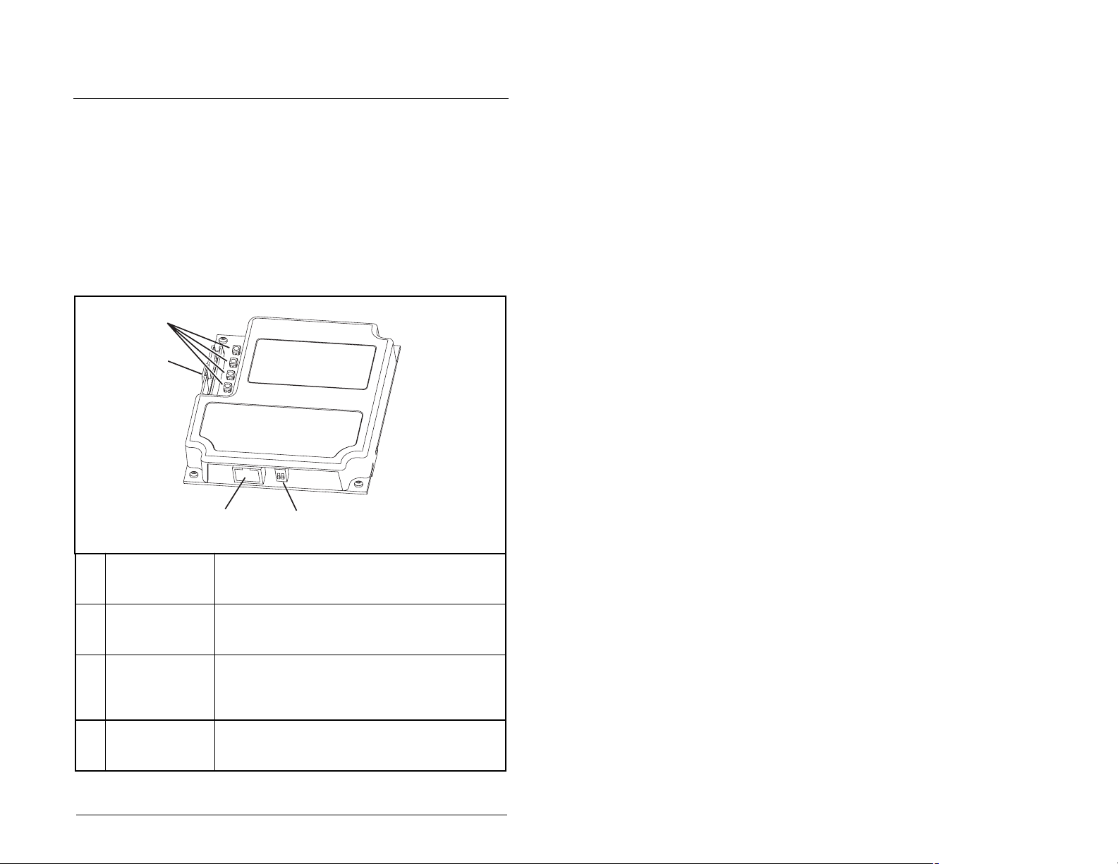
Status Indicators Four LEDs to indicate the status of the connected
➀
DPI Connector A 20-pin, single-row shrouded male header. An
➁
Ethernet
➂
Connector
Web Page
④
Switch (SW2)
Figure 2.1 – Components of the EtherNet/IP Module
Getting Started
drive, module, and network. Refer to chapter 6 for
more information about the LEDs.
Internal Interface cable connects to this connector
and one on the drive.
An RJ-45 connector the Ethernet cable. The
connector is CAT-5 compliant to ensure reliable
data transfer on 100Base-TX Ethernet
connections.
Enables or disables the module web pages. Refer
to Chapter 3, Setting the Web Pages Switch
(Firmware 3.xxx only). SW1 is unused.
Not provided on
firmware version 2.xxx
or earlier
2-1
Page 18

2.1 Required Equipment
Table 2.1 lists the equipment shipped with the EtherNet/IP module.
When you unpack the module, verify that the package includes all of
these items.
Table 2.1 – Equipment Shipped with the EtherNet/IP Module
Item Description
One EtherNet/IP Communications module
One 2.54 cm (1 in) and one 15.24 cm (6 in) Internal Interface cable
(only one of these cables is needed to connect the module to the
drive)
One EtherNet/IP Communications module User Manual (D2-3510)
To install and configure the EtherNet/IP module, you must supply
the items listed in table 2.2.
Table 2.2 – User-Supplied Items Required for Installation
Item Description
Small flathead or Phillips screwdriver
Ethernet cable (Refer to the EtherNet/IP Media Planning and
Installation Manual, publication ENET-IN001..., for details.)
Configuration tool, such as
• SP600 LCD OIM, GV6000 LCD OIM, or LiquiFlo 2.0 LCD OIM
• VS Utilities
• BOOTP Server (version 2.1 or higher) for network setup only
Controller configuration software (for example: RSLogix 5,
RSLogix 500, RSLogix 5000 software)
PC connection to the EtherNet/IP network.
2-2
EtherNet/IP Communcations Module
Page 19

2.2 Installation Checklist
This section is designed to help experienced users start using the
EtherNet/IP module. If you are unsure how to complete a step, refer
to the referenced chapter.
✔
Step Action Refer to:
1 Review the safety precautions for the
❒
❒
❒
❒
❒
❒
module.
2 Verify that the drive is properly installed.
3Install the module.
Verify that the drive and the network are not
powered. Then, connect the module to the
network using an Ethernet cable and to the
drive using the Internal Interface cable. Use
the captive screws to secure and ground
the module to the drive.
4 Apply power to the module.
Apply power to the network and to the drive.
The module receives power from the drive
and network. The status indicators should
be green. If they flash red, there is a
problem. Refer to chapter 8 for more
information on the status indicators.
5 Configure the module for your
application.
Set the parameters for the following
features as required by your application:
• IP address, subnet mask, and gateway
address
• Data rate
• I/O configuration
• Master-slave or peer-to-peer hierarchy
• Fault actions
6 Configure the scanner or bridge to
communicate with the module.
Use a software tool, such as RSLogix, to
configure the master on the EtherNet/IP
network to recognize the module and the
drive.
Throughout
this manual
Drive User
Manual
Chapter 3,
Installing the
EtherNet/IP
module
Chapter 3,
Installing the
EtherNet/IP
module
Chapter 4,
Configuring the
EtherNet/IP
module
Chapter 5,
Configuring the
Scanner or
Bridge
Getting Started
2-3
Page 20

✔
Step Action Refer to:
7 Create a ladder logic program.
❒
Use a programming tool to create a ladder
logic program that enables you to do the
following:
• Control the module and connected drive
using I/O
• Monitor or configure the drive using
Explicit messages.
Chapter 6,
Using I/O
Messaging
Chapter 7,
Using Explicit
Messaging
2-4
EtherNet/IP Communcations Module
Page 21

CHAPTER 3
Installing the
EtherNet/IP Module
Chapter 3 provides instructions for installing the module on
Reliance Electric drives.
3.1 Preparing for an Installation
Before installing the module:
• Read the EtherNet/IP Performance and Application Guide,
publication ENET-AP001..., and EtherNet/IP Media Planning and
Installation Manual, publication ENET-IN001...
• Verify that you have all required equipment. Refer to chapter 2,
Getting Started, for a list of equipment.
ATTENTION: The EtherNet/IP module contains
ESD- (Electrostatic Discharge) sensitive parts that
!
can be damaged if you do not follow ESD control
procedures. Static control precautions are required
when handling the module. Failure to observe these
precautions could result in damage to equipment.
Important: To guard against device malfunction, you must wear a
grounding wrist strap when installing the EtherNet/IP
module.
3.2 Setting the Web Pages Switch
(Version 3.xxx)
To use the module web pages, the Web Pages Switch (not provided
on version 2.xxx and earlier modules) must be set to its “Enable
Web” position.
Important: A new setting is recognized only when power is
applied to the module, or the module is reset. If you
change a setting, cycle power or reset the module.
Installing the EtherNet/IP Module
3-1
Page 22
ATTENTION: The EtherNet/IP module contains
ESD- (Electrostatic Discharge) sensitive parts that
!
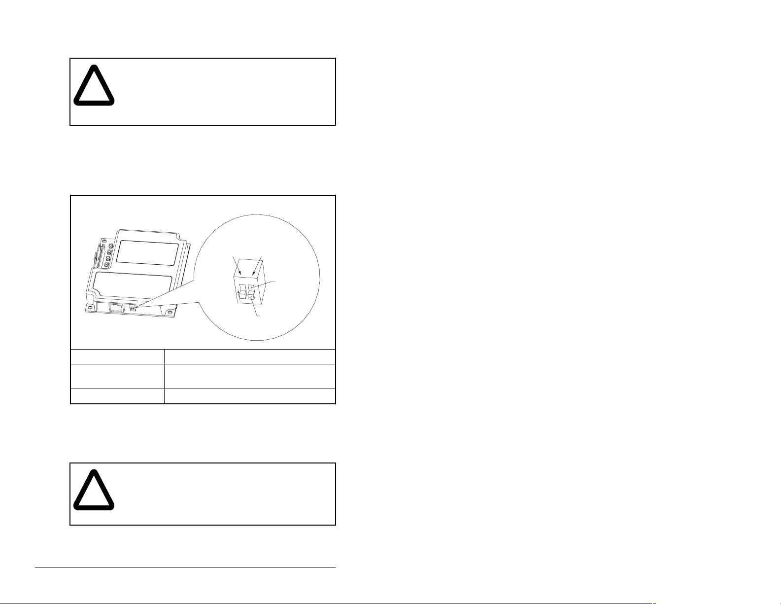
Set the Web Pages Switch (SW2) to enable or disable the module
web pages (see figure 3.1 and setting descriptions below). By
default, the module web pages are disabled. For complete details
on module web pages, see Chapter 9, View the module’s Web
Pages.
can be damaged if you do not follow ESD control
procedures. Static control precautions are required
when handling the module. Failure to observe these
precautions could result in damage to equipment.
UNUSED
SWITCH
SW2 Setting Description
Down (OFF) position Disables the module web pages (default
setting).
Up (ON) position Enables the module web pages.
Figure 3.1 – Setting Web Pages Switch
O
1
N
WEB PAGES
SWITCH
2
Disable Web
Position
Enable Web
Position
3.3 Connecting the Module to the Drive
ATTENTION: The Reliance Electric drive may
contain high voltages that can cause injury or death.
!
Remove power from the drive, and then verify power
has been discharged before installing or removing
an module . Failure to observe this precaution could
result in severe bodily injury or loss of life.
3-2
Step 1. Remove power from the drive.
Step 2. Use static control precautions.
EtherNet/IP Communications Module
Page 23
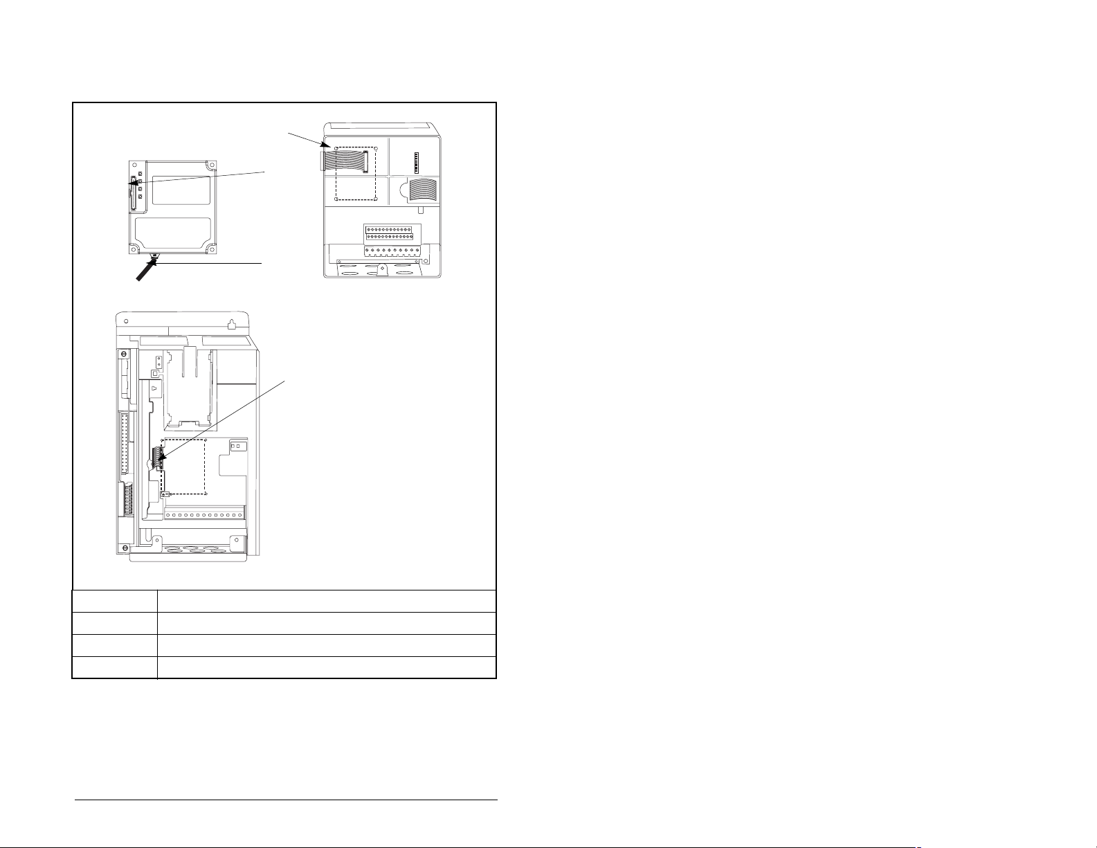
Step 3. Connect the Internal Interface cable to the DPI port on the
drive and then to the DPI connector on the module. See
figure 3.2.
➀
➁
➂
EtherNet/IP module
SP600 Drive
(6SP Series)
➃
GV6000 or SP600 6SB Series Drive
➀
➁
➂
➃
Installing the EtherNet/IP Module
15.24 cm (6 in) Internal Interface cable
DPI Connector
EtherNet Cable
2.54 cm (1 in) Internal Interface cable
Figure 3.2 – DPI Ports and Internal Interface Cables
Step 4. For SP600 6SP Series drives, fold the Internal Interface
cable behind the module and mount the module on the
drive using the four captive screws. See figure 3.3.
3-3
Page 24
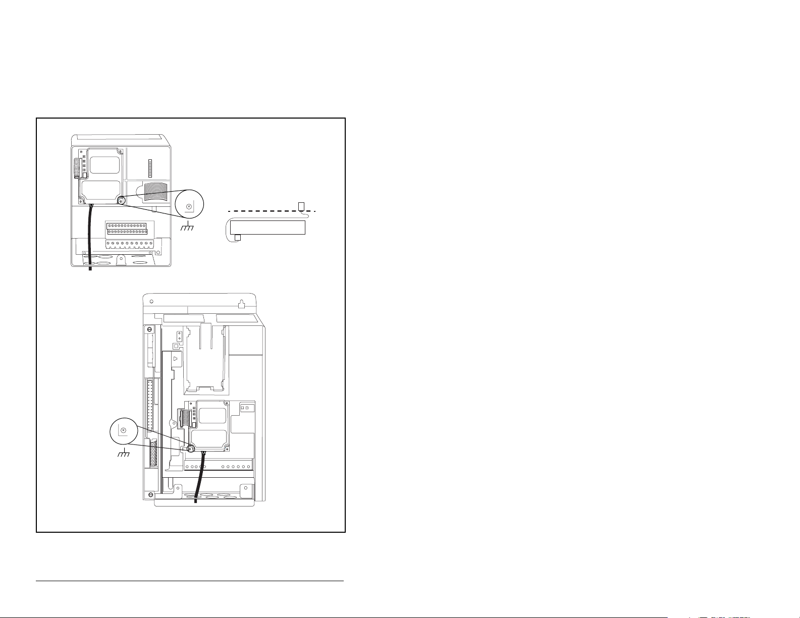
For GV6000 and SP600 6SB series drives, mount the
module on the drive using the four captive screws to
secure and ground it to the drive.
Important: All screws must be tightened since the module is
grounded through a screw. The recommended
tightening torque is 0.9 N-m (8 in-lb).
Module
Internal Interface cable
folded behind the module
and in front of the drive.
SP600 6SP Series Drive
3-4
GV6000 or SP600 6SB Series Drive
Figure 3.3 – Mounting the Module
EtherNet/IP Communications Module
Page 25
3.4 Connecting the Module to the
Network
ATTENTION: The Reliance Electric drive may
contain high voltages that can cause injury or death.
Remove power from the drive, and then verify power
!
has been discharged before installing or removing
a module. Failure to observe this precaution could
result in severe bodily injury or loss of life.
Step 1. Remove power from the drive.
Step 2. Use static control precautions.
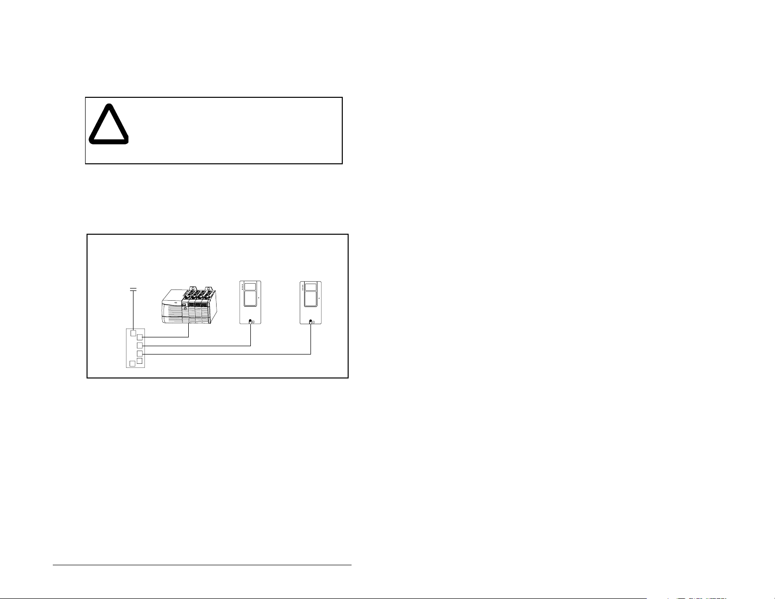
Step 3. Connect an Ethernet cable to the EtherNet/IP network.
Refer to figure 3.4.
SP600
Drive
Router
(Optional)
Figure 3.4 – Connecting the Ethernet Cable to the Network
Step 4. Route the Ethernet cable through the bottom of the
drive and connect it to the module.
Step 5. Connect the cable to the module (refer to figure 3.2).
ControlLogix with
EtherNet/IP Bridge
with
RECOMM-ENET
GV6000
Drive
with
RECOMM-ENET
Installing the EtherNet/IP Module
3-5
Page 26

3.5 Applying Power
ATTENTION: Unpredictable operation may occur
if parameter settings are not compatible with your
!
Step 1. Close the door or reinstall the cover on the drive. The
Step 2. Apply power to the drive. The module receives its power
application. Verify that settings are compatible with
your application before applying power to the drive.
Failure to observe these precautions could result
in severe bodily injury of loss of life.
status indicators can be viewed on the front of the drive
after power has been applied.
from the connected drive. When you apply power to the
product for the first time, the status indicators should be
green or off after an initialization. If the status indicators
are red, refer to chapter 8, Troubleshooting the module
and Network.
3.6 Commissioning the Module
To commission the module, you must set a unique IP address.
(Refer to the Glossary for details about IP addresses.) After
installing the module and applying power, you can set the IP
address by using a BOOTP server or by setting parameters.
3-6
By default, the module is configured so that you must set the IP
address using a BOOTP server. To set the IP address using
parameters, you must disable the BOOTP feature. Refer to chapter
4, Configuring the module, for details.
Important: New settings for some parameters (for example, IP
Addr Cfg 1 through IP Addr Cfg 4) are recognized only
when power is applied to the module or it is reset.
After you change parameter settings, cycle power or
reset the module.
EtherNet/IP Communications Module
Page 27

CHAPTER 4
Configuring the
EtherNet/IP Module
Chapter 4 provides instructions and information for setting the
parameters in the module.
For a complete list of parameters, refer to Appendix B, EtherNet/IP
Module Parameters. For definitions of terms in this chapter, refer to
the Glossary.
4.1 Configuration Tools
The module stores parameters and other information in its own nonvolatile memory. Therefore, you must access the module to view
and edit its parameters. Table 4.1 lists the tools that can be used to
access the module parameters.
Table 4.1 – Configuration Tools
Too l Refe r t o :
VS Utilities Software VS Utilities online help
LCD OIM Section 4.2
BOOTP Server Section 4.3
Configuring the EtherNet/IP Module
4-1
Page 28
4.2 Using the LCD OIM to Configure the
Module
4.2.1 SP600 and LiquiFlo 2.0
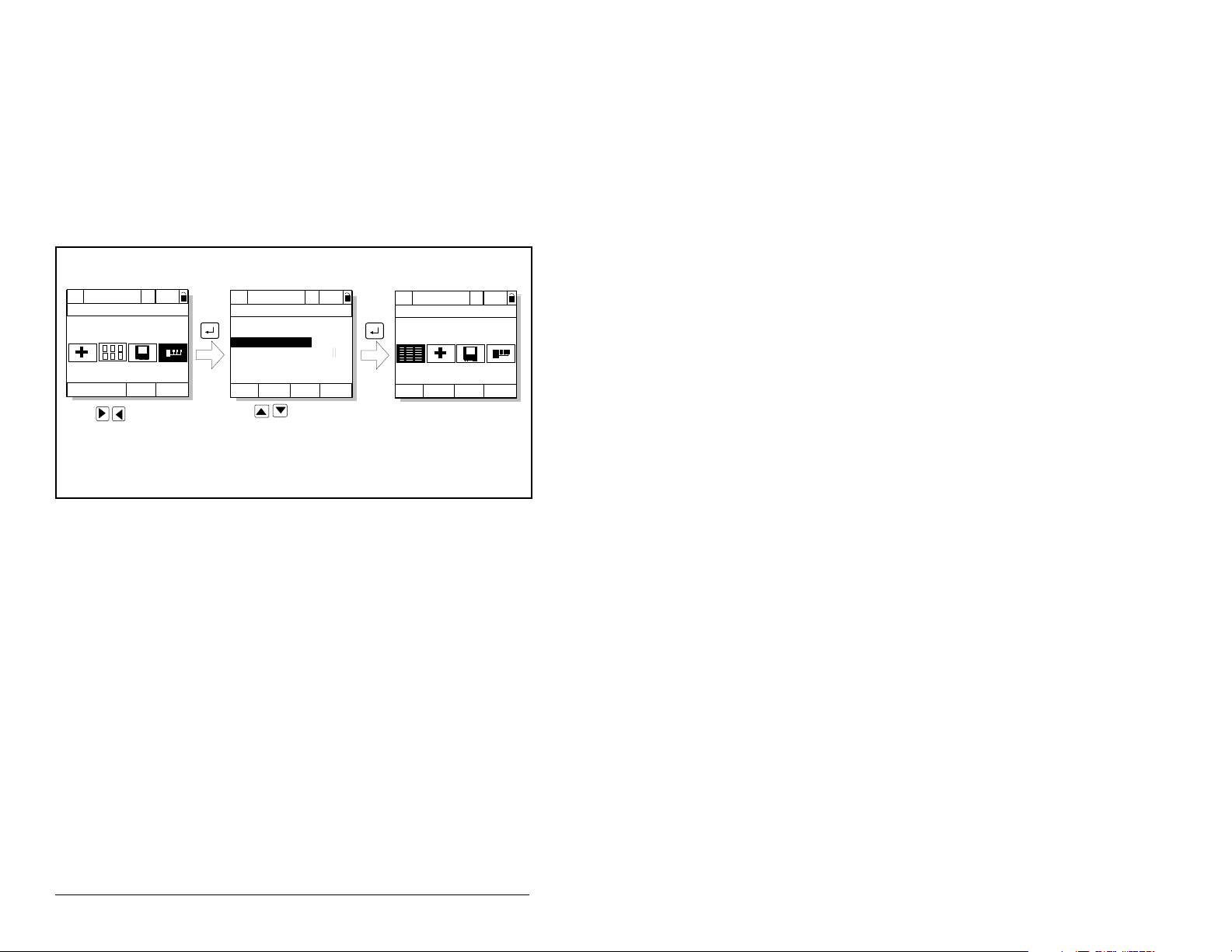
Use the procedure in figure 4.1 to access the parameters on the
EtherNet/IP module using the LCD OIM. If you are unfamiliar with
the operation of the LCD OIM, refer to the Reliance Electric Drive
User Manual for more information.
>>
Stopped
P0: SP600
Main Menu
Device Sele ct
Monitor
Use to highlight
Device Select icon
Auto
Lang
>>
Stopped
P0: SP600
Device: Port 0
SP600
RECOMM-ENE T
Auto
Use to select
RECOMM-ENET.
>>
Stopped
P5: RECOMM-ENET
Main Menu
Parameters
Auto
Edit the EtherNet/IP
parameters using the
same techniques as for
drive parameters.
Figure 4.1 – Accessing the Module Parameters using the LCD OIM (SP600, LiquiFlo)
4-2
EtherNet/IP Communications Module
Page 29
4.2.2 GV6000
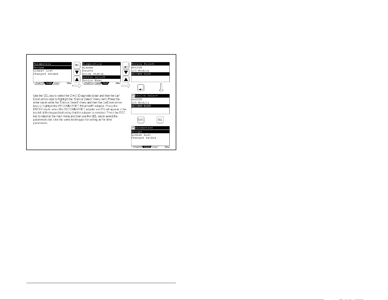
Use the procedure in figure 4.2 to access the parameters on the
EtherNet/IP module using the LCD OIM. If you are unfamiliar with
the operation of the LCD OIM, refer to the Reliance Electric Drive
User Manual for more information.
Figure 4.2 – Acessing the Module Parameters using the LCD OIM (GV6000)
4.3 Using BOOTP to Set the IP Address,
Subnet Mask, and Gateway Address
By default, the module is configured so that you can set its IP
address, subnet mask, and gateway address by using a BOOTP
utility. You can select from a variety of BOOTP utilities. These
instructions use Rockwell’s BOOTP Server (version 2.1), a standalone program that incorporates the functionality of standard
BOOTP utilities with a graphical interface. It is available from
http://www.reliance.com. Refer to the Readme file and online Help
for detailed directions and information.
Note: If desired, you can disable BOOTP and configure the IP
address, subnet mask, and gateway address by setting parameters.
For details, refer to section 4.4.
To configure the module using BOOTP Server, use the following
procedure:
Step 1. On the label of the module, locate and note the hardware
address of the module.
Configuring the EtherNet/IP Module
4-3
Page 30
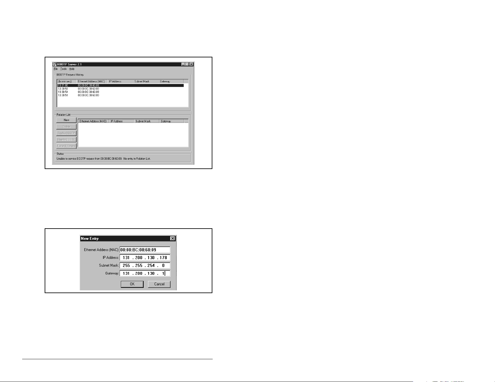
Step 2. On a computer connected to the EtherNet/IP network,
start the BOOTP software. The BOOTP Server window
appears as shown in figure 4.3. Devices on the network
issuing BOOTP requests appear in the BOOTP Request
History list.
Figure 4.3 – BOOTP Server Window
Step 3. In the BOOTP Request History list, double-click the
hardware address (Ethernet MAC address) of the module.
The New Entry dialog box is displayed as shown in figure
4.4.
4-4
Figure 4.4 – New Entry Dialog Box
Step 4. Edit the fields shown in table 4.2 in the New Entry Dialog
box:
EtherNet/IP Communications Module
Page 31

Table 4.2 – Editing the New Entry Dialog Box
In this field: Enter this information:
IP Address
1
Subnet Mask
Gateway
1
1
For definitions, refer to the Glossary.
A unique IP address for the module.
1
A subnet mask for the module’s network.
The IP address of the gateway device on the
module’s network.
Step 5. Click OK to apply the settings. The module appears in the
Relation List with the new settings as shown in figure 4.5.
Figure 4.5 – BOOTP Server Window with an Module in the Relation List
Step 6. To assign this configuration to the module permanently,
click Disable BOOTP. When power is cycled on the
module, it will use the configuration you assigned it and
will not issue new BOOTP requests.
Note: To enable BOOTP for a module that has had
BOOTP disabled:
a. Select the module in the Relation List
b. Click Enable BOOTP.
c. Reset the module.
Step 7. To save the Relation List, select File > Save.
Configuring the EtherNet/IP Module
4-5
Page 32

4.4 Using Parameters to Set the IP
Address, Subnet Mask, and Gateway
Address
By default, the module is configured so that you set its IP address,
subnet mask, and gateway address using a BOOTP server. If you
want to set these features using the module’s parameters instead,
you must disable BOOTP and then set the appropriate parameters
in the module.
To disable the BOOTP feature:
Step 1. Set the value of module parameter 3 (BOOTP) to
Disabled as shown in figure 4.6.
Por t 5 Device
RECOMM-ENET
Parameter #: 03
BOOTP
0
Disabled
Figure 4.6 – Sample BOOTP Screen on an LCD OIM
Val ue Setting
0 Disabled
1 Enabled (Default)
Step 2. Reset the module. Refer to Resetting the Module in
section 4.11.
After disabling the BOOTP feature, you can then configure the IP
address, subnet mask, and gateway using the module’s parameters.
To set an IP address using parameters:
Step 1. Verify that module parameter 3 (BOOTP) is set to
Disabled. This parameter must be set to Disabled to
configure the IP address using parameters.
Step 2. Set the value of module parameters 4 through 7 (IP Addr
Cfg 1 through IP Addr Cfg 4) to a unique IP address.
Port 5 Device
RECOMM-ENET
Parameter #: 04
IP Addr Cfg 1
0
0 <> 255
Default = 0.0.0.0 255 . 255 . 255 . 255
[IP Addr Cfg 1]
[IP Addr Cfg 2]
[IP Addr Cfg 3]
[IP Addr Cfg 4]
4-6
Figure 4.7 – Sample IP Address Screen on an LCD OIM
EtherNet/IP Communications Module
Page 33

Step 3. Reset the module. Refer to Resetting the Module in
section 4.11.
The Net A status indicator will be solid green or flashing green if the
IP address is correctly configured.
To set a subnet mask using parameters:
Step 1. Verify that module parameter 3 (BOOTP) is set to
Disabled. This parameter must be set to Disabled to
configure the subnet mask using parameters.
Step 2. Set the value of module parameters 8 through 11 (Subnet
Cfg 1 through Subnet Cfg 4) to the desired value for the
subnet mask as shown in figure 4.8.
Por t 5 Devic e
RECOMM-ENET
Parameter #: 08
Subnet Cfg 1
0
0 <> 255
Figure 4.8 – Sample Subnet Mask Screen on an LCD OIM
Default = 0.0.0.0 255 . 255 . 255 . 255
[Subnet Cfg 1]
[Subnet Cfg 2]
[Subnet Cfg 3]
[Subnet Cfg 4]
Step 3. Reset the module. Refer to Resetting the Module in
section 4.11.
To set a gateway address for the module using parameters
Step 1. Verify that module parameter 3 (BOOTP) is set to
Disabled. This parameter must be set to Disabled to
configure the gateway address using parameters.
Step 2. Set the value of module parameters 12 through 15
(Gateway Cfg 1 through Gateway Cfg 4) to the IP address
of the gateway device as shown in figure 4.9.
Port 5 Device
RECOMM-ENET
Parameter #: 12
Gateway Cfg 1
0
0 <> 255
Default = 0.0.0.0 255 . 255 . 255 . 255
[Gateway Cfg 1]
[Gateway Cfg 2]
[Gateway Cfg 3]
[Gateway Cfg 4]
Figure 4.9 – Sample Gateway Screen on an LCD OIM
Step 3. Reset the module. Refer to Resetting the Module in
section 4.11.
Configuring the EtherNet/IP Module
4-7
Page 34

4.5 Setting the Data Rate
By default, the module is set to autodetect, so it automatically
detects the data rate and duplex setting used on the network. If you
need to set a specific data rate and duplex setting, the value of
module parameter 16 (EN Rate Cfg) determines the Ethernet data
rate and duplex setting that the module will use to communicate. For
definitions of data rate and duplex, refer to the Glossary.
Step 1. Set the value of parameter 16 (EN Rate Cfg) to the data
rate at which your network is operating as shown in figure
4.10.
Por t 5 Devi ce
RECOMM-ENET
Parameter #: 16
EN Rate Cfg
0
Autodetect
Figure 4.10 – Ethernet Data Rate Screen on an LCD OIM
Valu e Dat a Rate
0 Autodetect (default)
110 Mbps Full
210 Mbps Half
3 100 Mbps Full
4 100 Mbps Half
Important:Auto detection of baud rate and duplex works properly
only if the device (usually a switch) on the other end of
the cable is also set to auto detect the baud rate/duplex.
If one device has the baud rate/duplex hard coded, the
other device must be hard-coded to the same settings.
Step 2. Reset the module. Refer to Resetting the Module in
section 4.11.
4.6 Setting the I/O Configuration
The I/O configuration determines the data that is sent to and from
the drive. Logic Command/Status, Reference/Feedback and
Datalinks may be enabled or disabled.
Step 1. Set the bits in module parameter 23 (DPI I/O CFG) as
shown in figure 4.11. A “1” enables the I/O. A “0” disables
the I/O. Bit 0 is the right-most bit. In figure 4.11, it is
highlighted and equals “1”.
4-8
EtherNet/IP Communications Module
Page 35

Por t 5 Device
RECOMM-ENET
Parameter #: 23
DPI I/O Config
xxxxxxxxxxx0000
Cmd/Ref b00
Figure 4.11 – I/O Configuration Screen on an LCD OIM
Bit Description
0 Logic Command/Reference (Default)
1Datalink A
2Datalink B
3Datalink C
1
4Datalink D
5 - 15 Not Used
Step 2. If Logic Command/Reference is enabled, configure the
parameters in the drive to accept the Logic Command
and Reference from the module. For example, set Speed
Ref A Sel (90) in the drive to “Network” so that the drive
uses the Reference from the module. Also, verify that
drive parameter Logic Source Sel (89) is configured to
receive the desired logic from the module. Refer to the
drive documentation for details.
Step 3. If you enabled one or more Datalinks, configure
parameters in the drive to determine the source and
destination of data in the Datalink(s). For example,
configure the Datalinks in the drive by setting parameters
300 through 317 (Data In A1 through Data Out D2). Also,
ensure that the EtherNet/IP module is the only module
using the enabled Datalink(s).
Step 4. Reset the module. Refer to section 4.11, Resetting the
Module.
The module is ready to receive I/O. You must now configure the
module to receive I/O from a master or peer device. Refer to section
4.8, Selecting a Master-Slave or Peer-to-Peer Hierarchy. If you
select a Master-Slave hierarchy, you must also configure the master
to communicate with the module. Refer to chapter 5, Configuring
the Scanner or Bridge.
Configuring the EtherNet/IP Module
4-9
Page 36

4.7 Setting the Reference Adjustment
A reference adjustment is a percent scaling factor for the reference
from the network and can be set from 0 to 200%. This allows the
drive’s reference to either match the network reference (=100%),
scale below the network reference (<100%), or scale above the
network reference (>100%).
ATTENTION: Changes to module parameter 37 (Ref
Adjust) take effect immediately. A drive receiving its
!
If the module is receiving a reference, adjust the scale in module
parameter 37 (Ref Adjust). It can be scaled between 0.00 and
200.00%. Refer to figure 4.12.
Reference from the module will receive the newly
scaled Reference, resulting in a change of speed.
Failure to observe this precaution could result in
bodily injury or damage to equipment.
Por t 5 Devi ce
RECOMM-ENET
Parameter #: 37
Ref Adjust
100.00 %
0.00 <> 200.00
Figure 4.12 – Reference Adjust Screen on an LCD OIM
The adjustment takes effect as soon as it is entered.
Default = 100.00%
4.8 Selecting a Master-Slave or Peer-toPeer Hierarchy
A hierarchy determines the type of device with which the module
exchanges data. In a Master-Slave hierarchy, a module exchanges
data with a master, such as a scanner or bridge. In a Peer-to-Peer
hierarchy, a module exchanges data with one or more EtherNet/IP
modules connected to devices that have compatible logic
command/status words.
For both master-slave and peer-to-peer hierarchies, the devices
exchanging data must be on the same IP subnet. See “IP
Addresses” in the Glossary for more information about IP subnets.
4-10
EtherNet/IP Communications Module
Page 37

4.8.1 Configuring the Module for a Master-Slave
Hierarchy
To select a Master-Slave hierarchy:
Step 1. Enable the desired I/O in module parameter 23 (DPI I/O
Step 2. Set the bits in module parameter 35 (M-S Input). This
Cfg). Refer to figure 4.11.
parameter determines the data received from the master
by the drive. A “1” enables the I/O. A “0” disables the I/O.
Bit 0 is the right-most bit. In 4.13, it is highlighted and
equals “1.”
Port 5 Device
RECOMM-ENET
Parameter #: 35
M-S Input
xxxx xxxx xxx0 000
Cmd/Ref b00
Figure 4.13 – Master-Slave Input Screen on an LCD OIM
Bit Description
0 Logic Command/Reference (Default)
1 Datalink A Input
2 Datalink B Input
3 Datalink C Input
1
4 Datalink D Input
5 - 15 Not Used
Step 3. Set the bits in module parameter 36 (M-S Output). This
parameter determines the data transmitted from the drive
to the scanner. A “1” enables the I/O. A “0” disables the
I/O. Bit 0 is the right-most bit. In figure 4.14, it is
highlighted and equals “1.”
.
Port 5 Device
RECOMM-ENET
Parameter #: 36
M-S Output
xxxxxxxxxxx0000
Status/Fdbk b00
Figure 4.14 – Master-Slave Output Screen on an LCD OIM
Bit Description
0 Status/Feedback (Default)
1 Datalink A Output
2 Datalink B Output
3 Datalink C Output
1
4 Datalink D Output
5 - 15 Not Used
Step 4. Reset the module. Refer to Resetting the Module in
section 4.11.
The module is ready to receive I/O from the master (i.e., scanner).
You must now configure the scanner to recognize and transmit I/O
to the module. Refer to chapter 5, Configuring the Scanner or
Bridge.
Configuring the EtherNet/IP Module
4-11
Page 38

4.8.2 Configuring the Module to Transmit Peer-toPeer Data
To configure an module to transmit Peer-to-Peer data:
Step 1. Verify that module parameter 51 (Peer Out Enable) is set
to Off (see figure 4.15). This parameter must be Off while
you configure peer output parameters.
Por t 5 Device
RECOMM-ENET
Parameter #: 51
Peer Out Enable
0
Off
Figure 4.15 – Peer Out Enable Screen on an LCD OIM
Value Setting
0 Off (Default)
1On
Step 2. Select the source of the data to output to the network in
module parameter 49 (Peer A Output). See figure 4.16.
Por t 5 Device
RECOMM-ENET
Parameter #: 49
Peer A Output
1
Cmd/Ref
Figure 4.16 – Peer A Output Screen on an LCD OIM
Value Description
0 Off (Default)
1 Logic Command/Reference
2 - 5 Datalink A, B, C, or D Input
6 - 9 Datalink A, B, C, or D Output
Step 3. If desired, select an additional source of the data to output
to the network in module parameter 50 (Peer B Output) as
shown in figure 4.17.
4-12
Por t 5 Device
RECOMM-ENET
Parameter #: 50
Peer B Output
2
DL A Input
Figure 4.17 – Peer B Output Screen on an LCD OIM
Value Description
0 Off (Default)
1 Logic Command/Reference
2 - 5 Datalink A, B, C, or D
Input
6 - 9 Datalink A, B, C, or D
Output
Step 4. Set module parameters 52 (Peer Out Time) and 53 (Peer
Out Skip) to establish the minimum and maximum
intervals between Peer messages. Because the module
EtherNet/IP Communications Module
Page 39

transmits Peer messages when a change-of-state
condition occurs, minimum and maximum intervals are
required.
• The minimum interval ensures that the module does
not transmit messages on the network too often, thus
minimizing network traffic. It is set in module
parameter 52 (Peer Out Time).
• The maximum interval ensures that the module
transmits messages often enough so that the
receiving module(s) can receive recent data and verify
that communications are working or, if
communications are not working, can timeout. The
maximum interval is the value of module parameter 52
(Peer Out Time) multiplied by the value of module
parameter 53 (Peer Out Skip).
In the example in figure 4.18, the minimum interval is set
to 2.00 seconds, and the maximum interval is set to 4.00
seconds (2.00 x 2).
Por t 5 Device
RECOMM-ENET
Parameter #: 52
Peer Out Time
2.00 Secs.
0 <> 10.00
Figure 4.18 – Peer Out Time and Peer Out Skip Screens on an LCD OIM
Default =
10.00 Secs
Port 5 Device
RECOMM-ENET
Parameter #: 53
Peer Out Skip
2
1 <>16
Default = 1
Step 5. Set module parameter 51 (Peer Out Enable) to On. The
module will transmit the data selected in module
parameters 49 (Peer A Output) and 50 (Peer B Output) to
the network. Another module must be configured to
receive the peer I/O data.
4.8.3 Configuring the Module to Receive Peer-toPeer Data
To configure the module to receive Peer-to-Peer data:
Step 1. Verify that module parameter 47 (Peer Inp Enable) is set
to Off (see figure 4.19). This parameter must be set to Off
while you configure the peer input parameters.
Configuring the EtherNet/IP Module
4-13
Page 40

Port 5 Device
RECOMM-ENET
Parameter #: 47
Peer Inp Enable
0
Off
Figure 4.19 – Peer Input Enable Screen on an LCD OIM
Value Setting
0 Off (Default)
1On
Step 2. In module parameters 42 through 45 (Peer Inp Addr 1
through Peer Inp Addr 4), set the IP address of the node
from which you want to receive data. See figure 4.20.
Valid nodes must have EtherNet/IP modules connected to
drives with compatible logic command/status words.
Por t 5 Device
RECOMM-ENET
Parameter #: 42
Peer Inp Addr 1
0
0 <> 255
Figure 4.20 – Peer Input Address 1 Screen on an LCD OIM
IP Address of Node Transmitting
Peer I/O
Default = 0.0.0.0
[Peer Inp Addr 1]
255 . 255 . 255 . 255
[Peer Inp Addr 2]
[Peer Inp Addr 3]
[Peer Inp Addr 4]
Step 3. Select the destination of the data that is input to the drive
as Peer A in module parameter 38 (Peer A Input). See
figure 4.21.
Por t 5 Device
RECOMM-ENET
Parameter #: 38
Peer A Input
1
Cmd/Ref
Figure 4.21 – Peer A Input Screen on an LCD OIM
Value Description
0 Off (Default)
1 Logic Command/Reference
2 - 5 Datalink A, B, C, or D
Input
If you select a Reference or Datalink as an input, note the
following:
• If a drive that uses a 32-bit Reference and 32-bit
Datalinks receives a 16-bit Reference or Datalink, it
uses the data in its most significant word, and its least
significant word is zero.
4-14
EtherNet/IP Communications Module
Page 41

• If a drive that uses a 16-bit Reference and 16-bit
Datalinks receives a 32-bit Reference or Datalink, it
uses the data in the most significant word of the 32-bit
Reference or Datalink and ignores the data in the least
significant word.
Step 4. If desired, select the destination of the data to input to the
drive as Peer B in module parameter 39 (Peer B Input).
See figure 4.22.
Port 5 Device
RECOMM-ENET
Parameter #: 39
Peer B Input
2
DL A Input
Figure 4.22 – Peer B Input Screen on an LCD OIM
Value Description
0 Off (Default)
1 Logic Command/Reference
2 - 5 Datalink A, B, C, or D
Input
Step 5. If the module receives a Logic Command, set the bits in
module Peer Cmd Mask (40) that the drive should use.
See figure 4.23. The bit definitions for the Logic
Command word will depend on the drive to which the
module is connected. Refer to Appendix D or drive
documentation.
Por t 5 Device
RECOMM-ENET
Parameter #: 40
Peer Cmd Mask
000000000000000
Bit 0 B00
Figure 4.23 – Peer Logic Command Mask Screen on an LCD OIM
Value Description
0 Ignore this command bit.
(Default)
1 Use this command bit.
0
If the module receives a Logic Command from both a
Master device and a Peer device, each command bit must
have only one source. The source of command bits set to
“0” will be the Master device. The source of command bits
set to “1” will be the Peer device.
Step 6. Set module Peer Inp Timeout (46) to the maximum
amount of time the module will wait for a message before
timing out. See figure 4.24.
Important:This value must be greater than the product of Peer Out
Time (52) multiplied by Peer Out Skip (53) in the module
from which you are receiving I/O.
Configuring the EtherNet/IP Module
4-15
Page 42

For example, if the value of Peer Out Time (52) is 2.00
and the value of Peer Out Skip (53) is 2 (see figure 4.18),
then parameter 46 (Peer Inp Timeout) needs to have a
value greater than 4.00, such as 5.00 (see figure 4.24).
Port 5 Device
RECOMM-ENET
Parameter #: 46
Peer Inp Timeout
5.00 Secs.
0.01 <> 10.00
Figure 4.24 – Peer Input Timeout Screen on an LCD OIM
Default = 10.00 Secs
Step 7. Set the action in parameter 41 (Peer Flt Action) that the
module will take if it times out. Figure 4.25 shows the Peer
Flt Action Screen on an LCD OIM. Refer to section 4.9 for
more information about setting fault actions.
ATTENTION: Peer Flt Action (41) lets you determine
the action of the module and connected drive if the
.
!
module times out
the drive if you have configured the module for peer-
By default, this parameter faults
to-peer communication. You can set this parameter
so that the drive continues to run. Precautions should
be taken to ensure that the setting of this parameter
does not create a hazard of injury or equipment
damage. When commissioning the drive, verify that
your system responds correctly to various situations.
Failure to observe this precaution could result in
bodily injury and/or damage to equipment.
4-16
Port 5 Device
RECOMM-ENET
Parameter #: 41
Peer Flt Action
0
Fault
Figure 4.25 – Peer Fault Action Screen on an LCD OIM
Value Description
0 Fault (Default)
1Stop
2Zero Data
3 Hold Last
4 Send Flt Cfg
Step 8. Set module parameter 47 (Peer Inp Enable) to On.
Step 9. Reset the module. Refer to section 4.11, Resetting the
module. The module is now configured to receive Peer
I/O from the specified node. Ensure that the specified
node is configured to transmit Peer I/O.
EtherNet/IP Communications Module
Page 43

4.9 Setting a Fault Action
There are three user-configurable fault action parameters:
Comm Flt Action (21) and Idle Flt Action (22) determine the action
of the module and the connected drive if communications are
disrupted. By default, these parameters fault the drive if it is using I/
O from the network and communications are disrupted (for example,
a cable is disconnected) or the master is idle.
Peer Flt Action (41) determines the action of the module and the
connected drive if the module times out. By default, this parameter
faults the drive if the module has been configured for peer-to-peer
communications and the module times out.
Table 4.3 lists the response selections for these parameters.
Changes to these parameters take effect immediately. A reset is not
required.
See figure 4.26 for sample LCD OIM Comm Flt Action and Idle Flt
Action screens. See figure 4.25 for a sample LCD OIM Peer Flt
Action Screen.
ATTENTION: Comm Flt Action (21) and Idle Fault
Action (22) let you determine the action of the module
!
and connected drive if communications are
disrupted or the controller is idle. By default, these
parameters fault the drive. You can set the
parameters so that the drive continues to run.
Precautions should be taken to ensure that the
setting of these parameters does not create a risk of
injury or equipment damage. When commissioning
the drive, verify that your system responds correctly
to various situations (e.g., a disconnected cable or
faulted controller). Failure to observe this precaution
could result in bodily injury and/or damage to
equipment.
Configuring the EtherNet/IP Module
4-17
Page 44

ATTENTION: Parameter 41 (Peer Flt Action) lets
you determine the action of the module and
.
!
connected drive if the module times out
this parameter faults the drive if you have configured
By default,
the module for peer-to-peer communication. You can
set this parameter so that the drive continues to run.
Precautions should be taken to ensure that the
setting of this parameter does not create a hazard of
injury or equipment damage. When commissioning
the drive, verify that your system responds correctly
to various situations (for example, a disconnected
cable). Failure to observe this precaution could result
in bodily injury and/or damage to equipment.
Table 4.3 – Selections for Drive Response to Communication Fault
Value Action Description
0 Fault (default) The drive is faulted and stopped (Default).
1 Stop The drive is stopped, but not faulted.
2 Zero Data The drive is sent 0 for output data after a
communications disruption. This does not
command a stop.
3 Hold Last The drive continues in its present state.
4 Send Flt Cfg The drive is sent the data that you set in
the fault configuration parameters, Flt Cfg
Logic (25) through Flt Cfg D2 In (34).
4-18
Port 5 Device
RECOMM-ENET
Parameter #: 21
Comm Flt Action
0
Fault
Figure 4.26 – Comm Flt Action Screen and Idle Flt Action Screen on an LCD
Port 5 Device
RECOMM-ENET
Parameter #: 22
Idle Flt Action
0
Fault
OIM
EtherNet/IP Communications Module
Page 45

4.9.1 Setting the Fault Configuration Parameters
If you set parameter 21 (Comm Flt Action), 22 (Idle Flt Action), or 14
(Peer Flt Action) to “Send Flt Cfg,” the values in the parameters
shown in table 4.4 are sent to the drive after a communications fault
occurs. You must set these parameters to values required by your
application.
Table 4.4 – Fault Configuration Parameters
Parameter
Number Name Description
25 Flt Cfg Logic A 16-bit value sent to the drive for Logic
26 Flt Cfg Ref A 32-bit value (0 to 4294967295) sent to
27 - 34 Flt Cfg x1 In
Flt Cfg x2 In
Changes to these parameters take effect immediately. A reset is not
required.
Command.
the drive as a Reference or Datalink.
Important: If the drive uses a 16-bit
Reference or 16-bit Datalinks, the most
significant word of the value must be set to
zero (0) or a fault will occur.
4.10 Setting Web Access Control
By accessing the IP address set for the adapter using a web
browser, you can view the module’s web pages for information
about the module, the Reliance Electric drive to which it is
connected, and other DPI devices connected to the drive such as
OIMs or serial adapters. Additionally, the module can be configured
to automatically send e-mail messages to desired addresses when
selected drive faults occur and/or are cleared, and/or when the
module takes a communication or idle fault action. For more details
on the modules’s web pages, refer to Chapter 9, Viewing the
Module’s Web Pages.
Important:Firmware 2.xxx (and earlier) module web pages are
accessed differently than 3.xxx web pages. Enabling/
disabling e-mail configuration is also different.
Configuring the EtherNet/IP Module
4-19
Page 46

Firmware 2.xxx (and earlier)
By default, the firmware 2.xxx (and earlier) module web pages are
enabled. To disable the module web pages, use Access Control (54)
to set the Web Enable Bit 0 value to “0” (Disabled). You can also
protect the configured settings for e-mail messaging using Access
Control (54). To do this, the value of E-mail Config Bit 1 must be“0”
(Disabled default). E-mail messaging will remain active regardless
of whether or not its settings are protected — unless e-mail
messaging was never configured.
Port 5 Device
RECOMM-ENET
Parameter #: 54
Access Control
xxxxxxxxxxxxxx0
Web Enable b00
Figure 4.27 – Example Web Access Control Screen on an LCD OIM
Bit Description
0 Web Enable (Default = 1 = enabled)
1 E-mail Config (Default = 0 = disabled)
2 - 31 Not Used
1
Changes to this parameter take effect immediately. A reset is not
required.
Firmware 3.xxx (and later)
By default, the firmware 3.xxx (and later) module web pages are
disabled. Refer to Figure 3.1 and set the Web Pages Switch (SW2)
to the “Enabled Web” (UP) position.
Important:For a change to the switch setting to take effect, the
module must be reset.
Bit 0 of Web Features (56) is used to protect the configured settings
for e-mail notification. By default, settings are not protected and the
user can make changes. To protect an e-mail configuration, set the
value of E-mail Cfg Bit 0 to “0” (Disabled). You can unprotect the
configuration by changing Bit 0 back to “1” (enabled). E-mail
notification will always remain active regardless of whether or not its
settings are protected — unless e-mail notification was never
configured.
4-20
Bit 0 is the right-most bit. In figure 4.28 it is highlighted and equals
“1”.
EtherNet/IP Communications Module
Page 47

Por t 5 Device
RECOMM-ENET
Parameter #: 56
Web Features
xxxxxxxxxxxxxxx
E-mail Cfg b00
Figure 4.28 – Example Web Access Control Screen on an LCD OIM
1
Bit Description
0 E-mail Cfg (Default = 1 = enabled)
1 - 7 Not Used
Changes to this parameter take effect immediately. A reset is not
required.
4.11 Resetting the Module
Changes to some module parameters require that you reset the
module before the new settings take effect. You can reset the
module by cycling power to the drive or by using module parameter
Reset Module (20).
ATTENTION: If the module is transmitting control
I/O to the drive, the drive may fault when you reset
!
the module. Determine how your drive will respond
before resetting a connected module. Failure to
observe this precaution could result in bodily injury
or damage to equipment.
Set Reset Module (20) to “Reset Module.” See figure 4.29.
Por t 5 Device
RECOMM-ENET
Parameter #: 20
Reset Module
1
Reset Module
Figure 4.29 – Reset Screen on an LCD OIM
When you enter 1 (Reset Module), the module will be immediately
reset. When you enter 2 (Set Defaults), the module will set all
module parameters to their factory-default settings. The module
should be reset after performing a “Set Defaults.”
The value of this parameter will be restored to 0 (Ready) after the
module is reset or after resetting the defaults.
Configuring the EtherNet/IP Module
Value Description
0 Ready (default)
1 Reset Module
2 Set Defaults
4-21
Page 48

4.12 Viewing the Module Configuration
The parameters in table 4.5 provide information about how the
module is configured. You can view these parameters at any time.
Table 4.5 – Module Configuration Parameters
No Name and Description Details
17 EN Rate Act
The actual network data rate.
18 Ref / Fdbk Size
Size of the Reference/Feedback. The drive
determines the size of the Reference/Feedback.
19 Datalink Size
Size of each Datalink word. The drive determines
the size of Datalinks.
24 DPI I/O Act
I/O that the module is actively transmitting. The
value of this parameter will usually be equal to the
value of parameter 23 (DPI I/O Config).
Bit
Default
48 Peer Inp Status
Status of the consumed peer input connection.
Values 0 = No Link
Type: Read Only
Values: 0 = 16-bit
Type: Read Only
Values: 0 = 16-bit
Type: Read Only
Bit Values: 0 = I/O disabled
Type: Read Only
Bit Definitions
01234576
0 = Cmd/Ref
10000xxx
1 = Datalink A
2 = Datalink B
3 = Datalink C
4 = Datalink D
5 = Not Used
6 = Not Used
7 = Not Used
Valu e s : 0 = O f f
Type: Read Only
1 = 10 Mbps Full
2 = 10 Mbps Half
3 = 100 Mbps Full
4 = 100 Mbps Half
1 = 32-bit
1 = 32-bit
1 = I/O enabled
1 = Waiting
2 = Running
3 = Faulted
Configuring the EtherNet/IP Module
4-22
Page 49

CHAPTER 5
PWR
STS
Configuring the
Scanner or Bridge
Chapter 5 provides instructions on how to configure a ControlLogix
bridge to communicate with the module and connected drive.
5.1 Configuring a Simple Network: An
Example
After the module is configured, the connected drive and module will
be a single node on the network. This chapter provides the steps
that are needed to configure a simple network like the network in
figure 5.1.
In our example, we will configure a 1756-ENBT (series A) bridge to
communicate with a drive using Logic Command/Status, Reference/
Feedback, and four 16-bit datalinks over the network.
IP Address 131.200.130.176
ControlLogix Controller with
1756-ENBT Bridge
Ethernet
Switch
Figure 5.1 – Sample EtherNet/IP Network
Configuring the Scanner or Bridge
IP Address 131.200.130.178
SP600 Drive with
EtherNet/IP Module
Computer with Ethernet Connection
5-1
Page 50

5.2 Adding a Bridge or Scanner to the I/O
Configuration
To establish communications over an EtherNet/IP network, you
must first add the controller and its scanner or bridge to the I/O
configuration. This example uses RSLogix software to do this.
Step 1. Start RSLogix 5000. The RSLogix 5000 window appears
as shown in figure 5.2.
Example_RECO MM_ENET
Controller Example_RECOMM_ENET
5-2
Figure 5.2 – RSLogix 5000 Window
Step 2. In the Control Organizer pane, right-click the I/O
Configuration folder and select New Module (figure 5.2).
The Select Module Type dialog box (figure 5.3) appears.
EtherNet/IP Communications Module
Page 51

Figure 5.3 – Select Module Type Dialog Box
Step 3. In the list, select the EtherNet/IP scanner or bridge used
by your controller and then select the major revision of its
firmware in the Major Revision box. In this example (figure
5.3), we use a 1756-ENBT EtherNet/IP Bridge (Series A),
so the 1756-ENBT/A option is selected.
Step 4. Click OK. The Module Properties dialog box (figure 5.4)
appears.
Figure 5.4 – Module Properties Dialog Box - Page 1
Step 5. Edit the fields listed in table 5.1 in the Module Properties
Dialog Box.
Configuring the Scanner or Bridge
5-3
Page 52

Table 5.1 – Module Properties Fields
Field Enter This Information
Name A name to identify the scanner or bridge.
Slot The slot of the EtherNet/IP scanner or bridge in the
Revision The minor revision of the firmware in the scanner.
IP Address The IP address of the EtherNet/IP scanner or
Electronic
Keying
rack.
(You already set the major revision in the Select
Module Type dialog box (figure 5.3).
bridge.
Compatible Module. This setting for Electronic
Keying ensures the physical module is consistent
with the software configuration before the controller
and scanner or bridge make a connection.
Therefore, ensure that you have set the correct
revision in this dialog box. Refer to the online Help if
the controller and scanner have problems making a
connection and you want to change this setting.
Step 6. Click Finish>>. The scanner or bridge is now configured
for the EtherNet/IP network. It appears in the I/O
Configuration folder. In our example, a 1756-ENBT bridge
appears under the I/O Configuration folder (figure 5.5).
Figure 5.5 – RSLogix 5000: I/O Configuration Folder
5.3 Adding the Module and Drive to the
I/O Configuration
To transmit data between the scanner or bridge and the module,
you must add the RECOMM-ENET module as a child device of the
scanner or bridge.
Step 1. In the Control Organizer pane, right-click on the scanner
or bridge and select New Module (figure 5.6). In our
example, we right-click on the 1756-ENBT/A bridge.
5-4
EtherNet/IP Communications Module
Page 53

Figure 5.6 – Right Clicking the Scanner
The Select Module Type dialog box (figure 5.7) appears.
Figure 5.7 – Select Module Type Dialog Box
Step 2. Select module type ETHERNET-MODULE (Generic
Ethernet Module) to configure a RECOMM-ENET module
(figure 5.7), and then click OK.
The Module Properties dialog box (figure 5.8) appears.
Configuring the Scanner or Bridge
5-5
Page 54

SP600
Figure 5.8 – Module Properties Dialog Box - Page 1
Step 3. Edit the fields listed in table 5.2.
Table 5.2 – Edit Module Properties
Field Enter This Information
Name A name to identify the module and drive.
Comm. Format Data - INT.
This setting formats the data in 16-bit words.
IP Address The IP address of the module.
5-6
Step 4. Under Connection Parameters, edit the fields listed in
table 5.3.
Table 5.3 – Edit Connection Parameters
Assembly
Instance
Field
Input 1 (This value is
Column Size Column
The value will vary based on your
required.)
application (setting of parameters
23 (I/O Config) and 36 (M-S
Output) and the size (16- or 32bit) of the Reference/Feedback
and Datalinks in the drive. Refer to
tables 5.4 and 5.5.
Output 2 (This value is
required.)
The value will vary based on your
application (setting of Parameters
23 - [I/O Config] and 35 - [M-S
Input]) and the size (16- or 32-bit)
of the Reference/Feedback and
Datalinks in the drive. Refer to
tables 5.4 and 5.5.
Configuration 6 (This value is
0 (This value is required.)
required.)
EtherNet/IP Communications Module
Page 55

Tables 5.4 and 5.5 define the number of 16-bit words that
you need for input and output depending on your
configuration.
Table 5.4 – SP600 and LiquiFlo 2.0 (16-Bit Reference/Feedback and
Input
Size
Output
Size
Command/
Logic
Status
Datalinks)
Reference/
Feedback
(16-bit)
Datalinks (16-bit)
ABCD
42 44
64 444
86 4444
10 8 44444
12 10 4 4 4444
Table 5.5 – GV6000 16-Bit Reference/Feedback and 32-bit Datalinks)
Input
Size
Output
Size
Logic
Command/
Status
Reference/
Feedback
(16-bit)
Datalinks (32-bit)
ABCD
42 44
86 444
12 10 4444
16 14 44444
20 18 4 4 4444
Note: For instructions on configuring the I/O for the module (I/O
Config (23)) and the Master-Slave Hierarchy (M-S Input (35) and MS Output (36)), refer to chapter 4, Configuring the Module.
Step 5. Click Next > to display the next page as shown in figure
5.9.
Figure 5.9 – Module Properties Dialog Box - Page 2
Configuring the Scanner or Bridge
5-7
Page 56

Step 6. In the Requested Packet Interval (RPI) field, set the
value to 5.0 milliseconds or greater. This value
determines the maximum interval that a controller should
use to move data to or from the module. To conserve
bandwidth, use higher values for communicating with low
priority devices.
Step 7. Click Finish>>. The new node (“SP600” in this example)
now appears under the scanner or bridge (“1756-ENBT”
in this example) in the I/O Configuration folder.
If you double-click the Data Types folder and then double-
click on the Module-Defined folder, you will see that
module-defined data types and tags have been
automatically created. After you save and download the
configuration, these tags allow you to access the Input
and Output data of the module via the controller’s ladder
logic.
5-8
SP600
Figure 5.10 – RSLogix 5000 - Data Types and I/O Configuration Folders
EtherNet/IP Communications Module
Page 57

5.4 Saving the Configuration
After adding the scanner or bridge and the module to the I/O
configuration, you must download the configuration to the controller.
You should also save the configuration to a file on your computer.
Step 1. Select Communications > Download. The Download
Note: If a message box reports that RSLogix is unable to go online,
select Communications > Who Active to try to find your controller
in the Who Active dialog box. If it does not appear, you need to add
or configure the EtherNet/IP driver in RSLinx. Refer to the RSLinx
online help.
dialog box (figure 5.11) appears.
Example_RECOMM_ENET
Figure 5.11 – Download Dialog Box
Step 2. Click Download to download the configuration to the
controller. When the download is completed successfully,
RSLogix enters online mode and the I/O OK box in the
upper-left part of the screen is green.
Step 3. Select File > Save. If this is the first time that you saved
the project, the Save As dialog box appears. Navigate to a
folder, type a file name, and click Save to save the
configuration to a file on your computer.
Configuring the Scanner or Bridge
5-9
Page 58

5-10
EtherNet/IP Communications Module
Page 59

CHAPTER 6
Using I/O Messaging
Chapter 6 provides information and examples that explain how to
use a ControlLogix controller to send I/O Messaging to control,
configure, and monitor an SP600, GV6000 or LiquiFlo 2.0 drive.
ATTENTION: Risk of injury or equipment damage exists. The
examples in this publication are intended solely for purposes
!
of example. There are many variables and requirements with
any application. Rockwell Automation does not assume
responsibility or liability (to include intellectual property liability)
for actual use of the examples shown in this publication.
Important: At the time of publication, only ControlLogix
controllers are able to transmit I/O data over an
EtherNet/IP network. PLC-5
cannot transmit EtherNet/IP I/O data. However, these
controllers can perform control using explicit
messaging to the Register object and PCCC N41 and
N42 files.
6.1 About I/O Messaging
On EtherNet/IP networks, I/O messaging is used to transfer the data
that controls the Reliance Electric drive and sets its reference. I/O
can also be used to transfer data to and from Datalinks in Reliance
Electric drives.
The module provides the following options for configuring and using
I/O:
• The size of I/O can be configured by enabling or disabling the
Logic Command/Reference and Datalinks.
• A Master-Slave hierarchy or a Peer-to-Peer hierarchy can be set
up.
and SLC controllers
Using I/O Messaging
6-1
Page 60

Chapter 4, Configuring the Module, and chapter 5, Configuring the
Scanner or Bridge, discuss how to configure the module and
scanner or bridge on the network for these options. The Glossary
defines the different options. This chapter discusses how to use I/O
after you have configured the module and scanner or bridge.
6.2 Understanding the I/O Image
The terms input and output are defined from the scanner’s point of
view. Therefore, Output I/O is data that is output from the scanner
and consumed by the EtherNet/IP module. Input I/O is status data
that is produced by the module and consumed as input by the
scanner. The I/O image table will vary based on the following:
• Size (either 16-bit or 32-bit) of the Reference/Feedback words
and Datalink words used by the drive.
• Configuration of I/O (DPI I/O Config (23)). If all I/O is not enabled,
the image table is truncated. The image table always uses
consecutive words starting at word 0.
6-2
EtherNet/IP Communications Module
Page 61
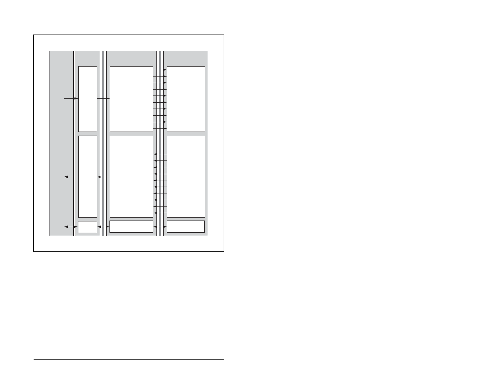
Figure 6.1 illustrates an example of an I/O image with 16-bit words.
Controller
EtherNet/IP
Scanner
Output
Image
(Write)
Input
Image
(Read)
Message
Handler
Module
Word and I/O
0 Logic Command
1 Reference
2 Datalink In A1
3 Datalink In A2
4 Datalink In B1
5 Datalink In B2
6 Datalink In C1
7 Datalink In C2
8 Datalink In D1
9 Datalink In D2
0 Pad Word
1 Pad Word
(1)
(1)
2 Logic Status
3 Feedback
4 Datalink Out A1
5 Datalink Out A2
6 Datalink Out B1
7 Datalink Out B2
8 Datalink Out C1
9 Datalink Out C2
10 Datalink Out D1
11 Datalink Out D2
Message
Buffer
DPI
Reliance Electric
Drive
Logic Command
Reference
Data In A1
Data In A2
Data In B1
Data In B2
Data In C1
Data In C2
Data In D1
Data In D2
Logic Status
Feedback
Data Out A1
Data Out A2
Data Out B1
Data Out B2
Data Out C1
Data Out C2
Data Out D1
Data Out D2
Message
Handler
1
Required by ControlLogix. May or may not be required by other controllers.
Figure 6.1 – ControlLogix I/O Image with All I/O Enabled (Example 1)
In figure 6.1, the configuration illustrates using 10 words of output
and 12 words of input (the module adds two pad words at the
beginning of the input). Depending on your application needs, this
may vary.
Using I/O Messaging
6-3
Page 62

For example, an image that uses 32-bit words for Reference and
four Datalinks would change the I/O image in figure 6.1 as follows:
Word Output I/O Word Input I/O
0 Logic Command/Status 0 - 1 Pad Word
1 Pad Word 2 Logic Command/Status
2 - 3 Reference/Feedback 3 Pad Word
4 - 7 Datalink A1/A2 4 - 5 Reference/Feedback
8 - 11 Datalink B1/B2 6 - 9 Datalink A1/A2
12 - 15 Datalink C1/C2 11 - 13 Datalink B1/B2
16 - 19 Datalink D1/D2 14 - 17 Datalink C1/C2
18 - 21 Datalink D1/D2
An image that uses a 16-bit Reference and 32-bit Datalinks would
change the I/O image in figure 6.1 as follows:
Word Output I/O Word Input I/O
0 Logic Command/Status 0 - 1 Pad Word
1 Pad Word 2 Logic Command/Status
2 Reference/Feedback 3 Pad Word
3 Pad Word 4 - 5 Reference/Feedback
4 - 7 Datalink A1/A2 6 - 9 Datalink A1/A2
8 - 11 Datalink B1/B2 11 - 13 Datalink B1/B2
12 - 15 Datalink C1/C2 14 - 17 Datalink C1/C2
16 - 19 Datalink D1/D2 18 - 21 Datalink D1/D2
As another example, figure 6.2 illustrates an I/O image that does
not use all of the I/O data. Only the Logic Command/Reference and
Datalink B are enabled. In this example, the reference is a 32-bit
word, and Datalinks are 16-bit words.
6-4
EtherNet/IP Communications Module
Page 63

EtherNet/IP
Controller
1
Required by ControlLogix. May or may not be required by other controllers.
2
LSW is Least Significant Word (Bits 15 -0). MSW is Most Significant Word (Bits 31 - 16).
Scanner
Output
Image
(Write)
Input
Image
(Read)
Message
Handler
Module Word and I/O
0 Logic Command
1 Pad Word
2 Reference (LSW)
3 Reference (MSW)
4 Datalink In B1
5 Datalink In B2
0 Pad Word
1 Pad Word
2 Logic Status
3 Pad Word
4 Feedback (LSW)
5 Feedback (MSW)
6 Datalink Out B1
7 Datalink Out B2
(1)
(1)
Message
Buffer
DPI
Reliance Electric
Drive
Logic Command
(2)
(2)
Reference
Data In A1
Data In A2
Data In B1
Data In B2
Data In C1
Data In C2
Data In D1
Data In D2
Logic Status
Feedback
Data Out A1
Data Out A2
Data Out B1
Data Out B2
Data Out C1
Data Out C2
Data Out D1
Data Out D2
Message
Handler
Figure 6.2 – ControlLogix I/O Image (Example 2)
6.3 Using Logic Command/Status
When enabled, the Logic Command/Status word is always word 0
in the output image and word 2 in the input image. The Logic
Command is a 16-bit word of control produced by the scanner and
consumed by the module. The Logic Status is a 16-bit word of
status produced by the module and consumed by the scanner.
This manual contains the bit definitions for compatible products
available at the time of publication in Appendix D, Logic Command/
Status Words. For other products, refer to their documentation.
Using I/O Messaging
6-5
Page 64

6.4 Using Reference/Feedback
When enabled, Reference/Feedback begins at word 1 (16-bit) or
word 2 (32-bit) in the I/O image. The
produced by the controller and consumed by the adapter. The
feedback
(16 bits or 32 bits) is produced by the adapter and
consumed by the controller. The size of the Reference/Feedback is
determined by the drive and displayed in Ref/Fdbk Size (18) in the
adapter.
Size Valid Values In I/O Image
16-bit -32768 to 32767 Word 1
32-bit -2147483648 to 2147483647 Word 2 and Word
The Reference value is a scaled value; it is not an engineering
value. For example, in Reliance Electric drives, the Reference is
scaled based on the value of Maximum Freq (55) where “32,767”
equals the Maximum frequency value, and “0” equals 0 Hz. Note
that the commanded maximum speed can never exceed the value
of Maximum Speed (82). The below table shows example
references and their results on a drive that has its Maximum Freq
(55) set to 130 Hz and Maximum Speed (82) set to 60 Hz.
Reference
Scale
Val ue
1
32767
100% 130 Hz
16384 50% 65 Hz
8192 25% 32.5 Hz 32.5 Hz 8192
0 0% 0 Hz 0 Hz 0
1. A value of 32767 is equivalent to the Parameter 55 frequency value. The effects of values
greater than 32767 depend on whether the DPI product uses a bipolar or unipolar
direction mode. Refer to the documentation for your DPI product.
2. The drive runs at 60 Hz instead of 130 Hz or 65 Hz because Parameter 82 - [Maximum
Speed] sets 60 Hz as the maximum speed.
3. The Feedback value is also scaled based on the value of Parameter 55 - [Maximum
Freq], For example, 60/130 = 0.46 so 32767 x 0.46 = 15123.
reference
Output
Speed
60 Hz
60 Hz
(16 bits or 32 bits) is
3
Feedback
Val uePercent Value
2
2
15123
15123
3
3
6-6
For Reference/Feedback details about other DPI Hosts, refer to
their respective User Manuals.
EtherNet/IP Communications Module
Page 65

6.5 Using Datalinks
A Datalink is a mechanism used by Reliance Electric drives to
transfer data to and from the controller. Datalinks allow a parameter
value to be changed without using an Explicit Message. When
enabled, each Datalink consumes either two 16-bit or 32-bit words
in both the input and output image depending on its size. The size
of Datalinks (16-bit words or 32-bit words) is determined by the
drive and displayed in Datalink Size (19) in the module.
Rules for Using Datalinks
• Each set of Datalink parameters in a Reliance Electric drive can
be used by only one module. If more than one module is
connected to a single drive, multiple modules must not try to use
the same Datalink.
• Parameter settings in the drive determine the data passed
through the Datalink mechanism. Refer to the documentation for
your drive.
• When you use a Datalink to change a value, the value is not
written to the Non-Volatile Storage (NVS). The value is stored in
volatile memory and lost when the drive loses power. Thus, use
Datalinks when you need to change a value of a parameter
frequently.
Using I/O Messaging
6-7
Page 66

6.5.1 32-Bit Parameters using 16-Bit Datalinks
To read (and/or write) a 32-bit parameter using 16-bit Datalinks,
typically both Datalinks of a pair (x1 and x2) are set to the same 32bit parameter.
For example, to read Elapsed MWh (9) in an SP600 drive, both
Datalink A1 and A2 are set to “9.” Datalink A1 will contain the least
significant word (LSW) and Datalink A2 the most significant word
(MSW). In this example, the parameter 9 value of 5.8 MWh is read
as a “58” in Datalink A1.
Most/Least Significant
Datalink
A1 LSW 9 58
A2 MSW 9 0
Regardless of the Datalink combination, x1 will always contain the
LSW and x2 will always contain the MSW. In the following examples
Power Up Marker (242) contains a value of 88.4541 hours.
Word Parameter Data (decimal)
Datalink
A1 LSW 242 32573
A2 - Not Used - 0 0
Datalink
A1 - Not Used - 0 0
A2 MSW 242 13
Datalink
A2 MSW 242 13
B1 LSW 242 32573
Most/Least Significant
Word Parameter Data (decimal)
Most/Least Significant
Word Parameter Data (decimal)
Most/Least Significant
Word Parameter Data (decimal)
32-bit data is stored in binary as follows:
MSW
LSW
31
through 2
2
15
through 2
2
16
0
Example:
Power Up Marker (242) = 88.4541 hours
MSW = 13
decimal
= 1101
= 219 + 218 + 216 = 851968
binary
LSW = 32573
851968 + 32573 = 884541
6-8
EtherNet/IP Communications Module
Page 67

6.6 Sample Ladder Logic Program
The sample ladder logic program works with a ControlLogix
controller and an SP600 drive.
6.6.1 Function of the Sample Program
With this program, you can perform the following actions:
• Obtain Logic Status information from the drive.
• Use the Logic Command to control the drive (for example, start).
• Send a Reference to the drive and receive Feedback from the
drive.
• Transmit Datalink data to and from the drive.
Table 6.1 – Parameter Settings for the Sample Program
Device Parameter Name Value Description
90 Speed Ref A Sel 22 ‘DPI Port 5’ (RECOMM-ENET)
300 Data In A1 140 Points to Par. 140 -(Accel Time 1)
301 Data In A2 142 Points to Par. 142 - (Decel Time 1)
302 Data In B1 100 Points to Par. 100 - (Jog Speed)
303 Data In B2 155 Points to Par. 155 - (Stop Mode A)
SP600 Drive
RECOMMENET Module
304 Data In C1 101 Points to Par. 101 - (Preset Speed 1)
305 Data In C2 102 Points to Par. 102 - (Preset Speed 2)
306 Data In D1 103 Points to Par. 103 - (Preset Speed 3)
307 Data In D2 104 Points to Par. 104 - (Preset Speed 4)
310 Data Out A1 140 Points to Par. 140 - (Accel Time 1)
311 Data Out A2 142 Points to Par. 142 - (Decel Time 1)
312 Data Out B1 100 Points to Par. 100 - (Jog Speed)
313 Data Out B2 155 Points to Par. 155 - (Stop Mode A)
314 Data Out C1 101 Points to Par. 101 - (Preset Speed 1)
315 Data Out C2 102 Points to Par. 102 - (Preset Speed 2)
316 Data Out D1 103 Points to Par. 103 - (Preset Speed 3)
317 Data Out D2 104 Points to Par. 104 - (Preset Speed 4)
04 – 07 IP Addr Cfg 1 – 4 131.200
.130.178
23 DPI I/O Cfg xxx1 1111 Enables Cmd/Ref, Datalinks A-D
35 M-S Input xxx1 1111 Configures the I/O Data to be
36 M-S Output xxx1 1111 Configures the I/O Data to be
IP Address for the module
transferred from the controller on the
network to the drive.
transferred from the drive to the
controller on the network.
Using I/O Messaging
6-9
Page 68

6.7 RSLogix 5000 Configuration
Controller Tags
When you add the module and drive to the I/O configuration (refer to
chapter 5), RSLogix 5000 software automatically creates controller
tags for them. In this example program, the following controller tags
are used.
SP600:C
SP600:I
SP600:O
Figure 6.3 – Controller Tags for the Sample ControlLogix Ladder Logic
Program
You can expand the Output and Input tags to reveal the output and
input configuration. The Output tag for this sample program requires
ten 16-bit words of data (see figure 6.4). The Input tag for this
example requires twelve 16-bit words of data (see figure 6.5).
SP600:C
SP600:I
SP600:O
SP600:O.Data
SP600:O.Data[0]
SP600:O.Data[1]
SP600:O.Data[2]
SP600:O.Data[3]
SP600:O.Data[4]
SP600:O.Data[5]
SP600:O.Data[6]
SP600:O.Data[7]
SP600:O.Data[8]
SP600:O.Data[9]
Figure 6.4 – Output Image for the Sample ControlLogix Ladder Logic
Program
SP600 Output Image Ta...
SP600 Logic Command
SP600 Reference
SP600 Datalink A1 In
SP600 Datalink A2 In
SP600 Datalink B1 In
SP600 Datalink B2 In
SP600 Datalink C1 In
SP600 Datalink C2 In
SP600 Datalink D1 In
SP600 Datalink D2 In
6-10
EtherNet/IP Communications Module
Page 69

SP600:C
SP600:I
SP600:I.Data
SP600:I.Data[0]
SP600:I.Data[1]
SP600:I.Data[2]
SP600:I.Data[3]
SP600:I.Data[4]
SP600:I.Data[5]
SP600:I.Data[6]
SP600:I.Data[7]
SP600:I.Data[8]
SP600:I.Data[9]
SP600:I.Data[10]
SP600:I.Data[11]
SP600 Input Image Table
System Overhead
System Overhead
SP600 Logic Status
SP600 Feedback
SP600 Datalink A1 Out
SP600 Datalink A2 Out
SP600 Datalink B1 Out
SP600 Datalink B2 Out
SP600 Datalink C1 Out
SP600 Datalink C2 Out
SP600 Datalink D1 Out
SP600 Datalink D2 Out
Figure 6.5 – Input Image for the Sample ControlLogix Ladder Logic Program
Program Tags
In addition to the Controller tags that are automatically created, you
need to create the Program tags shown in figure 6.6 for this sample
program.
SP600 Speed Feedback
SP600 Speed Reference
Figure 6.6 – Program Tags for Sample ControlLogix Ladder Logic Program
6.8 Logic Command/Status Words
This example uses the Logic Command word and Logic Status
word for SP600 drives. Refer to Appendix D, Logic Command/
Status Words, to view these. The definition of the bits in these
words may vary if you are using a different DPI product. Refer to the
documentation for your product.
Using I/O Messaging
6-11
Page 70

6.9 Sample ControlLogix Ladder Logic
Program
S600
Logic Status
Word
bit 01 (ACTIVE)
SP600:I.Data[2].1
0
SP600
Logic Status
Word
bit 07 (FAULT)
SP600:I.Data[2].7
1
2
DriveCommandStop
3
DriveCommandStart
4
DriveCommandJog
5
DriveCommandClearFault
6
Transfer Speed Reference data to the SP600 drive.
7
Copy File
Source SP600:I.Data[3]
Dest DriveFeedback
Length 1
Copy File
Source DriveReference
Dest SP600:O.Data[1]
Length 1
DriveStatusRunning
DriveStatusFaulted
SP600
Speed Feedback
COP
SP600
Logic Command
bit 00 (STOP)
SP600:O.Data[0].0
SP600
Logic Command
bit 01 (START)
SP600:O.Data[0].1
SP600
Logic Command
bit 02 (JOG)
SP600:O.Data[0].2
SP600
Logic Command
bit 03
(CLEAR FAULTS)
SP600:O.Data[0].3
SP600
Reference
COP
Read Datalink A-D data from the SP600 drive (Data Out A1 - Data Out D2).
8
Copy File
Source SP600:I.Data[4]
Dest
Length 8
SP600
Datalink A1 Out
COP
DatalinkDataFromDrive[0]
Figure 6.7 – Sample ControlLogix Ladder Logic Program for I/O Messaging
6-12
EtherNet/IP Communications Module
Page 71

Write Datalink A-D data to the SP600 drive (Data In A1 - Data In D2).
9
(End)
Copy File
Source DatalinkDataToDrive[0]
Dest SP600:O.Data[2]
Length 8
SP600
Datalink A1 In
COP
Figure 6.8 – Sample ControlLogix Ladder Logic Program for I/O Messaging
(Continued)
6.10 Sample Datalink Data
The following figure shows the Datalink data used in the sample
program.
SP600 Datalink A1 Out
SP600 Datalink A2 Out
SP600 Datalink B1 OutSP600 Datalink B1 Out
SP600 Datalink B2 Out
SP600 Datalink C1 Out
SP600 Datalink C2 Out
SP600 Datalink D1 Out
SP600 Datalink D2 Out
SP600 Datalink A1 In
SP600 Datalink A2 In
SP600 Datalink B1 In
SP600 Datalink B2 In
SP600 Datalink C1 In
SP600 Datalink C2 In
SP600 Datalink D1 In
SP600 Datalink D2 In
Figure 6.9 – Sample Datalink Data for the Sample Ladder Logic Program
Using I/O Messaging
6-13
Page 72

6-14
EtherNet/IP Communications Module
Page 73

CHAPTER 7
Using Explicit Messaging
Chapter 7 provides information and examples that explain how to
use Explicit Messaging to configure and monitor a Reliance Electric
drive and an EtherNet/IP module.
ATTENTION: The examples in this publication are intended
solely for purposes of example. There are many variables and
!
requirements with any application. Rockwell Automation does
not assume responsibility or liability (to include intellectual
property liability) for actual use of the examples shown in this
publication. Failure to observe this precaution could result in
bodily injury and/or damage to equipment.
ATTENTION: If Explicit Messages are programmed to write
parameter data to Non-Volatile Storage (NVS) frequently, the
NVS will quickly exceed its life cycle and cause the drive to
malfunction. Do not create a program that frequently uses
Explicit Messages to write parameter data to NVS. Datalinks
do not write to NVS and should be used for frequently changed
parameters. Failure to observe this precaution could result in
bodily injury and/or damage to equipment.
Refer to chapter 6 for information about the I/O Image, using Logic
Command/Status, Reference/Feedback, and Datalinks.
7.1 About Explicit Messaging
Explicit Messaging is used to transfer data that does not require
continuous updates. With Explicit Messaging, you can configure
and monitor a slave device’s parameters on the EtherNet/IP
network.
Using Explicit Messaging
7-1
Page 74

7.2 Formatting Explicit Messages
Explicit Messages for the ControlLogix Controller
ControlLogix scanners and bridges accommodate both
downloading Explicit Message Requests and uploading Explicit
Message Responses. The scanner or bridge module can
accommodate one request or response for each transaction block.
Each transaction block must be formatted as shown in figure 7.1 .
➓
➊
➋
➌
➎
Box Description
Message Type
➊
The message type is usually CIP Generic.
Service Type
➋
The service type indicates the service (for example, Get Attribute
Single or Set Attribute Single) that you want to perform. Available
services depend on the class and instance that you are using. Refer
to Appendix C EtherNet/IP Objects.
Service Code
➌
The service code is the code for the requested EtherNet/IP service.
This value changes based on the Service Type that has been
selected. In most cases, this is a read-only box.
If you select “Custom” in the Service Type box, then you need to
specify a service code in this box (for example, 4B for a Get Attributes
Scattered service or 4C for a Set Attributes Scattered service).
Figure 7.1 – ControlLogix Message Format in RSLogix 5000
➍
➏
➐
➑
➒
7-2
EtherNet/IP Communications Module
Page 75

Box Description
Class
➍
The class is an EtherNet/IP class. Refer to Appendix C, EtherNet/IP
Objects, for available classes.
Instance
➎
The instance is an instance (or object) of an EtherNet/IP class. Refer
to Appendix C, EtherNet/IP Objects, for available instances for each
class.
Attribute
➏
The attribute is a class or instance attribute. Refer to Appendix C,
Ethernet/IP Objects, for available attributes for each class or
instance.
Source Element
➐
This box contains the name of the tag for any service data to be sent
from the scanner or bridge to the module and drive.
Source Length
➑
This box contains the number of bytes of service data to be sent in
the message.
Destination
➒
This box contains the name of the tag that will receive service
response data from the module and drive.
Path
➓
The path is the route that the message will follow.
Note: Click Browse to find the path or type in the name of a module
that you previously mapped.
Name
The name for the message.
Figure 7.1 – ControlLogix Message Format in RSLogix 5000 (Continued)
Note: To display the Message Configuration dialog box in
RSLogix 5000, add a message instruction (MSG), create a new tag
for the message (properties: Base tag type, MESSAGE data type,
controller scope), and click the Configure button.
7.3 Performing Explicit Messages
There are five basic events in the Explicit Messaging process
defined below. The details of each step will vary depending on the
controller. Refer to the documentation for your controller.
Important: There must be a request message and a response
message for all Explicit Messages, whether you are
reading or writing data.
Using Explicit Messaging
7-3
Page 76

➎
Complete Explicit
Message
➍
Retrieve Explicit
Message Response
➊
Set up and send
Explicit Message
➋
➌
➊
➋
➌
➍
➎
Note: The scanner module may be integrated with the controller (for
example, ControlLogix).
Format the required data and set up the ladder
logic program to send an Explicit Message
request to the scanner or bridge module
(download).
The scanner or bridge module transmits the
Explicit Message Request to the slave device
over the EtherNet/IP network.
The slave device transmits the Explicit Message
Response back to the master.
The controller retrieves the Explicit Message
Response. It may be required to repeat steps 13, depending on the amount of data.
The Explicit Message is complete.
Figure 7.2 – Explicit Message Process
7-4
EtherNet/IP Communications Module
Page 77

7.4 About the Explicit Message Examples
These examples show how to format and execute the following
types of Explicit Messages using a ControlLogix controller:
• Get Attribute Single
• Set Attribute Single
Message Formats
When formatting a message example, refer to Formatting Explicit
Messages in this chapter for an explanation of the content of each
box.
Also, to format and execute these message examples, you need the
Controller tags displayed in figure 7.3.
SP600:C
SP600:I
SP600:O
Figure 7.3 – Controller Tags for Explicit Messages
• Get Attributes Scattered
• Set Attributes Scattered
Ladder Logic Rungs
The ladder logic rungs for the examples in this chapter can be
appended after rung 9 in the ladder logic program (figure 6.7) in
chapter 6, Using I/O Messaging.
Source and Destination Data
The values in the examples that appear in this chapter for the
source and destination data may vary in your application.
Using Explicit Messaging
7-5
Page 78

7.4.1 Get Attribute Single Message Example
A Get Attribute Single message reads a single attribute value. In
this example, we read the value of a parameter in an SP600 drive.
Message Format Example
SP600
7-6
Figure 7.4 – Message Format for a Get Attribute Single Message
Table 7.1 identifies key settings for the message format:
Table 7.1 – Settings for Message Format
Configuration Value Description Page
1
Service Type
Service Code
Class
Instance
Attribute
Destination
1. The default setting for Service Type is “Custom,” which enables you to
enter a Service Code that is not available from the Service Type pulldown
menu. When you select a Service Type other than “Custom” from the
pulldown menu, an appropriate Hex. value is automatically assigned to
the Service Code box which grays out (inaccessible).
Get Attribute Single
1
e (Hex.)
93 (Hex.)
1 (Dec.)
9 (Hex.)
GetAttributeSingleData
Read Parameter data
Code for Get_Attribute_Single
DPI Parameter Object
Parameter 1 (Output Freq)
Para me ter Value
Controller tag for response data
EtherNet/IP Communications Module
C-24
C-10
C-20
C-20
C-21
Page 79

Ladder Logic Rung Example
Get Attribute Single Message Example
Get Attribute Single
PerformGetAttributeSingle
10
Type - CIP Generic
Message Control
Service
MSG
GetAttributeSingle
...
EN
DN
ER
Figure 7.5 – Get Attribute Single Message Example
Destination Data Example
In this example, the Get Attribute Single message reads Output
Freq (1) in the drive and returns its value to the destination tag
named GetAttributeSingleData.
Figure 7.6 – Example of Destination Data from a Get Attribute Single
Message
The output frequency is 32.5 Hz.
Using Explicit Messaging
7-7
Page 80

7.4.2 Set Attribute Single Message Example
A Set Attribute Single message writes a value for a single attribute.
In this example, we write the value of a parameter in an SP600
drive.
Message Format Example
SP600
7-8
Figure 7.7 – Message Format for a Set Attribute Single Message
Table 7.2 identifies key settings for the data format:
Table 7.2 – Key Settings for Data Format
Configuration Value Description Page
Service Type
Service Code
Class
Instance
Attribute
Source Element
Source Length
1. The default setting for Service Type is “Custom,” which enables you to
enter a Service Code that is not available from the Service Type pulldown
menu. When you select a Service Type other than “Custom” from the
pulldown menu, an appropriate Hex. value is automatically assigned to
the Service Code box which grays out (inaccessible).
1
Set Attribute Single
1
10 (Hex.)
93 (Hex.)
107 (Dec.)
9 (Hex.)
SetAttributeSingleData
2 bytes
Write parameter data
Code for Set_Attribute_Single
DPI Parameter Object
Parameter 107 (Preset Speed 7)
Parameter Value
Controller tag for write data
One 16-bit word of data is sent
C-24
C-10
C-20
C-20
C-21
EtherNet/IP Communications Module
Page 81
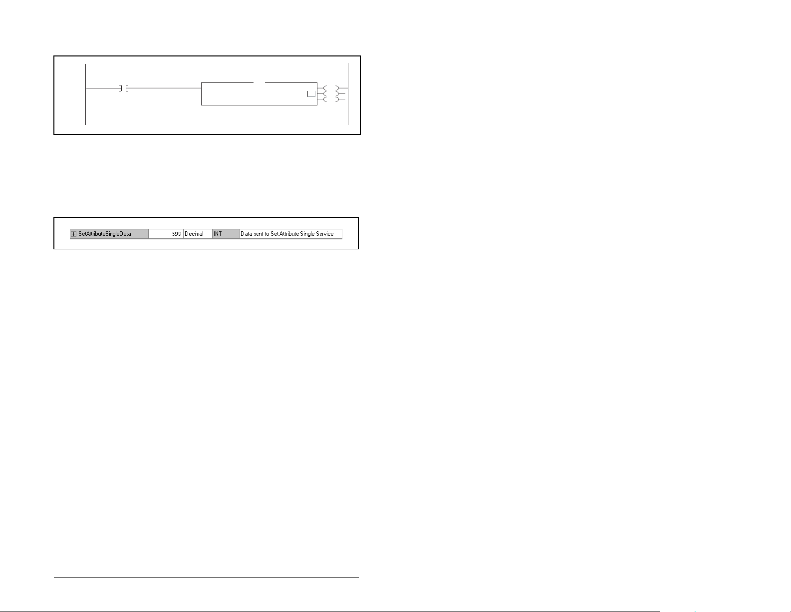
Ladder Logic Rung Example
Set Attribute Single
PerformSetAttributeSingle
11
Type - CIP Generic
Message Control
Service
MSG
SetAttributeSingle
...
Figure 7.8 – Set Attribute Single Message Example
Example Source Data
In this example, the Set Attribute Single message writes 599, the
value in the source tag named SetAttributeSingleData, to Preset
Speed 7 (107) in the drive.
Figure 7.9 – Example of Source Data from Set Attribute Single Message
59.9 Hz is written to the parameter.
EN
DN
ER
Using Explicit Messaging
7-9
Page 82

7.4.3 Get Attributes Scattered Message Example
A Get Attributes Scattered message reads the values of multiple
attributes. In this example, we read the values of various
parameters in an SP600 drive.
Message Format Example
SP600
7-10
Figure 7.10 – Message Format for a Get Attributes Scattered Message
The following table identifies key settings for the message format:
Table 7.3 – Key Settings for Message Format
Configuration Value Description Page
Service Type
Service Code
Class
Instance
Attribute
Source
Element
Source Length
Destination
1. The default setting for Service Type is “Custom,” which enables you to
enter a Service Code that is not available from the Service Type pulldown
menu. When you select a Service Type other than “Custom” from the
pulldown menu, an appropriate Hex. value is automatically assigned to
the Service Code box which grays out (inaccessible).
1
Custom
1
4B
93 (Hex.)
0 (Dec.)
0 (Hex.)
GetScatteredRequestData
30 Bytes
GetScatteredResponseData
Required for scattered messages
Code for Get Attributes Scattered
DPI Parameter Object
Required for scattered messages
Required for scattered messages
Controller tag for request data
Fifteen 16-bit words of data
Controller tag for response data
C-24
C-20
7-12
7-12
7-13
EtherNet/IP Communications Module
Page 83

Ladder Logic Rung Example
Get Attributes
PerformGetAttributesScattered
12
Type - CIP Generic
Message Control
Scattered Service
MSG
GetAttributesScattered
Figure 7.11 – Example of Get Attributes Scattered Message
Explanation of Source and Destination Data
The data structures in figure 7.13 uses 16-bit words and can get up
to twenty-two parameters in a single message. In the Response
Message, a parameter number with the high bit set indicates that
the associated parameter value field contains an error code.
Request (Source Data) Response (Destination Data)
Word 0 Parameter Number Word 0 Parameter Number
1 Pad Word 1 Parameter Value LSW
2 Pad Word 2 Parameter Value MSW
3 Parameter Number 3 Parameter Number
4 Pad Word 4 Parameter Value LSW
5 Pad Word 5 Parameter Value MSW
6 Parameter Number 6 Parameter Number
7 Pad Word 7 Parameter Value LSW
8 Pad Word 8 Parameter Value MSW
9 Parameter Number 9 Parameter Number
10 Pad Word 10 Parameter Value LSW
11 Pad Word 11 Parameter Value MSW
12 Parameter Number 12 Parameter Number
13 Pad Word 13 Parameter Value LSW
14 Pad Word 14 Parameter Value MSW
15 Parameter Number 15 Parameter Number
16 Pad Word 16 Parameter Value LSW
17 Pad Word 17 Parameter Value MSW
...
63 Parameter Number 63 Parameter Number
64 Pad Word 64 Parameter Value LSW
65 Pad Word 65 Parameter Value MSW
...
...
EN
DN
ER
Figure 7.12 – Data Structure for Get Scattered Attributes Messages
Using Explicit Messaging
7-11
Page 84

Source Data Example
In this example, we use the data structure in figure 7.13 in the
source tag named GetScatteredRequestData to read the following
five parameters:
• Output Freq (1)
• Output Current (3)
• Output Voltage (6)
• DC Bus Voltage (12)
• Analog In1 Value (17)
7-12
Figure 7.13 – Source Data Example
EtherNet/IP Communications Module
Page 85

Destination Data Example
The Get Attributes Scattered message reads the multiple
parameters and returns their values to the destination tag
(GetScatteredResponseData).
Figure 7.14 – Destination Data Example
In this example, the parameters have the following values:
Drive Parameter Value
Output Freq (1) 32.5 Hz
Output Current (3) 0.1 Amp
Output Voltage (6) 118.7 VAC
DC Bus Voltage (12) 329.2 VDC
Analog In2 Value (17) 8.318 mA
Using Explicit Messaging
7-13
Page 86

7.4.4 Set Attributes Scattered Message Example
A Set Attributes Scattered message writes values to multiple
attributes. In this example, we write the values of various
parameters in an SP600 drive.
Example Message Format
SP600
7-14
Figure 7.15 – Message Format for a Set Attributes Scattered Message
The following table identifies key settings for the message format:
Table 7.4 – Message Format Settings
Configuration Value Description Page
Service Type
Service Code
Class
Instance
Attribute
Source
Element
Source Length
Destination
1. The default setting for Service Type is “Custom,” which enables you to
enter a Service Code that is not available from the Service Type pulldown
menu. When you select a Service Type other than “Custom” from the
pulldown menu, an appropriate Hex. value is automatically assigned to
the Service Code box which grays out (inaccessible).
1
Custom
1
4C
93 (Hex.)
0 (Dec.)
0 (Hex.)
SetScatteredRequestData
30 Bytes
SetScatteredResponseData
Required for scattered messages
Code for Get Attributes Scattered
DPI Parameter Object
Required for scattered messages
Required for scattered messages
Controller tag for request data
Fifteen 16-bit words of data
Controller tag for response data
C-24
C-20
7-16
7-16
7-17
EtherNet/IP Communications Module
Page 87

Ladder Logic Rung Example
Set Attributes
PerformSetAttributesScattered
13
Type - CIP Generic
Message Control
Scattered Service
MSG
SetAttributesScattered
...
Figure 7.16 – Set Attributes Scattered Message Example
Explanation of Source and Destination Data
The data structures in figure 7.17 use 16-bit words and can set up
to twenty-two parameters in a single message. In the Response
Message, a parameter number with the high bit set indicates that
the associated pad word field contains an error code.
Request (Source Data) Response (Destination Data)
Word 0 Parameter Number Word 0 Parameter Number
1 Parameter Value LSW 1 Pad Word or Error Code
2 Parameter Value MSW 2 Pad Word
3 Parameter Number 3 Parameter Number
4 Parameter Value LSW 4 Pad Word or Error Code
5 Parameter Value MSW 5 Pad Word
6 Parameter Number 6 Parameter Number
7 Parameter Value LSW 7 Pad Word or Error Code
8 Parameter Value MSW 8 Pad Word
9 Parameter Number 9 Parameter Number
10 Parameter Value LSW 10 Pad Word or Error Code
11 Parameter Value MSW 11 Pad Word
12 Parameter Number 12 Parameter Number
13 Parameter Value LSW 13 Pad Word or Error Code
14 Parameter Value MSW 14 Pad Word
15 Parameter Number 15 Parameter Number
16 Parameter Value LSW 16 Pad Word or Error Code
17 Parameter Value MSW 17 Pad Word
...
63 Parameter Number 63 Parameter Number
64 Parameter Value LSW 64 Pad Word
65 Parameter Value MSW 65 Pad Word
...
EN
DN
ER
Figure 7.17 – Data Structures for Set Attributes Scattered Message
Using Explicit Messaging
7-15
Page 88

Source Data Example
In this example, we use the data structure in figure 7.18 in the
source tag (SetScatteredRequestData) to write new values for
these parameters:
Drive Parameter Value
Accel Time 2 (141) 11.1 sec
Decel Time 2 (143) 22.2 sec
Preset Speed 5 (105) 33.3 Hz
Preset Speed 6 (106) 44.4 Hz
Preset Speed 7 (107) 55.5 Hz
7-16
Figure 7.18 – Source Data Example
EtherNet/IP Communications Module
Page 89

Example Destination Data
The results of the message appear in the destination tag named
SetScatteredResponseData. Values of “0” indicate no errors
occurred.
Figure 7.19 – Destination Data Example
Using Explicit Messaging
7-17
Page 90

7-18
EtherNet/IP Communications Module
Page 91

CHAPTER 8
Troubleshooting the
Module and Network
Chapter 8 contains information for troubleshooting the EtherNet/IP
module and the network.
8.1 Understanding the Status Indicators
The module has four status indicators. They can be viewed on the
module or through the drive cover.
➊
➋
➌
➍
Status
Number
➊ DRIVE DPI Connection Status Section 8.1.1
➋ MS Module Status Section 8.1.2
➌ NET A EtherNet/IP
➍ NET B EtherNet/IP Transmit
Indicator Description Refer to...
Table 8.1 – Status Indicators (Location on Drive May Vary)
➊
➋
➌
➍
Section 8.1.3
Connection Status
Section 8.1.4
Status
Troubleshooting the Module and Network
8-1
Page 92

8.1.1 DRIVE Status Indicator
Table 8.2 – DRIVE Status Indicator: State Definitions
Status Cause Corrective Action
Off The module is not
Flashing
Red
Solid
Red
Orange The module is
Flashing
Green
Solid
Green
powered or is not
connected properly to
the drive.
The module is not
receiving a ping
message from the
drive.
The drive has refused
an I/O connection from
the module.
Another DPI peripheral
is using the same DPI
port as the module.
connected to a product
that does not support
Reliance Electric DPI
communications.
The module is
establishing an I/O
connection to the drive.
The module is properly
connected and is
communicating with the
drive.
• Securely connect the module
to the drive using the ribbon
cable.
• Apply power to the drive.
• Verify that cables are
securely connected.
• Cycle power to the drive.
Important: Cycle power to the
product after making any of the
following corrections:
• Verify that all DPI cables are
securely connected and not
damaged. Replace cables if
necessary.
• Verify that the DPI Host
supports Datalinks.
• Configure the module and
DPI Host to use a Datalink
that is not already being
used by another peripheral.
• Connect the module to a
product that supports
Reliance Electric DPI
communications (for
example, SP600, LiquiFlo
2.0 or GV6000 drives).
• No action. Normal behavior if
no DPI I/O is enabled.
• No action.
8-2
EtherNet/IP Communications Module
Page 93

8.1.2 MS Status Indicator
Table 8.3 – MS Status Indicator: State Definitions
Status Cause Corrective Action
Off The module is not
Flashing
Red
Solid
Red
Flashing
Green
Solid
Green
powered.
The module has
failed the firmware
test.
The module is being
flash upgraded.
The module has
failed the hardware
test.
The module is
operational but is not
transferring I/O data.
The module is
operational and
transferring I/O data.
• Securely connect the module
to the drive using the Internal
Interface cable.
• Apply power to the drive and
network.
• Clear faults in the module.
• Cycle power to the drive.
• If cycling power does not
correct the problem, the
parameter settings may have
been corrupted. Reset defaults
and reconfigure the module.
• If resetting defaults does not
correct the problem, flash the
module with the latest firmware
release.
• Cycle power to the drive.
• Replace the module.
• Place the scanner in RUN
mode.
• Program the controller to
recognize and transmit I/O to
the module.
• Configure the module for the
program in the controller.
• Normal behavior if no DPI I/O
is enabled.
• No action.
Troubleshooting the Module and Network
8-3
Page 94

8.1.3 NET A Status Indicator
Table 8.4 – NET A Status Indicator: State Definitions
Status Cause Corrective Action
Off The module and/or
Solid Red The module failed
Flashing
Red
Flashing
Red/
Green
Flashing
Green
Solid
Green
network is not
powered, the
module is not
connected properly
to the network, or
the module needs
an IP address.
duplicated IP
address detection
test.
An EtherNet/IP
connection has
timed out.
The module is
performing a self
test.
The module is
properly connected
but is not
communicating
with any devices
on the network.
The module is
properly connected
and
communicating
with the network.
• Securely connect the module to
the drive using the Internal
Interface cable and to the
network using an Ethernet
cable.
• Correctly connect the Ethernet
cable to the Ethernet connector.
• Set a unique IP address using a
BOOTP server or disabling
BOOTP and using parameters.
• Apply power to the drive and
network.
• Configure the module to use a
unique IP address and cycle
power.
• Place the scanner in RUN
mode, or apply power to the
peer device that will send I/O.
• Check the amount of traffic on
the network.
• No action is required.
• Place the controller in RUN, or
apply power to the peer device
that will send I/O.
• Program a controller or peer
device to recognize and
transmit I/O or make a
messaging connection to the
module.
• Configure the module for the
program in the controller or the
I/O from the peer device.
• No action required.
8-4
EtherNet/IP Communications Module
Page 95

8.1.4 NET B Status Indicator
Table 8.5 – NET B Status Indicator: State Definitions
Status Cause Corrective Action
Off The module is not
Flashing
Green
powered or is not
transmitting on the
EtherNet/IP
network.
The module is
transmitting on the
EtherNet/IP
network.
If Net A is off:
• Securely connect the module to
the drive using the Internal
Interface cable and to the
network using an Ethernet
cable.
• Correctly connect the Ethernet
cable to the Ethernet connector.
• Set a unique IP address using a
BOOTP server or by disabling
BOOTP and using parameters.
If Net A is solid Red:
• Configure the module to use a
unique IP address and cycle
power.
If Net A is flashing red/green or
red:
• Check the IP address in the
module and scanner.
• Ping the module.
Normal condition if the module is
idle.
• No action required.
Troubleshooting the Module and Network
8-5
Page 96

8.2 Module Diagnostic Items
Table 8.6 lists diagnostic items that can be accessed using
VS Utilities software or the LCD OIM. Diagnostic items can help you
or Rockwell Automation personnel troubleshoot communication
problems.
Table 8.6 – Module Diagnostic Items
No. Event Description
1 Common Logic
Cmd
2 Prod Logic Cmd The current value of the Product-Specific Logic
3 Reference The current value of the Product-Specific
4 Common Logic Sts The current value of the Common Logic Status
5 Prod Logic Sts The current value of the Product-Specific Status
6 Feedback The current value of the Product-Specific
7
Datalink A1 In
8
Datalink A2 In
9
Datalink B1 In
10
Datalink B2 In
11
Datalink C1 In
12
Datalink C2 In
13
Datalink D1 In
14
Datalink D2 In
15
Datalink A1 Out
16
Datalink A2 Out
17
Datalink B1 Out
18
Datalink B2 Out
19
Datalink C1 Out
20
Datalink C2 Out
21
Datalink D1 Out
22
Datalink D2 Out
23 DPI Rx Errors The current value of the DPI Receive error
24 DPI Rx Err Max The maximum value (since reset) of the DPI
25 DPI Tx Errors The current value of the DPI Transmit error
26 DPI Tx Err Max The maximum value (since reset) of the DPI
The current value of the Common Logic
Command being transmitted to the host.
Command being transmitted to the host.
Reference being transmitted to the host.
being received from the host.
being received from the host.
Feedback being received from the host.
The current value of the specified Datalink being
transmitted to the host. (Value of 0 if datalink is
not used).
The current value of the specified Datalink being
received from the host.
counter.
Receive error counter.
counter.
Transmit error counter.
8-6
EtherNet/IP Communications Module
Page 97

Table 8.6 – Module Diagnostic Items (Continued)
No. Event Description
27 Boot Flash Count The number of times the Boot flash segment has
been updated.
28 App Flash Count The number of times the Application flash
segment has been updated in the field.
29 M-S Input Size The size of data transferred from the network to
the drive.
30 M-S Output Size The size of data transferred from the drive to the
network.
31
HW Addr 1
32
HW Addr 2
33
HW Addr 3
34
HW Addr 4
35
HW Addr 5
36
HW Addr 6
37
IP Addr Act 1
38
IP Addr Act 2
39
IP Addr Act 3
40
IP Addr Act 4
The decimal value of each byte in the module’s
Ethernet hardware address.
255 : 255 : 255 : 255 : 255 : 255
[HW Addr 1]
[HW Addr 2]
[HW Addr 3]
[HW Addr 4]
HW Addr 5]
[HW Addr 6]
The value of each byte in the module’s current IP
address. A value of “0” appears if the module
does not currently have an IP address.
255 . 255 . 255 . 255
[IP Addr Act 1]
[IP Addr Act 2]
[IP Addr Act 3]
41
Subnet Act 1
42
Subnet Act 2
43
Subnet Act 3
44
Subnet Act 4
Troubleshooting the Module and Network
The value of each byte in the module’s current
subnet mask. A value of “0” appears if the module
does not currently have a subnet mask.
[Subnet Act 1]
[Subnet Act 2]
[IP Addr Act 4]
255 . 255 . 255 . 255
[Subnet Act 3]
[Subnet Act 4]
8-7
Page 98

Table 8.6 – Module Diagnostic Items (Continued)
No. Event Description
45
Gateway Act 1
46
Gateway Act 2
47
Gateway Act 3
48
Gateway Act 4
The value of each byte in the module’s current
gateway address. A value of “0” appears if the
module does not currently have a gateway
address.
255 . 255 . 255 . 255
[Gateway Act 1]
[Gateway Act 2]
[Gateway Act 3]
[Gateway Act 4]
49 EN Rx Overruns The number of receive buffer overruns reported
by the Ethernet hardware.
50 EN Rx Packets The number of Ethernet packets that the module
has received.
51 EN Rx Errors The number of receive errors reported by the
Ethernet hardware.
52 EN Tx Packets The number of Ethernet packets that the module
has sent.
53 EN Tx Errors The number of transmit errors reported by the
Ethernet hardware.
54 Last TCP Reset Last reason that the module reset or rejected a
TCP/IP connection.
55 Missed IO Pkts Number of incoming I/O connection packets that
the module did not receive.
56 OPT Status Operating status of optional I/O board (in External
Comms Kit).
57 OPT RX Errors Number of optional I/O board receive errors.
58 OPT FW Version Firmware version of optional I/O board (in
External Comms Kit).
8-8
EtherNet/IP Communications Module
Page 99

8.3 Viewing and Clearing Events
The module maintains an event queue that reports the history of its
actions. You can view the event queue using an LCD OIM or
VS Utilities software.
To View and Clear Events Using an LCD OIM
Use the procedure shown in figures 8.2 and 8.3 to access the event
queue using the LCD OIM. Note that you must have the RECOMMENET module as the selected device to access the event queue.
>>
Stopped Auto
P5: RECOM M-ENET
Main Menu
Diagnostics
Monitor
Highlight Diagnostics icon
Lang
Diagnostics:
View Event Queue
Device Version
OIM Version
Highlight item
Press F2 key to
clear event queue
1
EvtQ# : E#xxx xx
Online @ 500kbps
Clrqu
Figure 8.1 – Viewing and Clearing Events Using an LCD OIM on a SP600 or LiquiFlo
2.0 Drive
Parameters
P5 Diagnostics
Groups
Linear List
Changed Params
PARAM DIAGSTARTUP
Use the SEL key to select the DIAG tab and then the Up/Down arrow keys
to highlight "Events". Press the ENTER key and then the Up/Down arrow
keys to highlight "View Event Queue". Press the ENTER key to view the
list of events in the event queue. Use the UP/DOWN arrow keys to
highlight the event of interest and then the ENTER key to see details
about that event.
SEL
P5 Events
SEL
Events
Device Select
Device Name
Device Version
Device Items
PARAM DIAGSTARTUP
SEL
P5
View Event Queue
Clear Events
Clear Event Queue
View Event Queue
P5
E01:EN Link Up
E02:Control Enabled
E03:Type 0 Login
E04:Online @ 500kbps
E05:Normal Startup
Event Queue 1
P5
1 E# 37
EvtQ#
EN Link Up
Accum:
4:27:43.590
Figure 8.2 – Viewing and Clearing Events Using an LCD OIM on a GV6000 Drive
Troubleshooting the Module and Network
8-9
Page 100

Events
Many events in the event queue occur under normal operation.
However, if you encounter communication problems, the events can
help you or Rockwell Automation personnel troubleshoot the
problem. Table 8.7 lists events that may appear in the event queue.
Table 8.7 – Event Codes and Descriptions
Code Event Description
1 No Event Empty event queue entry.
2 DPI Bus Off Flt A bus-off condition was detected on DPI. This
event may be caused by loose or broken
cables or by noise.
3 Ping Time Flt A ping message was not received on DPI
within the specified time.
4 Port ID Flt The module is not connected to a correct port
5 Port Change Flt The DPI port changed.
6 Host Sent Reset The DPI product issued this because it was
7 EEPROM Sum Flt The EEPROM in the module is corrupt.
8 Online @ 125kbps The module and DPI product are
9 Online @ 500kbps The module and DPI product are
10 Bad Host Flt The module was connected to an incompatible
11 Dup. Port Flt Another peripheral with the same port number
12 Type 0 Login The module has logged in for type 0 control.
13 Type 0 Time Flt The module has not received a type 0 status
14 DL Login The module has logged into a Datalink.
15 DL Reject Flt The host rejected an attempt to log in to a
16 DL Time Flt The module has not received a Datalink
17 Reserved Not used.
18 Control Disabled The module has sent a “Soft Control Disable”
19 Control Enabled The module has sent a “Soft Control Enable”
20 Message Timeout A Client-Server message sent by the
on a DPI product.
reset.
communicating at 125 kbps.
communicating at 500 kbps.
product.
is already in use.
message within the specified time.
Datalink because the Datalink is not supported
or is used by another peripheral.
message within the specified time.
command to the DPI product.
command to the DPI product.
peripheral was not completed.
Troubleshooting the Module and Network
8-10
 Loading...