

Page 1

DeviceNet Adapter
for use with
DPI AC Drives
M/N RECOMM-DNET
Instruction Manual
D2-3478
Page 2
The information in this manual is subject to change without notice.
Trademarks not belonging to Rockwell Automation are
property of their respective companies.
Throughout this manual, the following notes are used to alert you to safety
considerations:
ATTENTION:
circumstances that can lead to personal injury or death, property
damage, or economic los s.
Identifies information ab out practices or
!
Important:Identifies inf ormation that is cri tic al for successful app lication and
understanding of the product.
ATTENTION:
injury or death. Remove all power from the drive, and then verify
power has been removed before installing or rem ovi ng a
!
DeviceNet adapter. Failure to observe these precautions coul d
result in severe bodily injury or loss of life.
ATTENTION:
drive and power products and the associ a t ed machinery should
plan or implement the in st all at i on, st art up, configuration, and
subsequent mainten ance of the product using a DeviceNet
adapter. Read and understand this manual in its entirety before
proceeding. Failure to observe these pr ecautions could result
bodily injur y and/or damage to equip m ent.
ATTENTION:
together via RECBL-x xx cables. Un pre di ct able behavior d ue t o
timing and other internal procedures can resu l t if two or m or e
devices are connected in this manner. Failure to observe this
precaution could result bodily injury and/or damage to equipment.
A TTENTION:
to the drive, the drive may fault when you reset the adapter.
Determine how your drive will respond before resetting an adapter .
Fail ure to observe t his precaut i on could result bodily injury and/
or damage to equipme nt .
ATTENTION:
Flt Action (34) let you determine the action of the adapter and
connected drive if communic at ions are disrupted. By default,
these parameters fault the dri ve. You can set these param eters
so that the drive continues to run. Precautions should be taken
to ensure that the setti ngs of these parameters do not create a
hazard of injur y or equipment damage. Failure to observe this
precaution could result bodily injury and/or damage to equipment.
A TTENTION:
may be unintended or incorrect machine motion. Disconnect the
motor from the machine or process during initial system testing.
Fail ure to observe t his precaut i on could result bodily injury and/
or damage to equipme nt .
The drive may contain high voltages that can cause
Only qualified electr ic al personnel familiar with
DPI host products must not be directly connected
If the DeviceNet adapter is tra nsmitting contr ol I/O
Comm Flt Action (10), Idle Flt Action (11), and Pe er
When a system is configured for the first time, the re
DeviceNet is a trademark of the Open DeviceNet Vendor Association.
Windows, Windows NT, and Microsoft are tradem arks of Microsoft Corporation.
RSLinx, RSLogic, and RSN et Worx are tradem arks of Rockwell Software.
Reliance, SP600, VS Utilities, DPI, SLC, and PLC5 are trademarks of Rockwell
Automation.
©2001 Rockwell Automation. All rights reserved.
Page 3

C
ONTENTS
Chapter 1 Introduction
1.1 DeviceNet Adapter Features......................................... 1-1
1.2 Related Documentation.................................................1-2
1.3 Conventions Used in This Manual.................................1-3
1.4 Getting Assistance from Reliance Electric..................... 1-3
Chapter 2 Getting Started
2.1 DeviceNet Adapter Components................................... 2-1
2.2 Required Equipment......................................................2-2
2.3 Installation Checklist ......................................................2-3
Chapter 3 Installing the DeviceNet Adapter
3.1 Preparing for an Installation........................................... 3-1
3.2 Commissioning the DeviceNet Adapter.........................3-1
3.3 Connecting the Adapter to the Network......................... 3-3
3.4 Connecting the Adapter to the Drive..............................3-4
3.5 Applying Power.............................................................. 3-5
Chapter 4 Configuring the DeviceNet Adapter
4.1 Configuration Tools........................................................ 4-1
4.2 Using the LCD OIM to Configure the Adapter............... 4-2
4.3 Using RSNetWorx for DeviceNet...................................4-2
4.3.1 Setting Up RSLinx for RSNetWorx for DeviceNet4-2
4.3.2 Going Online with RSNetWorx for DeviceNet ..... 4-4
4.3.3 Creating an Electronic Data Sheet (EDS) File..... 4-5
4.3.4 Accessing and Editing Parameters...................... 4-6
4.4 Setting the Node Address.............................................. 4-7
4.5 Setting the Data Rate....................................................4-8
4.6 Setting the I/O Configuration .........................................4-8
4.7 Selecting Master-Slave or Peer-to-Peer........................ 4-9
4.7.1 Setting a Master-Slave Hierarchy........................4-9
4.7.2 Setting an Adapter To Transmit Peer-to-Peer
Data................................................................... 4-10
4.7.3 Setting an Adapter To Receive Peer-to-Peer
Data................................................................... 4-12
4.8 Selecting COS, Cyclic, or Polled I/O............................4-15
4.8.1 Using COS (Change of State)Data Exchange...4-15
4.9 Setting a Fault Action...................................................4-17
4.9.1 Changing the Fault Action................................. 4-17
4.9.2 Setting the Fault Configuration Parameters...... 4-18
4.10Resetting the Adapter..................................................4-19
4.11Viewing the Adapter Configuration.............................. 4-20
Contents
I
Page 4

Chapter 5 Configuring the Scanner
5.1 Configuring a Simple Network: An Example..................5-1
5.2 Setting Up the Scan List ................................................5-2
5.3 Mapping the Drive Data in the Scanner.........................5-6
5.3.1 Mapping the Input I/O..........................................5-6
5.3.2 Mapping the Output I/O .......................................5-7
5.4 Saving the Configuration................................................5-8
Chapter 6 Using I/O Messaging
6.1 About I/O Messaging .....................................................6-1
6.2 Understanding the I/O Image.........................................6-2
6.3 Using Logic Command/Status .......................................6-4
6.4 Using Reference/Feedback ...........................................6-4
6.5 Using Datalinks..............................................................6-4
6.5.1 Rules for Using Datalinks ....................................6-4
6.5.2 32-Bit Parameters Using 16-Bit Datalinks ...........6-5
6.6 Sample Ladder Logic Programs ....................................6-6
6.6.1 Sample ControlLogix Ladder Logic Program....... 6-7
6.6.2 Sample PLC-5 Ladder Logic Program.................6-9
6.6.3 Sample SLC Ladder Logic Program..................6-11
Chapter 7 Using Explicit Messaging
7.1 About Explicit Messaging................................... ..... ......7-1
7.2 Formatting Explicit Messages for a ControlLogix
Controller.......................................................................7-2
7.3 Formatting Explicit Messages for a PLC or SLC
Controller.......................................................................7-4
7.4 Running Explicit Messages............................................7-7
7.5 ControlLogix Example....................................................7-8
7.6 PLC-5 Example............................................................7-10
7.7 SLC Example...............................................................7-12
Chapter 8 Troubleshooting the DeviceNet Adapter and Network
8.1 Understanding the Status Indicators..............................8-1
8.1.1 DRIVE Status Indicator........................................8-2
8.1.2 MS Status Indicator.............................................8-3
8.1.3 NET A Status Indicator........................................8-4
8.2 Adapter Diagnostic Items...............................................8-5
8.3 Viewing and Clearing Events........................................8-7
II
DeviceNet Adapter for use with DPI AC Drives
Page 5

Appendix A
Technical Specifications .....................................................A-1
Appendix B
Appendix C
Appendix D
Appendix E
Glossary
Index
DeviceNet Adapter Parameters...........................................B-1
DeviceNet Objects...............................................................C-1
Logic Command/Status Words ............................................D-1
Master-Slave I/O Configuration............................................E-1
.................................................................................Glossary-1
......................................................................................Index-1
Contents
III
Page 6

IV
DeviceNet Adapter for use with DPI AC Drives
Page 7

List of Figures
Figure 2.1 – Components of the DeviceNet Adapter..................................2-1
Figure 3.1 – Setting the Node Address.......................................................3-2
Figure 3.2 – Setting the Data Rate.............................................................3-2
Figure 3.3 – Connecting a 5-Pin Linear Plug to the Cable..........................3-3
Figure 3.4 – DPI Ports and Internal Interface Cables.................................3-4
Figure 3.5 – Mounting and Grounding the DeviceNet Adapter...................3-5
Figure 4.1 – Accessing the DeviceNet Parameters using the LCD OIM.....4-2
Figure 4.2 – Configure Drivers Dialog Box with a Configured Driver..........4-3
Figure 4.3 – Sample DeviceNet Network (Graph View)..............................4-4
Figure 4.4 – EDS Wizard Screen................................................................4-6
Figure 4.5 – Sample SP600 Drive Dialog Box (Drive Parameters Tab) .....4-7
Figure 4.6 – DeviceNet Node Address Screen on an LCD OIM.................4-7
Figure 4.7 – DeviceNet Data Rate Screen on an LCD OIM........................4-8
Figure 4.8 – I/O Configuration Screen on an LCD OIM..............................4-8
Figure 4.9 – Master-Slave Input Screen on an LCD OIM...........................4-9
Figure 4.10 – Master-Slave Output Screen on an LCD OIM....................4-10
Figure 4.11 – Peer Out Enable Screen on an LCD OIM...........................4-10
Figure 4.12 – Peer A Output Screen on an LCD OIM...............................4-11
Figure 4.13 – Peer B Output Screen on an LCD OIM...............................4-11
Figure 4.14 – Min Peer TX Time and Peer Out Skip Screens on an
LCD OIM ............................................................................4-11
Figure 4.15 – Peer Input Enable Screen on an LCD OIM.........................4-12
Figure 4.16 – Peer Node to Input Screen on an LCD OIM.......................4-12
Figure 4.17 – Peer A Input Screen on an LCD OIM.................................4-12
Figure 4.18 – Peer B Input Screen on an LCD OIM.................................4-13
Figure 4.19 – Peer Logic Command Mask Screen on an LCD OIM.........4-13
Figure 4.20 – Peer Reference Adjust Screen on an LCD OIM.................4-14
Figure 4.21 – Minimum Peer Receiving Time Screen on an LCD OIM....4-14
Figure 4.22 – Peer Fault Action Screen on an LCD OIM..........................4-15
Figure 4.23 – I/O Configuration Screens on an LCD OIM........................4-16
Figure 4.24 – COS Status Mask Configuration Screen on an LCD OIM..4-16
Figure 4.25 – COS Fdbk Change Configuration Screen on an LCD OIM.4-16
Figure 4.26 – Fault Action Screens on an LCD OIM.................................4-18
Figure 4.27 – Reset Screen on an LCD OIM............................................4-19
Figure 5.1 – Sample DeviceNet Network....................................................5-1
Figure 5.2 – Configuration View (Graph Tab).............................................5-2
Figure 5.3 – Scanlist Page in the Scanner Module Dialog Box..................5-3
Figure 5.4 – Edit I/O Parameters Dialog Box..............................................5-3
Figure 5.5 – Input Page on the Scanner Module Dialog Box......................5-6
Figure 5.6 – Output Page on the Scanner Module Dialog Box...................5-7
Contents
V
Page 8

Figure 6.1 – Sample I/O Image with All I/O Enabled...................................6-2
Figure 6.2 – Sample I/O Image with Only Logic/Reference and Datalink B
Enabled ..................................................................................6-3
Figure 6.3 – Sample ControlLogix Ladder Logic Program..........................6-7
Figure 6.4 – Sample ControlLogix Ladder Logic Program
(continued)..............................................................................6-8
Figure 6.5 – Sample PLC-5 Ladder Logic Program....................................6-9
Figure 6.6 – Sample PLC-5 Ladder Logic Program (continued)...............6-10
Figure 6.7 – Sample SLC Ladder Logic Program.....................................6-11
Figure 6.8 – Sample SLC Ladder Logic Program (continued)..................6-12
Figure 7.1 – ControlLogix Message Format in RSLogix 5000....................7-2
Figure 7.2 – PLC Explicit Message Format.................................................7-4
Figure 7.3 – SLC Explicit Message Format.................................................7-4
Figure 7.4 – Explicit Message Process.......................................................7-7
Figure 7.5 – Data Format for a Read and Write Parameter (1 of 2)............7-8
Figure 7.6 – Data Format for a Read and Write Parameter (2 of 2)............7-9
Figure 7.7 – Sample ControlLogix Ladder Logic Program..........................7-9
Figure 7.8 – Sample PLC-5 Ladder Logic Program..................................7-11
Figure 7.9 – Sample SLC Ladder Logic Program.....................................7-13
Figure 8.1 – Status Indicators (location on drive may vary)........................8-1
Figure 8.2 – VIewing and Clearing Events Using an LCD OIM...................8-7
VI
DeviceNet Adapter for use with DPI AC Drives
Page 9

List of Tables
Table 2.2 – Equipment Shipped with the DeviceNet Adapter..................... 2-2
Table 2.3 – Required User-Supplied Equipment........................................ 2-2
Table 4.1 – Configuration Tools.................................................................. 4-1
Table 4.2 – Procedure for Setting Up RSLinx for RSNetworx for DeviceNet 4-3
Table 4.3 – Viewing Devices on the DeviceNet Network using RSNetWorx. 4-4
Table 4.4 – Procedure for Creating an EDS File........................................ 4-5
Table 4.5 – Procedure to Access and Edit Parameters Using RSNetWorx 4-6
Table 4.6 – Selections for Drive Response to Communication Fault........4-17
Table 4.7 – Fault Configuration Parameters............................................. 4-18
Table 4.8 – Adapter Configuration Status Parameters ............................ 4-20
Table 5.1 – Host Products Using 16-Bit Reference/Feedback & Datalinks 5-4
Table 5.2 – Host Products Using 32-Bit Reference/Feedback &Datalinks. 5-5
Table 5.3 – Scan Rates.............................................................................. 5-5
Table 5.4 – Scanner Module Memory Locations ........................................5-7
Table 5.5 – Scanner Module Memory Locations ........................................5-8
Table 6.1 – Tags for the Sample ControlLogix Program.............................6-7
Table 6.2 – Control File for Block Transfers...............................................6-9
Table 7.1 – ControlLogix Message Requests and Responses...................7-3
Table 7.2 – Number of Transaction Blocks Reserved for Explicit Messaging 7-5
Table 7.3 – PLC / SLC Explicit Message Requests.................................... 7-5
Table 7.4 – PLC / SLC Explicit Message Responses................................. 7-6
Table 7.5 – Tags for the Sample Explicit Messaging Program...................7-9
Table 7.6 – Request Data for Read of Drive Parameter 101.................... 7-10
Table 7.7 – Response Data for Read of Drive Parameter 101.................7-10
Table 7.8 – Request Data for Write to Drive Parameter 101....................7-10
Table 7.9 – Response Data for Write to Drive Parameter 101................. 7-10
Table 7.10 – Request Data for Read of Drive Parameter 101.................. 7-12
Table 7.11 – Response Data for Read of Drive Parameter 101............... 7-12
Table 7.12 – Request Data for Write to Drive Parameter 101..................7-12
Table 7.13 – Response Data for Write to Drive Parameter 101 ............... 7-12
Table 8.1 – DRIVE Status Indicator: State Definitions................................8-2
Table 8.2 – MS Status Indicator: State Definitions .....................................8-3
Table 8.3 – NET A Status Indicator: State Definitions................................8-4
Table 8.4 – Diagnostic Items Accessed Using VS Utilities ........................ 8-5
Table 8.5 – Event Codes and Descriptions ................................................8-7
Contents
VII
Page 10

VIII
DeviceNet Adapter for use with DPI AC Drives
Page 11

C
HAPTER
Introduction
This manual pr ovides information about the DeviceNet adapter
(RECOMM-DNET) and using it with SP600 drives. The adapter is
mounted in t he SP600 drive and receives its required power from
the drive and from the DeviceNet network.
The DeviceNet adapter can be used with other products that
implement DPI. DPI is a peripheral communication inter face. Refer
to the documentation for your product for specific information about
how it works with the adapter.
This manual is intended for qualified electrical personnel familiar
with installing, programming, and maintaining AC drives and
DeviceNet networks.
1.1 DeviceNet Adapter Features
The DeviceNet adapter features the following:
Switches that enable you to set a node addres s and netw ork dat a
•
rate before applying power to the SP600 drive. Alternatively, you
can disable the switches and use parameters to configure these
features.
1
Introduction
A number of configuration tools that can be used to configure the
•
adapter and connected drive. The tools include the Operator
Interface Module (OIM) on the drive, network software such as
RSNetWorx for DeviceNet, or drive-configuration software such
as VS Utilities.
Status indicators that report the status of the drive
•
communications, adapter, and network. They are visible both
when the cover is opened and when it is closed.
I/O, including Logic Command/Reference and up to four pairs of
•
Datalinks, that may be configured for your application using a
parameter.
Explicit and UCMM (Un connecte d Me ssage Ma nag er) messag es
•
are supported.
Multiple data exchange methods, including polled, cyclic, and
•
change of state (COS), that can be used to tr ansmit data betw een
the network and adapter.
1-1
Page 12

Master-slave or peer-to-peer hierarchies that can be set up so
•
that the adapter and connected SP600 drive transmit data to and
from either a scanner or another SP600 drive on the network.
User-defined fault actions that determine how the adapter and
•
SP600 drive respond to communication disruptions on the
network and controllers in idle mode.
Faulted node recovery is supported. You can configure a device
•
even when it is faulted on the network if you have a configuration
tool that uses faulted node recovery and have set the data rate
switch to “PGM” (Program). With the PGM setting, the adapter
uses parameter settings for the data rate and node address
instead of switch settings.
1.2 Related Documentation
Refer to the following related publications as necessary for more
information. All of the publications are available from
http://www.theautomationbookstore.com.
D2-3485 SP600 AC Drive User Manual
•
D2-3488 VS Utilities Getting Results Manual
•
Online help installed with the software
DN-2.5 DeviceNet Produ c t Overview
•
DN-6.7.2 DeviceNet Cable System Planning and
•
Installat ion Manual
1-2
DN-6.5.16 DeviceNet Starter Kit
•
1756-5.66 ControlLogix DeviceNet Scanner
•
Installat ion Instructions
9399-WAB32GR Getting Results with RSLinx
•
Online help installed with the software
9399-RL53GR RSLogix 5 Getting Results Guide
•
Online help installed with the software
9399-RL50GR RSLogix 500 Getting Results Guide
•
Online help installed with the software
9399-RLD300GR RSLogix 5000 Getting Results Guide
•
Online help installed with the software
9399-DNETGR RSNetWorx for DeviceNet Getting Results
•
Guide
Online help installed with the software
1747-5.8 DeviceNet Scanner Module Installation
•
Instructions
DeviceNet Adapter for use with DPI AC Drives
Page 13

1747-6.5.2 DeviceNet Scanner Module Configuration
•
Manual
1747-5.8 DeviceNet Scanner Module Installation
•
Instructions
1771-6.5.118 DeviceNet Scanner Module Configuration
•
Manual
1.3 Conventions Used in This Manual
The following conventions are used throughout this manual:
Menu commands are shown in bo ld type face and follow the
•
format
Menu > Command
For example, if you read “
the File menu and then click the Open command.
Parameters will be referenced as follows:
•
Parameter Name ( Parameter Number)
For example: DPI Port (1)
.
Select File > Open
,” you should c lick
1.4 Getting Assistance from Reliance
Electric
If you have any questions or problems with the products described
in this instruction manual, contact your local Reliance Electric sales
office. For technical assistance, call 1-800-726-8112.
Introduction
1-3
Page 14

1-4
DeviceNet Adapter for use with DPI AC Drives
Page 15
C
HAPTER
Getting Started
This chapter provides:
• A description of the DeviceNet adapter’s components
• A list of parts shipped with the adapter
• A list of user-supplied parts required for installing the adapter
• An installation checklist
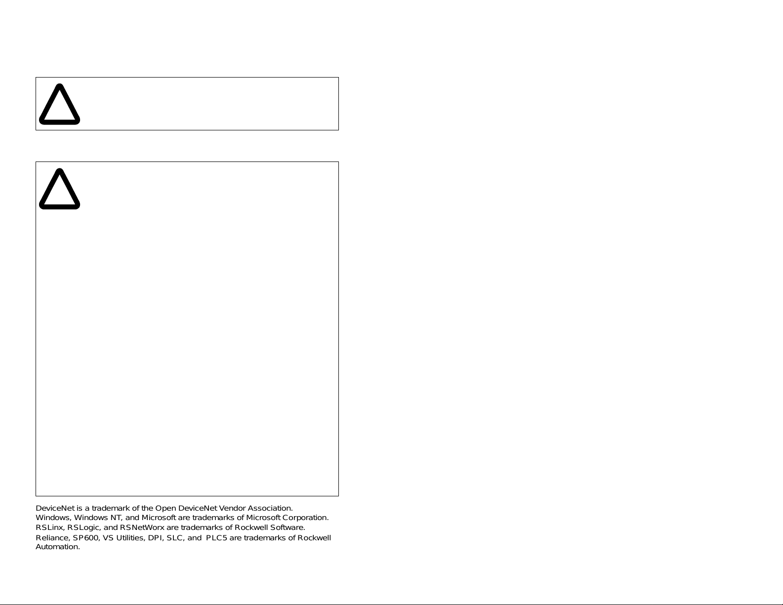
2.1 DeviceNet Adapter Components
1
2
4
2
3
Status Indicators
➀
DPI Connector A 20-pin, single-row shrouded male
➁
DeviceNet Connec tor A 5- pi n co nne ctor to which a 5-pin lin ear
➂
Node Address Switches Switches for setting the node address.
➃
Data Rate Switch
➄
Figure 2.1 – Components of the DeviceNet Adapter
Getting Started
Three LEDs that indicate the status of the
connected drive, adapter, and network.
Refer to Chapter 8, Troubleshooting.
header. An Internal Interface cable is
connected to this connector and a
connector on the drive. See table 2.2.
plug can be connected.
Switch for setting the DeviceNet data rate
at which the adapter communicates.
5
2-1
Page 16

2.2 Required Equipment
Table 2.2 lists the equipment shipped with the DeviceNet adapter.
When you unpack the adapter, verify that the package includes all
of these it ems.
Table 2.2 – Equipment Shipped with the DeviceNet Adapter
Item Description
DeviceNet adapter
2.54 cm (1 in) and 15.24 cm (6 in) Internal Interface cables
(Only one cable is needed to connect the adapter to the drive)
Five-pin linear DeviceNet plug (connected to the DeviceNet
connector on the adapter)
Grounding wrist strap
DeviceNet Adapter User Manual (D23478)
Table 2.3 lists user-supplied equipment also required to install and
configure the DeviceNet adapter.
Table 2.3 – Required User-Supplied Equipment
Item Description
A small flathead screwdriver
DeviceNet cable
• Thin cable with an outside diameter of 6.9 mm (0.27 in.) is
recommended
Configuration tool, such as:
•LCD OIM
• VS Utilities
• RSNetWorx for DeviceNet
• Serial Converter
Computer with a DeviceNet communications adapter installed
(such as 1784-PCD, 1784-PCID, 1784-PCIDS, or 177-KFD)
Controller configuration software (examples: RSLogix5,
RSLogix500, or RSLogix 5000)
2-2
DeviceNet Adapter for use with DPI AC Drives
Page 17

2.3 Installation Checklist
This section is designed to help experienced users start using the
DeviceNet adapter. If you are unsure how to complete a step, refer
to the referenced chapter.
Step Action Refer to
✔
1
❒
❒
❒
❒
❒
❒
Review the safety precautions for the
adapter.
2
Verify that the SP600 drive is properly
installed.
3
Commission the adapter.
Set a unique node address and the
appropriate data rate using the swit che s o n
the adapter. If desired, you can disable the
switches and use parameter settings
instead.
4
Install the adapter.
Verify that the SP600 drive and DeviceNet
network are not powered. Then, connect
the adapter to the network using a
DeviceNet cable and to the drive using the
Internal Interface cable. Use the captive
screws to secure and ground the ada pter to
the drive.
5
Apply power to the adapter.
The adapter receives power from the drive
and network. Apply power to the network
and to the drive. The status indicators
should be gre en. If they fla sh re d, there is a
problem. Refer to Chapter 8,
Troubleshooting.
6
Configure the adapter for your
application.
Set the parameters for the following
features as required by your application:
• Node address and data rate (if the Data
Rate switch is set to “PGM”).
• I/O configuration.
• Change of State, Cyclic, or polled I/O
data exchange.
• Master-slave or peer-to-peer hierarchy.
• Fault actions.
Throughout
this manual
SP600 AC
Drive User
Manual
Chapter 3,
Installing
the
DeviceNet
Adapter
Chapter 3,
Installing
the
DeviceNet
Adapter
Chapter 3,
Installing
the
DeviceNet
Adapter
Chapter 4,
Configuring
the
DeviceNet
Adapter
Getting Started
2-3
Page 18

Step Action Refer to
✔
7
❒
❒
❒
Apply power to the DeviceNet master
and other devices on the network.
Verify that the master and network are
installed and functi oning in accordanc e with
DeviceNet st andards, a nd then apply p ower
to them.
8
Configure the scanner to communicate
with the adapter.
Use a network tool such as RSNetWorx for
DeviceNet to configure the scanner on the
network. Make sure to:
• Set up the scan list.
• Map the adapter data to the scan list.
• Save your DeviceNet configu ra tion to the
scanner and a file.
9
Create a ladder logic program.
Use a programming tool such as RSLogix
to create a ladder logic program that
enables you to do the following:
• Control the adapter and connected drive.
• Monitor or configure the drive using
Explicit Messages.
Device N et
Cable
System
Planning
and
Installation
Manual
Chapter 5,
Configuring
the Scanner
Chapter 6,
Using I/O
Messaging
Chapter 7,
Using
Explicit
Messaging
2-4
DeviceNet Adapter for use with DPI AC Drives
Page 19
C
HAPTER
Installing the
DeviceNet Adapter
Chapter 3 provides instructions for installing the DeviceNet adapter
in an SP600 drive.
3.1 Preparing for an Installation
Before installing the DeviceNet ada pter:
• Read the
DN-2.5, and the
Installation Manual
provide information on selecting cables, setting up a network, and
network basics.
• Verify that you have all required equipment. R efer to chapter 2,
Getting Started.
3.2 Commissioning the DeviceNet
Adapter
DeviceNet Product O verview Manual
DeviceNet Cable System Planning and
, Publication DN-6.7.2. These manuals will
, Publication
3
To commission the adapter, you must set a unique node address
and the data rate that is used b y the net work. (Ref er to the Glossary
for details about data rates and node addresses.)
Important:
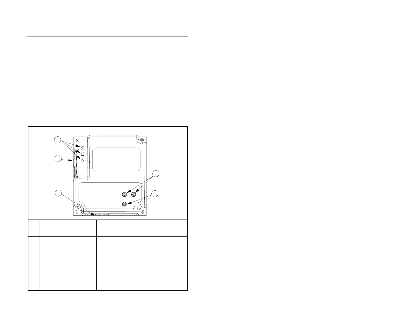
Step 1. Set the node address switches as shown in figure 3.1.
Installing the DeviceNet Adapter
New settings are recognized o nly when po wer is appli ed
to the adapter. If you change a setting, cycle power.
ATTENTION:
ESD- (Electrostatic Discharge) sensitive parts that
!
can be damaged if you do not follow ESD control
procedures. Static con trol p recaut ions are r equired
when handling the ada pter. F ailure to obs erve these
precautions could result in damage to equipment.
The DeviceNet adapter contains
3-1
Page 20
1
0
9
2
8
Tens
Digit
3
7
2
3
4
1
0
5
6
4
9
5
6
7
8
Ones
Digit
Setting Description
0-63 Node address used by the adapter if switches are
enabled. The default switch setting is 63. Node
address 63 is also the default address used by all
uncommissioned devices. Do not use this address
as the final adapter addr ess.
Important:
If the Data Rate switch is set to “PGM”
(Program), the adapter will use the setting of DN
Addr Cfg (3) for the node address. The default
parameter setting is 63. Refer to chapter 4,
Configuring the Devic eNet Adap ter.
64-99 Do not use. The adapter does not recognize these
addresses.
Figure 3.1 – Setting the Node Address
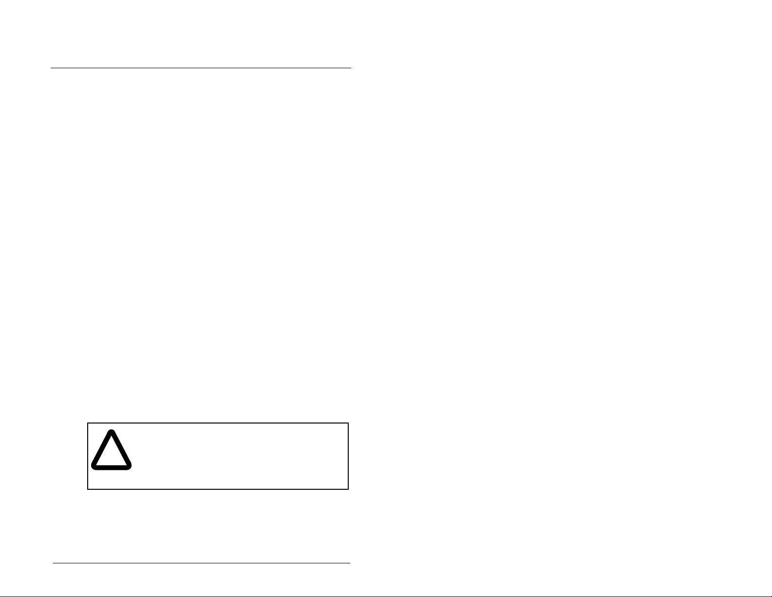
Step 2. Set the data rate switch as shown in figure 3.2
3-2
500K
250K
125K
PGM
AUTO
Setting Description
Auto The adapter is set to the data rate used by other
network devices. Another device on the network
must be set to a data rate.
125 K
The adapter is set to the respective data rate.
250 K
500 K
PGM The adapter uses the setting of DN Rate Cfg (5) for
the data rate. Refer to chapter 4, Conf iguring the
DeviceNet Adapter.
Figure 3.2 – Setting the Data Rate
DeviceNet Adapter for use with DPI AC Drives
Page 21
3.3 Connecting the Adapter to the
Network
ATTENTION:
that can cause injury or death. Remove all power
!
Step 1. Remove power from the network and drive.
Step 2. Use static control precautions.
Step 3. Connect a DeviceNet cable to the network, and route it
Important:
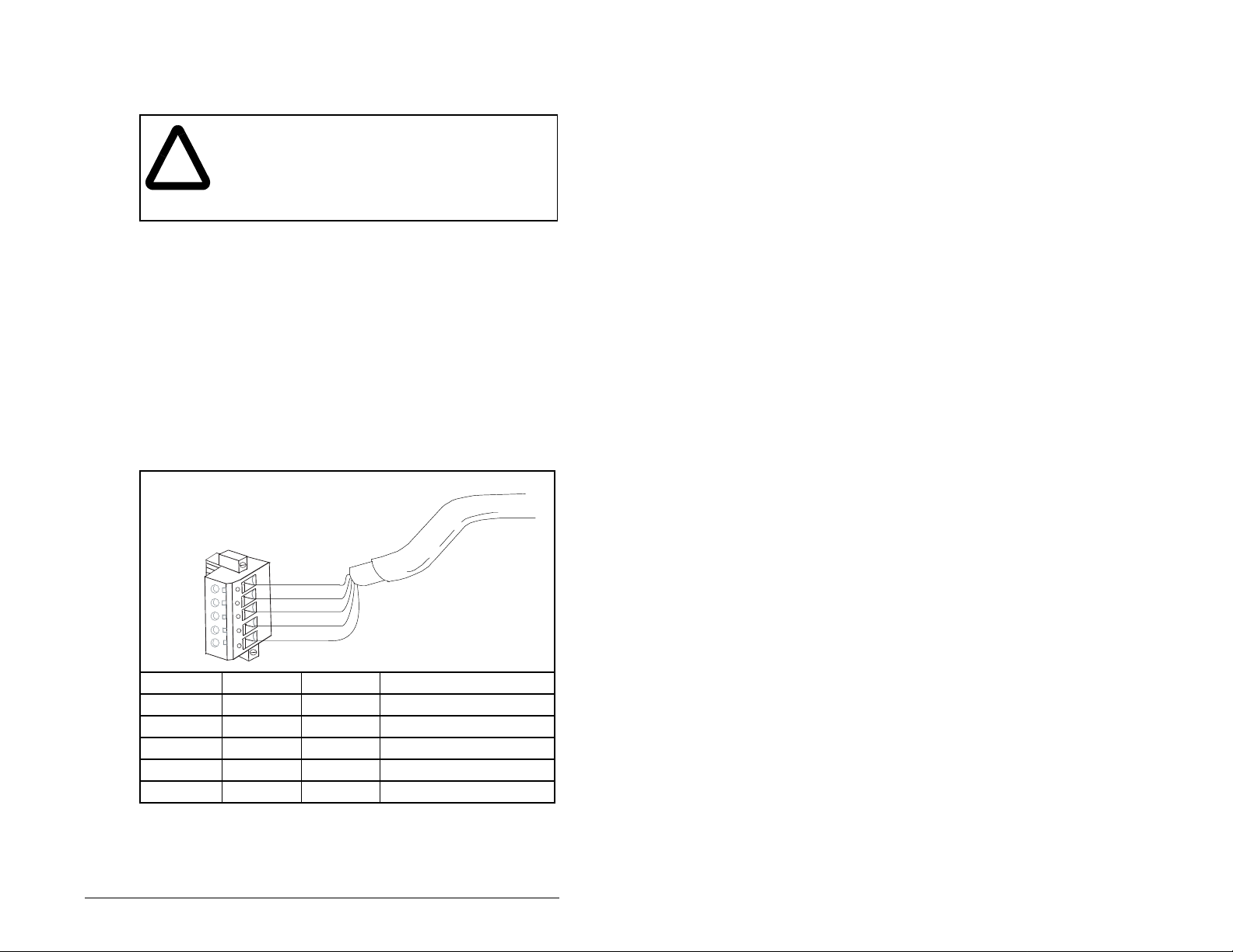
Step 4. Connect a 5-pin linear plug to the DeviceNet cable. Refer
from the drive, and then verify power has been
removed before installing or removing a DeviceNet
adapter. F ailure to observe thes e precautio ns could
result in severe bodily injury or loss of life.
through the bottom of the SP600 drive. DeviceNet thin
cable with an outside diameter of 6.9 mm (0.27 in.) is
recommended. (See figure 3.5.)
Maximum cable length depends on data rate. Refer to
data rate
to figure 3.3.
Note that a 10-pin linear plug is not supported. Use the
5-pin linear plug shipped with the adapter.
5
4
3
2
1
The drive may contain high voltages
in the Glossary.
Red
White
Bare
Blue
Black
Terminal Color Signal Function
5 Red V+ Power Supply
4 White CAN_H Signal High
3 Bare SHIELD Shield
2 Blue CAN_L Signal Low
1BlackV– Common
Figure 3.3 – Connecting a 5-Pin Linear Plug to the Cable
Step 5. Connect the DeviceNet cable to the adapter and secure it
with the two screws (see figure 3.4).
Installing the DeviceNet Adapter
3-3
Page 22
3.4 Connecting the Adapter to the Drive
Step 1. Remove power from the drive and network.
Step 2. Use static control precautions.
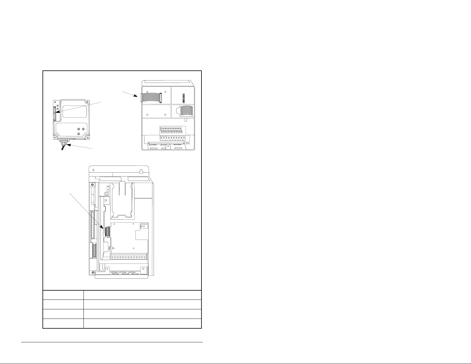
Step 3. Connect the Internal Interface cable to the DPI port on the
drive and then to the DPI connector on the adapter.
➀
➁
➂
DeviceNet Adapter
➃
SP600 AC Drive
25-40 HP @ 460 V
➀
➁
➂
➃
Figure 3.4 – DPI Ports and Internal Interface Cables
15.24 cm (6 in.) Internal Interface cable
DPI Connector
DeviceNet cable
2.54 cm (1 in.) Internal Interface cable
SP600 AC Drive
1-20 HP @ 460 V
3-4
DeviceNet Adapter for use with DPI AC Drives
Page 23
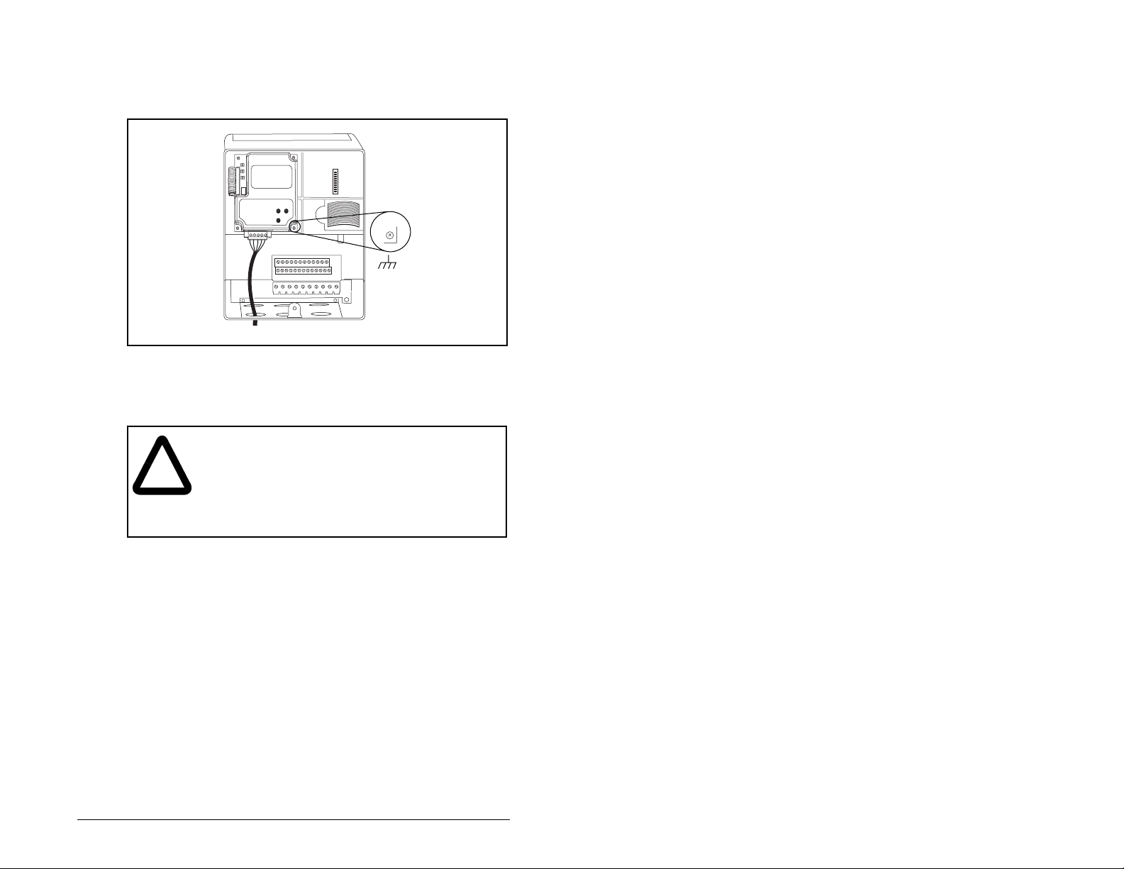
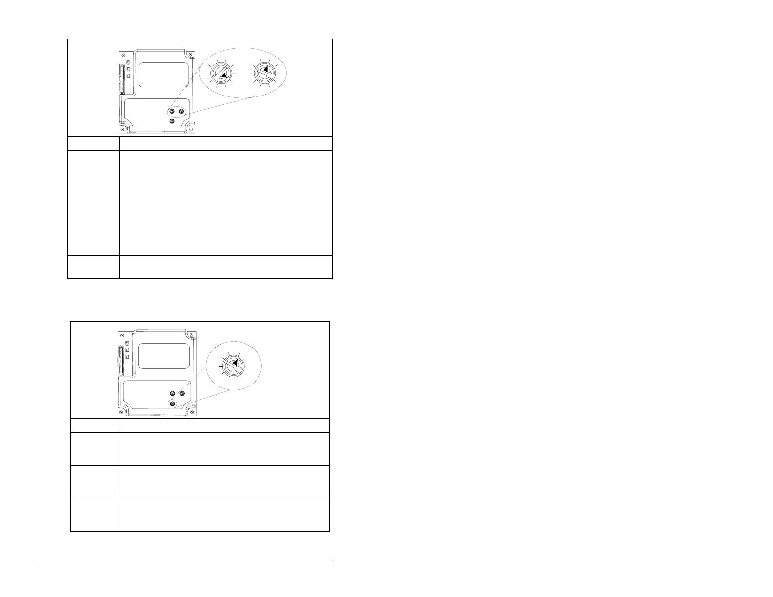
Step 4. Mount the adapter on the drive, using the four captive
Important:
screws to secure it in place and ground it to the drive.
On an SP600 drive, tighten the screw in the lower right
hole to ground the adapter.
SP600 AC Drive
Figure 3.5 – Mounting and Grounding the DeviceNet Adapter
3.5 Applying Power
ATTENTION:
you fail to verify th at par ameter s etting s and s wi tch
!
Step 1. Close the door or reinstall the cover on the drive. The
Step 2. Ensure that the adapter will have a unique address on the
Step 3. Apply power to the network.
Step 4. Apply power to the drive. The adapter receives its power
Installing the DeviceNet Adapter
settings are compa tible with y our applica tion. V erify
that settings are compatible with your application
before applying power to the drive. Failure to
observe these precautions could result in severe
bodily injury or loss of life.
status indicators can be viewed on the front of the drive
after power has been applied .
network and is set at the correct da ta rate or to autoba ud. If
a new data rate or address is needed, reset its switches
(refer to section 3.2).
from the connected drive and network. When you apply
power to the product and network for the first time, the
status indicators should be green after an initialization. If
the status indicators are red, there is a problem. Refer to
chapter 8, Troubleshooting the DeviceNet Adapter and
Network.
Unpredictable ope ration ma y occur if
3-5
Page 24

Step 5. If the data rate switch is set to “PGM,” use a configuration
Step 6. Apply power to the master device (scanner) and other
tool to set the data rate and node address parameters in
the adapter (see chapter 4, Configuring the DeviceNet
Adapter). If you are using RSNetWorx for DeviceNet, you
need to create a point-to-point connection to the drive.
devices on the networ k.
3-6
DeviceNet Adapter for use with DPI AC Drives
Page 25

C
Configuring the
DeviceNet Adapter
Chapter 4 provides instructions and information for setting the
parameters in the DeviceNet adapter.
For a list of parameters, refer to Appendix B, DeviceNet Adapter
Parameters. For definitions of terms in this chapter, refer to the
Glossary.
4.1 Configuration Tools
The DeviceNet adapter stores parameters and other information in
its own non-volatile memory. Therefore, you must access the
adapter to view and edit its parameters. Table 4.1 lists the tools that
can be used to access the adapter parameters.
Table 4.1 – Configuration Tools
Tool Refer To:
VS Utilities Software VS Utilities online help
LCD OIM Section 4.2
RSNetWorx for DeviceNet Section 4.3
HAPTER
4
RSNetWorx for DeviceNet (version 2.22.18) and RSLinx (version
2.10.118) were u sed for exam pl es in this manual. Different v e rsio ns
of software may differ in appearance and procedures.
Note that explicit messaging can also be used to configure a
DeviceNet adapter and drive. Refer to Chapter 7, Using Explicit
Messaging.
Configuring the DeviceNet Adapter
4-1
Page 26
4.2 Using the LCD OIM to Configure the
Adapter
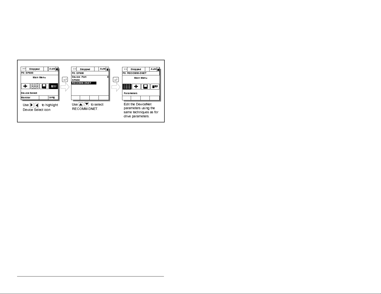
Use the procedure in figure 4.1 to access the parameters on the
DeviceNet adapter using the LCD OIM. If you are unfamiliar with
the operation of the LCD OIM, refer to the SP600 AC Drive User
Manual (D2-3485) f or mo re information.
!!
6WRSSHG
3 63
0DLQ 0HQX
'HYLFH 6HOHFW
0RQLWRU
8VH WR KLJKOLJKW
'HYLFH 6HOHFW LFRQ
$XWR
/DQJ
!!
6WRSSHG
3 63
'HYLFH 3RUW
63
5(&200'1(7
8VH WR VHOHFW
5(&200'1(7
$XWR
!!
6WRSSHG
3 5(&200'1(7
0DLQ 0HQX
3DUDPHWHUV
(GLW WKH 'HYLFH1HW
SDUDPHWHUV XVLQJ WKH
VDPH WHFKQLTXHV DV IRU
GULYH SDUDPHWHUV
Figure 4.1 – Accessing the DeviceNet Parameters using the LCD OIM
4.3 Using RSNetWorx for DeviceNet
RSNetWorx for DeviceNet is a Rockwell Software application that
can be used t o set up DeviceNet net wo rks and confi gure c onnec ted
devices.
4.3.1 Setting Up RSLinx for RSNetWorx for
DeviceNet
To use RSNetWorx for DeviceNet, you must first set up a driver in
RSLinx. The driver provides a communications link between the
computer and DeviceNet network. See table 4.2 and figure 4.2 for
this procedure.
$XWR
4-2
DeviceNet Adapter for use with DPI AC Drives
Page 27
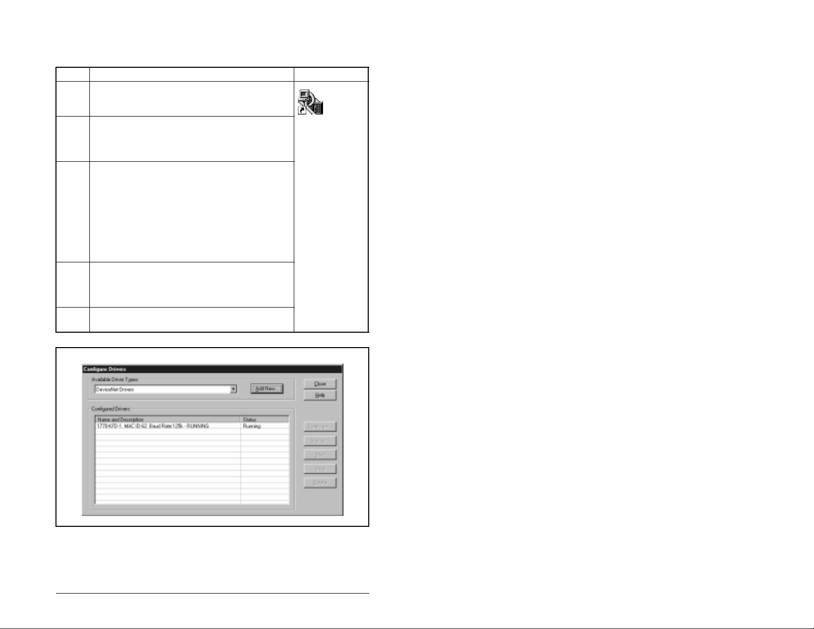
Table 4.2 – Procedure for Setting Up RSLinx for RSNetworx for DeviceNet
Step Action Icon
1. Start RSLinx, and select
Configure Drivers
Drivers dialog box. See figure 4.2.
Communications >
to display the Configure
Shortcut to
RSLinx
2. In the Available Dr iver Types box, select
DeviceNet Drivers
, and then click
Add New
.
The DeviceNet Driver Selection dialog box
appears.
3. In the Available DeviceNet Drivers list, select
the adapter connected to your computer, and
then click
. A Driver Confi guration dialog
Select
box appears.
Configure the driver for your computer and
network settings, and then click OK. The
Configure Drivers dialog box reports the
progress of the configuration. Then, the Add
New RSLinx Driver dialog box appears.
4. Type a name (if desired), and then click OK.
The Configure Drivers dialog box reappears,
and the new driver is in the Confi gu r ed Driv ers
List.
5. Click
to close the dialog box. Leave
Close
RSLinx running.
Figure 4.2 – Configure Drivers Dialog Box with a Configured Driver
Configuring the DeviceNet Adapter
4-3
Page 28
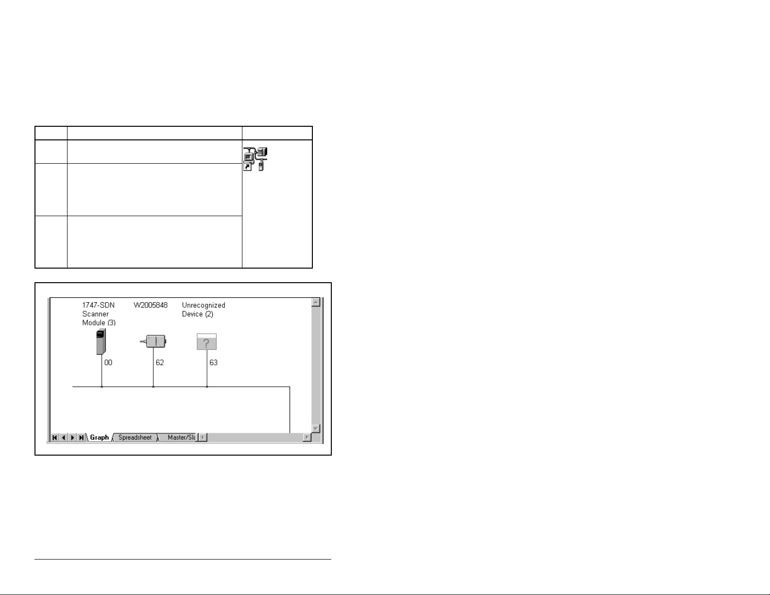
4.3.2 Going Online with RSNetWorx for DeviceNet
You can view the devices on a De viceNet netw ork by going onlin e. A
device may appear as an unrecognized device (node 63 in figure
4.3) if RSNetWorx for DeviceNet does not have an Electronic Data
Sheet (EDS) file for it. See table 4.3 for the procedure to view
devices.
Table 4.3 – Viewing Devices on the DeviceNet Network using RSNetWorx
Step Action Icon
1. After setting up a driver in RSLinx, start
RSNetWorx for DeviceNet.
2. Select
3. Click OK to go online. The devices on the
Network > Online
for Network dialog box appears, RSLinx
has multiple drivers configured. Select
your DeviceNet network, and click OK. A
prompt appears.
network appear in the Configuration View.
You can select Graph, Spreadsheet, or
Master/Slave views. Figure 4.3 shows a
sample network in a Graph view.
. If the Browse
Shortcut to
RSNetWorx
4-4
Figure 4.3 – Sample DeviceNet Network (Graph View)
DeviceNet Adapter for use with DPI AC Drives
Page 29
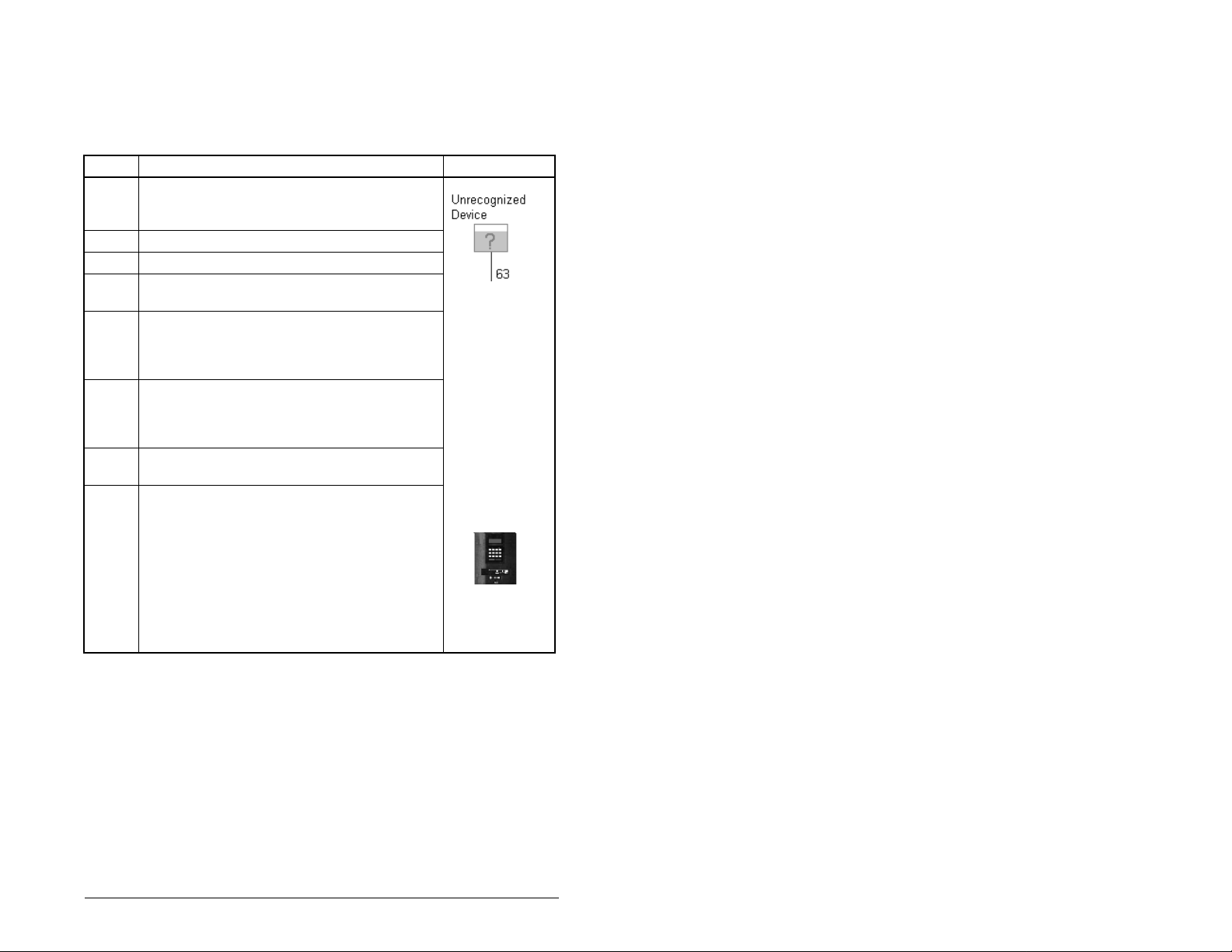
4.3.3 Creating an Electronic Data Sheet (EDS) File
If the adapter and drive appear as an unrecognized device, create
an EDS file for it using the procedure in table 4.4.
Table 4.4 – Procedure for Creating an EDS File
Step Action Icon
1. Right-click the “Unrecognized Device” icon ,
and select
EDS Wizard (figure 4.4) appears.
2. Click
3. Select
4. Type a description (if desired), and then click
Next
5. Under Polled, select
Input Size and Output Size boxes, and then
click
from the drive and adapter.
6. Click
node. We recommend that you use the icon f or
your product. You can change icons by clic king
Change icon
7. Click
Next
8. Click
icon represents the SP600 drive and adapter
in the Configuration View.
Important:
(versions 2.22.18 and earlier) replaces 32-bit
values with exponential values. For the EDS
file to work in RSNetWorx, you must edit the
EDS file, replacing exponential values with
32-bit val ues (typic ally 42 949 67295 ), and then
restart RSNetWorx.
Register Device
to display the next step.
Next
Upload EDS
.
. RSNetWorx will upload the EDS fil e
Next
to display the icon options for the
Next
to view a summary, and then click
Next
again to accept it.
to finish the EDS creation. A new
Finish
RSNetWorx for DeviceNet
, and then click
.
in the menu. The
Enabled
, type 4 in the
Next
.
SP600
AC Drive
Configuring the DeviceNet Adapter
4-5
Page 30
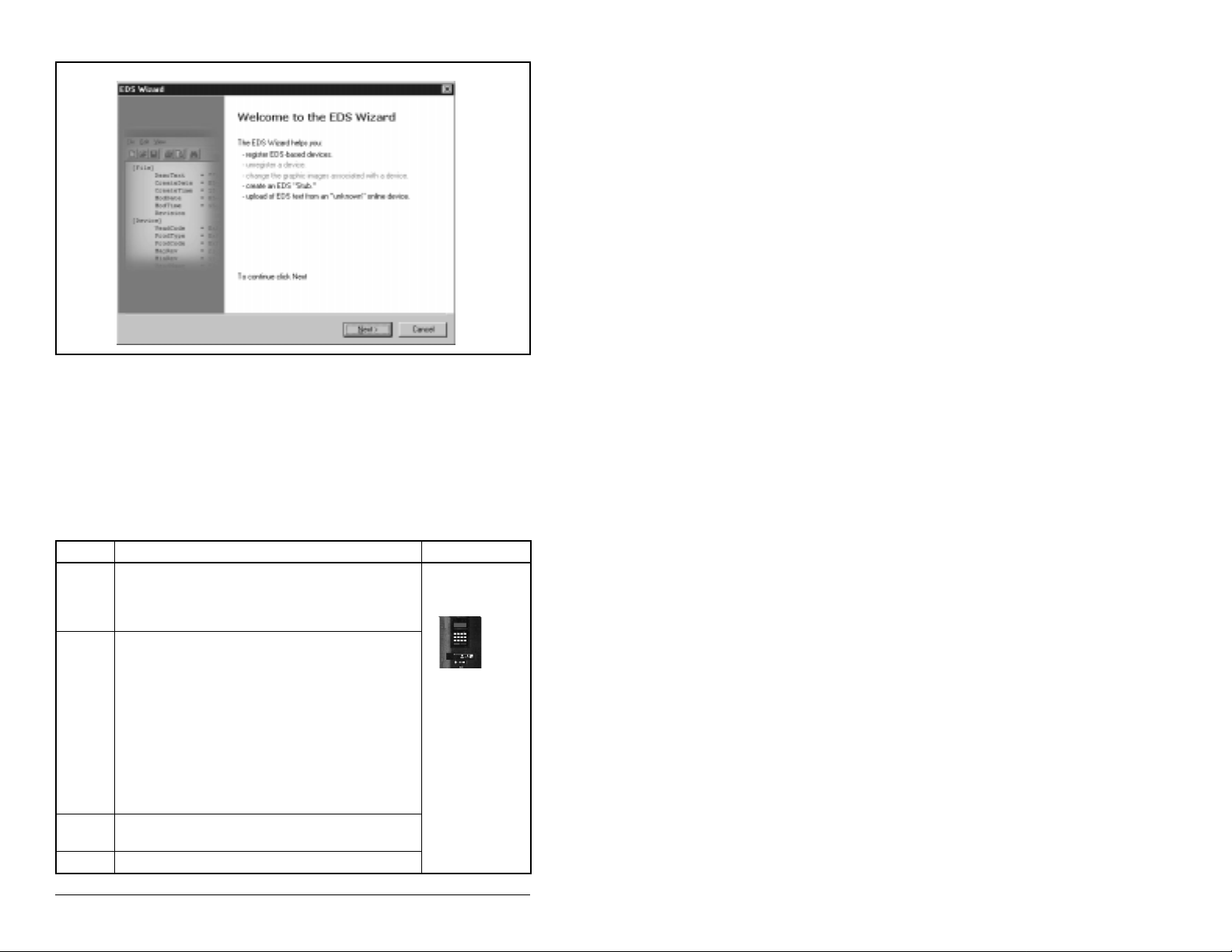
Figure 4.4 – EDS Wizard Screen
4.3.4 Accessing and Editing Parameters
Parame ters i n th e d rive and adapter can be edited with RSNetWorx
using the procedure in table 4.5. The adapter parameters are
appended to the list of drive parameters. In figure 4.5, for example,
the drive has 387 parameters, so parameter 388 is the first adapter
parameter.
Table 4.5 – Procedure to Access and Edit Parameters Using RSNetWorx
Step Action Icon
1. After creating an EDS file, right-click on the
2. Click the
3. In the Current Value column, double-click a
4. Click
icon for the SP600 drive and adapter and
select
Properties
appears.
Device Parameters
If an EDS Editor message appears, click
to load the parameter values in the
Upload
drive to the computer.
Parameters are displayed in numerical order
under Par amet er. You can either scroll through
the list or select a specif ic group of paramete rs
in the Groups box. The available groups and
the numbers of the adapter parameters will
vary based on the type of drive that is
connected to the adapter.
value to edit it.
Apply
. The SP600 Drive dialog bo x
tab (figure 4.5).
to save changes to the device.
SP600
AC Drive
4-6
DeviceNet Adapter for use with DPI AC Drives
Page 31

SP600 Standard
Figure 4.5 – Sample SP600 Drive Dialog Box (Drive Parameters Tab)
4.4 Setting the Node Address
If the adapter Data Rate switch is set to “PGM,” the value of DN
Addr Cfg (3) determines the node address.
Step 1. Set the v alue of DN Add r Cfg (3) to a unique node addre ss.
See figure 4.6. Do not use node address 63 because all
new devices use it as the default address. Address 63 is
also used for Automatic Device Replacement (ADR).
Port 5 Device
RECOMM-DNET
Parameter #: 3
DN Addr Cfg
63
Figure 4.6 – DeviceNet Node Address Screen on an LCD OIM
Step 2. Reset the adapter. Refer to sec tion 4.10, Resetting the
Adapter, for this procedure.
If you are using RSNetW orx f or De viceN et, select
Browse Path
Configuring the DeviceNet Adapter
to see the new address; then delete the old address.
Default = 63
0 <> 63
Network > Single
4-7
Page 32

4.5 Setting the Data Rate
If the adapter Data Rate switch is set to “PGM,” the value of
DN Rate Cfg (05) determines the DeviceNet data rate. See figure
4.7. The Autobaud setting will detect the data rate used on the
network if another device is setting the data rate. Your application
may require a different setting.
Step 1. Set the value of DN Rate Cfg (05 ) to t he data rate at which
your network is operating.
Port 5 Device
RECOMM-DNET
Parameter #: 5
DN Rate Cfg
3
Autobaud
Figure 4.7 – DeviceNet Data Rate Screen on an LCD OIM
Value Baud Rate
0 125 kbps
1 250 kbps
2 500 kbps
3 Autobaud (Default)
Step 2. Reset the adapter. Refer to section 4.10 for this procedure.
4.6 Setting the I/O Configuration
The I/O configuration determines the type of data sent to the drive.
Logic Command/Status, Reference/Feedback, and Datalinks may
be enabled or disabled. A “1” enables the I/O. A “0” disables it.
Step 1. Set the bits in DPI I/O Confg (13). Bit 0 is the right-most bit.
In figure 4.8, it is highlighted and equals “1.”
Port 5 Device
RECOMM-DNET
Parameter #: 13
DPI I/O Config
xxxx xxxx xxx0 000
Cmd/Ref b00
1
Bit Description
0 Logic Command/Reference (Default)
1 Datalink A
2 Datalink B
3 Datalink C
4 Datalink D
5-15 Not Used
4-8
Figure 4.8 – I/O Configuration Screen on an LCD OIM
Step 2. Set a master-slave or peer-to-peer hierarchy. Refer to
section 4.7.
DeviceNet Adapter for use with DPI AC Drives
Page 33

Step 3. If you enabled Logic Command/Reference, configure the
parameters in the drive to accept the logic and reference
from the adapter . F or e xample , set Sp eed Ref A Sel (90 ) in
an SP600 drive to “Network” so that the drive uses the
reference from the adapter.
Step 4. If you enabled one or more Datalinks, configure
parameters in the drive to determine the source and
destination of data in the Datalink(s). Also, ensure that the
DeviceNet adapter is the only adapter using the enabled
Datalink(s).
Step 5. Reset the adapter. Refer to the section 4.10 for this
procedure.
4.7 Selectin g Mas ter-Sla ve or
Peer-to-Peer
A hierarchy determines the type of device with which the adapter
exchanges data. In a
master-slave
exchanges data with a scanner. In a
adapter can exchange data with one or more DeviceNet adapter(s)
connected to SP600 drives that have similar data structures.
4.7.1 Setting a Master-Slave Hierarchy
Step 1. Enable the desired I/O in DPI I/O Config (13). Refer to
Step 2. Set the bits in M-S Input (25). This parameter determines
figure 4.8.
the data transmitted from the scanner to the drive. A “1”
enables the I/O. A “0” disables the I/O. Bit 0 is the
right-most bit. In figure 4.9, it is highlighte d and equa ls “1.”
hierarchy, an adapter
peer-to-peer
hierarchy, an
Port 5 Device
RECOMM-DNET
Parameter #: 25
M-S Input
xxxx xxxx xxx0 000
Cmd/Ref b00
Figure 4.9 – Master-Slave Input Screen on an LCD OIM
Configuring the DeviceNet Adapter
Bit Description
0 Logic Command/Reference (Default)
1 Datalink A Input
2 Datalink B Input
3 Datalink C Input
1
4 Datalink D Input
5-15 Not Used
4-9
Page 34

Step 3. Set the bits in M-S Output (26). This parameter determines
the data transmitted from the drive to the scanner. A “1”
enables the I/O. A “0” disables the I/O. Bit 0 is the
right-most bit. In figure 4.10, it is highlighted and equals
“1.”
Port 5 Device
RECOMM-DNET
Parameter #: 26
M-S Output
xxxxxxxxxxx0000
Status/Fdbk b00
Figure 4.10 – Master-Slave Output Screen on an LCD OIM
1
Bit Description
0 Status/Feedback (Default)
1 Datalink A Output
2 Datalink B Output
3 Datalink C Output
4 Datalink D Output
5-15 Not Used
Step 4. Reset the adapter. Refer to section 4.10 for this procedure.
The adapter is ready to receive I/O from the master (i.e., scanner).
You must now configure the scanner to recognize and transmit I/O
to the adapter. Refer to chapter 5, Configuring the Scanner.
4.7.2 Setting an Adapter To Transmit Peer-to-Peer
Data
Step 1. Verify that Peer Out Enable (41) is set to Off. This
parameter must be set to Off while you configure some of
the peer output parameters. See figure 4.11.
Port 5 Device
RECOMM-DNET
Parameter #: 41
Peer Out Enable
0
Off
Value Setting
0 Off (Default)
1On
4-10
Figure 4.11 – Peer Out Enable Screen on an LCD OIM
Step 2. Select the source of the data to output to the network in
Peer A Output A (39). If you are transmitting a 32-bit
Reference or 32-bit Datalink, only Peer A Output will be
available. Peer B Output cannot be used. See figure 4.12.
DeviceNet Adapter for use with DPI AC Drives
Page 35

Port 5 Device
RECOMM-DNET
Parameter #: 39
Peer A Output
1
Cmd/Ref
Figure 4.12 – Peer A Output Screen on an LCD OIM
Value Description
0 Off (Default)
1 Logic Command/Reference
2-5 Datalink A, B, C, or D
Input
6-9 Datalink A, B, C, or D
Output
Step 3. If desired, sel ec t an add itional source of the d ata to o utp ut
to the network in Peer B Output (40). See figure 4.13.
Port 5 Device
RECOMM-DNET
Parameter #: 40
Peer B Output
2
DL A Input
Figure 4.13 – Peer B Output Screen on an LCD OIM
Value Description
0 Off (Default)
1 Logic Command/Reference
2-5 Datalink A, B, C, or D
Input
6-9 Datalink A, B, C, or D
Output
Step 4. Set Peer Out Time (42) and Peer Out Skip (43) to establish
the minimum and maximum intervals between Peer
messages. The minimum interval is set in Peer Out Time
(42). The maximum interval is the value of Peer Out Time
(42) multiplied by the value of Peer Out Skip (43). See
figure 4.14.
Port 5 Device
RECOMM-DNET
Parameter #: 42
Peer Out Time
10.00 Secs.
0 <> 10.00
Port 5 Device
RECOMM-DNET
Parameter #: 43
Peer Out Skip
1
1 <>16
Figure 4.14 – Min Peer TX Time and Peer Out Skip Screens on an LCD OIM
Step 5. Set Peer Out Enable (41) to On. The adapter will transmit
the data selected in Peer A Output (39) and Peer B Output
(40) to the network. Anoth er adapter must be c onfigured to
receive the data.
Configuring the DeviceNet Adapter
4-11
Page 36

4.7.3 Setting an Adapter To Receive Peer-to-P eer Data
Step 1. Verify that Peer Inp Enable (37) is set to Off. This
parameter must be set to Off while you configure some of
the peer input parameters. See figure 4.15.
Port 5 Device
RECOMM-DNET
Parameter #: 37
Peer Inp Enable
0
Off
Figure 4.15 – Peer Input Enable Screen on an LCD OIM
Value Setting
0 Off (Default)
1On
Step 2. Select the node from which you want to receive data in
Peer Note to Inp (35). Valid nodes must have
RECOMM-DNET adapters connected to drives wit h similar
data structures. See figure 4.16.
Port 5 Device
RECOMM-DNET
Parameter #: 35
Peer Node to Inp
0
0 <>63
Figure 4.16 – Peer Node to Input Screen on an LCD OIM
Default = 0
4-12
Step 3. Select the destination of the data that is input to the drive
in Pee r A Input ( 30). If y ou are receiv ing a 32 -bit Ref erence
or 32-bit Datalink, only Peer A Input will be available. Peer
.
B Input cannot be used. See figure 4.17.
Port 5 Device
RECOMM-DNET
Parameter #: 30
Peer A Input
1
Cmd/Ref
Figure 4.17 – Peer A Input Screen on an LCD OIM
DeviceNet Adapter for use with DPI AC Drives
Value Description
0 Off (Default)
1 Logic Command/Reference
2 5 Datalink A, B, C, or D
Input
Page 37

Step 4. If desired, select the destination of the data to input to the
drive in Peer B Input (31). See figure 4.18.
Port 5 Device
RECOMM-DNET
Parameter #: 31
Peer B Input
2
DL A Input
Figure 4.18 – Peer B Input Screen on an LCD OIM
Value Description
0 Off (Default)
1 Logic Command/Reference
2 5 Datalink A, B, C, or D
Input
Step 5. If you are receiving a Logic Command, set the bits in it that
should be used in Peer Cmd Mas k (3 2). T he b it d efi nitions
for the Logic Command word will depend on the drive to
which the adapter is connected. Refer to the drive
documentation.
If the adapter receives a Logic Command from both a
master device and a peer device, each command bit must
have only one source. The source of command bits set to
“0” will be the master device. The source of command bits
set to “1” will be the peer device. See figure 4.19.
Port 5 Device
RECOMM-DNET
Parameter #: 32
Peer Cmd Mask
000000000000000
Bit 0 B00
0
Value Description
0 Ignore this command bit.
(Default)
1 Use this command bit.
Figure 4.19 – Peer Logic Command Mask Screen on an LCD OIM
Step 6. If you are receiving a Reference, set the scale in Peer Ref
Adjust (33). It can be scaled between 0.00 and 199.99%.
See figure 4.20.
ATTENTION:
(33) take effect immediately. A drive receiving its
!
Reference from peer I/O will receive the newly
scaled Reference, resulting in a change of speed.
Failure to observe this precaution could result in
bodily injury or damage to, or destruction of,
equipment.
Configuring the DeviceNet Adapter
Note that changes to Peer Ref Adjust
4-13
Page 38

Port 5 Device
RECOMM-DNET
Parameter #: 33
Peer Ref Adjust
0.00 %
0.00 <> 199.99
Figure 4.20 – Peer Reference Adjust Screen on an LCD OIM
Default = 0.00%
Step 7. Set Peer Inp Timeout (36) to the maximum amount of time
the adapter will wait for a message before timing out. See
figure 4.21.
Important:
This value mu st be gr eater tha n the produc t of Peer Out
Time (42) multiplied by Peer Out Skip (43) in the
adapter from which you are receiving I/O.
Port 5 Device
RECOMM-DNET
Parameter #: 36
Min Peer Rx Time
10.00 Secs.
0.01 <> 180.00
Figure 4.21 – Minimum Peer Receiving Time Screen on an LCD OIM
Default = 10.00 Secs
Step 8. Peer Flt Action (34) specifies the action that the adapter
will take if it times out. See figure 4.22. For details, refer to
section 4.9.
ATTENTION:
Peer Flt Action (34) lets you det ermine
the action of the adapter and connected drive if
!
communications are disrupted. By default, this
parameter faults the drive. You can set this
parameter so that the drive continues to run.
Precautions should be taken to ensure that the
setting of this parameter does not create a hazard
of injury or equipment damage. Failure to observe
these precautions could result in bodily injury or
damage to equipment.
4-14
DeviceNet Adapter for use with DPI AC Drives
Page 39

Port 5 Device
RECOMM-DNET
Parameter #: 34
Peer Flt Action
0
Fault
Figure 4.22 – Peer Fault Action Screen on an LCD OIM
Value Description
0 Fault (Default)
1Stop
2 Zero Data
3 Hold Last
4 Send Flt Cfg
Step 9. Set Peer Inp Enable (37) to On. The adapter is now
configured to receive I/O from the specified node. Ensure
that the specified node is configured to transmit I/O.
4.8 Selecting COS, Cyclic, or Polled I/O
The data exc hange (someti mes calle d allocati on) is the me thod that
the adapter uses to exchange data on the DeviceNet network. The
adapter can be configured to use one of the following data
exchanges:
• COS (change of state)
• Polled and COS
•Cyclic
• Polled and cyclic
•Polled
If “polled and COS” or “polled and cyclic” is used, the adapter
receives the I/O from the polled messages. It transmits its Logic
Status and Feedback in COS or cyclic messages. Other data is
transmitted in polled messages.
Cyclic and polled dat a exchanges are co nfi gure d in th e sc anner, so
you only need to set the I/O configuration in the adapter. COS data
exchange must be configured in both the adapter and the scanner.
You need to set the I/O configuration and COS parameters in the
adapter.
4.8.1 Using COS (Change of State) Data Exchange
Step 1. Set bit 0 (the Logic Command/Reference bit) in DPI I/O
Config ( 13) to 1 (En abled) and bit 0 (the Logic
Status/Feedback bit) in M-S Output (26) to 1 (Enabled).
Changes to bits in the Logic Status or Feedback trigger
messages in COS data exchange. See figure 4.23.
Configuring the DeviceNet Adapter
4-15
Page 40

Port 5 Device
RECOMM-DNET
Parameter #: 13
DPI I/O Config
xxxx xxxx xxx0 000
Cmd/Ref b00
Figure 4.23 – I/O Configuration Screens on an LCD OIM
1
Port 5 Device
RECOMM-DNET
Parameter #: 26
M-S Output
xxxx xxxx xxx0 000
Status/Fdbk b00
1
Step 2. Set the bits in the Logic Status word that should be
checked for changes in COS Status Mask (27). See figure
4.24. The bit definitions f or the Status Ma sk will depend on
the drive to which you are connected. Refer to the drive
documentation.
Port 5 Device
RECOMM-DNET
Parameter #: 27
COS Status Mask
000000000000000
Bit 0 b00
Figure 4.24 – COS Status Mask Configuration Screen on an LCD OIM
1
Value Description
0 Ignore this logic bit. (Default)
1 Check this logic bit.
Step 3. Set the amount of change to the F e edbac k that is requ ired
to trigger a Change of state message in COS Fdbk
.
Change (28). See figure 4.25.
Port 5 Device
RECOMM-DNET
Parameter #: 28
COS Fdbk Change
0
0 <> 4294967295
4-16
Figure 4.25 – COS Fdbk Change Configuration Screen on an LCD OIM
The adapter is now configured for COS data exchange. You must
configure the scanner to allocate it using COS (see chapter 5,
Configuring the Scanner).
DeviceNet Adapter for use with DPI AC Drives
Page 41

4.9 Settin g a Fault Action
By default, when communications are disrupted (for example, a
cable is disconnected) or the scanner is idle, the drive responds by
faulting if it is using I/O from the network.
You can configure a different response to communication
disruptions using Comm Flt Action (10) and a different response to
an idle scanner using Idle Flt Action (11).
ATTENTION:
Action (11) let you determine the action of the
!
adapter and connecte d drive if c ommunic ations are
disrupted or the scanner is idle. By default, these
parameters fault the drive. You can set these
parameters so that the drive continues to run.
Precautions should be taken to ensure that the
settings of these pa rameters do no t create a hazard
of injury or equipment damage. Failure to observe
these precautions could result in bodily injury or
damage to, or destruction of, equipment.
Comm Flt Action (10) and Idle Flt
4.9.1 Changing the Fault Action
Set the values of Comm Flt Action (10) and Idle Flt Action (11) to
the desired responses as shown in table 4.6. See figure 4.26 for
sample LCD OIM Fault Action Screens.
Table 4.6 – Selections for Drive Response to Communication Fault
Value Action Description
0 Fault The drive is faulted and stopped. (Default)
1 Stop The drive is stopped, but not faulted.
2 Zero Data The drive is sent 0 for output data after a
3 Hold Last The drive continues in its present state after a
4 Send Flt
Cfg
communications disruption. This does not
command a stop.
communications disruption.
The drive is sent the data that you set in the fault
configuration parameters Flt Cfg Logic (15)
through Flt Cfg D2 In (24).
Configuring the DeviceNet Adapter
4-17
Page 42

Port 5 Device
RECOMM-DNET
Parameter #: 10
Comm Flt Action
0
Fault
Figure 4.26 – Fault Action Screens on an LCD OIM
Port 5 Device
RECOMM-DNET
Parameter #: 11
Idle Flt Action
0
Fault
Changes to these parame ters ta k e effect immediate ly. A reset is not
required.
4.9.2 Setting the Fault Configuration Parameters
If you set Comm Flt Action (10), Idle Flt Action (11), or Peer Flt
Action (34) to the “Send Flt Cfg,” the values in parameters shown in
table 4.7 are sent to the drive after a communications fault and/or
idle fault occurs. You must set these parameters to values required
by your application.
Table 4.7 – Fault Configuration Parameters
Parameter Name Description
15 Flt Cfg Logic A 16-bit value sent to the drive for Logic
Command.
16 Flt Cfg Ref A 32-bit value (0 – 4294967295) sent to the
17 – 24 Flt Cfg x1 In
or Flt Cfg x2
In
drive as a Re ference or Datalink.
Important:
If the drive uses a 16-bit
Reference or 16-bit Datalinks, the most
significant word of the value must be set to
zero (0) or a fault will occur.
4-18
Changes to these parame ters ta k e effect immediate ly. A reset is not
required.
DeviceNet Adapter for use with DPI AC Drives
Page 43

4.10 Resetting the Adapter
Changes to switch settings on some adapter parameters require
that you reset the adapter before the new settings take effect. You
can reset the adapter by cycling power to the drive or by using
Reset Module (9).
ATTENTION:
I/O to the drive, the drive may fault when you reset
!
Set Reset Module (9) to 1 (Reset Module). See figure 4.27.
Port 5 Device
RECOMM-DNET
Parameter #: 9
Reset Module
When you enter
reset. When you enter
adapter parameters to their factory-default settings. The value of
this parameter will be restored to
reset.
the adapter . Determine ho w your driv e will respond
before resetting a connected adapter. Failure to
observe these precautions could result in bodily
injury or damage to equipment.
1
Reset Module
Figure 4.27 – Reset Screen on an LCD OIM
1 (Reset Module)
If the adapter is transmitting control
Value Description
0 Ready (Default)
1 Reset Module
2 Set Defaults
, the adapter will be immediately
2 (Set Defaults)
, the adapter will set all
0 (Ready)
after the adapter is
Configuring the DeviceNet Adapter
4-19
Page 44

4.11 Viewing the Adapter Configuration
The parameters in table 4.8 provide information about how the
adapter is configured. You can view these parameters at any time.
Table 4.8 – Adapter Configuration Status Parameters
Number Name Description
01 DPI Port The port on the drive to which the adapter is
02 DPI Data
Rate
04 DN Addr
Actual
06 DN Rate
Actual
07 Ref/Fdbk
Size
08 Datalink
Size
12 DN Active
Cfg
connected. Usually, it is port 5.
The data rate used by DPI in the drive. It will
be either 125 kbps or 500 kbps. It is set in the
drive, and the adapter detects it.
The node address used by the adapter. This
will be one of the following values:
• The address set by the rotary switches.
• The value of DN Addr Cfg (3) if the switches
have been disabled.
• An old address of the switches or parameter
if they have been changed and the adapter
has not been reset.
The data rate used by the adapter. This will b e
one of the following values:
• The data rate set by the DIP switch.
• The value of DN Rate Cfg (5) if the switches
have been disabled.
• An old data rate of the s witches or par amet er
if they have been changed and the adapter
has not been reset.
The size of the Reference/Feedback. It will
either be 16 bits or 32 bits. It is set in the drive
and the adapter automa tical ly use s the c orrect
size.
The size of the Datalinks. It will either be 16
bits or 32 bits. It is set in the drive and the
adapter automatically uses the correct size.
Source from which the adapter node address
and data rate are taken. This will be either
switches or parameters in EEPROM. It is
determined by the settings of the switches on
the adapter.
4-20
DeviceNet Adapter for use with DPI AC Drives
Page 45

Table 4.8 – Adapter Configuration Status Parameters (Contin ued)
Number Name Description
14 DPI I/O
Active
The Reference/Feedback and Datalinks used
by the adapter. This value is the same as DPI
I/O Config (13) unless the parameter was
changed and the adapter was not reset.
Datalink C
Datalink D
Datalink A
Datalink B
Cmd/Ref
00010xxx
01234567
1=Enabled
0=Disabled
x=Not Used
Configuring the DeviceNet Adapter
4-21
Page 46

4-22
DeviceNet Adapter for use with DPI AC Drives
Page 47
C
HAPTER
Configuring the Scanner
A scanner is a separate module of a multi-module controller or a
built-in component of a single-module controller that provides
communication with an adapter connected to a network.
Chapter 5 provides instructions on how to configure a scanner to
communicate with th e De viceNet adapter and the co nnected SP600
drive.
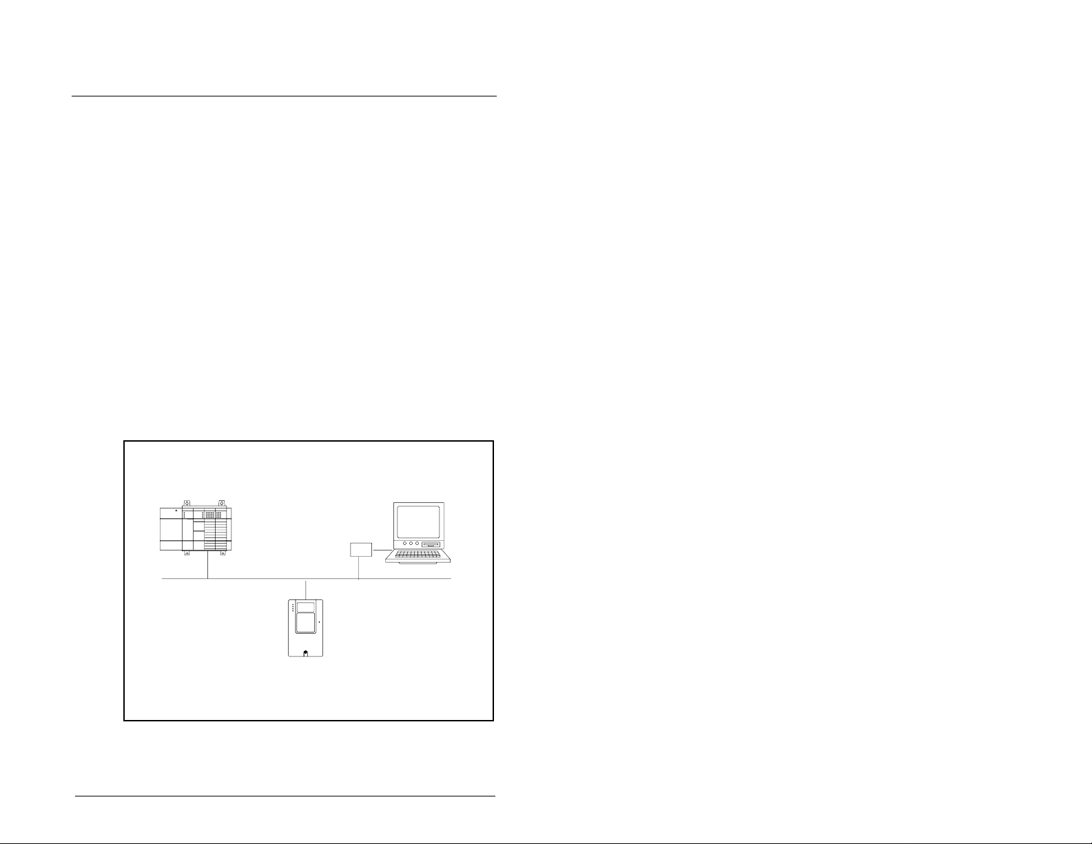
5.1 Configuring a Simple Network:
An Example
After the adapter is configured , the connected driv e and ad apter will
be a single node on the network. This chapter provides the steps
that are needed to configure a simple network like the network in
figure 5.1. In our e xample , we wil l configure the drive f or using Logic
Command/Status and Reference Feedback over the network.
5
Node 0
SCL 500 Controller with
1747-SDN- Scanner
Configuring the Scanner
Node 62
Computer with 1770-KFD and
RSNetWorx for DeviceNet
Node 1
SP600 Drive with
DeviceNet Adapter
Figure 5.1 – Sample DeviceNet Network
5-1
Page 48

5.2 Setting Up the Scan List
For the scanner to communicate with a drive, the scanner must be
configured and the drive’s node number must be added to its scan
list.
Step 1. Go online with RSNetWorx for DeviceNet. Refer to section
Step 2. Right-click the DeviceNet scanner (node 00 in figure 5.2
Important:
Step 3. Click the
Step 4. Click
Step 5. Select the
Step 6. Under Available Devices, select the drive, and then click >
4.3.2. The devices on the network are displayed in the
configuration view as shown in figure 5.2.
SP600
AC Drive
Figure 5.2 – Configuration View (Graph Tab)
and select
appears.
If your scanner is an unrecognized device, you must
create an EDS file f o r it a nd th en configure it. Create an
EDS file by following the instructions in section 4.3.
Configure the scanner using the General and Module
tabs. Click
if you need more information.
upload.
the Scanlist page (figure 5.3) appears.
appear).
(Right Arrow) to add it to the scanlist. See figure 5.3.
Properties
Help
Scanlist
. Data is uploaded fr om the scanner, and then
Upload
Automap on Add
. The Scanner Module dialog box
or refer to your s ca nne r doc um en tati on
tab. A message box prompts you to
box (a check mark will
5-2
DeviceNet Adapter for use with DPI AC Drives
Page 49

.
63 6WDQGDUG
Figure 5.3 – Scanlist Page in the Scanner Module Dialog Box
Step 7. Under Scanlist, select the drive, and then click
Parameters
5.4) appears.
Configuring the Scanner
Edit I/O
. The Edit I/O Parameters dialog box (figure
Figure 5.4 – Edit I/O Parameters Dialog Box
5-3
Page 50

Step 8. Select the type(s) of data exchange (Polled, Change of
State, and /or Cyclic). In our example, we selected Polled.
Step 9. Type the number of bytes that are required for your I/O in
the Rx Size and Tx Size boxes. The size will depend on
the following:
• I/O that you enabled in the adapter. This information can
be found in DPI I/O Active (14) in the adapter.
• Size of the Reference/Feedback and Datalinks in your
drive. This information can be viewed using Ref/Fdbk
Size (7) and Datalink Size (8) in the adapter. A 16-bit
word is two bytes, and a 32-bit word is four bytes.
• The actual size value used in the Rx Size box can be
determined by the setting of the M-S Input parameter as
shown in table E.1 or table E.2 for “Poll Only.”
• The actual size value used in the Tx Size box can be
determined by the sett ing of the M-S Outpu t parameter a s
shown in table E.3 or table E.4 for “Poll Only.”
• Tables 5.1 and 5.2 show common configuration Tx/Rx
sizes.
In our example, we typed 4 in the Rx Size and Tx Size boxes
because we enabled only th e Logic Command/Status for I/O in the
adapter and our drive uses a 16-bit Reference/Feedback.
Both the M-S Input and M-S Output parameters are set to 00001.
Therefore, the Logic Command/Status uses 2 bytes and the
Reference/Feedback uses 2 bytes totaling 4 bytes.
Table 5.1 – Host Products Using 16-Bit Reference/Feedback & Datalinks
1
5-4
Logic
Rx
Size
12 12
16 16
20 20
1
SP600 drives use 16-bit datalinks.
Tx
Size
44
88
Command/
Status
✔✔
✔✔✔
✔✔✔✔
✔ ✔ ✔✔✔
✔ ✔ ✔✔✔✔
DeviceNet Adapter for use with DPI AC Drives
Reference/
Feedback
(16-bit)
Datalinks (16-bit)
ABCD
Page 51

Table 5.2 – Host Products Using 32-Bit Reference/Feedback & Datalinks
Logic
Rx
Size
16 16
24 24
32 32
40 40
Tx
Size
88
Command/
Status
✔✔
✔✔✔
✔✔✔✔
✔✔✔✔✔
✔ ✔ ✔✔✔✔
Step 10. Set the scan rate. See table 5. 3. (Click
Reference/
Feedback
(32-bit)
Datalinks (32-bit)
ABCD
for more
Help
information.)
Table 5.3 – Scan Rates
Data Exchange Rate to set
Polled Polled Rat e
Change of State Heartbeat Rate
Cyclic Send Rate
Step 11. Click OK. If you changed any settings, a Scanner Applet
asks if it is OK to unmap the I/O . Clic k
to continue . The
Yes
Edit I/O Parameters dialog box closes and then the
Scanner Module d ialog bo x (figure 5.3) r eappea rs. You will
map the I/O in the next section in this chapter.
Configuring the Scanner
5-5
Page 52

5.3 Mapping the Drive Data in the
63 Z5(&200'1(7
Scanner
Data from I/O messages must be mapped in the scanner. This
mapping determines where a ladder logic program can find data
that is passed over the network. You must map both the Input I/O
and the Output I/O.
5.3.1 Mapping the Input I/O
Step 1. In the Scanner Module dialog box, click the
figure 5.5. (If necessary, right-click the scanner in the
configuration view (figure 5.2) to display this dialog box.)
63 $& 'ULYH
Input
tab. See
5-6
63 Z5(&200'1(7
Figure 5.5 – Input Page on the Scanner Module Dialog Box
If you selected the
(figure 5.3), RSNetWorx has already mapped the I/O. If it is not
mapped, click
mapping, click
assistance.
Step 2. In the Memory box, select a location in scanner memory
from table 5.4.
Automap on Add
Automap
Advanced
to map it. If you need to change the
and change the settings. Click
DeviceNet Adapter for use with DPI AC Drives
box in the Scanlist page
Help
for
Page 53

Table 5.4 – Scanner Module Memory Locations
Scanner Memory Locations
1747-SDN Discrete or M-File
1756-DNB Assembly Data
1771-SDN Block Xfer 62 – 57
In our example, we are using a 1747-SDN and selected Discrete.
Step 3. In the Start Word box, select the word in memory at which
the data should sta rt. In our ex ampl e, w e sel ected 1. Logi c
Status and Speed Feedback information will be found in
I:1.1 and I:1.2, respectively.
5.3.2 Mapping the Output I/O
Step 1. In the Scanner Module dialog box, click the
See figure 5.6. To display this dialog box, right-click the
scanner in the configuration view (figure 5.2).
63 $& 'ULYH
Output
tab.
Figure 5.6 – Output Page on the Scanner Module Dialog Box
If you selected the
(figure 5.3), RSNetWorx has already mapped the I/O. If it is not
mapped, click
mapping, click
assistance.
Configuring the Scanner
Automap on Add
Automap
Advanced
to map it. If you need to change the
and change the settings. Click
63 Z5(&200'1(7
63 Z5(&200'1(7
box in the Scanlist page
Help
for
5-7
Page 54

Step 2. In the Memory box, select a location in scanner memory
1747-SDN Discrete or M-File
1756-DNB Assembly Data
1771-SDN Block Xfer 62 – 57
In our example, we are using a 1747-SDN scanner and selected
Discrete.
Step 3. In the Start Word box, select the word in memory at which
from table 5.5.
Table 5.5 – Scanner Module Memory Locations
Scanner Memory Locations
the data should sta rt. In our ex ampl e, w e sel ected 1. Logi c
Command and Speed Reference data s hould be written to
O:1.1 and O:1.2, respectively.
5.4 Saving the Configuration
After configuring a scanner, you must download it to the scanner.
You should also save it to a file on your computer.
Step 1. In the Scanner Module dialog box (figure 5.6), click
to save the configuration to the scanner. A Scanner
Configuration Applet appears and asks if it is OK to
download the changes.
Step 2. Click
downloaded and then the Scanner Module dialog box
reappears.
Step 3. Click OK to close the Scanner Module dialog box.
Step 4. Select
the project, the Save As dialog box appears. Na v iga te to a
folder, type a file name, and click
configuration to a file.
to download the changes. The changes are
Yes
File > Save
. If this is the first time that you saved
Save
to save the
Apply
5-8
DeviceNet Adapter for use with DPI AC Drives
Page 55

C
HAPTER
6
Using I/O Messaging
Chapter 6 provides information and examples that explain how to
use I/O Messaging to control an SP600 drive.
ATTENTION:
intended solely f or purposes of e xample . There are
!
many variables and requirements with any
application. Rockwell Automation does not assume
responsibility or liability (to include intellectual
property liability) for actual use of the examples
shown in this publication. Failure to obser ve this
precaution could res ult in bodily injury or damage t o
equipment.
The examples in this publication are
6.1 About I/O Messaging
On DeviceNet networks, I/O Messaging is used to transfer the data
which controls the SP600 drive and sets its Reference. I/O can also
be used to transfer data to and from Datalinks in SP600 drives.
The DeviceNet adapter provides many options for configuring and
using I/O, including the following:
• The size of I/ O can be configured by enabling or disabling the
Logic Command/Reference and Datalinks.
• A master-slave h ier archy or pe er-to -pe er c om m un ic ations can be
set up.
• Change of state, cyclic, or polled data exchange methods can be
used.
Chapter 4, Configuring the DeviceNet Adapter, and chapter 5,
Configuring the Scanner, discuss how to configure the DeviceNet
adapter and scanner on the network for these options. The
Glossary defines the different options. This chapter discusses how
to use I/O after you have configured the adapter and scanner.
Using I/O Messaging
6-1
Page 56

6.2 Understanding the I/O Image
The DeviceNet specification requires that the terms input and
output be defined from scanner’s point of view.
Output I/O
is data that is output from the scanner an d consume d by
the DeviceNet adapter.
Input I/O
is status data that is produced by the adapter and
consumed as input by the scanner. The I/O image table will vary
based on the following:
• Size (either 16-bit or 32-bit) of the Reference/Feedback wo rd and
Datalink wor ds used by the drive.
• Configuration of DPI I/O Co nfi g (13) in th e adapter. If all I/O is not
enabled, the image table is truncated. The image table always
uses consecutive words starting at word 0.
Figure 6.1 illustrates an example of an I/O image with 16-bit words.
DeviceNet
Controller Scanner Module SP600 Drive
Word and I/O
Output
Image
(Write)
Input
Image
(Read)
Message
Handler
0 Logic Command
1 Reference
2 Datalink In A1
3 Datalink In A2
4 Datalink In B1
5 Datalink In B2
6 Datalink In C1
7 Datalink In C2
8 Datalink In D1
9 Datalink In D2
0 Logic Status
1 Feedback
2 Datalink Out A1
3 Datalink Out A2
4 Datalink Out B1
5 Datalink Out B2
6 Datalink Out C1
7 Datalink Out C2
8 Datalink Out D1
9 Datalink Out D2
Message
Buffer
DPI
Logic Command
Reference
Data In A1
Data In A2
Data In B1
Data In B2
Data In C1
Data In C2
Data In D1
Data In D2
Logic Status
Feedback
Data Out A1
Data Out A2
Data Out B1
Data Out B2
Data Out C1
Data Out C2
Data Out D1
Data Out D2
Message
Handler
6-2
Figure 6.1 – Sample I/O Image with All I/O Enabled
DeviceNet Adapter for use with DPI AC Drives
Page 57

An image that us es 32 -bi t words for Reference and Da talinks would
change the I/O image in figure 6.1 as follows:
Word I/O Word I/O
0 Logic
7 - 10 Datalink B
Command/Status
1 - 2 Reference/Feedback 11 - 14Datalink C
3 - 6 Datalink A 15 - 18Datalink D
Figure 6.2 illustrates an example of an I/O image that does not use
all of the I/O data. Only the Logic Command/Reference and
Datalink B are enabled. In this example, the Reference is a 32-bit
word, and Datalinks are 16-bit words.
DeviceNet
Controller Scanner Module SP600 Drive
Word and I/O
Output
Image
(Write)
Input
Image
(Read)
Message
Handler
0 Logic Command
1 Reference (LSW)
2 Reference (MSW)
3 Datalink In B1
4 Datalink In B2
0 Logic Status
1 Feedback (LSW)
2 Feedback (MSW)
3 Datalink Out B1
4 Datalink Out B2
Message
Buffer
DPI
Logic Command
Reference
Data In A1
Data In A2
Data In B1
Data In B2
Data In C1
Data In C2
Data In D1
Data In D2
Logic Status
Feedback
Data Out A1
Data Out A2
Data Out B1
Data Out B2
Data Out C1
Data Out C2
Data Out D1
Data Out D2
Message
Handler
LSW = Least Significant Word (Bits 15 0)
MSW = Most Significant Word (Bits 31 16)
Figure 6.2 – Sample I/O Image with Only Logic/Reference and Datalink B
Using I/O Messaging
Enabled
6-3
Page 58

6.3 Using Logic Command/Status
When enabled, th e Logic Command/Stat us word is alw ays w ord 0 in
the I/O image. The
produced by the s can ne r and co ns um ed by the adapter. The
is a 16-bit word of status produced by the adapter and
Status
consumed by the scanner.
This manual contains the bit definitions for compatible products
available at the time of publication in Appendix D, Logic
Command/Status Words. For other products, refer to the
corresponding documentation.
Logic Command
is a 16-bit word of contro l
6.4 Using Reference/Feedback
When enabled, Ref ere nce/Feedback al w a ys b egins at word 1 in the
I/O image. The
controller and consumed by the adapter. The
32 bits) is pr odu ce d by the adapt er and consumed by the controlle r.
The size of the Reference/F e ed back is determined by th e dri ve and
displayed in Ref/Fdbk Size (7) in the adapter.
Size Valid Values In I/O Image Example
16-bit -32768 to 32767 Word 1 Figure 6.1
32-bit -2147483648 to
Reference
2147483647
(16 bits or 32 bits) is produced by the
Feedback
Word 1 and Word 2 Figure 6.2
6.5 Using Datalinks
A Datalink is a mechanism used by SP600 driv es to tr ansf e r data to
and from the controller. Datalinks allow a parameter value to be
changed without using an Explicit Message.
Logic
(16 bits or
When enabled, each Datalink occupies two 16- or 32-bit words in
both the input and output image. Datalink Size (8) will indicate
whether the drive uses 16- or 32-bit words for Datalinks.
6.5.1 Rules for Using Datalinks
Note the following regarding the use of Datalinks:
• Each set of Datalink parameters in a SP600 drive can be used by
only one adapter. If more than one adapter is connected to a
single drive, multiple adapters must not try to use the same
Datalink.
• Parameter settin gs in the drive determine the data passed
through the Datalink mechanism. Refer to the documentation for
your drive.
• When you use a Datalink to change a value, the value is not
written to the non-volatile storage (NVS). The value is stored in
volatile memory and lost when the drive loses power.
6-4
DeviceNet Adapter for use with DPI AC Drives
Page 59

6.5.2 32-Bit Parameters Using 16-Bit Datalinks
To read (and/or write) a 32-bit parameter using 16-bit Datalinks,
typically both Datalinks (A,B,C,D) are set to the 32-bit parameter.
For example, to read Elapsed MWH (9), both Datalink A1 and A2
are set to “9.” Datalink A1 will contain the least significant word
(LSW) and Datalink A2 the most significant word (MSW). In this
example, the parameter 9 value of 5.8MWh is read as a “58” in
Datalink A1.
Most/Least
Datalink
A1 LSW 9 58
A2 MSW 9 0
Regardless of the Datalink combination, x1 will always contain the
LSW and x2 will always contain the MSW. In the following
examples, Power Up Marker (242) contains a value of 88.4541
hours.
Significant Word Parameter Data (decimal)
Most/Least
Datalink
Significant Word Parameter
A1 LSW 242 32573
A2 - Not Used - 0 0
Most/Least
Datalink
Significant Word Parameter
A1 - Not Used - 0 0
A2 MSW 242 13
Most/Least
Datalink
Significant Word Parameter
A2 MSW 242 13
B1 LSW 242 32573
32-bit data is stored in binary as follows:
MSW
LSW
Example:
31
through 2
2
15
through 2
2
16
0
Power Up Marker (242) = 88.4541 hours
MSW = 13
decimal
= 1101
= 216 + 218 + 219 = 851968
binary
LSW = 32573
851968 + 32573 = 884541
Data
(decimal)
Data
(decimal)
Data
(decimal)
Using I/O Messaging
6-5
Page 60

6.6 Sample Ladder Logic Programs
These sample ladder logic programs (figures 6.3 through 6.8) work
with SP600 drives.
Functions of the Sample Programs
The sample programs use an operator station wired to an I/O
module in Slot 0, Module Group 0, Rack 0. The operator can
perform the following actions:
• Obtain status information from the drive.
• Use the Logic Command to control the drive (for example, start,
stop).
• Send a Reference to the drive.
Adapter Settings for the Sample Programs
• Node address 1 is set using the switches.
• Logic Command/Ref erenc e and Da talink A are en ab led i n DN I/O
Config (13).
• Master-slave hierarchy is set using M-S Input (25) and M-S
Output (26).
• Polled I/O was enabled during the scanner configuration.
Scanner Settings for the Sample Programs
• The scanner is node 0 on the DeviceNet network.
• The scanner is in sl ot 1.
• The module I/O is mapped in word 0 and word 1.
• Data files, when used, are pointed out in the examples.
6-6
Logic Command/Status Words
These examples use the Logic Command word and Logic Status
word for SP600 drives. Refer to Appendix D, Logic
Command/Status Words to view these. The definition of the bits in
these words may vary if y ou are us ing a diff e rent DPI pr oduct. Refer
to the documentation for your drive.
DeviceNet Adapter for use with DPI AC Drives
Page 61

6.6.1 Sample ControlLogix Ladder Logic Program
Table 6.1 – Tags for the Sample ControlLogix Program
Tag Name Type Tag Name Type
Local:1:I DINT[] DriveFeedback INT
Local:1:O DINT [] DriveInputImage INT[2]
DriveCommandCle arFault BOOL DriveOutputImage I N T[2]
DriveCommandJog BOOL D riveReference INT
DriveCommandStart BOOL DriveStatusFaulted BOOL
DriveCommandStop BOOL DriveStatusRunning BOOL
This rung enables the DeviceNet scanner.
0
This rung copies the 32-bit DeviceNet scanner input image into
an array of two 16-bit words. The length in this instruction is two
because two 16-bit array elements of the destination are used.
1
These rungs read the Running and Faulted status bits from the
input image of the drive and place the data in respective tags.
DriveInputImage[0].1 DriveStatusRunning
2
3
4
5
DriveInputImage[0].7 DriveStatusFaulted
This rung reads the drive's Feedback word and places it in the
Feedback tag.
These rungs move the inputs of the operator from the
operator station to the drive's output image.
DriveCommandStart DriveOutputImage[0].1
Local:1:O.CommandRegister.Run
COP
Copy File
Source Local:1:I.Data[0]
Dest DriveInputImage[0]
Length 2
Copy File
Source DriveInputImage[1]
Dest DriveFeedback
Length 1
COP
DriveCommandStop DriveOutputImage[0].0
6
DriveCommandJog DriveOutputImage[0].2
7
Figure 6.3 – Sample ControlLogix Ladder Logic Program
Using I/O Messaging
6-7
Page 62

DriveCommandClearFault DriveOutputImage[0].3
8
This rung transfers the reference tag to the drive's
9
10
(End)
output image.
This rung copies the output image into the 32-bit
DeviceNet scanner output structure. The length in this
instruction is one because only one 32-bit array
element of the destination is used.
Copy File
Source DriveReference
Dest DriveOutputImage[1]
Length 1
Copy File
Source DriveOutputImage[0]
Dest Local:1:O.Data[0]
Length 1
COP
COP
Figure 6.4 – Sample ControlLogix Ladder Logic Program (continued)
6-8
DeviceNet Adapter for use with DPI AC Drives
Page 63

6.6.2 Sample PLC-5 Ladder Logic Program
Table 6.2 – Control File for Block Transfers
EN ST DN ER CO EW NR TO RW RLEN DLEN FILE ELEM R G S
BT20:0000000000 62 0 9 0 0000
BT20:1000000000 62 0 10 0 0000
The scanner gathers drive data via the DeviceNet network. The Block Transfer Read
in this rung then moves the drive status data from the scanner to the N9 data file in the
PLC.
BT20:0
0000
EN
BTR
Block Transfer Read
Module Type Generic Block Transfer
Rack 000
Group 0
Module 0
Control Block BT20:0
Data File N9:0
Length 62
Continuous No
EN
DN
ER
0001
0002
0003
0004
0005
SP600
RUNNING
Status Bit
N9:1
1
SP600
FAULTED
Status Bit
N9:1
7
This rung enables the scanner.
Operator Input
Drive Start
Command Bit
I:000
10
These rungs move the drive status
from the Block Transfer Read data
to an operator display.
These rungs move the inputs of the
operator station to the Block Transfer Write
data file. They will then be sent to the
scanner and out to the drive via the
DeviceNet network.
Operator Display
Drive Running
Status Bit
Operator Display
Drive Faulted
Status Bit
Operator Display
Drive Feedback
Status Word
MO
MOV
Move
Source N9:2
Dest N21:1
1771-SDN Scanner
Port A Enable
N10:0
SP600
START
Command Bit
O:000
10
O:000
11
0<
0<
0
N10:1
1
Figure 6.5 – Sample PLC-5 Ladder Logic Program
Using I/O Messaging
6-9
Page 64

Operator Input
Drive Stop
Command Bit
0006
0007
0008
0009
I:000
11
Operator Input
Drive Jog
Command Bit
I:000
12
Operator Input
Drive Clear Faults
Command Bit
I:000
13
The Block Transfer Write in this rung sends
the drive command to the scanner and out to
the drive via the DeviceNet network.
SP600
STOP
Command Bit
N10:1
SP600
JOG
Command Bit
N10:1
SP600
CLEAR FAULT
Command Bit
N10:1
SP600
REFERENCE
Command Word
MOV
Move
Source N21:0
Dest N10:2
0<
0<
0
2
3
6-10
BT20:1
0010
EN
0011
BTW
Block Transfer Write
Module Type Generic Block Transfer
Rack 000
Group 0
Module 0
Control Block BT20:1
Data File N10:0
Length 62
Continuous No
Figure 6.6 – Sample PLC-5 Ladder Logic Program (continued)
DeviceNet Adapter for use with DPI AC Drives
EN
DN
ER
END
Page 65

6.6.3 Sample SLC Ladder Logic Program
The scanner gathers drive status data via the DeviceNet
network. The M-File is copied into the N9 data file in the
SLC to move the drive status information to a
convenient location.
0000
COP
Copy File
Source #M1:1:0
Dest #N9:0
Length 128
0001
0002
0003
0004
0005
0006
SP600
RUNNING
Status Bit
N9:0
1
SP600
FAULTED
Status Bit
N9:0
7 1
Operator Input
Drive Start
Command Bit
I:2.0
1746-I*16
Operator Input
Drive Stop
Command Bit
I:2.0
1 0
1746-I*16
Operator Input
Drive Jog
Command Bit
I:2.0
2 2
1746-I*16
These rungs move the drive status from the
N9 data file to an operator display.
These rungs move the inputs of the
operator from the operator station to the
N9 data file. They will then be sent to the
scanner and out to the drive via the
DeviceNet network.
0
Operator Display
Drive Feedback
Status Word
MOV
Move
Source N9:1
Dest N21:1
Operator Display
Drive Running
Status Bit
O:3.0
0
1746-O*8
Operator Display
Drive Faulted
Status Bit
O:3.0
1746-O*8
0<
0<
SP600
START
Command Bit
N10:0
1
SP600
STOP
Command Bit
N10:0
SP600
JOG
Command Bit
N10:0
Using I/O Messaging
Figure 6.7 – Sample SLC Ladder Logic Program
6-11
Page 66

0007
0008
0009
0010
MOV
COP
SP600
CLEAR FAULTS
Command Bit
N10:0
0<
0<
1747-SDN
Scanner
Enable
Bit
1747-SDN
Operator Input
Drive Clear Faults
Command Bit
I:2.0
3 3
1746-I*16
This rung enables the scanner. It changes the scanner to RUN mode.
This rung copies the drive command data to the
scanner and out to the drive via the DeviceNet network.
SP600
REFERENCE
Command Word
Move
Source N21:0
Dest N10:1
Copy File
Source #N10:0
Dest #M0:1.0
Length 128
O:1.0
0
0011
6-12
END
Figure 6.8 – Sample SLC Ladder Logic Program (continued)
DeviceNet Adapter for use with DPI AC Drives
Page 67

C
HAPTER
7
Using Explicit
Messaging
Chapter 7 provides information and examples that explain how to
use Explicit Messaging to monitor and configure the adapter and
the connect ed SP600 drive.
ATTENTION:
intended solely f or purposes of e xample . There are
!
many variables and requirements with any
application. Roc kwell A utomatio n does not assume
responsibility or liability (to include intellectual
property liability) for actual use of the examples
shown in this publication. Failure to obser ve this
precaution could result in bod ily injury or damage to
equipment.
A TTENTION:
to write parameter data to non-volatile storage
(NVS) frequently , the NVS will quickly exceed its life
cycle and cause the drive to malfunction. Do not
create a program that frequently uses Explicit
Messages to write parame ter data to NVS. Datalinks
do not write to NVS and s hould be used for frequentl y
changed parameters. Failure to observe this
precaution could result in da mage to , or destruction
of, equipment.
The examples in this publication are
If Explicit Messages are pro grammed
7.1 About Explicit Messaging
Explicit Messaging is used to transfer data that does not require
continuous updates. With Explicit Messaging, you can configure
and monitor a slave device’s parameters on the DeviceNet network.
Using Explicit Messaging
7-1
Page 68
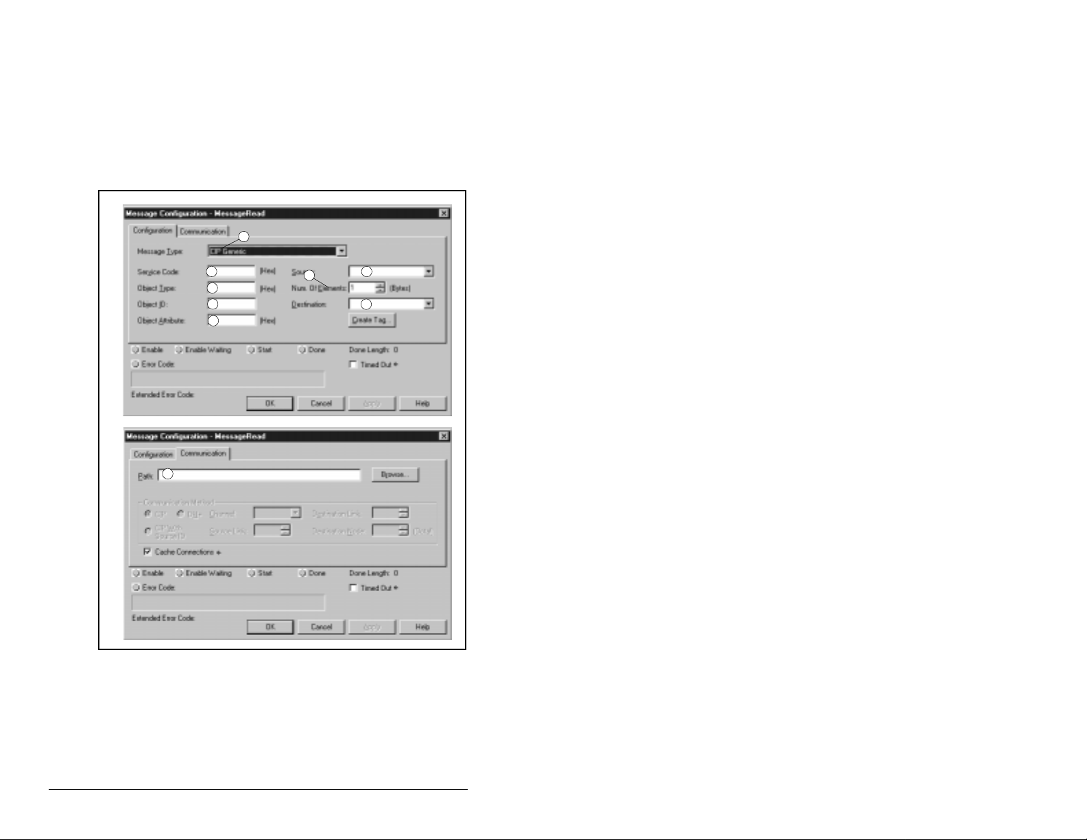
7.2 Formatting Explicit Messages for a
ControlLogix Controller
ControlLogix scanners accommodate both downloading Explicit
Message Requests and uploading Explicit Message Responses.
The scanner module c an accommodate on e request or res ponse f or
each transaction block. Each transaction block must be formatted
as shown in figure 7.1. Refer to table 7.1 for a description of the
data that is required in each box (items 1 – 9).
1
2
3
4
5
9
Figure 7.1 – ControlLogix Message Format in RSLogix 5000
7
6
8
7-2
To display the Message Configuration dialog box in RSLogix 5000,
add a message instruction, create a tag for the message
(properties: base tag, MESSAGE data type, controller scope), and
click the blue box inside the message.
When using a 1756-DNB scanner, five Explicit Messages can be
executed at a time.
DeviceNet Adapter for use with DPI AC Drives
Page 69

Table 7.1 – ControlLogix Message Requests and Responses
Box Description
Message Type
➀
The message type must be CIP Generic.
Service Code
➁
The service code is the requested DeviceNet service.
Available services depend on the class and instance
that you are using. Refer to Appendix C, DeviceNet
Objects.
Object Ty pe
➂
The object type is a DeviceNet class. Refer to
Appendix C, DeviceNet Objects, for available classes.
Object ID
➃
The object ID is an insta nce of a D e viceN et cla ss. R ef er
to Appendix C, DeviceNet Objects, for available
instances.
Object Attribute
➄
The object attrib ute is a clas s or instanc e attribute . Ref er
to Appendix C, DeviceNet Objects, for available classes.
Source
➅
This box contains the name of the tag for any service
data to be sent from the scanner to the adapter and
drive. A tag must be specified even if it is not used.
Num. of Elements
➆
This box contains the number of bytes of service data to
be sent or received in the mess age.
Destination
➇
This box contains the name of the tag that will receive
service response data from the adapte r and driv e. A tag
must be specified even if it is not used.
Path
➈
The path includes the following :
• Name of the DeviceNet scanner.
• Communication port on the front of the 1756-DNB
scanner. Always 2.
• Node address of the DeviceNet adapter. This is set
with switches or par amete rs in the De vi ceNet ada pter.
Click
adapter that you previously mapped.
Using Explicit Messaging
Browse
to find the path or type in the name of a
7-3
Page 70

7.3 Formatting Explicit Messages for a
PLC or SLC Controller
Transaction blocks in PLC and SLC scanners accommodate both
downloading Explicit Message Requests and uploading Explicit
Message Responses. The scanner module can accommodate one
request or response for each transaction block. Each transaction
block must be formatted as shown in figure 7.2 or figure 7.3.
Request Response
Bit 15 0 15 0
Word 0 TXID Command TXID Status
Port Size Port Size
Service Address Service Address
Class Service Response Data
Instance
Attribute
Word 6 - 31 Service Data
Word 32 TXID Command TXID Status
Port Size Port Size
Service Address Service Address
Class Service Response Data
Instance
Attribute
Word 38 - 63 Service Data
Figure 7.2 – PLC Explicit Message Format
7-4
Request Response
Bit 15 0 15 0
Word 0 TXID Command TXID Status
Port Size Port Size
Service Address Service Address
Class Service Response Data
Instance
Attribute
Word 6 - 31 Service Data
Figure 7.3 – SLC Explicit Message Format
Refer to tables 7.2 and 7.3 for a description of the data that is
required in each word.
DeviceNet Adapter for use with DPI AC Drives
Page 71

Table 7.2 identifies the number of transaction blocks within a
scanner that are reserved for Explicit Messaging.
Table 7.2 – Number of Transaction Blocks Reserved for Explicit Messaging
Scanner
No. of Transaction
Blocks
Words in Each
Transaction Block Refer To
1747-SDN 10 32 Figure 7.3
1771-SDN 10 32 (two blocks can
Figure 7.2
be moved at once)
Table 7.3 – PLC / SLC Explicit Message Requests
Word Description
Command
0
The Command is a code that instructs the scanner how to
administer the request during each download.
00 = Ignore transaction block (empty)
01 = Execute this transaction block
02 = Get status of transaction TXID
03 = Reset all client/server transactions
04 = Delete this transaction block (availabl e only for SLC)
05 – 255 = Reserved
TXID
The Transaction ID is a 1-byte integer between 1 and 255. It is
assigned in the ladder logic program when the processor creates
and downloads a request to the scanner. The scanner uses it to
track the transaction to completion. It returns this value with the
response that matches the request downloaded by the processor.
Size
1
The size of the service data is in bytes. Service data includes the
words for the class, instance, attribute, and any data. The
maximum size is 58 bytes (29 words).
Port
The port that is used by the message is always zero (Channel A)
on an SLC scanner. It is zero (Channel A) or one (Channel B) for a
PLC scanner.
Address
2
The node address of the slave device to which the transaction is
sent. For the Explicit Message to be successful, the slave device
must be in the scanlist of the scanner, and it must be online.
Service
Availab le services depend on the class and instance that you are
using.
Refer to Appendix C, DeviceNet Objects.
Class
3
Refer to Appendix C, DeviceNet Objects, f or available classes.
Instance
4
Refer to Appendix C, DeviceNet Objects, f or available instances.
Attribute
5
Refer to Appendix C, DeviceNet Objects, for available attributes.
Request
6 – 31
This is data used for the message. For example, it may be the
value written to a parameter.
(Least Significant Byte)
(Most Significant Byte)
(Least Significant Byte)
(Most Significant Byte)
(Least Significant Byte)
(Most Significant Byte)
Data
Using Explicit Messaging
7-5
Page 72

Table 7.4 – PLC / SLC Explicit Message Responses
Word Description
0
1
2
3 - 31
(Least Significant Byte)
Status
One of the following status codes is provided during each upload:
00 = Ignore transaction block (empty)
01 = Transaction completed successfully
02 = Transaction in progress (not ready)
03 = Slave not in scan list
04 = Slave offline
05 = DeviceNet port disabled or offline
06 = Transaction TXID unknown
08 = Invalid command code
09 = Scanner out of buffers
10 = Other client/server transaction in progress
11 = Could not connect to slave device
12 = Response data too large for block
13 = Invalid port
14 = Invalid size specified
15 = Connection busy
16 – 255 = Reserved
(Most Significant Byte)
TXID
The transaction ID is a 1-byte integer in word 31 with a range of 1 to
255. It is assigned in the ladder logic program when the processor
creates and downloads a request to the scanner. The scanner uses
it to track the transaction to completion. It returns this value with the
response that matches the request downloaded by the processor.
(Least Significant Byte)
Size
The size of the service data is in bytes. The service data includes
words used for the response data. The maximum size is 58 bytes
(29 words).
(Most Significant Byte)
Port
The port that is used by the message is always zero (Channel A) on
an SLC scanner. It is zero (Channel A) or one (Channel B) for a
PLC scanner.
Address
The node address of the slave device to which the transaction is
sent. For the Explicit Message to be successful, the slave device
must be in the scanlist of the scanner, and it must be online.
Service
If the message was successful, 0x80 is added to the service. If it is
unsuccessful, 0x94 is returned.
Response Data
This is data used for the message. For example, it ma y be the value
read from a parameter.
(Least Significant Byte)
(Most Significant Byte)
7-6
DeviceNet Adapter for use with DPI AC Drives
Page 73

7.4 Running Explicit Messages
There are five basic events in the Explicit Messaging process as
shown in figure 7 .4. The details of each st ep w i ll vary depending on
the controller (ControlLogix, PLC, or SLC). Refer to the
documentation for your controller.
Important:
➀
➁
➂
➃
➄
There must be a request message and an response
message for all Explicit Messages, whether you are
reading or writing data.
Set up and send Explicit
Message Request
5
Complete Explici t
Message
4
Retrieve Explicit
Message Response
You format the required data and set up the ladder logic
program to send an Expli cit Message req uest to the scan ner
module (download).
The scanner module transmits the Explicit Message
Request to the slave device over the DeviceNet network.
The slave device transmits the Explicit Message Response
back to the sca nne r. The d ata is st ored in the scanner b uffer.
The controller retrie v es the Explicit Messag e Respo nse from
the scanner’s buffer (upload).
The Explicit Message is complete. If you are using a PLC or
SLC, delete the transaction ID so that it can be reused.
2
3
1
Using Explicit Messaging
Figure 7.4 – Explicit Message Process
7-7
Page 74

7.5 ControlLogix Example
The data in this example is for an SP600 drive at node address 1.
Refer to section 7.2 for a description of the content in each box.
Configuration Value Description Refer to . . .
Service Code
Object Type
Object ID
Object Attribute
Figure 7.5 – Data Format for a Read and Write Parameter (1 of 2)
e (hex)
f (hex)
101 (dec)
1 (hex)
Get_Attribute_Single
Parameter Object
Par ameter Address
Parameter Value
Page C-10
Page C-8
Page C-9
7-8
DeviceNet Adapter for use with DPI AC Drives
Page 75

Configuration Value Description Refer to . . .
Service Code
Object Type
Object ID
Object Attribute
10 (hex)
f (hex)
101 (dec)
1 (hex)
Get_Attribute_Single
Parameter Object
Parameter Address
Parameter Value
Page C-10
Page C-8
Page C-9
Figure 7.6 – Data Format for a Read and Write Parameter (2 of 2)
Table 7.5 – Tags for the Sample Explicit Messaging Program
Ta g Names
for Read Message Type
Tag Names
for Write Messages Type
StartParameterRead BOOL StartParameterWrite BOOL
ParameterReadDestination INT ParameterWriteDestination INT
ParameterReadMessage MESSAGE ParameterWriteMessage MESSAGE
ParameterReadSource INT ParameterWriteSource INT
This rung reads the value of parameter 101. The value is in the ReadDes tination tag.
StartParameterRead
0
This rung writes the value of parameter 101. The value is taken from the WriteSource tag.
StartParameterWrite
1
Type - CIP Generic
Message Control ParameterReadMessage
Type - CIP Generic
Message Control ParameterWriteMessage
MSG
MSG
...
...
EN
DN
ER
EN
DN
ER
(End)
Figure 7.7 – Sample ControlLogix Ladder Logic Program
Using Explicit Messaging
7-9
Page 76

7.6 PLC-5 Example
Data Format for a Read and Write Parameter
The data in this example is for an SP600 drive at node address 1.
Refer to section 7.2 for a description of the content of the data file.
Table 7.6 – Request Data for Read of Drive Parameter 101
Address V alue (hex) Description Refer to . . .
N30:0 0101 TXID = 01, Command = 01 (execute) Section 7.3
N30:1 0006 Port = 00, Size = 06 bytes Section 7.3
N30:2 0E01 Service = 0E (Get_Attribute_Single) Page C-10
Address = 01 (Node Address) Section 7.3
N30:3 000F Class = 0F (Parameter Object) Page C-8
N30:4 0065 Instance = Parameter 101 (65 hex)
N30:5 0001 Attr ibute = 01 (Parameter Value) Page C-9
Table 7.7 – Response Data for Read of Drive Parameter 101
Address V alue (hex) Description Refer to . . .
N30:70 0101 TXID = 01, Status = 01 (successful) Section 7.3
N30:71 0002 Port = 00, Size = 02 bytes Section 7.3
N30:72 8E01 Service = 8E (successful),
Address = 01 (Node Address)
N30:73 03E8 Response Data = 1000 (3E8 hex) = 10.00
seconds
Section 7.3
Table 7.8 – Request Data for Write to Drive Parameter 101
Address Value (hex) Description Refer to . . .
N30:0 0101 TXID = 01, Command = 01 (execute) Section 7.3
N30:1 0008 Port = 00, Size = 08 bytes Section 7.3
N30:2 1001 Service = 10 (Set_Attribute_Single) Page C-10
Address = 01 (Node Address) Section 7.3
N30:3 000F Class = 0F (Parameter Object) Page C-8
N30:4 0065 Instance = Parameter 101 (65 hex)
N30:5 0001 Attribute = 01 (Parameter Value) Page C-9
N30:6 07D0 Data = 2000 (7D0 hex) = 20.00 seconds
Table 7.9 – Response Data for Write to Drive Parameter 101
Address V alue (hex) Description Refer to . . .
N30:70 0101 TXID = 01, Status = 01 (successfultransaction) Section 7.3
N30:71 0000 Port = 00, Size = 00 bytes Section 7.3
N30:72 9001 Service = 90 (successful)
7-10
Address = 01 (Node Address)
DeviceNet Adapter for use with DPI AC Drives
Section 7.3
Page 77

Ladder Logic Program
When I:000/17 is set to true, a one-time Block Tran sfer Write sends data to th e scanner . The Mov e
instruction then init ia lize s t he f irs t w ord of th e d ata fi le t hat is used by the Bloc k Transfer Read inst ructi on in
the next rung.
I:000
0000
When BT20:2.DN is true, the Block Transfer Write is complete. The
compare ins tr uction compar es the first word of data sent from the
scanner to th e fi rst w ord of d ata y ou se nd to t he sca nne r. When the
messaging function is comp lete, the tw o words are equal.
If the Block Transfer Read is not enabled, this instruction enables it
when BT20:2.DN and the compare are true. The Block Transfer
Read reads 64 words of dat a.
BT20:2
0001
DN
B3:0
ONS
17
0
CMP
Comparison
Expression N30:70 <> N30:0
Block Transfer Write
Module Type 1771-SDN DeviceNet Scanner Module
Rack 000
Group 0
Module 0
Control Block BT20:2
Data File N30:0
Length 64
Continuous No
BTW
Move
Source 0
Dest N30:70
BT20:3
EN
MOV
0<
257
EN
DN
ER
<
0002
Figure 7.8 – Sample PLC-5 Ladder Logic Program
Using Explicit Messaging
BTR
Block Transfer Read
Module Type 1771-SDN DeviceNet Scanner Module
Rack
Group
Module
Control Block
Data File
Length
Continuous
000
0
0
BT20:3
N30:70
64
No
END
EN
DN
ER
7-11
Page 78

7.7 SLC Example
Data Format for a Read and Write Parameter
The data in this example is for an SP600 drive at node address 1.
Refer to section 7.2 for a description of the content of the data file.
Table 7.10 – Request Data for Read of Drive Parameter 101
Address V alue (hex) Description Refer to . . .
N20:10 0101 TXID = 01, Command = 01 (execute) S ection 7.3
N20:11 0006 Port = 00, Size = 06 bytes Section 7.3
N20:12 0E01 Service = 0E (Get_Attribute_Single) Page C-10
Address = 01 (Node Address) Section 7.3
N20:13 000F Class = 0F (Parameter Object) Page C-8
N20:14 0065 Instance = Parameter 101 (65 hex)
N20:15 0001 Attribute = 01 (Parameter Value) Page C-10
Table 7.11 – Response Data for Read of Drive Parameter 101
Address V alue (hex) Description Refer to . . .
N20:50 0101 TXID = 01, Status = 01 (successful) Section 7.3
N20:51 0002 Port = 00, Size = 02 bytes Section 7.3
N20:52 8E01 Ser vice = 8E (successful)
Address = 01 (Node Address)
N20:53 03E8 Response Data = 1000 (3E8 hex) =
10.00 seconds
Section 7.3
Table 7.12 – Request Data for Write to Drive Parameter 101
Address V alue (hex) Description Refer to . . .
N20:10 0101 TXID = 01, Command = 01 (execute) S ection 7.3
N20:11 0008 Port = 00, Size = 08 bytes Section 7.3
N20:12 1001 Service = 10 (Set_Attribute_Single) Page C-10
Address = 01 (Node Address) Section 7.3
N20:13 000F Class = 0F (Parameter Object) Page C-8
N20:14 0065 Instance = Parameter 101 (65 hex)
N20:15 0001 Attribute = 01 (Parameter Value) Page C-9
N20:16 07D0 Data = 2000 (7D0 hex) = 20.00 seconds
Table 7.13 – Response Data for Write to Drive Parameter 101
Address V alue (hex) Description Refer to . . .
N20:50 0101 TXID = 01, Status = 01 (successful
N20:51 0000 Port = 00, Size = 00 bytes Section 7.3
N20:52 9001 Service = 90 (successful)
7-12
transaction)
Address = 01 (Node Address)
DeviceNet Adapter for use with DPI AC Drives
Section 7.3
Section 7.3
Page 79

Ladder Logic Program
Important:
T o origin ate a scanner tr ansaction, use a copy operation
to M0:[slot number]:224. Then, use a copy operation to
read M1:1.224 for the result. If more than one message
is enabled, use the TXID to determine which message
you are reading.
When B3:0/0 is set to true, this rung will
copy the 3 2 words of Explic it Message from
the buff er at N20:10 to M0-File Explicit
Message buffer. The scanner will send the
Initiate
message out over De viceNet.
Explicit
Message
0000
0001
B3:0
0
When I:1.0/15 is set to true and the Explicit
Message Response has been received in the
M1-File, this rung performs the following:
- Copies the response message into N10:50.
- Copies a command of four (4) into the
M1-File.The four (4) commands the 1747-SDN
scanner to discard the response data so th at the
buffe r can be used for the next message
response.
Explicit
Message
Response
Available
I:1.0
15
1747-SDN
Explicit
Message
COP
Copy File
Source
Dest
Length
Explicit
Message
Response
Copy File
Source #M1:1:224
Dest #N20:50
Length 32
#M0:1:224
COP
#N20:10
32
Initiate
Explicit
Message
B3: 0
U
0
0002
Figure 7.9 – Sample SLC Ladder Logic Program
Using Explicit Messaging
EQU
Equal
Source A N20:10
Source B N20:50
257 <
257 <
Explicit
Message
MVM
Mask Move
Source N20:0
Mask 00FFh
Dest M0:1.224
4<
255 <
?<
END
7-13
Page 80

7-14
DeviceNet Adapter for use with DPI AC Drives
Page 81

C
HAPTER
8
Troubleshooting the
DeviceNet Adapter
and Network
Chapter 8 contains information for troubleshooting the DeviceNet
adapter and network.
8.1 Understanding the Status Indicators
The DeviceNet adapter has three status indicators. They can be
viewed on the adapter or through the drive cover. See figure 8.1.
➀
➀
➁
➂
➁
➂
➃
Number
➀
➁
➂
➃
Sections 8.2 through 8.4 describe what the state of each status
indicator means. Note that if all status indicators are off, the
DeviceNet adapter is not receiving power. Refer to chapter 3,
Installing the DeviceNet Adapter, for installation instructions.
Troubleshooting the DeviceNet Adapter and Network
Status
Indicator Description Refe r to ...
DRIVE DPI Connection Status Section 8.1.1
MS Adapter Status Section 8.1.2
NET A DeviceNet Status Section 8.1.3
NET B Not Used for DeviceNet N/A
Figure 8.1 – Status Indicators (location on drive may vary)
8-1
Page 82

8.1.1 DRIVE Status Indicator
Table 8.1 – DRIVE Status Indicator: State Definitions
State Cause Corrective Action
Off The adapter is not
Flashing
Red
Solid
Red
Orange The adapter is
Flashing
Green
Solid
Green
powered or is not
connected properly to
the drive.
The adapter is not
receiving a ping
message from the
drive.
The drive has refused
an I/O connectio n from
the adapte r.
Another DPI peripheral
is using the same DPI
port as the adapter.
connected to a product
that does not support
Reliance Electric DPI
communications.
The adapter is
establishing an I/O
connection to the
drive.
The adapter is properly
connected and is
communicating with
the drive.
• Securely connect the
adapter to the drive using
the ribbon cable.
• Apply power to the drive.
• Verify that cables are
securely connected.
• Cycle power to the drive.
Important:
product after making an y of the
following corrections.
• Verify that all DPI cables on
the SP600 drive ar e securely
connected and not
damaged. Replace cables if
necessary.
• Verify that the SP600 drive
supports Datalinks.
• Configure the adapter and
SP600 drive to use a
Datalink that is not already
being used by another
peripheral.
• Connect the adapter to a
product that supports
Reliance Electric D PI
communications (for
example, SP600 driv es ).
• No action. This status
indicator will turn soli d gr een
or red.
• No action.
Cycle power to the
8-2
DeviceNet Adapter for use with DPI AC Drives
Page 83

8.1.2 MS Status Indicator
Table 8.2 – MS Status Indicator: State Definitions
State Cause Corrective Action
Off The adapter is not
Flashing
Red
Solid
Red
Flashing
Green
Solid
Green
powered.
The adapter has f a iled
the firmware test or
the node address
switch setting is
invalid.
The adapter has f a iled
the hardware test.
The adapter is
operational, but is not
transferring I/O data.
The adapter is
operational and
transferring I/O data.
• Securely connect the
adapter to the drive using the
ribbon cable.
• App ly power to the drive.
• Verify that the node address
switch setting is between 0
and 63.
• Clear faults in the adapter.
• Cyc le power to the drive.
• If cycling power does not
correct the problem, the
parameter settings may have
been corrupted. Reset
defaults and reconfigure the
adapter.
• If resetting defaults does not
correct the problem, flash the
adapter with the latest
firmware release.
• Cyc le power to the drive.
• Replace the adapter.
• Place the scanner in RUN
mode.
• Program the controller to
recognize an d transm it I/O to
the adapte r.
• Configure the adapter for the
program in the controller.
• No ac tion.
Troubleshooting the DeviceNet Adapter and Network
8-3
Page 84

8.1.3 NET A St at us In dicator
Table 8.3 – NET A Status Indicator: State Definitions
State Cause Corrective Actions
Off The adapter and/or
network is not pow ered
or adapter is not
connected properly to
the network.
Flashing
Red/
Green
Flashing
Red
Solid
Red
Flashing
Green
Solid
Green
The adapter has
received an Identify
Comm Fault request.
A DeviceNet I/O
connection has timed
out.
Failed duplicate node
detection test or bus
off.
The adapter is properly
connected but is not
communicating with
any devices on the
network.
The adapter is properly
connected and
communicating on the
network.
• Securely connect the adapter
to the drive using the Internal
Interface cable and to the
network using a DeviceNet
cable.
• Correctly connect the
DeviceNet cable to the
DeviceNet plug.
• Apply power to the drive and
network.
• Wait for the faulted node
recovery to complete.
• Place the scanner in RUN
mode, or apply power to the
peer device that will send I/O.
• Check the amount of tr affic on
the network.
• Configure the adapter to use
a unique node add ress on the
DeviceNet network.
• Configure the adapter to use
the correct network data rate.
• Ensure network has correct
media installed.
• Place the controller in RUN
mode, or apply power to the
peer device that will send I/O.
• Program a control ler or peer
device to recognize and
transmit I/O to the adapter.
• Configure the adapter for the
program in the controller or
the I/O from the peer device.
• No action required.
8-4
DeviceNet Adapter for use with DPI AC Drives
Page 85

8.2 Adapter Diagnostic Items
The following diagnostic items can be accessed using VS Utilities.
Table 8.4 – Diagnostic Items Accessed Using VS Utilities
No. Name Description
1 Common Logic
Cmd
2 Prod Logic Cmd Current value of the Product Spec ific L ogic Comm and
3 Reference Current value of the Product Specific Reference being
4 Common Logic
Sts
5 Prod Logic Sts Current value of the Product Specific Logic Status
6 Feedback Current v alue of the Product Specifi c Feedbac k b ein g
7 Datalink A1 In Current value of Datalink A1 In being transmitted to
Current value of the Common Logic Command being
transmitted to the host by this peripheral.
being transmitted to the host by this peripheral.
transmitted to the host by this peripheral.
Current value of the Common Logic Status being
received from the host by this peripheral.
being received from the host by this peri pheral.
received from the host by this peripheral.
the host by this peripheral (if not using Datalink A1,
this parameter should have a value of zero).
8 Datalink A2 In Current value of Datalink A2 In being transmitted to
the host by this peripheral (if not using Datalink A2,
this parameter should have a value of zero).
9 Datalink B1 In Current value of Datalink B1 In being transmitted to
the host by this peripheral (if not using Datalink B1,
this parameter should have a value of zero).
10 Datalink B2 In Current value of Datalink B2 In being transmitted to
the host by this peripheral (if not using Datalink B2,
this parameter should have a value of zero).
11 Datalink C1 In Current value of Datalink C1 In being transmitted to
the host by this peripheral (if not using Datalink C1,
this parameter should have a value of zero).
12 Datalink C2 In Current value of Datalink C2 In being transmitted to
the host by this peripheral (if not using Datalink C2,
this parameter should have a value of zero).
13 Datalink D1 In Current value of Datalink D1 In being transmitted to
the host by this peripheral (if not using Datalink D1,
this parameter should have a value of zero).
14 Datalink D2 In Current value of Datalink D2 In being transmitted to
the host by this peripheral (if not using Datalink D2,
this parameter should have a value of zero).
Troubleshooting the DeviceNet Adapter and Network
8-5
Page 86

Table 8.4 – Diagnostic Items Accessed Using VS Utilities (Continued)
No. Name Description
15 Datalink A1 Out Current value of Datalink A1 being received from the
host by this peripheral.
16 Datalink A2 Out Current value of Datalink A2 being received from the
host by this peripheral.
17 Datalink B1 Out Current value of Datalink B1 being received from the
host by this peripheral.
18 Datalink B2 Out Current value of Datalink B2 being received from the
host by this peripheral.
19 Datalink C1 Out Current value of Datalink C1 being received from the
host by this peripheral.
20 Datalink C2 Out Current value of Datalink C2 being received from the
host by this peripheral.
21 Datalink D1 Out Current value of Datalink D1 being received from the
host by this peripheral.
22 Datalink D2 Out Current value of Datalink D2 being received from the
host by this peripheral.
23 Field Flash Cntr Current value of the Field Flash Counter.
24 DPI Rx Errors Current value of the DPI CAN Transmit Error Counter
register.
25 DPI Tx Errors Maximum value of the DPI CAN Transmit Error
Counter register.
26 DNet Rx Errors Current value of the DNet CAN Re ceive Erro r Counter
register .
27 DNet Tx Errors Maximum value of the DNet CAN Receive Error
Counter register.
8-6
DeviceNet Adapter for use with DPI AC Drives
Page 87

8.3 Viewing and Clearing Events
The adapter mainta in s a n event q ueu e t hat reports the history of its
actions. You can view the event queue using an LCD OIM or
VS Utilities software.
To View and Clear Events Using an LCD OIM
Use the procedure shown in figure 8.2 to access the Event Queue
using the LCD OIM. Note that you must have the RECOMM-DNET
adapter as the selected device to access the event queue.
!!
6WRSSHG $XWR
3 5(&200'1(7
0DLQ 0HQX
'LDJQRVWLFV
0RQLWRU
+LJKOLJKW 'LDJQRVWLFV LFRQ
Figure 8.2 – VIewing and Clearing Events Using an LCD OIM
/DQJ
Events
Many events in the Event queue occur under normal operation. If
you encounter unexpected communications problems, the events
may help you or Reliance Electric personnel troubleshoot the
problem. Table 8.5 lists events that may appear in the event queue.
Table 8.5 – Event Codes and Descriptions
'LDJQRVWLFV
9LHZ (YHQW 4XHXH
'HYLFH 9HUVLRQ
2,0 9HUVLRQ
+LJKOLJKW LWHP
(YW4 ( [[[[[
2QOLQH # NESV
3UHVV ) NH\ WR
FOHDU HYHQW TXHXH
&OUTX
Code Event Description
0 No Event Empty event queue entry.
1 DPI Bus Off Flt A bus off condition was detected on DPI. This event
may be caused by loose or broken cables or by
noise.
2 Ping Time Flt A ping message was not received on DPI within the
specified time.
3 Port ID Flt The adapter is not connected to a correct port on a
DPI product.
4 Port Change
The DPI port changed.
Flt
5 Host Sent
The DPI product issued this because it was reset.
Reset
Troubleshooting the DeviceNet Adapter and Network
8-7
Page 88

Table 8.5 – Event Codes and Descriptions (Continued)
Code Event Description
6 EEPROM
The EEPROM in the adapter is corrupt.
Sum Flt
7Online @
125 kbps
8Online @
500 kbps
The adapter and DPI product are communicating at
125 kbps.
The adapter and DPI product are communicating at
500 kbps.
9 Bad Host Flt The adapter was connected to an incompatible
product.
10 Dup. Port Flt Another peripheral with the same port number is
already in use.
11 Type 0 Login The adapter has logged in for type 0 control.
12 Type 0 Time
Flt
The adapter has not received a type 0 status
message within the specified time.
13 DL Login The adapter has logged into a Datalink.
14 DL Reject Flt The host rejected an attempt to log in to a Datalink
because the Datalink is not supported or is used by
another peripheral.
15 DL Time Flt The adapter has not received a Datalink message
within the specified time.
16 Control
Disabled
17 Control
Enabled
18 PCCC IO Time
Flt
19 Normal
The adapter has sent a “Soft Control Disable”
command to the DPI product.
The adapter has sent a “Soft Control Enable”
command to the DPI product.
The adapter has not received a PCCC control
message within the specified time-out interval.
The adapter successfully started up.
Startup
20 Message
Timeout
A client-server message sent by the peripheral was
not completed.
21 DPI Fault Msg The DPI Host has faulted.
22 DN Poll
Timeout
23 DN I/O Too
Long
24 Bad I/O
Fragment
8-8
A polled I/O connection has timed out.
Reconfigure the I/O length in the scanner.
A DeviceNet I/O fragment was received out of
sequence. Possible line noise problem.
DeviceNet Adapter for use with DPI AC Drives
Page 89

Table 8.5 – Event Codes and Descriptions (Continued)
Code Event Description
25 Idle I/O
Message
The DeviceNet scanner was placed in program
mode.
26 Peer I/O
Timeout
27 DPI Fault
Clear
28 DN COS
Timeout
29 DN Poll
Allocate
30 DN COS
Allocate
31 DN Poll
Closed
32 DN COS
Closed
33 Safe State
Error
34 Language
CRC Bad
The adapter has not received peer I/O from another
device on the network within the specified time-out
interval.
The DPI product issued this because a fault was
cleared.
A change of state (COS) connection has timed out.
A polled connection has been allocated.
A change of state (COS) I/O connection has been
allocated.
A polled I/O connection was explicitly closed.
A change of state (COS) connection was explicitly
closed.
At least one of the Fault Configuration parameters
contains a value greater than 65535 and the DPI
product expects a 16-bit value.
The language text memory segment is corrupt.
Troubleshooting the DeviceNet Adapter and Network
8-9
Page 90

8-10
DeviceNet Adapter for use with DPI AC Drives
Page 91

A
PPENDIX
Technical
Specifications
Communications
Network
Protocol
Data Rates
Electrical
Consumption 150 mA at +5 V supplied through the drive
DeviceNet
125K, 250K, 500K, Autobaud, PGM
The PGM (Program) setting on the switch is
used to set the data rate using the adapter
parameter. Autobaud can be set only if
another device on the network is setting a
data rate.
60 mA at +24 V supplied through DeviceNet
Use the 60 mA value to size the network
current draw from the power supply.
A
Mechanical
Dimensions
Height
Length
Width
Weight 85 g (3 oz)
Environmental
Temperature
Operating
Storage
Relative Humidity 5 to 95% non-condensing
Regulatory Compliance
UL 508C and CUL
CE EN61800-3
Technical Specifications
19 mm (0.75 in)
86 mm (3.33 in)
78.5 mm (3.09 in)
-10 to +50°C (14 to 149°F)
-40 to +85°C (-40 to 185°F)
A-1
Page 92

A-2
DeviceNet Adapter for use with DPI AC Drives
Page 93

A
PPENDIX
B
DeviceNet Adapter
Parameters
The following information is provided for each DeviceNet adapter
parameter along with its description:
Parameter Number: Unique number assigned to each
Parameter Name: Unique name assigned to each
Range: Predefined parameter limits or
Default: Factory default setting.
Type: Read Only or Read/Write
Reset Required: Adapter must be re set before p arameter
The parameters in the DeviceNet adapter are numbered
sequentially. However, depending on the configuration tool used,
they may have different numbers.
parameter.
parameter.
selections.
value is recognized.
DeviceNet Adapter Parameters
B-1
Page 94

1DPI Port
Range:
Default:
Type:
Reset Required:
Port to which the adapter is connected. This will usually be port 5.
0 to 7
0
Read Only
N/A
2 DPI Data Rate
Range:
Default:
Type:
Reset Required:
Data rate used b y th e driv e . Th is data rate is se t in the driv e a nd the
adapter det ects it.
0 = 125 kbps
1 = 500 kbps
1 = 500 kbps
Read Only
N/A
3 DN Addr Cfg
Range:
Default:
Type:
Reset Required:
Node address if the Data Rate switch is set to “PGM” (Program).
0 to 63
63
Read/Write
Yes
4 DN Addr Actual
Range:
Default:
Type:
Reset Required:
DeviceNet node address actually used by the adapter.
B-2
0 to 63
63
Read Only
N/A
DeviceNet Adapter for use with DPI AC Drives
Page 95

5 DN Rate Cfg
Range:
Default:
Type:
Reset Required:
DeviceNet data rate if the data rate switch is set to “PGM”
(Program).
0 = 125 kbps
1 = 250 kbps
2 = 500 kbps
3 = Autobaud
3 = Autobaud
Read/Write
Yes
6 DN Rate Actual
Range:
Default:
Type:
Reset Required:
DeviceNet data rate actually used by the adapter.
0 = 125 kpbs
1 = 250 kbps
2 = 500 kbps
3 = Autobaud
0 = 125 kbps
Read Only
N/A
7 Ref/Fdbk Size
Range:
Default:
Type:
Reset Required:
0 = 16-bit
1 = 32-bit
0 = 16-bit
Read Only
N/A
Size of the Reference/Feedback. The drive determines the size of
the Reference/Feedback.
8 Datalink Size
Range:
Default:
Type:
Reset Required:
Size of each Datalink word. The drive determines the size of
Datalinks.
DeviceNet Adapter Parameters
0 = 16-bit
1 = 32-bit
0 = 16-bit
Read Only
N/A
B-3
Page 96

9 Reset Module
Range:
Default:
Type:
Reset Required:
This parameter is a com m and . It wil l b e re set to 0 = Ready after th e
command has been performed.
0 = Ready (No action)
1 = Reset Modu le
2 = Set Defaults (Restores adapter to factory-default
settings)
0 = Ready
Read/Write
No
ATTENTION:
controls the drive , the drive may f ault when you reset
!
the adapter . De termine ho w y our driv e will res pond
before resetting a connected adapter. Failure to
observe this precaution c oul d res ult in bodily injury
or damage to equipment.
If the adapter is transmitting I/O that
10 Comm Flt Action
Range:
Default:
Type:
Reset Required:
Action that the adapter and drive take if the adapter detects that
DeviceNet communications have been disrupted. This setting is
effective only if I/O that controls the drive is transmitted though the
adapter.
0 = Fault
1 = Stop
2 = Zero Data
3 = Hold Last
4 = Send Flt Cfg
0 = Fault
Read/Write
ATTENTION:
determine the action the adapter and connected
!
drive if communications are disrupted. By default,
this parameter faults the drive. You can set this
parameter so that the drive continues to run. Take
precautions to ensure that the setting of this
parameter does not create a hazard of injury or
equipment damage. Failure to observe this
precaution could result in bodily inj ury or damage to
equipment.
No
Comm Flt Action (10) lets you
B-4
DeviceNet Adapter for use with DPI AC Drives
Page 97

11 Idle Flt Action
Range:
Default:
Type:
Reset Required:
Sets the action that the adapter and the drive take if the adapter
detects that th e sc ann er is idle becaus e th e con t rol ler was swi tc hed
to program mo de. Thi s setting is eff ectiv e on ly if the I/O that con trols
the drive is transmitted through the adapter.
0 = Fault
1 = Stop
2 = Zero Data
3 = Hold Last
4 = Send Flt Cfg
0 = Fault
Read/Write
No
ATTENTION:
the action of th e ada pter and connected d rive if the
!
scanner is idle. By def au lt, this para meter f aults the
drive. Y ou can set this so that the drive continues to
run. Ensure that the setting of this parameter does
not create a haza rd of inju ry or equipmen t damage .
Failure to observe this precaution could result in
bodily injury or damage to equipment.
Idle Flt Action (11) lets you determine
12 DN Active Cfg
Range:
Default:
Type:
Reset Required:
Source from which the adapter node address and data rate are
taken. This will either be switches or parameters in EEPROM. It is
determined by the settings of the switches on the adapter.
0 = EEPROM
1 = Switches
1 = Switches
Read Only
N/A
DeviceNet Adapter Parameters
B-5
Page 98

13 DPI I/O Config
Range:
Default:
Type:
Reset Required:
I/O that is transferred.
See figure B.1.
See figure B.1.
Read Only
N/A
Not Used
Not Used
Not Used
Figure B.1 – DPI I/O Config (13)
Datalink C
Datalink D
Datalink B
00010xxx
Datalink A
Cmd/Ref
01234567
1= I/O Enabled
0= I/O Disabled
x=Not Used
14 DPI I/O Active
Range:
Default:
Type:
Reset Required:
I/O that the adapter is actively transmitting. The value of this
parameter will usually be equal to the value of DPI I/O Config (13).
See figure B.2.
See figure B.2.
Read Only
N/A
B-6
1= I/O Enabled
Cmd/Ref
01234567
0= I/O Disabled
x=Not Used
Datalink C
Datalink D
Not Used
Not Used
Not Used
Figure B.2 – DPI I/O Active (14)
Datalink A
Datalink B
00010xxx
DeviceNet Adapter for use with DPI AC Drives
Page 99

15 Flt Cfg Logic
Range:
Default:
Type:
Reset Required:
Sets the Logic Command data that is sent to the drive if the
following is true:
• Comm Flt Action (10) is set to Send Flt Cfg and communications
are disr upted.
• Idle Flt Action (11) is set to Send Flt Cfg and the scanner is put
into Program or Test mode.
• Peer Flt Action (34) is set to Fault Cfg and communications are
disrupted.
The bit definitions will depen d on the prod uct to whi ch the adap ter is
connected.
0000 0000 0000 0000 to 1111 1111 1111 1111
0000 0000 0000 0000
Read/Write
No
16 Flt Cfg Ref
Range:
Default:
Type:
Reset Required:
0 to 4294967295
0
Read/Write
No
Sets the Reference data that is sent to the drive if any of the
following is true:
• Comm Flt Action (10) is set to Send Flt Cfg and communications
are disr upted.
• Idle Flt Action (11) is set to Send Flt Cfg and the scanner is put
into Program mode.
• Peer Flt Action (34) is set to Fault Cfg and the scanner is put into
Program mode.
• Peer Flt Action (34) is set to Fault Cfg and communications are
disrupted.
Important: If the drive uses a 16-bit Refer ence , the mos t sign ificant
word of this value must be set to zero (0) or a fault will
occur.
DeviceNet Adapter Parameters
B-7
Page 100

Flt Cfg A1
17
Flt Cfg A2
18
Flt Cfg B1
19
Flt Cfg B2
20
Flt Cfg C1
21
Flt Cfg C2
22
Flt Cfg D1
23
Flt Cfg D2
24
Range:
Default:
Type:
Reset Required:
0 to 4294967295
0
Read/Write
No
Sets the data that is sent to the Datalink in the drive if any of the
following is true:
• Idle Flt Action (11) is set to Send Flt Cfg and the scanner is put
into Program mode.
• Comm Flt Action (10) is set to Send Flt Cfg and communications
are disr upted.
• Peer Flt Action (34) is set to Fault Cfg and communications are
disrupted.
25 M-S Input
Range:
Default:
Type:
Reset Required:
0 = I/O Disabled
1 = I/O Enabled
See figure B.3.
Read/Write
Yes
B-8
Master-slave input data. This data is produced by the scanner and
consumed by the adapter.
1=I/O Enabled
Cmd/Ref
01234567
0=I/O Disabled
x=Not Used
DL C Input
DL D Input
Not Used
Not Used
Not Used
Figure B.3 – M-S Input (25)
DL A Input
DL B Input
00010xxx
DeviceNet Adapter for use with DPI AC Drives
 Loading...