

Page 1

ControlNet
Communications Module
M/N RECOMM-CNET
Instruction Manual
D2-3497
Page 2
The information in this manual is subject to change without notice.
Trademarks not belonging to Rockwell Automation are
property of their respective companies.
Throughout this manual, the following notes are used to alert you to safety
considerations:
ATTENTION:
circumstances that can lead to personal injury or death, property
damage, or economic loss.
Identifies information about practices or
!
Important: Identifies information that is critical for successful application and
understanding of the product.
ATTENTION:
injury or death. Remove all power from the drive, and then verify
power has been removed before installing or removing a
!
This product has been self-tested by the manufacturer and found to comply with
ControlNet International Conformance Test Software Version 12.
Windows, Windows NT, and Microsoft are trademarks of Microsoft Corporation.
ControlNet is a trademark of ControlNet International, Ltd.
Reliance, SP600, VS Utilities, DPI, RSLogix, ControlLogix, and SLC are
trademarks of Rockwell Automation.
©2001 Rockwell Automation. All rights reserved.
ControlNet module. Failure to observe these precautions could
result in severe bodily injury or loss of life.
ATTENTION:
drive and power products and the associated machinery should
plan or implement the installation, start up, configuration, and
subsequent maintenance of the product using a ControlNet
module. Read and understand this manual in its entirety before
proceeding. Failure to observe these precautions could result
bodily injury and/or damage to equipment.
ATTENTION:
together via RECBL-xxx cables. Unpredictable behavior due to
timing and other internal procedures can result if two or more
devices are connected in this manner. Failure to observe this
precaution could result bodily injur y and/or damage to equipment.
ATTENTION:
I/O to the drive, the drive may fault when you reset the module.
Determine how your drive will respond before resetting an module.
Failure to observe this precaution could result bodily injury
and/or damage to equipment.
ATTENTION:
you determine the action of the module and connected drive if
communications are disrupted. By default, these parameters fault
the drive. You can set these parameter s so that the drive continues
to run. Precautions should be taken to ensure that the settings of
these parameters do not create a hazard of injury or equipment
damage. Failure to observe this precaution could result bodily
injury and/or damage to equipment.
ATTENTION:
may be unintended or incorrect machine motion. Disconnect the
motor from the machine or process during initial system testing.
Failure to observe this precaution could result bodily injury
and/or damage to equipment.
The drive may contain high voltages that can cause
Only qualified electrical personnel familiar with
DPI host products must not be directly connected
If the ControlNet module is transmitting control
Comm Flt Action (10) and Idle Flt Action (11) let
When a system is configured for the first time, there
Page 3

C
ONTENTS
Chapter 1 Introduction
1.1 ControlNet Module Features.......................................... 1-1
1.2 Related Documentation................................................. 1-2
1.3 Conventions Used in This Manual................................. 1-2
1.4 Getting Assistance from Reliance Electric..................... 1-2
Chapter 2 Getting Started
2.1 ControlNet Module Components ................................... 2-1
2.2 Required Equipment...................................................... 2-2
2.3 Installation Checklist...................................................... 2-3
Chapter 3 Installing the ControlNet Module
3.1 Preparing for an Installation........................................... 3-1
3.2 Commissioning the Module ........................................... 3-1
3.3 Connecting the Module to the Drive .............................. 3-2
3.4 Connecting the Module to the Network.......................... 3-5
3.5 Applying Power.............................................................. 3-6
Chapter 4 Configuring the ControlNet Module
4.1 Configuration Tools........................................................ 4-1
4.2 Using the LCD OIM to Configure the Module................ 4-2
4.3 Setting the Node Address.............................................. 4-2
4.4 Setting the I/O Configuration ......................................... 4-3
4.5 Selecting Master-Slave.................................................. 4-4
4.6 Selecting Reference Adjust ........................................... 4-5
4.7 Setting a Fault Action..................................................... 4-5
4.7.1 Changing the Fault Action ................................... 4-6
4.7.2 Setting the Fault Configuration Parameters ........ 4-7
4.7.3 Resetting the Module........................................... 4-7
4.8 Viewing the Module Configuration................................. 4-8
Chapter 5 RSNetWorx Configuration for PLC-5C Applications
5.1 Configuring a ControlNet Network: An Example............ 5-1
5.1.1 Installing and Registering EDS Files in
RSNetWorx ......................................................... 5-2
5.1.2 Configuring a Network with RSNetWorx.............. 5-7
5.1.3 Verifying Network Properties............................. 5-18
Contents
I
Page 4

Chapter 6 PLC-5C Applications
6.1 About I/O Messaging .....................................................6-1
6.2 Understanding the I/O Image......................................... 6-2
6.3 Using Logic Command/Status .......................................6-4
6.4 Using Reference/Feedback ...........................................6-5
6.5 Using Datalinks..............................................................6-5
6.5.1 Rules for Using Datalinks ....................................6-5
6.5.2 32-Bit Parameters using 16-Bit Datalinks............ 6-6
6.6 Function of the Sample Program ................................... 6-7
6.7 Main Program (PLC-5C) ................................................ 6-8
6.8 About Explicit Messaging............................................. 6-12
6.8.1 Performing Explicit Messages ...........................6-12
6.8.2 Explicit Messaging Examples ............................ 6-13
Chapter 7 ControlLogix Applications
7.1 Configuring a ControlLogix CNB Scanner ..................... 7-2
7.2 Function of the Sample Program ................................. 7-15
7.3 RSLogix 5000 Ladder Logic Program.......................... 7-17
7.4 About Explicit Messaging............................................. 7-19
7.4.1 Performing Explicit Messages ...........................7-19
7.4.2 Explicit Messaging Examples ............................ 7-20
Chapter 8 Troubleshooting the ControlNet Module and Network
8.1 Understanding the Status Indicators.............................. 8-1
8.1.1 DRIVE Status Indicator........................................ 8-2
8.1.2 MS Status Indicator ............................................. 8-3
8.1.3 NET A and B Together ........................................ 8-4
8.1.4 NET A and B Independently ................................ 8-5
8.2 Module Diagnostic Items................................................8-6
8.3 Viewing and Clearing Events.........................................8-8
Appendix A
Appendix B
Appendix C
Appendix D
Glossary
Index
II
Technical Specifications...................................................... A-1
ControlNet Module Parameters............................................ B-1
ControlNet Objects............................................................... C-1
Logic Command/Status Words............................................. D-1
..................................................................................Glossary-1
.......................................................................................Index-1
ControlNet Communications Module
Page 5

List of Figures
Figure 2.1 – Components of the ControlNet Module .................................. 2-1
Figure 3.1 – Setting the Module’s Node Address ....................................... 3-2
Figure 3.2 – DPI Ports and Internal Interface Cables................................. 3-3
Figure 3.3 – Mounting the Module.............................................................. 3-4
Figure 3.4 – Typical ControlNet Network Wiring......................................... 3-5
Figure 4.1 – Accessing the ControlNet Parameters using the LCD OIM.... 4-2
Figure 4.2 – ControlNet Node Address Screen on an LCD OIM ................ 4-2
Figure 4.3 – I/O Configuration Screen on an LCD OIM .............................. 4-3
Figure 4.4 – Master-Slave Input Screen on an LCD OIM........................... 4-4
Figure 4.5 – Master-Slave Input Screen on an LCD OIM........................... 4-4
Figure 4.6 – Fault Action Screens on an LCD OIM..................................... 4-6
Figure 4.7 – Reset Screen on an LCD OIM................................................ 4-8
Figure 5.1 – Sample ControlNet Network ................................................... 5-1
Figure 5.2 – Rockwell Software EDS Wizard.............................................. 5-2
Figure 5.3 – EDS Wizard Option Screen.................................................... 5-3
Figure 5.4 – EDS Wizard Designation Screen............................................ 5-3
Figure 5.5 – EDS Files Installation Test Results Screen ............................ 5-4
Figure 5.6 – EDS Wizard Change Graphic Image Screen.......................... 5-5
Figure 5.7 – EDS Wizard Final Task Summary Screen.............................. 5-6
Figure 5.8 – EDS Wizard Completion Screen............................................. 5-6
Figure 5.9 – RSNetWorx for ControlNet DPI to ControlNet Folder
Example.................................................................................. 5-7
Figure 5.10 – RSNetWorx for ControlNet Screen....................................... 5-8
Figure 5.11 – Sample Browse for Network Dialog Box............................... 5-9
Figure 5.12 – Sample Network Displayed in RSNetWorx........................... 5-9
Figure 5.13 – Sample ControlNet Configuration Screen........................... 5-10
Figure 5.14 – Sample ControlNet Configuration Box................................ 5-11
Figure 5.15 – Example of Product Line after Drive Connection is
Selected ............................................................................. 5-11
Figure 5.16 – Online / Offline Mismatch Dialog Box ................................. 5-12
Figure 5.17 – Save Data Screen.............................................................. 5-12
Figure 5.18 – Scanlist Configuration Screen ........................................... 5-13
Figure 5.19 – Integer Files for ControlNet Communications Screen ........ 5-14
Figure 5.20 – Communicaiton Properties ................................................. 5-15
Figure 5.21 – Connection Properties: Electronic Keying Settings ............ 5-16
Figure 5.22 – Connection Properties: Details Settings ............................. 5-16
Figure 5.23 – ScanList Configuration: Mapped Nodes ............................. 5-17
Figure 5.24 – Save Configuration Dialog Box........................................... 5-17
Figure 5.25 – Save As File Box ................................................................ 5-18
Figure 5.26 – ControlNet Dialog Box ........................................................ 5-19
Figure 5.27 – ControlNet: Media Configuration Tab ................................. 5-19
Figure 5.28 – ControlNet: General Tab..................................................... 5-20
Contents
III
Page 6

Figure 6.1 – Sample I/O Image with All I/O Enabled................................... 6-3
Figure 6.2 – Sample I/O Image with Only Logic/Reference and
Datalink B Enabled .................................................................6-4
Figure 6.3 – I/O Messaging......................................................................... 6-8
Figure 6.4 – I/O Messaging (Continued).....................................................6-9
Figure 6.5 – I/O Messaging (Continued)...................................................6-10
Figure 6.6 – I/O Messaging (Continued)...................................................6-11
Figure 6.7 – Explicit Message Process.....................................................6-12
Figure 6.8 – Explicit Messaging................................................................ 6-13
Figure 6.9 – CIO Get Attributes Scattered Screen.................................... 6-14
Figure 6.10 – CIO Set Attributes Scattered Screen..................................6-15
Figure 6.11 – CIO Get Attribute Single Screen.........................................6-17
Figure 6.12 – CIO Set Attribute Single Screen ......................................... 6-18
Figure 7.1 – RSLogix 5000: I/O Configuration Selection ............................7-2
Figure 7.2 – RSLogix 5000: New Module Selection.................................... 7-3
Figure 7.3 – Select Module Type: 1756-CNB/B Selection .......................... 7-3
Figure 7.4 – Module Properties: Name Selection .......................................7-4
Figure 7.5 – Module Properties: Controller-to-Module Behavior Screen .... 7-4
Figure 7.6 – Module Properties: Indentification/Status Screen................... 7-5
Figure 7.7 – Module Properties: Informational Screen................................ 7-5
Figure 7.8 – RSLogix 5000: I/O Configuration Folder.................................7-6
Figure 7.9 – RSLogix 5000: New Module Selection Screen ....................... 7-7
Figure 7.10 – Select Module Type: Generic ControlNet Module Screen.... 7-8
Figure 7.11 – Module Properties: ControlNet Module Parameters............. 7-9
Figure 7.12 – Module Properties: RPI Selection......................................... 7-9
Figure 7.13 – Module Properties: My ControlNet...................................... 7-10
Figure 7.14 – RSLogix: Configure Additional Nodes Screen .................... 7-10
Figure 7.15 – RSLogix 5000: Module-Defined Screen.............................. 7-11
Figure 7.16 – Download to the Controller Dialong Box............................. 7-11
Figure 7.17 – RSLogix: Attention Symbol.................................................7-12
Figure 7.18 – RSNetWorx for ControlNet Screen..................................... 7-13
Figure 7.19 – RSLogix 5000: Example Without Attention Symbol............ 7-14
Figure 7.20 – RSLogix 5000: Connection Tree Without Attention Symbol7-15
Figure 7.21 – I/O Messaging..................................................................... 7-17
Figure 7.22 – I/O Messaging (Continued).................................................7-18
Figure 7.23 – Explicit Message Process...................................................7-19
Figure 7.24 – Explicit Messaging .............................................................. 7-20
Figure 7.25 – Get_Attributes_Scattered Message Screen........................7-21
Figure 7.26 – Set_Attributes_Scattered Message Screen........................7-22
Figure 7.27 – Set_Attribute_Single Message Screen ............................... 7-24
Figure 7.28 – Get_Attributes_Single Message Screen.............................7-25
Figure 8.1 – Status Indicators (Location on Drive May Vary)...................... 8-1
Figure 8.2 – VIewing and Clearing Events Using an LCD OIM...................8-8
IV
ControlNet Communications Module
Page 7

List of Tables
Table 2.1 – Equipment Shipped with the ControlNet Module................... 2-2
Table 2.2 – Required User-Supplied Equipment ...................................... 2-2
Table 4.1 – Configuration Tools................................................................ 4-1
Table 4.2 – Selections for Drive Response to Communication Fault........ 4-6
Table 4.3 – Fault Configuration Parameters............................................. 4-7
Table 4.4 – Module Configuration Status Parameters.............................. 4-8
Table 5.1 – Input/Output Table............................................................... 5-14
Table 6.1 – Parameter Settings for the Sample Program......................... 6-7
Table 7.1 – Parameter Settings for the Sample Program....................... 7-16
Table 8.1 – DRIVE Status Indicator: State Definitions.............................. 8-2
Table 8.2 – MS Status Indicator: State Definitions ...................................8-3
Table 8.3 – NET A and B Together: State Definitions .............................. 8-4
Table 8.4 – NET A and B Independently: State Definitions ...................... 8-5
Table 8.5 – Module Diagnostic Items........................................................ 8-6
Table 8.6 – Event Codes and Descriptions............................................... 8-8
Contents
V
Page 8

VI
ControlNet Communications Module
Page 9

C
HAPTER
Introduction
The ControlNet module (RECOMM-CNET) is an embedded
communication option for DPI AC drives, such as the SP600
drive. The module is mounted in the drive and receives its required
power from the drive and from the network.
The module can be used with other products that implement DPI, a
peripheral communication interface. Refer to the documentation for
your product for specific information about how it works with the
module.
This manual is intended for qualified electrical personnel familiar
with installing, programming, and maintaining AC drives and
networks.
1.1 ControlNet Module Features
The ControlNet module features the following:
A number of configuration tools that can be used to configure the
•
module and connected drive. The tools include the LCD Operator
Interface Module (OIM) on the drive and drive-configuration
software such as VS Utilities (version 1.01 or later)
Status indicators that report the status of the drive
•
communications, module, and network. They are visible both
when the cover is opened and when it is closed.
I/O, including Logic Command/Reference and up to four pairs of
•
Datalinks, that may be configured for your application using a
parameter.
Support of explicit messages.
•
User-defined fault actions that determine how the module and the
•
drive respond to communication disruptions on the network and
controllers in idle mode.
1
.
Introduction
1-1
Page 10

1.2 Related Documentation
Refer to the following related publications as necessary for more
information. All of the publications are available from
http://www.theautomationbookstore.com.
D2-3485 SP600 AC Drive User Manual
•
D2-3488 VS Utilities Getting Results Manual
•
9399-WAB32GR Getting Results with RSLinx
•
9399-RL53GR RSLogix 5 Getting Results Guide
•
9399-RL50GR RSLogix 500 Getting Results Guide
•
9399-RLD300GR RSLogix 5000 Getting Results Guide
•
9357-CNETL3 RSNetWorx for ControlNet Getting Results
•
Online help installed with the software
Online help installed with the software
Online help installed with the software
Online help installed with the software
Online help installed with the software
Guide
Online help installed with the software.
1.3 Conventions Used in This Manual
The following convention is used throughout this manual:
Parameters are referenced as follows:
•
Parameter Name (Parameter Number)
For example: DPI Port (1)
1.4 Getting Assistance from Reliance
Electric
If you have any questions or problems with the products described
in this instruction manual, contact your local Reliance Electric sales
office.
For technical assistance, call 1-800-726-8112.
1-2
ControlNet Communications Module
Page 11
C
HAPTER
Getting Started
This chapter provides:
A description of the ControlNet module components
•
A list of parts shipped with the module
•
A list of user-supplied parts required for installing the module
•
An installation checklist
•
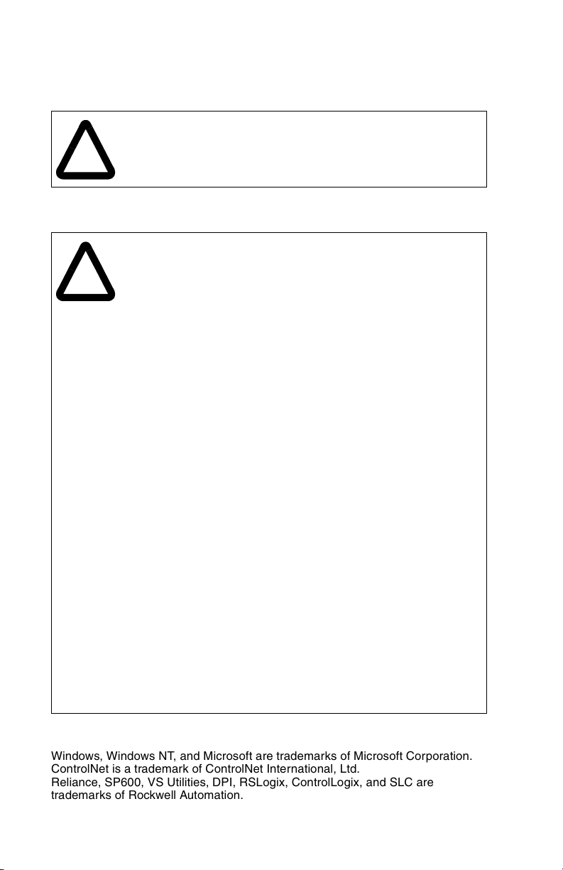
2.1 ControlNet Module Components
➊
➋
2
➎
➌➍
Status Indicators Four LEDs that indicate the status of the
➊
DPI Connector A 20-pin, single-row shrouded male header. An
➋
Channel A BNC
➌
Receptacle
Channel B BNC
➍
Receptacle
ControlNet Node
➎
Address Switches
Figure 2.1 – Components of the ControlNet Module
Getting Started
ControlNet channel(s), DPI, and the module. Refer
to chapter 8 for more information.
Internal Interface cable is connected to this
connector and a connector on the drive.
Channel “A” BNC connection for the ControlNet
cable.
Channel “B” BNC is an optional connection for the
redundnat ControlNet cable.
Switches for setting the node address.
2-1
Page 12

2.2 Required Equipment
Table 2.1 lists the equipment shipped with the ControlNet module.
When you unpack the module, verify that the package includes all of
these items.
Table 2.1 – Equipment Shipped with the ControlNet Module
Item Description
One RECOMM-CNET ControlNet module
A 2.54 cm (1 in) and a 15.24 cm (6 in) Internal Interface cable
(only one cable is needed to connect the module to the drive)
One grounding wrist strap
ControlNet Module User Manual (D2-3497)
Table 2.2 lists user-supplied equipment also required to install and
configure the ControlNet module.
Table 2.2 – Required User-Supplied Equipment
Item Description
A small flathead or Phillips screwdriver
Configuration tool, such as:
LCD OIM
•
VS Utilities (version 1.01 or later)
•
• with RECOMM-232 Serial Converter
RSNetWorx for ControlNet (version 3.00.00 or later)
Controller configuration software (for example, RSLogix 5,
RSLogix 500, or RSLogix 5000)
A PC connection to the ControlNet network, such as:
1784-PCC
•
1770-KFC
•
1784-KTCX
•
2-2
ControlNet Communications Module
Page 13

2.3 Installation Checklist
This section is designed to help experienced users start using the
ControlNet module. If you are unsure about how to complete a step,
refer to the referenced chapter.
✔ Step Action Refer to
❒
❒
❒
❒
❒
❒
❒
1
Review the safety precautions for the
module.
2
Verify that the drive is properly installed.
3
Install the module.
Verify that the drive is not powered. Then,
connect the module to the network using a
ControlNet cable and to the drive using the
Internal Interface cable. Use the captive
screws to secure and ground the module to
the drive.
4
Apply power to the module.
The module receives power from the drive.
Apply power to the drive. The status
indicators should be green. If they flash red,
there is a problem. Refer to chapter 8,
Troubleshooting the ControlNet Module and
the Network.
5
Configure the module for your
application.
Set the parameters for the following features
as required by your application:
I/O configuration.
•
Fault actions.
•
6
Apply power to the ControlNet master and
other devices on the network.
Verify that the master and network are
installed and functioning in accordance with
ControlNet standards, and then apply power
to them.
7
Configure the scanner to communicate
with the module.
Use a network tool for ControlNet to
configure the master on the network.
Throughout
this manual
SP600 AC
Drive User
Manual
Chapter 3,
Installing the
ControlNet
Module
Chapter 3,
Installing the
ControlNet
Module
Chapter 4,
Configuring
the
ControlNet
Module
Chapter 5,
RSNetWorx
Configuration
for PLC-5C
Applications
Getting Started
2-3
Page 14

✔
Step Action Refer to
8
❒
Create a ladder logic program.
Use a programming tool to create a ladder
logic program that enables you to do the
following:
Control the module and connected drive.
•
Monitor or configure the drive using Explicit
•
Messages.
Chapter 6,
PLC-5C
Applications
2-4
ControlNet Communications Module
Page 15

C
HAPTER
Installing the
ControlNet Module
Chapter 3 provides instructions for installing the module on an
SP600 drive.
3.1 Preparing for an Installation
Before installing the ControlNet module, verify that you have all
requirement equipment. Refer to chapter 2, Getting Started, for a
list of equipment.
3.2 Commissioning the Module
To commission the module, you must set a unique node address on
the network. (Refer to the Glossary for details about node
addresses.)
3
Important:
!
Important:
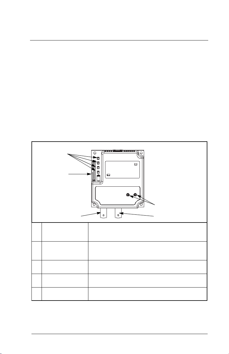
Step 1. Set the ControlNet module’s node address by rotating the
Important:
Installing the ControlNet Module
New settings are recognized only when power is
applied to the module or it is reset. If you change a
setting, cycle power or reset the module.
ATTENTION:
(Electrostatic Discharge) sensitive parts that can be
damaged if you do not follow ESD control
procedures. Static control precautions are required
when handling the module. Failure to observe these
precautions could result in damage to equipment.
To guard against device malfunction, you must wear a
grounding wrist strap when installing the ControlNet
module.
node address switches to the desired value for each digit
as shown in figure 3.1.
Each node on the ControlNet network must have a
unique address.
The ControlNet module contains ESD-
3-1
Page 16
Important:
The node address must be set before power is applied
because the module uses the node address it detects
when it first receives power. To change a node
address, you must set the new value and then remove
and reapply power to or reset the module.
2
3
4
1
0
5
9
6
4
5
6
7
8
Ones
Digit
0
1
9
2
8
Tens
Digit
3
7
Setting Description
0 to 99 Node address used by the module if switches are enabled.
The default switch setting is 02.
Important:
If the address switch is set to “00”, the module
will use the setting of CN Addr Cfg (03) for the node
address. Refer to chapter 4, Configuring the ControlNet
Module, for more information.
Figure 3.1 – Setting the Module’s Node Address
3.3 Connecting the Module to the Drive
Step 1. Remove power from the drive.
Step 2. Use static control precautions.
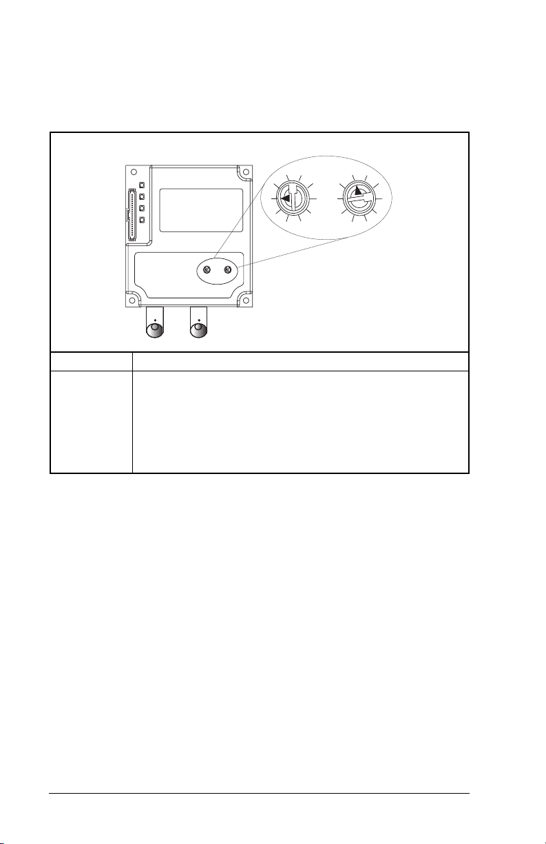
Step 3. Connect the Internal Interface cable to the DPI port on the
drive and then to the DPI connector on the module. See
figure 3.2.
3-2
ControlNet Communications Module
Page 17
➊
ControlNet Module
➌
➋
SP600 Drive
1-20 HP @ 460 V
SP600 Drive
25-40 HP @ 460 V
➊
➋
➌
Installing the ControlNet Module
DPI Connector
15.24 cm (6 in) Internal Interface cable
2.54 cm (1 in) Internal Interface cable
Figure 3.2 – DPI Ports and Internal Interface Cables
Step 4. For 1-20 HP SP600 drives, fold the Internal Interface
cable behind the module and mount the module on the
drive using the four captive screws. See figure 3.3.
For 25-40 HP SP600 drives, mount the module on the
drive using the four captive screws to secure and ground
it to the drive.
3-3
Page 18
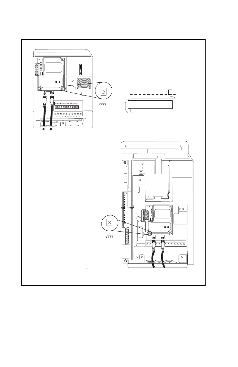
Important:
All screws must be tightened since the module is
grounded through a screw.
SP600 1-20 HP Drive
Drive
Module
Adapter
Internal Interface Cable
Folded Behind the Module
and in Front of the Drive
3-4
SP600 Drive
25-40 HP @ 460 V
Figure 3.3 – Mounting the Module
ControlNet Communications Module
Page 19
3.4 Connecting the Module to the Network
ATTENTION:
voltages that can cause injury or death. Remove
!
Step 1. Remove power from the drive.
Step 2. Use static control precautions.
Step 3. Route the ControlNet cable through the bottom of the
Step 4. Connect the ControlNet cable to the module.
See figure 3.4 for typical ControlNet network wiring.
power from the drive, and then verify power has
been discharged before installing or removing a
module. Failure to observe this precaution could
result in severe bodily injury or loss of life.
SP600 drive. (See figure 3.3.)
A 1786-TPS (straight tap) is recommended.
Scanner
The SP600 drive may contain high
SP600 Drive SP600 Drive
Figure 3.4 – Typical ControlNet Network Wiring
Installing the ControlNet Module
3-5
Page 20

3.5 Applying Power
ATTENTION:
if parameter settings and switch settings are not
!
Step 1. Close the door or reinstall the cover on the drive. The
Step 2. Apply power to the drive. The module receives its power
Step 3. Apply power to the master device and other devices on
compatible with your application. Verify that
settings are compatible with your application
before applying power to the drive. Failure to
observe these precations could result in severe
bodily injury of loss of life.
status indicators can be viewed on the front of the drive
after power has been applied.
from the connected drive. When you apply power to the
product for the first time, the status indicators should be
green or off after an initialization. If the status indicators
are red, refer to chapter 8.
the network.
Unpredictable operation may occur
3-6
ControlNet Communications Module
Page 21

C
Configuring the
ControlNet Module
Chapter 4 provides instructions and information for setting the
parameters in the module.
For a complete list of parameters, refer to Appendix B, ControlNet
Module Parameters. For definitions of terms in this chapter, refer to
the Glossary.
4.1 Configuration Tools
The ControlNet module stores parameters and other information in
its own non-volatile memory. Therefore, you must access the
module to view and edit its parameters. Table 4.1 lists the tools that
can be used to access the module parameters.
Table 4.1 – Configuration Tools
Tool Refer to:
VS Utilities Software VS Utilities online help
LCD OIM Section 4.2
HAPTER
4
Configuring the ControlNet Module
4-1
Page 22
4.2 Using the LCD OIM to Configure the
pp
pp
pp
g
g
g
Module
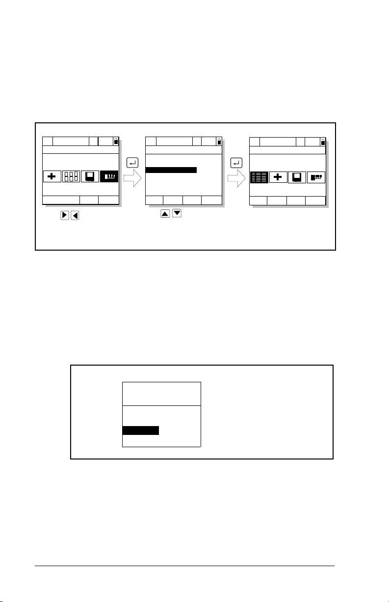
Use the procedure in figure 4.1 to access the parameters on the
ControlNet module using the LCD OIM. If you are unfamiliar with
the operation of the LCD OIM, refer to the SP600 AC Drive User
Manual (D2-3485) for more information.
>>
Sto
P0: SP600
Main Menu
Device Select
Monitor
Use to hi
Device Select icon
Auto
ed
Lan
hlight
>>
Sto
P0: SP600
Device: Port 0
SP600
RECOMM-CNET
Use to select
RECOMM-CNET.
Auto
ed
Figure 4.1 – Accessing the ControlNet Parameters using the LCD OIM
4.3 Setting the Node Address
If the node address switches are set to “00”, the value of CN Addr
Cfg (3) determines the node address.
Step 1. Set the value of CN Addr Cfg (3) to a unique node
address.
Port 5 Device
RECOMM-CNET
Parameter #: 3
CN Addr Cfg
02
0 <> 99
Default = 02
>>
Sto
P5: RECOMM-CNET
Main Menu
Parameters
Edit the ControlNet
parameters usin
same techniques as for
drive parameters.
Auto
ed
the
Figure 4.2 – ControlNet Node Address Screen on an LCD OIM
Step 2. Reset the module. Refer to section 4.7.3, Resetting the
Module.
4-2
ControlNet Communications Module
Page 23
4.4 Setting the I/O Configuration
The I/O configuration determines the type of data sent to the drive.
This is a two-part process: enabling/disabling the data transmitted
betweeen the module and the drive, and identifying the data
transmitted between the module and the scanner.
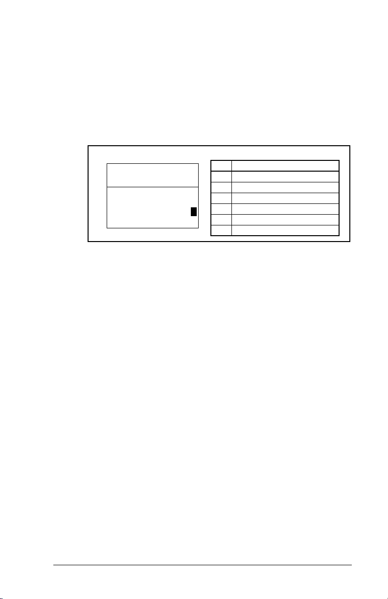
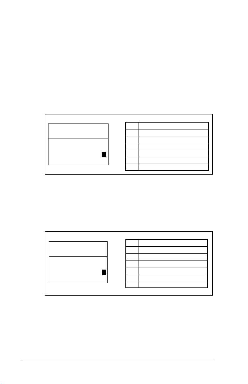
Step 1. Enable or disable the data transmitted between the
module and the drive by setting the bits in DPI I/O Config
(13). A “1” enables the I/O. A “0” disables the I/O.
Port 5 Device
RECOMM-CNET
Parameter #: 13
DPI I/O Config
xxxxxxxxxxx0000
Cmd/Ref b00
Figure 4.3 – I/O Configuration Screen on an LCD OIM
Bit Description
0 Logic Command/Reference (Default)
1 Datalink A
2 Datalink B
3 Datalink C
1
4 Datalink D
5 - 15 Not Used
Bit 0 is the right-most bit. In figure 4.3, it is highlighted and equals
“1.”
Step 2. If Logic Command/Reference is enabled (default),
configure the parameters in the drive to accept the Logic
Command and Reference from the module. For example,
set Speed Ref A Sel (90) in an SP600 drive to “Network”
so that the drive uses the Reference from the module.
Also, verify that Logic Source Sel (89) is configured to
receive the desired logic from the module.
Step 3. If you enabled one or more Datalinks (optional), configure
parameters in the drive to determine the source and
destination of data in the Datalink(s). Also, ensure that the
ControlNet module is the only module using the enabled
Datalink(s).
Step 4. Reset the module. Refer to section 4.7.3, Resetting the
Module.
The module is ready to receive I/O from the master (i.e., scanner).
You must now configure the scanner to recognize and transmit I/O
to the module. Refer to chapter 5, RSNetWorx Configuration for
PLC-5C Applications, for more information.
Configuring the ControlNet Module
4-3
Page 24
4.5 Selecting Master-Slave
A hierarchy determines the type of device with which the module
exchanges data. In a Master-Slave hierarchy, a module exchanges
data with a scanner.
To set a Master-Slave hierarchy
Step 1. Enable the desired I/O in DPI I/O Config (13). Refer to
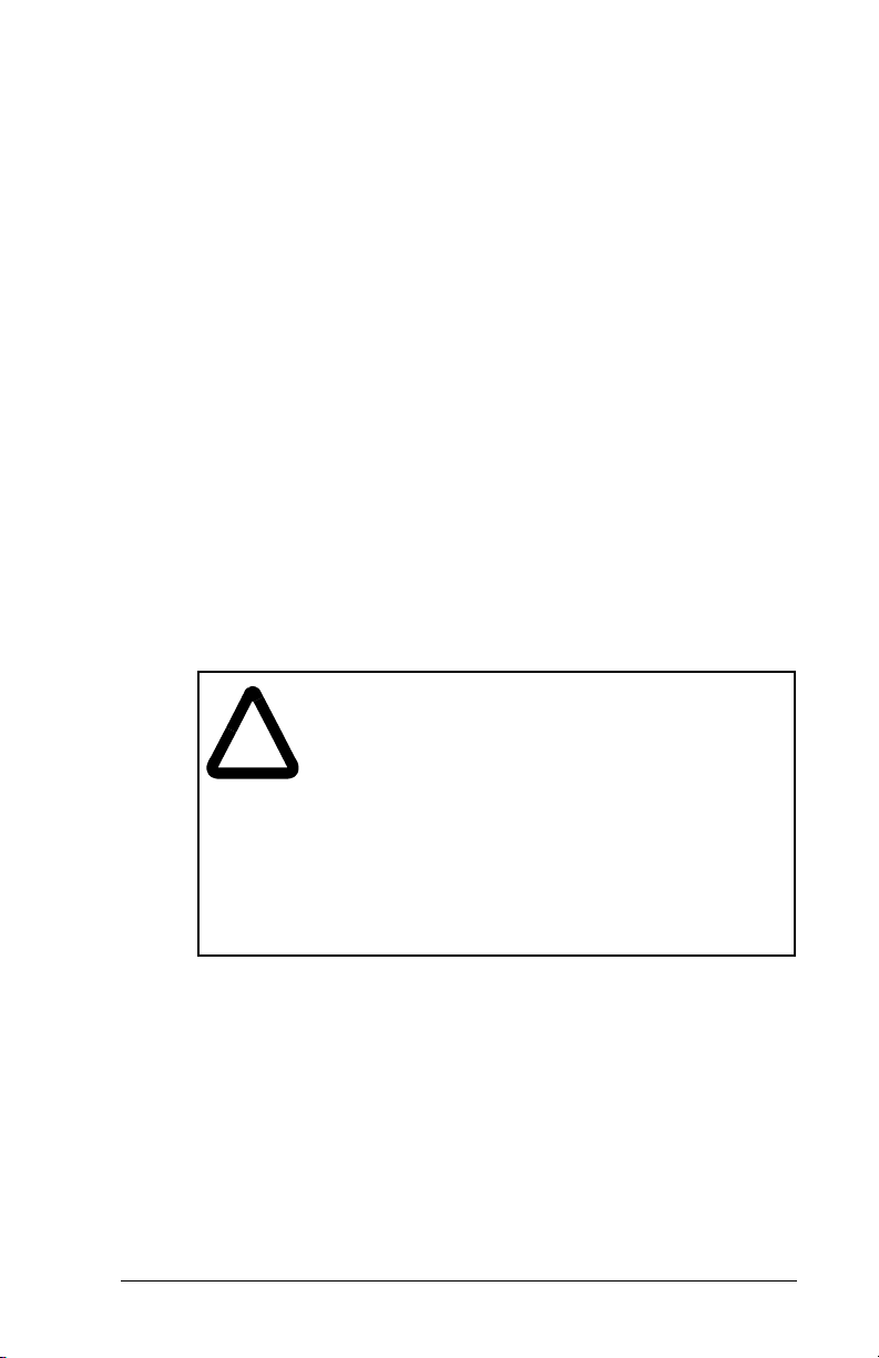
Step 2. Set the bits in the M-S Input (25). This parameter
figure 4.3.
determines the data transmitted from the scanner to the
drive. A “1” enables the I/O. A “0” disables the I/O.
Port 5 Device
RECOMM-CNET
Parameter #: 25
M-S Input
xxxx xxxx xxx0 000
Cmd/Ref b00
Figure 4.4 – Master-Slave Input Screen on an LCD OIM
1
Bit Description
0 Logic Command/Reference (Default)
1 Datalink A Input
2 Datalink B Input
3 Datalink C Input
4 Datalink D Input
5 - 15 Not Used
Bit 0 is the right-most bit. In figure 4.4, it is highlighted and equals
“1.”
Step 3. Set the bits in the M-S Output (26). This parameter
determines the data transmitted from the drive to the
scanner. A “1” enables the I/O. A “0” disables the I/O.
Port 5 Device
RECOMM-CNET
Parameter #: 26
M-S Output
xxxxxxxxxxx0000
Status/Fdbk b00
Figure 4.5 – Master-Slave Input Screen on an LCD OIM
1
Bit Description
0 Status/Feedback (Default)
1 Datalink A Output
2 Datalink B Output
3 Datalink C Output
4 Datalink D Output
5 - 15 Not Used
4-4
Bit 0 is the right-most bit. In figure 4.5, it is highlighted and equals
“1.”
Step 4. Reset the module. Refer section 4.7.3 for this procedure.
ControlNet Communications Module
Page 25
The module is ready to receive I/O from the master (i.e., scanner).
You must now configure the scanner to recognize and transmit I/O
to the module. Refer to chapter 5, RSNetWorx Configuration for
PLC-5C Applications.
4.6 Selecting Reference Adjust
Reference Adjust is the percent scaling factor for the Reference
from the Network and can be set from 0-200%. This allows the
drive’s Reference to either match the network Reference (=100%),
scale below the network Reference (<100%), or scale above the
network Reference (>100%).
4.7 Setting a Fault Action
By default, when communications are disrupted (for example, a
cable is disconnected) or the master is idle, the drive responds by
faulting if it is using I/O from the network.
You can configure a different response to communication
disruptions using Comm Flt Action (10) and a different response to
an idle scanner using Idle Flt Action (11).
ATTENTION:
Action (11) let you determine the action of the module
!
Configuring the ControlNet Module
and connected Host product if the controller is idle
(for example, in program mode). These parameters
can be used to fault the Host product (default) or
perform another function such as allow the Host to
continue to run. Some ControlNet scanners may
operate differently when a controller is idle, which
could limit the Idle Fault Action’s operating states.
The Idle Flt Action should be verified when
commissioning the drive on the network by testing
the operation with the controller in idle.
Comm Flt Action (10) and Idle Flt
4-5
Page 26
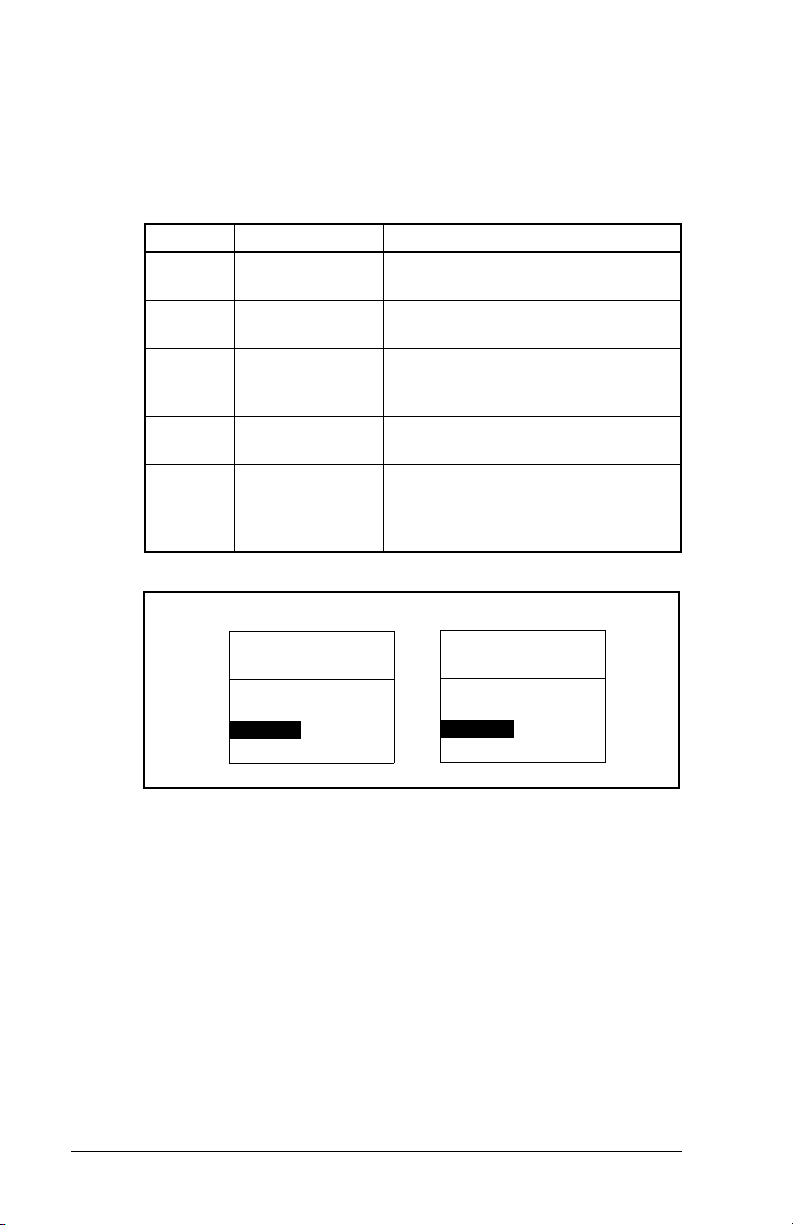
4.7.1 Changing the Fault Action
Set the values of Comm Flt Action (10) and Idle Flt Action (11) to
the desired responses as shown in table 4.2. See figure 4.6 for
sample LCD OIM Fault Action screens.
Table 4.2 – Selections for Drive Response to Communication Fault
Value Action Description
0 Fault (default) The drive is faulted and stopped
(Default).
1 Stop The drive is stopped, but not
faulted.
2 Zero Data The drive is sent 0 for output data
after a communications disruption.
This does not command a stop.
3 Hold Last The drive continues in its present
4 Send Flt Cfg The drive is sent the data that you
state.
set in the fault configuration
parameters, Flt Cfg Logic (15)
through Flt Cfg D2 In (24).
4-6
Port 5 Device
RECOMM-CNET
Parameter #: 10
Comm Flt Action
0
Fault
Figure 4.6 – Fault Action Screens on an LCD OIM
Port 5 De vice
RECOMM-CNET
Parameter #: 11
Idle Flt Action
0
Fault
Changes to these parameters take effect immediately. A reset is not
required.
ControlNet Communications Module
Page 27
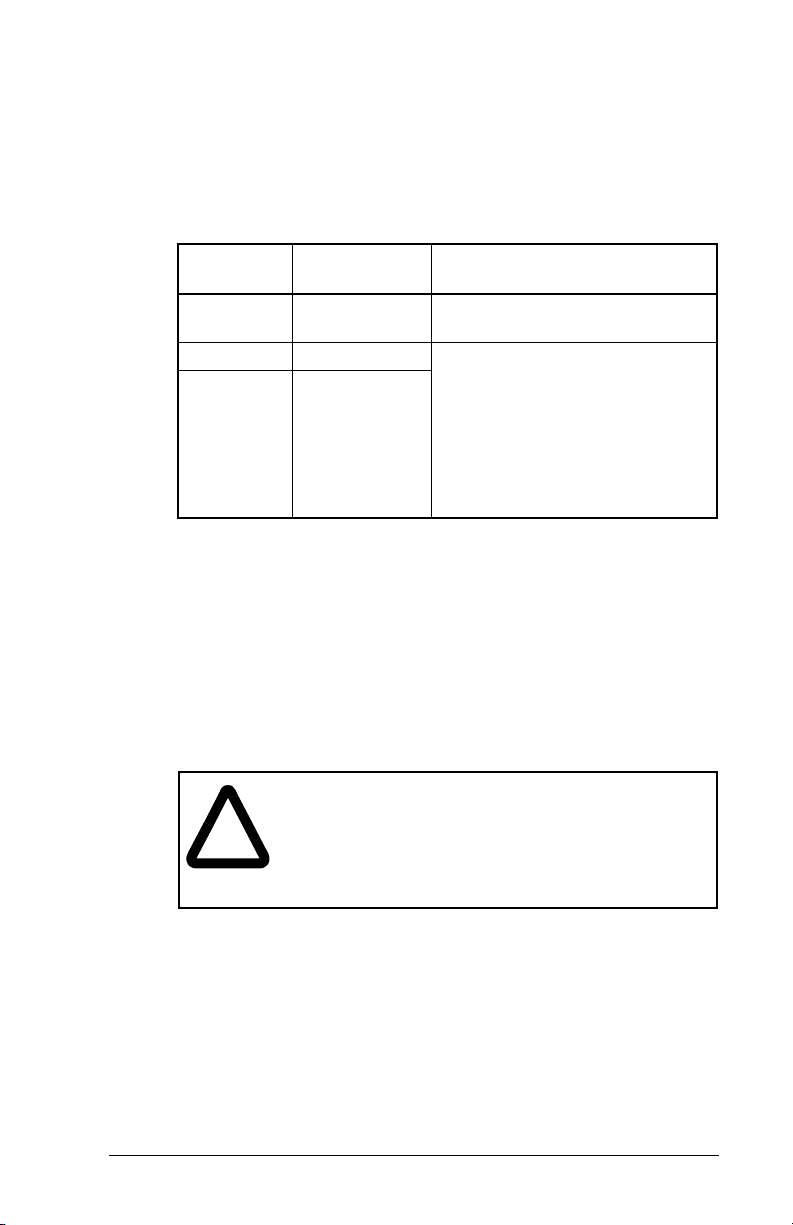
4.7.2 Setting the Fault Configuration Parameters
If you set Comm Flt Action (10) or Idle Flt Action (11) to “Send Flt
Cfg,” the values in the parameters shown in table 4.3 are sent to the
drive after a communications fault and/or idle fault occurs. You must
set these parameters to values required by your application.
Table 4.3 – Fault Configuration Parameters
Parameter
Number Name Description
15 Flt Cfg Logic A 16-bit value sent to the drive
for Logic Command.
16 Flt Cfg Ref A 32-bit value (0 to 4294967295)
17 - 24 Flt Cfg x1 In
Flt Cfg x2 In
Changes to these parameters take effect immediately. A reset is not
required.
sent to the drive as a Reference
or Datalink.
Important
16-bit Reference or 16-bit
Datalinks, the most significant
word of the value must be set to
zero (0) or a fault will occur.
: If the drive uses a
4.7.3 Resetting the Module
Changes to switch settings or some module parameters require that
you reset the module before the new settings take effect. You can
reset the module by cycling power to the drive or by using Reset
Module (9).
ATTENTION:
I/O to the drive, the drive may fault when you reset
!
Configuring the ControlNet Module
the module. Determine how your drive will respond
before resetting a connected module. Failure to
observe this precaution could result in bodily injury
or damage to equipment.
If the module is transmitting control
4-7
Page 28

Set Reset Module (9) to Reset Module. See figure 4.7.
Port 5 Device
RECOMM-CNET
Parameter #: 9
Reset Module
1
Reset Module
Figure 4.7 – Reset Screen on an LCD OIM
When you enter
1 (Reset Module)
reset. When you enter
2 (Set Defaults)
Value Description
0 Ready (Default)
1 Reset Module
2 Set Defaults
, the module will be immediately
, the module will set all
module parameters to their factory-default settings. The value of this
parameter will be restored to
0 (Ready)
after the module is reset or
resetting the defaults. The module should be reset after performing
a “Set Defaults.”
4.8 Viewing the Module Configuration
The parameters in table 4.4 provide information about how the
module is configured. You can view these parameters at any time.
Table 4.4 – Module Configuration Status Parameters
No. Name and Description
01
DPI Port
Port to which the module is connected. This will
usually be port 5.
02
DPI Data Rate
Data rate used by the drive. This data rate is set in
the drive and the module detects it.
04
CN Addr Act
The actual network node address.
06
CN Rate Act
The actual network data rate.
07
Ref/Fdbk Size
Size of the Reference/Feedback. The drive
determines the size of the Reference/Feedback.
08
Datalink Size
Size of each Datalink word. The drive determines
the size of Datalinks.
Default: 5
Minimum: 0
Maximum: 7
Type: Read Only
Default: 0 = 125 K
Values 0 = 125 K
1 = 500 K
Type: Read Only
Default: 2
Minimum: 1
Maximum: 99
Type: Read Only
Default: 0 = 5 Mbps
Values: 0 = 5 Mbps
Type: Read Only
Default: 0 = 16-bit
Values: 0 = 16-bit
Type: Read Only
Default: 0 = 16-bit
Values: 0 = 16-bit
Type: Read Only
Details
1 = 32-bit
1 = 32-bit
4-8
ControlNet Communications Module
Page 29
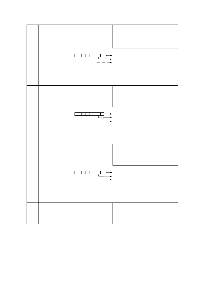
Table 4.4 – Module Configuration Status Parameters
No. Name and Description
14
DPI I/O Active
I/O that the module is actively transmitting. The
value of this parameter will usually be equal to the
value of parameter 13 - DPI I/O Config.
Bit
Default
25
M-S Input
Configures the I/O Data to be transferred from the
network to the drive.
Bit
Default
26
M-S Output
Configures the I/O Data to be transferred from the
drive to the network.
Bit
Default
27
Ref Adjust
Percent scale factor for the Reference from the
Network.
Default: xxx0 0001
Bit Values: 0 = I/O disabled
Type: Read Only
Bit Definitions
01234576
0 = Cmd/Ref
10000xxx
1 = Datalink A
2 = Datalink B
3 = Datalink C
4 = Datalink D
5 = Not Used
6 = Not Used
7 = Not Used
Default: xxx0 0001
Bit Values: 0 = I/O disabled
Type: Read/Write
Reset Required: Yes
Bit Definitions
01234576
0 = Cmd/Ref
10000xxx
1 = Datalink A
2 = Datalink B
3 = Datalink C
4 = Datalink D
5 = Not Used
6 = Not Used
7 = Not Used
Default: xxx0 0001
Bit Values: 0 = I/O disabled
Type: Read/Write
Reset Required: Yes
Bit Definitions
01234576
0 = Cmd/Ref
10000xxx
1 = Datalink A
2 = Datalink B
3 = Datalink C
4 = Datalink D
5 = Not Used
6 = Not Used
7 = Not Used
Default: 100.00
Minimum: 0.00
Maximum: 200.00
Type: Read/Write
Reset Required: No
Details
1 = I/O enabled
1 = I/O enabled
1 = I/O enabled
Configuring the ControlNet Module
4-9
Page 30

4-10
ControlNet Communications Module
Page 31
C
HAPTER
RSNetWorx Configuration
for PLC-5C Applications
This chapter provides information for using RSNetWorx for
ControlNet to configure a PLC-5C controller to communicate with
the RECOMM-CNET ControlNet module.
RSNetWorx for ControlNet is a 32-bit Windows application for
configuring ControlNet networks. After installing and configuring the
module, RSNetWorx is used to configure the controller to recognize
and communicate with the module.
Before configuring the controller, your PC must be:
Connected to the ControlNet network using a 1784-PCC,
•
1770-KFC, or similar device.
Running RSNetWorx with RSLinx communications.
•
5.1 Configuring a ControlNet Network:
5
An Example
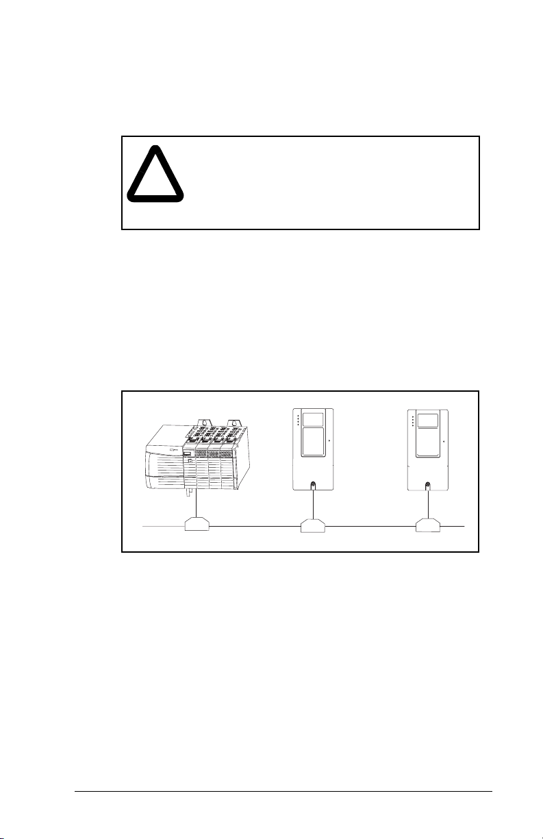
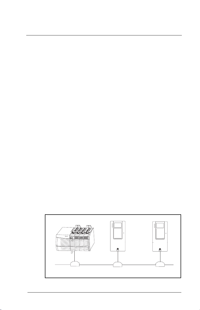
In this example, we will be configuring two SP600 drives to be
Node 2 and Node 3 on a ControlNet network. This chapter
describes the steps to configure a simple network as shown in
figure 5.1.
Scanner
Figure 5.1 – Sample ControlNet Network
RSNetWorx Configuration for PLC-5C Applications
SP600 Drive
Node 2
SP600 Drive
Node 3
5-1
Page 32

5.1.1 Installing and Registering EDS Files in
RSNetWorx
This section needs to be performed only if new EDS (Electronic
Data Sheet) files need to be added to RSNetWorx. The latest EDS
files can be obtained at:
http://www.reliance.com/prodserv/standriv/networks.
In the
Step 1. The EDS Wizard can be used to install (register) new
menu, select
T
ools
Figure 5.2 – Rockwell Software EDS Wizard
EDS files to the RSNetWorx database, remove
(unregister) EDS files from the RSNetWorx database, and
change the graphic icon used to represent the device.
Select
Register an EDS file(s)
5.3).
EDS Wizard
and click
and click
Next (
ext
N
figure 5.2).
(figure
5-2
ControlNet Communications Module
Page 33

Figure 5.3 – EDS Wizard Option Screen
Step 2. The EDS Wizard allows for registering single or multiple
EDS files. Click
B
and locate where your EDS files
rowse
are located. In our example (figure 5.4), multiple EDS files
are registered from a directory on the hard drive.
Figure 5.4 – EDS Wizard Designation Screen
RSNetWorx Configuration for PLC-5C Applications
5-3
Page 34
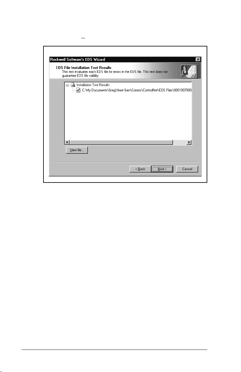
Step 3. The EDS Wizard will install and test the EDS files. A
green check mark next to each file indicates success.
Click
Figure 5.5 – EDS Files Installation Test Results Screen
to continue (figure 5.5).
N
ext
5-4
ControlNet Communications Module
Page 35

Step 4. The graphic images for each EDS file are displayed and
can be changed if desired. Click
to continue (figure
N
ext
5.6).
SP600
Figure 5.6 – EDS Wizard Change Graphic Image Screen
RSNetWorx Configuration for PLC-5C Applications
5-5
Page 36

Step 5. Click
Figure 5.7 – EDS Wizard Final Task Summary Screen
to register the EDS files (figure 5.7).
N
ext
You would like to register the following device:
SP600
5-6
Step 6. The EDS files have been installed and registered. Click
to return to the main RSNetWorx screen (figure
inish
F
5.8).
Figure 5.8 – EDS Wizard Completion Screen
ControlNet Communications Module
Page 37

Step 7. Click on the
window to view the EDS files that have been installed to
the RSNetWorx database (figure 5.9).
SP600
Figure 5.9 – RSNetWorx for ControlNet DPI to ControlNet Folder Example
DPI to ControlNet
folder in the Hardware
5.1.2 Configuring a Network with RSNetWorx
The main screen for RSNetWorx consists of several windows:
The Network Usage View displays current and pending values
•
associated with the ControlNet network configuration.
A Hardware View displays a list of all network hardware currently
•
available to RSNetWorx software.
The Favorites View displays a list of hardware that is frequently
•
used when working with the current RSNetWorx configuration.
The Graph View shows a pictorial representation of all the
•
hardware used in the current RSNetWorx configuration.
The Message View displays a log of messages which are listed
•
from top to bottom, newest to oldest. This view may contain
informational, warning, and/or error messages.
RSNetWorx Configuration for PLC-5C Applications
5-7
Page 38

The various views can be displayed or closed by using the
V
iew
menu. In figure 5.10, the Network Usage, Hardware and Graphic
views are displayed while the Message and Favorites views are
closed.
Step 1. Click the on-line icon to browse the network.
5-8
Figure 5.10 – RSNetWorx for ControlNet Screen
Step 2. Select the ControlNet network access method and click
OK. In this example, RSNetWorx will use the 1784-PCC
to access the ControlNet network (figure 5.11).
ControlNet Communications Module
Page 39
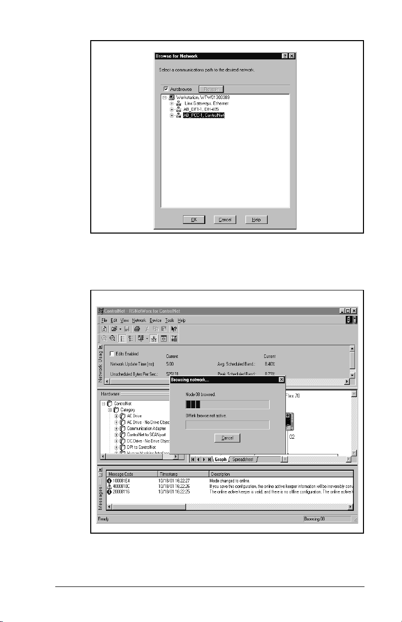
.
Figure 5.11 – Sample Browse for Network Dialog Box
RSNetWorx starts browsing the ControlNet network for nodes and
builds the graphic representation of the network (figure 5.12).
Figure 5.12 – Sample Network Displayed in RSNetWorx
RSNetWorx Configuration for PLC-5C Applications
5-9
Page 40

Step 3. When the network browse is complete, a graphical view of
the network is displayed. In this example (figure 5.13), the
ControlNet network consists of a PLC-5C/40C controller,
two SP600 drives, and a PC using a 1784-PCC.
The symbol indicates the device shown on the
network does not exist in the configuration file, but it was
found on the network. Double-click on the PLC-5C/40C
icon.
SP600 SP600
5-10
Figure 5.13 – Sample ControlNet Configuration Screen
Step 4. The ControlNet configuration box displays information
about each node (figure 5.14). Click
ControlNet Communications Module
OK.
Page 41

Figure 5.14 – Sample ControlNet Configuration Box
Step 5. The ControlNet module must be configured on the
ControlNet network so the controller can communicate
with it. Click the Edits Enabled check-box (figure 5.15).
SP600 SP600
Figure 5.15 – Example of Product Line after Drive Connection is Selected
RSNetWorx Configuration for PLC-5C Applications
5-11
Page 42

Step 6. If the On-line / Off-line Mismatch dialog box appears, click
OK to use the on-line data (figure 5.16). If prompted to
save, save the data (figure 5.17).
Figure 5.16 – Online / Offline Mismatch Dialog Box
RECOMM-CNET Exampl e.XC
5-12
Figure 5.17 – Save Data Screen
Important:
During the save process, RSNetWorx will execute the
browse function. Allow RSNetWorx to complete the
browse (1-99 nodes), even if you already see the entire
network. Canceling the browse early may cause an
improper scheduling of I/O.
Step 7. Right-click on the controller’s icon (PLC-5C) and select
CANlist Configuration
S
. The Scanlist Configuration
screen (figure 5.18), is used to configure the controller to
communicate with the nodes.
ControlNet Communications Module
Page 43
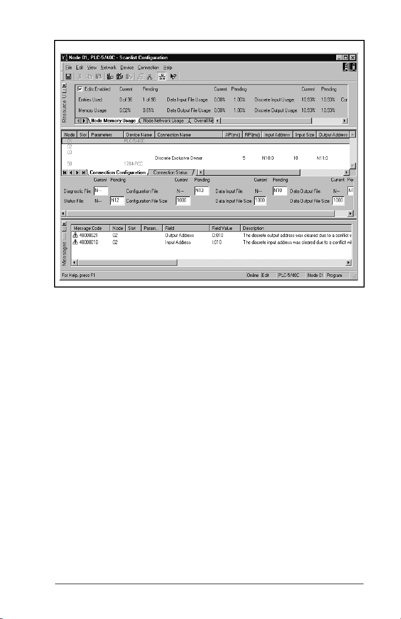
..
SP600
SP600
Figure 5.18 – Scanlist Configuration Screen
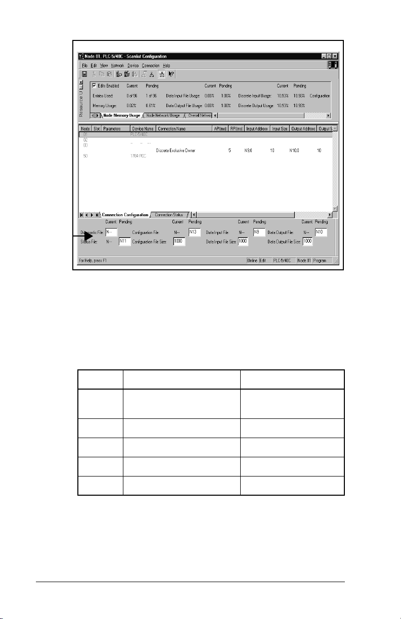
Step 8. Enter the Integer files to be used for ControlNet
communications (figure 5.19). In this example, N9 is the
Data Input File, N10 is the Data Output File, N11 is the
Status File, and N13 is the Configuration File. Doubleclick the Node 2 row (SP600 drive).
RSNetWorx Configuration for PLC-5C Applications
5-13
Page 44
SP600
SP600
Figure 5.19 – Integer Files for ControlNet Communications Screen
Step 9. Enter the input and output size for the node on the
network. The number of words selected depends on the
I/O to be communicated with the node. In this example,
the Node 2 SP600 is set for all I/O enabled which equates
to 10 words of I/O (table 5.1).
Table 5.1 – Input/Output Table
Words Input to PLC-5C Output to PLC-5C
5-14
0-1 Logic Command /
Reference
Logic Status /
Feedback
2-3 Datalinks A1 & A2 Out Datalinks A1 & A2 In
4-5 Datalinks B1 & B2 Out Datalinks B1 & B2 In
6-7 Datalinks C1 & C2 Out Datalinks C1 & C2 In
8-9 Datalinks D1 & D2 Out Datalinks D1 & D2 In
Important:
The size of the Reference (Ref/Fdbk Size (7)) and
Datalinks (Datalink Size (8)) will affect the size you
configure for the network I/O. For example, 32-bit
Datalinks requires twice as many words as 16-bit
Datalinks. Depending on your application, the
configured I/O size may vary.
ControlNet Communications Module
Page 45

Note the values in the Input Address and Output Address fields.
These are needed to develop a ladder program.
Step 10. Enter the desired Requested Packet Interval (RPI) and
note the value (figure 5.20). Ensure that this value is
equal to or greater than the value that will be set later for
Network Update Time (NUT). The Actual Packet Interval
(API) may vary from the Requested Packet Interval.
SP600
Figure 5.20 – Communicaiton Properties
Step 11. Click the
Electronic Keying
used to determine the criteria used for the scanner to
establish a connection to a node. Select the settings
according to your application needs (figure 5.21).
RSNetWorx Configuration for PLC-5C Applications
tab. Electronic Keying is
5-15
Page 46

Figure 5.21 – Connection Properties: Electronic Keying Settings
Step 12. Click the
choosing connection options are determined by the EDS
file for the node. Click OK.
Figure 5.22 – Connection Properties: Details Settings
(figure 5.22) tab. The availability of
Details
5-16
ControlNet Communications Module
Page 47

Step 13. Repeat steps 9-12 for additional nodes. When complete,
all of the nodes should be mapped (figure 5.23).
SP600
SP600
Figure 5.23 – ScanList Configuration: Mapped Nodes
Step 14. Click
F
ile / Save
to save the project (figure 5.24). If
prompted to optimize and re-write schedule for all
connections, click
Figure 5.24 – Save Configuration Dialog Box
RSNetWorx Configuration for PLC-5C Applications
K.
O
5-17
Page 48

Step 15. Enter a file name and click
saved for future use.
RECOMM-CNET Example.XC
Figure 5.25 – Save As File Box
S
ave
5.1.3 Verifying Network Properties
. The project is now
In the
N
etwork
dialog box (figure 5.26). Verify:
The number in the
•
or equal to the highest node number that will perform I/O
messaging.
The number in the
•
than or equal to the highest node number on the network.
The correct type of media redundancy is selected in the
•
Redundancy
Important:
menu, select
Max S
Max U
field.
The value in the
5 ms or greater. Do not set lower than 5 ms. The NUT
must be set equal or lower than the RPI times set for
the devices on the network.
Properties
cheduled Address
nscheduled Address
Network Update T
to display the ControlNet
field is higher than
field is higher
ime (ms)
M
edia
field is
5-18
ControlNet Communications Module
Page 49

Figure 5.26 – ControlNet Dialog Box
Step 16. If a special media configuration is required (e.g.,
repeater), select the
Media Configuration
tab (figure
5.27) and make the appropriate changes. Refer to the
RSNetWorx on-line help for more information.
Figure 5.27 – ControlNet: Media Configuration Tab
RSNetWorx Configuration for PLC-5C Applications
5-19
Page 50

Step 17. If desired, select the
description for the network (figure 5.28). Click OK.
RECOMM-CNET Contr o l Net demonstration
program using two SP600 demo units .
Figure 5.28 – ControlNet: General Tab
Step 18. In the
etwork
N
menu, select
download them to the PLC. The module(s) are now
mapped on the network and the controller will
communicate with it.
General
tab and enter a name and
the properties and
Save
5-20
ControlNet Communications Module
Page 51

C
HAPTER
6
PLC-5C Applications
Chapter 6 provides information and examples that explain how to
use I/O Messaging and Explicit Messaging to control, configure, and
monitor an SP600 drive using a PLC-5C.
ATTENTION:
intended solely for purposes of example. There are
many variables and requirements with any
!
application. Rockwell Automation does not assume
responsibility or liability (to include intellectual
property liability) for actual use of the examples
shown in this publication. Failure to observe this
precaution could result in bodily injury or damage to
equipment.
The examples in this publication are
6.1 About I/O Messaging
I/O messaging is used to transfer the data which controls the SP600
drive and sets its Reference. I/O can also be used to transfer data to
and from Datalinks in SP600 drives.
The ControlNet module provides options for configuring and using
I/O, including the following:
The size of I/O can be configured by enabling or disabling the
•
Logic Command/Reference and Datalinks.
Chapter 4, Configuring the ControlNet Module, and Chapter 5,
RSNetWorx Configuration for PLC-5C Applications, discuss how to
configure the module and scanner on the network for these options.
The Glossary defines the different options. This chapter discusses
how to use I/O after you have configured the module and scanner.
PLC-5C Applications
6-1
Page 52

6.2 Understanding the I/O Image
The terms
view. Therefore, output I/O is data that is output from the scanner
and consumed by the ControlNet module. Input I/O is status data
that is produced by the module and consumed as input by the
scanner.
The I/O image table will vary based on the following:
Size (either 16-bit or 32-bit) of the Reference/Feedback (Ref/Fdbk
•
Size (07)) words and Datalink words used by the drive.
Size (either 16-bit or 32-bit) of the Datalink words (Datalink Size
•
(08)). If all I/O is not enabled, the image table is truncated. The
image table always uses consecutive words starting at word 0.
Figure 6.1 illustrates an example of an I/O image with 16-bit
words.The configuration is shown to illustrate utilizing 10 words of
inputs and 10 words of outputs. Depending on your application
needs, this may vary.
input
and
are defined from the scanner’s point of
output
6-2
ControlNet Communications Module
Page 53

Controller
Scanner
Output
Image
(Write)
ControlNet
Module SP600 Drive
DPI
Word and I/O
0 Logic Command
1 Reference
2 Datalink In A1
3 Datalink In A2
4 Datalink In B1
5 Datalink In B2
6 Datalink In C1
7 Datalink In C2
8 Datalink In D1
9 Datalink In D2
Logic Command
Reference
Data In A1
Data In A2
Data In B1
Data In B2
Data In C1
Data In C2
Data In D1
Data In D2
Message
Handler
Input
Image
(Read)
Message
Handler
Figure 6.1 – Sample I/O Image with All I/O Enabled
Message
Buffer
0 Logic Status
1 Feedback
2 Datalink Out A1
3 Datalink Out A2
4 Datalink Out B1
5 Datalink Out B2
6 Datalink Out C1
7 Datalink Out C2
8 Datalink Out D1
9 Datalink Out D2
Message
Buffer
Message
Handler
Logic Status
Feedback
Data Out A1
Data Out A2
Data Out B1
Data Out B2
Data Out C1
Data Out C2
Data Out D1
Data Out D2
Message
Handler
An image that uses 32-bit words for Reference and Datalinks A and
D would change the I/O image in figure 6.1 as follows:
Word I/O Word I/O
0 Logic Command/Status 8 - 11 Datalink B1/B2
1 Pad Word 12 - 15 Datalink C1/C2
2 - 3 Reference/Feedback 16 - 19 Datalink D1/D2
4 - 7 Datalink A1/A2
PLC-5C Applications
6-3
Page 54

Figure 6.2 illustrates an example of an I/O image that does not use
all of the I/O data. Only the Logic Command/Reference and
Datalink B are enabled. In this example, the Reference is a 32-bit
word, and Datalinks are 16-bit words.
ControlNet
Controller
LSW = Least Signicant Word (Bits 15 - 0)
MSW = Most Significant Word (Bits 31 - 16)
Scanner Module SP600 Drive
Output
Image
(Write)
Input
Image
(Read)
Word and I/O
0 Logic Command
1 Pad Word
2 Reference (LSW)
3 Reference (MSW)
4 Datalink In B1
5 Datalink In B2
0 Logic Status
1 Pad Word
2 Feedback (LSW)
3 Feedback (MSW)
4 Datalink Out B1
5 Datalink Out B2
DPI
Logic Command
Reference
Data In A1
Data In A2
Data In B1
Data In B2
Data In C1
Data In C2
Data In D1
Data In D2
Logic Status
Feedback
Data Out A1
Data Out A2
Data Out B1
Data Out B2
Data Out C1
Data Out C2
Data Out D1
Data Out D2
Figure 6.2 – Sample I/O Image with Only Logic/Reference and Datalink B
Enabled
6.3 Using Logic Command/Status
When enabled, the Logic Command/Status word is always word 0 in
6-4
the I/O image. The
Logic Command
produced by the scanner and consumed by the module. The
is a 16-bit word of status produced by the module and
Status
consumed by the scanner.
This manual contains the bit definitions for compatible products
available at the time of publication in Appendix D, Logic Command/
Status Words. For other products, refer to their documentation.
is a 16-bit word of control
ControlNet Communications Module
Logic
Page 55

6.4 Using Reference/Feedback
The
Reference
consumed by the module. The
produced by the module and consumed by the controller. The size
of the Reference/Feedback is determined by the drive and displayed
in Ref/Fdbk Size (07) in the module.
Size Valid Values In I/O Image Example
16-bit -32768 to 32767 Word 1 Figure 6.1
32-bit -2147483648 to 2147483647 Word 2 and Word 3 Figure 6.2
(16 bits or 32 bits) is produced by the controller and
Feedback
6.5 Using Datalinks
A Datalink is a mechanism used by SP600 drives to transfer data to
and from the controller. Datalinks allow a parameter value to be
changed without using an Explicit Message.
When enabled, each Datalink consumes either two 16-bit or 32-bit
words in both the input and output image depending on its size. The
size of Datalinks (16-bit words or 32-bit words) is determined by the
drive and displayed in Datalink Size (08) in the module.
6.5.1 Rules for Using Datalinks
Each set of Datalink parameters in an SP600 drive can be used
•
by only one module. If more than one module is connected to a
single drive, multiple modules must not try to use the same
Datalink.
Parameter settings in the drive determine the data passed
•
through the Datalink mechanism. Refer to the documentation for
your drive.
When you use a Datalink to change a value, the value is not
•
written to the Non-Volatile Storage (NVS). The value is stored in
volatile memory and lost when the drive loses power.
(16 bits or 32 bits) is
PLC-5C Applications
6-5
Page 56

6.5.2 32-Bit Parameters using 16-Bit Datalinks
To read (and/or write) a 32-bit parameter using 16-bit Datalinks,
typically both Datalinks (x1 and x2) are set to the 32-bit parameter.
For example, to read Elapsed MWh (9) in an SP600 drive, both
Datalink A1 and A2 are set to “9.” Datalink A1 will contain the least
significant word (LSW) and Datalink A2 the most significant word
(MSW). In this example, the parameter 9 value of 5.8 MWh is read
as a “58” in Datalink A1.
Datalink
Most/Least
Significant Word Parameter
Data
(decimal)
A1 LSW 9 58
A2 MSW 9 0
Regardless of the Datalink combination, x1 will always contain the
LSW and x2 will always contain the MSW. In the following examples
Power Up Marker (242) contains a value of 88.4541 hours.
Datalink
Most/Least
Significant Word Parameter
Data
(decimal)
A1 LSW 242 32573
A2 - Not Used - 0 0
Datalink
Most/Least
Significant Word Parameter
Data
(decimal)
A1 - Not Used - 0 0
A2 MSW 242 13
Datalink
Most/Least
Significant Word Parameter
Data
(decimal)
A2 MSW 242 13
B1 LSW 242 32573
6-6
32-bit data is stored in binary as follows:
MSW
LSW
31
through 2
2
15
through 2
2
16
0
Example:
Power Up Marker (242) = 88.4541 hours
MSW = 13
decimal
= 1101
= 219 + 218 + 216 = 851968
binary
LSW = 32573
851968 + 32573 = 884541
ControlNet Communications Module
Page 57

6.6 Function of the Sample Program
The program performs the following actions:
Obtains Logic Status information from the drive.
•
Uses the Logic Command to control the drive (for example, start,
•
stop).
Sends a Reference to the drive and receives Feedback from the
•
drive.
Sends/Receives Datalink data to/from the drive.
•
Module Settings for the Sample Program
Nodes 2 and 3.
•
See Chapter 5, RSNetWorx Configuration for PLC-5C
•
Applications.
Parameter Settings for the Sample Program
Table 6.1 – Parameter Settings for the Sample Program
Device Parameter Name Value Description
90 Speed Ref A Sel 22 ‘Network’ (RECOMM-CNET)
300 Data In A1 140 Points to 140 (Accel Time 1)
301 Data In A2 142 Points to 142 (Decel Time 1)
302 Data In B1 100 Points to 100 (Jog Speed)
SP600 Drive
RECOMM-CNET
303 Data In B2 155 Points to 155 (Stop Mode A)
310 Data Out A1 140 Points to 140 (Accel Time 1)
311 Data Out A2 142 Points to 142 (Decel Time 1)
312 Data Out B1 100 Points to 100 (Jog Speed)
313 Data Out B2 155 Points to 155 (Stop Mode A)
13 DPI I/O Cfg xxx1 1111 Enables Cmd/Ref, Datalinks A-D
25 M-S Input xxx1 1111 Configures the I/O Data to be
26 M-S Output xxx1 1111 Configures the I/O Data to be
transferred from the network to the
drive.
transferred from the drive to the
network.
Logic Command/Status Words
These examples use the Logic Command word and Logic Status
word for SP600 drives. Refer to Appendix D, Logic Command/
Status Words to view these. The definition of the bits in these words
may vary if you are using a different DPI product. Refer to the
documentation for your drive.
PLC-5C Applications
6-7
Page 58

6.7 Main Program (PLC-5C)
There is an operator station wired into the local rack as follows:
I:000/0 Start (Normally Open Pushbutton)
I:000/1 Stop (Normally Closed Pushbutton)
I:000/2 Clear Faults (Normally Open Pushbutton)
I:000/3 Forward / Reverse Selector Switch
I:001 Operator Speed Reference
O:000/0 Drive Ready
O:000/1 Drive Active
O:000/2 Drive Faulted
O:001 Operator Speed Feedback
The RECOMM-CNET on the SP600 drive is mapped as follows:
The 20-COMM-C on the PowerFlex 70 drive is mapped as follows:
N9:0 Logic Status N10:0 Logic Command
N9:1 Feedback N10:1 Reference
N9:2 Datalink A1 Out N10:2 Datalink A1 In
N9:3 Datalink A2 Out
N9:4 Datalink B1 Out N10:4 Datalink B1 In
N9:5 Datalink B2 Out N10:5 Datalink B2 In
N9:6 Datalink C1 Out N10:6 Datalink C1 In
N9:7 Datalink C2 Out N10:7 Datalink C2 In
N9:8 Datalink D1 Out N10:8 Datalink D1 In
N9:9 Datalink D2 Out N10:9 Datalink D2 In
Operator
Start
Pushbutton
I:000
0000
0
N10:3 Datalink A2 In
Drive
Logic Command
START
N10:0
1
6-8
0001
Operator
Stop
Pushbutton
I:000
1
Drive
Logic Command
STOP
N10:0
0
Figure 6.3 – I/O Messaging
ControlNet Communications Module
Page 59

002
003
004
005
006
Operator
Clear Faults
Pushbutton
I:000
2
Operator
Fwd / Rev
Selector Switch
I:000
3
Operator
Fwd / Rev
Selector Switch
I:000
3
Drive
READY
Status
Bit
N9:0
0
Drive
ACTIVE
Status
Bit
N9:0
1
Drive
Logic Command
CLEAR FAULTS
N10:0
3
Drive
Logic Command
FORWARD
N10:0
4
Drive
Logic Command
REVERSE
N10:0
5
Operator
Drive Ready
Status
Display
O:000
Operator
Drive Active
Status
Display
O:000
0
1
PLC-5C Applications
Figure 6.4 – I/O Messaging (Continued)
6-9
Page 60

Drive
FAULTED
Status
Bit
N9:0
007
7
This rung moves the Speed Reference from the operator station to the
drive.
008
Move
Source I:001
0<
Dest N10:1
0<
The rung moves the Speed Feedback from the drive to the operator
station.
009
Move
Source N9:1
0<
Dest O:001
0<
This rung moves Datalink data (N7) to the drive, where it is moved
into parameters.
Drive
Datalink A1 In
010
Copy File
Source #N7:0
Dest #N10:2
Length 8
MOV
MOV
MOV
MOV
COP
COP
Operator
Drive Faulted
Status
Display
O:000
2
6-10
Figure 6.5 – I/O Messaging (Continued)
ControlNet Communications Module
Page 61

This rung moves Datalink data from the drive to file N7.
011
COP
COP
Copy File
Source #N9:2
Dest #N7:10
Length 8
This rung executes the messaging logic.
012
013
Figure 6.6 – I/O Messaging (Continued)
JSR
JSR
Jump To Subroutine
Prog File Number U:3
END
PLC-5C Applications
6-11
Page 62

6.8 About Explicit Messaging
Explicit Messaging is used to transfer data that does not require
continuous updates. With Explicit Messaging, you can configure
and monitor a slave device’s parameters on the ControlNet network.
6.8.1 Performing Explicit Messages
Important:
➎
Complete Parameter
Message
➍
Retrieve Parameter
Message Response
➊
➋
➌
➍
➎
There are five basic events in the Explicit Messaging
process defined below. The details of each step will
vary depending on the controller. Refer to the
documentation for your controller.
➊
Set up and send
Parameter M es sa g e
➋
➌
Format the required data and set up the ladder
logic program to send an Explicit Message
request to the scanner module (download).
The scanner module transmits the Explicit
Message Request to the slave device over the
ControlNet network.
The slave device transmits the Explicit Message
Response back to the master.
The controller retrieves the Explicit Message
Response.
The Explicit Message is complete.
Figure 6.7 – Explicit Message Process
6-12
Important:
The scanner module may be integrated with the
controller (e.g., PLC-5C).
ControlNet Communications Module
Page 63

The ControlNet I/O Transfer (CIO) instruction is used to send
Explicit Messages. For PLC-5C controllers before Series F Revision
C, the available services you should use are Get Attribute Single,
Get Attribute All, Set Attribute Single, or Set Attribute All. Series F
Revision C (or later) allow for more complex messages using a new
Generic Bi-Directional communication command.
6.8.2 Explicit Messaging Examples
This rung sends a message to the drive over ControlNet and receives
the response from the drive. The message to be sent is built in data
file N13 while the response data is placed in data file N14.
User Logic
Message
Initiate
000
001
N7:2
0
Figure 6.8 – Explicit Messaging
A Get Attributes Scattered message allows for reading multiple
parameters that may or may not be in sequential order (figure 6.9).
A Service Code of “4B” indicates the Get_Attributes_Scattered
•
service (see page C-20, Object Specific Services).).
A Class Number of “93” indicates accessing the DPI Parameter
•
Object (see page C-16, DPI Parameter Object).
An Instance Number of “0” accesses the Class Attributes (see
•
page C-16, Instances).
N13:0-11 contains the request message and N14:0-11 contains
•
the response message (see page C-20, Format for
Get_Attributes_Scattered Service).
CIO
CIO
ControlNet I/O Transfer
Control CT12:0
Setup Screen
EN
DN
ER
END
PLC-5C Applications
6-13
Page 64

Figure 6.9 – CIO Get Attributes Scattered Screen
Get Attributes Scattered Example request and response Data:
Request Data
N13:0 12 Parameter Number = 12
N13:1 0 (Pad Word)
N13:2 0 (Pad Word)
N13:3 11 Parameter Number = 11
N13:4 0 (Pad Word)
N13:5 0 (Pad Word)
N13:6 10 Parameter Number = 10
N13:7 0 (Pad Word)
N13:8 0 (Pad Word)
N13:9 9 Parameter Number = 9
N13:10 0 (Pad Word)
N13:11 0 (Pad Word)
6-14
ControlNet Communications Module
Page 65

Response Data
N14:0 12 Parameter Number = 12
N14:1 3333 Value = 333.3VDC
N14:2 0 (Pad Word)
N14:3 11 Parameter Number = 11
N14:4 0 Value = 0.0Hz
N14:5 0 (Pad Word)
N14:6 10 Parameter Number = 10
N14:7 148 Value = 14.8Hrs
N14:8
N14:9 9 Parameter Number = 9
N14:10 23 Value = 2.3MWh
N14:11
A Set Attributes Scattered message is used to write multiple
parameters that may or may not be in sequential order (figure 6.10).
A Service Code of “4C” indicates the Set_Attributes_Scattered
•
service (see page C-19, Object Specific Services).
PLC-5C Applications
Figure 6.10 – CIO Set Attributes Scattered Screen
6-15
Page 66

Set Attributes Scattered Example request and response Data:
Request Data
N13:0 45 Parameter Number = 45
N13:1 50 Value = 0.50HP
N13:2 0 (Pad Word)
N13:3 44 Parameter Number = 44
N13:4 1740 Value = 1740RPM
N13:5 0 (Pad Word)
N13:6 43 Parameter Number = 43
N13:7 600 Value = 60.0Hz
N13:8 0 (Pad Word)
N13:9 42 Parameter Number = 42
N13:10 16 Value = 1.6Amps
N13:11 0 (Pad Word)
Response Data
N14:0 45 Parameter Number = 45
N14:1 0 (Pad Word)
N14:2 0 (Pad Word)
N14:3 44 Parameter Number = 44
N14:4 0 (Pad Word)
N14:5 0 (Pad Word)
N14:6 43 Parameter Number = 43
N14:7 0 (Pad Word)
N14:8 0 (Pad Word)
N14:9 42 Parameter Number = 42
N14:10 0 (Pad Word)
N14:11 0 (Pad Word)
6-16
A Get Attribute Single message is used to read a single parameter
(figure 6.11).
A Service Code of “E” indicates the Get_Attribute_Single service
•
(see page C-20, Common Services).
An Instance Number of “1” indicates Drive Parameter 1 will be
•
accessed (see page C-16, Instances).
An Attribute Number of “9” indicates the Parameter Value
•
Attribute will be accessed (see page C-17, Instance Attributes).
ControlNet Communications Module
Page 67
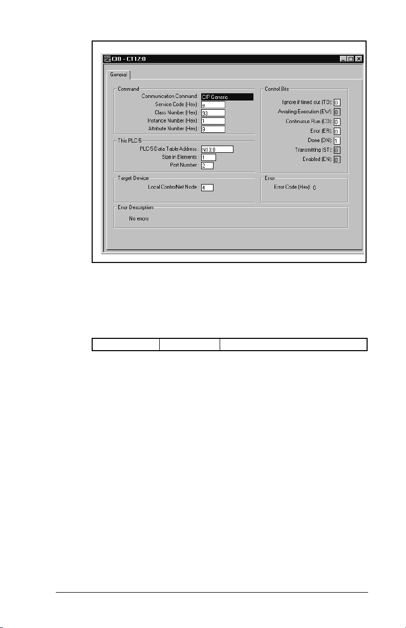
Figure 6.11 – CIO Get Attribute Single Screen
Get Attribute Single example response (reading SP600 Parameter 1
in figure 6.11):
Response Data
N14:0 0 Value = 0.0Hz
A Set_Attribute_Single message is used to write a single parameter
(figure 6.12).
A Service Code of “10” indicates the Set_Attribute_Single service
•
(see page C-20, Common Services).
An Instance Number of “41” indicates Drive Parameter 41 will be
•
accessed (see page C-16, Instances).
An Attribute Number of “9” indicates the Parameter Value
•
Attribute will be written (see page C-17, Instance Attributes).
PLC-5C Applications
6-17
Page 68
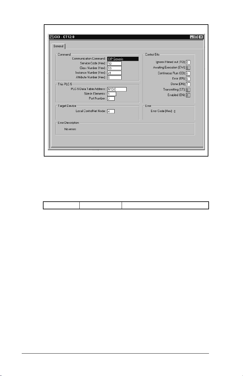
.
Figure 6.12 – CIO Set Attribute Single Screen
Set Attribute Single example request (writing SP600 parameter 41
in figure 6.12):
Request Data
6-18
N13:0 2300 Value = 230.0 VAC
ControlNet Communications Module
Page 69

C
HAPTER
7
ControlLogix Applications
Chapter 7 provides information and examples that explain how to
use I/O Messaging and Explicit Messaging to control, configure, and
monitor an SP600 drive using a ControlNet scanner module.
ATTENTION:
intended solely for purpose of example. There are
!
Refer to chapter 6 for further information on I/O Image layout and
using Logic Command/Status, Reference/Feedback and Datalinks.
many variables and requirements with any
application. Rockwell Automation does not assume
responsibility or liability (to include intellectual
property liability) for actual use of the examples
shown in this publication. Failure to observe this
precaution could result in bodily injury or damage to
equipment.
ATTENTION:
to write parameter data to Non-Volatile Storage
(NVS) frequently, the NVS will quickly exceed its life
cycle and cause the drive to malfunction. Do not
create a program that frequently uses Explicit
Messages to write parameter data to NVS. Datalinks
do not write to NVS and should be used for frequently
changed parameters. Failure to observe this
precaution could result in damage to, or destruction
of, the equipment.
The examples in this publication are
If Explicit Messages are programmed
ControlLogix Applications
7-1
Page 70
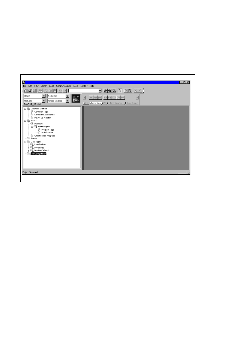
7.1 Configuring a ControlLogix CNB Scanner
Configuring a ControlLogix CNB scanner, and the network, is
mainly done using RSLogix 5000 software (figure 7.1). RSNetWorx
is still required, but only at the end of the configuration process.
Start the RSLogix 5000 software to begin the configuration process.
RSLogix 5000 - Example_RECOMM-C NE T[1756-L1]
_
RECOMM-CNET
Figure 7.1 – RSLogix 5000: I/O Configuration Selection
7-2
Step 1. Right-click on the
New Module
(figure 7.2).
I/O Configuration
ControlNet Communications Module
folder and select
Page 71

RSLogix 5000 - Example_RECOMM-CNET[1756/L1]
_RECOMM-CNET
Figure 7.2 – RSLogix 5000: New Module Selection
Step 2. Select the ControlNet module used by the controller. In
this example (figure 7.3), a 1756-CNB Series B
ControlNet Bridge is selected. Click OK.
Figure 7.3 – Select Module Type: 1756-CNB/B Selection
ControlLogix Applications
7-3
Page 72

Step 3. Enter a
(figure 7.4). Click
Figure 7.4 – Module Properties: Name Selection
Nam
e, Slot
Next>
number, and
.
Revision
number
Step 4. This step is used to define controller-to-module behavior
(figure 7.5).
nhibit Module
I
connection to the module. The
inhibits/un-inhibits the
ajor Fault
M
check-box
selects if a failure on the connection of this module
causes a major fault on the controller if the connection for
the module fails. Click
Next
>.
Figure 7.5 – Module Properties: Controller-to-Module Behavior Screen
7-4
ControlNet Communications Module
Page 73

Step 5. This window (figure 7.6) is displayed for informational
purposes only. Click
Figure 7.6 – Module Properties: Indentification/Status Screen
Next>
.
Step 6. This window (figure 7.7) is displayed for informational
purposes only. Click
Figure 7.7 – Module Properties: Informational Screen
Finish>>
.
ControlLogix Applications
7-5
Page 74

Step 7. The 1756-CNB/B now appears in the I/O Configuration
folder (figure 7.8).
RSLogix 5000 - Example_RECOMM-CNET[1756-L1]
_RECOMM-CNET
Figure 7.8 – RSLogix 5000: I/O Configuration Folder
7-6
ControlNet Communications Module
Page 75

Step 8. Right-click on the 1756-CNB and select
(figure 7.9).
RSLogix 5000 - Example_RECOMM-CNET[1756-L1]
_RECOMM-CNET
Figure 7.9 – RSLogix 5000: New Module Selection Screen
New Module
ControlLogix Applications
7-7
Page 76

Step 9. To configure a RECOMM-CNET ControlNet module,
select the
CONTROLNET-MODULE
type (figure 7.10).
Click OK.
Figure 7.10 – Select Module Type: Generic ControlNet Module Screen
7-8
Step 10. Enter the
7.11). The
e, Description
Nam
Comm F
ormat
and
Node
selects the communication
format for the module and must be set to
Instance is the input connection point for the primary
connection.
O
point for the primary connection.
Instance is the output connection
utput
C
onfiguration
is the size of the configuration assembly. The values
entered will vary based on your application needs and the
size (16- or 32-bit) of the Reference/Feedback and
Datalinks in the drive. For example:
SP600 (16-Bit Ref/Fdbk and Datalinks)
Node configured for: Input Size Output Size
Logic Command / Reference and
42
Logic Status / Feedback only
plus Datalink A 6 4
plus Datalink B 8 6
plus Datalink C 10 8
plus Datalink D 12 10
ControlNet Communications Module
number (figure
Data-INT. I
nput
Instance
Page 77

SP600_02
Figure 7.11 – Module Properties: ControlNet Module Parameters
Step 11. The
connection to move data to or from the module at least
this often or the connection will fail with the RPI Not Valid
error. Set this value to 5 ms or greater, and click
(figure 7.12).
Important:
The RPI time must be set greater than or equal to the
Network Update Time (NUT).
Figure 7.12 – Module Properties: RPI Selection
R
equested Packet Interval (RPI)
schedules the
Next>
ControlLogix Applications
7-9
Page 78
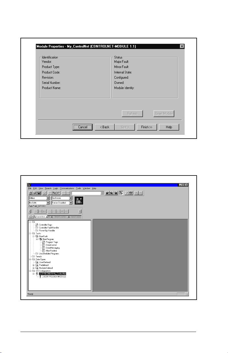
Step 12. This window (figure 7.13) is for informational purposes
only. Click
Figure 7.13 – Module Properties: My ControlNet
Finish>>
.
Step 13. The configured node (“SP600_02” in this example) now
appears under the 1756-CNB module in the I/O
Configuration folder.
RSLogix 5000 - Example_RECOMM-CNET [1756-L1]
Controller Example_RECO MM-CNET
SP600_02
Figure 7.14 – RSLogix: Configure Additional Nodes Screen
Step 14. Repeat the previous steps for each additional node you
need to configure.
7-10
ControlNet Communications Module
Page 79

Step 15. In the
Data Types
sub-folder. When you create a module, module-defined
data types and tags are automatically created. These tags
allow you to access the Input and Output Data of the
module via the controller’s ladder logic.
RSLogix 5000 - Example_RECOMM-CNET [1756-L1]
Controller Example_RECO MM-CNET
RE:
RE:
RE:
SP600_02
Figure 7.15 – RSLogix 5000: Module-Defined Screen
folder, click on the
Module-Defined
Step 16. Select
configuration to the controller (figure 7.16). RSLogix
automatically enters on-line mode when complete.
Figure 7.16 – Download to the Controller Dialong Box
ControlLogix Applications
Communications
Example_RECOMM-CNET
/ Download
to download the
7-11
Page 80

Step 17. An Attention symbol is located next to the Node 2
(SP600_02) icon in figure 7.17, which indicates the
ControlNet scanner needs to be configured.
RSLogix 5000 - Example_RECOMM-CNET [1756-L1]
Controller Example - RECOMM-CNET
RE:
RE:
RE:
SP600_02
Figure 7.17 – RSLogix: Attention Symbol
7-12
Step 18. Start RSNetWorx and perform the following:
a. Click the On-line icon and browse the network.
b. Select Edits Enabled and view the messages in the
Message View for completion (figure 7.18). The
con should disappear from the nodes in the Graphical
i
View.
c. Select
F
ile / Save
and save the project (figure 7.19).
d. Close RSNetworx.
This schedules the I/O that was configured in
RLSLogix 5000.
ControlNet Communications Module
Page 81

SP600
Figure 7.18 – RSNetWorx for ControlNet Screen
ControlLogix Applications
7-13
Page 82

SP600
Figure 7.19 – RSLogix 5000: Example Without Attention Symbol
7-14
ControlNet Communications Module
Page 83

Step 19. The Attention symbol on the RSLogix 5000 connection
tree will disappear if the network has been configured
properly (figure 7.20). You are now ready to develop your
ladder logic program.
RSLogix 5000 - Example_RECOMM-CNET [1756-L1]
Controller Example_RECOMM-CNET
RE:
RE:
RE:
SP600
Figure 7.20 – RSLogix 5000: Connection Tree Without Attention Symbol
7.2 Function of the Sample Program
The program performs the following actions:
Obtains Logic Status information from the drive.
•
Uses the Logic Command to control the drive (for example, start,
•
stop).
Sends a Reference to the drive and receives Feedback from the
•
drive.
Sends/Receives Datalink data to/from the drive.
•
Module Settings For Use With the Example
Nodes 2 and 3.
ControlLogix Applications
7-15
Page 84

Parameter Settings for the Sample Program
Table 7.1 – Parameter Settings for the Sample Program
Device Parameter Name Value Description
90 Speed Ref A Sel 22 ‘Network’ (RECOMM-CNET)
300 Data In A1 140 Points to 140 (Accel Time 1)
301 Data In A2 142 Points to 142 (Decel Time 1)
302 Data In B1 100 Points to 100 (Jog Speed)
SP600 Drive
RECOMM-CNET
303 Data In B2 155 Points to 155 (Stop Mode A)
310 Data Out A1 140 Points to 140 (Accel Time 1)
311 Data Out A2 142 Points to 142 (Decel Time 1)
312 Data Out B1 100 Points to 100 (Jog Speed)
313 Data Out B2 155 Points to 155 (Stop Mode A)
13 DPI I/O Cfg xxx1 1111 Enables Cmd/Ref, Datalinks A-D
25 M-S Input xxx1 1111 Configures the I/O Data to be
26 M-S Output xxx1 1111 Configures the I/O Data to be
transferred from the network to the
drive.
transferred from the drive to the
network.
Logic Command/Status Words
These examples use the Logic Command word and Logic Status
word for SP600 drives. Refer to Appendix D, Logic Command/
Status Words to view these. The definition of the bits in these words
may vary if you are using a different DPI product. Refer to the
documentation for your drive.
7-16
ControlNet Communications Module
Page 85

7.3 RSLogix 5000 Ladder Logic Program
This rung determines whether the drive is running, and sets the DriveStatusRunning tag appropriately.
This rung determines whether the drive is running, and sets the DriveStatusRunning tag appropriately.
DriveInputImage.Data[2].1
<SP600
<PowerFlex70_02:I.Data[2].1>
This rung determines whether the drive is faulted, and sets the DriveStatusFaulted tag appropriately.
This rung determines whether the drive is faulted, and sets the DriveStatusFaulted tag appropriately.
DriveInputImage.Data[2].7
<PowerFlex70_02:I.Data[2].7>
This rung moves the drive's frequency feedback to the DriveFeedback tag.
This rung moves the drive's frequency feedback to the DriveFeedback tag.
When the DriveCommandStart tag is true, this rung sends a start command to the drive.
When the DriveCommandStart tag is true, this rung sends a start command to the drive.
DriveCommandStart
When the DriveCommandNotStop tag is false, this rung sends a stop command to the drive. This rung uses an
When the DriveCommandNotStop tag is false, this rung sends a stop command to the drive. This rung uses an
XIO input instruction because Stop pushbuttons are usually normally closed so that the equipment stops if a wire
XIO input instruction because Stop pushbuttons are usually normally closed so that the equipment stops if a wire
breaks.
breaks.
DriveCommandNotStop
<SP600_
Copy File
Source DriveInputImage.Data[3]
<PowerFlex70_02:I.Data[3]>
Dest DriveFeedback
Length 1
/
DriveStatusRunning
DriveStatusFaulted
COP
<SP600_
DriveOutputImage.Data[0].1
<SP600_
<PowerFlex70_02:O.Data[0].1>
DriveOutputImage.Data[0].0
<PowerFlex70_02:O.Data[0].0>
<SP600_
When the DriveCommandJog tag is true, this rung sends a jog command to the drive.
When the DriveCommandJog tag is true, this rung sends a jog command to the drive.
DriveCommandJog
When the DriveCommandClearFault tag is true, this rung sends a clear fault command to the drive.
When the DriveCommandClearFault tag is true, this rung sends a clear fault command to the drive.
DriveCommandClearFault
Figure 7.21 – I/O Messaging
ControlLogix Applications
DriveOutputImage.Data[0].2
<SP600_
<PowerFlex70_02:O.Data[0].2>
DriveOutputImage.Data[0].3
<PowerFlex70_02:O.Data[0].3>
<SP600_
7-17
Page 86

This rung moves data from the DriveReference tag to the drive where it is used as a frequency reference.
This rung moves data from the DriveReference tag to the drive where it is used as a frequency reference.
7 Copy File
This rung moves Datalink data from the drive.
This rung moves Datalink data from the drive.
8 Copy File
This rung moves Datalink data to the drive.
This rung moves Datalink data to the drive.
9 Copy File
(End)
Source DriveInputImage.Data[4]
Dest ParameterDataFromDrive[0]
Length 8
Source ParameterDataToDrive[0]
Dest DriveOutputImage.Data[2]
Length 8
Figure 7.22 – I/O Messaging (Continued)
COP
Source DriveReference
Dest DriveOutputImage.Data[1]
<SP600_
<PowerFlex70_02:O.Data[1]>
Length 1
COP
<SP600_
<PowerFlex70_02:I.Data[4]>
COP
<SP600_
<PowerFlex70_02:O.Data[2]>
7-18
ControlNet Communications Module
Page 87
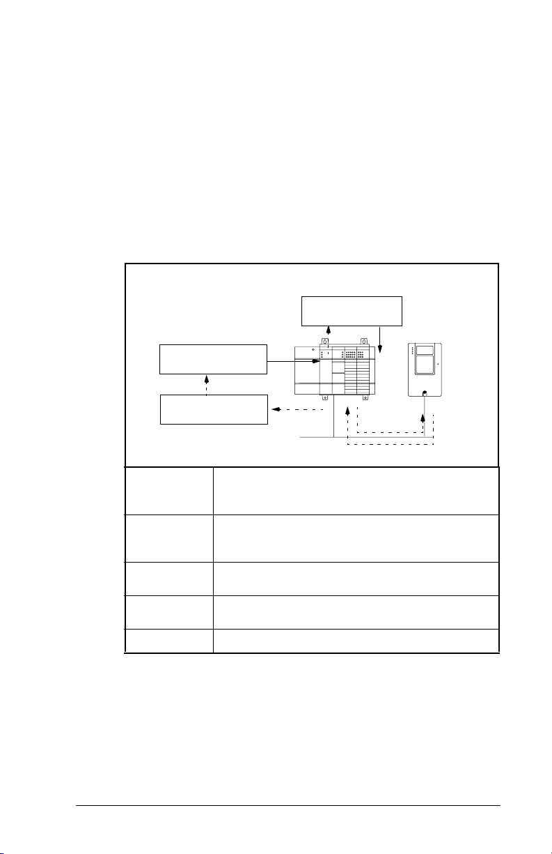
7.4 About Explicit Messaging
Explicit Messaging is used to transfer data that does not require
continuous updates. With Explicit Messaging, you can configure
and monitor a slave device’s parameters on the ControlNet network.
7.4.1 Performing Explicit Messages
Important:
➎
Complete Parameter
Message
➍
Retrieve Parameter
Message Response
➊
➋
➌
➍
➎
There are five basic events in the Explicit Messaging
process defined below. The details of each step will
vary depending on the controller. Refer to the
documentation for your controller.
➊
Set up and send
Parameter M es sa g e
➋
➌
Format the required data and set up the ladder
logic program to send an Explicit Message
request to the scanner module (download).
The scanner module transmits the Explicit
Message Request to the slave device over the
ControlNet network.
The slave device transmits the Explicit Message
Response back to the master.
The controller retrieves the Explicit Message
Response.
The Explicit Message is complete.
Figure 7.23 – Explicit Message Process
Important:
ControlLogix Applications
The scanner module may be integrated with the
controller (e.g., PLC-5C).
7-19
Page 88

7.4.2 Explicit Messaging Examples
This rung sends a C IP message to the SP600 drive at Control N et Address 2. The data sent is obtained
This rung sends a CIP message to the PowerFlex 70 drive at ControlNet address 2. The data sent is obtained
This rung sends a CIP message to the PowerFlex 70 drive at ControlNet address 2. The data sent is obtained
from the MessageSendData tag. The data received is stored in the MessageReplyData tag. This MSG instruction
from the MessageSendData tag. The data received is stored in the MessageReplyData tag. This MSG instruction
can be configured to send any CIP message.
can be configured to send any CIP message.
EnableDriveMessage
0
(End)
Type - CIP Generic
Message Control DriveMessageControl
Figure 7.24 – Explicit Messaging
A Get_Attributes_Scattered message allows for reading multiple
parameters that may or may not be in sequential order (figure 7.25).
A Service Code of “4B” indicates the Get_Attributes_Scattered
•
service (see page C-20, Object Specific Services).
A Class Number of “93” indicates accessing the DPI Parameter
•
Object (see page C-16, DPI Parameter Object).
An Instance Number of “0” is the Class Attributes for the drive
•
(see page C-16, Instances).
The Source identifies the service data with the request message
•
to send.
The Destination contains the response message to the request.
•
MSG
EN
DN
...
ER
7-20
ControlNet Communications Module
Page 89

Figure 7.25 – Get_Attributes_Scattered Message Screen
Get Attributes Scattered sample request and response data:
(Source) Request Data
0 12 Parameter Number = 12
1 0 (Pad Word)
2 0 (Pad Word)
3 11 Parameter Number = 11
4 0 (Pad Word)
5 0 (Pad Word)
6 10 Parameter Number = 10
7 0 (Pad Word)
8 0 (Pad Word)
9 9 Parameter Number = 9
10 0 (Pad Word)
11 0 (Pad Word)
ControlLogix Applications
7-21
Page 90
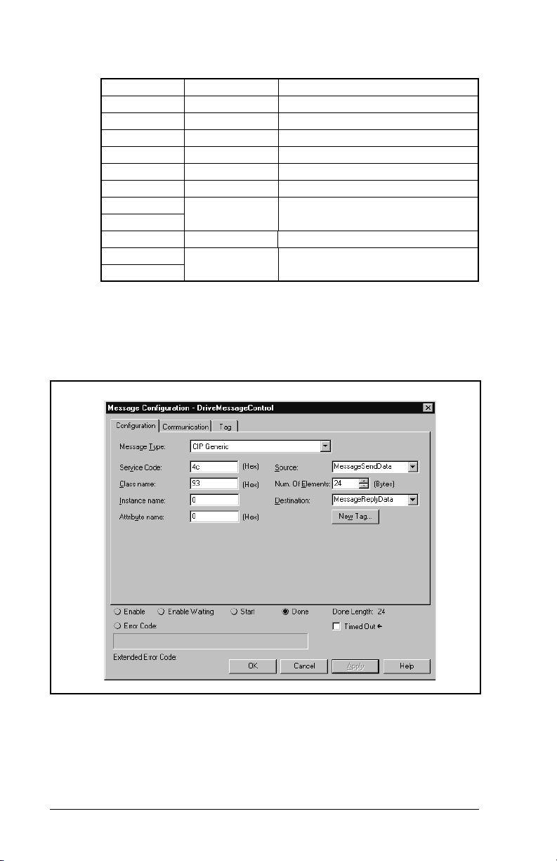
(Destination) Response Data
0 12 Parameter Number = 12
1 3333 Value = 333.3VDC
2 0 (Pad Word)
3 11 Parameter Number = 11
4 0 Value = 0.0Hz
5 0 (Pad Word)
6 10 Parameter Number = 10
7 148 Value = 14.8Hrs
8
9 9 Parameter Number = 9
10 23 Value = 2.3MWh
11
A Set _Attributes_Scattered message is used to write multiple
parameters that may or may not be in sequential order (figure 7.26).
A Service Code of “4C” indicates the Set_Attributes_Scattered
service (see page C-20, Object Specific Services).
7-22
Figure 7.26 – Set_Attributes_Scattered Message Screen
ControlNet Communications Module
Page 91

Set_Attributes_Scattered sample request and response data:
(Source) Request Data
N13:0 45 Parameter Number = 45
N13:1 50 Value = 0.50HP
N13:2 0 (Pad Word)
N13:3 44 Parameter Number = 44
N13:4 1740 Value = 1740RPM
N13:5 0 (Pad Word)
N13:6 43 Parameter Number = 43
N13:7 600 Value = 60.0Hz
N13:8 0 (Pad Word)
N13:9 42 Parameter Number = 42
N13:10 16 Value = 1.6Amps
N13:11 0 (Pad Word)
(Destination) Response Data
N14:0 45 Parameter Number = 45
N14:1 0 (Pad Word)
N14:2 0 (Pad Word)
N14:3 44 Parameter Number = 44
N14:4 0 (Pad Word)
N14:5 0 (Pad Word)
N14:6 43 Parameter Number = 43
N14:7 0 (Pad Word)
N14:8 0 (Pad Word)
N14:9 42 Parameter Number = 42
N14:10 0 (Pad Word)
N14:11 0 (Pad Word)
A Set_Attribute_Single message is used to write a single parameter
(figure 7.27).
A Service Code of “10” indicates the Set_Attribute_Single service
•
(see page C-8, Services).
A Class Name of “F” indicates the Parameter Object (see page
•
C-6, Parameter Object).
An Instance of “45” indicates the Drive Parameter 45 Attributes
•
(see page C-6, Instances).
An Attribute of “1” indicates the Parameter Value (see page C-7,
•
Instance Attributes).
ControlLogix Applications
7-23
Page 92

.
Figure 7.27 – Set_Attribute_Single Message Screen
Set_Attribute_Single example (writing SP600 Parameter 45 in figure
7.27 ):
7-24
Send Data
0 50 Value = 0.50HP
A Get_Attribute_Single message is used to read a single parameter
(figure 7.28).
A Service Code of “E” indicates the Get_Attribute_Single service
•
(see page C-8, Services).
A Class Name of “F” indicates the Parameter Object (see page
•
C-6, Parameter Object).
An Instance of “45” indicates the Drive Parameter 45 Attributes
•
(see page C-6, Instances).
An Attribute of “1” indicates the Parameter Value (see page C-7,
•
Instance Attributes).
ControlNet Communications Module
Page 93

Figure 7.28 – Get_Attributes_Single Message Screen
Get Attributes Single example (reading S600 Parameter 45 in figure
7.28):
Reply Data
0 50 Value = 0.50HP
ControlLogix Applications
7-25
Page 94

ControlLogix Applications
7-26
Page 95
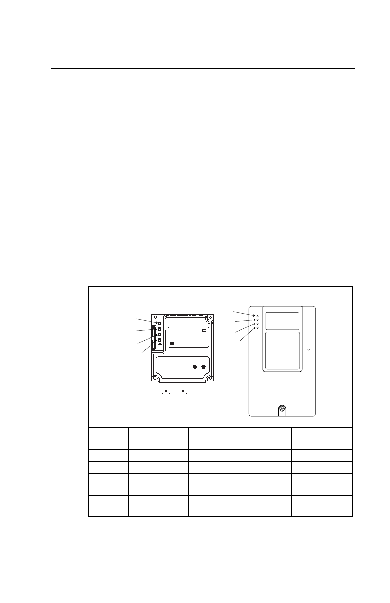
C
HAPTER
8
Troubleshooting the
ControlNet Module
and Network
Chapter 8 contains information for troubleshooting the ControlNet
module and the network.
8.1 Understanding the Status Indicators
The ControlNet module has four status indicators. They can be
viewed on the module or through the drive cover. (See figure 8.1.)
➀
➁
➀
➁
➂
➂
➃
Status
Number
➀
➁
➂
➃
Troubleshooting the ControlNet Module and Network
Indicator Description Refer to...
DRIVE DPI Connection Status Section 8.1.1
MS Module Status Section 8.1.2
NET A ControlNet A Status Sections 8.1.3
NET B ControlNet B Status Sections 8.1.3
Figure 8.1 – Status Indicators (Location on Drive May Vary)
➃
and 8.1.4
and 8.1.4
8-1
Page 96

8.1.1 DRIVE Status Indicator
Table 8.1 – DRIVE Status Indicator: State Definitions
Status Cause Corrective Action
Off The module is not
Flashing
Red
Solid
Red
Orange The module is
Flashing
Green
Solid
Green
powered or is not
connected properly to
the drive.
The module is not
receiving a ping
message from the
drive.
The drive has refused
an I/O connection from
the module.
Another DPI peripheral
is using the same DPI
port as the module.
connected to a product
that does not support
Reliance Electric DPI
communications.
The module is
establishing an I/O
connection to the drive.
The module is properly
connected and is
communicating with the
drive.
Securely connect the module
•
to the drive using the ribbon
cable.
Apply power to the drive.
•
Verify that cables are
•
securely connected.
Cycle power to the drive.
•
Important:
product after making any of the
following corrections:
Verify that all DPI cables are
•
securely connected and not
damaged. Replace cables if
necessary.
Verify that the DPI Host
•
supports Datalinks.
Configure the module and
•
DPI Host to use a Datalink
that is not already being
used by another peripheral.
Connect the module to a
•
product that supports
Reliance Electric DPI
communications (for
example, SP600 drives).
No action. Normal behavior if
•
no DPI I/O is enabled.
No action.
•
Cycle power to the
8-2
ControlNet Communications Module
Page 97

8.1.2 MS Status Indicator
Table 8.2 – MS Status Indicator: State Definitions
Status Cause Corrective Action
Off The module is not
Flashing
Red
Solid
Red
Flashing
Green
Solid
Green
powered.
The module has
failed the firmware
test.
The module has
failed the hardware
test.
The module is
operational but is not
transferring I/O data.
The module is
operational and
transferring I/O data.
Securely connect the module
•
to the SP600 drive using the
ribbon cable.
Apply power to the drive and
•
network.
Cycle power to the drive.
•
Parameter settings may have
been changed.
Clear faults in the module.
•
If cycling power does not
•
correct the problem, the
parameter settings may have
been corrupted. Reset defaults
and reconfigure the module.
If resetting defaults does not
•
correct the problem, flash the
module with the latest firmware
release.
Cycle power to the drive.
•
Replace the module.
•
Place the scanner in RUN
•
mode.
Program the controller to
•
recognize and transmit I/O to
the module.
Configure the module for the
•
program in the controller.
Normal behavior if no DPI I/O
•
is enabled.
No action.
•
Troubleshooting the ControlNet Module and Network
8-3
Page 98

8.1.3 NET A and B Together
Table 8.3 – NET A and B Together: State Definitions
Status Cause Corrective Actions
Both LEDs
are off
Both LEDs
are steady
red
LEDs are
alternating
red/green
LEDs are
alternating
red/off
A reset occurred or
there is no power.
A link interface
failed.
The module is in
self-test mode.
There is a bad
configuration.
Apply power to the module.
•
Check media for broken cables,
•
loose connectors, missing
terminators, etc.
Power cycle or reset the
•
module. If the problem persists,
contact Rockwell Automation
support.
No action required. The module
•
will exit this mode when the
self-test is completed.
Verify that all node addresses
•
are unique.
Check the module’s
•
configuration.
Check media for broken cables,
•
loose connectors, missing
terminators, etc.
Power cycle or reset the
•
module.
8-4
ControlNet Communications Module
Page 99

8.1.4 NET A and B Independently
Table 8.4 – NET A and B Independently: State Definitions
Status Cause Corrective Actions
One
channel
LED is
steady off
One
channel
LED is
flashing
red/green
One
channel
LED is
flashing
red/off
One
channel
LED is
flashing
green/off
One
channel
LED is
steady
green
That channel is
disabled or not
supported.
There is an invalid
link configuration
for that channel.
The channel is not
receiving network
activity.
A temporary
channel error has
occurred, or the
channel is in listenonly mode.
Normal operation
for that channel.
Program the network for
•
redundant media, if required.
Power cycle or reset the
•
module.
Reset the controller.
•
If the problem persists, contact
•
Rockwell Automation support.
Check media for broken calbes,
•
loose connectors, missing
terminators, etc.
Verify the controller is present
•
on the network and working.
No action required.
•
Troubleshooting the ControlNet Module and Network
8-5
Page 100

8.2 Module Diagnostic Items
Table 8.5 lists diagnostic items that can be accessed using
VS Utilities software or the LCD OIM.
Table 8.5 – Module Diagnostic Items
No. Event Description
1 Common Logic
Cmd
2 Prod Logic Cmd The current value of the Product-Specific Logic
3 Reference The current value of the Product-Specific
4 Common Logic Sts The current value of the Common Logic Status
5 Prod Logic Sts The current value of the Product-Specific Status
6 Feedback The current value of the Product-Specific
7 Datalink A1 In The current value of Datalink A1 being
8 Datalink A2 In The current value of Datalink A2 being
9 Datalink B1 In The current value of Datalink B1 being
10 Datalink B2 In The current value of Datalink B2 being
11 Datalink C1 In The current value of Datalink C1 being
12 Datalink C2 In The current value of Datalink C2 being
13 Datalink D1 In The current value of Datalink D1 being
14 Datalink D2 In The current value of Datalink D2 being
15 Datalink A1 Out The current value of Datalink A1 being received
16 Datalink A2 Out The current value of Datalink A2 being received
The current value of the Common Logic
Command being transmitted to the host.
Command being transmitted to the host.
Reference being transmitted to the host.
being received from the host.
being received from the host.
Feedback being received from the host.
transmitted to the host. (Value of 0 if datalink is
not used).
transmitted to the host. (Value of 0 if datalink is
not used).
transmitted to the host. (Value of 0 if Datalink is
not used).
transmitted to the host. (Value of 0 if Datalink is
not used).
transmitted to the host. (Value of 0 if Datalink not
used).
transmitted to the host. (Value of 0 if Datalink is
not used).
transmitted to the host. (Value of 0 if Datalink is
not used).
transmitted to the host. (Value of 0 if Datalink is
not used).
from the host.
from the host.
8-6
ControlNet Communications Module
 Loading...