

Page 1

RS485 DF1
Communications Module
M/N RECOMM-485
Instruction Manual
D2-3514
Page 2
The information in this manual is subject to change without notice.
Trademarks not belonging to Rockwell Automation are property of their respective companies.
Throughout this manual, the following notes are used to alert you to safety
considerations:
ATTENTION: Identifi es informat ion about practices or
circumstances that can lead to personal injury or death, property
damage, or economi c loss.
!
Important: Identifies information th at i s c riti cal for s uc cess ful a ppl ic ati on and
understanding of the product.
ATTENTION: The drive ma y contain hig h voltages t hat can cause
injury or death. Remove all power from the drive, and then verify
power has been removed before installing or removing an RS485
!
DF1 module. Failure to observe these precautions could result in
severe bodily injury or loss of life.
ATTENTION: Only qualified electrical personnel familiar with
drive and power products an d the associated machinery sho ul d
plan or implement the install at ion, start u p, conf i gu ration, and
subsequent mainten ance of the product using an RS 485 DF1
module. Read and und er stand th is manual in its entirety before
proceeding. Failure to observe these precautions could result
bodily injury and/or damage to equipment.
ATTENTION: DPI host prod uct s mus t no t be dir ec t l y con ne ct ed
together via RECBL-xxx cables. Unpredictable behavior due to
timing and other internal procedures can result if two or more
devices are connect ed in this manner. Failure to observe this
precaution could result in bo di ly in jury and/or damage to
equipment.
ATTENTION: If the RS485 DF1 module is transmitting control
I/O to the drive, the drive ma y fa ul t when you reset the module.
Determine h ow your dr ive will respond b efore res etting a mo dule.
Failure to observe this pre caution could result bodily inju ry
and/or damage to equipment.
ATTENTION: Comm Flt Acti on (paramete r 10) lets you de termine
the action of the module and connected drive if communications
are disrupted. By default, this parameter faults the drive. You can
set this p ara meter so that the d rive co ntin ues t o run. Preca ution s
should be taken to ensure that the setting of this parameter does
not create a hazard of injury or equipment damage. When
commissioning the dr ive, verify that your system responds
correctly to various situations (for example, a disconnected cable
or a faulted controller). F ailu re to observe this precaution co ul d
result bodily injury and/o r da m age to equipment.
ATTENTION: When a system is configured for the first time, there
may be unintended or incorrect machine motion. Disconnect the
motor from the machine or process during initial system test i ng.
Failure to observe this precaution could result in bodily injury
and/or damage to equipment.
Windows is a trademar k of Microsoft Corporation.
Reliance, SP600, VS Utilities, and DPI are trademarks of Rockwell Autom ation.
©2002 Rockwell Automation. All rights reserved.
Page 3

CONTENTS
Chapter 1 Introduction
1.1 Module Features.......................................... ..... ...... ...... .1-1
1.2 Related Documentation.................................................1-2
1.3 Getting Assistance from Reliance Electric..................... 1-2
Chapter 2 Getting Started
2.1 Required Equipment......................................................2-2
2.2 Installation Checklist ......................................................2-3
Chapter 3 Installing the RS485 DF1 Module
3.1 Preparing for an Installation...........................................3-1
3.2 Commissioning the Module ........................................... 3-1
3.3 Connecting the Module to the Drive ..............................3-3
3.4 Connecting the Module to the Network.......................... 3-6
3.5 Applying Power.............................................................. 3-7
Chapter 4 Configuring the RS485 DF1 Module
4.1 Configuration Tools........................................................ 4-1
4.2 Using the LCD OIM to Configure the Module................ 4-2
4.3 Setting the Node Address.............................................. 4-2
4.4 Setting the Data Rate....................................................4-3
4.5 Setting the Error-Checking Method ...............................4-3
4.6 Setting the I/O Configuration .........................................4-4
4.7 Setting a Fault Action..................................................... 4-5
4.7.1 Setting the Fault Configuration Parameters........4-6
4.7.2 Resetting the Module........................................... 4-6
4.8 Viewing the Module Configuration.................................4-8
Chapter 5 Using VS Utilities on the RS485 Network
Chapter 6 Troubleshooting the Module and Network
6.1 Understanding the Status Indicators..............................6-1
6.1.1 DRIVE Status Indicator........................................6-2
6.1.2 MS Status Indicator.............................................6-3
6.1.3 NET A Status Indicator........................................ 6-4
6.1.4 NET B Status Indicator........................................ 6-5
6.2 Module Diagnostic Items....................... ...... .................. 6-5
6.3 Viewing and Clearing Events......................................... 6-7
Contents
I
Page 4

Appendix A Technical Specifications...................................................... A-1
Appendix B RS485 DF1 Module Parameters ..........................................B-1
Appendix C Logic Command/Status Words.............................................C-1
Glossary ..................................................................................Glossary-1
Index .......................................................................................Index-1
II
RS485 DF1 Communications Module
Page 5

List of Figures
Figure 2.1 – Components of the RS485 DF1 Module................................. 2-1
Figure 3.1 – Setting the Module’s Node Address....................................... 3-2
Figure 3.2 – Setting the Data Rate.............................................................3-2
Figure 3.3 – DPI Ports and Internal Interface Cables................................. 3-4
Figure 3.4 – Mounting the Module.............................................................. 3-5
Figure 3.5 – Typical Network Connections................................................. 3-6
Figure 4.1 – Accessing the Module Parameters using the LCD OIM.........4-2
Figure 4.2 – RS485 DF1 Node Address Screen on an LCD OIM............... 4-2
Figure 4.3 – Data Rate Screen on an LCD OIM.........................................4-3
Figure 4.4 – Error-Checking Method Screen on an LCD OIM.................... 4-3
Figure 4.5 – I/O Configuration Screen on an LCD OIM.............................. 4-4
Figure 4.6 – Fault Action Screen on an LCD OIM...................................... 4-5
Figure 4.7 – Reset Screen on an LCD OIM................................................ 4-7
Figure 5.1 – Typical RS485 DF1 Network.................................................. 5-1
Figure 5.2 – Connecting to the Network.....................................................5-1
Figure 5.3 – Node Selection Screen: Multiple Nodes Selected.................. 5-2
Figure 5.4 – Results of Search of Selected Nodes.....................................5-2
Figure 5.5 – Result of Device Read Performed by VS Utilities...................5-3
Figure 5.6 – Expanding Each Node............................................................ 5-3
Figure 5.7 – Accessing the Parameters in the Selected Device................. 5-4
Figure 6.1 – Status Indicators (Location on Drive May Vary)..................... 6-1
Figure 6.2 – Viewing and Clearing Events Using an LCD OIM...................6-7
Contents
III
Page 6

IV
RS485 DF1 Communications Module
Page 7

List of Tables
Table 2.1 – Equipment Shipped with the RS485 DF1 Module....................2-2
Table 2.2 – Required User-Supplied Equipment........................................2-2
Table 4.1 – Configuration Tools..................................................................4-1
Table 4.2 – Selections for Drive Response to Communication Fault..........4-5
Table 4.3 – Fault Configuration Parameters...............................................4-6
Table 4.4 – Module Configuration Status Parameters................................4-8
Table 6.1 – DRIVE Status Indicator: State Definitions................................6-2
Table 6.2 – MS Status Indicator: State Definitions .....................................6-3
Table 6.3 – NET A Status Indicator: State Definitions................................6-4
Table 6.4 – NET B Status Indicator: State Definitions................................6-5
Table 6.5 – Module Diagnostic Items..........................................................6-5
Table 6.6 – Event Codes and Descriptions.................................................6-8
Contents
V
Page 8

VI
RS485 DF1 Communications Module
Page 9

CHAPTER 1
Introduction
This manual provides information about the RS485 DF1
Communications module (RECOMM-485) and using it with DPI
AC drives, such as SP600 drives. It is intended for qualified
electrical personnel familiar with installing, programming, and
maintaining AC drives and networks.
The RS485 DF1 Communications module allows an RS485 DF1
Master device to access the SP600 drive using:
• Logic Command/Reference (Start, Stop, Reference, etc.)
• Logic Status Feedba ck
• Datalinks A-D
• Explicit Messages
It also allows VS Utilities configuration software (version 1.01 or
higher) to connect to an SP600 drive using a Serial Converter
module (RECOMM-232 ) and co mmun icate with othe r SP600 dri ves
using an RS485 connection.
The module is mounted in the drive an d receive s its required power
from the drive. It can be used with other products that implement
DPI, which is a peripheral communication interface. Refer to the
documentatio n for your prod uct for sp ecific informa tio n about ho w it
works with this module.
1.1 Module Features
The RS485 DF1 Communications module features the following:
• Switches that ena ble y ou to set a no de ad dress and n etwor k dat a
rate before applying power to the drive. Alternatively, you can
disable these switches and use parameters to configure these
features.
• Status indicators that report the status of the drive
communications, module, and network. They are visible both
when the cover is opened and when it is closed.
• I/O, including Logic Command/Reference and up to four pairs of
Datalinks that may be configured for your application using a
parameter.
Introduction
1-1
Page 10

• A number of tools to configure the module and connected drive.
These tools include the LCD OIM and VS Utilities software.
• User-defined fault ac tions that determine how the modu le and the
drive respond to communication disruptions on the network.
1.2 Related Documentation
Refer to the following related publications as necessary for more
information. All of the publications are available from
http://www.theautomationbookstore.com or
http://www.reliance.com.
• D2-3485 SP600 AC Drive User Manual
• D2-3501 SP600 AC Drive User Manual (6SB401Series)
• D2-3488 VS Utilities Getting Results Manual
Online help installed with the software
• 1770-6.5.16 DF1 Protocol and Command Set Reference Manual
1.3 Getting Assistance from Reliance
Electric
If you have any questions or problems with the products described
in this instruction manual, contact your loca l R eli anc e El ectric sales
office.
1-2
For technical assistance, call 1-800-726-8112. Before calling,
please review the trou ble sh ooting section of this ma nua l and check
the Reliance drives website for additional information. When you
call this number, you will be asked for the drive model number and
this instruction manual number.
RS485 DF1 Communications Module
Page 11
CHAPTER 2
Getting Started
This chapter provides:
• A description of the RS485 DF1 module’s components
• A list of parts shipped with the module
• A list of user-supplied parts required for installing the module
• An installation checklist
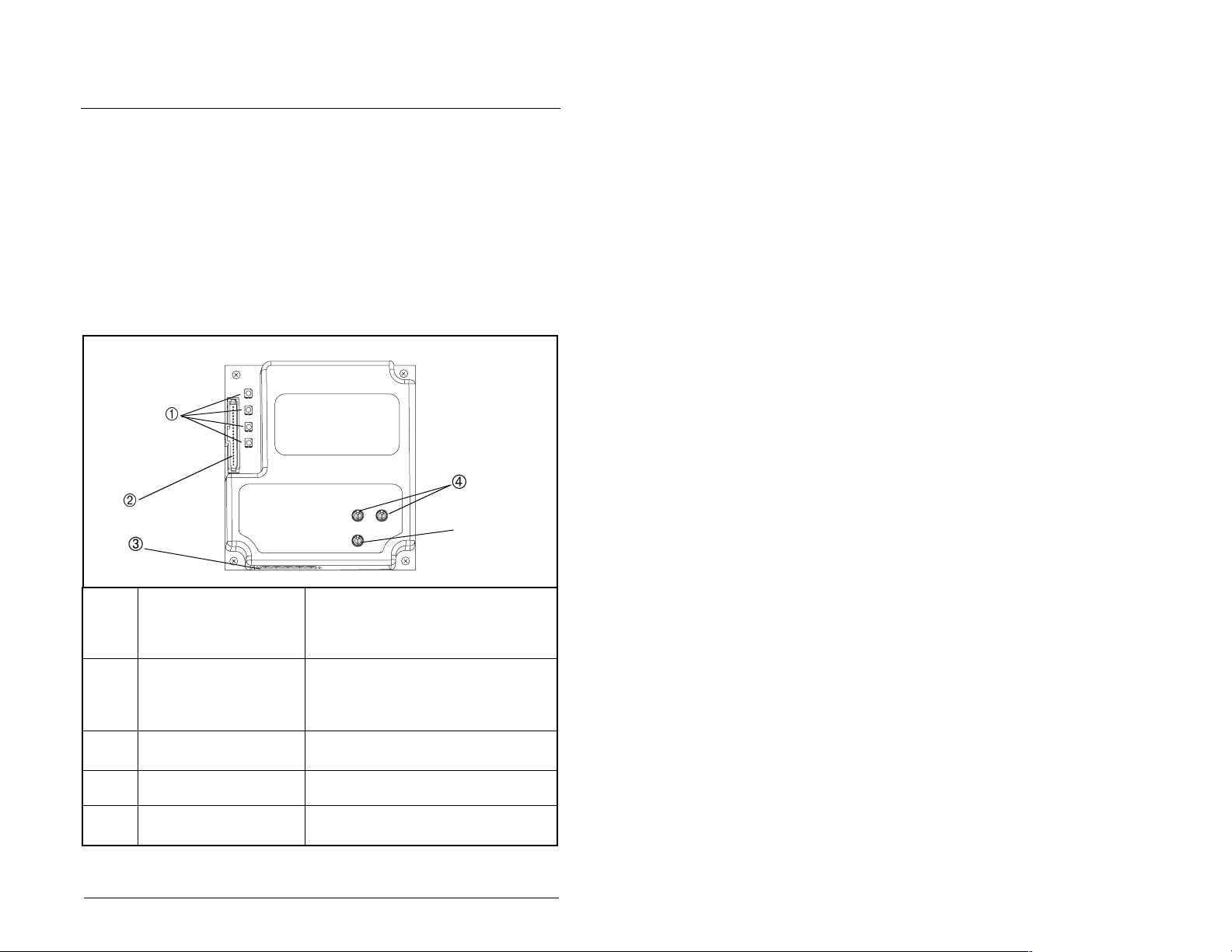
Status Indicators Four LEDs to indicate the status of the
DPI Connector A 20-pin, single-row shrouded male
RS485 DF1 Connector A 6-pin connector to which a 6-pin
Node Address Switches Switches to set the node address.
Data Rate Switch Switch to set the RS485 DF1 dat a rate
Getting Started
connected drive, module, and net work.
Refer to chapter 6 for more information
about the LEDs.
header. An Internal Interface cable
connects to this con ne cto r and one on
the drive.
linear plug can be connected.
at which the module communicates.
Figure 2.1 – Components of the RS485 DF1 Module
2-1
Page 12

2.1 Required Equipment
Table 2.1 lists the equipment shipped with the RS485 DF1 module.
When you unpack the module, verify that the package includes all
of these items.
Table 2.1 – Equipment Shipped with the RS485 DF1 Module
Item Description
One RS485 DF1 Communication Module
One 2.54 cm (1 in) and one 15.24 cm (6 in) Internal Interface
cable (only one of these cables is needed to connect the module
to the drive)
One six-pin linear RS485 DF1 plug (connected to the RS485 DF1
connector on the module)
One grounding wrist strap
One RS485 DF1 Communication Module User Manual (D2-3415)
Table 2.2 lists user-supplied equipment also required to install and
configure the module.
Table 2.2 – Required User-Supplied Equipment
Item Description
Small flathead or Phillips screwdriver
RS485 cable (Belden 3106A or equivalent is recommended)
Configuration tool, such as
• SP600 LCD OIM
• VS Utilities
• with Serial Converter Module (M/N RECOMM-232)
2-2
RS485 DF1 Communication Module
Page 13

2.2 Installation Checklist
This section is designed to help experienced users start using the
RS485 DF1 modu le. If you ar e unsure h ow to compl ete a step , refe r
to the referenced chapter.
✔
Step Action Refer to:
❒
❒
❒
❒
❒
❒
❒
1 Review the safety precautions for the
module.
2 Verify that the drive is properly installed.
3 Commission the module.
Set a unique node address and the
appropriate data rate using the switches on
the module. If desired, you can disable the
switches and use parameter settings
instead.
4 Install the module.
Verify that the drive is not powered. Then,
connect the module to the network using an
RS485 cable and to the drive using the
Internal Interface cable. Use the captive
screws to secure and ground the module to
the drive.
5 Apply power to the module.
Apply power to the drive. (The module
receives power from the drive.) The status
indicators should be green. Refer to chapter
6 for more information if there is a problem.
6 Configure the module for your
application.
Set the parameters for the follo wing fe atures
as required by your application:
• I/O configuration
• Fault actions
7 Apply power to the RS485 DF1 master.
Verify that the master and the network are
installed and functi oni ng in acc ord anc e with
RS485 DF1 standards.
Throughout
this manual
SP600 AC
Drive User
Manual
Chapter 3
Chapter 3
Chapter 3
Chapter 4
Getting Started
2-3
Page 14

2-4
RS485 DF1 Communication Module
Page 15

CHAPTER 3
Installing the
RS485 DF1 Module
Chapter 3 provides instructions for installing the module on an
SP600 drive.
3.1 Preparing for an Installation
Before installing the module, verify that you have all required
equipment. Refer to chapter 2, Getting Started, for a list of
equipment.
3.2 Commissioning the Module
To commiss ion th e modu le, yo u must set a un ique no de address o n
the network, the data rate used by the network, and the errorchecking method. (Refer to the BCC and CRC entries in the
Glossary for more information about these error-checking
methods.)
Important: New settings are recognized only when power is
applied to the module or it is reset. If you change a
setting, cycle power or reset the module.
ATTENTION: The RS485 DF1 module contains
ESD- (Electrostatic Discharge) sensitive parts that
!
Important: To guard a gains t dev ice m alfunc tion, you m ust w ear a
Step 1. Set the module’s node address by rotating the node
Important: Each node on the network must have a unique
Installing the RS485 DF1 Module
can be damaged if you do not follow ESD control
procedures. Static control precautions are required
when handling the mo dule. Failure to o bserve these
precautions could result in damage to equipment.
grounding wrist strap when installing the module.
address switches to the desired value for each digit as
shown in figure 3.1.
address.
3-1
Page 16

2
3
1
0
9
7
8
2
3
4
1
0
5
9
6
4
5
6
7
8
Setting Description
00 to 99 The node address used by the module if switches are
enabled. The default switch setting is 01.
Important: If the Data Rate switch is set to “PGM”
(Program), the module will use the setting of DF1 Addr Cfg
(module parameter 3) for the node address. The default
setting of this parameter is 1. Refer to chapter 4,
Configuring the RS485 DF1 Module, for more information.
Figure 3.1 – Setting the Module’s Node Address
Step 2. Set the Data Rate switch as shown in figure 3.2.
19.2K
9600
4800
2400
1200
38.4K
PGM
Setting Description
1200
The module is set to the respective data rate.
2400
4800
9600
19.2K
38.4K
PGM The module uses the setting of DF1 Rate Cfg (module
parameter 5) for the dat a rate. 9600 is the de fault pa rameter
setting. Refer to chapter 4, Configuring the RS485 DF1
Module for more information.
Figure 3.2 – Setting the Data Rate
3-2
RS485 DF1 Communications Module
Page 17

3.3 Connecting the Module to the Drive
ATTENTION:The SP600 drive may contain high
voltages that can cause injury or death. Remove
!
Step 1. Remove power from the drive.
Step 2. Use static control precautions.
Step 3. Connect the Inte rnal Interfa ce cable to the DPI port o n the
Step 4. For 1-20 HP SP600 drives, fold the Internal Interface
power from the dr ive, and then verify powe r has been
discharged before inst a lli ng or remo vi ng a modu le .
Failure to observe this precaution could result in
severe bodily injury or loss of life.
drive and then to the DPI connector on the module. See
figure 3.3.
cable behind the module and mount the module on the
drive using the four captive screws. See figure 3.4.
For frame 2 and larger SP600 drives, mount the module
on the drive using the four captive screws to secure and
ground it to the drive.
Important: All screws must be tightened since the module is
grounded through a screw. The recommended
tightening torque is 0.9 N-m (8 in-lb).
Installing the RS485 DF1 Module
3-3
Page 18
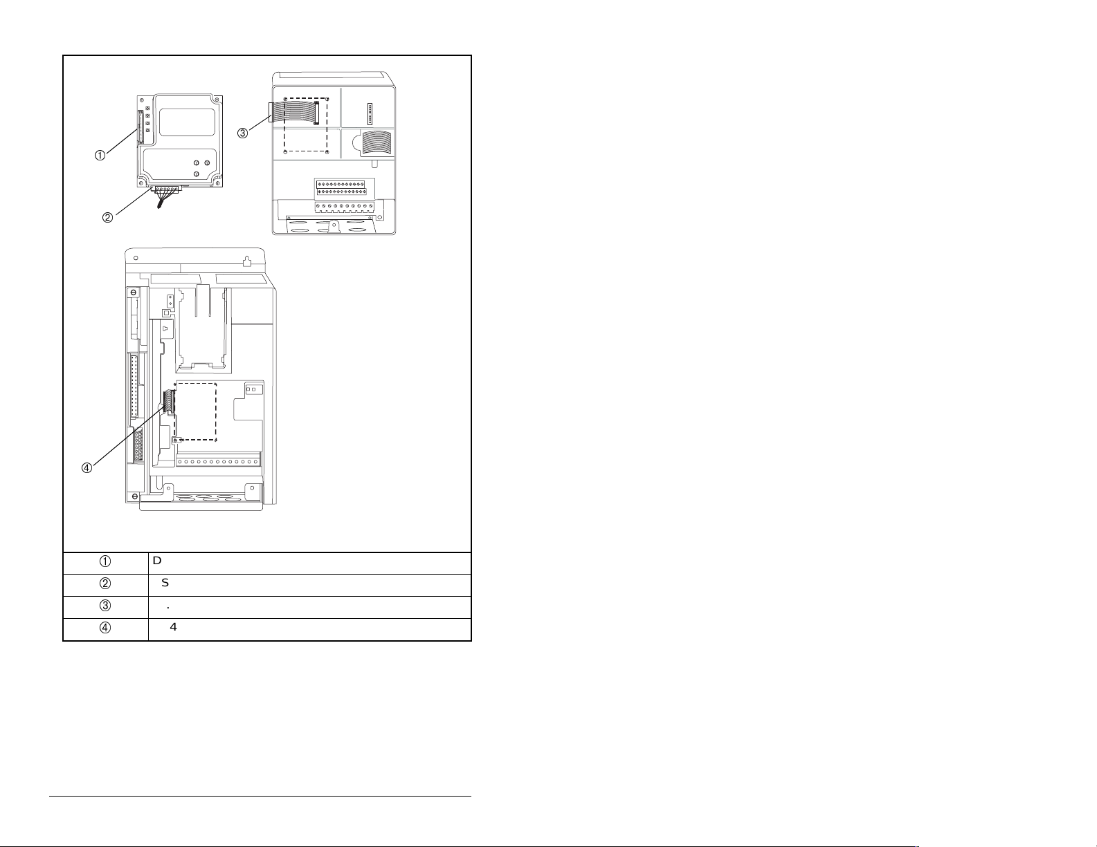
RS485 DF1 Module
SP600 Drive
Frame 2 and Larger
SP600 Drive
1-20 HP
3-4
DPI Connector
RS485 Connector
15.24 cm (6 in) Internal Interface cable
2.54 cm (1 in) Internal Interface cable
Figure 3.3 – DPI Ports and Internal Interface Cables
RS485 DF1 Communications Module
Page 19
SP600 Drive
1-20 HP
Drive
Module
Internal Interface cable
folded behind the module
and in front of the drive
Figure 3.4 – Mounting the Module
Installing the RS485 DF1 Module
SP600 Drive
Frame 2 and Larger
3-5
Page 20
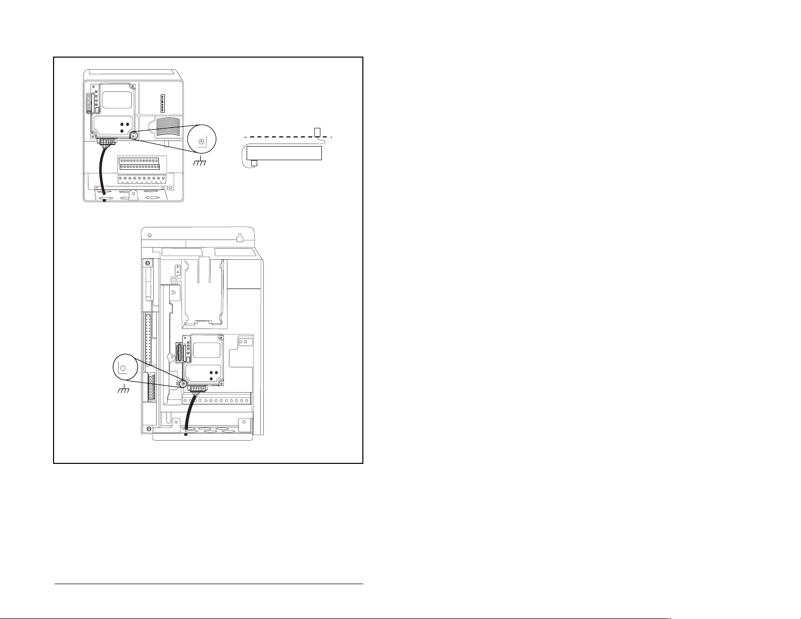
3.4 Connecting the Module to the
Network
ATTENTION:The SP600 drive may contain high
voltages that can cause injury or death. Remove
!
Step 1. Remove power from the drive.
Step 2. Use static control precautions.
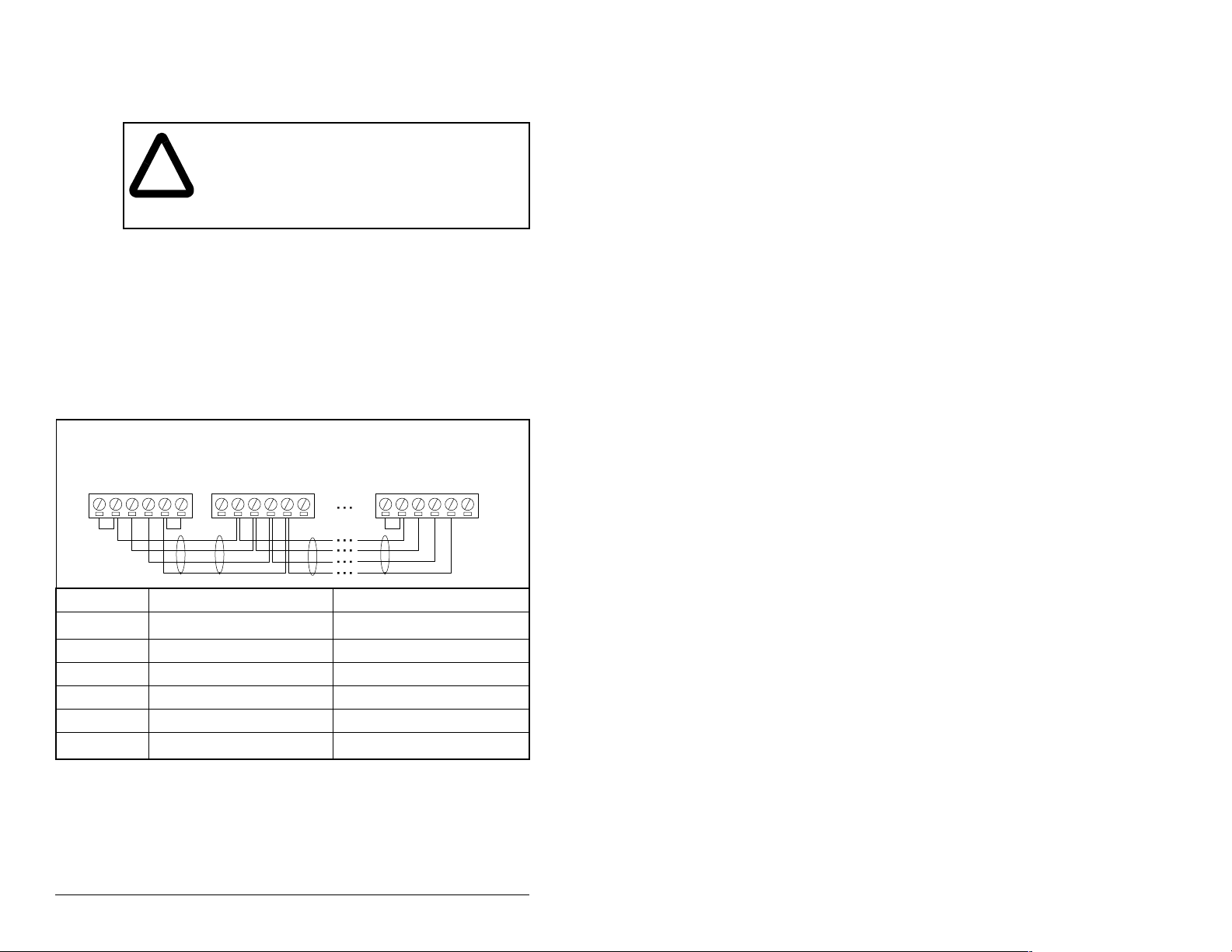
Step 3. Connect an RS485 cable to the network, and route it
Step 4. Connect a 6-pin linear plug to the RS485 cable.
Step 5. Connect the cable to the module.
See figure 3.5 for typical network connections.
Node 1 Node 2 Node "n"
power from the drive, and then verify power has
been discharged before installing or removing a
module. Failure to observe this precaution could
result in severe bodily injury or loss of life.
through the bottom of the drive.
TERMAB
COM
SHIELD
GND
TERMAB
COM
SHIELD
GND
TERMAB
COM
SHIELD
GND
Terminal Signal Function
GND
Chassis Ground
1
Shield GND termination
SHIELD Shield Shield RC termination
COM Common Signal Common
B Signal B Tx Rx DA Signal A Tx Rx D+
TERM
1
The shield must be grounded at a single point on the network (jumper terminals
SHIELD and GND).
2
Jumper terminals TERM and A on the modules at the end of the RS485 network.
This enables a built-in RC termination network on the module.
Termination
Figure 3.5 – Typical Network Connections
2
3-6
Signal RC termination
RS485 DF1 Communications Module
Page 21

3.5 Applying Power
ATTENTION:Unpredictable operation m ay oc cu r
if parameter settings and switch settings are not
!
compatible with your application. Verify that
settings are compatible with your application
before applying power to the drive. Failure to
observe these precautions could result in severe
bodily injury of loss of life.
Step 1. Close the door or reinstall the cover on the drive. The
Step 2. Ensure th at the m odule will hav e a uni que ad dress on the
Step 3. Apply power to the drive. The module receives its power
Step 4. If the Data Rate switch is set to “PGM,” use a
Step 5. Verify that the master and network are installed and
status indicators can be viewed on the front of the drive
after power has been applied.
network and is set at the correct data rate. If a new data
rate or address is needed, reset the switches (refer to
Commissioning the Modul e, sec tion 3.2).
from the connected drive. When you apply power to the
product for the first time, the status indicators should be
green after an initialization. If there is a problem, refer to
chapter 6.
configuration tool to set the data rate and node address
parameters in the module (refer to chapter 4, Configuring
the RS485 DF1 Module).
functioning in accordance with RS485 DF1 standards.
Installing the RS485 DF1 Module
3-7
Page 22

3-8
RS485 DF1 Communications Module
Page 23

CHAPTER 4
Configuring the
RS485 DF1 Module
Chapter 4 provides instructions and information for setting the
parameters in the module.
For a complete list of parameters, refer to Appendix B, RS485 DF1
Module Parameters. For defini tio ns of term s in this chap ter, refer to
the Glossary.
4.1 Configuration Tools
The module sto res p a r am ete rs and other information in its own no nvolatile memory. Therefore, you must access the module to view
and edit its parameters. Table 4.1 lists the tools that can be used to
access the mo dule parameters.
Table 4.1 – Configuration Tools
Tool R efer to:
VS Utilities Software VS Utilities online help
LCD OIM Section 4.2
Configuring the RS485 DF1 Module
4-1
Page 24

4.2 Using the LCD OIM to Configure the
Module
Use the procedure in figure 4.1 to access the parameters on the
RS485 DF1 module using the LCD OIM. If you are unfamiliar with
the operation of the LCD OIM, refer to the SP600 AC Drive User
Manual (D2-3485 or D2-3501) for more information.
>>
Stopped
P0: SP600
Main Menu
Device Select
Monitor
Use to highlight
Device Select icon
Auto
Lang
>>
Stopped
P0: SP600
Device: Port 0
SP600
RECOMM-485
Use to select
RECOMM-485.
Auto
Figure 4.1 – Accessing the Module Parameters using the LCD OIM
4.3 Setting the Node Address
If the Data Rate switch on the module is set to “PGM,” the value of
module parameter 3 (DF1 Addr Cfg) determines the node address.
Step 1. Set the value of module parameter 3 (DF1 Addr Cfg) to a
unique node address.
Port 5 Device
RECOMM-485
Parameter #: 3
DF1 Addr Cfg
1
0 <> 99
Default = 1
>>
Stopped
P5: RECOMM-485
Main Menu
Parameters
Edit the RS485 DF1
parameters using the
same techniques as for
drive parame ters.
Auto
4-2
Figure 4.2 – RS485 DF1 Node Address Screen on an LCD OIM
Step 2. Reset the module. Refer to section 4.7.2, Resetting the
Module.
RS485 DF1 Communications Module
Page 25

4.4 Setting the Data Rate
If the Data Rate switch on the module is set to “PGM,” the value of
module parameter 5 (DF1 Rate Cfg) determines the RS485 DF1
data rate. Your application may require a different setting.
Step 1. Set the value of module parameter 5 (DF1 Rate Cfg) to
the data rate at which your network is operating. Refer to
figure 4.3.
Port 5 Device
RECOMM-485
Parameter #: 5
DF1 Rate Cfg
3
9600 bps
Figure 4.3 – Data Rate Screen on an LCD OIM
Value Baud Rate
0 1200 bps
1 2400 bps
2 4800 bps
3 9600 bps (default)
4 19.2 kbps
5 38.4 kbps
Step 2. Reset the module. Refer to section 4.7.2, Resetting the
Module.
4.5 Setting the Error- Checking Method
Two types of error-checking methods are used with the DF1
protocol: Cyclic Redundancy Check (CRC) and Block Check
Character (BCC). (Refer to the Glossary for a description of each
method.)
Step 1. Set the value of module parameter 24 (CRC/BCC) to the
method used by the network as shown in figure 4.4.
Port 5 Device
RECOMM-485
Parameter #: 24
CRC/CBC
0
BCC
Value Selection
0 BCC (default)
1CRC
Figure 4.4 – Error-Checking Method Screen on an LCD OIM
Step 2. Reset the module. Refer to section 4.7.2, Resetting the
Module.
Configuring the RS485 DF1 Module
4-3
Page 26

4.6 Setting the I/O Configuration
The I/O configuration determines the type of data sent to the drive.
This is a two-part process: enabling/disabling the data transmitted
between the module and the drive, and identifying the data
transmitted between the module and the master (i.e., scanner).
Step 1. Enable or disable the data transmitted between the
module and the drive by setting the bits in module
parameter 12 (DPI I/O Config).
A “1” enables the I/O. A “0” disables the I/O. Bit 0 is the
right-most bit. In figure 4.5, it is highlighted and equals
“1.”
Port 5 Device
RECOMM-485
Parameter #: 12
DPI I/O Config
xxxxxxxxxxx0000
Cmd/Ref b00
Figure 4.5 – I/O Configuration Screen on an LCD OIM
Bit Description
0 Logic Command/Reference (Default)
1Datalink A
2Datalink B
3Datalink C
1
4Datalink D
5 - 15 Not Used
Step 2. If Logic Command/Reference is enabled (default),
configure the parameters in the drive to accept the Logic
Command and Reference from the module. For example,
set Speed Ref A Sel (SP600 drive parameter 90) to
“Network” so that the drive uses the Reference from the
module. Also, verify that SP600 drive para meter 89 (Logic
Source Sel) is configured to recei ve the desired logic from
the module.
Step 3. If you enabled one or mor e Datali nks (option al), configu re
parameters in the drive to determine the source and
destination of dat a in the Data link(s). Also, e nsure that the
RS485 DF1 module is the only module us in g the enabled
Datalink(s).
Step 4. Reset the module. Refer to section 4.7.2, Resetting the
Module.
The module is ready to receive I/O from the master (i.e., scanner).
You must now configure the scanner to recognize and transmit I/O
to the module.
4-4
RS485 DF1 Communications Module
Page 27

4.7 Setting a Fault Action
By default, when communications are disrupted (for example, a
cable is disconnected) or the scanner is idle, the drive responds by
faulting if it is using I/O from the network.
You can configure a different response to communication
disruptions using module parameter 10 (Comm Flt Action).
ATTENTION:Module parameter 10 (Comm Flt
Action) lets you det erm ine the ac ti on of the module
!
Set the value of module parameter 10 (Comm Flt Action) to the
desired response a s shown in t able 4.2 . See figure 4 .6 for a sa mple
LCD OIM Fault Action screen.
Table 4.2 – Selections for Drive Response to Communication Fault
Value Action Description
0 Fault (default) The drive is faulted and stopped
1 Stop The drive is stopped, but not
2 Zero Data The drive is sent 0 for output data
3 Hold Last The drive continues in its present
4 Send Flt Cfg The drive is sent the data that you
and connected drive if communications are
disrupted. By defau lt, this parameter faul ts the drive.
Y ou can set the parameter so that the driv e continues
to run. Precautions should be taken to ensure that
the setting of this parameter does not create a risk
of injury or equipment damage.
(Default).
faulted.
after a communi cations disru ption.
This does not command a stop.
state.
set in the fault configuration
parameters 14 through 23 (Flt Cfg
Logic through Flt Cfg D2 In).
Figure 4.6 – Fault Action Screen on an LCD OIM
Changes to this parameter take effect immediately. A reset is not
required.
Configuring the RS485 DF1 Module
Port 5 Device
RECOMM-485
Parameter #: 10
Comm Flt Action
0
Fault
4-5
Page 28

4.7.1 Setting the Fault Configuration Parameters
If you set module param eter 10 (Comm Flt Ac tion) to “Send Fl t Cfg,”
the values in the par ameters show n in table 4.3 are sent to t he drive
after a communications fault occurs. Yo u must set these parameters
to values required by your application.
Table 4.3 – Fault Configuration Parameters
Parameter
Number Name Description
14 Flt Cfg Logic A 16-bit value sent to the drive
for Logic Command.
15 Flt Cfg Ref A 32-bit value (0 to 429 4967295)
16 - 23 Flt Cfg x1 In
Flt Cfg x2 In
Changes to these par ameters t ake ef fect immedia tely. A reset is not
required.
sent to the drive as a Reference
or Datalink.
Important: If the drive uses a
16-bit Reference or 16-bit
Datalinks, the most significant
word of the value must be set to
zero (0) or a fault will occur.
4.7.2 Resetting the Module
4-6
Changes to swit ch settin gs or some modul e paramet ers req uire that
you reset the module before the new settings take effect. You can
reset the module by cycling power to the drive or by using module
parameter 9 (Reset Module).
ATTENTION: If the module is transmitting control
I/O to the drive, the drive may fault when you reset
!
the module. Determi ne h ow yo ur dri ve w ill respond
before resetting a connected module. Failure to
observe this precaution could result in bodily injury
or damage to equipment.
RS485 DF1 Communications Module
Page 29

Set module parameter 9 (Reset Module) to “Reset Module.” See
figure 4.7.
Port 5 Device
RECOMM-485
Parameter #: 9
Reset Module
1
Reset Module
Figure 4.7 – Reset Screen on an LCD OIM
Value Description
0 Ready (default)
1 Reset Module
2 Set Defaults
When you enter 1 (“Reset Module”) the module is immediately
reset. When you enter 2 (“Set Defaults”) the module sets all
module parameters to their factory-default settings. The module
should be reset after performing a “Set Defaults.”
The value of this parameter is restored to 0 (“Ready”) after the
module is reset.
Configuring the RS485 DF1 Module
4-7
Page 30

4.8 Viewing the Module Configuration
The parameters in table 4.4 provide information about how the
module is configured. You can view these parameters at any time.
Table 4.4 – Module Configuration Status Parameters
No. Name Description
01 DPI Port The port to which the module is connected. This will usually be
02 DPI Data Rate The data rate used by the drive. This data rate is set in the
04 DF1 Addr Actual The node address actually used by the module. This will be
06 DF1 Rate Actual The DF1 data rate actually used by the module. This will be
07 Ref/Fdbk Size The size of the Reference/Feedback (16 bits or 32 bits). It is
08 Datalink Size The size of the Datalinks (16 bits or 32 bits). It is set in the
11 Active Cfg The source from which the module address and data rate are
13 DPI I/O Active The I/O used by the module. The value of this parameter will
25 CRC/BCC Act The actual error-checking method selected.
26 Dup Msg Detect Determines if the module ignores messages with duplicate
port 5.
drive and the module detects it.
one of the following values:
• The address set by the Node Address switches on the
module.
• The value of module parameter 3 (DF1 Addr Cfg) if the
switches have been disabled.
one of the following values:
• The data rate set by the Data Rate switch on the module.
• The value of module parameter 5 (DF1 Rate Cfg) if the
switches have been disabled.
set in the drive and the module automatically uses the correct
size.
drive and the module automatically uses the correct size.
taken. This will either be switches on the module or
parameters in EEPROM. It is determined by the switch
settings on the module.
be equal to the value of module parameter 12 (DPI I/O Config)
unless the parameter was changed and the module was not
reset.
Bit Definitions
Bit
Default
TNS IDs. Normally set to Enable (default). Set to Disable if
using a ProSoft 3150-DFM module or any device that does not
increment the TNS ID.
01234576
10000xxx
0 = Cmd/Ref
1 = Datalink A
2 = Datalink B
3 = Datalink C
4 = Datalink D
5 = Not Used
6 = Not Used
7 = Not Used
4-8
RS485 DF1 Communications Module
Page 31

CHAPTER 5
Using VS Utilities
on the RS485 Network
Chapter 5 provides instructions for configuring VS Utilities (version
1.01 or higher) to access SP600 drives on the RS485 network.
Figure 5.1 shows a typical RS485 DF1 network.
VS Utilities
To connect to the network using VS Utilities:
Step 1. Select Ex
5.2.
VS Utilities
Using VS Utilities on the RS485 Network
RECOMM-232
Serial Converter
Module
Figure 5.1 – Typical RS485 DF1 Network
plore > Connect > Network as shown in figure
Figure 5.2 – Connecting to the Network
SP600 DrivesPC Running
5-1
Page 32

Step 2. Select Single to connect to a singl e node on th e netwo rk.
Select Multiple to connect to multiple nodes and enter
the node range (figure 5.3).
“Offline” or “Online” text will be displayed next to the
number to show if the particular node is present on the
network. In this example, two nodes with DF1 addresses
of 1 and 2 will be accessed.
Figure 5.3 – Node Selection Screen: Multiple Nodes Selected
Step 3. Click Connect.
VS Utilities will perform a search within the range of the
selected nodes and list them as shown in figure 5.4.
VS Utilities
5-2
Figure 5.4 – Results of Search of Selected Nodes
RS485 DF1 Communications Module
Page 33

Step 4. Click on each node to have VS Utilities perform a device
read as shown in figure 5.5. A “+” w i ll a ppe ar to th e le f t of
the node upon completion.
VS Utilities
Node 1: - SP600
Node 2: - SP600
Figure 5.5 – Result of Device Read Performed by VS Utilities
Step 5. Click on the “+” for each node to expand the information
as shown in figure 5.6.
VS Utilities
Node 1: - SP600
0 - SP600 240V 4.2A
1 - LCD OIM
2 - RECOMM-232 RS232 DF1
5 - RECOMM-485 RS485 DF1
Node 2: - SP600
Node 2: - SP600
0 - SP600 240V 4.2A
1 - LCD OIM
5 - RECOMM-485 RS485 DF1
Figure 5.6 – Expanding Each Node
Using VS Utilities on the RS485 Network
5-3
Page 34

Step 6. Click on the desired item to access its parameters as
shown in figure 5.7.
VS Utilities
Node 1: - SP600
0 - SP600 240V 4.2A
1 - LCD OIM
2 - RECOMM-232 RS232 DF1
5 - RECOMM-485 RS485 DF1
Node 2: - SP600
0 - SP600 240V 4.2A
1 - LCD OIM
5 - RECOMM-485 RS485 DF1
Figure 5.7 – Accessing the Parameters in the Selected Device
5-4
RS485 DF1 Communications Module
Page 35

CHAPTER 6
Troubleshooting the
Module and Network
Chapter 6 contains information for troubleshooting the RS485 DF1
module and the network.
6.1 Understanding the Status Indicators
The module has four status indicators. They can be viewed on the
module or through the drive cover. (See figure 6.1.)
➀
➁
➂
➀
➁
➂
➃
➃
Status
Number
➀
➁
➂
➃
Indicator Description Refer to...
DRIVE DPI Connection Status Section 6.1.1
MS Module St a t us Section 6.1.2
NET A DF1 Status Section 6.1.3
NET B DF1 Traffic Section 6.1.4
Figure 6.1 – Status Indicators (Location on Drive May Vary)
Troubleshooting the Module and Network
6-1
Page 36

6.1.1 DRIVE Status Indicator
Table 6.1 – DRIVE Status Indicator: State Definitions
Status Cause Corrective Action
Off The module is not
Flashing
Red
Solid
Red
Orange The module is
Flashing
Green
Solid
Green
powered or is not
connected properly to
the drive.
The module is not
receiving a ping
message from the
drive.
The drive has refused
an I/O connection from
the module.
Another DPI peripheral
is using the same DPI
port as the module.
connected to a product
that does not support
Reliance Electric DPI
communications.
The module is
establishing an I/O
connection to the drive
or module parameter
12 (DPI I/O Config) is
configured for all I/O
disabled.
The module is properly
connected and is
communicating with the
drive.
• Securely connect the
module to the dri ve using the
Internal Interface cable.
• Apply power to the drive.
• Verify that cables are
securely connected.
• Cycle power to the drive.
Important: Cycle power to the
product after m aking any of the
following corrections:
• Verify that all DPI cables are
securely connected and not
damaged. Replace cables if
necessary.
• Verify that the DPI Host
supports Datalinks.
• Configure the module to u se
a Datalink that is not already
being used by another
peripheral.
• Connect the module to a
product that supports
Reliance Electric DPI
communications (for
example, SP600 drives).
• Verify the se ttin gs in modu le
parameter 12 (DPI I/O
Config).
• Normal behavior if no DPI
I/O is enabled. No action is
required.
• No action is required.
6-2
RS485 DF1 Communications Module
Page 37

6.1.2 MS Status Indicator
Table 6.2 – MS Status Indicator: State Definitions
Status Cause Corrective Action
Off The module is not
Flashing
Red
Solid
Red
Flashing
Green
Solid
Green
powered.
The module has
failed the firmware
test.
The module has
failed the hardware
test.
The module is
operational but is not
transferring I/O data.
The module is
operational and
transferring I/O data.
• Securely connect the module
to the SP600 drive using the
Internal Interface cable.
• Apply power to the drive.
• Clear faults in the module.
• Cycle power to the drive.
• If cycling power does not
correct the problem, the
parameter settings may have
been corrupted. Reset defau lts
and reconfigure the module.
• If resetting defaults does not
correct the problem, flash the
module with the latest fi rmware
release.
• Cycle power to the drive.
• Replace the module.
• Place the scanner in RUN
mode.
• Program the controller to
recognize and transmit I/O to
the module.
• Configure the module for the
program in the controller.
• Normal behavior if no DPI I/O
is enabled.
• No action required.
Troubleshooting the Module and Network
6-3
Page 38

6.1.3 NET A Status Indicator
Table 6.3 – NET A Status Indicator: State Definitions
Status Cause Corrective Actions
Off The module is not
Flashing
Green
Solid
Green
Flashing
Red
powered or the
module is not
properly
connected to the
network.
The module is
properly
connected, but it is
not communicating
with any devices
on the network.
The module is
properly
connected and
communicating on
the network.
A network
connection has
timed out.
• Securely connect th e module to
the drive using the Internal
Interface cable.
• Correctly connect the RS485
cable to the DF1 plug.
• Apply power to the drive.
• Place the controller in RUN, or
apply power to the peer device
that will send I/O.
• Program a controller or peer
device to recognize and
transmit I/O to the module.
• Configure the module for the
program in the controller or the
I/O from the peer source.
• No action required.
• Place the scanner in RUN, or
apply power to the peer device
that will send I/O.
• Check the amount of traffic on
the network.
6-4
RS485 DF1 Communications Module
Page 39

6.1.4 NET B Status Indicator
Table 6.4 – NET B Status Indicator: State Definitions
Status Cause Corrective Actions
Off The module is not
receiving data over
the network.
• Place the controller in RUN, or
apply power to the peer device
that will send I/O.
• Program a controller peer
device to recognize and
transmit I/O to the module.
• Configure the module for the
program in the controller or the
I/O from the peer device.
Flashing
Green
The module is
receiving data over
the network.
• No action required.
6.2 Module Diagnostic Items
Table 6.5 lists diagnostic items that can be accessed using
VS Utilities software or the LCD OIM.
Table 6.5 – Module Diagnostic Items
No. Event Description
1 Common Logic
Cmd
2 Prod Logic Cmd The current value of the Product Specific Logic
3 Reference The current value of the Product Specific
4 Common Logic Sts The current value of the Common Logic Status
5 Product Logic
Status
6 Feedback The current value of the Product Specific
The current value of the C ommon Logic
Command being transmitted to the host by this
peripheral.
Command being transmitted to the host by this
peripheral.
Reference being transmitted to the host by the
peripheral.
being received from the host by this peripheral.
The current value of the Product Specific Status
being received from the host by this peripheral.
Feedback being received from the host by this
peripheral.
Troubleshooting the Module and Network
6-5
Page 40

Table 6.5 – Module Diagnostic Items (Continued)
No. Event Description
7
Datalink A1 In
8
Datalink A2 In
9
Datalink B1 In
10
Datalink B2 In
11
Datalink C1 In
12
Datalink C2 In
13
Datalink D1 In
14
Datalink D2 In
15
Datalink A1 Out
16
Datalink A2 Out
17
Datalink B1 Out
18
Datalink B2 Out
19
Datalink C1 Out
20
Datalink C2 Out
21
Datalink D1 Out
22
Datalink D2 Out
The current value of the specified Datalink In
being transmitted to th e host by th e module. If the
module has not ena bled th e Dat ali nk, th e valu e is
0.
The current value of the specified Datalink Out
being received from the host by the module.
23 Field Flash Cnt The current value of the Field Flash Counter (that
is, the number of time s this dev ice has been flash
updated).
24 DPI Rx Errors The current value of the DPI CAN Receive Error
Counter register.
25 DPI Tx Errors The current value of the DPI CAN Transmit Error
Counter register.
26 Clear DF1 Counts Ready = No action.
Enable = Clears all DF1 counter parameters.
27 DF1 Packets Sent The number of DF1 packets sent by the
peripheral.
28 DF1 Packets Rcvd The number of DF1 packets received by the
peripheral.
29 Undelivered Msgs Reports the number of DF1 packets that were
sent by the peripheral, but not acknowledged.
30 ENQs Received Reports the number of ENQ requests recei ved by
the peripheral.
31 NAK Bak Packet The number of responses receiv ed (BCC o r CRC
calculated by peripheral did not match that in the
packet).
32 NAK No Memory The number of requests received by the
peripheral that could not processed due to
insufficient memory available to buffer the
incoming packet.
33 Duplicate Msgs The number of duplicate messages received by
the peripheral. A duplicate message is detected
when the SRC, TNS, and CMD files of two
consecutive messages are identical.
6-6
RS485 DF1 Communications Module
Page 41

Table 6.5 – Module Diagnostic Items (Continued)
No. Event Description
34 PCCC I/O Timeout The I/O communication timeout value (secs)
before the action selected in module parameter
10 (Comm Flt Action) is taken.
35 Data Rate SW The value of the Data Rate switch on the module.
36 Node Address SW The value of the Node Address swi tch on the
module.
6.3 Viewing and Clearing Eve nts
The module maintains an event queue that reports the history of its
actions. You can view the event queue using an LCD OIM or
VS Utilities software.
To View and Clear Events Using an LCD OIM
Use the procedure shown in figure 6.2 to access the event queue
using the LCD OIM. Note that you must have the RECOMM-485
module as the selected device to access the event queue.
>>
Stopped Auto
P0: RECOMM-485
Main Menu
Diagnostics
Monitor
Highlight Diagnostics icon
Lang
Diagnostics:
View Event Queu e
Device Version
OIM Version
Highlight item
1
EvtQ# : E#xxxxx
Online @ 500kbps
Clrqu
Press F2 key to
clear event queue
Figure 6.2 – Viewing and Clearing Events Using an LCD OIM
Troubleshooting the Module and Network
6-7
Page 42

Events
Many events in the event queue occur under normal operation. If
you encounter unexpected communications problems, the events
may help you or Reliance Electric personnel troubleshoot the
problem. Table 6.6 lists events that may appear in the event queue.
Table 6.6 – Event Codes and Descriptions
Code Event Description
1 No Event Empty event queue entry.
2 DPI Bus Off Flt A bus-off condition was detected on DPI. This
3 Ping Time Flt A ping message was not received on DPI
4 Port ID Flt The mod ule is not conn ected t o a correct po rt
5 Port Change Flt The DPI port changed.
6 Host Sent Reset The DPI product issued this because it was
7 EEPROM Sum Flt The EEPROM in the module is corrupt.
8 Online @ 125 kbps The module and DPI product are
9 Online @ 500 kbps The module and DPI product are
10 Bad Host Flt The module was connected to an
1 1 Dup. Port Flt Another peripheral with the same port number
12 Type 0 Login The module has logged in for type 0 control.
13 Type 0 Time Flt The module has not received a type 0 status
14 DL Login The module has logged into a Datalink.
15 DL Reject Flt The host rejected an attempt to log in to a
16 DL Time Flt The module has not received a Datalink
17 Control Disabled The module has se nt a “Soft Control Disable”
18 Control Enabled The module has sent a “Soft Control Enable”
19 PCCC IO Time Flt The module has not received a PCCC control
event may be caused by loose or broken
cables or by noise.
within the specified time.
on a DPI product.
reset.
communicating at 125 kbps.
communicating at 500 kbps.
incompatible product.
is already in use.
message within the specified time.
Datalink because the Datalink is not
supported or is used by another peripheral.
message within the specified time.
command to the DPI product.
command to the DPI product.
message within the specified timeout interval.
6-8
RS485 DF1 Communications Module
Page 43

Table 6.6 – Event Codes and Descriptions (Continued)
Code Event Description
20 Normal Startup The module successfully started up.
21 Message Timeout A Client-Server message sent by the
peripheral was not completed.
22 DPI Fault Msg The DPI host has faulted.
23 DPI Fault Clear The DPI host transitioned from a faulted to a
non-faulted state.
24 Flt Cfg Error At least one of the Fault Configuration
parameters contains a value greater than
65535 and th e DPI product expects a 16-bit
value.
25 DF1 NAK NAK received.
26 Manual Reset The module was reset by the user.
27 Language CRC Bad The language text memory segment is
corrupt.
Troubleshooting the Module and Network
6-9
Page 44

6-10
RS485 DF1 Communications Module
Page 45

APPENDIX A
Technical
Specifications
Communications
Network
Protocol
Data Rates
Drive
Protocol
Data Rates
Electrical
Consumption
Drive 150 mA at 5 VDC supplied through the drive
Mechanical
Dimensions
Height
Length
Width
Weight 60 g (2 oz)
DF1
1200, 2400, 4800, 9600, 19.2 K, 38.4 K, PGM
If the Data Rate switch is set to “PGM,” the
module will use the setting of module
parameter 5 (DF1 Rate Cfg) for the data rate.
DPI
125 K or 500 K
16 mm (0.625 in)
86 mm (3.34 in)
81 mm (3.16 in)
Environmental
Temperature
Operating
Storage
Relative Humidity 5 to 95% non-condensing
Atmosphere Important: The module must not be
Technical Specifications
-10 to +50°C (14 to 149°F)
-40 to +85°C (-40 to 185°F)
installed in an area where the ambient
atmosphere contains volatile or corrosive
gas, vapor, or dust. If the module is not
going to be installed for a period of time, it
must be stored in an area where it will not
be exposed to a corrosive atmosphere.
A-1
Page 46

Regulatory Compliance
UL 508C and CUL
CE EN61800-3
A-2
RS485 DF1 Communications Module
Page 47

APPENDIX B
RS485 DF1 Module
Parameters
The following information is provided for each module parameter
along with its description:
Parameter Number: Unique number assigned to each
Parameter Name: Unique name assigned to each
Range: Predefined parameter limits or
Default: Factory default setting.
Type: Read Only or Read/Write.
Reset Required: Module must be reset before p arame ter
About Parameter Numbers
The parameters in the RS485 DF1 module are numbered
sequentially. However, depending on the configuration tool used,
they may have different numbers.
Configuration Tool Numbering Schemes
• VS Utilities
•OIM
parameter.
parameter.
selections.
value is recognized.
The module parameters begin with
parameter 1. For example, parameter 01
(DPI Port) is parameter 1 as indicated by
the manual.
RS485 DF1 Module Parameters
B-1
Page 48

1 DPI Port
Range: 0 to 7
Default: 5
Type: Read Only
Reset Required: N/A
Displays the port to w hich the m odule is co nnected. This will usually
be port 5.
2 DPI Data Rate
Range: 0 = 125 Kbps
Default: 0 = 125 Kbps
Type: Read Only
Reset Required: N/A
Displays the dat a rate us ed by the driv e. This rate is set in t he d riv e
and the module detects it.
1 = 500 Kbps
3 DF1 Addr Cfg
Range: 0 to 254
Default: 1
Type: Read/Write
Reset Required: Yes
Sets the node address if the Dat a Rate Sw itc h on the module is se t
to “PGM” (Program).
4 DF1 Addr Actual
Range: 0 to 254
Default: 1
Type: Read Only
Reset Required: N/A
Displays the DF1 node address actually used by the module.
B-2
RS485 DF1 Communications Module
Page 49

5 DF1 Rate Cfg
Range: 0 = 1200 bps
Default: 3 = 9600 bps
Type: Read/Write
Reset Required: Yes
Sets the DF1 data rate if the Data Rate switch on the module is set
to “PGM” (Program).
1 = 2400 bps
2 = 4800 bps
3 = 9600 bps
4 = 19.2 kbps
5 = 38.4 kbps
6 DF1 Rate Actual
Range: 0 = 1200 bps
Default: 3 = 9600 bps
Type: Read Only
Reset Required: Yes
Displays the DF1 data rate actually used by the module.
1 = 2400 bps
2 = 4800 bps
3 = 9600 bps
4 = 19.2 kbps
5 = 38.4 kbps
7 Ref/Fdbk Size
Range: 0 = 16-bit
1 = 32-bit
Default: 0 = 16-bit
Type: Read Only
Reset Required: N/A
Displays the size of the Refer enc e/Feed back. The driv e determ ines
the size of the Reference/Feedback.
8 Datalink Size
Range: 0 = 16-bit
1 = 32-bit
Default: 0 = 16-bit
Type: Read Only
Reset Required: N/A
Displays the size of each Datalink word. The drive determines the
size of Datalinks.
RS485 DF1 Module Parameters
B-3
Page 50

9 Reset Module
Range: 0 = Ready (No action)
Default: 0 = Ready
Type: Read/Write
Reset Required: No
This parameter is a command. It resets the module if set to “Reset
Module.” It restores the module to factory default settings if set to
“Set Defaults.” No action is taken if set to “Ready.” The parameter
resets to “0 = Ready” after the command is performed.
1 = Reset Module
2 = Set Defaults (Restores module to factory-default
settings)
ATTENTION: If the module is transmitting I/O that
controls the drive, the drive may faul t when you reset
!
the module. Determ ine h ow you r d riv e w ill re sp ond
before resetting a connected module. Failure to
observe this precaution cou ld resul t in bod il y inj ury
or damage to equipment.
10 Comm Flt Action
Range: 0 = Fault
Default: 0 = Fault
Type: Read/Write
Reset Required: No
1 = Stop
2 = Zero Data
3 = Hold Last
4 = Send Flt Cfg
B-4
Sets the action that the module ta kes when the modul e d etec t s th at
RS485 DF1 communications have been disrupted. This setting is
effective only if I/O that controls the drive is transmitted though the
module.
ATTENTION: Comm Flt Action (module paramete r
10) lets you determine the action of the module and
!
connected drive if commun ications are disrupted. By
default, this par am ete r fa ults the drive. You can set
this parameter so that the drive continues to run.
Take precautions to ensure that the setting of this
parameter does not create a hazard of injury or
equipment damage. Failure to observe this
precaution could resu lt in bodily injury or dama ge to
equipment.
RS485 DF1 Communications Module
Page 51

11 Active Cfg
Range: 0 = Switches
Default: 0 = Switches
Type: Read Only
Reset Required: N/A
Displays the source from which the module node address and data
rate are taken. This will either be switches on the module or
parameters in EEPROM. The source is determined by the settings
of the switches on the module. See chapter 3, Installing the RS485
DF1 Module, for more information about the switches.
1 = EEPROM
12 DPI I/O Cfg
Range: See figure B.1 .
Default: xxx0 0001
Type: Read/Write
Reset Required: Yes
Configures the I/O that is transferred through the module. See
figure B.1
Figure B.1 – DPI I/O Config (Parameter 12)
RS485 DF1 Module Parameters
Not Used
Not Used
Not Used
Datalink C
Datalink D
Datalink B
00010xxx
Datalink A
Cmd/Ref
01234567
1= I/O Enabled
0= I/O Disabled
x=Not Used
B-5
Page 52

13 DPI I/O Active
Range: See figure B.2.
Default: xxx0 0001
Type: Read Only
Reset Required: N/A
Displays the I/O that the module is actively transmitting. The value
of this parameter will usually be equal to the value of module
parameter 12 (DPI I/O Cfg). See figure B.2.
1= I/O Enabled
Cmd/Ref
01234567
0= I/O Disabled
x=Not Used
Datalink C
Datalink D
Not Used
Not Used
Not Used
Figure B.2 – DPI I/O Active (Parameter 13)
Datalink A
Datalink B
00010xxx
14 Flt Cfg Logic
Range: 0000 0000 0000 0000 to 1111 1111 1111 1111
Default: 0000 0000 0000 0000
Type: Read/Write
Reset Required: No
Sets the Logic Command data that is sent to the drive if module
parameter 10 (Comm Flt Action) is set to “Send Flt Cfg” and
communications are disrupted.
The bit definitio ns will d epend on the produc t to wh ich the mod ule is
connected.
15 Flt Cfg Ref
Range: 0 to 4294967295
Default: 0
Type: Read/Write
Reset Required: No
Sets the Reference data that is sent to the drive if module
parameter 10 (Comm Flt Action) is set to “Send Flt Cfg” and
communications are disrupted.
Important: If the drive uses a 16-bit Ref erence , the most signi fican t
B-6
word of this value must be set to zero (0) or a fault will
occur.
RS485 DF1 Communications Module
Page 53

Flt Cfg A1
16
Flt Cfg A2
17
Flt Cfg B1
18
Flt Cfg B2
19
Flt Cfg C1
20
Flt Cfg C2
21
Flt Cfg D1
22
Flt Cfg D2
23
Range: 0 to 4294967295
Default: 0
Type: Read/Write
Reset Required: No
Sets the data that is sent to the Datalink in the drive if module
parameter 10 (Comm Flt Action) is set to “Send Flt Cfg” and
communications are disrupted.
Important: If the drive uses a 16-bit Ref erence , the most signi fican t
word of this value must be set to zero (0) or a fault will
occur.
24 CRC/BCC Cfg
Range: 0 = BCC (Block Check Character)
Default: 0 = BCC
Type: Read/Write
Reset Required: Yes
1 = CRC (Cyclic Redundancy Check)
Selects the method of error detection for data communications. This
setting must match the method used by the software or controller
communicati ng with the mod ule.
25 CRC/BCC Act
Range: 0 = BCC (Block Check Character)
1 = CRC (Cyclic Redundancy Check)
Default: 0 = BCC
Type: Read Only
Reset Required: N/A
Displays the actual method of error detection used.
RS485 DF1 Module Parameters
B-7
Page 54

26 Dup Msg Detect
Range: 0 = Disable
Default: 1 = Enable
Type: Read/Write
Reset Required: No
Enables/disables duplicate message detection by the module.
Normally, this is set to “Enable” (default). Set to “Disable” if using a
ProSoft 3150-DFM module or any device that does not increment
the TNS (transaction number) ID.
1 = Enable
B-8
RS485 DF1 Communications Module
Page 55

Logic Command/
Appendix C provides the definitions of the Logic Command/Logic
Status words that are used for some products that can be
connected to the RS485 DF1 module. If you do not see the Logic
Command/Logic Status for the product that you are using, refer to
your product’s documentation.
C.1 SP600 Drives
Logic Command Word
Logic Bits
15 14 13 12 11 10 9876543210
x Stop 0 = Not Stop
x
x Jog 0 = Not Jog
x Clear Faults 0 = Not Clear Faults
x x Direction 00 = No Command
x Local Control 0 = No Local Control
xMOP
x x Accel Rate 00 = No Command
x x Decel Rate 00 = No Command
APPENDIX C
Status Words
Command Description
1 = Stop
1
Start
Increment
0 = Not Start
1 = Start
1 = Jog
1 = Clear Faults
01 = Forward Command
10 = Reverse Command
11 = Hold Direction Control
1 = Local Control
0 = Not Increment
1 = Increment
01 = Accel Rate 1 Command
10 = Accel Rate 2 Command
11 = Hold Accel Rate
01 = Decel Rate 1 Command
10 = Decel Rate 2 Command
11 = Hold Decel Rate
Logic Command/Status Words
C-1
Page 56

Logic Bits
15 14 13 12 11 10 9876543210
x x x Reference
xMOP
1
A 0 = Not Stop condition (logic 0) must first be present before a 1 = Start condition
will start the drive.
Command Description
Select
Decrement
000 = No Command
001 = Ref. 1 (Ref A Select)
010 = Reserved
011 = Ref. 3 (Preset 3)
100 = Ref. 4 (Preset 4)
101 = Ref. 5 (Preset 5)
110 = Ref. 6 (Preset 6)
111 = Ref. 7 (Preset 7)
0 = Not Decrement
1 = Decrement
Logic Status Word
Logic Bits
1514131211109876543210
x Command
xActual
x Accel 0 = Not Accelerating
x Decel 0 = Not Decelerating
xAlarm0 = No Alarm
x Fault 0 = No Fault
x At Speed 0 = Not At Reference
xxx Local
Status Description
x Ready 0 = Not Ready
x Active 0 = Not Active
Direction
Direction
Control
1 = Ready
1 = Active
0 = Reverse
1 = Forward
0 = Reverse
1 = Forward
1 = Accelerating
1 = Decelerating
1 = Alarm
1 = Fault
1 = At Reference
000 = Port 0 (TB)
001 = Port 1
010 = Port 2
011 = Port 3
100 = Port 4
101 = Port 5
110 = Port 6
111 = No Local
C-2
RS485 DF1 Communications Module
Page 57

Logic Bits
1514131211109876543210
xxxx Reference 0000 = Ref A Auto
Status Description
0001 = Reserved
0010 = Preset 2 Auto
0011 = Preset 3 Auto
0100 = Preset 4 Auto
0101 = Preset 5 Auto
0110 = Preset 6 Auto
0111 = Preset 7 Auto
1000 = Term Blk Manual
1001 = DPI 1 Manual
1010 = DPI 2 Manual
1011 = DPI 3 Manual
1100 = DPI 4 Manual
1101 = DPI 5 Manual
1110 = DPI 6 Manual
1111 = Jog Ref
Logic Command/Status Words
C-3
Page 58

C-4
RS485 DF1 Communications Module
Page 59

GLOSSARY
BCC (Block Check Character) - A technique for error detection in
data commun icati ons. A chara cter i s added to a trans miss ion b lock,
which is compared with a second BCC computer by the receiver to
determine if the transmission is error free.
controller - Also c al led p rogrammable logic c ontr oll er. A solid-state
control system that has a user-programmable memory for storage
of instructions to implement specific functions such as I/O control,
logic, timing, counting, report generation, communication,
arithmetic, and data file manipulation. A controller consists of a
central processor, input/output interface, and memory.
scanner.
CRC (Cyclic Redundancy Check) - A commonly used technique
for error detection in data communications. A polynomial algorithm
is performed on the data, and the resultant checksum is appended
at the end of the frame. The receiving device performs a similar
algorithm.
data rate - The speed at which data is transferred on the RS485
DF1 network. Each device on an RS485 DF1 network must be set
for the same dat a rate. You can set the RS485 DF1 module to 120 0,
2400, 4800, 9600, 19.2 K or 38.4 kbps.
See also
Glossary
Datalink - A type of pointer used by some SP600 drives to transfer
data to and from the controller. Datalinks allow specified parameter
value(s) to be accessed or changed without using explicit
messages. When enabled, each Datalink consumes either four
bytes or eight bytes in both the input and output image table of the
controller. The drive determines the size of Datalinks.
DF1 - A Rockwell Automa tion Datalink la yer protocol that combines
features of subcategories D1 (data transparency) and F1 (two-way
simultaneous transmission with embedded responses) of ANSI
x3.28 specification.
DPI (Drive Peripheral Interface) - A peripheral communication
interface used by various Reliance Electric drives and power
products.
DPI peripheral - A device that provides an interface between DPI
and a network or user. Peripheral devices are also referred to as
“modules” and “adapters .” The RS485 DF 1 module and SP600 OIM
are examples of DPI peripherals.
Glossary-1
Page 60

DPI product - A device that uses the DPI communications interface
to communicate with one or more peripheral devices. For example,
a motor drive such as a SP600 drive is a DPI product. In this
manual, a DPI product is also referred to as “product” or “host.”
fault action - Determines how the module and connected product
act when a communications fault (for example, a cable is
disconnected) occurs or when the scanner is switched out of run
mode. The former uses a communications fault action, and the
latter uses an idle fault action.
fault configuration - When communications are disrupted (for
example, a cable is di sconnected), the module and SP600 drive can
respond with a user-defined fault configuration. The user sets the
data that is sent to the drive in the fault configuration parameters
(parameters 15 (Flt Cfg Logic) through 24 (Flt Cfg D2 In)). When a
fault action para meter is set to use the faul t configura tion and a fault
occurs, the data from these parameters is sent as the Command
Logic, Reference, and/or Datalink(s).
flash update - The process of updating firmware in the module.
The module can be flash updated using the X-Modem protocol and
a RECOMM-232 serial converter.
hold last - When communications are disrupted (for example, a
cable is disconnected), the module and SP600 drive can respond
by holding last. Hold last results in the drive receiving the last data
received via the RS485 D F1 conne ction before the di sruptio n. If the
drive was running and using the reference from the module, it will
continue to run at the same reference.
Glossary-2
II/O data - I/O data, sometimes called “implicit messages” or “input/
output,” transmit time-critical data such as a Logic Command and
Reference. The terms “input” and “output” are defined from the
scanner’s point of view. Output is transmitted by the scanner and
consumed by the module. Input is transmitted by the module and
consumed by the scanner.
Logic Command/Logic Status - The Logic Command is used to
control the SP600 drive (for example, start, stop, direction). It
consists of on e 1 6-bit word of input to the mo dul e from the network.
The definitions of the bits in this word depend on the drive.
The Logic Status is used to monitor the SP600 drive (for example,
operating state, motor direction). It consists of one 16-bit word of
output from the module to the network. The definitions of the bits in
this word depend on the drive.
RS485 DF1 Communications Module
Page 61

module - Devices such as drives, controllers, and computers
usually req uire a module to provide a co mmunication interface
between them and a network such as RS485 DF1. An module
reads data on the netwo rk and transmits it to the connected device.
It also reads data in the device and transmits it to the network.
The RS485 DF1 module connects SP600 drives to an RS485 DF1
network. Modules are sometimes also called “adapters,” “cards,”
“embedded communication options,” “gateways,” and “peripherals.”
node address - An RS485 DF1 network can have as many as 255
devices connected to it. Each device on the network must have a
unique node address from 0 to 254.
non-volatile storage (NVS) - NVS is the permanent memory of a
device. Devices s uch as the modu le and drive store p arameters and
other information in NVS so that they are not lost when the device
loses power. NVS is sometimes called “EEPROM.”
operator interface module (OIM) - A device that can be used to
configure and control a SP600 drive.
PCCC (Programmable Controller Communications Command) The protocol used by some controllers to comm unicate with de vices
on a network. Some software products (for example, VS Utilities)
also use PCCC to communicate.
ping - A message that is sent by a DPI product to its peripheral
devices. They use the ping to gather data about the product,
including whether it can receive messages and whether they can
log in for control.
Glossary
Reference/Feedback - Reference is used to send a referenc e (for
example, speed, frequency, torque) to the p roduct. It consis ts o f one
word of input to the module from the network. The size of the word
(either a 16-bit word or 32-bit word) is determined by the drive.
Feedback is used to monitor the speed of a product. It cons is t s of
one word of output from the module to the network. The size of the
word (either a 16-bit wo rd or 3 2-bi t wo rd) is de term in ed by th e d riv e.
scanner - A separate module (of a multi-module controller) or a
built-in component (of a single-module controller) that provides
communication with modules connected to a network.
See also
controller.
status indicators - LEDs that are used to report the status of the
module, network, and drive. They are on the module and can be
viewed on the front cover of the drive when the drive is powered.
Glossary-3
Page 62

T yp e 0/ Type 1/Type 2 Control - When transmitting I/O, the module
can use diff erent types o f messag es for con trol. The Type 0, T ype 1,
Type 2 control events help Reliance Electric personnel identify the
type of message that a module is using.
transaction number (TNS) - A two-byte field in a DF1 message
packet that is used in combi nation with th e SRC (source no de of the
message) and CMD (command code) bytes to uniquely identify
every message packet. The TNS typically increments each time a
new DF1 messa ge is s ent. The reply me ssage w ill co ntain the same
TNS value.
VS Utilities software - A Windows-based software tool for
monitoring and co nfiguring Re liance Ele ctric produ cts an d module s.
VS Utilities can be used to configure the RS485 DF1 module and
SP600 drives.
zero data - When communications are disrupted (for example, a
cable is disconnec ted) , the mo dule an d drive can res pond wi th zero
data. Zero data results in the drive receiving zero as values for
command data. If the drive was running and using the reference
from the module, it will stay running but at zero reference.
Glossary-4
RS485 DF1 Communications Module
Page 63

INDEX
A
Active Cfg (11), B-5
assistance, technical
, 1-2
B
BCC (Block Check Character), 4-3
C
checklist, installation, 2-3
Comm Flt Action (10)
communications specifications
configuration tools
configuring the module
connecting the module to the drive
connecting the module to the
network
CRC (Cyclic Redundancy Check
CRC/BCC Act (25)
CRC/BCC Cfg (24)
Cyclic Redundancy Check (CRC)
, B-4
, A-1
, 4-1
, 4-1 to 4-8
, 3-6
, B-7
, B-7
D
Data Rate switch, location of, 2-1
Datalink Size (8)
DF1 Addr Actual (4)
DF1 Addr Dfg (3)
DF1 Rate Act (6)
DF1 Rate Actual (6)
DF1 Rate Cfg (5)
dimensions, module
DPI connector
DPI Data Rate (2)
DPI I/O Active (12)
DPI I/O Config (12)
DPI Port (1)
DPI ports
DRIVE status indicator
Dup Msg Detect (26)
, B-3
, B-2
, B-2
, B-3
, B-3
, B-3
, A-1
, 2-1
, B-2
, B-6
, B-5
, B-2
, 3-4
, 6-2
, B-8
, 3-3
, 4-3
, 4-3
E
error-checking method, setting, 4-3
events
codes and descriptions
viewing and clearing
, 6- 8
, 6-7
F
fault action, setting, 4-5
fault configuration parameters,
, 4-6
setting
Flt Cfg A1 (16)
Flt Cfg A2 (17)
Flt Cfg B1 (18)
Flt Cfg B2 (19)
Flt Cfg C1 (20)
Flt Cfg C2 (21)
Flt Cfg D1 (22)
Flt Cfg D2 (23)
Flt Cfg Logic (14)
Flt Cfg Ref (15)
, B-7
, B-7
, B-7
, B-7
, B-7
, B-7
, B-7
, B-7
, B-6
, B-6
I
I/O configuration, 4-4
installation
, 2- 3
checklist
required equipment
installing the module
Internal Interface cables
, 2-2
, 3-1 to 3-7
, 2-2, 3-4
L
LCD OIM
LEDs,
Logic Command/Status words
see
OIM
see
status indicators
C-3
, C-1 to
M
manuals, related, 1-2
mechanical specifications
, A-1
Index
Index-1
Page 64

module
applying power to
components
configuration, viewing
configuring
connecting to drive
connecting to network
diagnostic items
dimensions
, 1-1
features
installing
parameters
resetting
specifications
troubleshooting
MS status indicator
, 3-1 to 3-7
, 4-6
, 3-7
, 2- 1
, 4-8
, 4- 1 to 4-8
, 3-3
, 3-6
, 6-5
, A-1
, B-1 to B-8
, A-1
, 6-1 to 6-9
, 6-3
N
NET A status indicator, 6-4
NET B status indicator
network connections
network example
network, troubleshooting
node address
setting with parameter
setting with switches
Node Address switches, location of
, 6- 5
, 3-6
, 5-1
, 6- 1 to 6-9
, 4-2
, 3-1
, 2- 1
P
parameter descriptions, B-1 to B-8
power consumption
power, applying to module
, A-1
protocol
publications, related
, A-1
, 3-7
, 1-2
R
Ref/Fdbk Size (7), B-3
regulatory compliance
Reliance Electric, getting assistance
from
Reset Module (9)
resetting the module
RS485 DF1 connector
, A-2
, 1-2
, B-4
, 4-6
, 2-1
S
specifications, module, A-1
status indicators
, 2- 1, 6-1
T
technical assistance, 1-2
troubleshooting
, 6-1 to 6-9
O
OIM (Operator Interface Module)
configuring the module with
Index-2
, 4-2
V
VS Utilities, using on RS485
RS485 DF1 Communications Module
network
, 5-1 to 5-4
Page 65

Page 66

Page 67

Page 68

U.S. Drives Technical Support
Tel: (1) 262.512.8176, Fax: (1) 262.512.2222, Email: support@drives.ra.rockwell.com, Online: www.ab.com/support/abdrives
Publication D2-3514 – August 2002 Copyright © 2002 Rockwell Automation, Inc. All Rights Reserved. Printed in USA.
 Loading...